WO2020121962A1 - 吸収性物品包装体の製造方法、及び、吸収性物品包装体 - Google Patents
吸収性物品包装体の製造方法、及び、吸収性物品包装体 Download PDFInfo
- Publication number
- WO2020121962A1 WO2020121962A1 PCT/JP2019/047795 JP2019047795W WO2020121962A1 WO 2020121962 A1 WO2020121962 A1 WO 2020121962A1 JP 2019047795 W JP2019047795 W JP 2019047795W WO 2020121962 A1 WO2020121962 A1 WO 2020121962A1
- Authority
- WO
- WIPO (PCT)
- Prior art keywords
- absorbent article
- packaging material
- peeling
- layer
- melt adhesive
- Prior art date
- Legal status (The legal status is an assumption and is not a legal conclusion. Google has not performed a legal analysis and makes no representation as to the accuracy of the status listed.)
- Ceased
Links
Images





Classifications
-
- A—HUMAN NECESSITIES
- A61—MEDICAL OR VETERINARY SCIENCE; HYGIENE
- A61F—FILTERS IMPLANTABLE INTO BLOOD VESSELS; PROSTHESES; DEVICES PROVIDING PATENCY TO, OR PREVENTING COLLAPSING OF, TUBULAR STRUCTURES OF THE BODY, e.g. STENTS; ORTHOPAEDIC, NURSING OR CONTRACEPTIVE DEVICES; FOMENTATION; TREATMENT OR PROTECTION OF EYES OR EARS; BANDAGES, DRESSINGS OR ABSORBENT PADS; FIRST-AID KITS
- A61F13/00—Bandages or dressings; Absorbent pads
- A61F13/15—Absorbent pads, e.g. sanitary towels, swabs or tampons for external or internal application to the body; Supporting or fastening means therefor; Tampon applicators
- A61F13/56—Supporting or fastening means
Definitions
- the present invention relates to a method for manufacturing an absorbent article package and an absorbent article package.
- Patent Literature 1 discloses an absorbent article package (individual package) including an absorbent article and a packaging material for individually packaging the absorbent article.
- the packaging material of this package has a peeling treatment portion on the inner surface. Therefore, the adhesive section of the absorbent article adheres to the peeling-processed section of the packaging material without the intervention of the release-treated sheet.
- a hot melt adhesive is applied to the peeling treatment portion on the inner surface of the packaging material, and the absorbent article is placed on the hot melt adhesive.
- the hot-melt adhesive of the packaging material can be transferred to the non-skin side surface of the absorbent article to form the adhesive section of the absorbent article.
- a plurality of absorbent articles are intermittently arranged in the transport direction on a continuous body of packaging material that is continuously transported in the transport direction, and then packed according to the product size. A method of cutting a continuous body of material is known.
- the hot melt adhesive for forming the adhesive portion of the absorbent article is intermittently applied in the transport direction on the continuous body of the packaging material that is continuously transported in the transport direction. Further, when a hot substance such as a hot melt adhesive is applied to the packaging material, the packaging material shrinks and wrinkles easily occur. Therefore, in the case of the above manufacturing method, wrinkles due to the hot melt adhesive are intermittently generated in the transport direction. As a result, the tension applied to convey the continuous body of the packaging material is not stable and may be loosened, so that the appearance of the absorbent article packaging body may not be finished neatly.
- the present invention has been made in view of the above conventional problems, and its object is to clean the appearance of an absorbent article package when applying a hot melt adhesive to the inner surface of the packaging material. Is to finish.
- the main invention for achieving the above object is a method for manufacturing an absorbent article package including an absorbent article and a packaging material for packaging the absorbent article on an inner surface thereof, wherein the thermal conductivity is A continuous body of the packaging material in which different layers are laminated, wherein the inner surface does not have a peeling layer at one end on one side in the orthogonal direction orthogonal to the continuous direction of the continuous body of the packaging material.
- the peeling portion, a hot-melt adhesive for each slip prevention of a plurality of the absorbent article is applied at intervals in the transport direction, the non-peeling portion, a plurality of the absorbent article package
- the step of continuously applying a hot-melt adhesive for adhering each unsealed portion in the transport direction, and disposing the absorbent article on the hot-melt adhesive for slippage prevention, in the orthogonal direction In the step of continuously applying a hot-melt adhesive for adhering each unsealed portion in the transport direction, and disposing the absorbent article on the hot-melt adhesive for slippage prevention, in the orthogonal direction.
- a method for manufacturing an absorbent article package are other features of the present invention will become apparent from the description of this specification and the accompanying drawings.
- the absorbent article packaging body when the hot melt adhesive is applied to the inner surface of the packaging material, the absorbent article packaging body can have a neat appearance.
- a method of manufacturing an absorbent article package comprising an absorbent article and a packaging material for mounting the absorbent article on an inner surface thereof, wherein the packaging material is laminated with layers having different thermal conductivities.
- a continuous body, in the inner surface, a non-peeling portion having no peeling layer is provided at an end on one side in an orthogonal direction orthogonal to the continuous direction of the continuous body of the packaging material, and the non-peeling portion.
- a plurality of the absorption Hot melt adhesive for preventing slippage of each of the absorbent articles is applied at intervals in the transport direction, and the non-peeling portion is adhered to each open portion of the plurality of absorbent article packages.
- the step of continuously applying in the conveying direction, and after disposing the absorbent article on the hot-melt adhesive for slippage prevention, the one end of the packaging material in the orthogonal direction is A method for manufacturing an absorbent article package, comprising: the packaging material, and a step of folding the absorbent article in the orthogonal direction so that the packaging material is located outside of the other end. is there.
- the layer having low thermal conductivity makes it difficult for wrinkles due to heat of the hot-melt adhesive to occur in the packaging material, and finishes the appearance of the absorbent article package neatly. be able to. Further, since the peeling portion has the peeling layer, the heat of the hot melt adhesive hardly causes wrinkles. Therefore, even if the hot melt adhesive is applied to the peeling portion with a space in the transport direction, the tension for transporting the continuous body of the packaging material can be stabilized.
- a method for manufacturing such an absorbent article package wherein the absorbent article has a volatile substance, and the layer having a low thermal conductivity is a protective layer for preventing volatilization of the volatile substance.
- the protective layer having a low thermal conductivity makes it difficult for wrinkles due to the heat of the hot melt adhesive to occur in the packaging material, and makes the appearance of the absorbent article package clean. Can be finished.
- the continuous body of the packaging material is conveyed in a state where a second non-peeling portion having no peeling layer is provided at the end portion on the other side in the orthogonal direction on the inner surface of the continuous body of material.
- the folding step the wrapping material and the absorbent article are folded, and the release sheet and the second non-peelable portion are bonded to each other with a hot-melt adhesive agent. Is a manufacturing method.
- tension can be applied at the same time at the widthwise ends of the continuous body of the packaging material, and the continuous body of the packaging material can be stably transported. it can.
- the release sheet arranged on the wing portion folded back in the width direction of the absorbent article and the second non-released portion are bonded together.
- the method for producing an absorbent article package comprising the step of applying the hot melt adhesive to the release sheet.
- the hot melt is applied in the time period from the application of the hot melt adhesive on the release sheet to the adhesion of the release sheet and the second non-release portion.
- the temperature of the adhesive drops. Therefore, it is possible to suppress the generation of wrinkles in the second non-peeling portion.
- a method of manufacturing such an absorbent article package wherein, in the packaging material, the layer having a high thermal conductivity is arranged on the outer side surface side of the layer having a low thermal conductivity, and in the folding step, While folding the packaging material and the absorbent article, a hot-melt adhesive for bonding the unsealed portion, by bonding the high thermal conductivity layer and the non-peeling portion of the absorbent article package It is a manufacturing method.
- the heat of the hot melt adhesive applied to the inner surface of the packaging material is hard to be transferred to the outer surface side, which has a high thermal conductivity, and wrinkles occur. It will be difficult.
- a method of manufacturing such an absorbent article package wherein the absorbent article package has, at a side portion in a direction along the unsealing section, a welding part in which the packaging materials are welded to each other, in the folding step.
- a method of manufacturing an absorbent article package comprising a step of forming the welded portion later.
- the packaging materials are easily welded to each other due to the layer having a high thermal conductivity on the outer surface side of the packaging material.
- the hot melt adhesive for preventing slippage of the absorbent articles per piece is used in the non-application area of the hot melt adhesive.
- the hot melt adhesive is applied to both sides in the carrying direction, and a fastening tape for fastening the unsealing portion is attached to the position of the packaging material that overlaps at least a part of the non-application area in the carrying direction.
- a method of manufacturing such an absorbent article package comprising a step of attaching a fastening tape for fastening the opening section to the packaging material, wherein the attaching step fixes the opening section in the orthogonal direction.
- the length of the adhesive portion of the fastening tape is made longer than the length of the non-peeling portion.
- a part of the root (opening portion side) of the fastening tape is adhered to the peelable peeling portion, and thus the root of the fastening tape comes off the peeling portion.
- the absorbent article package can be opened without using.
- a method for manufacturing such an absorbent article package comprising a step of attaching a fastening tape for fastening the opening section to the packaging material, wherein the attaching step projects from the opening section in the orthogonal direction.
- the length of the adhesive portion of the fastening tape is made longer than the length of the non-peeling portion.
- an absorbent article packaging body comprising an absorbent article and a packaging material for packaging the absorbent article on an inner surface thereof, wherein the packaging material is formed by laminating layers having different thermal conductivities.
- a non-peeling portion having no peeling layer is provided at an end portion on one side in the longitudinal direction of the packaging material, and the other side in the longitudinal direction than the non-peeling portion. Is provided with a peeling portion having a peeling layer, and a portion of the peeling portion that is inside both ends in the width direction of the packaging material is coated with a hot-melt adhesive for retaining the absorbent article.
- a region is formed, in the non-peeling portion, a hot melt adhesive application region for adhering the unsealed portion of the absorbent article package is formed from one end to the other end in the width direction, The packaging material and the absorbent article being folded such that the one end of the packaging material in the direction is located outside the other end of the packaging material. It is an article package.
- the layer having a low thermal conductivity makes it difficult for wrinkles due to heat of the hot melt adhesive to occur in the packaging material, and the appearance of the absorbent article package can be finished neatly. .. Further, since the tension for transporting the continuous body of the packaging material is stable during the production of the absorbent article package, the appearance of the absorbent article package can be finished neatly.
- the absorbent article has a volatile substance
- the low thermal conductivity layer is a protective layer for preventing volatilization of the volatile substance. It is an article package.
- the protective layer having a low thermal conductivity makes it difficult for wrinkles due to the heat of the hot melt adhesive to occur in the packaging material, and the appearance of the absorbent article package can be finished neatly. ..
- the absorbent article has a wing portion and a release sheet that covers an adhesive for preventing the wing portion from slipping off, and the longitudinal direction is provided on the inner surface of the packaging material.
- a second non-peeling portion having no peeling layer is provided at the other end in the direction, and the peeling sheet and the second non-peeling portion are bonded with a hot melt adhesive.
- the peeling sheet and the packaging material have high adhesive strength, and the peeling sheet remains adhered to the packaging material at the time of opening, so that the user can remove the peeling sheet. You can save the trouble of peeling.
- the layer having a high thermal conductivity is arranged on the outer side surface side of the layer having a low thermal conductivity, and the hot-melt adhesive is used to bond the unsealing portion.
- the absorbent article package is characterized in that the layer having a high thermal conductivity and the non-peeling portion are bonded with an agent.
- the heat of the hot melt adhesive applied to the inner surface of the packaging material is less likely to be transmitted to the outer surface layer having high thermal conductivity, and wrinkles are less likely to occur.
- the application area of the hot-melt adhesive for slip prevention of the absorbent article has a first application area and a second application area with a space in the width direction.
- the fastening tape is neatly attached to the packaging material.
- the absorbent article is not limited to the sanitary napkin, and may be an absorbent article such as a panty liner or a light incontinence pad that is fixed to the user's clothing and used.
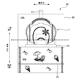
- FIG. 1 is a plan view of an absorbent article package 50 (hereinafter also referred to as “package”).
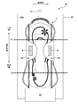
- FIG. 2 is a diagram showing the packaging body 50 in which the first folding section F1 is developed.
- FIG. 3 is a diagram showing the packaging body 50 in which the second folding portion F2 is expanded from FIG.
- FIG. 4 is a diagram showing the package body 50 which is completely unfolded.
- the packaging body 50 includes a sanitary napkin 1 (hereinafter also referred to as “napkin”) and a packaging material 20 that wraps the napkin 1 on the inner surface 20A.
- sanitary napkin 1 hereinafter also referred to as “napkin”
- packaging material 20 that wraps the napkin 1 on the inner surface 20A.
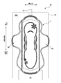
- FIG. 5 is a plan view of the napkin 1 viewed from the non-skin side.
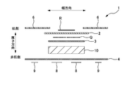
- FIG. 6 is a schematic sectional view of the napkin 1.
- the napkin 1 has a longitudinal direction, a width direction, and a thickness direction that are orthogonal to each other.
- the longitudinal direction of the napkin 1 the side in contact with the lower abdomen of the wearer is called “front side”, and the side in contact with the buttocks of the wearer is called “rear side”.
- the thickness direction of the napkin 1 the side in contact with the wearer's skin is called “skin side”, and the opposite side is called “non-skin side”.
- a liquid-permeable top sheet 2 As shown in FIG. 6, in the napkin 1, in order from the skin side in the thickness direction, a liquid-permeable top sheet 2, a liquid-permeable intermediate sheet 3, an absorbent body 10 that absorbs excrement, and a liquid impermeable body.
- the back sheet 4 having the property is laminated.
- the napkin 1 has a pair of wing portions 1W extending from the center portion in the longitudinal direction to both outer sides in the width direction.
- the wing portion 1W is formed by the back sheet 4 and the side sheet 6.
- the side sheets 6 extend from both ends in the width direction of the skin side surface of the top sheet 2 to both outer sides in the width direction.
- a central adhesive portion 8 is formed on the non-skin side surface of the napkin 1 (non-skin side surface of the backsheet 4).
- the central adhesive portion 8 is a hot melt adhesive application area for preventing the napkin 1 from slipping.
- the central adhesive portion 8 is attached to the skin side of clothing such as underwear, so that the napkin 1 is fixed to the clothing.
- a plurality of rectangular central adhesive portions 8 having long sides in the width direction of the napkin 1 are arranged at intervals in the width direction and the longitudinal direction.
- the shape, number, and arrangement of the central adhesive portions 8 are not limited to this.
- a wing adhesive portion 9 is formed on the non-skin side surface of each wing portion 1W (non-skin side surface of the backsheet 4).
- the wing adhesive portion 9 is a hot melt adhesive application area for preventing the wing portion 1W from slipping.
- the wing portion 1W is bent to the non-skin side, and the wing adhesive portion 9 is attached to the non-skin side surface of clothing such as underwear. As a result, the wing portion 1W is fixed to the clothes.
- one rectangular wing adhesive portion 9 having a long side in the longitudinal direction of the napkin 1 is arranged in each wing portion 1W.
- the shape, number, and arrangement of the wing adhesive portions 9 are not limited to this.
- the napkin 1 includes a cooling sensation material Q between the skin side sheet 2 and the intermediate sheet 3, which contains a compound that gives the wearer a cooling sensation or a refreshing sensation.
- the cooling sensation material Q is a volatile substance, and can be exemplified by a liquid containing menthol and menthyl lactate.
- the cooling sensation material Q is applied to the front surface or the back surface of the skin-side sheet 2, the front surface or the back surface of the intermediate sheet 3, the absorber 10 or the like at a desired place in a predetermined coating pattern according to the effect of the cooling sensation material Q. can do.
- the cooling sensation material Q may be applied to the non-skin side surface of the skin side sheet 2 during manufacturing.
- the cooling sensation material Q may be applied continuously from the front end to the rear end in the longitudinal direction.
- an oil film layer R is provided on the skin side surface of the skin side sheet 2 in a region which is considered to contact the vaginal opening of the wearer when worn.
- an oil film such as triacylglycerol can be used.
- the above napkin 1 is an example, and the present invention is not limited to this.
- the napkin 1 may not have the wing portion 1W, the intermediate sheet 3, or the like.
- the napkin 1 may have not the cooling sensation material Q but another volatile substance such as a warming sensation material or a fragrance.
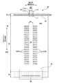
- FIG. 7 is a view showing the inner surface 20A of the packaging material 20.
- FIG. 8 is a cross-sectional view of the packaging material 20.
- the packaging material 20 is a rectangular sheet member. In the packaging material 20, the surface in contact with the napkin 1 is the inner surface 20A, and the opposite surface is the outer surface 20B.
- the packaging material 20 is located between the first layer 201 located on the inner surface side, the second layer 202 located on the outer surface side, and between the first layer 201 and the second layer 202. It has an intermediate layer 203, and each layer is adhered.
- the first layer 201 and the second layer 202 are layers containing a welding substance that enables the packaging materials 20 to be welded to each other.
- a modified polyethylene sheet (modified PE) containing 10% or more of maleic acid as an adhesive resin (adhesive substance) can be exemplified. It is preferable that at least the surface of the first layer 201 and the second layer 202 that is in contact with the intermediate layer 203 contains an adhesive resin.
- a sheet containing a resin capable of welding such as polypropylene (PP) instead of polyethylene (PE) may be used.
- the intermediate layer 203 is a layer containing a substance that can prevent volatilization of volatile substances.
- An example of the intermediate layer 203 is an ethylene-vinyl alcohol copolymer sheet (EVOH). Since the napkin 1 of the present embodiment includes the cooling sensation material Q, the intermediate layer 203 can prevent the cooling sensation material Q from volatilizing.
- the bonding between the first layer 201 and the intermediate layer 203 and the bonding between the intermediate layer 203 and the second layer 202 are performed while heating the intermediate layer 203 between the first layer 201 and the second layer 202 at about 76 degrees.
- the adhesive resin is melted and adhered.
- the thickness of the packaging material 20 can be made thinner than that when an adhesive is used.
- the first layer 201 and the second layer 202 do not have an adhesive resin, and the adhesive layer is provided between the first layer 201 and the intermediate layer 203 and between the intermediate layer 203 and the second layer 202.
- the provided 5-layer film may be used as the packaging material 20.
- the packaging material 20 is folded such that one end of the packaging material 20 on one side in the longitudinal direction is located outside the end on the other side. That is, one end of the packaging material 20 on the one side in the longitudinal direction becomes the unsealing portion 501 (see FIG. 1) of the packaging body 50. Therefore, a fastening tape 51 that fastens the unsealing portion 501 is provided at one end of the packaging material 20 on one side in the longitudinal direction.
- the fastening tape 51 is fixed to the outer surface of the packaging material 20 so that a part of the fastening tape 51 extends outward in the longitudinal direction of the packaging material 20.
- the fastening tape 51 has an adhesive portion 511 that is adhered to the packaging material 20 and a picking portion 512 that is not adhered to the packaging material 20.
- the packaging body 50 without the fastening tape 51 may be used.
- the inner surface 20A of the packaging material 20 does not have the peeling layer 204 at the end on one side in the longitudinal direction of the packaging material 20 (on the side of the fastening tape 51).
- a peeling section 21 is provided.
- a second non-peeling portion 23 having no peeling layer 204 is provided at the other end of the packaging material 20 in the longitudinal direction.
- a peeling portion 22 having a peeling layer 204 is provided on the other side of the non-peeling portion 21 in the longitudinal direction and on the one side of the second non-peeling portion 23 in the longitudinal direction.
- the peeling layer 204 is a layer capable of peeling the hot melt adhesive forming the central adhesive portion 8 of the napkin 1.
- An example of the peeling layer 204 is a layer in which a liquid containing a silicone resin is applied to the inner surface 20A of the packaging material 20.
- the napkin 1 is arranged on the inner surface 20A of the packaging material 20 with the skin side thereof facing upward.
- the longitudinal direction of the packaging material 20 is along the longitudinal direction of the napkin 1
- the width direction of the packaging material 20 is along the width direction of the napkin 1.
- the packaging material 20 is folded together with the napkin 1 with the skin side surface of the napkin 1 inward at two folding portions F1 and F2 along the width direction.
- the folded portion on one side (the fastening tape 51 side) in the longitudinal direction is referred to as a first folded portion F1
- the folded portion on the other side in the longitudinal direction with respect to the first folded portion F1 is referred to as a second folded portion F2.
- the number of folding parts is not limited to two, and may be one or three or more.
- the packaging material 20 may be folded not only at the folding portion along the width direction but also at the folding portion along the longitudinal direction.
- the state shown in FIG. 2 is obtained. Further, when the folding at the second folding portion F2 is developed, the state shown in FIG. 3 is obtained.
- the wing portion 1W of the napkin 1 is wrapped in a state of being folded back inward in the width direction.
- the napkin 1 has a release sheet 55, and the wing adhesive portion 9 is packaged in a state of being covered with the release sheet 55.
- the packaging body 50 has a welded portion 52 in which the packaging materials 20 are welded to each other at a side portion in a direction along the width direction (opening portion 501).
- a welding method in the welding portion 52 a well-known method such as heat sealing or ultrasonic sealing can be exemplified.
- the packaging body 50 also has an unsealing portion adhesive portion 54 that adheres the packaging materials 20 to each other in the unsealing portion 501. As shown in FIG. 7, the unsealing portion adhesive portion 54 is hot along the width direction of the packaging material 20 at the end on one side in the longitudinal direction of the inner surface 20A of the packaging material 20 (on the fastening tape 51 side). This is the area where the melt adhesive HMA is applied.
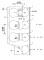
- 9A to 9C are explanatory views of the method for manufacturing the packaging material 20.
- 10 to 12 are explanatory views of the method for manufacturing the package 50.
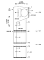
- 13A and 13B are explanatory diagrams of the width of the non-peeling portion 21.
- the packaging body 50 is manufactured by sequentially arranging a plurality of napkins 1 on the packaging material continuous body 20 ′ while the packaging material continuous body 20 ′ is transported with the continuous direction as the transport direction.
- the continuous body 20' of the packaging material is manufactured, for example, according to the flow shown in FIG. 9A.
- a multi-layer film f in which a first layer 201, an intermediate layer 203, and a second layer 202 are laminated is created (S01).
- the packaging material 20 has the design 25 as shown in FIG. 1, the design 25 is printed by gravure printing or the like on one surface of the film f (the outer surface 20B of the packaging material 20) (S02).
- the silicon layer 204 is partially applied to the other surface of the film f (the inner surface 20A of the packaging material 20) (S03). As shown in FIG.
- a plurality (here, three) of belt-shaped silicon layers 204 continuous in the continuous direction of the film f are applied at intervals in the width direction of the film f.
- the silicon layer 204 is applied to the inside in the width direction of the film f on both sides in the width direction.
- the film f is cut along the continuous direction at positions between the silicon layers 204 in the width direction of the film f, that is, positions between portions where the silicon layer 204 is not applied (S04).
- a film f in which the silicon layer 204 is not applied to both outer end portions of the silicon layer 204 is manufactured.
- the silicon layer 204 of the film f serves as the peeling portion 22 of the packaging material 20, and the outer ends of the silicon layer 204 serve as the non-peeling portion 21 and the second non-peeling portion 23.
- the continuous body 20' of the packaging material is manufactured.
- the continuous body 20 ′ of the packaging material wound into a roll is installed in the manufacturing apparatus for the packaging body 50, and the packaging body 50 is manufactured.
- the method for manufacturing the packaging body 50 includes a carrying step (S11) for carrying the continuous body 20′ of the packaging material, and hot melt bonding for the central adhesive portion 8 and the opening adhesive portion 54.
- First application step (S12) of applying the agent HMA, placement step (S13) of placing the napkin 1 on the continuous body 20′ of the packaging material, and second step of applying the hot melt adhesive HMA for the release sheet 55 The applying step (S14), the attaching step (S15) of attaching the fastening tape 51 to the continuous body 20' of the packaging material 20, the folding step (S16) of the continuous body 20' of the packaging material and the napkin 1, and the welding portion 52. Forming step (S17) and cutting step (S18).
- the continuous body 20' of the packaging material is carried with the continuous direction as the carrying direction.
- the transport direction corresponds to the width direction of the packaging material 20 and the napkin 1
- the CD direction (orthogonal direction) orthogonal to the transport direction corresponds to the longitudinal direction of the packaging material 20 and the napkin 1. Therefore, as shown in FIG. 10, on the inner surface 20A of the continuous body 20′ of the packaging material, a non-peeling portion 21 continuous in the transport direction is provided at one end on the CD direction side. Also, the continuous body 20′ of the packaging material is transported in a state where the peeling portion 22 continuous in the transport direction is provided on the other side in the CD direction.
- the hot melt adhesive HMA for the central adhesive portion 8 and the opening adhesive portion 54 is directly applied to the inner surface 20A of the continuous body 20' of the packaging material.
- the hot melt adhesive HMA for the central adhesive portion 8 (for preventing the absorbent article from shifting) is applied to the peeling portion 22 of the packaging material 20.
- the hot melt adhesive HMA for the unsealing part adhesive part 54 (to bond the unsealing part) is applied to the non-peeling part 21 of the packaging material 20.
- the napkin 1 manufactured in a separate line is arranged on the hot melt adhesive HMA for the central adhesive portion 8 with its non-skin side facing the hot melt adhesive HMA. Since the hot melt adhesive HMA for the central adhesive portion 8 is applied to the peeling portion 22, when the user peels off the napkin 1 from the packaging material 20 and uses the hot melt adhesive HMA on the non-skin side surface of the napkin 1. Is transcribed.
- the plurality of napkins 1 are sequentially arranged on the continuous body 20' of the packaging material. Therefore, as shown in FIG. 10, the hot melt adhesive HMA for each central adhesive portion 8 of the plurality of napkins 1 is applied at intervals in the transport direction.
- the hot melt adhesive HMA at high temperature is directly applied to the continuous body 20' of the packaging material, if the continuous body 20' of the packaging material has a low softening point (high thermal conductivity), it is packaged by heat.
- the continuous body 20' of the material contracts and wrinkles occur.
- wrinkles occur in the continuous body 20′ of the packaging material. Areas with wrinkles and areas without wrinkles are alternately arranged in the transport direction.
- the tension applied to convey the continuous body 20 ′ of the packaging material may not be stable and may be loosened, so that the appearance of the packaging body 50 may not be finished neatly. For example, there is a risk that the package 50 may be wrinkled or that the napkin 1 is not placed at an appropriate position on the packaging material 20.
- the hot-melt adhesive is also applied to the central adhesive portion 8 of each napkin 1 at intervals in the transport direction and the CD direction. Therefore, the wrinkled region and the wrinkle-free region are dispersed in the transport direction and the CD direction, and it is difficult to stabilize tension in transporting the continuous body 20' of the packaging material.
- the hot melt adhesive HMA for the central adhesive portion 8 is applied to the peeling portion 22. Since the peeling portion 22 has a larger number of layers and a larger thickness than the non-peeling portion 23 by the peeling layer 204, it is less likely that the continuous body 20' of the packaging material is wrinkled by heat. Further, the silicon contained in the peeling layer 204 has a higher softening point than the welding substances such as PE and PP contained in the first layer 201 and the second layer 202. From this point as well, it can be said that wrinkles due to heat do not easily occur in the peeling portion 22. Therefore, even when the hot-melt adhesive HMA is applied intermittently in the transport direction, wrinkles hardly occur in the peeling portion 22 in the transport direction intermittently, and the tension for transporting the continuous body 20′ of the packaging material is stabilized. Can be made
- the hot melt adhesive HMA for the unsealing part adhesive part 54 is applied to the non-peeling part 21 where wrinkles are more likely to occur than the peeling part 22. Therefore, the hot-melt adhesive HMA for each opening part adhesive part 54 of the plurality of napkins 1 is continuously applied to the non-peeling part 21 in the transport direction.
- the packaging material 20 of the present embodiment also has an intermediate layer 203 that is a protective layer that prevents volatilization of volatile substances of the napkin 1.
- the gas barrier substance such as EVOH contained in the intermediate layer 203 has a higher softening point than the welding substances such as PE and PP contained in the first layer 201 and the second layer 202. Therefore, the thermal conductivity of the intermediate layer 203 is lower than that of the first layer 201 and the second layer 202. That is, in the continuous body 20' of the packaging material, layers having different thermal conductivities are laminated.
- the intermediate layer 203 having a high softening point wrinkles due to the hot melt adhesive HMA are less likely to occur. Since the intermediate layer 203 is arranged on the entire packaging material 20, wrinkles are less likely to occur on the entire packaging material 20. Therefore, it is possible to suppress the occurrence of wrinkles in the appearance of the package 50, and to finish the package 50 more neatly.
- the packaging material is arranged so that one end (non-peeling portion 21 side) end of the packaging material continuous body 20′ in the CD direction is located outside the other end.
- the continuum 20′ and the napkin 1 are folded in the CD direction. Therefore, the unsealing portion 501 of the packaging body 50 is bonded to the packaging material 20 by the unsealing portion adhesive portion 54. Therefore, the airtightness of the package 50 is improved, and it is possible to prevent the volatile substance from being released to the outside before using the napkin 1.
- the adhesive strength of the unsealing portion 501 is higher and the sealing property of the package 50 is higher when the unsealing portion 21 is applied. Will be higher.
- it becomes difficult to open the package 50 it is possible to prevent the package 50 from being unnecessarily opened before use, and it is possible to suppress volatilization of the volatile substance of the napkin 1.
- the central adhesive portion 8 is formed in a portion inside the peeling portion 22 of the packaging material 20 inside both ends in the width direction of the packaging material 20. Therefore, the central adhesive portion 8 can be covered with the napkin 1. Further, in the non-peeling portion 21 of the packaging material 20, the unsealing portion adhesive portion 54 is formed from one end to the other end in the width direction. Therefore, the unsealing portion 501 of the package 50 is adhered over the entire width direction, and the hermeticity of the package 50 is further enhanced.
- a known method can be used to confirm that the layers having different thermal conductivities are stacked in the packaging material 20.
- a part of the packaging material 20 is cut out as a sample, the sample is embedded using an epoxy resin, and then the sample is cut in the thickness direction with an ultramicrotome. Then, the cut surface of the sample is photographed with an optical microscope to measure the thickness of each layer of the packaging material 20.
- each layer is separated from the sample, the infrared absorption spectrum of each layer is measured by the microscopic transmission method, and the main substances constituting each layer are analyzed. The thermal conductivity of each layer is calculated and compared based on the thickness of each layer and the thermal conductivity of the constituent materials.
- the method of confirming the peeling portion 22 and the non-peeling portion 21 (second non-peeling portion 23) on the inner surface 20A of the packaging material 20 can be performed by a known method.
- the peeling portion 22 has lower wettability (harder to wet) than the non-peeling portion 21 (23). Therefore, according to JIS K 6768:1999, the target site on the inner surface 20A of the packaging material 20 (for example, one end in the longitudinal direction (non-peeling part 21) and the part inside the longitudinal direction (peeling part). )), the wettability test mixed solution is dropped, and the wettability of each part is evaluated.
- a method of confirming with a dyne pen for wettability evaluation can be exemplified.
- the non-peeling portion 21 is provided at one end in the CD direction on the inner side surface 20A of the continuous body 20′ of the packaging material, and the other end in the CD direction is provided at the end.
- a second non-peeling portion 23 that is continuous in the transport direction is provided.
- Neither the non-peeling portion 21 nor the second non-peeling portion 23 has the peeling layer 204, and the rigidity is about the same. Therefore, tension can be applied in the same degree at the two widthwise end portions of the packaging material continuous body 20', and the packaging material continuous body 20' can be more stably transported. Therefore, the appearance of the package 50 can be finished neatly.
- the wing portion 1W is folded back inside the width direction, and the release sheet 55 is arranged on the wing portion 1W. Further, the hot melt adhesive HMA for the wing adhesive portion 9 is applied to the release sheet 55, and when the release sheet 55 is released, the hot melt adhesive HMA for the wing adhesive portion 9 is transferred to the wing portion 1W. I shall. As shown in FIG. 11, after the napkin 1 arranging step (S13), a hot melt adhesive 56 (HMA) for adhering the release sheet 55 and the second non-release section 23 is applied on the release sheet 55. (S14).
- HMA hot melt adhesive 56
- the surface of the release sheet 55 facing the wing portion 1W is a surface on which the adhesive is more easily peeled off than the side surface opposite thereto. Then, in the folding step (S16), the release sheet 55 and the second non-peelable portion 23 are bonded with the hot melt adhesive 56 on the release sheet 55.
- the release sheet 55 on which the adhesive does not easily peel off and the second non-peeling portion 23 are adhered, so that the adhesive strength between the release sheet 55 and the packaging material 20 is strengthened. Therefore, when the packaging body 50 is developed, the release sheet 55 is peeled from the wing adhesive portion 9 and is in a state of being adhered to the packaging material 20. Therefore, it is possible to save the user the trouble of peeling the release sheet 55.
- the present invention is not limited to the above, and the hot-melt adhesive 56 (hereinafter, "hot-melt adhesive for release sheet") for adhering the release sheet 55 and the second non-release section 23 is directly applied to the second non-release section 23.
- the width of the release sheet 55 is preferably smaller than the width of the packaging material 20 so that the release sheet 55 does not protrude in the package 50. Therefore, it is necessary to intermittently apply the release sheet hot-melt adhesive agent 56 to the second non-peeling portion 23 in which wrinkles are likely to occur due to heat, in the transport direction. Therefore, as described above, it is preferable to apply the release sheet hot-melt adhesive 56 on the release sheet 55. By doing so, it is possible to prevent the tension applied to the second non-peeling portion 23 from becoming unstable in the carrying step.
- the hot melt adhesive 56 for the release sheet is applied in the time period from the application of the hot melt adhesive 56 for the release sheet on the release sheet 55 until the release sheet 55 and the second non-peelable portion 23 are bonded.
- the temperature of can be lowered. Therefore, the generation of wrinkles in the second non-peeling portion 23 can be suppressed, and the appearance of the package 50 can be finished neatly.
- the layer having a high thermal conductivity may be arranged on the outer surface side of the layer having a low thermal conductivity (intermediate layer 203).
- intermediate layer 203 the layer having a low thermal conductivity
- the second layer 202 having a high thermal conductivity and the non-peeling portion 21 are formed by the hot melt adhesive HMA for the opening adhesive portion 54. And are glued together.
- the temperature of the hot-melt adhesive HMA decreases during the time from the application of the hot-melt adhesive HMA to the non-peeling portion 21 until the bonding of the second layer 202 and the non-peeling portion 21. Therefore, it is possible to suppress the occurrence of wrinkles in the second layer 202 due to the hot melt adhesive HMA for the unsealed portion adhesive portion 54.
- a pair of welded portions 52 is formed between the napkins 1 arranged in the transport direction (S17). Therefore, since the layer having high thermal conductivity (second layer 202) is arranged on the outer side surface side of the layer having low thermal conductivity (intermediate layer 203), the packaging materials 20 are easily welded to each other, and the welding portion is The strength of 52 can be increased. Conversely speaking, the temperature at the time of welding can be lowered, and the occurrence of wrinkles in the packaging material 20 due to the formation of the welding portion 52 can be suppressed. Therefore, the appearance of the package 50 can be finished neatly.
- the hot melt adhesive is applied to both sides of the non-application area 24 of the hot melt adhesive in the transport direction as the central adhesive portion 8 of the napkin 1 (that is, the first adhesive step).
- the first coating area 8A and the second coating area 8B are formed at intervals in the carrying direction).
- the fastening tape 51 is formed in the width direction (conveying direction) of the packaging material 20, at the position of the packaging material 20 (continuous body 20′) that overlaps at least a part of the non-application area 24, the fastening tape 51 is formed. Is preferably attached.
- the fastening tape 51 can be attached neatly.
- the part of the fastening tape 51 projecting from the unsealing part 501 of the package 50 can be neatly attached to the non-application area 24.
- the length W1 of the non-application area 24 in the transport direction (width direction) is made longer than the width W2 of the fastening tape 51 (W1>W2).
- the fastening tape 51 may be attached so that the length L1 is longer than the length L2 of the non-peeling portion 21 (L1>L2).
- the peeling portion 22 has as many layers as the peeling layer 204 and has high strength. Therefore, when the fastening tape 51 is peeled to open the packaging body 50, the peeling portion 22 is unlikely to tear, and the packaging body 50 can be opened without the root of the fastening tape 51 coming off the peeling portion 22.
- the fastening tape 51 may be attached so that L3 is longer than the length L2 of the non-peeling portion 21 (L3>L2).
- the fastening tape 51 can be peeled off from the inner surface of the packaging material 20, and the fastening tape 51 can be used when the napkin is discarded.
- the length L2 of the non-peeling portion 21 is relatively short in the longitudinal direction (CD direction) of the packaging material 20, and is shorter than the length of the second non-peeling portion 23.
- the length of the non-peeling portion 21 is not limited to this, and may be equal to or longer than the length of the second non-peeling portion 23 in the longitudinal direction of the packaging material 20.
- the length of the non-peelable portion 21 is longer than the length L1 of the adhesive portion 511 of the fastening tape 51 fixed to the unsealing portion 501 and the length L3 of the adhesive portion 511 of the fastening tape 51 protruding from the unsealing portion 501. L2 may be lengthened.
- the length L1 of the adhesive portion 511 of the fastening tape 51 fixed to the unsealing portion 501 in the longitudinal direction (CD direction) of the packaging material 20 may be shorter than the total length of the entire length L4 of the adhesive portion 511 (L1+L4>L2).
- the fastening tape 51 can be peeled off from the inner surface of the packaging material 20, and the fastening tape 51 can be used when the napkin is discarded.
- the manufacturing method of the package 50 shown in FIGS. 10 to 12 is an example, and the manufacturing method is not limited to this.
- the adhesive forming the wing adhesive section 9 may not be a hot melt adhesive, or the adhesive for the wing adhesive section 9 may be applied to the release sheet 55 side and transferred to the wing section 1W.
- the fastening tape 51 may be fixed after the continuous body 20′ of the packaging material is folded, or may be folded or welded after the continuous body 20′ of the packaging material is cut into the product size. May be formed.
- the absorbent article may not have a volatile substance.
Landscapes
- Health & Medical Sciences (AREA)
- Epidemiology (AREA)
- Engineering & Computer Science (AREA)
- Biomedical Technology (AREA)
- Heart & Thoracic Surgery (AREA)
- Vascular Medicine (AREA)
- Life Sciences & Earth Sciences (AREA)
- Animal Behavior & Ethology (AREA)
- General Health & Medical Sciences (AREA)
- Public Health (AREA)
- Veterinary Medicine (AREA)
- Absorbent Articles And Supports Therefor (AREA)
Abstract
吸収性物品包装体(50)の製造方法であって、熱伝導率の異なる層が積層された包装材(20)の連続体であって、内側面において、連続方向の直交方向の一方側の端部に剥離層を有さない非剥離部(21)が設けられ、非剥離部(21)よりも直交方向の他方側に剥離層を有する剥離部(22)が設けられている包装材(20)の連続体を、連続方向を搬送方向として搬送する工程と、剥離部(22)に、複数の吸収性物品(1)の各ずれ止め用のホットメルト接着剤(8)を搬送方向に間隔をあけて塗布し、非剥離部(21)に複数の吸収性物品包装体(1)の各開封部を接着するホットメルト接着剤(9)を搬送方向に連続して塗布する工程と、を有すること。
Description
本発明は、吸収性物品包装体の製造方法、及び、吸収性物品包装体に関する。
生理用ナプキン等の吸収性物品の非肌対向面には、吸収性物品を着衣に固定する粘着部が設けられている。特許文献1には、吸収性物品と、これを個別包装する包装材とを含む吸収性物品包装体(個別包装体)が開示されている。この包装体の包装材は、内面に剥離処理部を有する。そのため、吸収性物品の粘着部は、剥離処理されたシートを介さずに、包装材の剥離処理部に粘着している。
特許文献1の包装体のように、吸収性物品が包装材に直接粘着している場合、包装材の内面の剥離処理部にホットメルト接着剤を塗布し、ホットメルト接着剤上に吸収性物品を配置することで、包装材のホットメルト接着剤を吸収性物品の非肌側面に転写させて、吸収性物品の粘着部とすることができる。
また、吸収性物品包装体の製造方法として、搬送方向に連続して搬送される包装材の連続体上に、複数の吸収性物品を搬送方向に間欠に配置した後、製品サイズに合わせて包装材の連続体を切断する方法が知られている。
これらの製造方法の場合、搬送方向に連続して搬送される包装材の連続体上に、吸収性物品の粘着部を形成するためのホットメルト接着剤が、搬送方向に間欠に塗布される。また、ホットメルト接着剤のように熱い物質が包装材に塗布されると、包装材が収縮して皺が発生しやすい。そのため、上記の製造方法の場合、ホットメルト接着剤による皺が搬送方向に間欠に発生する。その結果、包装材の連続体を搬送する張力の掛かり方が安定せずに弛む等して、吸収性物品包装体の外観を綺麗に仕上げることができない恐れがある。
本発明は、上記のような従来の問題に鑑みてなされたものであって、その目的は、包装材の内側面にホットメルト接着剤を塗布する場合において、吸収性物品包装体の外観を綺麗に仕上げることである。
上記目的を達成するための主たる発明は、吸収性物品と、前記吸収性物品を内側面に載せて包装する包装材と、を備えた吸収性物品包装体の製造方法であって、熱伝導率の異なる層が積層された前記包装材の連続体であって、前記内側面において、前記包装材の連続体の連続方向に直交する直交方向の一方側の端部に、剥離層を有さない非剥離部が設けられ、前記非剥離部よりも前記直交方向の他方側に、剥離層を有する剥離部が設けられている前記包装材の連続体を、前記連続方向を搬送方向として搬送する工程と、前記剥離部に、複数の前記吸収性物品の各ずれ止め用のホットメルト接着剤を、前記搬送方向に間隔をあけて塗布し、前記非剥離部に、複数の前記吸収性物品包装体の各開封部を接着するホットメルト接着剤を、前記搬送方向に連続して塗布する工程と、前記ずれ止め用のホットメルト接着剤上に、前記吸収性物品を配置した後に、前記直交方向における前記包装材の前記一方側の端部が前記他方側の端部よりも外側に位置するように、前記包装材、及び、前記吸収性物品を前記直交方向に折り畳む工程と、を有することを特徴とする吸収性物品包装体の製造方法である。
本発明の他の特徴については、本明細書及び添付図面の記載により明らかにする。
本発明の他の特徴については、本明細書及び添付図面の記載により明らかにする。
本発明によれば、包装材の内側面にホットメルト接着剤を塗布する場合において、吸収性物品包装体の外観を綺麗に仕上げることができる。
本明細書及び添付図面の記載により、少なくとも以下の事項が明らかとなる。
吸収性物品と、前記吸収性物品を内側面に載せて包装する包装材と、を備えた吸収性物品包装体の製造方法であって、熱伝導率の異なる層が積層された前記包装材の連続体であって、前記内側面において、前記包装材の連続体の連続方向に直交する直交方向の一方側の端部に、剥離層を有さない非剥離部が設けられ、前記非剥離部よりも前記直交方向の他方側に、剥離層を有する剥離部が設けられている前記包装材の連続体を、前記連続方向を搬送方向として搬送する工程と、前記剥離部に、複数の前記吸収性物品の各ずれ止め用のホットメルト接着剤を、前記搬送方向に間隔をあけて塗布し、前記非剥離部に、複数の前記吸収性物品包装体の各開封部を接着するホットメルト接着剤を、前記搬送方向に連続して塗布する工程と、前記ずれ止め用のホットメルト接着剤上に、前記吸収性物品を配置した後に、前記直交方向における前記包装材の前記一方側の端部が前記他方側の端部よりも外側に位置するように、前記包装材、及び、前記吸収性物品を前記直交方向に折り畳む工程と、を有することを特徴とする吸収性物品包装体の製造方法である。
吸収性物品と、前記吸収性物品を内側面に載せて包装する包装材と、を備えた吸収性物品包装体の製造方法であって、熱伝導率の異なる層が積層された前記包装材の連続体であって、前記内側面において、前記包装材の連続体の連続方向に直交する直交方向の一方側の端部に、剥離層を有さない非剥離部が設けられ、前記非剥離部よりも前記直交方向の他方側に、剥離層を有する剥離部が設けられている前記包装材の連続体を、前記連続方向を搬送方向として搬送する工程と、前記剥離部に、複数の前記吸収性物品の各ずれ止め用のホットメルト接着剤を、前記搬送方向に間隔をあけて塗布し、前記非剥離部に、複数の前記吸収性物品包装体の各開封部を接着するホットメルト接着剤を、前記搬送方向に連続して塗布する工程と、前記ずれ止め用のホットメルト接着剤上に、前記吸収性物品を配置した後に、前記直交方向における前記包装材の前記一方側の端部が前記他方側の端部よりも外側に位置するように、前記包装材、及び、前記吸収性物品を前記直交方向に折り畳む工程と、を有することを特徴とする吸収性物品包装体の製造方法である。
このような吸収性物品包装体の製造方法によれば、熱伝導率の低い層によって、ホットメルト接着剤の熱による皺が包装材に生じ難くなり、吸収性物品包装体の外観を綺麗に仕上げることができる。また、剥離部は、剥離層を有するため、ホットメルト接着剤の熱により皺が生じにくい。そのため、剥離部にホットメルト接着剤が搬送方向に間隔をあけて塗布されても、包装材の連続体を搬送する張力を安定させることができる。一方、非剥離部はホットメルト接着剤の熱により皺が生じやすいが、非剥離部にはホットメルト接着剤が搬送方向に連続して塗布されるため、皺が搬送方向に連続して均一に生じ、包装材の連続体を搬送する張力を安定させることができる。よって、吸収性物品包装体の外観を綺麗に仕上げることができる。
かかる吸収性物品包装体の製造方法であって、前記吸収性物品は揮発性物質を有し、前記熱伝導率の低い層は、前記揮発性物質の揮発を防ぐ保護層であることを特徴とする吸収性物品包装体の製造方法である。
このような吸収性物品包装体の製造方法によれば、熱伝導率の低い保護層によって、ホットメルト接着剤の熱による皺が包装材に生じ難くなり、吸収性物品包装体の外観を綺麗に仕上げることができる。
かかる吸収性物品包装体の製造方法であって、前記吸収性物品は、ウィング部と、前記ウィング部のずれ止め用の接着剤を覆う剥離シートとを有し、前記搬送する工程では、前記包装材の連続体の前記内側面における、前記直交方向の前記他方側の端部に、剥離層を有さない第2の非剥離部が設けられている状態で、前記包装材の連続体を搬送し、前記折り畳む工程では、前記包装材及び前記吸収性物品を折り畳みつつ、ホットメルト接着剤で、前記剥離シートと前記第2の非剥離部とを接着することを特徴とする吸収性物品包装体の製造方法である。
このような吸収性物品包装体の製造方法によれば、包装材の連続体の幅方向の両端部において搬送時の張力の掛かり方を同程度にでき、包装材の連続体を安定して搬送できる。
かかる吸収性物品包装体の製造方法であって、前記吸収性物品の幅方向の内側に折り返された前記ウィング部上に配置されている前記剥離シートと、前記第2の非剥離部とを接着する前記ホットメルト接着剤を、前記剥離シート上に塗布する工程を有することを特徴とする吸収性物品包装体の製造方法である。
このような吸収性物品包装体の製造方法によれば、剥離シート上にホットメルト接着剤が塗布されてから、剥離シートと第2の非剥離部とが接着されるまでの時間において、ホットメルト接着剤の温度が下がる。よって、第2の非剥離部での皺の発生を抑制できる。
かかる吸収性物品包装体の製造方法であって、前記包装材において、前記熱伝導率の高い層が前記熱伝導率の低い層よりも外側面側に配置されており、前記折り畳む工程では、前記包装材及び前記吸収性物品を折り畳みつつ、前記開封部を接着するホットメルト接着剤で、前記熱伝導率の高い層と前記非剥離部とを接着することを特徴とする吸収性物品包装体の製造方法である。
このような吸収性物品包装体の製造方法によれば、包装材の内側面に塗布されたホットメルト接着剤の熱が、外側面側の、熱伝導率の高い層に伝わり難く、皺が生じ難くなる。
かかる吸収性物品包装体の製造方法であって、前記吸収性物品包装体は、前記開封部に沿う方向の側部において、前記包装材同士が溶着された溶着部を有し、前記折り畳む工程の後に、前記溶着部を形成する工程を有することを特徴とする吸収性物品包装体の製造方法である。
このような吸収性物品包装体の製造方法によれば、包装材の外側面側の、熱伝導率の高い層により、包装材同士が溶着されやすくなる。
かかる吸収性物品包装体の製造方法であって、前記塗布する工程では、1個あたりの前記吸収性物品の前記ずれ止め用のホットメルト接着剤として、当該ホットメルト接着剤の非塗布領域の前記搬送方向の両側に、当該ホットメルト接着剤を塗布し、前記搬送方向において、前記非塗布領域の少なくとも一部と重複する前記包装材の位置に、前記開封部を止着する止着テープを取り付ける工程を有することを特徴とする吸収性物品包装体の製造方法である。
このような吸収性物品包装体の製造方法によれば、皺が生じ難く、搬送方向に張っている包装材の位置に、止着テープを綺麗に取り付けることができる。
かかる吸収性物品包装体の製造方法であって、前記開封部を止着する止着テープを前記包装材に取り付ける工程を有し、前記取り付ける工程では、前記直交方向において、前記開封部に固定する前記止着テープの粘着部の長さを、前記非剥離部の長さよりも長くすることを特徴とする吸収性物品包装体の製造方法である。
このような吸収性物品包装体の製造方法によれば、止着テープの根元(開封部側)の一部が、破れ難い剥離部に粘着されるため、止着テープの根元が剥離部から外れることなく吸収性物品包装体を開封できる。
かかる吸収性物品包装体の製造方法であって、前記開封部を止着する止着テープを前記包装材に取り付ける工程を有し、前記取り付ける工程では、前記直交方向において、前記開封部から突出する前記止着テープの粘着部の長さを、前記非剥離部の長さよりも長くすることを特徴とする吸収性物品包装体の製造方法である。
このような吸収性物品包装体の製造方法によれば、包装体の開封後に止着テープが折れ曲がったとしても、止着テープの粘着部の一部は剥離部に接着しやすいため、止着テープを包装材の内側面から剥がすことができる。
また、吸収性物品と、前記吸収性物品を内側面に載せて包装する包装材と、を備えた吸収性物品包装体であって、前記包装材では、熱伝導率の異なる層が積層されており、前記包装材の前記内側面において、前記包装材の長手方向の一方側の端部に、剥離層を有さない非剥離部が設けられ、前記非剥離部よりも前記長手方向の他方側に、剥離層を有する剥離部が設けられており、前記剥離部のうち、前記包装材の幅方向の両端よりも内側の部位に、前記吸収性物品のずれ止め用のホットメルト接着剤の塗布領域が形成されており、前記非剥離部において、前記吸収性物品包装体の開封部を接着するホットメルト接着剤の塗布領域が、前記幅方向の一端から他端まで形成されており、前記長手方向における前記包装材の前記一方側の端部が前記他方側の端部よりも外側に位置するように、前記包装材、及び、前記吸収性物品が折り畳まれていることを特徴とする吸収性物品包装体である。
このような吸収性物品包装体によれば、熱伝導率の低い層によって、ホットメルト接着剤の熱による皺が包装材に生じ難くなり、吸収性物品包装体の外観を綺麗に仕上げることができる。また、吸収性物品包装体の製造時に、包装材の連続体を搬送する張力が安定するため、吸収性物品包装体の外観を綺麗に仕上げることができる。
かかる吸収性物品包装体であって、前記吸収性物品は揮発性物質を有し、前記熱伝導率の低い層は、前記揮発性物質の揮発を防ぐ保護層であることを特徴とする吸収性物品包装体である。
このような吸収性物品包装体によれば、熱伝導率の低い保護層によって、ホットメルト接着剤の熱による皺が包装材に生じ難く、吸収性物品包装体の外観を綺麗に仕上げることができる。
かかる吸収性物品包装体であって、前記吸収性物品は、ウィング部と、前記ウィング部のずれ止め用の接着剤を覆う剥離シートとを有し、前記包装材の前記内側面において、前記長手方向の前記他方側の端部に、剥離層を有さない第2の非剥離部が設けられており、ホットメルト接着剤で前記剥離シートと前記第2の非剥離部とが接着されていることを特徴とする吸収性物品包装体である。
このような吸収性物品包装体によれば、剥離シートと包装材(第2の非剥離部)の接着強度が強く、開封時に剥離シートが包装材に接着されたままとなり、ユーザーが剥離シートを剥がす手間を省ける。
かかる吸収性物品包装体であって、前記包装材において、前記熱伝導率の高い層が前記熱伝導率の低い層よりも外側面側に配置されており、前記開封部を接着するホットメルト接着剤で、前記熱伝導率の高い層と前記非剥離部とが接着されていることを特徴とする吸収性物品包装体である。
このような吸収性物品包装体によれば、包装材の内側面に塗布されたホットメルト接着剤の熱が、外側面側の、熱伝導率の高い層に伝わり難く、皺が生じ難くなる。
かかる吸収性物品包装体であって、前記吸収性物品の前記ずれ止め用のホットメルト接着剤の塗布領域は、第1塗布領域と、第2塗布領域とを、前記幅方向に間隔をあけて有し、前記幅方向において、前記第1塗布領域と前記第2塗布領域の間の非塗布領域の少なくとも一部と重複する前記包装材の位置に、前記開封部を止着する止着テープが取り付けられていることを特徴とする吸収性物品包装体である。
このような吸収性物品包装体によれば、止着テープが包装材に綺麗に取り付けられている。
===実施形態===
以下、本発明に係る吸収性物品包装体の吸収性物品として生理用ナプキンを例に挙げて実施形態を説明する。ただし、生理用ナプキンに限らず、パンティーライナー、又は軽失禁用パッド等のように、使用者の着衣に固定して使用する吸収性物品であればよい。
以下、本発明に係る吸収性物品包装体の吸収性物品として生理用ナプキンを例に挙げて実施形態を説明する。ただし、生理用ナプキンに限らず、パンティーライナー、又は軽失禁用パッド等のように、使用者の着衣に固定して使用する吸収性物品であればよい。
<<吸収性物品包装体50について>>
図1は、吸収性物品包装体50(以下「包装体」ともいう)の平面図である。図2は、第1折り部F1が展開された包装体50を示す図である。図3は、図2から第2折り部F2が展開された包装体50を示す図である。図4は、完全に展開された包装体50を示す図である。
図1は、吸収性物品包装体50(以下「包装体」ともいう)の平面図である。図2は、第1折り部F1が展開された包装体50を示す図である。図3は、図2から第2折り部F2が展開された包装体50を示す図である。図4は、完全に展開された包装体50を示す図である。
包装体50は、生理用ナプキン1(以下「ナプキン」ともいう)と、ナプキン1を内側面20Aに載せて包装する包装材20とを備えている。
(ナプキン1の基本構成)
図5は、ナプキン1を非肌側から見た平面図である。図6は、ナプキン1の概略断面図である。
図5は、ナプキン1を非肌側から見た平面図である。図6は、ナプキン1の概略断面図である。
ナプキン1は、互いに直交する長手方向、幅方向、及び厚さ方向を有する。ナプキン1の長手方向において、着用者の下腹部に当接する側を「前側」といい、着用者の臀部に当接する側を「後側」という。ナプキン1の厚さ方向において、着用者の肌に当接する側を「肌側」といい、その反対側を「非肌側」という。
図6に示すように、ナプキン1では、厚さ方向の肌側から順に、液透過性のトップシート2、液透過性の中間シート3、排泄物を吸収する吸収体10、及び、液不透過性のバックシート4が積層されている。
また、ナプキン1は、長手方向の中央部から幅方向の両外側に延出した一対のウィング部1Wを有する。ウィング部1Wは、バックシート4及びサイドシート6によって形成されている。サイドシート6は、トップシート2の肌側面の幅方向の端部から幅方向の両外側に延出している。
図5に示すように、ナプキン1の非肌側面(バックシート4の非肌側面)には、中央粘着部8が形成されている。中央粘着部8とは、ナプキン1のずれ止め用のホットメルト接着剤の塗布領域である。ナプキン1の使用時に中央粘着部8が下着等の着衣の肌側面に貼り付けられることで、ナプキン1は着衣に固定される。図5では、ナプキン1の幅方向に長辺を有する長方形状の中央粘着部8が、幅方向及び長手方向にそれぞれ間隔を空けて複数配置されている。ただし、中央粘着部8の形状、数、及び配置はこれに限られない。
同様に、各ウィング部1Wの非肌側面(バックシート4の非肌側面)には、ウィング粘着部9が形成されている。ウィング粘着部9とは、ウィング部1Wのずれ止め用のホットメルト接着剤の塗布領域である。ナプキン1の使用時にウィング部1Wは非肌側に折り曲げられ、ウィング粘着部9は下着等の着衣の非肌側面に張り付けられる。これにより、ウィング部1Wは着衣に固定される。図5では、ナプキン1の長手方向に長辺を有する長方形状のウィング粘着部9が各ウィング部1Wに1つずつ配置されている。ただし、ウィング粘着部9の形状、数、及び配置はこれに限られない。
また、図6に示すように、ナプキン1は、肌側シート2と中間シート3の間に、着用者に対して冷感や清涼感を与える化合物を含む冷感材料Qを備える。冷感材料Qは、揮発性の物質であり、メントールと乳酸メンチルを含有する液体を例示することができる。冷感材料Qは、肌側シート2の表面又は裏面、中間シート3の表面や裏面、吸収体10等に、冷感材料Qの効果に応じて、所望の場所に、所定の塗布パターンで塗布することができる。例えば、製造時において、肌側シート2の非肌側面に冷感材料Qを塗布するとよい。また、例えば、ナプキン1の幅方向の中央領域において、長手方向の前側端から後側端まで連続して、冷感材料Qを塗布するとよい。
また、着用時において、着用者の膣口に当接すると考えられる領域の、肌側シート2の肌側面には、油膜層Rが設けられていることが好ましい。油膜層Rとして、トリアシルグリセロール等の油膜を用いることができる。これにより、冷感材料Qが直接的に着用者の陰部に接触することを抑制でき、着用者に適度な冷感効果を付与できる。
なお、上記のナプキン1は一例であり、これに限定されない。例えば、ナプキン1は、ウィング部1Wや中間シート3等を有していなくてもよい。また、ナプキン1が冷感材料Qではなく、温感材料や香料等の別の揮発性物質を有していてもよい。
(包装材20の基本構成)
図7は、包装材20の内側面20Aを示す図である。図8は、包装材20の断面図である。包装材20は、長方形状のシート部材である。包装材20において、ナプキン1と接する面を内側面20Aとし、その反対の面を外側面20Bとする。
図7は、包装材20の内側面20Aを示す図である。図8は、包装材20の断面図である。包装材20は、長方形状のシート部材である。包装材20において、ナプキン1と接する面を内側面20Aとし、その反対の面を外側面20Bとする。
包装材20は、図8に示すように、内側面側に位置する第1層201と、外側面側に位置する第2層202と、第1層201と第2層202の間に位置する中間層203を有し、各層が接着されている。
第1層201及び第2層202は、包装材20同士の溶着を可能とする溶着物質を含有する層とする。第1層201及び第2層202として、接着性樹脂(接着物質)であるマレイン酸を10%以上含有する変性ポリエチレンシート(変性PE)を例示できる。第1層201及び第2層202について、少なくとも中間層203と接する側の面に、接着性樹脂を含有することが好ましい。その他、ポリエチレン(PE)に替えてポリプロピレン(PP)等の溶着が可能な樹脂を含有するシートでもよい。
中間層203は、揮発性物質の揮発を防ぐことができる物質を含有する層とする。中間層203として、エチレン‐ビニルアルコール共重合体シート(EVOH)を例示できる。本実施形態のナプキン1は冷感材料Qを備えるので、中間層203により冷感材料Qの揮発を防止できる。
第1層201と中間層203の接合、及び中間層203と第2層202の接合は、中間層203を第1層201と第2層202で挟んだ状態で、約76度に加熱しながら加圧することで、接着性樹脂が溶融されて接着する。第1層201及び第2層202に変性PEを用いることで、接着剤を用いる場合よりも包装材20の厚みを薄くすることができる。
ただし、上記に限定されない。例えば、第1層201及び第2層202が接着性樹脂を有さずに、第1層201と中間層203の間、及び、中間層203と第2層202の間に、接着剤層が設けられた5層フィルムを包装材20としてもよい。
また、包装体50において、包装材20の長手方向の一方側の端部が他方側の端部よりも外側に位置するように、包装材20は折り畳まれる。すなわち、包装材20の長手方向の一方側の端部が、包装体50の開封部501(図1参照)となる。そのため、包装材20の長手方向の一方側の端部に、開封部501を止着する止着テープ51が設けられている。止着テープ51は、その一部が包装材20の長手方向の外側に延出するように、包装材20の外側面に固定されている。また、止着テープ51は、包装材20に接着される粘着部511と、包装材20に接着されない摘み部512を有する。ただし、止着テープ51を有さない包装体50であってもよい。
また、図7及び図8に示すように、包装材20の内側面20Aにおいて、包装材20の長手方向の一方側(止着テープ51側)の端部に、剥離層204を有さない非剥離部21が設けられている。包装材20の長手方向の他方側の端部には、剥離層204を有さない第2の非剥離部23が設けられている。非剥離部21よりも長手方向の他方側であり、第2の非剥離部23よりも長手方向の一方側には、剥離層204を有する剥離部22が設けられている。
剥離層204は、ナプキン1の中央粘着部8を形成するホットメルト接着剤を剥離可能とする層である。剥離層204として、シリコン樹脂を含有する液体が包装材20の内側面20Aに塗布された層を例示できる。
(包装体50の基本構成)
図4に示すように、展開状態の包装体50では、包装材20の内側面20A上に、ナプキン1がその肌側面を上にして配置されている。包装材20の長手方向がナプキン1の長手方向に沿い、包装材20の幅方向がナプキン1の幅方向に沿っている。
図4に示すように、展開状態の包装体50では、包装材20の内側面20A上に、ナプキン1がその肌側面を上にして配置されている。包装材20の長手方向がナプキン1の長手方向に沿い、包装材20の幅方向がナプキン1の幅方向に沿っている。
本実施形態の包装体50では、包装材20がナプキン1と共にナプキン1の肌側面を内側にして、幅方向に沿う2つの折り部F1,F2にて折り畳まれている。説明のため、長手方向の一方側(止着テープ51側)の折り部を第1折り部F1といい、第1折り部F1よりも長手方向の他方側の折り部を第2折り部F2という。ただし、折り部の数は2つに限らず、1つでも3つ以上であってもよい。また、幅方向に沿う折り部だけでなく、長手方向に沿う折り部において、包装材20が折り畳まれていてもよい。
ユーザーに止着テープ51が把持されて、第1折り部F1での折りが展開されると、図2の状態になる。更に、第2折り部F2での折りが展開されると、図3の状態となる。ナプキン1のウィング部1Wは幅方向の内側に折り返された状態で包装されている。また、ナプキン1は剥離シート55を有し、ウィング粘着部9は剥離シート55に覆われた状態で包装されている。
また、包装体50は、図1に示すように、幅方向(開封部501)に沿う方向の側部において、包装材20同士が溶着された溶着部52を有する。溶着部52における溶着方法としては、ヒートシール、超音波シール等、周知の方法を例示できる。
また、包装体50は、開封部501において包装材20同士を接着する開封部粘着部54を有する。開封部粘着部54とは、図7に示すように、包装材20の内側面20Aの長手方向の一方側(止着テープ51側)の端部において、包装材20の幅方向に沿ってホットメルト接着剤HMAが塗布された領域である。
<<包装体50の製造方法>>
図9A~図9Cは、包装材20の製造方法の説明図である。図10~図12は、包装体50の製造方法の説明図である。図13A及び図13Bは、非剥離部21の幅の説明図である。
図9A~図9Cは、包装材20の製造方法の説明図である。図10~図12は、包装体50の製造方法の説明図である。図13A及び図13Bは、非剥離部21の幅の説明図である。
包装体50は、包装材の連続体20’が、その連続方向を搬送方向として搬送されつつ、複数のナプキン1が包装材の連続体20’上に順次配置されることによって製造される。
包装材の連続体20’は例えば図9Aに示すフローに従って製造される。まず、図8に示すように第1層201と中間層203と第2層202が積層された複数層のフィルムfを作成する(S01)。次に、包装材20が図1に示すように図柄25を有する場合、フィルムfの一方の面(包装材20の外側面20B)にグラビア印刷等で図柄25を印刷する(S02)。次に、フィルムfの他方の面(包装材20の内側面20A)に部分的にシリコン層204を塗布する(S03)。図9Bに示すように、フィルムfの連続方向に連続するベルト状のシリコン層204を、フィルムfの幅方向に間隔を空けて複数(ここでは3個)塗布する。また、フィルムfの幅方向の両側端部よりも幅方向の内側に、シリコン層204を塗布する。
最後に、フィルムfの幅方向におけるシリコン層204の間の位置、すなわちシリコン層204が塗布されていない部位の間の位置において、フィルムfをその連続方向に沿って切断する(S04)。その結果、図9Cに示すように、フィルムfの幅方向において、シリコン層204の両外側の端部に、シリコン層204が塗布されていないフィルムfが製造される。このフィルムfのシリコン層204が包装材20の剥離部22となり、シリコン層204の両外側の端部が非剥離部21及び第2の非剥離部23となる。こうして、包装材の連続体20’が製造される。この包装材の連続体20’がロール状に巻き取られたものが、包装体50の製造装置に設置され、包装体50が製造される。
包装体50の製造方法は、図10~図12に示すように、包装材の連続体20’を搬送する搬送工程(S11)と、中央粘着部8及び開封部粘着部54用のホットメルト接着剤HMAを塗布する第1塗布工程(S12)と、包装材の連続体20’上にナプキン1を配置する配置工程(S13)と、剥離シート55用のホットメルト接着剤HMAを塗布する第2塗布工程(S14)と、止着テープ51を包装材20の連続体20’に取り付ける取り付け工程(S15)と、包装材の連続体20’及びナプキン1の折り畳み工程(S16)と、溶着部52の形成工程(S17)と、切断工程(S18)を有する。
搬送工程(S11)では、包装材の連続体20’が、その連続方向を搬送方向として搬送される。搬送方向は包装材20及びナプキン1の幅方向に対応し、搬送方向に直交するCD方向(直交方向)は包装材20及びナプキン1の長手方向に対応する。そのため、図10に示すように、包装材の連続体20’の内側面20Aにおいて、CD方向の一方側の端部に、搬送方向に連続する非剥離部21が設けられ、非剥離部21よりもCD方向の他方側に、搬送方向に連続する剥離部22が設けられている状態で、包装材の連続体20’は搬送される。
第1塗布工程(S12)では、中央粘着部8及び開封部粘着部54用のホットメルト接着剤HMAが、包装材の連続体20’の内側面20Aに直接塗布される。中央粘着部8用(吸収性物品のずれ止め用)のホットメルト接着剤HMAは、包装材20の剥離部22に塗布される。開封部粘着部54用(開封部を接着するため)のホットメルト接着剤HMAは、包装材20の非剥離部21に塗布される。
配置工程(S13)では、中央粘着部8用のホットメルト接着剤HMAの上に、別ラインで製造されたナプキン1が、その非肌側面をホットメルト接着剤HMAに対向させて配置される。中央粘着部8用のホットメルト接着剤HMAは剥離部22に塗布されているので、ユーザーが包装材20からナプキン1を剥がして使用する際に、ナプキン1の非肌側面にホットメルト接着剤HMAが転写される。
また、配置工程(S13)では、複数のナプキン1が包装材の連続体20’上に順次配置される。そのため、図10に示すように、複数のナプキン1の各中央粘着部8用のホットメルト接着剤HMAは、搬送方向に間隔をあけて塗布される。
このように、包装材の連続体20’に高温のホットメルト接着剤HMAを直接塗布する場合、包装材の連続体20’の軟化点が低いと(熱伝導率が高いと)、熱により包装材の連続体20’が収縮して皺が生じてしまう。特に、中央部粘着部8用のホットメルト接着剤HMAのように、搬送方向に間隔をあけて間欠にホットメルト接着剤HMAが塗布される場合、包装材の連続体20’において、皺が生じている領域と皺が生じていない領域とが搬送方向に交互に並んでしまう。その場合、包装材の連続体20’を搬送する張力の掛かり方が安定せずに弛む等して、包装体50の外観を綺麗に仕上げることができない恐れがある。例えば、包装体50に皺が生じていたり、包装材20の適切な位置にナプキン1が配置されていなかったりする恐れがある。
特に本実施形態では、1個あたりのナプキン1の中央粘着部8についても、ホットメルト接着剤が搬送方向及びCD方向に間隔を空けて塗布される。そのため、皺が生じている領域と皺が生じていない領域とが搬送方向及びCD方向に分散され、包装材の連続体20’を搬送する張力の掛かり方が安定し難い。
しかし、本実施形態では、剥離部22に、中央粘着部8用のホットメルト接着剤HMAが塗布される。剥離部22は、非剥離部23に比べて、剥離層204の分だけ層数が多く、厚みが大きいため、熱により包装材の連続体20’に皺が生じ難い。また、剥離層204が含有するシリコンは、第1層201や第2層202が含有するPEやPP等の溶着物質に比べて、軟化点が高い。この点からも剥離部22には熱による皺が生じ難いといえる。したがって、ホットメルト接着剤HMAが搬送方向に間欠に塗布される場合であっても、剥離部22には搬送方向に間欠に皺が生じ難く、包装材の連続体20’を搬送する張力を安定させることができる。
一方、開封部粘着部54用のホットメルト接着剤HMAは、剥離部22に比べて皺が生じやすい非剥離部21に塗布される。そのため、複数のナプキン1の各開封部粘着部54用のホットメルト接着剤HMAを、搬送方向に連続して非剥離部21に塗布する。
そうすることで、非剥離部21には、ホットメルト接着剤による皺が搬送方向に連続して均一に生じる。そのため、包装材の連続体20’を搬送する張力の掛かり方が搬送方向にばらつくことなく、安定する。よって、包装体50の外観を綺麗に仕上げることができる。
また、本実施形態の包装材20は、ナプキン1の揮発性物質の揮発を防ぐ保護層である中間層203を有する。第1層201や第2層202が含有するPEやPP等の溶着物質に比べて、中間層203が含有するEVOH等のガスバリア性物質は、軟化点が高い。そのため、第1層201及び第2層202に比べて、中間層203の方が、熱伝導率が低くなる。つまり、包装材の連続体20’では、熱伝導率の異なる層が積層されている。
このように、熱伝導率の低い層(軟化点の高い中間層203)を有する包装材20では、ホットメルト接着剤HMAによる皺が生じ難くなる。中間層203は包装材20の全体に配置されているため、包装材20の全体に皺が生じ難くなる。したがって、包装体50の外観における皺の発生を抑制でき、包装体50をより綺麗に仕上げることができる。
そして、折り畳み工程(S16)では、CD方向における包装材の連続体20’の一方側(非剥離部21側)の端部が他方側の端部よりも外側に位置するように、包装材の連続体20’及びナプキン1がCD方向に折り畳まれる。そのため、包装体50の開封部501は開封部粘着部54によって包装材20に接着される。よって、包装体50の密閉性が高まり、ナプキン1の使用前に揮発性物質が外部に放出されてしまうことを抑制できる。また、開封部粘着部54が包装材20の剥離部22に塗布される場合に比べて、非剥離部21に塗布される方が、開封部501の接着強度が高まり、包装体50の密閉性がより高まる。また、包装体50が開封し難くなるので、包装体50が使用前に不要に開封してしまうことを防止でき、ナプキン1の揮発性物質の揮発を抑制できる。
こうして製造された包装体50では、図7に示すように、包装材20の剥離部22のうち包装材20の幅方向の両端よりも内側の部位に、中央粘着部8が形成される。そのため、ナプキン1で中央粘着部8を覆うことができる。また、包装材20の非剥離部21において、開封部粘着部54が幅方向の一端から他端まで形成される。そのため、包装体50の開封部501が幅方向の全域に亘り接着されて、包装体50の密閉性がより高まる。
なお、包装材20において熱伝導率の異なる層が積層されていることの確認方法は、周知の方法で行うことができる。
例えば、包装材20の一部をサンプルとして切り出し、エポキシ樹脂を用いてサンプルを包理した後、ウルトラミクロトームにてサンプルを厚さ方向に切断する。そして、サンプルの切断面を光学顕微鏡にて撮影し、包装材20の各層の厚みを測定する。
次に、サンプルから各層を分離して、顕微透過法により各層の赤外吸収スペクトルを測定し、各層を構成する主な物質を分析する。
各層の厚み及び構成物質の熱伝導率に基づいて、各層の熱伝導率を算出して比較する。
例えば、包装材20の一部をサンプルとして切り出し、エポキシ樹脂を用いてサンプルを包理した後、ウルトラミクロトームにてサンプルを厚さ方向に切断する。そして、サンプルの切断面を光学顕微鏡にて撮影し、包装材20の各層の厚みを測定する。
次に、サンプルから各層を分離して、顕微透過法により各層の赤外吸収スペクトルを測定し、各層を構成する主な物質を分析する。
各層の厚み及び構成物質の熱伝導率に基づいて、各層の熱伝導率を算出して比較する。
また、包装材20の内側面20Aにおける剥離部22と非剥離部21(第2の非剥離部23)の確認方法は、周知の方法で行うことができる。例えば、剥離部22は非剥離部21(23)に比べて、濡れ性が低い(濡れ難い)。そこで、JIS K 6768:1999に準じて、包装材20の内側面20Aにおける対象部位(例えば長手方向の一方側の端部(非剥離部21)と、それよりも長手方向内側の部位(剥離部))に、濡れ張力試験用混合液を滴下して、各部の濡れ性を評価することで確認できる。その他、濡れ性評価用のダインペンを用いて確認する方法等を例示できる。
また、搬送工程(S11)では、包装材の連続体20’の内側面20Aにおいて、CD方向の一方側の端部に非剥離部21が設けられるとともに、CD方向の他方側の端部に、搬送方向に連続する第2の非剥離部23が設けられている。
非剥離部21も第2の非剥離部23も剥離層204を有さず、剛性が同程度となる。そのため、包装材の連続体20’の幅方向の両端部において搬送時の張力の掛かり方を同程度にでき、包装材の連続体20’をより安定して搬送できる。よって、包装体50の外観を綺麗に仕上げることができる。
ただし、ウィング部1Wを有さないナプキン1の包装体50や、ユーザーが剥離シート55を剥離する包装体50や、4つ折りの包装体50(包装材20の外側面20Bに剥離シート55が接着される場合)には、包装材20に第2の非剥離部23を設ける必要はない。
また、配置工程(S13)において包装材20に合流するナプキン1では、幅方向の内側にウィング部1Wが折り返されており、ウィング部1W上に剥離シート55が配置されている。また、剥離シート55にはウィング粘着部9用のホットメルト接着剤HMAが塗布されており、剥離シート55の剥離時に、ウィング粘着部9用のホットメルト接着剤HMAはウィング部1Wに転写されるものとする。図11に示すように、ナプキン1の配置工程(S13)の後は、剥離シート55と第2の非剥離部23とを接着するホットメルト接着剤56(HMA)が剥離シート55上に塗布される(S14)。剥離シート55のうちウィング部1Wとの対向面の方が、その反対側面に比べて、接着剤が剥離しやすい面とする。そして、折り畳み工程において(S16)、剥離シート55上のホットメルト接着剤56で、剥離シート55と第2の非剥離部23とが接着される。
このように、剥離シート55における接着剤が剥離しにくい面と、第2の非剥離部23とが接着されていることで、剥離シート55と包装材20との接着強度が強まる。よって、包装体50の展開時に、剥離シート55は、ウィング粘着部9から剥離され、包装材20に接着している状態となる。よって、ユーザーが剥離シート55を剥離する手間を省くことができる。
ただし上記に限定されず、剥離シート55と第2の非剥離部23とを接着するホットメルト接着剤56(以下「剥離シート用ホットメルト接着剤」)を、第2の非剥離部23に直接塗布してもよい。しかし、包装体50において剥離シート55がはみ出ないように、剥離シート55の幅は包装材20の幅よりも小さい方がよい。そのため、熱による皺が生じやすい第2の非剥離部23に、剥離シート用ホットメルト接着剤56を搬送方向に間欠に塗布しなければならない。よって、上記のように、剥離シート55上に、剥離シート用ホットメルト接着剤56を塗布することが好ましい。そうすることで、搬送工程において、第2の非剥離部23に掛かる張力が不安定になることを防止できる。
また、剥離シート55上に剥離シート用ホットメルト接着剤56が塗布されてから、剥離シート55と第2の非剥離部23とが接着されるまでの時間において、剥離シート用ホットメルト接着剤56の温度を下げることができる。よって、第2の非剥離部23での皺の発生を抑制でき、包装体50の外観を綺麗に仕上げることができる。
また、図12に示すように、第1折り部F1での折りにより、剥離シート用ホットメルト接着剤56が包装材20で覆われて、包装体50の外側面に露出しないようにすることが好ましい。そうすることで、第2の非剥離部23に皺が生じたとしても、包装体50の外観から視認され難くなる。よって、包装体50の外観を綺麗に仕上げることができる。
また、図8に示すように、包装材20において、熱伝導率の高い層(第2層202)が熱伝導率の低い層(中間層203)よりも外側面側に配置されていることが好ましい。そうすることで、包装材の連続体20’の内側面20Aに塗布されたホットメルト接着剤HMAの熱が第2層202に伝わり難くなる。そのため、第2層202ではホットメルト接着剤HMAによる皺が生じ難くなり、包装体50の外観を綺麗に仕上げることができる。
そして、折り畳み工程S16では、包装材の連続体20’及びナプキン1が折り畳まれつつ、開封部粘着部54用のホットメルト接着剤HMAで、熱伝導率の高い第2層202と非剥離部21とが接着される。非剥離部21にホットメルト接着剤HMAが塗布されてから、第2層202と非剥離部21とが接着されるまでの時間において、ホットメルト接着剤HMAの温度が下がる。よって、開封部粘着部54用のホットメルト接着剤HMAによる第2層202の皺の発生を抑制できる。
折り畳み工程(S16)の後は、搬送方向に並ぶナプキン1の間において、一対の溶着部52が形成される(S17)。そのため、熱伝導率の高い層(第2層202)が熱伝導率の低い層(中間層203)よりも外側面側に配置されていることで、包装材20同士が溶着されやすく、溶着部52の強度を強くできる。逆にいえば、溶着時の温度を下げることができ、溶着部52の形成による包装材20の皺の発生を抑制できる。よって、包装体50の外観を綺麗に仕上げることができる。
また、図10に示す第1塗布工程(S12)では、ナプキン1の中央粘着部8として、ホットメルト接着剤の非塗布領域24の搬送方向の両側にホットメルト接着剤が塗布される(すなわち第1塗布領域8A及び第2塗布領域8Bが搬送方向に間隔をあけて形成される)。この場合、図7に示すように、包装材20の幅方向(搬送方向)において、非塗布領域24の少なくとも一部と重複する包装材20(連続体20’)の位置に、止着テープ51を取り付けることが好ましい。
搬送方向において非塗布領域24と重複する包装材20(連続体20’)の位置には、皺が生じ難く、搬送方向に張っている。そのため、止着テープ51を綺麗に取り付けることができる。特に、包装体50の開封部501から突出する止着テープ51の部位を、非塗布領域24に綺麗に取り付けることができる。
より好ましくは、搬送方向(幅方向)における非塗布領域24の長さW1を、止着テープ51の幅W2よりも長くするとよい(W1>W2)。そうすることで、搬送方向において非塗布領域24と重複する包装材20(連続体20’)の位置に、止着テープ51の全てを取り付けることができる。
また、止着テープ51の取り付け工程(S15)では、図7に示すように、包装材20の長手方向(CD方向)において、開封部501に固定する止着テープ51の粘着部511の長さL1の方が、非剥離部21の長さL2よりも長くなるように(L1>L2)、止着テープ51を取り付けるとよい。
そうすることで、止着テープ51の根元(開封部501側)の一部が、剥離部22に粘着される。剥離部22は、剥離層204の分だけ層数が多く、強度が強い。そのため、包装体50を開封するために止着テープ51を剥がす際に、剥離部22は破れにくく、止着テープ51の根元が剥離部22から外れることなく包装体50を開封できる。
また、止着テープ51の取り付け工程(S15)では、図7に示すように、包装材20の長手方向(CD方向)において、開封部501から突出する止着テープ51の粘着部511の長さL3が、非剥離部21の長さL2よりも長くなるように(L3>L2)、止着テープ51を取り付けるとよい。
そうすることで、図13Aに示すように、包装体50の開封後に、包装材20の端20aを基点に止着テープ51が折れ曲がったとしても、止着テープ51の粘着部511の一部は剥離部22に接着しやすい。そのため、止着テープ51を包装材20の内側面から剥がすことができ、ナプキンの廃棄時等に止着テープ51を利用できる。
また、図7では、包装材20の長手方向(CD方向)において、非剥離部21の長さL2が比較的に短く、第2の非剥離部23の長さよりも短くなっている。ただし、これに限定されず、包装材20の長手方向において、非剥離部21の長さを第2の非剥離部23の長さ以上にしてもよい。また、開封部501に固定する止着テープ51の粘着部511の長さL1や、開封部501から突出する止着テープ51の粘着部511の長さL3よりも、非剥離部21の長さL2を長くしてもよい。
非剥離部21の長さを長くする場合、例えば図13Bに示すように、包装材20の長手方向(CD方向)において、開封部501に固定する止着テープ51の粘着部511の長さL1と、粘着部511全体の長さL4との合計長さよりも、非剥離部21の長さL2が短くなるとよい(L1+L4>L2)。
そうすることで、包装体50の開封後に、止着テープ51の根元側の端51aを基点に止着テープ51が折れ曲がったとしても、止着テープ51の粘着部511の一部は剥離部22に接着しやすい。そのため、止着テープ51を包装材20の内側面から剥がすことができ、ナプキンの廃棄時等に止着テープ51を利用できる。
以上、本発明の実施形態について説明したが、上記の実施形態は、本発明の理解を容易にするためのものであり、本発明を限定して解釈するためのものではない。また、本発明は、その趣旨を逸脱することなく、変更や改良され得るとともに、本発明にはその等価物が含まれるのはいうまでもない。
例えば、図10~図12に示す包装体50の製造方法は一例であり、これに限定されるものではない。例えば、ウィング粘着部9を形成する接着剤はホットメルト接着剤でなくてもよいし、剥離シート55側にウィング粘着部9用の接着剤を塗布してウィング部1Wに転写してもよい。また、包装材の連続体20’が折り畳まれた後に止着テープ51を止着してもよいし、包装材の連続体20’が製品サイズに切断された後に、折り畳まれたり、溶着部52が形成されたりしてもよい。また、吸収性物品は揮発性物質を有していなくてもよい。
1 ナプキン(吸収性物品)、1W ウィング部、
2 トップシート、3 中間シート、4 バックシート、
6 サイドシート、
8 中央粘着部(吸収性物品のずれ止め用のホットメルト接着剤)、
9 ウィング粘着部(ウィング部のずれ止め用の接着剤)、
10 吸収体、
20 包装材、
201 第1層、202 第2層、203 中間層(保護層)、
204 剥離層、
21 非剥離部、22 剥離部、23 第2の非剥離部、
24 非塗布領域、25 図柄、
50 包装体(吸収性物品包装体)、501 開封部、
51 止着テープ、52 溶着部、
54 開封部粘着部(開封部を接着するホットメルト接着剤)、
55 剥離シート、56 ホットメルト接着剤
2 トップシート、3 中間シート、4 バックシート、
6 サイドシート、
8 中央粘着部(吸収性物品のずれ止め用のホットメルト接着剤)、
9 ウィング粘着部(ウィング部のずれ止め用の接着剤)、
10 吸収体、
20 包装材、
201 第1層、202 第2層、203 中間層(保護層)、
204 剥離層、
21 非剥離部、22 剥離部、23 第2の非剥離部、
24 非塗布領域、25 図柄、
50 包装体(吸収性物品包装体)、501 開封部、
51 止着テープ、52 溶着部、
54 開封部粘着部(開封部を接着するホットメルト接着剤)、
55 剥離シート、56 ホットメルト接着剤
Claims (14)
- 吸収性物品と、前記吸収性物品を内側面に載せて包装する包装材と、を備えた吸収性物品包装体の製造方法であって、
熱伝導率の異なる層が積層された前記包装材の連続体であって、前記内側面において、前記包装材の連続体の連続方向に直交する直交方向の一方側の端部に、剥離層を有さない非剥離部が設けられ、前記非剥離部よりも前記直交方向の他方側に、剥離層を有する剥離部が設けられている前記包装材の連続体を、前記連続方向を搬送方向として搬送する工程と、
前記剥離部に、複数の前記吸収性物品の各ずれ止め用のホットメルト接着剤を、前記搬送方向に間隔をあけて塗布し、前記非剥離部に、複数の前記吸収性物品包装体の各開封部を接着するホットメルト接着剤を、前記搬送方向に連続して塗布する工程と、
前記ずれ止め用のホットメルト接着剤上に、前記吸収性物品を配置した後に、前記直交方向における前記包装材の前記一方側の端部が前記他方側の端部よりも外側に位置するように、前記包装材、及び、前記吸収性物品を前記直交方向に折り畳む工程と、
を有することを特徴とする吸収性物品包装体の製造方法。 - 請求項1に記載の吸収性物品包装体の製造方法であって、
前記吸収性物品は揮発性物質を有し、
前記熱伝導率の低い層は、前記揮発性物質の揮発を防ぐ保護層であることを特徴とする吸収性物品包装体の製造方法。 - 請求項1又は2に記載の吸収性物品包装体の製造方法であって、
前記吸収性物品は、ウィング部と、前記ウィング部のずれ止め用の接着剤を覆う剥離シートとを有し、
前記搬送する工程では、前記包装材の連続体の前記内側面における、前記直交方向の前記他方側の端部に、剥離層を有さない第2の非剥離部が設けられている状態で、前記包装材の連続体を搬送し、
前記折り畳む工程では、前記包装材及び前記吸収性物品を折り畳みつつ、ホットメルト接着剤で、前記剥離シートと前記第2の非剥離部とを接着することを特徴とする吸収性物品包装体の製造方法。 - 請求項3に記載の吸収性物品包装体の製造方法であって、
前記吸収性物品の幅方向の内側に折り返された前記ウィング部上に配置されている前記剥離シートと、前記第2の非剥離部とを接着する前記ホットメルト接着剤を、前記剥離シート上に塗布する工程を有することを特徴とする吸収性物品包装体の製造方法。 - 請求項1から4の何れか1項に記載の吸収性物品包装体の製造方法であって、
前記包装材において、前記熱伝導率の高い層が前記熱伝導率の低い層よりも外側面側に配置されており、
前記折り畳む工程では、前記包装材及び前記吸収性物品を折り畳みつつ、前記開封部を接着するホットメルト接着剤で、前記熱伝導率の高い層と前記非剥離部とを接着することを特徴とする吸収性物品包装体の製造方法。 - 請求項5に記載の吸収性物品包装体の製造方法であって、
前記吸収性物品包装体は、前記開封部に沿う方向の側部において、前記包装材同士が溶着された溶着部を有し、
前記折り畳む工程の後に、前記溶着部を形成する工程を有することを特徴とする吸収性物品包装体の製造方法。 - 請求項1から6の何れか1項に記載の吸収性物品包装体の製造方法であって、
前記塗布する工程では、1個あたりの前記吸収性物品の前記ずれ止め用のホットメルト接着剤として、当該ホットメルト接着剤の非塗布領域の前記搬送方向の両側に、当該ホットメルト接着剤を塗布し、
前記搬送方向において、前記非塗布領域の少なくとも一部と重複する前記包装材の位置に、前記開封部を止着する止着テープを取り付ける工程を有することを特徴とする吸収性物品包装体の製造方法。 - 請求項1から7の何れか1項に記載の吸収性物品包装体の製造方法であって、
前記開封部を止着する止着テープを前記包装材に取り付ける工程を有し、
前記取り付ける工程では、前記直交方向において、前記開封部に固定する前記止着テープの粘着部の長さを、前記非剥離部の長さよりも長くすることを特徴とする吸収性物品包装体の製造方法。 - 請求項1から8の何れか1項に記載の吸収性物品包装体の製造方法であって、
前記開封部を止着する止着テープを前記包装材に取り付ける工程を有し、
前記取り付ける工程では、前記直交方向において、前記開封部から突出する前記止着テープの粘着部の長さを、前記非剥離部の長さよりも長くすることを特徴とする吸収性物品包装体の製造方法。 - 吸収性物品と、前記吸収性物品を内側面に載せて包装する包装材と、を備えた吸収性物品包装体であって、
前記包装材では、熱伝導率の異なる層が積層されており、
前記包装材の前記内側面において、前記包装材の長手方向の一方側の端部に、剥離層を有さない非剥離部が設けられ、前記非剥離部よりも前記長手方向の他方側に、剥離層を有する剥離部が設けられており、
前記剥離部のうち、前記包装材の幅方向の両端よりも内側の部位に、前記吸収性物品のずれ止め用のホットメルト接着剤の塗布領域が形成されており、
前記非剥離部において、前記吸収性物品包装体の開封部を接着するホットメルト接着剤の塗布領域が、前記幅方向の一端から他端まで形成されており、
前記長手方向における前記包装材の前記一方側の端部が前記他方側の端部よりも外側に位置するように、前記包装材、及び、前記吸収性物品が折り畳まれていることを特徴とする吸収性物品包装体。 - 請求項10に記載の吸収性物品包装体であって、
前記吸収性物品は揮発性物質を有し、
前記熱伝導率の低い層は、前記揮発性物質の揮発を防ぐ保護層であることを特徴とする吸収性物品包装体。 - 請求項10又は11に記載の吸収性物品包装体であって、
前記吸収性物品は、ウィング部と、前記ウィング部のずれ止め用の接着剤を覆う剥離シートとを有し、
前記包装材の前記内側面において、前記長手方向の前記他方側の端部に、剥離層を有さない第2の非剥離部が設けられており、
ホットメルト接着剤で前記剥離シートと前記第2の非剥離部とが接着されていることを特徴とする吸収性物品包装体。 - 請求項10から12の何れか1項に記載の吸収性物品包装体であって、
前記包装材において、前記熱伝導率の高い層が前記熱伝導率の低い層よりも外側面側に配置されており、
前記開封部を接着するホットメルト接着剤で、前記熱伝導率の高い層と前記非剥離部とが接着されていることを特徴とする吸収性物品包装体。 - 請求項10から13の何れか1項に記載の吸収性物品包装体であって、
前記吸収性物品の前記ずれ止め用のホットメルト接着剤の塗布領域は、第1塗布領域と、第2塗布領域とを、前記幅方向に間隔をあけて有し、
前記幅方向において、前記第1塗布領域と前記第2塗布領域の間の非塗布領域の少なくとも一部と重複する前記包装材の位置に、前記開封部を止着する止着テープが取り付けられていることを特徴とする吸収性物品包装体。
Applications Claiming Priority (2)
| Application Number | Priority Date | Filing Date | Title |
|---|---|---|---|
| JP2018234511A JP7209422B2 (ja) | 2018-12-14 | 2018-12-14 | 吸収性物品包装体の製造方法、及び、吸収性物品包装体 |
| JP2018-234511 | 2018-12-14 |
Publications (1)
| Publication Number | Publication Date |
|---|---|
| WO2020121962A1 true WO2020121962A1 (ja) | 2020-06-18 |
Family
ID=71076996
Family Applications (1)
| Application Number | Title | Priority Date | Filing Date |
|---|---|---|---|
| PCT/JP2019/047795 Ceased WO2020121962A1 (ja) | 2018-12-14 | 2019-12-06 | 吸収性物品包装体の製造方法、及び、吸収性物品包装体 |
Country Status (2)
| Country | Link |
|---|---|
| JP (1) | JP7209422B2 (ja) |
| WO (1) | WO2020121962A1 (ja) |
Cited By (2)
| Publication number | Priority date | Publication date | Assignee | Title |
|---|---|---|---|---|
| CN114099155A (zh) * | 2020-08-28 | 2022-03-01 | 尤妮佳股份有限公司 | 吸收性物品包装件的制造方法及吸收性物品包装件 |
| CN116194068A (zh) * | 2020-08-28 | 2023-05-30 | 尤妮佳股份有限公司 | 用于制造吸收性物品包装体的方法和吸收性物品包装体 |
Citations (4)
| Publication number | Priority date | Publication date | Assignee | Title |
|---|---|---|---|---|
| JPH0910257A (ja) * | 1995-06-30 | 1997-01-14 | Uni Charm Corp | 生理用ナプキン包装体 |
| JP2003093437A (ja) * | 2001-09-25 | 2003-04-02 | Daio Paper Corp | 個装吸収性物品およびその個装方法 |
| JP2007525245A (ja) * | 2003-05-19 | 2007-09-06 | ザ プロクター アンド ギャンブル カンパニー | バリア包装を有する、揮発性物質含有衛生吸収性物品 |
| JP2010264078A (ja) * | 2009-05-14 | 2010-11-25 | Uni Charm Corp | 被包装吸収性物品 |
-
2018
- 2018-12-14 JP JP2018234511A patent/JP7209422B2/ja active Active
-
2019
- 2019-12-06 WO PCT/JP2019/047795 patent/WO2020121962A1/ja not_active Ceased
Patent Citations (4)
| Publication number | Priority date | Publication date | Assignee | Title |
|---|---|---|---|---|
| JPH0910257A (ja) * | 1995-06-30 | 1997-01-14 | Uni Charm Corp | 生理用ナプキン包装体 |
| JP2003093437A (ja) * | 2001-09-25 | 2003-04-02 | Daio Paper Corp | 個装吸収性物品およびその個装方法 |
| JP2007525245A (ja) * | 2003-05-19 | 2007-09-06 | ザ プロクター アンド ギャンブル カンパニー | バリア包装を有する、揮発性物質含有衛生吸収性物品 |
| JP2010264078A (ja) * | 2009-05-14 | 2010-11-25 | Uni Charm Corp | 被包装吸収性物品 |
Cited By (3)
| Publication number | Priority date | Publication date | Assignee | Title |
|---|---|---|---|---|
| CN114099155A (zh) * | 2020-08-28 | 2022-03-01 | 尤妮佳股份有限公司 | 吸收性物品包装件的制造方法及吸收性物品包装件 |
| CN116194068A (zh) * | 2020-08-28 | 2023-05-30 | 尤妮佳股份有限公司 | 用于制造吸收性物品包装体的方法和吸收性物品包装体 |
| CN114099155B (zh) * | 2020-08-28 | 2025-11-28 | 尤妮佳股份有限公司 | 吸收性物品包装件的制造方法及吸收性物品包装件 |
Also Published As
| Publication number | Publication date |
|---|---|
| JP2020092960A (ja) | 2020-06-18 |
| JP7209422B2 (ja) | 2023-01-20 |
Similar Documents
| Publication | Publication Date | Title |
|---|---|---|
| CN105658190B (zh) | 具有改进的密封的包装单元及其形成方法 | |
| JP3190565B2 (ja) | 吸収性物品の包装構造 | |
| KR100821819B1 (ko) | 위생용 제품 | |
| TWI649072B (zh) | 具有改良密封性之包裝單元以及用以形成此包裝單元之方法 | |
| KR20110023786A (ko) | 개별 포장 흡수성 물품 | |
| JP5823699B2 (ja) | 吸収性物品の包装体及び吸収性物品の包装体の製造方法 | |
| JP2020162652A (ja) | 包装構造体、及び包装吸収性物品 | |
| JP7125870B2 (ja) | 吸収性物品包装体 | |
| JP7209422B2 (ja) | 吸収性物品包装体の製造方法、及び、吸収性物品包装体 | |
| WO2016002403A1 (ja) | 吸収性物品包装体 | |
| JP3169863B2 (ja) | 生理用品の個別包装方法 | |
| WO2013018653A1 (ja) | 吸収性物品の製造方法 | |
| CN108135749B (zh) | 吸收性物品包装体 | |
| CN102449087B (zh) | 防粘片材料 | |
| WO2015002332A2 (ja) | 吸収性物品の包装体 | |
| JP4578335B2 (ja) | 吸収性物品の個装体 | |
| JP7340436B2 (ja) | 吸収性物品の包装体 | |
| JP7654368B2 (ja) | 吸収性物品包装体の製造方法、及び、吸収性物品包装体 | |
| CN106696409A (zh) | 用于卫生产品、特别是卫生巾的多层包装膜 | |
| JP5902905B2 (ja) | 個装吸収性物品 | |
| JP4578319B2 (ja) | パンティライナーの包装構造 | |
| JP4420864B2 (ja) | 吸収性物品の個装体の製造方法 | |
| JP4308173B2 (ja) | ウイング付吸収性物品 | |
| TW201603786A (zh) | 用以形成具有改良密封性的包繞片體之方法 | |
| JPH04111324U (ja) | 吸収性物品の個別包装体 |
Legal Events
| Date | Code | Title | Description |
|---|---|---|---|
| 121 | Ep: the epo has been informed by wipo that ep was designated in this application |
Ref document number: 19896397 Country of ref document: EP Kind code of ref document: A1 |
|
| NENP | Non-entry into the national phase |
Ref country code: DE |
|
| 122 | Ep: pct application non-entry in european phase |
Ref document number: 19896397 Country of ref document: EP Kind code of ref document: A1 |