WO2020121936A1 - 耳栓 - Google Patents
耳栓 Download PDFInfo
- Publication number
- WO2020121936A1 WO2020121936A1 PCT/JP2019/047595 JP2019047595W WO2020121936A1 WO 2020121936 A1 WO2020121936 A1 WO 2020121936A1 JP 2019047595 W JP2019047595 W JP 2019047595W WO 2020121936 A1 WO2020121936 A1 WO 2020121936A1
- Authority
- WO
- WIPO (PCT)
- Prior art keywords
- air chamber
- hole
- earplug
- inner diameter
- main body
- Prior art date
- Legal status (The legal status is an assumption and is not a legal conclusion. Google has not performed a legal analysis and makes no representation as to the accuracy of the status listed.)
- Ceased
Links
Images


Classifications
-
- A—HUMAN NECESSITIES
- A61—MEDICAL OR VETERINARY SCIENCE; HYGIENE
- A61F—FILTERS IMPLANTABLE INTO BLOOD VESSELS; PROSTHESES; DEVICES PROVIDING PATENCY TO, OR PREVENTING COLLAPSING OF, TUBULAR STRUCTURES OF THE BODY, e.g. STENTS; ORTHOPAEDIC, NURSING OR CONTRACEPTIVE DEVICES; FOMENTATION; TREATMENT OR PROTECTION OF EYES OR EARS; BANDAGES, DRESSINGS OR ABSORBENT PADS; FIRST-AID KITS
- A61F11/00—Methods or devices for treatment of the ears or hearing sense; Non-electric hearing aids; Methods or devices for enabling ear patients to achieve auditory perception through physiological senses other than hearing sense; Protective devices for the ears, carried on the body or in the hand
- A61F11/06—Protective devices for the ears
- A61F11/08—Protective devices for the ears internal, e.g. earplugs
Definitions
- the present disclosure relates to earplugs.
- Patent Document 1 describes an earplug having a sound passage.
- the sound passageway is provided with a plurality of expansion space portions for expanding the passage area.
- the earplugs have various uses, and the desired frequency characteristics of earplugs for sound pressure reduction differ depending on the use. For example, in a loud concert hall, frequency characteristics that reduce the volume of the entire audible frequency band are required.In a loud noise environment such as a construction site, sound in a band other than the human voice is relatively generated. A frequency characteristic that reduces pressure is desired.
- the earplug described in Patent Document 1 has a fixed frequency characteristic after sound pressure reduction, and thus is difficult to use for various purposes.
- the embodiment is to provide earplugs that can be used for various purposes.
- the air chamber has a first inner diameter air chamber portion having one open end and a second through hole having a second inner diameter smaller than the first inner diameter.
- a main body part that has a duct part that projects from the other end part of the main body part and that can be attached to the ear canal; and a second through hole that has a third inner diameter smaller than the second inner diameter.
- An earplug is provided that includes an adjustment unit that is attached to the air chamber part so as to be axially movable from the one end side.
- FIG. 1 is a perspective view showing the external appearance of an earplug according to an embodiment.
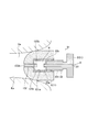
- FIG. 2 is a cross-sectional view for explaining the configuration of the earplug.
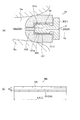
- 3A and 3B are cross-sectional views for explaining the first adjustment state of the earplug, where FIG. 3A is a diagram showing a state where the earplug in the first adjustment state is inserted into the ear canal Ea, and FIG. It is a model figure of the ventilation path in an adjustment state.
- FIG. 3A is a diagram showing a state where the earplug in the first adjustment state is inserted into the ear canal Ea
- FIG. It is a model figure of the ventilation path in an adjustment state.
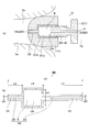
- FIG. 4 is a cross-sectional view for explaining the second adjustment state of the earplug, where (a) is a diagram showing a state in which the earplug in the second adjustment state is inserted into the external auditory meatus Ea, and (b) is a second view. It is a model figure of the ventilation path in an adjustment state.
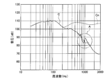
- FIG. 5 is a graph of frequency characteristics for explaining the sound pressure reducing action of the earplugs.
- FIG. 6 is an enlarged view of part A in FIG.
- FIG. 7 is sectional drawing for demonstrating the earplug which concerns on a modification.
- FIG. 1 is a perspective view showing the outer appearance of the earplug 51 according to this embodiment.
- the earplug 51 has a main body 1 and an adjusting unit 2 that is attached (inserted) to the main body 1.
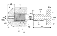
- FIG. 2 is a cross-sectional view for explaining the configuration of the earplug 51, and is an assembly view showing a state before the adjusting portion 2 is screwed into the main body portion 1.
- the main body portion 1 has a base portion 12 and a cushion portion 11.
- the base portion 12 has a tubular air chamber portion 121 whose one end is open, and a tubular duct portion 122 extending from the other end of the air chamber portion 121 along its axis.
- the inner peripheral surface of the air chamber portion 121 has a female screw portion 121a in which a female screw is formed.
- the duct part 122 has a through hole 122a having one end communicating with the internal space of the air chamber part 121 and the other end communicating with the external space Vg.
- the inner diameter of the air chamber portion 121 is defined as the inner diameter (first inner diameter) da1.
- the inner diameter of the female screw portion 121a is the inner diameter da1.
- the inner diameter (second inner diameter) da2 of the through hole 122a is set smaller than the inner diameter da1 of the air chamber portion 121.
- the base 12 is made of resin or metal.
- the resin is, for example, PC (polycarbonate).
- the metal is, for example, aluminum.
- the cushion portion 11 has, for example, a substantially columnar outer shape that extends in the axial direction.
- the cushion portion 11 is made of a flexible material.
- the material is, for example, a sponge made of chloroprene rubber or the like, or a thermoplastic elastomer.
- the cushion portion 11 is fitted and integrated with the base portion 12.
- the cushion portion 11 is formed of a thermoplastic elastomer, the cushion portion 11 is integrally formed by using the base portion 12 as a resin.
- the adjustment unit 2 has a disc-shaped picking portion 21 and a cylindrical screwing portion 22 projecting from the picking portion 21 on its axis.
- the adjustment unit 2 is made of resin or metal.
- the resin is, for example, PC (polycarbonate).
- the metal is, for example, aluminum.
- the picking portion 21 is a portion to be picked by a finger, and a knurl 21a for preventing slippage is formed on the outer peripheral surface.
- the screwing portion 22 has a male screw portion 221. On the outer peripheral surface of the male screw portion 221, a screw thread forming a male screw is formed. Therefore, the male screw portion 221 can be screwed into the female screw portion 121 a of the base portion 12 of the main body 1.
- the adjusting part 2 has a through hole 23 penetrating both ends on the axis.
- the adjusting unit 2 has the through hole 23 that penetrates the adjusting unit 2 in the axial direction.
- the inner diameter (third inner diameter) da3 of the through hole 23 is set smaller than the inner diameter da1 of the air chamber portion 121.
- the inner diameter da3 of the through hole 23 is set to a value closer to the inner diameter da2 of the through hole 122a in the duct portion 122 than the inner diameter da1 of the air chamber portion 121.
- the inner diameter da3 is the same as the inner diameter da2.
- FIG. 1 shows a state in which the male screw portion 221 of the adjusting portion 2 is screwed halfway with respect to the female screw portion 121 a of the main body 1.
- FIG. 3A shows a state in which the earplug 51 in the first adjustment state is inserted (mounted) in the external auditory meatus Ea.
- the cushion portion 11 is in close contact with the inner wall of the external auditory meatus Ea to seal (close) the external auditory meatus Ea.
- the through hole 23 of the adjusting portion 2 and the through hole 122a of the duct portion 122 of the main body portion 1 are directly concentrically communicated (connected), and the air chamber R (see FIG. 4) is not formed.
- the ventilation path D that connects the external space Vg and the internal space Ve of the external auditory meatus Ea is substantially only one linear ventilation path DA.
- FIG. 3B is a model diagram showing the air passage D in the first adjustment state as the air passage model MA.
- the through hole 122a is referred to as the duct D2
- the through hole 23 is referred to as the duct D3.
- the ventilation path DA has a duct D1 that connects the duct D2 and the duct D3. That is, it can be considered that the earplug 51 has the ventilation path DA including the one duct D1 in the first adjustment state.
- the inner diameter da2 of the through hole 122a and the inner diameter da3 of the through hole 23 are both represented by the same inner diameter da.
- the length of the through hole 122a is L2, the length of the through hole 23 is L3, the volume of the internal space of the through hole 122a is V2, and the volume of the internal space of the through hole 23 is V3. .. Further, the sum of the length L2 and the length L3 is defined as the length LA, and the sum of the volumes V2 and V3 is defined as the volume VA. Therefore, in the air passage model MA, the air passage D shown in FIG. 3 is represented as an air passage DA having an inner diameter da, a length LA(L), and a volume VA.
- FIG. 4A shows a state in which the earplug 51 in the second adjustment state is inserted (mounted) in the external auditory meatus Ea.
- the air chamber R as a cylindrical space is formed between the through hole 122a of the duct part 122 and the through hole 23 of the adjusting part 2.
- FIG. 4B is a model diagram showing the air passage D in the second adjustment state as the air passage model MB.
- the ventilation path D in the second adjusted state includes the air chamber R formed between the duct D2 and the duct D3. That is, the earplugs 51 can be regarded as having the air passage DB configured by the air chamber R being interposed in the middle portion of the air passage DA in the first adjustment state in the second adjustment state.
- the ventilation path DB has a length LB and a volume VB.
- the length LB is the sum of the length LA and the length LR
- the volume VB is It is the sum of the volume VA and the volume VR.
- the earplug 51 may be provided with a movement restricting portion (not shown).
- the movement restricting unit restricts the maximum distance (movable distance) at which the adjusting unit 2 can be screwed (retracted) from the first adjustment state to a predetermined value.
- the state in which the adjustment unit 2 is located at the position regulated by the movement regulation unit is called the maximum adjustment state.
- the ventilation path DB including the air chamber R becomes the ventilation path Dmax having the maximum length L2max and the maximum volume VBmax in the maximum adjustment state.
- the earplugs 51 move the adjusting section 2 forward and backward so that the air passage D has an arbitrary length (from the air passage DA corresponding to the first adjustment state to the air passage Dmax corresponding to the maximum adjustment state ( And a ventilation path DB having a volume corresponding to the length).
- the through hole 122a of the main body 1 serves as one end of the air passage D, and the through hole 23 of the adjusting portion 2 serves as the other end of the air passage D.
- the through hole 122a of the main body 1 communicates with the internal space Ve of the external auditory meatus Ea, and the through hole 23 of the adjusting unit 2 communicates with the external space Vg. Therefore, the ventilation path D communicates between the external space Vg and the internal space Ve of the external auditory meatus Ea, and functions as an acoustic filter for sound transmitted from the external space Vg into the external auditory meatus Ea.
- the volume VR of the air chamber R of the ventilation path D as an acoustic filter and the length LR interlocked with the volume VR can be adjusted by adjusting the axial position of the adjusting unit 2 with respect to the main body 1. Therefore, the user wearing the earplugs 51 can hear the external sound that is attenuated based on the frequency characteristic according to the adjustment position of the adjustment unit 2.
- the through hole 23 serves as an external sound inlet and the through hole 122a serves as an external sound outlet. Since the inner diameter da2 of the through hole 122a is sufficiently smaller than the inner diameter of the external auditory meatus Ea, the sound pressure is reduced in a wide sound range in the audible frequency band. Furthermore, by adjusting the axial position of the adjusting unit 2 with respect to the main body unit 1, the volume VR and the length LR of the air chamber R corresponding to the position can be changed, and the characteristics of the reduced audible frequency band can be changed.
- FIG. 5 is a graph showing the characteristics of the earplug 51 as an acoustic filter. This characteristic is obtained as follows. First, a model ear canal is created as a model corresponding to the ear canal Ea, and a microphone is installed in the model ear canal. In addition, a speaker is arranged outside the model ear canal and at a position facing the model ear canal, and the speaker and the model ear canal are covered with a sound insulation box to acoustically cut off from the outside of the sound insulation box. In this state, the sound in the audible frequency band is swept out from the speaker and picked up by the microphone to obtain the frequency-sound pressure characteristic.
- the frequency-sound pressure characteristic collected without the earplug 51 attached to the model ear canal is called the open ear characteristic Cn.
- the frequency-sound pressure characteristic collected with the earplug 51 mounted on the model external auditory meatus is referred to as earplug characteristic C.
- the earplug characteristic C was acquired every time the axial position of the adjusting section 2 with respect to the main body section 1 was changed stepwise.
- a bare ear characteristic Cn shown by a broken line and an earplug characteristic C shown by a solid line were obtained.
- the bare ear characteristic Cn and the earplug characteristic C show almost no difference between the two companies in the low sound range of about 200 Hz or less, and are shown by a single solid line in FIG.
- the sound pressure exhibited by the earplug characteristic C is reduced as compared with the bare ear characteristic Cn.
- the earplug characteristic C changes the degree of sound pressure attenuation at frequencies near a predetermined (specific) frequency.
- the predetermined frequency is 1 kHz in this example.
- FIG. 6 is an enlarged view of part A in FIG.
- the earplug characteristic C of the earplug 51 in the first adjustment state is represented by the characteristic CMA indicated by the solid line
- the earplug characteristic C in the maximum adjustment state is represented by the characteristic CMM indicated by the chain line.
- the air chamber R is not formed. That is, in this state, the length LR of the air chamber R and the volume VR of the air chamber are 0 (zero).
- the characteristic CMA in the first adjustment state has the maximum feature point PA at a frequency slightly higher than 1 kHz.
- the sound pressure of the feature point PA that has the maximum decreases and turns to the minimum. , Is shown as a feature point PB in the characteristic CMM in the maximum adjustment state.
- the sound pressure difference Ha between the maximum feature point PA and the minimum feature point PB is about 6 dB in the example of FIG.
- a sound pressure difference of 6 dB in the vicinity of 1 kHz, which is highly sensitive to human ears, is sufficient for the user of the earplug 51 to recognize that the sound quality changes. That is, the earplug 51 can change the sound quality heard by the user by adjusting the axial position of the adjusting unit 2.
- the range near 1 kHz corresponds to the range of human voice. Therefore, when the earplug 51 has, for example, the earplug characteristic C, by advancing the adjustment unit 2 toward the inner side of the external auditory meatus Ea, the background sound is reduced and the human voice is relatively emphasized and heard. Can be made easier. Further, by retracting the adjusting unit 2 from the inner side of the ear canal Ea, it is possible to reduce the sound pressure in a wide range including the listening sound pressure in the range corresponding to the human voice. That is, the earplug 51 can be used for various purposes.
- the embodiment is not limited to the above-mentioned configuration, and can be modified without departing from the gist of the present disclosure.
- the earplug 51 has a structure (mechanism) that changes the volume of the air chamber R by advancing and retracting the adjustment unit 2 attached to the main body unit 1 in the axial direction.
- This structure (mechanism) is not limited to the screwing of the main body 1 and the adjusting unit 2, and various structures (mechanisms) can be freely applied.
- the adjusting portion 2 may be provided slidably in the axial direction with respect to the main body portion 1 by engaging the concave portion and the convex portion extending in the axial direction.
- the shape of the air chamber R is not limited to a shape in which the cross section orthogonal to the axial direction is constant.
- the cross-sectional area of the air chamber R orthogonal to the axial direction changes with the movement of the adjusting unit 2 in order to change the characteristic with the movement of the adjusting unit 2. Good.
- the number of air chambers R (the number of stages) is not limited to one stage, and may be provided in multiple stages in the axial direction.
- Markers capable of visually determining the axial position of the adjustment unit 2 with respect to the main body unit 1 may be provided.
- a cut extending in the axial direction may be provided on the outer peripheral surface of the screwing portion 22 of the adjusting unit 2, and a plurality of marks may be formed on the bottom surface of the cut at a predetermined pitch in the axial direction. Thereby, the axial position of the adjustment unit 2 can be grasped by which of the plurality of marks is hidden by the base 12 of the main body 1.
- FIG. 7 is a sectional view for explaining an earplug 51 according to a modification.
- the adjustment unit 2 of the earplug 51 according to the modified example may include a tube 22b provided on the distal end surface 22a.
- the tube 22b opens from the periphery of the through hole 23 with the same diameter as the through hole 23, and projects in the axial direction toward the air chamber R (in other words, the through hole 122a).
- the air chamber portion 121 of the earplug 51 according to the modification may have a tube 122b provided on the bottom surface 121b.
- the pipe 122b opens from the periphery of the through hole 122a with the same diameter as the through hole 122a, and projects in the axial direction toward the air chamber R (in other words, the through hole 23). Only one of the tube 22b and the tube 122b may be provided, or both of them may be provided.
- FIG. 7 shows a state in which the earplug 51 having the tube 22b is put into the external auditory meatus Ea in the second adjustment state.
- the tube 22b protruding from the tip end surface 22a of the adjusting portion 2 serves as an inner duct in the air chamber R, and exhibits the sound reducing effect of the muffler.
- the tip of the tube 22b in the first adjustment state comes into contact with the bottom surface 121b of the air chamber portion 121, and the adjustment section 2 is in the deepest state.
- the through hole 23 of the adjusting section 2 is directly concentrically communicated with the through hole 122a of the duct section 122 of the main body section 1, and the air chamber R is not formed. That is, the ventilation path D that connects the external space Vg and the internal space Ve of the external auditory meatus Ea is substantially only one straight ventilation path DA.
Landscapes
- Health & Medical Sciences (AREA)
- Life Sciences & Earth Sciences (AREA)
- Biomedical Technology (AREA)
- Acoustics & Sound (AREA)
- Biophysics (AREA)
- Otolaryngology (AREA)
- Psychology (AREA)
- Engineering & Computer Science (AREA)
- Physics & Mathematics (AREA)
- Heart & Thoracic Surgery (AREA)
- Vascular Medicine (AREA)
- Animal Behavior & Ethology (AREA)
- General Health & Medical Sciences (AREA)
- Public Health (AREA)
- Veterinary Medicine (AREA)
- Headphones And Earphones (AREA)
- Soundproofing, Sound Blocking, And Sound Damping (AREA)
Abstract
耳栓(51)は、一端部が開放された第1の内径(da1)の気室部(121)と、第1の内径(da1)よりも小さい第2の内径(da2)の第1の貫通孔(122a)を有して気室部(121)の他端部から突出するダクト部(122)と、を有し外耳道(Ea)に装着可能な本体部(1)と、第1の内径(da1)よりも小さい第3の内径(da3)の第2の貫通孔(23)を有し、本体部(1)の気室部(121)に軸線方向に移動可能に装着される調整部(2)と、を備える。
Description
本開示は、耳栓に関する。
特許文献1は、音道通路を有する耳栓を記載している。音道通路には、通路面積が拡開する拡開空間部が複数段設けられている。
耳栓の用途は多様であり、音圧低減に関して耳栓に望まれる周波数特性は、その用途によって異なる。例えば大音量のコンサート会場などでは、聴取可能な音の周波数帯域全体の音量を低減する周波数特性が求められ、工事現場などの大騒音環境下では、相対的に、人の声以外の帯域の音圧を低減する周波数特性が望まれる。特許文献1に記載された耳栓は、音圧低減後の周波数特性が固定されるため、多様な用途に用いることが難しい。
実施形態は、多様な用途に使用可能な耳栓を提供することにある。
実施形態の一態様によれば、一端部が開放された第1の内径の気室部と、前記第1の内径よりも小さい第2の内径の第1の貫通孔を有して前記気室部の他端部から突出するダクト部と、を有し外耳道に装着可能な本体部と、前記第2の内径よりも小さい第3の内径の第2の貫通孔を有し、前記本体部の前記気室部に対し前記一端部の側から軸方向に移動可能に装着される調整部と、を備えた耳栓が提供される。
実施形態によれば、多様な用途に使用できる、という効果が得られる。
本開示の実施形態に係る耳栓について説明する。図1は、本実施形態に係る耳栓51の外観を示す斜視図である。耳栓51は、本体部1及び本体部1に装着(挿着)される調整部2を有する。図2は耳栓51の構成を説明するための断面図であり、本体部1に調整部2が螺合する前の状態を示した組立図である。
図1及び図2に示されるように、本体部1は、基部12及びクッション部11を有する。基部12は、一端部が開放された筒状の気室部121と、気室部121の他端部からその軸線上に延びる筒状のダクト部122とを有する。気室部121の内周面は、雌ねじが形成された雌ねじ部121aを有する。ダクト部122は、一端側が気室部121の内部空間と連通し、他端部が外部空間Vgに連通する貫通孔122aを有する。気室部121の内径を内径(第1の内径)da1とする。この例では、雌ねじ部121aの内径が内径da1である。貫通孔122aの内径(第2の内径)da2は、気室部121の内径da1よりも小さく設定される。
基部12は、樹脂又は金属で形成される。樹脂は、例えばPC(ポリカーボネート)である。金属は、例えばアルミニウムである。
クッション部11は、例えば、軸方向に延びる略円柱状の外形を有する。クッション部11は、柔軟性を有する材料で形成されている。材料は、例えば、クロロプレンゴムなどによるスポンジ、又は熱可塑性エラストマである。クッション部11がスポンジで形成される場合、クッション部11は基部12に対して嵌め合いで一体化される。クッション部11が熱可塑性エラストマで形成される場合、基部12を樹脂として一体成形によって形成される。
図1及び図2に示されるように、調整部2は、円盤状の摘み部21と、摘み部21からその軸線上に突出した円柱状の螺合部22とを有する。調整部2は、樹脂又は金属で形成される。樹脂は、例えばPC(ポリカーボネート)である。金属は、例えばアルミニウムである。摘み部21は指で摘まれる部位であり、外周面には、すべり止めのためのローレット21aが形成されている。螺合部22は、雄ねじ部221を有する。雄ねじ部221の外周面には、雄ねじを構成するねじ山が形成されている。従って、雄ねじ部221は、本体部1における基部12の雌ねじ部121aに螺合可能である。調整部2は、軸線上に両端を貫通する貫通孔23を有する。換言すれば、調整部2は、軸方向に調整部2を貫通する貫通孔23を有する。貫通孔23の内径(第3の内径)da3は、気室部121の内径da1よりも小さく設定される。貫通孔23の内径da3は、気室部121の内径da1よりもダクト部122における貫通孔122aの内径da2に近い値とされる。例えば、内径da3は、内径da2と同じとされる。
調整部2は、図2の矢印DRaに示す方向に、本体部1における基部12の気室部121に螺合(装着)される。図1は、調整部2の雄ねじ部221が、本体部1の雌ねじ部121aに対し、途中まで螺進させた状態を示している。
本体部1に螺合した調整部2を螺進させると、螺合部22の先端面22aが、本体部1の気室部121の底面121bに当接する。この当接によって、調整部2の螺進が規制される。
先端面22aが底面121bに当接し、調整部2が最も奥まで進入した耳栓51の状態を、第1調整状態と称する。図3(a)は、第1調整状態の耳栓51が外耳道Eaに挿入(装着)された状態を示している。第1調整状態では、クッション部11が外耳道Eaの内壁に密着し、外耳道Eaを密閉(閉塞)する。また、調整部2の貫通孔23と本体部1のダクト部122における貫通孔122aとが同心で直接連通(接続)し、気室R(図4参照)は形成されない。外部空間Vgと外耳道Eaの内部空間Veとを連通する通気路Dは、実質一本の直線状の通気路DAのみとなる。
図3(b)は、第1調整状態の通気路Dを、通気路モデルMAとして示したモデル図である。なお、貫通孔122aをダクトD2、貫通孔23をダクトD3とする。第1調整状態で、通気路DAは、ダクトD2とダクトD3とを連結したダクトD1を有する。すなわち、耳栓51は、第1調整状態において一本のダクトD1からなる通気路DAを有する、と見なすことができる。ここで、貫通孔122aの内径da2及び貫通孔23の内径da3を何れも同一の内径daで表す。また、貫通孔122aの長さを長さL2、貫通孔23の長さを長さL3とし、貫通孔122aの内部空間の容積を容積V2、貫通孔23の内部空間の容積を容積V3とする。また、長さL2と長さL3の和を長さLAとし、容積V2と容積V3の和を容積VAとする。従って、通気路モデルMAでは、図3に示す通気路Dは、内径da、長さLA(L)、および容積VAを有する通気路DAとして表される。
第1調整状態から調整部2を螺退(後退)させて、気室部121の内部に気室Rを形成した耳栓51の状態を第2調整状態と称する。即ち、第2調整状態では、調整部2の先端面22aが気室部121の底面121bに当接していない。図4(a)は、第2調整状態の耳栓51が外耳道Eaに挿入(装着)された状態を示している。第2調整状態では、ダクト部122の貫通孔122aと調整部2の貫通孔23との間に、円柱状の空間としての気室Rが形成される。この気室Rの内径は、貫通孔23及び貫通孔122aの内径よりも大きい。図4(b)は、第2調整状態の通気路Dを、通気路モデルMBとして示したモデル図である。上述の通り、第2調整状態の通気路DはダクトD2とダクトD3との間に形成された気室Rを含む。すなわち、耳栓51は、第2調整状態において、第1調整状態の通気路DAの中間部位に気室Rが介在することによって構成される通気路DBを有するもの、と見なすことができる。
通気路DBは、長さLB及び容積VBを有する。ここで、気室Rの軸方向の長さを長さLRとし、気室Rの容積を容積VRとすると、長さLBは、長さLAと長さLRの和であり、容積VBは、容積VAと容積VRの和となる。
耳栓51には移動規制部(図示せず)を設けてもよい。移動規制部は、第1調整状態から調整部2を螺退(後退)可能な最大距離(移動可能距離)を、所定の値に規制する。この場合、調整部2が移動規制部によって規制された位置に位置する状態を最大調整状態と称する。気室Rを含む通気路DBは、最大調整状態において、最大の長さL2max及び最大の容積VBmaxを有する通気路Dmaxとなる。
すなわち、耳栓51は、調整部2を進退させることにより、通気路Dを、第1調整状態に対応した通気路DAから最大調整状態に対応した通気路Dmaxまでの間の任意の長さ(及び当該長さに対応する容積)の通気路DBとして調整できる。
本体部1の貫通孔122aは通気路Dの一方の端部となり、調整部2の貫通孔23は通気路Dの他方の端部となる。クッション部11を外耳道Eaに挿入した状態で、本体部1の貫通孔122aは外耳道Eaの内部空間Veに連通し、調整部2の貫通孔23は外部空間Vgに連通する。従って、通気路Dは、外部空間Vgと外耳道Eaの内部空間Veとの間を連通し、外部空間Vgから外耳道Ea内へ伝達する音の音響フィルタとして機能する。一方、耳栓51は、音響フィルタとしての通気路Dの気室Rの容積VR及び容積VRに連動した長さLRを、本体部1に対する調整部2の軸方向位置の調整によって調整できる。そのため、耳栓51を装着した使用者は、調整部2の調整位置に応じた周波数特性に基づいて減衰した外部の音を聴取できる。
通気路Dにおいて、貫通孔23は外部音の入口となり、貫通孔122aは外部音の出口となる。貫通孔122aの内径da2は、外耳道Eaの内径よりも十分に小さいので、可聴周波数帯域における広範囲の音域において音圧が低減される。さらに、本体部1に対する調整部2の軸方向位置を調整することで、その位置に対応した気室Rの容積VR及び長さLRを変え、低減した可聴周波数帯域の特性を変えることができる。
図5は、耳栓51の音響フィルタとしての特性を示すグラフである。この特性は、次のようにして取得する。まず、外耳道Eaに相当する模型としてモデル外耳道を作成し、モデル外耳道内にマイクロフォンを設置する。また、モデル外耳道の外部であって且つモデル外耳道に対向する位置にスピーカを配置し、さらに、スピーカ及びモデル外耳道を遮音箱で覆って音響的に遮音箱の外部と遮断する。この状態で、スピーカから可聴周波数帯域の音をスイープ出力してマイクロフォンで収音し、周波数-音圧特性を得る。
上述の収音において、モデル外耳道に耳栓51を装着しない状態で収音した周波数-音圧特性を、裸耳(open ear)特性Cnと称する。また、モデル外耳道に耳栓51を装着した状態で収音した周波数-音圧特性を、耳栓特性Cと称する。耳栓特性Cは、調整部2の本体部1に対する軸方向位置を段階的に変える度に取得された。
図5に示されるように、破線で示す裸耳特性Cn及び実線で示す耳栓特性Cが得られた。裸耳特性Cn及び耳栓特性Cは、約200Hz以下の低音域での両社の差はほとんど認められず、図5では一本の実線で示されている。一方、200Hzを超える帯域で、耳栓特性Cが示す音圧は、裸耳特性Cnに対して低減されている。
また、本体部1に対する調整部2の軸方向の位置を変えると、耳栓特性Cは、所定の(特定の)周波数付近の周波数において音圧の減衰程度が変化する。所定の周波数はこの例において1kHzである。
図6を参照して、調整部2の位置に応じた耳栓特性Cの変化について詳述する。図6は、図5におけるA部の拡大図である。図6において、耳栓51の第1調整状態での耳栓特性Cが実線で示す特性CMAで表され、最大調整状態での耳栓特性Cが鎖線で示す特性CMMで表されている。
第1調整状態では、気室Rが形成されていない。即ち、この状態では、気室Rの長さLR及び気室の容積VRが0(ゼロ)である。第1調整状態の特性CMAは、1kHzよりもわずかに高い周波数で極大の特徴点PAを有する。第1調整状態から、調整部2を退行させることによって気室Rの長さLR及び気室Rの容積VRが増加するに従い、極大を呈した特徴点PAの音圧は減少して極小に転じ、最大調整状態の特性CMMにおいて特徴点PBとして示される。
極大の特徴点PAと極小の特徴点PBとの音圧差Haは、図6の例において、約6dBである。人の耳として聴取感度の高い1kHz付近における6dBの音圧差は、耳栓51の使用者にとって、音質が変わることを認識するためには十分である。すなわち、耳栓51は、調整部2の軸方向位置を調整することによって使用者に聴取される音質を変えることができる。
1kHz付近の音域は、人の声の音域に対応している。そのため、耳栓51が、例えば耳栓特性Cを有する場合、調整部2を外耳道Eaの奥側へ向けて進行させることで、背景音を低減させつつ人の声を相対的に強調して聞こえ易くすることができる。また、調整部2を外耳道Eaの奥側から退行させることで、人の声に対応した音域の聴取音圧を含む広範囲の音域の音圧を低減させることができる。つまり、耳栓51は多様な用途に使用可能である。
実施形態は、上述の構成に限定されるものではなく、本開示の要旨を逸脱しない範囲で変形可能である。
耳栓51は、本体部1に対し装着された調整部2を軸方向に進退させて気室Rの容積を変える構造(仕組み)を有する。この構造(仕組み)は、本体部1と調整部2の螺合に限定されず、種々の構造(仕組み)を自由に適用できる。例えば、軸方向に延びる凹部と凸部との係合により、本体部1に対して調整部2を軸方向にスライド可能に設けてもよい。気室Rの形状は、軸方向に直交する断面の形状が一定のものに限定されない。例えば、耳栓特性Cにおいて、調整部2の移動に伴う特性変化を所望のものとするために、調整部2の移動に伴って、軸方向に直交する気室Rの断面積が変化してもよい。
気室Rの数(段数)は、一段に限定されず、軸方向に多段に設けてもよい。本体部1に対する調整部2の軸方向位置を視認判別できるマーカ類を設けてもよい。例えば、調整部2の螺合部22の外周面に、軸方向に延びる切り込みを設けると共に切り込みの底面に、軸方向に所定ピッチで複数のマークを形成してもよい。これにより、複数のマークのどれが本体部1の基部12によって隠れているかで、調整部2の軸方向の位置を把握できる。
図7は、変形例に係る耳栓51を説明するための断面図である。図7に示されるように、変形例に係る耳栓51の調整部2は、先端面22aに設けられる管22bを有してもよい。管22bは、貫通孔23の周囲から貫通孔23と同径で開口し、気室R(換言すれば貫通孔122a)に向かって軸方向に突出する。また、図7中の点線で示すように、変形例に係る耳栓51の気室部121は、底面121bに設けられる管122bを有してもよい。管122bは、貫通孔122aの周囲から貫通孔122aと同径で開口し、気室R(換言すれば貫通孔23)に向かって軸方向に突出する。管22bと管122bはいずれか一方のみ設けられてもよく、両方設けられてもよい。例えば、図7は、管22bを有した耳栓51を第2調整状態にして外耳道Eaに挿入した状態を示している。図7において、調整部2の先端面22aより突出した管22bは気室Rにおける内ダクトとなり消音器の減音効果を発揮する。
先端面22aに管22bが設けられる場合、第1調整状態における管22bの先端は、気室部121の底面121bに当接し、調整部2が最も奥まで進入した状態となる。この第1調整状態では、調整部2の貫通孔23が、本体部1のダクト部122における貫通孔122aと同心で直接連通し、気室Rは形成されない。つまり、外部空間Vgと外耳道Eaの内部空間Veとを連通する通気路Dは、実質的に一本の直線状の通気路DAのみとなる。
本願の開示は、2018年12月12日に出願された特願2018-232371号に記載の主題と関連しており、それらの全ての開示内容は引用によりここに援用される。
1 本体部
11 クッション部
12 基部
121 気室部
121a 雌ねじ部
121b 底面
122 ダクト部
122a 貫通孔
122b 菅
2 調整部
21 摘み部
21a ローレット
22 螺合部
22a 先端面
22b 管
221 雄ねじ部
23 貫通孔
51 耳栓
C 耳栓特性、 CMA,CMM 特性、 Cn 裸耳特性
da,da1,da2,da3 内径
Ea 外耳道
MA,MB 通気路モデル
DA,D,DB,Dmax 通気路、 D1,D2,D3 ダクト
Ha 音圧差
L,LA,L2,L3,LR,LB,L2max 長さ
MA,MB 通気路モデル、 PA,PB 特徴点
R 気室
Ve 外耳道の内部空間、 Vg 外部空間
V2,V3,VA,VR,VB,VBmax 容積
11 クッション部
12 基部
121 気室部
121a 雌ねじ部
121b 底面
122 ダクト部
122a 貫通孔
122b 菅
2 調整部
21 摘み部
21a ローレット
22 螺合部
22a 先端面
22b 管
221 雄ねじ部
23 貫通孔
51 耳栓
C 耳栓特性、 CMA,CMM 特性、 Cn 裸耳特性
da,da1,da2,da3 内径
Ea 外耳道
MA,MB 通気路モデル
DA,D,DB,Dmax 通気路、 D1,D2,D3 ダクト
Ha 音圧差
L,LA,L2,L3,LR,LB,L2max 長さ
MA,MB 通気路モデル、 PA,PB 特徴点
R 気室
Ve 外耳道の内部空間、 Vg 外部空間
V2,V3,VA,VR,VB,VBmax 容積
Claims (4)
- 一端部が開放された第1の内径の気室部と、前記第1の内径よりも小さい第2の内径の第1の貫通孔を有して前記気室部の他端部から突出するダクト部と、を有し外耳道に装着可能な本体部と、
前記第1の内径よりも小さい第3の内径の第2の貫通孔を有し、前記本体部の前記気室部に軸方向に移動可能に装着される調整部と、を備えた耳栓。 - 前記調整部の先端面が前記気室部の底面に当接した状態で、前記第1の貫通孔と前記第2の貫通孔とが直接連通した通気路が形成されることを特徴とする請求項1記載の耳栓。
- 前記調整部の先端面が前記気室部の底面に当接していない状態で、前記第1の貫通孔と、前記第2の貫通孔と、前記第1の貫通孔と前記第2の貫通孔との間に介在する前記気室部の一部からなる気室と、からなる通気路が形成されることを特徴とする請求項1又は請求項2記載の耳栓。
- 前記調整部は、前記気室部に対し螺合して軸方向に移動可能とされていることを特徴とする請求項1~3のいずれか1項に記載の耳栓。
Priority Applications (2)
| Application Number | Priority Date | Filing Date | Title |
|---|---|---|---|
| CN201980073021.7A CN113038912B (zh) | 2018-12-12 | 2019-12-05 | 耳塞 |
| JP2020560000A JP7074207B2 (ja) | 2018-12-12 | 2019-12-05 | 耳栓 |
Applications Claiming Priority (2)
| Application Number | Priority Date | Filing Date | Title |
|---|---|---|---|
| JP2018-232371 | 2018-12-12 | ||
| JP2018232371 | 2018-12-12 |
Publications (1)
| Publication Number | Publication Date |
|---|---|
| WO2020121936A1 true WO2020121936A1 (ja) | 2020-06-18 |
Family
ID=71076988
Family Applications (1)
| Application Number | Title | Priority Date | Filing Date |
|---|---|---|---|
| PCT/JP2019/047595 Ceased WO2020121936A1 (ja) | 2018-12-12 | 2019-12-05 | 耳栓 |
Country Status (3)
| Country | Link |
|---|---|
| JP (1) | JP7074207B2 (ja) |
| CN (1) | CN113038912B (ja) |
| WO (1) | WO2020121936A1 (ja) |
Families Citing this family (1)
| Publication number | Priority date | Publication date | Assignee | Title |
|---|---|---|---|---|
| CN114845222B (zh) * | 2022-04-25 | 2025-07-08 | 歌尔股份有限公司 | 发声装置和终端设备 |
Citations (1)
| Publication number | Priority date | Publication date | Assignee | Title |
|---|---|---|---|---|
| US2881759A (en) * | 1956-12-10 | 1959-04-14 | Robert W Hocks | Ear protector |
Family Cites Families (5)
| Publication number | Priority date | Publication date | Assignee | Title |
|---|---|---|---|---|
| CN100544688C (zh) * | 2004-06-18 | 2009-09-30 | 刘月明 | 耳塞及应用该耳塞的装置 |
| DE202007016881U1 (de) * | 2007-12-03 | 2009-04-09 | Sennheiser Electronic Gmbh & Co. Kg | Hörer |
| JP5363825B2 (ja) * | 2009-02-04 | 2013-12-11 | 株式会社オーディオテクニカ | ノイズキャンセルヘッドホン |
| WO2017169133A1 (ja) * | 2016-03-29 | 2017-10-05 | 富士フイルム株式会社 | イヤーマフ |
| NL2018029B1 (en) * | 2016-12-20 | 2018-06-28 | Dynamic Ear Company B V | Earplug and method for attenuating sound |
-
2019
- 2019-12-05 JP JP2020560000A patent/JP7074207B2/ja active Active
- 2019-12-05 WO PCT/JP2019/047595 patent/WO2020121936A1/ja not_active Ceased
- 2019-12-05 CN CN201980073021.7A patent/CN113038912B/zh active Active
Patent Citations (1)
| Publication number | Priority date | Publication date | Assignee | Title |
|---|---|---|---|---|
| US2881759A (en) * | 1956-12-10 | 1959-04-14 | Robert W Hocks | Ear protector |
Also Published As
| Publication number | Publication date |
|---|---|
| JP7074207B2 (ja) | 2022-05-24 |
| CN113038912A (zh) | 2021-06-25 |
| JPWO2020121936A1 (ja) | 2021-09-27 |
| CN113038912B (zh) | 2023-10-24 |
Similar Documents
| Publication | Publication Date | Title |
|---|---|---|
| US4852683A (en) | Earplug with improved audibility | |
| US9088846B2 (en) | Oval variable wall earbud | |
| US6629579B1 (en) | Headphones/earmuffs | |
| US7681577B2 (en) | Ear tip | |
| KR100969750B1 (ko) | 이어패드 및 상기 패드를 갖춘 이어폰 | |
| US8550206B2 (en) | Method and structure for achieving spectrum-tunable and uniform attenuation | |
| JP5356399B2 (ja) | イヤホン装置 | |
| US5113967A (en) | Audibility earplug | |
| JP5271412B2 (ja) | 非ロール型フォームイヤーチップ | |
| US4055233A (en) | Ear coupler | |
| JP7100208B2 (ja) | イヤピース | |
| US8573353B2 (en) | Long-wearing deep-insertion ear tip | |
| KR101831575B1 (ko) | 회선형 음향 혼을 가진 청력 보호 장치 | |
| US20170188128A1 (en) | Noise reduction with in-ear headphone | |
| US20200221201A1 (en) | Ear tip sealing structure | |
| US20080085030A1 (en) | Inconspicuous communications assembly | |
| CN107864418A (zh) | 入耳式有源噪声降低耳机 | |
| TW201338565A (zh) | 骨傳導耳機 | |
| CN202587329U (zh) | 入耳式耳机 | |
| CN113810813B (zh) | 耳机本体、耳机及使用耳机本体调整声压级的方法 | |
| US20100071708A1 (en) | Novel hearing protection device and method and secure earbud assembly | |
| US8107638B2 (en) | Semi-insert hearing protector having a helmholtz-type resonator | |
| JP7074207B2 (ja) | 耳栓 | |
| JP7439885B2 (ja) | 耳栓 | |
| WO2023005110A1 (zh) | 耳机结构 |
Legal Events
| Date | Code | Title | Description |
|---|---|---|---|
| 121 | Ep: the epo has been informed by wipo that ep was designated in this application |
Ref document number: 19895934 Country of ref document: EP Kind code of ref document: A1 |
|
| ENP | Entry into the national phase |
Ref document number: 2020560000 Country of ref document: JP Kind code of ref document: A |
|
| NENP | Non-entry into the national phase |
Ref country code: DE |
|
| 122 | Ep: pct application non-entry in european phase |
Ref document number: 19895934 Country of ref document: EP Kind code of ref document: A1 |