WO2020121911A1 - Positioning pin - Google Patents
Positioning pin Download PDFInfo
- Publication number
- WO2020121911A1 WO2020121911A1 PCT/JP2019/047396 JP2019047396W WO2020121911A1 WO 2020121911 A1 WO2020121911 A1 WO 2020121911A1 JP 2019047396 W JP2019047396 W JP 2019047396W WO 2020121911 A1 WO2020121911 A1 WO 2020121911A1
- Authority
- WO
- WIPO (PCT)
- Prior art keywords
- pin body
- pin
- positioning pin
- axial direction
- jig
- Prior art date
Links
- 238000003780 insertion Methods 0.000 description 12
- 230000037431 insertion Effects 0.000 description 12
- 230000002093 peripheral effect Effects 0.000 description 5
- 238000001179 sorption measurement Methods 0.000 description 4
- 238000000034 method Methods 0.000 description 3
- 230000000694 effects Effects 0.000 description 2
- 230000000740 bleeding effect Effects 0.000 description 1
- 239000000696 magnetic material Substances 0.000 description 1
- 230000004048 modification Effects 0.000 description 1
- 238000012986 modification Methods 0.000 description 1
Images


Classifications
-
- F—MECHANICAL ENGINEERING; LIGHTING; HEATING; WEAPONS; BLASTING
- F16—ENGINEERING ELEMENTS AND UNITS; GENERAL MEASURES FOR PRODUCING AND MAINTAINING EFFECTIVE FUNCTIONING OF MACHINES OR INSTALLATIONS; THERMAL INSULATION IN GENERAL
- F16B—DEVICES FOR FASTENING OR SECURING CONSTRUCTIONAL ELEMENTS OR MACHINE PARTS TOGETHER, e.g. NAILS, BOLTS, CIRCLIPS, CLAMPS, CLIPS OR WEDGES; JOINTS OR JOINTING
- F16B19/00—Bolts without screw-thread; Pins, including deformable elements; Rivets
- F16B19/02—Bolts or sleeves for positioning of machine parts, e.g. notched taper pins, fitting pins, sleeves, eccentric positioning rings
-
- F—MECHANICAL ENGINEERING; LIGHTING; HEATING; WEAPONS; BLASTING
- F16—ENGINEERING ELEMENTS AND UNITS; GENERAL MEASURES FOR PRODUCING AND MAINTAINING EFFECTIVE FUNCTIONING OF MACHINES OR INSTALLATIONS; THERMAL INSULATION IN GENERAL
- F16B—DEVICES FOR FASTENING OR SECURING CONSTRUCTIONAL ELEMENTS OR MACHINE PARTS TOGETHER, e.g. NAILS, BOLTS, CIRCLIPS, CLAMPS, CLIPS OR WEDGES; JOINTS OR JOINTING
- F16B21/00—Means for preventing relative axial movement of a pin, spigot, shaft or the like and a member surrounding it; Stud-and-socket releasable fastenings
- F16B21/10—Means for preventing relative axial movement of a pin, spigot, shaft or the like and a member surrounding it; Stud-and-socket releasable fastenings by separate parts
- F16B21/16—Means for preventing relative axial movement of a pin, spigot, shaft or the like and a member surrounding it; Stud-and-socket releasable fastenings by separate parts with grooves or notches in the pin or shaft
- F16B21/18—Means for preventing relative axial movement of a pin, spigot, shaft or the like and a member surrounding it; Stud-and-socket releasable fastenings by separate parts with grooves or notches in the pin or shaft with circlips or like resilient retaining devices, i.e. resilient in the plane of the ring or the like; Details
Definitions
- the present disclosure relates to a positioning pin.
- an assembly jig may be used to position the parts/members that make up the aircraft.
- the assembly jig may be combined into a single assembly jig.
- the plurality of jigs may be fixed by a fastening member such as a hand knob.
- ⁇ It is necessary to position the jigs as a pre-process before fixing the jigs with the fastening members.
- the jigs are positioned by, for example, positioning pins inserted into the plurality of jigs.
- Patent Document 1 discloses a stop pin that is not a positioning pin used for the above-mentioned applications, but that prevents the bucket attached to the fork of a forklift from coming off.
- Positioning the jig with the positioning pin has the following problems. For example, depending on the orientation of the positioning pin, the positioning pin may fall off the jig due to its own weight. Further, regardless of the orientation of the positioning pin, the positioning pin may fall out of the jig due to, for example, vibration during driving. In addition, when there is no through hole for air bleeding in the hole of the jig (the hole formed in the jig) into which the positioning pin is inserted (that is, when it is a bottomed hole), it is sealed inside the hole and compressed. There is a possibility that the positioning pin is pushed back by the air that has been blown.
- an annular magnet is attached to the end opposite to the tip inserted into the sleeve through a seat plate, a screw, and a coil spring. Since the retaining pin is attracted to the receiving side by the annular magnet, it does not easily come off due to vibration or the like.
- the present disclosure has been made in view of such circumstances, and the present disclosure does not easily fall off from the jig due to its own weight acting on the positioning pin, vibration, and the force that pushes back the positioning pin, and the operator can easily It is an object of the present invention to provide a removable positioning pin.
- the positioning pin of the present disclosure adopts the following means. That is, the positioning pin according to one aspect of the present disclosure includes a pin body that is inserted into the jig from the tip in the axial direction, and a suction body that the pin body is inserted in the axial direction and is adsorbed to the jig. A member and a fixing member that is fixed to the pin body and fixes the suction member to the pin body in the axial direction, wherein the suction member and the fixing member are the pin body in the axial direction. It is located in the middle part of.
- the pin body in which the suction member is fixed in the axial direction by the fixing member is inserted into the jig.
- the adsorption member adsorbs to the jig.
- the positioning pin inserted in the jig is adsorbed to the jig via the adsorbing member. Since the positioning pin is attracted to the jig, the positioning pin does not easily fall off from the jig due to its own weight, vibration, and force for pushing back the positioning pin.
- the suction member and the fixing member are arranged at an intermediate portion in the axial direction of the pin body.
- a section where the suction member and the fixing member are not arranged is formed between the base end (the end opposite to the tip of the pin body inserted into the jig) and the intermediate portion.
- the attraction member includes a magnet.
- the attraction member includes a magnet.
- the suction member sticks to the jig.
- a permanent magnet for example, is used as the magnet.
- the fixing member is an annular member that is fitted into the pin body and fixed in the axial direction, and the plurality of annular members that are arranged apart from each other in the axial direction.
- the suction member is sandwiched by.
- the fixing member is an annular member fitted in the pin body, and the suction member is sandwiched by a plurality of (for example, two) annular members that are spaced apart in the axial direction of the pin body.
- the annular member, the suction member, and the annular member are arranged in this order along the axial direction, and the suction member sandwiched between the annular members is sandwiched by the annular members.
- the annular member is fitted into the pin body and fixed in the axial direction. Therefore, the suction member sandwiched between the two annular members is also fixed in the axial direction with respect to the pin body.
- the annular member include a snap ring, and preferably an E ring. When a retaining ring such as an E ring is used, the suction member can be fixed in the axial direction with a simple structure.
- the fixing member is an annular member that is fitted into the pin body and fixed in the axial direction, and the pin body is in contact with the suction member in the axial direction.
- a stepped portion is formed, and the suction member that abuts the stepped portion is sandwiched by the stepped portion and the annular member in the axial direction.
- the fixing member is an annular member fitted in the pin body.
- a stepped portion is formed on the pin body.
- the suction member, through which the pin body is inserted is in contact with the stepped portion.
- the suction member that is in contact with the stepped portion is sandwiched by the stepped portion and the annular member. That is, the stepped portion, the suction member, and the annular member are arranged in this order along the axial direction.
- the annular member is fitted in the pin body and is fixed in the axial direction.
- the stepped portion is formed on the pin body, it is immovable in the axial direction.
- the suction member sandwiched between the stepped portion and the annular member is fixed to the pin body in the axial direction.
- the annular member include a snap ring, and preferably an E ring.
- the suction member can be fixed in the axial direction with a simple structure.
- the positioning pin according to the present disclosure does not easily fall off from the jig due to its own weight acting on the positioning pin, vibration, and the force that pushes back the positioning pin, and the worker can easily remove it.
- FIG. 3 is a side view of the positioning pin according to the first embodiment of the present disclosure.
- FIG. 3 is a side view of the pin body according to the first embodiment of the present disclosure. It is an enlarged view of the A section of FIG. It is a front view of an example (E ring) of an annular member. It is a front view of an adsorption member. It is a front view of the modification of an adsorption member. It is a partial expanded side view which the annular member was fitted in the pin main body shown in FIG.
- FIG. 8 is a partially enlarged side view in which a suction member is fitted to the pin body shown in FIG. 7.
- FIG. 9 is a partially enlarged side view in which an annular member is fitted into the pin body shown in FIG. 8.
- FIG. 14 is a partially enlarged side view of the pin body shown in FIG. 13 in which the suction member is fitted.
- FIG. 15 is a partially enlarged side view in which an annular member is fitted into the pin body shown in FIG. 14.
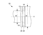
- FIG. 1 shows a side view of the positioning pin 1A.
- the positioning pin 1A includes a pin body 10, a fixing member 20 fitted in the pin body 10, and a suction member 30 fixed to the pin body 10 by the fixing member 20.
- the pin body 10 is a rod-shaped member extending in the direction of the axis X, as shown in FIG.
- the cross section of the pin body 10 is circular.
- One end of the pin main body 10 (the left end shown in the figure) is a tip 10a, which is an end on the side to be inserted into a jig 40 described later.
- the end on the side opposite to the tip 10a (the end on the right side in the figure) is the base end 10b.
- a grip portion 42 is attached to a section of the pin body 10 between the base end 10b and the fixing member 20 arranged on the right side of the suction member 30 in FIG.
- the grip portion 42 is a member that functions as a handle that enables an operator to easily grip the positioning pin 1A.
- the grip portion 42 is a rod-shaped member that extends orthogonal to the axis X when attached to the pin body 10, and forms an L shape together with the pin body 10.
- the grip portion 42 is not limited to the L-shape as shown in FIG. 2, and may be, for example, a T-shape together with the pin body 10.
- the pin body 10 has an enlarged diameter in the middle portion in the direction from the tip 10a to the base 10b along the axis X.
- the outer diameter de on the base end 10b side is larger than the outer diameter dt on the front end 10a side.
- FIG. 3 which is an enlarged view of the portion A of FIG. 2, a groove portion 12A and a groove portion 12B into which a fixing member 20 described later is fitted are separated from each other in the axial direction X in the intermediate portion of the pin body 10. It is formed in the entire circumferential direction from the peripheral side surface of the pin body 10 toward the axis X side.
- the one groove portion 12A is formed on the tip 10a side in the intermediate portion, that is, in the section of the pin body 10 having the outer diameter dt.
- the outer diameter of the groove 12A is smaller than the outer diameter dt on the tip 10a side.
- the other groove portion 12B is formed on the base end 10b side in the intermediate portion, that is, in the section of the pin body 10 having the outer diameter de.
- the outer diameter of the groove portion 12B is smaller than the outer diameter de of the base end 10b side.
- the outer diameter of the groove 12A and the outer diameter of the groove 12B may be the same.
- groove portion 12A and the groove portion 12B are described separately, they are referred to as “groove portion 12A” or “groove portion 12B”, and when there is no need to distinguish them, they are simply referred to as “groove portion 12”.
- a section of the pin body 10 sandwiched between the groove portions 12 in the pin body 10 is a fitting portion 14 into which a suction member 30 described later is fitted.
- the dimensions of the pin body 10 are, for example, approximately as follows. 2 and 3, the distance from the tip 10a to the base 10b is about 50 mm or more and 100 mm or less. The distance from the tip 10a to the groove 12A is about 30 mm or more and 80 mm or less. The outer diameter dt is about 4 mm or more and 15 mm or less. The outer diameter de is about 6 mm or more and 30 mm or less. The outer diameter of the groove 12 is about 3 mm or more and 12 mm or less.
- the fixing member 20 is, for example, an annular member such as a snap ring, and more preferably an E ring as shown in FIG.
- the E-ring is a substantially annular member having an opening in a partial section in the circumferential direction when viewed in a plan view as shown in FIG.
- convex protrusions formed from the inner edge toward the center side are provided at three locations spaced apart in the circumferential direction.
- the E ring is a snap ring having a substantially E shape.
- the outer diameter of the fixing member 20 is larger than the inner diameter of the insertion hole 32 (described later).
- the suction member 30 is an annular member having an insertion hole 32 when viewed from the front.
- the suction member 30 is a member that can be sucked by a jig 40 described later.
- the attraction member 30 can be attracted to the jig 40 by using a magnet such as a permanent magnet for the attraction member 30.
- the inner diameter of the insertion hole 32 corresponds to the outer diameter of the fitting portion 14 formed on the pin body 10 described above. Specifically, the fitting portion 14 can be smoothly inserted into the insertion hole 32 and can be fitted without rattling.
- the suction member 30 is not limited to the annular shape as shown in FIG. 5, and may have a quadrangular shape when viewed from the front as shown in FIG. 6, or may have another shape. Is also good. In short, as long as the insertion hole 32 corresponding to the outer diameter of the fitting portion 14 is formed, the outer shape of the suction member 30 is not particularly limited.
- the pin body 10 is provided with the groove portion 12A, the fitting portion 14, and the groove portion 12B in this order from the tip end 10a to the base end 10b along the axis X.
- a fixing member 20 such as an E ring is fitted into the groove 12B on the base end side from the peripheral side surface side. As a result, the fixing member 20 is fixed to the pin body 10 in the axis X direction.
- the pin body 10 is inserted from the tip end 10a side (the left side in the figure) into the insertion hole 32 formed in the suction member 30 in the axis X direction, and the suction member 30 is inserted. Is fitted into the fitting portion 14 of the pin body 10.
- a fixing member 20 such as an E-ring is fitted into the groove portion 12A on the tip side from the peripheral side surface side. As a result, the fixing member 20 is fixed to the pin body 10 in the axis X direction.
- the positions of the groove portions 12 and the widths of the groove portions 12 and the fixing member 20 are set so that both side surfaces of the suction member 30 in the axis X direction and the side surfaces of the fixing member 20 facing the respective side surfaces come into contact with each other. Width) and the width of the suction member 30 are designed.
- the fixing members 20 fitted in the groove 12A and the groove 12B are fixed in the direction of the axis X, respectively.
- the suction member 30 sandwiched between the two fixing members 20 and whose side surface is in contact with the two fixing members 20 is fixed in the direction of the axis X while being sandwiched between the two fixing members 20.
- the pin body 10 becomes the positioning pin 1A as shown in FIG.
- the above-mentioned positioning pin 1A is used when positioning another jig 40 with respect to one jig 40 as shown in FIG.
- Holes 44 are formed in each of the two jigs 40.
- the inner diameter of the hole 44 corresponds to the outer diameter dt on the tip 10a side of the pin body 10, and the positioning pin 1A can be inserted from the tip 10a side.
- the positioning pin 1A is attached to the axis line X with respect to the holes 44 formed in the two jigs 40.
- the two jigs 40 are positioned by inserting in the direction.
- the fixing member 20 having an outer diameter larger than the inner diameter of the hole 44 contacts the jig 40 without being inserted into the hole 44. As a result, the positioning pin 1A is restrained at a predetermined position in the insertion direction.
- the fixing member 20 that comes into contact with the jig 40 is the fixing member 20 fitted in the groove 12A.
- the suction member 30 fixed to the positioning pin 1A is close to the jig 40, the suction member 30 is attracted to the jig 40.
- the positioning pin 1A is constrained at a predetermined position in the insertion direction by the fixing member 20 that comes into contact with the jig 40, as a result, the positioning pin 1A is attracted to the jig 40 via the attraction member 30. Fixed.
- each member is arranged so that the hand of the worker does not interfere with the fixing member 20 and the suction member 30 when the grip portion 42 is gripped. That is, it is preferable that the intermediate portion where the fixing member 20 and the suction member 30 are arranged is at a position where the hand of the worker who holds the grip portion 42 does not interfere with the fixing member 20 and the suction member 30.
- the positioning pin 1A inserted in the jig 40 is adsorbed to the jig 40 via the adsorbing member 30. Since the positioning pin 1A is attracted to the jig 40, the positioning pin 1A can be easily moved from the jig 40 by its own weight acting when the axis X direction coincides with the vertical direction, external vibration, and force for pushing back the positioning pin. None fall off.
- the suction member 30 and the fixing member 20 are arranged in an intermediate portion in the axial direction of the pin body 10. As a result, a section in which the suction member 30 and the fixing member 20 are not arranged is formed between the base end 10b of the pin body 10 and the intermediate portion.
- the fixing member 20 When a retaining ring such as an E ring is used as the fixing member 20, it is only necessary to form the groove 12 for fitting in the pin body 10, and the suction member 30 can be fixed in the axis X direction with a simple structure.
- a retaining ring such as an E ring
- the positioning pin 1B of the present embodiment is different from the first embodiment in the structure around the suction member 30, but is the same in other respects. Therefore, only the points different from the first embodiment will be described, and other elements will be denoted by the same reference numerals and the description thereof will be omitted.
- FIG. 11 shows a side view of the positioning pin 1A.
- the positioning pin 1B includes a pin body 10, a fixing member 20 fitted in the pin body 10, and a suction member 30 fixed to the pin body 10 by the fixing member 20 and the pin body 10.
- the pin body 10 is a rod-shaped member extending in the direction of the axis X, as shown in FIG.
- One end (the end portion on the left side in the figure) of the pin body 10 is a tip 10a.
- the end on the side opposite to the tip 10a is the base end 10b.
- a grip portion 42 is integrally formed in a section of the pin body 10 between the base end 10b and the suction member 30.
- the grip portion 42 is a member that functions as a handle that allows an operator to easily grip the positioning pin 1B when using it.
- the grip portion 42 may be knurled to form a pattern or groove that imparts a frictional force.
- the pin body 10 is formed with a stepped portion 16 having an enlarged diameter in the middle portion in the direction from the tip 10a to the base 10b along the axis X.
- the outer diameter de from the stepped portion 16 to the base end 10b side is larger than the outer diameter dt on the tip end 10a side and the inner diameter of the insertion hole 32 of the suction member 30.
- FIG. 13 which is an enlarged view of the portion B of FIG. 12, in the section of the pin body 10 having the outer diameter dt, the groove 12 into which the fixing member 20 is fitted is provided with the axis X from the peripheral side surface of the pin body 10. It is formed in the entire circumferential direction toward the side.
- a section of the pin body 10 sandwiched between the stepped portion 16 and the groove portion 12 is a fitting portion 14 into which the suction member 30 is fitted, and corresponds to the inner diameter of the insertion hole 32 formed in the suction member 30. There is.
- the pin body 10 is formed with the groove portion 12, the fitting portion 14, and the stepped portion 16 in this order from the tip end 10a to the base end 10b along the axis X.
- the pin body 10 is inserted from the tip 10a side (the left side in the figure) into the insertion hole 32 formed in the suction member 30 in the axis X direction. Then, the suction member 30 is fitted into the fitting portion 14 of the pin body 10 and is brought into contact with the stepped portion 16.
- a fixing member 20 such as an E-ring is fitted into the groove 12 from the peripheral side surface side.
- the fixing member 20 is fixed to the pin body 10 in the axis X direction.
- the position of the groove portion 12, the width of the fixing member 20, the suction member, and the suction member 30 so that the both side surfaces of the suction member 30 in the axis X direction and the side surfaces of the stepped portion 16 and the fixing member 20 facing the respective side surfaces come into contact with each other.
- the width and the like of the member 30 are designed.
- the stepped portion 16 Since the stepped portion 16 is formed on the pin body 10, it is immovable with respect to the pin body 10. Further, the fixing member 20 fitted in the groove 12 is fixed in the axis X direction. As a result, the suction member 30 sandwiched between the stepped portion 16 and the fixing member 20 and the side surface of which is in contact is fixed in the direction of the axis X while being sandwiched between the stepped portion 16 and the fixing member 20.
- the pin body 10 becomes a positioning pin 1B as shown in FIG.
- the following effects are achieved.
- the number of the fixing member 20 for example, a retaining ring such as an E ring
- the groove portion 12 into which the fixing member 20 is fitted are reduced as compared with the first embodiment. be able to. This makes it possible to reduce the time required to form the groove portion 12, the number of parts, and the cost.
- the first embodiment and the second embodiment can be combined within a possible range.
- the L-shaped gripping portion 42 (see FIG. 1) of the positioning pin 1A according to the first embodiment is similar to the straight-type gripping portion 42 (see FIG. 11) of the positioning pin 1B according to the second embodiment. It may have any shape.
Abstract
Provided is a positioning pin with which the own weight of the positioning pin, vibrations acting on the positioning pin, or a force pushing the positioning pin back do not easily cause the positioning pin to fall out from a jig, and which can be easily detached and attached by an operator. A positioning pin (1) is provided with a pin main body (10) which is inserted in an axial direction from a distal end (10a) thereof into a jig, a suction attachment member (30) through which the pin main body (10) is inserted in the axial direction, and which is suction-attached to the jig, and a fixing member (20) which is fixed to the pin main body (10), and which fixes the suction attachment member (30) to the pin main body (10) in the axial direction, wherein the suction attachment member (30) and the fixing member (20) are disposed on an intermediate part of the pin main body (10) in the axial direction.
Description
本開示は、位置決めピンに関する。
The present disclosure relates to a positioning pin.
例えば、航空機を組み立てる際、航空機を構成する部品・部材を位置決めするために組立用治具を使用することがある。組立用治具は、複数の治具を組み合わせることで1つの組立用治具とする場合がある。このとき、複数の治具は、例えばハンドノブのような締結部材によって固定されることがある。
For example, when assembling an aircraft, an assembly jig may be used to position the parts/members that make up the aircraft. The assembly jig may be combined into a single assembly jig. At this time, the plurality of jigs may be fixed by a fastening member such as a hand knob.
締結部材による治具同士の固定の前工程として、治具同士の位置決めを行う必要がある。このとき、治具同士の位置決めは、例えば複数の治具に対して挿入される位置決めピンによって行われる。
ㆍIt is necessary to position the jigs as a pre-process before fixing the jigs with the fastening members. At this time, the jigs are positioned by, for example, positioning pins inserted into the plurality of jigs.
特許文献1には、前述の用途に用いられる位置決めピンではないが、フォークリフトのフォークに取り付けられるバケットの抜け防止用の止めピンが開示されている。
Patent Document 1 discloses a stop pin that is not a positioning pin used for the above-mentioned applications, but that prevents the bucket attached to the fork of a forklift from coming off.
位置決めピンによる治具の位置決めには、次のような課題がある。例えば、位置決めピンの向きによっては、自重によって位置決めピンが治具から脱落するおそれがある。また、位置決めピンの向きに関係なく、例えば打鋲時の振動などによって位置決めピンが治具から脱落するおそれがある。その他、位置決めピンが挿入される治具の穴(治具に形成された穴)にエア抜き用の貫通孔がない場合(すなわち有底孔とされている場合)、穴の内部に密閉され圧縮された空気によって位置決めピンが押し戻されるおそれがある。
Positioning the jig with the positioning pin has the following problems. For example, depending on the orientation of the positioning pin, the positioning pin may fall off the jig due to its own weight. Further, regardless of the orientation of the positioning pin, the positioning pin may fall out of the jig due to, for example, vibration during driving. In addition, when there is no through hole for air bleeding in the hole of the jig (the hole formed in the jig) into which the positioning pin is inserted (that is, when it is a bottomed hole), it is sealed inside the hole and compressed. There is a possibility that the positioning pin is pushed back by the air that has been blown.
特許文献1に開示されている止めピンにおいて、受ざやに挿入される先端とは反対側の端部に、座板、ネジ、コイルバネを介して環状磁石が取り付けられている。止めピンは、環状磁石によって受ざや側に吸着するので、振動などで簡単に抜け落ちることはない。
In the stop pin disclosed in Patent Document 1, an annular magnet is attached to the end opposite to the tip inserted into the sleeve through a seat plate, a screw, and a coil spring. Since the retaining pin is attracted to the receiving side by the annular magnet, it does not easily come off due to vibration or the like.
しかし、このような構造は複雑であり部品点数が多くコストがかかる。また、取り外しの際、座板と受ざやの間に先の尖った工具を入れてこじ上げればならず、止めピンの脱着性について課題がある。
However, such a structure is complicated, has a large number of parts, and is costly. In addition, at the time of removal, it is necessary to insert a sharp tool between the seat plate and the receiver and pry it up, which poses a problem regarding the detachability of the retaining pin.
本開示はこのような事情に鑑みてなされてものであって、位置決めピンに作用する自重、振動、位置決めピンを押し戻す力によって治具から容易に脱落することがないうえに、作業者が容易に脱着できる位置決めピンを提供することを目的とする。
The present disclosure has been made in view of such circumstances, and the present disclosure does not easily fall off from the jig due to its own weight acting on the positioning pin, vibration, and the force that pushes back the positioning pin, and the operator can easily It is an object of the present invention to provide a removable positioning pin.
上記課題を解決するために、本開示の位置決めピンは以下の手段を採用する。
即ち、本開示の一態様に係る位置決めピンは、治具に対して軸線方向に先端から挿入されるピン本体と、該ピン本体が前記軸線方向に挿通され、前記治具に対して吸着する吸着部材と、前記ピン本体に対して固定され、前記吸着部材を前記ピン本体に対して前記軸線方向に固定する固定部材とを備え、前記吸着部材および前記固定部材は、前記軸線方向において前記ピン本体の中間部分に配置されている。 In order to solve the above problems, the positioning pin of the present disclosure adopts the following means.
That is, the positioning pin according to one aspect of the present disclosure includes a pin body that is inserted into the jig from the tip in the axial direction, and a suction body that the pin body is inserted in the axial direction and is adsorbed to the jig. A member and a fixing member that is fixed to the pin body and fixes the suction member to the pin body in the axial direction, wherein the suction member and the fixing member are the pin body in the axial direction. It is located in the middle part of.
本態様の位置決めピンによれば、固定部材によって吸着部材が軸線方向に固定されたピン本体が治具に挿入される。このとき、吸着部材は治具に対して吸着する。これによって、治具に挿入された位置決めピンは、吸着部材を介して治具に対して吸着する。位置決めピンは治具に吸着するので、位置決めピンは、自重、振動、位置決めピンを押し戻す力によって治具から容易に脱落することがない。
また、吸着部材および固定部材は、ピン本体の軸線方向において中間部分に配置されている。これによって、基端(治具に挿入されるピン本体の先端とは反対側の端部)と中間部分との間には、吸着部材および固定部材は配置されない区間ができる。その基端側のピン本体の区間に作業者が把持可能な把持部を取り付けたり形成したりすることで、位置決めピンの脱着時に作業者が容易に位置決めピンを脱着できる。なお、ここで言う「中間部分」とは、ピン本体の先端および基端を除いた区間であって、例えば、作業員が基端側の把持部を掴んだ際に、作業員の手が吸着部材および固定部材に干渉しない程度の位置である。 According to the positioning pin of this aspect, the pin body in which the suction member is fixed in the axial direction by the fixing member is inserted into the jig. At this time, the adsorption member adsorbs to the jig. As a result, the positioning pin inserted in the jig is adsorbed to the jig via the adsorbing member. Since the positioning pin is attracted to the jig, the positioning pin does not easily fall off from the jig due to its own weight, vibration, and force for pushing back the positioning pin.
Further, the suction member and the fixing member are arranged at an intermediate portion in the axial direction of the pin body. As a result, a section where the suction member and the fixing member are not arranged is formed between the base end (the end opposite to the tip of the pin body inserted into the jig) and the intermediate portion. By attaching or forming a gripping portion that can be gripped by the worker in the section of the pin body on the proximal end side, the worker can easily attach and detach the positioning pin when attaching and detaching the positioning pin. The "intermediate part" referred to here is a section excluding the tip end and the base end of the pin body, and for example, when the worker grips the grip portion on the base end side, The position is such that it does not interfere with the member and the fixed member.
また、本開示の一態様に係る位置決めピンにおいて、前記吸着部材は、磁石を備えている。
Further, in the positioning pin according to the aspect of the present disclosure, the attraction member includes a magnet.
本態様の位置決めピンによれば、吸着部材は、磁石を備えている。これによって、例えば治具が磁性体である場合、吸着部材は治具に対して吸着する。このとき、治具の全部が磁性体である必要はなく、吸着部材が接触する部分の少なくとも一部が磁性体であれば良い。なお、磁石としては、例えば永久磁石が用いられる。
According to the positioning pin of this aspect, the attraction member includes a magnet. As a result, for example, when the jig is a magnetic body, the suction member sticks to the jig. At this time, it is not necessary that all the jigs are magnetic bodies, and it is sufficient that at least a part of the contact portion of the adsorption member is a magnetic body. A permanent magnet, for example, is used as the magnet.
また、本開示の一態様に係る位置決めピンにおいて、前記固定部材は前記ピン本体に嵌め込まれ前記軸線方向に固定された環状部材とされ、前記軸線方向に離間して配置された複数の前記環状部材によって、前記吸着部材が挟持されている。
In addition, in the positioning pin according to one aspect of the present disclosure, the fixing member is an annular member that is fitted into the pin body and fixed in the axial direction, and the plurality of annular members that are arranged apart from each other in the axial direction. The suction member is sandwiched by.
本態様の位置決めピンによれば、固定部材は、ピン本体に嵌め込まれた環状部材とされ、ピン本体の軸線方向に離間して配置された複数(例えば2つ)の環状部材によって吸着部材が挟持されている。すなわち、軸線方向に沿って、環状部材、吸着部材、環状部材の順で配置され、環状部材に挟まれた吸着部材が環状部材によって挟持されている。このとき、環状部材はピン本体に対して嵌め込まれており軸線方向に固定されている。したがって、2つの環状部材に挟持された吸着部材もピン本体に対して軸線方向に固定されることになる。環状部材としては、例えば止め輪などがあり、好ましくはEリングなどがある。また、Eリングなどの止め輪が採用される場合、簡便な構造によって吸着部材を軸線方向に固定できる。
According to the positioning pin of this aspect, the fixing member is an annular member fitted in the pin body, and the suction member is sandwiched by a plurality of (for example, two) annular members that are spaced apart in the axial direction of the pin body. Has been done. That is, the annular member, the suction member, and the annular member are arranged in this order along the axial direction, and the suction member sandwiched between the annular members is sandwiched by the annular members. At this time, the annular member is fitted into the pin body and fixed in the axial direction. Therefore, the suction member sandwiched between the two annular members is also fixed in the axial direction with respect to the pin body. Examples of the annular member include a snap ring, and preferably an E ring. When a retaining ring such as an E ring is used, the suction member can be fixed in the axial direction with a simple structure.
また、本開示の一態様に係る位置決めピンにおいて、前記固定部材は前記ピン本体に嵌め込まれ前記軸線方向に固定された環状部材とされ、前記ピン本体には前記軸線方向に前記吸着部材が当接する段付き部が形成され、前記軸線方向において、前記段付き部に当接した前記吸着部材が前記段付き部と前記環状部材とによって挟持されている。
In the positioning pin according to one aspect of the present disclosure, the fixing member is an annular member that is fitted into the pin body and fixed in the axial direction, and the pin body is in contact with the suction member in the axial direction. A stepped portion is formed, and the suction member that abuts the stepped portion is sandwiched by the stepped portion and the annular member in the axial direction.
本態様の位置決めピンによれば、固定部材は、ピン本体に嵌め込まれた環状部材とされている。また、ピン本体には、段付き部が形成されている。このとき、ピン本体が挿通された吸着部材は段付き部に当接している。そのうえ、ピン本体の軸線方向において、段付き部に当接した吸着部材が段付き部と環状部材とによって挟持されている。すなわち、軸線方向に沿って、段付き部、吸着部材、環状部材の順で配置されている。環状部材はピン本体に対して嵌め込まれており軸線方向に固定されている。一方、段付き部はピン本体に形成されているので軸線方向に不動である。したがって、段付き部と環状部材とに挟持された吸着部材はピン本体に対して軸線方向に固定されることになる。環状部材としては、例えば止め輪などがあり、好ましくはEリングなどがある。また、Eリングなどの止め輪が採用される場合、簡便な構造によって吸着部材を軸線方向に固定できる。
According to the positioning pin of this aspect, the fixing member is an annular member fitted in the pin body. A stepped portion is formed on the pin body. At this time, the suction member, through which the pin body is inserted, is in contact with the stepped portion. In addition, in the axial direction of the pin body, the suction member that is in contact with the stepped portion is sandwiched by the stepped portion and the annular member. That is, the stepped portion, the suction member, and the annular member are arranged in this order along the axial direction. The annular member is fitted in the pin body and is fixed in the axial direction. On the other hand, since the stepped portion is formed on the pin body, it is immovable in the axial direction. Therefore, the suction member sandwiched between the stepped portion and the annular member is fixed to the pin body in the axial direction. Examples of the annular member include a snap ring, and preferably an E ring. When a retaining ring such as an E ring is used, the suction member can be fixed in the axial direction with a simple structure.
本開示に係る位置決めピンは、位置決めピンに作用する自重、振動、位置決めピンを押し戻す力によって治具から容易に脱落することがないうえに、作業者が容易に脱着できる。
The positioning pin according to the present disclosure does not easily fall off from the jig due to its own weight acting on the positioning pin, vibration, and the force that pushes back the positioning pin, and the worker can easily remove it.
以下に、本開示の一実施形態に係る位置決めピンについて図を参照して説明する。
A positioning pin according to an embodiment of the present disclosure will be described below with reference to the drawings.
〔第1実施形態〕
まず、本開示の第1実施形態に係る位置決めピンについて説明する。
図1には、位置決めピン1Aの側面図か示されている。位置決めピン1Aは、ピン本体10と、ピン本体10に嵌め込まれた固定部材20と、固定部材20によってピン本体10に対して固定された吸着部材30と、を備えている。 [First Embodiment]
First, the positioning pin according to the first embodiment of the present disclosure will be described.
FIG. 1 shows a side view of thepositioning pin 1A. The positioning pin 1A includes a pin body 10, a fixing member 20 fitted in the pin body 10, and a suction member 30 fixed to the pin body 10 by the fixing member 20.
まず、本開示の第1実施形態に係る位置決めピンについて説明する。
図1には、位置決めピン1Aの側面図か示されている。位置決めピン1Aは、ピン本体10と、ピン本体10に嵌め込まれた固定部材20と、固定部材20によってピン本体10に対して固定された吸着部材30と、を備えている。 [First Embodiment]
First, the positioning pin according to the first embodiment of the present disclosure will be described.
FIG. 1 shows a side view of the
ピン本体10は、図2に示すように、軸線X方向に延在する棒状の部材とされる。ピン本体10の横断面は円形とされている。ピン本体10の一端(同図で示す左側の端部)は先端10aとされ、後述する治具40に挿入される側の端部となる。一方、先端10aとは反対側の端部は(同図で示す右側の端部)基端10bとされる。この基端10bと同図において吸着部材30に対して右側に配置された固定部材20との間のピン本体10の区間には、把持部42が取り付けられている。
The pin body 10 is a rod-shaped member extending in the direction of the axis X, as shown in FIG. The cross section of the pin body 10 is circular. One end of the pin main body 10 (the left end shown in the figure) is a tip 10a, which is an end on the side to be inserted into a jig 40 described later. On the other hand, the end on the side opposite to the tip 10a (the end on the right side in the figure) is the base end 10b. A grip portion 42 is attached to a section of the pin body 10 between the base end 10b and the fixing member 20 arranged on the right side of the suction member 30 in FIG.
把持部42は、作業員が位置決めピン1Aを使用する際に、容易に把持可能とする取手として機能する部材である。同図の場合、把持部42は、ピン本体10に対して取り付けた場合に、軸線Xに直交して延在する棒状の部材とされ、ピン本体10とともにL字状をなす。なお、把持部42は、図2に示すようなL字状に限定されるものではなく、例えばピン本体10とともにT字状をなしても良い。
The grip portion 42 is a member that functions as a handle that enables an operator to easily grip the positioning pin 1A. In the case of the same drawing, the grip portion 42 is a rod-shaped member that extends orthogonal to the axis X when attached to the pin body 10, and forms an L shape together with the pin body 10. The grip portion 42 is not limited to the L-shape as shown in FIG. 2, and may be, for example, a T-shape together with the pin body 10.
ピン本体10は、軸線Xに沿って先端10aから基端10bに向かう方向において、中間部分にて拡径している。同図の場合、先端10a側の外径dtに対して基端10b側の外径deが大きくされている。
The pin body 10 has an enlarged diameter in the middle portion in the direction from the tip 10a to the base 10b along the axis X. In the case of the figure, the outer diameter de on the base end 10b side is larger than the outer diameter dt on the front end 10a side.
図2のA部の拡大図とされた図3に示すように、ピン本体10の中間部分には、後述する固定部材20が嵌め込まれる溝部12Aおよび溝部12Bが、軸線X方向に離間して、ピン本体10の周側面から軸線X側に向かって全周方向に形成されている。一の溝部12Aは、中間部分における先端10a側、すなわち外径dtとされたピン本体10の区間に形成されている。溝部12Aの外径は、先端10a側の外径dtよりも小径とされる。一方、他の溝部12Bは、中間部分における基端10b側、すなわち外径deとされたピン本体10の区間に形成されている。溝部12Bの外径は、基端10b側の外径deよりも小径とされる。なお、溝部12Aの外径と溝部12Bの外径は同径であっても良い。
以後、溝部12Aと溝部12Bとを区別して説明する場合は、「溝部12A」または「溝部12B」と記載し、区別する必要が無い場合は、単に「溝部12」と記載する。 As shown in FIG. 3, which is an enlarged view of the portion A of FIG. 2, agroove portion 12A and a groove portion 12B into which a fixing member 20 described later is fitted are separated from each other in the axial direction X in the intermediate portion of the pin body 10. It is formed in the entire circumferential direction from the peripheral side surface of the pin body 10 toward the axis X side. The one groove portion 12A is formed on the tip 10a side in the intermediate portion, that is, in the section of the pin body 10 having the outer diameter dt. The outer diameter of the groove 12A is smaller than the outer diameter dt on the tip 10a side. On the other hand, the other groove portion 12B is formed on the base end 10b side in the intermediate portion, that is, in the section of the pin body 10 having the outer diameter de. The outer diameter of the groove portion 12B is smaller than the outer diameter de of the base end 10b side. The outer diameter of the groove 12A and the outer diameter of the groove 12B may be the same.
Hereinafter, when thegroove portion 12A and the groove portion 12B are described separately, they are referred to as “groove portion 12A” or “groove portion 12B”, and when there is no need to distinguish them, they are simply referred to as “groove portion 12”.
以後、溝部12Aと溝部12Bとを区別して説明する場合は、「溝部12A」または「溝部12B」と記載し、区別する必要が無い場合は、単に「溝部12」と記載する。 As shown in FIG. 3, which is an enlarged view of the portion A of FIG. 2, a
Hereinafter, when the
ピン本体10において溝部12に挟まれたピン本体10の区間は、後述する吸着部材30が嵌合される嵌合部14とされる。
A section of the pin body 10 sandwiched between the groove portions 12 in the pin body 10 is a fitting portion 14 into which a suction member 30 described later is fitted.
ピン本体10の寸法は、例えばおおよそ次の通りである。
図2および図3において、先端10aから基端10bまでは、50mm以上100mm以下程度とされる。先端10aから溝部12Aまでは、30mm以上80mm以下程度とされる。外径dtは4mm以上15mm以下程度とされる。外径deは6mm以上30mm以下程度とされる。溝部12の外径は3mm以上12mm以下程度とされる。 The dimensions of thepin body 10 are, for example, approximately as follows.
2 and 3, the distance from thetip 10a to the base 10b is about 50 mm or more and 100 mm or less. The distance from the tip 10a to the groove 12A is about 30 mm or more and 80 mm or less. The outer diameter dt is about 4 mm or more and 15 mm or less. The outer diameter de is about 6 mm or more and 30 mm or less. The outer diameter of the groove 12 is about 3 mm or more and 12 mm or less.
図2および図3において、先端10aから基端10bまでは、50mm以上100mm以下程度とされる。先端10aから溝部12Aまでは、30mm以上80mm以下程度とされる。外径dtは4mm以上15mm以下程度とされる。外径deは6mm以上30mm以下程度とされる。溝部12の外径は3mm以上12mm以下程度とされる。 The dimensions of the
2 and 3, the distance from the
固定部材20は、例えば止め輪などの環状部材とされ、より好ましくは、図4に示すようなEリングとされる。Eリングは、同図のように平面視した場合に、円周方向の一部区間が開口した略円環状の部材とされている。Eリングの円環部には、内縁から中心側に向かって形成された凸状突起が円周方向に離間して3箇所に設けられている。これにより、Eリングは、略E字状とされた止め輪となっている。
固定部材20は、その外径が挿通孔32(後述)の内径よりも大きいものとされる。 The fixingmember 20 is, for example, an annular member such as a snap ring, and more preferably an E ring as shown in FIG. The E-ring is a substantially annular member having an opening in a partial section in the circumferential direction when viewed in a plan view as shown in FIG. On the annular portion of the E ring, convex protrusions formed from the inner edge toward the center side are provided at three locations spaced apart in the circumferential direction. As a result, the E ring is a snap ring having a substantially E shape.
The outer diameter of the fixingmember 20 is larger than the inner diameter of the insertion hole 32 (described later).
固定部材20は、その外径が挿通孔32(後述)の内径よりも大きいものとされる。 The fixing
The outer diameter of the fixing
吸着部材30は、図5に示すように、正面視したときに挿通孔32が形成された環状の部材とされる。吸着部材30は、後述する治具40に吸着可能な部材とされる。例えば、治具40が磁性体を含む場合、吸着部材30を永久磁石などの磁石とすることで、吸着部材30は治具40に対して吸着可能となる。
As shown in FIG. 5, the suction member 30 is an annular member having an insertion hole 32 when viewed from the front. The suction member 30 is a member that can be sucked by a jig 40 described later. For example, when the jig 40 includes a magnetic material, the attraction member 30 can be attracted to the jig 40 by using a magnet such as a permanent magnet for the attraction member 30.
挿通孔32の内径は、前述のピン本体10に形成された嵌合部14の外径に対応している。具体的には、嵌合部14を挿通孔32に対して滑らかに挿通でき、かつ、がたつくことなく嵌合できるようにされている。
The inner diameter of the insertion hole 32 corresponds to the outer diameter of the fitting portion 14 formed on the pin body 10 described above. Specifically, the fitting portion 14 can be smoothly inserted into the insertion hole 32 and can be fitted without rattling.
なお、吸着部材30は、図5のような円環状に限定されるものではなく、例えば図6に示すように、正面視した場合に四角形状とされても良いし、その他の形状であっても良い。要するに、嵌合部14の外径に対応した挿通孔32が形成されていれば良く、吸着部材30の外形状は特に限定されない。
Note that the suction member 30 is not limited to the annular shape as shown in FIG. 5, and may have a quadrangular shape when viewed from the front as shown in FIG. 6, or may have another shape. Is also good. In short, as long as the insertion hole 32 corresponding to the outer diameter of the fitting portion 14 is formed, the outer shape of the suction member 30 is not particularly limited.
次に、吸着部材30をピン本体10に固定する方法を説明する。
図3を用いて前述した通り、ピン本体10には、軸線Xに沿って先端10aから基端10bに向かって溝部12A、嵌合部14、溝部12Bがこの順に形成されている。 Next, a method of fixing thesuction member 30 to the pin body 10 will be described.
As described above with reference to FIG. 3, thepin body 10 is provided with the groove portion 12A, the fitting portion 14, and the groove portion 12B in this order from the tip end 10a to the base end 10b along the axis X.
図3を用いて前述した通り、ピン本体10には、軸線Xに沿って先端10aから基端10bに向かって溝部12A、嵌合部14、溝部12Bがこの順に形成されている。 Next, a method of fixing the
As described above with reference to FIG. 3, the
まず、図7に示すように、基端側の溝部12Bに対してEリングなどの固定部材20を周側面側から嵌め込む。これによって、固定部材20はピン本体10に対して軸線X方向に固定される。
First, as shown in FIG. 7, a fixing member 20 such as an E ring is fitted into the groove 12B on the base end side from the peripheral side surface side. As a result, the fixing member 20 is fixed to the pin body 10 in the axis X direction.
次に、図8に示すように、ピン本体10をその先端10a側(同図で示す左側)から吸着部材30に形成された挿通孔32に対して軸線X方向に挿通して、吸着部材30をピン本体10の嵌合部14に嵌合させる。
Next, as shown in FIG. 8, the pin body 10 is inserted from the tip end 10a side (the left side in the figure) into the insertion hole 32 formed in the suction member 30 in the axis X direction, and the suction member 30 is inserted. Is fitted into the fitting portion 14 of the pin body 10.
次に、図9に示すように、先端側の溝部12Aに対してEリングなどの固定部材20を周側面側から嵌め込む。これによって、固定部材20はピン本体10に対して軸線X方向に固定される。
Next, as shown in FIG. 9, a fixing member 20 such as an E-ring is fitted into the groove portion 12A on the tip side from the peripheral side surface side. As a result, the fixing member 20 is fixed to the pin body 10 in the axis X direction.
このとき、吸着部材30の軸線X方向における両側面と、それぞれの側面に対向する固定部材20の側面とが当接するように、溝部12の位置、溝部12および固定部材20の幅(軸線X方向の幅)、吸着部材30の幅などが設計されている。
At this time, the positions of the groove portions 12 and the widths of the groove portions 12 and the fixing member 20 (in the direction of the axis line X) are set so that both side surfaces of the suction member 30 in the axis X direction and the side surfaces of the fixing member 20 facing the respective side surfaces come into contact with each other. Width) and the width of the suction member 30 are designed.
溝部12Aおよび溝部12Bに嵌め込まれた固定部材20は、それぞれ軸線X方向に固定される。これによって、2つの固定部材20に挟まれ、かつ、2つの固定部材20と側面が当接している吸着部材30は、2つの固定部材20に挟持される形態で軸線X方向に固定される。
The fixing members 20 fitted in the groove 12A and the groove 12B are fixed in the direction of the axis X, respectively. As a result, the suction member 30 sandwiched between the two fixing members 20 and whose side surface is in contact with the two fixing members 20 is fixed in the direction of the axis X while being sandwiched between the two fixing members 20.
このようにして吸着部材30がピン本体10に対して軸線X方向に固定されることで、ピン本体10は図1に示すような位置決めピン1Aとなる。
By thus fixing the suction member 30 to the pin body 10 in the axis X direction, the pin body 10 becomes the positioning pin 1A as shown in FIG.
前述の位置決めピン1Aは、図10に示すように一の治具40に対して他の治具40を位置決めする際に使用される。
The above-mentioned positioning pin 1A is used when positioning another jig 40 with respect to one jig 40 as shown in FIG.
2つの治具40には、それぞれ孔44が形成されている。孔44の内径はピン本体10の先端10a側の外径dtに対応しており、位置決めピン1Aを先端10a側から挿入することができる。
Holes 44 are formed in each of the two jigs 40. The inner diameter of the hole 44 corresponds to the outer diameter dt on the tip 10a side of the pin body 10, and the positioning pin 1A can be inserted from the tip 10a side.
2つの治具40に形成された孔44の軸心が一致するような位置で治具40を配置したときに、2つの治具40に形成された孔44に対して位置決めピン1Aを軸線X方向に挿入することで、2つの治具40は位置決めされる。
When the jigs 40 are arranged at positions where the axes of the holes 44 formed in the two jigs 40 are aligned, the positioning pin 1A is attached to the axis line X with respect to the holes 44 formed in the two jigs 40. The two jigs 40 are positioned by inserting in the direction.
孔44の内径よりも大きな外径を有する固定部材20は、孔44に挿入されずに治具40に当接する。これによって、位置決めピン1Aは挿入方向に所定の位置で拘束される。なお、治具40に当接する固定部材20は、溝部12Aに嵌め込まれた固定部材20である。
The fixing member 20 having an outer diameter larger than the inner diameter of the hole 44 contacts the jig 40 without being inserted into the hole 44. As a result, the positioning pin 1A is restrained at a predetermined position in the insertion direction. The fixing member 20 that comes into contact with the jig 40 is the fixing member 20 fitted in the groove 12A.
このとき、位置決めピン1Aに固定された吸着部材30は治具40に近接しているため、吸着部材30が治具40に引き寄せられる。しかし、治具40に当接する固定部材20によって位置決めピン1Aは挿入方向に所定の位置で拘束されているので、結果として、吸着部材30を介して位置決めピン1Aが治具40に対して吸着して固定される。
At this time, since the suction member 30 fixed to the positioning pin 1A is close to the jig 40, the suction member 30 is attracted to the jig 40. However, since the positioning pin 1A is constrained at a predetermined position in the insertion direction by the fixing member 20 that comes into contact with the jig 40, as a result, the positioning pin 1A is attracted to the jig 40 via the attraction member 30. Fixed.
位置決めピン1Aを治具40から引き抜く際は、把持部42を掴んで挿入方向とは反対の引抜方向に位置決めピン1Aを引き抜けば良い。なお、把持部42を掴んだ際に、作業員の手が固定部材20や吸着部材30に干渉しないように各部材が配置されることが好ましい。すなわち、固定部材20や吸着部材30が配置される中間部分は、把持部42を掴んだ作業員の手が固定部材20や吸着部材30に干渉しない程度の位置とされることが好ましい。
When pulling out the positioning pin 1A from the jig 40, it is sufficient to grasp the grip portion 42 and pull out the positioning pin 1A in the pulling direction opposite to the inserting direction. In addition, it is preferable that each member is arranged so that the hand of the worker does not interfere with the fixing member 20 and the suction member 30 when the grip portion 42 is gripped. That is, it is preferable that the intermediate portion where the fixing member 20 and the suction member 30 are arranged is at a position where the hand of the worker who holds the grip portion 42 does not interfere with the fixing member 20 and the suction member 30.
本実施形態によれば、以下の効果を奏する。
治具40に挿入された位置決めピン1Aは、吸着部材30を介して治具40に対して吸着する。位置決めピン1Aは治具40に吸着するので、位置決めピン1Aは、例えば軸線X方向が鉛直方向に一致するときに作用する自重、外部からの振動、位置決めピンを押し戻す力によって治具40から容易に脱落することがない。 According to this embodiment, the following effects are achieved.
Thepositioning pin 1A inserted in the jig 40 is adsorbed to the jig 40 via the adsorbing member 30. Since the positioning pin 1A is attracted to the jig 40, the positioning pin 1A can be easily moved from the jig 40 by its own weight acting when the axis X direction coincides with the vertical direction, external vibration, and force for pushing back the positioning pin. Never fall off.
治具40に挿入された位置決めピン1Aは、吸着部材30を介して治具40に対して吸着する。位置決めピン1Aは治具40に吸着するので、位置決めピン1Aは、例えば軸線X方向が鉛直方向に一致するときに作用する自重、外部からの振動、位置決めピンを押し戻す力によって治具40から容易に脱落することがない。 According to this embodiment, the following effects are achieved.
The
また、吸着部材30および固定部材20は、ピン本体10の軸線方向において中間部分に配置されている。これによって、ピン本体10の基端10bと中間部分との間には、吸着部材30および固定部材20が配置されていない区間ができる。ピン本体10のその区間に作業者が把持可能な把持部42を取り付けたり形成したりすることで、位置決めピン1Aの脱着時に作業者が容易に位置決めピン1Aを脱着できる。
Also, the suction member 30 and the fixing member 20 are arranged in an intermediate portion in the axial direction of the pin body 10. As a result, a section in which the suction member 30 and the fixing member 20 are not arranged is formed between the base end 10b of the pin body 10 and the intermediate portion. By attaching or forming the grasping portion 42 that can be grasped by the worker in the section of the pin body 10, the worker can easily attach and detach the positioning pin 1A when attaching and detaching the positioning pin 1A.
また、固定部材20としてEリングなどの止め輪が採用される場合、ピン本体10に嵌め込み用の溝部12を形成するだけで良く、簡便な構造によって吸着部材30を軸線X方向に固定できる。
When a retaining ring such as an E ring is used as the fixing member 20, it is only necessary to form the groove 12 for fitting in the pin body 10, and the suction member 30 can be fixed in the axis X direction with a simple structure.
〔第2実施形態〕
以下、本開示の第2実施形態に係る位置決めピンについて説明する。
本実施形態の位置決めピン1Bは、第1実施形態と吸着部材30周辺の構造が異なり、その他の点については同様である。したがって、第1実施形態と異なる点についてのみ説明し、その他は同一の符号を用いてその説明を省略する。 [Second Embodiment]
Hereinafter, the positioning pin according to the second embodiment of the present disclosure will be described.
Thepositioning pin 1B of the present embodiment is different from the first embodiment in the structure around the suction member 30, but is the same in other respects. Therefore, only the points different from the first embodiment will be described, and other elements will be denoted by the same reference numerals and the description thereof will be omitted.
以下、本開示の第2実施形態に係る位置決めピンについて説明する。
本実施形態の位置決めピン1Bは、第1実施形態と吸着部材30周辺の構造が異なり、その他の点については同様である。したがって、第1実施形態と異なる点についてのみ説明し、その他は同一の符号を用いてその説明を省略する。 [Second Embodiment]
Hereinafter, the positioning pin according to the second embodiment of the present disclosure will be described.
The
図11には、位置決めピン1Aの側面図か示されている。位置決めピン1Bは、ピン本体10と、ピン本体10に嵌め込まれた固定部材20と、固定部材20とピン本体10とによってピン本体10に対して固定された吸着部材30と、を備えている。
FIG. 11 shows a side view of the positioning pin 1A. The positioning pin 1B includes a pin body 10, a fixing member 20 fitted in the pin body 10, and a suction member 30 fixed to the pin body 10 by the fixing member 20 and the pin body 10.
ピン本体10は、図12に示すように、軸線X方向に延在する棒状の部材とされる。ピン本体10の一端(同図で示す左側の端部)は先端10aとされる。一方、先端10aとは反対側の端部は(同図で示す右側の端部)基端10bとされる。この基端10bと吸着部材30との間のピン本体10の区間には、把持部42が一体に形成されている。
The pin body 10 is a rod-shaped member extending in the direction of the axis X, as shown in FIG. One end (the end portion on the left side in the figure) of the pin body 10 is a tip 10a. On the other hand, the end on the side opposite to the tip 10a (the end on the right side in the figure) is the base end 10b. A grip portion 42 is integrally formed in a section of the pin body 10 between the base end 10b and the suction member 30.
把持部42は、作業員が位置決めピン1Bを使用する際に、容易に把持可能とする取手として機能する部材である。把持部42には、例えば、ローレット加工を施すことで、摩擦力を付与するような模様や溝を形成しても良い。
The grip portion 42 is a member that functions as a handle that allows an operator to easily grip the positioning pin 1B when using it. The grip portion 42 may be knurled to form a pattern or groove that imparts a frictional force.
ピン本体10には、軸線Xに沿って先端10aから基端10bに向かう方向において、中間部分にて拡径した段付き部16が形成されている。同図の場合、先端10a側の外径dtおよび吸着部材30の挿通孔32の内径に対して、段付き部16から基端10b側の外径deが大きくされている。
The pin body 10 is formed with a stepped portion 16 having an enlarged diameter in the middle portion in the direction from the tip 10a to the base 10b along the axis X. In the case of the same figure, the outer diameter de from the stepped portion 16 to the base end 10b side is larger than the outer diameter dt on the tip end 10a side and the inner diameter of the insertion hole 32 of the suction member 30.
図12のB部の拡大図とされた図13に示すように、外径dtとされたピン本体10の区間には、固定部材20が嵌め込まれる溝部12がピン本体10の周側面から軸線X側に向かって全周方向に形成されている。
As shown in FIG. 13 which is an enlarged view of the portion B of FIG. 12, in the section of the pin body 10 having the outer diameter dt, the groove 12 into which the fixing member 20 is fitted is provided with the axis X from the peripheral side surface of the pin body 10. It is formed in the entire circumferential direction toward the side.
ピン本体10において段付き部16と溝部12とに挟まれた区間は、吸着部材30が嵌合される嵌合部14とされ、吸着部材30に形成された挿通孔32の内径に対応している。
A section of the pin body 10 sandwiched between the stepped portion 16 and the groove portion 12 is a fitting portion 14 into which the suction member 30 is fitted, and corresponds to the inner diameter of the insertion hole 32 formed in the suction member 30. There is.
次に、吸着部材30をピン本体10に固定する方法を説明する。
図13を用いて前述した通り、ピン本体10には、軸線Xに沿って先端10aから基端10bに向かって溝部12、嵌合部14、段付き部16がこの順に形成されている。 Next, a method of fixing thesuction member 30 to the pin body 10 will be described.
As described above with reference to FIG. 13, thepin body 10 is formed with the groove portion 12, the fitting portion 14, and the stepped portion 16 in this order from the tip end 10a to the base end 10b along the axis X.
図13を用いて前述した通り、ピン本体10には、軸線Xに沿って先端10aから基端10bに向かって溝部12、嵌合部14、段付き部16がこの順に形成されている。 Next, a method of fixing the
As described above with reference to FIG. 13, the
まず、図14に示すように、ピン本体10をその先端10a側(同図で示す左側)から吸着部材30に形成された挿通孔32に対して軸線X方向に挿通する。そして、吸着部材30をピン本体10の嵌合部14に嵌合させるとともに、段付き部16に当接させる。
First, as shown in FIG. 14, the pin body 10 is inserted from the tip 10a side (the left side in the figure) into the insertion hole 32 formed in the suction member 30 in the axis X direction. Then, the suction member 30 is fitted into the fitting portion 14 of the pin body 10 and is brought into contact with the stepped portion 16.
次に、図15に示すように、溝部12に対してEリングなどの固定部材20を周側面側から嵌め込む。これによって、固定部材20はピン本体10に対して軸線X方向に固定される。
Next, as shown in FIG. 15, a fixing member 20 such as an E-ring is fitted into the groove 12 from the peripheral side surface side. As a result, the fixing member 20 is fixed to the pin body 10 in the axis X direction.
このとき、吸着部材30の軸線X方向における両側面と、それぞれの側面に対向する段付き部16および固定部材20の側面とが当接するように、溝部12の位置、固定部材20の幅、吸着部材30の幅などが設計される。
At this time, the position of the groove portion 12, the width of the fixing member 20, the suction member, and the suction member 30 so that the both side surfaces of the suction member 30 in the axis X direction and the side surfaces of the stepped portion 16 and the fixing member 20 facing the respective side surfaces come into contact with each other. The width and the like of the member 30 are designed.
段付き部16はピン本体10に形成されているので、ピン本体10に対しては不動とされる。また、溝部12に嵌め込まれた固定部材20は、軸線X方向に固定される。これによって、段付き部16と固定部材20とに挟まれ、かつ、側面が当接している吸着部材30は、段付き部16と固定部材20とに挟持される形態で軸線X方向に固定される。
Since the stepped portion 16 is formed on the pin body 10, it is immovable with respect to the pin body 10. Further, the fixing member 20 fitted in the groove 12 is fixed in the axis X direction. As a result, the suction member 30 sandwiched between the stepped portion 16 and the fixing member 20 and the side surface of which is in contact is fixed in the direction of the axis X while being sandwiched between the stepped portion 16 and the fixing member 20. It
このようにして吸着部材30がピン本体10に対して軸線X方向に固定されることで、ピン本体10は図11に示すような位置決めピン1Bとなる。
By thus fixing the suction member 30 to the pin body 10 in the direction of the axis X, the pin body 10 becomes a positioning pin 1B as shown in FIG.
本実施形態によれば、以下の効果を奏する。
ピン本体10に形成された段付き部16を利用することで、第1実施形態と比べて、固定部材20(例えばEリングなどの止め輪)や固定部材20を嵌め込む溝部12の数量を減らすことができる。これによって、溝部12の形成に要する時間の削減、部品点数の削減、コストの削減が可能となる。 According to this embodiment, the following effects are achieved.
By using the steppedportion 16 formed in the pin body 10, the number of the fixing member 20 (for example, a retaining ring such as an E ring) and the groove portion 12 into which the fixing member 20 is fitted are reduced as compared with the first embodiment. be able to. This makes it possible to reduce the time required to form the groove portion 12, the number of parts, and the cost.
ピン本体10に形成された段付き部16を利用することで、第1実施形態と比べて、固定部材20(例えばEリングなどの止め輪)や固定部材20を嵌め込む溝部12の数量を減らすことができる。これによって、溝部12の形成に要する時間の削減、部品点数の削減、コストの削減が可能となる。 According to this embodiment, the following effects are achieved.
By using the stepped
なお、第1実施形態と第2実施形態とは可能な範囲において組み合わせることができる。例えば、第1実施形態に係る位置決めピン1AのL字状をなす把持部42(図1参照)を、第2実施形態に係る位置決めピン1Bのストレート型の把持部42(図11参照)のような形状としても良い。
The first embodiment and the second embodiment can be combined within a possible range. For example, the L-shaped gripping portion 42 (see FIG. 1) of the positioning pin 1A according to the first embodiment is similar to the straight-type gripping portion 42 (see FIG. 11) of the positioning pin 1B according to the second embodiment. It may have any shape.
1(1A,1B) 位置決めピン
10 ピン本体
10a 先端
10b 基端
12(12A,12B) 溝部
14 嵌合部
16 段付き部
20 固定部材(環状部材)
30 吸着部材
32 挿通孔
40 治具
42 把持部
44 孔 1 (1A, 1B) Positioningpin 10 Pin body 10a Tip 10b Base end 12 (12A, 12B) Groove portion 14 Fitting portion 16 Stepped portion 20 Fixing member (annular member)
30suction member 32 insertion hole 40 jig 42 gripping portion 44 hole
10 ピン本体
10a 先端
10b 基端
12(12A,12B) 溝部
14 嵌合部
16 段付き部
20 固定部材(環状部材)
30 吸着部材
32 挿通孔
40 治具
42 把持部
44 孔 1 (1A, 1B) Positioning
30
Claims (4)
- 治具に対して軸線方向に先端から挿入されるピン本体と、
該ピン本体が前記軸線方向に挿通され、前記治具に対して吸着する吸着部材と、
前記ピン本体に対して固定され、前記吸着部材を前記ピン本体に対して前記軸線方向に固定する固定部材と、
を備え、
前記吸着部材および前記固定部材は、前記軸線方向において前記ピン本体の中間部分に配置されている位置決めピン。 A pin body that is inserted into the jig from the tip in the axial direction,
A suction member, through which the pin body is inserted in the axial direction, and which suctions the jig,
A fixing member that is fixed to the pin body and that fixes the suction member to the pin body in the axial direction;
Equipped with
The attraction member and the fixing member are positioning pins arranged in an intermediate portion of the pin body in the axial direction. - 前記吸着部材は、磁石を備えている請求項1に記載の位置決めピン。 The positioning pin according to claim 1, wherein the attraction member includes a magnet.
- 前記固定部材は前記ピン本体に嵌め込まれ前記軸線方向に固定された環状部材とされ、
前記軸線方向に離間して配置された複数の前記環状部材によって、前記吸着部材が挟持されている請求項1または2に記載の位置決めピン。 The fixing member is an annular member fitted in the pin body and fixed in the axial direction,
The positioning pin according to claim 1 or 2, wherein the suction member is sandwiched by a plurality of the annular members that are spaced apart from each other in the axial direction. - 前記固定部材は前記ピン本体に嵌め込まれ前記軸線方向に固定された環状部材とされ、
前記ピン本体には前記軸線方向に前記吸着部材が当接する段付き部が形成され、
前記軸線方向において、前記段付き部に当接した前記吸着部材が前記段付き部と前記環状部材とによって挟持されている請求項1または2に記載の位置決めピン。 The fixing member is an annular member fitted in the pin body and fixed in the axial direction,
The pin body is provided with a stepped portion with which the suction member abuts in the axial direction,
The positioning pin according to claim 1, wherein in the axial direction, the suction member that abuts the stepped portion is sandwiched between the stepped portion and the annular member.
Applications Claiming Priority (2)
| Application Number | Priority Date | Filing Date | Title |
|---|---|---|---|
| JP2018232554A JP7130539B2 (en) | 2018-12-12 | 2018-12-12 | Positioning pin |
| JP2018-232554 | 2018-12-12 |
Publications (1)
| Publication Number | Publication Date |
|---|---|
| WO2020121911A1 true WO2020121911A1 (en) | 2020-06-18 |
Family
ID=71075997
Family Applications (1)
| Application Number | Title | Priority Date | Filing Date |
|---|---|---|---|
| PCT/JP2019/047396 WO2020121911A1 (en) | 2018-12-12 | 2019-12-04 | Positioning pin |
Country Status (2)
| Country | Link |
|---|---|
| JP (1) | JP7130539B2 (en) |
| WO (1) | WO2020121911A1 (en) |
Families Citing this family (1)
| Publication number | Priority date | Publication date | Assignee | Title |
|---|---|---|---|---|
| JP7349022B2 (en) | 2020-05-29 | 2023-09-21 | 旭化成株式会社 | Polyethylene powder and molded products thereof |
Citations (7)
| Publication number | Priority date | Publication date | Assignee | Title |
|---|---|---|---|---|
| JPH09273315A (en) * | 1996-04-08 | 1997-10-21 | Japan Drive-It Co Ltd | Positioning tool for fitting hole of reinforcing steel plate |
| JP2003327148A (en) * | 2002-05-14 | 2003-11-19 | Koyo Seiko Co Ltd | Steering gear for vehicle |
| JP2004183823A (en) * | 2002-12-05 | 2004-07-02 | Nippon Tokushu Bearing Kk | Rotary ball spline |
| JP2005098419A (en) * | 2003-09-25 | 2005-04-14 | Sumitomo Chemical Co Ltd | Positioning tool, and positioning device for fixing member using the same |
| JP2009174640A (en) * | 2008-01-24 | 2009-08-06 | Ntn Corp | Constant velocity universal joint |
| JP2011158071A (en) * | 2010-02-03 | 2011-08-18 | Honda Motor Co Ltd | Vehicle member mounting structure |
| JP2014224721A (en) * | 2013-05-15 | 2014-12-04 | 中国電力株式会社 | Handy terminal connector |
-
2018
- 2018-12-12 JP JP2018232554A patent/JP7130539B2/en active Active
-
2019
- 2019-12-04 WO PCT/JP2019/047396 patent/WO2020121911A1/en active Application Filing
Patent Citations (7)
| Publication number | Priority date | Publication date | Assignee | Title |
|---|---|---|---|---|
| JPH09273315A (en) * | 1996-04-08 | 1997-10-21 | Japan Drive-It Co Ltd | Positioning tool for fitting hole of reinforcing steel plate |
| JP2003327148A (en) * | 2002-05-14 | 2003-11-19 | Koyo Seiko Co Ltd | Steering gear for vehicle |
| JP2004183823A (en) * | 2002-12-05 | 2004-07-02 | Nippon Tokushu Bearing Kk | Rotary ball spline |
| JP2005098419A (en) * | 2003-09-25 | 2005-04-14 | Sumitomo Chemical Co Ltd | Positioning tool, and positioning device for fixing member using the same |
| JP2009174640A (en) * | 2008-01-24 | 2009-08-06 | Ntn Corp | Constant velocity universal joint |
| JP2011158071A (en) * | 2010-02-03 | 2011-08-18 | Honda Motor Co Ltd | Vehicle member mounting structure |
| JP2014224721A (en) * | 2013-05-15 | 2014-12-04 | 中国電力株式会社 | Handy terminal connector |
Also Published As
| Publication number | Publication date |
|---|---|
| JP7130539B2 (en) | 2022-09-05 |
| JP2020094628A (en) | 2020-06-18 |
Similar Documents
| Publication | Publication Date | Title |
|---|---|---|
| US20070180856A1 (en) | Clamping tool for chain ends of accessories | |
| WO2020121911A1 (en) | Positioning pin | |
| US20050166725A1 (en) | Fastening component assistive positioning device | |
| JP2016030320A (en) | Robot system, tool exchanging device, and robot device | |
| JP2003170364A (en) | Adapter for remote controlled pliers | |
| JP2000089059A (en) | Tool for loading/unloading ferrule for optical connector | |
| US6935666B2 (en) | Gripper and method of manufacturing the gripper | |
| TWM623229U (en) | Hand tool of one-handed release joint | |
| US8317175B2 (en) | Manipulator | |
| JP2017001113A (en) | Gripping device | |
| TWI782831B (en) | Socket adaptor with magnetic attraction function | |
| KR101950990B1 (en) | Electrode holder | |
| JP2007276024A (en) | Adapter for use in pliers for remote operation | |
| JP2003025161A (en) | Pin insertion tool | |
| CN215548397U (en) | Rear maintenance tool | |
| KR101375407B1 (en) | Device for mounting snap ring | |
| JP5785486B2 (en) | Holder removal tool | |
| JP5816103B2 (en) | Holder removal tool | |
| JP3128977U (en) | Clip mounting tool | |
| JP5230526B2 (en) | Parts mounting device | |
| JP2006055956A (en) | Fitting apparatus, fitting means, and fitting method | |
| TWI785768B (en) | Hand tool for one-hand release of joints | |
| WO2019069962A1 (en) | Coupler and removal tool for same | |
| CN220296964U (en) | Assembly jig and assembly kit | |
| CN210909616U (en) | Clamp structure capable of quickly replacing tool bit |
Legal Events
| Date | Code | Title | Description |
|---|---|---|---|
| 121 | Ep: the epo has been informed by wipo that ep was designated in this application |
Ref document number: 19896310 Country of ref document: EP Kind code of ref document: A1 |
|
| NENP | Non-entry into the national phase |
Ref country code: DE |
|
| 122 | Ep: pct application non-entry in european phase |
Ref document number: 19896310 Country of ref document: EP Kind code of ref document: A1 |