WO2020121897A1 - Monitoring device, monitoring method, and substrate treatment device - Google Patents
Monitoring device, monitoring method, and substrate treatment device Download PDFInfo
- Publication number
- WO2020121897A1 WO2020121897A1 PCT/JP2019/047258 JP2019047258W WO2020121897A1 WO 2020121897 A1 WO2020121897 A1 WO 2020121897A1 JP 2019047258 W JP2019047258 W JP 2019047258W WO 2020121897 A1 WO2020121897 A1 WO 2020121897A1
- Authority
- WO
- WIPO (PCT)
- Prior art keywords
- grating
- opening
- unit
- monitoring device
- normal state
- Prior art date
Links
Images


Classifications
-
- G—PHYSICS
- G08—SIGNALLING
- G08B—SIGNALLING OR CALLING SYSTEMS; ORDER TELEGRAPHS; ALARM SYSTEMS
- G08B21/00—Alarms responsive to a single specified undesired or abnormal condition and not otherwise provided for
- G08B21/18—Status alarms
- G08B21/24—Reminder alarms, e.g. anti-loss alarms
Definitions
- the present disclosure relates to a monitoring device, a monitoring method, and a substrate processing device.
- the technology according to the present disclosure improves the safety of workers when the grating in the clean room is removed and opened.
- One aspect of the present disclosure is a monitoring device that monitors a floor configured by grating in a clean room, and a communication unit that performs communication for detecting the position of the grating is attached to each grating.
- the monitoring device based on the detection result of the current position of the grating using the communication result with the communication unit, and information about the position of the grating in a normal state in which there is no opening caused by removing the grating, A determination unit that determines the presence or absence of the opening, and an output unit that outputs according to the determination result of the presence or absence of the opening in the determination unit.
- a large number of semiconductor manufacturing devices are arranged in a clean room in a clean atmosphere.
- a grating having a large number of lattice-like ventilation portions is arranged on the floor portion.
- pipes, various electric devices, pumps, chemical tanks, etc. are housed. For example, when the installation, maintenance, or breakdown of these pipes, various electric devices, pumps, and the like occurs, it is necessary for the worker to descend to the lower space of the grating to perform work, and thus the grating is removable.
- Patent Document 1 detects the presence or absence of an opening from which the grating is removed based on a surveillance camera that captures an image of the grating, and an image signal obtained by the surveillance camera, and when there is a worker. An alarm signal is output and an alarm is issued from an alarm generating means.
- the present disclosure provides a monitoring system that can be constructed at a lower cost.
- the monitoring device according to the embodiment will be described below.
- elements having substantially the same functional configuration are designated by the same reference numerals, and duplicate description will be omitted.
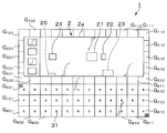
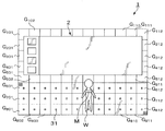
- FIG. 1 is a plan view showing the outline of the overall configuration of a monitoring system having a monitoring device according to the first embodiment.
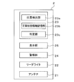
- FIG. 2 is a block diagram showing an outline of a configuration related to a monitoring process of the monitoring device according to the first embodiment.
- the monitoring system 1 of FIG. 1 monitors the floor constituted by the grating G in the clean room by a monitoring device.
- the substrate processing apparatus 2 On the floor to be monitored by the monitoring system 1, for example, the substrate processing apparatus 2 is placed.
- one of the four surfaces, for example, the back surface is located on the grating G 801 to the grating G 812 , and the front surface facing the one surface is on the G 501 to the grating G 512 .
- the substrate processing apparatus 2 On the floor, in the substrate processing apparatus 2, one of the four surfaces, for example, the back surface is located on the grating G 801 to the grating G 812 , and the front surface facing the one surface is on the G 501 to the grating G 512
- An RFID tag 31 as a communication unit that performs communication for detecting the position of the grating G is attached to each of the monitoring target gratings G.
- the RFID tag 31 is attached and attached to the center of the upper surface of the grating G, for example.
- the RFID tag 31 has a storage unit and an antenna (not shown), and the storage unit stores identification information unique to each RFID tag 31, that is, unique to each grating G.
- the RFID tag 31 configured as described above, when receiving a radio wave from an antenna 21 described later included in the substrate processing apparatus 2 that functions as a monitoring device, converts information such as identification information stored in the storage unit into a signal, The signal is transmitted from the antenna of the RFID tag 31.
- the antenna 21 emits a modulated wave (radio wave) to the RFID tag 31 for the purpose of reading the identification information of the RFID tag 31 or receives a signal wave from the RFID tag 31.
- one antenna 21 is attached to a top plate that forms a housing 2a that covers the substrate processing section of the substrate processing apparatus 2.
- a plurality of antennas 21 are provided.
- the grating G to be monitored is only on the front side of the substrate processing apparatus 2, but when the grating G around the entire substrate processing apparatus 2 is to be monitored, the grating G can be arranged in the front, rear, left, and right sides of the housing 2a.
- the reader/writer 22 is provided, for example, adjacent to the antenna 21, and drives the antenna 21.
- control unit 23 the position detection unit 23a, the normal state information storage unit 23b, and the determination unit 23c are mounted by the processing of the CPU according to the instruction of the program for realizing the monitoring processing.
- the normal state information storage unit 23b stores information regarding the position of the grating G in the normal state (hereinafter, may be referred to as "normal state information of the grating G").
- the normal state is a state in which the opening formed by removing the grating G does not exist on the floor of the monitoring target area.
- the determination unit 23c determines the floor monitoring target area based on the detection result of the current position of the grating G by the position detection unit 23a and the normal state information of the grating G stored in the normal state information storage unit 23b. Then, it is determined whether or not there is an opening due to the removal of the grating G.
- the alarm unit 24 and the display unit 25 are output units that output according to the determination result by the determination unit 23c as to whether or not the opening is present.
- the alarm unit 24 issues an alarm with at least one of light and sound.
- the audible alarm may be a form in which the audible alarm is violated or a form in which the warning message is read aloud.
- the alarm unit 24 is provided above the housing 2a of the substrate processing apparatus 2, for example.
- the display unit 25 displays various images, and is composed of, for example, a liquid crystal display, an organic EL display, or the like.
- the display unit 25 displays at least one of an image indicating the presence of the opening and an image indicating the position of the opening.
- the display unit 25 is provided on the front side of the substrate processing apparatus 2, for example.
- the normal state information of the grating G is acquired when the monitoring system 1 is installed.
- the position detection unit 23a controls the reader/writer 22 in a normal state in which neither of the gratings G has been removed and no opening is present.
- the position detection unit 23a changes the posture of the antenna 21 while transmitting radio waves through the antennas 21 for all RFID tags 31 and a signal wave including the above-described identification information that is a response wave to the radio waves. And receive.
- the position detection unit 23a detects the 3D position of each RFID tag 31 in the normal state based on the reception result, thereby detecting the 3D position of each grating G in the normal state.
- the information of these 3D positions is stored in the normal state information storage unit 23b as the normal state information of the grating G.
- the monitoring system 1 When the installation of the monitoring system 1 is completed, the monitoring system 1 operates as follows. That is, the position detection unit 23a controls the reader/writer 22 to change the attitude of the antenna 21 at regular intervals. As a result, the position detection unit 23a transmits the radio wave via the antenna 21 and the above-mentioned identification information, which is a response wave to the radio wave, for all the RFID tags 31 at regular intervals (for example, every one second). Reception of the signal wave containing it is performed. Then, the position detection unit 23a detects the current 3D position of each RFID tag 31 based on the reception result, thereby detecting the current 3D position of each grating G.
- the position detection unit 23a controls the reader/writer 22 to change the attitude of the antenna 21 at regular intervals.
- the position detection unit 23a transmits the radio wave via the antenna 21 and the above-mentioned identification information, which is a response wave to the radio wave, for all the RFID tags 31 at regular intervals (for example, every one second). Reception of
- the determination unit 23c determines whether the current position of each grating G matches the normal position based on the detection result of the position detection unit 23a and the normal state information stored in the normal state information storage unit 23b. Determine whether or not. Then, based on the determination result, the determination unit 23c determines the presence/absence of the opening.
- the position detection unit 23a detects the current 3D position of each grating G at regular intervals, as described above.
- the determination unit 23c causes the current position of each grating G to coincide with the normal state position. To determine. Then, based on the determination result, the determination unit 23c determines whether or not the opening K is closed. For example, when the current positions of all the gratings G match the positions in the normal state, the determination unit 23c determines that the opening K is closed, and the alarm from the alarm unit 24 is stopped.
- the presence or absence of the opening is determined based on the detection result of the current position of the grating G using the communication result with the RFID tag 31 and the normal state information, and the output according to the determination result is performed. There is. Therefore, the worker on site can immediately know that the opening exists. Therefore, even during the work, it is possible to prevent the situation in which the user perceives that the opening exists while the alarm is being issued and performs the work, and accidentally falls from the opening. Further, the surveillance system of the present embodiment does not require expensive equipment such as a surveillance camera, and thus can be constructed at low cost.
- the construction of the monitoring system of the present embodiment can be performed by sequentially attaching the RFID tags 31 on the grating G to be monitored, and wiring work for connecting the RFID tags 31 and the monitoring device is not necessary. Is. Therefore, the monitoring system of the present embodiment can perform the construction work extremely easily and quickly. Of course, it is easy to monitor the existing grating.
- the method of determining the presence or absence of the opening by the determination unit 23c is not limited to the above example.
- the position detection unit 23a determines from the detection result that the grating G in the normal state is arranged in the horizontal plane ( Hereinafter, simply referred to as "array"). Further, the position detection unit 23a stores the information of this array in the normal state information storage unit 23b as the normal state information of the grating G.
- the position detection unit 23a calculates the current array of gratings G from the detection result. Based on the calculation result and the normal state information stored in the normal state information storage unit 23b, the determination unit 23c determines whether the current array of gratings G matches the array of gratings G in the normal state. Based on this determination result, the determination unit 23c determines the presence/absence of the opening. If the arrangement of the grating G in the normal state does not match, it is determined that there is an opening, and the alarm unit 24 issues an alarm, for example. Note that this method can also be used by the determination unit 23c to determine whether or not the opening has been closed.
- the method of determining the presence/absence of an opening by the determination unit 23c may be the following method.
- the position detection unit 23a calculates the interval of the grating G in the normal state from the detection result. .. For example, the distance between each grating G in the normal state and the three other gratings G closest to the grating G is calculated.
- the information on the interval in the normal state is stored in the normal state information storage unit 23b as the normal state information of the grating G.
- the position detection unit 23a calculates the interval of the grating G for each grating G from the detection result. Based on the calculation result and the normal state information stored in the normal state information storage unit 23b, the determination unit 23c determines, for each grating G, whether the current interval between the gratings G matches that in the normal state. Then, based on the determination result, the determination unit 23c determines the presence/absence of the opening. For example, in some of the gratings G, if the spacing of the gratings G does not match the normal state, it is determined that there is an opening, and the alarm unit 24 issues an alarm. Note that this method can also be used by the determination unit 23c to determine whether or not the opening has been closed.
- the determination as to whether or not the opening is closed is based on the determination result as to whether the current position in the height direction of the removed grating G matches the position in the normal height direction. You may go.
- the information on the position in the height direction of each grating G in the normal state is stored in the normal state information storage unit 23b. Further, in the case of this example, when it is determined that the opening is closed, the normal state information stored in the normal state information storage unit 23b may be updated to the information when it is determined that the opening is closed.
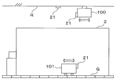
- FIG. 6 is a diagram for explaining another example of the mounting position of the antenna 21.
- the antenna 21 is attached to the housing 2a of the substrate processing apparatus 2.
- the mounting position of the antenna 21 is not limited to this example.
- the antenna 21 may be attached to the ceiling R of a clean room, for example.
- the antenna 21 may be attached to a moving body that moves in the clean room.
- the moving body is, for example, an OHT 100 that moves along a ceiling R or an AGV 101 that runs on a floor formed by a grating G in a clean room.
- the RFID tag 31 which is a passive wireless IC tag is used as a communication unit attached to each grating G to be monitored and performing communication for detecting the position of the grating G.
- the communication unit may be an active wireless IC tag that communicates using a wireless LAN, Bluetooth (registered trademark), ZigBee (registered trademark), or the like.
- a signal wave including the above-mentioned identification information is transmitted from the active wireless IC tag at regular intervals. Therefore, when the RFID tag 31 is used, it is unnecessary to radiate the modulated wave from the antenna 21, which is necessary to send the signal wave from the RFID tag 31.
- the position of the grating G is detected based on the intensity of the signal wave from the wireless IC tag attached to the grating G and the like.
- the method of detecting the position of the grating G is not limited to this method, and may be a method using an optical indoor GPS.
- an optical indoor GPS receiver is used as a communication unit that performs communication for detecting the position of the grating G.
- FIG. 7 is a plan view showing the outline of the overall configuration of the monitoring system 1 when the position of the grating G is detected using the optical indoor GPS.
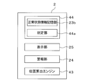
- FIG. 8 is a block diagram showing an outline of a configuration related to a monitoring process of the substrate processing apparatus 2 as a monitoring device when the position of the grating G is detected using the optical indoor GPS.
- a plurality of laser oscillators 41 for optical indoor GPS are used to monitor regions (grating G 601 to grating G 612 , grating G 701 to grating G 712 , It is provided so as to surround the grating G 801 to the grating G 812 .
- an optical sensor 42 as a receiver for an optical indoor GPS is attached to each of the gratings G to be monitored so that the light from the laser oscillator 41 can be received.
- Each laser oscillator 41 emits pulsed laser light at a predetermined timing, for example, under the control of the control unit 44 described later, and each optical sensor 42 A/D-converts the light reception result and outputs it.
- the substrate processing apparatus 2 as the monitoring apparatus of this example has a position calculation engine 43, a control unit 44, and the like.
- the position calculation engine 43 communicates with each optical sensor 42, and detects the position of each grating G by calculating the position of each optical sensor 42 based on the received light intensity at each optical sensor 42.
- the position calculation engine 43 and each optical sensor 42 are wirelessly connected.
- the position detection result of the position calculation engine 43 is used as the normal state information of the grating G, or used for the judgment by the judgment unit 44a described later.
- control unit 44 is a computer including, for example, a CPU and a memory. Further, the control unit 44 is mounted with the determination unit 44a and the like by the processing of the CPU according to the instruction of the program for realizing the monitoring processing.
- the alarm unit 24 and the display unit 25 output according to the determination result by the determination unit 44a.
- the normal state information is stored in the normal state information storage unit 23b of the control unit 23, and the determination unit 23c of the control unit 23 determines whether or not there is an opening.
- the reader/writer 22 is used to write and store the normal state information in each RFID tag 31, and the normal state information is acquired together with the identification information from each RFID tag 31 at the time of monitoring. May be performed by the reader/writer 22. As a result, the load on the control unit 23, which is the host controller, can be reduced.
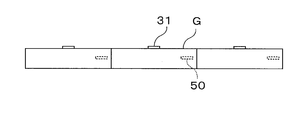
- FIG. 9 is a diagram for explaining the monitoring device according to the second embodiment, and shows the side surface of the grating G that constitutes the floor of the clean room.
- an active type wireless IC tag including an acceleration sensor and a gyro sensor as an operation detection unit is incorporated. 50 is attached.
- the active wireless IC tag 50 radiates a signal wave including a motion detection result for the grating G in the acceleration sensor and the gyro sensor at regular intervals, and the signal wave is received via the antenna of the monitoring device.
- the determination unit that is included in the monitoring device and determines whether or not there is an opening in the floor makes the above determination based on the following (A) to (C).
- the opening is present regardless of the result of motion detection of the grating G by the acceleration sensor and the gyro sensor. Further, when the motion for a part of the grating G is detected by the acceleration sensor and the gyro sensor, it is determined that the opening is present regardless of whether or not the position of the grating G matches the position in the normal state.
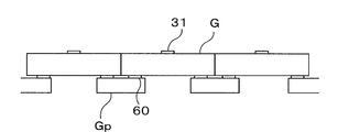
- FIG. 10 is a diagram illustrating another example of the motion detector.
- an active wireless IC tag 60 having a built-in weight sensor (pressure sensor) as an operation detection unit is attached to each mounting portion Gp of the grating G.
- FIG. 11 is a diagram for explaining the monitoring device according to the third embodiment.
- the substrate processing apparatus 2 also serves as the monitoring device.
- the portable terminal device M of the worker W functions as a monitoring device.
- the mobile terminal device M includes the antenna 21, the reader/writer 22, the control unit 23, the alarm unit 24, and the display unit 25 described with reference to FIG. Then, when it is determined that the opening is present based on the result received via the antenna 21 of the mobile terminal device M, for example, a warning is given by a sound from the alarm unit 24 or the position of the opening by the display unit 25 is indicated. The image is displayed.
- a vibrating vibrating unit may be provided in the mobile terminal device M, and when it is determined that the opening is present, the worker W may be warned by the vibration. Further, in the present embodiment, the functions related to the monitoring processing of the control unit 23, the alarm unit 24, and the display unit 25 may be provided in the substrate processing apparatus 2.
- the technology according to the present disclosure can be applied to a floor in a space other than a clean room, and can also be applied to a floor configured by floor members other than grating.
- a monitoring device for monitoring a floor configured by grating in a clean room Each grating is equipped with a communication unit that performs communication for detecting the position of the grating.
- the monitoring device is The presence or absence of the opening based on the detection result of the current position of the grating using the communication result with the communication unit and the information on the position of the grating in the normal state where the opening caused by the removal of the grating does not exist.
- the surveillance system according to (1) above can be constructed at low cost. Furthermore, the monitoring system according to (1) above can be constructed very easily and quickly.
- a motion detector that detects a motion for the grating is provided, The determination unit determines the presence or absence of the opening based on the detection result of the current grating position, information about the position of the grating in the normal state, and the detection result of the operation detecting unit.
- the monitoring device according to (1) above. According to the above (6), the safety can be further enhanced.
- the output unit is a display unit that displays at least one of an image indicating the presence of the opening and an image indicating the position of the opening when the opening is present,
- the monitoring device according to any one of (1) to (11).
- a monitoring method for monitoring a floor configured by grating in a clean room Each grating is equipped with a communication unit that performs communication for detecting the position of the grating.
- the monitoring method is A step of detecting the current position of the grating based on the communication result with the communication unit; Based on the result of the detection and the information about the position of the grating in a normal state in which the opening is not formed when the grating is removed, a step of determining the presence or absence of the opening, An output step of outputting according to the determination result of the presence or absence of the opening, the monitoring method.
- a substrate processing apparatus for processing a substrate comprising: The substrate processing apparatus is to be placed on a floor composed of grating in a clean room, Each grating is equipped with a communication unit that performs communication for detecting the position of the grating.
- the substrate processing apparatus is The presence or absence of the opening based on the detection result of the current position of the grating using the communication result with the communication unit and the information on the position of the grating in the normal state where the opening caused by the removal of the grating does not exist.
- a determination unit for determining comprising: an output unit that outputs according to a determination result of the presence or absence of the opening in the determination unit.
Abstract
Provided is a monitoring device which monitors a floor comprising gratings within a clean room. Communication units are attached to each of the gratings and carry out communications for detecting the positions of the gratings. The monitoring device comprises: a determination unit which, on the basis of the result of the detection of the present positions of the gratings using the result of the communications with the communication units and of information relating to the positions of the gratings in a normal state where no aperture parts that are the result of the gratings being removed are present, carries out a determination of the presence of the aperture parts; and an output unit which carries out an output according to the result of the determination of the presence of the aperture parts by the determination unit.
Description
本開示は、監視装置、監視方法及び基板処理装置に関する。
The present disclosure relates to a monitoring device, a monitoring method, and a substrate processing device.
特許文献1には、床部に取り外し可能な床面が配置されたクリーンルームの内部を監視するためのクリーンルームの監視装置が開示されている。このクリーンルームの監視装置は、作業員が通行可能な通路の上記取り外し可能な床面を撮像する監視カメラを備えている。監視カメラで得られた画像信号から、上記取り外し可能な床面が取り外された開口部の有無が検出され、開口部が有る場合は当該開口部に接近する作業員の有無が監視カメラの画像信号から検出される。そしてこのクリーンルームの監視装置は、作業員が検出された際に警報信号を出力する監視部と、監視部から警報信号を受け、警報を発する警報発生手段とを備えている。
Patent Document 1 discloses a clean room monitoring device for monitoring the inside of a clean room in which a removable floor surface is arranged on the floor. This monitoring device for a clean room is equipped with a monitoring camera for taking an image of the removable floor surface of a passage through which a worker can pass. The presence or absence of the opening from which the removable floor surface has been removed is detected from the image signal obtained by the surveillance camera, and if there is an opening, the presence or absence of an operator approaching the opening is the image signal of the surveillance camera. Detected from. The clean room monitoring device includes a monitoring unit that outputs an alarm signal when a worker is detected, and an alarm generation unit that receives an alarm signal from the monitoring unit and issues an alarm.
本開示にかかる技術は、クリーンルーム内のグレーチングが外されて開口した際に作業員の安全性を向上させる。
The technology according to the present disclosure improves the safety of workers when the grating in the clean room is removed and opened.
本開示の一態様は、クリーンルーム内のグレーチングにより構成される床を監視する監視装置であって、グレーチングのそれぞれには、当該グレーチングの位置を検出するための通信を行う通信部が取り付けられており、当該監視装置は、前記通信部との通信結果を用いた現在のグレーチングの位置の検出結果と、グレーチングが取り外されて生じる開口部が存在しない正常状態のグレーチングの位置に関する情報と、に基づいて、前記開口部の有無の判定を行う判定部と、前記判定部での前記開口部の有無の判定結果に応じて出力を行う出力部と、を有する。
One aspect of the present disclosure is a monitoring device that monitors a floor configured by grating in a clean room, and a communication unit that performs communication for detecting the position of the grating is attached to each grating. , The monitoring device, based on the detection result of the current position of the grating using the communication result with the communication unit, and information about the position of the grating in a normal state in which there is no opening caused by removing the grating, A determination unit that determines the presence or absence of the opening, and an output unit that outputs according to the determination result of the presence or absence of the opening in the determination unit.
本開示によれば、クリーンルーム内のグレーチングが外されて開口した際に作業員の安全性を向上させることができる。
According to the present disclosure, it is possible to improve the safety of the worker when the grating in the clean room is removed and opened.
従来から、例えば半導体装置を製造するための半導体製造ラインでは、多数の半導体製造装置が、清浄雰囲気とされたクリーンルーム内に配設されている。このようなクリーンルームでは、床部分には多数の格子状の通気部を有するグレーチングが配設されている。また、グレーチングの下部空間には配管や各種電気機器、ポンプ類、薬液タンク等が収容されている。たとえばこれら配管や各種電気機器、ポンプ類等の設置や保守、故障時には、作業員がグレーチングの下部空間に降りて作業をする必要があるため、グレーチングは取り外し自在となっている。
Conventionally, for example, in a semiconductor manufacturing line for manufacturing semiconductor devices, a large number of semiconductor manufacturing devices are arranged in a clean room in a clean atmosphere. In such a clean room, a grating having a large number of lattice-like ventilation portions is arranged on the floor portion. In the space below the grating, pipes, various electric devices, pumps, chemical tanks, etc. are housed. For example, when the installation, maintenance, or breakdown of these pipes, various electric devices, pumps, and the like occurs, it is necessary for the worker to descend to the lower space of the grating to perform work, and thus the grating is removable.
このようにグレーチングを取り外した状態で、グレーチング下部の空間に作業員が入り作業を行えるようになっている。しかしながらグレーチングを取り外した場合、多数のグレーチングによって構成されているクリーンルームの床面に開口部が形成されるため、作業員がこの開口部から下部空間へと落下する危険性がある。とりわけグレーチング上で他の作業を行なっている作業員にとっては、開口部が形成されていることを知らずに作業をしていることがあり、従来から作業員に注意を促すことが行われている。
In this way, with the grating removed, workers can enter the space below the grating and work. However, when the grating is removed, an opening is formed on the floor surface of the clean room constituted by a large number of gratings, so that there is a risk that a worker falls from the opening to the lower space. Especially for workers who are doing other work on the grating, they may be working without knowing that the opening is formed, and it has been conventionally warned to the worker. ..
特許文献1に記載の技術は、グレーチングを撮像する監視カメラと、当該監視カメラで得られた画像信号に基づいて、グレーチングが取り外された開口部の有無を検出し、作業員がいる場合には、警報信号を出力して警報発生手段から警報を発するようにしている。
The technique described in Patent Document 1 detects the presence or absence of an opening from which the grating is removed based on a surveillance camera that captures an image of the grating, and an image signal obtained by the surveillance camera, and when there is a worker. An alarm signal is output and an alarm is issued from an alarm generating means.
かかる技術によって、作業員の安全性は向上したが、監視カメラの設置など高価な装置の設置が必要である。そこでより低コストで構築可能な監視システムを本開示は提供する。以下に実施形態にかかる監視装置を説明する。なお、本明細書及び図面において、実質的に同一の機能構成を有する要素については、同一の符号を付することにより重複説明を省略する。
The safety of workers has been improved by such technology, but expensive equipment such as surveillance cameras must be installed. Therefore, the present disclosure provides a monitoring system that can be constructed at a lower cost. The monitoring device according to the embodiment will be described below. In the present specification and the drawings, elements having substantially the same functional configuration are designated by the same reference numerals, and duplicate description will be omitted.
(第1実施形態)
図1は、第1実施形態にかかる監視装置を有する監視システムの全体構成の概略を示す平面図である。図2は、第1実施形態にかかる監視装置の監視処理にかかる構成の概略を示すブロック図である。
図1の監視システム1は、クリーンルーム内のグレーチングGで構成された床を監視装置によって監視するものである。
監視システム1の監視対象の床には、例えば、基板処理装置2が載置される。床の上において、基板処理装置2は、その四面の内のうちの一面、例えば背面がグレーチングG801~グレーチングG812上に位置し、当該一面と対向する正面がG501~グレーチングG512上に位置する。また、基板処理装置2の一側面は、グレーチングG101、G201、G301、G401、G501上に位置し、他側面はグレーチングG112、G212、G312、G412、G512上に位置する。 (First embodiment)
FIG. 1 is a plan view showing the outline of the overall configuration of a monitoring system having a monitoring device according to the first embodiment. FIG. 2 is a block diagram showing an outline of a configuration related to a monitoring process of the monitoring device according to the first embodiment.
Themonitoring system 1 of FIG. 1 monitors the floor constituted by the grating G in the clean room by a monitoring device.
On the floor to be monitored by themonitoring system 1, for example, the substrate processing apparatus 2 is placed. On the floor, in the substrate processing apparatus 2, one of the four surfaces, for example, the back surface is located on the grating G 801 to the grating G 812 , and the front surface facing the one surface is on the G 501 to the grating G 512 . To position. One side surface of the substrate processing apparatus 2 is located on the gratings G 101 , G 201 , G 301 , G 401 , and G 501 , and the other side surface is on the gratings G 112 , G 212 , G 312 , G 412 , and G 512 . Located in.
図1は、第1実施形態にかかる監視装置を有する監視システムの全体構成の概略を示す平面図である。図2は、第1実施形態にかかる監視装置の監視処理にかかる構成の概略を示すブロック図である。
図1の監視システム1は、クリーンルーム内のグレーチングGで構成された床を監視装置によって監視するものである。
監視システム1の監視対象の床には、例えば、基板処理装置2が載置される。床の上において、基板処理装置2は、その四面の内のうちの一面、例えば背面がグレーチングG801~グレーチングG812上に位置し、当該一面と対向する正面がG501~グレーチングG512上に位置する。また、基板処理装置2の一側面は、グレーチングG101、G201、G301、G401、G501上に位置し、他側面はグレーチングG112、G212、G312、G412、G512上に位置する。 (First embodiment)
FIG. 1 is a plan view showing the outline of the overall configuration of a monitoring system having a monitoring device according to the first embodiment. FIG. 2 is a block diagram showing an outline of a configuration related to a monitoring process of the monitoring device according to the first embodiment.
The
On the floor to be monitored by the
監視システム1は、上述のように位置する基板処理装置2の周囲の床を監視し、具体的には、基板処理装置2の周囲のグレーチングGのうち、基板処理装置2が上方に位置しておらず開口部を形成し得るグレーチングGを監視している。なお、以下の説明では、基板処理装置2の正面側のグレーチングGのみが開口部を形成し得るものとする。つまり、以下の説明では、監視システム1は、基板処理装置2の正面側のグレーチングG601~グレーチングG612、グレーチングG701~グレーチングG712、グレーチングG801~グレーチングG812を監視する。
The monitoring system 1 monitors the floor around the substrate processing apparatus 2 located as described above. Specifically, in the grating G around the substrate processing apparatus 2, the substrate processing apparatus 2 is located above. However, the grating G that can form the opening is monitored. In the following description, it is assumed that only the grating G on the front side of the substrate processing apparatus 2 can form the opening. That is, in the following description, the monitoring system 1 monitors the grating G 601 to the grating G 612 , the grating G 701 to the grating G 712 , and the grating G 801 to the grating G 812 on the front side of the substrate processing apparatus 2.
監視対象のグレーチングGにはそれぞれ、当該グレーチングGの位置を検出するための通信を行う通信部としてのRFIDタグ31が取り付けられている。RFIDタグ31は、例えばグレーチングGの上面中央に貼り付けられて取り付けられる。RFIDタグ31は、不図示の記憶部とアンテナを有し、上記記憶部には、RFIDタグ31毎に固有の、すなわち、グレーチングG毎に固有の識別情報が記憶されている。このように構成されるRFIDタグ31は、監視装置として機能する基板処理装置2が有する後述のアンテナ21から電波を受信すると、上記記憶部に記憶されている識別情報等の情報を信号化して、当該RFIDタグ31が有するアンテナからその信号を発信する。
An RFID tag 31 as a communication unit that performs communication for detecting the position of the grating G is attached to each of the monitoring target gratings G. The RFID tag 31 is attached and attached to the center of the upper surface of the grating G, for example. The RFID tag 31 has a storage unit and an antenna (not shown), and the storage unit stores identification information unique to each RFID tag 31, that is, unique to each grating G. The RFID tag 31 configured as described above, when receiving a radio wave from an antenna 21 described later included in the substrate processing apparatus 2 that functions as a monitoring device, converts information such as identification information stored in the storage unit into a signal, The signal is transmitted from the antenna of the RFID tag 31.
監視システム1は、このRFIDタグ31と、監視装置としての基板処理装置2を有する。
監視装置としての基板処理装置2は、半導体ウェハ等の基板に対しレジスト液塗布処理等の各種処理を行う基板処理部を複数有し、さらに、図2に示すように、受信部としてのアンテナ21と、リーダライタ22と、制御部23と、警報部24と、表示部25とを有する。 Themonitoring system 1 has the RFID tag 31 and the substrate processing apparatus 2 as a monitoring device.
Thesubstrate processing apparatus 2 as a monitoring device has a plurality of substrate processing units for performing various processes such as resist solution coating process on a substrate such as a semiconductor wafer, and further, as shown in FIG. 2, an antenna 21 as a receiving unit. The reader/writer 22, the control unit 23, the alarm unit 24, and the display unit 25 are included.
監視装置としての基板処理装置2は、半導体ウェハ等の基板に対しレジスト液塗布処理等の各種処理を行う基板処理部を複数有し、さらに、図2に示すように、受信部としてのアンテナ21と、リーダライタ22と、制御部23と、警報部24と、表示部25とを有する。 The
The
アンテナ21は、RFIDタグ31の識別情報を読み取ること等を目的として変調波(電波)をRFIDタグ31へ放射したり、RFIDタグ31からの信号波を受信したりする。このアンテナ21は、例えば基板処理装置2の基板処理部を覆う筐体2aを構成する天板に1つ取り付けられている。なお、1つのアンテナ21による電波の放射範囲及び受信範囲では監視対象の領域全体を覆うことができないときは、アンテナ21は複数設けられる。本例では、監視対象のグレーチングGが基板処理装置2の正面側のみであるが、基板処理装置2の周囲全体のグレーチングGを監視対象とする場合は、上記筐体2aを構成する前後左右の4つの側壁それぞれにアンテナ21を取り付けても良い。
また、アンテナ21は、各RFIDタグ31の3次元位置すなわち各グレーチングGの3次元位置が特定できるように、例えば、当該アンテナ21の姿勢を変化可能に構成されている。 Theantenna 21 emits a modulated wave (radio wave) to the RFID tag 31 for the purpose of reading the identification information of the RFID tag 31 or receives a signal wave from the RFID tag 31. For example, one antenna 21 is attached to a top plate that forms a housing 2a that covers the substrate processing section of the substrate processing apparatus 2. In addition, when the entire range of the monitoring target cannot be covered by the radiation range and the reception range of the radio wave by one antenna 21, a plurality of antennas 21 are provided. In this example, the grating G to be monitored is only on the front side of the substrate processing apparatus 2, but when the grating G around the entire substrate processing apparatus 2 is to be monitored, the grating G can be arranged in the front, rear, left, and right sides of the housing 2a. The antenna 21 may be attached to each of the four side walls.
Further, theantenna 21 is configured, for example, so that the posture of the antenna 21 can be changed so that the three-dimensional position of each RFID tag 31, that is, the three-dimensional position of each grating G can be specified.
また、アンテナ21は、各RFIDタグ31の3次元位置すなわち各グレーチングGの3次元位置が特定できるように、例えば、当該アンテナ21の姿勢を変化可能に構成されている。 The
Further, the
リーダライタ22は、例えばアンテナ21に隣接して設けられており、アンテナ21を駆動するものである。
The reader/writer 22 is provided, for example, adjacent to the antenna 21, and drives the antenna 21.
制御部23は、例えばCPUやメモリ等を備えたコンピュータであり、プログラム格納部(図示せず)を有している。プログラム格納部には、基板処理装置2における処理を制御するプログラムが格納されている。また、後述の監視処理を実現させるためのプログラムも格納されている。なお、上記プログラムは、コンピュータに読み取り可能な記憶媒体に記録されていたものであって、当該記憶媒体から制御部23にインストールされたものであってもよい。
また、制御部23は、例えば基板処理装置2の筐体2aの内部に設けられる。 Thecontrol unit 23 is a computer including, for example, a CPU and a memory, and has a program storage unit (not shown). The program storage unit stores a program for controlling the processing in the substrate processing apparatus 2. In addition, a program for realizing a monitoring process described later is also stored. The program may be recorded in a computer-readable storage medium and installed in the control unit 23 from the storage medium.
Thecontrol unit 23 is provided inside the housing 2a of the substrate processing apparatus 2, for example.
また、制御部23は、例えば基板処理装置2の筐体2aの内部に設けられる。 The
The
さらに、制御部23には、監視処理を実現させるためのプログラムの指示に従ったCPUの処理により、位置検出部23a、正常状態情報記憶部23b及び判定部23cが実装される。
Further, in the control unit 23, the position detection unit 23a, the normal state information storage unit 23b, and the determination unit 23c are mounted by the processing of the CPU according to the instruction of the program for realizing the monitoring processing.
位置検出部23aは、RFIDタグ31との通信結果に基づいて、現在のグレーチングの位置の検出を行う。具体的には、位置検出部23aは、リーダライタ22を制御して、アンテナ21の姿勢を変化させながら当該アンテナ21から電波を送出させる。また、その電波に対する応答波として、各RFIDタグ31が、識別情報を含む信号波を送出するので、位置検出部23aは、アンテナ21を介して上述の信号波をRFIDタグ31毎に複数回受信させる。そして、位置検出部23aは、それぞれのRFIDタグ31について、つまりは、監視対象のグレーチングGそれぞれについて、アンテナ21の姿勢変化の情報と、姿勢に応じた応答波の信号強度とに基づいて、現在の3D位置を検出する。
The position detection unit 23a detects the current position of grating based on the communication result with the RFID tag 31. Specifically, the position detection unit 23a controls the reader/writer 22 to transmit a radio wave from the antenna 21 while changing the attitude of the antenna 21. Further, since each RFID tag 31 sends out a signal wave including identification information as a response wave to the radio wave, the position detection unit 23a receives the above-mentioned signal wave a plurality of times for each RFID tag 31 via the antenna 21. Let Then, the position detection unit 23a, for each RFID tag 31, that is, for each of the monitoring target grating G, based on the information of the attitude change of the antenna 21 and the signal strength of the response wave according to the attitude, The 3D position of is detected.
正常状態情報記憶部23bは、正常状態のグレーチングGの位置に関する情報(以下、「グレーチングGの正常状態情報」ということがある。)を記憶する。正常状態とは、グレーチングGが取り外されて生じる開口部が監視対象領域の床に存在しない状態である。
The normal state information storage unit 23b stores information regarding the position of the grating G in the normal state (hereinafter, may be referred to as "normal state information of the grating G"). The normal state is a state in which the opening formed by removing the grating G does not exist on the floor of the monitoring target area.
判定部23cは、位置検出部23aによる、現在のグレーチングGの位置の検出結果と、正常状態情報記憶部23bに記憶されている、グレーチングGの正常状態情報とに基づいて、床の監視対象領域に、グレーチングGが取り外されたことによる開口部が存在するか判定する。
The determination unit 23c determines the floor monitoring target area based on the detection result of the current position of the grating G by the position detection unit 23a and the normal state information of the grating G stored in the normal state information storage unit 23b. Then, it is determined whether or not there is an opening due to the removal of the grating G.
警報部24及び表示部25は、判定部23cによる上記開口部が存在するかの否かの判定結果に応じて出力を行う出力部である。
警報部24は、判定部23cにより上記開口部が存在すると判定された場合、光及び音の少なくともいずれか一方により警報を発する。音による警報は、警報音を反する形態であっても、音声によって警告メッセージを読み上げる形態であってもよい。この警報部24は例えば基板処理装置2の筐体2aの上方に設けられる。
表示部25は、各種画像を表示するものであって、例えば、液晶ディスプレイ、有機ELディスプレイ等から構成されている。表示部25は、判定部23cにより上記開口部が存在すると判定された場合、上記開口部が存在することを示す画像及び上記開口部の位置を示す画像の少なくともいずれか一方を表示する。この表示部25は例えば基板処理装置2の正面側に設けられる。 Thealarm unit 24 and the display unit 25 are output units that output according to the determination result by the determination unit 23c as to whether or not the opening is present.
When thedetermination unit 23c determines that the opening is present, the alarm unit 24 issues an alarm with at least one of light and sound. The audible alarm may be a form in which the audible alarm is violated or a form in which the warning message is read aloud. The alarm unit 24 is provided above the housing 2a of the substrate processing apparatus 2, for example.
Thedisplay unit 25 displays various images, and is composed of, for example, a liquid crystal display, an organic EL display, or the like. When the determination unit 23c determines that the opening is present, the display unit 25 displays at least one of an image indicating the presence of the opening and an image indicating the position of the opening. The display unit 25 is provided on the front side of the substrate processing apparatus 2, for example.
警報部24は、判定部23cにより上記開口部が存在すると判定された場合、光及び音の少なくともいずれか一方により警報を発する。音による警報は、警報音を反する形態であっても、音声によって警告メッセージを読み上げる形態であってもよい。この警報部24は例えば基板処理装置2の筐体2aの上方に設けられる。
表示部25は、各種画像を表示するものであって、例えば、液晶ディスプレイ、有機ELディスプレイ等から構成されている。表示部25は、判定部23cにより上記開口部が存在すると判定された場合、上記開口部が存在することを示す画像及び上記開口部の位置を示す画像の少なくともいずれか一方を表示する。この表示部25は例えば基板処理装置2の正面側に設けられる。 The
When the
The
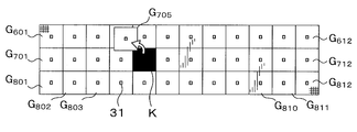
次に、監視システム1による監視処理の一例について図3を用いて説明する。
まず、監視システム1の設置時等に、グレーチングGの正常状態情報が取得される。具体的には、位置検出部23aが、いずれのグレーチングGも取り外されておらず開口部が存在しない正常状態で、リーダライタ22を制御する。これにより、位置検出部23aは、アンテナ21の姿勢を変化させながら、全RFIDタグ31について、アンテナ21を介した電波の送信と、当該電波に対する応答波である、前述の識別情報を含む信号波の受信と、を行う。そして、位置検出部23aが、受信結果に基づいて、正常状態での各RFIDタグ31の3D位置を検出することで、正常状態での各グレーチングGの3D位置を検出する。これら3D位置の情報は、グレーチングGの正常状態情報として正常状態情報記憶部23bに記憶される。 Next, an example of the monitoring process by themonitoring system 1 will be described with reference to FIG.
First, the normal state information of the grating G is acquired when themonitoring system 1 is installed. Specifically, the position detection unit 23a controls the reader/writer 22 in a normal state in which neither of the gratings G has been removed and no opening is present. As a result, the position detection unit 23a changes the posture of the antenna 21 while transmitting radio waves through the antennas 21 for all RFID tags 31 and a signal wave including the above-described identification information that is a response wave to the radio waves. And receive. Then, the position detection unit 23a detects the 3D position of each RFID tag 31 in the normal state based on the reception result, thereby detecting the 3D position of each grating G in the normal state. The information of these 3D positions is stored in the normal state information storage unit 23b as the normal state information of the grating G.
まず、監視システム1の設置時等に、グレーチングGの正常状態情報が取得される。具体的には、位置検出部23aが、いずれのグレーチングGも取り外されておらず開口部が存在しない正常状態で、リーダライタ22を制御する。これにより、位置検出部23aは、アンテナ21の姿勢を変化させながら、全RFIDタグ31について、アンテナ21を介した電波の送信と、当該電波に対する応答波である、前述の識別情報を含む信号波の受信と、を行う。そして、位置検出部23aが、受信結果に基づいて、正常状態での各RFIDタグ31の3D位置を検出することで、正常状態での各グレーチングGの3D位置を検出する。これら3D位置の情報は、グレーチングGの正常状態情報として正常状態情報記憶部23bに記憶される。 Next, an example of the monitoring process by the
First, the normal state information of the grating G is acquired when the
監視システム1の設置が完了すると、監視システム1は以下のように動作する。すなわち、位置検出部23aが、一定間隔毎に、リーダライタ22を制御して、アンテナ21の姿勢を変化させる。これにより、位置検出部23aが、一定間隔毎(例えば1秒毎)に、全てのRFIDタグ31について、アンテナ21を介した電波の送信と、当該電波に対する応答波である、前述の識別情報を含む信号波の受信と、を行う。次いで、位置検出部23aが、受信結果に基づいて、現在の各RFIDタグ31の3D位置を検出することで、現在の各グレーチングGの3D位置を検出する。そして、判定部23cが、位置検出部23aでの検出結果と、正常状態情報記憶部23bに記憶の正常状態情報とに基づいて、現在の各グレーチングGの位置が正常状態の位置に一致するか否か判定する。そして、その判定結果に基づいて、判定部23cが、開口部の有無の判定を行う。
When the installation of the monitoring system 1 is completed, the monitoring system 1 operates as follows. That is, the position detection unit 23a controls the reader/writer 22 to change the attitude of the antenna 21 at regular intervals. As a result, the position detection unit 23a transmits the radio wave via the antenna 21 and the above-mentioned identification information, which is a response wave to the radio wave, for all the RFID tags 31 at regular intervals (for example, every one second). Reception of the signal wave containing it is performed. Then, the position detection unit 23a detects the current 3D position of each RFID tag 31 based on the reception result, thereby detecting the current 3D position of each grating G. Then, the determination unit 23c determines whether the current position of each grating G matches the normal position based on the detection result of the position detection unit 23a and the normal state information stored in the normal state information storage unit 23b. Determine whether or not. Then, based on the determination result, the determination unit 23c determines the presence/absence of the opening.
図3に示すように、例えば、一部のグレーチングGの現在の水平面内における位置が正常状態から変化している場合(図の例ではグレーチングG705の水平面内における位置が正常状態から変化している)は、判定部23cは開口部Kが形成されていると判定する。
開口部Kが形成されていると判定した場合、警報部24が例えば光による警報を発する。 As shown in FIG. 3, for example, when the positions of some of the gratings G in the current horizontal plane have changed from the normal state (in the example of the figure, the positions of the grating G 705 in the horizontal plane have changed from the normal state). ), thedetermination unit 23c determines that the opening K is formed.
When it is determined that the opening K is formed, thealarm unit 24 issues an alarm by light, for example.
開口部Kが形成されていると判定した場合、警報部24が例えば光による警報を発する。 As shown in FIG. 3, for example, when the positions of some of the gratings G in the current horizontal plane have changed from the normal state (in the example of the figure, the positions of the grating G 705 in the horizontal plane have changed from the normal state). ), the
When it is determined that the opening K is formed, the
警報を発している間も、位置検出部23aが、上述と同様に、一定間隔毎に、現在の各グレーチングGの3D位置を検出する。また、この位置検出部23aでの検出結果と、正常状態情報記憶部23bに記憶の正常状態情報とに基づいて、判定部23cが、現在の各グレーチングGの位置が正常状態の位置に一致するか判定する。そして、その判定結果に基づいて、判定部23cが、開口部Kが閉じられたか否かを判定する。例えば、全てのグレーチングGの現在の位置が正常状態の位置に一致する場合、判定部23cは、開口部Kが閉じられたと判定し、警報部24からの警報が停止される。
While the alarm is being issued, the position detection unit 23a detects the current 3D position of each grating G at regular intervals, as described above. In addition, based on the detection result of the position detection unit 23a and the normal state information stored in the normal state information storage unit 23b, the determination unit 23c causes the current position of each grating G to coincide with the normal state position. To determine. Then, based on the determination result, the determination unit 23c determines whether or not the opening K is closed. For example, when the current positions of all the gratings G match the positions in the normal state, the determination unit 23c determines that the opening K is closed, and the alarm from the alarm unit 24 is stopped.
本実施形態では、RFIDタグ31との通信結果を用いた現在のグレーチングGの位置の検出結果と正常状態情報とに基づいて、開口部の有無を判定し、判定結果に応じた出力を行っている。したがって、現場にいる作業員は、開口部が存在することを直ちに知ることができる。それゆえ作業中であっても、警報が発せられている間は開口部が存在すると知覚して、作業を行うことになり、誤って開口部から落ちてしまうという事態を防止できる。
また、本実施形態の監視システムは、監視カメラ等の高価な装置が不要であるため、低コストで構築することができる。
さらに、本実施形態の監視システムの構築は、監視対象とするグレーチングG上に、RFIDタグ31を順次貼り付けることで行うことができ、RFIDタグ31と監視装置とを接続する配線作業等も不要である。そのため、本実施形態の監視システムは、構築作業が極めて簡単、かつ迅速に行うことができる。もちろん既存のグレーチングを監視対象とするのも容易である。 In the present embodiment, the presence or absence of the opening is determined based on the detection result of the current position of the grating G using the communication result with theRFID tag 31 and the normal state information, and the output according to the determination result is performed. There is. Therefore, the worker on site can immediately know that the opening exists. Therefore, even during the work, it is possible to prevent the situation in which the user perceives that the opening exists while the alarm is being issued and performs the work, and accidentally falls from the opening.
Further, the surveillance system of the present embodiment does not require expensive equipment such as a surveillance camera, and thus can be constructed at low cost.
Furthermore, the construction of the monitoring system of the present embodiment can be performed by sequentially attaching the RFID tags 31 on the grating G to be monitored, and wiring work for connecting the RFID tags 31 and the monitoring device is not necessary. Is. Therefore, the monitoring system of the present embodiment can perform the construction work extremely easily and quickly. Of course, it is easy to monitor the existing grating.
また、本実施形態の監視システムは、監視カメラ等の高価な装置が不要であるため、低コストで構築することができる。
さらに、本実施形態の監視システムの構築は、監視対象とするグレーチングG上に、RFIDタグ31を順次貼り付けることで行うことができ、RFIDタグ31と監視装置とを接続する配線作業等も不要である。そのため、本実施形態の監視システムは、構築作業が極めて簡単、かつ迅速に行うことができる。もちろん既存のグレーチングを監視対象とするのも容易である。 In the present embodiment, the presence or absence of the opening is determined based on the detection result of the current position of the grating G using the communication result with the
Further, the surveillance system of the present embodiment does not require expensive equipment such as a surveillance camera, and thus can be constructed at low cost.
Furthermore, the construction of the monitoring system of the present embodiment can be performed by sequentially attaching the RFID tags 31 on the grating G to be monitored, and wiring work for connecting the RFID tags 31 and the monitoring device is not necessary. Is. Therefore, the monitoring system of the present embodiment can perform the construction work extremely easily and quickly. Of course, it is easy to monitor the existing grating.
なお、上述の例では、現在の各グレーチングGの位置が正常状態の位置に一致するか否かの判定は、水平面内における位置に基づいて行ったが、高さ方向にかかる位置に基づいて行っても良いし、水平面内における位置及び高さ方向にかかる位置の両方に基づいて行ってもよい。
In the above example, whether or not the current position of each grating G matches the position in the normal state was determined based on the position in the horizontal plane, but based on the position applied in the height direction. Alternatively, it may be performed based on both the position in the horizontal plane and the position in the height direction.
(開口部の有無の判定方法の他の例1)
判定部23cによる開口部の有無の判定方法は上述の例に限られない。
例えば、正常状態情報を取得する際に、正常状態での各グレーチングGの3D位置を検出したときに、当該検出結果から、位置検出部23aが、正常状態でのグレーチングGの水平面内における配列(以下、単に「配列」という。)を算出するようにする。また、位置検出部23aが、この配列の情報を、グレーチングGの正常状態情報として正常状態情報記憶部23bに記憶させる。そして、監視の際は、一定間隔毎に現在の各グレーチングGの3D位置が検出されたときに、当該検出結果から、位置検出部23aが、現在のグレーチングGの配列を算出する。この算出結果と正常状態情報記憶部23bに記憶の正常状態情報に基づいて、判定部23cが、現在のグレーチングGの配列が、正常状態でのグレーチングGの配列と一致するか判定する。この判定結果に基づいて、判定部23cが、開口部の有無の判定を行う。正常状態でのグレーチングGの配列に一致しない場合は、開口部があると判定され、例えば警報部24から警報が発せられる。
なお、判定部23cによる、開口部が閉じられたか否かの判定にも、この方法を用いることができる。 (Other example 1 of determination method of presence/absence of opening)
The method of determining the presence or absence of the opening by thedetermination unit 23c is not limited to the above example.
For example, when acquiring the normal state information, when the 3D position of each grating G in the normal state is detected, theposition detection unit 23a determines from the detection result that the grating G in the normal state is arranged in the horizontal plane ( Hereinafter, simply referred to as "array"). Further, the position detection unit 23a stores the information of this array in the normal state information storage unit 23b as the normal state information of the grating G. Then, during monitoring, when the current 3D position of each grating G is detected at regular intervals, the position detection unit 23a calculates the current array of gratings G from the detection result. Based on the calculation result and the normal state information stored in the normal state information storage unit 23b, the determination unit 23c determines whether the current array of gratings G matches the array of gratings G in the normal state. Based on this determination result, the determination unit 23c determines the presence/absence of the opening. If the arrangement of the grating G in the normal state does not match, it is determined that there is an opening, and the alarm unit 24 issues an alarm, for example.
Note that this method can also be used by thedetermination unit 23c to determine whether or not the opening has been closed.
判定部23cによる開口部の有無の判定方法は上述の例に限られない。
例えば、正常状態情報を取得する際に、正常状態での各グレーチングGの3D位置を検出したときに、当該検出結果から、位置検出部23aが、正常状態でのグレーチングGの水平面内における配列(以下、単に「配列」という。)を算出するようにする。また、位置検出部23aが、この配列の情報を、グレーチングGの正常状態情報として正常状態情報記憶部23bに記憶させる。そして、監視の際は、一定間隔毎に現在の各グレーチングGの3D位置が検出されたときに、当該検出結果から、位置検出部23aが、現在のグレーチングGの配列を算出する。この算出結果と正常状態情報記憶部23bに記憶の正常状態情報に基づいて、判定部23cが、現在のグレーチングGの配列が、正常状態でのグレーチングGの配列と一致するか判定する。この判定結果に基づいて、判定部23cが、開口部の有無の判定を行う。正常状態でのグレーチングGの配列に一致しない場合は、開口部があると判定され、例えば警報部24から警報が発せられる。
なお、判定部23cによる、開口部が閉じられたか否かの判定にも、この方法を用いることができる。 (Other example 1 of determination method of presence/absence of opening)
The method of determining the presence or absence of the opening by the
For example, when acquiring the normal state information, when the 3D position of each grating G in the normal state is detected, the
Note that this method can also be used by the
(開口部の有無の判定方法の他の例2)
判定部23cによる開口部の有無の判定方法は以下のような方法であってもよい。
正常状態情報を取得する際に、正常状態での各グレーチングGの3D位置を検出したときに、当該検出結果から、位置検出部23aが、正常状態でのグレーチングGの間隔を算出するようにする。例えば、正常状態での各グレーチングGと、当該グレーチングGに最も近い3つの他のグレーチングGとの距離を算出するようにする。この正常状態での間隔の情報が、グレーチングGの正常状態情報として正常状態情報記憶部23bに記憶される。そして、監視の際は、一定間隔毎に現在の各グレーチングGの3D位置が検出されたときに、当該検出結果から、位置検出部23aが、グレーチングG毎に、グレーチングGの間隔を算出する。この算出結果と正常状態情報記憶部23bに記憶の正常状態情報に基づいて、判定部23cが、グレーチングG毎に、現在のグレーチングGの間隔が正常状態のものと一致するか否か判定する。そして、その判定結果に基づいて、判定部23cが、開口部の有無の判定を行う。例えば、一部のグレーチングGにおいて、グレーチングGの間隔が正常状態のものと一致しない場合は、開口部があると判定され、例えば警報部24から警報が発せられる。
なお、判定部23cによる、開口部が閉じられたか否かの判定にも、この方法を用いることができる。 (Other example 2 of determination method of presence/absence of opening)
The method of determining the presence/absence of an opening by thedetermination unit 23c may be the following method.
When acquiring the normal state information, when the 3D position of each grating G in the normal state is detected, theposition detection unit 23a calculates the interval of the grating G in the normal state from the detection result. .. For example, the distance between each grating G in the normal state and the three other gratings G closest to the grating G is calculated. The information on the interval in the normal state is stored in the normal state information storage unit 23b as the normal state information of the grating G. When monitoring, when the current 3D position of each grating G is detected at regular intervals, the position detection unit 23a calculates the interval of the grating G for each grating G from the detection result. Based on the calculation result and the normal state information stored in the normal state information storage unit 23b, the determination unit 23c determines, for each grating G, whether the current interval between the gratings G matches that in the normal state. Then, based on the determination result, the determination unit 23c determines the presence/absence of the opening. For example, in some of the gratings G, if the spacing of the gratings G does not match the normal state, it is determined that there is an opening, and the alarm unit 24 issues an alarm.
Note that this method can also be used by thedetermination unit 23c to determine whether or not the opening has been closed.
判定部23cによる開口部の有無の判定方法は以下のような方法であってもよい。
正常状態情報を取得する際に、正常状態での各グレーチングGの3D位置を検出したときに、当該検出結果から、位置検出部23aが、正常状態でのグレーチングGの間隔を算出するようにする。例えば、正常状態での各グレーチングGと、当該グレーチングGに最も近い3つの他のグレーチングGとの距離を算出するようにする。この正常状態での間隔の情報が、グレーチングGの正常状態情報として正常状態情報記憶部23bに記憶される。そして、監視の際は、一定間隔毎に現在の各グレーチングGの3D位置が検出されたときに、当該検出結果から、位置検出部23aが、グレーチングG毎に、グレーチングGの間隔を算出する。この算出結果と正常状態情報記憶部23bに記憶の正常状態情報に基づいて、判定部23cが、グレーチングG毎に、現在のグレーチングGの間隔が正常状態のものと一致するか否か判定する。そして、その判定結果に基づいて、判定部23cが、開口部の有無の判定を行う。例えば、一部のグレーチングGにおいて、グレーチングGの間隔が正常状態のものと一致しない場合は、開口部があると判定され、例えば警報部24から警報が発せられる。
なお、判定部23cによる、開口部が閉じられたか否かの判定にも、この方法を用いることができる。 (Other example 2 of determination method of presence/absence of opening)
The method of determining the presence/absence of an opening by the
When acquiring the normal state information, when the 3D position of each grating G in the normal state is detected, the
Note that this method can also be used by the
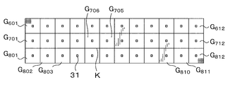
(開口部が閉じられたか否かの判定方法の他の例)
図4に示すように複数のグレーチングGが取り外された場合において、グレーチングGを戻したときに図5に示すように位置が入れ替わることがある。図5の例では、グレーチングG705とグレーチングG706とを戻したときにこれらの位置が入れ替わっている。
この場合、開口部が存在しないが、開口部が閉じられたか否かの判定方法として、前述の方法(各グレーチングGの水平面内での位置に基づいて判定する方法や現在のグレーチングGの配列に基づいて判定する方)では開口部が存在すると判定される。
これを避けるため、開口部が閉じられたか否かの判定は、取り外されたグレーチングGの現在の高さ方向の位置が正常状態の高さ方向の位置に一致するか否かの判定結果に基づいて行ってもよい。なお、正常状態における各グレーチングGの高さ方向の位置の情報は正常状態情報記憶部23bに記憶される。
また、この例の場合、開口部が閉じられたと判定されたときは、正常状態情報記憶部23bに記憶の正常状態情報を、開口部が閉じられたと判定されたときの情報に更新するとよい。 (Another example of the method for determining whether or not the opening is closed)
When the plurality of gratings G are removed as shown in FIG. 4, the positions may be switched as shown in FIG. 5 when the gratings G are returned. In the example of FIG. 5, when the grating G 705 and the grating G 706 are returned, their positions are exchanged.
In this case, there is no opening, but as a method for determining whether or not the opening is closed, the above-described method (the method based on the position of each grating G in the horizontal plane or the current arrangement of the grating G) is used. It is determined that there is an opening.
In order to avoid this, the determination as to whether or not the opening is closed is based on the determination result as to whether the current position in the height direction of the removed grating G matches the position in the normal height direction. You may go. The information on the position in the height direction of each grating G in the normal state is stored in the normal stateinformation storage unit 23b.
Further, in the case of this example, when it is determined that the opening is closed, the normal state information stored in the normal stateinformation storage unit 23b may be updated to the information when it is determined that the opening is closed.
図4に示すように複数のグレーチングGが取り外された場合において、グレーチングGを戻したときに図5に示すように位置が入れ替わることがある。図5の例では、グレーチングG705とグレーチングG706とを戻したときにこれらの位置が入れ替わっている。
この場合、開口部が存在しないが、開口部が閉じられたか否かの判定方法として、前述の方法(各グレーチングGの水平面内での位置に基づいて判定する方法や現在のグレーチングGの配列に基づいて判定する方)では開口部が存在すると判定される。
これを避けるため、開口部が閉じられたか否かの判定は、取り外されたグレーチングGの現在の高さ方向の位置が正常状態の高さ方向の位置に一致するか否かの判定結果に基づいて行ってもよい。なお、正常状態における各グレーチングGの高さ方向の位置の情報は正常状態情報記憶部23bに記憶される。
また、この例の場合、開口部が閉じられたと判定されたときは、正常状態情報記憶部23bに記憶の正常状態情報を、開口部が閉じられたと判定されたときの情報に更新するとよい。 (Another example of the method for determining whether or not the opening is closed)
When the plurality of gratings G are removed as shown in FIG. 4, the positions may be switched as shown in FIG. 5 when the gratings G are returned. In the example of FIG. 5, when the grating G 705 and the grating G 706 are returned, their positions are exchanged.
In this case, there is no opening, but as a method for determining whether or not the opening is closed, the above-described method (the method based on the position of each grating G in the horizontal plane or the current arrangement of the grating G) is used. It is determined that there is an opening.
In order to avoid this, the determination as to whether or not the opening is closed is based on the determination result as to whether the current position in the height direction of the removed grating G matches the position in the normal height direction. You may go. The information on the position in the height direction of each grating G in the normal state is stored in the normal state
Further, in the case of this example, when it is determined that the opening is closed, the normal state information stored in the normal state
(アンテナ21の位置の他の例)
図6は、アンテナ21の取り付け位置の他の例を説明するための図である。
上述の例では、アンテナ21は、基板処理装置2の筐体2aに取り付けられていた。しかし、アンテナ21の取り付け位置は、この例に限られない。アンテナ21は、例えばクリーンルームの天井Rに取り付けられてもよい。また、アンテナ21は、クリーンルーム内を移動する移動体に取り付けられてもよい。上記移動体とは、例えば、クリーンルーム内において、天井Rに沿って移動するOHT100や、グレーチングGにより構成される床上を走行するAGV101である。 (Another example of the position of the antenna 21)
FIG. 6 is a diagram for explaining another example of the mounting position of theantenna 21.
In the above-described example, theantenna 21 is attached to the housing 2a of the substrate processing apparatus 2. However, the mounting position of the antenna 21 is not limited to this example. The antenna 21 may be attached to the ceiling R of a clean room, for example. Further, the antenna 21 may be attached to a moving body that moves in the clean room. The moving body is, for example, an OHT 100 that moves along a ceiling R or an AGV 101 that runs on a floor formed by a grating G in a clean room.
図6は、アンテナ21の取り付け位置の他の例を説明するための図である。
上述の例では、アンテナ21は、基板処理装置2の筐体2aに取り付けられていた。しかし、アンテナ21の取り付け位置は、この例に限られない。アンテナ21は、例えばクリーンルームの天井Rに取り付けられてもよい。また、アンテナ21は、クリーンルーム内を移動する移動体に取り付けられてもよい。上記移動体とは、例えば、クリーンルーム内において、天井Rに沿って移動するOHT100や、グレーチングGにより構成される床上を走行するAGV101である。 (Another example of the position of the antenna 21)
FIG. 6 is a diagram for explaining another example of the mounting position of the
In the above-described example, the
(通信部の他の例)
以上の例では、監視対象の各グレーチングGに取り付けられ、当該グレーチングGの位置を検出するための通信を行う通信部として、パッシブ型無線ICタグであるRFIDタグ31が用いられていた。しかし、通信部は、無線LAN、Bluetooth(登録商標)、ZigBee(登録商標)等を用いて通信するアクティブ型無線ICタグであってもよい。
なお、アクティブ型無線ICタグからは一定期間毎に前述の識別情報を含む信号波が送出されている。したがって、RFIDタグ31を用いた場合に当該RFIDタグ31から上記信号波を送出させるのに必要であった、アンテナ21からの変調波の放射は不要となる。 (Other example of communication section)
In the above example, theRFID tag 31 which is a passive wireless IC tag is used as a communication unit attached to each grating G to be monitored and performing communication for detecting the position of the grating G. However, the communication unit may be an active wireless IC tag that communicates using a wireless LAN, Bluetooth (registered trademark), ZigBee (registered trademark), or the like.
A signal wave including the above-mentioned identification information is transmitted from the active wireless IC tag at regular intervals. Therefore, when theRFID tag 31 is used, it is unnecessary to radiate the modulated wave from the antenna 21, which is necessary to send the signal wave from the RFID tag 31.
以上の例では、監視対象の各グレーチングGに取り付けられ、当該グレーチングGの位置を検出するための通信を行う通信部として、パッシブ型無線ICタグであるRFIDタグ31が用いられていた。しかし、通信部は、無線LAN、Bluetooth(登録商標)、ZigBee(登録商標)等を用いて通信するアクティブ型無線ICタグであってもよい。
なお、アクティブ型無線ICタグからは一定期間毎に前述の識別情報を含む信号波が送出されている。したがって、RFIDタグ31を用いた場合に当該RFIDタグ31から上記信号波を送出させるのに必要であった、アンテナ21からの変調波の放射は不要となる。 (Other example of communication section)
In the above example, the
A signal wave including the above-mentioned identification information is transmitted from the active wireless IC tag at regular intervals. Therefore, when the
(位置検出の他の例)
以上の例では、グレーチングGの位置検出を、グレーチングGに取り付けられた無線ICタグからの信号波の強度等に基づいて行っていた。しかし、グレーチングGの位置検出の方法はこの方法に限られず、光学式屋内GPSを用いた方法であってもよい。この方法を用いる場合、グレーチングGの位置を検出するための通信を行う通信部として、光学式屋内GPS用の受信機が用いられる。 (Other example of position detection)
In the above example, the position of the grating G is detected based on the intensity of the signal wave from the wireless IC tag attached to the grating G and the like. However, the method of detecting the position of the grating G is not limited to this method, and may be a method using an optical indoor GPS. When this method is used, an optical indoor GPS receiver is used as a communication unit that performs communication for detecting the position of the grating G.
図7は、光学式屋内GPSを用いてグレーチングGの位置検出を行う場合における、監視システム1の全体構成の概略を示す平面図である。図8は、光学式屋内GPSを用いてグレーチングGの位置検出を行う場合における、監視装置としての基板処理装置2の監視処理にかかる構成の概略を示すブロック図である。
本例の監視システム1は、図7に示すように、光学式屋内GPS用の複数のレーザ発振機41が、監視対象の領域(グレーチングG601~グレーチングG612、グレーチングG701~グレーチングG712、グレーチングG801~グレーチングG812)を囲むように設けられている。また、監視対象のグレーチングGそれぞれに、光学式屋内GPS用の受信機としての光学センサ42が、レーザ発振機41からの光を受光可能に、取り付けられている。なお、各レーザ発振機41は、例えば後述の制御部44の制御により、予め定められたタイミングでパルスレーザ光を出射し、各光学センサ42は受光結果をA/D変換して出力する。 FIG. 7 is a plan view showing the outline of the overall configuration of themonitoring system 1 when the position of the grating G is detected using the optical indoor GPS. FIG. 8 is a block diagram showing an outline of a configuration related to a monitoring process of the substrate processing apparatus 2 as a monitoring device when the position of the grating G is detected using the optical indoor GPS.
In themonitoring system 1 of the present example, as shown in FIG. 7, a plurality of laser oscillators 41 for optical indoor GPS are used to monitor regions (grating G 601 to grating G 612 , grating G 701 to grating G 712 , It is provided so as to surround the grating G 801 to the grating G 812 . Further, an optical sensor 42 as a receiver for an optical indoor GPS is attached to each of the gratings G to be monitored so that the light from the laser oscillator 41 can be received. Each laser oscillator 41 emits pulsed laser light at a predetermined timing, for example, under the control of the control unit 44 described later, and each optical sensor 42 A/D-converts the light reception result and outputs it.
本例の監視システム1は、図7に示すように、光学式屋内GPS用の複数のレーザ発振機41が、監視対象の領域(グレーチングG601~グレーチングG612、グレーチングG701~グレーチングG712、グレーチングG801~グレーチングG812)を囲むように設けられている。また、監視対象のグレーチングGそれぞれに、光学式屋内GPS用の受信機としての光学センサ42が、レーザ発振機41からの光を受光可能に、取り付けられている。なお、各レーザ発振機41は、例えば後述の制御部44の制御により、予め定められたタイミングでパルスレーザ光を出射し、各光学センサ42は受光結果をA/D変換して出力する。 FIG. 7 is a plan view showing the outline of the overall configuration of the
In the
図8に示すように、本例の監視装置としての基板処理装置2は、位置算出エンジン43及び制御部44等を有する。
As shown in FIG. 8, the substrate processing apparatus 2 as the monitoring apparatus of this example has a position calculation engine 43, a control unit 44, and the like.
位置算出エンジン43は、各光学センサ42と通信し、各光学センサ42での受光強度等に基づいて、各光学センサ42の位置を算出することで、各グレーチングGの位置を検出する。なお、位置算出エンジン43と各光学センサ42とは無線接続されている。
位置算出エンジン43での位置検出結果は、グレーチングGの正常状態情報として用いられたり、後述の判定部44aでの判定に用いられたりする。 Theposition calculation engine 43 communicates with each optical sensor 42, and detects the position of each grating G by calculating the position of each optical sensor 42 based on the received light intensity at each optical sensor 42. The position calculation engine 43 and each optical sensor 42 are wirelessly connected.
The position detection result of theposition calculation engine 43 is used as the normal state information of the grating G, or used for the judgment by the judgment unit 44a described later.
位置算出エンジン43での位置検出結果は、グレーチングGの正常状態情報として用いられたり、後述の判定部44aでの判定に用いられたりする。 The
The position detection result of the
制御部44は、制御部23と同様、例えばCPUやメモリ等を備えたコンピュータである。また、制御部44は、監視処理を実現させるためのプログラムの指示に従ったCPUの処理により、判定部44a等が実装される。
Like the control unit 23, the control unit 44 is a computer including, for example, a CPU and a memory. Further, the control unit 44 is mounted with the determination unit 44a and the like by the processing of the CPU according to the instruction of the program for realizing the monitoring processing.
判定部44aは、位置算出エンジン43による、現在のグレーチングGの位置の検出結果と、正常状態情報記憶部23bに記憶されている、グレーチングGの正常状態情報とに基づいて、床の監視対象領域に開口部が存在するか判定する。
The determination unit 44a determines the floor monitoring target area based on the detection result of the current position of the grating G by the position calculation engine 43 and the normal state information of the grating G stored in the normal state information storage unit 23b. It is determined whether or not there is an opening.
本例の監視装置としての基板処理装置2においても、判定部44aによる判定結果に応じて、警報部24及び表示部25から出力がなされる。
Also in the substrate processing apparatus 2 as the monitoring apparatus of this example, the alarm unit 24 and the display unit 25 output according to the determination result by the determination unit 44a.
(正常状態情報記憶部及び判定部の他の例)
図2等を用いて説明した例では、正常状態情報は、制御部23の正常状態情報記憶部23bに記憶され、開口部の有無の判定は制御部23の判定部23cで行っていた。
これに代えて、リーダライタ22を用いて、正常状態情報を各RFIDタグ31に書き込み記憶させ、監視時は各RFIDタグ31から識別情報と共に正常状態情報が取得されるようにし、開口部の有無をリーダライタ22で行うようにしてもよい。
これにより、上位コントローラである制御部23の負荷を減らすことができる。 (Other examples of normal state information storage unit and determination unit)
In the example described with reference to FIG. 2 and the like, the normal state information is stored in the normal stateinformation storage unit 23b of the control unit 23, and the determination unit 23c of the control unit 23 determines whether or not there is an opening.
Instead, the reader/writer 22 is used to write and store the normal state information in each RFID tag 31, and the normal state information is acquired together with the identification information from each RFID tag 31 at the time of monitoring. May be performed by the reader/writer 22.
As a result, the load on thecontrol unit 23, which is the host controller, can be reduced.
図2等を用いて説明した例では、正常状態情報は、制御部23の正常状態情報記憶部23bに記憶され、開口部の有無の判定は制御部23の判定部23cで行っていた。
これに代えて、リーダライタ22を用いて、正常状態情報を各RFIDタグ31に書き込み記憶させ、監視時は各RFIDタグ31から識別情報と共に正常状態情報が取得されるようにし、開口部の有無をリーダライタ22で行うようにしてもよい。
これにより、上位コントローラである制御部23の負荷を減らすことができる。 (Other examples of normal state information storage unit and determination unit)
In the example described with reference to FIG. 2 and the like, the normal state information is stored in the normal state
Instead, the reader/
As a result, the load on the
(第2実施形態)
図9は、第2実施形態にかかる監視装置を説明するための図であり、クリーンルームの床を構成するグレーチングGの側面を示している。
本実施形態では、図9に示すように、各グレーチングGに、当該グレーチングGの位置検出用のRFIDタグ31の他に、動作検知部としての加速度センサ及びジャイロセンサを内蔵するアクティブ型無線ICタグ50が取り付けられている。アクティブ型無線ICタグ50は、加速度センサ及びジャイロセンサでのグレーチングGに対する動作検知結果を含む信号波を一定期間毎に放射し、この信号波は、監視装置のアンテナを介して受信される。 (Second embodiment)
FIG. 9 is a diagram for explaining the monitoring device according to the second embodiment, and shows the side surface of the grating G that constitutes the floor of the clean room.
In the present embodiment, as shown in FIG. 9, in each grating G, in addition to theRFID tag 31 for detecting the position of the grating G, an active type wireless IC tag including an acceleration sensor and a gyro sensor as an operation detection unit is incorporated. 50 is attached. The active wireless IC tag 50 radiates a signal wave including a motion detection result for the grating G in the acceleration sensor and the gyro sensor at regular intervals, and the signal wave is received via the antenna of the monitoring device.
図9は、第2実施形態にかかる監視装置を説明するための図であり、クリーンルームの床を構成するグレーチングGの側面を示している。
本実施形態では、図9に示すように、各グレーチングGに、当該グレーチングGの位置検出用のRFIDタグ31の他に、動作検知部としての加速度センサ及びジャイロセンサを内蔵するアクティブ型無線ICタグ50が取り付けられている。アクティブ型無線ICタグ50は、加速度センサ及びジャイロセンサでのグレーチングGに対する動作検知結果を含む信号波を一定期間毎に放射し、この信号波は、監視装置のアンテナを介して受信される。 (Second embodiment)
FIG. 9 is a diagram for explaining the monitoring device according to the second embodiment, and shows the side surface of the grating G that constitutes the floor of the clean room.
In the present embodiment, as shown in FIG. 9, in each grating G, in addition to the
そして、本実施形態では、監視装置が有する、床における開口部の有無の判定を行う判定部が、以下の(A)~(C)を基に、上記判定を行う。
(A)RFIDタグ31からの信号波の受信結果に基づいて検出された、現在の各グレーチングGの位置
(B)正常状態情報記憶部に記憶の正常状態情報
(C)加速度センサ及びジャイロセンサでの検知結果 Then, in the present embodiment, the determination unit that is included in the monitoring device and determines whether or not there is an opening in the floor makes the above determination based on the following (A) to (C).
(A) Current position of each grating G detected based on the reception result of the signal wave from the RFID tag 31 (B) Normal state information stored in the normal state information storage unit (C) Accelerometer and gyro sensor Detection result
例えば、一部のグレーチングGの位置が正常状態の位置と一致しない場合は、当該グレーチングGについての加速度センサ及びジャイロセンサによる動作検知結果によらず、上記開口部が存在すると判定される。また、一部のグレーチングGに対する動作が加速度センサ及びジャイロセンサによって検知された場合は、当該グレーチングGの位置が正常状態の位置と一致するか否かによらず、上記開口部が存在すると判定される。
For example, if the positions of some of the gratings G do not match the positions in the normal state, it is determined that the opening is present regardless of the result of motion detection of the grating G by the acceleration sensor and the gyro sensor. Further, when the motion for a part of the grating G is detected by the acceleration sensor and the gyro sensor, it is determined that the opening is present regardless of whether or not the position of the grating G matches the position in the normal state. It
本実施形態によれば、RFIDタグ31を用いた上記開口部の有無の判定と、動作検知部を用いた上記開口部の有無の判定とのいずれか一方が、正常に行われない場合でも、少なくとも開口部が存在するときには、より確実に開口部が存在すると判定することができる。つまり、本実施形態によれば、安全性をより高めることができる。
According to the present embodiment, even when one of the determination of the presence/absence of the opening using the RFID tag 31 and the determination of the presence/absence of the opening using the motion detection unit is not normally performed, When at least the opening is present, it can be more reliably determined that the opening is present. That is, according to this embodiment, safety can be further improved.
(動作検知部の他の例)
図10は、動作検知部の他の例を説明する図である。
図10の例では、動作検知部としての重量センサ(圧力センサ)を内蔵するアクティブ型無線ICタグ60が、グレーチングGの載置部分Gpそれぞれに取り付けられている。 (Other example of motion detector)
FIG. 10 is a diagram illustrating another example of the motion detector.
In the example of FIG. 10, an activewireless IC tag 60 having a built-in weight sensor (pressure sensor) as an operation detection unit is attached to each mounting portion Gp of the grating G.
図10は、動作検知部の他の例を説明する図である。
図10の例では、動作検知部としての重量センサ(圧力センサ)を内蔵するアクティブ型無線ICタグ60が、グレーチングGの載置部分Gpそれぞれに取り付けられている。 (Other example of motion detector)
FIG. 10 is a diagram illustrating another example of the motion detector.
In the example of FIG. 10, an active
(第3実施形態)
図11は、第3実施形態にかかる監視装置を説明するための図である。
第1実施形態では、基板処理装置2が監視装置を兼ねていた。それに対し、図11の監視システム1では、作業者Wが有する携帯型端末装置Mが監視装置として機能する。
具体的には、携帯型端末装置Mが、図2を用いて説明した、アンテナ21、リーダライタ22、制御部23、警報部24及び表示部25を有する。そして、携帯型端末装置Mのアンテナ21を介して受信した結果に基づいて、開口部が存在すると判定された場合、例えば警報部24から音による警報や、表示部25による開口部の位置を示す画像の表示が行われる。
なお、本実施形態の場合、開口部の有無の判定は、現在のグレーチングの配列が正常状態のものに一致するかに基づいて行うことが好ましい。なぜならば、携帯型端末装置Mの向きが変わり、アンテナ21の向きが変わっても、開口部の有無の判定に、正常状態情報記憶部23bに記憶の正常状態情報をそのまま利用でき、アンテナ21の向きの変更直後であっても当該判定を正確に行うことができるからである。 (Third Embodiment)
FIG. 11 is a diagram for explaining the monitoring device according to the third embodiment.
In the first embodiment, thesubstrate processing apparatus 2 also serves as the monitoring device. On the other hand, in the monitoring system 1 of FIG. 11, the portable terminal device M of the worker W functions as a monitoring device.
Specifically, the mobile terminal device M includes theantenna 21, the reader/writer 22, the control unit 23, the alarm unit 24, and the display unit 25 described with reference to FIG. Then, when it is determined that the opening is present based on the result received via the antenna 21 of the mobile terminal device M, for example, a warning is given by a sound from the alarm unit 24 or the position of the opening by the display unit 25 is indicated. The image is displayed.
In the case of the present embodiment, it is preferable that the presence/absence of the opening be determined based on whether the current arrangement of gratings matches the normal arrangement. This is because even if the orientation of the mobile terminal device M changes and the orientation of theantenna 21 changes, the normal state information stored in the normal state information storage unit 23b can be used as it is for determining whether or not there is an opening, and This is because the determination can be accurately made even immediately after changing the orientation.
図11は、第3実施形態にかかる監視装置を説明するための図である。
第1実施形態では、基板処理装置2が監視装置を兼ねていた。それに対し、図11の監視システム1では、作業者Wが有する携帯型端末装置Mが監視装置として機能する。
具体的には、携帯型端末装置Mが、図2を用いて説明した、アンテナ21、リーダライタ22、制御部23、警報部24及び表示部25を有する。そして、携帯型端末装置Mのアンテナ21を介して受信した結果に基づいて、開口部が存在すると判定された場合、例えば警報部24から音による警報や、表示部25による開口部の位置を示す画像の表示が行われる。
なお、本実施形態の場合、開口部の有無の判定は、現在のグレーチングの配列が正常状態のものに一致するかに基づいて行うことが好ましい。なぜならば、携帯型端末装置Mの向きが変わり、アンテナ21の向きが変わっても、開口部の有無の判定に、正常状態情報記憶部23bに記憶の正常状態情報をそのまま利用でき、アンテナ21の向きの変更直後であっても当該判定を正確に行うことができるからである。 (Third Embodiment)
FIG. 11 is a diagram for explaining the monitoring device according to the third embodiment.
In the first embodiment, the
Specifically, the mobile terminal device M includes the
In the case of the present embodiment, it is preferable that the presence/absence of the opening be determined based on whether the current arrangement of gratings matches the normal arrangement. This is because even if the orientation of the mobile terminal device M changes and the orientation of the
なお、本実施形態では、振動する振動部を携帯型端末装置Mに設けておき、開口部が存在すると判定された場合に、作業者Wに振動で警告するようにしてもよい。
また、本実施形態において、制御部23、警報部24及び表示部25の監視処理にかかる機能は、基板処理装置2に設けるようにしてもよい。 In the present embodiment, a vibrating vibrating unit may be provided in the mobile terminal device M, and when it is determined that the opening is present, the worker W may be warned by the vibration.
Further, in the present embodiment, the functions related to the monitoring processing of thecontrol unit 23, the alarm unit 24, and the display unit 25 may be provided in the substrate processing apparatus 2.
また、本実施形態において、制御部23、警報部24及び表示部25の監視処理にかかる機能は、基板処理装置2に設けるようにしてもよい。 In the present embodiment, a vibrating vibrating unit may be provided in the mobile terminal device M, and when it is determined that the opening is present, the worker W may be warned by the vibration.
Further, in the present embodiment, the functions related to the monitoring processing of the
以上の例では、監視対象のグレーチングを基板処理装置の周囲としていたが、基板処理装置周囲以外の部分のグレーチングを監視対象としてもよい。また、基板処理装置が載置される前のクリーンルーム内全体を監視対象としてもよい。
In the above example, the grating to be monitored is around the substrate processing apparatus, but the gratings other than the area around the substrate processing apparatus may be monitored. Moreover, the entire clean room before the substrate processing apparatus is placed may be monitored.
また、以上の例では、開口部の有無の判定に、グレーチングGに取り付けられたRFIDタグ31等の通信部に記憶された識別情報を用いていた。しかし、当該識別情報を用いなくてもよい。
識別情報を用いない場合でも、どのグレーチングの位置かは判別できないが、グレーチングの位置自体は検出できる。したがって、識別情報を用いない場合は、例えば、監視対象の全グレーチングの位置情報の集合が、現在と正常状態とで相違するか否かに基づいて、開口部の有無を判定してもよい。 Further, in the above example, the identification information stored in the communication unit such as theRFID tag 31 attached to the grating G is used to determine the presence or absence of the opening. However, the identification information may not be used.
Even if the identification information is not used, it is not possible to determine which grating position, but the grating position itself can be detected. Therefore, when the identification information is not used, for example, the presence or absence of the opening may be determined based on whether or not the set of position information of all the monitored gratings is different between the current state and the normal state.
識別情報を用いない場合でも、どのグレーチングの位置かは判別できないが、グレーチングの位置自体は検出できる。したがって、識別情報を用いない場合は、例えば、監視対象の全グレーチングの位置情報の集合が、現在と正常状態とで相違するか否かに基づいて、開口部の有無を判定してもよい。 Further, in the above example, the identification information stored in the communication unit such as the
Even if the identification information is not used, it is not possible to determine which grating position, but the grating position itself can be detected. Therefore, when the identification information is not used, for example, the presence or absence of the opening may be determined based on whether or not the set of position information of all the monitored gratings is different between the current state and the normal state.
なお、本開示に係る技術は、クリーンルーム以外の空間の床に適用することができ、また、グレーチング以外の床部材により構成される床にも適用することができる。
Note that the technology according to the present disclosure can be applied to a floor in a space other than a clean room, and can also be applied to a floor configured by floor members other than grating.
今回開示された実施形態はすべての点で例示であって制限的なものではないと考えられるべきである。上記の実施形態は、添付の請求の範囲及びその主旨を逸脱することなく、様々な形態で省略、置換、変更されてもよい。
The embodiments disclosed this time are to be considered as illustrative in all points and not restrictive. The above-described embodiments may be omitted, replaced, or modified in various forms without departing from the scope and spirit of the appended claims.
なお、以下のような構成も本開示の技術的範囲に属する。
Note that the following configurations also belong to the technical scope of the present disclosure.
(1)クリーンルーム内のグレーチングにより構成される床を監視する監視装置であって、
グレーチングのそれぞれには、当該グレーチングの位置を検出するための通信を行う通信部が取り付けられており、
当該監視装置は、
前記通信部との通信結果を用いた現在のグレーチングの位置の検出結果と、グレーチングが取り外されて生じる開口部が存在しない正常状態のグレーチングの位置に関する情報と、に基づいて、前記開口部の有無の判定を行う判定部と、
前記判定部での前記開口部の有無の判定結果に応じて出力を行う出力部と、を有する、監視装置。
前記(1)によれば、現場にいる作業員は、開口部が存在することを直ちに知ることができる。それゆえ作業中であっても、警報が発せられている間は開口部が存在すると知覚して、作業を行うことになり、誤って開口部から落ちてしまうという事態を防止できる。また、監視カメラ等の高価な装置が不要であるため、前記(1)による監視システムは低コストで構築することができる。さらに、前記(1)による監視システムは、構築作業が極めて簡単、かつ迅速に行うことができる。 (1) A monitoring device for monitoring a floor configured by grating in a clean room,
Each grating is equipped with a communication unit that performs communication for detecting the position of the grating.
The monitoring device is
The presence or absence of the opening based on the detection result of the current position of the grating using the communication result with the communication unit and the information on the position of the grating in the normal state where the opening caused by the removal of the grating does not exist. A determination unit for determining
An output unit that outputs according to the determination result of the presence or absence of the opening in the determination unit.
According to the above (1), the worker on site can immediately know that the opening exists. Therefore, even during the work, it is possible to prevent the situation in which the user perceives that the opening exists while the alarm is being issued and performs the work, and accidentally falls from the opening. Further, since an expensive device such as a surveillance camera is unnecessary, the surveillance system according to (1) above can be constructed at low cost. Furthermore, the monitoring system according to (1) above can be constructed very easily and quickly.
(2)前記判定部は、現在のグレーチングの位置が前記正常状態の位置と一致するかに基づいて、前記開口部の有無の判定を行う、前記(1)に記載の監視装置。
(2) The monitoring device according to (1), wherein the determination unit determines the presence or absence of the opening based on whether the current position of grating matches the position in the normal state.
(3)前記判定部は、現在のグレーチングの配列が前記正常状態の配列と一致するかに基づいて、前記開口部の有無の判定を行う、前記(1)に記載の監視装置。
(3) The monitoring device according to (1), wherein the determination unit determines the presence or absence of the opening based on whether the current grating arrangement matches the normal arrangement.
(4)前記判定部は、現在のグレーチングの間隔が前記正常状態の間隔と一致するかに基づいて、前記開口部の有無の判定を行う、前記(1)に記載の監視装置。
(4) The monitoring device according to (1), wherein the determination unit determines the presence or absence of the opening based on whether a current grating interval matches an interval in the normal state.
(5)前記判定部は、
さらに、前記開口部が閉じられたか否かの判定を行い、
前記開口部が形成された後、現在のグレーチングの高さ方向にかかる位置が前記正常状態の位置と一致した場合に、前記開口部が閉じられたと判定する、前記(2)または(3)に記載の監視装置。 (5) The determination unit is
Furthermore, it is determined whether or not the opening is closed,
After the opening is formed, when the current position in the height direction of the grating matches the position in the normal state, it is determined that the opening is closed. (2) or (3) The monitoring device described.
(6)グレーチングに対し、当該グレーチングに対する動作を検知する動作検知部が設けられており、
前記判定部は、現在のグレーチングの位置の検出結果と、前記正常状態のグレーチングの位置に関する情報と、前記動作検知部での検知結果と、に基づいて、前記開口部の有無の判定を行う、前記(1)に記載の監視装置。
前記(6)によればさらに安全性を高めることができる。 (6) For the grating, a motion detector that detects a motion for the grating is provided,
The determination unit determines the presence or absence of the opening based on the detection result of the current grating position, information about the position of the grating in the normal state, and the detection result of the operation detecting unit. The monitoring device according to (1) above.
According to the above (6), the safety can be further enhanced.
(7)前記通信部からの信号を受信する受信部は、クリーンルーム内の床上に設置される基板処理装置に設けられている、前記(1)~(6)のいずれか1に記載の監視装置。
(7) The monitoring device according to any one of (1) to (6), wherein the receiving unit that receives a signal from the communication unit is provided in a substrate processing apparatus installed on a floor in a clean room. ..
(8)前記通信部からの信号を受信する受信部は、クリーンルームの天井に設けられている、前記(1)~(6)のいずれか1に記載の監視装置。
(8) The monitoring device according to any one of (1) to (6), wherein the receiving unit that receives a signal from the communication unit is provided on a ceiling of a clean room.
(9)前記通信部からの信号を受信する受信部は、携帯型端末装置に設けられている、前記(1)~(6)のいずれか1に記載の監視装置。
(9) The monitoring device according to any one of (1) to (6), wherein the receiving unit that receives the signal from the communication unit is provided in the mobile terminal device.
(10)前記通信部からの信号を受信する受信部は、クリーンルーム内を移動する移動体に設けられている、前記(1)~(6)のいずれか1に記載の監視装置。
(10) The monitoring device according to any one of (1) to (6), wherein the receiving unit that receives a signal from the communication unit is provided in a moving body that moves in a clean room.
(11)前記出力部は、前記開口部が存在する場合に、光及び音の少なくともいずれか一方による警報を発する警報器である、前記(1)~(10)のいずれか1に記載の監視装置。
(11) The monitoring according to any one of (1) to (10), wherein the output unit is an alarm device that issues an alarm by at least one of light and sound when the opening is present. apparatus.
(12)前記出力部は、前記開口部が存在する場合に、当該開口部が存在することを示す画像及び当該開口部の位置を示す画像の少なくともいずれか一方を表示する表示部である、前記(1)~(11)のいずれか1に記載の監視装置。
(12) The output unit is a display unit that displays at least one of an image indicating the presence of the opening and an image indicating the position of the opening when the opening is present, The monitoring device according to any one of (1) to (11).
(13)前記通信部は、パッシブ型の無線ICタグである、前記(1)~(12)のいずれか1に記載の監視装置。
(13) The monitoring device according to any one of (1) to (12), wherein the communication unit is a passive wireless IC tag.
(14)前記通信部は、アクティブ型の無線ICタグである、前記(1)~(12)のいずれか1に記載の監視装置。
(14) The monitoring device according to any one of (1) to (12), wherein the communication unit is an active wireless IC tag.
(15)前記通信部は、光学式屋内GPSの受信機である、前記(1)~(12)のいずれか1に記載の監視装置。
(15) The monitoring device according to any one of (1) to (12), wherein the communication unit is an optical indoor GPS receiver.
(16)クリーンルーム内のグレーチングにより構成される床を監視する監視方法であって、
グレーチングのそれぞれには、当該グレーチングの位置を検出するための通信を行う通信部が取り付けられており、
当該監視方法は、
前記通信部との通信結果に基づいて、現在のグレーチングの位置の検出を行う工程と、
前記検出の結果と、グレーチングが取り外されて生じる開口部が存在しない正常状態のグレーチングの位置に関する情報とに基づいて、前記開口部の有無の判定を行う工程と、
前記開口部の有無の判定結果に応じて出力を行う出力工程と、を有する、監視方法。 (16) A monitoring method for monitoring a floor configured by grating in a clean room,
Each grating is equipped with a communication unit that performs communication for detecting the position of the grating.
The monitoring method is
A step of detecting the current position of the grating based on the communication result with the communication unit;
Based on the result of the detection and the information about the position of the grating in a normal state in which the opening is not formed when the grating is removed, a step of determining the presence or absence of the opening,
An output step of outputting according to the determination result of the presence or absence of the opening, the monitoring method.
(17)基板を処理する基板処理装置であって、
当該基板処理装置は、クリーンルーム内のグレーチングにより構成される床上に載置されるものであり、
グレーチングのそれぞれには、当該グレーチングの位置を検出するための通信を行う通信部が取り付けられており、
当該基板処理装置は、
前記通信部との通信結果を用いた現在のグレーチングの位置の検出結果と、グレーチングが取り外されて生じる開口部が存在しない正常状態のグレーチングの位置に関する情報と、に基づいて、前記開口部の有無の判定を行う判定部と、
前記判定部での前記開口部の有無の判定結果に応じて出力を行う出力部と、を有する、基板処理装置。 (17) A substrate processing apparatus for processing a substrate, comprising:
The substrate processing apparatus is to be placed on a floor composed of grating in a clean room,
Each grating is equipped with a communication unit that performs communication for detecting the position of the grating.
The substrate processing apparatus is
The presence or absence of the opening based on the detection result of the current position of the grating using the communication result with the communication unit and the information on the position of the grating in the normal state where the opening caused by the removal of the grating does not exist. A determination unit for determining
A substrate processing apparatus, comprising: an output unit that outputs according to a determination result of the presence or absence of the opening in the determination unit.
2 基板処理装置
23c、44a 判定部
24 警報部
25 表示部
31 RFIDタグ
42 光学センサ
G グレーチング
K 開口部
M 携帯型端末装置 2 substrate processing devices 23c, 44a determination unit 24 alarm unit 25 display unit 31 RFID tag 42 optical sensor G grating K opening M portable terminal device
23c、44a 判定部
24 警報部
25 表示部
31 RFIDタグ
42 光学センサ
G グレーチング
K 開口部
M 携帯型端末装置 2
Claims (17)
- クリーンルーム内のグレーチングにより構成される床を監視する監視装置であって、
グレーチングのそれぞれには、当該グレーチングの位置を検出するための通信を行う通信部が取り付けられており、
当該監視装置は、
前記通信部との通信結果を用いた現在のグレーチングの位置の検出結果と、グレーチングが取り外されて生じる開口部が存在しない正常状態のグレーチングの位置に関する情報と、に基づいて、前記開口部の有無の判定を行う判定部と、
前記判定部での前記開口部の有無の判定結果に応じて出力を行う出力部と、を有する、監視装置。 A monitoring device for monitoring a floor composed of grating in a clean room,
Each grating is equipped with a communication unit that performs communication for detecting the position of the grating.
The monitoring device is
The presence or absence of the opening based on the detection result of the current position of the grating using the communication result with the communication unit and the information on the position of the grating in the normal state where the opening caused by the removal of the grating does not exist. A determination unit for determining
An output unit that outputs according to the determination result of the presence or absence of the opening in the determination unit. - 前記判定部は、現在のグレーチングの位置が前記正常状態の位置と一致するかに基づいて、前記開口部の有無の判定を行う、請求項1に記載の監視装置。 The monitoring device according to claim 1, wherein the determination unit determines the presence or absence of the opening based on whether the current position of grating matches the position of the normal state.
- 前記判定部は、現在のグレーチングの配列が前記正常状態の配列と一致するかに基づいて、前記開口部の有無の判定を行う、請求項1に記載の監視装置。 The monitoring device according to claim 1, wherein the determination unit determines the presence or absence of the opening based on whether the current array of gratings matches the array in the normal state.
- 前記判定部は、現在のグレーチングの間隔が前記正常状態の間隔と一致するかに基づいて、前記開口部の有無の判定を行う、請求項1に記載の監視装置。 The monitoring device according to claim 1, wherein the determination unit determines the presence or absence of the opening based on whether a current grating interval matches an interval in the normal state.
- 前記判定部は、
さらに、前記開口部が閉じられたか否かの判定を行い、
前記開口部が形成された後、現在のグレーチングの高さ方向にかかる位置が前記正常状態の位置と一致した場合に、前記開口部が閉じられたと判定する、請求項2または3に記載の監視装置。 The determination unit,
Furthermore, it is determined whether or not the opening is closed,
The monitoring according to claim 2 or 3, wherein after the opening is formed, when the current position in the height direction of the grating matches the position in the normal state, the opening is determined to be closed. apparatus. - グレーチングに対し、当該グレーチングに対する動作を検知する動作検知部が設けられており、
前記判定部は、現在のグレーチングの位置の検出結果と、前記正常状態のグレーチングの位置に関する情報と、前記動作検知部での検知結果と、に基づいて、前記開口部の有無の判定を行う、請求項1に記載の監視装置。 For grating, a motion detector that detects motion for the grating is provided,
The determination unit determines the presence or absence of the opening based on the detection result of the current grating position, information about the position of the grating in the normal state, and the detection result of the operation detecting unit. The monitoring device according to claim 1. - 前記通信部からの信号を受信する受信部は、クリーンルーム内の床上に設置される基板処理装置に設けられている、請求項1~6のいずれか1項に記載の監視装置。 The monitoring device according to any one of claims 1 to 6, wherein the receiving unit that receives a signal from the communication unit is provided in a substrate processing apparatus installed on a floor in a clean room.
- 前記通信部からの信号を受信する受信部は、クリーンルームの天井に設けられている、請求項1~6のいずれか1項に記載の監視装置。 The monitoring device according to any one of claims 1 to 6, wherein a receiving unit that receives a signal from the communication unit is provided on a ceiling of a clean room.
- 前記通信部からの信号を受信する受信部は、携帯型端末装置に設けられている、請求項1~6のいずれか1項に記載の監視装置。 The monitoring device according to any one of claims 1 to 6, wherein the receiving unit that receives a signal from the communication unit is provided in the mobile terminal device.
- 前記通信部からの信号を受信する受信部は、クリーンルーム内を移動する移動体に設けられている、請求項1~6のいずれか1項に記載の監視装置。 The monitoring device according to any one of claims 1 to 6, wherein the receiving unit that receives a signal from the communication unit is provided in a moving body that moves in a clean room.
- 前記出力部は、前記開口部が存在する場合に、光及び音の少なくともいずれか一方による警報を発する警報器である、請求項1~10のいずれか1項に記載の監視装置。 The monitoring device according to any one of claims 1 to 10, wherein the output unit is an alarm device that issues an alarm by at least one of light and sound when the opening is present.
- 前記出力部は、前記開口部が存在する場合に、当該開口部が存在することを示す画像及び当該開口部の位置を示す画像の少なくともいずれか一方を表示する表示部である、請求項1~11のいずれか1項に記載の監視装置。 The output unit is a display unit that displays at least one of an image indicating that the opening exists and an image indicating the position of the opening when the opening exists. 11. The monitoring device according to any one of 11.
- 前記通信部は、パッシブ型の無線ICタグである、請求項1~12のいずれか1項に記載の監視装置。 The monitoring device according to any one of claims 1 to 12, wherein the communication unit is a passive wireless IC tag.
- 前記通信部は、アクティブ型の無線ICタグである、請求項1~12のいずれか1項に記載の監視装置。 The monitoring device according to any one of claims 1 to 12, wherein the communication unit is an active wireless IC tag.
- 前記通信部は、光学式屋内GPSの受信機である、請求項1~12のいずれか1項に記載の監視装置。 The monitoring device according to any one of claims 1 to 12, wherein the communication unit is an optical indoor GPS receiver.
- クリーンルーム内のグレーチングにより構成される床を監視する監視方法であって、
グレーチングのそれぞれには、当該グレーチングの位置を検出するための通信を行う通信部が取り付けられており、
当該監視方法は、
前記通信部との通信結果に基づいて、現在のグレーチングの位置の検出を行う工程と、
前記検出の結果と、グレーチングが取り外されて生じる開口部が存在しない正常状態のグレーチングの位置に関する情報とに基づいて、前記開口部の有無の判定を行う工程と、
前記開口部の有無の判定結果に応じて出力を行う出力工程と、を有する、監視方法。 A monitoring method for monitoring a floor composed of grating in a clean room,
Each grating is equipped with a communication unit that performs communication for detecting the position of the grating.
The monitoring method is
A step of detecting the current position of the grating based on the communication result with the communication unit;
Based on the result of the detection and the information about the position of the grating in a normal state in which the opening is not formed when the grating is removed, a step of determining the presence or absence of the opening,
An output step of outputting according to the determination result of the presence or absence of the opening, the monitoring method. - 基板を処理する基板処理装置であって、
当該基板処理装置は、クリーンルーム内のグレーチングにより構成される床上に載置されるものであり、
グレーチングのそれぞれには、当該グレーチングの位置を検出するための通信を行う通信部が取り付けられており、
当該基板処理装置は、
前記通信部との通信結果を用いた現在のグレーチングの位置の検出結果と、グレーチングが取り外されて生じる開口部が存在しない正常状態のグレーチングの位置に関する情報と、に基づいて、前記開口部の有無の判定を行う判定部と、
前記判定部での前記開口部の有無の判定結果に応じて出力を行う出力部と、を有する、基板処理装置。 A substrate processing apparatus for processing a substrate, comprising:
The substrate processing apparatus is to be placed on a floor composed of grating in a clean room,
Each grating is equipped with a communication unit that performs communication for detecting the position of the grating.
The substrate processing apparatus is
The presence or absence of the opening based on the detection result of the current position of the grating using the communication result with the communication unit and the information on the position of the grating in the normal state where the opening caused by the removal of the grating does not exist. A determination unit for determining
A substrate processing apparatus, comprising: an output unit that outputs according to a determination result of the presence or absence of the opening in the determination unit.
Priority Applications (1)
| Application Number | Priority Date | Filing Date | Title |
|---|---|---|---|
| JP2020559231A JP7105319B2 (en) | 2018-12-13 | 2019-12-03 | MONITORING DEVICE, MONITORING METHOD, AND SUBSTRATE PROCESSING APPARATUS |
Applications Claiming Priority (2)
| Application Number | Priority Date | Filing Date | Title |
|---|---|---|---|
| JP2018-233612 | 2018-12-13 | ||
| JP2018233612 | 2018-12-13 |
Publications (1)
| Publication Number | Publication Date |
|---|---|
| WO2020121897A1 true WO2020121897A1 (en) | 2020-06-18 |
Family
ID=71075304
Family Applications (1)
| Application Number | Title | Priority Date | Filing Date |
|---|---|---|---|
| PCT/JP2019/047258 WO2020121897A1 (en) | 2018-12-13 | 2019-12-03 | Monitoring device, monitoring method, and substrate treatment device |
Country Status (3)
| Country | Link |
|---|---|
| JP (1) | JP7105319B2 (en) |
| TW (1) | TW202027044A (en) |
| WO (1) | WO2020121897A1 (en) |
Citations (2)
| Publication number | Priority date | Publication date | Assignee | Title |
|---|---|---|---|---|
| JP2014016799A (en) * | 2012-07-09 | 2014-01-30 | Tokyo Electron Ltd | Clean room monitoring device and clean room monitoring method |
| JP2017027306A (en) * | 2015-07-21 | 2017-02-02 | 株式会社Iro | Grating and fixture |
Family Cites Families (1)
| Publication number | Priority date | Publication date | Assignee | Title |
|---|---|---|---|---|
| JP7122187B2 (en) * | 2018-07-26 | 2022-08-19 | 東京エレクトロン株式会社 | Monitoring system around substrate processing equipment |
-
2019
- 2019-12-03 JP JP2020559231A patent/JP7105319B2/en active Active
- 2019-12-03 TW TW108144077A patent/TW202027044A/en unknown
- 2019-12-03 WO PCT/JP2019/047258 patent/WO2020121897A1/en active Application Filing
Patent Citations (2)
| Publication number | Priority date | Publication date | Assignee | Title |
|---|---|---|---|---|
| JP2014016799A (en) * | 2012-07-09 | 2014-01-30 | Tokyo Electron Ltd | Clean room monitoring device and clean room monitoring method |
| JP2017027306A (en) * | 2015-07-21 | 2017-02-02 | 株式会社Iro | Grating and fixture |
Also Published As
| Publication number | Publication date |
|---|---|
| JP7105319B2 (en) | 2022-07-22 |
| JPWO2020121897A1 (en) | 2021-10-14 |
| TW202027044A (en) | 2020-07-16 |
Similar Documents
| Publication | Publication Date | Title |
|---|---|---|
| US9269255B2 (en) | Worksite proximity warning | |
| AU2007317213B2 (en) | Protection, security and displacement-tracking luminous badge system | |
| US9227820B2 (en) | Sensor unit system | |
| US10360728B2 (en) | Augmented reality device, system, and method for safety | |
| RU2472226C2 (en) | Apparatus for monitoring location of individuals | |
| KR101339928B1 (en) | Integrated wireless ship management system based on local information of worker | |
| US11341830B2 (en) | Infrastructure construction digital integrated twin (ICDIT) | |
| KR100966735B1 (en) | Realtime monitoring system for guard based on bio signal and etc. | |
| KR101720857B1 (en) | Safety control system | |
| JP2019131392A (en) | Transport device, transport device with receiver, transportation system, host system, method of controlling transport device, and program | |
| JP2014146288A (en) | Surveillance system | |
| JP2008291519A (en) | Field control system and field control method | |
| KR20150083480A (en) | System for managing facilities by using 3d stereoscopic images | |
| KR20180011322A (en) | Equipment and methods for monitoring valves of hydraulic circuits, associated hydraulic circuits, and computer program products | |
| JP6621201B2 (en) | Digital signage system | |
| JP5961992B2 (en) | Worker management system | |
| JP2008146683A (en) | Network system, control node, fixed node, information processing method and program | |
| WO2020121897A1 (en) | Monitoring device, monitoring method, and substrate treatment device | |
| JP2015005152A (en) | Approach warning system for hanging load of crane and worker | |
| CN205943002U (en) | RFID location early warning system in operation place | |
| KR20210061227A (en) | Worker Safety Monitoring System in Shadow Area and Method thereof | |
| KR20120008840A (en) | The mobile station for a remote control excavator | |
| JP2019209426A (en) | Robot state monitoring system and robot state monitoring method | |
| JP2007157032A (en) | Monitoring system | |
| KR20130119159A (en) | Local information based wireless ship management system |
Legal Events
| Date | Code | Title | Description |
|---|---|---|---|
| 121 | Ep: the epo has been informed by wipo that ep was designated in this application |
Ref document number: 19897401 Country of ref document: EP Kind code of ref document: A1 |
|
| ENP | Entry into the national phase |
Ref document number: 2020559231 Country of ref document: JP Kind code of ref document: A |
|
| NENP | Non-entry into the national phase |
Ref country code: DE |
|
| 122 | Ep: pct application non-entry in european phase |
Ref document number: 19897401 Country of ref document: EP Kind code of ref document: A1 |