WO2020121707A1 - 電池モジュール - Google Patents
電池モジュール Download PDFInfo
- Publication number
- WO2020121707A1 WO2020121707A1 PCT/JP2019/044132 JP2019044132W WO2020121707A1 WO 2020121707 A1 WO2020121707 A1 WO 2020121707A1 JP 2019044132 W JP2019044132 W JP 2019044132W WO 2020121707 A1 WO2020121707 A1 WO 2020121707A1
- Authority
- WO
- WIPO (PCT)
- Prior art keywords
- cells
- battery module
- electrode tab
- layer
- laminate
- Prior art date
- Legal status (The legal status is an assumption and is not a legal conclusion. Google has not performed a legal analysis and makes no representation as to the accuracy of the status listed.)
- Ceased
Links
Images








Classifications
-
- H—ELECTRICITY
- H01—ELECTRIC ELEMENTS
- H01M—PROCESSES OR MEANS, e.g. BATTERIES, FOR THE DIRECT CONVERSION OF CHEMICAL ENERGY INTO ELECTRICAL ENERGY
- H01M50/00—Constructional details or processes of manufacture of the non-active parts of electrochemical cells other than fuel cells, e.g. hybrid cells
- H01M50/50—Current conducting connections for cells or batteries
-
- H—ELECTRICITY
- H01—ELECTRIC ELEMENTS
- H01M—PROCESSES OR MEANS, e.g. BATTERIES, FOR THE DIRECT CONVERSION OF CHEMICAL ENERGY INTO ELECTRICAL ENERGY
- H01M50/00—Constructional details or processes of manufacture of the non-active parts of electrochemical cells other than fuel cells, e.g. hybrid cells
- H01M50/20—Mountings; Secondary casings or frames; Racks, modules or packs; Suspension devices; Shock absorbers; Transport or carrying devices; Holders
- H01M50/204—Racks, modules or packs for multiple batteries or multiple cells
- H01M50/207—Racks, modules or packs for multiple batteries or multiple cells characterised by their shape
- H01M50/211—Racks, modules or packs for multiple batteries or multiple cells characterised by their shape adapted for pouch cells
-
- H—ELECTRICITY
- H01—ELECTRIC ELEMENTS
- H01M—PROCESSES OR MEANS, e.g. BATTERIES, FOR THE DIRECT CONVERSION OF CHEMICAL ENERGY INTO ELECTRICAL ENERGY
- H01M50/00—Constructional details or processes of manufacture of the non-active parts of electrochemical cells other than fuel cells, e.g. hybrid cells
- H01M50/20—Mountings; Secondary casings or frames; Racks, modules or packs; Suspension devices; Shock absorbers; Transport or carrying devices; Holders
- H01M50/298—Mountings; Secondary casings or frames; Racks, modules or packs; Suspension devices; Shock absorbers; Transport or carrying devices; Holders characterised by the wiring of battery packs
-
- H—ELECTRICITY
- H01—ELECTRIC ELEMENTS
- H01M—PROCESSES OR MEANS, e.g. BATTERIES, FOR THE DIRECT CONVERSION OF CHEMICAL ENERGY INTO ELECTRICAL ENERGY
- H01M50/00—Constructional details or processes of manufacture of the non-active parts of electrochemical cells other than fuel cells, e.g. hybrid cells
- H01M50/50—Current conducting connections for cells or batteries
- H01M50/569—Constructional details of current conducting connections for detecting conditions inside cells or batteries, e.g. details of voltage sensing terminals
-
- H—ELECTRICITY
- H01—ELECTRIC ELEMENTS
- H01M—PROCESSES OR MEANS, e.g. BATTERIES, FOR THE DIRECT CONVERSION OF CHEMICAL ENERGY INTO ELECTRICAL ENERGY
- H01M50/00—Constructional details or processes of manufacture of the non-active parts of electrochemical cells other than fuel cells, e.g. hybrid cells
- H01M50/50—Current conducting connections for cells or batteries
- H01M50/572—Means for preventing undesired use or discharge
-
- Y—GENERAL TAGGING OF NEW TECHNOLOGICAL DEVELOPMENTS; GENERAL TAGGING OF CROSS-SECTIONAL TECHNOLOGIES SPANNING OVER SEVERAL SECTIONS OF THE IPC; TECHNICAL SUBJECTS COVERED BY FORMER USPC CROSS-REFERENCE ART COLLECTIONS [XRACs] AND DIGESTS
- Y02—TECHNOLOGIES OR APPLICATIONS FOR MITIGATION OR ADAPTATION AGAINST CLIMATE CHANGE
- Y02E—REDUCTION OF GREENHOUSE GAS [GHG] EMISSIONS, RELATED TO ENERGY GENERATION, TRANSMISSION OR DISTRIBUTION
- Y02E60/00—Enabling technologies; Technologies with a potential or indirect contribution to GHG emissions mitigation
- Y02E60/10—Energy storage using batteries
Definitions
- the present invention relates to a battery module in which a plurality of substantially rectangular thin plate-shaped laminated cells are connected in series.
- Non-aqueous electrolyte batteries typified by lithium-ion secondary batteries are characterized by their high energy density, so they are used for various types of storage such as photovoltaic power storage systems, uninterruptible power supply (UPS), and automobiles and motorcycles. It is used as a power source for devices and personal digital assistants.
- a laminate type lithium ion secondary battery (generally referred to as "laminate") in which a thin plate-shaped power generation element is covered with a flexible laminate sheet and has a substantially rectangular plan view shape.
- the term "cell” is used in many cases. Further, in order to obtain a desired battery capacity, a battery module in which a plurality of cells are electrically connected in series is also in practical use.
- a plurality of cells are inverted every other cell so that the positive electrode tab and the negative electrode tab face each other between two adjacent cells, and the cells are sequentially stacked in the thickness direction of the cells.
- the positive electrode tab and the negative electrode tab facing each other in the stacking direction are electrically connected so that the plurality of cells are connected in series.
- a wiring (wire) for voltage monitoring is connected to each connection portion where the positive electrode tab and the negative electrode tab are connected.
- the battery module has a substantially rectangular parallelepiped shape as a whole.
- the positive electrode tabs and the negative electrode tabs derived from all the cells are arranged on one surface of a substantially rectangular parallelepiped shape.
- the circuit board is placed facing this surface of the battery module.
- a plurality of terminals are provided on the surface of the circuit board opposite to the cells.
- the circuit board is further provided with a plurality of notches.
- the plurality of terminals, the plurality of notches, and the plurality of voltage monitoring wirings have a one-to-one correspondence.
- Each voltage monitoring wire is locked in a notch provided in the circuit board and further connected to a terminal on the circuit board. Since the wiring is locked in the corresponding notch, it is possible to prevent an erroneous connection in which the wiring is connected to a terminal different from the terminal to which it should be originally connected (for example, see Patent Documents 1 and 2). ..
- the notch is provided at the position on the circuit board where the corresponding connecting portion faces the notch.
- a circuit board having a large area is required.
- Such circuit boards are too large compared to the area required to mount the components. This causes an increase in cost and an increase in size of the battery module. It is desired that a locking portion for locking the wiring be provided near the connection portion without increasing the area of the circuit board.
- An object of the present invention is to provide a battery module in which a locking portion for locking the voltage monitoring wiring is provided in the vicinity of a connecting portion where the positive electrode tab and the negative electrode tab are connected without increasing the size of the circuit board. To provide.
- the battery module of the present invention monitors a plurality of thin plate-shaped laminate cells having a substantially rectangular plan view shape in which a power generation element is covered with a flexible laminate sheet, and the voltages of the plurality of laminate cells.
- a plurality of voltage monitoring wirings a tray on which the plurality of laminated cells are placed, and an insulating sheet that insulates the laminated cells.
- the plurality of laminate cells are connected in series.
- the voltage monitoring wiring is connected to each conductive path between adjacent laminate cells.
- At least two laminate cells of the plurality of laminate cells are layered such that the major surfaces of the at least two laminate cells are along a common plane parallel to the tray.
- the insulating sheet is arranged in parallel with the layer.
- a plurality of locking portions are formed on the insulating sheet. The plurality of voltage monitoring wirings are locked to the plurality of locking portions, respectively.
- a locking portion for locking the voltage monitoring wiring is provided on the insulating sheet. Therefore, it is possible to provide the locking portion near the connecting portion where the positive electrode tab and the negative electrode tab are connected. It is not necessary to provide the locking portion on the circuit board. Therefore, it is not necessary to increase the size of the circuit board even if the connection parts are distributed over a wide range due to an increase in the number of laminated cells that form the battery module.
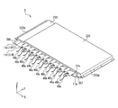
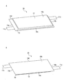
- FIG. 1A is a perspective view of the laminate cell according to the first embodiment of the present invention viewed from the upper surface side
- FIG. 1B is a perspective view viewed from the lower surface side thereof.
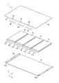
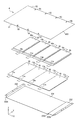
- FIG. 2 is an exploded perspective view of the battery module according to the first embodiment of the present invention.
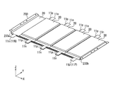
- FIG. 3 is a perspective view showing one step of the method for manufacturing the battery module according to the first embodiment of the present invention.
- FIG. 4 is a perspective view showing the next step of the method for manufacturing the battery module according to Embodiment 1 of the present invention.
- FIG. 5 is a perspective view showing the next step of the method for manufacturing the battery module according to Embodiment 1 of the present invention.
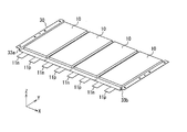
- FIG. 6 is a perspective view of the battery module according to the first embodiment of the present invention.
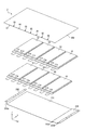
- FIG. 7 is an exploded perspective view of the battery module according to the second embodiment of the present invention.
- FIG. 8 is a perspective view showing a step of the method for manufacturing the battery module according to the second embodiment of the present invention.
- FIG. 9 is a perspective view showing the next step of the method for manufacturing the battery module according to Embodiment 2 of the present invention.
- FIG. 10 is a perspective view showing the next step of the method for manufacturing the battery module according to Embodiment 2 of the present invention.
- FIG. 11 is a perspective view of the battery module according to the second embodiment of the present invention.
- FIG. 12 is an exploded perspective view of the composite battery module according to the third embodiment of the present invention.
- FIG. 13 is a perspective view showing one step of the method for manufacturing the composite battery module according to the third embodiment of the present invention.
- FIG. 14A is a perspective view of the laminate cell according to the fourth embodiment of the present invention viewed from the upper surface side
- FIG. 14B is a perspective view thereof viewed from the lower surface side.
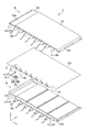
- FIG. 15 is an exploded perspective view of a battery module according to Embodiment 4 of the present invention.
- FIG. 16 is a perspective view showing one step of the method for manufacturing the battery module according to the fourth embodiment of the present invention.
- FIG. 17 is a perspective view showing the next step of the method for manufacturing the battery module according to Embodiment 4 of the present invention.
- FIG. 18 is a perspective view showing the next step of the method for manufacturing the battery module according to Embodiment 4 of the present invention.
- FIG. 19 is a perspective view of a battery module according to Embodiment 4 of the present invention.
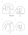
- FIG. 20A is a plan view of a locking portion including a substantially “L”-shaped cutout.
- FIG. 20B is a plan view of a locking portion formed of a substantially “J”-shaped notch.
- FIG. 20C is a plan view of a locking portion formed of a substantially “I”-shaped notch.
- FIG. 20D is a plan view of a locking portion formed of a through hole.
- the locking portion may be provided at a position facing the conductive path to which the voltage monitoring wiring is connected. According to this aspect, the possibility that the wiring is erroneously locked to the locking portion different from the locking portion to be locked is reduced. This is advantageous in reducing the possibility of making an erroneous connection in which the wiring is connected to a terminal different from the terminal to be originally connected when the wiring is connected to the terminal on the circuit board.
- the locking portion may be a notch or a through hole. Such an aspect is advantageous in forming the locking portion for locking the wiring on the insulating sheet with a simple structure. Further, since such a locking portion can be easily formed on the insulating sheet by punching or the like, it is advantageous in facilitating the manufacture of the battery module.
- the plurality of laminate cells may be laminated in a single layer structure on the tray so that the plurality of laminate cells are arranged in a line along the first direction.
- Such an embodiment is advantageous in simplifying the structure of the battery module and facilitating the manufacture of the battery module because the laminated cells are easily arranged. Further, such an aspect is also advantageous in reducing the thickness of the battery module.
- the positive electrode tab and the negative electrode tab connected to the power generating element may be derived from the sides of the substantially rectangular laminate cell.
- the positive electrode tab and the negative electrode tab may protrude from the tray when viewed in a direction perpendicular to the tray. Such a mode facilitates the work of connecting the positive electrode tab and the negative electrode tab. Therefore, the manufacture of the battery module is facilitated.
- the layer may be the first layer.
- the plurality of laminate cells may be stacked on the tray in a two-layer structure including the first layer and the second layer.
- the positive electrode tab and the negative electrode tab connected to the power generation element may be led out from the sides of the substantially rectangular laminate cell.
- the at least two laminate cells forming the first layer may be arranged in a row along the first direction at a constant pitch so that the sides thereof are along a straight line.
- the positive electrode tab of the laminate cell forming the first layer and the negative electrode tab of the laminate cell forming the second layer are the first layer and the first layer.
- the battery module of this aspect can be manufactured by stacking a plurality of laminate cells on a tray in a two-layer structure and then sequentially connecting pairs of tabs having different polarities facing each other in the stacking direction. Therefore, it is easy to manufacture the battery module.
- the positive electrode tab and the negative electrode tab may be derived from a common side of the laminate cell.
- the at least two laminate cells forming the first layer may be arranged so that the positive electrode tabs and the negative electrode tabs are alternately arranged in the first direction. According to this aspect, it is possible to configure the battery module of the present invention in which a plurality of laminate cells are laminated in a two-layer structure by using the laminate cells derived from the side where the positive electrode tab and the negative electrode tab are common.
- the positive electrode tab may be derived from the first side of the laminate cell
- the negative electrode tab may be derived from the second side of the laminate cell parallel to the first side.
- the at least two laminate cells forming the first layer may be arranged so that the first side and the second side thereof are respectively aligned.
- the battery cell of the present invention in which a plurality of laminated cells are laminated in a two-layer structure can be configured by using the laminated cells in which the positive electrode tab and the negative electrode tab are led out from different sides in opposite directions. ..
- the first layer may be composed of N of the laminated cells.
- the second layer may be composed of N-1 to N+1 laminated cells. According to this aspect, it is possible to connect all the cells forming the first layer and all the cells forming the second layer in series only by sequentially connecting the pairs of tabs having different polarities facing each other in the stacking direction. it can.
- the second layer may include at least two laminate cells.
- the at least two laminate cells forming the second layer are arranged in the first direction at the same pitch as the pitch so that the sides from which the positive electrode tab and the negative electrode tab are derived are along a straight line. They may be arranged in a line along. According to such an aspect, it is possible to provide a battery module of the present invention that is easy to manufacture and that includes the first layer including at least two laminated cells and the second layer including at least two laminated cells.
- the amount of positional deviation of the laminate cell forming the second layer in the first direction with respect to the laminate cell forming the first layer may be half the pitch.
- Such a mode facilitates the tabs of different polarities to face each other in the stacking direction. Therefore, it becomes easier to manufacture the battery module of the present invention in which a plurality of laminated cells are laminated in a two-layer structure.
- the positive electrode tab and the negative electrode tab may protrude from the tray along a second direction that is perpendicular to the first direction and perpendicular to the stacking direction. Such a mode facilitates the work of connecting the tabs of different polarities facing each other in the stacking direction. Therefore, the manufacturing of the battery module becomes easier.
- the laminate cell may be arranged only on one side of the insulating sheet on which the plurality of locking portions are formed. Such an aspect is advantageous in simplifying the structure of the battery module.
- the plurality of laminate cells may have either a single-layer structure or a two-layer structure.
- the laminate cells may be arranged on both sides of the insulating sheet on which the plurality of locking portions are formed. Such an aspect is advantageous in increasing the battery capacity of the battery module.
- the plurality of laminated cells may have either a single-layer structure or a two-layer structure.
- the voltage monitoring wiring connected to the conductive path may be locked to a locking portion formed on the insulating sheet. According to this aspect, all the wirings on both sides of the insulating sheet are locked by the locking portions formed on the common insulating sheet. This prevents the number of insulating sheets from increasing, which is advantageous in simplifying the structure of the battery module and facilitating the manufacture of the battery module.
- the voltage monitoring wiring connected to the conductive path may be led out to the same side with respect to the insulating sheet. According to this aspect, the wiring can be easily handled. For example, it becomes easy to connect all the wirings to the terminals provided on a single wiring board.
- the color may be different from that of the voltage monitoring wiring connected to the conductive path. According to this aspect, it is possible to reduce the possibility of erroneous connection in which the wiring is connected to a terminal different from the terminal to which the wiring should be originally connected, by a simple method.
- FIG. 1A is a perspective view of a laminate cell (hereinafter, simply referred to as “cell”) 10 that constitutes a battery module 1 (see FIG. 6 described later) according to the first embodiment of the present invention as viewed from the upper side, and FIG. It is the perspective view seen from the lower surface side.
- the cell 10 has a substantially rectangular shape in plan view, and has a thin plate shape having a thickness smaller than the vertical and horizontal dimensions of the substantially rectangular shape.
- a thin plate-shaped power generating element (not shown) having a substantially rectangular plan view shape is enclosed together with an electrolytic solution in an exterior made of a laminate sheet 13.
- the power generation element includes a positive electrode in which a positive electrode mixture layer containing a positive electrode active material is applied and formed on both sides of a predetermined region of a positive electrode current collector, and a negative electrode mixture layer containing a negative electrode active material on both sides of a predetermined region of a negative electrode current collector.
- a positive electrode in which a positive electrode mixture layer containing a positive electrode active material is applied and formed on both sides of a predetermined region of a positive electrode current collector, and a negative electrode mixture layer containing a negative electrode active material on both sides of a predetermined region of a negative electrode current collector.
- the type of battery is not particularly limited, but a secondary battery, particularly a lithium ion secondary battery is preferable.
- the laminate sheet 13 is thinner and more flexible than the power generating element.
- the laminate sheet 13 may be, for example, a multi-layer sheet in which a heat-fusible resin layer (for example, a modified polyolefin layer) is laminated on the surface of the base layer made of aluminum or the like facing the power generating element.
- Two rectangular laminated sheets 13 are arranged with the power generation element sandwiched therebetween, and are laminated outside the power generation element and sealed by a heat sealing method or the like.
- the seal areas 14a, 14b, 14c and 14d where the two laminated sheets 13 are sealed are along the four sides of the substantially rectangular cell 10.
- the seal regions 14a and 14b are along the short side of the cell 10, and the seal regions 14c and 14d are along the long side of the cell 10. All the seal areas 14a to 14d are on a common plane.
- An emboss 12 having a substantially rectangular shape in plan view corresponding to the power generating element projects to one side with respect to the seal regions 14a to 14d
- the direction orthogonal to the plane including the seal areas 14a to 14d is called the "thickness direction" of the cell 10.
- the first main surface 15a is the top surface of the embossing 12 (see FIG. 1A)
- the second main surface 15b is the surface opposite to the embossing 12 (see FIG. 1B).
- the two main surfaces 15a and 15b are parallel to each other and perpendicular to the thickness direction of the cell 10.
- the positive electrode tab 11p and the negative electrode tab 11n are led out from the seal region 14a (or the first short side along which the seal region 14a extends).
- the positive electrode tab 11p and the negative electrode tab 11n have a strip shape, and are arranged in a direction orthogonal to the longitudinal direction of the seal region 14a (that is, in a direction parallel to the pair of seal regions 14c and 14d connected to both ends of the seal region 14a). Running along.
- the positive electrode tab 11p is made of, for example, a thin aluminum plate, and is electrically connected to a plurality of positive electrode current collectors (not shown) that form a power generation element.
- the negative electrode tab 11n is made of, for example, a thin nickel plate or the like, and is electrically connected to a plurality of negative electrode current collectors (not shown) that constitute the power generation element.
- the seal region 14a along the side where the positive electrode tab 11p and the negative electrode tab 11n are led out is referred to as a "terrace portion”.
- the seal areas 14c and 14d connected to both ends of the terrace portion 14a are referred to as "ear portions".
- the first ear portion 14c and the second ear portion 14d extend along a side perpendicular to the side of the cell 10 along which the terrace portion 14a extends.
- FIG. 2 is an exploded perspective view of the battery module 1 according to the first embodiment.
- the battery module 1 includes a tray 30, four cells 10, three connecting members 45, three voltage monitoring wires (wires) 40 (not shown in FIG. 2, see FIG. 5 described later), The insulating sheet 50 is included.
- the four cells 10 are the same.
- the four cells 10 are mounted on the tray 30 in a one-layer (single-layer) structure.
- an XYZ orthogonal coordinate system as shown is set.
- the Z axis coincides with the thickness direction of the cell 10.
- the direction parallel to the XY plane is called “horizontal direction”
- the direction parallel to the Z axis is called “vertical direction”.
- the dimension in the Z-axis direction is called "thickness" or "height”. Note that “horizontal” and “upper and lower” do not mean the attitude of the battery module 1 during use.
- the tray 30 is made of a substantially rectangular plate material as a whole.
- the tray 30 includes a bottom portion 31, a first wall 33a, and a second wall 33b.
- the bottom portion 31 is a rectangular flat surface parallel to the XY plane.
- the length of the bottom portion 31 (dimension in the X-axis direction) is approximately the same as the sum of the dimensions in the short side direction of the four cells 10.
- the width (dimension in the Y-axis direction) of the bottom portion 31 is substantially the same as the dimension in the long side direction (not including the tabs 11p and 11n) of the cell 10.
- First and second walls 33a and 33b are provided on two sides of the bottom portion 31 parallel to the Y axis.
- Each of the first and second walls 33a and 33b is a rectangular flat surface parallel to the YZ plane.
- the height (dimension in the Z-axis direction) of the first and second walls 33a and 33b is substantially the same as or slightly larger than the thickness of the cell 10.
- the tray 30 is made of a plate material having a mechanical strength sufficient to support the total load of the cells 10 placed on the tray 30.
- the material of the tray 30 is not limited, but a metal such as aluminum or stainless steel, a hard resin material such as polyester, polypropylene, or hard vinyl chloride, a fiber reinforced plastic, or the like can be used.
- FIG. 3 First, as shown in FIG. 3, four cells 10 are placed on the bottom 31 (see FIG. 2) of the tray 30 with their embosses 12 (see FIG. 1A) facing upward.
- an insulating sheet (not shown) between the tray 30 and the four cells 10.
- the method of fixing the four cells to the tray 30 is not limited, but, for example, a double-sided adhesive tape or an adhesive can be used.
- the four cells 10 are arranged in a row at a constant pitch along the longitudinal direction (X-axis direction) of the tray 30. In this example, the arrangement pitch of the cells 10 in the X-axis direction is substantially the same as the dimension of the cells 10 in the short side direction.
- the terraces 14a of the four cells 10 (see FIG.
- the ears 14c and 14d of the four cells 10 are parallel to the Y axis.
- the positive electrode tabs 11p and the negative electrode tabs 11n of the four cells 10 are alternately arranged in the X-axis direction.
- the tabs 11p and 11n project from the tray 30 toward the same side along the Y-axis direction.
- the four cells 10 are arranged in the recess having the bottom portion 31 from the first wall 33a to the second wall 33b as the bottom surface in the X-axis direction with substantially no space.
- the first main surface 15a (see FIG. 1A) and the second main surface 15b (see FIG. 1B) of the four cells 10 are respectively along one plane parallel to the XY plane.
- the positive electrode tab 11p and the negative electrode tab 11n are electrically connected between the cells 10 adjacent to each other in the X-axis direction. That is, the positive electrode tab 11p of a certain cell 10 and the negative electrode tab 11n of another cell 10 adjacent to this cell 10 in the X-axis direction are connected.
- Four cells 10 arranged in the X-axis direction are connected in series.
- the method of connecting the positive electrode tab 11p and the negative electrode tab 11n is not limited, and in the first embodiment, the strip-shaped (that is, elongated rectangular) connection member 45 is bridged between the positive electrode tab 11p and the negative electrode tab 11n. A conductive path is formed in which the positive electrode tab 11p, the connecting member 45, and the negative electrode tab 11n are sequentially connected.
- the method of connecting the connection member 45 and the tabs 11n and 11p is not limited, and any method such as ultrasonic welding, resistance welding, laser welding, caulking, or bonding with a conductive adhesive can be used.
- the material of the connecting member 45 can be selected according to the material of the tabs 11n and 11p, the method of connecting the connecting member 45 and the tabs 11n and 11p, and the like.
- As the connecting member 45 for example, a copper/aluminum two-layer laminated clad material can be used. Since the tabs 11p and 11n protrude from the tray 30 and are arranged in a line in the X-axis direction on the same plane, it is easy to sequentially connect the adjacent tabs 11p and 11n via the connecting member 45.
- the wiring (wire) 40 is connected to each connecting member 45.
- the wiring 40 is used to monitor the voltage of each of the four cells 10 connected in series.
- the connection method between the connection member 45 and the wiring 40 is not limited, and any method such as soldering or caulking can be used.
- the positive electrode tab 11p and the negative electrode tab 11n are connected by the connecting member 45 and then the wiring 40 is connected to the connecting member 45, but the present invention is not limited to this.
- the connection member 45 to which the wiring 40 is connected in advance may be connected to the positive electrode tab 11p and the negative electrode tab 11n.
- the insulating sheet 50 is placed on the four cells 10.
- the insulating sheet 50 is a sheet having a desired electrical insulation property.
- the insulating sheet 50 has a shape-retaining property that is not substantially deformed by gravity, flexibility that is relatively easily elastically deformable when an external force is applied, and flame retardancy. preferable.
- a resin material is generally used.
- “Sun Morphy” (registered trademark) manufactured by Sun Delta Co., Ltd. can be used.
- the method for fixing the insulating sheet 50 to the cell 10 is not limited and, for example, a double-sided adhesive tape or an adhesive can be used.
- the insulating sheet 50 is cut into a substantially rectangular shape having a size that can substantially cover the four cells 10. More specifically, the length (dimension in the X-axis direction) of the insulating sheet 50 is substantially the same as the sum of the dimensions in the short side direction of the four cells 10, and the width (dimension in the Y-axis direction) of the insulating sheet 50 is It is substantially the same as the dimension of the cell 10 in the long side direction (including the tabs 11p and 11n). Three notches 55 (see FIG. 2) are provided on the side (long side) 51 of the insulating sheet 50 on the same side as the tabs 11p and 11n.
- the cutout 55 is provided at a position where the connecting member 45 and the cutout 55 face each other in the vertical direction when the insulating sheet 50 is placed on the four cells 10.
- the plan view shape of the notch 55 viewed along the Z axis is substantially “L” (see FIG. 20A). Each notch 55 is open to the side 51 of the insulating sheet 50.
- each wiring 40 is locked in the notch 55 located above the connecting member 45 to which the wiring 40 is connected.
- the wiring 40 is led out upward from the notch 55.
- a flat plate (not shown) may be attached between the first wall 33a and the second wall 33b so as to overlap the insulating sheet 50.
- the four cells 10 are surrounded by the tray 30 and this flat plate.
- the flat plate is made of, for example, but not limited to, the same material as the tray 30.
- the insulating sheet 50 insulates the four cells 10 from this flat plate.
- a circuit board (not shown) provided with a protection circuit can be installed, for example, on the upper surface (the surface opposite to the cell 10) of this flat plate.
- the same number of terminals as the wirings 40 are provided on the circuit board.
- the wiring 40 is connected to the corresponding terminal.
- the tab closest to the first wall 33a (negative electrode tab 11n in this embodiment) and the tab closest to the second wall 33b (positive electrode tab 11p in this embodiment). ) Is not connected to the connection member 45.
- the negative electrode tab 11n closest to the first wall 33a becomes the negative electrode terminal 11N of the battery module 1
- the positive electrode tab 11p closest to the second wall 33b becomes the positive electrode terminal 11P of the battery module 1.
- Four cells 10 are connected in series between the negative electrode terminal 11N and the positive electrode terminal 11P. By using the negative electrode terminal 11N and the positive electrode terminal 11P as input/output terminals, the battery module 1 including four cells can be charged/discharged.
- the insulating sheet 50 is provided with the notch 55 for locking the wiring 40. Therefore, the notch 55 can be arranged near the connecting member 45. Unlike the conventional case, since it is not necessary to provide the notch 55 on the circuit board, even if the number of the cells 10 configuring the battery module 1 is large, the circuit board is larger than the area required for mounting the components. There is no need to turn it into.
- the insulating sheet 50 extends above the connecting member 45 (see FIG. 6). When viewed from above, the connecting member 45 may be invisible because it is covered with the insulating sheet 50.
- the cutouts 55 are provided at a position almost directly above the connection member 45 so as to correspond to the connection member 45 in a one-to-one manner.
- the wiring 40 is locked to the nearest notch 55 as shown in FIG. It is unlikely that the wiring 40 is locked in the notch 55 different from the notch 55 that should be originally locked.
- the connection member 45 to which the wiring 40 is connected is determined depending on which connection member 45 the wiring 40 is connected to even if the connecting member 45 cannot be visually recognized. It can be easily understood by the position of the notch 55. Therefore, when the wiring 40 is subsequently connected to the terminal on the circuit board, the possibility of erroneous connection of connecting the wiring 40 to a terminal different from the terminal to be originally connected is low.
- FIG. 6 when a flat plate (not shown) attached between the first wall 33a and the second wall 33b so as to cover the four cells 10 is made of a conductive material such as metal, the cells 10 are insulated from the flat plate. In order to do so, the insulating sheet 50 is essential. The notch 55 is provided on the insulating sheet 50, not on the circuit board. Even though the cutout 55 is provided in a member other than the circuit board, the number of members constituting the battery module 1 does not increase, and the manufacturing process of the battery module 1 does not increase.
- the battery module 1 of the first embodiment four cells 10 are placed on the tray 30 along the X axis.
- the tabs 11p and 11n to which the connecting member 45 is connected are arranged along the X axis.
- the step of placing the cell 10 on the tray 30 and the step of connecting the tabs 11p and 11n of different polarities that are adjacent to each other in the X-axis direction through the connecting member 45 are both simple and easy to automate by a machine. Is.
- the battery module 1 of Embodiment 1 is easier to manufacture than a conventional battery module in which a plurality of cells are stacked in the thickness direction. Therefore, the battery module 1 can be manufactured at low cost.
- the insulating sheet 50 a single sheet having a relatively large area corresponding to the four cells 10 can be used.
- an insulating sheet (not shown) is interposed between the tray 30 and the cell 10
- a single sheet having a relatively large area can be used as the insulating sheet.
- the application of the double-sided adhesive tape or the application of the adhesive for fixing the cells 10 and these insulating sheets can be continuously performed in a relatively wide area corresponding to the four cells 10. It is not necessary to install an insulating sheet having a small area corresponding to one cell 10 for each cell 10, and it is not necessary to attach a double-sided adhesive tape or apply an adhesive to each cell 10. From this point as well, the battery module 1 of Embodiment 1 is easy to manufacture.
- the tray 30 functions as a jig for positioning and holding the four cells 10 at predetermined positions in the manufacturing process of the battery module 1. Further, the tray 30 functions as a housing of the battery module 1 that holds and accommodates the four cells 10 after the battery module 1 is completed. That is, in the manufacturing process of the battery module 1, a dedicated jig for positioning the cells 10 is not necessary. Further, it is not necessary to separate the four cells 10 connected in series from the tray 30 and store them in another housing. From these points as well, the battery module 1 of Embodiment 1 is easy to manufacture and can be manufactured at low cost.
- the four cells 10 are arranged on the tray 30 in a single-layer (single-layer) structure, so that the dimension in the thickness direction (that is, the dimension in the Z-axis direction) is overall. It is a panel-like product that is small and has a relatively large horizontal dimension (that is, X-axis direction dimension and Y-axis direction dimension).
- the battery module 1 is attached to, for example, a wall or a ceiling, the amount of protrusion is small and a feeling of pressure is not felt. Further, the battery module 1 can be inserted and arranged in a slight gap.
- the notch 55 is provided in the insulating sheet 50 provided on the surface of the four cells 10 opposite to the tray 30, but the present invention is not limited to this.
- the cutout 55 similar to the insulating sheet 50 may be provided in the insulating sheet interposed between the tray 30 and the four cells 10. This configuration is advantageous, for example, when the circuit board is installed on the lower surface of the tray 30 (the surface opposite to the cell 10).
- FIG. 7 is an exploded perspective view of the battery module 2 of the second embodiment.
- the battery module 2 is different from the battery module 1 of Embodiment 1 in which the cell 10 has a two-layer structure and is mounted on the tray 230, and the cell 10 has a single-layer structure and is mounted on the tray 30.
- the second embodiment will be described focusing on the differences from the first embodiment.
- the battery module 2 includes eight cells 10. Eight cells 10 are the same. Of the eight cells 10, four cells 10 on the tray 230 side form a lower layer, and the remaining four cells 10 form an upper layer. The eight cells 10 are stacked on the tray 230 in a two-layer structure including a lower layer and an upper layer. The insulating sheet 250 in which the notch 55 is formed is placed on the upper cell 10.
- the tray 230 includes a first bottom portion 231 that occupies most of the lengthwise direction (X-axis direction) and a second bottom portion 232 that is adjacent to the first bottom portion 231 in the X-axis direction.
- the first bottom portion 231 and the second bottom portion 232 are both flat surfaces parallel to the XY plane.
- the second bottom portion 232 is displaced upward with respect to the first bottom portion 231 in a stepwise manner.
- the length (dimension in the X-axis direction) of the first bottom portion 231 is substantially the same as the sum of the dimensions in the short side direction of the four cells 10 forming the lower layer.
- the length (dimension in the X-axis direction) of the second bottom portion 232 is approximately half the arrangement pitch of the cells 10 in the X-axis direction (details will be described later).
- the widths (dimensions in the Y-axis direction) of the first bottom portion 231 and the second bottom portion 232 are substantially the same as the dimensions in the long side direction (not including the tabs 11p and 11n) of the cell 10.
- the vertical distance between the first bottom portion 231 and the second bottom portion 232 is substantially the same as the thickness of the cell 10.
- a first wall 233a is provided at an end of the first bottom portion 231 opposite to the second bottom portion 232.
- a second wall 233b is provided at the end of the second bottom portion 232 opposite to the first bottom portion 232.
- An intermediate wall 233c is provided at the boundary between the first bottom portion 231 and the second bottom portion 232 so as to connect them.
- Each of the walls 233a, 233b, 233c is a rectangular flat surface parallel to the YZ plane.
- the height (dimension in the Z-axis direction) of the first wall 233a is substantially the same as twice the thickness of the cell 10 or slightly larger than this.
- the height (dimension in the Z-axis direction) of the second wall 233b is approximately the same as or slightly larger than the thickness of the cell 10.
- the four cells 10 forming the lower layer are placed on the first bottom portion 231 (see FIG. 7) of the tray 230 with the embosses 12 (see FIG. 1A) facing upward. Place.
- an insulating sheet (not shown) may be interposed between the tray 230 (particularly the first wall 233a, the first bottom portion 231, and the intermediate wall 233c) and the four cells 10. Is preferred.
- the method of fixing the four cells to the tray 230 is not limited, but, for example, a double-sided adhesive tape or an adhesive can be used.
- the four cells 10 are arranged in a row at a constant pitch along the longitudinal direction (X-axis direction) of the tray 230.
- the arrangement pitch of the cells 10 in the X-axis direction is substantially the same as the dimension of the cells 10 in the short side direction.
- the terraces 14a of the four cells 10 (see FIG. 1A. or the first short side along which the terraces 14a extend) are aligned along the X-axis direction.
- the ears 14c and 14d of the four cells 10 (or the long sides of the cells 10) are parallel to the Y axis.
- the positive electrode tabs 11p and the negative electrode tabs 11n of the four cells 10 are alternately arranged in the X-axis direction.
- the tabs 11p and 11n protrude from the tray 230 toward the same side along the Y-axis direction.
- the four cells 10 are arranged in the recess having the first bottom portion 231 from the first wall 233a to the intermediate wall 233c as the bottom surface in the X-axis direction with almost no gap.
- the second major surfaces 15b (see FIG. 1B) of the four cells 10 are along a plane parallel to the XY plane.
- the first main surface 15a (see FIG. 1A) of the four cells 10 and the second bottom portion 232 are along a plane parallel to the XY plane.
- FIG. 9 another four cells 10 constituting the upper layer are placed on the four cells 10 in the lower layer with their embosses 12 facing upward. It is preferable to interpose an insulating sheet (not shown) between the lower four cells 10 and the tray 230 (in particular, the second bottom portion 232 and the second wall 233b) and the upper four cells 10. In addition, when the tray 230 has an insulating property, an insulating sheet is not required between the tray 230 and the upper cell 10.
- the method of fixing the upper cell 10 is not limited, but, for example, a double-sided adhesive tape or an adhesive can be used.
- the four cells 10 in the upper layer are arranged in a row at a constant pitch along the X-axis direction.
- the arrangement pitch of the cells 10 in the upper layer is the same as the arrangement pitch of the cells 10 in the lower layer.
- the terraces 14a (see FIG. 1A. or the first short side along which the terraces 14a extend) of the four cells 10 in the upper layer are aligned along the X-axis direction.
- the ears 14c and 14d of the four cells 10 (or the long sides of the cells 10) are parallel to the Y axis.
- the positive electrode tabs 11p and the negative electrode tabs 11n of the four cells 10 in the upper layer are alternately arranged in the X-axis direction.
- the tabs 11p and 11n of the four cells 10 in the upper layer protrude from the tray 230 toward the same side as the tabs 11p and 11n of the four cells 10 in the lower layer along the Y-axis direction.
- the four cells 10 in the upper layer are displaced from the four cells 10 in the lower layer by half the arrangement pitch in the X-axis direction toward the second wall 233b.
- the positive electrode tab 11p of the lower layer cell 10 and the negative electrode tab 11n of the upper layer cell 10 vertically face each other, and the negative electrode tab 11n of the lower layer cell 10 and the positive electrode tab 11p of the upper layer cell 10 vertically move. Opposite the direction.
- the positive electrode tab 11p and the negative electrode tab 11n facing each other in the vertical direction are electrically connected.
- a conductive path is formed between the positive electrode tab 11p and the negative electrode tab 11n.
- the tabs 11p and 11n of the four cells 10 in the upper layer are bent in two steps in a stepwise manner so that the tip portions thereof are located downward (second wall 233b) for easy connection. (Except for the positive electrode tab 11p closest to).
- the method of connecting the positive electrode tab 11p and the negative electrode tab 11n is not limited, but any method such as ultrasonic welding, resistance welding, laser welding, caulking, or bonding with a conductive adhesive can be used. Since the pair of tabs 11p and 11n to be connected protrudes from the tray 230 and are arranged in a line in the X-axis direction, the work of sequentially connecting the pair of tabs 11p and 11n is easy.
- a wiring (wire) 40 for monitoring the voltage of each cell 10 is connected to each of the connection parts where the positive electrode tab 11p and the negative electrode tab 11n are connected.
- the connection method between the tabs 11p and 11n and the wiring 40 is not limited, and any method such as soldering or caulking can be used.
- the positive electrode tab 11p and the negative electrode tab 11n are connected and then the wiring 40 is connected to these tabs 11p and 11n, but the present invention is not limited to this.
- the positive electrode tab 11p, the negative electrode tab 11n, and the wiring 40 may be simultaneously connected.
- the insulating sheet 250 is placed on the upper four cells 10.
- the material and fixing method of the insulating sheet 250 may be the same as in the first embodiment.
- the insulating sheet 250 is cut into a substantially rectangular shape that is large enough to cover at least the four upper cells 10. More specifically, the length (dimension in the X-axis direction) of the insulating sheet 250 is substantially the same as the distance between the first wall 233a and the second wall 233b, and the width (dimension in the Y-axis direction) of the insulating sheet 250 is It is substantially the same as the dimension of the cell 10 in the long side direction (including the tabs 11p and 11n). Seven notches 55 (see FIG. 7) are provided on the side (long side) 51 of the insulating sheet 250 on the same side as the tabs 11p and 11n. The cutout 55 is provided at a position where the connection portion between the positive electrode tab 11p and the negative electrode tab 11n and the cutout 55 face each other in the vertical direction when the insulating sheet 250 is placed on the upper layer cell 10. ..
- each wiring 40 is locked in the notch 55 located above the connecting portion of the tabs 11p and 11n to which the wiring 40 is connected.
- the wiring 40 is led out upward from the notch 55.
- a flat plate (not shown) may be attached between the first wall 233a and the second wall 233b so as to overlap the insulating sheet 250.
- the eight cells 10 are surrounded by the tray 230 and this flat plate.
- the flat plate is made of, for example, but not limited to, the same material as the tray 230.
- the insulating sheet 250 insulates the upper cell 10 from this flat plate.
- a circuit board (not shown) provided with a protection circuit can be installed, for example, on the upper surface (the surface opposite to the cell 10) of this flat plate.
- the same number of terminals as the wirings 40 are provided on the circuit board.
- the wiring 40 is connected to the corresponding terminal.
- the first wall of the tabs 11p and 11n of the four cells 10 in the lower layer is There is no tab vertically opposed to the tab closest to 233a (the negative electrode tab 11n in this embodiment), and the tab closest to the second wall 233b among the tabs 11p and 11n of the upper cell 10 ( In this embodiment, there is no tab vertically facing the positive electrode tab 11p) (see FIG. 10).
- the lower layer negative electrode tab 11n closest to the first wall 233a becomes the negative electrode terminal 11N of the battery module 2
- the upper layer positive electrode tab 11p closest to the second wall 233b becomes the positive electrode terminal 11P of the battery module 2.
- the battery module 2 including eight cells can be charged/discharged.
- the insulating sheet 250 is also provided with the notch 55 for locking the wiring 40. Therefore, the notch 55 can be arranged near the connecting member 45. Unlike the conventional case, since it is not necessary to provide the notch 55 on the circuit board, even if the number of cells 10 configuring the battery module 2 is large, the circuit board is larger than the area required to mount the components. There is no need to turn it into.
- the insulating sheet 250 extends to above the connecting portion between the positive electrode tab 11p and the negative electrode tab 11n (see FIG. 11). When viewed from above, the connection portion may be invisible because it is covered with the insulating sheet 250.
- the cutouts 55 are provided at a position almost directly above the connecting portion, one-to-one corresponding to the connecting portion. After placing the insulating sheet 250 on the cell 10, the wiring 40 is locked to the nearest notch 55 as shown in FIG. It is unlikely that the wiring 40 is locked in the notch 55 different from the notch 55 that should be originally locked. After the wiring 40 is locked in the notch 55, even if the connecting member 45 cannot be visually recognized, the connection portion to which the wiring 40 is connected is determined by the notch in which the wiring 40 is locked. It can be easily understood by the position of 55. Therefore, when the wiring 40 is subsequently connected to the terminal on the circuit board, the possibility of erroneous connection of connecting the wiring 40 to a terminal different from the terminal to be originally connected is low.
- the battery module 2 of the second embodiment eight cells 10 are placed on the tray 230 in a two-layer structure.
- the positive electrode tab 11p and the negative electrode tab 11n to be connected face each other in the vertical direction, and a pair of the tabs 11p and 11n are arranged along the X axis.
- Both the step of placing the cell 10 on the tray 230 and the step of connecting the tabs 11p and 11n of different polarities to each other are simple, and automation by a machine is easy.
- the battery module 2 of Embodiment 2 is easier to manufacture than a conventional battery module in which a plurality of cells are stacked in the thickness direction. Therefore, the battery module 2 can be manufactured at low cost.
- the positive electrode tab 11p and the negative electrode tab 11n face each other in the vertical direction. Then, the positive electrode tab 11p and the negative electrode tab 11n may be brought close to each other and electrically connected.
- the connection member 45 used in the first embodiment is not necessary to connect the positive electrode tab 11p and the negative electrode tab 11n. This is advantageous in the following points. First, the number of parts and the number of manufacturing steps can be reduced, so that the battery module 2 can be manufactured at low cost.
- the positive electrode tab 11p and the negative electrode tab 11n may be connected via a member different from these.
- the second embodiment is the same as the first embodiment except the above.
- the description of the first embodiment is similarly applied to the second embodiment.
- FIG. 12 is an exploded perspective view of the composite battery module 3 according to the third embodiment of the present invention.
- the composite battery module 3 includes two battery modules 2a and 2b and an insulating sheet 350.
- the battery modules 2a and 2b correspond to the battery module of Embodiment 2 (see FIG. 10) before the insulating sheet 250 is placed.
- the battery module 2a and the battery module 2b are the same.
- the wiring 40 of the lower battery module 2a is attached with a subscript “a”
- the wiring 40 of the upper battery module 2b is attached with a subscript “b”. is there.
- the insulating sheet 350 is the insulating sheet 250 of Embodiment 2 (see FIG. 7) provided with seven notch pairs 355 and notches 357.
- the notch pair 355 includes two notches 355a and 355b that are symmetrically arranged.
- the plan view shape of the notches 355a and 355b viewed along the Z axis is substantially “L” like the notch 55 (see FIG. 20A).
- the seven notch pairs 355 are provided along the side 51 so that the notch pairs 355 and the notches 55 are alternately arranged.
- the cutout 357 is provided at one end of the side 51.
- the insulating sheet 350 is fixed on the four cells 10 in the upper layer of the lower battery module 2a.
- the lower battery module 2a is covered with the upper battery module 2b with the insulating sheet 350 interposed therebetween.
- the tabs 11p and 11n of the battery module 2a and the tabs 11p and 11n of the battery module 2b project toward the same side.
- the first wall 233a of the battery module 2a is connected to the second wall 233b of the battery module 2b, and the second wall 233b of the battery module 2a is connected to the first wall 233a of the battery module 2b.
- FIG. 13 shows this state.
- each wiring 40a of the lower battery module 2a is locked in the notch 55 located above the connection portion of the tabs 11p and 11n to which the wiring 40a is connected.
- the wiring 40a is led out upward from the cutout 55.
- Each wiring 40b of the upper battery module 2b is locked to the notch pair 355 located below the connection portion of the tabs 11p and 11n to which the wiring 40b is connected. More specifically, the wiring 40b is first locked in the cutout 355a so as to traverse the insulating sheet 350 from the top to the bottom, and then the wiring 40b is cut out so as to traverse the insulation sheet 350 from the bottom to the top. Lock on. The wiring 40b is led out upward from the cutout 355b.
- the seven wirings 40a and the seven wirings 40b are arranged alternately with the wirings 40a and 40b and are locked to the seven notches 55 and the seven notch pairs 355, respectively. .. All the wirings 40a and 40b are led out toward the upper side with respect to the insulating sheet 350.
- the circuit board (not shown) provided with the protection circuit can be installed, for example, on the upper surface (the surface opposite to the cell 10) of the tray 230 of the upper battery module 2b.
- the same number of terminals as the wirings 40a and 40b are provided on the circuit board.
- the wirings 40a and 40b are connected to the corresponding terminals.
- a total of 14 wirings 40a and 40b are locked in the notches provided in the common insulating sheet 350, but since the wirings 40a and 40b are locked alternately along the side 51, the wiring 40a , 40b are unlikely to be erroneously connected by connecting them to terminals different from the terminals to be originally connected.
- the wiring 40a of the battery module 2a and the wiring 40b of the battery module 2b may have different wiring colors. This is advantageous to further reduce the possibility of misconnection.
- the positive electrode terminal 11P (see FIG. 12) of the lower battery module 2a and the negative electrode terminal 11N (see FIG. 12) of the upper battery module 2b face each other in the vertical direction via the cutout 357 of the insulating sheet 350. These two terminals 11P and 11N are brought close to each other and electrically connected. Eight cells 10 of the lower battery module 2a and eight cells 10 of the upper battery module 2b are connected in series. Using the negative electrode terminal 11N of the lower battery module 2a and the positive electrode terminal 11P of the upper battery module 2b as input/output terminals, it is possible to charge and discharge the composite battery module 3 including 16 cells.
- a battery module (composite battery module) similar to the composite battery module 3 of Embodiment 3 is configured by combining the two battery modules of Embodiment 1 (see FIG. 5) and the insulating sheet having the cutout formed therein. You can also
- FIG. 14A is a perspective view of a laminated cell (hereinafter, simply referred to as “cell”) 20 that constitutes a battery module 4 (see FIG. 19 described later) according to the fourth embodiment of the present invention, viewed from the upper side, and FIG. It is the perspective view seen from the lower surface side.
- the cell 20 is different from the cell 10 of Embodiment 1 (see FIGS. 1A and 1B) with respect to the arrangement of the positive electrode tab 11p and the negative electrode tab 11n. That is, in the cell 20 of Embodiment 4, the positive electrode tab 11p is led out from the seal region (first terrace portion) 14a, and the negative electrode tab 11n is led out from the seal region (second terrace portion) 14b.
- the first and second terraces 14a and 14b are along the first and second short sides of the substantially rectangular cell 20, which are parallel to each other.
- the positive electrode tab 11p is arranged near the first ear portion 14c of the first terrace portion 14a
- the negative electrode tab 11n is arranged near the second ear portion 14d of the second terrace portion 14b.
- the positive electrode tab 11p and the negative electrode tab 11n are arranged at positions near the diagonal of the substantially rectangular cell 20.
- the cell 20 is the same as the cell 10 of the first embodiment except for the above.
- FIG. 15 is an exploded perspective view of the battery module 4 according to the fourth embodiment. Similar to the battery module 2 of the second embodiment, the battery module 4 has eight cells 20 stacked on a tray 230 in a two-layer structure including a lower layer and an upper layer. The eight cells 20 are the same. The insulating sheet 450 in which the notch 55 is formed is placed on the upper cell 10.
- the four cells 20 constituting the lower layer are placed on the first bottom 231 (see FIG. 15) of the tray 230.
- the embossments 12 of the four cells 20 are directed to the lower side (tray 230 side).
- the four cells 20 are arranged in a row at a constant pitch along the longitudinal direction (X-axis direction) of the tray 230.
- the first terrace portions 14a of the four cells 20 are aligned in the X-axis direction, and the second terraces of the four cells 20 are arranged.
- the portion 14b (see FIG.
- the positive electrode tabs 11p of the four cells 20 protrude toward one side of the tray 230 along the Y-axis direction.
- the negative electrode tabs 11n of the four cells 20 protrude toward the opposite side of the tray 230 from the positive electrode tabs 11p along the Y-axis direction.
- the first major surface 15a (see FIG. 14A) of the four cells 20 is along a plane parallel to the XY plane.
- the second main surface 15b (see FIG. 14B) of the four cells 20 and the second bottom portion 232 are along a plane parallel to the XY plane.
- FIG. 17 another four cells 20 constituting the upper layer are placed on the four cells 20 in the lower layer. Unlike the lower four cells 20, the embosses 12 of the upper four cells 20 are directed upward.
- the first terrace portions 14a of the four cells 20 (see FIG. 14A or the first short side along which the first terrace portions 14a extend) are aligned in the X-axis direction, and the second terraces of the four cells 20 are arranged.
- the portion 14b (see FIG. 14A, or the second short side along which the second terrace portion 14b extends) are also aligned along the X-axis direction.
- the positive electrode tabs 11p of the four cells 20 in the upper layer protrude from the tray 230 along the Y-axis direction toward the same side as the negative electrode tabs 11n of the four cells 20 in the lower layer.
- the negative electrode tabs 11n of the four cells 20 in the upper layer protrude from the tray 230 along the Y-axis direction toward the same side as the positive electrode tabs 11p of the four cells 20 in the lower layer.
- the upper four cells 20 are arranged in a line along the X-axis direction at the same pitch as the lower four cells 20. However, the four cells 20 in the upper layer are displaced from the four cells 20 in the lower layer by half the arrangement pitch in the X-axis direction toward the second wall 233b. As a result, the positive electrode tab 11p of the lower layer cell 20 and the negative electrode tab 11n of the upper layer cell 20 vertically face each other, and the negative electrode tab 11n of the lower layer cell 20 and the positive electrode tab 11p of the upper layer cell 20 vertically move. Opposite the direction.
- the positive electrode tab 11p and the negative electrode tab 11n facing each other in the vertical direction are electrically connected.
- a conductive path is formed between the positive electrode tab 11p and the negative electrode tab 11n.
- the surfaces of the lower cell 20 and the upper cell 20 opposite to the respective embosses 12 face each other. Therefore, the positive electrode tab 11p and the negative electrode tab 11n facing each other in the vertical direction are relatively close to each other. This facilitates the connection between the positive electrode tab 11p and the negative electrode tab 11n.
- a wiring (wire) 40 for monitoring the voltage of each cell 20 is connected to each of the connection portions where the positive electrode tab 11p and the negative electrode tab 11n are connected.
- the positive electrode tab 11p and the negative electrode tab 11n are connected and then the wiring 40 is connected to these tabs 11p and 11n, but the present invention is not limited to this.
- the positive electrode tab 11p, the negative electrode tab 11n, and the wiring 40 may be connected at the same time.
- the insulating sheet 450 is placed on the upper four cells 20.
- the insulating sheet 450 is different from the insulating sheet 250 (see FIG. 7) of the second embodiment with respect to the position of the cutout 55.
- three cutouts 55 are provided on the side (first long side) 51 of the insulating sheet 450, and four cutouts 55 are provided on the side (second long side) 52 parallel to the side 51. (See FIG. 15).
- the cutout 55 is provided at a position where the connection portion between the positive electrode tab 11p and the negative electrode tab 11n and the cutout 55 face each other in the vertical direction when the insulating sheet 450 is placed on the upper layer cell 20. ..
- each wiring 40 is locked in the notch 55 located above the connection portion of the tabs 11p and 11n to which the wiring 40 is connected.
- the wiring 40 is led out upward from the notch 55.
- the battery module 4 of Embodiment 4 is obtained. Similar to the second embodiment, a flat plate (not shown) may be attached between the first wall 233a and the second wall 233b.
- the insulating sheet 450 insulates the upper cell 20 from this flat plate.
- a circuit board (not shown) provided with a protection circuit can be installed, for example, on the upper surface (the surface opposite to the cell 10) of this flat plate.
- the same number of terminals as the wirings 40 are provided on the circuit board. The wiring 40 is connected to the corresponding terminal.
- the lower layer negative electrode tab 11n closest to the first wall 233a becomes the negative electrode terminal 11N of the battery module 4
- the upper layer positive electrode tab 11p closest to the second wall 233b becomes the positive electrode terminal 11P of the battery module 4.
- the eight cells 20 are alternately connected in series with the lower layer cells 20 and the upper layer cells 20.
- the fourth embodiment is the same as the second embodiment except the above.
- the description of the second embodiment is similarly applied to the fourth embodiment.
- a battery module (composite battery module) similar to the composite battery module 3 of Embodiment 3 is configured by combining the two battery modules of Embodiment 4 (see FIG. 18) and an insulating sheet having a notch formed therein. You can also do it.
- the cells constituting the battery module of the present invention have the embossment 12 corresponding to the power generation element on one side with respect to the seal regions 14a, 14b, 14c, and 14d. It is not limited to the so-called “single embossed type” that protrudes only. That is, it may be a so-called “double embossed type” in which the embossments corresponding to the power generation elements protrude on both sides with respect to the seal regions 14a, 14b, 14c, 14d.
- the tabs 11p and 11n may be derived from the long sides of the substantially rectangular cells 10 and 20 instead of the short sides.
- the cell of the present invention may have a substantially square shape in plan view.
- the cells 10 and 20 described above were so-called "four-sided seal type" in which two laminated sheets 13 were overlapped and sealed along the four sides outside the power generation element, but the cell of the present invention is Not limited to.
- it may be a so-called “three-sided seal type” in which one laminate sheet is folded in two with the power generation element sandwiched therebetween and is overlapped and sealed along the three sides outside the power generation element.
- the tabs 11p and 11n are derived from any of the three sides.
- the number of cells constituting the battery module of the present invention is not limited to 4 (Embodiment 1), 8 (Embodiments 2 and 4), and 16 (Embodiment 3).
- the layer is composed of at least two cells.
- the number of cells forming the layer is preferably 3 or more, more preferably 4 or more, and particularly preferably 5 or more.
- the large number of cells is advantageous for increasing the battery capacity of the battery module.
- the cells forming the first layer and the cells The number of cells forming the two layers does not have to be the same.
- the first layer is composed of at least two cells.
- the second layer consists of at least one cell, preferably at least two cells.
- the first layer is composed of N cells (N is an integer of 2 or more)
- the second layer is preferably composed of N-1 to N+1 cells. Either the first layer or the second layer may be the lower layer (the tray-side layer).
- the effect of the present invention that the manufacturing of the battery module is facilitated is more prominent as the number of cells forming the battery module increases. From this viewpoint, N ⁇ 3, more preferably N ⁇ 4, and particularly preferably N ⁇ 5.
- the shape of the tray and the dimensions of each part are appropriately changed according to the configuration of the two-layer structure.
- a plurality of rows of cells lined up in the X-axis direction may be arranged on the tray in the Y-axis direction.
- two rows of a plurality of cells arranged in the X-axis direction can be arranged on the tray in the Y-axis direction.
- the tabs 11p and 11n are projected toward both outer sides in the Y-axis direction, that is, the tabs 11p and 11n are protruded from the tray toward the one side along the Y-axis direction from one row,
- the cells can be arranged so that the tabs 11p and 11n protrude from the other row toward the other side along the Y-axis direction.
- the arrangement pitch of the cells in the X-axis direction is substantially the same as the size of the cells along the side from which the tabs 11p and 11n are derived, but the present invention is not limited to this.
- the arrangement pitch of the cells in the X-axis direction can be set arbitrarily, and the pitch does not have to be constant.
- the positive electrode tab 11p and the negative electrode tab 11n need to face each other in the vertical direction.
- the arrangement pitch of the cells in the X-axis direction is appropriately adjusted according to the X-axis direction positions of the tabs 11p and 11n at the sides from which the tabs 11p and 11n are derived.
- Seal regions (ears) 14c and 14d (see FIGS. 1A, 1B, 14A, and 14B) extending perpendicularly to the sides from which the tabs 11p and 11n are led out are provided on the same side as the emboss 12 with respect to the terrace portion. May be bent substantially vertically. Thereby, the dimension along the longitudinal direction of the terrace portion of the cell can be reduced. This can be advantageous in reducing the X-axis dimension of the battery module.
- a cutout having a substantially “L”-shaped plan view shape was provided on the side of the insulating sheet as shown in FIG. 20A.
- the configuration of the locking portion is not limited to this.
- the locking portion may have any shape, for example, a substantially “J”-shaped notch 61 shown in FIG. 20B or a substantially “I”-shaped notch 62 shown in FIG. 20C. As shown in FIGS.
- widened portions 55a, 61a, 62a having relatively large inner dimensions are provided at the ends of the notches, and the widths of the passages 55b, 61b, 62b leading to the widened portions 55a, 61b, 62b are increased.
- 62a may be narrower.
- the width of the passages 55b, 61b, 62b is set to be equal to or smaller than the outer diameter of the wiring 40, and the inner dimension of the widened portions 55a, 61a, 62a is set to be equal to or larger than the outer diameter of the wiring 40.
- the insulating sheet has flexibility, it is easy to connect the wiring 40 to the widened portions 55a, 61a, 62a through the passages 55b, 61b, 62b. Once the wiring 40 is locked to the widened portions 55a, 61a, 62a, it is unlikely that the wiring 40 will escape from the notches 55, 61, 62 even if vibration or external force is applied thereafter.
- the widened portions 55a, 61a, 62a may be omitted, and the end portions of the notches may have the same inner dimensions as the passages 55b, 61b, 62b.
- the locking part is not limited to the notch that opens on the side of the insulating sheet.
- the locking portion may be, for example, the through hole 65 shown in FIG. 20D.
- the wiring 40 is inserted into the through hole 65. After that, the wiring 40 continues to be reliably locked in the through hole 65.
- the shape of the edge defining the through hole 65 is arbitrary, such as a circle, an ellipse, and various polygons.
- slits 65a extending radially from the through holes 65 may be provided. When the connector connected to the terminal of the circuit board is attached to the tip of the wiring 40, the slit 65 a facilitates the connector to pass through the through hole 65. Of course, the slit 65a may be omitted.
- the present invention can be widely used for any battery module in which a plurality of cells are connected in series.
- the present invention can be used as a power source for a photovoltaic power storage system, an uninterruptible power supply (UPS), various mobile devices such as automobiles and motorcycles, and portable information terminals.
- UPS uninterruptible power supply
Landscapes
- Chemical & Material Sciences (AREA)
- Chemical Kinetics & Catalysis (AREA)
- Electrochemistry (AREA)
- General Chemical & Material Sciences (AREA)
- Battery Mounting, Suspending (AREA)
- Connection Of Batteries Or Terminals (AREA)
Abstract
直列に接続された複数のラミネートセル(10)がトレイ(30)上に載置されている。隣り合うラミネートセル間の導電路に電圧監視用配線(40)が接続されている。複数のラミネートセルのうちの少なくとも2個のラミネートセルは、トレイに平行な層を構成する。絶縁シート(50)が、層と平行に配置されてラミネートセルを絶縁する。絶縁シートには複数の係止部(55)が形成されている。複数の電圧監視用配線は、複数の係止部にそれぞれ係止されている。
Description
本発明は、略矩形薄板状の複数のラミネートセルを直列に接続してなる電池モジュールに関する。
リチウムイオン二次電池に代表される非水電解質電池は、エネルギー密度が高いという特徴から、太陽光発電用蓄電システム、無停電電源装置(UPS(Uninterruptible Power Supply))、自動車やバイク等の各種移動機器、携帯情報端末等の電源として利用されている。このような用途において、エネルギー密度を更に向上させるため、薄板状の発電要素を可撓性を有するラミネートシートで外装した、略矩形の平面視形状を有するラミネート型リチウムイオン二次電池(一般に「ラミネートセル」と呼ばれる。以下単に「セル」という)が多く使用されている。更に、所望する電池容量を得るために、複数のセルを直列に電気的に接続した電池モジュールも実用されている。
一般的な電池モジュールでは、複数のセルが、隣り合う2個のセル間で正極タブと負極タブとが対向するように、1つおきにセルが反転されて、セルの厚さ方向に順次積層される。複数のセルが直列に接続されるように、積層方向に対向する正極タブと負極タブとが電気的に接続される。セルの電圧を監視するために、正極タブと負極タブとが接続された各接続部分に、電圧監視用の配線(ワイヤ)が接続される。電池モジュールは、全体として略直方体形状を有している。全てのセルから導出された正極タブ及び負極タブは、略直方体形状の一面に配置されている。
電池モジュールのこの面に対向して、回路基板が配置される。回路基板のセルとは反対側の面に複数の端子が設けられている。回路基板には、更に複数の切り欠きが設けられている。複数の端子と、複数の切り欠きと、複数の電圧監視用の配線とは、一対一に対応している。電圧監視用の各配線は、回路基板に設けられた切り欠きに係止され、更に回路基板上の端子に接続される。配線が対応する切り欠きに係止されるので、配線を、本来接続すべき端子とは別の端子に接続してしまうという誤接続を防止することができる(例えば、特許文献1,2参照)。
配線の誤接続を防止するためには、配線を、その配線が対応する切り欠きに正しく係止する必要がある。このためには、配線が接続された、正極タブと負極タブとの接続部分の近傍に切り欠きが設けられることが望ましい。上記の従来の電池モジュールでは、切り欠きは、これに対応する接続部分が正対する回路基板上の位置に設けられていた。この構成では、例えばセルの数が多くなるなどによって、複数の接続部分が広範囲に分布する場合には、それに応じた大面積の回路基板が必要になる。そのような回路基板は、部品を実装するのに必要な面積に比べて大きすぎる。これは、電池モジュールのコストの増大や大型化を招く。回路基板を大面積化することなく、接続部分の近傍に配線を係止するための係止部が設けられることが望まれる。
本発明の目的は、回路基板を大型化することなく、正極タブと負極タブとが接続された接続部分の近傍に電圧監視用配線を係止するための係止部が設けられた電池モジュールを提供することにある。
本発明の電池モジュールは、発電要素を可撓性を有するラミネートシートで外装した、略矩形の平面視形状を有する薄板形状の複数のラミネートセルと、前記複数のラミネートセルのそれぞれの電圧を監視するための複数の電圧監視用配線と、前記複数のラミネートセルが載置されたトレイと、前記ラミネートセルを絶縁する絶縁シートとを備える。前記複数のラミネートセルは直列に接続されている。隣り合うラミネートセル間の各導電路に前記電圧監視用配線が接続されている。前記複数のラミネートセルのうちの少なくとも2個のラミネートセルは、前記少なくとも2個のラミネートセルの主面が前記トレイに平行な共通する一平面に沿うように層を構成する。前記絶縁シートは、前記層と平行に配置されている。前記絶縁シートには、複数の係止部が形成されている。前記複数の電圧監視用配線は、前記複数の係止部にそれぞれ係止されている。
本発明では、電圧監視用配線を係止するための係止部が、絶縁シートに設けられている。このため、正極タブと負極タブとが接続された接続部分の近傍に係止部を設けることが可能である。係止部を回路基板に設ける必要がない。このため、電池モジュールを構成するラミネートセルの数が多くなるなどによって接続部分が広範囲に分布していても、回路基板を大型化する必要がない。
上記の本発明の電池モジュールにおいて、前記係止部は、前記電圧監視用配線が接続された前記導電路に対向する位置に設けられていてもよい。かかる態様によれば、配線を、本来係止すべき係止部とは別の係止部に誤って係止してしまう可能性が低減する。これは、配線を回路基板上の端子に接続する際に、配線を、本来接続すべき端子とは別の端子に接続してしまうという誤接続をする可能性を低減するのに有利である。
前記係止部は、切り欠きまたは貫通孔であってもよい。かかる態様は、配線を係止するための係止部を、絶縁シートに簡単な構成で形成するのに有利である。また、このような係止部は例えば絶縁シートに打ち抜き等により容易に形成することができるので、電池モジュールの製造を容易にするのに有利である。
前記複数のラミネートセルが第1方向に沿って一列に並ぶように、前記複数のラミネートセルは前記トレイ上に単層構造で積層されていてもよい。かかる態様は、ラミネートセルの配置が簡単であるので、電池モジュールの構造の簡単化と、電池モジュールの製造の容易化に有利である。また、かかる態様は、電池モジュールの薄型化にも有利である。
前記発電要素に接続された正極タブ及び負極タブが、略矩形の前記ラミネートセルの辺から導出されていてもよい。この場合、前記正極タブ及び前記負極タブは、前記トレイに垂直な方向に沿って見たとき前記トレイからはみ出していてもよい。かかる態様は、正極タブと負極タブとを接続する作業を容易にする。従って、電池モジュールの製造が容易になる。
上記の本発明の電池モジュールにおいて、前記層は第1層であってもよい。前記複数のラミネートセルは、前記トレイ上に、前記第1層及び第2層からなる2層構造で積層されていてもよい。前記発電要素に接続された正極タブ及び負極タブが、略矩形の前記ラミネートセルの辺から導出されていてもよい。前記第1層を構成する前記少なくとも2個のラミネートセルは、その前記辺が一直線に沿うように、一定のピッチで、第1方向に沿って一列に並べられていてもよい。前記第2層を構成する前記ラミネートセルは、前記第1層を構成する前記ラミネートセルの前記正極タブと前記第2層を構成する前記ラミネートセルの前記負極タブとが前記第1層と前記第2層との積層方向に対向し且つ前記第1層を構成する前記ラミネートセルの前記負極タブと前記第2層を構成する前記ラミネートセルの前記正極タブとが前記積層方向に対向するように、前記第1層を構成する前記ラミネートセルに対して前記第1方向に位置ずれしていてもよい。前記複数のラミネートセルが直列に接続されるように、前記積層方向に対向する前記正極タブと前記負極タブとが電気的に接続されていてもよい。かかる態様の電池モジュールは、複数のラミネートセルをトレイ上に2層構造で積層し、次いで、積層方向に対向する異極のタブの対を順次接続することによって製造できる。従って、電池モジュールの製造が容易である。
前記正極タブ及び前記負極タブが、前記ラミネートセルの共通する辺から導出されていてもよい。この場合、前記第1層を構成する前記少なくとも2個のラミネートセルは、前記正極タブ及び前記負極タブが前記第1方向に交互に配置されるように並べられていてもよい。かかる態様によれば、正極タブ及び負極タブが共通する辺から導出されたラミネートセルを用いて、複数のラミネートセルが2層構造で積層された本発明の電池モジュールを構成することができる。
あるいは、前記正極タブは、前記ラミネートセルの第1辺から導出されていてもよく、前記負極タブは、前記ラミネートセルの、前記第1辺に平行な第2辺から導出されていてもよい。この場合、前記第1層を構成する前記少なくとも2個のラミネートセルは、その前記第1辺及びその前記第2辺がそれぞれ一直線に沿うように並べられていてもよい。かかる態様によれば、正極タブ及び負極タブが異なる辺から反対向きに導出されたラミネートセルを用いて、複数のラミネートセルが2層構造で積層された本発明の電池モジュールを構成することができる。
Nを2以上の整数としたとき、前記第1層はN個の前記ラミネートセルで構成されていてもよい。この場合、前記第2層はN-1個~N+1個の前記ラミネートセルで構成されていてもよい。かかる態様によれば、積層方向に対向する異極のタブの対を順次接続するだけで、第1層を構成する全てのセルと第2層を構成する全てのセルを直列に接続することができる。
前記第2層は少なくとも2個の前記ラミネートセルを含んでいてもよい。この場合、前記第2層を構成する前記少なくとも2個のラミネートセルは、前記正極タブ及び前記負極タブが導出された辺が一直線に沿うように、前記ピッチと同じピッチで、前記第1方向に沿って一列に並べられていてもよい。かかる態様によれば、少なくとも2個のラミネートセルを含む第1層と少なくとも2個のラミネートセルを含む第2層とを備えた、製造が容易な本発明の電池モジュールを提供できる。
前記第1層を構成する前記ラミネートセルに対する前記第2層を構成する前記ラミネートセルの前記第1方向における位置ずれ量は、前記ピッチの半分であってもよい。かかる態様は、異極のタブを積層方向に対向させることを容易にする。従って、複数のラミネートセルが2層構造で積層された本発明の電池モジュールの製造がさらに容易になる。
前記正極タブ及び前記負極タブは、前記第1方向に垂直であり且つ前記積層方向に垂直である第2方向に沿って前記トレイからはみ出していてもよい。かかる態様は、積層方向に対向する異極のタブを接続する作業を容易にする。従って、電池モジュールの製造がさらに容易になる。
前記複数の係止部が形成された前記絶縁シートに対して一方の側のみに前記ラミネートセルが配置されていてもよい。かかる態様は、電池モジュールの構造を簡単化するのに有利である。前記絶縁シートに対して一方の側において、複数のラミネートセルは単層構造及び2層構造のいずれを構成していてもよい。
あるいは、前記複数の係止部が形成された前記絶縁シートの両側に前記ラミネートセルが配置されていてもよい。かかる態様は、電池モジュールの電池容量を増大させるのに有利である。前記絶縁シートの両側において、複数のラミネートセルは単層構造及び2層構造のいずれを構成していてもよい。
前記絶縁シートに対して一方の側に配置された前記ラミネートセル間の前記導電路に接続された前記電圧監視用配線と、前記絶縁シートに対して他方の側に配置された前記ラミネートセル間の前記導電路に接続された前記電圧監視用配線とが、前記絶縁シートに形成された係止部に係止されていてもよい。かかる態様によれば、絶縁シートの両側の全ての配線が、共通する絶縁シートに形成された係止部に係止される。これは、絶縁シートの数が増加するのを防止するので、電池モジュールの構造の簡単化と、電池モジュールの製造の容易化に有利である。
前記絶縁シートに対して一方の側に配置された前記ラミネートセル間の前記導電路に接続された前記電圧監視用配線と、前記絶縁シートに対して他方の側に配置された前記ラミネートセル間の前記導電路に接続された前記電圧監視用配線とが、前記絶縁シートに対して同じ側に導出されていてもよい。かかる態様によれば、配線の取り回しが容易になる。例えば、全ての配線を、単一の配線基板に設けられた端子に接続することが容易になる。
前記絶縁シートに対して一方の側に配置された前記ラミネートセル間の前記導電路に接続された前記電圧監視用配線と、前記絶縁シートに対して他方の側に配置された前記ラミネートセル間の前記導電路に接続された前記電圧監視用配線とは色が異なっていてもよい。かかる態様によれば、配線を、本来接続すべき端子とは別の端子に接続してしまうという誤接続をする可能性を、簡単な方法で低減することができる。
以下に、本発明を好適な実施形態を示しながら詳細に説明する。但し、本発明は以下の実施形態に限定されないことはいうまでもない。以下の説明において参照する各図は、説明の便宜上、本発明の実施形態を構成する主要部材を簡略化して示したものである。従って、本発明は以下の各図に示されていない任意の部材を備え得る。また、本発明の範囲内において、以下の各図に示された各部材を変更または省略し得る。各実施形態の説明において引用する図面において、先行する実施形態で引用した図面に示された部材に対応する部材には、当該先行する実施形態の図面で付された符号と同じ符号が付してある。そのような部材については、重複する説明が省略されており、先行する実施形態の説明を適宜参酌すべきである。
(実施形態1)
図1Aは、本発明の実施形態1にかかる電池モジュール1(後述する図6参照)を構成するラミネートセル(以下、単に「セル」という)10の上面側から見た斜視図、図1Bはその下面側から見た斜視図である。セル10は、略矩形の平面視形状を有し、当該略矩形の縦横寸法に比べて厚さが薄い薄板形状を有する。このセル10は、ラミネートシート13からなる外装内に、略矩形の平面視形状を有する薄板状の発電要素(図示せず)が電解液とともに封入されたものである。発電要素は、正極集電体の所定領域の両面に正極活物質を含む正極合剤層が塗布形成された正極と、負極集電体の所定領域の両面に負極活物質を含む負極合剤層が塗布形成された負極とが、セパレータを介して交互に積層されてなる電極積層体である。電池の種類は特に制限はないが、二次電池、中でもリチウムイオン二次電池が好ましい。
図1Aは、本発明の実施形態1にかかる電池モジュール1(後述する図6参照)を構成するラミネートセル(以下、単に「セル」という)10の上面側から見た斜視図、図1Bはその下面側から見た斜視図である。セル10は、略矩形の平面視形状を有し、当該略矩形の縦横寸法に比べて厚さが薄い薄板形状を有する。このセル10は、ラミネートシート13からなる外装内に、略矩形の平面視形状を有する薄板状の発電要素(図示せず)が電解液とともに封入されたものである。発電要素は、正極集電体の所定領域の両面に正極活物質を含む正極合剤層が塗布形成された正極と、負極集電体の所定領域の両面に負極活物質を含む負極合剤層が塗布形成された負極とが、セパレータを介して交互に積層されてなる電極積層体である。電池の種類は特に制限はないが、二次電池、中でもリチウムイオン二次電池が好ましい。
ラミネートシート13は、発電要素に比べて薄く、且つ、可撓性を有している。ラミネートシート13は、例えば、アルミニウム等からなる基層の、発電要素に対向する側の面に熱融着性樹脂層(例えば変性ポリオレフィン層)が積層された多層シートであってもよい。2枚の矩形状のラミネートシート13が、発電要素を挟んで配置され、発電要素の外側で重ね合わされてヒートシール法などによりシールされている。2枚のラミネートシート13がシールされたシール領域14a,14b,14c,14dは、略矩形のセル10の4辺に沿っている。シール領域14a,14bは、セル10の短辺に沿っており、シール領域14c,14dは、セル10の長辺に沿っている。全てのシール領域14a~14dは共通する一平面上にある。発電要素に対応する平面視形状が略矩形のエンボス12が、シール領域14a~14dに対して一方の側に突出している。
シール領域14a~14dを含む面に対して直交する方向を、セル10の「厚さ方向」という。セル10の外面のうち、相対的に大きな面積を有する2つの平坦面を主面15a,15bという。第1主面15aはエンボス12の頂面(図1A参照)であり、第2主面15bはエンボス12とは反対側の面(図1B参照)である。2つの主面15a,15bは、互いに平行であり、セル10の厚さ方向に対して垂直である。
シール領域14a(または、シール領域14aが沿う第1短辺)から、正極タブ11p及び負極タブ11nが導出されている。正極タブ11p及び負極タブ11nは、短冊形状を有し、シール領域14aの長手方向に対して直交する方向(即ち、シール領域14aの両端につながる一対のシール領域14c,14dと平行な方向)に沿って延びている。正極タブ11pは、例えばアルミニウムの薄板からなり、発電要素を構成する複数の正極集電体(図示せず)と電気的に接続されている。負極タブ11nは、例えばニッケルの薄板等からなり、発電要素を構成する複数の負極集電体(図示せず)と電気的に接続されている。正極タブ11p及び負極タブ11nが導出された辺に沿ったシール領域14aを「テラス部」という。また、テラス部14aの両端に接続されたシール領域14c,14dを「耳部」という。第1耳部14c及び第2耳部14dは、テラス部14aが沿うセル10の辺に対して垂直な辺に沿って延びる。
図2は、本実施形態1の電池モジュール1の分解斜視図である。電池モジュール1は、トレイ30と、4個のセル10と、3つの接続部材45と、3本の電圧監視用の配線(ワイヤ)40(図2では不図示。後述する図5参照)と、絶縁シート50とを含む。4個のセル10は同じものである。4個のセル10は、トレイ30上に、1層(単層)構造で載置される。以下の説明の便宜のため、図示したようなXYZ直交座標系を設定する。Z軸は、セル10の厚さ方向に一致する。XY面に平行な方向を「水平方向」といい、Z軸に平行な方向を「上下方向」という。Z軸方向寸法を「厚さ」又は「高さ」という。なお、「水平」及び「上下」は、電池モジュール1の使用時の姿勢を意味するものではない。
トレイ30は、全体として略長方形の板材からなる。トレイ30は、底部31、第1壁33a、第2壁33bを備える。底部31は、XY面に平行な矩形の平坦面である。底部31の長さ(X軸方向寸法)は、4個のセル10の短辺方向寸法の合計と略同じである。底部31の幅(Y軸方向寸法)は、セル10の長辺方向寸法(タブ11p,11nを含まない)と略同じである。底部31のY軸に平行な2辺に第1及び第2壁33a,33bが設けられている。第1及び第2壁33a,33bは、いずれもYZ面に平行な矩形の平坦面である。第1及び第2壁33a,33bの高さ(Z軸方向寸法)は、セル10の厚さと略同じか、これよりわずかに大きい。
トレイ30は、トレイ30に載置されるセル10の全荷重を支えることができる程度の機械的強度を有する板材からなる。トレイ30の材料は、制限されないが、アルミニウム、ステンレス鋼などの金属や、ポリエステル、ポリプロピレン、硬質塩化ビニル等の硬質の樹脂材料、繊維強化プラスチック等を用いうる。
電池モジュール1の製造方法を説明する。
最初に、図3に示すように、トレイ30の底部31(図2参照)上に、4個のセル10を、そのエンボス12(図1A参照)を上方に向けて載置する。トレイ30が導電性を有する場合、トレイ30と4個のセル10との間に絶縁シート(図示せず)を介在させることが好ましい。4個のセルをトレイ30に固定する方法は、制限はないが、例えば両面粘着テープまたは粘着剤を用いることができる。4個のセル10は、トレイ30の長手方向(X軸方向)に沿って一定のピッチで一列に並べられる。本例では、セル10のX軸方向の配置ピッチは、セル10の短辺方向寸法と略同じである。4個のセル10のテラス部14a(図1A参照。またはテラス部14aが沿う第1短辺)は、X軸方向に沿って一直線に並ぶ。4個のセル10の耳部14c,14d(またはセル10の長辺)は、Y軸に平行である。4個のセル10の正極タブ11pと負極タブ11nとはX軸方向に交互に配置される。タブ11p,11nは、トレイ30からY軸方向に沿って同じ側に向かってはみ出している。4個のセル10は、第1壁33aから第2壁33bまでの底部31を底面とする凹み内に、X軸方向にほぼ隙間なく配置される。4個のセル10の第1主面15a(図1A参照)及び第2主面15b(図1B参照)は、それぞれXY面に平行な一平面に沿っている。
次いで、図4に示すように、X軸方向に隣り合うセル10間で、正極タブ11pと負極タブ11nとを電気的に接続する。即ち、あるセル10の正極タブ11pとこのセル10に対してX軸方向に隣り合う別のセル10の負極タブ11nとを接続する。X軸方向に並ぶ4個のセル10を直列に接続する。
正極タブ11pと負極タブ11nとの接続方法は、制限はなく、本実施形態1では、正極タブ11pと負極タブ11nとの間に短冊状(即ち、細長い長方形)の接続部材45を架け渡す。正極タブ11p、接続部材45、負極タブ11nが順に接続された導電路が形成される。接続部材45とタブ11n,11pとの接続方法は、制限はなく、例えば超音波溶接、抵抗溶接、レーザー溶接、カシメ、導電性接着剤による接着等、任意の方法を用いることができる。接続部材45の材料は、タブ11n,11pの材料や接続部材45とタブ11n,11pとの接続方法などに応じて選択することができる。接続部材45として、例えば銅/アルミニウムの二層積層クラッド材を用いることができる。タブ11p,11nがトレイ30からはみ出し、且つ、同一平面上でX軸方向に一列に並んでいるので、隣り合うタブ11p,11nを接続部材45を介して順次接続する作業は容易である。
次いで、図5に示すように、各接続部材45に、配線(ワイヤ)40を接続する。配線40は、直列に接続された4個のセル10のそれぞれの電圧を監視するために使用される。接続部材45と配線40との接続方法は、制限はなく、例えば、半田付け、カシメなど任意の方法を用いることができる。本実施形態1では、正極タブ11pと負極タブ11nとを接続部材45で接続した後、この接続部材45に配線40を接続したが、本発明はこれに限定されない。例えば、あらかじめ配線40が接続された接続部材45を正極タブ11p及び負極タブ11nに接続してもよい。
次いで、図6に示すように、4個のセル10上に絶縁シート50を載置する。絶縁シート50は、所望の電気絶縁性を有するシート状物である。絶縁シート50は、重力によって実質的に変形しない程度の形状保持性と、外力が加えられると比較的容易に弾性変形可能な程度の可撓性と、難燃性とを有していることが好ましい。絶縁シート50の材料は、制限はなく、一般的には樹脂材料が用いられる。一例として、サンデルタ株式会社製の「サンモルフィー」(登録商標)を用いうる。セル10に対する絶縁シート50の固定方法は、制限はなく、例えば、両面粘着テープまたは粘着剤を用いることができる。
絶縁シート50は、4個のセル10をほぼ覆うことができる程度の大きさの略矩形に切断されている。より詳細には、絶縁シート50の長さ(X軸方向寸法)は、4個のセル10の短辺方向寸法の合計と略同じであり、絶縁シート50の幅(Y軸方向寸法)は、セル10の長辺方向寸法(タブ11p,11nを含む)と略同じである。絶縁シート50の、タブ11p,11nと同じ側の辺(長辺)51に、3つの切り欠き55(図2参照)が設けられている。切り欠き55は、絶縁シート50を4個のセル10上に載置したとき、接続部材45と切り欠き55とが上下方向に対向するような位置に設けられている。切り欠き55のZ軸に沿って見た平面視形状は、略「L」字である(図20A参照)。各切り欠き55は、絶縁シート50の辺51に開口している。
セル10上に絶縁シート50を固定した後、各配線40を、その配線40が接続された接続部材45の上方に位置する切り欠き55に係止する。配線40は、切り欠き55から上方に向かって導出される。
かくして、本実施形態1の電池モジュール1が得られる。必要に応じて、絶縁シート50に重ねるように、第1壁33aと第2壁33bとの間にわたって平板(図示せず)を取り付けてもよい。4個のセル10はトレイ30とこの平板とで囲まれる。平板は、制限されないが、例えばトレイ30と同じ材料からなる。絶縁シート50は、4個のセル10をこの平板から絶縁する。保護回路が設けられた回路基板(図示せず)は、例えばこの平板の上面(セル10とは反対側の面)に設置することができる。回路基板には、配線40と同数の端子が設けられている。配線40は、対応する端子に接続される。
4個のセル10から導出されたタブ11p,11nのうち、第1壁33aに最も近いタブ(本実施形態では負極タブ11n)及び第2壁33bに最も近いタブ(本実施形態では正極タブ11p)には接続部材45が接続されていない。第1壁33aに最も近い負極タブ11nは電池モジュール1の負極端子11Nとなり、第2壁33bに最も近い正極タブ11pは電池モジュール1の正極端子11Pとなる。負極端子11Nと正極端子11Pとの間で、4個のセル10が直列接続されている。負極端子11N及び正極端子11Pを入出力端子として、4個のセルを含む電池モジュール1に対して充放電を行うことができる。
本実施形態1の電池モジュール1では、配線40を係止するための切り欠き55が、絶縁シート50に設けられている。このため、切り欠き55を、接続部材45の近傍に配置することができる。従来とは異なり、切り欠き55を回路基板に設ける必要がないので、電池モジュール1を構成するセル10の数が多くなっても、回路基板を、部品を実装するのに必要な面積以上に大型化する必要がない。
絶縁シート50は、接続部材45の上方にまで延びている(図6参照)。上方から見たとき、接続部材45は、絶縁シート50で覆われているため視認できなくてもよい。切り欠き55は、接続部材45に一対一に対応して、接続部材45のほぼ真上の位置に設けられている。セル10の上に絶縁シート50を載置した後、配線40を、図6のように、最も近い切り欠き55に係止する。配線40を、本来係止すべき切り欠き55とは別の切り欠き55に係止してしまう可能性は低い。配線40を切り欠き55に係止させた後は、接続部材45を視認することができなくても、配線40がどの接続部材45に接続されているかは、配線40が係止されている切り欠き55の位置によって容易に理解できる。このため、その後、配線40を回路基板上の端子に接続する際に、配線40を、本来接続すべき端子とは別の端子に接続してしまうという誤接続をする可能性は低い。
図6において4個のセル10を覆うように第1壁33aと第2壁33bとの間にわたって取り付けられる平板(図示せず)が金属等の導電性材料からなる場合、セル10を平板から絶縁するために絶縁シート50は必須である。切り欠き55は、回路基板ではなく、この絶縁シート50に設けられている。切り欠き55を回路基板以外の部材に設けているにも関わらず、電池モジュール1を構成する部材の数が増加することはなく、また、電池モジュール1の製造工程が増加することもない。
本実施形態1の電池モジュール1では、4個のセル10を、トレイ30に、X軸に沿って載置する。接続部材45が接続されるタブ11p,11nは、X軸に沿って並ぶ。トレイ30上にセル10を載置する工程、及び、X軸方向に隣り合う異極のタブ11p,11nを接続部材45を介して接続する工程は、いずれも簡単であり、機械による自動化が容易である。本実施形態1の電池モジュール1は、複数のセルが、その厚さ方向に積み重ねられた従来の電池モジュールに比べて製造が容易である。このため、電池モジュール1を安価に製造することができる。
絶縁シート50として、4個のセル10に対応する比較的大面積の単一のシートを用いることができる。トレイ30とセル10との間に絶縁シート(図示せず)を介在させる場合にも、当該絶縁シートとして、同様に、比較的大面積の単一のシートを用いることができる。セル10やこれらの絶縁シートを固定するための両面粘着テープの貼付または粘着剤の付与は、4個のセル10に対応する比較的広い領域に対して連続的に行うことができる。1個のセル10に対応する小面積の絶縁シートをセル10ごとに設置する必要がなく、また、1個のセル10ごとに両面粘着テープの貼付または粘着剤の付与を行う必要もない。この点からも、本実施形態1の電池モジュール1は、製造が容易である。
トレイ30は、電池モジュール1の製造過程では、4個のセル10を所定位置に位置決めし保持するための治具として機能する。また、トレイ30は、電池モジュール1の完成後は、4個のセル10を保持し収容する、電池モジュール1の筐体として機能する。即ち、電池モジュール1の製造過程において、セル10を位置決めするための専用の治具は不要である。また、直列に接続された4個のセル10をトレイ30から分離して別の筐体に収納する作業が不要である。これらの点からも、本実施形態1の電池モジュール1は、製造が容易であり、安価に製造できる。
本実施形態1の電池モジュール1は、トレイ30上に4個のセル10が1層(単層)構造で配置されているので、全体として、厚さ方向寸法(即ち、Z軸方向寸法)が小さく、水平方向寸法(即ち、X軸方向寸法及びY軸方向寸法)が比較的大きなパネル状物である。電池モジュール1を例えば壁や天井に取り付けた場合には、突出量が少なく、圧迫感を感じさせない。また、電池モジュール1をわずかな隙間に挿入して配置できる。
上記の例では、4個のセル10のトレイ30とは反対側の面に設けられる絶縁シート50に切り欠き55を設けたが、本発明はこれに限定されない。例えば、トレイ30と4個のセル10との間に介在される絶縁シートに、絶縁シート50と同様の切り欠き55を設けてもよい。この構成は、例えば、回路基板をトレイ30の下面(セル10とは反対側の面)に設置する場合に有利である。
(実施形態2)
図7は、本実施形態2の電池モジュール2の分解斜視図である。電池モジュール2は、セル10が2層構造でトレイ230上に載置される点で、セル10が単層構造でトレイ30上に載置された実施形態1の電池モジュール1と異なる。以下、実施形態1との相違点を中心に、本実施形態2を説明する。
図7は、本実施形態2の電池モジュール2の分解斜視図である。電池モジュール2は、セル10が2層構造でトレイ230上に載置される点で、セル10が単層構造でトレイ30上に載置された実施形態1の電池モジュール1と異なる。以下、実施形態1との相違点を中心に、本実施形態2を説明する。
電池モジュール2は、8個のセル10を含む。8個のセル10は同じものである。8個のセル10のうち、トレイ230側の4個のセル10は下層を構成し、残りの4個のセル10は上層を構成する。8個のセル10は、トレイ230上に、下層及び上層からなる2層構造で積層される。切り欠き55が形成された絶縁シート250が、上層のセル10上に載置される。
トレイ230は、その長手方向(X軸方向)において大部分を占める第1底部231と、第1底部231に対してX軸方向に隣接した第2底部232とを備える。第1底部231及び第2底部232は、いずれもXY面に平行な平坦面である。第2底部232は、第1底部231に対して、階段状に上方に変位している。第1底部231の長さ(X軸方向寸法)は、下層を構成する4個のセル10の短辺方向寸法の合計と略同じである。第2底部232の長さ(X軸方向寸法)はセル10のX軸方向の配置ピッチ(詳細は後述する)の略半分である。第1底部231及び第2底部232の幅(Y軸方向寸法)は、セル10の長辺方向寸法(タブ11p,11nを含まない)と略同じである。第1底部231と第2底部232との上下方向距離は、セル10の厚さと略同じである。第1底部231の、第2底部232とは反対側端には、第1壁233aが設けられている。同様に、第2底部232の、第1底部232とは反対側端には、第2壁233bが設けられている。第1底部231と第2底部232との境界には、両者をつなぐように中間壁233cが設けられている。壁233a,233b,233cは、いずれもYZ面に平行な矩形の平坦面である。第1壁233aの高さ(Z軸方向寸法)は、セル10の厚さの2倍と略同じか、これよりわずかに大きい。第2壁233bの高さ(Z軸方向寸法)は、セル10の厚さと略同じか、これよりわずかに大きい。
電池モジュール2の製造方法を説明する。
最初に、図8に示すように、トレイ230の第1底部231(図7参照)上に、下層を構成する4個のセル10を、そのエンボス12(図1A参照)を上方に向けて載置する。トレイ230が導電性を有する場合、トレイ230(特に第1壁233a、第1底部231、及び、中間壁233c)と4個のセル10との間に絶縁シート(図示せず)を介在させることが好ましい。4個のセルをトレイ230に固定する方法は、制限はないが、例えば両面粘着テープまたは粘着剤を用いることができる。4個のセル10は、トレイ230の長手方向(X軸方向)に沿って一定のピッチで一列に並べられる。本例では、セル10のX軸方向の配置ピッチは、セル10の短辺方向寸法と略同じである。4個のセル10のテラス部14a(図1A参照。またはテラス部14aが沿う第1短辺)は、X軸方向に沿って一直線に並ぶ。4個のセル10の耳部14c,14d(またはセル10の長辺)は、Y軸に平行である。4個のセル10の正極タブ11pと負極タブ11nとはX軸方向に交互に配置される。タブ11p,11nは、トレイ230からY軸方向に沿って同じ側に向かってはみ出している。4個のセル10は、第1壁233aから中間壁233cまでの第1底部231を底面とする凹み内に、X軸方向にほぼ隙間なく配置される。4個のセル10の第2主面15b(図1B参照)は、XY面に平行な一平面に沿っている。また、4個のセル10の第1主面15a(図1A参照)と、第2底部232とは、XY面に平行な一平面に沿っている。
次いで、図9に示すように、下層の4個のセル10上に、上層を構成する別の4個のセル10を、そのエンボス12を上方に向けて載置する。下層の4個のセル10及びトレイ230(特に第2底部232、及び、第2壁233b)と上層の4個のセル10との間に絶縁シート(図示せず)を介在させることが好ましい。なお、トレイ230が絶縁性を有する場合、トレイ230と上層のセル10との間には絶縁シートは不要である。上層のセル10を固定する方法は、制限はないが、例えば両面粘着テープまたは粘着剤を用いることができる。上層の4個のセル10は、下層の4個のセル10と同様に、X軸方向に沿って一定のピッチで一列に並べられる。上層のセル10の配置ピッチは、下層のセル10の配置ピッチと同じである。上層の4個のセル10のテラス部14a(図1A参照。またはテラス部14aが沿う第1短辺)は、X軸方向に沿って一直線に並ぶ。4個のセル10の耳部14c,14d(またはセル10の長辺)は、Y軸に平行である。上層の4個のセル10の正極タブ11pと負極タブ11nとはX軸方向に交互に配置される。上層の4個のセル10のタブ11p,11nは、トレイ230から、下層の4個のセル10のタブ11p,11nと同じ側に向かってY軸方向に沿ってはみ出している。
上層の4個のセル10は、下層の4個のセル10に対して、その配置ピッチの半分だけX軸方向に第2壁233b側に位置ずれしている。この結果、下層のセル10の正極タブ11pと上層のセル10の負極タブ11nとが上下方向に対向し、また、下層のセル10の負極タブ11nと上層のセル10の正極タブ11pとが上下方向に対向する。
次いで、上下方向に対向する正極タブ11pと負極タブ11nとを電気的に接続する。正極タブ11pと負極タブ11nとの間に導電路が形成される。本例では、接続が容易なように、上層の4個のセル10のタブ11p,11nは、その先端部分が下方に位置するように階段状に2カ所で折り曲げられている(第2壁233bに最も近い正極タブ11pを除く)。正極タブ11pと負極タブ11nとを接続する方法は、制限はないが、例えば超音波溶接、抵抗溶接、レーザ溶接、カシメ、導電性接着剤による接着など、任意の方法を用いうる。接続すべきタブ11p,11nの対がトレイ230からはみ出し、且つ、X軸方向に一列に並んでいるので、これらのタブ11p,11nの対を順次接続する作業は容易である。
次いで、図10に示すように、正極タブ11pと負極タブ11nとが接続された接続部分のそれぞれに、各セル10の電圧を監視するための配線(ワイヤ)40を接続する。タブ11p,11nと配線40との接続方法は、制限はなく、例えば、半田付け、カシメなど任意の方法を用いることができる。本実施形態2では、正極タブ11pと負極タブ11nとを接続した後、これらのタブ11p,11nに配線40を接続したが、本発明はこれに限定されない。例えば、正極タブ11p、負極タブ11n、配線40を同時に接続してもよい。
次いで、図11に示すように、上層の4個のセル10上に絶縁シート250を載置する。絶縁シート250の材料及び固定方法は、実施形態1と同じであってもよい。
絶縁シート250は、少なくとも上層の4個のセル10をほぼ覆うことができる程度の大きさの略矩形に切断されている。より詳細には、絶縁シート250の長さ(X軸方向寸法)は、第1壁233aと第2壁233bとの間隔と略同じであり、絶縁シート250の幅(Y軸方向寸法)は、セル10の長辺方向寸法(タブ11p,11nを含む)と略同じである。絶縁シート250の、タブ11p,11nと同じ側の辺(長辺)51に、7つの切り欠き55(図7参照)が設けられている。切り欠き55は、絶縁シート250を上層のセル10上に載置したとき、正極タブ11pと負極タブ11nとの接続部分と切り欠き55とが上下方向に対向するような位置に設けられている。
上層のセル10上に絶縁シート250を固定した後、各配線40を、その配線40が接続されたタブ11p,11nの接続部分の上方に位置する切り欠き55に係止する。配線40は、切り欠き55から上方に向かって導出される。
かくして、本実施形態2の電池モジュール2が得られる。必要に応じて、絶縁シート250に重ねるように、第1壁233aと第2壁233bとの間にわたって平板(図示せず)を取り付けてもよい。8個のセル10はトレイ230とこの平板とで囲まれる。平板は、制限されないが、例えばトレイ230と同じ材料からなる。絶縁シート250は、上層のセル10をこの平板から絶縁する。保護回路が設けられた回路基板(図示せず)は、例えばこの平板の上面(セル10とは反対側の面)に設置することができる。回路基板には、配線40と同数の端子が設けられている。配線40は、対応する端子に接続される。
上層の4個のセル10が下層の4個のセル10に対してセル10の配置ピッチの半分だけ位置ずれしているので、下層の4個のセル10のタブ11p,11nのうち第1壁233aに最も近いタブ(本実施形態では負極タブ11n)に対して上下方向に対向するタブは存在せず、また、上層のセル10のタブ11p,11nのうち第2壁233bに最も近いタブ(本実施形態では正極タブ11p)に対して上下方向に対向するタブは存在しない(図10参照)。第1壁233aに最も近い下層の負極タブ11nは電池モジュール2の負極端子11Nとなり、第2壁233bに最も近い上層の正極タブ11pは電池モジュール2の正極端子11Pとなる。負極端子11Nと正極端子11Pとの間で、8個のセル10が、下層のセル10と上層のセル10とが交互に直列接続されている。負極端子11N及び正極端子11Pを入出力端子として、8個のセルを含む電池モジュール2に対して充放電を行うことができる。
実施形態1と同様に、本実施形態2の電池モジュール2でも、配線40を係止するための切り欠き55が、絶縁シート250に設けられている。このため、切り欠き55を、接続部材45の近傍に配置することができる。従来とは異なり、切り欠き55を回路基板に設ける必要がないので、電池モジュール2を構成するセル10の数が多くなっても、回路基板を、部品を実装するのに必要な面積以上に大型化する必要がない。
絶縁シート250は、正極タブ11pと負極タブ11nとの接続部分の上方にまで延びている(図11参照)。上方から見たとき、接続部分は、絶縁シート250で覆われているため視認できなくてもよい。切り欠き55は、接続部分に一対一に対応して、接続部分のほぼ真上の位置に設けられている。セル10の上に絶縁シート250を載置した後、配線40を、図11のように、最も近い切り欠き55に係止する。配線40を、本来係止すべき切り欠き55とは別の切り欠き55に係止してしまう可能性は低い。配線40を切り欠き55に係止させた後は、接続部材45を視認することができなくても、配線40がどの接続部分に接続されているかは、配線40が係止されている切り欠き55の位置によって容易に理解できる。このため、その後、配線40を回路基板上の端子に接続する際に、配線40を、本来接続すべき端子とは別の端子に接続してしまうという誤接続をする可能性は低い。
本実施形態2の電池モジュール2では、8個のセル10を、トレイ230に、2層構造で載置する。接続される正極タブ11pと負極タブ11nとは上下方向に対向し、このタブ11p,11nの対が、X軸に沿って並ぶ。トレイ230上にセル10を載置する工程、及び、異極のタブ11p,11nを互いに接続する工程は、いずれも簡単であり、機械による自動化が容易である。本実施形態2の電池モジュール2は、複数のセルが、その厚さ方向に積み重ねられた従来の電池モジュールに比べて製造が容易である。このため、電池モジュール2を安価に製造することができる。
本実施形態2では、トレイ230にセル10を上記のように2層構造で積層すれば、正極タブ11pと負極タブ11nとが上下方向に対向する。その後、正極タブ11pと負極タブ11nとを互いに接近させて電気的接続すればよい。本実施形態2では、正極タブ11pと負極タブ11nとを接続するために、実施形態1で使用した接続部材45は不要である。これは、以下の点で有利である。第1に、部品点数の削減や製造工数の削減が可能になるので、電池モジュール2を安価に製造することができる。第2に、正極タブ11pと負極タブ11nとの間のインピーダンスの増大を回避できるので、電池モジュール2の全体での合計インピーダンスを低下させることができ、各セル10の能力を十分に発揮させることができる。但し、正極タブ11pと負極タブ11nとを、これらとは別の部材を介して接続してもよい。
本実施形態2は、上記を除いて実施形態1と同じである。実施形態1の説明が、本実施形態2にも同様に適用される。
(実施形態3)
2個の電池モジュールを組み合わせて電池モジュール(以下、「複合電池モジュール」という)を構成することもできる。図12は、本発明の実施形態3にかかる複合電池モジュール3の分解斜視図である。複合電池モジュール3は、2つの電池モジュール2a,2bと、絶縁シート350とを備える。電池モジュール2a,2bは、絶縁シート250を載置する前の実施形態2の電池モジュール(図10参照)に相当する。電池モジュール2aと電池モジュール2bとは同じものである。図12では、配線を区別するために、下側の電池モジュール2aの配線40には添え字「a」を付し、上側の電池モジュール2bの配線40には添え字「b」を付してある。絶縁シート350は、実施形態2の絶縁シート250(図7参照)に、7つの切り欠き対355及び切り欠き357を設けたものである。切り欠き対355は、対称に配置された2つの切り欠き355a,355bからなる。切り欠き355a,355bのZ軸に沿って見た平面視形状は、切り欠き55と同様に、略「L」字である(図20A参照)。7つの切り欠き対355は、切り欠き対355と切り欠き55とが交互に配置されるように、辺51に沿って設けられている。切り欠き357は辺51の一端に設けられている。
2個の電池モジュールを組み合わせて電池モジュール(以下、「複合電池モジュール」という)を構成することもできる。図12は、本発明の実施形態3にかかる複合電池モジュール3の分解斜視図である。複合電池モジュール3は、2つの電池モジュール2a,2bと、絶縁シート350とを備える。電池モジュール2a,2bは、絶縁シート250を載置する前の実施形態2の電池モジュール(図10参照)に相当する。電池モジュール2aと電池モジュール2bとは同じものである。図12では、配線を区別するために、下側の電池モジュール2aの配線40には添え字「a」を付し、上側の電池モジュール2bの配線40には添え字「b」を付してある。絶縁シート350は、実施形態2の絶縁シート250(図7参照)に、7つの切り欠き対355及び切り欠き357を設けたものである。切り欠き対355は、対称に配置された2つの切り欠き355a,355bからなる。切り欠き355a,355bのZ軸に沿って見た平面視形状は、切り欠き55と同様に、略「L」字である(図20A参照)。7つの切り欠き対355は、切り欠き対355と切り欠き55とが交互に配置されるように、辺51に沿って設けられている。切り欠き357は辺51の一端に設けられている。
複合電池モジュール3の製造方法を説明する。
実施形態2と同様に、下側の電池モジュール2aの上層の4個のセル10上に絶縁シート350を固定する。次いで、絶縁シート350を挟んで、下側の電池モジュール2aに、上側の電池モジュール2bを被せる。電池モジュール2aのタブ11p,11nと電池モジュール2bのタブ11p,11nとは、同じ側に向かって突出している。電池モジュール2aの第1壁233aと電池モジュール2bの第2壁233bとを連結し、電池モジュール2aの第2壁233bと電池モジュール2bの第1壁233aとを連結する。図13はこの状態を示す。
その後、実施形態2と同様に、下側の電池モジュール2aの各配線40aを、その配線40aが接続されたタブ11p,11nの接続部分の上方に位置する切り欠き55に係止する。配線40aは、切り欠き55から上方に向かって導出される。
上側の電池モジュール2bの各配線40bを、その配線40bが接続されたタブ11p,11nの接続部分の下方に位置する切り欠き対355に係止する。より詳細には、最初に配線40bを、絶縁シート350を上から下に横切るように切り欠き355aに係止し、次いで、配線40bを、絶縁シート350を下から上に横切るように切り欠き355bに係止する。配線40bは、切り欠き355bから上方に向かって導出される。
図示を省略するが、7本の配線40a及び7本の配線40bが、配線40aと配線40bとが交互に配置されて、7つの切り欠き55及び7つの切り欠き対355にそれぞれ係止される。全ての配線40a,40bは、絶縁シート350に対して上側に向かって導出される。保護回路が設けられた回路基板(図示せず)は、例えば上側の電池モジュール2bのトレイ230の上面(セル10とは反対側の面)に設置することができる。回路基板には、配線40a,40bと同数の端子が設けられている。配線40a,40bは、対応する端子に接続される。共通する絶縁シート350に設けられた切り欠きに合計14本の配線40a,40bが係止されるが、配線40aと配線40bとが辺51に沿って交互に係止されているので、配線40a,40bを、本来接続すべき端子とは別の端子に接続してしまうという誤接続をする可能性は低い。電池モジュール2aの配線40aと電池モジュール2bの配線40bとで配線の色を異ならせてもよい。これは、誤接続をする可能性を更に低減するのに有利である。
下側の電池モジュール2aの正極端子11P(図12参照)と上側の電池モジュール2bの負極端子11N(図12参照)とが、絶縁シート350の切り欠き357を介して上下方向に対向する。これら2つの端子11P,11Nを接近させて電気的に接続する。下側の電池モジュール2aの8個のセル10と上側の電池モジュール2bの8個のセル10とが直列に接続される。下側の電池モジュール2aの負極端子11N及び上側の電池モジュール2bの正極端子11Pを入出力端子として、16個のセルを含む複合電池モジュール3に対して充放電を行うことができる。
実施形態1の2個の電池モジュール(図5参照)と切り欠きが形成された絶縁シートとを組み合わせて、本実施形態3の複合電池モジュール3と同様の電池モジュール(複合電池モジュール)を構成することもできる。
(実施形態4)
図14Aは、本発明の実施形態4にかかる電池モジュール4(後述する図19参照)を構成するラミネートセル(以下、単に「セル」という)20の上面側から見た斜視図、図図14Bはその下面側から見た斜視図である。セル20は、正極タブ11p及び負極タブ11nの配置に関して、実施形態1のセル10(図1A及び図1B参照)と異なる。即ち、本実施形態4のセル20では、正極タブ11pはシール領域(第1テラス部)14aから導出され、負極タブ11nはシール領域(第2テラス部)14bから導出されている。第1及び第2テラス部14a,14bは、略矩形のセル20の互いに平行な第1及び第2短辺にそれぞれ沿っている。正極タブ11pは、第1テラス部14aの第1耳部14cの近傍の位置に配置され、負極タブ11nは、第2テラス部14bの第2耳部14dの近傍の位置に配置されている。換言すれば、正極タブ11pと負極タブ11nとは、略矩形のセル20の対角近傍の位置に配置されている。セル20は、上記を除いて実施形態1のセル10と同じである。
図14Aは、本発明の実施形態4にかかる電池モジュール4(後述する図19参照)を構成するラミネートセル(以下、単に「セル」という)20の上面側から見た斜視図、図図14Bはその下面側から見た斜視図である。セル20は、正極タブ11p及び負極タブ11nの配置に関して、実施形態1のセル10(図1A及び図1B参照)と異なる。即ち、本実施形態4のセル20では、正極タブ11pはシール領域(第1テラス部)14aから導出され、負極タブ11nはシール領域(第2テラス部)14bから導出されている。第1及び第2テラス部14a,14bは、略矩形のセル20の互いに平行な第1及び第2短辺にそれぞれ沿っている。正極タブ11pは、第1テラス部14aの第1耳部14cの近傍の位置に配置され、負極タブ11nは、第2テラス部14bの第2耳部14dの近傍の位置に配置されている。換言すれば、正極タブ11pと負極タブ11nとは、略矩形のセル20の対角近傍の位置に配置されている。セル20は、上記を除いて実施形態1のセル10と同じである。
図15は、本実施形態4にかかる電池モジュール4の分解斜視図である。電池モジュール4は、実施形態2の電池モジュール2と同様に、トレイ230上に、8個のセル20が、下層及び上層からなる2層構造で積層される。8個のセル20は同じものである。切り欠き55が形成された絶縁シート450が、上層のセル10上に載置される。
電池モジュール4の製造方法を説明する。
最初に、図16に示すように、トレイ230の第1底部231(図15参照)上に、下層を構成する4個のセル20を載置する。実施形態1と異なり、4個のセル20のエンボス12は下側(トレイ230側)に向けられる。4個のセル20は、トレイ230の長手方向(X軸方向)に沿って一定のピッチで一列に並べられる。4個のセル20の第1テラス部14a(図14A参照。または第1テラス部14aが沿う第1短辺)は、X軸方向に沿って一直線に並び、4個のセル20の第2テラス部14b(図14A参照。または第2テラス部14bが沿う第2短辺)もX軸方向に沿って一直線に並ぶ。4個のセル20の正極タブ11pは、トレイ230に対して一方の側に向かってY軸方向に沿ってはみ出している。4個のセル20の負極タブ11nは、トレイ230に対して正極タブ11pとは反対側に向かってY軸方向に沿ってはみ出している。4個のセル20の第1主面15a(図14A参照)は、XY面に平行な一平面に沿っている。また、4個のセル20の第2主面15b(図14B参照)と、第2底部232とは、XY面に平行な一平面に沿っている。
次いで、図17に示すように、下層の4個のセル20上に、上層を構成する別の4個のセル20を載置する。下層の4個のセル20とは異なり、上層の4個のセル20のエンボス12は上側に向けられる。4個のセル20の第1テラス部14a(図14A参照。または第1テラス部14aが沿う第1短辺)は、X軸方向に沿って一直線に並び、4個のセル20の第2テラス部14b(図14A参照。または第2テラス部14bが沿う第2短辺)もX軸方向に沿って一直線に並ぶ。上層の4個のセル20の正極タブ11pは、下層の4個のセル20の負極タブ11nと同じ側に向かってトレイ230からY軸方向に沿ってはみ出している。また、上層の4個のセル20の負極タブ11nは、下層の4個のセル20の正極タブ11pと同じ側に向かってトレイ230からY軸方向に沿ってはみ出している。
上層の4個のセル20は、下層の4個のセル20と同じピッチでX軸方向に沿って一列に並べられる。但し、上層の4個のセル20は、下層の4個のセル20に対して、その配置ピッチの半分だけX軸方向に第2壁233b側に位置ずれしている。この結果、下層のセル20の正極タブ11pと上層のセル20の負極タブ11nとが上下方向に対向し、また、下層のセル20の負極タブ11nと上層のセル20の正極タブ11pとが上下方向に対向する。
次いで、上下方向に対向する正極タブ11pと負極タブ11nとを電気的に接続する。正極タブ11pと負極タブ11nとの間に導電路が形成される。本実施形態4では、下層のセル20及び上層のセル20のそれぞれのエンボス12とは反対側の面が対向する。このため上下方向に対向する正極タブ11pと負極タブ11nとは比較的接近している。これは、正極タブ11pと負極タブ11nとの接続を容易にする。
次いで、図18に示すように、正極タブ11pと負極タブ11nとが接続された接続部分のそれぞれに、各セル20の電圧を監視するための配線(ワイヤ)40を接続する。本実施形態4では、正極タブ11pと負極タブ11nとを接続した後、これらのタブ11p,11nに配線40を接続したが、本発明はこれに限定されない。例えば、正極タブ11p、負極タブ11n、配線40を同時に接続してもよい。
次いで、図19に示すように、上層の4個のセル20上に絶縁シート450を載置する。絶縁シート450は、切り欠き55の位置に関して、実施形態2の絶縁シート250(図7参照)と異なる。本実施形態4では、絶縁シート450の辺(第1長辺)51に3つの切り欠き55が設けられ、辺51と平行な辺(第2長辺)52に4つの切り欠き55が設けられている(図15参照)。切り欠き55は、絶縁シート450を上層のセル20上に載置したとき、正極タブ11pと負極タブ11nとの接続部分と切り欠き55とが上下方向に対向するような位置に設けられている。
上層のセル20上に絶縁シート450を固定した後、各配線40を、その配線40が接続されたタブ11p,11nの接続部分の上方に位置する切り欠き55に係止する。配線40は、切り欠き55から上方に向かって導出される。
かくして、本実施形態4の電池モジュール4が得られる。実施形態2と同様に、第1壁233aと第2壁233bとの間にわたって平板(図示せず)を取り付けてもよい。絶縁シート450は、上層のセル20をこの平板から絶縁する。保護回路が設けられた回路基板(図示せず)は、例えばこの平板の上面(セル10とは反対側の面)に設置することができる。回路基板には、配線40と同数の端子が設けられている。配線40は、対応する端子に接続される。
第1壁233aに最も近い下層の負極タブ11nは電池モジュール4の負極端子11Nとなり、第2壁233bに最も近い上層の正極タブ11pは電池モジュール4の正極端子11Pとなる。負極端子11Nと正極端子11Pとの間で、8個のセル20が、下層のセル20と上層のセル20とが交互に直列接続されている。負極端子11N及び正極端子11Pを入出力端子として、8個のセルを含む電池モジュール4に対して充放電を行うことができる。
本実施形態4は、上記を除いて実施形態2と同じである。実施形態2の説明が、本実施形態4にも同様に適用される。
本実施形態4の2個の電池モジュール(図18参照)と切り欠きが形成された絶縁シートとを組み合わせて、本実施形態3の複合電池モジュール3と同様の電池モジュール(複合電池モジュール)を構成することもできる。
上記の実施形態1~4は例示に過ぎない。本発明は、実施形態1~4に限定されず、適宜変更することができる。
本発明の電池モジュールを構成するセルは、セル10,20(図1、図14参照)のように、発電要素に対応するエンボス12がシール領域14a,14b,14c,14dに対して一方の側のみに突出した、いわゆる「片エンボス型」に限定されない。即ち、発電要素に対応するエンボスがシール領域14a,14b,14c,14dに対して両側に突出した、いわゆる「両エンボス型」であってもよい。
タブ11p,11nは、略矩形のセル10,20の、短辺ではなく、長辺から導出されていてもよい。本発明のセルは、平面視形状が略正方形であってもよい。
上記のセル10,20は、2枚のラミネートシート13を、発電要素の外側で4辺に沿って重ね合わせてシールした、いわゆる「4辺シール型」であったが、本発明のセルはこれに限定されない。例えば、1枚のラミネートシートを発電要素を挟んで二つ折りし、発電要素の外側で3辺に沿って重ね合わせてシールした、いわゆる「3辺シール型」であってもよい。この場合、タブ11p,11nは、当該3辺のうちの任意の辺から導出される。
本発明の電池モジュールを構成するセルの数は4個(実施形態1)、8個(実施形態2,4)、16個(実施形態3)に限定されない。
実施形態1の電池モジュール1のように、複数のセルが単層構造でトレイ上に配置される場合、当該層は少なくとも2個のセルで構成される。当該層を構成するセルの数は、3個以上、更には4個以上、特に5個以上が好ましい。セルの数が多いことは、電池モジュールの電池容量を増大させるのに有利である。
実施形態2,4の電池モジュール2,4のように、複数のセルが、トレイ上に第1層及び第2層からなる2層構造で積層される場合、第1層を構成するセルと第2層を構成するセルとが同数である必要はない。第1層は少なくとも2個のセルで構成される。この場合、第2層は、少なくとも1個のセルで構成され、好ましくは少なくとも2個のセルで構成される。一般に、第1層がN個(Nは2以上の整数)のセルで構成される場合、第2層はN-1個~N+1個のセルで構成されることが好ましい。第1層及び第2層のいずれが下層(トレイ側の層)であってもよい。電池モジュールの製造を容易にするという本発明の効果は、電池モジュールを構成するセル数が多いほどより顕著に発現する。この観点からは、N≧3、更にはN≧4、特にN≧5が好ましい。2層構造の構成に応じて、トレイの形状や各部の寸法が適宜変更される。
トレイ上に、X軸方向に並んだ複数のセルの列が、Y軸方向に2列以上配置されていてもよい。例えば、実施形態1~3において、トレイ上に、X軸方向に並んだ複数のセルの列を、Y軸方向に2列配置することができる。この場合、タブ11p,11nがY軸方向の両外側に向かって突出するように、即ち、一方の列からはタブ11p,11nがY軸方向に沿って一方の側に向かってトレイからはみ出し、他方の列からはタブ11p,11nがY軸方向に沿って他方の側に向かってトレイからはみ出すように、セルを配置することができる。
上記の実施形態1~4では、セルのX軸方向の配置ピッチは、タブ11p,11nが導出された辺に沿ったセルの寸法と略同じであったが、本発明はこれに限定されない。実施形態1のように複数のセルが単層構造で配置される場合には、セルのX軸方向の配置ピッチは任意に設定することができ、また、当該ピッチは一定でなくてもよい。実施形態2,4のように複数のセルがトレイ上に2層構造で積層される場合には、正極タブ11pと負極タブ11nとが上下方向に対向する必要がある。これを実現するように、セルのX軸方向の配置ピッチは、タブ11p,11nの、タブ11p,11nが導出された辺でのX軸方向位置に応じて適宜調整することが好ましい。
タブ11p,11nが導出された辺に垂直に延びたシール領域(耳部)14c,14d(図1A、図1B、図14A、図14B参照)を、エンボス12と同じ側に、テラス部に対して略垂直に折り曲げてもよい。これにより、セルのテラス部の長手方向に沿った寸法を小さくすることができる。これは、電池モジュールのX軸方向寸法を小さくするのに有利であり得る。
配線40を絶縁シートに係止するための係止部として、実施形態1~4では図20Aに示すように略「L」字形の平面視形状を有する切り欠きを絶縁シートの辺に設けた。しかしながら、本発明において、係止部の構成は、これに限定されない。係止部が、例えば、図20Bに示す略「J」字形の切り欠き61や、図20Cに示す略「I」字形の切り欠き62など任意の形状を有していてもよい。図20A~図20Cに示すように、切り欠きの終端に相対的に大きな内寸法を有する拡幅部55a,61a,62aを設け、これに至る通路55b,61b,62bの幅を拡幅部55a,61a,62aよりも狭くしてもよい。好ましくは、通路55b,61b,62bの幅は配線40の外径と同じかこれより小さく設定され、拡幅部55a,61a,62aの内寸法は配線40の外径と同じかこれより大きく設定される。絶縁シートが可撓性を有する場合には、配線40を通路55b,61b,62bを通って拡幅部55a,61a,62aに係止することは容易である。一旦、配線40を拡幅部55a,61a,62aに係止すれば、その後、振動や外力などが加えられても配線40が切り欠き55,61,62から脱出する可能性は低い。もちろん、拡幅部55a,61a,62aを省略し、切り欠きの終端部が通路55b,61b,62bと同じ内寸法を有していてもよい。
係止部は、絶縁シートの辺に開口する切り欠きに限定されない。係止部が、例えば図20Dに示す貫通孔65であってもよい。配線40は貫通孔65に挿入される。その後は、配線40は、貫通孔65に確実に係止され続ける。貫通孔65を規定する端縁の形状は、円形、楕円形、各種多角形など任意である。図20Dのように、貫通孔65から放射状に延びたスリット65aを設けてもよい。配線40の先端に、回路基板の端子に接続されるコネクタが取り付けられている場合、スリット65aは、コネクタが貫通孔65を通過するのを容易にする。もちろん、スリット65aを省略してもよい。
本発明は、複数のセルが直列に接続された任意の電池モジュールに広範囲に利用することができる。特に、本発明は、太陽光発電用蓄電システム、無停電電源装置(UPS)、自動車やバイク等の各種移動機器、携帯情報端末等の電源として利用することができる。
1,2,3,4 電池モジュール
10,20 ラミネートセル(セル)
11p 正極タブ
11n 負極タブ
13 ラミネートシート
14a,14b,14c,14d シール領域
15a,15b ラミネートセルの主面
30,230 トレイ
40,40a,40b 配線(電圧監視用配線)
50,250,350,450 絶縁シート
55,355a,335b 切り欠き(係止部)
61,62 切り欠き(係止部)
65 貫通孔(係止部)
10,20 ラミネートセル(セル)
11p 正極タブ
11n 負極タブ
13 ラミネートシート
14a,14b,14c,14d シール領域
15a,15b ラミネートセルの主面
30,230 トレイ
40,40a,40b 配線(電圧監視用配線)
50,250,350,450 絶縁シート
55,355a,335b 切り欠き(係止部)
61,62 切り欠き(係止部)
65 貫通孔(係止部)
Claims (17)
- 発電要素を可撓性を有するラミネートシートで外装した、略矩形の平面視形状を有する薄板形状の複数のラミネートセルと、前記複数のラミネートセルのそれぞれの電圧を監視するための複数の電圧監視用配線と、前記複数のラミネートセルが載置されたトレイと、前記ラミネートセルを絶縁する絶縁シートとを備えた電池モジュールであって、
前記複数のラミネートセルは直列に接続されており、
隣り合うラミネートセル間の各導電路に前記電圧監視用配線が接続され、
前記複数のラミネートセルのうちの少なくとも2個のラミネートセルは、前記少なくとも2個のラミネートセルの主面が前記トレイに平行な共通する一平面に沿うように層を構成し、
前記絶縁シートは、前記層と平行に配置されており、
前記絶縁シートには、複数の係止部が形成されており、
前記複数の電圧監視用配線は、前記複数の係止部にそれぞれ係止されていることを特徴とする電池モジュール。 - 前記係止部は、前記電圧監視用配線が接続された前記導電路に対向する位置に設けられている請求項1に記載の電池モジュール。
- 前記係止部は、切り欠きまたは貫通孔である請求項1または2に記載の電池モジュール。
- 前記複数のラミネートセルが第1方向に沿って一列に並ぶように、前記複数のラミネートセルは前記トレイ上に単層構造で積層されている請求項1~3のいずれか一項に記載の電池モジュール。
- 前記発電要素に接続された正極タブ及び負極タブが、略矩形の前記ラミネートセルの辺から導出されており、
前記正極タブ及び前記負極タブは、前記トレイに垂直な方向に沿って見たとき前記トレイからはみ出している請求項4に記載の電池モジュール。 - 前記層は第1層であり、
前記複数のラミネートセルは、前記トレイ上に、前記第1層及び第2層からなる2層構造で積層されており、
前記発電要素に接続された正極タブ及び負極タブが、略矩形の前記ラミネートセルの辺から導出されており、
前記第1層を構成する前記少なくとも2個のラミネートセルは、その前記辺が一直線に沿うように、一定のピッチで、第1方向に沿って一列に並べられており、
前記第2層を構成する前記ラミネートセルは、前記第1層を構成する前記ラミネートセルの前記正極タブと前記第2層を構成する前記ラミネートセルの前記負極タブとが前記第1層と前記第2層との積層方向に対向し且つ前記第1層を構成する前記ラミネートセルの前記負極タブと前記第2層を構成する前記ラミネートセルの前記正極タブとが前記積層方向に対向するように、前記第1層を構成する前記ラミネートセルに対して前記第1方向に位置ずれしており、
前記複数のラミネートセルが直列に接続されるように、前記積層方向に対向する前記正極タブと前記負極タブとが電気的に接続されている請求項1~3のいずれか一項に記載の電池モジュール。 - 前記正極タブ及び前記負極タブが、前記ラミネートセルの共通する辺から導出されており、
前記第1層を構成する前記少なくとも2個のラミネートセルは、前記正極タブ及び前記負極タブが前記第1方向に交互に配置されるように並べられている請求項6に記載の電池モジュール。 - 前記正極タブは、前記ラミネートセルの第1辺から導出されており、
前記負極タブは、前記ラミネートセルの、前記第1辺に平行な第2辺から導出されており、
前記第1層を構成する前記少なくとも2個のラミネートセルは、その前記第1辺及びその前記第2辺がそれぞれ一直線に沿うように並べられている請求項6に記載の電池モジュール。 - Nを2以上の整数としたとき、前記第1層はN個の前記ラミネートセルで構成され、前記第2層はN-1個~N+1個の前記ラミネートセルで構成される請求項6~8のいずれか一項に記載の電池モジュール。
- 前記第2層は少なくとも2個の前記ラミネートセルを含み、
前記第2層を構成する前記少なくとも2個のラミネートセルは、前記正極タブ及び前記負極タブが導出された辺が一直線に沿うように、前記ピッチと同じピッチで、前記第1方向に沿って一列に並べられている請求項6~9のいずれか一項に記載の電池モジュール。 - 前記第1層を構成する前記ラミネートセルに対する前記第2層を構成する前記ラミネートセルの前記第1方向における位置ずれ量は、前記ピッチの半分である請求項6~10のいずれか一項に記載の電池モジュール。
- 前記正極タブ及び前記負極タブは、前記第1方向に垂直であり且つ前記積層方向に垂直である第2方向に沿って前記トレイからはみ出している請求項6~11のいずれか一項に記載の電池モジュール。
- 前記複数の係止部が形成された前記絶縁シートに対して一方の側のみに前記ラミネートセルが配置されている請求項1~12のいずれか一項に記載の電池モジュール。
- 前記複数の係止部が形成された前記絶縁シートの両側に前記ラミネートセルが配置されている請求項1~12のいずれか一項に記載の電池モジュール。
- 前記絶縁シートに対して一方の側に配置された前記ラミネートセル間の前記導電路に接続された前記電圧監視用配線と、前記絶縁シートに対して他方の側に配置された前記ラミネートセル間の前記導電路に接続された前記電圧監視用配線とが、前記絶縁シートに形成された係止部に係止されている請求項14に記載の電池モジュール。
- 前記絶縁シートに対して一方の側に配置された前記ラミネートセル間の前記導電路に接続された前記電圧監視用配線と、前記絶縁シートに対して他方の側に配置された前記ラミネートセル間の前記導電路に接続された前記電圧監視用配線とが、前記絶縁シートに対して同じ側に導出されている請求項15に記載の電池モジュール。
- 前記絶縁シートに対して一方の側に配置された前記ラミネートセル間の前記導電路に接続された前記電圧監視用配線と、前記絶縁シートに対して他方の側に配置された前記ラミネートセル間の前記導電路に接続された前記電圧監視用配線とは色が異なる請求項14~16のいずれか一項に記載の電池モジュール。
Applications Claiming Priority (2)
| Application Number | Priority Date | Filing Date | Title |
|---|---|---|---|
| JP2018231697A JP2020095821A (ja) | 2018-12-11 | 2018-12-11 | 電池モジュール |
| JP2018-231697 | 2018-12-11 |
Publications (1)
| Publication Number | Publication Date |
|---|---|
| WO2020121707A1 true WO2020121707A1 (ja) | 2020-06-18 |
Family
ID=71076405
Family Applications (1)
| Application Number | Title | Priority Date | Filing Date |
|---|---|---|---|
| PCT/JP2019/044132 Ceased WO2020121707A1 (ja) | 2018-12-11 | 2019-11-11 | 電池モジュール |
Country Status (2)
| Country | Link |
|---|---|
| JP (1) | JP2020095821A (ja) |
| WO (1) | WO2020121707A1 (ja) |
Cited By (2)
| Publication number | Priority date | Publication date | Assignee | Title |
|---|---|---|---|---|
| US20210249641A1 (en) * | 2020-02-07 | 2021-08-12 | Beijing Xiaomi Mobile Software Co., Ltd. | Composite battery and electronic device |
| US20250014786A1 (en) * | 2023-07-07 | 2025-01-09 | Bs Technics Co., Ltd. | Method and apparatus for manufacturing insulating sheet |
Families Citing this family (2)
| Publication number | Priority date | Publication date | Assignee | Title |
|---|---|---|---|---|
| KR20220032278A (ko) * | 2020-09-07 | 2022-03-15 | 주식회사 엘지에너지솔루션 | 전지 셀의 적층 방식이 개선된 전지 모듈 및 이를 포함하는 전지 팩 |
| CN215070190U (zh) * | 2021-06-30 | 2021-12-07 | 比亚迪股份有限公司 | 电池箱体和具有其的电池包及车辆 |
Citations (3)
| Publication number | Priority date | Publication date | Assignee | Title |
|---|---|---|---|---|
| JP2003242951A (ja) * | 2002-02-13 | 2003-08-29 | Nissan Motor Co Ltd | 電池モジュール |
| JP2010277692A (ja) * | 2009-05-26 | 2010-12-09 | Sanyo Electric Co Ltd | パック電池およびパック電池中間体 |
| JP2013140707A (ja) * | 2012-01-04 | 2013-07-18 | Hitachi Ltd | 電池モジュール及びその製造方法 |
-
2018
- 2018-12-11 JP JP2018231697A patent/JP2020095821A/ja active Pending
-
2019
- 2019-11-11 WO PCT/JP2019/044132 patent/WO2020121707A1/ja not_active Ceased
Patent Citations (3)
| Publication number | Priority date | Publication date | Assignee | Title |
|---|---|---|---|---|
| JP2003242951A (ja) * | 2002-02-13 | 2003-08-29 | Nissan Motor Co Ltd | 電池モジュール |
| JP2010277692A (ja) * | 2009-05-26 | 2010-12-09 | Sanyo Electric Co Ltd | パック電池およびパック電池中間体 |
| JP2013140707A (ja) * | 2012-01-04 | 2013-07-18 | Hitachi Ltd | 電池モジュール及びその製造方法 |
Cited By (3)
| Publication number | Priority date | Publication date | Assignee | Title |
|---|---|---|---|---|
| US20210249641A1 (en) * | 2020-02-07 | 2021-08-12 | Beijing Xiaomi Mobile Software Co., Ltd. | Composite battery and electronic device |
| US20250014786A1 (en) * | 2023-07-07 | 2025-01-09 | Bs Technics Co., Ltd. | Method and apparatus for manufacturing insulating sheet |
| US12283398B2 (en) * | 2023-07-07 | 2025-04-22 | Bs Technics Co., Ltd. | Method and apparatus for manufacturing insulating sheet |
Also Published As
| Publication number | Publication date |
|---|---|
| JP2020095821A (ja) | 2020-06-18 |
Similar Documents
| Publication | Publication Date | Title |
|---|---|---|
| JP6141732B2 (ja) | 電池積層体及び電池パック | |
| EP4007059A1 (en) | Battery pack | |
| KR102052588B1 (ko) | 이차전지 팩 | |
| US8852789B2 (en) | Battery module having battery cell holder | |
| US9083030B2 (en) | Battery module | |
| JP2020535601A (ja) | 直/並列連結を容易にする構造を有するバッテリーモジュール及びそれを含むバッテリーパック | |
| KR20120047824A (ko) | 이차전지 | |
| JP2020095821A (ja) | 電池モジュール | |
| JP2013140707A (ja) | 電池モジュール及びその製造方法 | |
| JP7596525B2 (ja) | 電池モジュールおよびその製造方法 | |
| JP2013187046A (ja) | 組電池 | |
| CN108336287A (zh) | 电池单体及电池组 | |
| JP2015046311A (ja) | 電池パック | |
| JP2010135148A (ja) | セルユニット、電池モジュール、および組電池 | |
| KR20160123788A (ko) | 전지 팩 | |
| JP7284152B2 (ja) | 電池モジュール | |
| KR20220089648A (ko) | 축전 모듈 | |
| EP4175051A1 (en) | Secondary battery | |
| KR101577186B1 (ko) | 전극리드의 위치 조절이 가능한 전지셀 | |
| KR102954205B1 (ko) | 전지 모듈 및 이를 포함하는 전지 팩 | |
| JP6101158B2 (ja) | 電池パック | |
| KR20250147258A (ko) | 배터리 조립구조 및 배터리 모듈 | |
| KR20240059428A (ko) | 버스바를 일체로 구비하는 단자 구조체 어셈블리 | |
| JP2014022237A (ja) | 電池パック | |
| JP6327770B2 (ja) | 電池パック |
Legal Events
| Date | Code | Title | Description |
|---|---|---|---|
| 121 | Ep: the epo has been informed by wipo that ep was designated in this application |
Ref document number: 19896591 Country of ref document: EP Kind code of ref document: A1 |
|
| NENP | Non-entry into the national phase |
Ref country code: DE |
|
| 122 | Ep: pct application non-entry in european phase |
Ref document number: 19896591 Country of ref document: EP Kind code of ref document: A1 |