WO2020121500A1 - 推定方法、推定プログラムおよび推定装置 - Google Patents
推定方法、推定プログラムおよび推定装置 Download PDFInfo
- Publication number
- WO2020121500A1 WO2020121500A1 PCT/JP2018/045976 JP2018045976W WO2020121500A1 WO 2020121500 A1 WO2020121500 A1 WO 2020121500A1 JP 2018045976 W JP2018045976 W JP 2018045976W WO 2020121500 A1 WO2020121500 A1 WO 2020121500A1
- Authority
- WO
- WIPO (PCT)
- Prior art keywords
- subject
- coordinate data
- distance
- posture
- estimation
- Prior art date
- Legal status (The legal status is an assumption and is not a legal conclusion. Google has not performed a legal analysis and makes no representation as to the accuracy of the status listed.)
- Ceased
Links
Images








Classifications
-
- G—PHYSICS
- G06—COMPUTING OR CALCULATING; COUNTING
- G06T—IMAGE DATA PROCESSING OR GENERATION, IN GENERAL
- G06T7/00—Image analysis
- G06T7/70—Determining position or orientation of objects or cameras
- G06T7/73—Determining position or orientation of objects or cameras using feature-based methods
- G06T7/75—Determining position or orientation of objects or cameras using feature-based methods involving models
-
- A—HUMAN NECESSITIES
- A63—SPORTS; GAMES; AMUSEMENTS
- A63B—APPARATUS FOR PHYSICAL TRAINING, GYMNASTICS, SWIMMING, CLIMBING, OR FENCING; BALL GAMES; TRAINING EQUIPMENT
- A63B24/00—Electric or electronic controls for exercising apparatus of preceding groups; Controlling or monitoring of exercises, sportive games, training or athletic performances
- A63B24/0062—Monitoring athletic performances, e.g. for determining the work of a user on an exercise apparatus, the completed jogging or cycling distance
-
- G—PHYSICS
- G06—COMPUTING OR CALCULATING; COUNTING
- G06N—COMPUTING ARRANGEMENTS BASED ON SPECIFIC COMPUTATIONAL MODELS
- G06N20/00—Machine learning
-
- G—PHYSICS
- G06—COMPUTING OR CALCULATING; COUNTING
- G06T—IMAGE DATA PROCESSING OR GENERATION, IN GENERAL
- G06T7/00—Image analysis
- G06T7/70—Determining position or orientation of objects or cameras
- G06T7/73—Determining position or orientation of objects or cameras using feature-based methods
-
- G—PHYSICS
- G06—COMPUTING OR CALCULATING; COUNTING
- G06V—IMAGE OR VIDEO RECOGNITION OR UNDERSTANDING
- G06V20/00—Scenes; Scene-specific elements
- G06V20/60—Type of objects
- G06V20/64—Three-dimensional [3D] objects
-
- G—PHYSICS
- G06—COMPUTING OR CALCULATING; COUNTING
- G06V—IMAGE OR VIDEO RECOGNITION OR UNDERSTANDING
- G06V40/00—Recognition of biometric, human-related or animal-related patterns in image or video data
- G06V40/10—Human or animal bodies, e.g. vehicle occupants or pedestrians; Body parts, e.g. hands
- G06V40/103—Static body considered as a whole, e.g. static pedestrian or occupant recognition
-
- G—PHYSICS
- G06—COMPUTING OR CALCULATING; COUNTING
- G06V—IMAGE OR VIDEO RECOGNITION OR UNDERSTANDING
- G06V40/00—Recognition of biometric, human-related or animal-related patterns in image or video data
- G06V40/20—Movements or behaviour, e.g. gesture recognition
- G06V40/23—Recognition of whole body movements, e.g. for sport training
-
- G—PHYSICS
- G06—COMPUTING OR CALCULATING; COUNTING
- G06T—IMAGE DATA PROCESSING OR GENERATION, IN GENERAL
- G06T2207/00—Indexing scheme for image analysis or image enhancement
- G06T2207/10—Image acquisition modality
- G06T2207/10028—Range image; Depth image; 3D point clouds
-
- G—PHYSICS
- G06—COMPUTING OR CALCULATING; COUNTING
- G06T—IMAGE DATA PROCESSING OR GENERATION, IN GENERAL
- G06T2207/00—Indexing scheme for image analysis or image enhancement
- G06T2207/30—Subject of image; Context of image processing
- G06T2207/30196—Human being; Person
-
- G—PHYSICS
- G06—COMPUTING OR CALCULATING; COUNTING
- G06V—IMAGE OR VIDEO RECOGNITION OR UNDERSTANDING
- G06V2201/00—Indexing scheme relating to image or video recognition or understanding
- G06V2201/03—Recognition of patterns in medical or anatomical images
- G06V2201/033—Recognition of patterns in medical or anatomical images of skeletal patterns
Definitions
- the present invention relates to an estimation method, an estimation program, and an estimation device.
- a device that recognizes the posture and movement of a person based on a distance image (hereinafter also referred to as a depth image) output by a distance sensor (hereinafter also referred to as a depth sensor) that measures the distance to the person.
- the device extracts, for example, a skeleton model having a three-dimensional skeleton position based on a distance image output from one distance sensor. Then, the apparatus specifies the motion of the person based on the extracted skeleton model.
- the posture of the person is detected from the distance image, and the skeleton is recognized using the skeleton recognition prediction model corresponding to the posture of the person and the distance image.
- the posture of the person has been detected using two axes, an axis of rotation that represents the direction of the line connecting the shoulders in the rotation direction and an inverted axis that represents the direction of the spine in the direction of forward rotation. It was However, when these two axes are used, the person's sideways direction cannot be distinguished.
- One aspect is to provide an estimation method, an estimation program, and an estimation device that estimate a posture that reflects somersaults and twists.
- the computer executes a process of acquiring a first range image including information on a distance from the sensor to the first subject.
- the estimation method uses three-axis polar coordinate data of the second subject and a prediction model for posture recognition that has learned the second range image to obtain the three-axis polar coordinate data of the first subject from the acquired first range image.
- the computer executes the estimation process.
- the triaxial polar coordinate data of the second subject connects the spine vector corresponding to the spine of the second subject and the shoulders of the second subject, which are generated based on the coordinate data representing the position of the second subject. It is 3-axis polar coordinate data based on a shoulder vector corresponding to a line.
- the second distance image is a distance image based on the coordinate data representing the position of the second subject and the distance from the sensor.
- the computer executes a process of estimating the posture of the first subject based on the triaxial polar coordinate data of the first subject.
- the posture that reflects somersault and twist can be estimated.
- FIG. 1 is a diagram illustrating an example of the configuration of the estimation system according to the first embodiment.
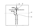
- FIG. 2 is a diagram showing an example of the rotation axis and the inverted axis.
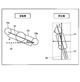
- FIG. 3 is a diagram showing an example of angles on the rotation axis and the inverted axis.
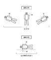
- FIG. 4 is a diagram illustrating an example of a posture of a person that is difficult to express when the rotation axis and the inverted axis are used.
- FIG. 5 is a block diagram illustrating an example of the configuration of the estimation device according to the first embodiment.
- FIG. 6 is a diagram showing an example of a spine vector and a shoulder vector in triaxial polar coordinates.
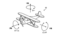
- FIG. 7 is a diagram showing an example of Euler angle expression.
- FIG. 1 is a diagram illustrating an example of the configuration of the estimation system according to the first embodiment.
- FIG. 2 is a diagram showing an example of the rotation axis and the inverted axis.
- FIG. 3 is
- FIG. 8 is a diagram showing an example of comparison between the three-axis polar coordinate expression and the Euler angle expression.
- FIG. 9 is a diagram showing an example of the scoring support screen.
- FIG. 10 is a flowchart illustrating an example of the learning process according to the first embodiment.
- FIG. 11 is a flowchart illustrating an example of the estimation process according to the first embodiment.
- FIG. 12 is a block diagram illustrating an example of the configuration of the estimation device according to the second embodiment.
- FIG. 13 is a diagram illustrating an example of the analysis result storage unit.
- FIG. 14 is a diagram showing another example of the scoring support screen.
- FIG. 15 is a flowchart illustrating an example of the estimation process according to the second embodiment.
- FIG. 16 is a flowchart showing an example of the number of times of somersault.
- FIG. 17 is a flowchart showing an example of the twist number determination process.
- FIG. 18 is a diagram illustrating an example of a computer that executes the
- FIG. 1 is a diagram illustrating an example of the configuration of the estimation system according to the first embodiment.
- the estimation system 1 illustrated in FIG. 1 includes a distance sensor 10 and an estimation device 100. It should be noted that the estimation system 1 is not limited to the number of the distance sensors 10 and may have any number of the distance sensors 10.
- the distance sensor 10 and the estimation device 100 are connected by wire or wirelessly so that they can communicate with each other.
- the estimation system 1 is an example of a system in which the person 5 as a subject is measured by the distance sensor 10 and the estimation device 100 estimates the posture and the like of the person 5 based on the measurement result.
- the distance sensor 10 measures (sensing) the distance of an object for each pixel using an infrared laser or the like, and outputs a distance image.
- the distance image includes the distance to each pixel. That is, the distance image is a depth image representing the depth of the subject viewed from the distance sensor (depth sensor) 10.
- the distance sensor 10 measures, for example, the distance of an object (subject) within a distance of up to about 15 m. In this embodiment, the object is the person 5.
- FIG. 2 is a diagram showing an example of the rotation axis and the inverted axis.
- the posture of the person can be represented by using a vector 21 corresponding to the rotation axis 20 and a vector 23 corresponding to the inverted axis 22.
- the rotation axis 20 represents the direction in the rotation direction of the line connecting the right shoulder and the left shoulder of the person.
- the inverted shaft 22 represents the direction of the spine in the forward rotation direction.
- FIG. 3 is a diagram showing an example of angles on the rotation axis and the inverted axis.
- a line segment 25 connecting the right shoulder 24a and the left shoulder 24b of the person 24 is projected on a horizontal plane (cross section) in the camera coordinate system.
- the angle ⁇ formed by the reference line 26 and the projected line segment 25 on the projected horizontal plane is obtained.
- a spine line 27 obtained by extending a line segment connecting two points on the spine is projected on a plane perpendicular to the line segment 25 and a plane including a vertical straight line in the camera coordinate system.
- the angle ⁇ formed by the reference line 28 and the projected spine line 27 on the projected plane is obtained.
- posture recognition is performed using angles ⁇ and ⁇ .
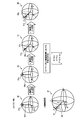
- FIG. 4 is a diagram showing an example of the posture of a person who is difficult to express when the rotation axis and the inverted axis are used.
- the estimation device using the two axes when the left and right shoulders are projected onto the horizontal plane in the posture 32, they are overlapped as shown by the shadow 33, the vector component disappears, and the angle ⁇ in the rotation direction cannot be obtained.
- the posture close to the posture 32 the vector component becomes small, so that the angle ⁇ is likely to be blurred. That is, when the two axes of the rotation axis and the inverted axis are used, it is difficult to represent a posture in which the posture 29 to the posture 32 exist, which reflects somersault or twist.
- the estimation device 100 recognizes the posture and the like of the person 5 based on the distance image input from the distance sensor 10.
- the estimation device 100 acquires a first distance image including information on the distance from the distance sensor 10 to the person 5 who is the first subject.
- the estimation apparatus 100 acquires the first distance image acquired by using the posture recognition prediction model that has learned the triaxial polar coordinate data of the second subject, which is a person when learning the posture recognition prediction model, and the second distance image. From this, the 3-axis polar coordinate data of the first subject is estimated.
- the triaxial polar coordinate data of the second subject connects the spine vector corresponding to the spine of the second subject and the shoulders of the second subject, which are generated based on the coordinate data representing the position of the second subject.
- the estimation device 100 estimates the posture of the person 5 based on the triaxial polar coordinate data of the person 5. Thus, the estimation device 100 can estimate the posture that reflects somersaults and twists.
- FIG. 5 is a block diagram illustrating an example of the configuration of the estimation device according to the first embodiment.
- the estimation device 100 includes a communication unit 110, a display unit 111, an operation unit 112, a storage unit 120, and a control unit 130.
- the estimating apparatus 100 may have various functional units of a known computer other than the functional units shown in FIG. 5, for example, functional units such as various input devices and audio output devices.
- a portable personal computer or the like can be adopted.
- the estimation apparatus 100 may be a stationary personal computer as well as the portable personal computer described above.
- the communication unit 110 is realized by, for example, a NIC (Network Interface Card) or the like.
- the communication unit 110 is a communication interface that is connected to the distance sensor 10 in a wired or wireless manner and controls information communication with the distance sensor 10.
- the display unit 111 is a display device for displaying various information.
- the display unit 111 is realized by, for example, a liquid crystal display as a display device.
- the display unit 111 displays various screens such as the display screen input from the control unit 130.
- the operation unit 112 is an input device that receives various operations from the user of the estimation apparatus 100.
- the operation unit 112 is realized by, for example, a keyboard, a mouse or the like as an input device.
- the operation unit 112 outputs the operation input by the user to the control unit 130 as operation information.
- the operation unit 112 may be realized as a touch panel or the like as an input device, or the display device of the display unit 111 and the input device of the operation unit 112 may be integrated.
- the storage unit 120 is realized by, for example, a RAM (Random Access Memory), a semiconductor memory element such as a flash memory, or a storage device such as a hard disk or an optical disk.
- the storage unit 120 includes a posture recognition prediction model storage unit 121 and a skeleton recognition prediction model storage unit 122.
- the storage unit 120 stores information used for processing by the control unit 130.
- the posture recognition prediction model storage unit 121 stores prediction model information used when determining the posture of the first distance image of the person 5, which is the first subject.
- the posture recognition prediction model storage unit 121 stores, for example, a posture recognition prediction model which is a learned model machine-learned by associating the distance image of the person who is the second subject with the triaxial polar coordinate data.
- the posture recognition prediction model may be a learned model that is machine-learned by associating a distance image of a person who is the second subject with a posture number in which triaxial polar coordinate data is classified.
- the machine learning algorithm for example, random forest or deep learning can be used.
- the skeleton recognition prediction model storage unit 122 stores prediction model information indicating an assumed joint position (skeleton position) for each recognition result of posture recognition.
- the recognition result of the posture recognition for example, the triaxial polar coordinate data or the posture number obtained by classifying the triaxial polar coordinate data can be used.
- the skeleton recognition prediction model storage unit 122 associates, for example, a posture number, a distance image corresponding to the posture number, and information on a joint position of a person (skeleton recognition prediction model information). Although illustration is omitted, it is assumed that there is skeleton recognition prediction model information corresponding to each posture number.
- the skeleton recognition prediction model storage unit 122 is generated by performing machine learning on the triaxial polar coordinate data, the distance image, and the joint position information. Further, the skeleton recognition prediction model storage unit 122 may be generated by performing machine learning on various range images corresponding to the posture numbers and information on the joint positions of the person. In this case, as the machine learning algorithm, for example, random forest or deep learning can be used.
- control unit 130 for example, a program stored in an internal storage device is executed by using a RAM as a work area by a CPU (Central Processing Unit), a GPU (Graphics Processing Unit), an MPU (Micro Processing Unit), or the like. It is realized by. Further, the control unit 130 may be realized by an integrated circuit such as ASIC (Application Specific Integrated Circuit) or FPGA (Field Programmable Gate Array).
- ASIC Application Specific Integrated Circuit
- FPGA Field Programmable Gate Array
- the control unit 130 includes a learning unit 131, an acquisition unit 132, an estimation unit 133, and a recognition unit 134, and realizes or executes the information processing function or action described below. That is, each processing unit of the control unit 130 executes a learning process and an estimation process.
- the internal configuration of the control unit 130 is not limited to the configuration shown in FIG. 5, and may be any other configuration as long as it is a configuration for performing information processing described later.
- the learning unit 131 learns the triaxial polar coordinate data representing the posture of the second subject, which is a learning target, and the distance image to generate a posture recognition prediction model.
- the learning unit 131 may acquire the coordinate data generated by motion capture for the person of the second subject from an unillustrated information processing device for motion capture.
- the learning unit 131 may acquire the coordinate data of the person of the second subject, which is generated using CG (Computer Graphics), from the information processing device for creating CG data.
- the acquired coordinate data is coordinate data representing the position of the person who is the second subject on the three axes of the x, y, and z axes.
- the learning unit 131 calculates the spine vector from the two joints on the spine of the person who is the second subject based on the acquired coordinate data.
- the learning unit 131 calculates an angle ⁇ formed by the y-axis and the calculated spine vector.
- the learning unit 131 projects the spine vector on the xz plane to calculate the angle ⁇ formed with the z axis.
- the learning unit 131 calculates a shoulder vector from the two joints of the right shoulder and the left shoulder of the person of the second subject based on the acquired coordinate data.
- the learning unit 131 obtains a rotation matrix such that the spine vector overlaps the y axis.
- the learning unit 131 rotates the shoulder vector using the obtained rotation matrix.
- the learning unit 131 projects the rotated shoulder vector on the xz plane to calculate the angle ⁇ formed with the x axis. That is, the learning unit 131 calculates the triaxial polar coordinate data having the angles ⁇ , ⁇ , and ⁇ as components.
- the learning unit 131 calculates the distance of each person of the second subject for each pixel of the distance image when the distance sensor 10 is assumed based on the acquired coordinate data.
- the learning unit 131 generates the second distance image based on the acquired coordinate data and the calculated distance from the distance sensor 10 for each pixel. That is, the second distance image is a distance image on the assumption that the distance sensor 10 measures the person who is the second subject to be learned.
- the learning unit 131 learns the generated second distance image and the calculated three-axis polar coordinate data to generate a posture recognition prediction model.
- the learning unit 131 stores the generated posture recognition prediction model in the posture recognition prediction model storage unit 121.
- the learning unit 131 learns the triaxial polar coordinate data of the second subject, or the posture number obtained by classifying the triaxial polar coordinate data, and the second distance image to generate the posture recognition prediction model.
- the triaxial polar coordinate data of the second subject connects the spine vector corresponding to the spine of the second subject and the shoulders of the second subject, which are generated based on the coordinate data representing the position of the second subject. It is 3-axis polar coordinate data based on a shoulder vector corresponding to a line.
- the second distance image is a distance image based on the coordinate data representing the position of the second subject and the distance from the distance sensor 10.
- FIG. 6 is a diagram showing an example of a spine vector and a shoulder vector in triaxial polar coordinates.
- a line segment connecting the cervical vertebra 36 and the lumbar vertebra 37 of the person 35 is defined as a spine vector 38.
- a line segment connecting the right shoulder 39 and the left shoulder 40 of the person 35 is set as a shoulder vector 41.
- the posture of the person is represented by using three angles of the direction ( ⁇ , ⁇ ) of the spine vector 38 and the rotation ( ⁇ ) of the shoulder vector 41.
- the angles ⁇ , ⁇ , and ⁇ are all 0° (0°).
- the defined regions are 0° ⁇ 360°, 0° ⁇ 180°, and 0° ⁇ 360°, respectively.
- the value of the spine vector 38 is divided into the tilt direction and the tilt amount, so as to correspond to a person's abduction.
- the spine is used as the axis when the orientation of the shoulder vector 41 is calculated, so that the person lies sideways.
- the angle ⁇ indicates the rotational component when performing somersault
- the angle ⁇ indicates the rotational component when performing twisting. That is, the spine vector 38 represents the tilt direction and the tilt amount of the second subject, and the shoulder vector 41 represents the rotation direction of the second subject about the spine vector 38.
- FIG. 7 is a diagram showing an example of Euler angle expression.
- the Euler angle representation 43 shown in FIG. 7 uses an orthogonal coordinate system that is generally adopted in conventional animation software.
- a three-dimensional joint angle is expressed using a pitch that is a rotation angle around the x axis, a yaw that is a rotation angle around the y axis, and a roll that is a rotation angle around the z axis. ..
- FIG. 8 is a diagram showing an example of comparison between three-axis polar coordinate expression and Euler angle expression.
- FIG. 8 shows rotations of the x-axis, the y-axis, and the z-axis when the same posture as the three-axis polar coordinate expression 42 is expressed by the Euler angle expression.
- the Euler angle representation 45 that is the initial value, it is assumed that the spine vector 38a overlaps the y axis and the shoulder vector 41a is parallel to the x axis.
- the Euler angle representation 45 is rotated by ⁇ e around the y axis to form the Euler angle representation 46. That is, in the Euler angle representation 46, the reference of ⁇ e rotates by ⁇ e.
- the x-axis becomes the x'axis and the z-axis becomes the z'axis.
- the Euler angle representation 46 is rotated by ⁇ e around the x′ axis to form the Euler angle representation 47.
- the x′ axis becomes the x′′ axis
- the y axis becomes the y′ axis
- the z′ axis becomes the z′′ axis.
- the Euler angle expression 47 is rotated by ⁇ e around the y′ axis to be the Euler angle expression 48.
- the spine vector 38a and the shoulder vector 41a in the Euler angle expression 48 are equal to the spine vector 38 and the shoulder vector 41 in the triaxial polar coordinate expression 42.
- the acquisition unit 132 receives the distance image from the distance sensor 10 via the communication unit 110 and starts acquisition.
- the acquisition unit 132 outputs the acquired distance image to the estimation unit 133 as the first distance image. That is, the acquisition unit 132 starts acquisition of the first distance image including information on the distance from the distance sensor 10 to the first subject.
- the estimation unit 133 When the first distance image is input from the acquisition unit 132, the estimation unit 133 refers to the posture recognition prediction model storage unit 121, and uses the posture recognition prediction model to calculate the triaxial polar coordinates of the person 5 who is the first subject. Estimate the data. That is, the estimation unit 133 recognizes the posture of the person 5. The estimation unit 133 outputs the first distance image and the estimated triaxial polar coordinate data to the recognition unit 134.
- the estimation unit 133 estimates the triaxial polar coordinate data of the first subject from the acquired first distance image using the posture recognition prediction model. Further, the estimation unit 133 estimates the posture of the first subject based on the triaxial polar coordinate data of the first subject. In addition, the estimation unit 133 outputs data regarding the estimated posture in the skeleton recognition processing for recognizing the skeleton of the first subject using the skeleton recognition prediction model selected based on the estimated posture.
- the recognition unit 134 refers to the skeleton recognition prediction model storage unit 122, and based on the estimated triaxial polar coordinate data, the skeleton. Select a predictive model for recognition.
- the recognition unit 134 uses the skeleton recognition prediction model selected by the skeleton recognition prediction model storage unit 122 to determine the three-dimensional position of the skeleton of the person 5, which is the first subject, based on the first distance image, Skeleton information indicating the posture of the person 5 is generated. That is, the recognition unit 134 recognizes the skeleton of the person 5, which is the first subject.
- the recognition unit 134 outputs the recognized skeleton information to the display unit 111 and displays it, for example.
- the recognition unit 134 outputs, for example, the angles of the joints to the display unit 111 based on the recognized skeletal information and causes the display unit 111 to display the angles.
- the recognition unit 134 may also transmit the image of the recognized skeletal information and the angle of each joint to the terminal for the examiner, and cause the terminal to display the scoring support screen.
- FIG. 9 is a diagram showing an example of the scoring support screen.
- the distance sensor 10 measures the person 5
- the estimation device 100 receives the skeleton information, and the scoring support screen 51 is displayed.
- the scoring support screen 51 may display the angle of each joint based on the skeleton information.
- the recognition unit 134 may output the generated skeleton information to, for example, a distance image or a captured image captured by a camera and a processing unit or a processing device that performs skeleton correction processing. That is, the recognition unit 134 can output the generated skeleton information as a skeleton model so that it can be used for CG animation. Furthermore, the recognition unit 134 may process the generated skeleton information into, for example, a specific format and output the skeleton information to an external storage device (not shown) or the like. The recognition unit 134 may generate a three-dimensional model based on the generated skeleton information and output the three-dimensional model to the display unit 111 for display.
- FIG. 10 is a flowchart illustrating an example of the learning process according to the first embodiment.
- the learning unit 131 acquires coordinate data generated by motion capture or CG processing for the person of the second subject from an information processing device for motion capture or CG processing (not shown).
- the learning unit 131 calculates the spine vector from the two joints on the spine of the person who is the second subject based on the acquired coordinate data (step S1).
- the learning unit 131 calculates an angle ⁇ formed by the y-axis and the calculated spine vector (step S2).
- the learning unit 131 projects the spine vector on the xz plane to calculate the angle ⁇ formed with the z axis (step S3).
- the learning unit 131 calculates a shoulder vector from the two joints of the right shoulder and the left shoulder of the person of the second subject based on the acquired coordinate data (step S4).
- the learning unit 131 obtains a rotation matrix such that the spine vector overlaps the y-axis, and rotates the shoulder vector by the obtained rotation matrix (step S5).
- the learning unit 131 projects the rotated shoulder vector on the xz plane to calculate the angle ⁇ formed with the x axis (step S6).
- the learning unit 131 calculates the distance of each person of the second subject for each pixel of the distance image when the distance sensor 10 is assumed based on the acquired coordinate data.
- the learning unit 131 generates the second distance image based on the acquired coordinate data and the calculated distance from the distance sensor 10 for each pixel (step S7).
- the learning unit 131 learns the generated second distance image and the calculated triaxial polar coordinate data ( ⁇ , ⁇ , ⁇ ) to generate a posture recognition prediction model (step S8).
- the learning unit 131 stores the generated posture recognition prediction model in the posture recognition prediction model storage unit 121.
- the estimation apparatus 100 can generate a posture recognition prediction model in which the triaxial polar coordinate data of the second subject and the second distance image are learned.
- FIG. 11 is a flowchart illustrating an example of the estimation process according to the first embodiment.
- the acquisition unit 132 receives the first distance image from the distance sensor 10 and starts acquisition (step S11).
- the acquisition unit 132 outputs the acquired first distance image to the estimation unit 133.
- the estimation unit 133 When the first distance image is input from the acquisition unit 132, the estimation unit 133 refers to the posture recognition prediction model storage unit 121, and uses the posture recognition prediction model to calculate the triaxial polar coordinates of the person 5 who is the first subject. Data is estimated (step S12). The estimation unit 133 outputs the first distance image and the estimated triaxial polar coordinate data to the recognition unit 134. That is, the estimation unit 133 is an example of the output control unit.
- the recognition unit 134 refers to the skeleton recognition prediction model storage unit 122, and based on the estimated triaxial polar coordinate data, the skeleton.
- a prediction model for recognition is selected (step S13).
- the recognition unit 134 uses the skeleton recognition prediction model selected by the skeleton recognition prediction model storage unit 122 to generate skeleton information indicating the posture of the person 5, which is the first subject, based on the first distance image (Ste S14).
- the recognition unit 134 outputs, for example, the recognized skeletal information and the angle of each joint based on the skeletal information to the display unit 111 for display (step S15).
- the estimation device 100 can output the estimation result of the skeleton of the first subject and the angles of the joints. That is, the estimation device 100 provides a method of evaluating the angles of the skeleton and each joint.
- the estimation device 100 acquires the first distance image including the information on the distance from the distance sensor 10 to the person 5 who is the first subject.
- the estimation device 100 uses the posture recognition prediction model acquired by learning the three-axis polar coordinate data of the second subject, which is a person at the time of learning the posture recognition prediction model, and the second distance image to obtain the first
- the 3-axis polar coordinate data of the first subject is estimated from the range image.
- the triaxial polar coordinate data of the second subject connects the spine vector corresponding to the spine of the second subject and the shoulders of the second subject, which are generated based on the coordinate data representing the position of the second subject. It is 3-axis polar coordinate data based on a shoulder vector corresponding to a line.
- the second distance image is a distance image based on the coordinate data representing the position of the second subject and the distance from the distance sensor 10. Further, the estimation device 100 estimates the posture of the person 5 based on the triaxial polar coordinate data of the person 5. As a result, the estimation apparatus 100 can output a more accurate skeleton estimation result by using the skeleton recognition prediction model created for each posture.
- the estimation device 100 outputs data regarding the estimated posture to the skeleton recognition processing for recognizing the skeleton of the first subject using the skeleton recognition prediction model selected based on the estimated posture. As a result, the estimation device 100 can perform skeleton recognition using the data regarding the posture.
- the spine vector represents the inclination direction and the inclination amount of the second subject
- the shoulder vector represents the rotation direction of the second subject with the spine vector as the axis.
- the skeleton was recognized using the estimated three-axis polar coordinate data, but the technique may be determined by directly obtaining the number of somersaults and the number of twists from the three-axis polar coordinate data.
- the embodiment will be described as Example 2.
- the same components as those of the estimation apparatus 100 according to the first embodiment are designated by the same reference numerals, and the description of the overlapping components and operations will be omitted.
- FIG. 12 is a block diagram illustrating an example of the configuration of the estimation device according to the second embodiment.
- the estimation device 200 illustrated in FIG. 12 includes a storage unit 220 and a control unit 230 instead of the storage unit 120 and the control unit 130, as compared with the estimation device 100 of the first embodiment.
- the storage unit 220 includes a technique storage unit 223 and an analysis result storage unit 224, as compared with the storage unit 120.
- the control unit 230 includes a determination unit 236 instead of the recognition unit 134, as compared with the control unit 130.
- the technique storage unit 223 stores the number of somersaults and the number of twists, and the technique of the gymnastics in association with each other. Further, the technique storage unit 223 may store the number of somersaults and the number of twists, the technique (exercise) of gymnastics, and the score in association with each other.
- the analysis result storage unit 224 stores the angles ⁇ and ⁇ for each frame of the first distance image from the start to the end of the technique, and the motion analysis result of the person 5 who is the first subject.
- FIG. 13 is a diagram illustrating an example of the analysis result storage unit. As shown in FIG. 13, the analysis result storage unit 224 has items such as “frame number”, “ ⁇ ”, and “ ⁇ ”.
- “Frame number” is information indicating the frame number of the first distance image from the start to the end of the technique. That is, the first distance image is a moving image corresponding to the time from the start to the end of the technique.
- “ ⁇ ” is information indicating the value of the angle ⁇ for each frame.
- “ ⁇ ” is information indicating the value of the angle ⁇ for each frame.
- the line next to the frame number “final” is set as “motion analysis result”, and the analysis results of the angle ⁇ and the analysis result of the angle ⁇ are stored in the items “ ⁇ ” and “ ⁇ ” of the line, respectively. It In the example of FIG. 13, the analysis result of “one time somersault” based on the angle ⁇ and the analysis result of “twice twist” based on the angle ⁇ are stored.
- the determining unit 236 performs the looping frequency determination process and the twist frequency determination process in parallel according to the first distance image input from the estimation unit 133 and the estimated triaxial polar coordinate data. To execute.
- the estimation unit 133 outputs the first distance image and the estimated triaxial polar coordinate data to the determination unit 236 for each frame of the first distance image.
- the determination unit 236 sets the angle ⁇ to the corresponding frame number ⁇ of the analysis result storage unit 224.
- the initial value of ⁇ pre is 0. That is, the determination unit 236 integrates the increment of the angle ⁇ for each frame into ⁇ diff.
- the determination unit 236 When it is determined that the technique has not ended, the determination unit 236 similarly integrates the increment of the angle ⁇ into ⁇ diff for the next frame of the first distance image to determine whether ⁇ diff exceeds 180. Increase the number of somersaults according to the judgment result. When it is determined that the technique has ended, the determination unit 236 determines the number of somersaults at that time as the number of somersaults of the technique (purpose), and stores it in the ⁇ column corresponding to the operation analysis result of the analysis result storage unit 224. To do.
- the determination unit 236 sets the angle ⁇ to the corresponding frame number ⁇ of the analysis result storage unit 224.
- the initial value of ⁇ pre is 0. That is, the determination unit 236 integrates the increment of the angle ⁇ for each frame into ⁇ diff.
- the determination unit 236 When it is determined that the technique has not ended, the determination unit 236 similarly integrates the increment of the angle ⁇ into ⁇ diff for the next frame of the first distance image to determine whether ⁇ diff exceeds 180. The number of twists is increased according to the determination result.
- the determination unit 236 determines the number of twists at that time as the number of twists of the technique (work), and stores it in the ⁇ column corresponding to the motion analysis result of the analysis result storage unit 224. To do. That is, the determination unit 236 determines at least one of the number of somersaults and the number of twists of the first subject based on the estimated time-series change of the triaxial polar coordinate data.
- the determination unit 236 refers to the technique storage unit 223 and determines the technique based on the determined number of somersaults and twists. Further, the determining unit 236 may acquire the score of the determined technique (purpose). The determination unit 236 outputs the determined technique (purpose), the number of somersaults, and the number of twists to the display unit 111 for display, for example. Further, the determination unit 236 may output and display the determined technique (purpose), the number of somersaults, the number of twists, and the score on the display unit 111.
- the determination unit 236 transmits the determined technique (purpose), the number of somersaults, the number of twists, and the score, and the image of the first subject captured by a camera (not shown) to the terminal for the examiner, and the terminal is sent to the terminal. You may make it display a scoring support screen.
- FIG. 14 is a diagram showing another example of the scoring support screen.
- the terminal 52 for the judge is, for example, a technique (purpose) determined by the estimation device 200 by the distance sensor 10 measuring the person 5, the number of somersaults and the number of twists, and the first subject.
- the image of the person 5 is received and the scoring support screen 53 is displayed.
- the terminal 52 may display the skill score on the scoring support screen 53.
- FIG. 15 is a flowchart illustrating an example of the estimation process according to the second embodiment.
- the process of step S11 of the estimation process is the same as that in the first embodiment, and thus the description thereof is omitted.
- the determination unit 236 of the estimation device 200 executes the following process following the process of step S11.
- the determination unit 236 performs the number of somersaults (step S21) and the number of twists determination process (step S22) in parallel according to the first distance image input from the estimation unit 133 and the estimated triaxial polar coordinate data. Then run.
- FIG. 16 is a flowchart showing an example of the number of times of somersault.
- the determination unit 236 sets the initial value 0 to ⁇ diff (step S211).
- the estimation unit 133 refers to the posture recognition prediction model storage unit 121, and estimates the triaxial polar coordinate data of the person 5 who is the first subject using the posture recognition prediction model (step S212).
- the estimation unit 133 outputs the first distance image and the estimated triaxial polar coordinate data to the determination unit 236.
- the determining unit 236 determines whether or not ⁇ diff exceeds 180 (step S214). When the determination unit 236 determines that ⁇ diff exceeds 180 (step S214: Yes), the determination unit 236 increases the number of somersaults by 0.5. Further, the determination unit 236 subtracts 180 from ⁇ diff (step S215), and proceeds to step S216. When determining unit 236 determines that ⁇ diff does not exceed 180 (step S214: No), the determination unit 236 proceeds to step S216 without increasing the number of somersaults.
- the determination unit 236 determines whether or not the technique has ended (step S216). When the determining unit 236 determines that the technique has not ended (step S216: negative), the determining unit 236 returns to step S212 and performs the same processing for the next frame of the first distance image. When determining that the technique has ended (step S216: Yes), the determining unit 236 determines the number of somersaults at that time as the number of somersaults of the technique (purpose) (step S217), and returns to the original process. Thereby, the determination unit 236 can determine the number of somersaults.
- FIG. 17 is a flowchart showing an example of the twist number determination process.
- the determination unit 236 sets the initial value 0 to ⁇ diff (step S221).
- the estimation unit 133 refers to the posture recognition prediction model storage unit 121, and estimates the triaxial polar coordinate data of the person 5, which is the first subject, using the posture recognition prediction model (step S222).
- the estimation unit 133 outputs the first distance image and the estimated triaxial polar coordinate data to the determination unit 236.
- the determination unit 236 determines whether or not ⁇ diff exceeds 180 (step S224). When the determination unit 236 determines that ⁇ diff exceeds 180 (step S224: Yes), the number of twists is increased by 0.5. Further, the determination unit 236 subtracts 180 from ⁇ diff (step S225), and proceeds to step S226. When the determination unit 236 determines that ⁇ diff does not exceed 180 (step S224: negative), the determination unit 236 proceeds to step S226 without increasing the number of twists.
- the determination unit 236 determines whether or not the technique is completed (step S226). When the determining unit 236 determines that the technique has not ended (step S226: negative), the determining unit 236 returns to step S222 and performs the same process for the next frame of the first distance image. When determining that the technique has ended (step S226: Yes), the determining unit 236 determines the number of twists at that time as the number of twists of the technique (work) (step S227), and returns to the original process. Thereby, the determination unit 236 can determine the number of twists.
- the determination unit 236 refers to the technique storage unit 223 and determines the technique based on the determined number of somersaults and twists (step S23). Further, the determination unit 236 acquires the score of the determined technique (purpose). The determination unit 236 outputs, for example, the determined technique (purpose), the number of somersaults, the number of twists, and the score to the display unit 111 for display (step S24). Thereby, the estimation device 200 can recognize the technique based on the number of times of somersaults and twists.
- the estimation device 200 determines at least one of the number of somersaults and the number of twists of the first subject based on the estimated time-series change of the three-axis polar coordinate data. As a result, the estimation device 200 can recognize the technique based on the number of times of somersaults and twists.
- the person 5, who performs the gymnastics competition was measured to recognize the posture, skeleton, and movement, but the present invention is not limited to this.
- it can also be applied to other scoring competitions such as figure skating, verification of movements in rehabilitation, analysis of forms such as free throws of baseball, golf, and basketball, guidance support for newcomers in factory line work, etc. Good.
- the present invention is not limited to this.
- a plurality of people such as a basketball player and a women's rhythmic gymnastics group, it is sufficient to set an angle of view in which all of them are included and perform distance imaging.
- each component of each part illustrated does not necessarily have to be physically configured as illustrated. That is, the specific form of distribution/integration of each part is not limited to the one shown in the figure, and all or part of the part may be functionally or physically distributed/integrated in arbitrary units according to various loads and usage conditions. Can be configured.
- the recognition unit 134 and the determination unit 135 may be integrated.
- the illustrated processes are not limited to the above order, and may be executed simultaneously or in a different order as long as the contents of the processes are not inconsistent.
- processing functions performed in each device may be executed in whole or in part on the CPU (or arithmetic device such as GPU, MPU, MCU (Micro Controller Unit)).
- various processing functions are executed in whole or in part on a program that is analyzed and executed by a CPU (or an arithmetic unit such as a GPU, MPU, or MCU) or on hardware by a wired logic. It goes without saying that it is good.
- FIG. 18 is a diagram illustrating an example of a computer that executes the estimation program.
- the computer 300 has a CPU 301 that executes various arithmetic processes, an input device 302 that receives data input, and a monitor 303. Further, the computer 300 is for reading a program or the like from a storage medium, a medium reading device 304, an interface device 305 for connecting to various devices, and a wired or wireless connection to the distance sensor 10 or another information processing device. And a communication device 306. Further, the computer 300 has a RAM 307 for temporarily storing various information and a hard disk device 308. Further, each of the devices 301 to 308 is connected to the bus 309.
- the hard disk device 308 stores an estimation program having the same functions as the processing units of the learning unit 131, the acquisition unit 132, the estimation unit 133, and the recognition unit 134 illustrated in FIG.
- the hard disk device 308 also stores a posture recognition prediction model storage unit 121, a skeleton recognition prediction model storage unit 122, and various data for implementing the estimation program.
- the hard disk device 308 may store an estimation program having the same functions as the processing units of the learning unit 131, the acquisition unit 132, the estimation unit 133, and the determination unit 236 illustrated in FIG. 12.
- the hard disk device 308 stores the posture recognition prediction model storage unit 121, the skeleton recognition prediction model storage unit 122, the technique storage unit 223, the analysis result storage unit 224, and various data for implementing the estimation program. It may be done.
- the input device 302 receives input of various information such as operation information from the user of the computer 300, for example.
- the monitor 303 displays various screens such as a display screen for the user of the computer 300, for example.
- a printing device or the like is connected to the interface device 305.
- the communication device 306 has, for example, the same function as the communication unit 110 illustrated in FIGS. 5 and 12 and is connected to the distance sensor 10 and other information processing devices. Exchange.
- the CPU 201 performs various processes by reading each program stored in the hard disk device 308, expanding the program in the RAM 307, and executing the program. Further, these programs can cause the computer 300 to function as the learning unit 131, the acquisition unit 132, the estimation unit 133, and the recognition unit 134 illustrated in FIG. Further, these programs can cause the computer 300 to function as the learning unit 131, the acquisition unit 132, the estimation unit 133, and the determination unit 236 illustrated in FIG. 12.
- the computer 300 may read and execute a program stored in a storage medium readable by the computer 300.
- the storage medium readable by the computer 300 is, for example, a portable recording medium such as a CD-ROM, a DVD (Digital Versatile Disc), a USB (Universal Serial Bus) memory, a semiconductor memory such as a flash memory, a hard disk drive, or the like. ..
- the estimation program may be stored in a device connected to a public line, the Internet, a LAN or the like, and the computer 300 may read the estimation program from these and execute the estimation program.
Landscapes
- Engineering & Computer Science (AREA)
- Theoretical Computer Science (AREA)
- General Physics & Mathematics (AREA)
- Physics & Mathematics (AREA)
- Computer Vision & Pattern Recognition (AREA)
- Multimedia (AREA)
- Software Systems (AREA)
- Human Computer Interaction (AREA)
- General Health & Medical Sciences (AREA)
- Health & Medical Sciences (AREA)
- Medical Informatics (AREA)
- Mathematical Physics (AREA)
- General Engineering & Computer Science (AREA)
- Computing Systems (AREA)
- Evolutionary Computation (AREA)
- Data Mining & Analysis (AREA)
- Artificial Intelligence (AREA)
- Psychiatry (AREA)
- Social Psychology (AREA)
- Physical Education & Sports Medicine (AREA)
- Image Analysis (AREA)
- Measurement Of The Respiration, Hearing Ability, Form, And Blood Characteristics Of Living Organisms (AREA)
Abstract
宙返りやひねりを反映した姿勢を推定できる推定方法等を提供する。推定方法は、センサから第1被写体までの距離の情報を含む第1距離画像を取得する処理をコンピュータが実行する。推定方法は、第2被写体の3軸極座標データと、第2距離画像とを学習した姿勢認識用予測モデルを用いて、第1距離画像から第1被写体の3軸極座標データを推定する処理をコンピュータが実行する。ここで、第2被写体の3軸極座標データは、第2被写体の位置を表す座標データに基づいて生成された、第2被写体の背骨に対応する背骨ベクトル、および、第2被写体の両肩を結ぶ線に対応する肩ベクトルに基づく3軸極座標データである。また、第2距離画像は、第2被写体の位置を表す座標データおよびセンサからの距離に基づく距離画像である。推定方法は、第1被写体の3軸極座標データに基づき、第1被写体の姿勢を推定する処理をコンピュータが実行する。
Description
本発明は、推定方法、推定プログラムおよび推定装置に関する。
従来、人物までの距離を測定する距離センサ(以下、深度センサともいう。)が出力する距離画像(以下、深度画像ともいう。)に基づいて、人物の姿勢や動きを認識する装置がある。当該装置は、例えば、1台の距離センサから出力される距離画像に基づいて、3次元の骨格位置を持つ骨格モデルを抽出する。その後、当該装置は、抽出した骨格モデルに基づいて、人物の動作を特定する。
M. Kitagawa and B. Windser、"MoCap for Artists"、Elsevier/Focal Press、2008、pp.188-193
大島雄治、外1名、「水平面における下胴の動きに着目した疾走動作の三次元動力学」、体育学研究、一般社団法人日本体育学会、2016年6月、第61巻、第1号、p.115-131
長谷川秀太、外2名、「姿勢を考慮したハンドジェスチャーを利用する機器操作の提案・評価」、研究報告、一般社団法人情報処理学会、2012年3月、第2012-HCI-147巻、第24号、p.1-6
体操などの採点支援競技において審判支援や選手強化を行うため、アスリートの骨格の3次元の複雑な動きを認識する技術の確立が要求されている。距離画像から人物の姿勢を検出し、人物の姿勢に応じた骨格認識用予測モデルと距離画像とを用いて骨格認識を行う。従来までの人物の姿勢の検出では、両肩を結ぶ線の自転方向における向きを表す自転軸と、背骨の前転方向における向きを表す倒立軸との2軸を用いて人物の姿勢を検出してきた。しかしながら、この2軸を用いる場合、人物の側転方向の区別がつかない。また、人物が横倒しになると、左右の肩を水平面に射影すると重なるため、ベクトルの成分がなくなり、自転方向の角度も求められない。従って、これらの姿勢が存在する宙返りやひねりを反映した姿勢を推定することが困難である。
一つの側面では、宙返りやひねりを反映した姿勢を推定する推定方法、推定プログラムおよび推定装置を提供することにある。
一つの態様では、推定方法は、センサから第1被写体までの距離の情報を含む第1距離画像を取得する処理をコンピュータが実行する。推定方法は、第2被写体の3軸極座標データと、第2距離画像とを学習した姿勢認識用の予測モデルを用いて、取得した前記第1距離画像から前記第1被写体の3軸極座標データを推定する処理をコンピュータが実行する。ここで、第2被写体の3軸極座標データは、第2被写体の位置を表す座標データに基づいて生成された、第2被写体の背骨に対応する背骨ベクトル、および、第2被写体の両肩を結ぶ線に対応する肩ベクトルに基づく3軸極座標データである。また、第2距離画像は、第2被写体の位置を表す座標データおよびセンサからの距離に基づく距離画像である。推定方法は、前記第1被写体の前記3軸極座標データに基づき、前記第1被写体の姿勢を推定する処理をコンピュータが実行する。
宙返りやひねりを反映した姿勢を推定できる。
以下、図面に基づいて、本願の開示する推定方法、推定プログラムおよび推定装置の実施例を詳細に説明する。なお、本実施例により、開示技術が限定されるものではない。また、以下の実施例は、矛盾しない範囲で適宜組みあわせてもよい。
図1は、実施例1の推定システムの構成の一例を示す図である。図1に示す推定システム1は、距離センサ10と、推定装置100とを有する。なお、推定システム1では、距離センサ10の数は限定されず、任意の数の距離センサ10を有するようにしてもよい。距離センサ10と推定装置100との間は、有線または無線にて、相互に通信可能に接続される。
推定システム1は、被写体である人物5を距離センサ10で測定し、測定結果に基づいて、推定装置100が人物5の姿勢等を推定するシステムの一例である。
距離センサ10は、例えば、赤外線レーザ等を用いて対象物の距離を画素ごとに測定(センシング)し、距離画像を出力する。距離画像には、各画素までの距離が含まれる。つまり、距離画像は、距離センサ(深度センサ)10から見た被写体の深度を表す深度画像である。距離センサ10は、例えば、概ね15mまでの距離にある対象物(被写体)の距離を測定する。本実施例では、対象物は人物5となる。
ここで、図2から図4を用いて、自転軸および倒立軸の2軸を用いる場合における人物の姿勢の検出について説明する。なお、以下の説明では、人物の姿勢の検出を姿勢認識ともいう。図2は、自転軸および倒立軸の一例を示す図である。図2に示すように、人物の姿勢は、自転軸20に対応するベクトル21と、倒立軸22に対応するベクトル23とを用いて表すことができる。このとき、自転軸20は、人物の右肩および左肩を結ぶ線の自転方向における向きを表す。また、倒立軸22は、背骨の前転方向における向きを表す。このように2軸を用いる場合、2関節を結ぶ直線(ベクトル21,23)を基準とする平面に射影し、当該平面内の基準とする直線とのなす角の大きさで姿勢を分類する。
図3は、自転軸および倒立軸における角度の一例を示す図である。図3に示すように、自転軸における角φを求めるには、人物24の右肩24aと左肩24bとを結ぶ線分25を、カメラ座標系における水平面(横断面)に射影する。次に、射影した水平面上において、基準線26と射影した線分25とのなす角φを求める。また、倒立軸における角θを求めるには、線分25とカメラ座標系における鉛直方向の直線を含む平面に垂直な平面に、背骨上の2点を結ぶ線分を延長した背骨ライン27を射影する。次に、射影した平面上において、基準線28と射影した背骨ライン27とのなす角θを求める。2軸を用いる推定装置の場合、角φ,θを用いて姿勢認識を行う。
図4は、自転軸および倒立軸を用いた場合における表現が難しい人物の姿勢の一例を示す図である。図4に示すように、2軸を用いる推定装置の場合、人物の側転方向の姿勢29,30,31は、角φ,θが全て同じ値(=0)となるため、区別がつかない。また、2軸を用いる推定装置の場合、姿勢32において、左右の肩を水平面に射影すると、影33に示すように重なってしまうのでベクトルの成分がなくなり、自転方向の角φが求められない。なお、姿勢32に近い姿勢の場合では、ベクトル成分が小さくなるため、角φがブレやすくなる。すなわち、自転軸および倒立軸の2軸を用いる場合では、姿勢29~姿勢32が存在する宙返りやひねりを反映した姿勢を表現することが難しい。
図1の説明に戻って、推定装置100は、距離センサ10から入力される距離画像に基づいて、人物5の姿勢等を認識する。推定装置100は、距離センサ10から第1被写体である人物5までの距離の情報を含む第1距離画像を取得する。推定装置100は、姿勢認識用予測モデルの学習時の人物である第2被写体の3軸極座標データと、第2距離画像とを学習した姿勢認識用予測モデルを用いて、取得した第1距離画像から第1被写体の3軸極座標データを推定する。ここで、第2被写体の3軸極座標データは、第2被写体の位置を表す座標データに基づいて生成された、第2被写体の背骨に対応する背骨ベクトル、および、第2被写体の両肩を結ぶ線に対応する肩ベクトルに基づく3軸極座標データである。また、第2距離画像は、第2被写体の位置を表す座標データおよび距離センサ10からの距離に基づく距離画像である。推定装置100は、人物5の3軸極座標データに基づき、人物5の姿勢を推定する。これにより、推定装置100は、宙返りやひねりを反映した姿勢を推定できる。
次に、図5を用いて推定装置100の機能構成について説明する。図5は、実施例1の推定装置の構成の一例を示すブロック図である。図5に示すように、推定装置100は、通信部110と、表示部111と、操作部112と、記憶部120と、制御部130とを有する。なお、推定装置100は、図5に示す機能部以外にも既知のコンピュータが有する各種の機能部、例えば各種の入力デバイスや音声出力デバイス等の機能部を有することとしてもかまわない。推定装置100の一例としては、可搬型のパーソナルコンピュータ等を採用できる。なお、推定装置100には、上記の可搬型のパーソナルコンピュータのみならず、据置型のパーソナルコンピュータを採用することもできる。
通信部110は、例えば、NIC(Network Interface Card)等によって実現される。通信部110は、距離センサ10と有線または無線で接続され、距離センサ10との間で情報の通信を司る通信インタフェースである。
表示部111は、各種情報を表示するための表示デバイスである。表示部111は、例えば、表示デバイスとして液晶ディスプレイ等によって実現される。表示部111は、制御部130から入力された表示画面等の各種画面を表示する。
操作部112は、推定装置100のユーザから各種操作を受け付ける入力デバイスである。操作部112は、例えば、入力デバイスとして、キーボードやマウス等によって実現される。操作部112は、ユーザによって入力された操作を操作情報として制御部130に出力する。なお、操作部112は、入力デバイスとして、タッチパネル等によって実現されるようにしてもよく、表示部111の表示デバイスと、操作部112の入力デバイスとは、一体化されるようにしてもよい。
記憶部120は、例えば、RAM(Random Access Memory)、フラッシュメモリ等の半導体メモリ素子、ハードディスクや光ディスク等の記憶装置によって実現される。記憶部120は、姿勢認識用予測モデル記憶部121と、骨格認識用予測モデル記憶部122とを有する。また、記憶部120は、制御部130での処理に用いる情報を記憶する。
姿勢認識用予測モデル記憶部121は、第1被写体である人物5の第1距離画像が、どのような姿勢であるかを判定する際に用いられる予測モデル情報を記憶する。姿勢認識用予測モデル記憶部121は、例えば、第2被写体である人物の距離画像と、3軸極座標データとを対応付けて機械学習した学習済モデルである姿勢認識用予測モデルを記憶する。なお、姿勢認識用予測モデルは、第2被写体である人物の距離画像と、3軸極座標データを分類した姿勢番号とを対応付けて機械学習した学習済モデルであってもよい。機械学習のアルゴリズムとしては、例えば、ランダムフォレストやディープラーニングを用いることができる。
骨格認識用予測モデル記憶部122は、姿勢認識の認識結果ごとの仮定の関節位置(骨格位置)を示す予測モデル情報を記憶する。姿勢認識の認識結果は、例えば、3軸極座標データ、または、3軸極座標データを分類した姿勢番号を用いることができる。骨格認識用予測モデル記憶部122は、例えば、姿勢番号と、係る姿勢番号に対応する距離画像と、人物の関節位置の情報(骨格認識用予測モデル情報)とを対応づける。図示を省略するが、各姿勢番号に対応する骨格認識用予測モデル情報がそれぞれ存在するものとする。なお、骨格認識用予測モデル記憶部122は、3軸極座標データと、距離画像と、関節位置の情報とについて機械学習を行うことで生成される。また、骨格認識用予測モデル記憶部122は、姿勢番号に対応する種々の距離画像と、人物の関節位置の情報とについて機械学習を行うことで生成されるようにしてもよい。この場合、機械学習のアルゴリズムとしては、例えば、ランダムフォレストやディープラーニングを用いることができる。
制御部130は、例えば、CPU(Central Processing Unit)やGPU(Graphics Processing Unit)、MPU(Micro Processing Unit)等によって、内部の記憶装置に記憶されているプログラムがRAMを作業領域として実行されることにより実現される。また、制御部130は、例えば、ASIC(Application Specific Integrated Circuit)やFPGA(Field Programmable Gate Array)等の集積回路により実現されるようにしてもよい。
制御部130は、学習部131と、取得部132と、推定部133と、認識部134とを有し、以下に説明する情報処理の機能や作用を実現または実行する。すなわち、制御部130の各処理部は、学習処理および推定処理を実行する。なお、制御部130の内部構成は、図5に示した構成に限られず、後述する情報処理を行う構成であれば他の構成であってもよい。
学習部131は、学習対象である第2被写体の人物について、当該人物の姿勢を表す3軸極座標データと、距離画像とを学習して姿勢認識用予測モデルを生成する。例えば、学習部131は、第2被写体の人物についてモーションキャプチャによって生成された座標データを、図示しないモーションキャプチャ用の情報処理装置から取得してもよい。例えば、学習部131は、CG(Computer Graphics)を使って生成した第2被写体の人物の座標データをCGデータ作成用の情報処理装置から取得してもよい。取得した座標データは、第2被写体の人物のx,y,z軸の3軸における位置を表す座標データである。
学習部131は、取得した座標データに基づいて、第2被写体の人物の背骨上の2関節から背骨ベクトルを算出する。学習部131は、y軸と、算出した背骨ベクトルのなす角θを算出する。学習部131は、背骨ベクトルをxz平面に射影し、z軸とのなす角φを算出する。
学習部131は、取得した座標データに基づいて、第2被写体の人物の右肩および左肩の2関節から肩ベクトルを算出する。学習部131は、背骨ベクトルがy軸に重なるような回転行列を求める。学習部131は、求めた回転行列を用いて肩ベクトルを回転する。学習部131は、回転後の肩ベクトルをxz平面に射影し、x軸とのなす角ξを算出する。すなわち、学習部131は、角θ,φ,ξを成分とする3軸極座標データを算出する。
学習部131は、取得した座標データに基づいて、第2被写体の人物について、距離センサ10を仮定した場合における距離画像の画素ごとに距離を算出する。学習部131は、取得した座標データ、および、算出した画素ごとの距離センサ10からの距離に基づいて、第2距離画像を生成する。つまり、第2距離画像は、学習対象の第2被写体の人物を距離センサ10で測定したと仮定した場合の距離画像である。
学習部131は、生成した第2距離画像と、算出した3軸極座標データとを学習して姿勢認識用予測モデルを生成する。学習部131は、生成した姿勢認識用予測モデルを姿勢認識用予測モデル記憶部121に記憶する。
言い換えると、学習部131は、第2被写体の3軸極座標データ、または、3軸極座標データを分類した姿勢番号と、第2距離画像とを学習して姿勢認識用予測モデルを生成する。ここで、第2被写体の3軸極座標データは、第2被写体の位置を表す座標データに基づいて生成された、第2被写体の背骨に対応する背骨ベクトル、および、第2被写体の両肩を結ぶ線に対応する肩ベクトルに基づく3軸極座標データである。また、第2距離画像は、第2被写体の位置を表す座標データおよび距離センサ10からの距離に基づく距離画像である。
ここで、図6から図8を用いて、3軸極座標データの3軸極座標表現について説明する。図6は、3軸極座標における背骨ベクトルおよび肩ベクトルの一例を示す図である。図6に示すように、人物35の頚椎36と腰椎37とを結ぶ線分を背骨ベクトル38とする。また、人物35の右肩39と左肩40とを結ぶ線分を肩ベクトル41とする。本実施例の3軸極座標表現42では、背骨ベクトル38の向き(θ,φ)と、肩ベクトル41の回転(ξ)との3つの角度を用いて人物の姿勢を表す。なお、距離センサ10に対して正面正立の場合に角θ,φ,ξは、ともに0°(0度)とする。また、定義域はそれぞれ、0°≦θ<360°、0°≦φ<180°、0°≦ξ<360°とする。
つまり、3軸極座標表現42では、背骨ベクトル38の値を傾く方向と傾いた量とに分けたことで人物の側転に対応する。また、3軸極座標表現42では、肩ベクトル41の向きの算出時の軸を背骨としたことで人物の横倒し姿勢に対応する。これを体操競技に適用すると、角θが宙返り実施時の回転成分を示し、角ξがひねり実施時の回転成分を示すことになる。すなわち、背骨ベクトル38は、第2被写体の傾く方向と、傾いた量とを表し、肩ベクトル41は、背骨ベクトル38を軸とした第2被写体の回転方向を表す。
図7は、オイラー角表現の一例を示す図である。図7に示すオイラー角表現43は、従来のアニメーションソフトで一般的に採用されている直交座標系を利用したものである。オイラー角表現43では、x軸周りの回転角度であるピッチと、y軸周りの回転角度であるヨーと、z軸周りの回転角度であるロールとを用いて、三次元の関節角度を表現する。
図8は、3軸極座標表現とオイラー角表現との比較の一例を示す図である。図8では、3軸極座標表現42と同じ姿勢をオイラー角表現で表す場合におけるx軸、y軸、z軸の回転を表す。まず、初期値であるオイラー角表現45では、背骨ベクトル38aがy軸と重なり、肩ベクトル41aがx軸と平行であるとする。次に、オイラー角表現45を、y軸周りにφe回転してオイラー角表現46とする。つまり、オイラー角表現46では、ξeの基準がφe回転する。このとき、x軸はx’軸となり、z軸はz’軸となる。さらに、オイラー角表現46を、x’軸周りにθe回転してオイラー角表現47とする。このとき、x’軸はx’’軸となり、y軸はy’軸となり、z’軸はz’’軸となる。さらに、オイラー角表現47を、y’軸周りにξe回転してオイラー角表現48とする。
オイラー角表現48の背骨ベクトル38aおよび肩ベクトル41aは、3軸極座標表現42の背骨ベクトル38および肩ベクトル41と等しくなる。3軸極座標表現42とオイラー角表現48とにおける、それぞれの角度の対応は、φ=φe、θ=θe、ξ=ξe-φeとなる。体操競技では、φeは人物の移動とともに時々刻々と変化するため、ξeだけではひねり回転量を推定できない。また、ξ=ξeとならないのは、3軸極座標表現42では距離センサ10の方向をξ=0°と定義しており、オイラー角表現48とは0°の基準が異なるためである。従って、体操競技における宙返りおよびひねり運動を認識する場合には、オイラー角表現48よりも3軸極座標表現42の方が優れていると言える。
図5の説明に戻って、取得部132は、通信部110を介して、距離センサ10から距離画像を受信して取得を開始する。取得部132は、取得した距離画像を第1距離画像として推定部133に出力する。すなわち、取得部132は、距離センサ10から第1被写体までの距離の情報を含む第1距離画像の取得を開始する。
推定部133は、取得部132から第1距離画像が入力されると、姿勢認識用予測モデル記憶部121を参照し、姿勢認識用予測モデルを用いて第1被写体である人物5の3軸極座標データを推定する。つまり、推定部133は、人物5の姿勢を認識する。推定部133は、第1距離画像と、推定した3軸極座標データとを認識部134に出力する。
言い換えると、推定部133は、姿勢認識用予測モデルを用いて、取得した第1距離画像から第1被写体の3軸極座標データを推定する。また、推定部133は、第1被写体の3軸極座標データに基づき、第1被写体の姿勢を推定する。また、推定部133は、推定した姿勢に基づいて選択された骨格認識用予測モデルを用いて第1被写体の骨格を認識する骨格認識処理に、推定した姿勢に関するデータを出力する。
認識部134は、推定部133から第1距離画像と、推定した3軸極座標データが入力されると、骨格認識用予測モデル記憶部122を参照し、推定した3軸極座標データに基づいて、骨格認識用予測モデルを選択する。認識部134は、骨格認識用予測モデル記憶部122の選択した骨格認識用予測モデルを用いて、第1距離画像に基づいて、第1被写体である人物5の骨格の3次元位置を決定し、人物5の姿勢を示す骨格情報を生成する。つまり、認識部134は、第1被写体である人物5の骨格認識を行う。認識部134は、認識した骨格情報を、例えば、表示部111に出力して表示させる。認識部134は、例えば、認識した骨格情報に基づいて各関節の角度を表示部111に出力して表示させる。また、認識部134は、認識した骨格情報の画像と各関節の角度とを審査員用の端末に送信して、当該端末に採点支援画面を表示させるようにしてもよい。
図9は、採点支援画面の一例を示す図である。図9に示すように、審査員用の端末50は、例えば、人物5を距離センサ10が計測して推定装置100が骨格情報を受信し、採点支援画面51を表示する。なお、採点支援画面51には、骨格情報に基づいて各関節の角度を表示するようにしてもよい。
なお、認識部134は、生成した骨格情報を、例えば、距離画像やカメラで撮像された撮像画像と骨格補正処理を行う処理部や処理装置に出力するようにしてもよい。つまり、認識部134は、生成した骨格情報を、例えば骨格モデルとして、CGアニメーションに利用可能に出力したりすることができる。さらに、認識部134は、生成した骨格情報を、例えば、特定のフォーマットに加工して、図示しない外部記憶装置等に出力するようにしてもよい。なお、認識部134は、生成した骨格情報に基づいて、3次元モデルを生成して表示部111に出力して表示するようにしてもよい。
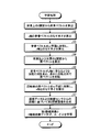
次に、実施例1の推定装置100の動作について説明する。まず、図10を用いて学習処理について説明する。図10は、実施例1の学習処理の一例を示すフローチャートである。
学習部131は、第2被写体の人物についてモーションキャプチャまたはCG処理によって生成された座標データを、図示しないモーションキャプチャ用またはCG処理用の情報処理装置から取得する。学習部131は、取得した座標データに基づいて、第2被写体の人物の背骨上の2関節から背骨ベクトルを算出する(ステップS1)。学習部131は、y軸と、算出した背骨ベクトルのなす角θを算出する(ステップS2)。学習部131は、背骨ベクトルをxz平面に射影し、z軸とのなす角φを算出する(ステップS3)。
学習部131は、取得した座標データに基づいて、第2被写体の人物の右肩および左肩の2関節から肩ベクトルを算出する(ステップS4)。学習部131は、背骨ベクトルがy軸に重なるような回転行列を求め、求めた回転行列で肩ベクトルを回転する(ステップS5)。学習部131は、回転後の肩ベクトルをxz平面に射影し、x軸とのなす角ξを算出する(ステップS6)。
学習部131は、取得した座標データに基づいて、第2被写体の人物について、距離センサ10を仮定した場合における距離画像の画素ごとに距離を算出する。学習部131は、取得した座標データ、および、算出した画素ごとの距離センサ10からの距離に基づいて、第2距離画像を生成する(ステップS7)。
学習部131は、生成した第2距離画像と、算出した3軸極座標データ(θ,φ,ξ)とを学習して姿勢認識用予測モデルを生成する(ステップS8)。学習部131は、生成した姿勢認識用予測モデルを姿勢認識用予測モデル記憶部121に記憶する。これにより、推定装置100は、第2被写体の3軸極座標データと第2距離画像とを学習した姿勢認識用予測モデルを生成できる。
続いて、距離センサ10から取得する第1距離画像について姿勢認識を行う推定処理について説明する。図11は、実施例1の推定処理の一例を示すフローチャートである。
取得部132は、距離センサ10から第1距離画像を受信して取得を開始する(ステップS11)。取得部132は、取得した第1距離画像を推定部133に出力する。
推定部133は、取得部132から第1距離画像が入力されると、姿勢認識用予測モデル記憶部121を参照し、姿勢認識用予測モデルを用いて第1被写体である人物5の3軸極座標データを推定する(ステップS12)。推定部133は、第1距離画像と、推定した3軸極座標データとを認識部134に出力する。すなわち、推定部133は、出力制御部の一例である。
認識部134は、推定部133から第1距離画像と、推定した3軸極座標データが入力されると、骨格認識用予測モデル記憶部122を参照し、推定した3軸極座標データに基づいて、骨格認識用予測モデルを選択する(ステップS13)。
認識部134は、骨格認識用予測モデル記憶部122の選択した骨格認識用予測モデルを用いて、第1距離画像に基づいて、第1被写体である人物5の姿勢を示す骨格情報を生成する(ステップS14)。認識部134は、認識した骨格情報および骨格情報に基づく各関節の角度を、例えば、表示部111に出力して表示させる(ステップS15)。これにより、推定装置100は、第1被写体の骨格および各関節の角度の推定結果を出力できる。すなわち、推定装置100は、骨格および各関節の角度の評価手法を提供する。
このように、推定装置100は、距離センサ10から第1被写体である人物5までの距離の情報を含む第1距離画像を取得する。また、推定装置100は、姿勢認識用予測モデルの学習時の人物である第2被写体の3軸極座標データと、第2距離画像とを学習した姿勢認識用予測モデルを用いて、取得した第1距離画像から第1被写体の3軸極座標データを推定する。ここで、第2被写体の3軸極座標データは、第2被写体の位置を表す座標データに基づいて生成された、第2被写体の背骨に対応する背骨ベクトル、および、第2被写体の両肩を結ぶ線に対応する肩ベクトルに基づく3軸極座標データである。また、第2距離画像は、第2被写体の位置を表す座標データおよび距離センサ10からの距離に基づく距離画像である。また、推定装置100は、人物5の3軸極座標データに基づき、人物5の姿勢を推定する。その結果、推定装置100は、姿勢ごとに作成した骨格認識用予測モデルを使うことで、より精度の高い骨格の推定結果を出力できる。
また、推定装置100は、推定した姿勢に基づいて選択された骨格認識用予測モデルを用いて第1被写体の骨格を認識する骨格認識処理に、推定した姿勢に関するデータを出力する。その結果、推定装置100は、姿勢に関するデータを用いて骨格認識を行うことができる。
また、推定装置100では、背骨ベクトルは、第2被写体の傾く方向と、傾いた量とを表し、肩ベクトルは、背骨ベクトルを軸とした第2被写体の回転方向を表す。その結果、推定装置100は、3軸極座標表現のデータを学習した姿勢認識用予測モデルを生成および利用することができる。
上記実施例1では、推定した3軸極座標データを用いて骨格認識を行ったが、3軸極座標データから宙返り回数およびひねり回数を直接求めて技(わざ)を判定してもよく、この場合の実施の形態につき、実施例2として説明する。なお、実施例1の推定装置100と同一の構成には同一符号を付すことで、その重複する構成および動作の説明については省略する。
図12は、実施例2の推定装置の構成の一例を示すブロック図である。図12に示す推定装置200は、実施例1の推定装置100と比較して、記憶部120および制御部130に代えて記憶部220および制御部230を有する。また、記憶部220は、記憶部120と比較して、技記憶部223および解析結果記憶部224を有する。また、制御部230は、制御部130と比較して、認識部134に代えて決定部236を有する。
技記憶部223は、宙返り回数およびひねり回数と、体操の技(わざ)とを対応付けて記憶する。また、技記憶部223は、宙返り回数およびひねり回数と、体操の技(わざ)と、得点とを対応付けて記憶してもよい。
解析結果記憶部224は、技の開始から終了までの第1距離画像のフレームごとの角θ,ξと、第1被写体である人物5の動作解析結果とを記憶する。図13は、解析結果記憶部の一例を示す図である。図13に示すように、解析結果記憶部224は、「フレーム番号」、「θ」、「ξ」といった項目を有する。
「フレーム番号」は、技の開始から終了までの第1距離画像のフレーム番号を示す情報である。つまり、第1距離画像は、技の開始から終了までの時間に対応する動画像である。「θ」は、フレームごとの角θの値を示す情報である。「ξ」は、フレームごとの角ξの値を示す情報である。また、フレーム番号「最終」の次の行は「動作解析結果」とし、当該行の項目「θ」、「ξ」には、それぞれ角θの解析結果と、角ξの解析結果とが格納される。図13の例では、角θに基づく「1回宙返り」との解析結果と、角ξに基づく「2回ひねり」との解析結果が格納される。
図12の説明に戻って、決定部236は、推定部133から入力される第1距離画像と、推定した3軸極座標データとに応じて、宙返り回数決定処理とひねり回数決定処理とを並行して実行する。なお、実施例2では、推定部133は、第1距離画像のフレームごとに、第1距離画像と、推定した3軸極座標データとを決定部236に出力する。
決定部236は、宙返り回数決定処理として、まず、回数算出用の変数θdiffに初期値を設定する(θdiff=0)。決定部236は、推定部133から第1距離画像と、推定した3軸極座標データ(θ,φ,ξ)とが入力されると、角θを解析結果記憶部224の対応するフレーム番号のθ欄に記憶し、θdiff=θdiff+(θ-θpre)を演算する。なお、当該演算は、θdiff+=θ-θpreとも表す。また、θpreにθを代入する(θpre=θ)。なお、θpreの初期値は0である。つまり、決定部236は、1フレームごとの角θの増加分をθdiffに積算する。
決定部236は、θdiffが180を超えたか否かを判定する。つまり、決定部236は、θdiffが180°を超えたか否かを判定する。決定部236は、θdiffが180を超えたと判定した場合には、宙返り回数を0.5回増加させる。また、決定部236は、θdiffから180を減算し(θdiff=θdiff-180)、技が終了したか否かを判定する。なお、当該減算は、θdiff-=180とも表す。決定部236は、θdiffが180を超えないと判定した場合には、宙返り回数を増加させずに、技が終了したか否かを判定する。
決定部236は、技が終了していないと判定した場合には、第1距離画像の次のフレームについて同様に、角θの増加分をθdiffに積算し、θdiffが180を超えたか否かの判定結果に応じて宙返り回数を増加させる。決定部236は、技が終了したと判定した場合には、その時点における宙返り回数を、技(わざ)の宙返り回数として決定し、解析結果記憶部224の動作解析結果に対応するθ欄に記憶する。
決定部236は、ひねり回数決定処理として、まず、回数算出用の変数ξdiffに初期値を設定する(ξdiff=0)。決定部236は、推定部133から第1距離画像と、推定した3軸極座標データ(θ,φ,ξ)とが入力されると、角ξを解析結果記憶部224の対応するフレーム番号のξ欄に記憶し、ξdiff=ξdiff+(ξ-ξpre)を演算する。なお、当該演算は、ξdiff+=ξ-ξpreとも表す。また、ξpreにξを代入する(ξpre=ξ)。なお、ξpreの初期値は0である。つまり、決定部236は、1フレームごとの角ξの増加分をξdiffに積算する。
決定部236は、ξdiffが180を超えたか否かを判定する。つまり、決定部236は、ξdiffが180°を超えたか否かを判定する。決定部236は、ξdiffが180を超えたと判定した場合には、ひねり回数を0.5回増加させる。また、決定部236は、ξdiffから180を減算し(ξdiff=ξdiff-180)、技が終了したか否かを判定する。なお、当該減算は、ξdiff-=180とも表す。決定部236は、ξdiffが180を超えないと判定した場合には、ひねり回数を増加させずに、技が終了したか否かを判定する。
決定部236は、技が終了していないと判定した場合には、第1距離画像の次のフレームについて同様に、角ξの増加分をξdiffに積算し、ξdiffが180を超えたか否かの判定結果に応じてひねり回数を増加させる。決定部236は、技が終了したと判定した場合には、その時点におけるひねり回数を、技(わざ)のひねり回数として決定し、解析結果記憶部224の動作解析結果に対応するξ欄に記憶する。すなわち、決定部236は、推定した3軸極座標データの時系列変化に基づいて、第1被写体の宙返り回数、および、ひねり回数のうち、少なくとも一方の回数を決定する。
決定部236は、技記憶部223を参照し、決定した宙返り回数およびひねり回数に基づいて技を判定する。また、決定部236は、判定した技(わざ)の得点を取得してもよい。決定部236は、判定した技(わざ)、宙返り回数、および、ひねり回数を、例えば、表示部111に出力して表示させる。また、決定部236は、判定した技(わざ)、宙返り回数、ひねり回数および得点を、表示部111に出力して表示させてもよい。また、決定部236は、判定した技(わざ)、宙返り回数、ひねり回数および得点と、図示しないカメラで撮像された第1被写体の画像とを審査員用の端末に送信して、当該端末に採点支援画面を表示させるようにしてもよい。
図14は、採点支援画面の他の一例を示す図である。図14に示すように、審査員用の端末52は、例えば、人物5を距離センサ10が計測して推定装置200が判定した技(わざ)、宙返り回数およびひねり回数と、第1被写体である人物5の画像とを受信し、採点支援画面53を表示する。なお、端末52は、採点支援画面53に技の得点を表示してもよい。
次に、実施例2の推定装置200の動作について説明する。なお、学習処理は、実施例1と同様であるので、その説明を省略する。図15は、実施例2の推定処理の一例を示すフローチャートである。以下の説明では、推定処理のステップS11の処理は、実施例1と同様であるので、その説明を省略する。
推定装置200の決定部236は、ステップS11の処理に続いて以下の処理を実行する。決定部236は、推定部133から入力される第1距離画像と、推定した3軸極座標データとに応じて、宙返り回数決定処理(ステップS21)と、ひねり回数決定処理(ステップS22)とを並行して実行する。
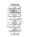
ここで、図16を用いて宙返り回数決定処理について説明する。図16は、宙返り回数決定処理の一例を示すフローチャートである。決定部236は、θdiffに初期値0を設定する(ステップS211)。推定部133は、姿勢認識用予測モデル記憶部121を参照し、姿勢認識用予測モデルを用いて第1被写体である人物5の3軸極座標データを推定する(ステップS212)。推定部133は、第1距離画像と、推定した3軸極座標データとを決定部236に出力する。
決定部236は、推定部133から第1距離画像と、推定した3軸極座標データ(θ,φ,ξ)とが入力されると、角θを解析結果記憶部224の対応するフレーム番号のθ欄に記憶し、θdiff+=θ-θpreを演算する。また、θpreにθを代入する(ステップS213)。
決定部236は、θdiffが180を超えたか否かを判定する(ステップS214)。決定部236は、θdiffが180を超えたと判定した場合には(ステップS214:肯定)、宙返り回数を0.5回増加させる。また、決定部236は、θdiffから180を減算し(ステップS215)、ステップS216に進む。決定部236は、θdiffが180を超えないと判定した場合には(ステップS214:否定)、宙返り回数を増加させずに、ステップS216に進む。
決定部236は、技が終了したか否かを判定する(ステップS216)。決定部236は、技が終了していないと判定した場合には(ステップS216:否定)、ステップS212に戻り、第1距離画像の次のフレームについて同様に処理を行う。決定部236は、技が終了したと判定した場合には(ステップS216:肯定)、その時点における宙返り回数を、技(わざ)の宙返り回数として決定し(ステップS217)、元の処理に戻る。これにより、決定部236は、宙返り回数を決定できる。
次に、図17を用いてひねり回数決定処理について説明する。図17は、ひねり回数決定処理の一例を示すフローチャートである。決定部236は、ξdiffに初期値0を設定する(ステップS221)。推定部133は、姿勢認識用予測モデル記憶部121を参照し、姿勢認識用予測モデルを用いて第1被写体である人物5の3軸極座標データを推定する(ステップS222)。推定部133は、第1距離画像と、推定した3軸極座標データとを決定部236に出力する。
決定部236は、推定部133から第1距離画像と、推定した3軸極座標データ(θ,φ,ξ)とが入力されると、角ξを解析結果記憶部224の対応するフレーム番号のξ欄に記憶し、ξdiff+=ξ-ξpreを演算する。また、ξpreにξを代入する(ステップS223)。
決定部236は、ξdiffが180を超えたか否かを判定する(ステップS224)。決定部236は、ξdiffが180を超えたと判定した場合には(ステップS224:肯定)、ひねり回数を0.5回増加させる。また、決定部236は、ξdiffから180を減算し(ステップS225)、ステップS226に進む。決定部236は、ξdiffが180を超えないと判定した場合には(ステップS224:否定)、ひねり回数を増加させずに、ステップS226に進む。
決定部236は、技が終了したか否かを判定する(ステップS226)。決定部236は、技が終了していないと判定した場合には(ステップS226:否定)、ステップS222に戻り、第1距離画像の次のフレームについて同様に処理を行う。決定部236は、技が終了したと判定した場合には(ステップS226:肯定)、その時点におけるひねり回数を、技(わざ)のひねり回数として決定し(ステップS227)、元の処理に戻る。これにより、決定部236は、ひねり回数を決定できる。
図15の説明に戻って、決定部236は、技記憶部223を参照し、決定した宙返り回数およびひねり回数に基づいて技を判定する(ステップS23)。また、決定部236は、判定した技(わざ)の得点を取得する。決定部236は、判定した技(わざ)、宙返り回数、ひねり回数および得点を、例えば、表示部111に出力して表示させる(ステップS24)。これにより、推定装置200は、宙返りやひねりの回数に基づいて技を認識することができる。
このように、推定装置200は、推定した3軸極座標データの時系列変化に基づいて、第1被写体の宙返り回数、および、ひねり回数のうち、少なくとも一方の回数を決定する。その結果、推定装置200は、宙返りやひねりの回数に基づいて技を認識することができる。
なお、上記各実施例では、体操競技を行う人物5を測定して姿勢、骨格、動作の認識を行ったが、これに限定されない。例えば、フィギュアスケート等の他の採点競技や、リハビリテーションでの動作の検証、野球やゴルフ、バスケットボールのフリースロー等のフォームの分析、工場のライン作業における新人への指導支援等にも適用してもよい。
また、上記各実施例では、第1被写体が一人の場合について説明したが、これに限定されない。例えば、バスケットボールや女子新体操団体等の複数人の場合についても、全員が収まる画角を設定して距離撮像を撮像するようにすればよい。
また、図示した各部の各構成要素は、必ずしも物理的に図示の如く構成されていることを要しない。すなわち、各部の分散・統合の具体的形態は図示のものに限られず、その全部または一部を、各種の負荷や使用状況等に応じて、任意の単位で機能的または物理的に分散・統合して構成することができる。例えば、認識部134と判定部135とを統合してもよい。また、図示した各処理は、上記の順番に限定されるものでなく、処理内容を矛盾させない範囲において、同時に実施してもよく、順序を入れ替えて実施してもよい。
さらに、各装置で行われる各種処理機能は、CPU(またはGPU、MPU、MCU(Micro Controller Unit)等の演算装置)上で、その全部または任意の一部を実行するようにしてもよい。また、各種処理機能は、CPU(またはGPU、MPU、MCU等の演算装置)で解析実行されるプログラム上、またはワイヤードロジックによるハードウェア上で、その全部または任意の一部を実行するようにしてもよいことは言うまでもない。
ところで、上記の各実施例で説明した各種の処理は、予め用意されたプログラムをコンピュータで実行することで実現できる。そこで、以下では、上記の各実施例と同様の機能を有するプログラムを実行するコンピュータの一例を説明する。図18は、推定プログラムを実行するコンピュータの一例を示す図である。
図18に示すように、コンピュータ300は、各種演算処理を実行するCPU301と、データ入力を受け付ける入力装置302と、モニタ303とを有する。また、コンピュータ300は、記憶媒体からプログラム等を読み取る媒体読取装置304と、各種装置と接続するためのインタフェース装置305と、距離センサ10や他の情報処理装置等と有線または無線により接続するための通信装置306とを有する。また、コンピュータ300は、各種情報を一時記憶するRAM307と、ハードディスク装置308とを有する。また、各装置301~308は、バス309に接続される。
ハードディスク装置308には、図5に示した学習部131、取得部132、推定部133および認識部134の各処理部と同様の機能を有する推定プログラムが記憶される。また、ハードディスク装置308には、姿勢認識用予測モデル記憶部121、骨格認識用予測モデル記憶部122、および、推定プログラムを実現するための各種データが記憶される。また、ハードディスク装置308には、図12に示した学習部131、取得部132、推定部133および決定部236の各処理部と同様の機能を有する推定プログラムが記憶されるようにしてもよい。また、ハードディスク装置308には、姿勢認識用予測モデル記憶部121、骨格認識用予測モデル記憶部122、技記憶部223、解析結果記憶部224、および、推定プログラムを実現するための各種データが記憶されるようにしてもよい。
入力装置302は、例えば、コンピュータ300のユーザから操作情報等の各種情報の入力を受け付ける。モニタ303は、例えば、コンピュータ300のユーザに対して表示画面等の各種画面を表示する。インタフェース装置305は、例えば印刷装置等が接続される。通信装置306は、例えば、図5,図12に示した通信部110と同様の機能を有し距離センサ10や他の情報処理装置と接続され、距離センサ10や他の情報処理装置と各種情報をやりとりする。
CPU201は、ハードディスク装置308に記憶された各プログラムを読み出して、RAM307に展開して実行することで、各種の処理を行う。また、これらのプログラムは、コンピュータ300を図5に示した学習部131、取得部132、推定部133および認識部134として機能させることができる。また、これらのプログラムは、コンピュータ300を図12に示した学習部131、取得部132、推定部133および決定部236として機能させることができる。
なお、上記の推定プログラムは、必ずしもハードディスク装置308に記憶されている必要はない。例えば、コンピュータ300が読み取り可能な記憶媒体に記憶されたプログラムを、コンピュータ300が読み出して実行するようにしてもよい。コンピュータ300が読み取り可能な記憶媒体は、例えば、CD-ROMやDVD(Digital Versatile Disc)、USB(Universal Serial Bus)メモリ等の可搬型記録媒体、フラッシュメモリ等の半導体メモリ、ハードディスクドライブ等が対応する。また、公衆回線、インターネット、LAN等に接続された装置にこの推定プログラムを記憶させておき、コンピュータ300がこれらから推定プログラムを読み出して実行するようにしてもよい。
1 推定システム
10 距離センサ
100,200 推定装置
110 通信部
111 表示部
112 操作部
120,220 記憶部
121 姿勢認識用予測モデル記憶部
122 骨格認識用予測モデル記憶部
130,230 制御部
131 学習部
132 取得部
133 推定部
134 認識部
223 技記憶部
224 解析結果記憶部
236 決定部
10 距離センサ
100,200 推定装置
110 通信部
111 表示部
112 操作部
120,220 記憶部
121 姿勢認識用予測モデル記憶部
122 骨格認識用予測モデル記憶部
130,230 制御部
131 学習部
132 取得部
133 推定部
134 認識部
223 技記憶部
224 解析結果記憶部
236 決定部
Claims (15)
- センサから第1被写体までの距離の情報を含む第1距離画像を取得し、
第2被写体の位置を表す座標データに基づいて生成された、前記第2被写体の背骨に対応する背骨ベクトル、および、前記第2被写体の両肩を結ぶ線に対応する肩ベクトルに基づく3軸極座標データと、前記第2被写体の前記座標データおよび前記センサからの距離に基づく第2距離画像とを学習した姿勢認識用予測モデルを用いて、取得した前記第1距離画像から前記第1被写体の3軸極座標データを推定し、
前記第1被写体の前記3軸極座標データに基づき、前記第1被写体の姿勢を推定する、
処理をコンピュータが実行することを特徴とする推定方法。 - さらに、推定した前記姿勢に基づいて選択された骨格認識用予測モデルを用いて前記第1被写体の骨格を認識する骨格認識処理に、推定した前記姿勢に関するデータを出力する、
処理をコンピュータが実行することを特徴とする請求項1に記載の推定方法。 - さらに、推定した前記3軸極座標データの時系列変化に基づいて、前記第1被写体の宙返り回数、および、ひねり回数のうち、少なくとも一方の回数を決定する、
処理をコンピュータが実行することを特徴とする請求項1に記載の推定方法。 - 前記背骨ベクトルは、前記第2被写体の傾く方向と、傾いた量とを表し、前記肩ベクトルは、前記背骨ベクトルを軸とした前記第2被写体の回転方向を表す、
ことを特徴とする請求項1に記載の推定方法。 - センサから第1被写体までの距離の情報を含む第1距離画像を取得し、
第2被写体の位置を表す座標データに基づいて生成された、前記第2被写体の背骨に対応する背骨ベクトル、および、前記第2被写体の両肩を結ぶ線に対応する肩ベクトルに基づく3軸極座標データと、前記第2被写体の前記座標データおよび前記センサからの距離に基づく第2距離画像とを学習した姿勢認識用予測モデルを用いて、取得した前記第1距離画像から前記第1被写体の3軸極座標データを推定し、
推定した前記3軸極座標データの時系列変化に基づいて、前記第1被写体の宙返り回数、および、ひねり回数のうち、少なくとも一方の回数を決定する、
処理をコンピュータが実行することを特徴とする推定方法。 - センサから第1被写体までの距離の情報を含む第1距離画像を取得し、
第2被写体の位置を表す座標データに基づいて生成された、前記第2被写体の背骨に対応する背骨ベクトル、および、前記第2被写体の両肩を結ぶ線に対応する肩ベクトルに基づく3軸極座標データと、前記第2被写体の前記座標データおよび前記センサからの距離に基づく第2距離画像とを学習した姿勢認識用予測モデルを用いて、取得した前記第1距離画像から前記第1被写体の3軸極座標データを推定し、
前記第1被写体の前記3軸極座標データに基づき、前記第1被写体の姿勢を推定する、
処理をコンピュータに実行させることを特徴とする推定プログラム。 - さらに、推定した前記姿勢に基づいて選択された骨格認識用予測モデルを用いて前記第1被写体の骨格を認識する骨格認識処理に、推定した前記姿勢に関するデータを出力する、
処理をコンピュータに実行させることを特徴とする請求項6に記載の推定プログラム。 - さらに、推定した前記3軸極座標データの時系列変化に基づいて、前記第1被写体の宙返り回数、および、ひねり回数のうち、少なくとも一方の回数を決定する、
処理をコンピュータに実行させることを特徴とする請求項6に記載の推定プログラム。 - 前記背骨ベクトルは、前記第2被写体の傾く方向と、傾いた量とを表し、前記肩ベクトルは、前記背骨ベクトルを軸とした前記第2被写体の回転方向を表す、
ことを特徴とする請求項6に記載の推定プログラム。 - センサから第1被写体までの距離の情報を含む第1距離画像を取得し、
第2被写体の位置を表す座標データに基づいて生成された、前記第2被写体の背骨に対応する背骨ベクトル、および、前記第2被写体の両肩を結ぶ線に対応する肩ベクトルに基づく3軸極座標データと、前記第2被写体の前記座標データおよび前記センサからの距離に基づく第2距離画像とを学習した姿勢認識用予測モデルを用いて、取得した前記第1距離画像から前記第1被写体の3軸極座標データを推定し、
推定した前記3軸極座標データの時系列変化に基づいて、前記第1被写体の宙返り回数、および、ひねり回数のうち、少なくとも一方の回数を決定する、
処理をコンピュータに実行させることを特徴とする推定プログラム。 - センサから第1被写体までの距離の情報を含む第1距離画像を取得する取得部と、
第2被写体の位置を表す座標データに基づいて生成された、前記第2被写体の背骨に対応する背骨ベクトル、および、前記第2被写体の両肩を結ぶ線に対応する肩ベクトルに基づく3軸極座標データと、前記第2被写体の前記座標データおよび前記センサからの距離に基づく第2距離画像とを学習した姿勢認識用予測モデルを用いて、取得した前記第1距離画像から前記第1被写体の3軸極座標データを推定する推定部と、
前記第1被写体の前記3軸極座標データに基づき、前記第1被写体の姿勢を推定する姿勢推定部と、
を有することを特徴とする推定装置。 - さらに、推定した前記姿勢に基づいて選択された骨格認識用予測モデルを用いて前記第1被写体の骨格を認識する骨格認識処理に、推定した前記姿勢に関するデータを出力する出力制御部、
を有することを特徴とする請求項11に記載の推定装置。 - さらに、推定した前記3軸極座標データの時系列変化に基づいて、前記第1被写体の宙返り回数、および、ひねり回数のうち、少なくとも一方の回数を決定する決定部、
を有することを特徴とする請求項11に記載の推定装置。 - 前記背骨ベクトルは、前記第2被写体の傾く方向と、傾いた量とを表し、前記肩ベクトルは、前記背骨ベクトルを軸とした前記第2被写体の回転方向を表す、
ことを特徴とする請求項11に記載の推定装置。 - センサから第1被写体までの距離の情報を含む第1距離画像を取得する取得部と、
第2被写体の位置を表す座標データに基づいて生成された、前記第2被写体の背骨に対応する背骨ベクトル、および、前記第2被写体の両肩を結ぶ線に対応する肩ベクトルに基づく3軸極座標データと、前記第2被写体の前記座標データおよび前記センサからの距離に基づく第2距離画像とを学習した姿勢認識用予測モデルを用いて、取得した前記第1距離画像から前記第1被写体の3軸極座標データを推定する推定部と、
推定した前記3軸極座標データの時系列変化に基づいて、前記第1被写体の宙返り回数、および、ひねり回数のうち、少なくとも一方の回数を決定する決定部と、
を有することを特徴とする推定装置。
Priority Applications (3)
| Application Number | Priority Date | Filing Date | Title |
|---|---|---|---|
| JP2020559657A JP7124888B2 (ja) | 2018-12-13 | 2018-12-13 | 推定方法、推定プログラムおよび推定装置 |
| PCT/JP2018/045976 WO2020121500A1 (ja) | 2018-12-13 | 2018-12-13 | 推定方法、推定プログラムおよび推定装置 |
| US17/335,143 US20210286983A1 (en) | 2018-12-13 | 2021-06-01 | Estimation method, and computer-readable recording medium recording estimation program |
Applications Claiming Priority (1)
| Application Number | Priority Date | Filing Date | Title |
|---|---|---|---|
| PCT/JP2018/045976 WO2020121500A1 (ja) | 2018-12-13 | 2018-12-13 | 推定方法、推定プログラムおよび推定装置 |
Related Child Applications (1)
| Application Number | Title | Priority Date | Filing Date |
|---|---|---|---|
| US17/335,143 Continuation US20210286983A1 (en) | 2018-12-13 | 2021-06-01 | Estimation method, and computer-readable recording medium recording estimation program |
Publications (1)
| Publication Number | Publication Date |
|---|---|
| WO2020121500A1 true WO2020121500A1 (ja) | 2020-06-18 |
Family
ID=71075434
Family Applications (1)
| Application Number | Title | Priority Date | Filing Date |
|---|---|---|---|
| PCT/JP2018/045976 Ceased WO2020121500A1 (ja) | 2018-12-13 | 2018-12-13 | 推定方法、推定プログラムおよび推定装置 |
Country Status (3)
| Country | Link |
|---|---|
| US (1) | US20210286983A1 (ja) |
| JP (1) | JP7124888B2 (ja) |
| WO (1) | WO2020121500A1 (ja) |
Cited By (4)
| Publication number | Priority date | Publication date | Assignee | Title |
|---|---|---|---|---|
| US20220138458A1 (en) * | 2020-10-30 | 2022-05-05 | Kabushiki Kaisha Toshiba | Estimation device, estimation system, estimation method and program |
| WO2023037401A1 (ja) * | 2021-09-07 | 2023-03-16 | 富士通株式会社 | 骨格認識方法、骨格認識プログラム、及び体操競技採点支援装置 |
| CN116351037A (zh) * | 2021-12-28 | 2023-06-30 | 株式会社Drax | 人工智能训练指导装置及方法 |
| EP4480927A1 (de) | 2023-06-21 | 2024-12-25 | PBTechnology, s.r.o | Behandlung von flüssigkeiten zur veränderung ihrer eigenschaften |
Families Citing this family (2)
| Publication number | Priority date | Publication date | Assignee | Title |
|---|---|---|---|---|
| CN113673316B (zh) * | 2021-07-09 | 2025-10-03 | 深圳市巨龙科教网络有限公司 | 人体摔倒识别方法、装置、终端及存储介质 |
| KR102672531B1 (ko) * | 2021-11-09 | 2024-06-07 | 주식회사 피앤씨솔루션 | 딥러닝 기반의 포즈 추정을 활용한 의료 영상에서의 척추 위치 자동 추정 방법 및 장치 |
Citations (3)
| Publication number | Priority date | Publication date | Assignee | Title |
|---|---|---|---|---|
| JP2013022705A (ja) * | 2011-07-25 | 2013-02-04 | Sony Corp | ロボット装置及びロボット装置の制御方法、コンピューター・プログラム、並びにロボット・システム |
| JP2018128897A (ja) * | 2017-02-09 | 2018-08-16 | 国立大学法人名古屋大学 | 対象物の姿勢等を検出する検出方法、検出プログラム |
| WO2018189795A1 (ja) * | 2017-04-10 | 2018-10-18 | 富士通株式会社 | 認識装置、認識方法および認識プログラム |
Family Cites Families (6)
| Publication number | Priority date | Publication date | Assignee | Title |
|---|---|---|---|---|
| US20150297949A1 (en) * | 2007-06-12 | 2015-10-22 | Intheplay, Inc. | Automatic sports broadcasting system |
| US8109858B2 (en) * | 2004-07-28 | 2012-02-07 | William G Redmann | Device and method for exercise prescription, detection of successful performance, and provision of reward therefore |
| US8175326B2 (en) * | 2008-02-29 | 2012-05-08 | Fred Siegel | Automated scoring system for athletics |
| US9185361B2 (en) * | 2008-07-29 | 2015-11-10 | Gerald Curry | Camera-based tracking and position determination for sporting events using event information and intelligence data extracted in real-time from position information |
| US8744121B2 (en) * | 2009-05-29 | 2014-06-03 | Microsoft Corporation | Device for identifying and tracking multiple humans over time |
| US9990857B2 (en) * | 2015-07-01 | 2018-06-05 | Grafty, Inc. | Method and system for visual pedometry |
-
2018
- 2018-12-13 JP JP2020559657A patent/JP7124888B2/ja active Active
- 2018-12-13 WO PCT/JP2018/045976 patent/WO2020121500A1/ja not_active Ceased
-
2021
- 2021-06-01 US US17/335,143 patent/US20210286983A1/en not_active Abandoned
Patent Citations (3)
| Publication number | Priority date | Publication date | Assignee | Title |
|---|---|---|---|---|
| JP2013022705A (ja) * | 2011-07-25 | 2013-02-04 | Sony Corp | ロボット装置及びロボット装置の制御方法、コンピューター・プログラム、並びにロボット・システム |
| JP2018128897A (ja) * | 2017-02-09 | 2018-08-16 | 国立大学法人名古屋大学 | 対象物の姿勢等を検出する検出方法、検出プログラム |
| WO2018189795A1 (ja) * | 2017-04-10 | 2018-10-18 | 富士通株式会社 | 認識装置、認識方法および認識プログラム |
Non-Patent Citations (1)
| Title |
|---|
| KUROSE, RYUNOSUKE: "Non-official translation: Action Mapping Analysis of Tennis Video Using Attitude Estimation", ITE TECHNICAL REPORT, vol. 40, no. 28, 24 August 2016 (2016-08-24), pages 77 - 80 * |
Cited By (4)
| Publication number | Priority date | Publication date | Assignee | Title |
|---|---|---|---|---|
| US20220138458A1 (en) * | 2020-10-30 | 2022-05-05 | Kabushiki Kaisha Toshiba | Estimation device, estimation system, estimation method and program |
| WO2023037401A1 (ja) * | 2021-09-07 | 2023-03-16 | 富士通株式会社 | 骨格認識方法、骨格認識プログラム、及び体操競技採点支援装置 |
| CN116351037A (zh) * | 2021-12-28 | 2023-06-30 | 株式会社Drax | 人工智能训练指导装置及方法 |
| EP4480927A1 (de) | 2023-06-21 | 2024-12-25 | PBTechnology, s.r.o | Behandlung von flüssigkeiten zur veränderung ihrer eigenschaften |
Also Published As
| Publication number | Publication date |
|---|---|
| US20210286983A1 (en) | 2021-09-16 |
| JPWO2020121500A1 (ja) | 2021-09-30 |
| JP7124888B2 (ja) | 2022-08-24 |
Similar Documents
| Publication | Publication Date | Title |
|---|---|---|
| JP7124888B2 (ja) | 推定方法、推定プログラムおよび推定装置 | |
| CN101836237B (zh) | 用于选择所呈现图形的观看配置的方法和系统 | |
| JP6143469B2 (ja) | 情報処理装置、情報処理方法及びプログラム | |
| JP7127650B2 (ja) | 認識プログラム、認識方法および認識装置 | |
| JP6369811B2 (ja) | 歩行解析システムおよび歩行解析プログラム | |
| JP7682285B2 (ja) | マーカレス運動解析を改善するための方法 | |
| JP2025024232A (ja) | 運動可視化システムおよび運動可視化方法 | |
| JP6783646B2 (ja) | 選択支援装置、選択支援システムおよび選択支援方法 | |
| Kim et al. | Golf swing analysis system with a dual band and motion analysis algorithm | |
| WO2019116495A1 (ja) | 技認識プログラム、技認識方法および技認識システム | |
| CN116740618A (zh) | 一种运动视频动作评估方法、系统、计算机设备及介质 | |
| US10252136B2 (en) | Swing diagnosis apparatus, swing diagnosis system, swing diagnosis method, and recording medium | |
| KR101795474B1 (ko) | 골프자세 교정방법 및 이를 이용한 골프자세 교정시스템 | |
| CN115205329B (zh) | 运动检测的方法、装置、可穿戴设备及存储介质 | |
| US12496493B2 (en) | Systems and method for segmentation of movement repetitions and extraction of performance metrics | |
| JP7482471B2 (ja) | 学習モデルの生成方法 | |
| CN117352126A (zh) | 肌肉受力可视化方法、装置、计算机设备以及存储介质 | |
| JP7011030B1 (ja) | ゴルフスイング解析システム、ゴルフスイング解析方法及びプログラム | |
| JP7419969B2 (ja) | 生成方法、生成プログラムおよび情報処理装置 | |
| JPWO2022149190A5 (ja) | ||
| TWI822473B (zh) | 提供動作改善資訊的方法、處理控制裝置以及系統 | |
| WO2024105991A1 (en) | Information processing apparatus, information processing method, and program | |
| US20260120315A1 (en) | Approaches to generating semi-synthetic training data for real-time estimation of pose and systems for implementing the same | |
| JP7005737B1 (ja) | ゴルフスイング解析システム、ゴルフスイング解析方法及びプログラム | |
| CN116071829A (zh) | 动作识别方法及装置 |
Legal Events
| Date | Code | Title | Description |
|---|---|---|---|
| 121 | Ep: the epo has been informed by wipo that ep was designated in this application |
Ref document number: 18943203 Country of ref document: EP Kind code of ref document: A1 |
|
| ENP | Entry into the national phase |
Ref document number: 2020559657 Country of ref document: JP Kind code of ref document: A |
|
| NENP | Non-entry into the national phase |
Ref country code: DE |
|
| 122 | Ep: pct application non-entry in european phase |
Ref document number: 18943203 Country of ref document: EP Kind code of ref document: A1 |