WO2020121400A1 - Medical device, applicator, and clip unit - Google Patents
Medical device, applicator, and clip unit Download PDFInfo
- Publication number
- WO2020121400A1 WO2020121400A1 PCT/JP2018/045450 JP2018045450W WO2020121400A1 WO 2020121400 A1 WO2020121400 A1 WO 2020121400A1 JP 2018045450 W JP2018045450 W JP 2018045450W WO 2020121400 A1 WO2020121400 A1 WO 2020121400A1
- Authority
- WO
- WIPO (PCT)
- Prior art keywords
- hook
- base
- deformable portion
- power transmission
- arm
- Prior art date
Links
- 230000005540 biological transmission Effects 0.000 claims abstract description 29
- 238000005452 bending Methods 0.000 claims description 7
- 210000000078 claw Anatomy 0.000 description 25
- 238000003825 pressing Methods 0.000 description 12
- 230000004048 modification Effects 0.000 description 10
- 238000012986 modification Methods 0.000 description 10
- 238000003780 insertion Methods 0.000 description 8
- 230000037431 insertion Effects 0.000 description 8
- 239000000463 material Substances 0.000 description 6
- 238000000034 method Methods 0.000 description 6
- 229910052751 metal Inorganic materials 0.000 description 4
- 239000002184 metal Substances 0.000 description 4
- 230000008569 process Effects 0.000 description 4
- 238000005219 brazing Methods 0.000 description 3
- 229910045601 alloy Inorganic materials 0.000 description 2
- 239000000956 alloy Substances 0.000 description 2
- 230000006835 compression Effects 0.000 description 2
- 238000007906 compression Methods 0.000 description 2
- 239000000470 constituent Substances 0.000 description 2
- 238000010586 diagram Methods 0.000 description 2
- 230000000694 effects Effects 0.000 description 2
- 238000005476 soldering Methods 0.000 description 2
- 238000003466 welding Methods 0.000 description 2
- 229910000684 Cobalt-chrome Inorganic materials 0.000 description 1
- 230000001154 acute effect Effects 0.000 description 1
- 230000008901 benefit Effects 0.000 description 1
- 230000008859 change Effects 0.000 description 1
- 239000010952 cobalt-chrome Substances 0.000 description 1
- 239000012141 concentrate Substances 0.000 description 1
- 230000003111 delayed effect Effects 0.000 description 1
- 238000005304 joining Methods 0.000 description 1
- 229910001000 nickel titanium Inorganic materials 0.000 description 1
- 239000011347 resin Substances 0.000 description 1
- 229920005989 resin Polymers 0.000 description 1
- 239000010935 stainless steel Substances 0.000 description 1
- 229910001220 stainless steel Inorganic materials 0.000 description 1
- 230000009466 transformation Effects 0.000 description 1
Images


Classifications
-
- A—HUMAN NECESSITIES
- A61—MEDICAL OR VETERINARY SCIENCE; HYGIENE
- A61B—DIAGNOSIS; SURGERY; IDENTIFICATION
- A61B17/00—Surgical instruments, devices or methods, e.g. tourniquets
- A61B17/12—Surgical instruments, devices or methods, e.g. tourniquets for ligaturing or otherwise compressing tubular parts of the body, e.g. blood vessels, umbilical cord
- A61B17/128—Surgical instruments, devices or methods, e.g. tourniquets for ligaturing or otherwise compressing tubular parts of the body, e.g. blood vessels, umbilical cord for applying or removing clamps or clips
- A61B17/1285—Surgical instruments, devices or methods, e.g. tourniquets for ligaturing or otherwise compressing tubular parts of the body, e.g. blood vessels, umbilical cord for applying or removing clamps or clips for minimally invasive surgery
-
- A—HUMAN NECESSITIES
- A61—MEDICAL OR VETERINARY SCIENCE; HYGIENE
- A61B—DIAGNOSIS; SURGERY; IDENTIFICATION
- A61B17/00—Surgical instruments, devices or methods, e.g. tourniquets
- A61B17/12—Surgical instruments, devices or methods, e.g. tourniquets for ligaturing or otherwise compressing tubular parts of the body, e.g. blood vessels, umbilical cord
- A61B17/12009—Implements for ligaturing other than by clamps or clips, e.g. using a loop with a slip knot
- A61B17/12013—Implements for ligaturing other than by clamps or clips, e.g. using a loop with a slip knot for use in minimally invasive surgery, e.g. endoscopic surgery
-
- A—HUMAN NECESSITIES
- A61—MEDICAL OR VETERINARY SCIENCE; HYGIENE
- A61B—DIAGNOSIS; SURGERY; IDENTIFICATION
- A61B17/00—Surgical instruments, devices or methods, e.g. tourniquets
- A61B17/12—Surgical instruments, devices or methods, e.g. tourniquets for ligaturing or otherwise compressing tubular parts of the body, e.g. blood vessels, umbilical cord
- A61B17/122—Clamps or clips, e.g. for the umbilical cord
- A61B17/1222—Packages or dispensers therefor
-
- A—HUMAN NECESSITIES
- A61—MEDICAL OR VETERINARY SCIENCE; HYGIENE
- A61B—DIAGNOSIS; SURGERY; IDENTIFICATION
- A61B17/00—Surgical instruments, devices or methods, e.g. tourniquets
- A61B17/12—Surgical instruments, devices or methods, e.g. tourniquets for ligaturing or otherwise compressing tubular parts of the body, e.g. blood vessels, umbilical cord
- A61B17/122—Clamps or clips, e.g. for the umbilical cord
- A61B17/1227—Spring clips
-
- A—HUMAN NECESSITIES
- A61—MEDICAL OR VETERINARY SCIENCE; HYGIENE
- A61B—DIAGNOSIS; SURGERY; IDENTIFICATION
- A61B17/00—Surgical instruments, devices or methods, e.g. tourniquets
- A61B17/32—Surgical cutting instruments
- A61B17/3205—Excision instruments
- A61B17/32056—Surgical snare instruments
Definitions
- the arm portion 20 has a pair of arms, a first arm 21 and a second arm 22.
- the first arm 21 and the second arm 22 have claws 21a and 22a at their tip ends, respectively.
- the base end portion 20a is formed in a U shape.
- the arm portion 20 is made of metal including alloy. Examples of the material of the arm portion 20 include stainless steel, cobalt chrome alloy, nickel titanium alloy and the like.
- the first arm 21 and the second arm 22 are expanded in the initial state shown in FIG. When the first arm 21 and the second arm 22 approach each other from the initial state, the elastic force of the material causes a biasing force to return to the initial state.
- the base 20a and the hook 70 move to the outside of the holding tube 30 through the base end opening 30b, but the engagement state between the base 20a and the hook 70 is preferably maintained.
- the engagement between the base 20a and the hook 70 is released, and the clip unit 10 is separated from the applicator 50.
- the operation of the hook 70 during the lock operation will be described in detail.
- the second deforming portion is centered regardless of the magnitude of the traction force F.
- the plate-like portions 76 and 78 do not rotate. Therefore, if the amount of force required to rotate the claws 75 and 77 about the first deformed portion is larger than the amount of locking force when the arm sandwiches a hard tissue, the plate-shaped portion centered on the second deformed portion. Even if the amount of force required for rotating the arms 76 and 78 is set to be smaller than the amount of lock force when the arm sandwiches a hard tissue, the connection between the hook 70 and the base 20a is not released before locking.
- the second deformable portions 762 and 782 are more easily deformed than the first deformable portions 752 and 772, so that the plate-shaped portions 76 and 78 having the second deformable portion as a center can rotate.
- the force required for movement can be set significantly smaller than the lock force.
- the timing at which the component force F2 is generated is earlier than that in the first embodiment including the hook surface 753, and the connection is released smoothly.
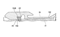
- the hook surface 753B is inclined so as to form an obtuse angle ⁇ 2 on the base end side with respect to the central axis X1 in the initial state.
- the contact portion P2 between the hook surface 753B and the base surface 754 is located closer to the central axis X1 than the contact portion P in the cross section shown in FIG.
- FIGS. 16 to 19 A second embodiment of the present invention will be described with reference to FIGS. 16 to 19.
- the same components as those already described will be designated by the same reference numerals and redundant description will be omitted.
- Claw members 175 and 177 are attached to the rear ends of the first arm 121 and the second arm 122, respectively.
- the claw member 175 has a first deformable portion 1752 and a hook surface 1753.
- the claw member 177 has a first deformable portion 1772 and a hook surface 1773.
- the claw members 175 and 177 can be formed of metal or the like, and may be formed of the same material as the first arm 121 and the second arm 122.
- the claw members 175 and 177 can be fixed to the first arm 121 and the second arm 122 by welding, soldering, bonding, brazing, or the like.
- the operating wire 52 and the clip unit 120 are connected by the claw members 175, 177 sandwiching the base 153.
- the portions of the first arm 121 and the second arm 122 that are behind the joint portion 123 function as the plate-shaped portions 124 and 125, and the plate-shaped portions. Regions near the joint 123 in 124 and 125 function as second deforming portions 124a and 125a, respectively.
- the first deformable portion 1752 and the second deformable portion 1772 are located away from the baseline B3 of the first arm 121 and the baseline B4 of the second arm 122, respectively. That is, in this embodiment, the clip unit has the hook 170 at the rear end of the arm portion 120, and the operation wire has the base.
Abstract
This ligation device comprises: a treatment part; a long, narrow power transmission member for operating the treatment part; and a link that connects the power transmission member and the treatment part in a separable manner. The link has: a hook comprising a first deformation part and a second deformation part that are deformed by the force received from the power transmission member; and base that can engage with the hook. When in a coupled state in which the power transmission member and a clip unit are coupled, the first deformation part is positioned away from a base line. The base line is a line that passes through the second deformation part and a portion where the hook and the base are in contact when in the coupled state.
Description
本発明は、医療機器、より詳しくは、結紮装置、並びにこの結紮装置を構成するアプリケータおよびクリップユニットに関する。
The present invention relates to a medical device, more specifically, a ligation device, and an applicator and a clip unit that constitute the ligation device.
内視鏡を用いて行う処置として、クリップユニットを使った結紮が知られている。クリップユニットは一対のアームを備えている。一対のアームが組織を挟んだ状態で一対のアームを所定量牽引すると、一対のアームが組織を強く締め付けた状態でロックされる。
As a procedure performed using an endoscope, ligation using a clip unit is known. The clip unit includes a pair of arms. When the pair of arms are pulled by a predetermined amount with the pair of arms sandwiching the tissue, the pair of arms are locked while the tissue is tightly clamped.
クリップユニットは、アプリケータに装着された状態で体内に導入される。クリップユニットは組織を結紮した状態で体内に留置されるため、一対のアームがロックされた後にアプリケータから切り離す必要がある。
The clip unit is introduced into the body while it is attached to the applicator. Since the clip unit is placed in the body with the tissue ligated, it is necessary to separate the clip unit from the applicator after the pair of arms are locked.
アプリケータとクリップユニットとの連結を解除する態様がいくつか知られている。例えば、アプリケータとクリップユニットとを連結する部材を破断する態様、部材を破断させずに変形させて連結を解除する態様、部材を回動させて連結を解除する態様(例えば、特許文献1参照。)などである。
変形による連結解除は、小片が生じない点で破断による連結解除に比して優れている。変形による連結解除は、部材と接続された操作伝達部材の牽引操作のみで連結解除できる点で回動による連結解除に比して優れている。 There are some known modes for releasing the connection between the applicator and the clip unit. For example, a mode in which a member that connects the applicator and the clip unit is broken, a mode in which the member is deformed without being broken to release the connection, and a mode in which the member is rotated to release the connection (for example, see Patent Document 1). .) and so on.
Decoupling due to deformation is superior to decoupling due to breakage in that small pieces do not occur. The decoupling due to deformation is superior to the decoupling due to rotation in that the connection can be released only by pulling the operation transmission member connected to the member.
操作者は、一対のアームを閉じさせて対象組織を締め付け、把持位置などを確認しながら結紮が十分であることを確認する。結紮が不十分であると判断した場合には、一対のアームを開かせて対象組織の締め付けを解除し、再度結紮操作を行う。そして、結紮が十分であると判断した場合には、アームをロックする。この時、クリップユニットのアームをロックするために必要な操作力量(ロック力量)が、対象組織を結紮するために必要な力量よりも大幅に大きいことで、操作者は力量のギャップを認識することができ、誤ってアームをロックしてしまうことなく操作を行うことができる。
クリップユニットのアームをロックするために必要な操作力量(ロック力量)の大きさは、アームが挟んだ対象組織から受ける反力により変化する。対象組織が硬いと、ロック力量は大きくなる。
変形による連結解除をクリップユニットに適用する場合、ロックが完了する前に連結が解除されると、組織を結紮できない。したがって、連結解除に必要な操作力量(解除力量)は、通常、ロック力量よりも大きく設定される。また、上述した力量ギャップを確保する観点から、ロック力量が更に大きく設定されることもある。ここで、アームが平均的な硬さの組織を挟んだ場合のロック力量を基準にして解除力量を設定すると、硬い組織を挟んだ場合にロックが完了していないにもかかわらず連結が解除される可能性がある。アームが硬い組織を挟んだ場合のロック力量を基準にして解除力量を設定するとこのような可能性をなくせるが、解除力量が非常に大きくなり、操作しにくくなる可能性がある。 The operator closes the target tissue by closing the pair of arms, and confirms that the ligation is sufficient while confirming the grasping position and the like. When it is determined that the ligation is insufficient, the pair of arms are opened to release the tightening of the target tissue, and the ligation operation is performed again. Then, when it is determined that the ligation is sufficient, the arm is locked. At this time, the operation force required to lock the arm of the clip unit (locking force) is significantly larger than the force required to ligate the target tissue, so that the operator recognizes the force gap. The operation can be performed without accidentally locking the arm.
The amount of operating force (locking force) required to lock the arm of the clip unit changes depending on the reaction force received from the target tissue sandwiched by the arm. If the target tissue is hard, the amount of locking force becomes large.
When applying decoupling to the clip unit, the tissue cannot be ligated if the connection is released before the lock is completed. Therefore, the operation force amount (release force amount) required to release the connection is usually set to be larger than the lock force amount. Further, from the viewpoint of securing the above-mentioned force gap, the lock force amount may be set to be larger. Here, if you set the release force based on the amount of lock force when the arm sandwiches a tissue of average hardness, the connection is released when the hard tissue is sandwiched even though the lock is not completed. There is a possibility. Setting the release force amount based on the lock force amount when the arm sandwiches a hard tissue can eliminate such a possibility, but the release force amount becomes very large, and it may be difficult to operate.
上記事情を踏まえ、本発明は、硬い組織を確実に結紮でき、かつ連結解除の操作が容易な医療機器を提供することを目的とする。
In view of the above circumstances, an object of the present invention is to provide a medical device that can reliably ligate hard tissues and that is easy to disconnect.
本発明の第一の態様は、処置部と、処置部を操作するための細長の動力伝達部材と、動力伝達部材と処置部とを切り離し可能に連結するリンクとを備える医療機器である。
リンクは、動力伝達部材から受ける力で変形する第一変形部および第二変形部を有するフックと、フックと係合可能なベースとを有する。
動力伝達部材と処置部とが連結した連結状態において、第一変形部は、基線から離れた位置にある。基線とは、連結状態におけるフックとベースとの接触部分と第二変形部とを通る線である。 A first aspect of the present invention is a medical device including a treatment section, an elongated power transmission member for operating the treatment section, and a link that detachably connects the power transmission member and the treatment section.
The link has a hook having a first deformable portion and a second deformable portion which are deformed by a force received from the power transmission member, and a base engageable with the hook.
In the connected state in which the power transmission member and the treatment section are connected, the first deformable section is located at a position away from the base line. The base line is a line passing through the contact portion between the hook and the base and the second deformable portion in the connected state.
本発明の第二の態様は、ベースを有する処置部が装着されるアプリケータである。
このアプリケータは、処置部を操作するための細長の動力伝達部材と、動力伝達部材と接続され、ベースと係合可能なフックとを備える。
フックは、動力伝達部材から受ける力で変形する第一変形部および第二変形部を有し、フックとベースとが連結した連結状態において、第一変形部は、基線から離れた位置にある。基線とは、連結状態におけるフックとベースとの接触部分と第二変形部とを通る線である。 A second aspect of the present invention is an applicator to which a treatment section having a base is attached.
The applicator includes an elongated power transmission member for operating the treatment section, and a hook connected to the power transmission member and engageable with the base.
The hook has a first deforming portion and a second deforming portion that are deformed by a force received from the power transmission member, and the first deforming portion is located away from the base line in a connected state in which the hook and the base are connected. The base line is a line passing through the contact portion between the hook and the base and the second deformable portion in the connected state.
本発明の第三の態様は、先端部にベースが設けられた動力伝達部材を備えるアプリケータに装着されるクリップユニットである。
このクリップユニットは、第一アームと、第二アームと、ベースに係合可能なフックとを備える。
フックは、動力伝達部材から伝達される力で変形する第一変形部および第二変形部を有し、フックとベースとが連結した連結状態において、第一変形部は、基線から離れた位置にある。基線とは、連結状態におけるフックとベースとの接触部分と第二変形部とを通る線である。 A third aspect of the present invention is a clip unit that is attached to an applicator that includes a power transmission member having a base provided at its tip.
The clip unit includes a first arm, a second arm, and a hook engageable with the base.
The hook has a first deformable portion and a second deformable portion that are deformed by the force transmitted from the power transmission member, and in the connected state where the hook and the base are coupled, the first deformable portion is located at a position away from the base line. is there. The base line is a line passing through the contact portion between the hook and the base and the second deformable portion in the connected state.
本発明によれば、操作伝達部材の牽引操作のみで処置部を切り離すことができ、かつ切り離すために必要な牽引力量が過大となりにくい。
According to the present invention, the treatment portion can be separated only by the pulling operation of the operation transmitting member, and the amount of pulling force required for disconnecting is unlikely to be excessive.
本発明の第一実施形態について、図1から図15を参照して説明する。
図1は、本実施形態の医療機器である結紮装置1の外観を示す図である。結紮装置1は、体内に留置されるクリップユニット(処置部)10と、クリップユニット10を操作するためのアプリケータ50とを備えている。クリップユニット10は、アプリケータ50の先端(遠位端)に装着される。 A first embodiment of the present invention will be described with reference to FIGS. 1 to 15.
FIG. 1 is a diagram showing an appearance of aligation device 1 which is a medical device of this embodiment. The ligation device 1 includes a clip unit (treatment section) 10 placed inside the body, and an applicator 50 for operating the clip unit 10. The clip unit 10 is attached to the tip (distal end) of the applicator 50.
図1は、本実施形態の医療機器である結紮装置1の外観を示す図である。結紮装置1は、体内に留置されるクリップユニット(処置部)10と、クリップユニット10を操作するためのアプリケータ50とを備えている。クリップユニット10は、アプリケータ50の先端(遠位端)に装着される。 A first embodiment of the present invention will be described with reference to FIGS. 1 to 15.
FIG. 1 is a diagram showing an appearance of a
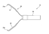
図2は、クリップユニット10の外観を示す図である。図3は、クリップユニット10の断面図である。図2に示すように、クリップユニット10は、アーム部20と、アーム部20の一部が収容された押さえ管(保持部材)30とを備えている。
FIG. 2 is a view showing the outer appearance of the clip unit 10. FIG. 3 is a cross-sectional view of the clip unit 10. As shown in FIG. 2, the clip unit 10 includes an arm portion 20 and a pressing tube (holding member) 30 in which a part of the arm portion 20 is housed.
アーム部20は、第一アーム21および第二アーム22の一対のアームを有する。第一アーム21および第二アーム22は、それぞれ先端部に爪21aおよび22aを有する。図3に示すように、アーム部20の基端部(ベース)20aにおいて、第一アーム部21と第二アーム22とが接続されている。基端部20aは、U字状に形成されている。
アーム部20は、合金を含む金属で形成されている。アーム部20の材質としては、ステンレス鋼、コバルトクロム合金、ニッケルチタン合金などを例示できる。
第一アーム21および第二アーム22は、図2に示す初期状態において拡開している。第一アーム21および第二アーム22は、初期状態から互いに接近すると、材料の弾性力により、初期状態に戻ろうとする付勢力が生じる。 Thearm portion 20 has a pair of arms, a first arm 21 and a second arm 22. The first arm 21 and the second arm 22 have claws 21a and 22a at their tip ends, respectively. As shown in FIG. 3, at the base end portion (base) 20 a of the arm portion 20, the first arm portion 21 and the second arm 22 are connected. The base end portion 20a is formed in a U shape.
Thearm portion 20 is made of metal including alloy. Examples of the material of the arm portion 20 include stainless steel, cobalt chrome alloy, nickel titanium alloy and the like.
Thefirst arm 21 and the second arm 22 are expanded in the initial state shown in FIG. When the first arm 21 and the second arm 22 approach each other from the initial state, the elastic force of the material causes a biasing force to return to the initial state.
アーム部20は、合金を含む金属で形成されている。アーム部20の材質としては、ステンレス鋼、コバルトクロム合金、ニッケルチタン合金などを例示できる。
第一アーム21および第二アーム22は、図2に示す初期状態において拡開している。第一アーム21および第二アーム22は、初期状態から互いに接近すると、材料の弾性力により、初期状態に戻ろうとする付勢力が生じる。 The
The
The
押さえ管30は、金属や樹脂等で形成された筒状の部材である。図3に示すように、アーム部20の基端部20aは、押さえ管30内に収容されている。アーム部20の先端部は、押さえ管の先端開口30aから突出している。押さえ管30の基端開口30bは、先端開口30aよりも小さい。
The pressing tube 30 is a tubular member made of metal, resin, or the like. As shown in FIG. 3, the base end portion 20 a of the arm portion 20 is housed in the pressing tube 30. The tip portion of the arm portion 20 projects from the tip opening 30a of the pressing tube. The base end opening 30b of the pressing tube 30 is smaller than the tip end opening 30a.
図4は、押さえ管30の内部を図3と異なる方向から見た図である。図4に示すように、アーム部20の各アームの中間部には、係止部23が設けられており、係止部23において各アーム21、22の幅方向の寸法が大きくなっている(図4には第一アーム21のみ見えている)。各係止部23は、第一アーム21と第二アーム22とが接近することにより、基端開口30bを通過することができる。基端開口30bを通過後に第一アーム21と第二アーム22とが離間すると、係止部23は、基端開口30bを通過できなくなる。その結果、アーム部20は、一対のアームが閉じた状態でロックされる。
押さえ管30の内部には、コイルバネ31が配置されている。コイルバネ31の前端は、第一アーム21および第二アーム22の後面に接触できる。コイルバネ31の後端は、基端開口30bを有する押さえ管の後端面32と接触できる。
上述したアーム部20および押さえ管30の基本構造は公知であり、例えば、PCT国際公開2014/181676に開示されている。 FIG. 4 is a view of the inside of thepresser tube 30 viewed from a direction different from that in FIG. As shown in FIG. 4, a locking portion 23 is provided at an intermediate portion of each arm of the arm portion 20, and in the locking portion 23, the widthwise dimensions of the arms 21 and 22 are increased ( Only the first arm 21 is visible in FIG. 4). Each locking portion 23 can pass through the base end opening 30b when the first arm 21 and the second arm 22 approach each other. When the first arm 21 and the second arm 22 are separated from each other after passing through the base end opening 30b, the locking portion 23 cannot pass through the base end opening 30b. As a result, the arm portion 20 is locked with the pair of arms closed.
Acoil spring 31 is arranged inside the pressing tube 30. The front end of the coil spring 31 can contact the rear surfaces of the first arm 21 and the second arm 22. The rear end of the coil spring 31 can come into contact with the rear end surface 32 of the pressing tube having the base end opening 30b.
The basic structure of thearm portion 20 and the presser tube 30 described above is known and is disclosed in, for example, PCT International Publication 2014/181676.
押さえ管30の内部には、コイルバネ31が配置されている。コイルバネ31の前端は、第一アーム21および第二アーム22の後面に接触できる。コイルバネ31の後端は、基端開口30bを有する押さえ管の後端面32と接触できる。
上述したアーム部20および押さえ管30の基本構造は公知であり、例えば、PCT国際公開2014/181676に開示されている。 FIG. 4 is a view of the inside of the
A
The basic structure of the
アプリケータ50は、図1に示すように、細長の挿入部51と、挿入部51に通された操作ワイヤ(動力伝達部材)52と、挿入部51に接続された操作部60とを備える。
挿入部51としては、例えばコイルで形成されたシースを使用できる。
操作部60は、挿入部51と接続された本体61と、本体61に対して摺動可能に取り付けられたスライダ62とを有する。
操作ワイヤ52としては、たとえば金属素線からなる撚線ワイヤを使用できる。操作ワイヤ52の基端部は、スライダ62と接続されている。スライダ62を本体61に対して移動させると、挿入部51内で操作ワイヤ52を進退させることができる。 As shown in FIG. 1, theapplicator 50 includes an elongated insertion portion 51, an operation wire (power transmission member) 52 passed through the insertion portion 51, and an operation portion 60 connected to the insertion portion 51.
As theinsertion portion 51, for example, a sheath formed of a coil can be used.
Theoperation unit 60 has a main body 61 connected to the insertion unit 51, and a slider 62 slidably attached to the main body 61.
As theoperation wire 52, for example, a stranded wire made of a metal element wire can be used. The proximal end portion of the operation wire 52 is connected to the slider 62. By moving the slider 62 with respect to the main body 61, the operation wire 52 can be advanced and retracted in the insertion portion 51.
挿入部51としては、例えばコイルで形成されたシースを使用できる。
操作部60は、挿入部51と接続された本体61と、本体61に対して摺動可能に取り付けられたスライダ62とを有する。
操作ワイヤ52としては、たとえば金属素線からなる撚線ワイヤを使用できる。操作ワイヤ52の基端部は、スライダ62と接続されている。スライダ62を本体61に対して移動させると、挿入部51内で操作ワイヤ52を進退させることができる。 As shown in FIG. 1, the
As the
The
As the
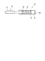
図5は、クリップユニット10が装着されたアプリケータ50先端部の拡大断面図である。
操作ワイヤ52の先端には、クリップユニット10と係合するフック70が固定されている。図5に示すように、操作ワイヤ52の先端部は押さえ管30内に進入し、フック70とアーム部20の基端部20aとが係合している。フック70の外形寸法は、コイルバネ31の内径よりわずかに小さい。
以降の説明において、基端部20aを「ベース20a」と称することがある。フック70とベース20aとは、アプリケータ50とクリップユニット10とを連結するリンク80を構成する。 FIG. 5 is an enlarged cross-sectional view of the tip of theapplicator 50 to which the clip unit 10 is attached.
Ahook 70 that engages with the clip unit 10 is fixed to the tip of the operation wire 52. As shown in FIG. 5, the distal end portion of the operation wire 52 enters the holding tube 30, and the hook 70 and the base end portion 20a of the arm portion 20 are engaged with each other. The outer dimension of the hook 70 is slightly smaller than the inner diameter of the coil spring 31.
In the following description, thebase end portion 20a may be referred to as the "base 20a". The hook 70 and the base 20a form a link 80 that connects the applicator 50 and the clip unit 10.
操作ワイヤ52の先端には、クリップユニット10と係合するフック70が固定されている。図5に示すように、操作ワイヤ52の先端部は押さえ管30内に進入し、フック70とアーム部20の基端部20aとが係合している。フック70の外形寸法は、コイルバネ31の内径よりわずかに小さい。
以降の説明において、基端部20aを「ベース20a」と称することがある。フック70とベース20aとは、アプリケータ50とクリップユニット10とを連結するリンク80を構成する。 FIG. 5 is an enlarged cross-sectional view of the tip of the
A
In the following description, the
図6は、フック70の拡大図である。フック70は、操作ワイヤ52と接続される後部71と、ベース20aと係合する前部72とを有する。
後部71は、前後方向両端に近づくにつれて徐々に縮小する紡錘状に形成され、後端に開口する有底の穴71aを有する。操作ワイヤ52の先端部は、穴71a内に進入している。操作ワイヤ52とフック70とは、例えばロウ付け等により接続されている。本実施形態においてはフック70と操作ワイヤ52とは、同軸の状態を保持して接続されている。 FIG. 6 is an enlarged view of thehook 70. The hook 70 has a rear portion 71 connected to the operation wire 52 and a front portion 72 engaging with the base 20a.
Therear portion 71 is formed in a spindle shape that gradually shrinks toward both ends in the front-rear direction, and has a bottomed hole 71a opening at the rear end. The tip of the operation wire 52 has entered the hole 71a. The operation wire 52 and the hook 70 are connected, for example, by brazing. In the present embodiment, the hook 70 and the operation wire 52 are connected while maintaining a coaxial state.
後部71は、前後方向両端に近づくにつれて徐々に縮小する紡錘状に形成され、後端に開口する有底の穴71aを有する。操作ワイヤ52の先端部は、穴71a内に進入している。操作ワイヤ52とフック70とは、例えばロウ付け等により接続されている。本実施形態においてはフック70と操作ワイヤ52とは、同軸の状態を保持して接続されている。 FIG. 6 is an enlarged view of the
The
前部72は、一対の係合アーム73および74を有する。係合アーム73は、ベース20aと接触する爪部75と、爪部75と後部71とを接続する板状部76とを有する。係合アーム74は、係合アーム73と同様に、爪部77および板状部78を有し、係合アーム73と同一の形状を有する。係合アーム73および74は、フック70の中心軸線X1に対して線対称となる位置に設けられている。
以下、係合アーム73の形状および構造について詳細に説明するが、係合アーム74についても同様である。 Thefront portion 72 has a pair of engagement arms 73 and 74. The engagement arm 73 has a claw portion 75 that contacts the base 20 a and a plate-shaped portion 76 that connects the claw portion 75 and the rear portion 71. Like the engaging arm 73, the engaging arm 74 has a claw portion 77 and a plate-shaped portion 78, and has the same shape as the engaging arm 73. The engagement arms 73 and 74 are provided at positions symmetrical with respect to the central axis X1 of the hook 70.
Hereinafter, the shape and structure of theengagement arm 73 will be described in detail, but the same applies to the engagement arm 74.
以下、係合アーム73の形状および構造について詳細に説明するが、係合アーム74についても同様である。 The
Hereinafter, the shape and structure of the
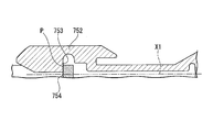
板状部76と爪部75との接続部位より前方における爪部75の内面には、切り欠き751が形成されている。爪部75において、切り欠き751が形成された領域は、構成材料が少ないことにより曲げ剛性が低下しており、第一変形部752として機能する。切り欠き751の三次元形状については、特に制限はない。
第一変形部752よりも前方には、ベース20aの前面(ベース面)754に係止される係止面(フック面)753が形成されている。係止面753は、図6に示す断面において、中心軸線X1と交差する方向に延びている。係止面753よりも前側の部分は、図6に示す断面において、前端に近づくにつれて徐々に縮小するテーパー状に形成されている。 Anotch 751 is formed on the inner surface of the claw portion 75 in front of the connection portion between the plate-shaped portion 76 and the claw portion 75. In the claw portion 75, the region in which the cutout 751 is formed has a reduced bending rigidity due to a small amount of constituent material, and functions as the first deformable portion 752. There is no particular limitation on the three-dimensional shape of the cutout 751.
A locking surface (hook surface) 753 that is locked to the front surface (base surface) 754 of thebase 20a is formed in front of the first deformable portion 752. The locking surface 753 extends in a direction intersecting the central axis X1 in the cross section shown in FIG. A portion on the front side of the locking surface 753 is formed in a taper shape that gradually shrinks toward the front end in the cross section shown in FIG.
第一変形部752よりも前方には、ベース20aの前面(ベース面)754に係止される係止面(フック面)753が形成されている。係止面753は、図6に示す断面において、中心軸線X1と交差する方向に延びている。係止面753よりも前側の部分は、図6に示す断面において、前端に近づくにつれて徐々に縮小するテーパー状に形成されている。 A
A locking surface (hook surface) 753 that is locked to the front surface (base surface) 754 of the
板状部76は、中心軸線X1と平行または略平行に延びている。したがって、本実施形態において、板状部76は、操作ワイヤ52と平行または略平行に延びている。板状部76と後部71との接続部位Tより後方には、切り欠き761が形成されている。板状部76は、前部71や後部72よりも構成材料が少ないことにより変形しやすい。特に、接続部位T付近の板状部76は、フック70とベース20aとの係合部位から最も遠く、かつ厚みの変化が大きいため応力が集中しやすい。その結果、接続部位T付近の板状部76は、第二変形部762として機能する。第二変形部762の曲げ剛性は、第一変形部752の曲げ剛性よりも小さい。
The plate-shaped portion 76 extends parallel or substantially parallel to the central axis X1. Therefore, in the present embodiment, the plate-shaped portion 76 extends parallel or substantially parallel to the operation wire 52. A cutout 761 is formed behind the connection portion T between the plate portion 76 and the rear portion 71. The plate-shaped portion 76 is less likely to be deformed than the front portion 71 and the rear portion 72 because the constituent material is less. In particular, the plate-like portion 76 near the connecting portion T is farthest from the engaging portion between the hook 70 and the base 20a, and has a large change in thickness, so that stress tends to concentrate. As a result, the plate-shaped portion 76 near the connection site T functions as the second deformable portion 762. The bending rigidity of the second deforming portion 762 is smaller than the bending rigidity of the first deforming portion 752.
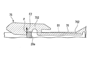
係合アーム73および74は、アーム部20の開閉方向と直交する方向からベース20aを挟み込んでいる。フック70とベース20aとが係合した状態において、フック面753とベース面754とは、第一変形部752よりも前方で接触しているため、第一変形部752は、第二変形部762よりもフック面753に近い。さらに、係合アーム73において、第一変形部752は、フック面753と第二変形部762とを結ぶ線として定義される基線B1から離れた位置にある。本実施形態において、基線B1は中心軸線X1と平行である。
The engagement arms 73 and 74 sandwich the base 20a from a direction orthogonal to the opening/closing direction of the arm section 20. In the state where the hook 70 and the base 20a are engaged with each other, the hook surface 753 and the base surface 754 are in contact with each other in front of the first deformable portion 752. Therefore, the first deformable portion 752 is the second deformable portion 762. Closer to the hook surface 753. Furthermore, in the engagement arm 73, the first deformable portion 752 is located away from the base line B1 defined as a line connecting the hook surface 753 and the second deformable portion 762. In this embodiment, the base line B1 is parallel to the central axis line X1.
係合アーム74は、係合アーム73と同様に、切り欠き771、第一変形部772、フック面773、切り欠き781、および第二変形部782を有する。係合アーム74において、第一変形部772は、フック面773と第二変形部782とを結ぶ線として定義される基線B2から離れた位置にある。本実施形態において、基線B2は中心軸線X1と平行である。
Like the engagement arm 73, the engagement arm 74 has a notch 771, a first deformable portion 772, a hook surface 773, a notch 781, and a second deformable portion 782. In the engaging arm 74, the first deformable portion 772 is located away from the base line B2 defined as a line connecting the hook surface 773 and the second deformable portion 782. In this embodiment, the base line B2 is parallel to the central axis line X1.
図5に示すように、挿入部51の先端には、硬質のガイドパイプ55が取り付けられている。ガイドパイプ55の先端側領域の内径は、押さえ管30の外径よりも大きく、押さえ管30が進入できる。操作ワイヤ52には、ストッパ56が取り付けられている。ストッパ56の形状や寸法は、ガイドパイプ55内に進入できないように設定されているため、ストッパ56がガイドパイプ55の後端と接触すると、操作ワイヤ52はそれ以上前進できない。
As shown in FIG. 5, a hard guide pipe 55 is attached to the tip of the insertion portion 51. The inner diameter of the tip end side region of the guide pipe 55 is larger than the outer diameter of the holding pipe 30, and the holding pipe 30 can enter. A stopper 56 is attached to the operation wire 52. Since the shape and size of the stopper 56 are set so as not to enter the guide pipe 55, when the stopper 56 comes into contact with the rear end of the guide pipe 55, the operation wire 52 cannot advance any further.
上記のように構成された結紮装置1の使用時の動作について説明する。結紮装置1は、内視鏡のチャンネルを経由して体内に導入される。結紮装置1を内視鏡に挿入する際、使用者はスライダ62を所定量後退させて、アーム部20が閉じ、かつロックされていない状態で挿入する。アーム部20が閉じたクリップユニット10および挿入部51の先端部を、アウターシース53内に収容した状態で内視鏡に挿入してもよい。
The operation of the ligation device 1 configured as described above when in use will be described. The ligation device 1 is introduced into the body via the channel of the endoscope. When inserting the ligation device 1 into the endoscope, the user retracts the slider 62 by a predetermined amount to insert the ligature device 1 with the arm portion 20 closed and unlocked. The clip unit 10 with the arm portion 20 closed and the distal end portion of the insertion portion 51 may be inserted into the endoscope while being housed in the outer sheath 53.
結紮装置1を内視鏡先端部のチャンネル開口から突出させて、スライダを引く力を小さくしたりシースを後退させたりすると、アーム部20は、自身の弾性復元力と、コイルバネ31の弾性復元力とにより、押さえ管30に対して前進する。その結果、一対のアーム21、22が開いた開形態となる。ストッパ56がガイドパイプ55の後端と接触すると、アーム部20は、押さえ管30に対して前進できなくなるため、アーム部20は押さえ管30から脱落せずに開形態を保持する。
When the ligating device 1 is projected from the channel opening at the distal end of the endoscope to reduce the pulling force of the slider or the sheath is retracted, the arm portion 20 has its own elastic restoring force and the elastic restoring force of the coil spring 31. With, it advances to the presser tube 30. As a result, the pair of arms 21 and 22 is in an open form. When the stopper 56 comes into contact with the rear end of the guide pipe 55, the arm portion 20 cannot move forward with respect to the holding tube 30, so that the arm portion 20 does not drop from the holding tube 30 and holds the open form.
使用者が、スライダ62を本体61に対して後退させると、操作ワイヤ52が牽引されてアーム部20が押さえ管30に対して後退する、その結果、一対のアーム21、22が閉じた閉形態となる。使用者は、一対のアーム21、22間に組織を位置させて一対のアーム21、22を閉じることにより、組織を結紮できる。後述するロック操作を行うまでは、スライダ62を本体61に対して前進させることにより、一対のアーム21、22を閉形態から再び開形態に遷移させることができる。したがって、結紮装置1においては、ロック操作を行うまでは、操作ワイヤ52によりクリップユニット10を操作して組織のつかみ直しを行える。
ガイドパイプ55内には、ベース20aとフック70との意図しない連結解除を防止する規制部材57が配置されている。規制部材57は、フック70の外径よりもわずかに大きい内径の小径部58を有する。ベース20aとフック70との係合が解除されるためには、係合アーム73、74が一定距離以上離れる必要があるが、小径部58内には、係合アーム73と係合アーム74とが十分に離間できる程度の空間が存在しない。その結果、フック70とベース20aとの係合は係合アーム73、74が小径部58を通過するまでは解除されず、係合状態が好適に保持される。 When the user retracts theslider 62 with respect to the main body 61, the operation wire 52 is pulled and the arm portion 20 retracts with respect to the holding tube 30, and as a result, the pair of arms 21 and 22 are closed. Becomes The user can ligate the tissue by positioning the tissue between the pair of arms 21 and 22 and closing the pair of arms 21 and 22. Until the locking operation described later is performed, the pair of arms 21 and 22 can be transited from the closed configuration to the open configuration again by moving the slider 62 forward with respect to the main body 61. Therefore, in the ligation device 1, the clip unit 10 can be operated by the operation wire 52 to re-grip the tissue until the lock operation is performed.
In theguide pipe 55, a restricting member 57 that prevents unintentional disconnection of the base 20a and the hook 70 is arranged. The restriction member 57 has a small diameter portion 58 having an inner diameter slightly larger than the outer diameter of the hook 70. In order for the engagement between the base 20a and the hook 70 to be released, the engagement arms 73 and 74 need to be separated by a certain distance or more, but the engagement arm 73 and the engagement arm 74 are provided in the small diameter portion 58. There is not enough space to separate them. As a result, the engagement between the hook 70 and the base 20a is not released until the engagement arms 73 and 74 pass through the small diameter portion 58, and the engaged state is appropriately maintained.
ガイドパイプ55内には、ベース20aとフック70との意図しない連結解除を防止する規制部材57が配置されている。規制部材57は、フック70の外径よりもわずかに大きい内径の小径部58を有する。ベース20aとフック70との係合が解除されるためには、係合アーム73、74が一定距離以上離れる必要があるが、小径部58内には、係合アーム73と係合アーム74とが十分に離間できる程度の空間が存在しない。その結果、フック70とベース20aとの係合は係合アーム73、74が小径部58を通過するまでは解除されず、係合状態が好適に保持される。 When the user retracts the
In the
一対のアーム21、22間に位置する組織を結紮してよいと判断したら、使用者はアーム部20を閉形態に固定するためのロック操作を行う。ロック操作において、使用者は、つかみ直しができる範囲を超えて、さらにスライダ62を本体61に対して後退させる。スライダ62が後退すると、操作ワイヤ52が牽引され、一対のアーム21、22は、組織を挟んだまま略平行となって押さえ管30内に進入する。さらに、一対のアーム21、22に設けられた係止部23が互いに接近し、押さえ管30の基端開口30bを通過可能な位置関係となる。
基端開口30bを通過して押さえ管30外に移動した一対の係止部23は、操作ワイヤ52から受ける力が弱まると再び離間し、基端開口30bを通過できない位置関係となる。その結果、基端開口30bの縁に一対の係止部23が当接することでアーム部20の押さえ管30からの突出が防止され、アーム部20はロックされて閉形態が保持される。 When it is determined that the tissue located between the pair of arms 21 and 22 may be ligated, the user performs a lock operation for fixing the arm unit 20 in the closed configuration. In the locking operation, the user further retracts the slider 62 with respect to the main body 61 beyond the range where the user can re-grasp it. When the slider 62 retracts, the operation wire 52 is pulled, and the pair of arms 21 and 22 enter the holding tube 30 in a substantially parallel state while sandwiching the tissue. Further, the locking portions 23 provided on the pair of arms 21 and 22 come close to each other, and the positional relationship is such that they can pass through the base end opening 30b of the pressing tube 30.
The pair of lockingportions 23 that have moved to the outside of the holding tube 30 after passing through the base end opening 30b are separated again when the force received from the operation wire 52 weakens, and have a positional relationship in which they cannot pass through the base end opening 30b. As a result, the pair of locking portions 23 are brought into contact with the edge of the base end opening 30b to prevent the arm portion 20 from protruding from the pressing tube 30, and the arm portion 20 is locked to maintain the closed form.
基端開口30bを通過して押さえ管30外に移動した一対の係止部23は、操作ワイヤ52から受ける力が弱まると再び離間し、基端開口30bを通過できない位置関係となる。その結果、基端開口30bの縁に一対の係止部23が当接することでアーム部20の押さえ管30からの突出が防止され、アーム部20はロックされて閉形態が保持される。 When it is determined that the tissue located between the pair of
The pair of locking
ロック操作の過程で、ベース20aおよびフック70は基端開口30bを通って押さえ管30外に移動するが、ベース20aとフック70との係合状態は好適に保持される。
アーム部20がロックされた後、使用者がさらにスライダ62を後退させると、ベース20aとフック70との係合が解除され、クリップユニット10がアプリケータ50から切り離される。以下、ロック操作時におけるフック70の動作について、詳細に説明する。 During the process of the locking operation, thebase 20a and the hook 70 move to the outside of the holding tube 30 through the base end opening 30b, but the engagement state between the base 20a and the hook 70 is preferably maintained.
When the user further retracts theslider 62 after the arm portion 20 is locked, the engagement between the base 20a and the hook 70 is released, and the clip unit 10 is separated from the applicator 50. Hereinafter, the operation of the hook 70 during the lock operation will be described in detail.
アーム部20がロックされた後、使用者がさらにスライダ62を後退させると、ベース20aとフック70との係合が解除され、クリップユニット10がアプリケータ50から切り離される。以下、ロック操作時におけるフック70の動作について、詳細に説明する。 During the process of the locking operation, the
When the user further retracts the
スライダ62が後退されると、操作ワイヤ52が牽引され、牽引力Fがフック70に作用する。フック70が押さえ管30外に移動した直後の状態において、板状部76、78(不図示)は図6に示すように中心軸線X1と平行または略平行であるため、牽引力Fによって、板状部76、78を回動させるモーメントは生じない。したがって、係合アーム73、74は、この時点では第二変形部を中心に回動しない。
When the slider 62 is retracted, the operation wire 52 is pulled, and the pulling force F acts on the hook 70. Immediately after the hook 70 moves to the outside of the holding tube 30, the plate-shaped portions 76 and 78 (not shown) are parallel or substantially parallel to the central axis X1 as shown in FIG. There is no moment to rotate the parts 76, 78. Therefore, the engagement arms 73 and 74 do not rotate about the second deformable portion at this point.
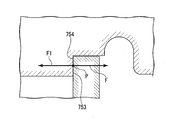
図7は、フック面753およびベース面754の模式拡大図である。牽引力Fは、板状部76を伝達してまずフック面753とベース面754との接触部位(すなわち、連結状態におけるフック70とベース20aとの接触部分)Pに作用し、フック面753に反力F1を生じさせる。
FIG. 7 is a schematic enlarged view of the hook surface 753 and the base surface 754. The traction force F is transmitted through the plate-like portion 76 and first acts on the contact portion P between the hook surface 753 and the base surface 754 (that is, the contact portion between the hook 70 and the base 20a in the connected state) P, and the pulling force F is applied to the hook surface 753. Force F1 is generated.
第一変形部752は、図9に示すように、接触部位Pと第二変形部762とを通る線である基線B1から離れた位置にあるため、反力F1は、爪部75に対してモーメントとして作用する。その結果、爪部75の先端部を、第一変形部752を中心として回動するように変形させる。図示していないが、爪部77にも反力F1と同様の力が作用する。その結果、爪部77の先端部は、第一変形部772を中心として回動するように変形する。
基線B1、B2が中心軸線X1と平行であるため、第二変形部762と接触部位P、および第二変形部782と接触部位Pは、中心軸線X1と平行に配置される。そのため、反力F1は第二変形部762、782に対してモーメントとして作用しない。 As shown in FIG. 9, since the firstdeformable portion 752 is located away from the base line B1 that is a line that passes through the contact portion P and the second deformable portion 762, the reaction force F1 is applied to the claw portion 75. Acts as a moment. As a result, the tip portion of the claw portion 75 is deformed so as to rotate about the first deformable portion 752. Although not shown, a force similar to the reaction force F1 also acts on the claw 77. As a result, the tip end portion of the claw portion 77 is deformed so as to rotate around the first deformable portion 772.
Since the base lines B1 and B2 are parallel to the central axis line X1, the seconddeformable portion 762 and the contact portion P, and the second deformable portion 782 and the contact portion P are arranged parallel to the central axis line X1. Therefore, the reaction force F1 does not act on the second deformable portions 762 and 782 as a moment.
基線B1、B2が中心軸線X1と平行であるため、第二変形部762と接触部位P、および第二変形部782と接触部位Pは、中心軸線X1と平行に配置される。そのため、反力F1は第二変形部762、782に対してモーメントとして作用しない。 As shown in FIG. 9, since the first
Since the base lines B1 and B2 are parallel to the central axis line X1, the second
図8に示すように、爪部75が第一変形部752を中心として変形した結果フック面753がベース面754に対して傾くと、反力F1に、中心軸線X1から押さえ管30の径方向外側に向かう方向の分力F2が生じる。
As shown in FIG. 8, when the hook surface 753 is tilted with respect to the base surface 754 as a result of the claw portion 75 deforming around the first deformable portion 752, the reaction force F1 causes the radial direction of the pressing tube 30 from the central axis line X1. A component force F2 in the outward direction is generated.
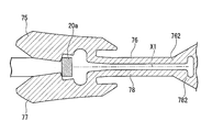
分力F2は、係合アーム73をベース20aから離間させる方向に作用する。すなわち、分力F2は、第二変形部762、782に対してモーメントとして作用する。このモーメントにより、板状部76、78はそれぞれ第二変形部762および782を中心として、互いの先端を離間させるように回動する。その結果、図11に示すように爪部75と爪部77とが大きく離間して、フック70とベース20aとの係合が解除される。
The component force F2 acts in the direction of separating the engagement arm 73 from the base 20a. That is, the component force F2 acts as a moment on the second deformable portions 762 and 782. This moment causes the plate-shaped portions 76 and 78 to rotate about the second deformable portions 762 and 782, respectively, so as to separate their tips from each other. As a result, as shown in FIG. 11, the claw portion 75 and the claw portion 77 are largely separated from each other, and the engagement between the hook 70 and the base 20a is released.
本実施形態のフック70において、第一変形部を中心とした爪部75、77の回動により分力F2が発生するまでは、牽引力Fの大きさに関わらず第二変形部を中心とした板状部76、78の回動は発生しない。したがって、第一変形部を中心とした爪部75、77の回動に必要な力量が、アームが硬い組織を挟んだ場合のロック力量より大きければ、第二変形部を中心とした板状部76、78の回動に必要な力量をアームが硬い組織を挟んだ場合のロック力量より小さく設定しても、ロック前にフック70とベース20aとの連結が解除されることはない。
In the hook 70 of this embodiment, until the component force F2 is generated by the rotation of the claws 75 and 77 centering on the first deformable portion, the second deforming portion is centered regardless of the magnitude of the traction force F. The plate- like portions 76 and 78 do not rotate. Therefore, if the amount of force required to rotate the claws 75 and 77 about the first deformed portion is larger than the amount of locking force when the arm sandwiches a hard tissue, the plate-shaped portion centered on the second deformed portion. Even if the amount of force required for rotating the arms 76 and 78 is set to be smaller than the amount of lock force when the arm sandwiches a hard tissue, the connection between the hook 70 and the base 20a is not released before locking.
フック70は上述の構造を有するため、第二変形部762、782を第一変形部752、772よりも変形しやすくすることにより、第二変形部を中心とした板状部76、78の回動に必要な力量を、ロック力量に対して著しく小さく設定できる。その結果、アームのロック後に爪部75、77にロック力量を超える力が作用した後は、速やかに板状部76、78が回動してフック70とベース20aとの連結が解除される。
Since the hook 70 has the above-described structure, the second deformable portions 762 and 782 are more easily deformed than the first deformable portions 752 and 772, so that the plate-shaped portions 76 and 78 having the second deformable portion as a center can rotate. The force required for movement can be set significantly smaller than the lock force. As a result, after a force exceeding the lock force is applied to the claws 75 and 77 after the arms are locked, the plate-shaped portions 76 and 78 are swung quickly to release the connection between the hook 70 and the base 20a.
これにより、結紮装置1においては、クリップユニット10をアプリケータ50から切り離す際に必要な操作力量が、クリップユニット10のアームのロック力量に対して過度に大きくなることを防止できる。その結果、硬い組織を挟んだ状態でクリップユニット10を留置することと、操作のしやすさとを両立できる。
With this, in the ligation device 1, it is possible to prevent the amount of operating force required for separating the clip unit 10 from the applicator 50 from becoming excessively large with respect to the amount of locking force of the arm of the clip unit 10. As a result, it is possible to achieve both indwelling of the clip unit 10 while sandwiching a hard tissue and ease of operation.
本実施形態では、初期状態においてフック面が中心軸線X1に対して垂直である例を示したが、フック面は、初期状態において中心軸線X1に対して垂直でなくてもよい。
In the present embodiment, an example is shown in which the hook surface is perpendicular to the central axis X1 in the initial state, but the hook surface may not be perpendicular to the central axis X1 in the initial state.
図12に示す変形例では、初期状態においてフック面753Aが中心軸線X1に対して基端側で鋭角θ1をなすように傾いている。その結果、フック面753Aとベース面754との接触部位P1が、図12に示す断面において第一実施形態の接触部位Pよりも中心軸線X1から離れた位置にある。さらに、中心軸線X1と接触部位P1との距離が、中心軸線X1と第二変形部762との距離よりも長くなり、基線B1が傾いて中心軸線X1と非平行となっている。
この変形例では、フック面753を備える第一実施形態よりも分力F2が発生するタイミングが早くなり、連結解除がスムーズになる。
図13に示す変形例では、初期状態においてフック面753Bが中心軸線X1に対して基端側で鈍角θ2をなすように傾いている。その結果、フック面753Bとベース面754との接触部位P2が、図13に示す断面において接触部位Pよりも中心軸X1に近い位置にある。さらに、中心軸線X1と接触部位P1との距離が、中心軸線X1と第二変形部762との距離よりも短くなり、基線B1が傾いて中心軸線X1と非平行となっている。この変形例では、フック面753を備える第一実施形態よりも分力F2が発生するタイミングが遅くなり、フック70とベース20aとの連結をより強固にできる。
以上説明したように、フック面とベース面との接触部位を変更することにより、連結解除の力量やタイミング等を様々に調節できる。接触部位を変更する手段は、上述したフック面と中心軸線X1とがなす角度を変更することには限られない。 In the modification shown in FIG. 12, in the initial state, thehook surface 753A is inclined so as to form an acute angle θ1 on the base end side with respect to the central axis X1. As a result, the contact portion P1 between the hook surface 753A and the base surface 754 is located farther from the central axis X1 than the contact portion P of the first embodiment in the cross section shown in FIG. Further, the distance between the central axis X1 and the contact portion P1 is longer than the distance between the central axis X1 and the second deformable portion 762, and the base line B1 is inclined and is not parallel to the central axis X1.
In this modified example, the timing at which the component force F2 is generated is earlier than that in the first embodiment including thehook surface 753, and the connection is released smoothly.
In the modified example shown in FIG. 13, thehook surface 753B is inclined so as to form an obtuse angle θ2 on the base end side with respect to the central axis X1 in the initial state. As a result, the contact portion P2 between the hook surface 753B and the base surface 754 is located closer to the central axis X1 than the contact portion P in the cross section shown in FIG. Further, the distance between the central axis X1 and the contact portion P1 is shorter than the distance between the central axis X1 and the second deformable portion 762, and the base line B1 is inclined and is not parallel to the central axis X1. In this modification, the timing at which the component force F2 is generated is delayed as compared with the first embodiment including the hook surface 753, and the connection between the hook 70 and the base 20a can be made stronger.
As described above, by changing the contact portion between the hook surface and the base surface, it is possible to variously adjust the amount and timing of disconnection. The means for changing the contact portion is not limited to changing the angle formed by the hook surface and the central axis X1 described above.
この変形例では、フック面753を備える第一実施形態よりも分力F2が発生するタイミングが早くなり、連結解除がスムーズになる。
図13に示す変形例では、初期状態においてフック面753Bが中心軸線X1に対して基端側で鈍角θ2をなすように傾いている。その結果、フック面753Bとベース面754との接触部位P2が、図13に示す断面において接触部位Pよりも中心軸X1に近い位置にある。さらに、中心軸線X1と接触部位P1との距離が、中心軸線X1と第二変形部762との距離よりも短くなり、基線B1が傾いて中心軸線X1と非平行となっている。この変形例では、フック面753を備える第一実施形態よりも分力F2が発生するタイミングが遅くなり、フック70とベース20aとの連結をより強固にできる。
以上説明したように、フック面とベース面との接触部位を変更することにより、連結解除の力量やタイミング等を様々に調節できる。接触部位を変更する手段は、上述したフック面と中心軸線X1とがなす角度を変更することには限られない。 In the modification shown in FIG. 12, in the initial state, the
In this modified example, the timing at which the component force F2 is generated is earlier than that in the first embodiment including the
In the modified example shown in FIG. 13, the
As described above, by changing the contact portion between the hook surface and the base surface, it is possible to variously adjust the amount and timing of disconnection. The means for changing the contact portion is not limited to changing the angle formed by the hook surface and the central axis X1 described above.
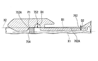
上述の例では、板状部76における接続部位T付近の部位を第二変形部としたが、第二変形部の位置はこれに限られない。上述したフックとリンクとの連結解除動作を実現するためには、牽引力Fによって第二変形部に生じるモーメントよりも大きいモーメントが第一変形部に生じる位置関係であればよい。言い換えると、図14に示すように、中心軸線X1と平行であり且つ接触部位Pを通る線X2と第一変形部752との距離D1が、線X2と第二変形部762との距離D2より長くなる位置であればよい。例えば、板状部76のうち接続部位Tよりも前方に位置する部分762Aも、第二変形部に該当する。本実施形態においては、板状部が中心軸線X1とほぼ平行に延びているため、板状部の任意の位置を第二変形部と考えることができる。
In the above example, the portion near the connection portion T in the plate-shaped portion 76 is the second deformed portion, but the position of the second deformed portion is not limited to this. In order to realize the above-mentioned operation of releasing the connection between the hook and the link, a positional relationship in which a moment larger than the moment generated in the second deformable portion by the traction force F is generated in the first deformable portion is sufficient. In other words, as shown in FIG. 14, the distance D1 between the first deformable portion 752 and the line X2 that is parallel to the central axis X1 and passes through the contact portion P is smaller than the distance D2 between the line X2 and the second deformable portion 762. It only needs to be in a long position. For example, the portion 762A of the plate-shaped portion 76 located in front of the connection site T also corresponds to the second deformation portion. In the present embodiment, since the plate-shaped portion extends substantially parallel to the central axis X1, any position of the plate-shaped portion can be considered as the second deformed portion.
第一変形部は、連結状態において基線から離れている限り、フックの中心軸線方向における位置に制限はない。例えば、第一変形部752が接触部位Pよりもフックの先端側に設けられてもよい。
図15に示す変形例では、中心軸線X1が延びる方向において、第一変形部752が第一実施形態よりも接触部位Pに近い位置に設けられている。このようにすると、爪部75に作用するモーメントが大きくなり、連結解除がスムーズになる。この効果を高めるためには、第一変形部752は、中心軸線X1が延びる方向において接触部位Pと同一の位置にあることが好ましい。 The position of the first deformable portion in the central axis direction of the hook is not limited as long as the first deformed portion is apart from the base line in the connected state. For example, the firstdeformable portion 752 may be provided closer to the tip end side of the hook than the contact portion P.
In the modification shown in FIG. 15, the firstdeformable portion 752 is provided at a position closer to the contact portion P than in the first embodiment in the direction in which the central axis X1 extends. By doing so, the moment acting on the claw portion 75 increases, and the connection is released smoothly. In order to enhance this effect, the first deformable portion 752 is preferably located at the same position as the contact portion P in the direction in which the central axis X1 extends.
図15に示す変形例では、中心軸線X1が延びる方向において、第一変形部752が第一実施形態よりも接触部位Pに近い位置に設けられている。このようにすると、爪部75に作用するモーメントが大きくなり、連結解除がスムーズになる。この効果を高めるためには、第一変形部752は、中心軸線X1が延びる方向において接触部位Pと同一の位置にあることが好ましい。 The position of the first deformable portion in the central axis direction of the hook is not limited as long as the first deformed portion is apart from the base line in the connected state. For example, the first
In the modification shown in FIG. 15, the first
本発明の第二実施形態について、図16から図19を参照して説明する。以降の説明において、すでに説明したものと共通する構成については、同一の符号を付して重複する説明を省略する。
A second embodiment of the present invention will be described with reference to FIGS. 16 to 19. In the following description, the same components as those already described will be designated by the same reference numerals and redundant description will be omitted.
図16に、本実施形態のクリップユニット110を示す。クリップユニット110は、アーム部120と、押さえ管30とを備えている。押さえ管30の内部の構造は、第一実施形態と同様である。
FIG. 16 shows the clip unit 110 of this embodiment. The clip unit 110 includes an arm portion 120 and a pressing tube 30. The internal structure of the presser tube 30 is similar to that of the first embodiment.
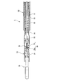
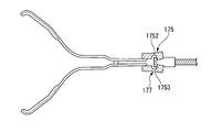
図17に、操作ワイヤ52とアーム部120との連結構造、すなわち本実施形態におけるリンクを示す。第一アーム121と第二アーム122とは、別々の部材であり、接合部123で接合されている。第一アーム121および第二アーム122は、接合部123よりも後方に延びている。接合部123の形成方法としては、溶接、半田、接着、ロウ付け等を例示できる。
FIG. 17 shows a connecting structure of the operation wire 52 and the arm part 120, that is, a link in the present embodiment. The first arm 121 and the second arm 122 are separate members and are joined at the joining portion 123. The first arm 121 and the second arm 122 extend rearward of the joint portion 123. Examples of the method of forming the joint portion 123 include welding, soldering, bonding, brazing and the like.
第一アーム121および第二アーム122の後端部には、それぞれ爪部材175、177が取り付けられている。爪部材175は、第一変形部1752およびフック面1753を有する。爪部材177は、第一変形部1772およびフック面1773を有する。
爪部材175、177は金属等で形成でき、第一アーム121や第二アーム122と同一材料で形成されてもよい。爪部材175、177は溶接、半田、接着、ロウ付け等により第一アーム121や第二アーム122に固定できる。 Claw members 175 and 177 are attached to the rear ends of the first arm 121 and the second arm 122, respectively. The claw member 175 has a first deformable portion 1752 and a hook surface 1753. The claw member 177 has a first deformable portion 1772 and a hook surface 1773.
The claw members 175 and 177 can be formed of metal or the like, and may be formed of the same material as the first arm 121 and the second arm 122. The claw members 175 and 177 can be fixed to the first arm 121 and the second arm 122 by welding, soldering, bonding, brazing, or the like.
爪部材175、177は金属等で形成でき、第一アーム121や第二アーム122と同一材料で形成されてもよい。爪部材175、177は溶接、半田、接着、ロウ付け等により第一アーム121や第二アーム122に固定できる。
The
操作ワイヤ52の先端には、ベース153が固定されている。ベース153の形状は、フック面1753およびフック面1773と係合できるベース面153aを有していれば特に制限はなく、ベース20aと同様の形状でもよい。
A base 153 is fixed to the tip of the operation wire 52. The shape of the base 153 is not particularly limited as long as it has the base surface 153a that can be engaged with the hook surface 1753 and the hook surface 1773, and may be the same shape as the base 20a.
本実施形態では、爪部材175、177がベース153を挟むことにより、操作ワイヤ52とクリップユニット120とが連結される。
操作ワイヤ52とアーム部120とが連結された図17の状態において、第一アーム121および第二アーム122の接合部123よりも後方の部分が板状部124および125として機能し、板状部124および125における接合部123付近の領域が、それぞれ第二変形部124aおよび125aとして機能する。
第一変形部1752は第一アーム121の基線B3に対して、第二変形部1772は第二アーム122の基線B4に対して、それぞれ離れた位置にある。
すなわち、本実施形態においては、クリップユニットがアーム部120の後端部にフック170を有し、操作ワイヤがベースを有している。 In the present embodiment, theoperating wire 52 and the clip unit 120 are connected by the claw members 175, 177 sandwiching the base 153.
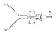
In the state of FIG. 17 in which theoperation wire 52 and the arm portion 120 are connected, the portions of the first arm 121 and the second arm 122 that are behind the joint portion 123 function as the plate-shaped portions 124 and 125, and the plate-shaped portions. Regions near the joint 123 in 124 and 125 function as second deforming portions 124a and 125a, respectively.
The firstdeformable portion 1752 and the second deformable portion 1772 are located away from the baseline B3 of the first arm 121 and the baseline B4 of the second arm 122, respectively.
That is, in this embodiment, the clip unit has thehook 170 at the rear end of the arm portion 120, and the operation wire has the base.
操作ワイヤ52とアーム部120とが連結された図17の状態において、第一アーム121および第二アーム122の接合部123よりも後方の部分が板状部124および125として機能し、板状部124および125における接合部123付近の領域が、それぞれ第二変形部124aおよび125aとして機能する。
第一変形部1752は第一アーム121の基線B3に対して、第二変形部1772は第二アーム122の基線B4に対して、それぞれ離れた位置にある。
すなわち、本実施形態においては、クリップユニットがアーム部120の後端部にフック170を有し、操作ワイヤがベースを有している。 In the present embodiment, the
In the state of FIG. 17 in which the
The first
That is, in this embodiment, the clip unit has the
本実施形態において、クリップユニットのアームがロックされた後は、図18に示すように、まずクリップユニットに設けられた爪部材175、177の後部が第一変形部1752、1753を中心に回動する。その後に、図19に示すように板状部124および125が第二変形部124aおよび125aを中心に回動して、クリップユニットと操作ワイヤとの連結が解除される。
In the present embodiment, after the arm of the clip unit is locked, as shown in FIG. 18, first, the rear portions of the claw members 175 and 177 provided on the clip unit rotate about the first deformable portions 1752 and 1753. To do. After that, as shown in FIG. 19, the plate-shaped portions 124 and 125 rotate around the second deformable portions 124a and 125a, and the connection between the clip unit and the operation wire is released.
本実施形態に係るクリップユニットおよび結紮装置も、第一実施形態と同様に、硬い組織を挟んだ状態でクリップユニットを留置することと、操作のしやすさとを両立できる。
本実施形態では、フック170がクリップユニットに設けられているため、フック170はクリップユニット120とともに体内に留置される。したがって、新しいクリップをアプリケータに装着して再度留置を行うリロードタイプの結紮装置に適用すると、フックが係合と連結を繰り返すことにより疲労破壊することがないという利点がある。 Similarly to the first embodiment, the clip unit and the ligation device according to the present embodiment can both make the clip unit indwelling while sandwiching a hard tissue and facilitate the operation.
In the present embodiment, since thehook 170 is provided in the clip unit, the hook 170 is left inside the body together with the clip unit 120. Therefore, when applied to a reload-type ligation device in which a new clip is attached to an applicator and is again indwelled, there is an advantage that the hook does not fatigue and fracture due to repeated engagement and connection.
本実施形態では、フック170がクリップユニットに設けられているため、フック170はクリップユニット120とともに体内に留置される。したがって、新しいクリップをアプリケータに装着して再度留置を行うリロードタイプの結紮装置に適用すると、フックが係合と連結を繰り返すことにより疲労破壊することがないという利点がある。 Similarly to the first embodiment, the clip unit and the ligation device according to the present embodiment can both make the clip unit indwelling while sandwiching a hard tissue and facilitate the operation.
In the present embodiment, since the
以上、本発明の各実施形態について説明したが、本発明の技術範囲は上記実施形態に限定されるものではなく、本発明の趣旨を逸脱しない範囲において各構成要素に種々の変更を加えたり、削除したりすることが可能である。
Although the respective embodiments of the present invention have been described above, the technical scope of the present invention is not limited to the above-mentioned embodiments, and various modifications are made to the respective components within a range not departing from the spirit of the present invention, It can be deleted.
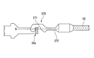
上述の各実施形態では、フックが一対の係合アームを有する例を説明したが、本発明におけるフックの態様はこれには限られない。
図20に、係合アームを一つのみ備えるフックの例を示す。図20に示すフック270は、一つの係合アーム271を有する。このような構造でも、第一変形部271、第二変形部272、接触部位P、および基線Bとの位置関係を適切に設定し、かつ第一変形部271および第二変形部272の曲げ剛性を適切に設定することにより、上述した各実施形態と同様の効果を奏することができる。 In each of the above-described embodiments, an example in which the hook has a pair of engaging arms has been described, but the aspect of the hook in the present invention is not limited to this.
FIG. 20 shows an example of a hook including only one engaging arm. Thehook 270 shown in FIG. 20 has one engagement arm 271. Even with such a structure, the positional relationship among the first deformable portion 271, the second deformable portion 272, the contact portion P, and the base line B is appropriately set, and the bending rigidity of the first deformable portion 271 and the second deformable portion 272 is set. By appropriately setting, it is possible to obtain the same effects as those of the above-described embodiments.
図20に、係合アームを一つのみ備えるフックの例を示す。図20に示すフック270は、一つの係合アーム271を有する。このような構造でも、第一変形部271、第二変形部272、接触部位P、および基線Bとの位置関係を適切に設定し、かつ第一変形部271および第二変形部272の曲げ剛性を適切に設定することにより、上述した各実施形態と同様の効果を奏することができる。 In each of the above-described embodiments, an example in which the hook has a pair of engaging arms has been described, but the aspect of the hook in the present invention is not limited to this.
FIG. 20 shows an example of a hook including only one engaging arm. The
また、各実施形態のいずれにおいても、第一変形部と第二変形部とを異なる材料で形成することにより両者の曲げ剛性を異ならせてもよい。また、第一変形部や第二変形部は、回動軸を有するヒンジ等の構造であってもよい。
Also, in any of the embodiments, the bending rigidity of the first deformed portion and the second deformed portion may be made different by forming them from different materials. Further, the first deformable portion and the second deformable portion may have a structure such as a hinge having a rotating shaft.
本発明における処置部は、上述したクリップユニットには限られない。例えば、図21に示す医療機器1Aのように、処置部90が一対のアームに代えてスネアループ91を有してもよい。
処置部90において、押さえ管30内部の構造は、クリップユニット10と概ね同様である。係止部23とスネアループ91との間には、円盤状の圧縮部材92が取り付けられている。操作ワイヤ52を後退させると、スネアループ91が押さえ管30内に引き込まれて縮小しつつ、圧縮部材92によってコイルバネ31が圧縮されるため、スネアループ91による緊縛のやり直しができる。係止部23を押さえ管30外に移動させると、スネアループ91が小さくなった状態でロックされる。リンク80の連結を解除すると処置部90をアプリケータ50から切り離せる。
この変形例において、スネアループ91のループ形状には特に制限はない。 The treatment portion in the present invention is not limited to the above-mentioned clip unit. For example, like themedical device 1A shown in FIG. 21, the treatment section 90 may have a snare loop 91 instead of the pair of arms.
In thetreatment portion 90, the internal structure of the presser tube 30 is substantially the same as that of the clip unit 10. A disk-shaped compression member 92 is attached between the locking portion 23 and the snare loop 91. When the operating wire 52 is retracted, the compression member 92 compresses the coil spring 31 while the snare loop 91 is drawn into the pressing tube 30 and contracts, so that the snare loop 91 can perform the binding again. When the locking portion 23 is moved to the outside of the holding tube 30, the snare loop 91 is locked in a small size. When the link 80 is released, the treatment section 90 can be separated from the applicator 50.
In this modification, the loop shape of thesnare loop 91 is not particularly limited.
処置部90において、押さえ管30内部の構造は、クリップユニット10と概ね同様である。係止部23とスネアループ91との間には、円盤状の圧縮部材92が取り付けられている。操作ワイヤ52を後退させると、スネアループ91が押さえ管30内に引き込まれて縮小しつつ、圧縮部材92によってコイルバネ31が圧縮されるため、スネアループ91による緊縛のやり直しができる。係止部23を押さえ管30外に移動させると、スネアループ91が小さくなった状態でロックされる。リンク80の連結を解除すると処置部90をアプリケータ50から切り離せる。
この変形例において、スネアループ91のループ形状には特に制限はない。 The treatment portion in the present invention is not limited to the above-mentioned clip unit. For example, like the
In the
In this modification, the loop shape of the
本発明は、処置部を切り離して使用する医療機器に適用することができる。
The present invention can be applied to a medical device in which a treatment section is separated and used.
1 結紮装置(医療機器)
10、110 クリップユニット(処置部)
20、120 アーム部
20a 基端部(ベース)
21、121 第一アーム
22、122 第二アーム
50 アプリケータ
52 操作ワイヤ(動力伝達部材)
70、170、270 フック
73、74 係合アーム
80 リンク
90 処置部
124a、125a 第二変形部
153 ベース
153a ベース面
271、271A 第一変形部
272 第二変形部
752、772 第一変形部
753、753A、753B、773 係合面(フック面)
754 ベース面
762、782 第二変形部
1752、1772 第一変形部
1753、1773 係合面(フック面)
B、B1、B2、B3、B4 基線
P、P1、P2 接触部位
X1 中心軸線(フックの) 1 Ligation device (medical equipment)
10,110 Clip unit (treatment part)
20, 120Arm portion 20a Base end portion (base)
21, 121 First arm 22, 122 Second arm 50 Applicator 52 Operation wire (power transmission member)
70, 170, 270 Hook 73, 74 Engaging arm 80 Link 90 Treatment portion 124a, 125a Second deforming portion 153 Base 153a Base surface 271, 271A First deforming portion 272 Second deforming portion 752, 772 First deforming portion 753, 753A, 753B, 773 Engaging surface (hook surface)
754 Base surface 762, 782 Second deformable portion 1752, 1772 First deformable portion 1753, 1773 Engaging surface (hook surface)
B, B1, B2, B3, B4 Base lines P, P1, P2 Contact area X1 Central axis (of hook)
10、110 クリップユニット(処置部)
20、120 アーム部
20a 基端部(ベース)
21、121 第一アーム
22、122 第二アーム
50 アプリケータ
52 操作ワイヤ(動力伝達部材)
70、170、270 フック
73、74 係合アーム
80 リンク
90 処置部
124a、125a 第二変形部
153 ベース
153a ベース面
271、271A 第一変形部
272 第二変形部
752、772 第一変形部
753、753A、753B、773 係合面(フック面)
754 ベース面
762、782 第二変形部
1752、1772 第一変形部
1753、1773 係合面(フック面)
B、B1、B2、B3、B4 基線
P、P1、P2 接触部位
X1 中心軸線(フックの) 1 Ligation device (medical equipment)
10,110 Clip unit (treatment part)
20, 120
21, 121
70, 170, 270
754
B, B1, B2, B3, B4 Base lines P, P1, P2 Contact area X1 Central axis (of hook)
Claims (15)
- 処置部と、
前記処置部を操作するための細長の動力伝達部材と、
前記動力伝達部材と前記処置部とを切り離し可能に連結するリンクと、
を備え、
前記リンクは、
前記動力伝達部材から受ける力で変形する第一変形部および第二変形部を有するフックと、
前記フックと係合可能なベースと、を有し、
前記動力伝達部材と前記処置部とが連結した連結状態において、前記第一変形部は、基線から離れた位置にあり、
前記基線は、前記連結状態における前記フックと前記ベースとの接触部分と、前記第二変形部とを通る線である、
医療機器。 A treatment section,
An elongated power transmission member for operating the treatment section,
A link that releasably connects the power transmission member and the treatment section;
Equipped with
The link is
A hook having a first deformable portion and a second deformable portion that are deformed by a force received from the power transmission member,
A base engageable with the hook,
In a connected state in which the power transmission member and the treatment section are connected, the first deformable section is located at a position away from a base line,
The base line is a line passing through a contact portion between the hook and the base in the connected state and the second deformable portion,
Medical equipment. - 前記連結状態において、前記第一変形部と前記接触部分との距離は、前記第二変形部と前記接触部分との距離よりも短い、
請求項1に記載の医療機器。 In the connected state, the distance between the first deformable portion and the contact portion is shorter than the distance between the second deformable portion and the contact portion,
The medical device according to claim 1. - 前記フックは、前記動力伝達部材の操作により前記基線に沿って移動するように構成されている、
請求項1に記載の医療機器。 The hook is configured to move along the base line by operating the power transmission member.
The medical device according to claim 1. - 前記フックは、フック面を有し、
前記ベースは、ベース面を有し、
前記連結状態において、前記ベース面は、前記フック面と前記第二変形部との間に位置して前記フック面と接触している、
請求項1に記載の医療機器。 The hook has a hook surface,
The base has a base surface,
In the connected state, the base surface is located between the hook surface and the second deformable portion and is in contact with the hook surface,
The medical device according to claim 1. - 前記フックの中心軸線と前記接触部位との距離は、前記中心軸線と前記第二変形部との距離よりも長い、
請求項1に記載の医療機器。 The distance between the central axis of the hook and the contact portion is longer than the distance between the central axis and the second deformable portion,
The medical device according to claim 1. - 前記フックの中心軸線と前記接触部位との距離は、前記中心軸線と前記第二変形部との距離よりも短い、
請求項1に記載の医療機器。 The distance between the central axis of the hook and the contact portion is shorter than the distance between the central axis and the second deformable portion,
The medical device according to claim 1. - 前記第一変形部の曲げ剛性は、前記第二変形部の曲げ剛性よりも高い、
請求項1に記載の医療機器。 The bending rigidity of the first deformable portion is higher than the bending rigidity of the second deformable portion,
The medical device according to claim 1. - 前記フックは、前記第一変形部、前記第二変形部、および前記フック面を有する係合アームを二つ有し、前記係合アームが前記フックの中心軸に対して対称に配置されている、
請求項4に記載の医療機器。 The hook has two engaging arms having the first deformable portion, the second deformable portion, and the hook surface, and the engaging arms are arranged symmetrically with respect to the central axis of the hook. ,
The medical device according to claim 4. - 前記動力伝達部材がワイヤである、
請求項1に記載の医療機器。 The power transmission member is a wire,
The medical device according to claim 1. - 前記処置部が前記ベースを有し、
前記動力伝達部材が前記フックを有する、
請求項1に記載の医療機器。 The treatment section has the base,
The power transmission member has the hook,
The medical device according to claim 1. - 前記処置部が前記フックを有し、
前記動力伝達部材が前記ベースを有する、
請求項1に記載の医療機器。 The treatment section has the hook,
The power transmission member has the base,
The medical device according to claim 1. - 前記第一変形部および前記第二変形部が同一の部材で形成されている、
請求項1に記載の医療機器。 The first deformable portion and the second deformable portion are formed of the same member,
The medical device according to claim 1. - 前記第一変形部と前記第二変形部とが異なる部材で形成されている、
請求項1に記載の医療機器。 The first deformable portion and the second deformable portion are formed of different members,
The medical device according to claim 1. - ベースを有する処置部が装着されるアプリケータであって、
前記処置部を操作するための細長の動力伝達部材と、
前記動力伝達部材と接続され、前記ベースと係合可能なフックと、
を備え、
前記フックは、前記動力伝達部材から受ける力で変形する第一変形部および第二変形部を有し、
前記フックと前記ベースとが連結した連結状態において、前記第一変形部は、基線から離れた位置にあり、
前記基線は、前記フックと前記ベースとの接触部分と前記第二変形部とを通る線である、
アプリケータ。 An applicator to which a treatment section having a base is attached,
An elongated power transmission member for operating the treatment section,
A hook connected to the power transmission member and engageable with the base;
Equipped with
The hook has a first deformable portion and a second deformable portion that are deformed by a force received from the power transmission member,
In the connected state in which the hook and the base are connected, the first deformable portion is at a position away from the base line,
The base line is a line passing through the contact portion between the hook and the base and the second deformable portion,
applicator. - 先端部にベースが設けられた動力伝達部材を備えるアプリケータに装着されるクリップユニットであって、
第一アームと、
第二アームと、
前記ベースに係合可能なフックと、
を備え、
前記フックは、前記動力伝達部材から伝達される力で変形する第一変形部および第二変形部を有し、
前記フックと前記ベースとが連結した連結状態において、前記第一変形部は、基線から離れた位置にあり、
前記基線は、前記フックと前記ベースとの接触部分と前記第二変形部とを通る線である、
クリップユニット。 A clip unit attached to an applicator including a power transmission member having a base provided at a tip end,
The first arm,
The second arm,
A hook engageable with the base,
Equipped with
The hook has a first deformable portion and a second deformable portion that are deformed by a force transmitted from the power transmission member,
In the connected state in which the hook and the base are connected, the first deformable portion is at a position away from the base line,
The base line is a line passing through the contact portion between the hook and the base and the second deformable portion,
Clip unit.
Priority Applications (6)
| Application Number | Priority Date | Filing Date | Title |
|---|---|---|---|
| PCT/JP2018/045450 WO2020121400A1 (en) | 2018-12-11 | 2018-12-11 | Medical device, applicator, and clip unit |
| CN201980081571.3A CN113194851A (en) | 2018-12-11 | 2019-12-11 | Medical device, feeder, and gripper unit |
| JP2020559285A JP7164626B2 (en) | 2018-12-11 | 2019-12-11 | Medical devices, applicators, clip units and methods of releasing clip units |
| CN202111504634.7A CN114305567A (en) | 2018-12-11 | 2019-12-11 | Medical device |
| PCT/JP2019/048489 WO2020122120A1 (en) | 2018-12-11 | 2019-12-11 | Medical device, applicator, and clip unit |
| US17/342,976 US20210290245A1 (en) | 2018-12-11 | 2021-06-09 | Medical device, applicator, and clip unit |
Applications Claiming Priority (1)
| Application Number | Priority Date | Filing Date | Title |
|---|---|---|---|
| PCT/JP2018/045450 WO2020121400A1 (en) | 2018-12-11 | 2018-12-11 | Medical device, applicator, and clip unit |
Publications (1)
| Publication Number | Publication Date |
|---|---|
| WO2020121400A1 true WO2020121400A1 (en) | 2020-06-18 |
Family
ID=71077149
Family Applications (2)
| Application Number | Title | Priority Date | Filing Date |
|---|---|---|---|
| PCT/JP2018/045450 WO2020121400A1 (en) | 2018-12-11 | 2018-12-11 | Medical device, applicator, and clip unit |
| PCT/JP2019/048489 WO2020122120A1 (en) | 2018-12-11 | 2019-12-11 | Medical device, applicator, and clip unit |
Family Applications After (1)
| Application Number | Title | Priority Date | Filing Date |
|---|---|---|---|
| PCT/JP2019/048489 WO2020122120A1 (en) | 2018-12-11 | 2019-12-11 | Medical device, applicator, and clip unit |
Country Status (4)
| Country | Link |
|---|---|
| US (1) | US20210290245A1 (en) |
| JP (1) | JP7164626B2 (en) |
| CN (2) | CN114305567A (en) |
| WO (2) | WO2020121400A1 (en) |
Families Citing this family (5)
| Publication number | Priority date | Publication date | Assignee | Title |
|---|---|---|---|---|
| CN215899794U (en) * | 2020-12-23 | 2022-02-25 | 奥林巴斯株式会社 | Clamp conveying device |
| US11937828B2 (en) | 2021-01-26 | 2024-03-26 | Olympus Medical Systems Corp. | Endoscope treatment device |
| US11944321B2 (en) | 2021-01-26 | 2024-04-02 | Olympus Medical Systems Corp. | Endoscopic treatment device |
| WO2022190160A1 (en) | 2021-03-08 | 2022-09-15 | オリンパスメディカルシステムズ株式会社 | Endoscopic treatment implement |
| WO2023028250A1 (en) | 2021-08-25 | 2023-03-02 | GastroLogic LLC | Endoscopic clip apparatus and methods |
Citations (2)
| Publication number | Priority date | Publication date | Assignee | Title |
|---|---|---|---|---|
| JP2002191609A (en) * | 2000-10-16 | 2002-07-09 | Olympus Optical Co Ltd | Clip apparatus for anatomy |
| JP2009125548A (en) * | 2007-11-28 | 2009-06-11 | Sumitomo Bakelite Co Ltd | Clip, clip unit and clip device |
Family Cites Families (15)
| Publication number | Priority date | Publication date | Assignee | Title |
|---|---|---|---|---|
| US20020138086A1 (en) * | 2000-12-06 | 2002-09-26 | Robert Sixto | Surgical clips particularly useful in the endoluminal treatment of gastroesophageal reflux disease (GERD) |
| US20020068945A1 (en) * | 2000-12-06 | 2002-06-06 | Robert Sixto | Surgical clips particularly useful in the endoluminal treatment of gastroesophageal reflux disease (GERD) |
| JP5448533B2 (en) * | 2009-03-31 | 2014-03-19 | テルモ株式会社 | In vivo tissue closure device |
| KR101159422B1 (en) * | 2009-12-22 | 2012-06-28 | 국립암센터 | Surgical indicator clip and clip apparatus |
| JP5588711B2 (en) * | 2010-03-30 | 2014-09-10 | 富士フイルム株式会社 | Ligation device |
| US9078666B2 (en) * | 2010-04-02 | 2015-07-14 | Olympus Medical Systems Corp. | Medical device |
| AU2011316687B2 (en) * | 2010-10-11 | 2014-10-30 | Cook Medical Technologies Llc | Medical devices with detachable pivotable jaws |
| JP2013063106A (en) * | 2011-09-15 | 2013-04-11 | Fujifilm Corp | Medical treatment instrument |
| EP2875787B1 (en) * | 2012-07-20 | 2018-02-21 | Olympus Corporation | Hemostatic clip |
| US9358021B2 (en) * | 2013-01-09 | 2016-06-07 | Covidien Lp | Connection of an endovascular intervention device to a manipulation member |
| WO2014181678A1 (en) * | 2013-05-07 | 2014-11-13 | オリンパスメディカルシステムズ株式会社 | Endoscopic treatment instrument |
| JP6716453B2 (en) * | 2014-03-31 | 2020-07-01 | 日本ゼオン株式会社 | Endoscopic treatment tool |
| EP3366236B1 (en) * | 2015-10-23 | 2021-10-13 | Hangzhou Ags Medtech Co., Ltd. | Ligation device |
| AU2017333663B2 (en) * | 2016-09-29 | 2019-11-21 | Boston Scientific Limited | Sacrificial coupler for reloadable hemostasis clipping device |
| CN109788955B (en) * | 2016-12-28 | 2021-08-17 | 株式会社钟化 | Medical clamp box |
-
2018
- 2018-12-11 WO PCT/JP2018/045450 patent/WO2020121400A1/en active Application Filing
-
2019
- 2019-12-11 CN CN202111504634.7A patent/CN114305567A/en active Pending
- 2019-12-11 CN CN201980081571.3A patent/CN113194851A/en active Pending
- 2019-12-11 WO PCT/JP2019/048489 patent/WO2020122120A1/en active Application Filing
- 2019-12-11 JP JP2020559285A patent/JP7164626B2/en active Active
-
2021
- 2021-06-09 US US17/342,976 patent/US20210290245A1/en active Pending
Patent Citations (2)
| Publication number | Priority date | Publication date | Assignee | Title |
|---|---|---|---|---|
| JP2002191609A (en) * | 2000-10-16 | 2002-07-09 | Olympus Optical Co Ltd | Clip apparatus for anatomy |
| JP2009125548A (en) * | 2007-11-28 | 2009-06-11 | Sumitomo Bakelite Co Ltd | Clip, clip unit and clip device |
Also Published As
| Publication number | Publication date |
|---|---|
| WO2020122120A1 (en) | 2020-06-18 |
| JPWO2020122120A1 (en) | 2021-10-28 |
| CN113194851A (en) | 2021-07-30 |
| CN114305567A (en) | 2022-04-12 |
| JP7164626B2 (en) | 2022-11-01 |
| US20210290245A1 (en) | 2021-09-23 |
Similar Documents
| Publication | Publication Date | Title |
|---|---|---|
| WO2020121400A1 (en) | Medical device, applicator, and clip unit | |
| EP2042109A1 (en) | Clip applier | |
| CN103930054A (en) | Automatic surgical ligation clip applier | |
| JP5486983B2 (en) | Ligation device | |
| WO2013040467A2 (en) | Manual surgical ligation clip applier | |
| JP2013521877A (en) | Narrow contour surgical ligation clip | |
| CN114469238A (en) | Endoscope clamp | |
| WO2020095427A1 (en) | Endoscope clip | |
| WO2016185965A1 (en) | Clip device | |
| WO2012039163A1 (en) | Ligature device and clip unit used therein | |
| US9867624B2 (en) | Endoscopic treatment instrument | |
| US20210290240A1 (en) | Medical device and method of releasing clip unit | |
| CN110769765B (en) | Clamp treatment tool | |
| CN217938300U (en) | A treatment device and clamping device for endoscope for ligature living body tissue | |
| WO2021084728A1 (en) | Medical device | |
| CN112955081A (en) | Endoscope clamp | |
| WO2021156930A1 (en) | Applicator and ligation device | |
| CN217066505U (en) | Medical device | |
| CN113365565A (en) | Clip box, medical apparatus, and method of mounting medical apparatus | |
| JP7328385B2 (en) | Endoscopic treatment tool and clip unit | |
| US20220370073A1 (en) | Cartridge and coupling member detaching method |
Legal Events
| Date | Code | Title | Description |
|---|---|---|---|
| 121 | Ep: the epo has been informed by wipo that ep was designated in this application |
Ref document number: 18943275 Country of ref document: EP Kind code of ref document: A1 |
|
| NENP | Non-entry into the national phase |
Ref country code: DE |
|
| 122 | Ep: pct application non-entry in european phase |
Ref document number: 18943275 Country of ref document: EP Kind code of ref document: A1 |
|
| NENP | Non-entry into the national phase |
Ref country code: JP |