WO2020116451A1 - 画像処理装置、学習装置、画像処理方法、学習方法、及びプログラム - Google Patents
画像処理装置、学習装置、画像処理方法、学習方法、及びプログラム Download PDFInfo
- Publication number
- WO2020116451A1 WO2020116451A1 PCT/JP2019/047240 JP2019047240W WO2020116451A1 WO 2020116451 A1 WO2020116451 A1 WO 2020116451A1 JP 2019047240 W JP2019047240 W JP 2019047240W WO 2020116451 A1 WO2020116451 A1 WO 2020116451A1
- Authority
- WO
- WIPO (PCT)
- Prior art keywords
- image
- learning
- image processing
- unit
- conversion
- Prior art date
- Legal status (The legal status is an assumption and is not a legal conclusion. Google has not performed a legal analysis and makes no representation as to the accuracy of the status listed.)
- Ceased
Links
Images






Classifications
-
- H—ELECTRICITY
- H04—ELECTRIC COMMUNICATION TECHNIQUE
- H04N—PICTORIAL COMMUNICATION, e.g. TELEVISION
- H04N19/00—Methods or arrangements for coding, decoding, compressing or decompressing digital video signals
- H04N19/10—Methods or arrangements for coding, decoding, compressing or decompressing digital video signals using adaptive coding
- H04N19/134—Methods or arrangements for coding, decoding, compressing or decompressing digital video signals using adaptive coding characterised by the element, parameter or criterion affecting or controlling the adaptive coding
- H04N19/154—Measured or subjectively estimated visual quality after decoding, e.g. measurement of distortion
-
- H—ELECTRICITY
- H04—ELECTRIC COMMUNICATION TECHNIQUE
- H04N—PICTORIAL COMMUNICATION, e.g. TELEVISION
- H04N19/00—Methods or arrangements for coding, decoding, compressing or decompressing digital video signals
- H04N19/85—Methods or arrangements for coding, decoding, compressing or decompressing digital video signals using pre-processing or post-processing specially adapted for video compression
-
- G—PHYSICS
- G06—COMPUTING OR CALCULATING; COUNTING
- G06N—COMPUTING ARRANGEMENTS BASED ON SPECIFIC COMPUTATIONAL MODELS
- G06N3/00—Computing arrangements based on biological models
- G06N3/02—Neural networks
- G06N3/08—Learning methods
- G06N3/084—Backpropagation, e.g. using gradient descent
-
- G—PHYSICS
- G06—COMPUTING OR CALCULATING; COUNTING
- G06T—IMAGE DATA PROCESSING OR GENERATION, IN GENERAL
- G06T7/00—Image analysis
-
- H—ELECTRICITY
- H04—ELECTRIC COMMUNICATION TECHNIQUE
- H04N—PICTORIAL COMMUNICATION, e.g. TELEVISION
- H04N1/00—Scanning, transmission or reproduction of documents or the like, e.g. facsimile transmission; Details thereof
- H04N1/41—Bandwidth or redundancy reduction
-
- H—ELECTRICITY
- H04—ELECTRIC COMMUNICATION TECHNIQUE
- H04N—PICTORIAL COMMUNICATION, e.g. TELEVISION
- H04N19/00—Methods or arrangements for coding, decoding, compressing or decompressing digital video signals
- H04N19/10—Methods or arrangements for coding, decoding, compressing or decompressing digital video signals using adaptive coding
- H04N19/134—Methods or arrangements for coding, decoding, compressing or decompressing digital video signals using adaptive coding characterised by the element, parameter or criterion affecting or controlling the adaptive coding
- H04N19/136—Incoming video signal characteristics or properties
-
- H—ELECTRICITY
- H04—ELECTRIC COMMUNICATION TECHNIQUE
- H04N—PICTORIAL COMMUNICATION, e.g. TELEVISION
- H04N19/00—Methods or arrangements for coding, decoding, compressing or decompressing digital video signals
- H04N19/80—Details of filtering operations specially adapted for video compression, e.g. for pixel interpolation
Definitions
- the present invention relates to an image processing device, a learning device, an image processing method, a learning method, and a program.
- an imaging device for capturing an image to be processed exists in an environment in which it communicates with an edge server of a communication network, and a server responsible for automating a visual inspection process is an imaging device.
- a server responsible for automating a visual inspection process is an imaging device.
- the captured image is transmitted to the cloud server via the edge server. In this case, it is required to reduce the code amount during transmission while maintaining the image processing accuracy.
- Image coding methods that reduce the code amount during transmission while maintaining image processing accuracy are roughly divided into two methods: a method of transmitting an image itself and a method of transmitting information indicating characteristics extracted from the image.
- Examples of the former method of transmitting the image itself include H.264.
- There is a general image coding method such as H.265/HEVC (High Efficiency Video Coding).
- examples of the latter method of transmitting information indicating characteristics extracted from an image include, for example, a method called Collaborative Intelligence, in which a characteristic map that is an output of an intermediate layer of a neural network is transmitted (for example, Non-Patent Document 1).
- the latter method is efficient in terms of power consumption and calculation time, but it is difficult to restore the original image from the feature quantity, for example, especially when the hierarchy of the neural network that extracts the feature map is deep. (See Non-Patent Document 1).
- a general image encoding method is a method mainly for maintaining image quality. Therefore, in a general image coding method, in order to maintain the image quality in a low code amount band, a process of actively thinning out high frequency components that are difficult for humans to perceive is performed, and signals in the low frequency region are retained preferentially. To be done. As a result, in such a general image encoding method, when the image processing is performed on the original image and the decoded image, the image processing accuracy is lower when the image processing is performed on the decoded image. I have something to do.
- Non-Patent Document 2 shows that when a perturbation that humans hardly recognize the difference is given to an image, the processing accuracy of image processing by a convolutional neural network may be significantly reduced. That is, it can be said that the signal that holds the image quality and the signal that holds the image processing accuracy do not always match.
- Non-Patent Document 3 which describes the relationship between the code amount and the image identification accuracy in JPEG (Joint Photographic Experts Group) and JPEG2000, the image identification accuracy in the low code amount band is lower than that in the high code amount band. Have been shown to be significant. Considering these points, it can be said that the general image encoding method is insufficient as a method for maintaining the image processing accuracy.
- Non-Patent Document 4 As a prior art in which an image coding method is examined from the viewpoint of maintaining image processing accuracy, there is a technology described in Non-Patent Document 4, for example.
- the technique described in Non-Patent Document 4 is based on image processing accuracy by generating an importance map in an image from a reaction of a feature map of a convolutional neural network and assigning a code amount to an important image region with emphasis. Allows rate control.
- the technique described in Non-Patent Document 4 is based on H.264. The rate is controlled by HM which is the H.265/HEVC reference software, and the quantized parameters (QP) obtained there are corrected within a range of about ⁇ 2 to 3. Therefore, it can be said that significant reduction in coding efficiency cannot be expected.
- HM is the H.265/HEVC reference software
- Non-Patent Document 4 is not supposed to be applied to an encoding method in which a quantization parameter cannot be changed in an image, such as JPEG. Therefore, the technique described in Non-Patent Document 4 is difficult to apply to a coding system that does not include an adaptive quantization mechanism.
- an image pickup device that picks up an image does not necessarily include an encoding system including an adaptive quantization mechanism, it is desirable to use an image encoding method that does not depend on the encoding method in the subsequent stage.
- JPEG has a mechanism for storing a quantization table in the header, it is possible to introduce an adaptive quantization mechanism into JPEG, strictly speaking.
- a quantization table is assigned to each coded block, it is expected that the total code amount will increase due to an increase in calculation amount and a huge header, so it is not possible to introduce an adaptive quantization mechanism into JPEG. It can be said that it is not realistic.
- an image pre-filter (pre-conversion) (for example, Non-Patent Document 5).
- the pre-filter method smoothes a part or the whole of the image before the encoding process to reduce the code amount of the image.
- Non-Patent Document 5 describes an image coding method in which a region in which it is difficult for humans to perceive changes is calculated based on human perceptual characteristics, and the smoothing strength is determined. Generally, when an image is smoothed, high frequency components are reduced, and a prediction residual is reduced in the predictive coding method. Thereby, the smoothing by the pre-filter method can convert an image into a state in which the code amount is low, without depending on the image coding method.
- H.264 In addition to H.265/HEVC, Even in H.264/AVC (Advanced Video Coding), the effectiveness of the code amount reduction by the image pre-filter is shown.
- the image coding method described in Non-Patent Document 5 is based on human perception characteristics and is not a method that considers image processing accuracy.
- an image conversion technique that converts an image with a low code amount while maintaining image processing accuracy and also holds inspection accuracy of a visual inspection by a human (hereinafter, referred to as “visual accuracy”).
- visual accuracy a method of smoothing image components, which is widely known for its effect of reducing the code amount, is considered to be promising. Further, if the image components are uniformly smoothed, the image processing accuracy is reduced (Non-Patent Document 3), but it is expected that the processing accuracy will not be reduced if only the areas that are not important in the image processing are smoothed.
- the pre-filter method in consideration of image processing accuracy, it is unclear as to what kind of feature amount is emphasized in image processing. In other words, it can be said that it is unclear as to which region in the image should be converted into the image so as to be smoothed. Therefore, the pre-filter method has a problem that it is difficult to design a filter based on physiological knowledge such as human perception characteristics.
- Non-Patent Document 4 a method of smoothing the image component by utilizing the generated importance map can be considered.
- this method in order to perform the image conversion that does not affect the image processing accuracy, in what degree should the smoothing process be performed using the importance map in the first place? It is unclear.
- the importance map generated by the technique described in Non-Patent Document 4 is generated according to the output strength of the intermediate layer of CNN (Convolutional Neural Network). Therefore, the map does not show a truly important area in that the smoothing process does not affect the image processing accuracy.
- the present invention has been made in view of the technical background as described above, and provides an image conversion technique that reduces the code amount while maintaining the image processing accuracy, and also holds the human visual accuracy.
- the purpose is to
- One aspect of the present invention includes an image processing unit that executes image processing on an image based on an input image and outputs a result of the image processing, and the input image is an image converted from an original image.
- the image processing is a post-conversion image
- the image conversion is an image conversion in which the feature amount used in the image processing is held and the data size of the original image is reduced while maintaining the processing accuracy of the image processing. It is a device.
- one aspect of the present invention is the above-described image processing device, wherein the image conversion is image conversion that further maintains visual accuracy between the original image and the converted image. ..
- an aspect of the present invention is the above-described image processing apparatus, further comprising an image correction unit that obtains a corrected image by correcting the contrast of the image based on the input image using a predetermined correction coefficient, The image processing unit executes the image processing on the corrected image.
- machine learning is performed using a learning image indicating a learning image and information indicating a result of image conversion for the learning image, so that a predetermined condition is satisfied for the original image.
- a learning unit that acquires a learning result for obtaining a converted image that has been subjected to image conversion so as to satisfy the predetermined condition holds a feature amount used for image processing, and maintains processing accuracy of the image processing.
- the learning device includes a condition that the data size of the original image is made smaller.
- the predetermined condition further includes a condition that visual accuracy between the original image and the converted image is maintained.
- one aspect of the present invention includes an image processing step of performing image processing on an image based on an input image and outputting a result of the image processing, wherein the input image is an image converted from an original image.
- the image conversion method is an image conversion after the conversion, in which the image conversion is an image conversion that reduces the data size of the original image while maintaining the characteristics used in the image processing and the processing accuracy of the image processing. Is.
- machine learning is performed using a learning image indicating a learning image and information indicating a result of image conversion for the learning image, so that a predetermined condition is satisfied for the original image.
- a learning step of acquiring a learning result for obtaining a converted image that has been subjected to image conversion so as to satisfy, and the predetermined condition holds a feature amount used for image processing, and improves the processing accuracy of the image processing.
- This is a learning method including a condition that the data size of the original image is made smaller while being held.
- one aspect of the present invention is a program for causing a computer to function as the above-described image processing apparatus.
- the code amount can be reduced while maintaining the image processing accuracy.
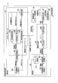
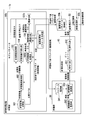
- FIG. 1 is a block diagram showing the functional arrangement of an image processing apparatus 1 according to the first embodiment of the present invention.
- the image processing device 1 includes a learning unit 10, an image processing parameter storage unit 20, an inference unit 30, an image transmission unit 40, an image correction unit 50, and an image processing unit 60. It is configured to include.
- the learned model that has been machine-learned (hereinafter referred to as “learning”) by the learning unit 10 is used by the inference unit 30 in the subsequent stage. Therefore, there is a time difference between the timing at which the learning unit 10 performs the processing and the timing at which the functional units subsequent to the inference unit 30 in the subsequent stage perform the processing.
- the learning unit 10 includes a learning image storage unit 101, a learning image conversion unit 102, a visual accuracy holding unit 103, a learning image smoothing unit 104, a learning image processing unit 105, and an optimization unit.
- the unit 107 is included.
- the learning image storage unit 101 stores in advance an image for learning (hereinafter referred to as “learning image”) and correct answer data in image processing (hereinafter referred to as “correct answer label”).
- learning image an image for learning
- correct answer label Is, for example, flash memory, HDD (Hard Disk Drive), SDD (Solid State Drive), RAM (Random Access Memory; readable/writable memory), EEPROM (Electrically Erasable Programmable Read Only Memory), registers, and ROM (Read Only) It is realized by a storage medium such as a memory (read-only memory) or a combination of these storage media.
- the learning image conversion unit 102 acquires a learning image from the learning image storage unit 101.
- the learning image conversion unit 102 also acquires from the optimization unit 107 the model parameters updated by the optimization unit 107 (hereinafter referred to as “updated model parameters”).
- the learning image conversion unit 102 performs image conversion on the acquired learning image based on the acquired updated model parameter.
- the learning image conversion unit 102 outputs the image-converted learning image (hereinafter, referred to as “converted learning image”) to the visual accuracy holding unit 103, the learning image smoothing unit 104, and the learning image processing unit 105. Further, the learning image conversion unit 102 outputs the model parameter used for the image conversion to the optimization unit 107.
- the visual accuracy holding unit 103 acquires the converted learning image output from the learning image conversion unit 102.
- the visual accuracy holding unit 103 evaluates the visual accuracy, which is the inspection accuracy of the visual inspection by humans, on the acquired learning image after conversion, and calculates the visual accuracy loss for increasing the visual accuracy.
- the visual accuracy holding unit 103 outputs the calculated visual accuracy loss to the optimizing unit 107.
- the learning image smoothing unit 104 acquires the converted learning image output from the learning image converting unit 102.
- the learning image smoothing unit 104 evaluates the degree of smoothing of the image of the acquired learning image after conversion, and calculates the image smoothing loss for increasing the degree of smoothing.
- the learning image smoothing unit 104 outputs the calculated image smoothing loss to the optimization unit 107.
- the learning image smoothing unit 104 may calculate an image smoothing loss for reducing the smoothing degree depending on the distance between the image processing result and the correct label, for example.
- the learning image processing unit 105 acquires a correct answer label from the learning image storage unit 101. Further, the learning image processing unit 105 acquires the parameter of the image processing model (hereinafter, referred to as “image processing parameter”) from the image processing parameter storage unit 20. The learning image processing unit 105 also acquires the converted learning image output from the learning image converting unit 102. The learning image processing unit 105 performs image processing on the acquired post-conversion learning image to calculate an image processing loss for minimizing the difference from the correct label. The learning image processing unit 105 propagates the calculated image processing loss to the input unit of the image processing model and outputs it to the optimization unit 107.
- the term “propagation” refers to a process of calculating an error gradient at a desired position of an image conversion model according to an error gradient calculation algorithm such as an error back propagation method.
- the optimization unit 107 acquires the visual accuracy loss output from the visual accuracy holding unit 103. Further, the optimization unit 107 acquires the image smoothing loss output from the learning image smoothing unit 104. Further, the optimization unit 107 acquires the image processing loss output from the learning image processing unit 105. Further, the optimization unit 107 acquires the model parameter output from the learning image conversion unit 102. The optimization unit 107 updates the acquired model parameters so as to optimize the acquired visual accuracy loss, the image smoothing loss, and the image processing loss. That is, the optimization unit 107 updates the model parameter so that the distance between the image processing result and the correct answer label is shortened as much as possible while the visual accuracy and the image smoothing degree are set as high as possible.
- the optimization unit 107 When continuing learning, the optimization unit 107 outputs the updated model parameter (hereinafter, referred to as “updated model parameter”) to the learning image conversion unit 102. On the other hand, when finishing the learning, the optimization unit 107 stores the updated model parameter (hereinafter, referred to as “parameter after learning”) in the parameter storage unit 301.
- the learning image conversion unit 102 does not perform image conversion of the entire original image, but performs image conversion only on a desired target range for which visual inspection is to be performed, and converts each loss (particularly from the learning image after conversion corresponding to the range).
- the visual accuracy loss may be calculated.
- the image processing parameter storage unit 20 stores in advance image processing parameters that are parameters for image processing.
- the image processing parameter storage unit 20 is realized, for example, by a storage medium such as a flash memory, an HDD, an SDD, a RAM, an EEPROM, a register, a ROM, or a combination of these storage media.
- the inference unit 30 includes a parameter storage unit 301, an inference image acquisition unit 302, and an inference image conversion unit 303.
- the parameter storage unit 301 stores the post-learning parameters output from the optimization unit 107.
- the parameter storage unit 301 is realized by, for example, a storage medium such as a flash memory, an HDD, an SDD, a RAM, an EEPROM, and a register, or a combination of these storage media.
- the inference image acquisition unit 302 acquires an image to be image-processed (hereinafter referred to as “inference image”) from, for example, an external imaging device or a storage medium.
- the inference image acquisition unit 302 may have a function as an imaging device.
- the inference image acquisition unit 302 outputs the acquired inference image to the inference image conversion unit 303.
- the inference image conversion unit 303 acquires the inference image output from the inference image acquisition unit 302. Further, the inference image conversion unit 303 acquires the post-learning parameters from the parameter storage unit 301. The inference image conversion unit 303 performs image conversion on the acquired inference image based on the acquired post-learning parameters. The inference image conversion unit 303 outputs the image-converted inference image (hereinafter, referred to as “conversion inference image”) to the image transmission unit 40.
- conversion inference image the image-converted inference image
- the image transmission unit 40 includes an encoding unit 401 and a decoding unit 402.
- the encoding unit 401 acquires the post-conversion inference image output from the inference image conversion unit 303.
- the encoding unit 401 converts the acquired inferred image after conversion into, for example, H.264. It is converted into a bitstream by an existing encoding method such as H.265/HEVC.
- the encoding unit 401 transmits the converted bitstream to the decoding unit 402.
- the decoding unit 402 receives the bitstream transmitted from the encoding unit 401.
- the decoding unit 402 adds, for example, H.264 to the received bitstream.
- Decoding is performed by an existing encoding method such as H.265/HEVC. Thereby, the decoding unit 402 obtains a decoded image.
- the decoding unit 402 outputs the decoded image to the image correction unit 50.
- the post-conversion inference image is output to the encoding unit 401 for encoding, and the decoding unit 402 performs decoding.
- the configuration is not mandatory. This is because the post-conversion inference image retains the information necessary for the desired image processing, retains the visual accuracy, and is even better than the input inference image even if it is not encoded. This is because the data size is already small.
- the lossless coding (reversible coding) method may be used as the coding method used in the coding unit 401.
- unnecessary information such as several pixels at the edge of the image may be removed from the inferred image after conversion.
- it is effective in the case where an object to be image-processed appears in the central portion of the image.
- an image having a small original data size can be set as an encoding target image, and thus the target code amount set in the encoding unit 401 is easily reached.
- the image correction unit 50 acquires the decoded image output from the decoding unit 402.
- the image correction unit 50 performs a correction process on the acquired decoded image so as to improve the image processing accuracy.
- the image correction unit 50 outputs the decoded image subjected to the correction processing (hereinafter, referred to as “correction image”) to the image processing unit 60.
- the image processing unit 60 acquires image processing parameters from the image processing parameter storage unit 20. Further, the image processing unit 60 acquires the corrected image output from the image correction unit 50. The image processing unit 60 performs image processing on the acquired corrected image based on the acquired image processing parameter. Thereby, the image processing unit 60 obtains the image processing result. The image processing unit 60 outputs information indicating the image processing result to, for example, an external device.
- the learning image conversion unit 102 and the inference image conversion unit 303 are separate functional units in the present embodiment, they may be configured as one functional unit that operates during learning and during inference. Good.
- the learning image processing unit 105 and the image processing unit 60 are separate functional units, but they are configured as one functional unit that operates during learning and inference. Good.
- the present embodiment shows a method in which learning about visual accuracy loss is treated as prior learning of image smoothing loss and image processing loss. This method can be applied when learning using visual accuracy loss contributes to the improvement of image processing accuracy (for example, pre-learning with a mean square error (MSE)).
- MSE mean square error
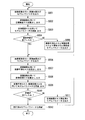
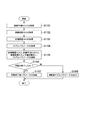
- FIG. 2 is a flowchart showing an example of the operation of the learning unit 10 according to the first embodiment of the present invention.
- the learning image conversion unit 102 of the learning unit 10 acquires a learning image from the learning image storage unit 101.
- the learning image conversion unit 102 also acquires the updated model parameters from the optimization unit 107.
- the learning image conversion unit 102 performs image conversion on the acquired learning image based on the acquired updated model parameter.
- the learning image conversion unit 102 outputs the converted learning image to the visual accuracy holding unit 103. Further, the learning image conversion unit 102 outputs the model parameter to the optimization unit 107 (step S001).
- the visual accuracy holding unit 103 of the learning unit 10 acquires the post-conversion learning image output from the learning image converting unit 102.
- the visual accuracy holding unit 103 evaluates the visual accuracy of the acquired learning image after conversion, and calculates the visual accuracy loss for increasing the visual accuracy.
- the visual accuracy holding unit 103 outputs the calculated visual accuracy loss to the optimizing unit 107 (step S002).
- the optimization unit 107 of the learning unit 10 acquires the visual accuracy loss output from the visual accuracy holding unit 103. Further, the optimization unit 107 acquires the model parameter output from the learning image conversion unit 102. The optimization unit 107 updates the model parameter based on the acquired visual accuracy loss. The optimization unit 107 outputs the updated model parameters to the learning image conversion unit 102 (step S003).
- step S004 when the pre-learning is not finished (No in step S004), the optimization unit 107 outputs the updated model parameter updated based on the image smoothing loss and the image processing loss to the learning image conversion unit 102. Yes (step S005). Then, the processing after step S001 is repeated.
- the learning image conversion unit 102 performs image conversion of the acquired learning image based on the acquired updated model parameter.
- the learning image converting unit 102 outputs the converted learning image to the learning image smoothing unit 104 and the learning image processing unit 105.
- the learning image conversion unit 102 also outputs the model parameter to the optimization unit 107 (step S006).
- the learning image smoothing unit 104 of the learning unit 10 acquires the converted learning image output from the learning image converting unit 102.
- the learning image smoothing unit 104 evaluates the degree of smoothing of the acquired learning image after conversion and calculates an image smoothing loss.
- the learning image smoothing unit 104 outputs the calculated image smoothing loss to the optimization unit 107 (step S007).
- the learning image processing unit 105 of the learning unit 10 acquires the correct answer label from the learning image storage unit 101. Further, the learning image processing unit 105 acquires image processing parameters from the image processing parameter storage unit 20. The learning image processing unit 105 also acquires the converted learning image output from the learning image converting unit 102. The learning image processing unit 105 performs image processing on the acquired post-learning learning image and calculates an image processing loss. The learning image processing unit 105 outputs the calculated image processing loss to the optimization unit 107 (step S008).
- the optimization unit 107 acquires the image smoothing loss output from the learning image smoothing unit 104. Further, the optimization unit 107 acquires the image processing loss output from the learning image processing unit 105. Further, the optimization unit 107 acquires the model parameter output from the learning image conversion unit 102. The optimization unit 107 updates the model parameters based on the acquired image smoothing loss and image processing loss (step S009).
- step S010 if the learning is not completed (step S010, No), the optimization unit 107 outputs the updated model parameter updated based on the visual accuracy loss to the learning image conversion unit 102 (step S011). Then, the processing after step S006 is repeated.
- step S010 Yes
- the optimization unit 107 stores the parameters after the learning in the parameter storage unit 301.
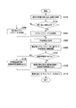
- FIG. 3 is a flowchart showing an example of the operation of the learning image conversion unit 102 according to the first embodiment of the present invention.
- the learning image conversion unit 102 acquires information indicating the current number of times learning is repeated (that is, the number of times learning has been repeated up to that point) (step S101).
- the information indicating the current number of repetitions of learning is assumed to be stored in, for example, a storage medium included in the learning unit 10.
- the learning image conversion unit 102 determines whether or not learning has started. That is, the learning image conversion unit 102 determines whether or not the number of learning times based on the acquired information is 0 (step S102). When the learning count is 0 (step S102, Yes), the learning image conversion unit 102 initializes model parameters (step S103).
- the learning image conversion unit 102 may be configured to initialize model parameters with a random value based on Gaussian distribution, which is generally used, or an image conversion model based on learning performed in advance.
- the configuration may be such that the model parameters are initialized by performing Fine-tuning using the model parameters of. Note that the term "fine-tuning" used here means that the parameters obtained by learning the image conversion model in advance using different data sets are used as initial values.
- step S102 when the learning count is not 0 (that is, 1 or more) (step S102, No), the learning image conversion unit 102 causes the optimization unit 107 to update the updated model parameters (that is, the image conversion model being learned). A model parameter) is acquired (step S104).
- the learning image conversion unit 102 acquires a learning image from the learning image storage unit 101 (step S105).
- the learning image conversion unit 102 performs image conversion on the acquired learning image based on the acquired updated model parameter (step S106). As a result, the learning image conversion unit 102 obtains the converted learning image.
- the image conversion used here includes, for example, non-linear conversion using a neural network.
- the learning image conversion unit 102 determines whether it is during pre-learning (step S107). In the case of pre-learning (step S107, Yes), the learning image conversion unit 102 outputs the converted learning image to the visual accuracy holding unit 103 (step S108). On the other hand, when it is not during pre-learning (that is, when it is during learning) (step S107, No), the learning image conversion unit 102 transfers the converted learning image to the learning image smoothing unit 104 and the learning image processing unit 195. Output (step S109).
- the learning image conversion unit 102 outputs the model parameter used for the above image conversion to the optimization unit 107 (step S110). With the above, the operation of the learning image converting unit 102 in the flowchart of FIG. 3 is completed.
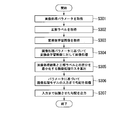
- FIG. 4 is a flowchart showing an example of the operation of the visual accuracy holding unit 103 according to the first embodiment of the present invention.
- the visual accuracy holding unit 103 acquires the post-conversion learning image (here, the post-conversion learning image Y′) output from the learning image converting unit 102 (step S201).
- the visual accuracy holding unit 103 evaluates the visual accuracy of the post-conversion learning image Y'using a predefined function (step S202).
- the visual accuracy loss does not have to be based on the mean square error or SSIM. If the function for evaluating the visual accuracy is an objective function that outputs an image processing result having a correlation with the image processing result when a human performs image processing by visual inspection, the same effect is obtained.
- the visual-accuracy holding unit 103 calculates a visual-accuracy loss (gradient) for increasing the visual accuracy of a human based on the above-described function for evaluating the visual accuracy.
- the visual accuracy holding unit 103 outputs the calculated visual accuracy loss to the optimizing unit 107.
- FIG. 5 is a flowchart showing an example of the operation of the learning image processing unit 105 according to the first embodiment of the present invention.
- the learning image processing unit 105 acquires image processing parameters from the image processing parameter storage unit 20 (step S301).
- the learning image processing unit 105 acquires a correct answer label indicating correct answer data in the image processing from the learning image storage unit 101 (step S302).
- the correct answer data is, for example, a vector string indicating whether or not each object is included in the case of identifying a subject in the image. It is an array or the like indicating to which region each pixel inside belongs.
- the learning image processing unit 105 acquires the converted learning image Y′ output from the learning image converting unit 102 (step S303).
- the learning image processing unit 105 performs image processing on the acquired post-conversion learning image Y′ based on the acquired image processing parameters (step S304). As a result, the learning image processing unit 105 obtains the image processing result (here, the image processing result x).
- the image processing referred to here includes, for example, image processing such as object identification using a neural network, object detection, and area division.
- the learning image processing unit 105 performs image processing on the acquired post-conversion learning image Y′ to minimize the difference between the image processing result x and the correct label (here, the correct label y).
- image processing loss (gradient) is calculated (step S305).
- image processing loss for example, cross entropy L cross_entropy represented by the following formula (1) is generally used.
- the image processing loss is not limited to the cross entropy as described above. If the function for calculating the image processing loss is an appropriate objective function for a desired image processing task, even if it is, for example, a mean square error, the same effect can be obtained.
- the calculated image processing loss gives a loss to the image conversion model. Therefore, the learning image processing unit 105 propagates the gradient (error) to the processing unit corresponding to the input unit of the image processing model (that is, the output unit of the image conversion model). At this time, the model parameters of the image conversion model are not updated.
- the learning image processing unit 105 outputs the gradient (image processing loss) propagated to the processing unit corresponding to the input unit of the image processing model to the optimization unit 107.
- the operation of the learning image processing unit 105 shown in the flowchart of FIG. 5 is completed.
- FIG. 6 is a flowchart showing an example of the operation of the learning image smoothing unit 104 according to the first embodiment of the present invention.
- the learning image smoothing unit 104 acquires the converted learning image Y′ output from the learning image converting unit 102 (step S401).
- the learning image smoothing unit 104 evaluates the spatial redundancy and the smoothing degree of the transformed learning image using a predefined function (step S402).
- a function for evaluating the spatial redundancy and the smoothing degree for example, an image smoothing loss L TV (Y′) represented by the following equation (2) based on Total Variation can be given.
- the image smoothing loss is not limited to the function based on Total Variation. If the function for calculating the image smoothing loss is an objective function that takes spatial redundancy into consideration, the same effect is obtained.
- the learning image smoothing unit 104 calculates a gradient for increasing the spatial redundancy and the degree of smoothing based on the function (for example, Expression (2)) used for the evaluation in step S402.
- the learning image smoothing unit 104 outputs the calculated gradient (image smoothing loss) to the optimization unit 107 (step S403).
- FIG. 7 is a flowchart showing an example of the operation of the optimizing unit 107 according to the first embodiment of the present invention.
- the optimization unit 107 determines whether or not it is during pre-learning (step S501). In the case of pre-learning (step S501, Yes), the optimization unit 107 acquires the visual accuracy loss output from the visual accuracy holding unit 103 (step S502). Further, the optimization unit 107 acquires the model parameter output from the learning image conversion unit 102 (step S503). The optimization unit 107 updates the acquired model parameter using the acquired visual accuracy loss (step S504). Then, the optimization unit 107 outputs the updated model parameter to the learning image conversion unit 102 (step S511).
- the optimization unit 107 acquires the image smoothing loss output from the learning image smoothing unit 104 (step S505). .. Further, the optimization unit 107 acquires the image processing loss output from the learning image processing unit 105 (step S506). Further, the optimization unit 107 acquires the model parameter output from the learning image conversion unit 102 (step S507).
- the optimization unit 107 linearly combines the image smoothing loss and the image processing loss with a connection weight ⁇ cross_entropy' ⁇ TV , and updates the model parameter (step S508).
- the coupling load may be, for example, about 1:1 so that the image smoothing loss and the image processing loss are evaluated equally.
- the present invention is not limited to such a predetermined ratio, and the same effect can be obtained, for example, by manually adjusting while observing the transition of the entire loss function.
- SGD Stochastic Gradient Descent
- Stochastic Gradient Descent Stochastic Gradient Descent
- Adam which is one of the gradient descent optimization algorithms
- the present invention is not limited to this, and another optimization algorithm such as the Newton method may be used.
- the optimization unit 107 determines whether or not learning has been completed in this repetition (step S509).
- the determination of the end of learning may be made based on whether or not a predetermined number of times of learning has been reached, or may be made manually based on, for example, the transition of the loss function.
- the optimization unit 107 stores the post-learning parameters in the parameter storage unit 301.
- the optimization unit 107 outputs the updated model parameter to the learning image conversion unit 102 (step S511). This completes the operation of the optimizing unit 107 shown in the flowchart of FIG. 7.
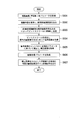
- FIG. 8 is a flowchart showing the operation of the functional units other than the learning unit 10 according to the first embodiment of the present invention.
- the inference image acquisition unit 302 of the inference unit 30 acquires the inference image.
- the inference image acquisition unit 302 outputs the acquired inference image to the inference image conversion unit 303.
- the inference image conversion unit 303 output from the inference image acquisition unit 302 acquires the inference image. Further, the inference image conversion unit 303 acquires the post-learning parameters from the parameter storage unit 301 (step S601).
- the inference image conversion unit 303 performs image conversion on the acquired inference image based on the acquired post-learning parameters.
- the inference image conversion unit 303 outputs the converted inference image after the image conversion to the image transmission unit 40 (step S602).
- the encoding unit 401 of the image transmission unit 40 acquires the converted inference image output from the inference image conversion unit 303.
- the encoding unit 401 converts the acquired inferred image after conversion into, for example, H.264. It is converted into a bitstream by encoding with an existing encoding method such as H.265/HEVC.
- the encoding unit 401 transmits the converted bitstream to the decoding unit 402 of the image transmission unit 40 (step S603).
- the decoding unit 402 receives the bitstream transmitted from the encoding unit 401.
- the decoding unit 402 adds, for example, H.264 to the received bitstream.
- Decoding is performed using an existing encoding method such as H.265/HEVC. Thereby, the decoding unit 402 obtains the decoded image (step S604).
- the decoding unit 402 outputs the decoded image to the image correction unit 50.
- the image correction unit 50 acquires the decoded image output from the image correction unit 50.
- the image correction unit 50 performs a gamma correction process on the acquired decoded image as a correction process for improving the image processing accuracy, for example, based on a predetermined correction parameter (correction coefficient) for the contrast of the decoded image. ..
- the image correction section 50 obtains a corrected image (step S605).
- the image correction unit 50 outputs the corrected image to the image processing unit 60.
- the purpose of performing the above correction processing is to correct the phenomenon that the contrast of the image decreases as a side effect of smoothing during image conversion.
- it is not limited to the correction processing for gamma-correcting the contrast. Even if the correction process is, for example, a process of normalizing the pixel value histogram, the same effect is obtained. It is assumed here that the contrast correction is performed by the gamma correction with the fixed parameter, but the correction parameter may be calculated and transmitted for each image.
- the image processing unit 60 acquires the same image processing parameter as the model parameter of the image processing conversion model used in the learning unit 10 from the image processing parameter storage unit 20 (step S606). Further, the image processing unit 60 acquires the corrected image output from the image correction unit 50. The image processing unit 60 performs image processing on the acquired corrected image based on the acquired image processing parameter. Thereby, the image processing unit 60 obtains the image processing result. The image processing unit 60 outputs information indicating the image processing result to, for example, an external device or the like (step S607). With the above, the operation of the flowchart of FIG. 8 by the functional units other than the learning unit 10 is completed.
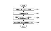
- FIG. 9 is a flowchart showing an example of the operation of the inference image conversion unit 303 according to the first embodiment of the present invention.
- the inference image conversion unit 303 acquires the post-learning parameters from the parameter storage unit 301 (step S701). Further, the inference image conversion unit 303 acquires the inference image output from the inference image acquisition unit 302 (step S702). The inference image conversion unit 303 image-converts the acquired inference image based on the acquired post-learning parameters (step S703). Thereby, the inference image conversion unit 303 obtains the converted inference image.
- the image conversion used here includes, for example, non-linear conversion using a neural network.
- the inference image conversion unit 303 outputs the converted inference image after the image conversion to the image transmission unit 40 (step S704). This is the end of the operation of the inference image conversion unit 303 shown in the flowchart of FIG.
- FIG. 10 is a flowchart showing an example of the operation of the image processing unit 60 according to the first embodiment of the present invention.
- the image processing unit 60 acquires image processing parameters from the image processing parameter storage unit 20 (step S801). Further, the image processing unit 60 acquires the corrected image output from the image correction unit 50 (step S802). The image processing unit 60 performs image processing on the acquired corrected image based on the acquired image processing parameter (step S803). Thereby, the image processing unit 60 obtains the image processing result.
- the image processing referred to here includes, for example, image processing such as object identification using a neural network, object detection, and area division.
- the image processing unit 60 outputs information indicating the image processing result to, for example, an external device or the like (step S804).
- the image processing model is included in the learning target
- the number of parameters to be learned increases as compared with the former method. Therefore, the time required for learning becomes long and the number of data necessary for converging learning increases.
- the latter method has an advantage that the image processing model can be trained so as to fit the converted image.
- FIG. 11 is a block diagram showing the functional arrangement of an image processing apparatus 1b according to the second embodiment of the present invention.
- the functional configuration of the image processing apparatus 1b according to the second embodiment differs from the functional configuration of the image processing apparatus 1 according to the first embodiment described above in that the image processing optimizing unit 106. And an image processing parameter storage unit 108.
- the image processing optimization unit 106 optimizes the parameters of the image processing model.
- the optimization unit 107b optimizes the parameters of the image processing model using the propagated image processing loss calculated by the image processing optimization unit 106 and the image smoothing loss.
- the same reference numerals are given to the functional units having the same functions as those in the first embodiment, and the description of the functional units will be omitted.
- FIG. 12 is a flowchart showing an example of the operation of the learning image processing unit 105b according to the second embodiment of the present invention.
- the learning image processing unit 105b acquires information indicating the current number of times learning is repeated (that is, the number of times learning has been repeated up to that point) (step S901). Note that the information indicating the current number of times the learning is repeated is assumed to be stored in, for example, a storage medium included in the learning unit 10b.
- the learning image processing unit 105b determines whether or not learning has started. That is, the learning image processing unit 105b determines whether the number of times of learning based on the acquired information is 0 (step S902). When the learning count is 0 (step S902, Yes), the learning image processing unit 105b initializes the parameters of the learning processing model (step S903).
- the learning image processing unit 105b may be configured to initialize parameters by a random value based on Gaussian distribution, which is generally used, or an image processing model based on learning performed in advance.
- the configuration may be such that the parameters are initialized by performing Fine-tuning using the parameters.
- the learning image processing unit 105b acquires the parameters of the learning processing model from the image processing parameter storage unit 108 (step S904). ).
- the learning image processing unit 105b acquires the correct answer label indicating the correct answer data in the image processing from the learning image storage unit 101 (step S905).
- the correct data is, for example, a vector string indicating whether or not each object is captured in the case of identifying the subject in the image, and in the case of performing the area division of the image. Is, for example, an array indicating which region each pixel in the image belongs to.
- the learning image processing unit 105b acquires the post-conversion learning image (here, referred to as the post-conversion learning image Y′) output from the learning image converting unit 102 (step S906).
- the learning image processing unit 105b performs image processing on the acquired converted learning image based on the parameters of the acquired learning processing model (step S907). As a result, the learning image processing unit 105b obtains the image processing result (here, the image processing result x).
- the learning image processing unit 105b performs image processing on the acquired post-conversion learning image Y′ to minimize the difference between the image processing result x and the correct label (here, the correct label y).
- image processing loss (gradient) is calculated (step S908).
- the image processing loss for example, the cross entropy L cross_entropy represented by the above formula (1) is generally used. However, the image processing loss is not limited to the cross entropy as in the expression (1). If the function for calculating the image processing loss is an appropriate objective function for a desired image processing task, even if it is, for example, a mean square error, the same effect can be obtained.
- the learning image processing unit 105b outputs the calculated image processing loss to the image processing optimization unit 106 (step S909). At this time, the obtained image processing loss is not propagated to the input unit of the learning processing model. Thus, the operation of the learning image processing unit 105b shown in the flowchart of FIG. 12 is completed.
- FIG. 13 is a flowchart showing an example of the operation of the image processing optimizing unit 106 according to the second embodiment of the present invention.
- the image processing optimization unit 106 acquires the image processing loss output from the learning image processing unit 105b (step S1001). The image processing optimization unit 106 also acquires the parameters of the image processing model from the image processing parameter storage unit 108 (step S1002). The image processing optimization unit 106 updates the parameters of the acquired image processing model using the acquired image processing loss (step S1003).
- the image processing optimization unit 106 outputs the gradient propagated to the input unit of the image processing model when updating the parameters of the image processing model to the optimization unit 107b as a propagated image processing loss (step S1004).
- the image processing optimization unit 106 determines whether or not learning has been completed in this repetition (step S1005).
- the determination of the end of learning may be made based on whether or not a predetermined number of times of learning has been reached, or may be made manually based on, for example, the transition of the loss function.
- step S1005 When it is determined that the learning is completed (step S1005, Yes), the image processing optimization unit 106 stores the updated parameters of the learning processing model in the image processing parameter storage unit 20b (step S1006). On the other hand, when it is determined that the learning has not ended (step S1005, No), the image processing optimization unit 106 stores the updated parameters of the learning processing model in the image processing parameter storage unit 108 (step S1007). ). With the above, the operation of the flowchart of FIG. 13 by the image processing optimizing unit 106 ends.
- the process after the process of the inference unit 30 in the latter stage is the same as the process in the first embodiment described above. That is, in the image processing apparatus 1b, the inference image conversion unit 303 performs image conversion, the image transmission unit 40 performs encoding processing and decoding processing according to a general encoding method, and the image correction unit 50 performs image contrast. Make a correction. Then, the image processing apparatus 1b performs image processing based on the parameters of the image processing model acquired from the image processing parameter storage unit 20b by the image processing unit 60, and outputs the image processing result.
- the first embodiment shows a method in which learning about visual accuracy loss is treated as prior learning of image smoothing loss and image processing loss.
- the third embodiment shows a method of learning all of the visual accuracy loss, the image smoothing loss, and the image processing loss at the same time.
- the latter method in which all three losses are learned at the same time, can learn all the losses at the same time, and therefore has the advantage of being able to further reduce the number of iterations in learning compared to the former method.
- the method of the third embodiment described below can be applied when the visual accuracy loss and the image processing loss are in conflict (for example, when the visual accuracy loss decreases, the image processing loss increases). Is. When the visual accuracy loss and the image processing loss are contradictory, the visual conversion loss and the image processing loss are learned at the same time to realize the image conversion so as to take a trade-off between the visual accuracy loss and the image processing loss. be able to.
- the optimizing unit performs the learning process by the latter method will be described with reference to the drawings.
- the overall configuration diagram of the image processing apparatus according to the third embodiment is the overall configuration diagram of the image processing apparatus 1 according to the first embodiment shown in FIG. 1 or the second embodiment shown in FIG. It is the same as the overall configuration diagram of the image processing apparatus 1 according to the present invention. However, the processing of the optimizing unit is different from that of the first and second embodiments.
- FIG. 14 is a flowchart showing an example of the operation of the optimizing unit according to the third embodiment of the present invention.
- the flowchart shown in FIG. 14 is an optimization unit (hereinafter, “optimization unit 107c”) in the case of optimizing all three losses at the same time in the configuration of the image processing apparatus 1 according to the first embodiment shown in FIG. That is)).
- the optimization unit 107c acquires the image smoothing loss output from the learning image smoothing unit 104 (step S1101). Further, the optimization unit 107c acquires the image processing loss output from the learning image processing unit 105 (step S1102). The optimization unit 107c acquires the visual accuracy loss output from the visual accuracy holding unit 103 (step S1103). In addition, the optimization unit 107c acquires the model parameter output from the learning image conversion unit 102 (step S1104).
- Optimization unit 107c includes a visual loss of precision, and image smoothing loss, and an image processing loss linear combination in connection weights ⁇ visual ' ⁇ cross_entropy' ⁇ TV , to update the model parameters (step S1105).
- the coupling load for example, a ratio of about 1:1:1 which evaluates all losses equally can be considered.
- the present invention is not limited to such a predetermined ratio, and the same effect can be obtained, for example, by manually adjusting while observing the transition of the entire loss function.
- SGD stocastic gradient descent method
- Adam which is one of the optimization algorithms of the gradient descent method
- the present invention is not limited to this, and another optimization algorithm such as the Newton method may be used.
- the optimization unit 107c determines whether or not learning has been completed in this repetition (step S1106).
- the determination of the end of learning may be made based on whether or not a predetermined number of times of learning has been reached, or may be made manually based on, for example, the transition of the loss function.
- step S1106, Yes When it is determined that the learning is completed (step S1106, Yes), the optimization unit 107c stores the parameter after the learning is completed in the parameter storage unit 301 (step S51107). On the other hand, when it is determined that the learning is not completed (step S1106, No), the optimization unit 107c outputs the updated model parameter to the learning image conversion unit 102 (step S51108). With the above, the operation of the flowchart of FIG. 14 by the optimizing unit 107c ends.
- the image processing apparatus 1 (or the image processing apparatus 1b) according to the above-described embodiment performs the image processing on the image (decoded image) based on the input image (original image), and the image processing is performed.
- an image processing unit 60 for outputting the result of the above, the input image is an image based on a post-conversion inference image (post-conversion image) obtained by performing image conversion on the original image, and the image conversion is the image processing. It is an image conversion that reduces the data size of the original image while maintaining the feature amount used for the above and the processing accuracy of the image processing.
- the image processing device 1 (or the image processing device 1b) according to the above-described embodiment can perform object identification, object detection, area division, etc. without depending on the encoding system in the subsequent stage. With respect to the image processing, it is possible to reduce the code amount when the image is encoded without lowering the image processing accuracy. Furthermore, according to the image processing device 1 (or the image processing device 1b) according to the above-described embodiment, it is possible to maintain the visual accuracy, which is the inspection accuracy when a human visually inspects. As a result, the image processing device 1 (or the image processing device 1b) can perform image transmission with a low code amount. As a secondary effect, the automation of the visual inspection process utilizing the image processing system can be industrially applied.
- the program executed in the above-described mode does not depend on a single device, but the program is recorded on a computer-readable recording medium and is recorded on this recording medium.
- the program may be read and executed by a computer system.
- the “computer system” mentioned here includes an OS and hardware such as peripheral devices.
- the “computer system” also includes a WWW system having a homepage providing environment (or display environment).
- the "computer-readable recording medium” refers to a portable medium such as a flexible disk, a magneto-optical disk, a ROM, a CD-ROM, or a storage device such as a hard disk built in a computer system.
- the "computer-readable recording medium” means a volatile memory (RAM) inside a computer system that serves as a server or a client when a program is transmitted via a network such as the Internet or a communication line such as a telephone line. As such, the one that holds the program for a certain period of time is also included.
- RAM volatile memory
- the above program may be transmitted from a computer system that stores the program in a storage device or the like to another computer system via a transmission medium or by a transmission wave in the transmission medium.
- the "transmission medium” for transmitting the program refers to a medium having a function of transmitting information such as a network (communication network) such as the Internet or a communication line (communication line) such as a telephone line.
- the program may be for realizing a part of the functions described above. Further, it may be a so-called difference file (difference program) that can realize the above-mentioned functions in combination with a program already recorded in the computer system.
Landscapes
- Engineering & Computer Science (AREA)
- Signal Processing (AREA)
- Multimedia (AREA)
- Physics & Mathematics (AREA)
- Theoretical Computer Science (AREA)
- General Physics & Mathematics (AREA)
- Biophysics (AREA)
- Mathematical Physics (AREA)
- Data Mining & Analysis (AREA)
- Evolutionary Computation (AREA)
- General Health & Medical Sciences (AREA)
- Molecular Biology (AREA)
- Computing Systems (AREA)
- General Engineering & Computer Science (AREA)
- Biomedical Technology (AREA)
- Computational Linguistics (AREA)
- Software Systems (AREA)
- Artificial Intelligence (AREA)
- Life Sciences & Earth Sciences (AREA)
- Health & Medical Sciences (AREA)
- Computer Vision & Pattern Recognition (AREA)
- Image Analysis (AREA)
- Compression Or Coding Systems Of Tv Signals (AREA)
- Compression Of Band Width Or Redundancy In Fax (AREA)
Abstract
画像処理装置は、入力画像に基づく画像に対して画像処理を実行し、前記画像処理の結果を出力する画像処理部を備え、前記入力画像は、原画像に対して画像変換がなされた変換後画像であり、前記変換は、前記画像処理に用いられる特徴及び前記画像処理の処理精度を保持しつつ、前記原画像のデータサイズをより小さくする画像変換である。
Description
本発明は、画像処理装置、学習装置、画像処理方法、学習方法、及びプログラムに関する。
近年、例えば、画像内の被写体の検出や識別、及び画像の領域分割等のための、機械学習を用いた画像処理の処理精度の向上が著しい。このような機械学習を用いた画像処理技術は、各種業務における目視検査工程を自動化する技術として注目を集めている。このような画像処理において、例えば、処理対象となる画像を撮像するための撮像デバイスが通信網のエッジサーバと通信する環境に存在し、かつ、目視検査工程の自動化を担うサーバが撮像デバイスとは物理的に遠い位置にあるクラウド環境に存在する場合、撮像された画像はエッジサーバを介してクラウドサーバに伝送される。この場合、画像処理精度を保持しつつ、伝送時の符号量を削減することが求められる。
画像処理精度を保持しつつ伝送時の符号量を削減する画像符号化方式には、大別して、画像そのものを伝送する方式と、画像から抽出した特徴を示す情報を伝送する方式との2つの方式がある。画像そのものを伝送する前者の方式としては、例えば、H.265/HEVC(High Efficiency Video Coding)等の一般的な画像符号化方式がある。一方、画像から抽出した特徴を示す情報を伝送する後者の方式としては、例えば、ニューラルネットワークの中間層の出力である特徴マップを伝送する、Collaborative Intelligenceと呼ばれる方式等がある(例えば、非特許文献1)。後者の方式は、消費電力や計算時間の面では効率的である一方で、例えば、特に特徴マップを抽出するニューラルネットワークの階層が深い場合等においては、特徴量から原画像を復元することが難しいことがある(非特許文献1参照)。
また、各種業務における全ての目視検査工程を画像処理システムによって自動化することは困難である。そのため、目視検査工程全体の流れとしては、まず画像処理システムを活用して一次スクリーニングが行われ、次に人間が直接目視検査して二次スクリーニングが行われる工程になることが想定される。このようなことから、目視検査工程を自動化するための画像符号化方式としては、処理対象の画像を人間が直接目視検査できる方式が用いられることが望ましい。
ところで、例えばH.265/HEVC等の一般的な画像符号化方式では、画像処理精度は評価指標とされておらず、主に客観画質及び主観画質が評価指標とされている。したがって、一般的な画像符号化方式は、主に画質を保持することを目的とした方式であると言える。そのため、一般的な画像符号化方式では、低符号量帯において、画質を保持するため、人間が感知しづらい高周波成分を積極的に間引く処理が行われ、低周波領域の信号が優先的に保持される。これにより、このような一般的な画像符号化方式では、原画像と復号画像とを対象として画像処理を行った場合、復号画像を対象として画像処理を行った場合の方が画像処理精度が低下することがある。
また、非特許文献2には、人間では違いをほとんど認知できないような摂動を画像に付与すると、畳み込みニューラルネットワークによる画像処理の処理精度が著しく低下することがあることが示されている。すなわち、画質を保持する信号と画像処理精度を保持する信号とは、必ずしも一致しないことがあると言える。さらに、JPEG(Joint Photographic Experts Group)及びJPEG2000における符号量と画像識別精度との関係について記載された非特許文献3には、高符号量帯と比べて、低符号量帯において画像識別精度の低下が著しいことが示されている。これらの点を鑑みても、一般的な画像符号化方式は、画像処理精度を保持するための方式としては不十分であると言える。
画像処理精度を保持するという観点で画像符号化方式を検討した先行技術としては、例えば、非特許文献4に記載の技術がある。非特許文献4に記載の技術は、畳み込みニューラルネットワークの特徴マップの反応から画像内の重要度マップを生成して、重要な画像領域に重点的に符号量を割り当てることで、画像処理精度に基づくレート制御を可能にする。しかしながら、非特許文献4に記載の技術は、H.265/HEVC参照ソフトウェアであるHMによってレート制御を行い、そこで得られた量子化パラメータ(QP;Quantization Parameters)を±2~3程度の範囲で修正するものである。そのため、大幅な符号化効率の削減は望めないと言える。さらに、非特許文献4に記載の技術は、例えばJPEGのように、画像内で量子化パラメータを変動させることができない符号化方式への適用については想定をしていない。そのため、非特許文献4に記載の技術は、適応量子化機構を備えない符号化システムに対しては適用が困難である。
また、画像を撮像する撮像デバイスに、適応量子化機構を備える符号化システムが必ずしも搭載されているとは限らないため、後段の符号化方式に依存しない画像符号化方式が用いられることが望ましい。なお、JPEGは量子化テーブルをヘッダに格納する機構になっているため、厳密に言えばJPEGに適応量子化機構を導入することも可能である。
しかしながら、各符号化ブロックに量子化テーブルを割り当てた場合、計算量の増加、及びヘッダの巨大化によって全体符号量が増大することが想定されるため、JPEGに適応量子化機構を導入することは現実的ではないと言える。
しかしながら、各符号化ブロックに量子化テーブルを割り当てた場合、計算量の増加、及びヘッダの巨大化によって全体符号量が増大することが想定されるため、JPEGに適応量子化機構を導入することは現実的ではないと言える。
後段の符号化方式に依存することなく、符号量を大幅に削減することができる画像符号化方式として、例えば、画像のプレフィルタ(プレ変換)と呼ばれる方式がある(例えば、非特許文献5)。プレフィルタ方式は、符号化処理の前に、画像の一部又は全体を平滑化し、画像の符号量を低下させる。
また、非特許文献5には、人間の知覚特性に基づいて人間が変化を知覚しにくい領域を算出して、平滑化の強度を決定する画像符号化方式が記載されている。一般に、画像が平滑化すると、高周波成分が削減され、予測符号化方式においては予測残差が小さくなる。
これにより、プレフィルタ方式による平滑化は、画像符号化方式に依存することなく、画像を符号量の低い状態に変換させることができる。実際に、非特許文献5では、H.265/HEVC以外に、H.264/AVC(Advanced Video Coding)においても、画像のプレフィルタによる符号量削減の有効性が示されている。しかしながら、非特許文献5に記載の画像符号化方式は、人間の知覚特性に基づいており、画像処理精度を考慮する方式ではない。
これにより、プレフィルタ方式による平滑化は、画像符号化方式に依存することなく、画像を符号量の低い状態に変換させることができる。実際に、非特許文献5では、H.265/HEVC以外に、H.264/AVC(Advanced Video Coding)においても、画像のプレフィルタによる符号量削減の有効性が示されている。しかしながら、非特許文献5に記載の画像符号化方式は、人間の知覚特性に基づいており、画像処理精度を考慮する方式ではない。
H. Choi, I. V. Bajic, "Near-Lossless Deep Feature Compression for Collaborative Intelligence", arXiv, 15 June 2018.
C. Szegedy, W. Zaremba, I. Sutskever, J. Bruna, D. Erhan, I. Goodfellow, R. Fergus, "Intriguing properties of neural networks", arXiv, 19February 2014.
S. Dodge, L. Karam, "Understanding How Image Quality Affects Deep Neural Networks", arXiv, 21 April 2016.
H. Choi, I. V. Bajic, "High Efficiency Compression for Object Detection", arXiv, 16 February 2018.
E. Vidal, F. X. Coudoux, P. Corlay, C. Guillemot, "JND-Guided Perceptual Pre-filtering for HEVC Compression of UHDTV Video Contents", International Conference on Advanced Concepts for Intelligent Vision Systems, ACIVS2017, LNCS 10617, pp.375-385, 2017.
上述した背景技術に鑑み、画像処理精度を保持しつつ低符号量の画像へ変換し、かつ、人間による目視検査の検査精度(以下、「目視精度」という。)も併せて保持する画像変換技術が求められている。画像変換の中でも特に、符号量を削減する効果が広く知られている、画像成分を平滑化する方式が有望であると考えられる。また、画像成分を一律に平滑化すると画像処理精度は低下するが(非特許文献3)、画像処理において重要でない領域のみを平滑化すれば、処理精度の低下は生じないことが期待される。しかしながら、画像処理精度を考慮した上記のプレフィルタ方式の場合、画像処理にあたってどのような特徴量を重視しているか、という点については不明瞭である。すなわち、画像中のどの領域をどのように平滑化させるよう画像に変換すればよいか、という点が不明瞭であると言える。そのため、プレフィルタ方式では、人間の知覚特性のような生理学的な知見に基づいたフィルタの設計が困難であるという課題がある。
これに対し、非特許文献4に記載の技術のように、生成された重要度マップを活用して、画像成分を平滑化する方式も考えられる。しかしながら、この方式の場合、画像処理精度に対して影響を及ぼさない画像変換を行うためには、そもそも重要度マップを用いてどのような強度で平滑化処理を行えばよいか、という点において依然として不明瞭である。
さらに、非特許文献4に記載の技術において生成される重要度マップは、あくまでCNN(Convolutional Neural Network;畳み込みニューラルネットワーク)の中間層の出力の強さに応じて生成されるものである。そのため、平滑化処理を行っても画像処理精度に影響を及ぼさないという点において、真に重要な領域を示すマップにはなっていない。なお、上述したように、一般に画像に対して平滑化処理を行った場合に高周波成分が削減される点と、予測機構を備える画像符号化方式であれば予測残差が小さくなる点とによって、画像の符号量は低下する。但し、ガウシアンフィルタ等によって画像全体に対して均一に平滑化処理が行われると、画像処理精度が大きく低下する。
さらに、非特許文献4に記載の技術において生成される重要度マップは、あくまでCNN(Convolutional Neural Network;畳み込みニューラルネットワーク)の中間層の出力の強さに応じて生成されるものである。そのため、平滑化処理を行っても画像処理精度に影響を及ぼさないという点において、真に重要な領域を示すマップにはなっていない。なお、上述したように、一般に画像に対して平滑化処理を行った場合に高周波成分が削減される点と、予測機構を備える画像符号化方式であれば予測残差が小さくなる点とによって、画像の符号量は低下する。但し、ガウシアンフィルタ等によって画像全体に対して均一に平滑化処理が行われると、画像処理精度が大きく低下する。
本発明は、上記のような技術的背景に鑑みてなされたものであり、画像処理精度を保持しつつ符号量を低減し、かつ、人間の目視精度も併せて保持する画像変換技術を提供することを目的とする。
本発明の一態様は、入力画像に基づく画像に対して画像処理を実行し、前記画像処理の結果を出力する画像処理部を備え、前記入力画像は、原画像に対して画像変換がなされた変換後画像であり、前記画像変換は、前記画像処理に用いられる特徴量を保持し、前記画像処理の処理精度を保持しつつ、前記原画像のデータサイズをより小さくする画像変換である画像処理装置である。
また、本発明の一態様は、上記の画像処理装置であって、前記画像変換は、さらに、前記原画像と前記変換後画像との間における目視精度が保持されるようにする画像変換である。
また、本発明の一態様は、上記の画像処理装置であって、記入力画像に基づく画像のコントラストを所定の補正係数を用いて補正することにより補正画像を得る画像補正部をさらに備え、前記画像処理部は、前記補正画像に対して前記画像処理を実行する。
また、本発明の一態様は、学習用の画像を示す学習画像と、前記学習画像に対する画像変換の結果を示す情報とを用いて機械学習を行うことにより、原画像に対して所定の条件を満たすように画像変換がなされた変換後画像を得るための学習結果を取得する学習部を備え、前記所定の条件は、画像処理に用いられる特徴量を保持し、前記画像処理の処理精度を保持しつつ、前記原画像のデータサイズをより小さくするという条件を含む学習装置である。
また、本発明の一態様は、上記の学習装置であって、前記所定の条件は、さらに、前記原画像と前記変換後画像との間における目視精度が保持されるという条件を含む。
また、本発明の一態様は、入力画像に基づく画像に対して画像処理を実行し、前記画像処理の結果を出力する画像処理ステップを有し、前記入力画像は、原画像に対して画像変換がなされた変換後画像であり、前記画像変換は、前記画像処理に用いられる特徴及び前記画像処理の処理精度を保持しつつ、前記原画像のデータサイズをより小さくする画像変換である画像処理方法である。
また、本発明の一態様は、学習用の画像を示す学習画像と、前記学習画像に対する画像変換の結果を示す情報とを用いて機械学習を行うことにより、原画像に対して所定の条件を満たすように画像変換がなされた変換後画像を得るための学習結果を取得する学習ステップを有し、前記所定の条件は、画像処理に用いられる特徴量を保持し、前記画像処理の処理精度を保持しつつ、前記原画像のデータサイズをより小さくするという条件を含む学習方法である。
また、本発明の一態様は、上記の画像処理装置としてコンピュータを機能させるためのプログラムである。
本発明により、画像処理精度を保持しつつ符号量を低減することができる。
<第1の実施形態>
以下、本発明の第1の実施形態について、図面を参照しながら説明する。
以下、本発明の第1の実施形態について、図面を参照しながら説明する。
[画像処理装置の構成]
以下、画像処理装置1の機能構成について説明する。
図1は、本発明の第1の実施形態に係る画像処理装置1の機能構成を示すブロック図である。図1に示すように、画像処理装置1は、学習部10と、画像処理パラメータ格納部20と、推論部30と、画像伝送部40と、画像補正部50と、画像処理部60と、を含んで構成される。
以下、画像処理装置1の機能構成について説明する。
図1は、本発明の第1の実施形態に係る画像処理装置1の機能構成を示すブロック図である。図1に示すように、画像処理装置1は、学習部10と、画像処理パラメータ格納部20と、推論部30と、画像伝送部40と、画像補正部50と、画像処理部60と、を含んで構成される。
なお、学習部10によって機械学習(以下、「学習」という。)がなされた学習済みモデルが、後段の推論部30によって利用される。そのため、学習部10が処理を行うタイミングと、後段の推論部30以降の機能部が行う処理のタイミングとの間では時間差がある。
まず、学習部10について説明する。図1に示すように、学習部10は、学習画像記憶部101と、学習画像変換部102と、目視精度保持部103と、学習画像平滑化部104と、学習画像処理部105と、最適化部107と、を含んで構成される。
学習画像記憶部101は、学習用の画像(以下、「学習画像」という。)、及び画像処理における正解データ(以下、「正解ラベル」という。〉を予め記憶している。学習画像記憶部101は、例えば、フラッシュメモリ、HDD(Hard Disk Drive)、SDD(Solid State Drive)、RAM(Random Access Memory;読み書き可能なメモリ)、EEPROM(Electrically Erasable Programmable Read Only Memory)、レジスタ、及びROM(Read Only Memory;読み取り専用メモリ)等の記憶媒体、又はこれらの記憶媒体の組み合わせによって実現される。
学習画像変換部102は、学習画像記憶部101から学習画像を取得する。また、学習画像変換部102は、最適化部107によって更新されたモデルパラメータ(以下、「更新後モデルパラメータ」という。)を当該最適化部107から取得する。学習画像変換部102は、取得した更新後モデルパラメータに基づいて、取得した学習画像を画像変換する。学習画像変換部102は、画像変換された学習画像(以下、「変換後学習画像」という。)を、目視精度保持部103、学習画像平滑化部104、及び学習画像処理部105へ出力する。また、学習画像変換部102は、画像変換に用いたモデルパラメータを最適化部107へ出力する。
目視精度保持部103は、学習画像変換部102から出力された変換後学習画像を取得する。目視精度保持部103は、取得した変換後学習画像について人間による目視検査の検査精度である目視精度を評価し、当該目視精度を高くするための目視精度ロスを算出する。目視精度保持部103は、算出された目視精度ロスを最適化部107へ出力する。
学習画像平滑化部104は、学習画像変換部102から出力された変換後学習画像を取得する。学習画像平滑化部104は、取得した変換後学習画像について画像の平滑化度合いを評価し、平滑化度合いを高くするための画像平滑化ロスを算出する。学習画像平滑化部104は、算出された画像平滑化ロスを最適化部107へ出力する。なお、学習画像平滑化部104は、例えば画像処理結果と正解ラベルとの距離によっては、平滑化度合いを低くするための画像平滑化ロスを算出する場合もある。
学習画像処理部105は、学習画像記憶部101から正解ラベルを取得する。また、学習画像処理部105は、画像処理パラメータ格納部20から、画像処理モデルのパラメータ(以下、「画像処理パラメータ」という。)を取得する。また、学習画像処理部105は、学習画像変換部102から出力された変換後学習画像を取得する。学習画像処理部105は、取得した変換後学習画像に対して画像処理を行い、正解ラベルとの差分を最小化するための画像処理ロスを算出する。学習画像処理部105は、算出された画像処理ロスを、画像処理モデルの入力部まで伝播し、最適化部107へ出力する。なお、伝播するとは、誤差逆伝播法等の誤差勾配算出アルゴリズムに則って、画像変換モデルの所望の位置で誤差勾配を算出する処理のことをいう。
最適化部107は、目視精度保持部103から出力された目視精度ロスを取得する。また、最適化部107は、学習画像平滑化部104から出力された画像平滑化ロスを取得する。また、最適化部107は、学習画像処理部105から出力された画像処理ロスを取得する。また、最適化部107は、学習画像変換部102から出力されたモデルパラメータを取得する。最適化部107は、取得した目視精度ロス、画像平滑化ロス、及び画像処理ロスに基づいて、取得したモデルパラメータを最適化するように更新する。すなわち、最適化部107は、目視精度と画像平滑化度合いをできるだけ高くしつつ、画像処理結果と正解ラベルとの距離をできるだけ短くするようにモデルパラメータを更新する。
最適化部107は、学習を継続する場合には、更新されたモデルパラメータ(以下、「更新後モデルパラメータ」という。)を、学習画像変換部102へ出力する。一方、最適化部107は、学習を終了する場合には、更新されたモデルパラメータ(以下、「学習終了後パラメータ」という。)をパラメータ格納部301に格納する。
なお、学習画像変換部102が、原画像全体を画像変換するのではなく、目視検査を行いたい所望の対象の範囲のみを画像変換し、当該範囲に相当する変換後学習画像から各ロス(特に目視精度ロス)が算出される構成であってもよい。
次に学習部以外の機能部の構成について説明する。
画像処理パラメータ格納部20は、画像処理用のパラメータである画像処理パラメータを予め記憶する。画像処理パラメータ格納部20は、例えば、フラッシュメモリ、HDD、SDD、RAM、EEPROM、レジスタ、ROM等の記憶媒体、又はこれらの記憶媒体の組み合わせによって実現される。
画像処理パラメータ格納部20は、画像処理用のパラメータである画像処理パラメータを予め記憶する。画像処理パラメータ格納部20は、例えば、フラッシュメモリ、HDD、SDD、RAM、EEPROM、レジスタ、ROM等の記憶媒体、又はこれらの記憶媒体の組み合わせによって実現される。
図1に示すように、推論部30は、パラメータ格納部301と、推論画像取得部302と、推論画像変換部303と、を含んで構成される。
パラメータ格納部301は、最適化部107から出力された学習終了後パラメータを記憶する。パラメータ格納部301は、例えば、フラッシュメモリ、HDD、SDD、RAM、EEPROM、及びレジスタ等の記憶媒体、又はこれらの記憶媒体の組み合わせによって実現される。
推論画像取得部302は、例えば外部の撮像装置や記憶媒体等から、画像処理の対象となる画像(以下、「推論画像」という。)を取得する。なお、推論画像取得部302が、撮像装置としての機能を有する構成であってもよい。推論画像取得部302は、取得した推論画像を推論画像変換部303へ出力する。
推論画像変換部303は、推論画像取得部302から出力された推論画像を取得する。
また、推論画像変換部303は、パラメータ格納部301から学習終了後パラメータを取得する。推論画像変換部303は、取得した学習終了後パラメータに基づいて、取得した推論画像に対する画像変換を行う。推論画像変換部303は、画像変換された推論画像(以下、「変換後推論画像」という。)を画像伝送部40へ出力する。
また、推論画像変換部303は、パラメータ格納部301から学習終了後パラメータを取得する。推論画像変換部303は、取得した学習終了後パラメータに基づいて、取得した推論画像に対する画像変換を行う。推論画像変換部303は、画像変換された推論画像(以下、「変換後推論画像」という。)を画像伝送部40へ出力する。
図1に示すように、画像伝送部40は、符号化部401と、復号部402と、を含んで構成される。
符号化部401は、推論画像変換部303から出力された変換後推論画像を取得する。
符号化部401は、取得した変換後推論画像を、例えばH.265/HEVC等の既存符号化方式によってビットストリームに変換する。符号化部401は、変換されたビットストリームを復号部402へ送信する。
符号化部401は、取得した変換後推論画像を、例えばH.265/HEVC等の既存符号化方式によってビットストリームに変換する。符号化部401は、変換されたビットストリームを復号部402へ送信する。
復号部402は、符号化部401から送信されたビットストリームを受信する。復号部402は、受信したビットストリームに対して、例えばH.265/HEVC等の既存符号化方式によって復号する。これにより、復号部402は、復号画像を得る。復号部402は、復号画像を画像補正部50へ出力する。
なお、上述したように本実施形態においては、変換後推論画像を符号化部401に出力して符号化を行い、復号部402によって復号を行っているが、このような符号化及び復号を行う構成は必須の構成ではない。なぜならば、変換後推論画像は、所望の画像処理に必要となる情報を保持しつつ、かつ、目視精度を保持した上で、更に、符号化がなされなくても、入力された推論画像よりも既にデータサイズが小さくなっているためである。
なお、符号化部401において用いられる符号化方式として、ロスレス符号化(可逆符号化)方式が用いられてもよい。
なお、本実施形態の変形例として、変換後推論画像から、例えば画像の端の数ピクセル等の不要な情報を除去する構成にしてもよい。この場合、画像の中央部分に画像処理対象の物体が写っている場合等において有効である。これにより、元のデータサイズが小さい画像を符号化対象画像とすることができるため、符号化部401において設定される目標符号量により到達し易くなる。
画像補正部50は、復号部402から出力された復号画像を取得する。画像補正部50は、取得した復号画像に対して、画像処理精度を向上させるような補正処理を行う。画像補正部50は、補正処理がなされた復号画像(以下、「補正画像」という。)を、画像処理部60へ出力する。
画像処理部60は、画像処理パラメータ格納部20から画像処理パラメータを取得する。また、画像処理部60は、画像補正部50から出力された補正画像を取得する。画像処理部60は、取得した画像処理パラメータに基づいて、取得した補正画像に対して画像処理を行う。これにより、画像処理部60は、画像処理結果を得る。画像処理部60は、画像処理結果を示す情報を、例えば外部の装置等へ出力する。
なお、本実施形態においては、学習画像変換部102と推論画像変換部303とがそれぞれ別々の機能部であるものとしたが、学習時と推論時にそれぞれ動作する1つの機能部として構成されてもよい。また同様に、本実施形態においては、学習画像処理部105と画像処理部60とがそれぞれ別々の機能部であるものとしたが、学習時と推論時にそれぞれ動作する1つの機能部として構成されてもよい。
以下、各機能部の動作について説明する。なお、本実施形態は、目視精度ロスについての学習を、画像平滑化ロス及び画像処理ロスの事前学習として扱う方式について示したものである。この方式は、目視精度ロスを用いた学習が画像処理精度の向上に寄与する場合(例えば平均二乗誤差(MSE)で事前学習する場合等)において適用されうる方式である。
[学習部の動作]
以下、学習部10全体の動作について説明する。
図2は、本発明の第1の実施形態に係る学習部10の動作の一例を示すフローチャートである。
以下、学習部10全体の動作について説明する。
図2は、本発明の第1の実施形態に係る学習部10の動作の一例を示すフローチャートである。
学習部10の学習画像変換部102は、学習画像記憶部101から学習画像を取得する。また、学習画像変換部102は、最適化部107から更新後モデルパラメータを取得する。学習画像変換部102は、取得した更新後モデルパラメータに基づいて、取得した学習画像を画像変換する。学習画像変換部102は、変換後学習画像を、目視精度保持部103へ出力する。また、学習画像変換部102は、モデルパラメータを最適化部107へ出力する(ステップS001)。
学習部10の目視精度保持部103は、学習画像変換部102から出力された変換後学習画像を取得する。目視精度保持部103は、取得した変換後学習画像について目視精度を評価し、目視精度を高くするための目視精度ロスを算出する。目視精度保持部103は、算出された目視精度ロスを最適化部107へ出力する(ステップS002)。
学習部10の最適化部107は、目視精度保持部103から出力された目視精度ロスを取得する。また、最適化部107は、学習画像変換部102から出力されたモデルパラメータを取得する。最適化部107は、取得した目視精度ロスに基づいて、モデルパラメータを更新する。最適化部107は、更新後モデルパラメータを学習画像変換部102へ出力する(ステップS003)。
ここで、事前学習が終了していない場合(ステップS004・No)、最適化部107は、画像平滑化ロス及び画像処理ロスに基づいて更新された更新後モデルパラメータを学習画像変換部102へ出力する(ステップS005)。そして、ステップS001以降の処理を繰り返す。
一方、事前学習が終了した場合(ステップS004・Yes)、学習画像変換部102は、取得した更新後モデルパラメータに基づいて、取得した学習画像を画像変換する。学習画像変換部102は、変換後学習画像を、学習画像平滑化部104及び学習画像処理部105へ出力する。また、学習画像変換部102は、モデルパラメータを最適化部107へ出力する(ステップS006)。
学習部10の学習画像平滑化部104は、学習画像変換部102から出力された変換後学習画像を取得する。学習画像平滑化部104は、取得した変換後学習画像について画像の平滑化度合いを評価し、画像平滑化ロスを算出する。学習画像平滑化部104は、算出された画像平滑化ロスを最適化部107へ出力する(ステップS007)。
学習部10の学習画像処理部105は、学習画像記憶部101から正解ラベルを取得する。また、学習画像処理部105は、画像処理パラメータ格納部20から画像処理パラメータを取得する。また、学習画像処理部105は、学習画像変換部102から出力された変換後学習画像を取得する。学習画像処理部105は、取得した変換学後習画像に対して画像処理を行い、画像処理ロスを算出する。学習画像処理部105は、算出された画像処理ロスを最適化部107へ出力する(ステップS008)。
最適化部107は、学習画像平滑化部104から出力された画像平滑化ロスを取得する。また、最適化部107は、学習画像処理部105から出力された画像処理ロスを取得する。また、最適化部107は、学習画像変換部102から出力されたモデルパラメータを取得する。最適化部107は、取得した画像平滑化ロス及び画像処理ロスに基づいて、モデルパラメータを更新する(ステップS009)。
ここで、学習が終了していない場合(ステップS010・No)、最適化部107は、目視精度ロスに基づいて更新された更新後モデルパラメータを学習画像変換部102へ出力する(ステップS011)。そして、ステップS006以降の処理を繰り返す。
一方、学習が終了した場合(ステップS010・Yes)、最適化部107は、学習終了後パラメータをパラメータ格納部301に格納する。
以上で、学習部10による図2のフローチャートの動作が終了する。
以上で、学習部10による図2のフローチャートの動作が終了する。
[学習画像変換部の動作]
以下、学習画像変換部102の動作について更に詳しく説明する。なお、以下に説明する学習画像変換部102の動作は、上述した図2のステップS001の動作に相当する。
図3は、本発明の第1の実施形態に係る学習画像変換部102の動作の一例を示すフローチャートである。
以下、学習画像変換部102の動作について更に詳しく説明する。なお、以下に説明する学習画像変換部102の動作は、上述した図2のステップS001の動作に相当する。
図3は、本発明の第1の実施形態に係る学習画像変換部102の動作の一例を示すフローチャートである。
学習画像変換部102は、現在の学習の繰り返し回数(すなわち、それまでに学習が繰り返された回数)を示す情報を取得する(ステップS101)。なお、現在の学習の繰り返し回数を示す情報は、例えば、学習部10が備える記憶媒体等に記憶されているものとする。
学習画像変換部102は、学習開始時であるか否かを判定する。すなわち、学習画像変換部102は、取得した情報に基づく学習回数が0であるか否かを判定する(ステップS102)。学習回数が0である場合(ステップS102・Yes)、学習画像変換部102は、モデルパラメータを初期化する(ステップS103)。
なお、学習画像変換部102が、一般的に用いられるような、ガウス分布に基づくランダム値によってモデルパラメータの初期化を行う構成であってもよいし、事前に行われた学習に基づく画像変換モデルのモデルパラメータを用いてFine-tuningを行うことによってモデルパラメータの初期化を行う構成であってもよい。なお、ここでいうFine-tuningとは、画像変換モデルに対して事前に異なるデータセットを用いて学習が行われることによって得られたパラメータを初期値にすることをいう。
一方、学習回数が0ではない(すなわち、1以上である)場合(ステップS102・No)、学習画像変換部102は、最適化部107から更新後モデルパラメータ(すなわち、学習中の画像変換モデルのモデルパラメータ)を取得する(ステップS104)。
学習画像変換部102は、学習画像記憶部101から学習画像を取得する(ステップS105)。学習画像変換部102は、取得した更新後モデルパラメータに基づいて、取得した学習画像を画像変換する(ステップS106)。これにより、学習画像変換部102は、変換後学習画像を得る。なお、ここで用いられる画像変換として、例えばニューラルネットワークを用いた非線形変換等が挙げられる。
学習画像変換部102は、事前学習時であるか否かを判定する(ステップS107)。
事前学習時である場合(ステップS107・Yes)、学習画像変換部102は、変換後学習画像を、目視精度保持部103へ出力する(ステップS108)。一方、事前学習時ではない場合(すなわち、学習時である場合)(ステップS107・No)、学習画像変換部102は、変換後学習画像を、学習画像平滑化部104及び学習画像処理部195へ出力する(ステップS109)。
事前学習時である場合(ステップS107・Yes)、学習画像変換部102は、変換後学習画像を、目視精度保持部103へ出力する(ステップS108)。一方、事前学習時ではない場合(すなわち、学習時である場合)(ステップS107・No)、学習画像変換部102は、変換後学習画像を、学習画像平滑化部104及び学習画像処理部195へ出力する(ステップS109)。
学習画像変換部102は、上記の画像変換に用いたモデルパラメータを、最適化部107へ出力する(ステップS110)。
以上で、学習画像変換部102による図3のフローチャートの動作が終了する。
以上で、学習画像変換部102による図3のフローチャートの動作が終了する。
[目視精度保持部の動作]
以下、目視精度保持部103の動作について更に詳しく説明する。なお、以下に説明する目視精度保持部103の動作は、上述した図2のステップS002の動作に相当する。
図4は、本発明の第1の実施形態に係る目視精度保持部103の動作の一例を示すフローチャートである。
以下、目視精度保持部103の動作について更に詳しく説明する。なお、以下に説明する目視精度保持部103の動作は、上述した図2のステップS002の動作に相当する。
図4は、本発明の第1の実施形態に係る目視精度保持部103の動作の一例を示すフローチャートである。
目視精度保持部103は、学習画像変換部102から出力された変換後学習画像(ここでは、変換後学習画像Y’とする。)を取得する(ステップS201)。目視精度保持部103は、予め定義された関数を用いて、変換後学習画像Y’の目視精度を評価する(ステップS202)。
目視精度を評価する関数としては、例えば、原画像と変換後学習画像Y’との平均二乗誤差、又はStructural Similarity(SSIM)等に基づく目視精度ロスを算出する関数が挙げられる。但し、目視精度ロスは、平均二乗誤差やSSIMに基づくものではなくても構わない。目視精度を評価する関数が、人間が目視検査で画像処理を行った場合の画像処理結果と相関を有する画像処理結果を出力する目的関数であるならば、同様の効果を奏する。
目視精度保持部103は、上記の目視精度を評価した関数に基づいて、人間の目視精度を高めるための目視精度ロス(勾配)を算出する。目視精度保持部103は、算出された目視精度ロスを最適化部107へ出力する。
以上で、目視精度保持部103による図4のフローチャートの動作が終了する。
以上で、目視精度保持部103による図4のフローチャートの動作が終了する。
[学習画像処理部の動作]
以下、学習画像処理部105の動作について更に詳しく説明する。なお、以下に説明する学習画像処理部105の動作は、上述した図2のステップS008の動作に相当する。
図5は、本発明の第1の実施形態に係る学習画像処理部105の動作の一例を示すフローチャートである。
以下、学習画像処理部105の動作について更に詳しく説明する。なお、以下に説明する学習画像処理部105の動作は、上述した図2のステップS008の動作に相当する。
図5は、本発明の第1の実施形態に係る学習画像処理部105の動作の一例を示すフローチャートである。
学習画像処理部105は、画像処理パラメータ格納部20から画像処理パラメータを取得する(ステップS301)。学習画像処理部105は、学習画像記憶部101から、画像処理における正解データを示す正解ラベルを取得する(ステップS302)。なお、正解データとは、画像内の被写体の識別を行う場合においては、例えば、各対象物が写っているかどうかを示すベクトル列等であり、画像の領域分割を行う場合においては、例えば、画像内の各ピクセルがどの領域に属するかを示す配列等である。
学習画像処理部105は、学習画像変換部102から出力された変換後学習画像Y’を取得する(ステップS303)。学習画像処理部105は、取得した変換後学習画像Y’に対して、取得した画像処理パラメータに基づく画像処理を行う(ステップS304)。
これにより、学習画像処理部105は、画像処理結果(ここでは、画像処理結果xとする。)を得る。なお、ここでいう画像処理としては、例えば、ニューラルネットワークを用いた物体識別、物体検出、及び領域分割等の画像処理が挙げられる。
これにより、学習画像処理部105は、画像処理結果(ここでは、画像処理結果xとする。)を得る。なお、ここでいう画像処理としては、例えば、ニューラルネットワークを用いた物体識別、物体検出、及び領域分割等の画像処理が挙げられる。
学習画像処理部105は、取得した変換後学習画像Y’に対して画像処理を行い、上記の画像処理結果xと正解ラベル(ここでは、正解ラベルyとする。)との差分を最小化するような画像処理ロス(勾配)を算出する(ステップS305)。なお、画像処理ロスとしては、例えば、以下の(1)式で表される交差エントロピーLcross_entropy等が一般に用いられる。

但し、画像処理ロスは、上記のような交差エントロピーに限られるものではない。画像処理ロスを算出する関数が、所望の画像処理タスクにおいて適切な目的関数であるならば、例えば平均二乗誤差等であっても、同様の効果を奏する。
算出された画像処理ロスは、画像変換モデルに対してロスを与える。そのため、学習画像処理部105は、画像処理モデルの入力部(すなわち、画像変換モデルの出力部)に相当する処理部まで勾配(誤差)を伝播させる。なお、この際、画像変換モデルのモデルパラメータの更新は行わない。
学習画像処理部105は、画像処理モデルの入力部に相当する処理部にまで伝播させた勾配(画像処理ロス)を最適化部107へ出力する。
以上で、学習画像処理部105による図5のフローチャートの動作が終了する。
以上で、学習画像処理部105による図5のフローチャートの動作が終了する。
[学習画像平滑化部の動作]
以下、学習画像平滑化部104の動作について更に詳しく説明する。なお、以下に説明する学習画像平滑化部104の動作は、上述した図2のステップS007の動作に相当する。
図6は、本発明の第1の実施形態に係る学習画像平滑化部104の動作の一例を示すフローチャートである。
以下、学習画像平滑化部104の動作について更に詳しく説明する。なお、以下に説明する学習画像平滑化部104の動作は、上述した図2のステップS007の動作に相当する。
図6は、本発明の第1の実施形態に係る学習画像平滑化部104の動作の一例を示すフローチャートである。
学習画像平滑化部104は、学習画像変換部102から出力された変換後学習画像Y’を取得する(ステップS401)。学習画像平滑化部104は、予め定義された関数を用いて、変換後学習画像の空間冗長性、及び平滑化度合いを評価する(ステップS402)。なお、空間冗長性及び平滑化度合いを評価する関数としては、例えば、Total Variationに基づく、以下の(2)式で表される画像平滑化ロスLTV(Y’)が挙げられる。

但し、画像平滑化ロスは、Total Variationに基づく関数に限られるものではない。画像平滑化ロスを算出する関数が、空間冗長性を考慮した目的関数であるならば、同様の効果を奏する。
学習画像平滑化部104は、ステップS402における評価に用いられた関数(例えば、(2)式)に基づいて、空間冗長性及び平滑化度合いを高くするための勾配を、算出する。学習画像平滑化部104は、算出された勾配(画像平滑化ロス)を最適化部107へ出力する(ステップS403)。
以上で、学習画像平滑化部104による図6のフローチャートの動作が終了する。
以上で、学習画像平滑化部104による図6のフローチャートの動作が終了する。
[最適化部の動作]
以下、最適化部107の動作について更に詳しく説明する。なお、以下に説明する最適化部107の動作は、上述した図2のステップS003及びステップS009の動作に相当する。
図7は、本発明の第1の実施形態に係る最適化部107の動作の一例を示すフローチャートである。
以下、最適化部107の動作について更に詳しく説明する。なお、以下に説明する最適化部107の動作は、上述した図2のステップS003及びステップS009の動作に相当する。
図7は、本発明の第1の実施形態に係る最適化部107の動作の一例を示すフローチャートである。
最適化部107は、事前学習時であるか否かの判定を行う(ステップS501)。事前学習時である場合(ステップS501・Yes)、最適化部107は、目視精度保持部103から出力された目視精度ロスを取得する(ステップS502)。また、最適化部107は、学習画像変換部102から出力されたモデルパラメータを取得する(ステップS503)。最適化部107は、取得した目視精度ロスを用いて、取得したモデルパラメータを更新する(ステップS504)。そして、最適化部107は、更新後モデルパラメータを学習画像変換部102へ出力する(ステップS511)。
一方、事前学習時ではない(すなわち、学習時である)場合(ステップS501・Yes)、最適化部107は、学習画像平滑化部104から出力された画像平滑化ロスを取得する(ステップS505)。また、最適化部107は、学習画像処理部105から出力された画像処理ロスを取得する(ステップS506)。また、最適化部107は、学習画像変換部102から出力されたモデルパラメータを取得する(ステップS507)。
最適化部107は、画像平滑化ロスと画像処理ロスとを、結合荷重λcross_entropy’λTVで線形結合し、モデルパラメータを更新する(ステップS508)。
なお、結合荷重としては、例えば凡そ1:1程度で画像平滑化ロスと画像処理ロスとを同等に評価するような比率が考えられる。但し、このような所定の比率に限られるものではなく、例えば、損失関数全体の推移を見ながら人手で調整を行うこと等によっても、同様の効果を奏する。
なお、結合荷重としては、例えば凡そ1:1程度で画像平滑化ロスと画像処理ロスとを同等に評価するような比率が考えられる。但し、このような所定の比率に限られるものではなく、例えば、損失関数全体の推移を見ながら人手で調整を行うこと等によっても、同様の効果を奏する。
なお、モデルパラメータの更新には、例えば、SGD(Stochastic Gradient Descent;確率的勾配降下法)、及び勾配降下法の最適化アルゴリズムの1つであるAdam等が用いられるのが一般的である。但し、これに限られるものではなく、ニュートン法等の他の最適化アルゴリズムが用いられても構わない。
最適化部107は、この繰り返しにおいて学習を終了したか否かを判定する(ステップS509)。なお、学習の終了の判定は、予め決められた学習回数に達したか否かに基づいて行われてもよいし、又は、例えば損失関数の推移等に基づいて人手によって行われてもよい。
学習が終了したと判定された場合(ステップS509・Yes)、最適化部107は、学習終了後パラメータをパラメータ格納部301に格納する。一方、学習が終了していないと判定された場合(ステップS509・No)、最適化部107は、更新後モデルパラメータを学習画像変換部102へ出力する(ステップS511)。
以上で、最適化部107による図7のフローチャートの動作が終了する。
以上で、最適化部107による図7のフローチャートの動作が終了する。
[学習部以外の機能部の動作]
以下、学習部10以外の機能部の動作(すなわち、後段の処理を行う推論部30以降の動作)について説明する。
図8は、本発明の第1の実施形態に係る学習部10以外の機能部の動作を示すフローチャートである。
以下、学習部10以外の機能部の動作(すなわち、後段の処理を行う推論部30以降の動作)について説明する。
図8は、本発明の第1の実施形態に係る学習部10以外の機能部の動作を示すフローチャートである。
推論部30の推論画像取得部302は、推論画像を取得する。推論画像取得部302は、取得した推論画像を推論画像変換部303へ出力する。推論画像取得部302から出力された推論画像変換部303は、推論画像を取得する。また、推論画像変換部303は、パラメータ格納部301から学習終了後パラメータを取得する(ステップS601)。推論画像変換部303は、取得した学習終了後パラメータに基づいて、取得した推論画像に対する画像変換を行う。推論画像変換部303は、画像変換された変換後推論画像を画像伝送部40へ出力する(ステップS602)。
画像伝送部40の符号化部401は、推論画像変換部303から出力された変換後推論画像を取得する。符号化部401は、取得した変換後推論画像を、例えばH.265/HEVC等の既存符号化方式によって符号化することでビットストリームに変換する。符号化部401は、変換されたビットストリームを画像伝送部40の復号部402へ送信する(ステップS603)。
復号部402は、符号化部401から送信されたビットストリームを受信する。復号部402は、受信したビットストリームに対して、例えばH.265/HEVC等の既存符号化方式で復号する。これにより、復号部402は、復号画像を得る(ステップS604)。復号部402は、復号画像を画像補正部50へ出力する。
画像補正部50は、画像補正部50から出力された復号画像を取得する。画像補正部50は、取得した復号画像に対して、画像処理精度を向上させるような補正処理として、例えば、復号画像のコントラストを所定の補正パラメータ(補正係数)に基づいてガンマ補正する処理を行う。これにより、画像補正部50は、補正画像を得る(ステップS605)。画像補正部50は、補正画像を画像処理部60へ出力する。
なお、上記の補正処理を行う目的は、画像変換の際に、平滑化の副作用として画像のコントラストが低下してしまう現象を補正することである。但し、コントラストをガンマ補正する補正処理に限られるものではない。補正処理が、例えば画素値ヒストグラムの正規化等の処理であっても、同様の効果を奏する。なお、ここでは、固定パラメータでのガンマ補正によるコントラスト補正が行われる構成を想定しているが、画像毎に補正パラメータが算出されて伝送される構成であってもよい。
画像処理部60は、画像処理パラメータ格納部20から、学習部10において用いられた画像処理変換モデルのモデルパラメータと同一の画像処理パラメータを取得する(ステップS606)。また、画像処理部60は、画像補正部50から出力された補正画像を取得する。画像処理部60は、取得した画像処理パラメータに基づいて、取得した補正画像に対して画像処理を行う。これにより、画像処理部60は、画像処理結果を得る。画像処理部60は、画像処理結果を示す情報を、例えば外部の装置等へ出力する(ステップS607)。
以上で、学習部10以外の機能部による図8のフローチャートの動作が終了する。
以上で、学習部10以外の機能部による図8のフローチャートの動作が終了する。
[推論画像変換部の動作]
以下、推論画像変換部303の動作について更に詳しく説明する。なお、以下に説明する推論画像変換部303の動作は、上述した図8のステップS601及びステップS602の動作に相当する。
図9は、本発明の第1の実施形態に係る推論画像変換部303の動作の一例を示すフローチャートである。
以下、推論画像変換部303の動作について更に詳しく説明する。なお、以下に説明する推論画像変換部303の動作は、上述した図8のステップS601及びステップS602の動作に相当する。
図9は、本発明の第1の実施形態に係る推論画像変換部303の動作の一例を示すフローチャートである。
推論画像変換部303は、パラメータ格納部301から学習終了後パラメータを取得する(ステップS701)。また、推論画像変換部303は、推論画像取得部302から出力された推論画像を取得する(ステップS702)。推論画像変換部303は、取得した学習終了後パラメータに基づいて、取得した推論画像を画像変換する(ステップS703)。これにより、推論画像変換部303は、変換後推論画像を得る。なお、ここで用いられる画像変換として、例えばニューラルネットワークを用いた非線形変換等が挙げられる。推論画像変換部303は、画像変換された変換後推論画像を画像伝送部40へ出力する(ステップS704)。
以上で、推論画像変換部303による図9のフローチャートの動作が終了する。
以上で、推論画像変換部303による図9のフローチャートの動作が終了する。
[画像処理部の動作]
以下、画像処理部60の動作について更に詳しく説明する。なお、以下に説明する画像処理部60の動作は、上述した図8のステップS606及びステップS607の動作に相当する。
図10は、本発明の第1の実施形態に係る画像処理部60の動作の一例を示すフローチャートである。
以下、画像処理部60の動作について更に詳しく説明する。なお、以下に説明する画像処理部60の動作は、上述した図8のステップS606及びステップS607の動作に相当する。
図10は、本発明の第1の実施形態に係る画像処理部60の動作の一例を示すフローチャートである。
画像処理部60は、画像処理パラメータ格納部20から画像処理パラメータを取得する(ステップS801)。また、画像処理部60は、画像補正部50から出力された補正画像を取得する(ステップS802)。画像処理部60は、取得した補正画像に対して、取得した画像処理パラメータに基づく画像処理を行う(ステップS803)。これにより、画像処理部60は、画像処理結果を得る。なお、ここでいう画像処理としては、例えば、ニューラルネットワークを用いた物体識別、物体検出、及び領域分割等の画像処理が挙げられる。画像処理部60は、画像処理結果を示す情報を、例えば外部の装置等へ出力する(ステップS804)。
以上で、画像処理部60による図10のフローチャートの動作が終了する。
以上で、画像処理部60による図10のフローチャートの動作が終了する。
<第2の実施形態>
学習部における学習処理にはいくつかの方式が考えられる。これらの方式を大きく分けると、学習画像処理部による処理(以下、「画像処理モデル」という。)を学習の対象に含めずに学習を行う方式と、画像処理モデルを学習の対象に含めて学習を行う方式の2通りが存在する。なお、上述した第1の実施形態は、画像処理モデルを学習の対象に含めない前者の方式の一例である。
学習部における学習処理にはいくつかの方式が考えられる。これらの方式を大きく分けると、学習画像処理部による処理(以下、「画像処理モデル」という。)を学習の対象に含めずに学習を行う方式と、画像処理モデルを学習の対象に含めて学習を行う方式の2通りが存在する。なお、上述した第1の実施形態は、画像処理モデルを学習の対象に含めない前者の方式の一例である。
一方、画像処理モデルを学習の対象に含める後者の方式では、前者の方式と比較して、学習すべきパラメータが増加する。そのため、学習に掛かる時間が長くなり、学習を収束させるために必要なデータ数が増大する。しかしながら、後者の方式には、画像処理モデルを変換画像に適合するように学習させることができるという利点がある。
以下、学習部が後者の方式によって学習処理を行う第2の実施形態について、図面を参照しながら説明する。
以下、学習部が後者の方式によって学習処理を行う第2の実施形態について、図面を参照しながら説明する。
[画像処理装置の構成]
以下、画像処理装置1bの機能構成について説明する。
図11は、本発明の第2の実施形態に係る画像処理装置1bの機能構成を示すブロック図である。
以下、画像処理装置1bの機能構成について説明する。
図11は、本発明の第2の実施形態に係る画像処理装置1bの機能構成を示すブロック図である。
図11に示すように、第2の実施形態に係る画像処理装置1bの機能構成が、上述した第1の実施形態に係る画像処理装置1の機能構成と異なる点は、画像処理最適化部106と、画像処理パラメータ保存部108と、をさらに備える点である。画像処理最適化部106は、画像処理モデルのパラメータを最適化する。そして、最適化部107bは、画像処理最適化部106によって算出された伝播済み画像処理ロスと、画像平滑化ロスとを用いて、画像処理モデルのパラメータを最適化する。なお、以下の説明において、第1の実施形態と同様の機能を有する機能部に対しては同一の符号を付し、当該機能部についての説明を省略する。
[学習画像処理部の動作]
以下、学習処理モデルも含めて学習を行う学習画像処理部105の動作について説明する。
図12は、本発明の第2の実施形態に係る学習画像処理部105bの動作の一例を示すフローチャートである。
以下、学習処理モデルも含めて学習を行う学習画像処理部105の動作について説明する。
図12は、本発明の第2の実施形態に係る学習画像処理部105bの動作の一例を示すフローチャートである。
学習画像処理部105bは、現在の学習の繰り返し回数(すなわち、それまでに学習が繰り返された回数)を示す情報を取得する(ステップS901)。なお、現在の学習の繰り返し回数を示す情報は、例えば、学習部10bが備える記憶媒体等に記憶されているものとする。
学習画像処理部105bは、学習開始時であるか否かを判定する。すなわち、学習画像処理部105bは、取得した情報に基づく学習回数が0であるか否かを判定する(ステップS902)。学習回数が0である場合(ステップS902・Yes)、学習画像処理部105bは、学習処理モデルのパラメータを初期化する(ステップS903)。
なお、学習画像処理部105bが、一般的に用いられるような、ガウス分布に基づくランダム値によってパラメータの初期化を行う構成であってもよいし、事前に行われた学習に基づく画像処理モデルのパラメータを用いてFine-tuningを行うことによってパラメータの初期化を行う構成であってもよい。
一方、学習回数が0ではない(すなわち、1以上である)場合(ステップS902・No)、学習画像処理部105bは、画像処理パラメータ保存部108から、学習処理モデルのパラメータを取得する(ステップS904)。
学習画像処理部105bは、学習画像記憶部101から、画像処理における正解データを示す正解ラベルを取得する(ステップS905)。なお、上述したように、正解データとは、画像内の被写体の識別を行う場合においては、例えば、各対象物が写っているかどうかを示すベクトル列等であり、画像の領域分割を行う場合においては、例えば、画像内の各ピクセルがどの領域に属するかを示す配列等である。
学習画像処理部105bは、学習画像変換部102から出力された変換後学習画像(ここでは、変換後学習画像Y’とする。)を取得する(ステップS906)。学習画像処理部105bは、取得した変換後学習画像に対して、取得した学習処理モデルのパラメータに基づく画像処理を行う(ステップS907)。これにより、学習画像処理部105bは、画像処理結果(ここでは、画像処理結果xとする。)を得る。
学習画像処理部105bは、取得した変換後学習画像Y’に対して画像処理を行い、上記の画像処理結果xと正解ラベル(ここでは、正解ラベルyとする。)との差分を最小化するような画像処理ロス(勾配)を算出する(ステップS908)。なお、画像処理ロスとしては、例えば、上記の(1)式で表される交差エントロピーLcross_entropy等が一般に用いられる。但し、画像処理ロスは、(1)式のような交差エントロピーに限られるものではない。画像処理ロスを算出する関数が、所望の画像処理タスクにおいて適切な目的関数であるならば、例えば平均二乗誤差等であっても、同様の効果を奏する。
学習画像処理部105bは、算出された画像処理ロスを、画像処理最適化部106へ出力する(ステップS909)。なお、この際、得られた画像処理ロスは、学習処理モデルの入力部までは伝播させない。
以上で、学習画像処理部105bによる図12のフローチャートの動作が終了する。
以上で、学習画像処理部105bによる図12のフローチャートの動作が終了する。
[画像処理最適化部の動作]
以下、画像処理最適化部106の動作について説明する。
図13は、本発明の第2の実施形態に係る画像処理最適化部106の動作の一例を示すフローチャートである。
以下、画像処理最適化部106の動作について説明する。
図13は、本発明の第2の実施形態に係る画像処理最適化部106の動作の一例を示すフローチャートである。
画像処理最適化部106は、学習画像処理部105bから出力された画像処理ロスを取得する(ステップS1001)。また、画像処理最適化部106は、画像処理パラメータ保存部108から画像処理モデルのパラメータを取得する(ステップS1002)。画像処理最適化部106は、取得した画像処理ロスを用いて、取得した画像処理モデルのパラメータを更新する(ステップS1003)。
なお、パラメータの更新には、例えば、SGD(確率的勾配降下法)、及び勾配降下法の最適化アルゴリズムの1つであるAdam等が用いられるのが一般的である。但し、これに限られるものではなく、ニュートン法等の他の最適化アルゴリズムが用いられても構わない。なお、この際の勾配の計算方式には、例えば誤差逆伝播法等を用いることによりニューラルネットワークの階層ごとに勾配を伝播する方式が用いられる。
画像処理最適化部106は、画像処理モデルのパラメータの更新の際に画像処理モデルの入力部まで伝播させた勾配を、伝播済み画像処理ロスとして最適化部107bへ出力する(ステップS1004)。
画像処理最適化部106は、この繰り返しにおいて学習を終了したか否かを判定する(ステップS1005)。なお、学習の終了の判定は、予め決められた学習回数に達したか否かに基づいて行われてもよいし、又は、例えば損失関数の推移等に基づいて人手によって行われてもよい。
学習が終了したと判定された場合(ステップS1005・Yes)、画像処理最適化部106は、更新された学習処理モデルのパラメータを,画像処理パラメータ格納部20bに格納する(ステップS1006)。一方、学習が終了していないと判定された場合(ステップS1005・No)、画像処理最適化部106は、更新された学習処理モデルのパラメータを、画像処理パラメータ保存部108に保存する(ステップS1007)。
以上で、画像処理最適化部106による図13のフローチャートの動作が終了する。
以上で、画像処理最適化部106による図13のフローチャートの動作が終了する。
なお、後段の推論部30の処理以降の処理は、上述した第1の実施形態における処理と同様である。すなわち、画像処理装置1bは、推論画像変換部303によって画像変換を行い、画像伝送部40によって一般的な符号化方式に則った符号化処理及び復号処理を行い、画像補正部50において画像のコントラスト補正を行う。そして、画像処理装置1bは、画像処理部60によって画像処理パラメータ格納部20bから取得される画像処理モデルのパラメータに基づく画像処理を行い、画像処理結果を出力する。
<第3の実施形態>
学習部が備える最適化部における学習処理についても、いくつかの方式が考えられる。
例えば、上述したように、第1の実施形態は、目視精度ロスについての学習を、画像平滑化ロス及び画像処理ロスの事前学習として扱う方式について示したものである。
学習部が備える最適化部における学習処理についても、いくつかの方式が考えられる。
例えば、上述したように、第1の実施形態は、目視精度ロスについての学習を、画像平滑化ロス及び画像処理ロスの事前学習として扱う方式について示したものである。
一方、第3の実施形態は、目視精度ロス、画像平滑化ロス、及び画像処理ロスについて全て同時に学習を行う方式について示したものである。3つのロスについて全て同時に学習を行う後者の方式は、全てのロスを同時に学習することができるため、前者の方式と比較して、学習おける繰り返し回数をより削減することができるという利点がある。なお、以下に説明する第3の実施形態の方式は、目視精度ロスと画像処理ロスとが相反する場合(例えば、目視精度ロスが下がると画像処理ロスが上がってしまう場合)において適用されうる方式である。目視精度ロスと画像処理ロスとが相反する場合には、目視精度ロスと画像処理ロスとを同時に学習させることで、目視精度ロスと画像処理ロスとのトレードオフを取るような画像変換を実現することができる。
以下、最適化部が後者の方式によって学習処理を行う第3の実施形態について、図面を参照しながら説明する。
以下、最適化部が後者の方式によって学習処理を行う第3の実施形態について、図面を参照しながら説明する。
[画像処理装置の構成]
第3の実施形態に係る画像処理装置の全体構成図は、図1に示した第1の実施形態に係る画像処理装置1の全体構成図、又は図11に1に示した第2の実施形態に係る画像処理装置1の全体構成図と同一である。但し、最適化部の処理が、第1の実施形態及び第2の実施形態とは異なる。
第3の実施形態に係る画像処理装置の全体構成図は、図1に示した第1の実施形態に係る画像処理装置1の全体構成図、又は図11に1に示した第2の実施形態に係る画像処理装置1の全体構成図と同一である。但し、最適化部の処理が、第1の実施形態及び第2の実施形態とは異なる。
[最適化部の動作]
以下、第3の実施形態に係る最適化部の動作について説明する。
図14は、本発明の第3の実施形態に係る最適化部の動作の一例を示すフローチャートである。図14に示すフローチャートは、図1に示した第1の実施形態に係る画像処理装置1の構成において、3つのロスを全て同時に最適化する場合における最適化部(以下、「最適化部107c」という。)の動作を示したものである。
以下、第3の実施形態に係る最適化部の動作について説明する。
図14は、本発明の第3の実施形態に係る最適化部の動作の一例を示すフローチャートである。図14に示すフローチャートは、図1に示した第1の実施形態に係る画像処理装置1の構成において、3つのロスを全て同時に最適化する場合における最適化部(以下、「最適化部107c」という。)の動作を示したものである。
最適化部107cは、学習画像平滑化部104から出力された画像平滑化ロスを取得する(ステップS1101)。また、最適化部107cは、学習画像処理部105から出力された画像処理ロスを取得する(ステップS1102)。最適化部107cは、目視精度保持部103から出力された目視精度ロスを取得する(ステップS1103)。また、最適化部107cは、学習画像変換部102から出力されたモデルパラメータを取得する(ステップS1104)。
最適化部107cは、目視精度ロスと、画像平滑化ロスと、画像処理ロスとを、結合荷重λvisual’λcross_entropy’λTVで線形結合し、モデルパラメータを更新する(ステップS1105)。なお、結合荷重としては、例えば凡そ1:1:1程度で全てのロスを同等に評価するような比率が考えられる。但し、このような所定の比率に限られるものではなく、例えば、損失関数全体の推移を見ながら人手で調整を行うこと等によっても、同様の効果を奏する。
なお、モデルパラメータの更新には、上述したように、例えば、SGD(確率的勾配降下法)、及び勾配降下法の最適化アルゴリズムの1つであるAdam等が用いられるのが一般的である。但し、これに限られるものではなく、ニュートン法等の他の最適化アルゴリズムが用いられても構わない。
最適化部107cは、この繰り返しにおいて学習を終了したか否かを判定する(ステップS1106)。なお、学習の終了の判定は、予め決められた学習回数に達したか否かに基づいて行われてもよいし、又は、例えば損失関数の推移等に基づいて人手によって行われてもよい。
学習が終了したと判定された場合(ステップS1106・Yes)、最適化部107cは、学習終了後パラメータをパラメータ格納部301に格納する(ステップS51107)。一方、学習が終了していないと判定された場合(ステップS1106・No)、最適化部107cは、更新後モデルパラメータを学習画像変換部102へ出力する(ステップS51108)。
以上で、最適化部107cによる図14のフローチャートの動作が終了する。
以上で、最適化部107cによる図14のフローチャートの動作が終了する。
以上説明したように、上述した実施形態に係る画像処理装置1(又は画像処理装置1b)は、入力画像(原画像)に基づく画像(復号画像)に対して画像処理を実行し、前記画像処理の結果を出力する画像処理部60を備え、前記入力画像は、原画像に対して画像変換がなされた変換後推論画像(変換後画像)に基づく画像であり、前記画像変換は、前記画像処理に用いられる特徴量及び前記画像処理の処理精度を保持しつつ、前記原画像のデータサイズをより小さくする画像変換である。
上記のような構成を備えることにより、上述した実施形態に係る画像処理装置1(又は画像処理装置1b)は、後段の符号化方式に依存することなく、物体識別・物体検出・領域分割等の画像処理に対して、画像処理精度を低下させずに画像を符号化した際の符号量を低減させることが可能となる。さらに、上述した実施形態に係る画像処理装置1(又は画像処理装置1b)によれば、人間が目視検査を行った際の検査精度である目視精度も保持することができる。これにより、画像処理装置1(又は画像処理装置1b)は、低符号量での画像伝送が可能になる。更に副次的な効果として、画像処理システムを活用した目視検査工程の自動化の産業的な応用が図られる。
なお、上述した実施形態において、上記のような形態で実施されるプログラムは、単一の装置に依存するものではなく、プログラムをコンピュータ読み取り可能な記録媒体に記録して、この記録媒体に記録されたプログラムをコンピュータシステムに読み込ませて実行するものであってもよい。なお、ここでいう「コンピュータシステム」とは、OSや周辺機器等のハードウェアを含むものとする。また、「コンピュータシステム」は、ホームページ提供環境(あるいは表示環境)を備えたWWWシステムも含むものとする。また、「コンピュータ読み取り可能な記録媒体」とは、フレキシブルディスク、光磁気ディスク、ROM、CD-ROM等の可搬媒体、コンピュータシステムに内蔵されるハードディスク等の記憶装置のことをいう。さらに、「コンピュータ読み取り可能な記録媒体」とは、インターネット等のネットワークや電話回線等の通信回線を介してプログラムが送信された場合のサーバやクライアントとなるコンピュータシステム内部の揮発性メモリ(RAM)のように、一定時間プログラムを保持しているものも含むものとする。
また、上記プログラムは、このプログラムを記憶装置等に格納したコンピュータシステムから、伝送媒体を介して、あるいは、伝送媒体中の伝送波により他のコンピュータシステムに伝送されてもよい。ここで、プログラムを伝送する「伝送媒体」は、インターネット等のネットワーク(通信網)や電話回線等の通信回線(通信線)のように情報を伝送する機能を有する媒体のことをいう。また、上記プログラムは、前述した機能の一部を実現するためのものであってもよい。さらに、前述した機能をコンピュータシステムにすでに記録されているプログラムとの組み合わせで実現できるもの、いわゆる差分ファイル(差分プログラム)であってもよい。
以上、本発明の実施の形態を説明してきたが、上記実施の形態は本発明の例示に過ぎず、本発明が上記実施の形態に限定されるものではないことは明らかである。したがって、本発明の技術思想及び範囲を逸脱しない範囲で構成要素の追加、省略、置換、その他の変更を行っても良い。
1…画像処理装置、1b…画像処理装置、10…学習部、10b…学習部、20…画像処理パラメータ格納部、20b…画像処理パラメータ格納部、30…推論部、40…画像伝送部、50…画像補正部、60…画像処理部、101…学習画像記憶部、102…学習画像変換部、103…目視精度保持部、104…学習画像平滑化部、105…学習画像処理部、105b…学習画像処理部、106…画像処理最適化部、107…最適化部、107b…最適化部、108…画像処理パラメータ保存部、195…学習画像処理部、301…パラメータ格納部、302…推論画像取得部、303…推論画像変換部、401…符号化部、402…復号部
Claims (8)
- 入力画像に基づく画像に対して画像処理を実行し、前記画像処理の結果を出力する画像処理部
を備え、
前記入力画像は、原画像に対して画像変換がなされた変換後画像であり、
前記画像変換は、前記画像処理に用いられる特徴量を保持し、前記画像処理の処理精度を保持しつつ、前記原画像のデータサイズをより小さくする画像変換である
画像処理装置。 - 前記画像変換は、さらに、前記原画像と前記変換後画像との間における目視精度が保持されるようにする画像変換である
請求項1に記載の画像処理装置。 - 前記入力画像に基づく画像のコントラストを所定の補正係数を用いて補正することにより補正画像を得る画像補正部
をさらに備え、
前記画像処理部は、
前記補正画像に対して前記画像処理を実行する
請求項1又は請求項2に記載の画像処理装置。 - 学習用の画像を示す学習画像と、前記学習画像に対する画像変換の結果を示す情報とを用いて機械学習を行うことにより、原画像に対して所定の条件を満たすように画像変換がなされた変換後画像を得るための学習結果を取得する学習部
を備え、
前記所定の条件は、画像処理に用いられる特徴量を保持し、前記画像処理の処理精度を保持しつつ、前記原画像のデータサイズをより小さくするという条件を含む
学習装置。 - 前記所定の条件は、さらに、前記原画像と前記変換後画像との間における目視精度が保持されるという条件を含む
請求項4に記載の学習装置。 - 入力画像に基づく画像に対して画像処理を実行し、前記画像処理の結果を出力する画像処理ステップ
を有し、
前記入力画像は、原画像に対して画像変換がなされた変換後画像であり、
前記画像変換は、前記画像処理に用いられる特徴及び前記画像処理の処理精度を保持しつつ、前記原画像のデータサイズをより小さくする画像変換である
画像処理方法。 - 学習用の画像を示す学習画像と、前記学習画像に対する画像変換の結果を示す情報とを用いて機械学習を行うことにより、原画像に対して所定の条件を満たすように画像変換がなされた変換後画像を得るための学習結果を取得する学習ステップ
を有し、
前記所定の条件は、画像処理に用いられる特徴量を保持し、前記画像処理の処理精度を保持しつつ、前記原画像のデータサイズをより小さくするという条件を含む
学習方法。 - 請求項1から請求項3のうちいずれか一項の画像処理装置としてコンピュータを機能させるためのプログラム。
Priority Applications (1)
| Application Number | Priority Date | Filing Date | Title |
|---|---|---|---|
| US17/298,221 US11477460B2 (en) | 2018-12-05 | 2019-12-03 | Image processing apparatus, learning appratus, image processing method, learning method and program |
Applications Claiming Priority (2)
| Application Number | Priority Date | Filing Date | Title |
|---|---|---|---|
| JP2018228402A JP7277699B2 (ja) | 2018-12-05 | 2018-12-05 | 画像処理装置、学習装置、画像処理方法、学習方法、及びプログラム |
| JP2018-228402 | 2018-12-05 |
Publications (1)
| Publication Number | Publication Date |
|---|---|
| WO2020116451A1 true WO2020116451A1 (ja) | 2020-06-11 |
Family
ID=70974667
Family Applications (1)
| Application Number | Title | Priority Date | Filing Date |
|---|---|---|---|
| PCT/JP2019/047240 Ceased WO2020116451A1 (ja) | 2018-12-05 | 2019-12-03 | 画像処理装置、学習装置、画像処理方法、学習方法、及びプログラム |
Country Status (3)
| Country | Link |
|---|---|
| US (1) | US11477460B2 (ja) |
| JP (1) | JP7277699B2 (ja) |
| WO (1) | WO2020116451A1 (ja) |
Cited By (1)
| Publication number | Priority date | Publication date | Assignee | Title |
|---|---|---|---|---|
| WO2022153437A1 (ja) * | 2021-01-14 | 2022-07-21 | 富士通株式会社 | 画像処理装置、画像処理方法及び画像処理プログラム |
Families Citing this family (9)
| Publication number | Priority date | Publication date | Assignee | Title |
|---|---|---|---|---|
| EP3896646A4 (en) * | 2018-12-14 | 2022-01-26 | FUJIFILM Corporation | MINI-BATCH LEARNING DEVICE AND OPERATING PROGRAM AND OPERATING METHOD THEREOF |
| US11416775B2 (en) * | 2020-04-17 | 2022-08-16 | International Business Machines Corporation | Training robust machine learning models |
| JP7572170B2 (ja) * | 2020-06-19 | 2024-10-23 | 日立Astemo株式会社 | データ圧縮システム、及びデータ圧縮方法 |
| WO2022070236A1 (ja) * | 2020-09-29 | 2022-04-07 | 株式会社日立ハイテク | 画質改善システム及び画質改善方法 |
| JP7589752B2 (ja) * | 2020-12-15 | 2024-11-26 | 富士通株式会社 | 画像処理装置、画像処理方法及び画像処理プログラム |
| JP2023072231A (ja) * | 2021-11-12 | 2023-05-24 | 富士通株式会社 | 画像認識システム、評価装置、画像認識方法、評価方法及び評価プログラム |
| CN114363631B (zh) * | 2021-12-09 | 2022-08-05 | 慧之安信息技术股份有限公司 | 一种基于深度学习的音视频处理方法和装置 |
| CN115499659B (zh) * | 2022-09-01 | 2025-03-28 | 上海哔哩哔哩科技有限公司 | 模型处理方法及装置 |
| US12581108B2 (en) * | 2024-06-24 | 2026-03-17 | Advanced Micro Devices, Inc. | Image sensor processing core for video pre-analysis |
Citations (4)
| Publication number | Priority date | Publication date | Assignee | Title |
|---|---|---|---|---|
| JP2000197050A (ja) * | 1998-12-25 | 2000-07-14 | Canon Inc | 画像処理装置及び方法 |
| JP2016076766A (ja) * | 2014-10-03 | 2016-05-12 | ソニー株式会社 | 情報処理装置および情報処理方法 |
| JP2017130089A (ja) * | 2016-01-21 | 2017-07-27 | 日本電気株式会社 | 局所特徴量抽出装置 |
| JP2018128265A (ja) * | 2017-02-06 | 2018-08-16 | 株式会社リコー | サーバ装置、判別プログラム及び判別システム |
Family Cites Families (1)
| Publication number | Priority date | Publication date | Assignee | Title |
|---|---|---|---|---|
| JP6471023B2 (ja) | 2015-03-31 | 2019-02-13 | 株式会社メガチップス | 画像処理システムおよび画像処理方法 |
-
2018
- 2018-12-05 JP JP2018228402A patent/JP7277699B2/ja active Active
-
2019
- 2019-12-03 US US17/298,221 patent/US11477460B2/en active Active
- 2019-12-03 WO PCT/JP2019/047240 patent/WO2020116451A1/ja not_active Ceased
Patent Citations (4)
| Publication number | Priority date | Publication date | Assignee | Title |
|---|---|---|---|---|
| JP2000197050A (ja) * | 1998-12-25 | 2000-07-14 | Canon Inc | 画像処理装置及び方法 |
| JP2016076766A (ja) * | 2014-10-03 | 2016-05-12 | ソニー株式会社 | 情報処理装置および情報処理方法 |
| JP2017130089A (ja) * | 2016-01-21 | 2017-07-27 | 日本電気株式会社 | 局所特徴量抽出装置 |
| JP2018128265A (ja) * | 2017-02-06 | 2018-08-16 | 株式会社リコー | サーバ装置、判別プログラム及び判別システム |
Cited By (2)
| Publication number | Priority date | Publication date | Assignee | Title |
|---|---|---|---|---|
| WO2022153437A1 (ja) * | 2021-01-14 | 2022-07-21 | 富士通株式会社 | 画像処理装置、画像処理方法及び画像処理プログラム |
| JP7501675B2 (ja) | 2021-01-14 | 2024-06-18 | 富士通株式会社 | 画像処理装置、画像処理方法及び画像処理プログラム |
Also Published As
| Publication number | Publication date |
|---|---|
| JP2020092329A (ja) | 2020-06-11 |
| JP7277699B2 (ja) | 2023-05-19 |
| US11477460B2 (en) | 2022-10-18 |
| US20220094943A1 (en) | 2022-03-24 |
Similar Documents
| Publication | Publication Date | Title |
|---|---|---|
| WO2020116451A1 (ja) | 画像処理装置、学習装置、画像処理方法、学習方法、及びプログラム | |
| US11363287B2 (en) | Future video prediction for coding and streaming of video | |
| US20240137506A1 (en) | Systems and methods for image filtering | |
| CN110971915B (zh) | 滤波方法和设备 | |
| CN110024391B (zh) | 用于编码和解码数字图像或视频流的方法和装置 | |
| JP7498377B2 (ja) | 強化学習を通してレート制御ニューラルネットワークを訓練すること | |
| CN111741300B (zh) | 一种视频处理方法 | |
| CN110971901A (zh) | 卷积神经网络的处理方法及装置 | |
| Han et al. | Deep probabilistic video compression | |
| CN112399176A (zh) | 一种视频编码方法、装置、计算机设备及存储介质 | |
| EP2618309A1 (en) | Methods and devices for pixel-prediction for compression of visual data | |
| US20220375033A1 (en) | Image processing method, data processing method, image processing apparatus and program | |
| CN117934641A (zh) | 一种面向多机器视觉任务的高效编码方法、装置及介质 | |
| JP2019505840A (ja) | 予測器モデルを使用する信号符号器、復号器及び方法 | |
| JP6727011B2 (ja) | 画像符号化装置及びその制御方法 | |
| KR102059842B1 (ko) | 일반화된 그래프 파라미터를 이용하여 그래프 기반 변환을 수행하는 방법 및 장치 | |
| JP2021090129A (ja) | 画像処理装置、撮像装置、画像処理方法およびプログラム | |
| JP6985609B2 (ja) | 符号化装置、画像補間システム及び符号化プログラム | |
| CN109361922A (zh) | 预测量化编码方法 | |
| WO2017129147A1 (zh) | 图像的编码、解码方法及装置、以及图像的编解码系统 | |
| CN109618155B (zh) | 压缩编码方法 | |
| US11546588B2 (en) | Image processing apparatus, image processing method and image processing program | |
| WO2017057923A1 (ko) | 단일 최적화된 그래프를 이용하여 비디오 신호를 인코딩, 디코딩하는 방법 | |
| JP7332941B2 (ja) | 画像処理装置、変換装置、画像処理方法、変換方法、及びプログラム | |
| CN117528091B (zh) | 一种基于感兴趣区域及lcu特征的编码方法 |
Legal Events
| Date | Code | Title | Description |
|---|---|---|---|
| 121 | Ep: the epo has been informed by wipo that ep was designated in this application |
Ref document number: 19893155 Country of ref document: EP Kind code of ref document: A1 |
|
| NENP | Non-entry into the national phase |
Ref country code: DE |
|
| 122 | Ep: pct application non-entry in european phase |
Ref document number: 19893155 Country of ref document: EP Kind code of ref document: A1 |