WO2020116111A1 - 多層構造体 - Google Patents
多層構造体 Download PDFInfo
- Publication number
- WO2020116111A1 WO2020116111A1 PCT/JP2019/044510 JP2019044510W WO2020116111A1 WO 2020116111 A1 WO2020116111 A1 WO 2020116111A1 JP 2019044510 W JP2019044510 W JP 2019044510W WO 2020116111 A1 WO2020116111 A1 WO 2020116111A1
- Authority
- WO
- WIPO (PCT)
- Prior art keywords
- base material
- material layer
- multilayer structure
- layer
- structure according
- Prior art date
- Legal status (The legal status is an assumption and is not a legal conclusion. Google has not performed a legal analysis and makes no representation as to the accuracy of the status listed.)
- Ceased
Links
Images

Classifications
-
- G—PHYSICS
- G02—OPTICS
- G02B—OPTICAL ELEMENTS, SYSTEMS OR APPARATUS
- G02B5/00—Optical elements other than lenses
- G02B5/20—Filters
- G02B5/208—Filters for use with infrared or ultraviolet radiation, e.g. for separating visible light from infrared and/or ultraviolet radiation
-
- B—PERFORMING OPERATIONS; TRANSPORTING
- B32—LAYERED PRODUCTS
- B32B—LAYERED PRODUCTS, i.e. PRODUCTS BUILT-UP OF STRATA OF FLAT OR NON-FLAT, e.g. CELLULAR OR HONEYCOMB, FORM
- B32B3/00—Layered products comprising a layer with external or internal discontinuities or unevennesses, or a layer of non-planar shape; Layered products comprising a layer having particular features of form
- B32B3/26—Layered products comprising a layer with external or internal discontinuities or unevennesses, or a layer of non-planar shape; Layered products comprising a layer having particular features of form characterised by a particular shape of the outline of the cross-section of a continuous layer; characterised by a layer with cavities or internal voids ; characterised by an apertured layer
-
- B—PERFORMING OPERATIONS; TRANSPORTING
- B32—LAYERED PRODUCTS
- B32B—LAYERED PRODUCTS, i.e. PRODUCTS BUILT-UP OF STRATA OF FLAT OR NON-FLAT, e.g. CELLULAR OR HONEYCOMB, FORM
- B32B7/00—Layered products characterised by the relation between layers; Layered products characterised by the relative orientation of features between layers, or by the relative values of a measurable parameter between layers, i.e. products comprising layers having different physical, chemical or physicochemical properties; Layered products characterised by the interconnection of layers
- B32B7/02—Physical, chemical or physicochemical properties
- B32B7/023—Optical properties
-
- F—MECHANICAL ENGINEERING; LIGHTING; HEATING; WEAPONS; BLASTING
- F25—REFRIGERATION OR COOLING; COMBINED HEATING AND REFRIGERATION SYSTEMS; HEAT PUMP SYSTEMS; MANUFACTURE OR STORAGE OF ICE; LIQUEFACTION SOLIDIFICATION OF GASES
- F25B—REFRIGERATION MACHINES, PLANTS OR SYSTEMS; COMBINED HEATING AND REFRIGERATION SYSTEMS; HEAT PUMP SYSTEMS
- F25B23/00—Machines, plants or systems, with a single mode of operation not covered by groups F25B1/00 - F25B21/00, e.g. using selective radiation effect
- F25B23/003—Machines, plants or systems, with a single mode of operation not covered by groups F25B1/00 - F25B21/00, e.g. using selective radiation effect using selective radiation effect
-
- G—PHYSICS
- G02—OPTICS
- G02B—OPTICAL ELEMENTS, SYSTEMS OR APPARATUS
- G02B1/00—Optical elements characterised by the material of which they are made; Optical coatings for optical elements
- G02B1/04—Optical elements characterised by the material of which they are made; Optical coatings for optical elements made of organic materials, e.g. plastics
-
- B—PERFORMING OPERATIONS; TRANSPORTING
- B32—LAYERED PRODUCTS
- B32B—LAYERED PRODUCTS, i.e. PRODUCTS BUILT-UP OF STRATA OF FLAT OR NON-FLAT, e.g. CELLULAR OR HONEYCOMB, FORM
- B32B7/00—Layered products characterised by the relation between layers; Layered products characterised by the relative orientation of features between layers, or by the relative values of a measurable parameter between layers, i.e. products comprising layers having different physical, chemical or physicochemical properties; Layered products characterised by the interconnection of layers
- B32B7/02—Physical, chemical or physicochemical properties
- B32B7/027—Thermal properties
-
- G—PHYSICS
- G02—OPTICS
- G02B—OPTICAL ELEMENTS, SYSTEMS OR APPARATUS
- G02B5/00—Optical elements other than lenses
- G02B5/20—Filters
- G02B5/26—Reflecting filters
Definitions
- the present disclosure relates to a multilayer structure.
- U.S. Patent Application Publication No. 2015/0338175 is a radiant cooling device for cooling an object, wherein a plurality of different materials located at different depths along the depth dimension with respect to the object. And a plurality of different materials including a solar spectrum reflecting portion and a heat radiating portion.
- a plurality of transparent plates having a high long-wavelength transmittance, which face each other with a predetermined space therebetween, are provided above the heat sink so as to face the heat sink. Further, there is disclosed a radiant cooler characterized by being provided with a predetermined interval.
- JP-A-2008-114583 a multilayer structure having a structure in which three or more light-transmitting base films are opposed to each other with a plurality of resin spacers made of a resin composition for spacers sandwiched therebetween.
- the resin spacers are arranged so as to overlap each other in the laminating direction of the base films with the base film sandwiched therebetween.
- An object of one embodiment of the present disclosure is to provide a multilayer structure having an excellent radiative cooling effect and capable of cooling an object to be cooled arranged inside the structure.
- Means for solving the above problems include the following aspects. ⁇ 1> A radiator, a base material layer including a region that forms an interface in the internal structure, and a first air layer provided between the radiator and the base material layer, and The far infrared ray transmittance B of the base material layer and the sunlight reflectance A of the multilayer structure satisfy B/(100-A)>7, and the sunlight reflectance C of the base material layer is 30% or more. Multi-layer structure. ⁇ 2> The multilayer structure according to ⁇ 1>, in which the far infrared ray transmittance B of the base material layer and the sunlight reflectance C of the base material layer satisfy B/(100-C)>7.
- ⁇ 3> The multilayer structure according to ⁇ 1> or ⁇ 2>, wherein the number of the base material layers is two or more.
- ⁇ 4> The multilayer structure according to ⁇ 3>, which has a second air layer between the base material layers.
- ⁇ 5> The multilayer structure according to ⁇ 4>, which has a structure in which the base material layer and the second air layer are alternately arranged.
- ⁇ 6> The multilayer structure according to ⁇ 4> or ⁇ 5>, wherein the second air layer has a thickness of 5 cm or less.
- ⁇ 7> The far-infrared ray transmittance B of the base material layer and the sunlight reflectance A of the multilayer structure satisfy B/(100-A)>20.
- ⁇ 1> to ⁇ 6> Multi-layered structure.
- ⁇ 8> The multilayer structure according to any one of ⁇ 1> to ⁇ 7>, in which the sunlight reflectance C of the base material layer is 80% or more.
- ⁇ 9> The multilayer structure according to any one of ⁇ 1> to ⁇ 8>, wherein an average diameter of a region forming an interface in the internal structure is 5000 nm or less.
- ⁇ 10> The multilayer structure according to any one of ⁇ 1> to ⁇ 9>, in which a region forming an interface in the internal structure is at least one selected from voids and particles.
- ⁇ 11> The multilayer structure according to any one of ⁇ 1> to ⁇ 10>, wherein the base material layer is a porous base material layer.
- ⁇ 12> The multilayer structure according to any one of ⁇ 1> to ⁇ 11>, wherein the base material layer has a porosity of 40% or more.
- ⁇ 13> The multilayer structure according to any one of ⁇ 1> to ⁇ 12>, in which the base material layer contains a polyolefin.
- ⁇ 14> The multilayer structure according to any one of ⁇ 1> to ⁇ 13>, which is a radiation cooling structure.
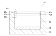
- FIG. 1 is a schematic cross-sectional view showing an example of the multilayer structure according to the present disclosure.
- FIG. 2 is a schematic cross-sectional view showing a modified example of the multilayer structure according to the present disclosure.
- a numerical range represented by “to” means a range including the numerical values before and after “to” as a lower limit value and an upper limit value.
- the upper limit value or the lower limit value described in a certain numerical range may be replaced with the upper limit value or the lower limit value of another stepwise described numerical range.
- the upper limit value or the lower limit value described in a certain numerical range may be replaced with the values shown in the examples.
- the amount of each component in the composition means the total amount of the plurality of substances present in the composition, unless there is a plurality of substances corresponding to each component in the composition, unless otherwise specified. ..
- “mass %” and “weight %” have the same meaning
- “mass part” and “weight part” have the same meaning.
- a combination of two or more preferable aspects is a more preferable aspect.
- a multilayer structure according to the present disclosure includes a radiator, a base layer including a region that forms an interface in an internal structure (hereinafter, may be simply referred to as “base layer”), the radiator, and the base.
- a first air layer provided between the base material layer and the material layer, and the far infrared transmittance B of the base material layer and the solar reflectance A of the multilayer structure are B/(100-A)> 7 is satisfied, and the sunlight reflectance C of the base material layer is 30% or more.
- a multilayer structure according to the present disclosure has an excellent radiative cooling effect, and can cool an object to be cooled arranged inside the structure. Although the reason why the multilayer structure according to the present disclosure exerts the above effect is not clear, it is presumed as follows.
- a multilayer structure according to the present disclosure includes a radiator, a base layer including a region forming an interface in an internal structure, and a first air layer provided between the radiator and the base layer.
- the temperature rise inside the multilayer structure can be reduced by reducing the amount of sunlight entering the multilayer structure due to the reflection of sunlight, and the radiation from the radiator is performed.
- Infrared rays can be easily emitted from the inside of the multilayer structure to the outside of the multilayer structure. Therefore, it is considered that the multilayer structure according to the present disclosure has an excellent radiative cooling effect and can cool the cooled object arranged inside the structure.
- the “inside the structure” in the “object to be cooled arranged inside the structure” means the whole or a part of the region between the radiator and the base material layer.
- cooling the cooled body means lowering the temperature of the cooled body than the temperature outside the multilayer structure, and not necessarily lowering the temperature of the cooled body to a specific temperature.
- the present invention is not limited to this, and includes maintaining the temperature of the cooled object not to exceed the outside air temperature.
- Far-infrared transmittance B of the base material layer and sunlight reflectance A of the multilayer structure more preferably satisfy B/(100-A)>7, and more preferably B/(100-A)>10. /(100-A)>15 is more preferable, B/(100-A)>20 is particularly preferable, and B/(100-A)>25 is most preferable.
- the upper limit value of B/(100-A) is not limited and can be set as appropriate according to the intended use.
- B/(100-A) the value of B (far infrared ray transmittance B of the base material layer) and the value of A (sunlight reflectance A of the multilayer structure) are each expressed as a percentage (%). To be done.
- the relational expression represented by B/(100-A)>7 is such that the sunlight reflectance A of the multilayer structure is large (in other words, the sunlight absorptivity is small) and the far-infrared ray transmission of the base material layer is It means that the rate B is large.
- the condition under which the radiator is cooled by radiation cooling is represented by P in ⁇ P out ⁇ 0 (hereinafter, referred to as “formula (A)”).
- P in represents the solar energy per unit area incident from the outside of the multilayer structure into the inside of the multilayer structure, and is represented by (100 ⁇ A) ⁇ P solar /100.
- A represents the sunlight reflectance (%) of the multilayer structure
- P solar represents the sunlight intensity.
- P out represents the energy radiated from the multilayer structure as far infrared rays per unit area, and is represented by (1- ⁇ sky ) ⁇ B ⁇ T amb 4 /100.
- ⁇ sky represents the effective emissivity of the sky
- B represents the far-infrared transmittance (%) of the base material layer
- ⁇ represents the Stefan-Boltzmann constant
- T amb represents the outside air temperature. .. It is known that ⁇ sky is about 0.7 in fine weather.
- B/(100 ⁇ A)>7 is derived from the equation (A). Therefore, the multilayer structure satisfying B/(100-A)>7 reflects sunlight and has a high far-infrared transmittance, so that it has an excellent radiative cooling effect, and a cooled object placed inside the structure. Can be cooled.
- the solar reflectance A of the multilayer structure can be measured by the following method.
- a method based on the method described in JIS A 5759:2008 using an integrating sphere spectrophotometer (for example, V-670, manufactured by JASCO Corporation), the radiator and the base material layer at wavelengths of 300 nm to 2500 nm Each diffuse reflectance is measured.
- the multilayer structure includes two or more base material layers, the diffuse reflectance is measured for each base material layer.
- the value calculated from the measured value based on the Fresnel multiple reflection theory is defined as the sunlight reflectance A.
- the diffuse reflectance of the other base material layer is also included in the calculation of the solar reflectance A.
- the far infrared ray transmittance B of the base material layer can be measured by the following method. Using a Fourier transform infrared spectrophotometer (eg VIR-100, JASCO Corporation) and an integrating sphere unit, the spectral infrared diffuse reflectance and the spectral infrared diffuse transmittance of the base material layer at a wavelength of 2 ⁇ m to 25 ⁇ m can be measured. taking measurement. When the multilayer structure includes two or more substrate layers, the spectral infrared diffuse transmittance is measured for each substrate layer, and the spectral infrared diffuse transmittance of the substrate layer is calculated based on the Fresnel multiple reflection theory. To calculate.
- a Fourier transform infrared spectrophotometer eg VIR-100, JASCO Corporation
- the value obtained by weighting the black spectral radiation intensity at 25° C. with respect to the obtained spectral infrared diffuse transmittance is defined as the far infrared transmittance B of the base material layer.
- the value obtained by multiplying the infrared diffuse transmittance T by the spectral black body radiation intensity I at a wavelength of 2 ⁇ m to 25 ⁇ m is calculated as “the spectral black body radiation intensity I
- the far-infrared transmittance B of the base material layer can be calculated by dividing by the “value integrated at 2 ⁇ m to 25 ⁇ m”.
- the spectral infrared diffuse transmittance of the other base material layer is also included in the calculation of the far infrared transmittance B.
- T represents the spectral infrared diffuse transmittance (%)
- I represents the spectral black body radiation intensity (W/m 2 ) at 25° C.
- ⁇ represents the wavelength ( ⁇ m).
- FIG. 1 schematically shows an example of a multilayer structure according to the present disclosure.
- the multilayer structure 100 is a radiant cooling structure, and includes a radiator 10, a base material layer 20a, a base material layer 20b, a base material layer 20c, and a first air layer. 30, a second air layer 40a, a second air layer 40b, and a housing 50 having an opening 60.
- the base material layer 20a, the base material layer 20b, and the base material layer 20c are provided in the opening 60 of the housing 50, respectively.
- the first air layer 30 is provided between the radiator 10 and the base material layer 20a.
- the second air layer 40a is provided between the base material layer 20a and the base material layer 20b.
- the second air layer 40b is provided between the base material layer 20b and the base material layer 20c.
- Infrared rays emitted from the radiator 10 pass through the first air layer 30, the base material layer 20a, the second air layer 40a, the base material layer 20b, the second air layer 40b, and the base material layer 20c, It is discharged to the outside of the multilayer structure 100.
- Each of the base material layer 20a, the base material layer 20b, and the base material layer 20c can reduce the temperature rise of the radiator 10 and the like by reducing the amount of sunlight entering the inside of the multilayer structure 100. ..
- the cooled object can be cooled by disposing the cooled object in the region of the first air layer 30 (for example, the surface of the radiator 10). ..
- the multilayer structure according to the present disclosure has a radiator. Since the multilayer structure has a radiator, infrared rays can be emitted and radiative cooling can be exhibited.
- radiator means an object that exhibits a high emissivity in a wavelength range where black body radiation occurs at room temperature (for example, 25° C.).
- the average emissivity of the radiator in the wavelength range of 25° C. and the wavelength of 5 ⁇ m to 25 ⁇ m is preferably 0.8 or more
- the average emissivity of the radiator in the wavelength range of 25° C. and the wavelength of 8 ⁇ m to 13 ⁇ m is It is more preferably 0.8 or more.
- the average emissivity of the radiator in the wavelength range of 5 ⁇ m to 25 ⁇ m can be measured by the following method.
- a Fourier transform infrared spectrophotometer eg, FTS-7000, manufactured by Varian
- FTS-7000 Fourier transform infrared spectrophotometer
- the arithmetic average value of the spectral emissivity at each wavelength is calculated, and the obtained value is set as the average emissivity in the wavelength range of 5 ⁇ m to 25 ⁇ m.
- the average emissivity of the radiator in the wavelength range of 8 ⁇ m to 13 ⁇ m is calculated by selecting the wavelength range of 8 ⁇ m to 13 ⁇ m in the above method instead of the wavelength range of 5 ⁇ m to 25 ⁇ m.
- the radiator is not limited as long as it has a high emissivity.
- Examples of the form of the radiator include a film, a sheet, a coating film, a heat insulating material, and a white reflector.
- the radiator may be a liquid such as water.
- the radiator may be arranged on a support (for example, a glass substrate, a resin film, a resin sheet).
- radiator examples include polyethylene terephthalate, glass, acrylic, urethane, silicone, water and the like.
- the radiator preferably exhibits diffuse reflection or specular reflection with respect to the spectrum of sunlight.
- a foamed resin is preferable, and a foamed polyethylene terephthalate is more preferable.
- radiators may be used as the radiator.
- Specific examples of commercially available products include MCPET (registered trademark, foamed polyethylene terephthalate white reflector, manufactured by Furukawa Electric Co., Ltd.), Lumirror (registered trademark) E20 (polyethylene terephthalate white reflective film, manufactured by Toray Industries, Inc.). Etc.
- the shape of the radiator is not limited and can be appropriately selected according to the application.
- Examples of the shape of the radiator include a planar shape, a curved shape, a spherical shape, a prism shape, and a box shape.
- the shape of the radiator surface is not limited.
- the surface of the radiator may be smooth or may have an uneven structure.
- the size of the radiator is not limited and can be set as appropriate according to the application.
- the thickness of the radiator can be 0.00001 cm to 50 cm.
- the radiator preferably exhibits a high reflectance with respect to sunlight from the viewpoint of reflecting sunlight that has passed through the base material layer.
- the solar reflectance of the radiator is preferably 70% or more, more preferably 80% or more, and particularly preferably 90% or more.
- the solar reflectance of the radiator can be measured by the following method.
- the diffuse reflectance of the radiator at a wavelength of 300 nm to 2500 nm was measured using an integrating sphere spectrophotometer (for example, V-670, manufactured by JASCO Corporation) by a method based on the method described in JIS A 5759:2008.
- the value obtained by measurement is taken as the sunlight reflectance.
- the multilayer structure according to the present disclosure has a base material layer including a region that forms an interface in the internal structure. Further, in the multilayer structure according to the present disclosure, the sunlight reflectance C of the base material layer is 30% or more. By having the base material layer including the region forming the interface in the internal structure and having the sunlight reflectance C of 30% or more, it is possible to enhance the reflectance of sunlight and enhance the radiation cooling effect.
- a region that forms an interface in the internal structure means a region that forms an interface with a main material (that is, a base material (matrix)) that constitutes the base material layer inside the base material layer, and is a tangible material. And intangible.
- the region forming the interface in the internal structure means a “void” that forms a solid-gas interface with the fibers of the nonwoven fabric.
- the region forming the interface in the internal structure means “particles” forming a solid-solid interface with the resin.
- the region forming the interface in the internal structure can be confirmed by observing the cross section of the base material layer using a scanning electron microscope (SEM).
- SEM scanning electron microscope
- the interface formed in the internal structure may be a solid-gas interface, a solid-liquid interface, a solid-solid interface, or a solid in view of sunlight reflectance. It is preferably at least one kind of interface selected from the group consisting of a gas interface and a solid-solid interface, and more preferably a solid-gas interface.
- the region forming the interface in the internal structure includes, for example, voids, bubbles, particles (for example, organic resin particles, inorganic particles) and the like.
- voids for example, a solid-gas interface is formed in the internal structure of the base material layer.
- a solid-solid interface is formed in the internal structure of the base material layer.
- the region forming the interface in the internal structure is preferably at least one selected from voids and particles, and more preferably voids, from the viewpoint of sunlight reflectance.
- the organic resin particles are not limited, and known organic resin particles can be applied. From the viewpoint of the reflectance of sunlight, the organic resin particles are preferably organic resin particles having a refractive index different from that of the material of the base material layer. Specific examples of the organic resin particles include acrylic resin particles, polyester particles, polyurethane particles, polycarbonate particles, polyolefin particles, polystyrene particles and the like.
- the inorganic particles are not limited, and known inorganic particles can be applied. From the viewpoint of sunlight reflectance, the inorganic particles are preferably inorganic particles having a refractive index different from that of the material of the base material layer. Specific examples of the inorganic particles include silicon oxide (silica) particles, titanium oxide (titania) particles, zirconium oxide (zirconia) particles, magnesium oxide (magnesia) particles, aluminum oxide (alumina) particles and the like.
- the shape of the area that forms the interface in the internal structure is not limited.
- the shape of the region forming the interface in the internal structure, which is observed in the cross section of the base material layer, may be, for example, a circular shape, an elliptical shape, or an irregular shape.
- the average diameter of the region forming the interface in the internal structure is preferably 5000 nm or less, more preferably 2000 nm or less, and more preferably 1000 nm or less from the viewpoint of sunlight reflectance and infrared transmittance. More preferably, it is particularly preferably 550 nm or less.
- the average diameter of the region forming the interface in the internal structure is preferably 30 nm or more, more preferably 50 nm or more, and particularly preferably 100 nm or more, from the viewpoint of sunlight reflectance.
- the average diameter of the region forming the interface in the internal structure can be measured by the following method. Ten cross-sections in the thickness direction of the base material layer are observed with a scanning electron microscope (for example, S4100, manufactured by Hitachi High-Technology Co., Ltd.) at a magnification of 1000 times, and a total of 10 observation images are acquired. From each image, 10 areas each forming an interface in the internal structure are selected (however, the number of areas forming an interface in the internal structure (hereinafter, sometimes referred to as “specific area” in this paragraph) is 10). For images that are less than, select a number of specific regions that corresponds to the maximum number of specific regions observed.
- a scanning electron microscope for example, S4100, manufactured by Hitachi High-Technology Co., Ltd.
- the material for the base layer is preferably a resin having a high infrared transmittance.
- the resin having a high infrared ray transmissivity include a resin having an infrared ray transmissivity of 50% or more in any wavelength range of 8 ⁇ m to 13 ⁇ m.
- Specific examples of the resin having a high infrared ray transmittance include chain polyolefins (for example, polyethylene and polypropylene), cyclic polyolefins (for example, polynorbornene), and polystyrene.
- the base material layer preferably contains polyolefin, and more preferably polyethylene, from the viewpoint of infrared ray transmittance.
- the content of the polyolefin in the base material layer is preferably 80% by mass to 100% by mass, and 90% by mass to 100% by mass with respect to the mass of the base material layer from the viewpoint of the infrared transmittance. It is more preferable that the content is 95% by mass to 100% by mass.
- the base material layer is preferably a base material layer containing particles or a porous base material layer, and more preferably a porous base material layer, from the viewpoint of sunlight reflection and infrared transmittance.
- the porous base material layer include a porous resin film and a nonwoven fabric.
- the base material layer is preferably a porous resin film or a non-woven fabric, more preferably a porous polyethylene film or a polyethylene non-woven fabric, and more preferably a polyethylene non-woven fabric, from the viewpoint of sunlight reflection and infrared transmittance. Particularly preferred.
- a commercially available product may be used as the base material layer.
- Examples of commercially available products include Tyvek (registered trademark, manufactured by Asahi DuPont Flash Span Products Co., Ltd.), Sunmap (registered trademark, manufactured by Nitto Denko Corporation), Mirim (registered trademark, Teijin Limited), and the like.
- the sunlight reflectance C of the base material layer is 30% or more, preferably 40% or more, more preferably 50% or more, further preferably 80% or more, and 90% or more. It is particularly preferable that By adjusting the sunlight reflectance C of the base material layer within the above numerical range, the radiation cooling effect is excellent, and the cooled object arranged inside the structure can be cooled.
- the upper limit of the sunlight reflectance C of the base material layer is not limited.
- the sunlight reflectance C of the base material layer can be 100% or less, for example.
- the sunlight reflectance C of the base material layer can be measured by the following method. According to the method described in JIS A 5759:2008, the diffuse reflectance of the base material layer at a wavelength of 300 nm to 2500 nm is measured using an integrating sphere spectrophotometer (for example, V-670, manufactured by JASCO Corporation). Then, the obtained value is defined as the sunlight reflectance C.
- the multilayer structure includes two or more base layers, the diffuse reflectance is measured for each base layer, and the solar reflectance C of the base layer is calculated based on the Fresnel multiple reflection theory. To do. Further, when the multilayer structure includes another base material layer described later, the diffuse reflectance of the other base material layer is also included in the calculation of the solar reflectance C.
- the far infrared ray transmittance B of the base material layer and the solar light reflectance C of the base material layer preferably satisfy B/(100-C)>7, and more preferably B/(100-C)>8. It is particularly preferable to satisfy B/(100-C)>10.
- the far-infrared transmittance B of the base material layer and the sunlight reflectance C of the base material layer satisfy the above relationship, the radiant cooling effect is excellent, and the cooled object arranged inside the structure can be cooled. ..
- the method of measuring the far infrared ray transmittance B of the base material layer and the sunlight reflectance C of the base material layer is as described above.
- the upper limit of B/(100-C) is not limited and can be set appropriately according to the intended use.
- B/(100-C) the value of B (far infrared ray transmittance B of the base material layer) and the value of C (sunlight reflectance C of the base material layer) are each expressed as a percentage (%). To be done.
- the relational expression represented by B/(100-C)>7 is a base material layer in place of the solar reflectance A of the multilayer structure in the relational expression represented by B/(100-A)>7.
- the solar light reflectance C of is considered. That is, the relational expression represented by B/(100-C)>7 means that the sunlight reflectance C of the base material layer is large and the far infrared ray transmittance B of the base material layer is large.
- the porosity of the base material layer is preferably 40% or more, more preferably 45% or more, further preferably 50% or more, and more preferably 60% or more, from the viewpoint of infrared ray transmittance. Is particularly preferable. From the viewpoint of the strength of the base material, the porosity of the base material layer is preferably 90% or less, and more preferably 80% or less.
- the porosity of the base material layer can be measured by the following method.
- the volume and mass of the base material layer are measured to calculate the density of the base material layer.
- the ratio of the density of the base material layer to the density of the material forming the base material layer is calculated, and the obtained value is defined as the porosity of the base material layer.
- the arithmetic mean value of the ratio of the density of the base layer to the density of the material forming the base layer is calculated, and the obtained value is the porosity of the base layer.
- the volume of the base material layer is measured by the Archimedes method (solvent: water, temperature: 25°C), and the mass of the base material layer is measured using a balance.
- the method of measuring the density of the material forming the base material layer the method of measuring the density of the base material layer can be applied, if necessary.
- the number of base material layers is at least one, preferably two or more, and more preferably three or more. By setting the number of base material layers to two or more, the reflectance of sunlight can be improved and a high heat insulating effect can also be obtained.
- the number of base material layers is preferably 7 or less, and more preferably 5 or less, from the viewpoint of infrared transmittance. When there are two or more base material layers, the base material layers may be the same or different from each other.
- the distance between the base material layers is preferably 5 cm or less, more preferably 4 cm or less, and particularly preferably 3 cm or less.
- the lower limit of the distance between the base material layers is not limited.
- the distance between the base material layers can be, for example, 0.1 cm or more.
- the distance between the base material layers can be measured by the following method. The minimum value and the maximum value of the distance between the two base material layers facing each other are measured, and the arithmetic mean value of the measured values is taken as the distance between the base material layers. When the distance between the base material layers is two or more, the distance between the base material layers is obtained by the same method as described above, and the arithmetic mean value of the obtained values is used as the distance between the base material layers.
- the base layer is preferably arranged on the radiator from the viewpoint of radiation cooling.
- the base material layer may be arranged at a position where the horizontal surface and the main surface of the base material layer are parallel to each other, or may be arranged at a position where the horizontal surface and the main surface of the base material layer intersect. From the viewpoint of radiation cooling and sunlight reflectance, the base material layer is preferably arranged at a position where the incident direction of sunlight and the main surface of the base material layer intersect.
- the relative positional relationship of each base material layer is not limited.
- each base material layer may be arranged hierarchically or may not be arranged hierarchically (for example, each base material layer is on the same plane).
- the base material layers are arranged hierarchically from the viewpoint of radiative cooling and solar reflectance, and the incident direction of sunlight and each base material. It is more preferable that the layers are arranged hierarchically at a position where the main surfaces of the layers intersect.
- the “main surface of the base material layer” means the surface of the base material layer orthogonal to the thickness direction of the base material layer.
- the thickness of the base material layer is not limited and can be set appropriately according to the application.
- the thickness of the base material layer may be, for example, 20 ⁇ m to 5000 ⁇ m.
- the base material layer may be provided on an inner peripheral portion, an opening portion, or the like of the housing described later, or may be provided via a spacer.
- the multilayer structure according to the present disclosure has a first air layer provided between the radiator and the base material layer. Since the multilayer structure has the first air layer, a high heat insulating effect can be obtained.
- the medium forming the first air layer is not necessarily limited to air, but may be a gas such as nitrogen or argon. From the viewpoint of workability, the medium forming the first air layer is preferably air.
- the first air layer may be provided between the radiator and the base layer, and the radiator and the base layer facing each other (in the case where the multilayer structure has two or more base layers, It is preferable that the space is formed by a base material layer provided on the side closest to the radiator of the two or more base material layers). Further, the first air layer may be a space formed by the radiator and the other base material layer facing each other without departing from the gist of the present disclosure, and two other base materials facing each other. It may be a space formed by layers. The other base material layers will be described later.
- the size and capacity of the first air layer are not limited and can be appropriately set according to the application.
- the multilayer structure according to the present disclosure has two or more base material layers
- the number of the second air layers may be one, or two or more.
- the second air layer has only to be provided between the base material layers, and from the viewpoint of heat insulation, it is preferably a space formed by two base material layers facing each other.
- the multilayer structure according to the present disclosure preferably has a structure in which the base material layers and the second air layers are alternately arranged from the viewpoint of heat insulation.
- the thickness of the second air layer is preferably 5 cm or less, more preferably 4 cm or less, and particularly preferably 3 cm or less. By adjusting the thickness of the second air layer within the above numerical range, convection in the air layer can be suppressed and the heat insulating effect can be further improved.
- the lower limit of the thickness of the second air layer is not limited.
- the thickness of the second air layer can be, for example, 0.1 cm or more.
- the thickness of the second air layer can be measured by the following method.
- the minimum value and the maximum value of the thickness of the second air layer are measured, and the arithmetic mean value of the measured values is set as the thickness of the second air layer.
- the thickness of the second air layer is obtained by the same method as described above, and the arithmetic mean value of the obtained values is set as the thickness of the second air layer. ..
- the multilayer structure according to the present disclosure includes a region that forms an interface in the internal structure in a range that satisfies B/(100-A)>7 and a range that the solar reflectance C of the base material layer is 30% or more. It may have a base material layer (hereinafter, may be referred to as “other base material layer”). Examples of the other base material layer include resin films such as polyolefin films. The number of other base material layers may be one, or two or more.
- the ratio of the number of base material layers including a region forming an interface in the internal structure is defined as a base material layer including a region forming an interface in the internal structure and a base material layer not including a region forming an interface in the internal structure (that is, It is preferably 50% or more, more preferably 65% or more, further preferably 80% or more, particularly preferably 90% or more, based on the total number of other base material layers). , 100% is most preferable.
- the multilayer structure according to the present disclosure may have a housing.
- a housing for example, a radiator, a base material layer, a first air layer, and the like can be provided inside the housing.
- the case may be composed of a single member, or may be composed of a combination of a plurality of members.
- the housing is preferably made of a heat insulating material from the viewpoint of heat insulating properties.
- the heat insulating material is not limited and can be appropriately selected from known heat insulating materials.
- the housing has an opening at least in the upper part.
- the number of openings is not limited and may be one or may be two or more, and is preferably one from the viewpoint of radiative cooling.
- the shape of the opening is not limited and can be appropriately selected according to the application. Examples of the shape of the opening include a circle, a quadrangle, a hexagon, and an irregular shape.
- FIG. 2 schematically shows a modified example of the multilayer structure according to the present disclosure.
- the multilayer structure 101 is a radiation cooling structure, and has a radiator 11 having an opening 61, a base material layer 21a, a base material layer 21b, and a base material layer 21c. It has a first air layer 31, a second air layer 41a, and a second air layer 41b.
- the base material layer 21a, the base material layer 21b, and the base material layer 21c are provided in the opening 61 of the radiator 11, respectively.
- the first air layer 31 is provided between the radiator 11 and the base material layer 21a.
- the second air layer 41a is provided between the base material layer 21a and the base material layer 21b.
- the second air layer 41b is provided between the base material layer 21b and the base material layer 21c.
- the multilayer structure according to the present disclosure has an excellent radiative cooling effect and can cool an object to be cooled arranged inside the structure, and thus is preferably used as a radiative cooling structure (for example, a radiative cooling device).
- a radiative cooling structure for example, a radiative cooling device.
- the multilayer structure according to the present disclosure can be applied to, for example, a window material, a roof heat shield, a cooler, or the like. Note that the use of the multilayer structure according to the present disclosure is not limited to cooling the cooled object arranged inside the structure.
- the multilayer structure according to the present disclosure can be applied to various cooling techniques utilizing radiative cooling, as exemplified above.
- Example 1 Using a heat insulating material (product name: Styloace-II, manufactured by Dow Kako Co., Ltd.) having a thickness of 10 cm, a housing having one opening at the top was manufactured. The dimensions inside the housing are 30 cm in length, 40 cm in width, and 10 cm in height. As a radiator, a white reflector (foamed polyethylene terephthalate, product name: MCPET, manufactured by Furukawa Electric Co., Ltd.) was provided on the bottom surface inside the housing.
- a white reflector fuoamed polyethylene terephthalate, product name: MCPET, manufactured by Furukawa Electric Co., Ltd.
- one polyethylene non-woven fabric product name: Tyvek 1442R, void ratio: 69%, average diameter of voids: 500 nm, thickness: S: 140 ⁇ m, Asahi DuPont Flash Span Products Co., Ltd. were provided to obtain a multilayer structure (hereinafter, may be simply referred to as “structure”).
- structure An air layer formed of a white reflector and a polyethylene non-woven fabric exists inside the housing.
- Example 2 A multilayer structure was obtained in the same manner as in Example 1 except that two polyethylene nonwoven fabrics used in Example 1 were provided at intervals of 4 cm. In addition, the distance between the polyethylene nonwoven fabric closest to the white reflector and the white reflector is 2 cm.
- Example 3 A multilayer structure was obtained in the same manner as in Example 1 except that three polyethylene nonwoven fabrics used in Example 1 were provided at 3 cm intervals. In addition, the distance between the polyethylene nonwoven fabric closest to the white reflector and the white reflector is 2 cm.
- Example 4 Instead of the polyethylene nonwoven fabric used in Example 1, a porous polyethylene film (product name: Sunmap LC0.2t, porosity: 30%, average diameter of pores: 4000 nm, thickness: 200 ⁇ m, manufactured by Nitto Denko Corporation) is used. A multilayer structure was obtained in the same manner as in Example 1 except for the above.
- a porous polyethylene film product name: Sunmap LC0.2t, porosity: 30%, average diameter of pores: 4000 nm, thickness: 200 ⁇ m, manufactured by Nitto Denko Corporation
- Example 5 A multilayer structure was obtained in the same manner as in Example 4 except that two porous polyethylene films used in Example 4 were provided at 4 cm intervals. The distance between the porous polyethylene film closest to the white reflector and the white reflector is 2 cm.
- Example 6 A multilayer structure was obtained in the same manner as in Example 4 except that three porous polyethylene films used in Example 4 were provided at 3 cm intervals. The distance between the porous polyethylene film closest to the white reflector and the white reflector is 2 cm.
- ⁇ Comparative example 2> A multilayer structure was obtained in the same manner as in Example 1 except that a polyethylene film (product name: SAN8041, thickness: 50 ⁇ m, manufactured by Sunplatec Co., Ltd.) was used instead of the polyethylene nonwoven fabric used in Example 1.
- the polyethylene film used in Comparative Example 2 is a base material layer that does not include a region that forms an interface in the internal structure.
- Example 3 A multilayer structure was obtained in the same manner as in Example 1 except that polyethylene terephthalate film (product name: Lumirror S10, thickness: 188 ⁇ m, manufactured by Toray Industries, Inc.) was used instead of the polyethylene nonwoven fabric used in Example 1. It was
- ⁇ Comparative example 4> Instead of the polyethylene nonwoven fabric used in Example 1, a porous polyethylene film (product name: Sunmap LC0.1t, porosity: 30%, average diameter of voids: 4000 nm, thickness: 100 ⁇ m, manufactured by Nitto Denko Corporation) is used. A multilayer structure was obtained in the same manner as in Example 1 except for the above.
- a porous polyethylene film product name: Sunmap LC0.1t, porosity: 30%, average diameter of voids: 4000 nm, thickness: 100 ⁇ m, manufactured by Nitto Denko Corporation
- test piece temperature T1 (° C.) and the outside air temperature T2 (° C.) are average temperatures in the above time period.
- Standard A: 5° C. ⁇ T2-T1 B: 0°C ⁇ T2-T1 ⁇ 5°C C: T2-T1 ⁇ 0° C. (that is, T1>T2)
- W (T2-C) ⁇ J ⁇ D/(T1-T2)
- C represents the outside air temperature (unit: °C)
- J represents the surface thermal conductivity (W/(m 2 ⁇ K))
- D represents the thickness of the structure (unit: m (meter) )).
- the thickness of the structure means the distance from the lower surface of the radiator to the base material layer which is the most surface layer of the base material layers.
- the radiator, the base material layer including a region forming an interface in the internal structure, and the first air layer provided between the radiator and the base material layer are provided.
- Example 1 in which the far infrared ray transmittance B of the layer and the sunlight reflectance A of the multilayer structure satisfy B/(100-A)>7, and the sunlight reflectance C of the base material layer is 30% or more. It was found that the multilayer structures of ⁇ 6 have excellent radiative cooling effect and low thermal conductivity in the daytime. Since the far-infrared ray transmittance B of the base material layer and the sunlight reflectance C of the base material layer satisfy B/(100-C)>7, the multilayer structures of Examples 2 to 3 are particularly excellent in radiation cooling. It was found to have an effect. It was also found that the radiation cooling effect is improved and the thermal conductivity is further reduced by setting the number of base material layers included in the multilayer structure to two or more.
- Comparative Examples 1 to 4 were inferior to the structures of Examples 1 to 6 in the radiation cooling effect and had high thermal conductivity.
Landscapes
- Physics & Mathematics (AREA)
- General Physics & Mathematics (AREA)
- Optics & Photonics (AREA)
- Health & Medical Sciences (AREA)
- Toxicology (AREA)
- Engineering & Computer Science (AREA)
- Mechanical Engineering (AREA)
- Thermal Sciences (AREA)
- General Engineering & Computer Science (AREA)
- Laminated Bodies (AREA)
Abstract
放射体と、内部構造において界面を形成する領域を含む基材層と、上記放射体及と上記基材層との間に設けられた第1の空気層と、を有し、上記基材層の遠赤外線透過率B及び多層構造体の太陽光反射率Aが、B/(100-A)>7を満たし、上記基材層の太陽光反射率Cが、30%以上である多層構造体を提供する。
Description
本開示は、多層構造体に関する。
近年、省エネルギーの観点から、冷房器具、建築物等において放射冷却を利用する冷却技術が検討されている。
例えば、米国特許出願公開第2015/0338175号明細書には、物体を冷却するための放射冷却装置であって、上記物体に対して深さ寸法に沿って異なる深さに位置する複数の異なる材料の配置を含み、上記複数の異なる材料は、太陽スペクトル反射部分及び熱放射性部分を含む放射冷却装置が開示されている。
特開昭57-150767号公報には、放熱板の上方に、相互に所定の空間を保って対面している数枚の長波長透過率の高い透明板を、放熱板と対面させた状態でかつ所定の間隔を保って設けたことを特徴とする放射冷却器が開示されている。
また、建築物においては、断熱性を有する構造体も検討されている。例えば、特開2008-114583号公報には、3枚以上の透光性を有する基材フィルムが、スペーサ用樹脂組成物からなる複数の樹脂スペーサを挟んで各々対向した構造を有する多層構造体であって、上記樹脂スペーサは、上記基材フィルムを挟んで、上記基材フィルムの積層方向に重ねて配置されていることを特徴とする多層構造体が開示されている。
放射冷却を利用する冷却技術の応用の1つとして、放射冷却機能を有する構造体の内部に配置された被冷却体を冷却する技術が挙げられる。しかしながら、従来提案されている技術では、構造体の内部への太陽光の入射等によって十分な放射冷却効果を発現することができず、この結果、構造体の内部に配置された被冷却体を十分に冷却できないといった問題が生じる場合がある。例えば、米国特許出願公開第2015/0338175号明細書に記載された放射冷却装置では、高い断熱効果を得ることができず、また、窓材としてポリエチレンフィルムを用いているため、放射冷却装置の内部まで太陽光が到達することによって放射冷却効果が小さくなると考えられる。特開昭57-150767号公報に記載された放射冷却器においても、放射冷却器の内部まで太陽光が到達することによって十分な放射冷却効果を得ることができないと考えられる。また、特開2008-114583号公報に記載された多層構造体においては、多層構造体の可視光線透過率を高める必要があるため、基材フィルムの赤外線透過率は小さいと考えられる。さらに、特開2008-114583号公報に記載された多層構造体においては、透光性を有する基材フィルムが用いられているため、多層構造体の内部にまで太陽光が到達することによって放射冷却効果が小さくなると考えられる。
本開示は、上記の事情に鑑みてなされたものである。
本開示の一態様は、放射冷却効果に優れ、構造体の内部に配置された被冷却体を冷却することができる多層構造体を提供することを目的とする。
本開示の一態様は、放射冷却効果に優れ、構造体の内部に配置された被冷却体を冷却することができる多層構造体を提供することを目的とする。
上記課題を解決するための手段には、以下の態様が含まれる。
<1> 放射体と、内部構造において界面を形成する領域を含む基材層と、上記放射体及と上記基材層との間に設けられた第1の空気層と、を有し、上記基材層の遠赤外線透過率B及び多層構造体の太陽光反射率Aが、B/(100-A)>7を満たし、上記基材層の太陽光反射率Cが、30%以上である多層構造体。
<2> 上記基材層の遠赤外線透過率B及び上記基材層の太陽光反射率Cが、B/(100-C)>7を満たす<1>に記載の多層構造体。
<3> 上記基材層の数が、2つ以上である<1>又は<2>に記載の多層構造体。
<4> 上記基材層間に第2の空気層を有する<3>に記載の多層構造体。
<5> 上記基材層と上記第2の空気層とが交互に配置された構造を有する請求項<4>に記載の多層構造体。
<6> 上記第2の空気層の厚さが、5cm以下である<4>又は<5>に記載の多層構造体。
<7> 上記基材層の遠赤外線透過率B及び多層構造体の太陽光反射率Aが、B/(100-A)>20を満たす<1>~<6>のいずれか1つに記載の多層構造体。
<8> 上記基材層の太陽光反射率Cが、80%以上である<1>~<7>のいずれか1つに記載の多層構造体。
<9> 上記内部構造において界面を形成する領域の平均直径が、5000nm以下である<1>~<8>のいずれか1つに記載の多層構造体。
<10> 上記内部構造において界面を形成する領域が、空隙及び粒子から選択される少なくとも1種である<1>~<9>のいずれか1つに記載の多層構造体。
<11> 上記基材層が、多孔質基材層である<1>~<10>のいずれか1つに記載の多層構造体。
<12> 上記基材層の空隙率が、40%以上である<1>~<11>のいずれか1つに記載の多層構造体。
<13> 上記基材層が、ポリオレフィンを含む<1>~<12>のいずれか1つに記載の多層構造体。
<14> 放射冷却構造体である、<1>~<13>のいずれか1つに記載の多層構造体。
<1> 放射体と、内部構造において界面を形成する領域を含む基材層と、上記放射体及と上記基材層との間に設けられた第1の空気層と、を有し、上記基材層の遠赤外線透過率B及び多層構造体の太陽光反射率Aが、B/(100-A)>7を満たし、上記基材層の太陽光反射率Cが、30%以上である多層構造体。
<2> 上記基材層の遠赤外線透過率B及び上記基材層の太陽光反射率Cが、B/(100-C)>7を満たす<1>に記載の多層構造体。
<3> 上記基材層の数が、2つ以上である<1>又は<2>に記載の多層構造体。
<4> 上記基材層間に第2の空気層を有する<3>に記載の多層構造体。
<5> 上記基材層と上記第2の空気層とが交互に配置された構造を有する請求項<4>に記載の多層構造体。
<6> 上記第2の空気層の厚さが、5cm以下である<4>又は<5>に記載の多層構造体。
<7> 上記基材層の遠赤外線透過率B及び多層構造体の太陽光反射率Aが、B/(100-A)>20を満たす<1>~<6>のいずれか1つに記載の多層構造体。
<8> 上記基材層の太陽光反射率Cが、80%以上である<1>~<7>のいずれか1つに記載の多層構造体。
<9> 上記内部構造において界面を形成する領域の平均直径が、5000nm以下である<1>~<8>のいずれか1つに記載の多層構造体。
<10> 上記内部構造において界面を形成する領域が、空隙及び粒子から選択される少なくとも1種である<1>~<9>のいずれか1つに記載の多層構造体。
<11> 上記基材層が、多孔質基材層である<1>~<10>のいずれか1つに記載の多層構造体。
<12> 上記基材層の空隙率が、40%以上である<1>~<11>のいずれか1つに記載の多層構造体。
<13> 上記基材層が、ポリオレフィンを含む<1>~<12>のいずれか1つに記載の多層構造体。
<14> 放射冷却構造体である、<1>~<13>のいずれか1つに記載の多層構造体。
本開示の一態様によれば、放射冷却効果に優れ、構造体の内部に配置された被冷却体を冷却することができる多層構造体を提供することができる。
以下、本開示の実施形態について詳細に説明する。なお、本開示は、以下の実施形態に何ら制限されず、本開示の目的の範囲内において、適宜変更を加えて実施することができる。
本開示において、「~」を用いて表される数値範囲は、「~」の前後に記載される数値を下限値及び上限値として含む範囲を意味する。本開示に段階的に記載されている数値範囲において、ある数値範囲で記載された上限値又は下限値は、他の段階的な記載の数値範囲の上限値又は下限値に置き換えてもよい。また、本開示に記載されている数値範囲において、ある数値範囲で記載された上限値又は下限値は、実施例に示されている値に置き換えてもよい。
本開示において、組成物中の各成分の量は、組成物中に各成分に該当する物質が複数存在する場合、特に断らない限り、組成物中に存在する複数の物質の合計量を意味する。
本開示において、「質量%」と「重量%」とは同義であり、「質量部」と「重量部」とは同義である。
本開示において、2以上の好ましい態様の組み合わせは、より好ましい態様である。
本開示において、組成物中の各成分の量は、組成物中に各成分に該当する物質が複数存在する場合、特に断らない限り、組成物中に存在する複数の物質の合計量を意味する。
本開示において、「質量%」と「重量%」とは同義であり、「質量部」と「重量部」とは同義である。
本開示において、2以上の好ましい態様の組み合わせは、より好ましい態様である。
<多層構造体>
本開示に係る多層構造体は、放射体と、内部構造において界面を形成する領域を含む基材層(以下、単に「基材層」ということがある。)と、上記放射体及と上記基材層との間に設けられた第1の空気層と、を有し、上記基材層の遠赤外線透過率B及び多層構造体の太陽光反射率Aが、B/(100-A)>7を満たし、上記基材層の太陽光反射率Cが、30%以上である。
本開示に係る多層構造体は、放射体と、内部構造において界面を形成する領域を含む基材層(以下、単に「基材層」ということがある。)と、上記放射体及と上記基材層との間に設けられた第1の空気層と、を有し、上記基材層の遠赤外線透過率B及び多層構造体の太陽光反射率Aが、B/(100-A)>7を満たし、上記基材層の太陽光反射率Cが、30%以上である。
本開示に係る多層構造体は、放射冷却効果に優れ、構造体の内部に配置された被冷却体を冷却することができる。本開示に係る多層構造体が上記効果を奏する理由は明らかではないものの、以下のように推察される。
本開示に係る多層構造体は、放射体と、内部構造において界面を形成する領域を含む基材層と、上記放射体及と上記基材層との間に設けられた第1の空気層と、を有し、上記基材層の遠赤外線透過率B及び多層構造体の太陽光反射率Aが、B/(100-A)>7を満たし、上記基材層の太陽光反射率Cが、30%以上であるため、太陽光の反射によって多層構造体内部に入射する太陽光の量を低減することで多層構造体内部の温度上昇を低減することができ、そして、放射体から放射される赤外線を多層構造体の内部から多層構造体の外部に向かって容易に放出することができる。このため、本開示に係る多層構造体は、放射冷却効果に優れ、構造体の内部に配置された被冷却体を冷却することができると考えられる。
本開示に係る多層構造体は、放射体と、内部構造において界面を形成する領域を含む基材層と、上記放射体及と上記基材層との間に設けられた第1の空気層と、を有し、上記基材層の遠赤外線透過率B及び多層構造体の太陽光反射率Aが、B/(100-A)>7を満たし、上記基材層の太陽光反射率Cが、30%以上であるため、太陽光の反射によって多層構造体内部に入射する太陽光の量を低減することで多層構造体内部の温度上昇を低減することができ、そして、放射体から放射される赤外線を多層構造体の内部から多層構造体の外部に向かって容易に放出することができる。このため、本開示に係る多層構造体は、放射冷却効果に優れ、構造体の内部に配置された被冷却体を冷却することができると考えられる。
本開示において、「構造体の内部に配置された被冷却体」における「構造体の内部」とは、放射体と基材層との間の領域の全体又は一部を意味する。
本開示において、「被冷却体を冷却する」とは、被冷却体の温度を多層構造体の外部の温度よりも低くすることを意味し、必ずしも被冷却体の温度を特定の温度まで下げることに限られるものではなく、被冷却体の温度が外気温度を上回らない状態を維持することを包含する。
基材層の遠赤外線透過率B及び多層構造体の太陽光反射率Aは、B/(100-A)>7を満たし、B/(100-A)>10を満たすことがより好ましく、B/(100-A)>15を満たすことがさらに好ましく、B/(100-A)>20を満たすことが特に好ましく、B/(100-A)>25を満たすことが最も好ましい。基材層の遠赤外線透過率B及び多層構造体の太陽光反射率Aが上記関係を満たすことで、放射冷却効果に優れ、構造体の内部に配置された被冷却体を冷却することができる。なお、B/(100-A)の上限値は、制限されず、用途等に応じて適宜設定することができる。本開示においては、例えば、100>B/(100-A)であってもよく、70>B/(100-A)であってもよく、50>B/(100-A)であってもよい。「B/(100-A)」において、B(基材層の遠赤外線透過率B)の値及びA(多層構造体の太陽光反射率A)の値は、それぞれ、百分率(%)で表される。
B/(100-A)>7で表される関係式は、多層構造体の太陽光反射率Aが大きく(換言すると、太陽光の吸収率が小さく)、かつ、基材層の遠赤外線透過率Bが大きいことを意味する。本開示に係る多層構造体において、放射冷却により放射体が冷却される条件は、Pin-Pout<0(以下、「式(A)」という。)で表される。式(A)中、Pinは、多層構造体の外部から多層構造体の内部へ入射する単位面積当たりの太陽光エネルギーを表し、(100-A)×Psolar/100で表される。ここで、Aは、多層構造体の太陽光反射率(%)を表し、Psolarは、太陽光強度を表す。式(A)中、Poutは、多層構造体から遠赤外線として単位面積当たりに放射されるエネルギーを表し、(1-εsky)×B×σ×Tamb
4/100で表される。ここで、εskyは、空の実効放射率を表し、Bは、基材層の遠赤外線透過率(%)を表し、σは、シュテファン-ボルツマン定数を表し、Tambは、外気温度を表す。εskyは、晴天時には0.7程度であることが知られている。典型的な気象条件として、Psolarを1000W/m2、εskyを0.7、Tambを300Kと仮定した場合、式(A)より、B/(100-A)>7が導かれる。よって、B/(100-A)>7を満たす多層構造体は、太陽光を反射し、遠赤外線の透過率が高いため、放射冷却効果に優れ、構造体の内部に配置された被冷却体を冷却することができる。
多層構造体の太陽光反射率Aは、以下の方法によって測定することができる。
JIS A 5759:2008に記載された方法に準拠する方法によって、積分球分光光度計(例えば、V-670、日本分光株式会社製)を用いて、波長300nm~2500nmにおける放射体及び基材層の拡散反射率をそれぞれ測定する。多層構造体に2つ以上の基材層が含まれる場合には、基材層毎に拡散反射率を測定する。測定値より、フレネル多重反射理論に基づいて算出される値を太陽光反射率Aとする。なお、多層構造体に後述する他の基材層が含まれる場合には、他の基材層の拡散反射率も太陽光反射率Aの算出に含める。
JIS A 5759:2008に記載された方法に準拠する方法によって、積分球分光光度計(例えば、V-670、日本分光株式会社製)を用いて、波長300nm~2500nmにおける放射体及び基材層の拡散反射率をそれぞれ測定する。多層構造体に2つ以上の基材層が含まれる場合には、基材層毎に拡散反射率を測定する。測定値より、フレネル多重反射理論に基づいて算出される値を太陽光反射率Aとする。なお、多層構造体に後述する他の基材層が含まれる場合には、他の基材層の拡散反射率も太陽光反射率Aの算出に含める。
基材層の遠赤外線透過率Bは、以下の方法によって測定することができる。
フーリエ変換赤外分光光度計(例えば、VIR-100、日本分光株式会社)及び積分球ユニットを用いて、波長2μm~25μmにおける基材層の分光赤外拡散反射率及び分光赤外拡散透過率を測定する。多層構造体に2つ以上の基材層が含まれる場合には、基材層毎に分光赤外拡散透過率を測定し、フレネル多重反射理論に基づいて基材層の分光赤外拡散透過率を算出する。次に、得られる分光赤外拡散透過率に対して、25℃における黒体輻射強度の重みづけを行うことによって得られる値を、基材層の遠赤外線透過率Bとする。具体的には、下記式にしたがって、「赤外拡散透過率Tに分光黒体輻射強度Iを乗じて得られる値を波長2μm~25μmにおいて積分した値」を「分光黒体輻射強度Iを波長2μm~25μmにおいて積分した値」で除することによって、基材層の遠赤外線透過率Bを算出することができる。なお、多層構造体に後述する他の基材層が含まれる場合には、他の基材層の分光赤外拡散透過率も遠赤外線透過率Bの算出に含める。
フーリエ変換赤外分光光度計(例えば、VIR-100、日本分光株式会社)及び積分球ユニットを用いて、波長2μm~25μmにおける基材層の分光赤外拡散反射率及び分光赤外拡散透過率を測定する。多層構造体に2つ以上の基材層が含まれる場合には、基材層毎に分光赤外拡散透過率を測定し、フレネル多重反射理論に基づいて基材層の分光赤外拡散透過率を算出する。次に、得られる分光赤外拡散透過率に対して、25℃における黒体輻射強度の重みづけを行うことによって得られる値を、基材層の遠赤外線透過率Bとする。具体的には、下記式にしたがって、「赤外拡散透過率Tに分光黒体輻射強度Iを乗じて得られる値を波長2μm~25μmにおいて積分した値」を「分光黒体輻射強度Iを波長2μm~25μmにおいて積分した値」で除することによって、基材層の遠赤外線透過率Bを算出することができる。なお、多層構造体に後述する他の基材層が含まれる場合には、他の基材層の分光赤外拡散透過率も遠赤外線透過率Bの算出に含める。

上記式中、Tは、分光赤外拡散透過率(%)を表し、Iは、25℃における分光黒体輻射強度(W/m2)を表し、λは、波長(μm)を表す。
本開示に係る多層構造体の一例について図面を参照しながら説明する。図1は、本開示に係る多層構造体の一例を概略的に示している。例えば図1に示されるように、多層構造体100は、放射冷却構造体であり、放射体10と、基材層20aと、基材層20bと、基材層20cと、第1の空気層30と、第2の空気層40aと、第2の空気層40bと、開口部60を有する筐体50と、を有する。基材層20a、基材層20b、及び基材層20cは、筐体50の開口部60にそれぞれ設けられている。第1の空気層30は、放射体10と基材層20aとの間に設けられている。第2の空気層40aは、基材層20aと基材層20bとの間に設けられている。第2の空気層40bは、基材層20bと基材層20cとの間に設けられている。放射体10から放射される赤外線は、第1の空気層30、基材層20a、第2の空気層40a、基材層20b、第2の空気層40b、及び基材層20cを通過し、多層構造体100の外部に放出される。基材層20a、基材層20b、及び基材層20cはそれぞれ、多層構造体100の内部に入射する太陽光の量を低減することで、放射体10等の温度上昇を低減することができる。また、基材層間に設けられた第2の空気層40a及び第2の空気層40bにおいては、対流が抑制されているため、多層構造体100の断熱性が向上する。また、図1に示される多層構造体100においては、第1の空気層30の領域(例えば、放射体10の表面)に被冷却体を配置することで、被冷却体を冷却することができる。
以下、本開示に係る多層構造体について具体的に説明する。
[放射体]
本開示に係る多層構造体は、放射体を有する。多層構造体が放射体を有することで、赤外線を放射し、放射冷却を発現することができる。
本開示に係る多層構造体は、放射体を有する。多層構造体が放射体を有することで、赤外線を放射し、放射冷却を発現することができる。
本開示において、「放射体」とは、室温(例えば25℃)で黒体輻射が生じる波長域において、高い放射率を示す物体を意味する。具体的に、25℃、波長5μm~25μmの波長域における放射体の平均放射率が0.8以上であることが好ましく、25℃、波長8μm~13μmの波長域における放射体の平均放射率が0.8以上であることがより好ましい。
波長5μm~25μmの波長域における放射体の平均放射率は、以下の方法によって測定することができる。
フーリエ変換赤外分光光度計(例えば、FTS-7000、Varian社製)を用いて、25℃、波長5μm~25μmの波長域における測定試料の分光透過率及び分光反射率をそれぞれ測定する。波長5μm~25μmの波長域において、波長0.5μm毎にキルヒホッフの法則(分光放射率=1-分光透過率-分光反射率)より分光放射率を算出する。各波長における分光放射率の算術平均値を求め、得られる値を5μm~25μmの波長範囲における平均放射率とする。
なお、波長8μm~13μmの波長域における放射体の平均放射率は、上記方法において、波長5μm~25μmの波長域に代えて波長8μm~13μmの波長域を選択することによって算出される。
フーリエ変換赤外分光光度計(例えば、FTS-7000、Varian社製)を用いて、25℃、波長5μm~25μmの波長域における測定試料の分光透過率及び分光反射率をそれぞれ測定する。波長5μm~25μmの波長域において、波長0.5μm毎にキルヒホッフの法則(分光放射率=1-分光透過率-分光反射率)より分光放射率を算出する。各波長における分光放射率の算術平均値を求め、得られる値を5μm~25μmの波長範囲における平均放射率とする。
なお、波長8μm~13μmの波長域における放射体の平均放射率は、上記方法において、波長5μm~25μmの波長域に代えて波長8μm~13μmの波長域を選択することによって算出される。
放射体は、高い放射率を示す物体であれば制限されない。放射体の形態として、例えば、フィルム、シート、塗装膜、断熱材、白色反射板等が挙げられる。また、放射体は、水等の液体であってもよい。また、放射体は、支持体(例えば、ガラス基板、樹脂フィルム、樹脂シート)上に配置されていてもよい。
放射体を構成する材料としては、例えば、ポリエチレンテレフタレート、ガラス、アクリル、ウレタン、シリコーン、水等が挙げられる。
放射体は、赤外線放射率及び太陽光反射率の観点から、太陽光のスペクトルに対して拡散反射又は鏡面反射を示すことが好ましい。特に生産性の観点から発泡樹脂であることが好ましく、発泡ポリエチレンテレフタレートであることがより好ましい。
放射体としては、市販品を用いてもよい。市販品の具体例としては、MCPET(登録商標、発泡ポリエチレンテレフタレート製の白色反射板、古河電気工業株式会社製)、ルミラー(登録商標)E20(ポリエチレンテレフタレート製の白色反射フイルム、東レ株式会社製)等が挙げられる。
放射体の形状は、制限されず、用途等に応じて適宜選択することができる。放射体の形状としては、例えば、平面形状、湾曲形状、球形、角柱形状、箱型形状等が挙げられる。
放射体の表面の形状は、制限されない。放射体の表面は、平滑であってもよく、凹凸構造を有していてもよい。
放射体の大きさは、制限されず、用途等に応じて適宜設定することができる。例えば、放射体の厚さは、0.00001cm~50cmとすることができる。
放射体は、基材層を透過した太陽光を反射するという観点から、太陽光に対して高い反射率を示すことが好ましい。放射体の太陽光反射率は、70%以上であることが好ましく、80%以上であることがより好ましく、90%以上であることが特に好ましい。
放射体の太陽光反射率は、以下の方法によって測定することができる。
JIS A 5759:2008に記載された方法に準拠する方法によって、積分球分光光度計(例えば、V-670、日本分光株式会社製)を用いて、波長300nm~2500nmにおける放射体の拡散反射率を測定し、得られる値を太陽光反射率とする。
JIS A 5759:2008に記載された方法に準拠する方法によって、積分球分光光度計(例えば、V-670、日本分光株式会社製)を用いて、波長300nm~2500nmにおける放射体の拡散反射率を測定し、得られる値を太陽光反射率とする。
[基材層]
本開示に係る多層構造体は、内部構造において界面を形成する領域を含む基材層を有する。また、本開示に係る多層構造体において、上記基材層の太陽光反射率Cは、30%以上である。内部構造において界面を形成する領域を含み、太陽光反射率Cが30%以上である基材層を有することで、太陽光の反射率を高め、放射冷却効果を高めることができる。
本開示に係る多層構造体は、内部構造において界面を形成する領域を含む基材層を有する。また、本開示に係る多層構造体において、上記基材層の太陽光反射率Cは、30%以上である。内部構造において界面を形成する領域を含み、太陽光反射率Cが30%以上である基材層を有することで、太陽光の反射率を高め、放射冷却効果を高めることができる。
本開示において、「内部構造において界面を形成する領域」とは、基材層内部において基材層を構成する主要材料(すなわち、母材(マトリックス))と界面を形成する領域を意味し、有体物及び無体物を包含する。例えば、基材層が不織布である場合、内部構造において界面を形成する領域とは、不織布の繊維と固体-気体界面を形成する「空隙」を意味する。また、例えば、基材層が粒子を含む樹脂フィルムである場合、内部構造において界面を形成する領域とは、樹脂と固体-固体界面を形成する「粒子」を意味する。内部構造において界面を形成する領域は、走査型電子顕微鏡(SEM)を用いて、基材層の断面を観察することで確認することができる。内部構造において界面を形成する領域の数は、1つ、又は2つ以上であってもよい。
内部構造において形成される界面としては、固体-気体界面であってもよく、固体-液体界面であってもよく、固体-固体界面であってもよく、太陽光の反射率の観点から、固体-気体界面及び固体-固体界面からなる群より選択される少なくとも1種の界面であることが好ましく、固体-気体界面であることがより好ましい。
内部構造において界面を形成する領域としては、例えば、空隙、気泡、粒子(例えば、有機樹脂粒子、無機粒子)等が挙げられる。例えば、内部構造において界面を形成する領域が空隙である場合、基材層の内部構造においては固体-気体界面が形成される。また、例えば、内部構造において界面を形成する領域が粒子である場合、基材層の内部構造においては固体-固体界面が形成される。内部構造において界面を形成する領域は、太陽光の反射率の観点から、空隙及び粒子から選択される少なくとも1種であることが好ましく、空隙であることがより好ましい。
有機樹脂粒子としては、制限されず、公知の有機樹脂粒子を適用することができる。有機樹脂粒子は、太陽光の反射率の観点から、基材層の材料とは異なる屈折率を有する有機樹脂粒子であることが好ましい。有機樹脂粒子の具体例としては、アクリル樹脂粒子、ポリエステル粒子、ポリウレタン粒子、ポリカーボネート粒子、ポリオレフィン粒子、ポリスチレン粒子等が挙げられる。
無機粒子としては、制限されず、公知の無機粒子を適用することができる。無機粒子は、太陽光の反射率の観点から、基材層の材料とは異なる屈折率を有する無機粒子であることが好ましい。無機粒子の具体例としては、酸化ケイ素(シリカ)粒子、酸化チタン(チタニア)粒子、酸化ジルコニウム(ジルコニア)粒子、酸化マグネシウム(マグネシア)粒子、酸化アルミニウム(アルミナ)粒子等が挙げられる。
内部構造において界面を形成する領域の形状は、制限されない。基材層の断面で観察される、内部構造において界面を形成する領域の形状は、例えば、円形状であってもよく、楕円形状であってもよく、不定形状であってもよい。
内部構造において界面を形成する領域の平均直径は、太陽光の反射率及び赤外線の透過率の観点から、5000nm以下であることが好ましく、2000nm以下であることがより好ましく、1000nm以下であることがさらに好ましく、550nm以下であることが特に好ましい。
内部構造において界面を形成する領域の平均直径は、太陽光の反射率の観点から、30nm以上であることが好ましく、50nm以上であることがより好ましく、100nm以上であることが特に好ましい。
内部構造において界面を形成する領域の平均直径は、以下の方法によって測定することができる。
基材層の厚さ方向の断面10箇所を、走査型電子顕微鏡(例えば、S4100、株式会社日立ハイテクノロジー製)を用いて倍率1000倍で観察し、合計10枚の観察像を取得する。各画像から、内部構造において界面を形成する領域を10個ずつ選択する(ただし、内部構造において界面を形成する領域(以下、本段落において「特定領域」ということがある。)の数が10個未満である画像については、観察される特定領域の最大数に対応する数の特定領域を選択する。)。選択された内部構造において界面を形成する領域の外周をトレースし、画像解析装置を用いてトレース像から内部構造において界面を形成する領域の円相当径の算術平均値を求め、得られる値を、内部構造において界面を形成する領域の平均直径とする。
基材層の厚さ方向の断面10箇所を、走査型電子顕微鏡(例えば、S4100、株式会社日立ハイテクノロジー製)を用いて倍率1000倍で観察し、合計10枚の観察像を取得する。各画像から、内部構造において界面を形成する領域を10個ずつ選択する(ただし、内部構造において界面を形成する領域(以下、本段落において「特定領域」ということがある。)の数が10個未満である画像については、観察される特定領域の最大数に対応する数の特定領域を選択する。)。選択された内部構造において界面を形成する領域の外周をトレースし、画像解析装置を用いてトレース像から内部構造において界面を形成する領域の円相当径の算術平均値を求め、得られる値を、内部構造において界面を形成する領域の平均直径とする。
基材層の材料は、赤外線の透過率が高い樹脂であることが好ましい。赤外線の透過率が高い樹脂としては、例えば、8μm~13μmの範囲のいずれかの波長の赤外線の透過率が50%以上である樹脂等が挙げられる。赤外線の透過率が高い樹脂の具体例としては、鎖状ポリオレフィン(例えば、ポリエチレン、ポリプロピレン)、環状ポリオレフィン(例えば、ポリノルボルネン)、ポリスチレン等が挙げられる。
上記の中でも、基材層は、赤外線の透過率の観点から、ポリオレフィンを含むことが好ましく、ポリエチレンを含むことが好ましい。
基材層中のポリオレフィンの含有量は、赤外線の透過率の観点から、基材層の質量に対して、80質量%~100質量%であることが好ましく、90質量%~100質量%であることがより好ましく、95質量%~100質量%であることが特に好ましい。
基材層は、太陽光の反射及び赤外線の透過率の観点から、粒子を含む基材層、又は多孔質基材層であることが好ましく、多孔質基材層であることが好ましい。多孔質基材層としては、例えば、多孔質樹脂フィルム、不織布等が挙げられる。基材層は、太陽光の反射及び赤外線の透過率の観点から、多孔質樹脂フィルム又は不織布であることが好ましく、多孔質ポリエチレンフィルム又はポリエチレン不織布であることがより好ましく、ポリエチレン不織布であることが特に好ましい。
基材層としては、市販品を用いてもよい。市販品としては、例えば、タイベック(登録商標、旭・デュポン フラッシュスパン プロダクツ株式会社製)、サンマップ(登録商標、日東電工株式会社製)、ミライム(登録商標、帝人株式会社)等が挙げられる。
基材層の太陽光反射率Cは、30%以上であり、40%以上であることが好ましく、50%以上であることがより好ましく、80%以上であることがさらに好ましく、90%以上であることが特に好ましい。基材層の太陽光反射率Cを上記数値範囲に調節することで、放射冷却効果に優れ、構造体の内部に配置された被冷却体を冷却することができる。基材層の太陽光反射率Cの上限値は、制限されない。基材層の太陽光反射率Cは、例えば100%以下とすることができる。
基材層の太陽光反射率Cは、以下の方法によって測定することができる。
JIS A 5759:2008に記載された方法に準拠し、積分球分光光度計(例えば、V-670、日本分光株式会社製)を用いて、波長300nm~2500nmにおける基材層の拡散反射率を測定し、得られる値を太陽光反射率Cとする。なお、多層構造体に2つ以上の基材層が含まれる場合には、基材層毎に拡散反射率を測定し、フレネル多重反射理論に基づいて基材層の太陽光反射率Cを算出する。また、多層構造体に後述する他の基材層が含まれる場合には、他の基材層の拡散反射率も太陽光反射率Cの算出に含める。
JIS A 5759:2008に記載された方法に準拠し、積分球分光光度計(例えば、V-670、日本分光株式会社製)を用いて、波長300nm~2500nmにおける基材層の拡散反射率を測定し、得られる値を太陽光反射率Cとする。なお、多層構造体に2つ以上の基材層が含まれる場合には、基材層毎に拡散反射率を測定し、フレネル多重反射理論に基づいて基材層の太陽光反射率Cを算出する。また、多層構造体に後述する他の基材層が含まれる場合には、他の基材層の拡散反射率も太陽光反射率Cの算出に含める。
基材層の遠赤外線透過率B及び基材層の太陽光反射率Cは、B/(100-C)>7を満たすことが好ましく、B/(100-C)>8を満たすことがより好ましく、B/(100-C)>10を満たすことが特に好ましい。基材層の遠赤外線透過率B及び基材層の太陽光反射率Cが上記関係を満たすことで、放射冷却効果に優れ、構造体の内部に配置された被冷却体を冷却することができる。基材層の遠赤外線透過率B及び基材層の太陽光反射率Cの測定方法は、上記において説明したとおりである。なお、B/(100-C)の上限値は、制限されず、用途等に応じて適宜設定することができる。本開示においては、例えば、100>B/(100-C)であってもよく、50>B/(100-C)であってもよく、30>B/(100-C)であってもよい。「B/(100-C)」において、B(基材層の遠赤外線透過率B)の値及びC(基材層の太陽光反射率C)の値は、それぞれ、百分率(%)で表される。
B/(100-C)>7で表される関係式は、上記B/(100-A)>7で表される関係式において、多層構造体の太陽光反射率Aに代えて基材層の太陽光反射率Cを考慮したものである。すなわち、B/(100-C)>7で表される関係式は、基材層の太陽光反射率Cが大きく、かつ、基材層の遠赤外線透過率Bが大きいことを意味する。
基材層の空隙率は、赤外線の透過率の観点から、40%以上であることが好ましく、45%以上であることがより好ましく、50%以上であることがさらに好ましく、60%以上であることが特に好ましい。基材層の空隙率は、基材強度の観点から、90%以下であることが好ましく、80%以下であることがより好ましい。
基材層の空隙率は、以下の方法によって測定することができる。
基材層の体積及び質量を測定し、基材層の密度を算出する。基材層を構成する材料の密度に対する基材層の密度の比率を算出し、得られる値を基材層の空隙率とする。空隙を有する基材層が2つ以上である場合には、基材層を構成する材料の密度に対する基材層の密度の比率の算術平均値を求め、得られる値を基材層の空隙率とする。基材層の空隙率の測定において、基材層の体積は、アルキメデス法(溶媒:水、温度:25℃)によって測定し、基材層の質量は、秤を用いて測定する。基材層を構成する材料の密度の測定方法についても、必要に応じて、基材層の密度の測定方法を適用することができる。
基材層の体積及び質量を測定し、基材層の密度を算出する。基材層を構成する材料の密度に対する基材層の密度の比率を算出し、得られる値を基材層の空隙率とする。空隙を有する基材層が2つ以上である場合には、基材層を構成する材料の密度に対する基材層の密度の比率の算術平均値を求め、得られる値を基材層の空隙率とする。基材層の空隙率の測定において、基材層の体積は、アルキメデス法(溶媒:水、温度:25℃)によって測定し、基材層の質量は、秤を用いて測定する。基材層を構成する材料の密度の測定方法についても、必要に応じて、基材層の密度の測定方法を適用することができる。
基材層の数は、少なくとも1つであり、2つ以上であることが好ましく、3つ以上であることがより好ましい。基材層の数を2つ以上とすることで、太陽光の反射率を向上させることができ、高い断熱効果を得ることもできる。基材層の数は、赤外線の透過率の観点から、7つ以下であることが好ましく、5つ以下であることがより好ましい。基材層が2つ以上である場合、基材層は、同一のものであってもよく、互いに異なるものであってもよい。
基材層の数が2つ以上である場合、基材層間の間隔は、5cm以下であることが好ましく、4cm以下であることがより好ましく、3cm以下であることが特に好ましい。基材層間の間隔の下限値は、制限されない。基材層間の間隔は、例えば0.1cm以上とすることができる。
基材層間の間隔は、以下の方法によって測定することができる。
互いに対向する2つの基材層間の間隔の最小値及び最大値を測定し、測定値の算術平均値を基材層間の間隔とする。基材層の間隔が2つ以上である場合には、上記と同様の方法によって基材層の間隔をそれぞれ求め、得られる値の算術平均値を基材層間の間隔とする。
互いに対向する2つの基材層間の間隔の最小値及び最大値を測定し、測定値の算術平均値を基材層間の間隔とする。基材層の間隔が2つ以上である場合には、上記と同様の方法によって基材層の間隔をそれぞれ求め、得られる値の算術平均値を基材層間の間隔とする。
基材層は、放射冷却の観点から、放射体の上に配置されていることが好ましい。基材層は、水平面と基材層の主面とが平行になる位置に配置されていてもよく、水平面と基材層の主面とが交差する位置に配置されていてもよい。基材層は、放射冷却及び太陽光反射率の観点から、太陽光の入射方向と基材層の主面とが交差する位置に配置されていることが好ましい。また、基材層の数が2つ以上である場合、各基材層の相対的な位置関係は、制限されない。基材層の数が2つ以上である場合、各基材層は、階層的に配置されていてもよく、階層的に配置されていなくてもよい(例えば、各基材層は、同一平面上に配置されていてもよい。)。基材層の数が2つ以上である場合、各基材層は、放射冷却及び太陽光反射率の観点から、階層的に配置されていることが好ましく、太陽光の入射方向と各基材層の主面とが交差する位置に階層的に配置されていることがより好ましい。ここで、「基材層の主面」とは、基材層の厚さ方向に直交する基材層の面を意味する。
基材層の厚さは、制限されず、用途等に応じて適宜設定することができる。基材層の厚さは、例えば、20μm~5000μmとすることができる。
基材層は、後述する筐体の内周部、開口部等に設けられてもよく、スペーサーを介して設けられてもよい。
[第1の空気層]
本開示に係る多層構造体は、放射体と基材層との間に設けられた第1の空気層を有する。多層構造体が第1の空気層を有することで、高い断熱効果を得ることができる。
本開示に係る多層構造体は、放射体と基材層との間に設けられた第1の空気層を有する。多層構造体が第1の空気層を有することで、高い断熱効果を得ることができる。
第1の空気層を構成する媒体は、必ずしも空気に限られず、窒素、アルゴン等の気体であってもよい。第1の空気層を構成する媒体は、作業性の観点から、空気であることが好ましい。
第1の空気層は、放射体と基材層との間に設けられていればよく、互いに対向する放射体及び基材層(多層構造体が2つ以上の基材層を有する場合には、2つ以上の基材層のうち最も放射体に近い側に設けられた基材層を指す。)で形成される空間であることが好ましい。また、第1の空気層は、本開示の趣旨を逸脱しない限りにおいて、互いに対向する放射体及び他の基材層で形成される空間であってもよく、互いに対向する2つの他の基材層で形成される空間であってもよい。他の基材層については後述する。
第1の空気層の大きさ及び容量は、制限されず、用途に応じて適宜設定することができる。
[第2の空気層]
本開示に係る多層構造体が2つ以上の基材層を有する場合、本開示に係る多層構造体は、基材層間に第2の空気層を有することが好ましい。基材層間に第2の空気層を設けることで、高い断熱効果を得ることができる。第2の空気層の数は、1つ、又は2つ以上であってもよい。
本開示に係る多層構造体が2つ以上の基材層を有する場合、本開示に係る多層構造体は、基材層間に第2の空気層を有することが好ましい。基材層間に第2の空気層を設けることで、高い断熱効果を得ることができる。第2の空気層の数は、1つ、又は2つ以上であってもよい。
第2の空気層は、基材層間に設けられていればよく、断熱性の観点から、互いに対向する2つの基材層で形成される空間であることが好ましい。本開示に係る多層構造体は、断熱性の観点から、基材層と第2の空気層とが交互に配置された構造を有することが好ましい。
第2の空気層の厚さは、5cm以下であることが好ましく、4cm以下であることがより好ましく、3cm以下であることが特に好ましい。第2の空気層の厚さを上記数値範囲に調節することで、空気層における対流を抑制し、断熱効果をより向上させることができる。第2の空気層の厚さの下限値は、制限されない。第2の空気層の厚さは、例えば0.1cm以上とすることができる。
第2の空気層の厚さは、以下の方法によって測定することができる。
第2の空気層の厚さの最小値及び最大値を測定し、測定値の算術平均値を第2の空気層の厚さとする。第2の空気層が2つ以上である場合には、上記と同様の方法によって第2の空気層の厚さをそれぞれ求め、得られる値の算術平均値を第2の空気層の厚さとする。
第2の空気層の厚さの最小値及び最大値を測定し、測定値の算術平均値を第2の空気層の厚さとする。第2の空気層が2つ以上である場合には、上記と同様の方法によって第2の空気層の厚さをそれぞれ求め、得られる値の算術平均値を第2の空気層の厚さとする。
[他の部材]
(内部構造において界面を形成する領域を含まない基材層)
本開示に係る多層構造体は、B/(100-A)>7を満たす範囲及び基材層の太陽光反射率Cが30%以上となる範囲において、内部構造において界面を形成する領域を含まない基材層(以下、「他の基材層」ということがある。)を有していてもよい。他の基材層としては、例えば、ポリオレフィンフィルム等の樹脂フィルムが挙げられる。他の基材層の数は、1つ、又は2つ以上であってもよい。
(内部構造において界面を形成する領域を含まない基材層)
本開示に係る多層構造体は、B/(100-A)>7を満たす範囲及び基材層の太陽光反射率Cが30%以上となる範囲において、内部構造において界面を形成する領域を含まない基材層(以下、「他の基材層」ということがある。)を有していてもよい。他の基材層としては、例えば、ポリオレフィンフィルム等の樹脂フィルムが挙げられる。他の基材層の数は、1つ、又は2つ以上であってもよい。
内部構造において界面を形成する領域を含む基材層の数の比率は、内部構造において界面を形成する領域を含む基材層及び内部構造において界面を形成する領域を含まない基材層(すなわち、他の基材層)の総数に対して、50%以上であることが好ましく、65%以上であることがより好ましく、80%以上であることがさらに好ましく、90%以上であることが特に好ましく、100%であることが最も好ましい。
(筐体)
本開示に係る多層構造体は、筐体を有していてもよい。本開示に係る多層構造体が筐体を有する場合、例えば、筐体の内部に、放射体、基材層、第1の空気層等を設けることができる。
本開示に係る多層構造体は、筐体を有していてもよい。本開示に係る多層構造体が筐体を有する場合、例えば、筐体の内部に、放射体、基材層、第1の空気層等を設けることができる。
筐体は、単一の部材から構成されるものであってもよく、複数の部材を組み合わせて構成されるものであってもよい。筐体は、断熱性の観点から、断熱材から構成されるものであることが好ましい。断熱材としては、制限されず、公知の断熱材から適宜選択することができる。
筐体は、放射冷却の観点から、少なくとも上部に開口部を有することが好ましい。開口部の数は、制限されず、1つであってもよく、2つ以上であってもよく、放射冷却の観点から、1つであることが好ましい。開口部の形状は、制限されず、用途等に応じて適宜選択することができる。開口部の形状としては、例えば、円形、四角形、六角形、不定形等が挙げられる。
[変形例]
本開示に係る多層構造体の変形例について図面を参照しながら説明する。図2は、本開示に係る多層構造体の変形例を概略的に示している。例えば図2に示されるように、多層構造体101は、放射冷却構造体であり、開口部61を有する放射体11と、基材層21aと、基材層21bと、基材層21cと、第1の空気層31と、第2の空気層41aと、第2の空気層41bと、を有する。基材層21a、基材層21b、及び基材層21cは、放射体11の開口部61にそれぞれ設けられている。第1の空気層31は、放射体11と基材層21aとの間に設けられている。第2の空気層41aは、基材層21aと基材層21bとの間に設けられている。第2の空気層41bは、基材層21bと基材層21cとの間に設けられている。
本開示に係る多層構造体の変形例について図面を参照しながら説明する。図2は、本開示に係る多層構造体の変形例を概略的に示している。例えば図2に示されるように、多層構造体101は、放射冷却構造体であり、開口部61を有する放射体11と、基材層21aと、基材層21bと、基材層21cと、第1の空気層31と、第2の空気層41aと、第2の空気層41bと、を有する。基材層21a、基材層21b、及び基材層21cは、放射体11の開口部61にそれぞれ設けられている。第1の空気層31は、放射体11と基材層21aとの間に設けられている。第2の空気層41aは、基材層21aと基材層21bとの間に設けられている。第2の空気層41bは、基材層21bと基材層21cとの間に設けられている。
[用途]
本開示に係る多層構造体は、放射冷却効果に優れ、構造体の内部に配置された被冷却体を冷却することができるため、放射冷却構造体(例えば、放射冷却装置)として好適に用いることができる。具体的に、本開示に係る多層構造体は、例えば、窓材、屋上の遮熱材、保冷装置等に適用することができる。なお、本開示に係る多層構造体の用途は、構造体の内部に配置された被冷却体の冷却に限られるものではない。本開示に係る多層構造体は、上記で例示したとおり、放射冷却を利用する種々の冷却技術に適用することができる。
本開示に係る多層構造体は、放射冷却効果に優れ、構造体の内部に配置された被冷却体を冷却することができるため、放射冷却構造体(例えば、放射冷却装置)として好適に用いることができる。具体的に、本開示に係る多層構造体は、例えば、窓材、屋上の遮熱材、保冷装置等に適用することができる。なお、本開示に係る多層構造体の用途は、構造体の内部に配置された被冷却体の冷却に限られるものではない。本開示に係る多層構造体は、上記で例示したとおり、放射冷却を利用する種々の冷却技術に適用することができる。
以下、実施例により本開示を詳細に説明するが、本開示はこれらに制限されるものではない。
<実施例1>
厚さ10cmの断熱材(品名:スタイロエース-II、ダウ化工株式会社製)を用い、上部に開口部を1つ有する筐体を作製した。筐体内部の寸法は、縦30cm、横40cm、高さ10cmである。放射体として、筐体内部の底面に白色反射板(発泡ポリエチレンテレフタレート、品名:MCPET、古河電気工業株式会社製)を設けた。次に、白色反射板の表面から開口部の方向に向かって10cmの位置に、基材層として1枚のポリエチレン不織布(品名:タイベック1442R、空隙率:69%、空隙の平均直径:500nm、厚さ:140μm、旭・デュポン フラッシュスパン プロダクツ株式会社製)を設けることによって、多層構造体(以下、単に「構造体」ということがある。)を得た。筐体内部には、白色反射板とポリエチレン不織布とで形成される空気層が存在する。
厚さ10cmの断熱材(品名:スタイロエース-II、ダウ化工株式会社製)を用い、上部に開口部を1つ有する筐体を作製した。筐体内部の寸法は、縦30cm、横40cm、高さ10cmである。放射体として、筐体内部の底面に白色反射板(発泡ポリエチレンテレフタレート、品名:MCPET、古河電気工業株式会社製)を設けた。次に、白色反射板の表面から開口部の方向に向かって10cmの位置に、基材層として1枚のポリエチレン不織布(品名:タイベック1442R、空隙率:69%、空隙の平均直径:500nm、厚さ:140μm、旭・デュポン フラッシュスパン プロダクツ株式会社製)を設けることによって、多層構造体(以下、単に「構造体」ということがある。)を得た。筐体内部には、白色反射板とポリエチレン不織布とで形成される空気層が存在する。
<実施例2>
実施例1で用いたポリエチレン不織布を4cm間隔で2枚設けた点以外は、実施例1と同様にして多層構造体を得た。なお、白色反射板に最も近い側のポリエチレン不織布と白色反射板との距離は、2cmである。
実施例1で用いたポリエチレン不織布を4cm間隔で2枚設けた点以外は、実施例1と同様にして多層構造体を得た。なお、白色反射板に最も近い側のポリエチレン不織布と白色反射板との距離は、2cmである。
<実施例3>
実施例1で用いたポリエチレン不織布を3cm間隔で3枚設けた点以外は、実施例1と同様にして多層構造体を得た。なお、白色反射板に最も近い側のポリエチレン不織布と白色反射板との距離は、2cmである。
実施例1で用いたポリエチレン不織布を3cm間隔で3枚設けた点以外は、実施例1と同様にして多層構造体を得た。なお、白色反射板に最も近い側のポリエチレン不織布と白色反射板との距離は、2cmである。
<実施例4>
実施例1で用いたポリエチレン不織布の代わりに多孔質ポリエチレンフィルム(品名:サンマップLC0.2t、空隙率:30%、空隙の平均直径:4000nm、厚さ:200μm、日東電工株式会社製)を用いた点以外は、実施例1と同様にして多層構造体を得た。
実施例1で用いたポリエチレン不織布の代わりに多孔質ポリエチレンフィルム(品名:サンマップLC0.2t、空隙率:30%、空隙の平均直径:4000nm、厚さ:200μm、日東電工株式会社製)を用いた点以外は、実施例1と同様にして多層構造体を得た。
<実施例5>
実施例4で用いた多孔質ポリエチレンフィルムを、4cm間隔で2枚設けた点以外は、実施例4と同様にして多層構造体を得た。なお、白色反射板に最も近い側の多孔質ポリエチレンフィルムと白色反射板との距離は、2cmである。
実施例4で用いた多孔質ポリエチレンフィルムを、4cm間隔で2枚設けた点以外は、実施例4と同様にして多層構造体を得た。なお、白色反射板に最も近い側の多孔質ポリエチレンフィルムと白色反射板との距離は、2cmである。
<実施例6>
実施例4で用いた多孔質ポリエチレンフィルムを、3cm間隔で3枚設けた点以外は、実施例4と同様にして多層構造体を得た。なお、白色反射板に最も近い側の多孔質ポリエチレンフィルムと白色反射板との距離は、2cmである。
実施例4で用いた多孔質ポリエチレンフィルムを、3cm間隔で3枚設けた点以外は、実施例4と同様にして多層構造体を得た。なお、白色反射板に最も近い側の多孔質ポリエチレンフィルムと白色反射板との距離は、2cmである。
<比較例1>
ポリエチレン不織布を用いない点以外は、実施例1と同様にして構造体を得た。
ポリエチレン不織布を用いない点以外は、実施例1と同様にして構造体を得た。
<比較例2>
実施例1で用いたポリエチレン不織布の代わりにポリエチレンフィルム(品名:SAN8041、厚さ:50μm、株式会社サンプラテック製)を用いた点以外は、実施例1と同様にして多層構造体を得た。なお、比較例2で用いた上記ポリエチレンフィルムは、内部構造において界面を形成する領域を含まない基材層である。
実施例1で用いたポリエチレン不織布の代わりにポリエチレンフィルム(品名:SAN8041、厚さ:50μm、株式会社サンプラテック製)を用いた点以外は、実施例1と同様にして多層構造体を得た。なお、比較例2で用いた上記ポリエチレンフィルムは、内部構造において界面を形成する領域を含まない基材層である。
<比較例3>
実施例1で用いたポリエチレン不織布の代わりにポリエチレンテレフタラートフイルム(品名:ルミラーS10、厚さ:188μm、東レ株式会社製)を用いた点以外は、実施例1と同様にして多層構造体を得た。
実施例1で用いたポリエチレン不織布の代わりにポリエチレンテレフタラートフイルム(品名:ルミラーS10、厚さ:188μm、東レ株式会社製)を用いた点以外は、実施例1と同様にして多層構造体を得た。
<比較例4>
実施例1で用いたポリエチレン不織布の代わりに多孔質ポリエチレンフィルム(品名:サンマップLC0.1t、空隙率:30%、空隙の平均直径:4000nm、厚さ:100μm、日東電工株式会社製)を用いた点以外は、実施例1と同様にして多層構造体を得た。
実施例1で用いたポリエチレン不織布の代わりに多孔質ポリエチレンフィルム(品名:サンマップLC0.1t、空隙率:30%、空隙の平均直径:4000nm、厚さ:100μm、日東電工株式会社製)を用いた点以外は、実施例1と同様にして多層構造体を得た。
<評価>
[放射冷却効果]
実施例1~6及び比較例1~4の各構造体中の白色反射板表面の中央に、試験片として2cm角の黒色プラスチック片を配置した。次に、試験片が配置された各構造体を、屋外にて、晴天時の日が昇っている時間帯(AM11時~PM1時)に設置した。各構造体の設置の際、筐体の開口部を天頂方向に向けて配置した。熱電対を用いて、試験片の温度T1(℃)、及び外気温度T2(℃)を測定し、以下の基準に基づいて放射冷却効果を評価した。評価結果を表1に示す。なお、試験片の温度T1(℃)及び外気温度T2(℃)は、上記時間帯における平均温度である。
(基準)
A:5℃≦T2-T1
B:0℃≦T2-T1<5℃
C:T2-T1<0℃(すなわち、T1>T2)
[放射冷却効果]
実施例1~6及び比較例1~4の各構造体中の白色反射板表面の中央に、試験片として2cm角の黒色プラスチック片を配置した。次に、試験片が配置された各構造体を、屋外にて、晴天時の日が昇っている時間帯(AM11時~PM1時)に設置した。各構造体の設置の際、筐体の開口部を天頂方向に向けて配置した。熱電対を用いて、試験片の温度T1(℃)、及び外気温度T2(℃)を測定し、以下の基準に基づいて放射冷却効果を評価した。評価結果を表1に示す。なお、試験片の温度T1(℃)及び外気温度T2(℃)は、上記時間帯における平均温度である。
(基準)
A:5℃≦T2-T1
B:0℃≦T2-T1<5℃
C:T2-T1<0℃(すなわち、T1>T2)
[熱伝導率]
実施例1~6及び比較例1~4の各構造体において、白色反射板と筐体内部の底面(断熱材)との間に、低温(-5℃以下)の保冷剤を配置し、さらに、開口部をアルミ箔で覆った。熱電対を用いて、白色反射板表面の中央部の温度T1(℃)及び基材層のうち最も表層に配置された基材層の中央部の温度T2(℃)をそれぞれ測定した。実施例1~4及び比較例1~2の各多層構造体の熱伝導率Wを、下記式によって算出した。評価結果を表1に示す。
実施例1~6及び比較例1~4の各構造体において、白色反射板と筐体内部の底面(断熱材)との間に、低温(-5℃以下)の保冷剤を配置し、さらに、開口部をアルミ箔で覆った。熱電対を用いて、白色反射板表面の中央部の温度T1(℃)及び基材層のうち最も表層に配置された基材層の中央部の温度T2(℃)をそれぞれ測定した。実施例1~4及び比較例1~2の各多層構造体の熱伝導率Wを、下記式によって算出した。評価結果を表1に示す。
式:W=(T2-C)×J×D/(T1-T2)
式中、Cは、外気温度(単位:℃)を表し、Jは、表面熱伝導率(W/(m2・K))を表し、Dは、構造体の厚さ(単位:m(メートル))を表す。ここで、構造体の厚さとは、放射体の下面から基材層のうち最も表層に配置された基材層までの距離を意味する。
式中、Cは、外気温度(単位:℃)を表し、Jは、表面熱伝導率(W/(m2・K))を表し、Dは、構造体の厚さ(単位:m(メートル))を表す。ここで、構造体の厚さとは、放射体の下面から基材層のうち最も表層に配置された基材層までの距離を意味する。

表1より、放射体と、内部構造において界面を形成する領域を含む基材層と、放射体及と基材層との間に設けられた第1の空気層と、を有し、基材層の遠赤外線透過率B及び多層構造体の太陽光反射率Aが、B/(100-A)>7を満たし、基材層の太陽光反射率Cが、30%以上である実施例1~6の多層構造体は、日中において、優れた放射冷却効果を有し、熱伝導率も低いことがわかった。実施例2~3の多層構造体は、基材層の遠赤外線透過率B及び基材層の太陽光反射率Cが、B/(100-C)>7を満たすため、特に優れた放射冷却効果を有することがわかった。また、多層構造体に含まれる基材層の数を2つ以上とすることで、放射冷却効果が向上し、熱伝導率もより低くなることがわかった。
一方、比較例1~4の構造体は、実施例1~6の構造体に比べて、放射冷却効果に劣り、熱伝導率も高いことがわかった。
2018年12月4日に出願された日本国特許出願2018-227602号の開示は、その全体が参照により本明細書に取り込まれる。本明細書に記載された全ての文献、特許出願、及び技術規格は、個々の文献、特許出願、及び技術規格が参照により取り込まれることが具体的かつ個々に記載された場合と同程度に、本明細書に参照により取り込まれる。
Claims (14)
- 放射体と、
内部構造において界面を形成する領域を含む基材層と、
前記放射体及と前記基材層との間に設けられた第1の空気層と、
を有し、
前記基材層の遠赤外線透過率B及び多層構造体の太陽光反射率Aが、B/(100-A)>7を満たし、
前記基材層の太陽光反射率Cが、30%以上である多層構造体。 - 前記基材層の遠赤外線透過率B及び前記基材層の太陽光反射率Cが、B/(100-C)>7を満たす請求項1に記載の多層構造体。
- 前記基材層の数が、2つ以上である請求項1又は請求項2に記載の多層構造体。
- 前記基材層間に第2の空気層を有する請求項3に記載の多層構造体。
- 前記基材層と前記第2の空気層とが交互に配置された構造を有する請求項4に記載の多層構造体。
- 前記第2の空気層の厚さが、5cm以下である請求項4又は請求項5に記載の多層構造体。
- 前記基材層の遠赤外線透過率B及び多層構造体の太陽光反射率Aが、B/(100-A)>20を満たす請求項1~請求項6のいずれか1項に記載の多層構造体。
- 前記基材層の太陽光反射率Cが、80%以上である請求項1~請求項7のいずれか1項に記載の多層構造体。
- 前記内部構造において界面を形成する領域の平均直径が、5000nm以下である請求項1~請求項8のいずれか1項に記載の多層構造体。
- 前記内部構造において界面を形成する領域が、空隙及び粒子から選択される少なくとも1種である請求項1~請求項9のいずれか1項に記載の多層構造体。
- 前記基材層が、多孔質基材層である請求項1~請求項10のいずれか1項に記載の多層構造体。
- 前記基材層の空隙率が、40%以上である請求項1~請求項11のいずれか1項に記載の多層構造体。
- 前記基材層が、ポリオレフィンを含む請求項1~請求項12のいずれか1項に記載の多層構造体。
- 放射冷却構造体である、請求項1~請求項13のいずれか1項に記載の多層構造体。
Priority Applications (2)
| Application Number | Priority Date | Filing Date | Title |
|---|---|---|---|
| JP2020559854A JP6942270B2 (ja) | 2018-12-04 | 2019-11-13 | 多層構造体 |
| US17/337,436 US11360249B2 (en) | 2018-12-04 | 2021-06-03 | Multilayer structure |
Applications Claiming Priority (2)
| Application Number | Priority Date | Filing Date | Title |
|---|---|---|---|
| JP2018-227602 | 2018-12-04 | ||
| JP2018227602 | 2018-12-04 |
Related Child Applications (1)
| Application Number | Title | Priority Date | Filing Date |
|---|---|---|---|
| US17/337,436 Continuation US11360249B2 (en) | 2018-12-04 | 2021-06-03 | Multilayer structure |
Publications (1)
| Publication Number | Publication Date |
|---|---|
| WO2020116111A1 true WO2020116111A1 (ja) | 2020-06-11 |
Family
ID=70973980
Family Applications (1)
| Application Number | Title | Priority Date | Filing Date |
|---|---|---|---|
| PCT/JP2019/044510 Ceased WO2020116111A1 (ja) | 2018-12-04 | 2019-11-13 | 多層構造体 |
Country Status (3)
| Country | Link |
|---|---|
| US (1) | US11360249B2 (ja) |
| JP (1) | JP6942270B2 (ja) |
| WO (1) | WO2020116111A1 (ja) |
Families Citing this family (1)
| Publication number | Priority date | Publication date | Assignee | Title |
|---|---|---|---|---|
| US12209826B2 (en) * | 2018-07-02 | 2025-01-28 | Massachusetts Institute Of Technology | Passive radiative cooling during the day |
Citations (6)
| Publication number | Priority date | Publication date | Assignee | Title |
|---|---|---|---|---|
| JPS61223468A (ja) * | 1985-03-26 | 1986-10-04 | 株式会社竹中工務店 | 放射冷却器 |
| JP4743365B2 (ja) * | 2001-03-26 | 2011-08-10 | 独立行政法人産業技術総合研究所 | 壁構造 |
| US20150338175A1 (en) * | 2014-05-21 | 2015-11-26 | The Board Of Trustees Of The Leland Stanford Junior University | Radiative cooling with solar spectrum reflection |
| WO2018062011A1 (ja) * | 2016-09-30 | 2018-04-05 | 富士フイルム株式会社 | 放射冷却装置 |
| WO2018062541A1 (ja) * | 2016-09-30 | 2018-04-05 | 富士フイルム株式会社 | 積層構造 |
| WO2018062012A1 (ja) * | 2016-09-30 | 2018-04-05 | 富士フイルム株式会社 | 放射冷却装置 |
Family Cites Families (4)
| Publication number | Priority date | Publication date | Assignee | Title |
|---|---|---|---|---|
| IT1076556B (it) * | 1977-01-17 | 1985-04-27 | Montedison Spa | Elemento di copertura schermante dalla radiazione solare,particolarmente adatto alle applicazioni della refrigerazione per irraggiamento |
| JPS57150767A (en) | 1981-03-13 | 1982-09-17 | Matsushita Electric Works Ltd | Radiation cooler |
| JP2008114583A (ja) | 2006-10-11 | 2008-05-22 | Sekisui Chem Co Ltd | 多層構造体 |
| WO2017143222A1 (en) * | 2016-02-17 | 2017-08-24 | The Board Of Trustees Of The Leland Stanford Junior University | Infrared-transparent porous polymer textile for human body cooling and heating |
-
2019
- 2019-11-13 WO PCT/JP2019/044510 patent/WO2020116111A1/ja not_active Ceased
- 2019-11-13 JP JP2020559854A patent/JP6942270B2/ja active Active
-
2021
- 2021-06-03 US US17/337,436 patent/US11360249B2/en active Active
Patent Citations (6)
| Publication number | Priority date | Publication date | Assignee | Title |
|---|---|---|---|---|
| JPS61223468A (ja) * | 1985-03-26 | 1986-10-04 | 株式会社竹中工務店 | 放射冷却器 |
| JP4743365B2 (ja) * | 2001-03-26 | 2011-08-10 | 独立行政法人産業技術総合研究所 | 壁構造 |
| US20150338175A1 (en) * | 2014-05-21 | 2015-11-26 | The Board Of Trustees Of The Leland Stanford Junior University | Radiative cooling with solar spectrum reflection |
| WO2018062011A1 (ja) * | 2016-09-30 | 2018-04-05 | 富士フイルム株式会社 | 放射冷却装置 |
| WO2018062541A1 (ja) * | 2016-09-30 | 2018-04-05 | 富士フイルム株式会社 | 積層構造 |
| WO2018062012A1 (ja) * | 2016-09-30 | 2018-04-05 | 富士フイルム株式会社 | 放射冷却装置 |
Also Published As
| Publication number | Publication date |
|---|---|
| JPWO2020116111A1 (ja) | 2021-09-27 |
| US20210286116A1 (en) | 2021-09-16 |
| US11360249B2 (en) | 2022-06-14 |
| JP6942270B2 (ja) | 2021-09-29 |
Similar Documents
| Publication | Publication Date | Title |
|---|---|---|
| Xie et al. | Subambient daytime radiative cooling of vertical surfaces | |
| Yue et al. | Polymer composites with hierarchical architecture and dielectric particles for efficient daytime subambient radiative cooling | |
| US10591190B2 (en) | Radiative cooling device | |
| US20190184687A1 (en) | Laminated structure | |
| Ma et al. | Multilayered SiO2/Si3N4 photonic emitter to achieve high-performance all-day radiative cooling | |
| Zhou et al. | Hybrid concentrated radiative cooling and solar heating in a single system | |
| Suichi et al. | Performance limit of daytime radiative cooling in warm humid environment | |
| Kou et al. | Daytime radiative cooling using near-black infrared emitters | |
| Cui et al. | Progress of passive daytime radiative cooling technologies towards commercial applications | |
| KR102336770B1 (ko) | 메타물질-보강된 수동형 복사 냉각 패널 | |
| Zhang et al. | A flexible film to block solar radiation for daytime radiative cooling | |
| Jeon et al. | Scalable, patternable glass‐infiltrated ceramic radiative coolers for energy‐saving architectural applications | |
| CN110216924A (zh) | 一种复合辐射制冷膜 | |
| JP6602488B2 (ja) | 放射冷却装置 | |
| US11919574B2 (en) | Apparatuses and methods involving thermally tuned composite material | |
| Feng et al. | Optimization of random silica-polymethylpentene (TPX) radiative coolers towards substantial cooling capacity | |
| Alden et al. | Radiative cooling by silicone-based coating with randomly distributed microbubble inclusions | |
| Jayathilaka et al. | Highly efficient polystyrene/metal oxide fiber composites for passive radiative cooling | |
| US11360249B2 (en) | Multilayer structure | |
| Alimohammadian et al. | Innovative strategy of passive sub-ambient radiative cooler through incorporation of a thermal rectifier to double-layer nanoparticle-based coating | |
| Xie et al. | Performance investigations of the easily manufactured composite all-day radiative cooling materials based on PDMS | |
| Nie et al. | High-Thermal-Conductivity Radiative Cooling Films for Enhanced Passive Daytime Cooling | |
| Manzano et al. | Performance and Relative Humidity Impact of Cellulose‐Derivative Networks in All‐Day Passive Radiative Cooling | |
| Wan et al. | Bilayer structured coating for radiative cooling applications | |
| She et al. | Scattering‐Enhanced Light Extraction for Radiative Thermal Load Mitigation in Fluorescent Films |
Legal Events
| Date | Code | Title | Description |
|---|---|---|---|
| 121 | Ep: the epo has been informed by wipo that ep was designated in this application |
Ref document number: 19892971 Country of ref document: EP Kind code of ref document: A1 |
|
| ENP | Entry into the national phase |
Ref document number: 2020559854 Country of ref document: JP Kind code of ref document: A |
|
| NENP | Non-entry into the national phase |
Ref country code: DE |
|
| 122 | Ep: pct application non-entry in european phase |
Ref document number: 19892971 Country of ref document: EP Kind code of ref document: A1 |