WO2020116049A1 - 電気機器 - Google Patents
電気機器 Download PDFInfo
- Publication number
- WO2020116049A1 WO2020116049A1 PCT/JP2019/041964 JP2019041964W WO2020116049A1 WO 2020116049 A1 WO2020116049 A1 WO 2020116049A1 JP 2019041964 W JP2019041964 W JP 2019041964W WO 2020116049 A1 WO2020116049 A1 WO 2020116049A1
- Authority
- WO
- WIPO (PCT)
- Prior art keywords
- main body
- light
- exhaust port
- balloon
- battery
- Prior art date
- Legal status (The legal status is an assumption and is not a legal conclusion. Google has not performed a legal analysis and makes no representation as to the accuracy of the status listed.)
- Ceased
Links
Images






Classifications
-
- F—MECHANICAL ENGINEERING; LIGHTING; HEATING; WEAPONS; BLASTING
- F21—LIGHTING
- F21S—NON-PORTABLE LIGHTING DEVICES; SYSTEMS THEREOF; VEHICLE LIGHTING DEVICES SPECIALLY ADAPTED FOR VEHICLE EXTERIORS
- F21S9/00—Lighting devices with a built-in power supply; Systems employing lighting devices with a built-in power supply
- F21S9/02—Lighting devices with a built-in power supply; Systems employing lighting devices with a built-in power supply the power supply being a battery or accumulator
-
- F—MECHANICAL ENGINEERING; LIGHTING; HEATING; WEAPONS; BLASTING
- F21—LIGHTING
- F21V—FUNCTIONAL FEATURES OR DETAILS OF LIGHTING DEVICES OR SYSTEMS THEREOF; STRUCTURAL COMBINATIONS OF LIGHTING DEVICES WITH OTHER ARTICLES, NOT OTHERWISE PROVIDED FOR
- F21V21/00—Supporting, suspending, or attaching arrangements for lighting devices; Hand grips
- F21V21/40—Hand grips
-
- F—MECHANICAL ENGINEERING; LIGHTING; HEATING; WEAPONS; BLASTING
- F21—LIGHTING
- F21V—FUNCTIONAL FEATURES OR DETAILS OF LIGHTING DEVICES OR SYSTEMS THEREOF; STRUCTURAL COMBINATIONS OF LIGHTING DEVICES WITH OTHER ARTICLES, NOT OTHERWISE PROVIDED FOR
- F21V29/00—Protecting lighting devices from thermal damage; Cooling or heating arrangements specially adapted for lighting devices or systems
- F21V29/50—Cooling arrangements
- F21V29/60—Cooling arrangements characterised by the use of a forced flow of gas, e.g. air
- F21V29/67—Cooling arrangements characterised by the use of a forced flow of gas, e.g. air characterised by the arrangement of fans
-
- F—MECHANICAL ENGINEERING; LIGHTING; HEATING; WEAPONS; BLASTING
- F21—LIGHTING
- F21V—FUNCTIONAL FEATURES OR DETAILS OF LIGHTING DEVICES OR SYSTEMS THEREOF; STRUCTURAL COMBINATIONS OF LIGHTING DEVICES WITH OTHER ARTICLES, NOT OTHERWISE PROVIDED FOR
- F21V29/00—Protecting lighting devices from thermal damage; Cooling or heating arrangements specially adapted for lighting devices or systems
- F21V29/50—Cooling arrangements
- F21V29/70—Cooling arrangements characterised by passive heat-dissipating elements, e.g. heat-sinks
- F21V29/74—Cooling arrangements characterised by passive heat-dissipating elements, e.g. heat-sinks with fins or blades
-
- F—MECHANICAL ENGINEERING; LIGHTING; HEATING; WEAPONS; BLASTING
- F21—LIGHTING
- F21V—FUNCTIONAL FEATURES OR DETAILS OF LIGHTING DEVICES OR SYSTEMS THEREOF; STRUCTURAL COMBINATIONS OF LIGHTING DEVICES WITH OTHER ARTICLES, NOT OTHERWISE PROVIDED FOR
- F21V29/00—Protecting lighting devices from thermal damage; Cooling or heating arrangements specially adapted for lighting devices or systems
- F21V29/50—Cooling arrangements
- F21V29/70—Cooling arrangements characterised by passive heat-dissipating elements, e.g. heat-sinks
- F21V29/83—Cooling arrangements characterised by passive heat-dissipating elements, e.g. heat-sinks the elements having apertures, ducts or channels, e.g. heat radiation holes
-
- F—MECHANICAL ENGINEERING; LIGHTING; HEATING; WEAPONS; BLASTING
- F21—LIGHTING
- F21V—FUNCTIONAL FEATURES OR DETAILS OF LIGHTING DEVICES OR SYSTEMS THEREOF; STRUCTURAL COMBINATIONS OF LIGHTING DEVICES WITH OTHER ARTICLES, NOT OTHERWISE PROVIDED FOR
- F21V3/00—Globes; Bowls; Cover glasses
- F21V3/02—Globes; Bowls; Cover glasses characterised by the shape
-
- F—MECHANICAL ENGINEERING; LIGHTING; HEATING; WEAPONS; BLASTING
- F21—LIGHTING
- F21V—FUNCTIONAL FEATURES OR DETAILS OF LIGHTING DEVICES OR SYSTEMS THEREOF; STRUCTURAL COMBINATIONS OF LIGHTING DEVICES WITH OTHER ARTICLES, NOT OTHERWISE PROVIDED FOR
- F21V31/00—Gas-tight or water-tight arrangements
- F21V31/03—Gas-tight or water-tight arrangements with provision for venting
-
- Y—GENERAL TAGGING OF NEW TECHNOLOGICAL DEVELOPMENTS; GENERAL TAGGING OF CROSS-SECTIONAL TECHNOLOGIES SPANNING OVER SEVERAL SECTIONS OF THE IPC; TECHNICAL SUBJECTS COVERED BY FORMER USPC CROSS-REFERENCE ART COLLECTIONS [XRACs] AND DIGESTS
- Y02—TECHNOLOGIES OR APPLICATIONS FOR MITIGATION OR ADAPTATION AGAINST CLIMATE CHANGE
- Y02E—REDUCTION OF GREENHOUSE GAS [GHG] EMISSIONS, RELATED TO ENERGY GENERATION, TRANSMISSION OR DISTRIBUTION
- Y02E60/00—Enabling technologies; Technologies with a potential or indirect contribution to GHG emissions mitigation
- Y02E60/10—Energy storage using batteries
Definitions
- the present invention relates to an electric device having a light emitting unit, and particularly to an electric device that can be suitably used as a balloon floodlight.
- the present invention relates to an electric device that can be suitably used as a balloon detachable projector that can be used with or without a balloon.
- a halogen lamp has been generally used as a light source of a balloon projector, but in recent years, a light emitting section using an LED as a light source has come to be used from the viewpoint of power saving and long life.
- a conventional balloon floodlight using an LED light source has a structure in which the LED light source is arranged in the balloon and a part of the air flow for inflating the balloon cools the LED light source. Further, the LED light source is arranged in the balloon, and the light emitted from the LED light source directly illuminates the inside of the balloon.
- Patent Document 1 is an example of a floodlight in which a light is provided on a turntable on a support leg.
- Conventional balloon floodlights have a structure in which the light emitting portion is arranged in the balloon and the light emitting portion is cooled by a part of the air flow that inflates the balloon, so it cannot be said that the cooling efficiency of the light emitting portion is good. there were.
- the light emitting portion is arranged in the balloon, and the light emitted from the LED light source as the light emitting portion directly illuminates the inside of the balloon.
- the light emitted from the LED has a different directivity from incandescent lamps and halogen lamps.
- the present invention has been made in view of such a situation, and a first object thereof is to provide an electric device capable of improving the cooling efficiency of a light emitting portion covered with a balloon.
- the second purpose is to remove the balloon of the electric device (floodlight) and attach the light-transmitting cover such as the light-diffusing cover to the electric device so that the electric device can be used. (For example, a balloon detachable floodlight).
- One embodiment of the present invention is an electric device.
- This electric device includes a main body portion having a light emitting portion, a battery accommodating portion that is provided in the main body portion, and in which a battery is attachable/detachable, a balloon that covers the light emitting portion and partially covers the main body portion, and the light emitting portion.
- a heat sink for cooling the parts an intake port for taking in outside air, a fan for blowing the air taken in from the intake port to the heat sink, and an exhaust port for exhausting the air passing through the heat sink.
- the exhaust port is open in the balloon.
- the heat sink, the fan, and the battery storage unit may be arranged in a straight line in the vertical direction of the main body unit.
- the balloon may be inflated by the air discharged from the exhaust port.
- the balloon may be warmed by air discharged from the exhaust port.
- the fan is located below the heat sink and the battery is located below the fan in the vertical direction of the main body, and the heat sink, the fan, and the battery are the central axis in the vertical direction of the main body. It may be placed on top.
- the battery and the heat sink may be cooled by an air flow generated by the rotation of the fan, and the air that has cooled the battery and the heat sink may be discharged from the exhaust port.
- the intake port and the exhaust port may be arranged on an outer peripheral surface of the main body, and the intake port may be located lower than the exhaust port in a height direction of the main body.
- the exhaust port may be arranged laterally of the heat sink.
- a handle may be attached to an outer peripheral surface of the main body, and the handle may be disposed between the heat sink and the battery in a height direction of the main body.
- a handle may be attached to the outer peripheral surface of the main body, and the handle may be disposed between the intake port and the exhaust port in the height direction of the main body.
- An operation panel may be provided on an outer peripheral surface of the main body, and the operation panel may be arranged between the intake port and the exhaust port in a height direction of the main body.
- the body may have a structure capable of charging the battery and/or supplying electric power from the battery to another electric device.
- the intake port may be provided between the battery storage section and the fan in a height direction of the main body section.
- the umbrella-shaped portion provided below the exhaust port and the exhaust port and the intake port may also serve as a drain passage for drainage.
- the light emitting unit may include an LED.
- You may have a partition part which partitions off between the said fan and the said light emission part, and the said ventilation part may be provided in the said partition part.
- a light-transmitting cover made of a hard material that covers the light emitting unit and is detachably provided on the main body may be provided.
- the main body may have an attachment portion for detachably attaching the balloon that covers at least the light transmissive cover.
- An intake port for taking in outside air and an exhaust port for exhausting the air that has passed through the heat sink may be provided in the main body portion.
- a handle may be attached to the main body, and the exhaust port may be provided at a height position different from the attaching position of the handle.
- the light transmissive cover may have an extension portion extending in the vertical direction of the main body portion, and the extension portion may cover the exhaust port at a position close to the handle.
- the main body side is provided with a vent hole that opens into the inner space of the light transmissive cover, and a part of the air flow from the fan passes through the vent hole and passes through the inner space of the light transmissive cover. It may be exhausted from the exhaust port.
- An attachment part for connecting the support leg may be provided on the bottom surface of the main body.
- a suspending tool for suspending the main body may be provided on the bottom surface of the main body.
- the light-transmitting cover may be a light-diffusing cover, a light-focusing cover, or a light-transparent transparent cover.
- the electric device of the present invention it is possible to efficiently cool the light emitting portion covered with the balloon. Further, when the balloon is detached and held by hand, it becomes possible to attach and use only the light transmissive cover such as the light diffusion cover. Further, when the light diffusing cover is used as the light transmissive cover, it is possible to uniformly and efficiently use the emitted light even in the LED having high directivity.
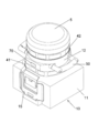
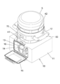
- FIG. 1 is an embodiment of an electric device according to the present invention, and is a perspective view showing an overall configuration.
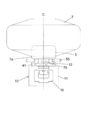
- FIG. 3 is a rear view of the embodiment in which a balloon is attached to the main body and the outlet is exposed.
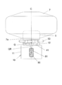
- FIG. 4 is a rear view of the embodiment in which the balloon is attached to the main body and the outlet is provided with the cover.
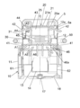
- FIG. 2B is a front view showing the state of intake and exhaust in the case of FIG. 2A.
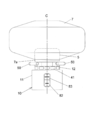
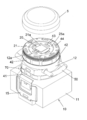
- FIG. 3 is a front view showing a state in which the light diffusion cover is provided on the main body in the embodiment. Also a perspective view.
- FIG. 3 is a front cross-sectional view showing an air flow when the light diffusion cover is provided on the main body. Similarly, it is a front sectional view showing the flow of drainage in the main body.
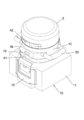
- FIG. 14 is a perspective view showing another embodiment of the electric device according to the present invention, in which a light diffusion cover is provided on the main body. The exploded perspective view.
- the balloon floodlight 1 includes a support leg portion 2 having a tripod structure, a main body portion 10 supported by a column 2a of the support leg portion 2, and a light-transmitting cover that covers the light emitting portion 20 of the main body portion 10.
- the diffusion cover 5 and the light-transmissive balloon 7 that covers the light diffusion cover 5 and a part of the main body 10 are provided.
- the main body portion 10 has a box-shaped lower main body housing 11 and a substantially cylindrical upper main body housing 12 integrally provided on the upper portion thereof with a slightly smaller diameter. As shown in FIG. 6 and the like, the main body portion 10 has a battery storage portion 14 for detachably storing a battery 13 (battery pack for electric tools) in a box-shaped lower main body housing 11.
- the battery storage portion 14 is opened on the side surface of the lower body housing 11, and the opening is closed by an opening/closing lid 15.
- An O-ring 16 for waterproofing is provided at the peripheral edge of the opening of the battery storage portion 14, and the opening of the battery storage portion 14 can be sealed watertight when the opening/closing lid 15 is closed.
- a support leg fixing nut 17 as a mounting portion for connecting and fixing the support leg 2 is fixed to the bottom surface of the lower body housing 11, and the support leg fixing nut 17 supports the support leg portion.
- Two columns 2a are screwed.
- the main body 10 is detachably connected to the support leg 2.
- a hook 18 as a suspending tool is attached to the bottom surface of the lower main body housing 11 so as to be capable of undulating. The hook 18 is provided for the convenience of transportation and suspension storage of the main body 10.
- the light emitting unit 20 includes a light emitting element substrate 21 that integrally includes a light emitting element group (LED group) 21a in which LEDs as light emitting elements are arranged in a plane.
- the heat sink 25 for cooling the light emitting unit 20 has a large number of cooling fins and a flat plate-shaped substrate holding unit 25a integrally, and the light emitting element substrate 21 is fixed on the substrate holding unit 25a of the heat sink 25. ..
- the substrate holding portion 25a is arranged so as to close the opening of the upper end surface of the substantially cylindrical upper main body housing 12, and serves as a partition portion that partitions a fan 30 and a light emitting portion 20 described later.
- the board holding portion 25a is screwed and fixed to the opening peripheral edge portion of the upper end surface of the upper main body housing 12.
- a motor-driven axial fan 30 that sends cooling air to the heat sink 25 is disposed below the heat sink 25.
- the axial fan 30 and a fan guide 31 surrounding the axial fan 30 are supported in the upper body housing 12. Since the battery 13 is arranged below the fan 30, the heat sink 25, the fan 30, and the battery 13 have the central axis C in the vertical direction (height direction) of the main body 10 (the same vertical line if the central axis is vertical). )It is above. That is, the heat sink 25, the fan 30, and the battery 13 (or the battery storage portion 14) are arranged in a straight line in the vertical direction of the main body portion 10.
- the intake port 41 and the exhaust port 42 are arranged on the outer peripheral surface of the main body part 10, that is, the outer peripheral surface of the upper main body housing 12, and the intake port 41 is lower than the exhaust port 42 in the height direction (vertical direction) of the main body part 10. In position. As shown in FIGS. 9 and 10, the intake port 41 is arranged at a height position below the fan 30, and the exhaust port 42 is arranged laterally of the heat sink 25. In addition, ventilation holes 43 and 44 are formed in the peripheral edges of the upper ends of the substrate holding portion 25a and the upper main body housing 12, respectively. A partition member 45 is arranged outside the fan guide 31 to partition the intake port 41 side and the exhaust port 42 side.
- Handles 50 are provided on both sides of the outer peripheral surface of the main body 10. That is, the pair of handles 50 are attached to the outer peripheral surface of the upper main body housing 12, respectively, and the handles 50 are arranged between the battery 13 and the heat sink 25 in the height direction of the main body 10. The position of the handle 50 is also between the intake port 41 and the exhaust port 42 in the height direction of the main body 10. The height position of the handle 50 is set to a position close to the height of the center of gravity of the main body portion 10 so that the main body portion 10 can be easily transported. As shown in FIG. 2B, the center of gravity Q is preferably provided near the central axis C between the handle 50 and the lower main body housing 11, specifically, the range of the dotted line QR in FIG. 2B.
- each handle 50 is made of an annular member and can be gripped as a handle, and also can be prevented from being stolen or can be engaged with a chain (not shown) at the time of using the hook 18 described later. ing.
- the light diffusing cover 5 as a light transmissive cover is made of a hard material such as resin having a predetermined light transmittance, and emits light from the light emitting element substrate 21 on which the light emitting element group 21a having a large number of LEDs arranged in a plane is mounted. It has a function to diffuse the whole amount.
- the shape of the light diffusion cover 5 is a flat cylindrical shape with the upper end surface closed, and a female screw portion 5a is formed on the inner peripheral surface of the cylindrical portion.
- the female screw portion 5a of the light diffusing cover 5 is screwed to the male screw portion 12a formed on the outer peripheral surface of the upper body of the upper body housing 12, so that the light diffusing cover 5 is detachably attached to the body portion 10 ( It is attached).
- a light emitting element drive circuit board 61 and a power supply circuit board 62 for lighting the light emitting element group 21 a on the light emitting element substrate 21 are housed in the lower main body housing 11.
- the light emitting element drive circuit board 61 is operated by the DC power source of the battery 13 to light up the light emitting element group 20 a on the light emitting element board 21.
- a commercial power input connector 80 is provided on the back surface of the lower main body housing 11 as shown in FIG. 2B so that it can be operated not only by the DC power source of the battery 13 but also by a commercial power source (for example, AC100V).
- the commercial power input from this connector is supplied to the power circuit board 62, and the DC output of the power circuit board 62 operates the light emitting element drive circuit board 61.
- the lower main body housing 11 is provided with an outlet 81 for commercial power supply output, and can supply electric power to other electric devices and the like (balloon floodlight).
- the commercial power input connector 80 and the commercial power output outlet 81 are provided with waterproof and dustproof covers 82 and 83 shown in FIG. 2C, which can be closed when not in use.
- the DC output of the power supply circuit board 62 can also be used for charging the battery 13, and when the commercial power supply is supplied to the commercial power input connector 80 and the balloon projector is not used, the battery 13 is charged.
- the battery 13 It may be charged, or may be charged when the power consumption of the balloon projector itself is low.
- the battery 13 is mounted in the battery housing portion 14 when the commercial power source fails, the light emitting element group 20a can be continuously lit by the DC power source from the battery 13.
- the blown air amount of the fan 30 may be increased or decreased according to the increase or decrease of the light amount.
- An operation panel 70 is provided on the outer peripheral surface of the main body 10.
- the operation panel 70 has a switch for turning on and off the balloon floodlight 1, adjusting the amount of light, and a switch for performing switching operation between battery drive and commercial power supply drive.
- the adjustment of the amount of light is performed by a toggle-type operation unit that sequentially repeats three steps of high, middle, and low each time the switch is pressed. Further, in the night-light mode or when the output is reduced during battery driving, only a part of the light emitting unit may be made to emit light in order to suppress power consumption, that is, to extend the battery driving time.
- the operation panel 70 is arranged on the outer peripheral surface of the upper main body housing 12 between the intake port 41 and the exhaust port 42 in the height direction of the main body 10.
- the balloon 7 is formed of a cloth material or the like having a required light transmittance and light scattering property (for example, cloth coated with a resin), and a substantially spherical or elliptical (flat sphere) shape or a cylindrical shape by blowing air into the inside. It swells to.
- the balloon 7 is open at the bottom, and a surface fastener that can be wound around and fixed to the outer peripheral surface of the upper main body housing 12 (an attachment portion for attaching the balloon 7 that is inflated by the cooling air from the exhaust port 42) around the opening.
- a mounting means 7a such as a string or a hook.
- the balloon 7 covers the light diffusion cover 5, which is the cover of the light emitting unit 20, and is detachably attached to the main body 10 so as to cover a part of the main body 10.
- the fixed position of the lower opening of the balloon 7 is the outer peripheral surface of the upper main body housing 12 between the intake port 41 and the exhaust port 42 and above the handle 50.
- the balloon 7 has a mounting means 7a such as a surface fastener around the lower opening, so that the balloon 7 is attached to the main body portion 10 so that a gap is not formed between the lower balloon opening and the outer peripheral surface of the upper main body housing 12 as much as possible. It is possible.
- the exhaust port 42 is opened in the balloon 7, and the balloon 7 can be inflated by the exhaust from the exhaust port 42. As shown in FIG.
- a slight gap G is provided between the fan guide 31 and the partition member 45 fixed in the upper main body housing 12 to partition the intake port 41 side and the exhaust port 42 side. It is provided.
- a lower fan guide 46 located below the fan guide 31 is fixed to the inner lower portion of the upper main body housing 12 on the intake port 41 side, and the lower fan guide 46 has an umbrella-shaped portion 46a connected to the lower edge of the intake port 41. is doing.
- the exhaust port 41 not only the exhaust port itself can discharge the rainwater from the inside by exhausting the exhaust air, but the rainwater entering from the exhaust port 42 as indicated by the arrow R1 drops on the partition member 45 and the partition member 45. Then, it descends to the umbrella-shaped portion 46a through the gap G between the fan guides 31 and is discharged to the outside from the intake port 41 as indicated by arrow R2. That is, the intake port 41 also serves as a drain port for drainage. Rainwater that has entered the intake port 41 is also transmitted to the outside of the intake port 41 along the umbrella-shaped portion 46a of the lower fan guide 46.
- the operation of the balloon floodlight 1 will be described.
- DC power is supplied to the light emitting element drive circuit board 61 from the commercial power source or the DC power source of the battery 13, and the light emitting element of the light emitting element substrate 21 included in the light emitting unit 20 is supplied.
- the group 20a emits light.
- the light from the light emitting element group 20a is diffused in the direction of 360 degrees by the light diffusion cover 5, and the balloon 7 is further illuminated to radiate the diffused light to the outside.
- the light emitting element substrate 21 generates heat when the light emitting element group 20a is turned on, but is cooled by radiating the heat sink 25, which is integrated with the substrate holding portion 25a on which the light emitting element substrate 21 is mounted, with cooling air from the fan 30. ..
- the remaining air flow passes through the ventilation hole 43 of the substrate holding portion 25a and enters the inside of the light diffusing cover 5 to cool the inside of the light diffusing cover 5 as shown by an arrow A3, and then an opening of the upper end surface of the upper body housing 12 is formed.
- Exhaust gas is exhausted into the balloon 7 from the exhaust port 42 through the vent hole 44 in the peripheral portion along the path indicated by the arrow A4. It is also possible to generate an air flow in the directions of arrows A5 and A6 by negative pressure due to the rotation of the fan 30, and to generate an air flow for cooling the battery 13, the light emitting element drive circuit board 61, and the power supply circuit board 62.
- the exhaust air discharged into the balloon 7 is warmed by the outside air passing through the heat sink 25 or the like, and the balloon 7 is inflated and warmed by the exhaust air. As a result, the flexibility of the balloon 7 is increased and it is possible to smoothly inflate it. When the balloon 7 is used, it is not always necessary to use the light diffusion cover 5.
- the air taken in from the intake port 41 is sent as cooling air to the heat sink 25 that cools the light emitting unit 20, and the air passing through the heat sink 25 is directed to the inside of the balloon 7.
- the balloon 7 is inflated by discharging from the opened exhaust port 42. Therefore, substantially all of the air flow from the fan 30 can be used for cooling the light emitting unit 20, and the cooling efficiency of the light emitting unit 20 is good.
- the light emitting unit 20 can achieve power saving and long life.
- the exhaust air discharged from the exhaust port 42 is warmer than the outside air, and the balloon 7 can be inflated and warmed.
- the expansion of the balloon 7 can be smoothed.
- the intake port 41 and the exhaust port 42 are arranged on the outer peripheral surface of the main body unit 10, the intake port 41 is located lower than the exhaust port 42 in the height direction of the main body unit 10, and the exhaust port 42 is the heat sink 25. Since it is arranged on the side of, the space can be saved without taking a complicated air passage structure.
- the exhaust port 42 is exposed to the outside air, but the rainwater that has infiltrated from the exhaust port is drained from the intake port 41 that also functions as a drain port, so the state in which the balloon 7 is removed It can be suitably used as a floodlight.
- the battery storage portion 14 of the main body portion 10 that detachably stores the battery 13 has a waterproof structure, and is particularly effective as a rain countermeasure when the balloon 7 is removed.
- the handle 50 is attached to the outer peripheral surface of the main body 10, and the handle 50 is located between the heat sink 25 and the battery 13 in the height direction of the main body 10 (in other words, between the intake port 41 and the exhaust port 42).
- the handle 50 is set at a position close to the height of the center of gravity of the main body portion 10, so that the main body portion 10 can be easily transported.
- the hook 18 as a suspending tool is attached to the bottom surface of the main body portion 10 so as to be capable of being raised and lowered, it is convenient for transporting or suspending and storing the main body portion 10.
- FIGS. 11 and 12 show another embodiment of the present invention.
- the structure of the light diffusion cover detachably attached to the main body 10 is different from that of the above-described embodiment.
- the light diffusion cover 5 of FIGS. 11 and 12 has an extension portion 5b extending downward. Then, when the light diffusion cover 5 is attached (screwed) to the upper end of the outer peripheral surface of the main body 10, the exhaust port 42 that opens to a position near the handle 50 is covered. This prevents the warm air exhausted from the exhaust port 42 from hitting the hand when the handle 50 is gripped by the hand.
- Other configurations are similar to those of the above-described embodiment.
- the light diffusing cover is used as the light transmissive cover in the above-described embodiment, a light converging cover or a light-transparent transparent cover can be used instead of the light diffusing cover 5.
- the light focusing cover has a lens portion that focuses light, and by using, for example, a convex lens or a Fresnel lens, it is suitable for use as a floodlight for a spotlight without using a balloon.
- a light-transmissive transparent cover it can be used as a floodlight that irradiates strong light in a specific direction by utilizing the light-straightness of the light emission of the LED included in the light emitting unit.
- a light diffusion cover, a light converging cover, and a light rectilinear transparent cover are prepared in advance as the light transmissive cover, and by replacing them with the main body, the function as a versatile floodlight can be exhibited. ..
- the LED is exemplified as the light emitting element of the light emitting portion, an organic EL light emitting body or the like can be used as the light emitting element.
- the projector is provided with a communication means so that it can be linked to a plurality of projectors, and when one of the linked projectors is turned on, the other projectors are similarly turned on. Alternatively, the illuminance and the like may be changed in the same manner.
- one remote controller may be used to control a plurality of projectors or one-to-one control. Is also good.
Landscapes
- Engineering & Computer Science (AREA)
- General Engineering & Computer Science (AREA)
- Arrangement Of Elements, Cooling, Sealing, Or The Like Of Lighting Devices (AREA)
- Non-Portable Lighting Devices Or Systems Thereof (AREA)
Abstract
投光機において、バルーンで覆われた発光部の冷却効率の向上を図る。発光部を有する本体部(10)と、本体部内に設けられるバッテリ(13)と、発光部を覆うとともに、本体部(10)の一部を覆うバルーン(7)と、発光部を冷却するためのヒートシンク(25)と、外気を取り込むための吸気口(41)と、吸気口(41)から取り込まれた空気をヒートシンクに送風するためのファン(30)と、ヒートシンクを通過した空気を排気するための排気口(42)とを備える。ヒートシンク、ファン及びバッテリは本体部の上下方向において一直線上に配置される。排気口(42)はバルーン(7)内に開口している。
Description
本発明は、発光部を有する電気機器に係り、とくにバルーン投光機として好適に使用可能な電気機器に関する。また、バルーンを装着して又はバルーン非装着で使用可能なバルーン着脱式投光器として好適に使用可能な電気機器に関する
従来、バルーン投光機の光源としてハロゲンランプが一般的に使用されてきたが、近年、省電力及び長寿命化の観点からLEDを光源とした発光部が使用されるようになってきている。
LED光源を用いた従来のバルーン投光機は、バルーン内にLED光源を配置し、バルーンを膨らませる空気流の一部がLED光源を冷却する構造であった。また、バルーン内にLED光源を配置し、LED光源から放射された光が直接バルーンの内側を照らす構造であった。
特許文献1は支持脚上の回転台にライトを設けた投光器の一例である。従来のバルーン投光機は、バルーン内に発光部を配置し、バルーンを膨らませる空気流の一部で発光部を冷却する構造であるため、発光部の冷却効率が良好とはいえないきらいがあった。また、バルーン内に発光部を配置し、発光部としてのLED光源から放射された光が直接バルーンの内側を照らす構造であり、LEDから放射される光は白熱灯やハロゲン灯と異なり指向性が高いため、バルーンの裏側全面に均等に当たり難く、バルーン全体を均等に光らせることが困難であった。特にLED光源に近い地面を照らす部分が暗くなるため、バルーンの上部に光を反射する材質とすることで地面側を明るくする方法もあるが、バルーン上部は光を遮るため、やはりバルーン全体を均等に光らせることはできなかった。また、バルーンを外し、手で持って使用することはできなかった。
本発明はこうした状況を認識してなされたものであり、第1の目的は、バルーンで覆われた発光部の冷却効率の向上を図ることのできる電気機器を提供することにある。第2の目的は、電気機器(投光機)のバルーンを外して、手で持って使用する場合に光拡散カバー等の光透過性カバーのみを取付けて使用することができるようにした電気機器(例えばバルーン着脱式投光機)を提供することにある。
本発明のある態様は電気機器である。この電気機器は、発光部を有する本体部と、前記本体部に設けられ、バッテリが着脱可能なバッテリ収納部と、前記発光部を覆うとともに、前記本体部の一部を覆うバルーンと、前記発光部を冷却するためのヒートシンクと、外気を取り込むための吸気口と、前記吸気口から取り込まれた空気を前記ヒートシンクに送風するためのファンと、前記ヒートシンクを通過した空気を排気するための排気口と、を備え、前記排気口は前記バルーン内で開口している。
前記ヒートシンク、前記ファン及び前記バッテリ収納部は前記本体部の上下方向において一直線上に配置されてもよい。
前記排気口から排出される空気によって前記バルーンを膨らませてもよい。
前記排気口から排出される空気によって前記バルーンを温めてもよい。
前記本体部の上下方向において、前記ヒートシンクの下方に前記ファンが位置し、前記ファンの下方に前記バッテリが位置しており、前記ヒートシンク、前記ファン及び前記バッテリが前記本体部の上下方向の中心軸上に配置されてもよい。
前記ファンの回転によって発生する空気流によって前記バッテリ及び前記ヒートシンクが冷却され、前記バッテリ及び前記ヒートシンクを冷却した空気が前記排気口から排出されるように構成してもよい。
前記吸気口及び前記排気口は前記本体部の外周面に配置され、前記本体部の高さ方向において、前記吸気口が前記排気口よりも低い位置にあってもよい。
前記排気口は前記ヒートシンクの側方に配置されてもよい。
前記本体部の外周面にハンドルが取り付けられ、前記ハンドルは前記本体部の高さ方向において、前記ヒートシンクと前記バッテリとの間に配置されてもよい。
前記本体部の外周面にハンドルが取り付けられ、前記ハンドルは前記本体部の高さ方向において、前記吸気口と前記排気口との間に配置されてもよい。
前記本体部の外周面に操作パネルが設けられており、前記操作パネルは前記本体部の高さ方向において、前記吸気口と前記排気口との間に配置されてもよい。
前記本体部は前記バッテリを充電できる、又は/及び、前記バッテリから他の電気機器に電力を供給できる構造であってもよい。
前記吸気口は、前記本体部の高さ方向において前記バッテリ収納部と前記ファンとの間に設けられてもよい。
前記排気口の下方に設けられている傘状部と、前記排気口及び前記吸気口が、排水用のドレン通路を兼ねてもよい。
前記発光部はLEDを有してもよい。
前記ファンと前記発光部との間を仕切る仕切り部を有し、前記仕切り部には、前記空気を通す為の通気孔を設けてもよい。
前記発光部を覆い、かつ前記本体部に着脱自在に設けられる硬質材料の光透過性カバーを備えてもよい。
前記本体部は、前記光透過性カバーを少なくとも覆う前記バルーンを着脱可能に取り付けるための取付け部を有してもよい。
外気を取り込むための吸気口と、前記ヒートシンクを通過した空気を排気するための排気口とが、前記本体部に設けられてもよい。
前記本体部にハンドルが取り付けられ、前記排気口は前記ハンドルの取付位置とは異なる高さ位置に設けられてもよい。
前記光透過性カバーは前記本体部の上下方向に延びる延長部を有し、前記延長部が前記ハンドルに近い位置の前記排気口を覆ってもよい。
前記本体部側には、前記光透過性カバーの内側空間に開口する通気孔が設けられ、前記ファンからの空気流の一部が前記通気孔を通り、前記光透過性カバーの内側空間を経て前記排気口から排気されてもよい。
前記本体部の底面には、支持脚部を連結するための取付部が設けられてもよい。
前記本体部の底面には、前記本体部を吊り下げるための吊り下げ具が設けられてもよい。
前記光透過性カバーが、光拡散カバー、光集束カバー又は光直進性の透明カバーであってもよい。
なお、以上の構成要素の任意の組合せ、本発明の表現を方法やシステムなどの間で変換したものもまた、本発明の態様として有効である。
本発明に係る電気機器によれば、バルーンで覆われる発光部の冷却を効率的に行うことが可能になる。また、バルーンを外して、手で持って使用する場合に光拡散カバー等の光透過性カバーのみを取付けて使用することが可能になる。また、光透過性カバーとして光拡散カバーを用いる場合、指向性の高いLEDにおいても放射された光を均一および効率的に利用することが可能になる。
以下、図面を参照しながら本発明の好適な実施の形態を詳述する。なお、各図面に示される同一または同等の構成要素、部材等には同一の符号を付し、適宜重複した説明は省略する。また、実施の形態は発明を限定するものではなく例示であり、実施の形態に記述されるすべての特徴やその組み合わせは必ずしも発明の本質的なものであるとは限らない。
図1から図10は、本発明に係る電気機器の実施の形態としてバルーン投光機(バルーン着脱式投光器)を示す。バルーン投光機1は、三脚構造を持つ支持脚部2と、支持脚部2の支柱2aで支持された本体部10と、本体部10が有する発光部20を覆う光透過性カバーとしての光拡散カバー5と、光拡散カバー5を覆うとともに本体部10の一部を覆う光透過性バルーン7とを備えている。
本体部10は、箱形の下部本体ハウジング11と、その上部にやや小径で一体的に設けられる略円筒状の上部本体ハウジング12とを有している。図6等に示すように、本体部10はバッテリ13(電動工具用電池パック)を着脱自在に収納するためのバッテリ収納部14を、箱形の下部本体ハウジング11内に有している。バッテリ収納部14は下部本体ハウジング11の側面に開口しており、その開口は開閉蓋15で閉じられるようになっている。バッテリ収納部14の開口の周縁部には防水のためのO-リング16が設けられており、開閉蓋15が閉じた状態ではバッテリ収納部14の開口を水密に封止できる。
図8に示すように、下部本体ハウジング11の底面には、支持脚部2を連結固定する取付部としての支持脚部固定ナット17が固定されており、支持脚部固定ナット17に支持脚部2の支柱2aが螺着される。支持脚部2に対して本体部10は着脱自在に連結される。また、下部本体ハウジング11の底面には、吊り下げ具としてのフック18が起伏自在に取り付けられている。フック18は本体部10の運搬や吊り下げ保管の便宜のために設けられている。
図7、図9及び図10に示すように、発光部20は、発光素子としてのLEDを多数面状配置した発光素子群(LED群)21aを一体に有する発光素子基板21を備える。発光部20を冷却するためのヒートシンク25は、冷却用フィンを多数有するとともに平板状の基板保持部25aを一体に有し、発光素子基板21はヒートシンク25の基板保持部25a上に固定されている。基板保持部25aは略円筒状の上部本体ハウジング12の上端面の開口を塞ぐ配置であり、後述のファン30と発光部20との間を仕切る仕切り部となる。基板保持部25aは上部本体ハウジング12の上端面の開口周縁部にネジ止め固定される。ヒートシンク25の下方位置にはヒートシンク25に冷却用空気を送り込むモータ駆動の軸流ファン30が配置されている。軸流ファン30及びこれを取り囲むファンガイド31は上部本体ハウジング12内に支持されている。ファン30の下方位置にバッテリ13が配置されているから、ヒートシンク25、ファン30及びバッテリ13は本体部10の上下方向(高さ方向)の中心軸C(中心軸が鉛直であれば同一鉛直線)上にある。すなわち、ヒートシンク25、ファン30及びバッテリ13(又はバッテリ収納部14)は本体部10の上下方向において一直線上に配置されている。
本体部10の外周面、つまり上部本体ハウジング12の外周面に吸気口41及び排気口42が配置され、本体部10の高さ方向(上下方向)において、吸気口41が排気口42よりも低い位置にある。図9及び図10に示す通り、吸気口41はファン30よりも下方の高さ位置で、排気口42はヒートシンク25の側方に配置されている。また、基板保持部25a及び上部本体ハウジング12の上端面の開口周縁部に通気孔43,44がそれぞれ形成されている。また、吸気口41側と排気口42側とを仕切るために仕切り部材45がファンガイド31の外側に配置されている。
本体部10の外周面の両側にハンドル50が設けられている。つまり、一対のハンドル50は上部本体ハウジング12の外周面にそれぞれ取り付けられ、ハンドル50は本体部10の高さ方向において、バッテリ13とヒートシンク25との間に配置されている。このハンドル50の位置は、本体部10の高さ方向において、吸気口41と排気口42との間でもある。ハンドル50の高さ位置は、本体部10の重心の高さに近い位置に設定され、本体部10の運搬が容易となるようにしている。図2Bに示すように、前記重心Qは、好ましくは、ハンドル50と下部本体ハウジング11の間の中心軸C付近に設けられるようにするのが良く、具体的には図2Bの点線QRの範囲内に位置するとよい。こうすることで、ハンドル50を持った時のバランス(安定感)が良くなる。また、それぞれのハンドル50は、円環状の部材にて構成されており、ハンドルとして把持できる他、盗難防止、あるいは後述するフック18の使用時における鎖(図示せず)で係合できるようになっている。
光透過性カバーとしての光拡散カバー5は、所定の光透過率を有する樹脂等の硬質材料からなり、LEDを多数面状配置した発光素子群21aを搭載した発光素子基板21の発光を周囲360度全体に拡散させる機能を有する。光拡散カバー5の形状は上端面が閉じた偏平円筒状であり、円筒状部分の内周面に雌螺子部5aが形成されている。上部本体ハウジング12の上端部外周面に形成された雄螺子部12aに光拡散カバー5の雌螺子部5aが螺合することにより、光拡散カバー5は本体部10に着脱自在に装着される(取り付けられる)。
下部本体ハウジング11内には、発光素子基板21上の発光素子群21aを点灯させるための発光素子駆動回路基板61及び電源回路基板62が収納されている。バッテリ収納部14にバッテリ13が装着されたバッテリ使用時は、バッテリ13の直流電源で発光素子駆動回路基板61が動作し、発光素子基板21上の発光素子群20aを点灯させる。図示しないが、バッテリ13の直流電源だけでなく、商用電源(例えばAC100V)でも動作可能なように下部本体ハウジング11の背面に、図2Bのように商用電源入力用コネクタ80が設けられている。このコネクタからの商用電源入力が電源回路基板62に供給され、電源回路基板62の直流出力で発光素子駆動回路基板61を作動させるようになっている。更に、下部本体ハウジング11には商用電源出力用コンセント81が設けられていて、他の電気機器等(バルーン投光機)に電力を供給することができる。これらの商用電源入力用コネクタ80、商用電源出力用コンセント81には、図2Cに示す防水、防塵の為のカバー82、83が設けられていて、使用しないときには塞ぐことができる。なお、電源回路基板62の直流出力はバッテリ13の充電にも使用でき、商用電源入力用コネクタ80に商用電源が供給されていて、バルーン投光機が使用されていない時などに、バッテリ13に充電するようにしても良いし、バルーン投光機自体の消費電力が少ない時に、充電するようにしても良い。こうすることで、商用電源が停電になったときに、バッテリ13がバッテリ収納部14に装着されていれば、バッテリ13からの直流電源で発光素子群20aの点灯を継続させることができる。また、操作パネル70で発光部20の光量が調節可能な場合、光量に増減に対応させてファン30の送風量を増減してもよい。さらに、充電が完了しているバッテリ(電動工具用電池パック)13を取り出し、他の電気機器や、電動工具(例えば、ドライバーやインパクトレンチ等)に使用することもできる。
本体部10の外周面に操作パネル70が設けられている。操作パネル70はバルーン投光機1の点灯、消灯、光量の調整を行うスイッチや、バッテリ駆動と商用電源駆動との切り替え操作等を行うためのスイッチを有している。なお、光量の調整は、例えば、スイッチを押す毎に、高、中、低の3段階を順次繰り返すようなトグル型の操作部になっている。更に、常夜灯モードや、バッテリ駆動における出力低下時などで、消費電力を抑制、すなわち、バッテリ駆動時間の延長化のために、発光部の一部分のみを発光させるようにしても良い。操作パネル70は本体部10の高さ方向において、吸気口41と排気口42との間の上部本体ハウジング12外周面に配置されている。
バルーン7は所要の光透過性及び光散乱性を有する布材等(例えば布に樹脂を塗布したもの)で形成され、内部に空気を送り込むことで略球状あるいは楕円(偏平球体)状や円筒状に膨らむものである。バルーン7は下部に開口しており、その開口の周囲に、上部本体ハウジング12の外周面(排気口42からの冷却風で膨らむバルーン7を取付けるための取付け部)に巻付け固定可能な面ファスナー、ひも、フック等の装着手段7aを有している。バルーン7は発光部20のカバーである光拡散カバー5を覆うとともに、本体部10の一部を覆うように本体部10に着脱自在に装着される。バルーン7の下部開口の固定位置は、吸気口41と排気口42の間でハンドル50よりも上の上部本体ハウジング12外周面である。バルーン7は下部開口の周囲に面ファスナー等の装着手段7aを有することで、バルーン下部開口と上部本体ハウジング12外周面との間に、なるべく隙間が生じないようにバルーン7を本体部10に取り付けることが可能である。また、排気口42はバルーン7内で開口しており、排気口42からの排気でバルーン7を膨らませることができる。図3のように、吸気口41から本体部10内に吸入された外気(矢印IN)は、本体部10内のヒートシンク25や光拡散カバー5の内側を通過し、それらの熱を奪って温まった排気(矢印OUT)となって排気口42からバルーン7内に排気される。なお、冷却用空気の流れは後で詳述する。
バルーン7を外した状態で投光機として使用する場合、吸気口41だけでなく排気口42も外気にさらされる。つまり、吸気口41及び排気口42から入った雨水のドレン対策が必要となる。このため、図10に示すように、吸気口41側と排気口42側とを仕切るために上部本体ハウジング12内に固定される仕切り部材45と、ファンガイド31との間に僅かな隙間Gを設けている。吸気口41側にはファンガイド31の下方に位置する下部ファンガイド46が上部本体ハウジング12の内側下部に固定され、下部ファンガイド46は吸気口41の下縁に接続する傘状部46aを有している。従って、排気口はそれ自体が内部から排気風の排気によって雨水を排出可能であるのみならず、排気口42からの矢印R1のように入った雨水は仕切り部材45上に滴下し、仕切り部材45と、ファンガイド31間の隙間Gを経て傘状部46aに降下し、矢印R2のように吸気口41から外部に排出される。つまり、吸気口41は排水用のドレン口を兼ねている。吸気口41に浸入した雨水も下部ファンガイド46の傘状部46a上を伝わって吸気口41の外部に排出される。なお、バルーン7を装着した場合、湿度が高い環境では、吸気された空気に含まれる水分が光源から離れたバルーンの頂部等において結露し、排気口に向かって滴下する場合があるが、この場合も、同様に排気口42から仕切り部材45や傘状部46aを介して吸気口41から排気される。
以上の実施の形態に示すバルーン投光機1の動作について説明する。操作パネル70でバルーン投光機1の点灯操作を行えば、商用電源又はバッテリ13の直流電源により発光素子駆動回路基板61に直流電力が供給され、発光部20が有する発光素子基板21の発光素子群20aが発光する。発光素子群20aからの光が光拡散カバー5で360度方向に拡散され、さらにバルーン7を光らせて外部に拡散光を照射する。発光素子群20aの点灯により発光素子基板21は発熱するが、発光素子基板21が載置された基板保持部25aが一体のヒートシンク25を、ファン30からの冷却風によって放熱することで冷却される。
図9で吸気口41から取り込まれた外気が本体部10内のヒートシンク25や光拡散カバー5内を通って排気口42から排気として排出されるまでの経路を説明する。ファン30が回転することで矢印A1~A4の方向に空気流が発生する。矢印A1のように吸気口41内に取り込まれた外気は、ファン30で矢印A2,A3のように冷却用空気としてヒートシンク25に送風される。ヒートシンク25を通過した空気流の過半は矢印A2,A4の経路でヒートシンク25の側方に位置する排気口42からバルーン7内に排気として排出される。残りの空気流は矢印A3のように基板保持部25aの通気孔43を通過して光拡散カバー5の内側に入って光拡散カバー5内を冷却してから上部本体ハウジング12の上端面の開口周縁部の通気孔44を経て矢印A4の経路で排気口42からバルーン7内に排気として排出される。なお、ファン30が回転することによる負圧で矢印A5,A6方向の空気流が生じ、バッテリ13や発光素子駆動回路基板61、電源回路基板62を冷却する空気流を発生させることもできる。
バルーン7内に排出される排気は、外気がヒートシンク25等を通過することで温められており、バルーン7は排気により膨らむとともに温められる。これによって、バルーン7の柔軟性が高まり、円滑に膨張させることが可能である。なお、バルーン7を使用する場合は、必ずしも光拡散カバー5を使用する必要は無い。
本実施の形態によれば、下記の効果を奏することができる。
(1) 本体部10内のファン30の回転により、吸気口41から取り込まれた空気を発光部20を冷却するヒートシンク25に冷却風として送出し、ヒートシンク25を通過した空気をバルーン7の内側に開口した排気口42から排出してバルーン7を膨らませる構成である。このため、実質的にファン30による空気流の全てを発光部20の冷却に利用でき、発光部20の冷却効率が良い。
(2) 発光部20は多数のLEDを面状に配置した発光素子基板21を用いることで、省電力及び長寿命化を図ることができる。
(3) 排気口42から排出される排気は外気よりも温かくなっており、バルーン7を膨らませるとともに温めることが可能である。バルーン7の膨張を円滑化できる。
(4) ヒートシンク25、ファン30及びバッテリ13が本体部10の上下方向の中心軸上に配置されているため、重心バランスが向上し、本体部10の支持脚部2による支持も安定する。
(5) 吸気口41及び排気口42は本体部10の外周面に配置され、本体部10の高さ方向において、吸気口41が排気口42よりも低い位置にあり、排気口42はヒートシンク25の側方に配置されているから、複雑な風路構成をとらず省スペース化を図ることができる。
(6) バルーン7を装着しないで使用した場合、排気口42が外気にさらされるが、排気口から浸入した雨水がドレン口を兼ねた吸気口41から排水されるから、バルーン7を外した状態での投光機として好適に使用できる。また、バッテリ13を着脱自在に収納する本体部10のバッテリ収納部14は防水構造であり、とくにバルーン7を外したときの雨対策として有効である。
(7) 本体部10の外周面にハンドル50が取り付けられ、ハンドル50は本体部10の高さ方向において、ヒートシンク25とバッテリ13との間(換言すれば、吸気口41と排気口42との間)に配置されているから、ハンドル50は本体部10の重心の高さに近い位置に設定されることになり、本体部10の運搬が容易となる。
(8) 本体部10の底面には、吊り下げ具としてのフック18が起伏自在に取り付けられているから、本体部10の運搬や吊り下げ保管に便利である。
(9) 光透過性カバーとして光拡散カバー5を用いることで、指向性の高いLEDにおいても放射された光を均一および効率的に利用することが可能になる。
図11及び図12は本発明の他の実施の形態を示す。この場合、本体部10に着脱自在に装着される光拡散カバーの構造が前述の実施の形態とは異なっている。図11及び図12の光拡散カバー5は下方に延在した延長部5bを有している。そして、光拡散カバー5を本体部10の外周面上端部に装着(螺着)したときに、ハンドル50に近い位置に開口する排気口42を覆うようになっている。これにより、手でハンドル50を握った時に排気口42から排気される暖かい風が手に当たらないようできる。その他の構成は前述の実施の形態と同様である。
バルーンを使用しない投光機として用いる場合、ハンドル50の付近が排気で熱くなりにくいため、発光部20の点灯中であっても、ハンドル50を作業者が把持して投光機の位置、向き等を変更できる。
以上、実施の形態を例に本発明を説明したが、実施の形態の各構成要素や各処理プロセスには請求項に記載の範囲で種々の変形が可能であることは当業者に理解されるところである。以下、変形例について触れる。
前述の実施の形態では、光透過性カバーとして光拡散カバーを用いたが、光拡散カバー5の代わりに光集束カバー又は光直進性の透明カバーを用いることができる。光集束カバーは光を集束するレンズ部を有するもので、例えば凸状レンズやフレネルレンズ等を用いることで、バルーンを用いないでスポットライト用投光機として利用するのに適する。また、光直進性の透明カバーの場合、発光部が有するLEDの発光の光直進性を利用することで、特定方向に強力な光を照射する投光機として利用することができる。予め、光透過性カバーとして光拡散カバー、光集束カバー及び光直進性の透明カバーを用意しておき、それらを本体部に対して付け替えることで、多用途な投光機としての機能を発揮できる。
発光部の発光素子としてLEDを例示したが、有機EL発光体等を発光素子として使用可能である。更に、投光機には通信手段を設け、複数の投光機とリンクできるようにしておき、リンクしている投光器の内の一台がオンされたら、他の投光機も同様に点灯したり、照度等も同様に変化したりするようにしておいても良く、さらに1台のリモコンで、複数台の投光機をコントロールできるようにしても良いし、一対一でコントロールできるようにしても良い。
1…バルーン投光機、2…支持脚部、5…光拡散カバー、5a…雌螺子部、5b…延長部、7…光透過性バルーン、10…本体部、13…バッテリ、14…バッテリ収納部、15…開閉蓋、18…フック、20…発光部、21…発光素子基板、25…ヒートシンク、25a…基板保持部、30…軸流ファン、41…吸気口、42…排気口、43,44…通気孔、50…ハンドル、61…発光素子駆動回路基板、62…電源回路基板、70…操作パネル。
Claims (15)
- 発光部を有する本体部と、
前記本体部に設けられ、バッテリが着脱可能なバッテリ収納部と、
前記発光部を覆うとともに、前記本体部の一部を覆うバルーンと、
前記発光部を冷却するためのヒートシンクと、
外気を取り込むための吸気口と、
前記吸気口から取り込まれた空気を前記ヒートシンクに送風するためのファンと、
前記ヒートシンクを通過した空気を排気するための排気口と、を備え、
前記ヒートシンク、前記ファン及び前記バッテリ収納部は前記本体部の上下方向において一直線上に配置され、
前記排気口は前記バルーン内で開口しており、
前記排気口から排出される空気によって前記バルーンを膨らませる、電気機器。 - 前記排気口から排出される空気によって前記バルーンを温める、請求項1に記載の電気機器。
- 前記本体部の上下方向において、前記ヒートシンクの下方に前記ファンが位置し、前記ファンの下方に前記バッテリが位置しており、前記ヒートシンク、前記ファン及び前記バッテリが前記本体部の上下方向の中心軸上に配置されている、請求項1又は2に記載の電気機器。
- 前記ファンの回転によって発生する空気流によって前記バッテリ及び前記ヒートシンクが冷却され、
前記バッテリ及び前記ヒートシンクを冷却した空気が前記排気口から排出される、請求項1乃至3のいずれか一項に記載の電気機器。 - 前記吸気口及び前記排気口は、次の(1)~(3)の少なくとも1つを満足するように配置される、請求項1乃至4のいずれか一項に記載の電気機器。
(1)前記吸気口及び前記排気口は、前記本体部の外周面に配置され、前記本体部の高さ方向において、前記吸気口が前記排気口よりも低い位置にある。
(2)前記排気口は、前記ヒートシンクの側方に配置されている。
(3)前記吸気口は、前記本体部の高さ方向において前記バッテリ収納部と前記ファンとの間に設けられている。 - 前記本体部の外周面にハンドルが取り付けられ、前記ハンドルは前記本体部の高さ方向において、前記ヒートシンクと前記バッテリとの間、又は、前記吸気口と前記排気口との間に配置されている、請求項5に記載の電気機器。
- 前記本体部の外周面に操作パネルが設けられており、前記操作パネルは前記本体部の高さ方向において、前記吸気口と前記排気口との間に配置されている、請求項5又は6に記載の電気機器。
- 前記本体部は前記バッテリを充電できる、又は/及び、前記バッテリから他の電気機器に電力を供給できる、請求項1乃至7のいずれか一項に記載の電気機器。
- 前記排気口の下方に設けられている傘状部と、前記排気口及び前記吸気口が、排水用のドレン通路を兼ねている、請求項1乃至8のいずれか一項に記載の電気機器。
- 前記ファンと前記発光部との間を仕切る仕切り部を有し、前記仕切り部には、前記空気を通す為の通気孔が設けられる、請求項1乃至9のいずれか一項に記載の電気機器。
- 前記発光部を覆い、かつ前記本体部に着脱自在に設けられる硬質材料の光透過性カバーを備え、
前記本体部は、前記光透過性カバーを覆う前記バルーンを着脱可能に取り付けるための取付け部を有する、請求項1乃至10のいずれか一項に記載の電気機器。 - 前記光透過性カバーは前記本体部の上下方向に延びる延長部を有し、
前記延長部は前記本体部に取り付けられたハンドルに近い位置の前記排気口を覆う、請求項11に記載の電気機器。 - 前記本体部には、前記光透過性カバーの内側空間に開口する通気孔が設けられ、
前記ファンからの空気流の一部が前記通気孔を通り、前記光透過性カバーの内側空間を経て前記排気口から排気される、請求項11又は12に記載の電気機器。 - 前記本体部の底面には、支持脚部を連結するための取付部と前記本体部を吊り下げるための吊り下げ具の少なくとも一方が設けられている、請求項1乃至13のいずれか一項に記載の電気機器。
- 前記光透過性カバーが、光拡散カバー、光集束カバー又は光直進性の透明カバーである、請求項11乃至14のいずれか一項に記載の電気機器。
Priority Applications (1)
| Application Number | Priority Date | Filing Date | Title |
|---|---|---|---|
| JP2020559782A JP7127698B2 (ja) | 2018-12-07 | 2019-10-25 | 電気機器 |
Applications Claiming Priority (4)
| Application Number | Priority Date | Filing Date | Title |
|---|---|---|---|
| JP2018-230074 | 2018-12-07 | ||
| JP2018230074 | 2018-12-07 | ||
| JP2018230075 | 2018-12-07 | ||
| JP2018-230075 | 2018-12-07 |
Publications (1)
| Publication Number | Publication Date |
|---|---|
| WO2020116049A1 true WO2020116049A1 (ja) | 2020-06-11 |
Family
ID=70974588
Family Applications (1)
| Application Number | Title | Priority Date | Filing Date |
|---|---|---|---|
| PCT/JP2019/041964 Ceased WO2020116049A1 (ja) | 2018-12-07 | 2019-10-25 | 電気機器 |
Country Status (2)
| Country | Link |
|---|---|
| JP (1) | JP7127698B2 (ja) |
| WO (1) | WO2020116049A1 (ja) |
Cited By (1)
| Publication number | Priority date | Publication date | Assignee | Title |
|---|---|---|---|---|
| US20240176212A1 (en) * | 2022-11-25 | 2024-05-30 | Guangdong Sirui Optical Co., Ltd. | Inflatable lamp |
Citations (4)
| Publication number | Priority date | Publication date | Assignee | Title |
|---|---|---|---|---|
| JP2008542976A (ja) * | 2005-03-31 | 2008-11-27 | 新灯源科技有限公司 | 高効率の熱放散を備えた高出力ledを使用した照明機器 |
| US20110090677A1 (en) * | 2009-02-13 | 2011-04-21 | Frontier Lighting Technologies, Llc | Collapsible lighting device |
| JP2013020953A (ja) * | 2011-06-17 | 2013-01-31 | Light Boy Co Ltd | バルーン型投光機 |
| CN204134158U (zh) * | 2014-09-04 | 2015-02-04 | 明达实业(厦门)有限公司 | 一种带有灯光的吹气球 |
-
2019
- 2019-10-25 WO PCT/JP2019/041964 patent/WO2020116049A1/ja not_active Ceased
- 2019-10-25 JP JP2020559782A patent/JP7127698B2/ja active Active
Patent Citations (4)
| Publication number | Priority date | Publication date | Assignee | Title |
|---|---|---|---|---|
| JP2008542976A (ja) * | 2005-03-31 | 2008-11-27 | 新灯源科技有限公司 | 高効率の熱放散を備えた高出力ledを使用した照明機器 |
| US20110090677A1 (en) * | 2009-02-13 | 2011-04-21 | Frontier Lighting Technologies, Llc | Collapsible lighting device |
| JP2013020953A (ja) * | 2011-06-17 | 2013-01-31 | Light Boy Co Ltd | バルーン型投光機 |
| CN204134158U (zh) * | 2014-09-04 | 2015-02-04 | 明达实业(厦门)有限公司 | 一种带有灯光的吹气球 |
Cited By (2)
| Publication number | Priority date | Publication date | Assignee | Title |
|---|---|---|---|---|
| US20240176212A1 (en) * | 2022-11-25 | 2024-05-30 | Guangdong Sirui Optical Co., Ltd. | Inflatable lamp |
| US12072608B2 (en) * | 2022-11-25 | 2024-08-27 | Guangdong Sirui Optical Co., Ltd. | Inflatable lamp |
Also Published As
| Publication number | Publication date |
|---|---|
| JP7127698B2 (ja) | 2022-08-30 |
| JPWO2020116049A1 (ja) | 2021-10-14 |
Similar Documents
| Publication | Publication Date | Title |
|---|---|---|
| US8021027B2 (en) | LED based acorn style luminaire | |
| KR101092233B1 (ko) | 분리형 경관조명기구 | |
| WO2006065589A8 (en) | Inspection light assembly | |
| CN104685289A (zh) | 多方向的灯组件 | |
| US20130308310A1 (en) | Led lamp and method | |
| US20060146523A1 (en) | Fluorescent flood light | |
| KR101098001B1 (ko) | 엘이디 모듈의 탈착 및 분리 가능한 엘이디 전구 | |
| JP2004247298A (ja) | 旋回可能な光学系を備える懐中電燈 | |
| KR20080005009U (ko) | 엘이디를 사용하는 매입등용 하우징 | |
| JP7127698B2 (ja) | 電気機器 | |
| JP2017139204A (ja) | 投光器 | |
| US7645045B2 (en) | Tripod for camera | |
| KR101128822B1 (ko) | 엘이디 램프 | |
| CN203797405U (zh) | 模块化发光装置 | |
| CN102483194B (zh) | 移动式照明装置 | |
| CN203671271U (zh) | 一种手持式led应急灯 | |
| KR200459787Y1 (ko) | 차량용 조명기구 고정구조 | |
| CN210568042U (zh) | 灯具 | |
| CN110307483B (zh) | 多功能工作灯 | |
| US20140268791A1 (en) | Lighting fixtures for solid-state light sources | |
| CN206555857U (zh) | 遥控吸顶灯 | |
| CN215215792U (zh) | 一种结合led与激光模组的一体式照明灯具 | |
| CN218720732U (zh) | 一种带可伸缩灯管的手电筒 | |
| CN218820131U (zh) | 旋转照明结构及灯具 | |
| KR20110099869A (ko) | 무대 조명장치 |
Legal Events
| Date | Code | Title | Description |
|---|---|---|---|
| 121 | Ep: the epo has been informed by wipo that ep was designated in this application |
Ref document number: 19891971 Country of ref document: EP Kind code of ref document: A1 |
|
| ENP | Entry into the national phase |
Ref document number: 2020559782 Country of ref document: JP Kind code of ref document: A |
|
| NENP | Non-entry into the national phase |
Ref country code: DE |
|
| 122 | Ep: pct application non-entry in european phase |
Ref document number: 19891971 Country of ref document: EP Kind code of ref document: A1 |