WO2020115833A1 - 車両の旋回制御方法および車両の旋回制御装置 - Google Patents
車両の旋回制御方法および車両の旋回制御装置 Download PDFInfo
- Publication number
- WO2020115833A1 WO2020115833A1 PCT/JP2018/044674 JP2018044674W WO2020115833A1 WO 2020115833 A1 WO2020115833 A1 WO 2020115833A1 JP 2018044674 W JP2018044674 W JP 2018044674W WO 2020115833 A1 WO2020115833 A1 WO 2020115833A1
- Authority
- WO
- WIPO (PCT)
- Prior art keywords
- vehicle
- driving force
- turning control
- turning
- control method
- Prior art date
- Legal status (The legal status is an assumption and is not a legal conclusion. Google has not performed a legal analysis and makes no representation as to the accuracy of the status listed.)
- Ceased
Links
Images




Classifications
-
- B—PERFORMING OPERATIONS; TRANSPORTING
- B60—VEHICLES IN GENERAL
- B60L—PROPULSION OF ELECTRICALLY-PROPELLED VEHICLES; SUPPLYING ELECTRIC POWER FOR AUXILIARY EQUIPMENT OF ELECTRICALLY-PROPELLED VEHICLES; ELECTRODYNAMIC BRAKE SYSTEMS FOR VEHICLES IN GENERAL; MAGNETIC SUSPENSION OR LEVITATION FOR VEHICLES; MONITORING OPERATING VARIABLES OF ELECTRICALLY-PROPELLED VEHICLES; ELECTRIC SAFETY DEVICES FOR ELECTRICALLY-PROPELLED VEHICLES
- B60L15/00—Methods, circuits, or devices for controlling the traction-motor speed of electrically-propelled vehicles
- B60L15/20—Methods, circuits, or devices for controlling the traction-motor speed of electrically-propelled vehicles for control of the vehicle or its driving motor to achieve a desired performance, e.g. speed, torque, programmed variation of speed
-
- B—PERFORMING OPERATIONS; TRANSPORTING
- B60—VEHICLES IN GENERAL
- B60L—PROPULSION OF ELECTRICALLY-PROPELLED VEHICLES; SUPPLYING ELECTRIC POWER FOR AUXILIARY EQUIPMENT OF ELECTRICALLY-PROPELLED VEHICLES; ELECTRODYNAMIC BRAKE SYSTEMS FOR VEHICLES IN GENERAL; MAGNETIC SUSPENSION OR LEVITATION FOR VEHICLES; MONITORING OPERATING VARIABLES OF ELECTRICALLY-PROPELLED VEHICLES; ELECTRIC SAFETY DEVICES FOR ELECTRICALLY-PROPELLED VEHICLES
- B60L9/00—Electric propulsion with power supply external to the vehicle
- B60L9/16—Electric propulsion with power supply external to the vehicle using AC induction motors
- B60L9/18—Electric propulsion with power supply external to the vehicle using AC induction motors fed from DC supply lines
-
- Y—GENERAL TAGGING OF NEW TECHNOLOGICAL DEVELOPMENTS; GENERAL TAGGING OF CROSS-SECTIONAL TECHNOLOGIES SPANNING OVER SEVERAL SECTIONS OF THE IPC; TECHNICAL SUBJECTS COVERED BY FORMER USPC CROSS-REFERENCE ART COLLECTIONS [XRACs] AND DIGESTS
- Y02—TECHNOLOGIES OR APPLICATIONS FOR MITIGATION OR ADAPTATION AGAINST CLIMATE CHANGE
- Y02T—CLIMATE CHANGE MITIGATION TECHNOLOGIES RELATED TO TRANSPORTATION
- Y02T10/00—Road transport of goods or passengers
- Y02T10/60—Other road transportation technologies with climate change mitigation effect
- Y02T10/72—Electric energy management in electromobility
Definitions
- the present invention relates to a vehicle turning control method and a vehicle turning control device.
- Patent Document 1 discloses a technique for suppressing tuck-in and stabilizing vehicle turning by performing regenerative braking by a motor generator of rear wheels when a braking force is generated by engine braking force and tuck-in occurs. ing.
- An object of the present invention is to provide a vehicle that can be controlled in the oversteer direction.
- a turning control method for a vehicle and a turning control device for a vehicle according to the present invention are vehicles having a first drive source that drives left and right front wheels and a second drive source that drives left and right rear wheels. When the vehicle turns forward by acceleration, the left and right front wheels are driven and the left and right rear wheels are braked.
- the amount of oversteer can be controlled and the turning radius can be reduced, so that the turning radius of the vehicle can be made smaller and the turning performance of the vehicle can be improved.
- FIG. 1 is a schematic diagram showing a drive system and a control device of a vehicle of Embodiment 1.
- FIG. 5 is a flowchart showing a flow of processing of turning control according to the first embodiment.
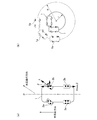
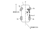
- (A) is an explanatory view of turning control of a front wheel and a rear wheel during forward turning by acceleration according to the first embodiment
- (b) is a schematic diagram showing turning radii of the first embodiment and a comparative example.
- 3 is an explanatory diagram of turning control of a front wheel and a rear wheel during a reverse turn of the first embodiment.
- FIG. 3 is an example of a characteristic diagram showing a relationship between a steering angle during forward turning by acceleration of turning control of the first embodiment and driving forces of front wheels and rear wheels.
- FIG. 3 is an example of a characteristic diagram showing a relationship between a driver-requested driving force for turning control of the first embodiment and driving forces for front wheels and rear wheels.
- FIG. 9 is an example of a characteristic diagram showing a relationship between a driver-requested driving force for turning control and driving forces for front wheels and rear wheels according to the second embodiment.
- FIG. 11 is an example of a characteristic diagram showing a relationship between a driver-requested driving force for turning control and driving forces for front wheels and rear wheels according to the third embodiment.
- FIG. 1 is a schematic diagram showing a vehicle drive system and a control device of a first embodiment.
- the vehicle 1 according to the first embodiment includes a control device 4 including an electric motor 2 for running front wheels, a front left wheel 2a, a front right wheel 2b, an electric motor 3 for running rear wheels, a rear left wheel 3a, a rear right wheel 3b, and a turning control means 4a.
- the control device 4 acquires information from the steering angle sensor 5, the accelerator pedal sensor 6, the brake pedal sensor 7, the vehicle speed sensor 8, and the wheel load sensor 9 that measures the wheel load of each wheel.
- the axis P indicates the vehicle center axis in the vehicle front-rear direction.
- FIG. 2 is a flowchart showing a flow of processing of turning control according to the first embodiment. This flowchart is repeatedly executed at a predetermined calculation cycle.
- step S1 it is determined from the information from the steering angle sensor 5 whether the vehicle is turning. When the vehicle is turning, the process proceeds to step S2, and when the vehicle is not turning, the process returns to step S1.
- step S2 it is determined from the information from the accelerator pedal sensor 6 and the brake pedal sensor 7 whether the driver is stepping on the accelerator pedal or the brake pedal (ON). When the driver depresses the accelerator pedal or the brake pedal (ON), the process proceeds to step S3, and when the driver does not depress the accelerator pedal or the brake pedal (OFF), the process proceeds to step S6.
- step S3 it is determined whether or not the required driving force of the driver based on the information from the accelerator pedal sensor 6 is less than or equal to a predetermined driving force that is less than the vehicle rated driving force.
- the predetermined driving force is set such that the set front wheel driving force does not exceed 100% of the vehicle rated driving force. For example, the driving force is 70% to 80% of the vehicle rated driving force. If the driver's required driving force is less than or equal to the predetermined driving force less than the vehicle rated driving force, the process proceeds to step S4. If the driver's required driving force is not less than or equal to the predetermined driving force less than the vehicle rated driving force, step Return to S1.
- step S4 the wheel load of each wheel is calculated from the information from the wheel load sensor 9.
- step S5 depending on the steering angle based on the information from the steering angle sensor 5 and the wheel load of each wheel, the left and right front wheels 2a, 2b during forward turning due to deceleration or backward turning, or forward turning due to acceleration At this time, the regenerative forces of the left and right rear wheels 3a, 3b are calculated.
- step S6 the left and right front wheels 2a, 2b or the front acceleration are used during forward turning or backward turning due to deceleration so that the sum of the driving forces of the left and right front and rear wheels 2a, 2b, 3a, 3b becomes the creep torque.
- the regenerative force corresponding to the steering angles of the left and right rear wheels 3a, 3b is calculated.
- step S7 the turning operation by the turning control means 4a is executed according to the calculated regenerative force.
- the left and right front wheels 2a, 2b and the left and right rear wheels 3a, 3b are controlled by the same positive and negative driving force. As a result, the vehicle 1 can be turned in a stable state.
- FIG. 3A is an explanatory diagram of the turning control of the front wheels and the rear wheels during forward turning by acceleration according to the first embodiment
- FIG. 3B is a schematic diagram showing the turning radii of the first embodiment and the comparative example. Is.
- the driving force X in the vehicle traveling direction from the front wheel traveling electric motor 2 acts on the left and right front wheels 2a, 2b during forward turning due to acceleration, and the left and right rear wheels 3a, 3b act on the left and right rear wheels 3a, 3b.
- the vehicle progresses as a negative driving force due to regenerative braking by the rear wheel traveling electric motor 3 that matches the driving force of X*cos ⁇ parallel to the vehicle central axis P by the angle ⁇ formed by the vehicle central axis P and the driving force X.
- the rear wheel braking force X*cos ⁇ acts on the side opposite to the direction. Therefore, a driving force orthogonal to the vehicle center axis P acts on the vehicle 1, and the turning radius can be made smaller.
- the turning radius r of the vehicle 1 according to the first embodiment is smaller than the turning radius R of the vehicle 1a according to the comparative example. It is possible to improve the small turning ability when turning.
- the left and right front wheels 2a, 2b are subjected to a braking force on the opposite side in the vehicle traveling direction by the regenerative braking of the front wheel traveling electric motor 2, and the left and right rear wheels 3a, 3b are The rear wheel driving force by the electric motor 3 for traveling the rear wheels is applied.
- the turning radius r of the vehicle 1 can be reduced, and the small turning ability can be improved, as in the case of forward turning by acceleration.
- FIG. 4 is an explanatory diagram of the turning control of the front wheels and the rear wheels during the reverse turn of the first embodiment.
- the driving force X in the vehicle traveling direction by the front wheel traveling electric motor 2 acts on the left and right front wheels 2a, 2b during the reverse turn, and the central axis P of the vehicle and the driving force X are formed on the left and right rear wheels 3a, 3b. Due to the angle ⁇ , the rear wheel braking force X*cos ⁇ on the opposite side in the vehicle traveling direction due to the regenerative braking of the rear wheel traveling electric motor 3 that matches the driving force of X*cos ⁇ parallel to the central axis P of the vehicle acts.
- a driving force orthogonal to the vehicle center axis P acts on the vehicle 1, and the turning radius can be made smaller. This makes it possible to reduce the turning radius r of the vehicle 1 during the reverse turning as well as during the forward turning due to acceleration, and improve the small turning performance of the vehicle 1.
- FIG. 5 is an example of a characteristic diagram showing a relationship between the steering angle and the driving force of the front wheels and the rear wheels during forward turning due to acceleration of the turning control according to the first embodiment.
- the vehicle makes a reverse turn.
- a positive driving force is applied to both the left and right front wheels 2a, 2b and the left and right rear wheels 3a, 3b.
- the driver request driving force and the positive electric motor 2 for driving the front left and right wheels 2a, 2b are positive.
- the negative driving force of the rear wheel traveling electric motor 3 (the rear wheels due to regenerative braking) Braking force) starts to operate. That is, at the time of forward turning by acceleration, the sum of the positive driving force of the left and right front wheels 2a and 2b and the negative driving force of the left and right rear wheels 3a and 3b (rear wheel braking force by regenerative braking) matches the driver required driving force. Is set to do so. As a result, the turning radius of the vehicle 1 can be reduced to improve the turning performance of the vehicle 1, and the turning acceleration G can be controlled. Further, since the negative driving force (braking force by regenerative braking) is changed according to the steering angle, the turning radius of the vehicle 1 can be reduced without changing the limit steering angle.
- FIG. 6 is an example of a characteristic diagram showing a relationship between the driver-requested driving force of the turning control of the first embodiment and the driving forces of the front wheels and the rear wheels.
- the required driving force of the driver is acquired from the information from the accelerator pedal sensor 6 and the brake pedal sensor 7. That is, the required driving force of the positive driver is obtained from the accelerator pedal sensor 6, and the required driving force of the negative driver is obtained from the information from the brake pedal sensor 7.
- a positive driving force of the front left and right front wheels 2a, 2b by the front wheel traveling electric motor 2 and a negative driving force of the left and right rear wheels 3a, 3b by the rear wheel traveling electric motor 3 (due to regenerative braking) It is set so that the sum of the rear wheel braking force and the rear wheel braking force is the same, and the vehicle 1 is allowed to travel with a positive driver-requested driving force A.
- the negative driver-requested driving force Aa is added to the negative driving force of the front left and right front wheels 2a, 2b by the front-wheel traveling electric motor 2 (front wheel braking force by regenerative braking) and the left and right rear wheels 3a, 3b. It is set so that the sum of the positive drive force from the rear wheel drive electric motor 3 and the positive drive force from the rear wheel drive electric motor 3 match, and the vehicle is allowed to travel with the negative driver request drive force Aa.
- the turning radius of the vehicle 1 can be reduced to improve the small turning performance of the vehicle 1, and the control of the turning acceleration/deceleration G can be performed.
- a positive driving force X in the vehicle traveling direction by the front wheel traveling electric motor 2 acts on the left and right front wheels 2a, 2b during forward turning and reverse turning due to acceleration of the vehicle 1, and during forward turning due to acceleration and For the left and right rear wheels 3a, 3b during the reverse turn, the rear wheels traveling in accordance with the driving force of X*cos ⁇ parallel to the central axis P of the vehicle due to the angle ⁇ formed by the central axis P of the vehicle and the positive driving force X.
- the negative driving force (braking force) X*cos ⁇ opposite to the vehicle traveling direction due to the regenerative braking by the electric motor 3 is applied. Therefore, the turning radius of the vehicle 1 during the forward turn and the reverse turn due to acceleration can be reduced, and the small turning property can be improved.
- the left and right front wheels 2a, 2b and the left and right rear wheels 3a, 3b are controlled by the same positive driving force and negative driving force. Therefore, the vehicle 1 can be turned in a stable state.
- FIG. 7 is an example of a characteristic diagram showing the relationship between the driver-requested driving force of the turning control of the second embodiment and the driving forces of the front wheels and the rear wheels.
- the positive/negative driving force limit (friction circle limit) is set by the required driving force B or Bb of the positive/negative driver, and the driving force limit (friction circle) is set.
- the positive driving force or the negative driving force (braking force by regenerative braking) of the left and right front wheels 2a, 2b is limited to the limit).
- the positive/negative driving force of the left and right rear wheels 3a, 3b is limited by the positive/negative required driving force B or Bb of the driver as in the case of the left/right front wheels 2a, 2b.
- the driver's excessive driving can be suppressed, and the vehicle can make a stable turn without slipping. Since other configurations are the same as those in the first embodiment, the configurations common to the first embodiment are denoted by the same reference numerals as those in the first embodiment, and the description thereof will be omitted.
- Positive and negative driving force limits are set for the positive and negative driving forces of the left and right front wheels 2a, 2b, and a positive driving force or a negative driving force (regenerative braking) is equal to or more than the driving force limit (friction circle limit). Therefore, the positive and negative driving forces of the left and right rear wheels 3a and 3b are limited similarly to the left and right front wheels 2a and 2b. Therefore, it is possible to prevent the driver from driving unreasonably, and the vehicle can make a stable turn without slipping.
- FIG. 8 is an example of a characteristic diagram showing the relationship between the driver-requested driving force of the turning control of the third embodiment and the driving forces of the front wheels and the rear wheels.
- the positive/negative driving force of the left and right front wheels 2a, 2b is limited to the positive/negative driving force limit (friction circle limit)
- the positive/negative driving force of the left/right rear wheels 3a, 3b is reversed. I chose That is, the required driving force of the driver is realized. As a result, the driver's request can be prioritized to enable a more active turning motion.
- the mode for carrying out the present invention has been described above based on the embodiment, the specific configuration of the present invention is not limited to the embodiment, and design changes within a range not departing from the gist of the invention. Etc. are included in the present invention.
- the braking force is described as the regenerative force by the electric motor, but it may be generated by a friction braking device such as a disc brake.
- the first and second drive sources that drive the left and right front wheels and the left and right rear wheels have been described as electric motors, but either one or both may be engines.
Landscapes
- Engineering & Computer Science (AREA)
- Power Engineering (AREA)
- Transportation (AREA)
- Mechanical Engineering (AREA)
- Life Sciences & Earth Sciences (AREA)
- Sustainable Development (AREA)
- Sustainable Energy (AREA)
- Electric Propulsion And Braking For Vehicles (AREA)
- Control Of Driving Devices And Active Controlling Of Vehicle (AREA)
Abstract
前輪を駆動する第1駆動源と、後輪を駆動する第2駆動源と、を有する車両であって、前記車両の加速による前進旋回時に、前記前輪は駆動、前記後輪は制動とする。
Description
本発明は、車両の旋回制御方法および車両の旋回制御装置に関する。
特許文献1には、エンジンブレーキ力によって制動力が発生してタックインが発生した場合、後輪のモータジェネレータにて回生制動をすることで、タックインを抑制し車両旋回を安定化させる技術が開示されている。
上記従来技術においては、後輪のモータジェネレータによる回生は、アンダーステア方向のみに作用するため、オーバステア方向の制御ができないという課題がある。
本発明の目的は、オーバステア方向の制御が可能な車両を提供することにある。
本発明の目的は、オーバステア方向の制御が可能な車両を提供することにある。
本発明の車両の旋回制御方法および車両の旋回制御装置では、左右の前輪を駆動する第1駆動源と、左右の後輪を駆動する第2駆動源と、を有する車両であって、前記車両の加速による前進旋回時に、前記左右の前輪は駆動、前記左右の後輪は制動とする。
よって、車両の加速による前進旋回時に、オーバステア量を制御可能となり、旋回半径を小さくすることができるので、車両の旋回半径をより小さくし、車両の小回り性を向上することができる。
1 車両
2 前輪走行用電動モータ(第1駆動源)
2a 左前輪
2b 右前輪
3 後輪走行用電動モータ(第2駆動源)
3a 左後輪
3b 右後輪
4 制御装置
4a 旋回制御手段
5 操舵角センサ
6 アクセルペダルセンサ
7 ブレーキペダルセンサ
8 車速センサ
9 輪荷重センサ
2 前輪走行用電動モータ(第1駆動源)
2a 左前輪
2b 右前輪
3 後輪走行用電動モータ(第2駆動源)
3a 左後輪
3b 右後輪
4 制御装置
4a 旋回制御手段
5 操舵角センサ
6 アクセルペダルセンサ
7 ブレーキペダルセンサ
8 車速センサ
9 輪荷重センサ
〔実施形態1〕
図1は、実施形態1の車両の駆動系および制御装置を示す概略図である。
実施形態1の車両1は、前輪走行用電動モータ2、左前輪2a、右前輪2b、後輪走行用電動モータ3、左後輪3a、右後輪3bおよび旋回制御手段4aを備える制御装置4を有する。
また、制御装置4は、操舵角センサ5、アクセルペダルセンサ6、ブレーキペダルセンサ7、車速センサ8、各輪の輪荷重を測定する輪荷重センサ9からの情報を取得する。
軸線Pは、車両前後方向の車両中心軸線を示す。
図1は、実施形態1の車両の駆動系および制御装置を示す概略図である。
実施形態1の車両1は、前輪走行用電動モータ2、左前輪2a、右前輪2b、後輪走行用電動モータ3、左後輪3a、右後輪3bおよび旋回制御手段4aを備える制御装置4を有する。
また、制御装置4は、操舵角センサ5、アクセルペダルセンサ6、ブレーキペダルセンサ7、車速センサ8、各輪の輪荷重を測定する輪荷重センサ9からの情報を取得する。
軸線Pは、車両前後方向の車両中心軸線を示す。
図2は、実施形態1の旋回制御の処理の流れを示すフローチャートである。
このフローチャートは、所定の演算周期で繰り返し実行される。
ステップS1では、操舵角センサ5からの情報により、車両が旋回中か否かを判定する。
車両が旋回中のときは、ステップS2へ進み、車両が旋回中でないときは、ステップS1へ戻る。
ステップS2では、アクセルペダルセンサ6、ブレーキペダルセンサ7からの情報により、ドライバがアクセルペダルまたはブレーキペダルを踏んでいるか(ON)否かを判定する。
ドライバがアクセルペダルまたはブレーキペダルを踏んでいる(ON)ときは、ステップS3へ進み、ドライバがアクセルペダルまたはブレーキペダルを踏んでいない(OFF)ときは、ステップS6へ進む。
このフローチャートは、所定の演算周期で繰り返し実行される。
ステップS1では、操舵角センサ5からの情報により、車両が旋回中か否かを判定する。
車両が旋回中のときは、ステップS2へ進み、車両が旋回中でないときは、ステップS1へ戻る。
ステップS2では、アクセルペダルセンサ6、ブレーキペダルセンサ7からの情報により、ドライバがアクセルペダルまたはブレーキペダルを踏んでいるか(ON)否かを判定する。
ドライバがアクセルペダルまたはブレーキペダルを踏んでいる(ON)ときは、ステップS3へ進み、ドライバがアクセルペダルまたはブレーキペダルを踏んでいない(OFF)ときは、ステップS6へ進む。
ステップS3では、アクセルペダルセンサ6からの情報によるドライバの要求駆動力が、車両定格駆動力未満の所定の駆動力以下か否かを判定する。
所定の駆動力は、設定される前輪駆動力が、車両定格駆動力の100%を超えないような駆動力に設定する。
例えば、車両定格駆動力の70%から80%の駆動力である。
ドライバの要求駆動力が、車両定格駆動力未満の所定の駆動力以下のときは、ステップS4へ進み、ドライバの要求駆動力が、車両定格駆動力未満の所定の駆動力以下でないときは、ステップS1へ戻る。
ステップS4では、輪荷重センサ9からの情報により、各輪の輪荷重を算出する。
ステップS5では、操舵角センサ5からの情報による操舵角と各輪の輪荷重に応じて、減速による前進旋回中あるいは後進旋回中のときは左右前輪2a、2b、または、加速による前進旋回中のときは左右後輪3a、3bの回生力を算出する。
ステップS6では、左右前後輪2a、2b、3a、3bの駆動力の和がクリープトルクとなるように、減速による前進旋回中あるいは後進旋回中のときは左右前輪2a、2b、または、前加速による前進旋回中のときは左右後輪3a、3bの操舵角に応じた回生力を算出する。
ステップS7では、算出した回生力に応じて、旋回制御手段4aによる回生作動を実行する。
なお、左右前輪2a、2bおよび左右後輪3a、3bは、左右両輪が同じ正の駆動力、負の駆動力で制御される。
これにより、車両1を安定した状態で旋回させることができる。
所定の駆動力は、設定される前輪駆動力が、車両定格駆動力の100%を超えないような駆動力に設定する。
例えば、車両定格駆動力の70%から80%の駆動力である。
ドライバの要求駆動力が、車両定格駆動力未満の所定の駆動力以下のときは、ステップS4へ進み、ドライバの要求駆動力が、車両定格駆動力未満の所定の駆動力以下でないときは、ステップS1へ戻る。
ステップS4では、輪荷重センサ9からの情報により、各輪の輪荷重を算出する。
ステップS5では、操舵角センサ5からの情報による操舵角と各輪の輪荷重に応じて、減速による前進旋回中あるいは後進旋回中のときは左右前輪2a、2b、または、加速による前進旋回中のときは左右後輪3a、3bの回生力を算出する。
ステップS6では、左右前後輪2a、2b、3a、3bの駆動力の和がクリープトルクとなるように、減速による前進旋回中あるいは後進旋回中のときは左右前輪2a、2b、または、前加速による前進旋回中のときは左右後輪3a、3bの操舵角に応じた回生力を算出する。
ステップS7では、算出した回生力に応じて、旋回制御手段4aによる回生作動を実行する。
なお、左右前輪2a、2bおよび左右後輪3a、3bは、左右両輪が同じ正の駆動力、負の駆動力で制御される。
これにより、車両1を安定した状態で旋回させることができる。
図3(a)は、実施形態1の加速による前進旋回中の前輪と後輪の旋回制御の説明図であり、図3(b)は、実施形態1と比較例の旋回半径を示す模式図である。
図3(a)に示すように、加速による前進旋回中の左右前輪2a、2bには、前輪走行用電動モータ2による車両進行方向の駆動力Xが作用し、左右後輪3a、3bには、車両中心軸線Pと駆動力Xがなす角度βにより、車両中心軸線Pと平行なX*cosβの駆動力に一致する後輪走行用電動モータ3による回生制動による負の駆動力としての車両進行方向逆側の後輪制動力X*cosβが作用する。
そこで、車両1には、車両中心軸線Pと直交する駆動力が作用し、旋回半径をより小さくすることができる。
これにより、図3(b)に示すように、比較例の車両1aの旋回半径Rに対し、実施形態1の車両1の旋回半径rは小さく、比較例の車両1aに比べて、加速による前進旋回時の小回り性を向上することができる。
なお、減速(コースト)による前進旋回時には、左右前輪2a、2bには、前輪走行用電動モータ2の回生制動による車両進行方向逆側の制動力を作用させ、左右後輪3a、3bには、後輪走行用電動モータ3による車両進行方向の後輪駆動力を作用させる。
これにより、加速による前進旋回時と同様に、車両1の旋回半径rを小さくでき、小回り性を向上することができる。
図3(a)に示すように、加速による前進旋回中の左右前輪2a、2bには、前輪走行用電動モータ2による車両進行方向の駆動力Xが作用し、左右後輪3a、3bには、車両中心軸線Pと駆動力Xがなす角度βにより、車両中心軸線Pと平行なX*cosβの駆動力に一致する後輪走行用電動モータ3による回生制動による負の駆動力としての車両進行方向逆側の後輪制動力X*cosβが作用する。
そこで、車両1には、車両中心軸線Pと直交する駆動力が作用し、旋回半径をより小さくすることができる。
これにより、図3(b)に示すように、比較例の車両1aの旋回半径Rに対し、実施形態1の車両1の旋回半径rは小さく、比較例の車両1aに比べて、加速による前進旋回時の小回り性を向上することができる。
なお、減速(コースト)による前進旋回時には、左右前輪2a、2bには、前輪走行用電動モータ2の回生制動による車両進行方向逆側の制動力を作用させ、左右後輪3a、3bには、後輪走行用電動モータ3による車両進行方向の後輪駆動力を作用させる。
これにより、加速による前進旋回時と同様に、車両1の旋回半径rを小さくでき、小回り性を向上することができる。
図4は、実施形態1の後進旋回中の前輪と後輪の旋回制御の説明図である。
後進旋回中の左右前輪2a、2bには、前輪走行用電動モータ2による車両進行方向の駆動力Xが作用し、左右後輪3a、3bには、車両の中心軸線Pと駆動力Xがなす角度βにより、車両の中心軸線Pと平行なX*cosβの駆動力に一致する後輪走行用電動モータ3の回生制動による車両進行方向逆側の後輪制動力X*cosβが作用する。
そこで、車両1には、車両中心軸線Pと直交する駆動力が作用し、旋回半径をより小さくすることができる。
これにより、加速による前進旋回時と同様に、後進旋回時においての車両1の旋回半径rも小さくでき、車両1の小回り性を向上することができる。
後進旋回中の左右前輪2a、2bには、前輪走行用電動モータ2による車両進行方向の駆動力Xが作用し、左右後輪3a、3bには、車両の中心軸線Pと駆動力Xがなす角度βにより、車両の中心軸線Pと平行なX*cosβの駆動力に一致する後輪走行用電動モータ3の回生制動による車両進行方向逆側の後輪制動力X*cosβが作用する。
そこで、車両1には、車両中心軸線Pと直交する駆動力が作用し、旋回半径をより小さくすることができる。
これにより、加速による前進旋回時と同様に、後進旋回時においての車両1の旋回半径rも小さくでき、車両1の小回り性を向上することができる。
図5は、実施形態1の旋回制御の加速による前進旋回中の操舵角と前輪および後輪の駆動力との関係を示す特性図の一例である。
また、後進旋回時においても同様である。
なお、減速(コースト)による前進旋回時には、前輪と後輪の関係が逆になる。
操舵角α前までは、左右前輪2a、2bおよび左右後輪3a、3bともに正の駆動力が作用しているが、ドライバ要求駆動力と左右前輪2a、2bの前輪走行用電動モータ2による正の駆動力が一致する(左右後輪3a、3bの駆動力は0)操舵角α以上では、左右後輪3a、3bに後輪走行用電動モータ3による負の駆動力(回生制動による後輪制動力)が作動を開始する。
すなわち、加速による前進旋回時に、ドライバ要求駆動力に、左右前輪2a、2bの正の駆動力と左右後輪3a、3bの負の駆動力(回生制動による後輪制動力)との和が一致するように、設定している。
これにより、車両1の旋回半径を小さくして、車両1の小回り性を向上することができるとともに、旋回加速Gの制御も可能とすることができる。
また、操舵角に応じて、負の駆動力(回生制動による制動力)を変化させるようにしたので、限界操舵角は変わらずに、車両1の旋回半径を小さくすることができる。
また、後進旋回時においても同様である。
なお、減速(コースト)による前進旋回時には、前輪と後輪の関係が逆になる。
操舵角α前までは、左右前輪2a、2bおよび左右後輪3a、3bともに正の駆動力が作用しているが、ドライバ要求駆動力と左右前輪2a、2bの前輪走行用電動モータ2による正の駆動力が一致する(左右後輪3a、3bの駆動力は0)操舵角α以上では、左右後輪3a、3bに後輪走行用電動モータ3による負の駆動力(回生制動による後輪制動力)が作動を開始する。
すなわち、加速による前進旋回時に、ドライバ要求駆動力に、左右前輪2a、2bの正の駆動力と左右後輪3a、3bの負の駆動力(回生制動による後輪制動力)との和が一致するように、設定している。
これにより、車両1の旋回半径を小さくして、車両1の小回り性を向上することができるとともに、旋回加速Gの制御も可能とすることができる。
また、操舵角に応じて、負の駆動力(回生制動による制動力)を変化させるようにしたので、限界操舵角は変わらずに、車両1の旋回半径を小さくすることができる。
図6は、実施形態1の旋回制御のドライバ要求駆動力と前輪および後輪の駆動力との関係を示す特性図の一例である。
ドライバの要求駆動力は、アクセルペダルセンサ6、ブレーキペダルセンサ7からの情報から取得する。
すなわち、正のドライバの要求駆動力は、アクセルペダルセンサ6から、負のドライバの要求駆動力は、ブレーキペダルセンサ7からの情報から取得する。
正のドライバ要求駆動力Aに、左右前輪2a、2bの前輪走行用電動モータ2による正の駆動力と左右後輪3a、3bの後輪走行用電動モータ3による負の駆動力(回生制動による後輪制動力)との和が一致するように設定し、車両1としては正のドライバ要求駆動力Aにて走行可能にしている。
減速(コースト)時も同様に、負のドライバ要求駆動力Aaに、左右前輪2a、2bの前輪走行用電動モータ2による負の駆動力(回生制動による前輪制動力)と左右後輪3a、3bの後輪走行用電動モータ3による正の駆動力との和が一致するように設定し、車両としては負のドライバ要求駆動力Aaにて走行可能にしている。
これにより、車両1の旋回半径を小さくして、車両1の小回り性を向上することができるとともに、旋回加減速Gの制御も可能とすることができる。
これにより、加速による前進旋回時および減速(コースト)による前進旋回時の小回り性を向上することができる。
ドライバの要求駆動力は、アクセルペダルセンサ6、ブレーキペダルセンサ7からの情報から取得する。
すなわち、正のドライバの要求駆動力は、アクセルペダルセンサ6から、負のドライバの要求駆動力は、ブレーキペダルセンサ7からの情報から取得する。
正のドライバ要求駆動力Aに、左右前輪2a、2bの前輪走行用電動モータ2による正の駆動力と左右後輪3a、3bの後輪走行用電動モータ3による負の駆動力(回生制動による後輪制動力)との和が一致するように設定し、車両1としては正のドライバ要求駆動力Aにて走行可能にしている。
減速(コースト)時も同様に、負のドライバ要求駆動力Aaに、左右前輪2a、2bの前輪走行用電動モータ2による負の駆動力(回生制動による前輪制動力)と左右後輪3a、3bの後輪走行用電動モータ3による正の駆動力との和が一致するように設定し、車両としては負のドライバ要求駆動力Aaにて走行可能にしている。
これにより、車両1の旋回半径を小さくして、車両1の小回り性を向上することができるとともに、旋回加減速Gの制御も可能とすることができる。
これにより、加速による前進旋回時および減速(コースト)による前進旋回時の小回り性を向上することができる。
次に、実施形態1の作用効果を説明する。
(1)車両1の加速による前進旋回中および後進旋回中の左右前輪2a、2bには、前輪走行用電動モータ2による車両進行方向の正の駆動力Xが作用し、加速による前進旋回中および後進旋回中の左右後輪3a、3bには、車両の中心軸線Pと正の駆動力Xがなす角度βにより、車両の中心軸線Pと平行なX*cosβの駆動力に一致する後輪走行用電動モータ3による回生制動による車両進行方向とは逆の負の駆動力(制動力)X*cosβが作用するようにした。
よって、加速による前進旋回中および後進旋回中の車両1の旋回半径が小さくでき、小回り性を向上することができる。
(1)車両1の加速による前進旋回中および後進旋回中の左右前輪2a、2bには、前輪走行用電動モータ2による車両進行方向の正の駆動力Xが作用し、加速による前進旋回中および後進旋回中の左右後輪3a、3bには、車両の中心軸線Pと正の駆動力Xがなす角度βにより、車両の中心軸線Pと平行なX*cosβの駆動力に一致する後輪走行用電動モータ3による回生制動による車両進行方向とは逆の負の駆動力(制動力)X*cosβが作用するようにした。
よって、加速による前進旋回中および後進旋回中の車両1の旋回半径が小さくでき、小回り性を向上することができる。
(2)車両1の減速(コースト)による前進旋回時には、左右前輪2a、2bには、前輪走行用電動モータ2による回生制動による負の駆動力(制動力)が作用し、左右後輪3a、3bには、後輪走行用電動モータ3による正の駆動力が作用するようにした。
よって、減速(コースト)による前進旋回中の車両1の旋回半径が小さくでき、小回り性を向上することができる。
よって、減速(コースト)による前進旋回中の車両1の旋回半径が小さくでき、小回り性を向上することができる。
(3)左右前輪2a、2bおよび左右後輪3a、3bは、左右両輪が同じ正の駆動力、負の駆動力で制御されるようにした。
よって、車両1を安定した状態で旋回させることができる。
よって、車両1を安定した状態で旋回させることができる。
(4)操舵角に応じて、回生制動による制動力を変化させるようにした。
よって、限界操舵角は変わらずに、車両の旋回半径を小さくすることができる。
よって、限界操舵角は変わらずに、車両の旋回半径を小さくすることができる。
(5)ドライバの正負の要求駆動力に、左右前輪2a、2bの正負の駆動力と左右後輪3a、3bの正負の駆動力との和が一致するようにした。
よって、車両1の旋回半径を小さくして、車両1の小回り性を向上することができるとともに、旋回加減速Gの制御も可能とすることができる。
よって、車両1の旋回半径を小さくして、車両1の小回り性を向上することができるとともに、旋回加減速Gの制御も可能とすることができる。
図7は、実施形態2の旋回制御のドライバ要求駆動力と前輪および後輪の駆動力との関係を示す特性図の一例である。
実施形態1とは異なり、左右前輪2a、2bの正負駆動力について、正負のドライバの要求駆動力BあるいはBbにて、正負の駆動力限界(摩擦円限界)を定め、駆動力限界(摩擦円限界)に、左右前輪2a、2bの正の駆動力あるいは負の駆動力(回生制動による制動力)を制限するようにしている。
また、左右後輪3a、3bの正負の駆動力についても、左右前輪2a、2bと同様に、ドライバの正負の要求駆動力BあるいはBbにて、制限をかけている。
これにより、ドライバの無理な運転を抑制することができるので、車両がスリップせずに安定した旋回を行うことができる。
その他の構成は実施形態1と同じであるため、実施形態1と共通する構成については実施形態1と同じ符号を付して、説明を省略する。
実施形態1とは異なり、左右前輪2a、2bの正負駆動力について、正負のドライバの要求駆動力BあるいはBbにて、正負の駆動力限界(摩擦円限界)を定め、駆動力限界(摩擦円限界)に、左右前輪2a、2bの正の駆動力あるいは負の駆動力(回生制動による制動力)を制限するようにしている。
また、左右後輪3a、3bの正負の駆動力についても、左右前輪2a、2bと同様に、ドライバの正負の要求駆動力BあるいはBbにて、制限をかけている。
これにより、ドライバの無理な運転を抑制することができるので、車両がスリップせずに安定した旋回を行うことができる。
その他の構成は実施形態1と同じであるため、実施形態1と共通する構成については実施形態1と同じ符号を付して、説明を省略する。
次に、作用効果を説明する。
実施形態2にあっては、実施形態1の作用効果に加え、以下の作用効果を奏する。
実施形態2にあっては、実施形態1の作用効果に加え、以下の作用効果を奏する。
(1)左右前輪2a、2bの正負駆動力について、正負の駆動力限界(摩擦円限界)を定め、駆動力限界(摩擦円限界)以上に、正の駆動力あるいは負の駆動力(回生制動による制動力)が発生しないようにし、左右後輪3a、3bの正負の駆動力についても、左右前輪2a、2bと同様に、制限をかけるようにした。
よって、ドライバの無理な運転を抑制することができるので、車両がスリップせずに安定した旋回を行うことができる。
よって、ドライバの無理な運転を抑制することができるので、車両がスリップせずに安定した旋回を行うことができる。
図8は、実施形態3の旋回制御のドライバ要求駆動力と前輪および後輪の駆動力との関係を示す特性図の一例である。
実施形態2とは異なり、左右前輪2a、2bの正負駆動力が、正負の駆動力限界(摩擦円限界)に制限された場合に、左右後輪3a、3bの正負の駆動力を反転させるようにした。
すなわち、ドライバの要求駆動力を実現するようにしている。
これにより、ドライバの要求を優先することで、よりアクティブな旋回運動を可能にすることができる。
実施形態2とは異なり、左右前輪2a、2bの正負駆動力が、正負の駆動力限界(摩擦円限界)に制限された場合に、左右後輪3a、3bの正負の駆動力を反転させるようにした。
すなわち、ドライバの要求駆動力を実現するようにしている。
これにより、ドライバの要求を優先することで、よりアクティブな旋回運動を可能にすることができる。
次に、作用効果を説明する。
実施形態3にあっては、実施形態2の追加の作用効果に代えて、以下の作用効果を奏する。
実施形態3にあっては、実施形態2の追加の作用効果に代えて、以下の作用効果を奏する。
(1)左右前輪2a、2bの正負駆動力が、正負の駆動力限界(摩擦円限界)に制限された場合に、左右後輪3a、3bの正負の駆動力を反転させるようにし、ドライバの要求駆動力を実現するようにした。
よって、ドライバの要求を優先することで、よりアクティブな旋回運動を可能にすることができる。
よって、ドライバの要求を優先することで、よりアクティブな旋回運動を可能にすることができる。
(他の実施形態)
以上、本発明を実施するための形態を、実施形態に基づいて説明したが、本発明の具体的な構成は、実施形態に限定されるものではなく、発明の要旨を逸脱しない範囲の設計変更等があっても本発明に含まれる。
例えば、実施形態1-3では、制動力は電動モータによる回生力で説明したが、ディスクブレーキ等の摩擦制動装置により、発生させてもよい。
また、実施形態1-3では、左右の前輪および左右の後輪を駆動する第1、2駆動源を電動モータで説明したが、どちらか一方または両方をエンジンとしてもよい。
以上、本発明を実施するための形態を、実施形態に基づいて説明したが、本発明の具体的な構成は、実施形態に限定されるものではなく、発明の要旨を逸脱しない範囲の設計変更等があっても本発明に含まれる。
例えば、実施形態1-3では、制動力は電動モータによる回生力で説明したが、ディスクブレーキ等の摩擦制動装置により、発生させてもよい。
また、実施形態1-3では、左右の前輪および左右の後輪を駆動する第1、2駆動源を電動モータで説明したが、どちらか一方または両方をエンジンとしてもよい。
Claims (12)
- 左右の前輪を駆動する第1駆動源と、左右の後輪を駆動する第2駆動源と、を有する車両であって、
前記車両の加速による前進旋回時に、前記左右の前輪は駆動、前記左右の後輪は制動とする、
ことを特徴とする車両の旋回制御方法。 - 請求項1に記載の車両の旋回制御方法において、
前記左右の前輪または前記左右の後輪のそれぞれにおいて、左右両輪が同じ駆動力および制動力で制御される、
ことを特徴とする車両の旋回制御方法。 - 請求項1に記載の車両の旋回制御方法において、
前記車両の後進旋回時に、前記左右の前輪は駆動、前記左右の後輪は制動とする
ことを特徴とする車両の旋回制御方法。 - 請求項1に記載の車両の旋回制御方法において、
前記車両の減速による前進旋回時に、前記左右の前輪は制動、前記左右の後輪は駆動とする
ことを特徴とする車両の旋回制御方法。 - 請求項1に記載の車両の旋回制御方法において、
前記第1駆動源は、第1電動モータであり、
前記第2駆動源は、第2電動モータであり、
前記駆動は、前記第1電動モータによる駆動であり、
前記制動は、前記第2電動モータの回生による制動である、
ことを特徴とする車両の旋回制御方法。 - 請求項4に記載の車両の旋回制御方法において、
前記第1駆動源は、第1電動モータであり、
前記第2駆動源は、第2電動モータであり、
前記制動は、前記第1電動モータの回生による制動であり、
前記駆動は、前記第2電動モータによる駆動である、
ことを特徴とする車両の旋回制御方法。 - 請求項1に記載の車両の旋回制御方法において、
前記第2駆動源による制動力は、操舵角に応じて変化する、
ことを特徴とする車両の旋回制御方法。 - 請求項4に記載の車両の旋回制御方法において、
前記第1駆動源による制動力は、操舵角に応じて変化する、
ことを特徴とする車両の旋回制御方法。 - 請求項1乃至8いずれか1項に記載の車両の旋回制御方法において、
前記左右の前輪と前記左右の後輪による前記車両としての駆動力は、ドライバの要求駆動力と等しくする、
ことを特徴とする車両の旋回制御方法。 - 請求項1乃至9いずれか1項に記載の車両の旋回制御方法において、
前記左右の前輪による駆動力、または前記左右の前輪による制動力に制限を設ける、
ことを特徴とする車両の旋回制御方法。 - 請求項9に記載の車両の旋回制御方法において、
前記左右の前輪の駆動力または制動力が制限されたときには、前記左右の後輪の駆動力または制動力を反転させる、
ことを特徴とする車両の旋回制御方法。 - 左右の前輪を駆動する第1駆動源と、左右の後輪を駆動する第2駆動源と、を有する車両であって、
前記車両の前進旋回時に、前記左右の前輪は駆動、前記左右の後輪は制動とする旋回制御手段を有する、
ことを特徴とする車両の旋回制御装置。
Priority Applications (2)
| Application Number | Priority Date | Filing Date | Title |
|---|---|---|---|
| JP2020558726A JP7044176B2 (ja) | 2018-12-05 | 2018-12-05 | 車両の旋回制御方法および車両の旋回制御装置 |
| PCT/JP2018/044674 WO2020115833A1 (ja) | 2018-12-05 | 2018-12-05 | 車両の旋回制御方法および車両の旋回制御装置 |
Applications Claiming Priority (1)
| Application Number | Priority Date | Filing Date | Title |
|---|---|---|---|
| PCT/JP2018/044674 WO2020115833A1 (ja) | 2018-12-05 | 2018-12-05 | 車両の旋回制御方法および車両の旋回制御装置 |
Publications (1)
| Publication Number | Publication Date |
|---|---|
| WO2020115833A1 true WO2020115833A1 (ja) | 2020-06-11 |
Family
ID=70974159
Family Applications (1)
| Application Number | Title | Priority Date | Filing Date |
|---|---|---|---|
| PCT/JP2018/044674 Ceased WO2020115833A1 (ja) | 2018-12-05 | 2018-12-05 | 車両の旋回制御方法および車両の旋回制御装置 |
Country Status (2)
| Country | Link |
|---|---|
| JP (1) | JP7044176B2 (ja) |
| WO (1) | WO2020115833A1 (ja) |
Citations (3)
| Publication number | Priority date | Publication date | Assignee | Title |
|---|---|---|---|---|
| JP2009044859A (ja) * | 2007-08-08 | 2009-02-26 | Toyota Motor Corp | 車両挙動制御装置 |
| JP2009185643A (ja) * | 2008-02-04 | 2009-08-20 | Toyota Motor Corp | 車両の挙動制御装置 |
| JP2017109558A (ja) * | 2015-12-15 | 2017-06-22 | 三菱自動車工業株式会社 | 車両の回頭制御装置 |
-
2018
- 2018-12-05 WO PCT/JP2018/044674 patent/WO2020115833A1/ja not_active Ceased
- 2018-12-05 JP JP2020558726A patent/JP7044176B2/ja active Active
Patent Citations (3)
| Publication number | Priority date | Publication date | Assignee | Title |
|---|---|---|---|---|
| JP2009044859A (ja) * | 2007-08-08 | 2009-02-26 | Toyota Motor Corp | 車両挙動制御装置 |
| JP2009185643A (ja) * | 2008-02-04 | 2009-08-20 | Toyota Motor Corp | 車両の挙動制御装置 |
| JP2017109558A (ja) * | 2015-12-15 | 2017-06-22 | 三菱自動車工業株式会社 | 車両の回頭制御装置 |
Also Published As
| Publication number | Publication date |
|---|---|
| JPWO2020115833A1 (ja) | 2021-09-02 |
| JP7044176B2 (ja) | 2022-03-30 |
Similar Documents
| Publication | Publication Date | Title |
|---|---|---|
| CN105882631B (zh) | 车辆用行驶控制装置 | |
| CN108602452B (zh) | 用于机动车辆的控制器和方法 | |
| CN107848527B (zh) | 车辆转弯控制装置 | |
| CN100554050C (zh) | 车辆的制动/驱动力控制设备 | |
| WO2016114282A1 (ja) | 駆動装置の制御装置及び制御方法ならびに記録媒体 | |
| JP2021130362A (ja) | 制御装置 | |
| CN112124269B (zh) | 车辆用行驶控制装置 | |
| CN107848426B (zh) | 车轮独立驱动式车辆的驱动控制装置 | |
| CN108528269B (zh) | 驱动力控制装置 | |
| JP2018001818A (ja) | 車両の運転支援装置 | |
| CN116056942A (zh) | 电动车辆的驱动控制装置 | |
| JP6740813B2 (ja) | 電気自動車 | |
| JP7279529B2 (ja) | 車両のトラクション制御装置 | |
| WO2015019399A1 (ja) | 車両の制振制御装置 | |
| JP7044176B2 (ja) | 車両の旋回制御方法および車両の旋回制御装置 | |
| US20250018805A1 (en) | Torque control method for drive system of electric vehicle | |
| WO2025033351A1 (ja) | 車両制御装置及び車両制御方法 | |
| JP2022057096A (ja) | 車両の制御装置 | |
| JP7683707B2 (ja) | 駆動力制御方法及び駆動力制御装置 | |
| JP7385464B2 (ja) | 車両用制御装置 | |
| JP2010179847A (ja) | 車両の駆動力制御装置 | |
| JP7230594B2 (ja) | 変速制御装置 | |
| WO2022019002A1 (ja) | 車両の制御装置 | |
| JP6838478B2 (ja) | 駆動力制御装置 | |
| JP2022095221A (ja) | 電動車両の制御装置 |
Legal Events
| Date | Code | Title | Description |
|---|---|---|---|
| 121 | Ep: the epo has been informed by wipo that ep was designated in this application |
Ref document number: 18941982 Country of ref document: EP Kind code of ref document: A1 |
|
| ENP | Entry into the national phase |
Ref document number: 2020558726 Country of ref document: JP Kind code of ref document: A |
|
| NENP | Non-entry into the national phase |
Ref country code: DE |
|
| 122 | Ep: pct application non-entry in european phase |
Ref document number: 18941982 Country of ref document: EP Kind code of ref document: A1 |