WO2020113628A1 - Portable support frame for musical instrument - Google Patents
Portable support frame for musical instrument Download PDFInfo
- Publication number
- WO2020113628A1 WO2020113628A1 PCT/CN2018/120465 CN2018120465W WO2020113628A1 WO 2020113628 A1 WO2020113628 A1 WO 2020113628A1 CN 2018120465 W CN2018120465 W CN 2018120465W WO 2020113628 A1 WO2020113628 A1 WO 2020113628A1
- Authority
- WO
- WIPO (PCT)
- Prior art keywords
- rod
- movable
- frame
- supporting device
- supporting
- Prior art date
Links
Images


Classifications
-
- G—PHYSICS
- G10—MUSICAL INSTRUMENTS; ACOUSTICS
- G10G—REPRESENTATION OF MUSIC; RECORDING MUSIC IN NOTATION FORM; ACCESSORIES FOR MUSIC OR MUSICAL INSTRUMENTS NOT OTHERWISE PROVIDED FOR, e.g. SUPPORTS
- G10G5/00—Supports for musical instruments
Definitions
- the invention relates to a support frame, in particular to a portable support frame for musical instruments.
- the existing musical instrument support is composed of a vertical pole and a tripod supporting the vertical pole.
- the tripod is composed of a foot cover and a leg.
- the prior art tripod legs are welded to the vertical pole and cannot be disassembled.
- the storage space is large and the transportation cost It is high and can not be adjusted for different types of musical instruments.
- the instrument brackets for placing guitars, ukuleles and other musical instruments on the market are combined by hard combination methods such as welding and welding.
- the problem of deformation is easy to occur; the bracket of the traditional musical instrument bracket supporting the musical instrument is welded at one end by electric welding, the supporting force is insufficient and the welding is cumbersome and not environmentally friendly. Therefore, a portable supporting frame for musical instruments with excellent performance has become an urgent problem to be solved in the whole society.
- the technical problem to be solved by the present invention is that the support frame in the prior art cannot be disassembled, the transportation cost is large, and the space is occupied.
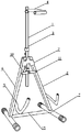
- a portable support frame for a musical instrument including a support device 1 and a support device 2 for a handle part of the musical instrument, the support device and the support device 2 are movably connected,
- the support device 1 includes an adjustable lever with an adjustable length and a placement part 1 for placing a handle portion of the musical instrument.
- the support device 2 includes an I-shaped support chassis, a movable adjustment bracket and a center connector disposed above the support chassis,
- the adjusting rod on the supporting device one is inserted above the supporting device through a central connecting piece, the bottom of the adjusting rod extends out of the central connecting piece, the side of the adjusting rod is provided with a fixed knob, and the central connecting piece It is hinged with the upper part of the movable adjustment frame, and two sides of the movable adjustment frame are provided with a placing part two for preventing the bottom of the musical instrument, and a movable card one and a movable card two are arranged in the middle of the movable adjustment frame.
- Hinged on movable card one and movable card two respectively, hinged between the movable card one and the movable card two, when the support frame is opened, the movable card one and the movable card two are on the same straight line in the horizontal direction, when the support frame is folded up At this time, the movable card one and the movable card two are on the same straight line in the vertical direction.
- both the placement part 1 and the placement part 2 are arranged in an arc-shaped structure, the outer surface is coated with a layer of soft silica gel, the placement part 1 is arranged in a horizontal direction, and the opening of the placement part 2 faces upward.
- the adjustment rod includes a rod one and a rod two, the rod one is inserted inside the rod two, and the rod one and the rod two are provided with a fixing member for fixing the rod two at the connecting portion.
- the placing part one is fixedly connected with the adjusting rod
- the placing part two is fixedly connected with the movable adjusting frame.
- the movable adjusting frame is arranged in an inverted V-shaped structure, and the I-shaped supporting base frame includes cross bars on both sides and a center bar disposed between the cross bars. Inter-thread connection, the movable adjustment frame and the cross-bar of the I-shaped support base frame are connected by welding, and the two ends of the cross-bar are provided with threaded silicone sleeves.
- the center rod is a center rod with adjustable length, including a first connecting rod and a second connecting rod, and the first connecting rod and the second connecting rod are connected by a screw thread.
- the invention has the advantages that the portable support frame for musical instruments of the present invention effectively solves the problems in the prior art, and has the advantages of small space occupation and low transportation cost; the bottom of the present invention is unique
- the I-shaped structure setting increases the overall stability of the support frame.
- the two ends of the cross bar are provided with threaded silicone sleeves, which increases the friction with the ground and makes the temperature more.
- the adjustment rod on the support device can be based on Need to adjust the overall height, flexible and convenient; hinged between the movable adjustment frame and the central connector, easy to fold and retract, saving space, easy to carry and transport; placement part 1 and placement part 2 are set in a circular arc-shaped structure
- the outer surface is covered with a layer of soft silica gel, which reduces the friction between the support frame and the musical instrument; the production cost of the invention is economical and reasonable, and the performance is excellent, which is suitable for promotion and use in the society.
- FIG. 1 is a schematic structural view of a portable support frame for musical instruments of the present invention
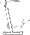
- FIG. 2 is a schematic view of the stowed structure of a portable support frame for musical instruments of the present invention
- FIG. 3 is a schematic structural view of the present invention with the center rod removed;
- FIG. 4 is a schematic diagram of the cross-sectional structure of the center rod.
- a portable support frame for a musical instrument which includes a support device 1 1 and a support device 2 2 for a handle portion of the musical instrument.
- the support device 1 is movably connected to the support device 2 2.
- the supporting device one 1 includes an adjustable rod 3 with an adjustable length and a placing part one 4 for placing the handle portion of the musical instrument.
- the supporting device two 2 includes an I-shaped supporting base 5 and a movable adjusting frame 6 provided above the supporting base 5 And the central connecting member 7, the adjusting rod 3 on the supporting device one 1 is inserted above the supporting device two 2 through the central connecting member 7, the bottom of the adjusting rod 3 extends out of the central connecting member 7, the adjusting rod 3 is provided with a fixed knob 8 on the side, and the central connecting member 7 is hinged with the upper part of the movable adjustment frame 6, and the two sides of the movable adjustment frame 6 are each provided with a placement part 2 for preventing the bottom of the musical instrument, the movable adjustment A movable card 10 and a movable card 11 are provided in the middle of the rack 6, and the movable adjusting frame 6 is hinged between the movable card 10 and the movable card 11 respectively, and the movable card 10 and the movable card 21 are hinged, When the support frame is opened, the movable card one 10 and the movable card two 11 are on the same straight line in the horizontal direction,
- the placing part one 4 and the placing part two 9 are both arranged in an arc-shaped structure, the outer surface is coated with a layer of soft silica gel, the placing part one 4 is arranged in a horizontal direction, and the opening of the placing part two 9 faces upward.
- the adjusting rod 3 includes a rod one 12 and a rod two 13.
- the rod one 12 is inserted inside the rod two 13.
- the rod one 12 and the rod two 13 are provided with fixing parts for fixing the rod two 13 at the connecting portion 14.
- the placing part one 4 is fixedly connected with the adjusting rod 3, and the placing part two 9 is fixedly connected with the movable adjusting frame 6.
- the movable adjusting frame 6 is arranged in an inverted V-shaped structure.
- the I-shaped supporting chassis 5 includes lateral bars 15 on both sides and a central bar 16 disposed between the lateral bars.
- the central bar 16 and the horizontal bar The rods 15 are threadedly connected, and the movable adjusting frame 6 is connected to the horizontal bar 15 of the I-shaped supporting base frame 5 by welding. Both ends of the horizontal bar 15 are provided with threaded silicone sleeves 18.
- the center rod 6 is a center rod with adjustable length, and includes a first connecting rod 16 and a second connecting rod 17, and the first connecting rod 16 and the second connecting rod 7 are connected by a screw thread.
- the specific implementation process of a portable support frame for musical instruments of the present invention is as follows: When the present invention is used, the height of the adjustment rod 3 is adjusted according to the size of the musical instrument, and after adjustment, it is fixed with a fixing member 14, which is flexible and convenient.
- the handle part is placed in the placement part 1 and the bottom part is placed in the placement part 2 and 9; the bottom of the I-shaped chassis 5 supports more stable, the center of the center rod 16 is screwed, and can be adjusted according to the end of the rotating center rod 16
- the crossbars 15 at both ends of the I-shaped chassis 5 are supported. Silicone sleeves 18 are provided at both ends of the crossbar 15 to increase the friction between the crossbar 14 and the ground, which plays a role of stable support.
Landscapes
- Physics & Mathematics (AREA)
- Engineering & Computer Science (AREA)
- Acoustics & Sound (AREA)
- Multimedia (AREA)
- Auxiliary Devices For Music (AREA)
- Electrophonic Musical Instruments (AREA)
Abstract
Disclosed is a portable support frame for a musical instrument. The support frame comprises a supporting device I (1) for a handle portion of a musical instrument, and a supporting device II (2). The supporting device I (1) is movably connected to the supporting device II (2). The supporting device I (1) comprises an adjusting rod (3) with an adjustable length and a placing portion I (4) for placement of the handle portion of the musical instrument. The supporting device II (2) comprises an I-shaped supporting chassis (5), a movable adjusting frame (6) arranged above the supporting chassis (5), and a central connecting member (7). The adjusting rod (3) of the supporting device I (1) is arranged above the supporting device II (2) by means of the central connecting member (7) in an inserted manner, the bottom portion of the adjusting rod (3) extends out of the central connecting member (7), and a fixed rotary knob (8) is provided on a side face of the adjusting rod (3). The central connecting member (7) is hinged to an upper portion of the movable adjusting frame (6), placing portions II (9) for placement of the bottom portion of the musical instrument are respectively provided on two sides of the movable adjusting frame (6), and a movable clamp I (10) and a movable clamp II (11) are provided in the middle of the movable adjusting frame (6). The portable support frame uses a unique structural design, has a good supporting performance, and is convenient to fold, therefore saving on occupied space, being convenient to transport, being manufactured economically and rationally, and being suitable for popularization and application in society.
Description
本发明涉及一种支撑架,具体是指一种用于乐器的便携式支撑架。The invention relates to a support frame, in particular to a portable support frame for musical instruments.
现有乐器支架由立杆和支撑立杆的脚架组成,脚架由脚套和支腿组成,现有技术的脚架支腿焊接在立杆上,不能拆卸,存储占用空间大,运输成本高,且不能针对不同型号的乐器进行调整,市面上的放置吉他、尤克里里等乐器支架靠电焊焊接等硬组合方式组合、体积大携带不方便;而可折叠类塑胶乐器支架存在强度不够容易出现变型问题;传统乐器支架的承托乐器的托架是靠电焊进行一端焊接的,承托力不足且焊接繁琐不环保。所以,一种性能优良,用于乐器的便携式支撑架成为整个社会亟待解决的问题。The existing musical instrument support is composed of a vertical pole and a tripod supporting the vertical pole. The tripod is composed of a foot cover and a leg. The prior art tripod legs are welded to the vertical pole and cannot be disassembled. The storage space is large and the transportation cost It is high and can not be adjusted for different types of musical instruments. The instrument brackets for placing guitars, ukuleles and other musical instruments on the market are combined by hard combination methods such as welding and welding. The problem of deformation is easy to occur; the bracket of the traditional musical instrument bracket supporting the musical instrument is welded at one end by electric welding, the supporting force is insufficient and the welding is cumbersome and not environmentally friendly. Therefore, a portable supporting frame for musical instruments with excellent performance has become an urgent problem to be solved in the whole society.
发明内容Summary of the invention
本发明要解决的技术问题是现有技术中的支撑架不能拆卸、运输成本大,占用空间等问题。The technical problem to be solved by the present invention is that the support frame in the prior art cannot be disassembled, the transportation cost is large, and the space is occupied.
为解决上述技术问题,本发明提供的技术方案为:一种用于乐器的便携式支撑架,包括用于乐器手柄部的支撑装置一和支撑装置二,所述支撑装置与支撑装置二活动连接,所述支撑装置一包括可调节长度的调节杆和放置乐器手柄部的放置部一,所述支撑装置二包括工字型支撑底架,设置在支撑底架上方的活动调节架和中心连接件,所述支撑装置一上的调节杆通过中心连接件插接在支撑装置二的上方,所述调节杆的底部伸出中心连接件,所述调节杆的侧面设有固定旋钮,所述中心连接件与活动调节架的上方铰接,所述活动调节架的两侧各设有用于防止乐器底部的放置部二,所述活动调节架的中间设有活动卡一和活动卡二,所述活动调节架分别于活动卡一和活动卡二铰接,所述活动卡一和活动卡二之间铰接,当支撑架打开时,活动卡一和活动卡二在水平方向处于同一直线上,当支撑架折叠起时,活动卡一和活动卡二在竖直方向处于同一直线上。In order to solve the above technical problems, the technical solution provided by the present invention is: a portable support frame for a musical instrument, including a support device 1 and a support device 2 for a handle part of the musical instrument, the support device and the support device 2 are movably connected, The support device 1 includes an adjustable lever with an adjustable length and a placement part 1 for placing a handle portion of the musical instrument. The support device 2 includes an I-shaped support chassis, a movable adjustment bracket and a center connector disposed above the support chassis, The adjusting rod on the supporting device one is inserted above the supporting device through a central connecting piece, the bottom of the adjusting rod extends out of the central connecting piece, the side of the adjusting rod is provided with a fixed knob, and the central connecting piece It is hinged with the upper part of the movable adjustment frame, and two sides of the movable adjustment frame are provided with a placing part two for preventing the bottom of the musical instrument, and a movable card one and a movable card two are arranged in the middle of the movable adjustment frame. Hinged on movable card one and movable card two respectively, hinged between the movable card one and the movable card two, when the support frame is opened, the movable card one and the movable card two are on the same straight line in the horizontal direction, when the support frame is folded up At this time, the movable card one and the movable card two are on the same straight line in the vertical direction.
进一步地,所述放置部一和放置部二均呈圆弧状结构设置,外表面包裹一层软质硅胶,所述放置部一呈水平方向设置,所述放置部二的开口朝上。Further, both the placement part 1 and the placement part 2 are arranged in an arc-shaped structure, the outer surface is coated with a layer of soft silica gel, the placement part 1 is arranged in a horizontal direction, and the opening of the placement part 2 faces upward.
进一步地,所述调节杆包括杆一和杆二,所述杆一插接在杆二的内部,所述杆一和杆二在连接部设有用于固定杆二的固定件。Further, the adjustment rod includes a rod one and a rod two, the rod one is inserted inside the rod two, and the rod one and the rod two are provided with a fixing member for fixing the rod two at the connecting portion.
进一步地,所述放置部一与调节杆之间固定连接,所述放置部二与活动调节架之间固定连接。Further, the placing part one is fixedly connected with the adjusting rod, and the placing part two is fixedly connected with the movable adjusting frame.
进一步地,所述活动调节架呈倒立的V字型结构设置,所述工字型支撑底架包括两侧的横杆和设置在横杆之间的中心杆,所述中心杆与横杆之间螺纹连接,所述活动调节架与工字型支撑底架的横杆之间通过焊接连接,所述横杆的两端设有带有螺纹的硅胶套。Further, the movable adjusting frame is arranged in an inverted V-shaped structure, and the I-shaped supporting base frame includes cross bars on both sides and a center bar disposed between the cross bars. Inter-thread connection, the movable adjustment frame and the cross-bar of the I-shaped support base frame are connected by welding, and the two ends of the cross-bar are provided with threaded silicone sleeves.
进一步地,所述中心杆为可调节长短的中心杆,包括第一连接杆和第二连接杆,所述第一连接杆和第二连接杆之间通过螺纹连接。Further, the center rod is a center rod with adjustable length, including a first connecting rod and a second connecting rod, and the first connecting rod and the second connecting rod are connected by a screw thread.
发明与现有技术相比的优点在于:本发明一种用于乐器的便携式支撑架有效地解决了现有技术中存在的问题,具有占用空间小,运输成本低等优点;本发明底部采用独特的工字型结构设置,增加了支撑架整体的稳定度,横杆的两端设有带有螺纹的硅胶套,增加了与地面的摩擦力,更加温度;支撑装置一上的调节杆可以根据需要调节整体的高度,灵活方便;活动调节架与中心连接件之间铰接,方便折叠和收起,节约了占用空间,方便携带和运输;放置部一和放置部二均呈圆弧状结构设置,外表面包裹一层软质硅胶,减小了支撑架与乐器之间的摩擦;本发明的制作成本经济合理,性能优良,适宜在社会上推广使用。Compared with the prior art, the invention has the advantages that the portable support frame for musical instruments of the present invention effectively solves the problems in the prior art, and has the advantages of small space occupation and low transportation cost; the bottom of the present invention is unique The I-shaped structure setting increases the overall stability of the support frame. The two ends of the cross bar are provided with threaded silicone sleeves, which increases the friction with the ground and makes the temperature more. The adjustment rod on the support device can be based on Need to adjust the overall height, flexible and convenient; hinged between the movable adjustment frame and the central connector, easy to fold and retract, saving space, easy to carry and transport; placement part 1 and placement part 2 are set in a circular arc-shaped structure The outer surface is covered with a layer of soft silica gel, which reduces the friction between the support frame and the musical instrument; the production cost of the invention is economical and reasonable, and the performance is excellent, which is suitable for promotion and use in the society.
图1是本发明一种用于乐器的便携式支撑架的结构示意图;1 is a schematic structural view of a portable support frame for musical instruments of the present invention;
图2是本发明一种用于乐器的便携式支撑架的收起结构示意图;2 is a schematic view of the stowed structure of a portable support frame for musical instruments of the present invention;
图3是本发明将中心杆去除的结构示意图;3 is a schematic structural view of the present invention with the center rod removed;
图4是中心杆的剖面结构示意图。4 is a schematic diagram of the cross-sectional structure of the center rod.
如图所示:1、支撑装置一,2、支撑装置二,3、调节杆,4、放置部一,5、工字型支撑底架,6、活动调节架,7、中心连接件,8、固定旋钮,9、放置部二,10、活动卡一,11、活动卡二,12、杆一,13、杆二,14、固定件,15、横杆,16、第一连接杆,17、第二连接杆。As shown in the figure: 1, support device 1, 2, support device 2, 3, adjustment rod, 4, placement part 1, 5, I-shaped support chassis, 6, movable adjustment frame, 7, center connector, 8 , Fixed knob, 9, placement part two, 10, movable card one, 11, movable card two, 12, rod one, 13, rod two, 14, fixing parts, 15, cross bar, 16, first connecting rod, 17 2. The second connecting rod.
下面结合附图对本发明做进一步的详细说明。The present invention will be further described in detail below with reference to the drawings.
结合附图1-4,对本发明进行详细介绍。The present invention will be described in detail with reference to FIGS. 1-4.
本发明在具体实施时提供了一种用于乐器的便携式支撑架,包括用于乐器手柄部的支撑装置一1和支撑装置二2,所述支撑装置1与支撑装置二2活动连接,所述支撑装置一1包括可调节长度的调节杆3和放置乐器手柄部的放置部一4,所述支撑装置二2包括工字型支撑底架5,设置在支撑底架5上方的活动调节架6和中心连接件7,所述支撑装置一1上的调节杆3通过中心连接件7插接在支撑装置二2的上方,所述调节杆3的底部伸出中心连接件7,所述调节杆3的侧面设有固定旋钮8,所述中心连接件7与活动调节架6的上方铰接,所述活动调节架6的两侧各设有用于防止乐器底部的放置部二9,所述活动调节架6的中间设有活动卡一10和活动卡二11,所述活动调节架6分别于活动卡一10和活动卡二11铰接,所述活动卡一10和活动卡二11之间铰接,当支撑架打开时,活动卡一10和活动卡二11在水平方向处于同一直线上,当支撑架折叠起时,活动卡一10和活动卡二11在竖直方向处于同一直线上。In the specific implementation of the present invention, a portable support frame for a musical instrument is provided, which includes a support device 1 1 and a support device 2 2 for a handle portion of the musical instrument. The support device 1 is movably connected to the support device 2 2. The supporting device one 1 includes an adjustable rod 3 with an adjustable length and a placing part one 4 for placing the handle portion of the musical instrument. The supporting device two 2 includes an I-shaped supporting base 5 and a movable adjusting frame 6 provided above the supporting base 5 And the central connecting member 7, the adjusting rod 3 on the supporting device one 1 is inserted above the supporting device two 2 through the central connecting member 7, the bottom of the adjusting rod 3 extends out of the central connecting member 7, the adjusting rod 3 is provided with a fixed knob 8 on the side, and the central connecting member 7 is hinged with the upper part of the movable adjustment frame 6, and the two sides of the movable adjustment frame 6 are each provided with a placement part 2 for preventing the bottom of the musical instrument, the movable adjustment A movable card 10 and a movable card 11 are provided in the middle of the rack 6, and the movable adjusting frame 6 is hinged between the movable card 10 and the movable card 11 respectively, and the movable card 10 and the movable card 21 are hinged, When the support frame is opened, the movable card one 10 and the movable card two 11 are on the same straight line in the horizontal direction, and when the support frame is folded, the movable card one 10 and the movable card two 11 are on the same straight line in the vertical direction.
所述放置部一4和放置部二9均呈圆弧状结构设置,外表面包裹一层软质硅胶,所述放置部一4呈水平方向设置,所述放置部二9的开口朝上。所述调节杆3包括杆一12和杆二13,所述杆一12插接在杆二13的内部,所述杆一12和杆二13在连接部设有用于固定杆二13的固定件14。所述放置部一4与调节杆3之间固定连接,所述放置部二9与活动调节架6之间固定连接。所述活动调节架6呈倒立的V字型结构设置,所述工字型支撑底架5包括两侧的横杆15和设置在横杆之间的中心杆16,所述中心杆16与横杆 15之间螺纹连接,所述活动调节架6与工字型支撑底架5的横杆15之间通过焊接连接,所述横杆15的两端设有带有螺纹的硅胶套18。所述中心杆6为可调节长短的中心杆,包括第一连接杆16和第二连接杆17,所述第一连接杆16和第二连接杆7之间通过螺纹连接。The placing part one 4 and the placing part two 9 are both arranged in an arc-shaped structure, the outer surface is coated with a layer of soft silica gel, the placing part one 4 is arranged in a horizontal direction, and the opening of the placing part two 9 faces upward. The adjusting rod 3 includes a rod one 12 and a rod two 13. The rod one 12 is inserted inside the rod two 13. The rod one 12 and the rod two 13 are provided with fixing parts for fixing the rod two 13 at the connecting portion 14. The placing part one 4 is fixedly connected with the adjusting rod 3, and the placing part two 9 is fixedly connected with the movable adjusting frame 6. The movable adjusting frame 6 is arranged in an inverted V-shaped structure. The I-shaped supporting chassis 5 includes lateral bars 15 on both sides and a central bar 16 disposed between the lateral bars. The central bar 16 and the horizontal bar The rods 15 are threadedly connected, and the movable adjusting frame 6 is connected to the horizontal bar 15 of the I-shaped supporting base frame 5 by welding. Both ends of the horizontal bar 15 are provided with threaded silicone sleeves 18. The center rod 6 is a center rod with adjustable length, and includes a first connecting rod 16 and a second connecting rod 17, and the first connecting rod 16 and the second connecting rod 7 are connected by a screw thread.
本发明一种用于乐器的便携式支撑架的具体实施过程如下:本发明在使用时,根据乐器的大小调节调节杆3的高度,调节完毕后,用固定件14固定,灵活方便,将乐器的手柄部放置在放置部一4处,底部放置在放置部二9处;底部的工字型底架5支撑更加稳定,中心杆16的中心采用螺纹连接,可以根据旋转中心杆16的一端,调节至需要的长度,支撑工字型底架5两端的横杆15,横杆15的两端设有硅胶套18,增加了横杆14与地面之间的摩擦,起到了稳定支撑的作用,当收起时,调节固定件14,放下调节杆3,旋转中心杆16,取出中心杆16,将V字型活动调节架6合并收起,占用空间小,方便运输,本发明的实用性较强,性能优良,适宜在社会上推广使用。The specific implementation process of a portable support frame for musical instruments of the present invention is as follows: When the present invention is used, the height of the adjustment rod 3 is adjusted according to the size of the musical instrument, and after adjustment, it is fixed with a fixing member 14, which is flexible and convenient. The handle part is placed in the placement part 1 and the bottom part is placed in the placement part 2 and 9; the bottom of the I-shaped chassis 5 supports more stable, the center of the center rod 16 is screwed, and can be adjusted according to the end of the rotating center rod 16 To the required length, the crossbars 15 at both ends of the I-shaped chassis 5 are supported. Silicone sleeves 18 are provided at both ends of the crossbar 15 to increase the friction between the crossbar 14 and the ground, which plays a role of stable support. When stowed, adjust the fixing member 14, lower the adjustment rod 3, rotate the center rod 16, take out the center rod 16, and put together the V-shaped movable adjustment frame 6, which takes up little space and is convenient for transportation. The invention has strong practicability , Excellent performance, suitable for promotion and use in the society.
以上对本发明及其实施方式进行了描述,这种描述没有限制性,附图中所示的也只是本发明的实施方式之一,实际的结构并不局限于此。总而言之如果本领域的普通技术人员受其启示,在不脱离本发明创造宗旨的情况下,不经创造性的设计出与该技术方案相似的结构方式及实施例,均应属于本发明的保护范围。The present invention and its embodiments have been described above. This description is not limiting, and the drawings shown are only one of the embodiments of the present invention, and the actual structure is not limited thereto. To sum up, if a person of ordinary skill in the art is inspired by it, without departing from the purpose of the invention, a structural method and an embodiment similar to the technical solution without creative design shall fall within the protection scope of the invention.
Claims (6)
- 一种用于乐器的便携式支撑架,其特征在于:包括用于乐器手柄部的支撑装置一(1)和支撑装置二(2),所述支撑装置(1)与支撑装置二(2)活动连接,所述支撑装置一(1)包括可调节长度的调节杆(3)和放置乐器手柄部的放置部一(4),所述支撑装置二(2)包括工字型支撑底架(5),设置在支撑底架(5)上方的活动调节架(6)和中心连接件(7),所述支撑装置一(1)上的调节杆(3)通过中心连接件(7)插接在支撑装置二(2)的上方,所述调节杆(3)的底部伸出中心连接件(7),所述调节杆(3)的侧面设有固定旋钮(8),所述中心连接件(7)与活动调节架(6)的上方铰接,所述活动调节架(6)的两侧各设有用于防止乐器底部的放置部二(9),所述活动调节架(6)的中间设有活动卡一(10)和活动卡二(11),所述活动调节架(6)分别于活动卡一(10)和活动卡二(11)铰接,所述活动卡一(10)和活动卡二(11)之间铰接,当支撑架打开时,活动卡一(10)和活动卡二(11)在水平方向处于同一直线上,当支撑架折叠起时,活动卡一(10)和活动卡二(11)在竖直方向处于同一直线上。A portable supporting frame for musical instruments, characterized in that it includes a supporting device one (1) and a supporting device two (2) for the handle part of the musical instrument, the supporting device (1) and the supporting device two (2) are movable Connected, the support device one (1) includes an adjustable length adjustment rod (3) and a placement part one (4) for placing the handle part of the instrument, and the support device two (2) includes an I-shaped support chassis (5 ), a movable adjusting frame (6) and a central connecting piece (7) provided above the supporting chassis (5), the adjusting rod (3) on the supporting device one (1) is inserted through the central connecting piece (7) Above the supporting device two (2), the bottom of the adjusting rod (3) protrudes from the central connecting piece (7), and the side of the adjusting rod (3) is provided with a fixed knob (8), the central connecting piece (7) Articulated with the upper part of the movable adjusting frame (6), two sides of the movable adjusting frame (6) are each provided with a placing part two (9) for preventing the bottom of the musical instrument, the middle of the movable adjusting frame (6) There are movable card one (10) and movable card two (11), the movable adjusting frame (6) is hinged to movable card one (10) and movable card two (11) respectively, and the movable card one (10) and The movable card two (11) is hinged. When the support frame is opened, the movable card one (10) and the movable card two (11) are on the same straight line in the horizontal direction. When the support frame is folded up, the movable card one (10) It is on the same straight line as the movable card two (11) in the vertical direction.
- 根据权利要求1所述的一种用于乐器的便携式支撑架,其特征在于:所述放置部一(4)和放置部二(9)均呈圆弧状结构设置,外表面包裹一层软质硅胶,所述放置部一(4)呈水平方向设置,所述放置部二(9)的开口朝上。The portable support frame for musical instruments according to claim 1, characterized in that: the placing part one (4) and the placing part two (9) are both arranged in an arc-shaped structure, and the outer surface is covered with a layer of soft For quality silica gel, the placement part one (4) is arranged in a horizontal direction, and the opening of the placement part two (9) faces upward.
- 根据权利要求1所述的一种用于乐器的便携式支撑架,其特征在于:所述调节杆(3)包括杆一(12)和杆二(13),所述杆一(12)插接在杆二(13)的内部,所述杆一(12)和杆二(13)在连接部设有用于固定杆二(13)的固定件(14)。The portable support frame for musical instruments according to claim 1, characterized in that: the adjusting rod (3) includes a rod one (12) and a rod two (13), the rod one (12) is plugged in Inside the rod two (13), the rod one (12) and the rod two (13) are provided with a fixing member (14) for fixing the rod two (13) at the connecting portion.
- 根据权利要求2所述的一种用于乐器的便携式支撑架,其特征在于:所述放置部一(4)与调节杆(3)之间固定连接,所述放置部二(9)与活动调节架(6)之间固定连接。The portable support frame for musical instruments according to claim 2, characterized in that: the placement part one (4) is fixedly connected with the adjusting rod (3), and the placement part two (9) is connected with the movable The fixed frame (6) is fixedly connected.
- 根据权利要求4所述的一种用于乐器的便携式支撑架,其特征在于:所述活动调节架(6)呈倒立的V字型结构设置,所述工字型支撑底架(5)包括两侧的横杆(15)和设置在横杆之间的中心杆(16),所述中心杆(16)与横杆(15)之间螺纹连接,所述活动调节架(6)与工字型支撑底架(5)的横杆(15)之间通过焊接连接,所述横杆(15)的两端设有带有螺纹的硅胶套(18)。The portable supporting frame for musical instruments according to claim 4, characterized in that: the movable adjusting frame (6) is arranged in an inverted V-shaped structure, and the I-shaped supporting frame (5) includes Cross bars (15) on both sides and a center bar (16) arranged between the cross bars, the center bar (16) and the cross bar (15) are threadedly connected, the movable adjusting frame (6) and the work The cross bars (15) of the font-shaped supporting chassis (5) are connected by welding, and the two ends of the cross bars (15) are provided with threaded silicone sleeves (18).
- 根据权利要求6所述的一种用于乐器的便携式支撑架,其特征在于:所述中心杆(6)为可调节长短的中心杆,包括第一连接杆(16)和第二连接杆(17),所述第一连接杆(16)和第二连接杆(7)之间通过螺纹连接。The portable support frame for musical instruments according to claim 6, characterized in that the center rod (6) is an adjustable length center rod, including a first connecting rod (16) and a second connecting rod (16) 17), the first connecting rod (16) and the second connecting rod (7) are connected by a screw thread.
Applications Claiming Priority (2)
| Application Number | Priority Date | Filing Date | Title |
|---|---|---|---|
| CN201811490694.6A CN109243412B (en) | 2018-12-07 | 2018-12-07 | Portable support frame for musical instrument |
| CN201811490694.6 | 2018-12-07 |
Publications (1)
| Publication Number | Publication Date |
|---|---|
| WO2020113628A1 true WO2020113628A1 (en) | 2020-06-11 |
Family
ID=65073906
Family Applications (1)
| Application Number | Title | Priority Date | Filing Date |
|---|---|---|---|
| PCT/CN2018/120465 WO2020113628A1 (en) | 2018-12-07 | 2018-12-12 | Portable support frame for musical instrument |
Country Status (2)
| Country | Link |
|---|---|
| CN (1) | CN109243412B (en) |
| WO (1) | WO2020113628A1 (en) |
Families Citing this family (1)
| Publication number | Priority date | Publication date | Assignee | Title |
|---|---|---|---|---|
| CN112071289B (en) * | 2020-09-16 | 2024-07-23 | 李沐良 | Foldable musical instrument stand and multi-head musical instrument stand |
Citations (6)
| Publication number | Priority date | Publication date | Assignee | Title |
|---|---|---|---|---|
| CN1471076A (en) * | 2002-07-24 | 2004-01-28 | ��˹-�˵á��������� | Support for musical instrument |
| EP1067509B1 (en) * | 1999-07-07 | 2005-03-16 | Yamaha Corporation | Compact stand for musical instrument |
| US20150194139A1 (en) * | 2014-01-07 | 2015-07-09 | Tsung-Yao Yu | Musical Instrument Stand that is Folded Easily |
| CN204516336U (en) * | 2015-04-02 | 2015-07-29 | 滨州职业学院 | A kind of musical instrument support |
| CN106098035A (en) * | 2016-06-03 | 2016-11-09 | 新昌县儒岙晨辉不锈钢制品厂 | A kind of adjustable rustless steel musical instrument stand |
| CN208061659U (en) * | 2018-04-05 | 2018-11-06 | 音王电声股份有限公司 | A kind of foldable guitar holder |
Family Cites Families (4)
| Publication number | Priority date | Publication date | Assignee | Title |
|---|---|---|---|---|
| US6484977B1 (en) * | 2001-08-17 | 2002-11-26 | Ming-Ti Yu | Musical instrument stand |
| DE20306127U1 (en) * | 2003-04-17 | 2003-11-20 | Ando, Akira, 10829 Berlin | Multifunctional device for a double bass and a double bass player |
| CN203102843U (en) * | 2012-02-21 | 2013-07-31 | 北京克强科技文化中心 | Portable electronic music score instrument |
| CN209543915U (en) * | 2018-12-07 | 2019-10-25 | 江苏沃格瑞特乐器制造有限公司 | A kind of portable support stand for musical instrument |
-
2018
- 2018-12-07 CN CN201811490694.6A patent/CN109243412B/en active Active
- 2018-12-12 WO PCT/CN2018/120465 patent/WO2020113628A1/en active Application Filing
Patent Citations (6)
| Publication number | Priority date | Publication date | Assignee | Title |
|---|---|---|---|---|
| EP1067509B1 (en) * | 1999-07-07 | 2005-03-16 | Yamaha Corporation | Compact stand for musical instrument |
| CN1471076A (en) * | 2002-07-24 | 2004-01-28 | ��˹-�˵á��������� | Support for musical instrument |
| US20150194139A1 (en) * | 2014-01-07 | 2015-07-09 | Tsung-Yao Yu | Musical Instrument Stand that is Folded Easily |
| CN204516336U (en) * | 2015-04-02 | 2015-07-29 | 滨州职业学院 | A kind of musical instrument support |
| CN106098035A (en) * | 2016-06-03 | 2016-11-09 | 新昌县儒岙晨辉不锈钢制品厂 | A kind of adjustable rustless steel musical instrument stand |
| CN208061659U (en) * | 2018-04-05 | 2018-11-06 | 音王电声股份有限公司 | A kind of foldable guitar holder |
Also Published As
| Publication number | Publication date |
|---|---|
| CN109243412A (en) | 2019-01-18 |
| CN109243412B (en) | 2024-01-16 |
Similar Documents
| Publication | Publication Date | Title |
|---|---|---|
| CN209185903U (en) | Multi-functional deformation fine arts drawing board bracket | |
| CN210248972U (en) | Portable multi-functional art easel | |
| WO2020113628A1 (en) | Portable support frame for musical instrument | |
| CN201327707Y (en) | Coillayer portable music stand | |
| CN205388902U (en) | Musical instrument rack | |
| CN106732852A (en) | Middle school student's chemical test test tube rack | |
| US2901860A (en) | Music rack and instrument support | |
| CN110619861B (en) | Portable electronic organ support | |
| CN207830918U (en) | A kind of adjustable metering box bracket | |
| CN205487313U (en) | Novel music stand is used in vocal music training | |
| CN206388498U (en) | A kind of Multi-functional music stand for Piano Teaching | |
| CN202774907U (en) | Folding table | |
| CN202774904U (en) | Foldable desk | |
| CN202660176U (en) | Multifunctional reading rack | |
| CN209543915U (en) | A kind of portable support stand for musical instrument | |
| CN208153992U (en) | A kind of display multiple degrees of freedom emergency support | |
| CN209365749U (en) | A kind of novel teaching aid for art teaching | |
| CN102247068A (en) | Retractable dressing mirror | |
| CN208697405U (en) | A kind of rack for artificial slabstone | |
| CN207779878U (en) | A kind of field spectroradiometer pipette tips support device | |
| CN210325178U (en) | Musical instrument auxiliary assembly | |
| CN206128593U (en) | Novel split heads scaffold puts up workstation | |
| CN211181206U (en) | Breath exercise device for vocal music training | |
| CN207833901U (en) | A kind of portable zither shelf | |
| CN219333118U (en) | Skating aid |
Legal Events
| Date | Code | Title | Description |
|---|---|---|---|
| 121 | Ep: the epo has been informed by wipo that ep was designated in this application |
Ref document number: 18942591 Country of ref document: EP Kind code of ref document: A1 |
|
| NENP | Non-entry into the national phase |
Ref country code: DE |
|
| 122 | Ep: pct application non-entry in european phase |
Ref document number: 18942591 Country of ref document: EP Kind code of ref document: A1 |