WO2020111259A1 - 平版印刷版原版、平版印刷版の作製方法、及び、平版印刷方法 - Google Patents
平版印刷版原版、平版印刷版の作製方法、及び、平版印刷方法 Download PDFInfo
- Publication number
- WO2020111259A1 WO2020111259A1 PCT/JP2019/046871 JP2019046871W WO2020111259A1 WO 2020111259 A1 WO2020111259 A1 WO 2020111259A1 JP 2019046871 W JP2019046871 W JP 2019046871W WO 2020111259 A1 WO2020111259 A1 WO 2020111259A1
- Authority
- WO
- WIPO (PCT)
- Prior art keywords
- group
- printing plate
- lithographic printing
- compound
- plate precursor
- Prior art date
- Legal status (The legal status is an assumption and is not a legal conclusion. Google has not performed a legal analysis and makes no representation as to the accuracy of the status listed.)
- Ceased
Links
Images






Classifications
-
- B—PERFORMING OPERATIONS; TRANSPORTING
- B41—PRINTING; LINING MACHINES; TYPEWRITERS; STAMPS
- B41C—PROCESSES FOR THE MANUFACTURE OR REPRODUCTION OF PRINTING SURFACES
- B41C1/00—Forme preparation
- B41C1/10—Forme preparation for lithographic printing; Master sheets for transferring a lithographic image to the forme
- B41C1/1008—Forme preparation for lithographic printing; Master sheets for transferring a lithographic image to the forme by removal or destruction of lithographic material on the lithographic support, e.g. by laser or spark ablation; by the use of materials rendered soluble or insoluble by heat exposure, e.g. by heat produced from a light to heat transforming system; by on-the-press exposure or on-the-press development, e.g. by the fountain of photolithographic materials
-
- B—PERFORMING OPERATIONS; TRANSPORTING
- B41—PRINTING; LINING MACHINES; TYPEWRITERS; STAMPS
- B41N—PRINTING PLATES OR FOILS; MATERIALS FOR SURFACES USED IN PRINTING MACHINES FOR PRINTING, INKING, DAMPING, OR THE LIKE; PREPARING SUCH SURFACES FOR USE AND CONSERVING THEM
- B41N1/00—Printing plates or foils; Materials therefor
- B41N1/12—Printing plates or foils; Materials therefor non-metallic other than stone, e.g. printing plates or foils comprising inorganic materials in an organic matrix
- B41N1/14—Lithographic printing foils
-
- G—PHYSICS
- G03—PHOTOGRAPHY; CINEMATOGRAPHY; ANALOGOUS TECHNIQUES USING WAVES OTHER THAN OPTICAL WAVES; ELECTROGRAPHY; HOLOGRAPHY
- G03F—PHOTOMECHANICAL PRODUCTION OF TEXTURED OR PATTERNED SURFACES, e.g. FOR PRINTING, FOR PROCESSING OF SEMICONDUCTOR DEVICES; MATERIALS THEREFOR; ORIGINALS THEREFOR; APPARATUS SPECIALLY ADAPTED THEREFOR
- G03F7/00—Photomechanical, e.g. photolithographic, production of textured or patterned surfaces, e.g. printing surfaces; Materials therefor, e.g. comprising photoresists; Apparatus specially adapted therefor
-
- G—PHYSICS
- G03—PHOTOGRAPHY; CINEMATOGRAPHY; ANALOGOUS TECHNIQUES USING WAVES OTHER THAN OPTICAL WAVES; ELECTROGRAPHY; HOLOGRAPHY
- G03F—PHOTOMECHANICAL PRODUCTION OF TEXTURED OR PATTERNED SURFACES, e.g. FOR PRINTING, FOR PROCESSING OF SEMICONDUCTOR DEVICES; MATERIALS THEREFOR; ORIGINALS THEREFOR; APPARATUS SPECIALLY ADAPTED THEREFOR
- G03F7/00—Photomechanical, e.g. photolithographic, production of textured or patterned surfaces, e.g. printing surfaces; Materials therefor, e.g. comprising photoresists; Apparatus specially adapted therefor
- G03F7/004—Photosensitive materials
-
- G—PHYSICS
- G03—PHOTOGRAPHY; CINEMATOGRAPHY; ANALOGOUS TECHNIQUES USING WAVES OTHER THAN OPTICAL WAVES; ELECTROGRAPHY; HOLOGRAPHY
- G03F—PHOTOMECHANICAL PRODUCTION OF TEXTURED OR PATTERNED SURFACES, e.g. FOR PRINTING, FOR PROCESSING OF SEMICONDUCTOR DEVICES; MATERIALS THEREFOR; ORIGINALS THEREFOR; APPARATUS SPECIALLY ADAPTED THEREFOR
- G03F7/00—Photomechanical, e.g. photolithographic, production of textured or patterned surfaces, e.g. printing surfaces; Materials therefor, e.g. comprising photoresists; Apparatus specially adapted therefor
- G03F7/004—Photosensitive materials
- G03F7/027—Non-macromolecular photopolymerisable compounds having carbon-to-carbon double bonds, e.g. ethylenic compounds
- G03F7/028—Non-macromolecular photopolymerisable compounds having carbon-to-carbon double bonds, e.g. ethylenic compounds with photosensitivity-increasing substances, e.g. photoinitiators
-
- G—PHYSICS
- G03—PHOTOGRAPHY; CINEMATOGRAPHY; ANALOGOUS TECHNIQUES USING WAVES OTHER THAN OPTICAL WAVES; ELECTROGRAPHY; HOLOGRAPHY
- G03F—PHOTOMECHANICAL PRODUCTION OF TEXTURED OR PATTERNED SURFACES, e.g. FOR PRINTING, FOR PROCESSING OF SEMICONDUCTOR DEVICES; MATERIALS THEREFOR; ORIGINALS THEREFOR; APPARATUS SPECIALLY ADAPTED THEREFOR
- G03F7/00—Photomechanical, e.g. photolithographic, production of textured or patterned surfaces, e.g. printing surfaces; Materials therefor, e.g. comprising photoresists; Apparatus specially adapted therefor
- G03F7/004—Photosensitive materials
- G03F7/09—Photosensitive materials characterised by structural details, e.g. supports, auxiliary layers
Definitions
- the present disclosure relates to a lithographic printing plate precursor, a method for producing a lithographic printing plate, and a lithographic printing method.
- a lithographic printing plate comprises a lipophilic image area that receives ink during the printing process and a hydrophilic non-image area that receives fountain solution.
- the lipophilic image part of the lithographic printing plate is used as the ink receiving part and the hydrophilic non-image part is dampening water receiving part (ink non-receiving part) by utilizing the property that water and oil-based ink repel each other.
- a difference in ink adhesion is caused on the surface of the lithographic printing plate, the ink is applied only to the image portion, and then the ink is transferred to a printing medium such as paper for printing.
- a lithographic printing plate precursor in which a lipophilic photosensitive resin layer (image recording layer) is provided on a hydrophilic support has been widely used.
- the lithographic printing plate precursor is exposed through an original image such as a lith film, and then a portion which becomes an image portion of the image recording layer is left, and the other unnecessary image recording layer is treated with an alkaline developer or an organic solvent.
- a lithographic printing plate is obtained by carrying out plate making by a method of dissolving and removing with a solvent and exposing the hydrophilic support surface to form a non-image area.
- Patent Document 1 discloses a support having a hydrophilic surface or a support provided with a hydrophilic layer and a coating provided on the support, which includes hydrophobic thermoplastic polymer particles, a binder and an infrared absorbing dye.
- a coating including an image recording layer; the hydrophobic thermoplastic polymer particles have an average particle diameter measured by photon correlation spectroscopy of 10 nm or more and less than 40 nm, and the amount of the IR dye does not consider any counter ion.
- 0.80 mg/m 2 of the total surface area of the thermoplastic polymer particles as determined by hydrodynamic fractionation, and the amount of the hydrophobic thermoplastic polymer particles based on the total weight of the components of the imaging layer is at least 60%.
- a heat-sensitive negative lithographic printing plate precursor is described.
- Patent Document 2 discloses a lithographic substrate; and a) a radical-polymerizable component; b) an initiator system capable of generating sufficient radicals to initiate a polymerization reaction when exposed to image-forming radiation; And c) a structural unit having a hydrophobic backbone and i) a pendant cyano group directly attached to the hydrophobic backbone, and ii) a pendant group comprising a hydrophilic poly(alkylene oxide) segment.
- An imageable element is described that comprises a polymeric binder that includes both of the constituent units having
- Patent Document 1 European Patent Application Publication No. 1,859,935
- Patent Document 2 Japanese Patent Publication No. 2008-503365
- planographic printing plate a planographic printing plate excellent in the number of printable plates (hereinafter, also referred to as “printing durability”) is required.
- an ink for printing an ink that is cured by irradiation with ultraviolet rays (UV) (also referred to as “ultraviolet curable ink or UV ink”) may be used.
- UV ink has high productivity because it can be dried instantly, generally has a low content of solvent, or it is easy to reduce environmental pollution because it is solvent-free. Do not dry with heat, or dry with heat. Since an image can be formed in a short time, it has an advantage that the range of applications such as printing targets is expanded.
- a lithographic printing plate precursor capable of providing a lithographic printing plate excellent in printing durability even when using a UV ink is considered to be very useful industrially.
- the present inventor found that the lithographic printing plate precursor described in Patent Document 1 or Patent Document 2 had insufficient printing durability, particularly when UV ink was used as the ink. I found that there is.
- the problem to be solved by one embodiment of the present disclosure is to provide a lithographic printing plate precursor having excellent printing durability even when UV ink is used in the obtained lithographic printing plate.
- a problem to be solved by another embodiment of the present disclosure is to provide a method for producing a planographic printing plate using the planographic printing plate precursor, or a planographic printing method.
- Means for solving the above problems include the following aspects.
- a lithographic printing plate precursor which has an image recording layer on a support, and the image recording layer contains an infrared absorber, a polymerization initiator, a polymerizable compound, and thermoplastic resin particles.
- thermoplastic resin contained in the thermoplastic resin particles contains a structural unit formed of an aromatic vinyl compound, and a resin A having a structural unit having a cyano group
- ⁇ 4> The lithographic printing plate precursor as described in any one of ⁇ 1> to ⁇ 3>, in which the thermoplastic resin contained in the thermoplastic resin particles has a hydrophilic group.
- thermoplastic resin contained in the thermoplastic resin particles has a polyalkylene oxide structure as the hydrophilic group.
- thermoplastic resin particles have an arithmetic average particle diameter of 1 nm or more and less than 80 nm.
- ⁇ 8> The lithographic printing plate precursor as described in any one of ⁇ 1> to ⁇ 7> above, wherein the polymerization initiator contains an electron-accepting polymerization initiator.
- the electron accepting polymerization initiator has a LUMO of ⁇ 3.0 eV or less.
- the difference between the LUMO of the electron-accepting polymerization initiator and the LUMO of the infrared absorber is 0.70 eV or less.
- ⁇ 11> The lithographic printing plate precursor as described in any one of ⁇ 1> to ⁇ 10>, in which the polymerization initiator further contains an electron donating polymerization initiator.
- ⁇ 12> The lithographic printing plate precursor as described in ⁇ 11>, in which the difference between the HOMO of the infrared absorber and the HOMO of the electron-donating polymerization initiator is 0.70 eV or less.
- ⁇ 13> The lithographic printing plate precursor as described in any one of ⁇ 1> to ⁇ 12>, wherein the infrared absorber is a cationic polymethine dye having an oxygen atom or a nitrogen atom at a meso position.
- ⁇ 14> The lithographic printing plate precursor as described in any one of ⁇ 1> to ⁇ 13>, wherein the infrared absorber is a decomposable infrared absorber that decomposes due to heat caused by infrared exposure and electron transfer. . ⁇ 15> The lithographic printing plate precursor as described in ⁇ 14>, wherein the decomposable infrared absorbent is an infrared absorbent represented by the following formula 1-1.
- R 1 represents a group represented by Formula 2 below, and R 11 to R 18 each independently represent a hydrogen atom, a halogen atom, —R a , —OR b , —SR c or —NR.
- R e , R a to R e each independently represents a hydrocarbon group, and A 1 , A 2 and a plurality of R 11 to R 18 may combine to form a monocyclic or polycyclic ring.
- a 1 and A 2 each independently represent an oxygen atom, a sulfur atom or a nitrogen atom
- n 11 and n 12 each independently represent an integer of 0 to 5, provided that the sum of n 11 and n 12 is 2 or more
- n 13 and n 14 each independently represent 0 or 1
- L represents an oxygen atom, a sulfur atom or —NR 10 —
- R 10 represents a hydrogen atom, an alkyl group or an aryl group
- Za represents a counter ion that neutralizes the charge.
- R Z represents an alkyl group
- the wavy line represents the bonding site with the group represented by L in Formula 1-1.
- ⁇ 16> The planographic printing plate according to any one of ⁇ 1> to ⁇ 15>, in which the content of the infrared absorbent is 0.1% by mass to 10% by mass based on the total mass of the image recording layer.
- ⁇ 17> The lithographic printing plate precursor as described in any one of ⁇ 1> to ⁇ 16>, wherein the polymerizable compound has an ethylenically unsaturated bond equivalent of 200 g/mol or less.
- ⁇ 18> The lithographic printing plate precursor as described in any one of ⁇ 1> to ⁇ 17>, wherein the polymerizable compound has a weight average molecular weight of 1,500 or less.
- ⁇ 19> The lithographic printing plate precursor as described in any one of ⁇ 1> to ⁇ 18>, wherein the polymerizable compound contains a trifunctional or higher functional polymerizable compound.
- ⁇ 20> The lithographic printing plate precursor as described in any one of ⁇ 1> to ⁇ 18>, in which the polymerizable compound has a 7-functional or higher-functional polymerizable group.
- ⁇ 21> The lithographic printing plate precursor as described in any one of ⁇ 1> to ⁇ 18>, in which the polymerizable compound has a 10- or more-functional polymerizable group.
- ⁇ 22> The lithographic printing plate precursor as described in any one of ⁇ 1> to ⁇ 21>, in which the image recording layer contains two or more polymerizable compounds.
- ⁇ 23> The lithographic printing plate precursor as described in any one of ⁇ 1> to ⁇ 22>, wherein the image recording layer further contains an acid color developing agent.
- ⁇ 24> The lithographic printing plate precursor as described in any one of ⁇ 1> to ⁇ 23>, wherein the image recording layer further contains a development accelerator.
- ⁇ 25> The lithographic printing plate precursor as described in any one of ⁇ 1> to ⁇ 24>, wherein the image recording layer further contains an oil sensitizer.
- the support has micropores on the image recording layer side surface, The lithographic printing plate precursor as described in any one of ⁇ 1> to ⁇ 25>, wherein the average diameter of the micropores on the surface is more than 13 nm and 100 nm or less.
- the support has an anodic oxide coating on the surface on the image recording layer side,
- the anodized film has the micropores extending in the depth direction from the surface of the anodized film on the image recording layer side,
- the micropores have large-diameter pores extending from the surface of the anodized film to a depth of 10 nm to 1,000 nm.
- a small-diameter hole communicating with the bottom of the large-diameter hole and extending from the communicating position to a depth of 20 nm to 2,000 nm.
- the average diameter of the large-diameter holes is more than 13 nm and 100 nm or less
- a step of exposing the lithographic printing plate precursor according to any one of ⁇ 1> to ⁇ 26> in an imagewise manner A method for producing a lithographic printing plate, comprising the step of supplying at least one selected from the group consisting of printing ink and fountain solution on a printing machine to remove the image recording layer in the non-image area.
- a lithographic printing plate precursor having excellent printing durability even when UV ink is used in the obtained lithographic printing plate. Further, according to another embodiment of the present disclosure, it is possible to provide a method for producing a planographic printing plate using the planographic printing plate precursor or a method for printing a planographic printing plate.
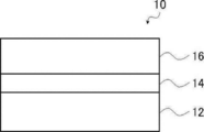
- FIG. 1 is a schematic cross-sectional view of an embodiment of a lithographic printing plate precursor according to the present disclosure.
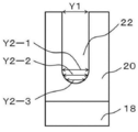
- FIG. 3 is a schematic cross-sectional view of one embodiment of an aluminum support having an anodized film. It is the schematic sectional drawing which expanded one of the micropores in FIG. 2A.
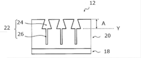
- FIG. 6 is a schematic cross-sectional view of another embodiment of an aluminum support having an anodized film.
- FIG. 6 is a schematic cross-sectional view of another embodiment of an aluminum support having an anodized film.
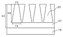
- FIG. 6 is a schematic cross-sectional view of another embodiment of an aluminum support having an anodized film.
- FIG. 6 is a schematic cross-sectional view of another embodiment of an aluminum support having an anodized film.
- FIG. 6 is a schematic cross-sectional view of another embodiment of an aluminum support having an anodized film.
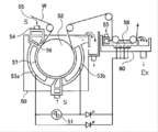
- FIG. 3 is a schematic cross-sectional view of an aluminum support having an anodic oxide coating, which shows a process sequence from a first anodizing process to a second anodizing process. It is a graph which shows an example of the alternating waveform current waveform diagram used for the electrochemical graining treatment in the manufacturing method of the aluminum support body which has an anodized film. It is a side view which shows an example of the radial type cell in the electrochemical graining treatment using alternating current in the manufacturing method of the aluminum support body which has an anodized film. It is a side view which shows the concept of the process of brush graining used for the mechanical roughening process in the manufacturing method of the aluminum support which has an anodized film.
- FIG. 3 is a schematic view of an anodizing apparatus used for anodizing in the method for producing an aluminum support having an anodized film.
- the “alkyl group” includes not only an alkyl group having no substituent (unsubstituted alkyl group) but also an alkyl group having a substituent (substituted alkyl group).
- (meth)acrylic is a term used as a concept including both acryl and methacryl
- (meth)acryloyl is a term used as a concept including both acryloyl and methacryloyl.
- the term “process” in the present specification refers to not only an independent process but also the case where it cannot be clearly distinguished from other processes as long as the intended purpose of the process is achieved. included.
- each component in the composition or each structural unit in the polymer may be contained alone or in combination of two or more.
- the amount of each component in the composition or each constituent unit in the polymer is such that there are a plurality of substances or constituent units corresponding to each component in the composition or each constituent unit in the polymer. In this case, unless otherwise specified, it means the total amount of the corresponding substances present in the composition or the respective constituent units present in the polymer.
- a combination of two or more preferable aspects is a more preferable aspect.
- the weight average molecular weight (Mw) and the number average molecular weight (Mn) in the present disclosure are columns of TSKgel GMHxL, TSKgel G4000HxL, and TSKgel G2000HxL (both manufactured by Tosoh Corp.) unless otherwise specified.
- the gel permeation chromatography (GPC) analyzer was used to detect the solvent THF (tetrahydrofuran) with a differential refractometer, and the molecular weight was calculated using polystyrene as a standard substance.
- the term “lithographic printing plate precursor” includes not only the lithographic printing plate precursor but also the discarded plate precursor.
- the term "lithographic printing plate” includes not only a lithographic printing plate precursor prepared through an operation such as exposure and development, but also a discarding plate, if necessary. In the case of a waste original plate, the operations of exposure and development are not always necessary.
- the waste plate is a lithographic printing plate precursor to be attached to a plate cylinder that is not used, for example, when printing a part of the paper surface in monochrome or two colors in color newspaper printing.
- “*” in the chemical structural formula represents a bonding position with another structure.
- the lithographic printing plate precursor according to the present disclosure has an image recording layer on a support, and the image recording layer contains an infrared absorber, a polymerization initiator, a polymerizable compound, and thermoplastic resin particles.
- the lithographic printing plate precursor according to the present disclosure is preferably a negative lithographic printing plate precursor.
- the lithographic printing plate precursor according to the present disclosure is preferably an on-press development type lithographic printing plate precursor.
- an infrared absorber In the image recording layer of the lithographic printing plate precursor according to the present disclosure, an infrared absorber, a polymerization initiator, a polymerizable compound, and a thermoplastic resin particles in combination, by thermal fusion between the thermoplastic resin particles.
- the polymerizable compound is polymerized while being mixed with the thermal fusion product of the thermoplastic resin particles, so that a stronger film is formed and the printing durability is excellent even when the UV ink is used.
- the fact that the number of plates that can be printed is large is said to be “excellent in printing durability.”
- printing durability when using UV ink is also referred to as “UV printing durability”.
- thermoplastic resin particles in the image-recording layer improves the hydrophobicity of the image area, in addition to heat fusion between the thermoplastic resin particles, the polymerizable resin particles are polymerized while being mixed with the heat fusion product of the thermoplastic resin particles. It is presumed that this is due to a synergistic effect of UV printing durability due to the formation of a stronger film by compound polymerization.
- the image recording layer of the lithographic printing plate precursor according to the present disclosure by combining the infrared absorber, the polymerization initiator, the polymerizable compound, and the thermoplastic resin particles, since a strong film is formed, It is presumed that it is also excellent in chemical properties. Further, for the same reason, it is presumed that the on-press developability (hereinafter, also referred to as “temporal on-press developability”) is likely to be excellent even after storage with time.
- the on-press developability hereinafter, also referred to as “temporal on-press developability”
- the lithographic printing plate precursor according to the present disclosure has an image recording layer formed on a support.
- the image recording layer in the present disclosure contains an infrared absorber, a polymerization initiator, a polymerizable compound, and thermoplastic resin particles.
- the image recording layer used in the present disclosure is preferably a negative image recording layer, and more preferably a water-soluble or water-dispersible negative image recording layer.
- the unexposed portion of the image recording layer can be removed with at least one of dampening water and printing ink.
- the image recording layer used in the present disclosure contains thermoplastic resin particles.
- the thermoplastic resin contained in the thermoplastic resin particles is not particularly limited, and examples thereof include polyethylene, polystyrene, polyvinyl chloride, polyvinylidene chloride, poly(meth)acrylic acid methyl, poly(meth)acrylic acid ethyl, and poly(meth)acrylic acid. ) Butyl acrylate, polyacrylonitrile, polyvinyl acetate, and their copolymers.
- the thermoplastic resin may be in a latex state.
- the thermoplastic resin according to the present disclosure is a resin that forms part or all of the hydrophobic film forming the recording layer by melting or softening the thermoplastic resin by the heat generated in the exposure step described below. Preferably.
- the thermoplastic resin includes a resin A having a structural unit formed of an aromatic vinyl compound and a structural unit having a cyano group.
- the resin A included in the thermoplastic resin preferably has a structural unit formed of an aromatic vinyl compound.
- the aromatic vinyl compound may be a compound having a structure in which a vinyl group is bound to an aromatic ring, and examples thereof include a styrene compound and a vinylnaphthalene compound, and a styrene compound is preferable, and styrene is more preferable.
- styrene compound examples include styrene, p-methylstyrene, p-methoxystyrene, ⁇ -methylstyrene, p-methyl- ⁇ -methylstyrene, ⁇ -methylstyrene and p-methoxy- ⁇ -methylstyrene.
- Styrene is preferred.
- vinylnaphthalene compound examples include 1-vinylnaphthalene, methyl-1-vinylnaphthalene, ⁇ -methyl-1-vinylnaphthalene, 4-methyl-1-vinylnaphthalene and 4-methoxy-1-vinylnaphthalene. -Vinylnaphthalene is preferred.
- constitutional unit formed by the aromatic vinyl compound is preferably a constitutional unit represented by the following formula A1.
- R A1 and R A2 each independently represent a hydrogen atom or an alkyl group
- Ar represents an aromatic ring group
- R A3 represents a substituent
- n represents an integer of 0 or more and the maximum number of substituents of Ar or less.
- R A1 and R A2 are each independently preferably a hydrogen atom or an alkyl group having 1 to 4 carbon atoms, more preferably a hydrogen atom or a methyl group, and both are hydrogen atoms. Is more preferable.
- Ar is preferably a benzene ring or a naphthalene ring, and more preferably a benzene ring.
- R A3 is preferably an alkyl group or an alkoxy group, more preferably an alkyl group having 1 to 4 carbon atoms or an alkoxy group having 1 to 4 carbon atoms, and a methyl group or a methoxy group. Is more preferable. In the formula A1, when the R A3 there are a plurality, plural of R A3 may be the same or may be different. In formula A1, n is preferably an integer of 0 to 2, more preferably 0 or 1, and further preferably 0.
- the content of the constituent unit formed by the aromatic vinyl compound is preferably larger than the content of the constituent unit having a cyano group described later from the viewpoint of ink receptivity. It is more preferably 15% by mass to 85% by mass, and further preferably 30% by mass to 70% by mass, based on the total mass of the thermoplastic resin.
- the resin A contained in the thermoplastic resin particles preferably contains a constitutional unit having a cyano group.
- the cyano group is usually preferably introduced into the resin A as a constitutional unit containing a cyano group, using a compound (monomer) having a cyano group.
- Examples of the compound having a cyano group include acrylonitrile compounds, and (meth)acrylonitrile is preferable.
- the structural unit having a cyano group is preferably a structural unit formed by an acrylonitrile compound, and more preferably a structural unit formed by (meth)acrylonitrile.
- a structural unit formed by the compound having a cyano group a structural unit represented by the following formula B1 is preferably exemplified.
- R B1 represents a hydrogen atom or an alkyl group.
- R B1 is preferably a hydrogen atom or an alkyl group having 1 to 4 carbon atoms, more preferably a hydrogen atom or a methyl group, and further preferably a hydrogen atom.
- the content of the structural unit having a cyano group in the resin A is preferably smaller than that formed by the above aromatic vinyl compound from the viewpoint of ink receptivity, and is 55% by mass to the total mass of the resin A. It is more preferably 90% by mass, and further preferably 60% by mass to 85% by mass.
- the constitutional unit of the aromatic vinyl compound and the constitutional unit having a cyano group contains a constitutional unit formed of an aromatic vinyl compound and a constitutional unit having a cyano group, the constitutional unit of the aromatic vinyl compound and the constitutional unit having a cyano group having a cyano group
- the content ratio is preferably 5:5 to 9:1 on a mass basis, and more preferably 6:4 to 8 : 2.
- the resin A contained in the thermoplastic resin particles preferably further has a structural unit formed of an N-vinyl heterocyclic compound from the viewpoint of UV printing durability and chemical resistance.
- N-vinyl heterocyclic compound examples include N-vinylpyrrolidone, N-vinylcarbazole, N-vinylpyrrole, N-vinylphenothiazine, N-vinylsuccinimide, N-vinylphthalimide, N-vinylcaprolactam, and N- Examples thereof include vinylimidazole, and N-vinylpyrrolidone is preferable.
- a structural unit formed by the N-vinyl heterocyclic compound a structural unit represented by the following formula C1 is preferably exemplified.
- Ar N represents a heterocyclic structure containing a nitrogen atom, a nitrogen atom in Ar N is bonded to the carbon atoms indicated by *.
- the heterocyclic structure represented by Ar N is preferably a pyrrolidone ring, a carbazole ring, a pyrrole ring, a phenothiazine ring, a succinimide ring, a phthalimide ring, a caprolactam ring, and an imidazole ring, and a pyrrolidone ring Is more preferable.
- the heterocyclic structure represented by Ar N may have a known substituent.
- the content of the structural unit formed by the N-vinyl heterocyclic compound in the resin A is preferably 5% by mass to 50% by mass, and 10% by mass to 40% by mass with respect to the total mass of the resin A. More preferably.
- the resin A contained in the thermoplastic resin particles may contain a structural unit having an acidic group, but from the viewpoint of on-press developability and ink receptivity, the resin A may not contain a structural unit having an acidic group.
- the content of the constituent unit having an acidic group in the thermoplastic resin is preferably 20% by mass or less, more preferably 10% by mass or less, and further preferably 5% by mass or less. preferable.
- the lower limit of the content is not particularly limited and may be 0% by mass.
- the acid value of the thermoplastic resin is preferably 160 mgKOH/g or less, more preferably 80 mgKOH/g or less, and further preferably 40 mgKOH/g or less.
- the lower limit of the acid value is not particularly limited and may be 0 mgKOH/g.
- the acid value is determined by the measuring method according to JIS K0070:1992.
- the resin A contained in the thermoplastic resin particles may contain a structural unit containing a hydrophobic group from the viewpoint of ink receptivity.
- the hydrophobic group include an alkyl group, an aryl group and an aralkyl group.
- the structural unit containing a hydrophobic group a structural unit formed by an alkyl(meth)acrylate compound, an aryl(meth)acrylate compound or an aralkyl(meth)acrylate compound is preferable, and a structural unit formed by an alkyl(meth)acrylate compound is preferable. Are more preferred.
- the alkyl group in the above alkyl (meth)acrylate compound preferably has 1 to 10 carbon atoms.
- the alkyl group may be linear or branched, and may have a cyclic structure.
- Examples of the alkyl (meth)acrylate compound include methyl (meth)acrylate, ethyl (meth)acrylate, propyl (meth)acrylate, cyclohexyl (meth)acrylate, 2-ethylhexyl (meth)acrylate and dicyclopentanyl (meth)acrylate. Is mentioned.
- the aryl group in the aryl (meth)acrylate compound preferably has 6 to 20 carbon atoms, and more preferably a phenyl group.
- the aryl group may have a known substituent.
- the aryl (meth)acrylate compound include phenyl (meth)acrylate.
- the carbon number of the alkyl group in the aralkyl (meth)acrylate compound is preferably 1-10.
- the alkyl group may be linear or branched, and may have a cyclic structure.
- the aryl group in the aralkyl(meth)acrylate compound preferably has 6 to 20 carbon atoms, and more preferably a phenyl group.
- Preferred examples of the aralkyl (meth)acrylate compound include benzyl (meth)acrylate.
- the content of the structural unit having a hydrophobic group in the resin A contained in the thermoplastic resin particles is preferably 5% by mass to 50% by mass, and 10% by mass to 30% by mass with respect to the total mass of the resin A. % Is more preferable.
- the thermoplastic resin contained in the thermoplastic resin particles preferably has a hydrophilic group from the viewpoint of UV printing durability and on-press development property.
- the hydrophilic group is not particularly limited as long as it has a hydrophilic structure, and examples thereof include an acid group such as a carboxy group, a hydroxy group, an amino group, a cyano group, and a polyalkylene oxide structure.
- the hydrophilic group is preferably a group having a polyalkylene oxide structure, a group having a polyester structure, or a sulfonic acid group, and has a polyalkylene oxide structure. It is more preferable that it is a group having or a sulfonic acid group, and it is further preferable that it is a group having a polyalkylene oxide structure.
- the polyalkylene oxide structure is preferably a polyethylene oxide structure, a polypropylene oxide structure, or a poly(ethylene oxide/propylene oxide) structure.
- the hydrophilic group preferably has a polypropylene oxide structure as a polyalkylene oxide structure, and more preferably has a polyethylene oxide structure and a polypropylene oxide structure.
- the number of alkylene oxide structures in the polyalkylene oxide structure is preferably 2 or more, more preferably 5 or more, further preferably 5 to 200, and 8 to 8 from the viewpoint of on-press developability. Particularly preferred is 150.
- the hydrophilic group is preferably a group represented by the following formula Z, and more preferably a group represented by the following formula Z.
- -Q-W-Y formula Z In formula Z, Q represents a divalent linking group, W represents a divalent group having a hydrophilic structure or a divalent group having a hydrophobic structure, and Y represents a monovalent group having a hydrophilic structure or Represents a monovalent group having a hydrophobic structure, provided that either W or Y has a hydrophilic structure.
- Q is preferably a divalent linking group having 1 to 20 carbon atoms, and more preferably a divalent linking group having 1 to 10 carbon atoms. Further, Q is preferably an alkylene group, an arylene group, an ester bond, an amide bond, or a group in which two or more thereof are combined, and more preferably a phenylene group, an ester bond, or an amide bond.
- the divalent group having a hydrophilic structure in W is preferably a polyalkyleneoxy group or a group in which —CH 2 CH 2 NR W — is bonded to one end of the polyalkyleneoxy group.
- R W represents a hydrogen atom or an alkyl group.
- the divalent group having a hydrophobic structure in W is —R WA —, —O—R WA —O—, —R W N—R WA —NR W —, —OOC—R WA —O—, or It is preferably —OOC—R WA —O—.
- Each R WA independently represents a linear, branched or cyclic alkylene group having 6 to 120 carbon atoms, a haloalkylene group having 6 to 120 carbon atoms, an arylene group having 6 to 120 carbon atoms, and an alcarylene having 6 to 120 carbon atoms.
- the monovalent group having a hydrophilic structure in Y of the above formula Z is OH, COOH, a polyalkyleneoxy group whose terminal is a hydrogen atom or an alkyl group, or a polyalkyleneoxy group whose terminal is a hydrogen atom or an alkyl group. It is preferably a group in which —CH 2 CH 2 N(R W )— is bonded to the other end of.
- the monovalent group having a hydrophobic structure in Y of the above formula Z is a linear, branched or cyclic alkyl group having 6 to 120 carbon atoms, a haloalkyl group having 6 to 120 carbon atoms, an aryl group having 6 to 120 carbon atoms, An alkaryl group having 6 to 120 carbon atoms (alkylaryl group), an aralkyl group having 6 to 120 carbon atoms, OR WB , COOR WB , or OOCR WB is preferable. Note that R WB represents an alkyl group having 6 to 20 carbon atoms.
- W is more preferably a divalent group having a hydrophilic structure
- Q is a phenylene group or an ester bond.
- W is a polyalkyleneoxy group
- Y is more preferably a polyalkyleneoxy group whose terminal is a hydrogen atom or an alkyl group.
- the resin A contained in the thermoplastic resin particles preferably contains a structural unit having a hydrophilic group from the viewpoint of improving UV printing durability, chemical resistance and on-press developability.
- the hydrophilic group include —OH, —CN, —CONR 1 R 2 , and —NR 2 COR 1 (R 1 and R 2 each independently represent a hydrogen atom, an alkyl group, an alkenyl group, or an aryl group. R 1 and R 2 may combine with each other to form a ring.) —NR 3 R 4 , —N + R 3 R 4 R 5 X — (R 3 to R 5 are each independently a carbon atom.
- a group represented by the following formula PO hydrophilic group such as a thermoplastic resin contained in the thermoplastic resin particles have preferably the like .
- hydrophilic groups a group represented by —CONR 1 R 2 or formula PO is preferable, and a group represented by formula PO is more preferable.
- L P each independently represents an alkylene group
- R P represents a hydrogen atom or an alkyl group
- n represents an integer of 1 to 100.
- L P is preferably each independently an ethylene group, a 1-methylethylene group or a 2-methylethylene group, and more preferably an ethylene group.
- R P is preferably a hydrogen atom or an alkyl group having 1 to 18 carbon atoms, more preferably a hydrogen atom or an alkyl group having 1 to 10 carbon atoms, and a hydrogen atom or 1 to 4 carbon atoms. Is more preferable, and a hydrogen atom or a methyl group is particularly preferable.
- n is preferably an integer of 1 to 10, more preferably an integer of 1 to 4.
- the content of the structural unit having a hydrophilic group in the resin A is preferably 5% by mass to 60% by mass, more preferably 10% by mass to 30% by mass, based on the total mass of the resin A. ..
- the resin A contained in the thermoplastic resin particles may further contain other constitutional units.
- a structural unit other than the above structural units can be contained without particular limitation, and examples thereof include structural units formed of an acrylamide compound, a vinyl ether compound, and the like.
- the acrylamide compound include (meth)acrylamide, N-methyl(meth)acrylamide, N-ethyl(meth)acrylamide, N-propyl(meth)acrylamide, N-butyl(meth)acrylamide, N,N′-dimethyl.
- Examples thereof include (meth)acrylamide, N,N′-diethyl(meth)acrylamide, N-hydroxyethyl(meth)acrylamide, N-hydroxypropyl(meth)acrylamide, N-hydroxybutyl(meth)acrylamide and the like.
- the vinyl ether compound include methyl vinyl ether, ethyl vinyl ether, propyl vinyl ether, n-butyl vinyl ether, tert-butyl vinyl ether, 2-ethylhexyl vinyl ether, n-nonyl vinyl ether, lauryl vinyl ether, cyclohexyl vinyl ether, cyclohexyl methyl vinyl ether, 4-methylcyclohexyl vinyl ether.
- the content of the other structural units in the thermoplastic resin is preferably 5% by mass to 50% by mass, more preferably 10% by mass to 30% by mass, based on the total mass of the thermoplastic resin.
- thermoplastic resin contained in thermoplastic resin particles The glass transition temperature (Tg) of the thermoplastic resin is preferably 60° C. to 150° C., more preferably 80° C. to 140° C., and more preferably 90° C. from the viewpoint of UV printing durability and ink receptivity. More preferably, the temperature is up to 130°C.
- Tg glass transition temperature
- the thermoplastic resin particles contain two or more types of thermoplastic resins, the value obtained by the FOX equation described later is called the glass transition temperature of the thermoplastic resin.
- the glass transition temperature of a resin can be measured using differential scanning calorimetry (DSC).
- DSC differential scanning calorimetry
- the specific measurement method is performed according to the method described in JIS K 7121 (1987) or JIS K 6240 (2011).
- Tig extrapolated glass transition start temperature
- the method for measuring the glass transition temperature will be described more specifically.
- the temperature is kept at about 50° C. lower than the expected Tg of the resin until the apparatus becomes stable, and then the heating rate is 20° C./min, and the temperature is about 30° C. lower than the temperature at which the glass transition is completed. Heat to high temperature and make a differential thermal analysis (DTA) or DSC curve.
- DTA differential thermal analysis
- the extrapolated glass transition onset temperature (Tig) that is, the glass transition temperature Tg in the present specification, is defined by a straight line obtained by extending a low temperature side baseline in the DTA curve or the DSC curve to a high temperature side and a stepwise change portion of the glass transition. It is calculated as the temperature at the intersection with the tangent line drawn at the point where the slope of the curve is maximum.
- the Tg of the thermoplastic resin contained in the thermoplastic resin particles is calculated as follows.
- the Tg of the first thermoplastic resin is Tg1(K)
- the mass fraction of the first thermoplastic resin to the total mass of the thermoplastic resin components in the thermoplastic resin particles is W1
- the second Tg is Tg2. (K) and when the mass fraction of the second resin with respect to the total mass of the thermoplastic resin components in the thermoplastic resin particles is W2, Tg0(K) of the thermoplastic resin particles is expressed by the following FOX equation. Therefore, it can be estimated.
- FOX formula: 1/Tg0 (W1/Tg1)+(W2/Tg2)
- Tg of the thermoplastic resin particles is n.
- Tgn(K) and the mass fraction of the n-th resin with respect to the total mass of the resin components in the thermoplastic resin particles is Wn, the estimation is performed according to the following equation, similarly to the above. Is possible.
- FOX formula: 1/Tg0 (W1/Tg1)+(W2/Tg2)+(W3/Tg3)...+(Wn/Tgn)
- Tg is a value measured by a differential scanning calorimetry (DSC).
- DSC differential scanning calorimeter
- EXSTAR 6220 manufactured by SII Nanotechnology Inc. can be used as the differential scanning calorimeter (DSC).
- thermoplastic resin particles The arithmetic average particle diameter of the thermoplastic resin particles is preferably 1 nm or more and 200 nm or less, more preferably 3 nm or more and less than 80 nm, and further preferably 10 nm or more and 49 nm or less from the viewpoint of UV printing durability. ..
- the arithmetic average particle diameter of the thermoplastic resin particles in the present disclosure refers to a value measured by a dynamic light scattering method (DLS) unless otherwise specified.
- the measurement of the arithmetic average particle diameter of the thermoplastic resin particles by DLS is performed using a Brookhaven BI-90 (manufactured by Brookhaven Instrument Company) according to the manual of the above equipment.
- the weight average molecular weight of the thermoplastic resin contained in the thermoplastic resin particles is preferably 3,000 to 300,000, and more preferably 5,000 to 100,000.
- thermoplastic resin contained in thermoplastic resin particles The method for producing the thermoplastic resin contained in the thermoplastic resin particles is not particularly limited and can be produced by a known method.
- a styrene compound, an acrylonitrile compound, and optionally the N-vinyl heterocyclic compound, the compound used for forming the structural unit having the ethylenically unsaturated group, and the compound used for forming the structural unit having the acidic group Known compound, at least one compound selected from the group consisting of the compound used for forming the structural unit having the hydrophobic group, and the compound used for forming the other structural unit. It is obtained by polymerizing.
- thermoplastic resin contained in the thermoplastic resin particles are shown in the table below, but the thermoplastic resin used in the present disclosure is not limited thereto.
- the content ratio of each structural unit can be appropriately changed according to the preferable range of the content of each structural unit described above.
- the weight average molecular weight of each compound shown in the above specific examples can be appropriately changed according to the preferable range of the weight average molecular weight of the thermoplastic resin.
- the image recording layer may contain one type of thermoplastic resin particles alone, or may use two or more types in combination.
- the content of the thermoplastic resin particles with respect to the total mass of the image recording layer is preferably 5% by mass or more and 90% by mass or less, more preferably 10% by mass or more and 80% by mass or less, from the viewpoint of UV printing durability. It is more preferably 10% by mass or more and 60% by mass or less.
- the image recording layer in the present disclosure contains a polymerizable compound.
- the polymerizable compound means a compound having a polymerizable group.
- the thermoplastic resin contained in the above-mentioned thermoplastic resin particles, the polymer particles described below, and the compound corresponding to the binder polymer other than the thermoplastic resin described below are polymerized. It does not correspond to a sex compound.
- the polymerizable group is not particularly limited as long as it is a known polymerizable group, but is preferably an ethylenically unsaturated group.
- the polymerizable group may be a radical polymerizable group or a cation polymerizable group, but is preferably a radical polymerizable group.
- the radically polymerizable group include a (meth)acryloyl group, an allyl group, a vinylphenyl group and a vinyl group, and a (meth)acryloyl group is preferable from the viewpoint of reactivity.
- the molecular weight (weight average molecular weight in the case of having a molecular weight distribution) of the polymerizable compound is preferably 50 or more and less than 2,500, and more preferably 50 or more and 2,000 or less.
- the molecular weight of the polymerizable compound is preferably 1,500 or less from the viewpoints of UV printing durability, ink receptivity, chemical resistance, and on-machine development of non-image area over time.
- the mass per 1 mol of ethylenically unsaturated bond in the polymerizable compound is 200 g/mol or less. Is preferred, 50 g/mol or more and 200 g/mol or less is more preferred, 80 g/mol or more and 180 g/mol or less is more preferred, and 100 g/mol or more and 150 g/mol or less is particularly preferred.
- the ethylenically unsaturated bond equivalent of the polymerizable compound can be specifically calculated as follows, for example.
- the polymerizable compound used in the present disclosure may be, for example, a radically polymerizable compound or a cationically polymerizable compound, but the addition polymerizable compound having at least one ethylenically unsaturated bond (ethylenic Unsaturated compounds) are preferred.
- the ethylenically unsaturated compound is preferably a compound having at least one terminal ethylenically unsaturated bond, and more preferably a compound having two or more terminal ethylenically unsaturated bonds.
- the polymerizable compound has a chemical form such as a monomer, a prepolymer, that is, a dimer, a trimer or an oligomer, or a mixture thereof.
- the polymerizable compound preferably contains a trifunctional or higher functional polymerizable compound from the viewpoint of UV printing durability, more preferably a 7-functional or higher functional polymerizable group, and a 10-functional or higher functional polymerizable compound. It is more preferable to include a group.
- the polymerizable compound preferably contains a trifunctional or higher functional ethylenically unsaturated compound (preferably 7 or higher functional, more preferably 10 or higher functional) from the viewpoint of UV printing durability of the lithographic printing plate obtained. It is further preferable to include a (meth)acrylate compound having a functionality of 3 or more (preferably 7 or more, more preferably 10 or more).
- the polymerizable compound contained in the image recording layer preferably contains an oligomer.
- an oligomer represents a polymerizable compound having a molecular weight (weight average molecular weight in the case of having a molecular weight distribution) of 600 or more and 10,000 or less and including at least one polymerizable group.
- the molecular weight of the oligomer is preferably 1,000 or more and 5,000 or less from the viewpoint of excellent chemical resistance, UV printing resistance, and suppression of on-press development residue.
- the number of polymerizable groups in one molecule of the oligomer is preferably 2 or more, more preferably 3 or more, and further preferably 6 or more. It is preferably 10 or more, and particularly preferably 10.
- the upper limit of the number of polymerizable groups in the oligomer is not particularly limited, but the number of polymerizable groups is preferably 20 or less.
- the oligomer has 7 or more polymerizable groups and a molecular weight of 1,000 or more and 10,000 or less. More preferably, the number of polymerizable groups is 7 or more and 20 or less, and the molecular weight is 1,000 or more and 5,000 or less.
- the oligomer preferably has at least one selected from the group consisting of a compound having a urethane bond, a compound having an ester bond and a compound having an epoxy residue. It is preferred to have compounds that have a bond.
- an epoxy residue refers to a structure formed by an epoxy group, and means, for example, a structure similar to the structure obtained by reacting an acid group (carboxylic acid group or the like) with an epoxy group.
- the compound having a urethane bond is not particularly limited, and examples thereof include a compound obtained by reacting a polyisocyanate compound with a compound having a hydroxy group and a polymerizable group.
- polyisocyanate compound examples include bifunctional to pentafunctional polyisocyanate compounds, and bifunctional or trifunctional polyisocyanate compounds are preferable.
- polyisocyanate compound examples include 1,3-bis(isocyanatomethyl)cyclohexane, isophorone diisocyanate, trimethylene diisocyanate, tetramethylene diisocyanate, pentamethylene diisocyanate, hexamethylene diisocyanate, 1,3-cyclopentane diisocyanate, 9H-fluorene- 2,7-diisocyanate, 9H-fluoren-9-one-2,7-diisocyanate, 4,4'-diphenylmethane diisocyanate, 1,3-phenylene diisocyanate, tolylene-2,4-diisocyanate, tolylene -2,6-diisocyanate, 1,3-bis(isocyanatomethyl)cyclohexane, 2,2-bis(4-bis
- the compound having a hydroxy group and a polymerizable group a compound having one hydroxy group and one or more polymerizable groups is preferable, and a compound having one hydroxy group and two or more polymerizable groups is more preferable.
- the compound having a hydroxy group and a polymerizable group include hydroxyethyl (meth)acrylate, glycerin di(meth)acrylate, trimethylolpropane di(meth)acrylate, pentaerythritol tri(meth)acrylate, dipentaerythritol penta(meth). Acrylate etc. are mentioned.
- the compound having a urethane bond is preferably, for example, a compound having at least a group represented by the following formula (Ac-1) or formula (Ac-2), and represented by the following formula (Ac-1).
- a compound having at least a group is more preferable.
- L 1 to L 4 each independently represent a divalent hydrocarbon group having 2 to 20 carbon atoms, and the wavy line portion represents a bonding position with another structure.
- L 1 to L 4 are each independently preferably an alkylene group having 2 to 20 carbon atoms, more preferably an alkylene group having 2 to 10 carbon atoms, and an alkylene group having 4 to 8 carbon atoms. More preferably, The alkylene group may have a branched or ring structure, but is preferably a straight chain alkylene group.
- the wavy line portion in the formula (Ac-1) or the formula (Ac-2) is preferably independently and directly bonded to the wavy line portion in the group represented by the following formula (Ae-1) or the formula (Ae-2). ..
- R's each independently represent an acryloyloxy group or a methacryloyloxy group
- the wavy line portion represents the wavy line portion in the formula (Ac-1) and the formula (Ac-2). Represents the binding position with.
- a compound obtained by introducing a polymerizable group into a polyurethane obtained by the reaction of a polyisocyanate compound and a polyol compound by a polymer reaction may be used.
- a compound having a urethane bond may be obtained by reacting a polyurethane oligomer obtained by reacting a polyisocyanate compound with a polyol compound having an acid group with a compound having an epoxy group and a polymerizable group.
- the number of polymerizable groups in the compound having an ester bond is preferably 3 or more, more preferably 6 or more.
- a compound containing a hydroxy group in the compound is preferable. Further, the number of polymerizable groups in the compound having an epoxy residue is preferably 2 to 6, and more preferably 2 to 3.
- the compound having an epoxy residue can be obtained, for example, by reacting a compound having an epoxy group with acrylic acid.
- the content of the oligomer in the image recording layer is 30% by mass to 100% by mass with respect to the total mass of the polymerizable compound. It is preferable that the amount is 50% by mass to 100% by mass, further preferably 80% by mass to 100% by mass.
- the polymerizable compound may further contain a polymerizable compound other than the oligomer.
- the polymerizable compound other than the oligomer may be, for example, a radically polymerizable compound or a cationically polymerizable compound, but an addition polymerizable compound having at least one ethylenically unsaturated group (ethylenically unsaturated compound ) Is preferable.
- the ethylenically unsaturated compound is preferably a compound having at least one ethylenically unsaturated group at the terminal, and more preferably a compound having at least two ethylenically unsaturated groups at the terminal.
- the polymerizable compound other than the oligomer is preferably a low molecular weight polymerizable compound from the viewpoint of chemical resistance.
- the low molecular weight polymerizable compound may be in a chemical form such as a monomer, a dimer, a trimer or a mixture thereof.
- the low molecular weight polymerizable compound refers to a polymerizable compound having a molecular weight (weight average molecular weight in the case of having a molecular weight distribution) of 50 or more and less than 600.
- the molecular weight of the low molecular weight polymerizable compound is preferably 100 or more and less than 600, and more preferably 300 or more and less than 600 from the viewpoint of excellent chemical resistance, UV printing durability, and suppression of on-press development dust. It is more preferably 400 or more and less than 600.
- the ratio of the oligomer to the low molecular weight polymerizable compound is preferably from 10/1 to 1/10 on a mass basis. It is more preferably 1 to 3/7, further preferably 10/1 to 7/3.
- Examples of the polymerizable compound include unsaturated carboxylic acids (for example, acrylic acid, methacrylic acid, itaconic acid, crotonic acid, isocrotonic acid, maleic acid, etc.) and their esters and amides. Esters of saturated carboxylic acids and polyhydric alcohol compounds, and amides of unsaturated carboxylic acids and polyhydric amine compounds are used.
- unsaturated carboxylic acids for example, acrylic acid, methacrylic acid, itaconic acid, crotonic acid, isocrotonic acid, maleic acid, etc.
- Esters of saturated carboxylic acids and polyhydric alcohol compounds, and amides of unsaturated carboxylic acids and polyhydric amine compounds are used.
- a dehydration condensation reaction product with a polyfunctional carboxylic acid is also preferably used.
- a substitution reaction product of an unsaturated carboxylic acid ester or amide having a leaving substituent such as a tosyloxy group and a monofunctional or polyfunctional alcohol, amine, or thiol is also suitable.
- JP-A-2006-508380 JP-A-2002-287344, JP-A-2008-256850, JP-A-2001-342222, JP-A-9-179296, and JP-A-9-179297.
- JP-A-9-179298 JP-A-2004-294935, JP-A-2006-243493, JP-A-2002-275129, JP-A-2003-64130, JP-A-2003-280187, and It is described in, for example, Kaihei 10-333321.
- the monomer of the ester of a polyhydric alcohol compound and an unsaturated carboxylic acid include acrylic acid esters such as ethylene glycol diacrylate, 1,3-butanediol diacrylate, tetramethylene glycol diacrylate, propylene glycol diacrylate, There are trimethylolpropane triacrylate, hexanediol diacrylate, tetraethylene glycol diacrylate, pentaerythritol tetraacrylate, sorbitol triacrylate, isocyanuric acid ethylene oxide (EO) modified triacrylate, polyester acrylate oligomer and the like.
- acrylic acid esters such as ethylene glycol diacrylate, 1,3-butanediol diacrylate, tetramethylene glycol diacrylate, propylene glycol diacrylate,
- EO isocyanuric acid ethylene oxide
- methacrylic acid ester As methacrylic acid ester, tetramethylene glycol dimethacrylate, neopentyl glycol dimethacrylate, trimethylolpropane trimethacrylate, ethylene glycol dimethacrylate, pentaerythritol trimethacrylate, bis[p-(3-methacryloxy-2-hydroxypropoxy)phenyl] Examples include dimethyl methane and bis[p-(methacryloxyethoxy)phenyl]dimethyl methane.
- amide monomer of a polyvalent amine compound and an unsaturated carboxylic acid examples include methylenebisacrylamide, methylenebismethacrylamide, 1,6-hexamethylenebisacrylamide, 1,6-hexamethylenebismethacrylamide, Examples include diethylenetriamine tris acrylamide, xylylene bis acrylamide, and xylylene bis methacrylamide.
- urethane-based addition-polymerizable compounds produced by addition reaction of isocyanate and hydroxy group are also suitable, and specific examples thereof include, for example, 2 molecules per molecule described in JP-B-48-41708.
- Vinyl urethane compound containing two or more polymerizable vinyl groups in one molecule obtained by adding a vinyl monomer containing a hydroxy group represented by the following formula (M) to a polyisocyanate compound having two or more isocyanate groups Etc.
- CH 2 C(R M4 )COOCH 2 CH(R M5 )OH (M)
- R M4 and R M5 each independently represent a hydrogen atom or a methyl group.
- oligomer As the oligomer, a commercially available product may be used, such as UA510H, UA-306H, UA-306I, UA-306T (all manufactured by Kyoeisha Chemical Co., Ltd.), UV-1700B, UV-6300B, UV7620EA (all manufactured by Japan Chemical Industry Co., Ltd.), U-15HA (Shin-Nakamura Chemical Industry Co., Ltd.), EBECRYL450, EBECRYL657, EBECRYL885, EBECRYL800, EBECRYL3416, EBECRYL860 (all manufactured by Daicel Ornex Co., Ltd.) and the like. It is not limited to this.
- the image recording layer preferably contains two or more kinds of polymerizable compounds from the viewpoint of UV printing durability.
- the content of the polymerizable compound (when two or more polymerizable compounds are contained, the total content of the polymerizable compounds) is preferably 5% by mass to 75% by mass with respect to the total mass of the image recording layer. It is more preferably 10% by mass to 70% by mass, and further preferably 15% by mass to 60% by mass.
- the content of the thermoplastic resin contained in the thermoplastic resin particles with respect to the total mass of the polymerizable compound in the image recording layer is preferably more than 0 mass% and 400 mass% or less, and 25 mass% to 300 mass%. It is more preferably mass%, and even more preferably 50 mass% to 200 mass%.
- the thermoplastic resin contained in the thermoplastic resin particles and the polymerizable compound preferably have a sea-island structure.
- the image recording layer used in the present disclosure contains a polymerization initiator.
- the polymerizable initiator is not particularly limited, and examples thereof include an electron accepting polymerization initiator and an electron donating polymerization initiator.
- the image recording layer preferably contains an electron-accepting polymerization initiator.
- the electron-accepting polymerization initiator used in the present disclosure is a compound that generates a polymerization initiation species such as a radical or a cation by the energy of light, heat or both, and is a known thermal polymerization initiator and has a small bond dissociation energy. A compound having a bond, a photopolymerization initiator and the like can be appropriately selected and used.
- the electron-accepting polymerization initiator is preferably a radical polymerization initiator, more preferably an onium compound. Further, the electron-accepting polymerization initiator is preferably an infrared-sensitive polymerization initiator.
- the electron-accepting polymerization initiators may be used alone or in combination of two or more.
- the radical polymerization initiator for example, (a) organic halide, (b) carbonyl compound, (c) azo compound, (d) organic peroxide, (e) metallocene compound, (f) azide compound, (g) ) Hexaarylbiimidazole compounds, (i) disulfone compounds, (j) oxime ester compounds, and (k) onium compounds.
- organic halide (a) for example, compounds described in paragraphs 0022 to 0023 of JP-A-2008-195018 are preferable.
- (b) carbonyl compound for example, compounds described in paragraph [0024] of JP-A-2008-195018 are preferable.
- the azo compound (c) for example, the azo compounds described in JP-A-8-108621 can be used.
- the organic peroxide (d) for example, compounds described in paragraph [0025] of JP-A-2008-195018 are preferable.
- (e) metallocene compound for example, the compounds described in JP-A-2008-195018, paragraph 0026 are preferable.
- Examples of the (f) azide compound include compounds such as 2,6-bis(4-azidobenzylidene)-4-methylcyclohexanone.
- Examples of the (g) hexaarylbiimidazole compound for example, the compounds described in paragraph 0027 of JP-A-2008-195018 are preferable.
- Examples of the (i) disulfone compound include compounds described in JP-A Nos. 61-166544 and 2002-328465.
- As the oxime ester compound (j) for example, compounds described in paragraphs 0028 to 0030 of JP-A-2008-195018 are preferable.
- oxime ester compounds and onium compounds are preferable from the viewpoint of curability.
- an iodonium salt compound, a sulfonium salt compound or an azinium salt compound is preferable, an iodonium salt compound or a sulfonium salt compound is more preferable, and an iodonium salt compound is still more preferable.
- Specific examples of these compounds are shown below, but the present disclosure is not limited thereto.
- a diaryliodonium salt compound is preferable, and a diphenyliodonium salt compound substituted with an electron-donating group, for example, an alkyl group or an alkoxyl group is more preferable, and an asymmetric diphenyliodonium salt compound is preferable. ..
- diphenyliodonium hexafluorophosphate
- 4-methoxyphenyl-4-(2-methylpropyl)phenyliodonium hexafluorophosphate
- 4-(2-methylpropyl)phenyl-p-tolyliodonium hexa Fluorophosphate
- 4-hexyloxyphenyl-2,4,6-trimethoxyphenyliodonium hexafluorophosphate
- 4-hexyloxyphenyl-2,4-diethoxyphenyliodonium tetrafluoroborate
- 4-octyloxy Phenyl-2,4,6-trimethoxyphenyliodonium 1-perfluorobutanesulfonate
- 4-octyloxyphenyl-2,4,6-trimethoxyphenyliodonium hexafluorophosphate
- Iodonium hexafluorophosphat
- a triarylsulfonium salt compound is preferable, and particularly an electron-withdrawing group, for example, a triarylsulfonium salt compound in which at least a part of the group on the aromatic ring is substituted with a halogen atom is preferable, and an aromatic compound.
- bis(4-chlorophenyl)phenylsulfonium benzoyl formate
- bis(4-chlorophenyl)-4-methylphenylsulfonium tetrafluoro Borate
- tris(4-chlorophenyl)sulfonium 3,5-bis(methoxycarbonyl)benzenesulfonate
- tris(4-chlorophenyl)sulfonium hexafluorophosphate
- a sulfonamide anion or a sulfonimide anion is preferable, and a sulfonimide anion is more preferable.
- the sulfonamide anion is preferably an aryl sulfonamide anion.
- a bisarylsulfonimide anion is preferable. Specific examples of the sulfonamide anion or sulfonimide anion are shown below, but the present disclosure is not limited thereto. In the following specific examples, Ph represents a phenyl group, Me represents a methyl group, and Et represents an ethyl group.
- the electron-accepting polymerization initiator is a compound represented by the following formula (I) from the viewpoints of color developability, color developability after exposure, developability, and UV printing durability of the resulting lithographic printing plate precursor. Can be preferably used.
- X represents a halogen atom, and specific examples thereof include a fluorine atom, a chlorine atom, a bromine atom and an iodine atom. Of these, a chlorine atom or a bromine atom is preferable because of its excellent sensitivity, and a bromine atom is particularly preferable.
- A represents a divalent linking group selected from the group consisting of —CO—, —SO—, —SO 2 —, —PO— and —PO 2 —. Of these, —CO—, —SO— and —SO 2 — are more preferred, and —CO— and —SO 2 — are particularly preferred.
- R X1 and R X2 each independently represent a hydrogen atom or a monovalent hydrocarbon group having 1 to 20 carbon atoms.
- Examples of the hydrocarbon that constitutes the hydrocarbon group include the hydrocarbons described in paragraphs 0013 to 0014 of JP-A-2002-162741, and specifically, the hydrocarbons include methane and ethane.
- substituents examples include a monovalent non-metal atomic group other than hydrogen, a halogen atom (-F, -Br, -Cl, -I), a hydroxyl group, an alkoxy group, an aryloxy group, a mercapto group, an alkylthio group.
- arylthio group alkyldithio group, aryldithio group, amino group, N-alkylamino group, N,N-dialkylamino group, N-arylamino group, N,N-diarylamino group, N-alkyl-N- Arylamino group, acyloxy group, carbamoyloxy group, N-alkylcarbamoyloxy group, N-arylcarbamoyloxy group, N,N-dialkylcarbamoyloxy group, N,N-diarylcarbamoyloxy group, N-alkyl-N-aryl Rucarbamoyloxy group, alkylsulfoxy group, arylsulfoxy group, acylthio group, acylamino group, N-alkylacylamino group, N-arylacylamino group, ureido group, N'-alkylureido group, N',N,N
- substituents may combine with each other or with the hydrocarbon group which is substituting to form a ring, and the substituent may be further substituted.
- Preferred substituents include a halogen atom, an alkoxy group, an aryloxy group, an alkyl group, an alkenyl group, an alkynyl group and an aryl group.
- the compounds represented by the following formulas (II) and (III) are preferable because they are excellent in visibility.
- X has the same meaning as in formula (I), and R 3 , R 4 and R 5 are each independently a monovalent hydrocarbon having 1 to 20 carbon atoms. Represents a group.
- R 3 , R 4 and R 5 are preferably aryl groups, and those in which the aryl group is substituted with an amide group are more preferable because of excellent balance between sensitivity and storage stability.
- the compound represented by the formula (IV) is particularly preferable.
- R 4 and R 5 each independently represent a hydrogen atom or a monovalent hydrocarbon group having 1 to 20 carbon atoms.
- Specific examples of the electron-accepting polymerization initiator represented by the above formula (I) include compounds represented by the following formulas, but the present disclosure is not limited thereto.
- the lowest unoccupied molecular orbit (LUMO) of the electron-accepting polymerization initiator is preferably ⁇ 3.00 eV or less, and more preferably ⁇ 3.02 eV or less, from the viewpoint of chemical resistance and UV printing durability. Further, the lower limit is preferably ⁇ 3.80 eV or more, and more preferably ⁇ 3.60 eV or more.
- the content of the electron accepting polymerization initiator is preferably 0.1% by mass to 50% by mass, more preferably 0.5% by mass to 30% by mass, based on the total mass of the image recording layer. It is particularly preferably 0.8% by mass to 20% by mass.
- the polymerization initiator preferably further contains an electron donating polymerization initiator from the viewpoint of contributing to improvement in chemical resistance in the lithographic printing plate and UV printing durability, and the electron donating polymerization initiator and the electron donating agent described above. It is more preferable to include both type polymerization initiators.
- Examples of the electron-donating polymerization initiator include the following 5 types.
- (Ii) Aminoacetic acid compound It is considered that the C—X bond on the carbon adjacent to the nitrogen is cleaved by oxidation to generate an active radical.
- X is preferably a hydrogen atom, a carboxy group, a trimethylsilyl group or a benzyl group. Specific examples thereof include N-phenylglycines (which may have a substituent on the phenyl group), N-phenyliminodiacetic acid (which may have a substituent on the phenyl group), and the like. Be done.
- Sulfur-containing compound A compound in which the nitrogen atom of the above-mentioned aminoacetic acid compound is replaced by a sulfur atom can generate an active radical by the same action.
- Tin-containing compound A compound in which the nitrogen atom of the above-mentioned aminoacetic acid compound is replaced with a tin atom can generate an active radical by the same action.
- Sulfinates An active radical can be generated by oxidation. Specific examples include sodium arylsulfinate and the like.
- the image recording layer preferably contains a borate compound.
- a borate compound a tetraarylborate compound or a monoalkyltriarylborate compound is preferable, a tetraarylborate compound is more preferable, and a tetraphenylborate compound is particularly preferable, from the viewpoint of the stability of the compound.
- the counter cation contained in the borate compound is not particularly limited, but is preferably an alkali metal ion or a tetraalkylammonium ion, and more preferably a sodium ion, a potassium ion or a tetrabutylammonium ion.
- sodium tetraphenylborate is preferably mentioned as a borate compound.
- the highest occupied molecular orbital (HOMO) of the electron-donating polymerization initiator used in the present disclosure is preferably ⁇ 6.00 eV or more from the viewpoint of chemical resistance and UV printing durability, and ⁇ 5.95 eV. More preferably, it is more preferably ⁇ 5.93 eV or more.
- the upper limit is preferably ⁇ 5.00 eV or less, more preferably ⁇ 5.40 eV or less.
- the highest occupied orbit (HOMO) and the lowest unoccupied orbit (LUMO) are calculated by the following method.
- Quantum chemical calculation software Gaussian09 is used, and structural optimization is performed by DFT(B3L YP/6-31G(d)).
- the MO energy Ebare (unit: hartree) obtained by the MO energy calculation is converted into Escaled (unit: eV) used as the values of HOMO and LUMO in the present disclosure by the following formula.
- Escaled 0.823168 ⁇ 27.2114 ⁇ Ebare ⁇ 1.07634 Note that 27.2114 is a coefficient for simply converting heartree into eV, 0.823168 and -1.07634 are adjustment coefficients, and HOMO and LUMO of the compound to be calculated are calculated values. To suit.
- the electron donative polymerization initiator examples include B-1 to B-8 and other compounds, but needless to say, the present invention is not limited to these.
- Bu represents an n-butyl group and Z represents a counter cation.
- the counter cation represented by Z + include Na + , K + , N + (Bu) 4, and the like.
- the above Bu represents an n-butyl group.
- an onium ion in the electron-accepting type polymerization initiator is also suitably exemplified.
- the content of the electron-donating polymerization initiator is preferably 0.01% by mass to 30% by mass, more preferably 0.05% by mass to 25% by mass, and 0.1% by mass with respect to the total mass of the image recording layer. More preferably, it is from about 20% by mass.
- one of the preferable embodiments in the present disclosure is an embodiment in which the electron accepting polymerization initiator and the electron donating polymerization initiator form a salt.
- the onium compound is a salt of an onium ion and an anion (for example, tetraphenylborate anion) in the electron donating polymerization initiator can be mentioned.
- an iodonium borate compound in which an iodonium cation (for example, di-p-tolyl iodonium cation) in the iodonium salt compound and a borate anion in the electron donating polymerization initiator form a salt Specific examples of the mode in which the electron accepting polymerization initiator and the electron donating polymerization initiator form a salt are shown below, but the present disclosure is not limited thereto.
- the image recording layer when the image recording layer contains an onium ion and the anion in the above-mentioned electron donating polymerization initiator, the image recording layer shall contain an electron accepting polymerization initiator and the above electron donating polymerization initiator. ..
- the image recording layer contains an infrared absorber.
- the infrared absorber is not particularly limited, and examples thereof include pigments and dyes.
- the dye used as the infrared absorbing agent a commercially available dye and known dyes described in documents such as "Dye Handbook” (edited by Organic Synthetic Chemistry Society, published in 1970) can be used.
- azo dyes metal complex salt azo dyes, pyrazolone azo dyes, naphthoquinone dyes, anthraquinone dyes, phthalocyanine dyes, carbonium dyes, quinone imine dyes, methine dyes, cyanine dyes, squarylium dyes, pyrylium salts, metal thiolate complex dyes, etc. Is mentioned.
- cyanine dyes particularly preferred among these dyes are cyanine dyes, squarylium dyes, pyrylium salts, nickel thiolate complexes, and indolenine cyanine dyes. Furthermore, cyanine dyes and indolenine cyanine dyes can be mentioned. Of these, cyanine dyes are particularly preferable.
- the above-mentioned infrared absorber is preferably a cationic polymethine dye having an oxygen or nitrogen atom at the meso position.
- Preferred examples of the cationic polymethine dye include a cyanine dye, a pyrylium dye, a thiopyrylium dye, and an azurenium dye, and the cyanine dye is preferred from the viewpoints of easy availability and solvent solubility during the introduction reaction.
- cyanine dye examples include compounds described in paragraphs 0017 to 0019 of JP 2001-133969 A, paragraphs 0016 to 0021 of JP 2002-023360 A, and paragraphs 0012 to 0037 of JP 2002-040638 A.
- the compounds described in paragraphs 0008 to 0009 of JP-A-5-5005 and paragraphs 0022 to 0025 of JP-A 2001-222101 can also be preferably used.
- the compounds described in paragraphs 0072 to 0076 of JP-A-2008-195018 are preferable.
- the infrared absorbent is preferably a decomposable infrared absorbent.
- a decomposable infrared absorbent dye as the infrared absorbent, the infrared absorbent or a decomposition product thereof accelerates polymerization, and by using the thermoplastic resin, a highly polar film can be obtained.
- the UV printing durability is excellent due to the interaction between the decomposition product of the infrared absorbent and the polymerizable compound.
- the decomposable infrared absorbing agent is preferably an infrared absorbing agent having a function of absorbing infrared rays by being exposed to infrared rays, decomposing, and developing a color.
- coloring means that there is almost no absorption in the visible light region (wavelength region of 400 nm or more and less than 750 nm) before infrared exposure, but absorption occurs in the visible light region by infrared exposure. It also includes absorption in the lower wavelength region having a longer wavelength in the visible light region.
- the compound that is formed by the decomposable infrared absorber absorbing infrared rays by infrared exposure and decomposed to form a color is also referred to as a "coloring substance of the decomposable infrared absorber".
- the decomposable infrared absorbent has a function of absorbing infrared rays by infrared exposure and converting the absorbed infrared rays into heat.
- the decomposable infrared absorbing agent may be one that absorbs and decomposes at least part of light in the infrared wavelength range (wavelength 750 nm to 1 mm), but infrared rays having a maximum absorption in the wavelength range 750 nm to 1400 nm. It is preferably an absorbent.
- the decomposable infrared absorbing agent is preferably an infrared absorbing agent that decomposes due to heat due to infrared exposure, electron transfer or both, and more preferably an infrared absorbing agent that decomposes due to electron transfer due to infrared exposure.
- “decomposes by electron transfer” means that an electron excited by HOMO (highest occupied molecular orbital) of a decomposable infrared absorbent to LUMO (lowest unoccupied molecular orbital) by infrared exposure is an electron accepting group (LUMO) in the molecule. And a group close to the electric potential), which means that intramolecular electron transfer occurs and decomposition occurs accordingly.
- the decomposable infrared absorber a cyanine dye that decomposes by infrared exposure is preferable from the viewpoint of color developability and UV printing durability of the lithographic printing plate obtained.
- the infrared absorber is preferably a compound represented by the following formula 1-1.
- R 1 represents a group in which the R 1 -L bond is cleaved by infrared exposure
- R 11 to R 18 are each independently a hydrogen atom, a halogen atom, —Ra, —ORb, —SRc or — represents NRdRe
- Ra ⁇ Re each independently represent a hydrocarbon group
- a 1 and A 2 each independently represents an oxygen atom, a sulfur atom or a nitrogen atom
- n 11 and n 12 each independently represent an integer of 0 to 5, provided that the total of n 11 and n 12 is 2 or more.
- N 13 and n 14 each independently represent 0 or 1
- L represents an oxygen atom, a sulfur atom or —NR 10 —
- R 10 represents a hydrogen atom, an alkyl group or an aryl group
- Za represents a charge. Represents a counterion that neutralizes.
- the cyanine dye represented by Formula 1-1 When the cyanine dye represented by Formula 1-1 is exposed to infrared rays, the R 1 -L bond is cleaved, and L becomes ⁇ O, ⁇ S, or ⁇ NR 10 to give a decomposable infrared absorber. A chromophore is formed. R 1 leaves to form a radical body or an ionic body. These contribute to the polymerization of the polymerizable compound contained in the image recording layer.
- R 11 to R 18 are preferably each independently a hydrogen atom, —Ra, —ORb, —SRc or —NRdRe.
- the hydrocarbon group in Ra to Re is preferably a hydrocarbon group having 1 to 30 carbon atoms, more preferably a hydrocarbon group having 1 to 15 carbon atoms, and further preferably a hydrocarbon group having 1 to 10 carbon atoms.
- the hydrocarbon group may have a straight chain structure, a branched structure, or a ring structure.
- R 11 to R 14 in Formula 1-1 are each independently preferably a hydrogen atom or a hydrocarbon group, more preferably a hydrogen atom or an alkyl group, and further preferably a hydrogen atom.
- R 11 and R 13 which are bonded to the carbon atom to which L is bonded are preferably an alkyl group, and it is more preferred that both are bonded to form a ring.
- the formed ring is preferably a 5-membered ring or a 6-membered ring, more preferably a 5-membered ring.
- R 12 bound to the carbon atom to which A 1 + is bound and R 14 bound to the carbon atom to which A 2 is bound are preferably linked to R 15 and R 17 , respectively, to form a ring.
- R 15 in Formula 1-1 is preferably a hydrocarbon group. Further, it is preferable that R 15 and R 12 bonded to the carbon atom to which A 1 + is bonded are linked to each other to form a ring.
- the ring formed is preferably an indolium ring, a pyrylium ring, a thiopyrylium ring, a benzoxazoline ring or a benzimidazoline ring, and more preferably an indolium ring from the viewpoint of color development.
- R 17 in Formula 1-1 is preferably a hydrocarbon group. Further, it is preferable that R 17 and R 14 bonded to the carbon atom to which A 2 is bonded are linked to each other to form a ring.
- the ring formed is preferably an indole ring, a pyran ring, a thiopyran ring, a benzoxazole ring, or a benzimidazole ring, and more preferably an indole ring from the viewpoint of color development.
- R 15 and R 17 in Formula 1-1 are preferably the same group, and when they form a ring, they preferably form the same ring.
- R 16 and R 18 in formula 1-1 are preferably the same group. Further, from the viewpoint of improving the water solubility of the compound represented by formula 1-1, R 16 and R 18 are each independently preferably a alkyl group having a (poly)oxyalkylene group or an alkyl group having an anion structure, An alkyl group having an alkoxyalkyl group, a carboxylate group or a sulfonate group is more preferable, and an alkyl group having a sulfonate group at the terminal is further preferable. As the alkyl group, an alkyl group having 1 to 10 carbon atoms is preferable, and an alkyl group having 1 to 4 carbon atoms is more preferable.
- the counter cation having the above anion structure may be a cation that may be contained in R 1 -L in Formula 1-1 or A 1 + , or may be an alkali metal cation or an alkaline earth metal cation.
- the counter cation of the sulfonate group may be a cation or A 1 + that may be contained in R 1 -L in formula 1-1, or may be an alkali metal cation or an alkaline earth metal cation.
- R 16 and R 18 are each independently an alkyl group or an aromatic group from the viewpoint of increasing the maximum absorption wavelength of the compound represented by Formula 1-1 to a longer wavelength, and from the viewpoint of color developability and printing durability in a lithographic printing plate.
- An alkyl group having a ring is preferable.
- an alkyl group having 1 to 10 carbon atoms is preferable, an alkyl group having 1 to 4 carbon atoms is more preferable, and a methyl group or an ethyl group is further preferable.
- an alkyl group having an aromatic ring an alkyl group having an aromatic ring at the terminal is preferable, and a 2-phenylethyl group, a 2-naphthalenylethyl group or a 2-(9-anthracenyl)ethyl group is more preferable.
- n 11 and n 12 are preferably the same integer of 0 to 5, more preferably 1 to 3, further preferably 1 or 2, and particularly preferably 2.
- a 1 and A 2 in Formula 1-1 each independently represent an oxygen atom, a sulfur atom or a nitrogen atom, and a nitrogen atom is preferable.
- a 1 and A 2 in Formula 1-1 are preferably the same atom.
- Za in Formula 1-1 represents a counter ion that neutralizes charge.
- sulfonate ion, carboxylate ion, tetrafluoroborate ion, hexafluorophosphate ion, p-toluenesulfonate ion, perchlorate ion and the like can be mentioned, and hexafluorophosphate ion is preferable.
- an alkali metal ion, an alkaline earth metal ion, an ammonium ion, a pyridinium ion, a sulfonium ion and the like can be mentioned, and a sodium ion, a potassium ion, an ammonium ion, a pyridinium ion or a sulfonium ion is preferable, and a sodium ion, More preferred are potassium ions or ammonium ions.
- R 11 to R 18 and R 1 -L may have an anion structure or a cation structure, and if all of R 11 to R 18 and R 1 -L are charge neutral groups, Za Is a monovalent counter anion, but if it has two or more anionic structures in R 11 to R 18 and R 1 -L, Za can also be a counter cation. If the cyanine dye represented by Formula 1-1 has a charge-neutral structure in the entire compound, Za does not exist.
- a cyanine dye represented by the following formula 1-A is more preferable from the viewpoints of color developability and UV printing durability of the lithographic printing plate obtained.
- R 1 represents a group in which the R 1 -L bond is cleaved by infrared exposure
- R 2 and R 3 each independently represent a hydrogen atom or an alkyl group
- R 2 and R 3 are linked to each other.
- Ar 1 and Ar 2 each independently represent a group that forms a benzene ring or a naphthalene ring
- Y 1 and Y 2 each independently represent an oxygen atom, a sulfur atom, or —NR 0 -or a dialkylmethylene group
- R 0 represents a hydrogen atom, an alkyl group or an aryl group
- R 4 and R 5 each independently represent an alkyl group, a —CO 2 M group or a —PO 3 M 2 group.
- M represents a hydrogen atom, Na atom, K atom or onium group
- R 6 to R 9 each independently represents a hydrogen atom or an alkyl group
- L represents an oxygen atom, a sulfur atom or —NR 10 —
- R 10 represents a hydrogen atom, an alkyl group or an aryl group
- Za represents a counter ion that neutralizes the charge.
- the alkyl group for R 2 to R 9 and R 0 is preferably an alkyl group having 1 to 30 carbon atoms, more preferably an alkyl group having 1 to 15 carbon atoms, and an alkyl group having 1 to 10 carbon atoms. Is more preferable.
- the alkyl group may have a straight chain structure, a branched structure, or a ring structure.
- eicosyl group isopropyl group, isobutyl group, s-butyl group, tert-butyl group, isopentyl group, neopentyl group, 1-methylbutyl group, isohexyl group, 2-ethylhexyl group, 2-methylhexyl group, cyclohexyl group, cyclopentyl group And a 2-norbornyl group.
- alkyl groups a methyl group, an ethyl group, a propyl group or a butyl group is preferable.
- the above alkyl group may have a substituent.
- substituents include an alkoxy group, aryloxy group, amino group, alkylthio group, arylthio group, halogen atom, carboxy group, carboxylate group, sulfo group, sulfonate group, alkyloxycarbonyl group, aryloxycarbonyl group, and The group etc. which combined these are mentioned.
- the aryl group for R 0 is preferably an aryl group having 6 to 30 carbon atoms, more preferably an aryl group having 6 to 20 carbon atoms, and further preferably an aryl group having 6 to 12 carbon atoms.
- the aryl group may have a substituent. Examples of the substituent include an alkyl group, an alkoxy group, an aryloxy group, an amino group, an alkylthio group, an arylthio group, a halogen atom, a carboxy group, a carboxylate group, a sulfo group, a sulfonate group, an alkyloxycarbonyl group and an aryloxycarbonyl group. , And groups combining these.
- aryl groups a phenyl group, a p-methoxyphenyl group, a p-dimethylaminophenyl group or a naphthyl group is preferable.
- R 2 and R 3 are preferably linked to each other to form a ring.
- R 2 and R 3 are linked to form a ring, a 5-membered ring or a 6-membered ring is preferable, and a 5-membered ring is particularly preferable.
- Y 1 and Y 2 each independently represent an oxygen atom, a sulfur atom, —NR 0 — or a dialkylmethylene group, preferably —NR 0 — or a dialkylmethylene group, and more preferably a dialkylmethylene group.
- R 0 represents a hydrogen atom, an alkyl group or an aryl group, and an alkyl group is preferable.
- the alkyl group represented by R 4 or R 5 may be substituted alkyl.
- Examples of the substituted alkyl group represented by R 4 or R 5 include groups represented by any of the following formulas (a1) to (a4).
- R W0 represents an alkylene group having 2 to 6 carbon atoms
- W represents a single bond or an oxygen atom
- n W1 represents an integer of 1 to 45
- R W1 represents carbon.
- R W5 represents an alkyl group having 1 to 12 carbons
- R W2 to R W4 each independently represents a single bond or 1 carbon
- M represents a hydrogen atom, a Na atom, a K atom or an onium group.
- alkylene group represented by R W0 in the formula (a1) examples include an ethylene group, an n-propylene group, an isopropylene group, an n-butylene group, an isobutylene group, an n-pentylene group, an isopentylene group, and an n- Examples thereof include a hexyl group and an isohexyl group, with an ethylene group, an n-propylene group, an isopropylene group and an n-butylene group being preferred, and an n-propylene group being particularly preferred.
- n W1 is preferably 1 to 10, more preferably 1 to 5, and particularly preferably 1 to 3.
- alkyl group represented by R W1 examples include methyl group, ethyl group, n-propyl group, isopropyl group, n-butyl group, isobutyl group, tert-butyl group, n-pentyl group, isopentyl group, neopentyl group.
- Methyl group, ethyl group, n-propyl group, isopropyl group, n-butyl group, tert-butyl group are preferable, and methyl group, An ethyl group is more preferable, and a methyl group is particularly preferable.
- the alkyl group represented by R W5 is the same as the alkyl group represented by R W1 and the preferred embodiments are also the same as the preferred embodiments of the alkyl group represented by R W1 .
- alkylene group represented by R W2 to R W4 examples include methylene group, ethylene group, n-propylene group, isopropylene group, n-butylene group, isobutylene group. , N-pentylene group, isopentylene group, n-hexyl group, isohexyl group, n-octylene group, n-dodecylene group and the like, ethylene group, n-propylene group, isopropylene group, n-butylene group are preferable, An ethylene group and an n-propylene group are particularly preferable.
- two existing Ms may be the same or different.
- examples of the onium group represented by M include an ammonium group, an iodonium group, a phosphonium group and a sulfonium group.
- R 4 and R 5 are preferably each an unsubstituted alkyl group. R 4 and R 5 are preferably the same group.
- R 6 to R 9 each independently represent a hydrogen atom or an alkyl group, and preferably a hydrogen atom.
- Ar 1 and Ar 2 each independently represent a group forming a benzene ring or a naphthalene ring. The benzene ring and naphthalene ring may have a substituent.
- substituent examples thereof include groups, phosphonic acid groups, and groups in which these are combined.
- the substituent is preferably an alkyl group.
- Ar 1 and Ar 2 are each independently a naphthalene ring. , Or, preferably a group forming a benzene ring having an alkyl group or an alkoxy group as a substituent, more preferably a naphthalene ring, or a group forming a benzene ring having an alkoxy group as a substituent, a naphthalene ring, or methoxy.
- a group forming a benzene ring having a group as a substituent is particularly preferable.
- Ar 1 or Ar 2 is preferably a group forming a group represented by the following formula (b1).
- R 19 represents an alkyl group having 1 to 12 carbon atoms.
- n3 represents an integer of 1 to 4. * Represents a binding site.
- Za represents a counter ion for neutralizing the electric charge.
- Za represents an anionic species, examples thereof include a sulfonate ion, a carboxylate ion, a tetrafluoroborate ion, a hexafluorophosphate ion, a p-toluenesulfonate ion, and a perchlorate ion, and a hexafluorophosphate ion is preferable.
- Za represents a cationic species
- examples thereof include an alkali metal ion, an alkaline earth metal ion, an ammonium ion, a pyridinium ion or a sulfonium ion, and a sodium ion
- a potassium ion, an ammonium ion, a pyridinium ion or a sulfonium ion is preferable, and sodium is used.
- Ions, potassium ions or ammonium ions are more preferred.
- R 1 to R 9 , R 0 , Ar 1 , Ar 2 , Y 1 and Y 2 may have an anion structure or a cation structure, and R 1 to R 9 , R 0 , Ar 1 , Ar 2 and When Y 1 and Y 2 are all charge-neutral groups, Za is a monovalent counter anion, and for example, R 1 to R 9 , R 0 , Ar 1 , Ar 2 , Y 1 and When Y 2 has two or more anionic structures, Za can also be a counter cation.
- R 1 -L bond is described below based on the cleaved by infrared exposure represented by R 1.
- R 1 is a group represented by any one of the following formulas (1-1) to (1-7) from the viewpoint of color developability. Are preferred, and groups represented by any of the following formulas (1-1) to (1-3) are more preferred.
- ⁇ represents a bonding site with the oxygen atom represented by L in formula 1-1 or formula 1-A
- R 20 independently represents hydrogen.
- each R 21 independently represents a hydrogen atom, an alkyl group or an aryl group
- R 22 is an aryl group.
- R 23 represents an aryl group, an alkenyl group, an alkoxy group or Represents an onium group
- R 24 to R 27 each independently represents a hydrogen atom, an alkyl group or an aryl group
- R 28 represents an alkyl group, an aryl group, —OR 24 , —NR 25 R 26 or —SR 27 .
- Z 1 represents a counter ion for neutralizing the charge.
- R 20 , R 21 and R 24 to R 28 are alkyl groups are the same as the preferred embodiments of the alkyl groups in R 2 to R 9 and R 0 .
- the carbon number of the alkenyl group in R 20 and R 23 is preferably 1 to 30, more preferably 1 to 15, and further preferably 1 to 10.
- the preferred embodiment when R 20 to R 28 are aryl groups is the same as the preferred embodiment of the aryl group for R 0 .
- R 20 in formula (1-1) is preferably an alkyl group, an alkenyl group, an aryl group, —OR 24 , —NR 25 R 26 or —SR 27 , and an alkyl group, —OR 24 , — NR 25 R 26 or —SR 27 is more preferable, an alkyl group or —OR 24 is further preferable, and —OR 24 is particularly preferable.
- the alkyl group may be an alkyl group having an arylthio group, an alkyloxycarbonyl group, or an arylsulfonyl group at the ⁇ -position.
- R 20 in the formula (1-1) is —OR 24
- R 24 is preferably an alkyl group, more preferably an alkyl group having 1 to 8 carbon atoms, further preferably an isopropyl group or a tert-butyl group, and t -Butyl group is particularly preferred.
- R 20 in formula (1-1) is an alkenyl group
- the alkenyl group may be an aryl group or an alkenyl group having a hydroxyaryl group.
- R 21 in formula (1-2) is preferably a hydrogen atom.
- R 22 in formula (1-2) is preferably —C( ⁇ O)OR 24 , —OC( ⁇ O)OR 24 or a halogen atom, and —C( ⁇ O)OR 24. Or, —OC( ⁇ O)OR 24 is more preferable.
- R 24 is preferably an alkyl group.
- each R 21 in formula (1-3) is independently preferably a hydrogen atom or an alkyl group, and at least one R 21 in formula (1-3) is more preferably an alkyl group.
- the alkyl group for R 21 is preferably an alkyl group having 1 to 10 carbon atoms, and more preferably an alkyl group having 3 to 10 carbon atoms.
- the alkyl group for R 21 is preferably an alkyl group having a branched or cyclic structure, more preferably an isopropyl group, a cyclopentyl group, a cyclohexyl group, or a tert-butyl group.
- the alkyl group for R 21 is preferably a secondary or tertiary alkyl group.
- R 23 in formula (1-3) is preferably an aryl group, an alkoxy group or an onium group, more preferably a p-dimethylaminophenyl group or a pyridinium group, and even more preferably a pyridinium group.
- Examples of the onium group for R 23 include a pyridinium group, an ammonium group and a sulfonium group.
- the onium group may have a substituent.
- alkyl groups, aryl groups, and groups in which these are combined include alkyl groups, aryl groups, and groups in which these are combined.
- a pyridinium group is preferred, and an N-alkyl-3-pyridinium group, an N-benzyl-3-pyridinium group, an N-(alkoxypolyalkyleneoxyalkyl)-3-pyridinium group, an N-alkoxycarbonylmethyl-3-pyridinium group.
- N-alkyl-4-pyridinium group, N-benzyl-4-pyridinium group, N-(alkoxypolyalkyleneoxyalkyl)-4-pyridinium group, N-alkoxycarbonylmethyl-4-pyridinium group, or N-alkyl -3,5-dimethyl-4-pyridinium group is more preferable, N-alkyl-3-pyridinium group or N-alkyl-4-pyridinium group is further preferable, N-methyl-3-pyridinium group, N-octyl group A -3-pyridinium group, an N-methyl-4-pyridinium group or an N-octyl-4-pyridinium group is particularly preferable, and an N-octyl-3-pyridinium group or an N-octyl-4-pyridinium group is the most preferable.
- examples of the counter anion include a sulfonate ion, a carboxylate ion, a tetrafluoroborate ion, a hexafluorophosphate ion, a p-toluenesulfonate ion, and a perchlorate ion.
- -Toluenesulfonate ion or hexafluorophosphate ion are preferred.
- R 20 in formula (1-4) is preferably an alkyl group or an aryl group, and more preferably one of the two R 20 is an alkyl group and the other is an aryl group.
- the two R 20 s may be linked to each other to form a ring.
- R 20 in formula (1-5) is preferably an alkyl group or an aryl group, more preferably an aryl group, and further preferably a p-methylphenyl group.
- each R 20 in formula (1-6) is preferably an alkyl group or an aryl group, more preferably a methyl group or a phenyl group.
- Z 1 in formula (1-7) may be a counter ion for neutralizing charge, and the compound as a whole may be contained in Za.
- Z 1 is preferably a sulfonate ion, a carboxylate ion, a tetrafluoroborate ion, a hexafluorophosphate ion, a p-toluenesulfonate ion or a perchlorate ion, and a p-toluenesulfonate ion or a hexafluorophosphate ion is preferable. More preferable.
- R 1 is more preferably a group represented by the following formula (5), from the viewpoint of color developability.
- R 15 and R 16 each independently represent a hydrogen atom, an alkyl group or an aryl group
- E represents an onium group
- * represents L in formula 1-1 or formula 1-A. Represents the binding site with the oxygen atom.
- the alkyl group represented by R 15 or R 16 is the same as the alkyl group in R 2 to R 9 and R 0 , and the preferred embodiment is also the same as the preferred embodiment of the alkyl group in R 2 to R 9 and R 0 . ..
- the aryl group represented by R 15 or R 16 is the same as the aryl group for R 0 , and the preferred embodiments are also the same as the preferred embodiments for the aryl group for R 0 .
- the onium group represented by E is the same as the onium group for R 23 , and the preferred embodiment is also the same as the preferred embodiment of the onium group for R 23 .
- the onium group represented by E is preferably a pyridinium group represented by the following formula (6).
- R 17 represents a halogen atom, an alkyl group, an aryl group, hydroxy group or alkoxy group, if R 17 there are a plurality, the plurality of R 17 may be the same or different, or a plurality of R 17 may combine to form a ring.
- n2 represents an integer of 0 to 4.
- R 18 represents an alkyl group or an aryl group.
- Z b represents a counter ion for neutralizing the electric charge.
- the alkyl group or aryl group represented by R 17 or R 18 is the same as the alkyl group in R 2 to R 9 and R 0 or the aryl group in R 0 , and a preferable embodiment is also in R 2 to R 9 and R 0 . It is the same as the preferable embodiment of the alkyl group or the aryl group for R 0 .
- the alkoxy group represented by R 17 is preferably an alkoxy group having 1 to 10 carbon atoms, and includes a methoxy group, an ethoxy group, an n-propoxy group, an isopropoxy group, an n-butoxy group, an isobutoxy group and a tert-butoxy group. Can be mentioned.
- n2 is preferably 0.
- the counter ion for neutralizing the charge represented by Z b is the same as Z 1 in formula (1-7), and the preferred embodiment is also the same as the preferred embodiment of Z 1 in formula (1-7). ..
- TsO ⁇ represents a tosylate anion
- ⁇ represents a bonding site with the oxygen atom represented by L in formula 1-1 or formula 1-A.
- R 1 is an oxygen atom and R 1 is an aryl group or a linear alkyl group, cleavage of the R 1 —O bond due to infrared exposure does not occur.
- R 1 is preferably a group represented by the following formula (2-1).
- ⁇ represents a binding site to the sulfur atom represented by L in formula 1-1 or formula 1-A
- R 21's each independently represent a hydrogen atom, an alkyl group or aryl. It represents a group
- R 22 represents an aryl group, an alkenyl group, an alkoxy group or an onium group.
- R 1 bonded to N is preferably a group represented by Formula (3-1) below.
- ⁇ represents a bonding site with the nitrogen atom contained in L in formula 1-1 or formula 1-A, and X 1 and X 2 are each independently an oxygen atom or a sulfur atom.
- Y represents a group represented by the above formula (2-1).
- the alkyl group, aryl group, alkenyl group, alkoxy group and onium group represented by R 21 and R 22 are represented by the above formula (1-1) to formula (1-7).
- the description regarding the alkyl group, the aryl group, the alkenyl group, the alkoxy group, and the onium group described above can be incorporated.
- L represents a sulfur atom or —NR 10 — and R 10 represents a hydrogen atom, an alkyl group or an aryl group, from the viewpoint of improving printing durability.
- R 1 in Formula 1-1 and Formula 1-A is preferably a group represented by Formula 2 below. Further, the group represented by the above formula 2 is preferably a group in which the R Z —O bond in the formula 2 is cleaved by infrared exposure.
- R Z represents an alkyl group
- the wavy line portion represents a binding site to the group represented by L in Formula 1-1 or Formula 1-A.
- the alkyl group represented by R Z is the same as the preferred embodiments of the alkyl group for R 2 to R 9 and R 0 described above. From the viewpoint of color developability and UV printing durability of the resulting lithographic printing plate, the alkyl group is preferably a secondary alkyl group or a tertiary alkyl group, and a tertiary alkyl group. Is preferred.
- the alkyl group is preferably an alkyl group having 1 to 8 carbon atoms, and a branched alkyl group having 3 to 10 carbon atoms.
- An alkyl group is more preferable, a branched chain alkyl group having 3 to 6 carbon atoms is further preferable, an isopropyl group or a tert-butyl group is particularly preferable, and a t-butyl group is most preferable.
- ⁇ represents a binding site to L in formula 1-1 or formula 1-A.
- infrared absorbers that decompose by infrared exposure will be given below, but the present disclosure is not limited thereto.
- infrared absorbing agent which decomposes by infrared exposure
- those described in Japanese Patent Publication No. 2008-544322 or International Publication No. 2016/027886 can be preferably used.
- the content of the infrared absorbent in the image recording layer is preferably 0.1% by mass to 10.0% by mass, more preferably 0.5% by mass to 5.0% by mass, based on the total mass of the image recording layer. preferable.
- the image recording layer in the present disclosure contains the electron-donating polymerization initiator, the electron-accepting polymerization initiator, and the infrared absorber, and the electron-donating polymerization initiator has a HOMO of ⁇ 6.0 eV or more.
- the LUMO of the electron-accepting polymerization initiator is preferably ⁇ 3.0 eV or less. More preferable embodiments of the HOMO of the electron donating polymerization initiator and the LUMO of the electron accepting polymerization initiator are as described above.
- the electron donating polymerization initiator, the infrared absorbing agent, and the electron accepting polymerization initiator for example, transfer energy as described in the following chemical formula. Guessed. Therefore, if the HOMO of the electron-donating polymerization initiator is ⁇ 6.0 eV or more and the LUMO of the electron-accepting polymerization initiator is ⁇ 3.0 eV or less, the radical generation efficiency is improved, It is considered that it is more likely to have excellent chemical resistance and UV printing durability.
- the difference between the HOMO of the electron-donating polymerization initiator and the HOMO of the infrared absorber is preferably 1.00 eV or less, and 0.700 eV or less. Is more preferable. From the same viewpoint, the difference between the HOMO of the electron-donating polymerization initiator and the HOMO of the infrared absorber is preferably ⁇ 0.200 eV or more, and more preferably ⁇ 0.100 eV or more. preferable.
- the difference between the HOMO of the electron-donating polymerization initiator and the HOMO of the infrared absorber is preferably 1.00 eV to ⁇ 0.200 eV, and 0.700 eV to ⁇ 0. More preferably, it is 100 eV.
- a negative value means that the HOMO of the electron-donating polymerization initiator is higher than the HOMO of the infrared absorber.
- the difference between the LUMO of the infrared absorber and the LUMO of the electron-accepting polymerization initiator is preferably 1.00 eV or less, and 0.700 eV or less. Is more preferable.
- the difference between the LUMO of the infrared absorber and the LUMO of the electron-accepting polymerization initiator is preferably ⁇ 0.200 eV or more, and more preferably ⁇ 0.100 eV or more. preferable.
- the difference between the LUMO of the infrared absorber and the LUMO of the electron-accepting polymerization initiator is preferably 1.00 eV to ⁇ 0.200 eV, and 0.700 eV to ⁇ 0. More preferably, it is 100 eV.
- a negative value means that the LUMO of the infrared absorber is higher than the LUMO of the electron-accepting polymerization initiator.
- the image recording layer may contain polymer particles other than the thermoplastic resin particles.
- the image recording layer preferably contains polymer particles having a hydrophilic group from the viewpoint of UV printing durability and on-press development property.
- the hydrophilic group is not particularly limited as long as it has a hydrophilic structure, and examples thereof include an acid group such as a carboxy group, a hydroxy group, an amino group, a cyano group, and a polyalkylene oxide structure.
- the hydrophilic group is preferably a group having a polyalkylene oxide structure, a group having a polyester structure, or a sulfonic acid group, and has a polyalkylene oxide structure. It is more preferable that it is a group having or a sulfonic acid group, and it is further preferable that it is a group having a polyalkylene oxide structure.
- the polyalkylene oxide structure is preferably a polyethylene oxide structure, a polypropylene oxide structure, or a poly(ethylene oxide/propylene oxide) structure.
- the hydrophilic group preferably has a polypropylene oxide structure as a polyalkylene oxide structure, and more preferably has a polyethylene oxide structure and a polypropylene oxide structure.
- the number of alkylene oxide structures in the polyalkylene oxide structure is preferably 2 or more, more preferably 5 or more, further preferably 5 to 200, and 8 to 8 from the viewpoint of on-press developability. Particularly preferred is 150.
- the polymer particles are preferably selected from the group consisting of heat-reactive polymer particles, polymer particles having a polymerizable group, microcapsules containing a hydrophobic compound, and microgel (crosslinked polymer particles). Of these, polymer particles or microgels having a polymerizable group are preferable. In a particularly preferred embodiment, the polymer particles contain at least one ethylenically unsaturated polymerizable group. The presence of such polymer particles has the effect of enhancing the UV printing durability of the exposed area and the on-press developability of the unexposed area.
- the heat-reactive polymer particles include polymer particles having a heat-reactive group.
- the heat-reactive polymer particles form a hydrophobized region due to cross-linking due to heat reaction and a change in functional group at that time.
- the heat-reactive group in the polymer particles having a heat-reactive group may be a functional group that carries out any reaction as long as a chemical bond is formed, but it is preferably a polymerizable group.
- Ethylenically unsaturated group eg, acryloyl group, methacryloyl group, vinyl group, allyl group, etc.
- cationically polymerizable group eg, vinyl group, vinyloxy group, epoxy group, oxetanyl group, etc.
- the microcapsule for example, as described in JP 2001-277740 A and JP 2001-277742 A, at least a part of the components of the image recording layer is encapsulated in a microcapsule.
- the constituent components of the image recording layer may be contained outside the microcapsules.
- a preferred embodiment of the image recording layer containing microcapsules has a structure in which a hydrophobic constituent component is encapsulated in the microcapsule and a hydrophilic constituent component is contained outside the microcapsule.
- the microgel (crosslinked polymer particles) can contain a part of the components of the image recording layer on at least one of the surface and the inside thereof.
- a reactive microgel having a radically polymerizable group on its surface is preferable from the viewpoint of image forming sensitivity and UV printing durability.
- a publicly known method can be applied to microencapsulate or microgel the constituent components of the image recording layer.
- a polyvalent isocyanate which is an adduct of a polyphenol compound having two or more hydroxy groups in the molecule and isophorone diisocyanate. Those obtained by the reaction of the compound and the compound having active hydrogen are preferable.
- the polyhydric phenol compound is preferably a compound having a plurality of benzene rings having a phenolic hydroxy group.
- the compound having active hydrogen is preferably a polyol compound or a polyamine compound, more preferably a polyol compound, and further preferably at least one compound selected from the group consisting of propylene glycol, glycerin and trimethylolpropane.
- particles of a resin obtained by reacting a polyhydric isocyanate compound, which is an adduct of a polyhydric phenol compound having two or more hydroxy groups in the molecule, with isophorone diisocyanate, and a compound having active hydrogen there are disclosed in JP-A-2012-2012.
- Polymer particles described in paragraphs 0032 to 0095 of JP-A-206495 are preferable.
- the polymer particle has a hydrophobic main chain from the viewpoint of UV printing resistance and solvent resistance, and i) a constituent unit having a pendant cyano group directly bonded to the hydrophobic main chain, and , Ii) It is preferable to include both of the constituent units having a pendant group containing a hydrophilic polyalkylene oxide segment.
- Preferred examples of the hydrophobic main chain include acrylic resin chains.
- Preferred examples of the pendant cyano group include -[CH 2 CH(C ⁇ N)-] or -[CH 2 C(CH 3 )(C ⁇ N)-].
- the constituent unit having the pendant cyano group can be easily derived from an ethylenically unsaturated monomer such as acrylonitrile or methacrylonitrile, or a combination thereof.
- the alkylene oxide in the hydrophilic polyalkylene oxide segment is preferably ethylene oxide or propylene oxide, more preferably ethylene oxide.
- the number of repeating alkylene oxide structures in the hydrophilic polyalkylene oxide segment is preferably 10 to 100, more preferably 25 to 75, and even more preferably 40 to 50.
- the resin-containing particles include those described in paragraphs 0039 to 0068 of JP-A-2008-503365.
- the average particle size of the polymer particles is preferably 0.01 ⁇ m to 3.0 ⁇ m, more preferably 0.03 ⁇ m to 2.0 ⁇ m, still more preferably 0.10 ⁇ m to 1.0 ⁇ m. In this range, good resolution and stability over time can be obtained.
- the average primary particle diameter of each of the particles in the present disclosure is measured by a light scattering method, or an electron micrograph of the particles is taken, and the particle diameters of the particles are measured in total of 5,000 particles, and the average value is obtained. The value shall be calculated.
- the particle size is the particle size of spherical particles having the same particle area as that on the photograph.
- the average particle diameter in the present disclosure is a volume average particle diameter unless otherwise specified.
- the content of the polymer particles is preferably 5% by mass to 90% by mass with respect to the total mass of the image recording layer.
- the image recording layer used in the present disclosure preferably further contains an acid color former.
- the “acid color former” used in the present disclosure means a compound having a property of developing a color by heating while receiving an electron-accepting compound (for example, a proton of an acid or the like).
- the acid colorant has a partial skeleton such as lactone, lactam, sultone, spiropyran, ester, amide, etc., and is a colorless ring which rapidly opens or cleaves these partial skeletons when contacted with an electron accepting compound. Compounds are preferred.
- Such an acid color former examples include 3,3-bis(4-dimethylaminophenyl)-6-dimethylaminophthalide (referred to as "crystal violet lactone") and 3,3-bis(4- Dimethylaminophenyl)phthalide, 3-(4-dimethylaminophenyl)-3-(4-diethylamino-2-methylphenyl)-6-dimethylaminophthalide, 3-(4-dimethylaminophenyl)-3-(1 ,2-Dimethylindol-3-yl)phthalide, 3-(4-dimethylaminophenyl)-3-(2-methylindol-3-yl)phthalide, 3,3-bis(1,2-dimethylindole-3) -Yl)-5-dimethylaminophthalide, 3,3-bis(1,2-dimethylindol-3-yl)-6-dimethylaminophthalide, 3,3-bis(9-ethylcarbazol-3-
- the acid color former used in the present disclosure may be at least one compound selected from the group consisting of spiropyran compounds, spirooxazine compounds, spirolactone compounds, and spirolactam compounds, from the viewpoint of color developability.
- the hue of the dye after color development is preferably green, blue or black from the viewpoint of visibility.
- the acid color developing agent such as ETAC, RED500, RED520, CVL, S-205, BLACK305, BLACK400, BLACK100, BLACK500, H-7001, GREEN300, NIRBLACK78, BLUE220, H. -3035, BLUE203, ATP, H-1046, H-2114 (all manufactured by Fukui Yamada Chemical Co., Ltd.), ORANGE-DCF, Vermilion-DCF, PINK-DCF, RED-DCF, BLMB, CVL, GREEN-DCF.
- ETAC RED500, RED520, CVL
- S-205 BLACK305, BLACK400, BLACK100, BLACK500, H-7001, GREEN300, NIRBLACK78, BLUE220, H. -3035, BLUE203, ATP, H-1046, H-2114 (all manufactured by Fukui Yamada Chemical Co., Ltd.)
- ORANGE-DCF Vermilion-DCF
- PINK-DCF PINK-D
- TH-107 above, Hodogaya Chemical Co., Ltd.
- Examples include -118, Red-40, Red-8 (all manufactured by Yamamoto Kasei Co., Ltd.), and crystal violet lactone (manufactured by Tokyo Chemical Industry Co., Ltd.).
- ETAC, S-205, BLACK305, BLACK400, BLACK100, BLACK500, H-7001, GREEN300, NIRBLACK78, H-3035, ATP, H-1046, H-2114, GREEN-DCF, Blue-63. , GN-169, and crystal violet lactone are preferable because the film formed has good visible light absorption.
- the acid color formers may be used alone or in combination of two or more kinds.
- the content of the acid color former is preferably 0.5% by mass to 10% by mass, more preferably 1% by mass to 5% by mass, based on the total mass of the image recording layer.
- the image recording layer may contain a binder polymer other than the thermoplastic resin particles (hereinafter, also referred to as “other binder polymer”).
- the thermoplastic resin particles and the polymer particles do not correspond to the other binder polymer. That is, the other binder polymer is a polymer that is not in particle form.
- the other binder polymer a (meth)acrylic resin, a polyvinyl acetal resin, or a polyurethane resin is preferable.
- binder polymer known binder polymers used in the image recording layer of the lithographic printing plate precursor can be preferably used.
- the binder polymer used in the on-press development type lithographic printing plate precursor (hereinafter, also referred to as binder polymer for on-press development) will be described in detail.
- the binder polymer for on-press development is preferably a binder polymer having an alkylene oxide chain.
- the binder polymer having an alkylene oxide chain may have a poly(alkylene oxide) moiety in the main chain or in a side chain.
- graft polymer having a poly(alkylene oxide) in the side chain may be a block copolymer of a block composed of a poly(alkylene oxide)-containing repeating unit and a block composed of a (alkylene oxide)-free repeating unit.
- a polyurethane resin is preferred when it has a poly(alkylene oxide) moiety in the main chain.
- the main chain polymer having a poly(alkylene oxide) moiety in the side chain includes (meth)acrylic resin, polyvinyl acetal resin, polyurethane resin, polyurea resin, polyimide resin, polyamide resin, epoxy resin, polystyrene resin, and novolak type. Phenolic resins, polyester resins, synthetic rubbers and natural rubbers are mentioned, and (meth)acrylic resins are particularly preferable.
- a polyfunctional thiol having a functionality of 6 or more and a functionality of 10 or less is used as a nucleus, and the nucleus has a polymer chain bonded to the nucleus by a sulfide bond, and the polymer chain has a polymerizable group.
- examples thereof include a polymer compound (hereinafter, also referred to as a star polymer compound).
- a star polymer compound for example, the compounds described in JP 2012-148555 A can be preferably used.
- the star-shaped polymer compound has a polymerizable group such as an ethylenically unsaturated bond for improving the film strength of the image portion as described in JP-A-2008-195018, which is a main chain or a side chain, preferably a side chain. Those that are included in the chain are mentioned.
- the polymerizable groups form crosslinks between polymer molecules and accelerate curing.
- the polymerizable group is preferably an ethylenically unsaturated group such as a (meth)acrylic group, a vinyl group, an allyl group, a vinylphenyl group (styryl group) or an epoxy group, and a (meth)acrylic group, a vinyl group or a vinylphenyl group.
- a group (styryl group) is more preferable from the viewpoint of polymerization reactivity, and a (meth)acrylic group is particularly preferable.
- These groups can be introduced into the polymer by polymer reaction or copolymerization. For example, a reaction between a polymer having a carboxy group in its side chain and glycidyl methacrylate, or a reaction between a polymer having an epoxy group and an ethylenically unsaturated group-containing carboxylic acid such as methacrylic acid can be used. You may use these groups together.
- the weight average molecular weight (Mw) as a polystyrene-converted value by the GPC method is preferably 2,000 or more, more preferably 5,000 or more, and 10,000 to 300, It is more preferably 000.
- hydrophilic polymers such as polyacrylic acid and polyvinyl alcohol described in JP-A-2008-195018 can be used in combination. Also, a lipophilic polymer and a hydrophilic polymer can be used in combination.
- other binder polymers may be used alone or in combination of two or more.
- the other binder polymer may be contained in the image recording layer in an arbitrary amount, but the content of the binder polymer is 1% by mass to 90% by mass with respect to the total mass of the image recording layer. It is more preferably 5% by mass to 80% by mass.
- the content of the other binder polymer relative to the total mass of the thermoplastic resin particles and the other binder polymer is more than 0% by mass and 99% by mass or less. Is preferred, 20% by mass to 95% by mass is more preferred, and 40% by mass to 90% by mass is even more preferred.
- the image recording layer used in the present disclosure may contain a chain transfer agent.
- the chain transfer agent contributes to the improvement of UV printing durability in the planographic printing plate.
- a thiol compound is preferable, a thiol compound having 7 or more carbon atoms is more preferable from the viewpoint of boiling point (difficult to volatilize), and a compound having a mercapto group on the aromatic ring (aromatic thiol compound) is further preferable. ..
- the thiol compound is preferably a monofunctional thiol compound.
- chain transfer agents include the following compounds.
- the chain transfer agent may be added alone or in combination of two or more kinds.
- the content of the chain transfer agent is preferably 0.01% by mass to 50% by mass, more preferably 0.05% by mass to 40% by mass, and 0.1% by mass to 30% by mass with respect to the total mass of the image recording layer. % Is more preferable.
- the image recording layer preferably further contains an oil sensitizer in order to improve ink receptivity.
- the SP value of the oil sensitizer is preferably less than 18.0, more preferably 14 to less than 18, more preferably 15 to 17, and particularly 16 to 16.9. preferable.
- the oil sensitizer may be a compound having a molecular weight (weight average molecular weight when there is a molecular weight distribution) of 2,000 or more, or a compound having a molecular weight of less than 2,000.
- the Hansen solubility parameter is used.
- the Hansen solubility parameter is obtained by dividing the solubility parameter introduced by Hildebrand into three components of a dispersion term ⁇ d, a polar term ⁇ p, and a hydrogen bond term ⁇ h, and expressing them in a three-dimensional space.
- the SP value is represented by ⁇ (unit: (MPa) 1/2 ) and the value calculated using the following formula is used.
- ⁇ (MPa) 1/2 ( ⁇ d 2 + ⁇ p 2 + ⁇ h 2 ) 1/2
- the dispersion term ⁇ d, the polar term ⁇ p, and the hydrogen bond term ⁇ h are required by Hansen and its successors in many studies, and are described in detail in Polymer Handbook (fourth edition), VII-698 to 711. There is. Further, in the present disclosure, the SP value of a polymer is calculated from the molecular structure of the polymer by the Hoy method described in Polymer Handbook fourth edition.
- oil sensitizer examples include onium compounds, nitrogen-containing low molecular weight compounds, ammonium compounds such as ammonium group-containing polymers, and the like.
- these compounds function as a surface coating agent for the inorganic layered compound, and can prevent a decrease in inking property during printing due to the inorganic layered compound.
- the oil sensitizer is preferably an onium compound from the viewpoint of inking property.
- the onium compound include phosphonium compounds, ammonium compounds, sulfonium compounds, and the like. From the above viewpoints, the onium compound is preferably at least one selected from the group consisting of phosphonium compounds and ammonium compounds.
- the onium compound in the development accelerator or the electron-accepting type polymerization initiator described later is a compound having an SP value of more than 18, and is not included in the oil sensitizer.
- ammonium compound examples include nitrogen-containing low molecular weight compounds and ammonium group-containing polymers.
- nitrogen-containing low molecular weight compounds examples include amine salts and quaternary ammonium salts. Further, imidazolinium salts, benzimidazolinium salts, pyridinium salts, and quinolinium salts are also included. Of these, quaternary ammonium salts and pyridinium salts are preferable.
- tetramethylammonium hexafluorophosphate
- tetrabutylammonium hexafluorophosphate
- dodecyltrimethylammonium p-toluenesulfonate
- benzyltriethylammonium hexafluorophosphate
- benzyldimethyloctylammonium hexafluorophosphate.
- the ammonium group-containing polymer may have an ammonium group in its structure, and a polymer containing 5 mol% to 80 mol% of a (meth)acrylate having an ammonium group in its side chain as a copolymerization component is preferable. Specific examples thereof include the polymers described in paragraphs 0089 to 0105 of JP2009-208458A.
- the ammonium salt-containing polymer preferably has a reduced specific viscosity (unit: ml/g) in the range of 5 to 120, which is determined by the measuring method described in JP-A-2009-208458, and preferably in the range of 10 to 110. Those having a range of 15 to 100 are particularly preferable.
- Mw weight average molecular weight
- the content of the oil sensitizer is preferably 1% by mass to 40.0% by mass, more preferably 2% by mass to 25.0% by mass, and further preferably 3% by mass to 20% by mass based on the total mass of the image recording layer. 0 mass% is more preferable.
- the image recording layer may contain one type of oil sensitizer alone, or may use two or more types in combination.
- One of the preferable embodiments of the image recording layer used in the present disclosure is an embodiment containing two or more compounds as an oil sensitizer.
- the image recording layer used in the present disclosure contains a phosphonium compound, a nitrogen-containing low-molecular compound, and an ammonium group as an oil-sensitizing agent from the viewpoint of achieving both on-press developability and inking property. It is preferable to use a polymer in combination, and it is more preferable to use a phosphonium compound, a quaternary ammonium salt, and an ammonium group-containing polymer in combination.
- the image recording layer used in the present disclosure preferably further contains a development accelerator.
- the value of the polar term of the SP value of the development accelerator is preferably 6.0 to 26.0, more preferably 6.2 to 24.0, and 6.3 to 23.5. Is more preferable and 6.4 to 22.0 is particularly preferable.
- the value of the polar term of the SP value (solubility parameter, unit: (cal/cm 3 ) 1/2 ) in the present disclosure
- the value of the polar term ⁇ p in the Hansen solubility parameter is used.
- the Hansen solubility parameter is obtained by dividing the solubility parameter introduced by Hildebrand into three components of a dispersion term ⁇ d, a polar term ⁇ p, and a hydrogen bond term ⁇ h, and expressing them in a three-dimensional space.
- the polar term ⁇ p is used.
- ⁇ p[cal/cm 3 ] is Hansen solubility parameter interdipole force term
- V[cal/cm 3 ] is molar volume
- ⁇ [D] dipole moment.
- ⁇ p the following formula simplified by Hansen and Beerbower is generally used.
- the development accelerator is preferably a hydrophilic polymer compound or a hydrophilic low molecular weight compound.
- hydrophilic means that the value of the polar term of the SP value is 6.0 to 26.0
- the hydrophilic polymer compound has a molecular weight (in the case of having a molecular weight distribution) a weight average molecular weight.
- a compound having a molecular weight of 3,000 or more, and a hydrophilic low-molecular compound means a compound having a molecular weight (weight average molecular weight in the case of having a molecular weight distribution) of less than 3,000.
- hydrophilic polymer compound examples include a cellulose compound and the like, and a cellulose compound is preferable.
- examples of the cellulose compound include cellulose or a compound in which at least a part of cellulose is modified (modified cellulose compound), and a modified cellulose compound is preferable.
- modified cellulose compound a compound in which at least a part of the hydroxy group of cellulose is substituted with at least one group selected from the group consisting of an alkyl group and a hydroxyalkyl group is preferable.
- the substitution degree of the compound in which at least a part of the hydroxy groups of the above-mentioned cellulose is substituted with at least one group selected from the group consisting of an alkyl group and a hydroxyalkyl group is preferably 0.1 to 6.0. It is more preferably 1 to 4.
- an alkyl cellulose compound or a hydroxyalkyl cellulose compound is preferable, and a hydroxyalkyl cellulose compound is more preferable.
- Preferred examples of the alkyl cellulose compound include methyl cellulose.
- the hydroxyalkyl cellulose compound is preferably hydroxypropyl cellulose.
- the molecular weight of the hydrophilic polymer compound (weight average molecular weight when it has a molecular weight distribution) is preferably 3,000 to 5,000,000, and more preferably 5,000 to 200,000.
- hydrophilic low molecular weight compound examples include glycol compounds, polyol compounds, organic amine compounds, organic sulfonic acid compounds, organic sulfamine compounds, organic sulfuric acid compounds, organic phosphonic acid compounds, organic carboxylic acid compounds, betaine compounds, and the like, and polyol compounds.
- organic sulfonic acid compounds and betaine compounds are preferred.
- glycol compound examples include glycols such as ethylene glycol, diethylene glycol, triethylene glycol, propylene glycol, dipropylene glycol and tripropylene glycol, and ether or ester derivatives of these compounds.
- examples of the polyol compound include glycerin, pentaerythritol, tris(2-hydroxyethyl)isocyanurate and the like.
- examples of the organic amine compound include triethanolamine, diethanolamine, monoethanolamine and the like and salts thereof.
- Examples of the organic sulfonic acid compound include alkyl sulfonic acid, toluene sulfonic acid, benzene sulfonic acid and the like, and salts thereof, with preference given to alkyl sulfonic acids having an alkyl group having 1 to 10 carbon atoms.
- Examples of the organic sulfamine compound include alkylsulfamic acid and salts thereof.
- Examples of the organic sulfuric acid compound include alkyl sulfuric acid, alkyl ether sulfuric acid and the like and salts thereof.
- Examples of the organic phosphonic acid compound include phenylphosphonic acid and the like and salts thereof.
- organic carboxylic acid compound examples include tartaric acid, oxalic acid, citric acid, malic acid, lactic acid, gluconic acid and the like and salts thereof.
- betaine compounds include phosphobetaine compounds, sulfobetaine compounds, and carboxybetaine compounds, with trimethylglycine being preferred.
- the hydrophilic low molecular weight compound has a molecular weight (weight average molecular weight in the case of having a molecular weight distribution) of preferably 100 or more and less than 3,000, more preferably 300 to 2,500.
- the development accelerator is preferably a compound having a cyclic structure.
- the cyclic structure is not particularly limited, but at least a part of the hydroxy group may be substituted with a glucose ring, an isocyanuric ring, an aromatic ring that may have a hetero atom, or a hetero atom that may have a hetero atom. Examples thereof include an aliphatic ring and the like, and a glucose ring or an isocyanuric ring is preferable.
- Examples of the compound having a glucose ring include the above-mentioned cellulose compounds.
- Examples of the compound having an isocyanuric ring include the above-mentioned tris(2-hydroxyethyl)isocyanurate.
- Examples of the compound having an aromatic ring include the above-mentioned toluenesulfonic acid and benzenesulfonic acid.
- Examples of the compound having an aliphatic ring include the above-mentioned alkylsulfuric acid, in which the alkyl group has a ring structure.
- the compound having the above cyclic structure preferably has a hydroxy group.
- the above-mentioned cellulose compound and the above-mentioned tris(2-hydroxyethyl)isocyanurate are preferably exemplified.
- the development accelerator is preferably an onium compound.
- onium compounds include ammonium compounds and sulfonium compounds, and ammonium compounds are preferred.
- Examples of the development accelerator that is an onium compound include trimethylglycine.
- the onium compound in the electron-accepting polymerization initiator is a compound having a SP value of a polar term which is not 6.0 to 26.0 and is not included in the development accelerator.
- the image recording layer may contain one type of development accelerator alone, or may use two or more types in combination.
- One of the preferable embodiments of the image recording layer used in the present disclosure is an embodiment containing two or more compounds as a development accelerator.
- the image recording layer used in the present disclosure from the viewpoint of on-press developability and inking property, as the development accelerator, the polyol compound and the betaine compound, the betaine compound and the organic sulfonic acid compound, Alternatively, it preferably contains the polyol compound and the organic sulfonic acid compound.
- the content of the development accelerator with respect to the total mass of the image recording layer is preferably 0.1% by mass or more and 20% by mass or less, more preferably 0.5% by mass or more and 15% by mass or less, and 1% by mass or more and 10% by mass or more. It is more preferably not more than mass %.
- the image recording layer may contain, as other components, a surfactant, a polymerization inhibitor, a higher fatty acid derivative, a plasticizer, inorganic particles, an inorganic layered compound, and the like. Specifically, the description in paragraphs 0114 to 0159 of JP 2008-284817 A can be referred to.
- the image recording layer in the lithographic printing plate precursor according to the present disclosure is prepared by dispersing or dissolving each of the necessary components described above in a known solvent as described in paragraphs 0142 to 0143 of JP-A-2008-195018. It can be formed by preparing a coating liquid, coating the coating liquid on a support by a known method such as bar coater coating, and drying.
- the coating amount (solid content) of the image recording layer after coating and drying varies depending on the use, but is preferably 0.3 g/m 2 to 3.0 g/m 2 . Within this range, good sensitivity and good film characteristics of the image recording layer can be obtained.
- a known solvent can be used as the solvent.
- the solvent may be used alone or in combination of two or more.
- the solid content concentration in the coating liquid is preferably 1% by mass to 50% by mass.
- the coating amount (solid content) of the image recording layer after coating and drying varies depending on the application, but is 0.3 g/m 2 to 3.0 g/m 2 from the viewpoint of obtaining good sensitivity and good film characteristics of the image recording layer. m 2 is preferred.
- the thickness of the image recording layer in the lithographic printing plate precursor according to the present disclosure is preferably 0.1 ⁇ m to 3.0 ⁇ m, and more preferably 0.3 ⁇ m to 2.0 ⁇ m.
- a section cut in a direction perpendicular to the surface of the lithographic printing plate precursor is prepared, and the cross section of the section is observed by a scanning microscope (SEM). Confirmed by.
- the lithographic printing plate precursor according to the present disclosure may have an overcoat layer (also referred to as “protective layer”) on the surface of the image recording layer opposite to the support side.
- the thickness of the overcoat layer is preferably larger than that of the image recording layer.
- the overcoat layer has a function of suppressing an image formation inhibiting reaction by blocking oxygen, and a function of preventing scratches in the image recording layer and ablation during exposure to a high-illuminance laser.
- the overcoat layer having such characteristics is described, for example, in US Pat. No. 3,458,311 and JP-B-55-49729.
- a water-soluble polymer or a water-insoluble polymer can be appropriately selected and used, and two or more types can be mixed and used as necessary.
- the water-soluble polymer means that a solution of 1 g or more dissolved in 100 g of pure water at 70° C. and 1 g of polymer dissolved in 100 g of pure water at 70° C. is cooled to 25° C.
- the water-soluble polymer used in the overcoat layer include polyvinyl alcohol, modified polyvinyl alcohol, polyvinylpyrrolidone, water-soluble cellulose derivative, polyethylene glycol, poly(meth)acrylonitrile and the like.
- modified polyvinyl alcohol acid modified polyvinyl alcohol having a carboxy group or a sulfo group is preferably used. Specific examples thereof include the modified polyvinyl alcohols described in JP-A-2005-250216 and JP-A-2006-259137.
- polyvinyl alcohol it is preferable to contain polyvinyl alcohol, and it is more preferable to contain polyvinyl alcohol having a saponification degree of 50% or more.
- the saponification degree is preferably 60% or more, more preferably 70% or more, and further preferably 85% or more.
- the upper limit of the saponification degree is not particularly limited and may be 100% or less.
- the saponification degree is measured according to the method described in JIS K 6726:1994. Further, as one aspect of the overcoat layer, an aspect including polyvinyl alcohol and polyethylene glycol is also preferably cited.
- the content of the water-soluble polymer with respect to the total weight of the overcoat layer is preferably 1% by mass to 99% by mass, and 3% by mass to 97% by mass. It is more preferable that the amount is 5% by mass to 95% by mass.
- the overcoat layer may contain an inorganic layered compound in order to enhance the oxygen barrier property.
- the inorganic layered compound is a particle having a thin tabular shape, and includes, for example, mica groups such as natural mica and synthetic mica, talc represented by the formula: 3MgO.4SiO.H 2 O, teniolite, montmorillonite, saponite, and hector. Examples include light and zirconium phosphate.
- the inorganic layered compound preferably used is a mica compound.
- mica compound examples include compounds represented by the formula: A(B,C) 2-5 D 4 O 10 (OH,F,O) 2 [where A is K, Na or Ca, and B and C are It is any one of Fe(II), Fe(III), Mn, Al, Mg, and V, and D is Si or Al. ]
- Mica groups such as natural mica and synthetic mica represented by
- examples of natural mica include muscovite, soda mica, phlogopite, biotite, and ledocite.
- synthetic mica non-swelling mica such as fluorophlogopite KMg 3 (AlSi 3 O 10 )F 2 and potassium tetrasilicon mica KMg 2.5 Si 4 O 10 )F 2 , and Na tetrasilylic mica NaMg 2.
- the lattice layer is deficient in positive charge, and cations such as Li + , Na + , Ca 2+ , and Mg 2+ are adsorbed between the layers to compensate for it.
- the cations existing between these layers are called exchangeable cations and can exchange with various cations.
- the ionic radius is small, so that the bond between the layered crystal lattices is weak and swells greatly with water.
- shear is applied in that state, it is easily cleaved to form a stable sol in water.
- the swelling synthetic mica has such a strong tendency that it is particularly preferably used.
- the aspect ratio is preferably 20 or more, more preferably 100 or more, and particularly preferably 200 or more.
- the aspect ratio is the ratio of the major axis to the thickness of the particle, and can be measured, for example, from a projection view of the particle with a micrograph. The larger the aspect ratio, the greater the effect obtained.
- the particle diameter of the mica compound is preferably 0.3 ⁇ m to 20 ⁇ m, more preferably 0.5 ⁇ m to 10 ⁇ m, and particularly preferably 1 ⁇ m to 5 ⁇ m.
- the average thickness of the particles is preferably 0.1 ⁇ m or less, more preferably 0.05 ⁇ m or less, and particularly preferably 0.01 ⁇ m or less.
- a preferable embodiment has a thickness of about 1 nm to 50 nm and a surface size (major axis) of about 1 ⁇ m to 20 ⁇ m.
- the content of the inorganic layered compound is preferably 1% by mass to 60% by mass, more preferably 3% by mass to 50% by mass, based on the total mass of the overcoat layer. Even when a plurality of types of inorganic layered compounds are used in combination, the total amount of the inorganic layered compounds is preferably the above content. Within the above range, the oxygen barrier property is improved and good sensitivity is obtained. In addition, it is possible to prevent a decrease in inking property.
- the overcoat layer may contain known additives such as a plasticizer for imparting flexibility, a surfactant for improving coating properties, and inorganic particles for controlling the slipperiness of the surface. Further, the overcoat layer may contain the oil-sensitizing agent described in the image recording layer.
- the overcoat layer is applied by a known method.
- the coating amount of the overcoat layer (solid content) is preferably from 0.01g / m 2 ⁇ 10g / m 2, more preferably 0.02g / m 2 ⁇ 3g / m 2, 0.02g / m 2 ⁇ 1g / m 2 is particularly preferred.
- the film thickness of the overcoat layer in the lithographic printing plate precursor according to the present disclosure is preferably 0.1 ⁇ m to 5.0 ⁇ m, and more preferably 0.3 ⁇ m to 4.0 ⁇ m.
- the film thickness of the overcoat layer in the lithographic printing plate precursor according to the present disclosure is preferably 1.1 to 5.0 times, and preferably 1.5 to 3.0 times the film thickness of the image recording layer. It is more preferable that the number is twice.
- the lithographic printing plate precursor according to the present disclosure has a support.
- a support having a hydrophilic surface also referred to as “hydrophilic support”
- the hydrophilic surface preferably has a contact angle with water of less than 10°, more preferably less than 5°.
- the water contact angle in the present disclosure is measured by DM-501 manufactured by Kyowa Interface Science Co., Ltd. as the contact angle of a water drop on the surface at 25° C. (after 0.2 seconds).
- the support of the lithographic printing plate precursor according to the present disclosure can be appropriately selected and used from known lithographic printing plate precursor supports.
- As the support an aluminum plate which has been roughened by a known method and subjected to anodization is preferable.
- the support used in the lithographic printing plate precursor according to the present disclosure will be described with reference to the drawings, but the reference numerals may be omitted in the description of the drawings.
- the thickness of the anodized film is preferably 200 nm to 2,000 nm.
- FIG. 2A A schematic cross-sectional view of one embodiment of an aluminum support having an anodized film is shown in FIG. 2A.
- the aluminum support 12 having an anodized film has an aluminum plate 18 and an anodized film 20 of aluminum (hereinafter also simply referred to as “anodized film 20”) in this order.
- the anodized film 20 in the aluminum support 12 is located on the image recording layer 16 side of the lithographic printing plate precursor 10 in FIG. That is, the lithographic printing plate precursor 10 has an aluminum plate 18, an anodized film 20, an undercoat layer 14, and an image recording layer 16.
- the aluminum plate (aluminum support) is made of a dimensionally stable metal whose main component is aluminum, that is, aluminum or an aluminum alloy.
- the aluminum plate is a pure aluminum plate or an alloy plate containing aluminum as a main component and a trace amount of a foreign element.
- Different elements contained in aluminum alloys include silicon, iron, manganese, copper, magnesium, chromium, zinc, bismuth, nickel and titanium.
- the content of the foreign element in the alloy is 10 mass% or less.
- As the aluminum plate a pure aluminum plate is preferable, but completely pure aluminum is difficult to produce due to the smelting technique, and thus may contain a slightly different element.
- the composition of the aluminum plate 18 is not limited, and well-known and publicly known materials (for example, JIS A 1050, JIS A 1100, JIS A 3103, and JIS A 3005) can be appropriately used.
- the width of the aluminum plate is preferably about 400 mm to 2,000 mm, and the thickness is preferably about 0.1 mm to 0.6 mm. This width or thickness can be appropriately changed according to the size of the printing machine, the size of the printing plate, and the desire of the user.
- the support used for the lithographic printing plate precursor according to the present disclosure preferably has micropores on the surface on the image recording layer side, has an anodized film on the surface on the image recording layer side, and has an anodized film surface, It is preferable to have micropores.
- the image recording layer of the lithographic printing plate precursor by using the infrared absorbent, the polymerization initiator, the polymerizable compound, and the thermoplastic resin particles in combination, thermal fusion of the thermoplastic resin particles to each other.
- a stronger film is formed, and by having the micropores on the surface of the anodized film, even in the micropores.
- the UV printing durability is excellent because the adhesion between the support and the image recording layer is improved by the same polymerization as described above of the polymerizable compound.
- the average diameter of the micropores on the surface is preferably more than 13 nm and 100 nm or less, more preferably 15 nm to 80 nm, and further preferably 20 nm to 60 nm.
- the term micropores is a commonly used term that represents pores formed on the surface of the support on the image recording layer side, specifically, pores in the anodized film, and the size of the pores. Does not prescribe.
- the support used for the lithographic printing plate precursor according to the present disclosure preferably has an anodized film on the surface on the image recording layer side.
- the anodic oxide coating 20 is an anode that is generally formed on the surface of the aluminum plate 18 by an anodic oxidation treatment, is substantially perpendicular to the coating surface, and has extremely fine micropores 22 that are evenly distributed in each individual. Refers to an aluminum oxide film.
- the micropores 22 extend from the surface of the anodized film along the thickness direction (aluminum plate 18 side).
- the thickness X1 of the anodized film is preferably 200 nm to 2,000 nm, more preferably 500 nm to 1,800 nm, and further preferably 750 nm to 1,500 nm.
- the aluminum support used in the lithographic printing plate precursor according to the present disclosure is preferably one of the following modes 1 to 3.
- the micropores extend from the surface of the anodic oxide coating to a position exceeding a depth of 10 nm, and the ratio of the average diameter of the micropore bottom portion to the average diameter of the micropores on the anodic oxide coating surface is 0.8 times or more. 2 times or less.
- the micropore communicates with a large-diameter hole extending from the surface of the anodic oxide film to a depth of 10 nm to 1,000 nm and the bottom of the large-diameter hole, and 20 nm to 2 in the depth direction from the communicating position.
- the average diameter of the large diameter hole portion is more than 13 nm and 100 nm or less, and the average diameter of the small diameter hole portion is the average diameter of the large diameter hole portion. It is 5% to 80%.
- the average diameter of the micropores on the surface of the anodic oxide coating is 10 nm to 30 nm or less, the average value of the maximum internal diameter is 20 nm to 300 nm, and the average value of the maximum internal diameter is the above on the anodic oxide coating surface. Larger than the average diameter of the micropores.
- FIG. 2A is a schematic cross-sectional view showing an embodiment of aspect 1 above.
- the micropores 22 extend from the surface of the anodized film 20 to a position exceeding a depth of 10 nm, and the ratio of the average diameter of the micropore bottoms to the average diameter of the micropores on the anodized film surface is 0.8. It is more than twice and less than 1.2 times.
- the depth X2 of the micropores 22 exceeds 10 nm, preferably 50 nm or more, and more preferably 75 nm or more.
- the depth X2 of the micropores 22 is obtained by observing the cross section of the anodic oxide film 20 with an FE-SEM (150,000 times), measuring the depths of 25 micropores in the obtained image, and calculating the arithmetic mean value. Is required as.
- the average diameter Y1 of the micropores 22 on the surface of the anodized film is preferably more than 13 nm and 100 nm or less, more preferably 15 nm or more and 75 nm or less, and further preferably 20 nm or more and 50 nm or less.
- the ratio (X2/Y1) of the average diameter Y1 to the depth X2 of the micropores 22 on the surface of the anodized film is preferably 2 times or more and 10 times or less, more preferably 2.5 times or more and 7 times or less, and 3 times. It is more preferable to be 6 times or more.
- the average diameter Y2 of the bottom of the micropore 22 is preferably 10 nm or more and 100 nm or less, more preferably 15 nm or more and 75 nm or less, and further preferably 20 nm or more and 50 nm or less.
- the ratio of the average diameter Y2 at the bottom of the micropores 22 to the average diameter Y1 of the micropores 22 on the anodized film surface is preferably 0.8 times or more and 1.2 times or less, and 0.85 times or more and 1.15 times or more. It is more preferably not more than twice, more preferably not less than 0.9 times and not more than 1.1 times.
- the ratio of the average diameter Y2 at the bottom of the micropores 22 to the average diameter Y1 of the micropores 22 on the surface of the anodized film is a value calculated by the following formula 1A.
- Formula 1A (Average diameter Y1 of the micropores 22 on the anodized film surface)/(Average diameter Y2 of the bottom of the micropores 22)
- the equivalent circle diameter is used.
- the average diameter Y2 at the bottom of the micropores 22 is in the range of 400 nm ⁇ 600 nm in the four images obtained by observing the surface of the anodic oxide film 20 with an FE-SEM with a magnification of 150,000.
- the diameter (diameter) of the bottom portion of the micropore 22 is measured and calculated as an arithmetic average value. If the micropores 22 are deep, the upper part of the anodic oxide coating 20 is cut horizontally with the anodic oxide coating (for example, cutting with argon gas), if necessary, and then the surface of the anodic oxide coating 20 is treated with the FE.
- the average diameter Y2 of the bottom portion of the micropore 22 may be obtained by observing with SEM.
- FIG. 2B is an enlarged schematic sectional view of one of the micropores in FIG. 2A.
- the shape of the micropore 22 in Aspect 1 is not particularly limited, and includes, for example, a substantially straight tube (substantially columnar), a conical shape whose diameter decreases in the depth direction (thickness direction), and a depth direction (thickness direction). Examples thereof include an inverted conical shape having an increasing diameter, a cylindrical shape having a large central portion diameter, and a cylindrical shape having a small central portion diameter, and a substantially straight tubular shape is preferable.
- the shape of the bottom of the micropore 22 is not particularly limited, and may be curved (concave) or flat.
- the ratio (Y1A/Y1) of the diameter Y1A of the central portion to the average diameter Y1 of the micropores 22 on the surface of the anodized film is preferably 0.8 times or more and 1.2 times or less.
- the average diameter Y1A of the central portion of the micropores 22 is present in the range of 400 nm ⁇ 600 nm in the four images obtained by observing the surface of the anodic oxide film 20 with an FE-SEM with a magnification of 150,000.
- the diameter (diameter) of the central portion of the micropore 22 is measured and calculated as an arithmetic mean value.
- the upper part of the anodic oxide coating 20 is cut horizontally with the anodic oxide coating (for example, cutting with argon gas), if necessary, and then the surface of the anodic oxide coating 20 is treated with the FE.
- the diameter Y1A of the central portion of the bottom portion of the micropore 22 may be obtained by observing with SEM.
- the density of the micropores 22 in the surface of the anodic oxide coating 20 is not particularly limited, with respect to a unit area of the anodic oxide coating is preferably 200 pieces / [mu] m 2 ⁇ 2,000 cells / [mu] m 2, 200 / More preferably, it is ⁇ m 2 to 1,000 particles/ ⁇ m 2 .
- the micropores 22 may be distributed over the entire surface of the anodic oxide coating, or may be distributed over at least a portion thereof, but are preferably distributed over the entire surface. It is preferable that the micropores 22 are substantially perpendicular to the anodized film surface 22. In addition, it is preferable that the micropores 22 are distributed in a state in which they are almost uniform.
- FIG. 3A is a schematic cross-sectional view showing an embodiment of aspect 2 described above.
- the micropores 22 in the anodic oxide coating 20 are large-diameter holes 24 extending from the surface of the anodic oxide coating to a depth (depth A: see FIG. 3A) of 10 nm to 1,000 nm, and the bottom of the large-diameter holes 24.
- a small-diameter hole portion 26 that extends further in the depth direction from the communication position.
- the large diameter hole portion 24 and the small diameter hole portion 26 will be described in detail below.
- the average diameter (average opening diameter) of the micropores on the anodized film surface of the large-diameter hole portion 24 is preferably 10 nm to 100 nm or less.
- the average diameter of the micropores is more preferably more than 13 nm and 100 nm or less, further preferably 15 nm to 60 nm, particularly preferably 18 nm to 40 nm, from the viewpoint of more excellent UV printing durability.
- the average diameter of the micropores is larger than 13 nm, it is easy to obtain a lithographic printing plate excellent in UV printing durability. Further, when the average diameter of the micropores is 100 nm or less, a planographic printing plate excellent in leaving-discharging property can be easily obtained.
- excellent pay-off property means that when printing is performed using a lithographic printing plate, printing is interrupted (for example, for several hours), and when printing is restarted, stains are recognized.
- the diameter (diameter) of the micropore (large-diameter hole portion) existing in the range of 600 nm is measured, and the value is calculated as an arithmetic average value.
- a circle equivalent diameter is used.
- the bottom of the large-diameter hole 24 has a depth (hereinafter also referred to as “depth A”) of 10 nm to 1,000 nm from the surface of the anodized film. That is, it is preferable that the large-diameter holes 24 are holes extending 10 nm or more in the depth direction (thickness direction) from the surface of the anodized film.
- the depth A is preferably more than 10 nm and 1000 nm or less, more preferably 25 nm to 200 nm, still more preferably 70 nm to 100 nm, because the effect of the present disclosure is more excellent.
- small point printing durability means printing durability particularly at small points (for example, an image portion having a diameter (equivalent circle diameter) of several ⁇ m to several tens of ⁇ m).
- the cross section of the anodic oxide film 20 was observed by FE-SEM (150,000 times), and in the obtained image, the depths of 25 large diameter holes were measured, Calculated as the arithmetic mean value.
- the shape of the large-diameter hole portion 24 is not particularly limited, and includes, for example, a substantially straight tubular shape (substantially cylindrical shape), a conical shape whose diameter decreases in the depth direction (thickness direction), and a shape facing the depth direction (thickness direction).
- the shape is an inverted conical shape in which the diameter increases, and a substantially straight tube shape is preferable.
- the diameter at the bottom of the large-diameter hole may usually differ from the diameter of the opening by about 1 nm to 10 nm.
- the shape of the bottom of the large-diameter hole 24 is not particularly limited, and may be curved (concave) or flat.
- the micropore further has a small diameter hole portion 26 that is a hole portion that communicates with the bottom portion of the large diameter hole portion 24 and extends further in the depth direction (thickness direction) from the communicating position.
- a small diameter hole portion 26 normally communicates with one large diameter hole portion 24, but two or more small diameter hole portions 26 may communicate with the bottom portion of one large diameter hole portion 24.
- the average diameter of the small-diameter hole portion 26 at the communicating position is not particularly limited, but the average diameter of the small-diameter hole portion 26 in communication with the bottom portion of the large-diameter hole portion 24 is smaller than the average diameter of the large-diameter hole portion 24 and is less than 20 nm.
- the average diameter is preferably 5 nm or more. When the average diameter is less than 20 nm, it is easy to obtain a lithographic printing plate that is excellent in leaving-payability.
- the diameter (diameter) of the (small-diameter hole portion) is measured and calculated as an arithmetic mean value. If the large-diameter holes are deep, the upper part of the anodic oxide film 20 (the region with the large-diameter holes) may be cut with, for example, argon gas, if necessary, and then the surface of the anodic oxide film 20 may be cut. May be observed by the FE-SEM to determine the average diameter of the small-diameter holes. When the shape of the small diameter hole portion 26 is not circular, a circle equivalent diameter is used.
- the bottom portion of the small diameter hole portion 26 has a depth of 20 nm to 2,000 nm (more preferably 100 nm to less than 1,940 nm) in the depth direction from the position of communication with the large diameter hole portion 24 (corresponding to the depth A described above). It is preferable to be located in the place of. In other words, the depth of the small diameter hole portion 26 is preferably 20 nm to 2,000 nm (more preferably 100 nm to less than 1,940 nm).
- the small-diameter hole portion 26 extends from the communicating position to a depth of 300 nm to 1600 nm, and the small-diameter hole portion 26 extends from the communicating position to a depth of 900 nm to 1300 nm, from the viewpoint that the effect of the present disclosure is more excellent. Is more preferable.
- the depth from the communicating position is 20 nm or more, it is easy to obtain a lithographic printing plate precursor excellent in scratch resistance.
- the depth from the communicating position is 2,000 nm or less, the processing time is shortened, and the productivity and economy are likely to be excellent.
- the cross section of the anodic oxide film 20 was observed by FE-SEM (50,000 times), and in the obtained image, the depths of 25 small-diameter holes were measured, and the arithmetic mean value was obtained. Is required as.
- the shape of the small-diameter hole portion 26 is not particularly limited, and examples thereof include a substantially straight tubular shape (substantially cylindrical shape), a conical shape whose diameter decreases in the depth direction, and a dendritic shape branching in the depth direction. Therefore, a substantially straight tube shape is preferable.
- the diameter at the bottom of the small-diameter hole portion 26 may usually differ from the diameter at the communicating position by about 1 to 5 nm.
- the shape of the bottom of the small diameter hole portion 26 is not particularly limited, and may be curved (concave) or flat.
- the average diameter of the small diameter pores at the communicating position is smaller than the average diameter of the large diameter pores on the surface of the anodic oxide coating.
- the average diameter of the small diameter holes is smaller than the average diameter of the large diameter holes, it is easy to obtain a lithographic printing plate excellent in stain resistance (leaving property after leaving).
- the ratio that is, the average diameter of the large diameter holes/the average diameter of the small diameter holes is preferably 1.1 to 12.5. 5 to 10 is more preferable.
- the average diameter of the small diameter holes is smaller than the average diameter of the large diameter holes on the surface of the anodic oxide coating, and 5% of the average diameter of the large diameter holes is used. It is more preferably from 80% to 80%, further preferably from 10% to 60%.
- the micropores may have a shape in which the average diameter at the bottom of the large-diameter hole is larger than the average diameter at the surface of the anodized film, and the small-pores communicating with the bottom of the large-diameter hole are formed. It may be a micropore having a part.
- the average diameter at the bottom of the large-diameter pore is larger than the average diameter at the surface of the anodic oxide coating
- the average diameter at the surface of the anodic oxide coating is preferably 10 nm to 100 nm, more preferably more than 13 nm and 100 nm or less. It is preferable that the average diameter of the bottom is 20 nm to 300 nm.
- the average diameter of the micropores at the surface of the anodic oxide coating is preferably 10 nm to 100 nm, and is resistant to stains. From the standpoint of the property (discharging property), the thickness is more preferably more than 13 nm and 30 nm.
- the average diameter of the bottom may be 20 nm to 300 nm, but is preferably 40 nm to 200 nm.
- the thickness of the portion in the depth direction of 10 nm to 100 nm from the surface of the anodic oxide coating is preferably 10 nm to 500 nm, and more preferably 50 nm to 300 nm from the viewpoint of scratch resistance.
- the density of the micropores 22 in the surface of the anodic oxide coating 20 is not particularly limited, with respect to a unit area of the anodic oxide coating is preferably 200 pieces / [mu] m 2 ⁇ 2,000 cells / [mu] m 2, 200 / More preferably, it is ⁇ m 2 to 1,000 particles/ ⁇ m 2 .
- the micropores 22 may be distributed over the entire surface of the anodic oxide coating, or may be distributed over at least a portion thereof, but are preferably distributed over the entire surface. It is preferable that the micropores 22 are substantially perpendicular to the anodized film surface 22. In addition, it is preferable that the micropores 22 are distributed in a state in which they are almost uniform.
- FIG. 4A is a schematic cross-sectional view showing an embodiment of aspect 3 above.
- the average diameter Y3 of the micropores 22 on the surface of the anodic oxide film is 10 nm to 30 nm
- the average maximum diameter Y4 of the inside is 20 nm to 300 nm
- the average maximum diameter Y4 of the inside is The surface pore diameter is larger than the average diameter Y3 of the micropores on the surface of the anodized film.
- the depth X4 of the micropores 22 exceeds 10 nm, preferably 30 nm or more, and more preferably 75 nm or more.
- the depth X4 of the micropores 22 is obtained by observing the cross section of the anodic oxide film 20 with an FE-SEM (150,000 times), measuring the depths of 25 micropores in the obtained image, and calculating the arithmetic mean value. Is required as.
- the average diameter Y3 of the micropores 22 on the surface of the anodic oxide film is preferably 10 nm or more and 30 nm or less, more preferably 11 nm or more and 25 nm or less, and further preferably 12 nm or more and 20 nm or less.
- the average value Y4 of the maximum diameters inside the micropores is preferably 10 nm or more and 300 nm or less, more preferably 15 nm or more and 200 nm or less, and further preferably 20 nm or more and 100 nm or less.
- the ratio of the average value Y4 of the maximum diameter inside the micropores 22 to the average diameter Y3 of the micropores on the surface of the anodized film is preferably 1.2 times or more and 10 times or less, and 1.5 times or more and 8 times or more. The ratio is more preferably below, and further preferably 2 times or more and 5 times or less.
- the ratio of the average value Y4 of the maximum diameters inside the micropores 22 to the average diameter Y3 of the micropores 22 is a value calculated by the following equation 1B.
- Formula 1B (Average value Y4 of the maximum diameter inside the micropore 22)/(Average diameter Y3 of the micropore 22 on the surface of the anodic oxide film)
- the average diameter Y3 of the micropores on the surface of the anodic oxide film is obtained by the same method as Y1 in the above-described aspect 1.
- the average value Y4 of the maximum diameters inside the micropores 22 is 150,000 times on the surface of the anodic oxide film 20.
- N 4 sheets were observed by FE-SEM, and the maximum value (diameter) of the diameters of the micropores 22 existing in the range of 400 nm ⁇ 600 nm in the obtained four images was measured and calculated as the arithmetic mean value.
- the upper part of the anodic oxide coating 20 is cut horizontally with the anodic oxide coating (for example, cutting with argon gas), if necessary, and then the surface of the anodic oxide coating 20 is treated with the FE.
- the average diameter Y4 of the bottom portion of the micropore 22 may be obtained by observing with SEM. If the shape of the micropore 22 is not circular, the equivalent circle diameter is used.
- the shape of the micropores 22 in Aspect 3 is not particularly limited, and includes, for example, a substantially straight tube shape (substantially cylindrical shape), a conical shape whose diameter decreases in the depth direction (thickness direction), and a depth direction (thickness direction). Examples thereof include an inverted conical shape having an increasing diameter, a cylindrical shape having a large central portion diameter, and a cylindrical shape having a small central portion diameter, and a substantially straight tubular shape is preferable.
- the shape of the bottom of the micropore 22 is not particularly limited, and may be curved (concave) or flat. Further, as shown in FIG. 4B, a cylinder having a small diameter and a cylinder having a large diameter may be combined.
- These cylinders may also have a substantially straight tubular shape, a conical shape, an inverted conical shape, a cylindrical shape with a large central portion diameter, or a cylindrical shape with a small central portion diameter, and a substantially straight tubular shape is preferable.
- the shape of the bottom of the micropore 22 is not particularly limited, and may be curved (concave) or planar.
- the density of the micropores 22 in the surface of the anodic oxide coating 20 is not particularly limited, with respect to a unit area of the anodic oxide coating is preferably 200 pieces / [mu] m 2 ⁇ 2,000 cells / [mu] m 2, 200 / More preferably, it is ⁇ m 2 to 1,000 particles/ ⁇ m 2 .
- the micropores 22 may be distributed over the entire surface of the anodic oxide coating, or may be distributed over at least a portion thereof, but are preferably distributed over the entire surface. It is preferable that the micropores 22 are substantially perpendicular to the anodized film surface 22. In addition, it is preferable that the micropores 22 are distributed in a state in which they are almost uniform.
- Method for producing aluminum support The method for producing an aluminum support having an anodized film in the lithographic printing plate precursor according to the present disclosure will be described below.
- the method for producing the aluminum support having the anodized film is not particularly limited, but a production method in which the following steps are carried out in order is preferable.
- (Roughening treatment step) A step of subjecting an aluminum plate to a roughening treatment (first anodizing treatment step) A step of anodizing a roughened aluminum plate (a pore widening treatment step)
- first anodizing treatment step A step of bringing the obtained aluminum plate having an anodized film into contact with an aqueous acid solution or an aqueous alkali solution to expand the diameter of the micropores in the anodized film
- Second anodizing step Aluminum obtained in the pore widening step Step of Anodizing the Plate (Hydrophilic Treatment Step) Step of Hydrophilizing the Aluminum Plate Obtained in the Second Anodizing Step
- FIG. 5 shows a schematic cross-sectional view of an aluminum support having an anodized film, which shows the steps from the first anodizing treatment step to the second anodizing treatment step in the order of steps.
- the roughening treatment step is a step of subjecting the surface of the aluminum plate to a roughening treatment including an electrochemical roughening treatment.
- the surface roughening treatment step is preferably carried out before the first anodizing treatment step described later, but may not be carried out if the surface of the aluminum plate has a preferable surface shape.
- the surface-roughening treatment may be performed only by the electrochemical surface-roughening treatment, but may be performed by combining the electrochemical surface-roughening treatment with the mechanical surface-roughening treatment and/or the chemical surface-roughening treatment. Good.
- the mechanical surface roughening treatment and the electrochemical surface roughening treatment are combined, it is preferable to perform the electrochemical surface roughening treatment after the mechanical surface roughening treatment.
- the mechanical surface roughening treatment is performed using, for example, the device shown in FIG. Specifically, for example, mechanical roughening treatment is performed with a rotating bundle brush while supplying a suspension of Pumice (specific gravity 1.1 g/cm 3 ) as a polishing slurry liquid to the surface of an aluminum plate. .. In FIG. 8, 1 is an aluminum plate, 2 and 4 are roller brushes (bundling brushes, etc.), 3 is a polishing slurry liquid, 5, 6, 7 and 8 are support rollers.
- Pumice specific gravity 1.1 g/cm 3
- the electrochemical graining treatment is preferably performed in an aqueous solution of nitric acid or hydrochloric acid.
- the mechanical surface roughening treatment is generally performed for the purpose of adjusting the surface roughness Ra of the aluminum plate to 0.35 ⁇ m to 1.0 ⁇ m.
- the conditions for the mechanical surface roughening treatment are not particularly limited, but the mechanical roughening treatment can be performed, for example, according to the method described in JP-B-50-40047.
- the mechanical surface roughening treatment can be performed by brush grain treatment using a pumice suspension or by a transfer method.
- the chemical surface-roughening treatment is not particularly limited and can be performed according to a known method.
- the chemical etching treatment which is applied after the mechanical surface roughening treatment, smoothes the edges of the uneven surface of the aluminum plate, prevents the ink from being caught during printing, and protects the lithographic printing plate from dirt and stains. Property) and remove unnecessary substances such as abrasive particles remaining on the surface.
- chemical etching treatments acid etching and alkali etching are known, but as a method which is particularly excellent in terms of etching efficiency, chemical etching treatment using an alkaline solution (hereinafter also referred to as “alkali etching treatment”). ) Is mentioned.
- the alkaline agent used in the alkaline solution is not particularly limited, but preferred examples thereof include caustic soda (sodium hydroxide), caustic potash, sodium metasilicate, sodium carbonate, sodium aluminate, sodium gluconate and the like.
- the alkaline agent may contain aluminum ions.
- the concentration of the alkaline solution is preferably 0.01% by mass or more, more preferably 3% by mass or more, preferably 30% by mass or less, and more preferably 25% by mass or less.
- the temperature of the alkaline solution is preferably room temperature or higher, more preferably 30°C or higher, and preferably 80°C or lower, more preferably 75°C or lower.
- the etching amount is preferably 0.1 g/m 2 or more, more preferably 1 g/m 2 or more, and preferably 20 g/m 2 or less, more preferably 10 g/m 2 or less.
- the treatment time is preferably 2 seconds to 5 minutes in accordance with the etching amount, and more preferably 2 to 10 seconds from the viewpoint of improving productivity.
- a chemical etching treatment (hereinafter, also referred to as “desmut treatment”) using a low temperature acidic solution is performed in order to remove a product generated by the alkali etching treatment. It is preferably applied.
- the acid used in the acidic solution is not particularly limited, but examples thereof include sulfuric acid, nitric acid, and hydrochloric acid.
- the concentration of the acidic solution is preferably 1% by mass to 50% by mass.
- the temperature of the acidic solution is preferably 20°C to 80°C. When the concentration and temperature of the acidic solution are within this range, the stain resistance (leaving property after leaving) of the lithographic printing plate is further improved.
- the above-mentioned roughening treatment is a treatment of performing an electrochemical roughening treatment after performing a mechanical roughening treatment and a chemical etching treatment if desired, but the electrochemical roughening treatment is not performed.
- the chemical etching treatment may be performed using an alkaline aqueous solution such as caustic soda before the electrochemical surface roughening treatment. Thereby, impurities and the like existing near the surface of the aluminum plate can be removed.
- the electrochemical surface-roughening treatment is suitable for producing a lithographic printing plate having excellent printability because it is easy to give fine irregularities (pits) to the surface of the aluminum plate.
- the electrochemical surface-roughening treatment is performed by using direct current or alternating current in an aqueous solution containing nitric acid or hydrochloric acid as a main component.
- the electrochemical graining treatment After the electrochemical graining treatment, it is preferable to perform the following chemical etching treatment. Smut and intermetallic compounds are present on the surface of the aluminum plate after the electrochemical graining treatment.
- the chemical etching treatment performed after the electrochemical graining treatment it is preferable to first perform the chemical etching treatment (alkali etching treatment) using an alkaline solution in order to remove smut particularly efficiently.
- the treatment temperature is preferably 20° C. to 80° C.
- the treatment time is preferably 1 second to 60 seconds. It is preferable to contain aluminum ions in the alkaline solution.
- a chemical etching treatment using an alkaline solution after the electrochemical surface roughening treatment, and then perform a chemical etching treatment (desmut treatment) using a low temperature acidic solution in order to remove a product generated thereby. ..
- the desmut treatment is preferably performed in order to remove the smut efficiently.
- the chemical etching process described above can be performed by a dipping method, a shower method, a coating method, etc., and is not particularly limited.
- first anodizing treatment step an aluminum oxide film having micropores extending in the depth direction (thickness direction) is formed on the surface of the aluminum plate by subjecting the aluminum plate subjected to the above-mentioned roughening treatment to anodizing treatment. Is a step of forming.
- first anodizing treatment as shown in FIG. 5A, an aluminum anodized film 32a having micropores 33a is formed on the surface of the aluminum plate 31.
- the first anodizing treatment can be performed by a method conventionally used in this field, but the manufacturing conditions are appropriately set so that the above-described micropores can be finally formed.
- the average diameter (average opening diameter) of the micropores 33a formed in the first anodizing step is preferably about 4 nm to 14 nm, more preferably 5 nm to 10 nm.
- the micropores having the above-mentioned predetermined shape are easily formed, and the performance of the lithographic printing plate precursor obtained is more excellent.
- the depth of the micropores 33a is preferably about 60 nm to less than 200 nm, more preferably 70 nm to 100 nm. Within the above range, the micropores having the above-mentioned predetermined shape are easily formed, and the performance of the lithographic printing plate precursor obtained is more excellent.
- the pore density of the micropores 33a is not particularly limited, but the pore density is preferably 50/ ⁇ m 2 to 4000/ ⁇ m 2 , and more preferably 100/ ⁇ m 2 to 3000/ ⁇ m 2 . Within the above range, the resulting lithographic printing plate is excellent in UV printing resistance and leaving-payability, and the lithographic printing plate precursor is excellent in developability.
- the film thickness of the anodized film obtained by the first anodizing treatment step is preferably 70 nm to 300 nm, more preferably 80 nm to 150 nm.
- the resulting lithographic printing plate is excellent in UV printing durability, leaving-payability, stain resistance (leaving-apart property), and developability of the lithographic printing plate precursor.
- the amount of the anodized film obtained by the first anodizing treatment step is preferably 0.1 g/m 2 to 0.3 g/m 2 , and more preferably 0.12 g/m 2 to 0.25 g/m 2 . is there.
- the resulting lithographic printing plate is excellent in UV printing durability, leaving-payability, stain resistance (leaving-apart property), and developability of the lithographic printing plate precursor.
- an aqueous solution of sulfuric acid, oxalic acid, phosphoric acid or the like can be mainly used as the electrolytic bath.
- chromic acid, sulfamic acid, benzenesulfonic acid, or the like, or an aqueous solution or a non-aqueous solution in which two or more kinds thereof are combined can be used.
- an anodized film can be formed on the surface of the aluminum plate. It is known that the pore size changes greatly when the type of electrolyte is changed.
- the pore size in sulfuric acid electrolyte ⁇ pore size in oxalic acid electrolyte ⁇ pore size in phosphoric acid electrolyte Is. Therefore, the electrolytic solution should be exchanged and the treatment should be performed twice, or the treatment devices should be connected in two or three consecutive treatments to perform treatment in two or three consecutive stages to form an anodic oxide film structure. Is possible. With a method as described in JP-A-2002-365791, a phosphoric acid electrolyte solution can be used to obtain a film with large pores at the bottom while maintaining the pore size at the surface mouth of the anodized film. ..
- the electrolytic bath may contain aluminum ions.
- the content of aluminum ions is not particularly limited, but is preferably 1 g/L to 10 g/L.
- the conditions of the anodizing treatment are appropriately set depending on the electrolytic solution used, but generally, the concentration of the electrolytic solution is 1% by mass to 80% by mass (preferably 5% by mass to 20% by mass), and the liquid temperature is 5%.
- °C to 70 °C preferably 10 °C to 60 °C
- current density 0.5 A/dm 2 to 60 A/dm 2 (preferably 5 A/dm 2 to 50 A/dm 2 )
- voltage 1 V to 100 V preferably 5 V to 50 V
- electrolysis time of 1 to 100 seconds preferably 5 to 60 seconds
- the pore widening process is a process of expanding the diameter (pore diameter) of the micropores (pore diameter) existing in the anodized film formed by the above-described first anodizing process (pore diameter expanding process).
- pore widening treatment as shown in FIG. 5B, the diameter of the micropore 33a is enlarged, and the anodized film 32b having the micropore 33b having a larger average diameter is formed.
- the average diameter of the micropores 33b is expanded to the range of 10 nm to 100 nm (preferably 15 nm to 60 nm, more preferably 18 nm to 40 nm).
- the micropore 33b is a portion corresponding to the large-diameter hole portion 24 (FIG. 5A) described above. It is preferable to adjust the depth from the surface of the micropore 33b by the pore widening process so as to be approximately the same as the depth A (FIG. 3A) described above.
- the pore widening treatment is performed by bringing the aluminum plate obtained by the above-described first anodizing treatment step into contact with an acid aqueous solution or an alkaline aqueous solution.
- the method of contact is not particularly limited, and examples thereof include a dipping method and a spray method. Of these, the dipping method is preferable.
- the alkaline aqueous solution When the alkaline aqueous solution is used in the pore widening treatment step, it is preferable to use at least one alkaline aqueous solution selected from sodium hydroxide, potassium hydroxide and lithium hydroxide.
- the concentration of the alkaline aqueous solution is preferably 0.1% by mass to 5% by mass.
- the aluminum plate After adjusting the pH of the alkaline aqueous solution to 11 to 13, the aluminum plate is immersed in the alkaline aqueous solution for 1 second to 300 seconds (preferably 1 second to 50) under the condition of 10°C to 70°C (preferably 20°C to 50°C). Second) It is appropriate to make contact.
- the alkali treatment liquid may contain a metal salt of a polyvalent weak acid such as carbonate, borate, or phosphate.
- an aqueous solution of an inorganic acid such as sulfuric acid, phosphoric acid, nitric acid, hydrochloric acid or a mixture thereof.
- concentration of the aqueous acid solution is preferably 1% by mass to 80% by mass, more preferably 5% by mass to 50% by mass.
- the aluminum plate is brought into contact with the aqueous acid solution for 1 second to 300 seconds (preferably 1 second to 150 seconds) under the condition that the temperature of the aqueous acid solution is 5°C to 70°C (preferably 10°C to 60°C). is there.
- Aluminum ions may be contained in the aqueous alkali solution or the aqueous acid solution.
- the content of aluminum ions is not particularly limited, but is preferably 1 g/L to 10 g/L.
- the second anodizing step is a step of forming micropores extending in the depth direction (thickness direction) by anodizing the aluminum plate that has been subjected to the pore widening process described above.
- an anodic oxide coating 32c having micropores 33c extending in the depth direction is formed.
- the average diameter is communicated with the bottom of the micropore 33b, and the average diameter is smaller than the average diameter of the micropore 33b (corresponding to the large-diameter hole portion 24).
- a new hole portion that extends to the side is formed. The hole corresponds to the small diameter hole 26 described above.
- the second anodizing treatment step treatment is performed so that the average diameter of the newly formed holes is larger than 0 and less than 20 nm, and the depth from the communicating position with the large diameter holes 20 is within the above-mentioned predetermined range. Is carried out.
- the electrolytic bath used for the treatment is the same as in the first anodizing treatment step described above, and the treatment conditions are appropriately set according to the material used.
- the conditions of the anodizing treatment are appropriately set depending on the electrolytic solution used, but generally, the concentration of the electrolytic solution is 1% by mass to 80% by mass (preferably 5% by mass to 20% by mass), and the liquid temperature is 5%.
- °C to 70 °C (preferably 10 °C to 60 °C), current density 0.5 A/dm 2 to 60 A/dm 2 (preferably 1 A/dm 2 to 30 A/dm 2 ), voltage 1 V to 100 V (preferably 5 V to 50 V) and electrolysis time of 1 to 100 seconds (preferably 5 to 60 seconds) are suitable.
- the thickness of the anodized film obtained by the second anodizing treatment step is preferably 200 nm to 2,000 nm, more preferably 750 nm to 1,500 nm. Within the above range, the lithographic printing plate obtained has excellent UV printing durability and leaving-payability.
- the amount of anodized film obtained by the second anodizing treatment step is preferably 2.2 g/m 2 to 5.4 g/m 2 , and more preferably 2.2 g/m 2 to 4.0 g/m 2. m 2 .
- the resulting lithographic printing plate is excellent in UV printing resistance and leaving-payability, and the lithographic printing plate precursor is excellent in developability and scratch resistance.
- Ratio of the thickness of the anodized film obtained by the first anodizing process (film thickness 1) to the thickness of the anodized film obtained by the second anodizing process (film thickness 2) (film thickness 1/film thickness 2) is preferably 0.01 to 0.15, more preferably 0.02 to 0.10. Within the above range, the lithographic printing plate support is excellent in scratch resistance.
- the applied voltage may be increased stepwise or continuously during the process of the second anodizing process.
- the applied voltage By increasing the applied voltage, the diameter of the formed hole becomes large, and as a result, the shape like the small diameter hole 26 described above is obtained.
- a third anodizing process may be performed subsequent to the second anodizing process.
- the anodizing treatment in the third anodizing treatment step is carried out in the same manner as in the second anodizing treatment step by appropriately setting the liquid components, the current density, the time, etc. according to the required surface condition of the support surface. Just go.
- the method for producing an aluminum support having an anodized film may have a hydrophilization treatment step of performing a hydrophilization treatment after the above-mentioned polar oxidation treatment step.
- a hydrophilization treatment known methods disclosed in paragraphs 0109 to 0114 of JP-A-2005-254638 can be used.
- hydrophilic treatment by a method of immersing in an aqueous solution of an alkali metal silicate such as sodium silicate or potassium silicate.
- hydrophilic treatment with an aqueous solution of an alkali metal silicate such as sodium silicate or potassium silicate is described in US Pat. No. 2,714,066 and US Pat. No. 3,181,461. It can be done according to methods and procedures.
- the aluminum support having an anodized film of the present disclosure is preferably a support obtained by subjecting the above aluminum plate to each treatment shown in the following modes A to D in the order shown below. From the viewpoint, the A mode is particularly preferable. It is desirable to wash with water between the following treatments. However, washing with water may be omitted when a liquid having the same composition is used in two consecutive steps (treatments).
- (1) mechanical graining treatment may be carried out, if necessary. From the viewpoint of printing durability, it is preferable that the treatment of (1) is not included in each aspect.
- the mechanical surface roughening treatment, the electrochemical surface roughening treatment, the chemical etching treatment, the anodizing treatment and the hydrophilizing treatment in the above (1) to (12) are the same as the above-mentioned treatment methods and conditions. However, it is preferable to apply the treatment method and conditions described below.
- the mechanical surface roughening treatment is preferably performed mechanically with a rotating nylon brush roll having a bristles diameter of 0.2 mm to 1.61 mm and a slurry liquid supplied to the surface of the aluminum plate.
- a rotating nylon brush roll having a bristles diameter of 0.2 mm to 1.61 mm and a slurry liquid supplied to the surface of the aluminum plate.
- Known abrasives can be used, but silica sand, quartz, aluminum hydroxide or a mixture thereof is preferable.
- the specific gravity of the slurry liquid is preferably 1.05 to 1.3.
- a method of spraying a slurry liquid, a method of using a wire brush, a method of transferring the surface shape of a rolling roll having irregularities onto an aluminum plate, or the like may be used.
- the concentration of the alkaline aqueous solution used for the chemical etching treatment (first to third alkaline etching treatment) in the alkaline aqueous solution is preferably 1% by mass to 30% by mass, and the alloying components contained in aluminum and the aluminum alloy are 0% by mass to You may contain 10 mass %.
- an aqueous solution mainly containing caustic soda is particularly preferable.
- the liquid temperature is preferably room temperature (25° C.) to 95° C. and is preferably treated for 1 second to 120 seconds. After the etching treatment is completed, it is preferable to perform draining with a nip roller and washing with water by spraying in order to prevent the treatment liquid from being brought into the next step.
- the dissolution amount of the aluminum plate in the first alkaline etching treatment is preferably 0.5 g/m 2 to 30 g/m 2, more preferably 1.0 g/m 2 to 20 g/m 2 , and 3.0 g/m 2 to 15 g. /M 2 is more preferable.
- the dissolution amount of the aluminum plate in the second alkali etching treatment is preferably 0.001 g/m 2 to 30 g/m 2, more preferably 0.1 g/m 2 to 4 g/m 2 , and 0.2 g/m 2 to 1 More preferably, it is 0.5 g/m 2 .
- the dissolution amount of the aluminum plate in the third alkali etching treatment is preferably 0.001 g/m 2 to 30 g/m 2, more preferably 0.01 g/m 2 to 0.8 g/m 2 , and 0.02 g/m 2. More preferably, it is up to 0.3 g/m 2 .
- the chemical etching treatment in an acidic aqueous solution, phosphoric acid, nitric acid, sulfuric acid, chromic acid, hydrochloric acid, or a mixed acid containing two or more of these acids is preferably used.
- the concentration of the acidic aqueous solution is preferably 0.5% by mass to 60% by mass.
- Aluminum and alloy components contained in the aluminum alloy may be dissolved in the acidic aqueous solution in an amount of 0% by mass to 5% by mass.
- the liquid temperature is from room temperature to 95° C., and the treatment time is preferably 1 second to 120 seconds.
- the aqueous solution used for the electrochemical graining treatment will be described.
- the nitric acid-based aqueous solution used in the first electrochemical surface-roughening treatment may be an aqueous solution used in an ordinary electrochemical surface-roughening treatment using direct current or alternating current, and may be 1 g/L to 100 g/L.
- To the aqueous nitric acid solution add one or more of hydrochloric acid or nitric acid compound having a nitrate ion such as aluminum nitrate, sodium nitrate or ammonium nitrate; a chloride ion such as aluminum chloride, sodium chloride or ammonium chloride; to 1 g/L to a saturated concentration. Can be used.
- Aluminum alloys such as iron, copper, manganese, nickel, titanium, magnesium and silica may be dissolved in the aqueous solution containing nitric acid as a main component.
- a solution in which aluminum chloride and aluminum nitrate are added so that aluminum ions are 3 g/L to 50 g/L in an aqueous solution of 0.5% by mass to 2% by mass of nitric acid.
- the liquid temperature is preferably 10°C to 90°C, more preferably 40°C to 80°C.
- the aqueous solution mainly containing hydrochloric acid used in the second electrochemical surface-roughening treatment may be an aqueous solution used in an ordinary electrochemical surface-roughening treatment using direct current or alternating current, and may be 1 g/L to 100 g/L.
- hydrochloric acid or nitric acid compound having nitric acid ions such as aluminum nitrate, sodium nitrate and ammonium nitrate
- hydrochloric acid ions such as aluminum chloride, sodium chloride and ammonium chloride
- Aluminum alloys such as iron, copper, manganese, nickel, titanium, magnesium and silica may be dissolved in the aqueous solution containing hydrochloric acid as a main component.
- a solution obtained by adding aluminum chloride and aluminum nitrate so that the aluminum ion content is 3 g/L to 50 g/L in a 0.5% to 2% by weight hydrochloric acid aqueous solution.
- the liquid temperature is preferably 10°C to 60°C, more preferably 20°C to 50°C.
- the aqueous solution mainly containing hydrochloric acid used in the electrochemical surface roughening treatment in the aqueous hydrochloric acid solution in the aspect B the aqueous solution used in the normal electrochemical surface roughening treatment using direct current or alternating current can be used.
- Sulfuric acid can be used by adding 0 g/L to 30 g/L to a 1 g/L to 100 g/L hydrochloric acid aqueous solution.
- hydrochloric acid or nitric acid compound having a nitrate ion such as aluminum nitrate, sodium nitrate, ammonium nitrate; a chloride ion such as aluminum chloride, sodium chloride, ammonium chloride; etc. is added to 1 g/L to saturation.
- a nitrate ion such as aluminum nitrate, sodium nitrate, ammonium nitrate
- a chloride ion such as aluminum chloride, sodium chloride, ammonium chloride
- metals contained in aluminum alloys such as iron, copper, manganese, nickel, titanium, magnesium and silica may be dissolved in the aqueous solution containing hydrochloric acid as a main component.
- the liquid temperature is preferably 10°C to 60°C, more preferably 20°C to 50°C.
- a sine wave, a rectangular wave, a trapezoidal wave, a triangular wave, etc. can be used as the AC power supply waveform of the electrochemical roughening treatment.
- the frequency is preferably 0.1 Hz to 250 Hz.
- FIG. 6 is a graph showing an example of an alternating waveform current waveform diagram used in the electrochemical graining treatment in the method for producing an aluminum support having an anodized film.
- ta is the anode reaction time
- tc is the cathode reaction time
- tp is the time until the current reaches a peak from 0
- Ia is the peak current on the anode cycle side
- Ic is the peak current on the cathode cycle side.
- the time tp until the current reaches the peak from 0 is preferably 1 ms to 10 ms.
- tp Due to the influence of the impedance of the power supply circuit, if tp is 1 or more, the power supply voltage required at the rising of the current waveform becomes small, which is preferable from the viewpoint of the equipment cost of the power supply. When it is 10 ms or less, it is less likely to be affected by a trace component in the electrolytic solution, and uniform roughening is easily performed.
- the condition of one cycle of alternating current used for electrochemical surface roughening is that the ratio tc/ta of the anode reaction time ta of the aluminum plate and the cathode reaction time tc is 1 to 20, and the aluminum plate is the amount of electricity Qc at the anode and the anode.
- the ratio Qc/Qa of the electric quantity Qa at time is 0.3 to 20 and the anode reaction time ta is 5 ms to 1000 ms.
- the tc/ta is more preferably 2.5 to 15.
- Qc/Qa is more preferably 2.5 to 15.
- the current density is a peak value of a trapezoidal wave, and the current Ia on the anode cycle side and the current Ic on the cathode cycle side are preferably 10 A/dm 2 to 200 A/dm 2 .
- Ic/Ia is preferably in the range of 0.3 to 20.
- the total amount of electricity involved in the anode reaction of the aluminum plate at the time when the electrochemical graining is completed is preferably 25 C/dm 2 to 1000 C/dm 2 .
- electrolytic cell used for electrochemical surface roughening using an alternating current known electrolytic cells used for surface treatment such as vertical type, flat type and radial type can be used, but it is described in JP-A-5-195300. Radial type electrolytic cells as described above are particularly preferable.
- FIG. 7 is a side view showing an example of a radial type cell in an electrochemical graining treatment using an alternating current in the method for producing an aluminum support having an anodized film.
- 50 is a main electrolytic cell
- 51 is an AC power supply
- 52 is a radial drum roller
- 53a and 53b are main electrodes
- 54 is an electrolytic solution supply port
- 55 is an electrolytic solution
- 56 is a slit
- 57 is an electrolytic solution passage
- Reference numeral 58 is an auxiliary anode
- 60 is an auxiliary anode tank
- W is an aluminum plate.
- the electrolysis conditions may be the same or different.
- the aluminum plate W is wound around a radial drum roller 52 arranged by being immersed in the main electrolysis tank 50, and is electrolyzed by the main poles 53a and 53b connected to the AC power supply 51 during the transportation process.
- the electrolytic solution 55 is supplied from the electrolytic solution supply port 54 through the slit 56 to the electrolytic solution passage 57 between the radial drum roller 52 and the main poles 53a and 53b.
- the aluminum plate W treated in the main electrolytic bath 50 is then subjected to electrolytic treatment in the auxiliary anode bath 60.
- An auxiliary anode 58 is arranged in the auxiliary anode tank 60 so as to face the aluminum plate W, and the electrolytic solution 55 is supplied so as to flow in a space between the auxiliary anode 58 and the aluminum plate W.
- the support may have an organic polymer compound described in JP-A-5-45885 or a silicon alkoxy compound described in JP-A-6-35174 on the surface opposite to the image recording layer. It may have a back coat layer containing.
- the lithographic printing plate precursor according to the present disclosure preferably has an undercoat layer (also referred to as an intermediate layer) between the image recording layer and the support.
- the undercoat layer strengthens the adhesion between the support and the image recording layer in the exposed area and facilitates the peeling of the image recording layer from the support in the unexposed area, thus suppressing the deterioration of printing durability. It contributes to improve the developability.
- the undercoat layer functions as a heat insulating layer, so that it also has an effect of preventing the heat generated by the exposure from diffusing into the support and lowering the sensitivity.
- the compound used in the undercoat layer includes a polymer having an adsorptive group and a hydrophilic group capable of being adsorbed on the surface of the support.
- a polymer having an adsorptive group and a hydrophilic group and further having a crosslinkable group in order to improve the adhesion to the image recording layer is preferable.
- the compound used in the undercoat layer may be a low molecular weight compound or a polymer.
- the compounds used in the undercoat layer may be used as a mixture of two or more, if necessary.
- the compound used for the undercoat layer is a polymer
- a copolymer of a monomer having an adsorptive group, a monomer having a hydrophilic group and a monomer having a crosslinkable group is preferable.
- the adsorptive group capable of being adsorbed on the surface of the support include a phenolic hydroxy group, a carboxy group, —PO 3 H 2 , —OPO 3 H 2 , —CONHSO 2 —, —SO 2 NHSO 2 —, and —COCH 2 COCH 3 Is preferred.
- a hydrophilic group a sulfo group or a salt thereof, or a salt of a carboxy group is preferable.
- the polymer may have a crosslinkable group introduced by salt formation with a polar substituent of the polymer and a substituent having a countercharge to the polar substituent and a compound having an ethylenically unsaturated bond, and Other monomers, preferably hydrophilic monomers, may be further copolymerized.
- Preferable examples are phosphorus compounds having a heavy bond reactive group.
- Crosslinkable groups preferably ethylenically unsaturated bond groups
- a low molecular weight or high molecular weight compound having a functional group that interacts with the surface and a hydrophilic group is also preferably used.
- high molecular polymers having an adsorptive group, a hydrophilic group and a crosslinkable group which can be adsorbed on the surface of the support described in JP-A-2005-125749 and JP-A-2006-188038.
- the content of the ethylenically unsaturated bond group in the polymer used for the undercoat layer is preferably 0.1 mmol to 10.0 mmol, and more preferably 0.2 mmol to 5.5 mmol per 1 g of the polymer.
- the weight average molecular weight (Mw) of the polymer used in the undercoat layer is preferably 5,000 or more, more preferably 10,000 to 300,000.
- the undercoat layer is, in addition to the above-mentioned undercoat layer compound, a chelating agent, a secondary or tertiary amine, a polymerization inhibitor, an amino group or a functional group having a polymerization inhibition ability and a support surface in order to prevent stains with time.
- a compound having a group that interacts with for example, 1,4-diazabicyclo[2.2.2]octane (DABCO), 2,3,5,6-tetrahydroxy-p-quinone, chloranil, sulfophthalic acid, hydroxy
- DABCO 1,4-diazabicyclo[2.2.2]octane
- 2,3,5,6-tetrahydroxy-p-quinone chloranil
- sulfophthalic acid hydroxy
- Ethylethylenediaminetriacetic acid dihydroxyethylethylenediaminediacetic acid, hydroxyethyliminodiacetic acid, etc.
- the undercoat layer is applied by a known method.
- the coating amount (solid content) of the undercoat layer is preferably 0.1 mg/m 2 to 100 mg/m 2, and more preferably 1 mg/m 2 to 30 mg/m 2 .
- a lithographic printing plate can be prepared by subjecting the lithographic printing plate precursor according to the present disclosure to imagewise exposure and development.
- a method for producing a lithographic printing plate according to the present disclosure includes a step of exposing an on-press development type lithographic printing plate precursor according to the present disclosure to an image (hereinafter, also referred to as “exposure step”) and printing on a printing machine. It is preferable to include a step of supplying at least one selected from the group consisting of ink and fountain solution to remove the image recording layer in the non-image area (hereinafter, also referred to as “on-press development step”).
- the lithographic printing method according to the present disclosure includes a step of exposing the on-press development lithographic printing plate precursor according to the present disclosure in an imagewise manner (exposure step), and at least one selected from the group consisting of printing ink and fountain solution. It includes a step of supplying and removing the image recording layer in the non-image area on a printing machine to produce a lithographic printing plate (on-press development step), and a step of printing with the obtained lithographic printing plate (printing step) Preferably.
- the lithographic printing plate precursor according to the present disclosure can also be developed with a developing solution.
- the exposure step and the on-press development step in the method for producing a lithographic printing plate will be described, but the exposure step in the method for producing a lithographic printing plate according to the present disclosure and the exposure step in the lithographic printing method according to the present disclosure are the same.
- the steps, and the on-press development step in the planographic printing plate production method according to the present disclosure and the on-press development step in the planographic printing method according to the present disclosure are the same steps.
- the method for producing a lithographic printing plate according to the present disclosure preferably includes an exposure step of imagewise exposing the lithographic printing plate precursor according to the present disclosure to form an exposed portion and an unexposed portion.
- the lithographic printing plate precursor according to the present disclosure is preferably imagewise exposed by laser exposure through a transparent original image having a line image, a halftone image or the like, or by laser light scanning using digital data.
- the wavelength of the light source is preferably 750 nm to 1,400 nm.
- solid-state lasers and semiconductor lasers that emit infrared rays are suitable.
- the output is preferably 100 mW or more, the exposure time per pixel is preferably 20 microseconds or less, and the irradiation energy amount is 10 mJ/cm 2 to 300 mJ/cm 2. preferable. Further, it is preferable to use a multi-beam laser device in order to shorten the exposure time.
- the exposure mechanism may be any of an inner drum system, an outer drum system, a flat bed system, and the like. Image exposure can be performed by a conventional method using a platesetter or the like. In the case of on-press development, the lithographic printing plate precursor may be mounted on the printing machine and then imagewise exposed on the printing machine.
- the method for producing a lithographic printing plate according to the present disclosure comprises an on-press development step of removing at least one selected from the group consisting of printing ink and fountain solution on a printing machine to remove the image recording layer in the non-image area. It is preferable to include.
- the on-press development method will be described below.
- the image-exposed lithographic printing plate precursor is supplied with an oil-based ink and an aqueous component on the printing machine, and the image recording layer in the non-image area is removed to prepare a lithographic printing plate. Is preferred.
- the uncured image-recording layer is formed in the non-image area at the initial stage of printing by one or both of the supplied oil-based ink and the water-based component. It is dissolved or dispersed and removed, and the hydrophilic surface is exposed at that portion.
- the image recording layer cured by exposure forms an oil-based ink receiving area having a lipophilic surface.
- the oil-based ink or the aqueous component may be first supplied to the plate surface
- the oil-based ink is first supplied in order to prevent the aqueous component from being contaminated by the removed components of the image recording layer.
- the lithographic printing plate precursor is on-press developed on the printing machine and used as it is for printing a large number of sheets.
- a printing ink and a fountain solution for ordinary lithographic printing are preferably used.
- the wavelength of the light source is preferably 300 nm to 450 nm or 750 nm to 1,400 nm.
- a lithographic printing plate precursor containing a sensitizing dye having an absorption maximum in this wavelength region in the image recording layer is preferably used, and the light source of 750 nm to 1,400 nm is preferably the above-mentioned one. Be done.
- a semiconductor laser is suitable as a light source of 300 nm to 450 nm.
- a lithographic printing method includes a printing step of supplying a printing ink to a lithographic printing plate to print a recording medium.
- the printing ink is not particularly limited, and various known inks can be used as desired.
- oil-based ink or ultraviolet curable ink (UV ink) is preferably mentioned.
- dampening water may be supplied as needed.
- the printing process may be performed continuously with the on-press development process without stopping the printing press.
- the recording medium is not particularly limited, and a known recording medium can be used as desired.
- lithographic printing is performed before exposure, during exposure, and between exposure and development, if necessary.
- the entire surface of the plate precursor may be heated.
- the heating before development is preferably performed under mild conditions of 150° C. or lower.
- the temperature is in the range of 100°C to 500°C. Within the above range, a sufficient image strengthening effect can be obtained, and problems such as deterioration of the support and thermal decomposition of the image area can be suppressed.
- the molecular weight is a weight average molecular weight (Mw) and the ratio of the constitutional repeating units is a molar percentage, except for those specifically specified.
- Mw weight average molecular weight
- the weight average molecular weight (Mw) is a value measured as a polystyrene conversion value by a gel permeation chromatography (GPC) method.
- Electrochemical surface roughening treatment in hydrochloric acid aqueous solution electrolysis was performed using an alternating current using an electrolytic solution having a hydrochloric acid concentration of 14 g/L, an aluminum ion concentration of 13 g/L, and a sulfuric acid concentration of 3 g/L. Roughening treatment was performed.
- the liquid temperature of the electrolytic solution was 30°C.
- the aluminum ion concentration was adjusted by adding aluminum chloride.
- the waveform of the alternating current is a sine wave with positive and negative waveforms symmetrical, the frequency is 50 Hz, the anode reaction time and the cathode reaction time in one cycle of the alternating current are 1:1, and the current density is the peak current value of the alternating current waveform.
- the amount of electricity was 450 C/dm 2 in terms of the total amount of electricity deposited by the aluminum plate in the anode reaction, and the electrolytic treatment was carried out every 125 C/dm 2 in four times with a conduction interval of 4 seconds.
- a carbon electrode was used as the counter electrode of the aluminum plate. Then, a water washing process was performed.
- Alkaline etching treatment The aluminum plate after the electrochemical surface roughening treatment is etched by spraying a caustic soda aqueous solution having a caustic soda concentration of 5% by mass and an aluminum ion concentration of 0.5% by mass at a temperature of 45°C with a spray tube. Processed. The amount of aluminum dissolved on the surface subjected to the electrochemical graining treatment was 0.2 g/m 2 . Then, a water washing process was performed.
- Desmutting treatment in acidic aqueous solution Desmutting treatment was performed in an acidic aqueous solution.
- a waste liquid generated in the anodizing treatment step (aluminum ion 5.0 g/L dissolved in 170 g/L sulfuric acid aqueous solution) was used.
- the liquid temperature was 30°C.
- the desmutting liquid was sprayed onto the spray and desmutted for 3 seconds.
- a second stage anodizing treatment was performed using a DC electrolysis anodizing apparatus having the structure shown in FIG. Anodization was performed under the conditions shown in Table 1 to form an anodized film having a predetermined film thickness.
- a support S1 of the example was obtained from the above surface treatment A.
- the cross section of the support was observed by FE-SEM (large-diameter hole depth observation: 150,000 times, small diameter). Observation of hole depth: 50,000 times), and is a value obtained by measuring the depth of 25 arbitrary micropores in the obtained image and averaging them.
- the film amount (AD) amount in the first anodizing column and the film amount (AD) in the second anodizing column represent the film amounts obtained in each treatment.
- the electrolytic solution used is an aqueous solution containing the components shown in Table 1.
- Alkali Etching Treatment An aluminum plate was subjected to etching treatment by spraying an aqueous caustic soda solution having a caustic soda concentration of 26 mass% and an aluminum ion concentration of 6.5 mass% at a temperature of 70° C. with a spray tube. Then, washing with water was performed by spraying. The amount of aluminum dissolved on the surface to be subsequently subjected to electrochemical graining treatment was 1.0 g/m 2 .
- the amount of electricity was 450 C/dm 2 in terms of the total amount of electricity deposited by the aluminum plate in the anode reaction, and the electrolytic treatment was carried out every 125 C/dm 2 in four times with a conduction interval of 4 seconds.
- a carbon electrode was used as the counter electrode of the aluminum plate. Then, a water washing process was performed.
- (Bd) Alkaline etching treatment The aluminum plate after the electrochemical surface roughening treatment is etched by spraying a caustic soda aqueous solution having a caustic soda concentration of 5 mass% and an aluminum ion concentration of 0.5 mass% at a temperature of 45°C with a spray tube. Processed. The amount of aluminum dissolved on the surface subjected to the electrochemical graining treatment was 0.2 g/m 2 . Then, a water washing process was performed.
- Electrochemical surface roughening treatment in hydrochloric acid aqueous solution Electrochemical surface roughening treatment in hydrochloric acid aqueous solution
- electrolysis is performed using an alternating current using an electrolytic solution having a hydrochloric acid concentration of 14 g/L, an aluminum ion concentration of 13 g/L, and a sulfuric acid concentration of 3 g/L.
- Roughening treatment was performed.
- the liquid temperature of the electrolytic solution was 30°C.
- the aluminum ion concentration was adjusted by adding aluminum chloride.
- the waveform of the alternating current is a sine wave with positive and negative waveforms symmetrical, the frequency is 50 Hz, the anode reaction time and the cathode reaction time in one cycle of the alternating current are 1:1, and the current density is the peak current value of the alternating current waveform.
- the amount of electricity was 450 C/dm 2 in terms of the total amount of electricity deposited by the aluminum plate in the anode reaction, and the electrolytic treatment was carried out every 125 C/dm 2 in four times with a conduction interval of 4 seconds.
- a carbon electrode was used as the counter electrode of the aluminum plate. Then, a water washing process was performed.
- ⁇ Overcoat layer (OC layer) coating liquid> -Poval PVA105 manufactured by Kuraray Co., Ltd., saponification degree of 80% or more
- 0.6 parts by mass-PEG4000 manufactured by Tokyo Chemical Industry Co., Ltd.
- 0.39 parts by mass-Surfactant rapizole A-80, Japanese
- Oil Co., Ltd. 0.01 parts by mass Water: 10 parts by mass
- the exposed image contained a solid image, a 50% halftone dot chart of a 20 ⁇ m dot FM screen, and a non-image portion.
- the obtained exposed lithographic printing plate precursor was mounted on the plate cylinder of a printing machine LITHRONE 26 manufactured by Komori Corporation without developing.
- the image recording layer was gradually worn away and the ink acceptability was lowered, so that the ink density on the printing paper was lowered.
- the number of copies printed when the value measured by X-Rite (manufactured by X-Rite) for the halftone dot area ratio of the FM screen 3% halftone dot in the printed matter is 5% lower than the measured value of the 100th printed sheet As a result, the UV printing durability was evaluated.
- the index value is 95% or more and 100% or less 4: The index value is 80% or more and less than 95% 3: The index value is 60% or more and less than 80% 2: The index value is 40% or more and less than 60% Is 1: The index value is less than 40%
- the aged sample (aged product of the lithographic printing plate precursor) was prepared as a sample in which the aging was accelerated by leaving it in a high temperature and high humidity environment by the following method.
- the lithographic printing plate precursor before exposure which was obtained above, was exposed to an environment of a temperature of 25° C. and a humidity of 70% for 1 hour, packed so that the outside air did not come in and out, and then left in an environment of a temperature of 50° C. for 3 days. , And aged samples.
- the exposed image contained a solid image and a 50% halftone dot chart of a 20 ⁇ m dot FM screen.
- the exposed lithographic printing plate precursor thus obtained was mounted on the plate cylinder of a printing machine LITHRONE 26 manufactured by Komori Corporation without developing.
- -Evaluation criteria- 5 The number of on-machine development is 25 or less 4: The number of on-machine development is 26 to 30 3: The number of on-machine development is 31 to 35 2: The number of on-machine development is 36 to 40 sheets 1: The number of on-machine development sheets exceeds 40 sheets
- the lithographic printing plate precursor thus obtained was exposed under the same exposure conditions as those used in the evaluation of UV printing durability (the exposed image was made to include a solid image and a 50% halftone dot chart of a 20 ⁇ m dot FM screen).
- the lithographic printing plate was attached to the plate cylinder of a printing machine LITHRONE26 manufactured by Komori Corporation.
- the ink density in the solid image area was measured using a Macbeth densitometer (exact, manufactured by X-Rite), and the number of sheets of printing paper required to reach 1.0 or more was determined by the ink receptivity (initial printing It was evaluated according to the following evaluation criteria as an index value of (fleshiness). It can be said that the smaller the number of sheets, the more excellent the inking property of the planographic printing plate.
- Index value is 100 or more 2: Index value is 50 or more and less than 100 3: Index value is 30 or more and less than 50 4: Index value is 20 or more and less than 30 5 : Index value is less than 20
- thermoplastic resin column indicates which of the following thermoplastic resins 1 to 6 was used.
- the column of the composition ratio of the thermoplastic resin is (amount ratio of constitutional units of aromatic vinyl compound)/(constitutional unit having a cyano group)/(N-vinyl heterocyclic compound) Structural units).
- the column "2/1" in the composition ratio of the thermoplastic resin means that (amount ratio of constitutional units of aromatic vinyl compound)/(constitutional unit having a cyano group) is 2/1 in mass ratio. Is shown.
- the column of the composition ratio of the thermoplastic resin 6 of Example 67 in Table 7 is described from the left in the order of PEGMA/styrene/acrylonitrile.
- the description in the “Type” column of the electron-accepting polymerization initiator indicates whether any of the following compounds IA-1 and IA-5 to IA-11 was used.
- the description in the “Type” column of the electron-donating polymerization initiator indicates whether the following compound D-1 or compound D-2 was used.
- ⁇ LUMO indicates the difference between the LUMO of the infrared absorber and the LUMO of the electron-accepting polymerization initiator (LUMO of the infrared absorber-LUMO value of the electron-accepting polymerization initiator).
- ⁇ HOMO indicates the difference between the HOMO of the electron donating polymerization initiator and the HOMO of the infrared absorbing agent (HOMO of the electron donating polymerization initiator-value of HOMO of the infrared absorbing agent).
- the unit of LUMO and HOMO is eV.
- Tables 3 to 7 the description in the "Type" column of the infrared absorber indicates which of the following infrared absorbers IR-1, IR-3 or IR-6 was used.
- N represents a nitrogen atom and O represents an oxygen atom.
- "-" means that the corresponding component was not included.
- thermoplastic resin particles Synthesis of thermoplastic resin particles
- Thermoplastic Resin 1- A polymer emulsion (thermoplastic resin) was prepared by seed emulsion polymerization using styrene and acrylonitrile as monomers. It was confirmed that the following surfactants were present in the reaction vessel before adding the monomers.
- a 2 liter double jacket reactor 10.35 g of Chemfac PB-133 (Chemmax, Chemfac PB-133, alkyl phosphate ether surfactant), 1.65 g of NaHCO 3 and 1482.1 g of demineralized water. was added. The reaction vessel was flushed with nitrogen and heated to 75°C.
- aqueous sodium persulfate solution was added (37.95 g of 2 wt% Na 2 S 2 O 8 aqueous solution).
- the reactor was heated at 80°C for 60 minutes. Vacuum distillation was carried out at 80° C. for 1 hour in order to reduce the amount of residual monomer.
- the reaction vessel was cooled to room temperature, 100 ppm of Proxel Ultra 5 (manufactured by Arch Biocides UK, 1,2-benzisothiazol 3(2H)-one 5% by mass aqueous solution) was added as a bactericidal agent, and then in a latex state.
- Polymer No. 1 was filtered using coarse filter paper to prepare Thermoplastic Resin 1.
- thermoplastic resin 1 the composition ratio of the structural unit formed of styrene and the structural unit formed of acrylonitrile is 2:1 (mass ratio), the solid content is 20% by mass, and the average particle diameter is Was 25 nm and the glass transition temperature was 120°C.
- thermoplastic resins 2, 4 and 5- Synthesis was performed in the same manner as in the above-mentioned thermoplastic resin 1 except that the monomer used and the amount used were changed appropriately.
- compositional ratio of the structural unit formed of styrene, the structural unit formed of acrylonitrile, and the structural unit formed of N-vinylpyrrolidone is 50:30:20 (mass ratio), and the weight of the thermoplastic resin 3 is The average molecular weight was 75,000. The solid content was 20% by mass.
- thermoplastic resin 6 thermoplastic resin having a hydrophilic group
- PEGMA polyethylene glycol methyl ether methacrylate
- a premix of styrene (9 parts), acrylonitrile (81 parts), and VAZO-64 (2,2'-azobis(isobutyronitrile), 0.7 parts) was added over 2 hours. After 6 hours, another 0.5 parts of VAZO-64 was added. The temperature was raised to 80°C.
- the conversion to graft copolymer was >98% based on determination of percent non-volatiles.
- the PEGMA/styrene/acrylonitrile weight ratio was 10:9:81 and the n-propanol/water ratio was 80:20.
- the number average particle diameter of the thermoplastic resin 6 was 200 nm.
- the number average particle diameter is an average value obtained by taking an electron micrograph of the thermoplastic resin 6 and measuring a total of 5,000 circle-equivalent diameters of the particles on the photograph.
- the equivalent circle diameter means the diameter of a circle having the same area as the projected area of a particle on a photograph.
- [Polymerizable compound] M-1 dipentaerythritol pentaacrylate hexamethylene diisocyanate urethane prepolymer, UA-510H, manufactured by Kyoeisha Chemical Co., Ltd., functional group number: 10, Mw; 1,217 M-2: dimethyl acrylamide, number of functional groups; 1, Mw; 99 M-3; polyester acrylate, EBECRYL450 manufactured by Daicel Ornex Co., Ltd., number of functional groups; 6 Mw; 1,600
- M-4 Compound having the following structure (dipentaerythritol hexaacrylate, DPHA (manufactured by Shin-Nakamura Chemical Co., Ltd., number of functional groups: 6, Mw; 578)
- M-5 compound having the following structure, U-15HA (manufactured by Shin-Nakamura Chemical Co., Ltd.), number of functional groups; 15, Mw; 2,300
- IA-1 Compounds of the following structure
- IA-5 to IA-11 Compounds of the following structure
- IR-1 Compound of the following structure
- IR-3 Compound of the following structure
- IR-6 Compound of the following structure, non-decomposable infrared absorber
- Dye-1 The following compound
- Dye-2 The following compound
- planographic printing plate precursors according to the examples can provide planographic printing plate excellent in UV printing durability as compared with the planographic printing plate precursors according to the comparative example. Further, it can be seen that the lithographic printing plate precursor according to the present disclosure can provide a lithographic printing plate excellent in chemical resistance, ink receptivity, and on-press developability of non-image areas over time.
- 10 Lithographic printing plate precursor, 12: Aluminum support, 16: Image recording layer, 14: Undercoat layer, 18: Aluminum plate, 20: Anodized film, 24: Large diameter hole portion, 26: Small diameter hole portion, 31: Aluminum plate, 32a, 32b and 32c: Anodized film of aluminum, 33a, 33b and 33c: Micropore, 50: Main electrolyzer, 52: Radial drum roller, 51: AC power supply, 53a and 53b: Main pole, 55: Electrolyte solution, 54: Electrolyte supply port, 56: Slit, 57: Electrolyte passage, 60: Auxiliary anode tank, 58: Auxiliary anode, Ex: Electrolyte solution outlet, S: Liquid supply, W: Aluminum plate, 1: Aluminum plate, 2 and 4: Roller brush, 3: Polishing slurry liquid, 5, 6, 7 and 8: Support roller, 610: Anodizing device, 612: Power supply tank, 614: Electrolytic treatment tank, 616: Aluminum plate , 618: electro
- Ta Anode reaction time
- tc Cathode reaction time
- tp Time until current reaches a peak from 0
- Ia Anode cycle side peak current
- Ic Cathode cycle side peak current
- AA current of anode reaction of aluminum plate
- CA current of cathode reaction of aluminum plate
Landscapes
- Physics & Mathematics (AREA)
- General Physics & Mathematics (AREA)
- Engineering & Computer Science (AREA)
- Architecture (AREA)
- Structural Engineering (AREA)
- Spectroscopy & Molecular Physics (AREA)
- Optics & Photonics (AREA)
- Thermal Sciences (AREA)
- Manufacturing & Machinery (AREA)
- Materials For Photolithography (AREA)
Abstract
支持体上に画像記録層を有し、上記画像記録層が、赤外線吸収剤、重合開始剤、重合性化合物、及び、熱可塑性樹脂粒子を含む平版印刷版原版、上記平版印刷版原版を用いた平版印刷版の作製方法、並びに、上記平版印刷版原版を用いた平版印刷方法。
Description
本開示は、平版印刷版原版、平版印刷版の作製方法、及び、平版印刷方法に関する。
一般に、平版印刷版は、印刷過程でインキを受容する親油性の画像部と、湿し水を受容する親水性の非画像部とからなる。平版印刷は、水と油性インキが互いに反発する性質を利用して、平版印刷版の親油性の画像部をインキ受容部、親水性の非画像部を湿し水受容部(インキ非受容部)として、平版印刷版の表面にインキの付着性の差異を生じさせ、画像部のみにインキを着肉させた後、紙などの被印刷体にインキを転写して印刷する方法である。
この平版印刷版を作製するため、従来、親水性の支持体上に親油性の感光性樹脂層(画像記録層)を設けてなる平版印刷版原版(PS版)が広く用いられている。通常は、平版印刷版原版を、リスフィルムなどの原画を通した露光を行った後、画像記録層の画像部となる部分を残存させ、それ以外の不要な画像記録層をアルカリ性現像液又は有機溶剤によって溶解除去し、親水性の支持体表面を露出させて非画像部を形成する方法により製版を行って、平版印刷版を得ている。
この平版印刷版を作製するため、従来、親水性の支持体上に親油性の感光性樹脂層(画像記録層)を設けてなる平版印刷版原版(PS版)が広く用いられている。通常は、平版印刷版原版を、リスフィルムなどの原画を通した露光を行った後、画像記録層の画像部となる部分を残存させ、それ以外の不要な画像記録層をアルカリ性現像液又は有機溶剤によって溶解除去し、親水性の支持体表面を露出させて非画像部を形成する方法により製版を行って、平版印刷版を得ている。
また、地球環境への関心の高まりから、現像処理などの湿式処理に伴う廃液に関する環境課題がクローズアップされている。
上記の環境課題に対して、現像あるいは製版の簡易化、無処理化が指向されている。簡易な作製方法の一つとしては、「機上現像」と呼ばれる方法が行われている。すなわち、平版印刷版原版を露光後、従来の現像は行わず、そのまま印刷機に装着して、画像記録層の不要部分の除去を通常の印刷工程の初期段階で行う方法である。
本開示において、このような機上現像に用いることができる平版印刷版原版を、「機上現像型平版印刷版原版」という。
従来の平版印刷版原版又は平版印刷版原版を用いた印刷方法としては、例えば、特許文献1又は2に記載されたものが挙げられる。
上記の環境課題に対して、現像あるいは製版の簡易化、無処理化が指向されている。簡易な作製方法の一つとしては、「機上現像」と呼ばれる方法が行われている。すなわち、平版印刷版原版を露光後、従来の現像は行わず、そのまま印刷機に装着して、画像記録層の不要部分の除去を通常の印刷工程の初期段階で行う方法である。
本開示において、このような機上現像に用いることができる平版印刷版原版を、「機上現像型平版印刷版原版」という。
従来の平版印刷版原版又は平版印刷版原版を用いた印刷方法としては、例えば、特許文献1又は2に記載されたものが挙げられる。
特許文献1には、親水性表面を有する支持体または親水性層が設けられた支持体およびその上に設けられたコーティングであって、疎水性熱可塑性ポリマー粒子、結合剤および赤外線吸収色素を含む画像記録層を含むコーティング;上記疎水性熱可塑性ポリマー粒子は、光子相関分光法により測定された平均粒子直径が10nm以上40nm未満であり、上記IR色素の量は、任意の対イオンを考慮せずに、流体力学的分画によって測定された上記熱可塑性ポリマー粒子の総表面積1m2あたり0.80mg、および画像形成層の成分の総重量に対する疎水性熱可塑性ポリマー粒子の量は少なくとも60%である感熱性ネガ型平版印刷版原版が記載されている。
特許文献2には、平版用基板;並びにa)ラジカル重合性成分;b)画像形成用輻射線に暴露したときに重合反応を開始するのに十分なラジカルを発生させることができる開始剤系;及びc)疎水性主鎖を有し、そしてi)該疎水性主鎖に直接的に結合されたペンダント・シアノ基を有する構成ユニット、及びii)親水性ポリ(アルキレンオキシド)セグメントを含むペンダント基を有する構成ユニットの両方を含む高分子バインダーを含んで成る画像形成可能要素が記載されている。
特許文献1:欧州特許出願公開第1,859,935号明細書
特許文献2:特表2008-503365号公報
特許文献2:特表2008-503365号公報
平版印刷版においては、版の印刷可能な枚数(以下、「耐刷性」ともいう。)に優れた平版印刷版が求められている。
特に、近年においては、印刷におけるインキとして、紫外線(UV)の照射により硬化するインキ(「紫外線硬化型インキ、又は、UVインキ」ともいう。)が用いられる場合がある。
UVインキは、瞬間乾燥可能なため生産性が高い、一般に溶剤の含有量が少ない、又は、無溶剤であるため環境汚染が低減されやすい、熱による乾燥を行わないか、又は、熱による乾燥を短時間として画像を形成できるため、印刷対象などの応用範囲が広がる等の利点を有している。
そのため、UVインキを用いた場合であっても耐刷性に優れる平版印刷版を提供することができる平版印刷版原版は、産業上非常に有用であると考えられる。
本発明者は、鋭意検討した結果、特許文献1又は特許文献2に記載の平版印刷版原版では、特にインキとしてUVインキを用いた場合に、得られる平版印刷版の耐刷性が不十分であることを見出した。
特に、近年においては、印刷におけるインキとして、紫外線(UV)の照射により硬化するインキ(「紫外線硬化型インキ、又は、UVインキ」ともいう。)が用いられる場合がある。
UVインキは、瞬間乾燥可能なため生産性が高い、一般に溶剤の含有量が少ない、又は、無溶剤であるため環境汚染が低減されやすい、熱による乾燥を行わないか、又は、熱による乾燥を短時間として画像を形成できるため、印刷対象などの応用範囲が広がる等の利点を有している。
そのため、UVインキを用いた場合であっても耐刷性に優れる平版印刷版を提供することができる平版印刷版原版は、産業上非常に有用であると考えられる。
本発明者は、鋭意検討した結果、特許文献1又は特許文献2に記載の平版印刷版原版では、特にインキとしてUVインキを用いた場合に、得られる平版印刷版の耐刷性が不十分であることを見出した。
本開示の一実施形態が解決しようとする課題は、得られる平版印刷版において、UVインキを用いた場合であっても耐刷性に優れる平版印刷版原版を提供することである。
本開示の他の実施形態が解決しようとする課題は、上記平版印刷版原版を用いた平版印刷版の作製方法、又は、平版印刷方法を提供することである。
本開示の他の実施形態が解決しようとする課題は、上記平版印刷版原版を用いた平版印刷版の作製方法、又は、平版印刷方法を提供することである。
上記課題を解決するための手段には、以下の態様が含まれる。
<1> 支持体上に画像記録層を有し、上記画像記録層が、赤外線吸収剤、重合開始剤、重合性化合物、及び、熱可塑性樹脂粒子を含む、平版印刷版原版。
<2> 上記熱可塑性樹脂粒子に含まれる熱可塑性樹脂のガラス転移温度が、60℃~150℃である、上記<1>に記載の平版印刷版原版。
<3> 上記熱可塑性樹脂粒子に含まれる熱可塑性樹脂が、芳香族ビニル化合物より形成される構成単位、及び、シアノ基を有する構成単位を有する樹脂A含み、
上記樹脂Aにおける上記芳香族ビニル化合物より形成される構成単位の含有量が、上記シアノ基を有する構成単位の含有量より多い、上記<1>又は<2>に記載の平版印刷版原版。
<4> 上記熱可塑性樹脂粒子に含まれる熱可塑性樹脂が、親水性基を有する、<1>~<3>のいずれか1つに記載の平版印刷版原版。
<5> 上記熱可塑性樹脂粒子に含まれる熱可塑性樹脂が、上記親水性基として、ポリアルキレンオキシド構造を有する<4>に記載の平版印刷版原版。
<6> 上記熱可塑性樹脂粒子の算術平均粒子径が、1nm以上80nm未満である、<1>~<5>のいずれか1つに記載の平版印刷版原版。
<7> 上記画像記録層の全質量に対する上記熱可塑性樹脂粒子の含有量が、10質量%以上50質量%以下である、<1>~<6>のいずれか1つに記載の平版印刷版原版。
<8> 上記重合開始剤が、電子受容型重合開始剤を含む、上記<1>~<7>のいずれか1つに記載の平版印刷版原版。
<9> 上記電子受容型重合開始剤のLUMOが、-3.0eV以下である、<8>に記載の平版印刷版原版。
<10> 上記電子受容型重合開始剤のLUMOと上記赤外線吸収剤のLUMOとの差が、0.70eV以下である、<7>又は<8>に記載の平版印刷版原版。
<11> 上記重合開始剤が、電子供与型重合開始剤を更に含む、<1>~<10>のいずれか1つに記載の平版印刷版原版。
<12> 上記赤外線吸収剤のHOMOと上記電子供与型重合開始剤のHOMOとの差が、0.70eV以下である、<11>に記載の平版印刷版原版。
<13> 上記赤外線吸収剤が、メソ位に酸素原子又は窒素原子を有するカチオン性のポリメチン色素である、<1>~<12>のいずれか1つに記載の平版印刷版原版。
<14> 上記赤外線吸収剤が、赤外線露光に起因する熱、及び、電子移動により分解する分解性赤外線吸収剤である、<1>~<13>のいずれか1つに記載の平版印刷版原版。
<15> 上記分解性赤外線吸収剤が、下記式1-1で表わされる赤外線吸収剤である、<14>に記載の平版印刷版原版。
<1> 支持体上に画像記録層を有し、上記画像記録層が、赤外線吸収剤、重合開始剤、重合性化合物、及び、熱可塑性樹脂粒子を含む、平版印刷版原版。
<2> 上記熱可塑性樹脂粒子に含まれる熱可塑性樹脂のガラス転移温度が、60℃~150℃である、上記<1>に記載の平版印刷版原版。
<3> 上記熱可塑性樹脂粒子に含まれる熱可塑性樹脂が、芳香族ビニル化合物より形成される構成単位、及び、シアノ基を有する構成単位を有する樹脂A含み、
上記樹脂Aにおける上記芳香族ビニル化合物より形成される構成単位の含有量が、上記シアノ基を有する構成単位の含有量より多い、上記<1>又は<2>に記載の平版印刷版原版。
<4> 上記熱可塑性樹脂粒子に含まれる熱可塑性樹脂が、親水性基を有する、<1>~<3>のいずれか1つに記載の平版印刷版原版。
<5> 上記熱可塑性樹脂粒子に含まれる熱可塑性樹脂が、上記親水性基として、ポリアルキレンオキシド構造を有する<4>に記載の平版印刷版原版。
<6> 上記熱可塑性樹脂粒子の算術平均粒子径が、1nm以上80nm未満である、<1>~<5>のいずれか1つに記載の平版印刷版原版。
<7> 上記画像記録層の全質量に対する上記熱可塑性樹脂粒子の含有量が、10質量%以上50質量%以下である、<1>~<6>のいずれか1つに記載の平版印刷版原版。
<8> 上記重合開始剤が、電子受容型重合開始剤を含む、上記<1>~<7>のいずれか1つに記載の平版印刷版原版。
<9> 上記電子受容型重合開始剤のLUMOが、-3.0eV以下である、<8>に記載の平版印刷版原版。
<10> 上記電子受容型重合開始剤のLUMOと上記赤外線吸収剤のLUMOとの差が、0.70eV以下である、<7>又は<8>に記載の平版印刷版原版。
<11> 上記重合開始剤が、電子供与型重合開始剤を更に含む、<1>~<10>のいずれか1つに記載の平版印刷版原版。
<12> 上記赤外線吸収剤のHOMOと上記電子供与型重合開始剤のHOMOとの差が、0.70eV以下である、<11>に記載の平版印刷版原版。
<13> 上記赤外線吸収剤が、メソ位に酸素原子又は窒素原子を有するカチオン性のポリメチン色素である、<1>~<12>のいずれか1つに記載の平版印刷版原版。
<14> 上記赤外線吸収剤が、赤外線露光に起因する熱、及び、電子移動により分解する分解性赤外線吸収剤である、<1>~<13>のいずれか1つに記載の平版印刷版原版。
<15> 上記分解性赤外線吸収剤が、下記式1-1で表わされる赤外線吸収剤である、<14>に記載の平版印刷版原版。

式1-1中、R1は下記式2で表される基を表し、R11~R18はそれぞれ独立に、水素原子、ハロゲン原子、-Ra、-ORb、-SRc又は-NRdReを表し、Ra~Reはそれぞれ独立に、炭化水素基を表し、A1、A2及び複数のR11~R18が連結して単環又は多環を形成してもよく、A1及びA2はそれぞれ独立に、酸素原子、硫黄原子又は窒素原子を表し、n11及びn12はそれぞれ独立に、0~5の整数を表し、但し、n11及びn12の合計は2以上であり、n13及びn14はそれぞれ独立に、0又は1を表し、Lは酸素原子、硫黄原子又は-NR10-を表し、R10は水素原子、アルキル基又はアリール基を表し、Zaは電荷を中和する対イオンを表す。
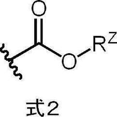
式2中、RZは、アルキル基を表し、波線は、上記式1-1中のLで表される基との結合部位を表す。
<16> 上記赤外線吸収剤の含有量が、上記画像記録層の全質量に対し、0.1質量%~10質量%である、<1>~<15>のいずれか1つに記載の平版印刷版原版。
<17> 上記重合性化合物のエチレン性不飽和結合当量が、200g/mol以下である、<1>~<16>のいずれか1つに記載の平版印刷版原版。
<18> 上記重合性化合物の重量平均分子量が、1,500以下である、<1>~<17>のいずれか1つに記載の平版印刷版原版。
<19> 上記重合性化合物が、3官能以上の重合性化合物を含む、<1>~<18>のいずれか1つに記載の平版印刷版原版。
<20> 上記重合性化合物が、7官能以上の重合性基を有する、<1>~<18>のいずれか1つに記載の平版印刷版原版。
<21> 上記重合性化合物が、10官能以上の重合性基を有する、<1>~<18>のいずれか1つに記載の平版印刷版原版。
<22> 上記画像記録層が、2種以上の重合性化合物を含む、<1>~<21>のいずれか1つに記載の平版印刷版原版。
<23> 上記画像記録層が、さらに酸発色剤を含む、<1>~<22>のいずれか1つに記載の平版印刷版原版。
<24> 上記画像記録層が、現像促進剤を更に含む、<1>~<23>のいずれか1つに記載の平版印刷版原版。
<25> 上記画像記録層が、感脂化剤を更に含む、<1>~<24>のいずれか1つに記載の平版印刷版原版。
<26> 上記支持体が画像記録層側の表面にマイクロポアを有し、
上記表面におけるマイクロポアの平均径が13nmを超え100nm以下である、<1>~<25>のいずれか1つに記載の平版印刷版原版。
<27> 上記支持体が画像記録層側の表面に陽極酸化被膜を有し、
上記陽極酸化皮膜が、上記画像記録層側の陽極酸化皮膜表面から深さ方向にのびる上記マイクロポアを有し、
上記マイクロポアが、上記陽極酸化皮膜表面から深さ10nm~1,000nmの位置までのびる大径孔部と、
上記大径孔部の底部と連通し、上記連通位置から深さ20nm~2,000nmの位置までのびる小径孔部と、から構成され、
上記大径孔部の平均径が、13nmを超え100nm以下であり、
上記小径孔部の平均径が、上記大径孔部の平均径の5%~80%である、<26>に記載の平版印刷版原版。
<28> <1>~<26>のいずれか1つに記載の平版印刷版原版を、画像様に露光する工程と、
印刷機上で印刷インキ及び湿し水よりなる群から選ばれた少なくとも一方を供給して非画像部の画像記録層を除去する工程と、を含む
平版印刷版の作製方法。
<29> <1>~<26>のいずれか1つに記載の平版印刷版原版を画像様に露光する工程と、
印刷機上で印刷インキ及び湿し水よりなる群から選ばれた少なくとも一方を供給して非画像部の画像記録層を除去し平版印刷版を作製する工程と、
得られた平版印刷版により印刷する工程と、を含む、
平版印刷方法。
<17> 上記重合性化合物のエチレン性不飽和結合当量が、200g/mol以下である、<1>~<16>のいずれか1つに記載の平版印刷版原版。
<18> 上記重合性化合物の重量平均分子量が、1,500以下である、<1>~<17>のいずれか1つに記載の平版印刷版原版。
<19> 上記重合性化合物が、3官能以上の重合性化合物を含む、<1>~<18>のいずれか1つに記載の平版印刷版原版。
<20> 上記重合性化合物が、7官能以上の重合性基を有する、<1>~<18>のいずれか1つに記載の平版印刷版原版。
<21> 上記重合性化合物が、10官能以上の重合性基を有する、<1>~<18>のいずれか1つに記載の平版印刷版原版。
<22> 上記画像記録層が、2種以上の重合性化合物を含む、<1>~<21>のいずれか1つに記載の平版印刷版原版。
<23> 上記画像記録層が、さらに酸発色剤を含む、<1>~<22>のいずれか1つに記載の平版印刷版原版。
<24> 上記画像記録層が、現像促進剤を更に含む、<1>~<23>のいずれか1つに記載の平版印刷版原版。
<25> 上記画像記録層が、感脂化剤を更に含む、<1>~<24>のいずれか1つに記載の平版印刷版原版。
<26> 上記支持体が画像記録層側の表面にマイクロポアを有し、
上記表面におけるマイクロポアの平均径が13nmを超え100nm以下である、<1>~<25>のいずれか1つに記載の平版印刷版原版。
<27> 上記支持体が画像記録層側の表面に陽極酸化被膜を有し、
上記陽極酸化皮膜が、上記画像記録層側の陽極酸化皮膜表面から深さ方向にのびる上記マイクロポアを有し、
上記マイクロポアが、上記陽極酸化皮膜表面から深さ10nm~1,000nmの位置までのびる大径孔部と、
上記大径孔部の底部と連通し、上記連通位置から深さ20nm~2,000nmの位置までのびる小径孔部と、から構成され、
上記大径孔部の平均径が、13nmを超え100nm以下であり、
上記小径孔部の平均径が、上記大径孔部の平均径の5%~80%である、<26>に記載の平版印刷版原版。
<28> <1>~<26>のいずれか1つに記載の平版印刷版原版を、画像様に露光する工程と、
印刷機上で印刷インキ及び湿し水よりなる群から選ばれた少なくとも一方を供給して非画像部の画像記録層を除去する工程と、を含む
平版印刷版の作製方法。
<29> <1>~<26>のいずれか1つに記載の平版印刷版原版を画像様に露光する工程と、
印刷機上で印刷インキ及び湿し水よりなる群から選ばれた少なくとも一方を供給して非画像部の画像記録層を除去し平版印刷版を作製する工程と、
得られた平版印刷版により印刷する工程と、を含む、
平版印刷方法。
本開示の一実施形態によれば、得られる平版印刷版において、UVインキを用いた場合であっても耐刷性に優れる平版印刷版原版を提供することができる。
また、本開示の他の実施形態によれば、上記平版印刷版原版を用いた平版印刷版の作製方法又は平版印刷版の印刷方法を提供することができる。
また、本開示の他の実施形態によれば、上記平版印刷版原版を用いた平版印刷版の作製方法又は平版印刷版の印刷方法を提供することができる。
以下において、本開示の内容について詳細に説明する。以下に記載する構成要件の説明は、本開示の代表的な実施態様に基づいてなされることがあるが、本開示はそのような実施態様に限定されるものではない。
なお、本明細書において、数値範囲を示す「~」とはその前後に記載される数値を下限値及び上限値として含む意味で使用される。
また、本明細書における基(原子団)の表記において、置換及び無置換を記していない表記は、置換基を有さないものと共に置換基を有するものをも包含するものである。例えば「アルキル基」とは、置換基を有さないアルキル基(無置換アルキル基)のみならず、置換基を有するアルキル基(置換アルキル基)をも包含するものである。
本明細書において、「(メタ)アクリル」は、アクリル及びメタクリルの両方を包含する概念で用いられる語であり、「(メタ)アクリロイル」は、アクリロイル及びメタクリロイルの両方を包含する概念として用いられる語である。
また、本明細書中の「工程」の用語は、独立した工程だけではなく、他の工程と明確に区別できない場合であっても、その工程の所期の目的が達成されれば本用語に含まれる。 また、本開示において、「質量%」と「重量%」とは同義であり、「質量部」と「重量部」とは同義である。
特に限定しない限りにおいて、本開示において組成物中の各成分、又は、ポリマー中の各構成単位は、1種単独で含まれていてもよいし、2種以上を併用してもよいものとする。
更に、本開示において組成物中の各成分、又は、ポリマー中の各構成単位の量は、組成物中に各成分、又は、ポリマー中の各構成単位に該当する物質又は構成単位が複数存在する場合、特に断らない限り、組成物中に存在する該当する複数の物質、又は、ポリマー中に存在する該当する複数の各構成単位の合計量を意味する。
更に、本開示において、2以上の好ましい態様の組み合わせは、より好ましい態様である。
また、本開示における重量平均分子量(Mw)及び数平均分子量(Mn)は、特に断りのない限り、TSKgel GMHxL、TSKgel G4000HxL、TSKgel G2000HxL(何れも東ソー(株)製の商品名)のカラムを使用したゲルパーミエーションクロマトグラフィ(GPC)分析装置により、溶媒THF(テトラヒドロフラン)、示差屈折計により検出し、標準物質としてポリスチレンを用いて換算した分子量である。
本開示において、「平版印刷版原版」の用語は、平版印刷版原版だけでなく、捨て版原版を包含する。また、「平版印刷版」の用語は、平版印刷版原版を、必要により、露光、現像などの操作を経て作製された平版印刷版だけでなく、捨て版を包含する。捨て版原版の場合には、必ずしも、露光、現像の操作は必要ない。なお、捨て版とは、例えばカラーの新聞印刷において一部の紙面を単色又は2色で印刷を行う場合に、使用しない版胴に取り付けるための平版印刷版原版である。
また、本開示において、化学構造式における「*」は、他の構造との結合位置を表す。
以下、本開示を詳細に説明する。
なお、本明細書において、数値範囲を示す「~」とはその前後に記載される数値を下限値及び上限値として含む意味で使用される。
また、本明細書における基(原子団)の表記において、置換及び無置換を記していない表記は、置換基を有さないものと共に置換基を有するものをも包含するものである。例えば「アルキル基」とは、置換基を有さないアルキル基(無置換アルキル基)のみならず、置換基を有するアルキル基(置換アルキル基)をも包含するものである。
本明細書において、「(メタ)アクリル」は、アクリル及びメタクリルの両方を包含する概念で用いられる語であり、「(メタ)アクリロイル」は、アクリロイル及びメタクリロイルの両方を包含する概念として用いられる語である。
また、本明細書中の「工程」の用語は、独立した工程だけではなく、他の工程と明確に区別できない場合であっても、その工程の所期の目的が達成されれば本用語に含まれる。 また、本開示において、「質量%」と「重量%」とは同義であり、「質量部」と「重量部」とは同義である。
特に限定しない限りにおいて、本開示において組成物中の各成分、又は、ポリマー中の各構成単位は、1種単独で含まれていてもよいし、2種以上を併用してもよいものとする。
更に、本開示において組成物中の各成分、又は、ポリマー中の各構成単位の量は、組成物中に各成分、又は、ポリマー中の各構成単位に該当する物質又は構成単位が複数存在する場合、特に断らない限り、組成物中に存在する該当する複数の物質、又は、ポリマー中に存在する該当する複数の各構成単位の合計量を意味する。
更に、本開示において、2以上の好ましい態様の組み合わせは、より好ましい態様である。
また、本開示における重量平均分子量(Mw)及び数平均分子量(Mn)は、特に断りのない限り、TSKgel GMHxL、TSKgel G4000HxL、TSKgel G2000HxL(何れも東ソー(株)製の商品名)のカラムを使用したゲルパーミエーションクロマトグラフィ(GPC)分析装置により、溶媒THF(テトラヒドロフラン)、示差屈折計により検出し、標準物質としてポリスチレンを用いて換算した分子量である。
本開示において、「平版印刷版原版」の用語は、平版印刷版原版だけでなく、捨て版原版を包含する。また、「平版印刷版」の用語は、平版印刷版原版を、必要により、露光、現像などの操作を経て作製された平版印刷版だけでなく、捨て版を包含する。捨て版原版の場合には、必ずしも、露光、現像の操作は必要ない。なお、捨て版とは、例えばカラーの新聞印刷において一部の紙面を単色又は2色で印刷を行う場合に、使用しない版胴に取り付けるための平版印刷版原版である。
また、本開示において、化学構造式における「*」は、他の構造との結合位置を表す。
以下、本開示を詳細に説明する。
(平版印刷版原版)
本開示に係る平版印刷版原版は、支持体上に画像記録層を有し、上記画像記録層が、赤外線吸収剤、重合開始剤、重合性化合物、及び、熱可塑性樹脂粒子を含む。
本開示に係る平版印刷版原版は、ネガ型平版印刷版原版であることが好ましい。
また、本開示に係る平版印刷版原版は、機上現像型平版印刷版原版であることが好ましい。
本開示に係る平版印刷版原版は、支持体上に画像記録層を有し、上記画像記録層が、赤外線吸収剤、重合開始剤、重合性化合物、及び、熱可塑性樹脂粒子を含む。
本開示に係る平版印刷版原版は、ネガ型平版印刷版原版であることが好ましい。
また、本開示に係る平版印刷版原版は、機上現像型平版印刷版原版であることが好ましい。
本発明者が鋭意検討した結果、得られる平版印刷版において、UVインキを用いた場合であっても耐刷性に優れる平版印刷版原版を提供することができることを見出した。
上記効果が得られる詳細なメカニズムは不明であるが、以下のように推測される。
上記効果が得られる詳細なメカニズムは不明であるが、以下のように推測される。
本開示に係る平版印刷版原版の画像記録層において、赤外線吸収剤と、重合開始剤と、重合性化合物と、熱可塑性樹脂粒子とを併用することによって、熱可塑性樹脂粒子同士の熱融着に加えて、熱可塑性樹脂粒子の熱融着物と混ざり合いながら重合性化合物が重合することにより、より強固な膜が形成されUVインクを用いた場合であっても耐刷性に優れると推定している。
平版印刷版において、版の印刷可能な枚数が多いことを、「耐刷性に優れる」という。UVインキを用いた場合の耐刷性を、以下、「UV耐刷性」ともいう。
平版印刷版において、版の印刷可能な枚数が多いことを、「耐刷性に優れる」という。UVインキを用いた場合の耐刷性を、以下、「UV耐刷性」ともいう。
更に、本開示に係る平版印刷版原版によれば、インキ着肉性(以下、単に「着肉性」ともいう。)に優れた平版印刷版が得られやすいと考えられる。これは、画像記録層において熱可塑性樹脂粒子を用いることにより画像部の疎水性の向上、熱可塑性樹脂粒子同士の熱融着に加えて、熱可塑性樹脂粒子の熱融着物と混ざり合いながら重合性化合物重合することにより、より強固な膜が形成されることによるUV耐刷性の相乗的な効果等によるものであると推測される。
本開示に係る平版印刷版原版の画像記録層において、赤外線吸収剤と、重合開始剤と、重合性化合物と、熱可塑性樹脂粒子とを併用することによって、強固な膜が形成されるため、耐薬品性にも優れやすいと推測される。
また、同様の理由から、経時保管後であっても機上現像性(以下、「経時機上現像性」ともいう。)にも優れやすいと推定される。
以下、本開示に係る平版印刷版原版における各構成要件の詳細について説明する。
また、同様の理由から、経時保管後であっても機上現像性(以下、「経時機上現像性」ともいう。)にも優れやすいと推定される。
以下、本開示に係る平版印刷版原版における各構成要件の詳細について説明する。
<画像記録層>
本開示に係る平版印刷版原版は、支持体上に形成された画像記録層を有する。
本開示における画像記録層は、赤外線吸収剤、重合開始剤、重合性化合物、及び、熱可塑性樹脂粒子を含む。
本開示に用いられる画像記録層は、ネガ型画像記録層であることが好ましく、水溶性又は水分散性のネガ型画像記録層であることがより好ましい。
本開示に係る平版印刷版原版は、機上現像性の観点から、画像記録層の未露光部が湿し水及び印刷インキの少なくともいずれかにより除去可能であることが好ましい。
以下、画像記録層に含まれる各成分の詳細について説明する。
本開示に係る平版印刷版原版は、支持体上に形成された画像記録層を有する。
本開示における画像記録層は、赤外線吸収剤、重合開始剤、重合性化合物、及び、熱可塑性樹脂粒子を含む。
本開示に用いられる画像記録層は、ネガ型画像記録層であることが好ましく、水溶性又は水分散性のネガ型画像記録層であることがより好ましい。
本開示に係る平版印刷版原版は、機上現像性の観点から、画像記録層の未露光部が湿し水及び印刷インキの少なくともいずれかにより除去可能であることが好ましい。
以下、画像記録層に含まれる各成分の詳細について説明する。
〔熱可塑性樹脂粒子〕
本開示において用いられる画像記録層は、熱可塑性樹脂粒子を含む。
熱可塑性樹脂粒子に含まれる熱可塑性樹脂は、特に制限はなく、例えば、ポリエチレン、ポリスチレン、ポリ塩化ビニル、ポリ塩化ビニリデン、ポリ(メタ)アクリル酸メチル、ポリ(メタ)アクリル酸エチル、ポリ(メタ)アクリル酸ブチル、ポリアクリロニトリル、ポリ酢酸ビニル、それらの共重合体等が挙げられる。熱可塑性樹脂はラテックス状態であってもよい。
本開示に係る熱可塑性樹脂は、後述する露光工程において生成された熱により、熱可塑性樹脂が溶融又は軟化することで、記録層を形成する疎水性の膜の一部又は全部を形成する樹脂であることが好ましい。
本開示において用いられる画像記録層は、熱可塑性樹脂粒子を含む。
熱可塑性樹脂粒子に含まれる熱可塑性樹脂は、特に制限はなく、例えば、ポリエチレン、ポリスチレン、ポリ塩化ビニル、ポリ塩化ビニリデン、ポリ(メタ)アクリル酸メチル、ポリ(メタ)アクリル酸エチル、ポリ(メタ)アクリル酸ブチル、ポリアクリロニトリル、ポリ酢酸ビニル、それらの共重合体等が挙げられる。熱可塑性樹脂はラテックス状態であってもよい。
本開示に係る熱可塑性樹脂は、後述する露光工程において生成された熱により、熱可塑性樹脂が溶融又は軟化することで、記録層を形成する疎水性の膜の一部又は全部を形成する樹脂であることが好ましい。
上記熱可塑性樹脂としては、インキ着肉性及びUV耐刷性の観点から、芳香族ビニル化合物により形成される構成単位、及び、シアノ基を有する構成単位を有する樹脂A含むことが好ましい。
-芳香族ビニル化合物により形成される構成単位-
熱可塑性樹脂に含まれる樹脂Aは、芳香族ビニル化合物により形成される構成単位を有することが好ましい。
芳香族ビニル化合物としては、芳香環にビニル基が結合した構造を有する化合物であればよいが、スチレン化合物、ビニルナフタレン化合物等が挙げられ、スチレン化合物が好ましく、スチレンがより好ましい。
スチレン化合物としては、スチレン、p-メチルスチレン、p-メトキシスチレン、β-メチルスチレン、p-メチル-β-メチルスチレン、α-メチルスチレン、及びp-メトキシ-β-メチルスチレン等が挙げられ、スチレンが好ましく挙げられる。
ビニルナフタレン化合物としては、1-ビニルナフタレン、メチル-1-ビニルナフタレン、β-メチル-1-ビニルナフタレン、4-メチル-1-ビニルナフタレン、4-メトキシ-1-ビニルナフタレン等が挙げられ、1-ビニルナフタレンが好ましく挙げられる。
熱可塑性樹脂に含まれる樹脂Aは、芳香族ビニル化合物により形成される構成単位を有することが好ましい。
芳香族ビニル化合物としては、芳香環にビニル基が結合した構造を有する化合物であればよいが、スチレン化合物、ビニルナフタレン化合物等が挙げられ、スチレン化合物が好ましく、スチレンがより好ましい。
スチレン化合物としては、スチレン、p-メチルスチレン、p-メトキシスチレン、β-メチルスチレン、p-メチル-β-メチルスチレン、α-メチルスチレン、及びp-メトキシ-β-メチルスチレン等が挙げられ、スチレンが好ましく挙げられる。
ビニルナフタレン化合物としては、1-ビニルナフタレン、メチル-1-ビニルナフタレン、β-メチル-1-ビニルナフタレン、4-メチル-1-ビニルナフタレン、4-メトキシ-1-ビニルナフタレン等が挙げられ、1-ビニルナフタレンが好ましく挙げられる。
また、芳香族ビニル化合物により形成される構成単位としては、下記式A1で表される構成単位が好ましく挙げられる。
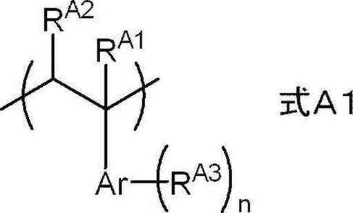
式A1中、RA1及びRA2はそれぞれ独立に、水素原子又はアルキル基を表し、Arは芳香環基を表し、RA3は置換基を表し、nは0以上Arの最大置換基数以下の整数を表す。
式A1中、RA1及びRA2はそれぞれ独立に、水素原子又は炭素数1~4のアルキル基であることが好ましく、水素原子又はメチル基であることがより好ましく、いずれも水素原子であることが更に好ましい。
式A1中、Arはベンゼン環又はナフタレン環であることが好ましく、ベンゼン環であることがより好ましい。
式A1中、RA3はアルキル基又はアルコキシ基であることが好ましく、炭素数1~4のアルキル基又は炭素数1~4のアルコキシ基であることがより好ましく、メチル基又はメトキシ基であることが更に好ましい。
式A1中、RA3が複数存在する場合、複数のRA3は同一であってもよいし、それぞれ異なっていてもよい。
式A1中、nは0~2の整数であることが好ましく、0又は1であることがより好ましく、0であることが更に好ましい。
式A1中、RA1及びRA2はそれぞれ独立に、水素原子又は炭素数1~4のアルキル基であることが好ましく、水素原子又はメチル基であることがより好ましく、いずれも水素原子であることが更に好ましい。
式A1中、Arはベンゼン環又はナフタレン環であることが好ましく、ベンゼン環であることがより好ましい。
式A1中、RA3はアルキル基又はアルコキシ基であることが好ましく、炭素数1~4のアルキル基又は炭素数1~4のアルコキシ基であることがより好ましく、メチル基又はメトキシ基であることが更に好ましい。
式A1中、RA3が複数存在する場合、複数のRA3は同一であってもよいし、それぞれ異なっていてもよい。
式A1中、nは0~2の整数であることが好ましく、0又は1であることがより好ましく、0であることが更に好ましい。
熱可塑性樹脂に含まれる樹脂Aにおいて、芳香族ビニル化合物により形成される構成単位の含有量は、インキ着肉性の観点から、後述するシアノ基を有する構成単位の含有量よりも多いことが好ましく、熱可塑性樹脂の全質量に対し、15質量%~85質量%であることがより好ましく、30質量%~70質量%であることが更に好ましい。
-シアノ基を有する構成単位-
熱可塑性樹脂粒子に含まれる樹脂Aは、シアノ基を有する構成単位を含むことが好ましい。
シアノ基は、通常、シアノ基を有する化合物(モノマー)を用いて、シアノ基を含む構成単位として樹脂Aに導入されることが好ましい。シアノ基を有する化合物としては、アクリロニトリル化合物が挙げられ、(メタ)アクリロニトリルが好適に挙げられる。
シアノ基を有する構成単位としては、アクリロニトリル化合物により形成される構成単位であることが好ましく、(メタ)アクリロニトリルにより形成される構成単位がより好ましい。
熱可塑性樹脂粒子に含まれる樹脂Aは、シアノ基を有する構成単位を含むことが好ましい。
シアノ基は、通常、シアノ基を有する化合物(モノマー)を用いて、シアノ基を含む構成単位として樹脂Aに導入されることが好ましい。シアノ基を有する化合物としては、アクリロニトリル化合物が挙げられ、(メタ)アクリロニトリルが好適に挙げられる。
シアノ基を有する構成単位としては、アクリロニトリル化合物により形成される構成単位であることが好ましく、(メタ)アクリロニトリルにより形成される構成単位がより好ましい。
また、シアノ基を有する化合物により形成される構成単位としては、下記式B1で表される構成単位が好ましく挙げられる。

式B1中、RB1は水素原子又はアルキル基を表す。
式B1中、RB1は水素原子又は炭素数1~4のアルキル基であることが好ましく、水素原子又はメチル基であることがより好ましく、水素原子であることが更に好ましい。
式B1中、RB1は水素原子又は炭素数1~4のアルキル基であることが好ましく、水素原子又はメチル基であることがより好ましく、水素原子であることが更に好ましい。
樹脂Aにおけるシアノ基を有する構成単位の含有量は、インキ着肉性の観点から、上記芳香族ビニル化合物により形成されるよりも少ないことが好ましく、樹脂Aの全質量に対し、55質量%~90質量%であることがより好ましく、60質量%~85質量%であることがより好ましい。
また、熱可塑性樹脂に含まれる樹脂Aが芳香族ビニル化合物により形成される構成単位及びシアノ基を有する構成単位を含む場合、芳香族ビニル化合物により形成される構成単位及びシアノ基を有する構成単位の含有量比(芳香族ビニル化合物により形成される構成単位:シアノ基を有する構成単位)としては、質量基準で5:5~9:1であることが好ましく、より好ましくは、6:4~8:2である。
-N-ビニル複素環化合物により形成される構成単位-
熱可塑性樹脂粒子に含まれる樹脂Aは、UV耐刷性及び耐薬品性の観点から、N-ビニル複素環化合物により形成される構成単位を更に有することが好ましい。
N-ビニル複素環化合物としては、例えば、N-ビニルピロリドン、N-ビニルカルバゾール、N-ビニルピロール、N-ビニルフェノチアジン、N-ビニルコハク酸イミド、N-ビニルフタルイミド、N-ビニルカプロラクタム、及びN-ビニルイミダゾールが挙げられ、N-ビニルピロリドンが好ましい。
熱可塑性樹脂粒子に含まれる樹脂Aは、UV耐刷性及び耐薬品性の観点から、N-ビニル複素環化合物により形成される構成単位を更に有することが好ましい。
N-ビニル複素環化合物としては、例えば、N-ビニルピロリドン、N-ビニルカルバゾール、N-ビニルピロール、N-ビニルフェノチアジン、N-ビニルコハク酸イミド、N-ビニルフタルイミド、N-ビニルカプロラクタム、及びN-ビニルイミダゾールが挙げられ、N-ビニルピロリドンが好ましい。
また、N-ビニル複素環化合物により形成される構成単位としては、下記式C1で表される構成単位が好ましく挙げられる。

式C1中、ArNは窒素原子を含む複素環構造を表し、ArN中の窒素原子が*で示した炭素原子と結合する。
式C1中、ArNにより表される複素環構造は、ピロリドン環、カルバゾール環、ピロール環、フェノチアジン環、スクシンイミド環、フタルイミド環、カプロラクタム環、及びイミダゾール環であることが好ましく、ピロリドン環であることがより好ましい。
また、ArNにより表される複素環構造は公知の置換基を有していてもよい。
式C1中、ArNにより表される複素環構造は、ピロリドン環、カルバゾール環、ピロール環、フェノチアジン環、スクシンイミド環、フタルイミド環、カプロラクタム環、及びイミダゾール環であることが好ましく、ピロリドン環であることがより好ましい。
また、ArNにより表される複素環構造は公知の置換基を有していてもよい。
樹脂Aにおける、N-ビニル複素環化合物により形成される構成単位の含有量は、樹脂Aの全質量に対し、5質量%~50質量%であることが好ましく、10質量%~40質量%であることがより好ましい。
-酸性基を有する構成単位-
熱可塑性樹脂粒子に含まれる樹脂Aは、酸性基を有する構成単位を含有してもよいが、機上現像性及びインキ着肉性の観点からは、酸性基を有する構成単位を含有しないことが好ましい。
具体的には、熱可塑性樹脂における酸性基を有する構成単位の含有量は、20質量%以下であることが好ましく、10質量%以下であることがより好ましく、5質量%以下であることが更に好ましい。上記含有量の下限は特に限定されず、0質量%であってもよい。
また、熱可塑性樹脂の酸価は、160mgKOH/g以下であることが好ましく、80mgKOH/g以下であることがより好ましく、40mgKOH/g以下であることが更に好ましい。上記酸価の下限は特に限定されず、0mgKOH/gであってもよい。
本開示において、酸価はJIS K0070:1992に準拠した測定法により求められる。
熱可塑性樹脂粒子に含まれる樹脂Aは、酸性基を有する構成単位を含有してもよいが、機上現像性及びインキ着肉性の観点からは、酸性基を有する構成単位を含有しないことが好ましい。
具体的には、熱可塑性樹脂における酸性基を有する構成単位の含有量は、20質量%以下であることが好ましく、10質量%以下であることがより好ましく、5質量%以下であることが更に好ましい。上記含有量の下限は特に限定されず、0質量%であってもよい。
また、熱可塑性樹脂の酸価は、160mgKOH/g以下であることが好ましく、80mgKOH/g以下であることがより好ましく、40mgKOH/g以下であることが更に好ましい。上記酸価の下限は特に限定されず、0mgKOH/gであってもよい。
本開示において、酸価はJIS K0070:1992に準拠した測定法により求められる。
-疎水性基を有する構成単位-
熱可塑性樹脂粒子に含まれる樹脂Aは、インキ着肉性の観点から、疎水性基を含む構成単位を含有してもよい。
上記疎水性基としては、アルキル基、アリール基、アラルキル基等が挙げられる。
疎水性基を含む構成単位としては、アルキル(メタ)アクリレート化合物、アリール(メタ)アクリレート化合物、又は、アラルキル(メタ)アクリレート化合物により形成される構成単位が好ましく、アルキル(メタ)アクリレート化合物により形成される構成単位がより好ましい。
上記アルキル(メタ)アクリレート化合物におけるアルキル基の炭素数は、1~10であることが好ましい。上記アルキル基は直鎖状であっても分岐鎖状であってもよく、環状構造を有していてもよい。アルキル(メタ)アクリレート化合物としては、メチル(メタ)アクリレート、エチル(メタ)アクリレート、プロピル(メタ)アクリレート、シクロヘキシル(メタ)アクリレート、2-エチルヘキシル(メタ)アクリレート、ジシクロペンタニル(メタ)アクリレート等が挙げられる。
上記アリール(メタ)アクリレート化合物におけるアリール基の炭素数は、6~20であることが好ましく、フェニル基であることがより好ましい。また、上記アリール基は公知の置換基を有していてもよい。アリール(メタ)アクリレート化合物としては、フェニル(メタ)アクリレートが好ましく挙げられる。
上記アラルキル(メタ)アクリレート化合物におけるアルキル基の炭素数は、1~10であることが好ましい。上記アルキル基は直鎖状であっても分岐鎖状であってもよく、環状構造を有していてもよい。また、上記アラルキル(メタ)アクリレート化合物におけるアリール基の炭素数は、6~20であることが好ましく、フェニル基であることがより好ましい。アラルキル(メタ)アクリレート化合物としては、ベンジル(メタ)アクリレートが好ましく挙げられる。
熱可塑性樹脂粒子に含まれる樹脂Aは、インキ着肉性の観点から、疎水性基を含む構成単位を含有してもよい。
上記疎水性基としては、アルキル基、アリール基、アラルキル基等が挙げられる。
疎水性基を含む構成単位としては、アルキル(メタ)アクリレート化合物、アリール(メタ)アクリレート化合物、又は、アラルキル(メタ)アクリレート化合物により形成される構成単位が好ましく、アルキル(メタ)アクリレート化合物により形成される構成単位がより好ましい。
上記アルキル(メタ)アクリレート化合物におけるアルキル基の炭素数は、1~10であることが好ましい。上記アルキル基は直鎖状であっても分岐鎖状であってもよく、環状構造を有していてもよい。アルキル(メタ)アクリレート化合物としては、メチル(メタ)アクリレート、エチル(メタ)アクリレート、プロピル(メタ)アクリレート、シクロヘキシル(メタ)アクリレート、2-エチルヘキシル(メタ)アクリレート、ジシクロペンタニル(メタ)アクリレート等が挙げられる。
上記アリール(メタ)アクリレート化合物におけるアリール基の炭素数は、6~20であることが好ましく、フェニル基であることがより好ましい。また、上記アリール基は公知の置換基を有していてもよい。アリール(メタ)アクリレート化合物としては、フェニル(メタ)アクリレートが好ましく挙げられる。
上記アラルキル(メタ)アクリレート化合物におけるアルキル基の炭素数は、1~10であることが好ましい。上記アルキル基は直鎖状であっても分岐鎖状であってもよく、環状構造を有していてもよい。また、上記アラルキル(メタ)アクリレート化合物におけるアリール基の炭素数は、6~20であることが好ましく、フェニル基であることがより好ましい。アラルキル(メタ)アクリレート化合物としては、ベンジル(メタ)アクリレートが好ましく挙げられる。
熱可塑性樹脂粒子に含まれる樹脂Aにおける、疎水性基を有する構成単位の含有量は、樹脂Aの全質量に対し、5質量%~50質量%であることが好ましく、10質量%~30質量%であることがより好ましい。
上記熱可塑性樹脂粒子に含まれる熱可塑性樹脂は、UV耐刷性及び機上現像性の観点から、親水性基を有することが好ましい。
親水性基としては、親水性を有する構造であれば、特に制限はないが、カルボキシ基等の酸基、ヒドロキシ基、アミノ基、シアノ基、ポリアルキレンオキシド構造等が挙げられる。
上記親水性基としては、UV耐刷性及び機上現像性の観点から、ポリアルキレンオキシド構造を有する基、ポリエステル構造を有する基、又は、スルホン酸基であることが好ましく、ポリアルキレンオキシド構造を有する基、又は、スルホン酸基であることがより好ましく、ポリアルキレンオキシド構造を有する基であることが更に好ましい。
親水性基としては、親水性を有する構造であれば、特に制限はないが、カルボキシ基等の酸基、ヒドロキシ基、アミノ基、シアノ基、ポリアルキレンオキシド構造等が挙げられる。
上記親水性基としては、UV耐刷性及び機上現像性の観点から、ポリアルキレンオキシド構造を有する基、ポリエステル構造を有する基、又は、スルホン酸基であることが好ましく、ポリアルキレンオキシド構造を有する基、又は、スルホン酸基であることがより好ましく、ポリアルキレンオキシド構造を有する基であることが更に好ましい。
上記ポリアルキレンオキシド構造としては、機上現像性の観点から、ポリエチレンオキシド構造、ポリプロピレンオキシド構造、又は、ポリ(エチレンオキシド/プロピレンオキシド)構造であることが好ましい。
また、機上現像性の観点からは、上記親水性基の中でもポリアルキレンオキシド構造として、ポリプロピレンオキシド構造を有することが好ましく、ポリエチレンオキシド構造及びポリプロピレンオキシド構造を有することがより好ましい。
上記ポリアルキレンオキシド構造におけるアルキレンオキシド構造の数は、機上現像性の観点から、2以上であることが好ましく、5以上であることがより好ましく、5~200であることが更に好ましく、8~150であることが特に好ましい。
また、機上現像性の観点からは、上記親水性基の中でもポリアルキレンオキシド構造として、ポリプロピレンオキシド構造を有することが好ましく、ポリエチレンオキシド構造及びポリプロピレンオキシド構造を有することがより好ましい。
上記ポリアルキレンオキシド構造におけるアルキレンオキシド構造の数は、機上現像性の観点から、2以上であることが好ましく、5以上であることがより好ましく、5~200であることが更に好ましく、8~150であることが特に好ましい。
また、機上現像性の観点から、上記親水性基として、下記式Zで表される基が好ましく、下記式Zで表される基がより好ましい。
-Q-W-Y 式Z
式Z中、Qは二価の連結基を表し、Wは親水性構造を有する二価の基又は疎水性構造を有する二価の基を表し、Yは親水性構造を有する一価の基又は疎水性構造を有する一価の基を表し、ただし、W及びYのいずれかは親水性構造を有する。
-Q-W-Y 式Z
式Z中、Qは二価の連結基を表し、Wは親水性構造を有する二価の基又は疎水性構造を有する二価の基を表し、Yは親水性構造を有する一価の基又は疎水性構造を有する一価の基を表し、ただし、W及びYのいずれかは親水性構造を有する。
Qは、炭素数1~20の二価の連結基であることが好ましく、炭素数1~10の2価の連結基であることがより好ましい。
また、Qは、アルキレン基、アリーレン基、エステル結合、アミド結合、又は、これらを2以上組み合わせた基であることが好ましく、フェニレン基、エステル結合、又は、アミド結合であることがより好ましい。
また、Qは、アルキレン基、アリーレン基、エステル結合、アミド結合、又は、これらを2以上組み合わせた基であることが好ましく、フェニレン基、エステル結合、又は、アミド結合であることがより好ましい。
Wにおける親水性構造を有する二価の基は、ポリアルキレンオキシ基、又は、ポリアルキレンオキシ基の一方の末端に-CH2CH2NRW-が結合した基であることが好ましい。なお、RWは、水素原子又はアルキル基を表す。
Wにおける疎水性構造を有する二価の基は、-RWA-、-O-RWA-O-、-RWN-RWA-NRW-、-OOC-RWA-O-、又は、-OOC-RWA-O-であることが好ましい。なお、RWAはそれぞれ独立に、炭素数6~120の直鎖、分岐若しくは環状アルキレン基、炭素数6~120のハロアルキレン基、炭素数6~120のアリーレン基、炭素数6~120のアルカーリレン基(アルキルアリール基から水素原子を1つ除いた二価の基)、又は、炭素数6~120のアラルキレン基を表す。
Wにおける疎水性構造を有する二価の基は、-RWA-、-O-RWA-O-、-RWN-RWA-NRW-、-OOC-RWA-O-、又は、-OOC-RWA-O-であることが好ましい。なお、RWAはそれぞれ独立に、炭素数6~120の直鎖、分岐若しくは環状アルキレン基、炭素数6~120のハロアルキレン基、炭素数6~120のアリーレン基、炭素数6~120のアルカーリレン基(アルキルアリール基から水素原子を1つ除いた二価の基)、又は、炭素数6~120のアラルキレン基を表す。
上記式ZのYにおける親水性構造を有する一価の基は、OH、COOH、末端が水素原子又はアルキル基であるポリアルキレンオキシ基、又は、末端が水素原子又はアルキル基であるポリアルキレンオキシ基の他方の末端に-CH2CH2N(RW)-が結合した基であることが好ましい。
上記式ZのYにおける疎水性構造を有する一価の基は、炭素数6~120の直鎖、分岐若しくは環状アルキル基、炭素数6~120のハロアルキル基、炭素数6~120のアリール基、炭素数6~120のアルカーリル基(アルキルアリール基)、炭素数6~120のアラルキル基、ORWB、COORWB、又は、OOCRWBであることが好ましい。なお、RWBは、炭素数6~20を有するアルキル基を表す。
上記式ZのYにおける疎水性構造を有する一価の基は、炭素数6~120の直鎖、分岐若しくは環状アルキル基、炭素数6~120のハロアルキル基、炭素数6~120のアリール基、炭素数6~120のアルカーリル基(アルキルアリール基)、炭素数6~120のアラルキル基、ORWB、COORWB、又は、OOCRWBであることが好ましい。なお、RWBは、炭素数6~20を有するアルキル基を表す。
上記式Zで表される基は、UV耐刷性、及び、機上現像性の観点から、Wが親水性構造を有する二価の基であることがより好ましく、Qがフェニレン基、エステル結合、又は、アミド結合であり、Wは、ポリアルキレンオキシ基であり、Yが、末端が水素原子又はアルキル基であるポリアルキレンオキシ基であることがより好ましい。
-親水性基を有する構成単位-
熱可塑性樹脂粒子に含まれる樹脂Aは、UV耐刷性、耐薬品性及び機上現像性の向上の観点から、親水性基を有する構成単位を含むことが好ましい。
上記親水性基としては、-OH、-CN、-CONR1R2、-NR2COR1(R1及びR2はそれぞれ独立して水素原子、アルキル基、アルケニル基、又は、アリール基を表す。R1とR2とは結合して環を形成してもよい。)-NR3R4、-N+R3R4R5X-(R3~R5は、それぞれ独立して炭素数1~8のアルキル基を表し、X-はカウンターアニオンを表す)、下記式POにより表される基、上記の熱可塑性樹脂粒子に含まれる熱可塑性樹脂が好ましく有する親水性基等が挙げられる。
これら親水性基の中でも、-CONR1R2又は式POにより表される基が好ましく、式POにより表される基がより好ましい。
熱可塑性樹脂粒子に含まれる樹脂Aは、UV耐刷性、耐薬品性及び機上現像性の向上の観点から、親水性基を有する構成単位を含むことが好ましい。
上記親水性基としては、-OH、-CN、-CONR1R2、-NR2COR1(R1及びR2はそれぞれ独立して水素原子、アルキル基、アルケニル基、又は、アリール基を表す。R1とR2とは結合して環を形成してもよい。)-NR3R4、-N+R3R4R5X-(R3~R5は、それぞれ独立して炭素数1~8のアルキル基を表し、X-はカウンターアニオンを表す)、下記式POにより表される基、上記の熱可塑性樹脂粒子に含まれる熱可塑性樹脂が好ましく有する親水性基等が挙げられる。
これら親水性基の中でも、-CONR1R2又は式POにより表される基が好ましく、式POにより表される基がより好ましい。

式PO中、LPはそれぞれ独立に、アルキレン基を表し、RPは水素原子又はアルキル基を表し、nは1~100の整数を表す。
式PO中、LPはそれぞれ独立に、エチレン基、1-メチルエチレン基又は2-メチルエチレン基であることが好ましく、エチレン基であることがより好ましい。
式PO中、RPは水素原子又は炭素数1~18のアルキル基であることが好ましく、水素原子又は炭素数1~10のアルキル基であることがより好ましく、水素原子又は炭素数1~4のアルキル基であることが更に好ましく、水素原子又はメチル基であることが特に好ましい。
式PO中、nは1~10の整数が好ましく、1~4の整数がより好ましい。
式PO中、LPはそれぞれ独立に、エチレン基、1-メチルエチレン基又は2-メチルエチレン基であることが好ましく、エチレン基であることがより好ましい。
式PO中、RPは水素原子又は炭素数1~18のアルキル基であることが好ましく、水素原子又は炭素数1~10のアルキル基であることがより好ましく、水素原子又は炭素数1~4のアルキル基であることが更に好ましく、水素原子又はメチル基であることが特に好ましい。
式PO中、nは1~10の整数が好ましく、1~4の整数がより好ましい。
樹脂Aにおける、親水性基を有する構成単位の含有量は、樹脂Aの全質量に対し、5質量%~60質量%であることが好ましく、10質量%~30質量%であることがより好ましい。
-その他の構成単位-
熱可塑性樹脂粒子に含まれる樹脂Aは、その他の構成単位を更に含有してもよい。その他の構成単位としては、上述の各構成単位以外の構成単位を特に限定なく含有することができ、例えば、アクリルアミド化合物、ビニルエーテル化合物等により形成される構成単位が挙げられる。
アクリルアミド化合物としては、例えば、(メタ)アクリルアミド、N-メチル(メタ)アクリルアミド、N-エチル(メタ)アクリルアミド、N-プロピル(メタ)アクリルアミド、N-ブチル(メタ)アクリルアミド、N,N’-ジメチル(メタ)アクリルアミド、N,N’-ジエチル(メタ)アクリルアミド、N-ヒドロキシエチル(メタ)アクリルアミド、N-ヒドロキシプロピル(メタ)アクリルアミド、N-ヒドロキシブチル(メタ)アクリルアミド等が挙げられる。
ビニルエーテル化合物としては、例えば、メチルビニルエーテル、エチルビニルエーテル、プロピルビニルエーテル、n-ブチルビニルエーテル、tert-ブチルビニルエーテル、2-エチルヘキシルビニルエーテル、n-ノニルビニルエーテル、ラウリルビニルエーテル、シクロヘキシルビニルエーテル、シクロヘキシルメチルビニルエーテル、4-メチルシクロヘキシルメチルビニルエーテル、ベンジルビニルエーテル、ジシクロペンテニルビニルエーテル、2-ジシクロペンテノキシエチルビニルエーテル、メトキシエチルビニルエーテル、エトキシエチルビニルエーテル、ブトキシエチルビニルエーテル、メトキシエトキシエチルビニルエーテル、エトキシエトキシエチルビニルエーテル、メトキシポリエチレングリコールビニルエーテル、テトラヒドロフルフリルビニルエーテル、2-ヒドロキシエチルビニルエーテル、2-ヒドロキシプロピルビニルエーテル、4-ヒドロキシブチルビニルエーテル、4-ヒドロキシメチルシクロヘキシルメチルビニルエーテル、ジエチレングリコールモノビニルエーテル、ポリエチレングリコールビニルエーテル、クロロエチルビニルエーテル、クロロブチルビニルエーテル、クロロエトキシエチルビニルエーテル、フェニルエチルビニルエーテル、フェノキシポリエチレングリコールビニルエーテル、などが挙げられる。
熱可塑性樹脂粒子に含まれる樹脂Aは、その他の構成単位を更に含有してもよい。その他の構成単位としては、上述の各構成単位以外の構成単位を特に限定なく含有することができ、例えば、アクリルアミド化合物、ビニルエーテル化合物等により形成される構成単位が挙げられる。
アクリルアミド化合物としては、例えば、(メタ)アクリルアミド、N-メチル(メタ)アクリルアミド、N-エチル(メタ)アクリルアミド、N-プロピル(メタ)アクリルアミド、N-ブチル(メタ)アクリルアミド、N,N’-ジメチル(メタ)アクリルアミド、N,N’-ジエチル(メタ)アクリルアミド、N-ヒドロキシエチル(メタ)アクリルアミド、N-ヒドロキシプロピル(メタ)アクリルアミド、N-ヒドロキシブチル(メタ)アクリルアミド等が挙げられる。
ビニルエーテル化合物としては、例えば、メチルビニルエーテル、エチルビニルエーテル、プロピルビニルエーテル、n-ブチルビニルエーテル、tert-ブチルビニルエーテル、2-エチルヘキシルビニルエーテル、n-ノニルビニルエーテル、ラウリルビニルエーテル、シクロヘキシルビニルエーテル、シクロヘキシルメチルビニルエーテル、4-メチルシクロヘキシルメチルビニルエーテル、ベンジルビニルエーテル、ジシクロペンテニルビニルエーテル、2-ジシクロペンテノキシエチルビニルエーテル、メトキシエチルビニルエーテル、エトキシエチルビニルエーテル、ブトキシエチルビニルエーテル、メトキシエトキシエチルビニルエーテル、エトキシエトキシエチルビニルエーテル、メトキシポリエチレングリコールビニルエーテル、テトラヒドロフルフリルビニルエーテル、2-ヒドロキシエチルビニルエーテル、2-ヒドロキシプロピルビニルエーテル、4-ヒドロキシブチルビニルエーテル、4-ヒドロキシメチルシクロヘキシルメチルビニルエーテル、ジエチレングリコールモノビニルエーテル、ポリエチレングリコールビニルエーテル、クロロエチルビニルエーテル、クロロブチルビニルエーテル、クロロエトキシエチルビニルエーテル、フェニルエチルビニルエーテル、フェノキシポリエチレングリコールビニルエーテル、などが挙げられる。
熱可塑性樹脂における、その他の構成単位の含有量は、熱可塑性樹脂の全質量に対し、5質量%~50質量%であることが好ましく、10質量%~30質量%であることがより好ましい。
-熱可塑性樹脂粒子に含まれる熱可塑性樹脂のガラス転移温度-
熱可塑性樹脂のガラス転移温度(Tg)は、UV耐刷性及びインキ着肉性の観点から、60℃~150℃であることが好ましく、80℃~140℃であることがより好ましく、90℃~130℃であることが更に好ましい。
熱可塑性樹脂粒子が2種以上の熱可塑性樹脂を含む場合には、後述するFOX式により求められた値を、熱可塑性樹脂のガラス転移温度という。
熱可塑性樹脂のガラス転移温度(Tg)は、UV耐刷性及びインキ着肉性の観点から、60℃~150℃であることが好ましく、80℃~140℃であることがより好ましく、90℃~130℃であることが更に好ましい。
熱可塑性樹脂粒子が2種以上の熱可塑性樹脂を含む場合には、後述するFOX式により求められた値を、熱可塑性樹脂のガラス転移温度という。
本開示において、樹脂のガラス転移温度は、示差走査熱量測定(DSC)を用いて測定することができる。
具体的な測定方法は、JIS K 7121(1987年)又はJIS K 6240(2011年)に記載の方法に順じて行なう。本明細書におけるガラス転移温度は、補外ガラス転移開始温度(以下、Tigと称することがある)を用いている。
ガラス転移温度の測定方法をより具体的に説明する。
ガラス転移温度を求める場合、予想される樹脂のTgより約50℃低い温度にて装置が安定するまで保持した後、加熱速度:20℃/分で、ガラス転移が終了した温度よりも約30℃高い温度まで加熱し,示差熱分析(DTA)曲線又はDSC曲線を作成する。
補外ガラス転移開始温度(Tig)、すなわち、本明細書におけるガラス転移温度Tgは、DTA曲線又はDSC曲線における低温側のベースラインを高温側に延長した直線と、ガラス転移の階段状変化部分の曲線の勾配が最大になる点で引いた接線との交点の温度として求める。
具体的な測定方法は、JIS K 7121(1987年)又はJIS K 6240(2011年)に記載の方法に順じて行なう。本明細書におけるガラス転移温度は、補外ガラス転移開始温度(以下、Tigと称することがある)を用いている。
ガラス転移温度の測定方法をより具体的に説明する。
ガラス転移温度を求める場合、予想される樹脂のTgより約50℃低い温度にて装置が安定するまで保持した後、加熱速度:20℃/分で、ガラス転移が終了した温度よりも約30℃高い温度まで加熱し,示差熱分析(DTA)曲線又はDSC曲線を作成する。
補外ガラス転移開始温度(Tig)、すなわち、本明細書におけるガラス転移温度Tgは、DTA曲線又はDSC曲線における低温側のベースラインを高温側に延長した直線と、ガラス転移の階段状変化部分の曲線の勾配が最大になる点で引いた接線との交点の温度として求める。
熱可塑性樹脂粒子が2種以上の熱可塑性樹脂を含む場合、熱可塑性樹脂粒子に含まれる熱可塑性樹脂のTgは下記のように求められる。
1つ目の熱可塑性樹脂のTgをTg1(K)、熱可塑性樹脂粒子における熱可塑性樹脂成分の合計質量に対する1つ目の熱可塑性樹脂の質量分率をW1とし、2つ目のTgをTg2(K)とし、熱可塑性樹脂粒子における熱可塑性樹脂成分の合計質量に対する2つ目の樹脂の質量分率をW2としたときに、熱可塑性樹脂粒子のTg0(K)は、以下のFOX式にしたがって推定することが可能である。
FOX式:1/Tg0=(W1/Tg1)+(W2/Tg2)
また、熱可塑性樹脂粒子が3種の樹脂を含むか、含まれる熱可塑性樹脂種の異なる3種の熱可塑性樹脂粒子が前処理液に含有される場合、熱可塑性樹脂粒子のTgは、n個目の樹脂のTgをTgn(K)、熱可塑性樹脂粒子における樹脂成分の合計質量に対するn個目の樹脂の質量分率をWnとしたときに、上記と同様、以下の式にしたがって推定することが可能である。
FOX式:1/Tg0=(W1/Tg1)+(W2/Tg2)+(W3/Tg3)・・・+(Wn/Tgn)
1つ目の熱可塑性樹脂のTgをTg1(K)、熱可塑性樹脂粒子における熱可塑性樹脂成分の合計質量に対する1つ目の熱可塑性樹脂の質量分率をW1とし、2つ目のTgをTg2(K)とし、熱可塑性樹脂粒子における熱可塑性樹脂成分の合計質量に対する2つ目の樹脂の質量分率をW2としたときに、熱可塑性樹脂粒子のTg0(K)は、以下のFOX式にしたがって推定することが可能である。
FOX式:1/Tg0=(W1/Tg1)+(W2/Tg2)
また、熱可塑性樹脂粒子が3種の樹脂を含むか、含まれる熱可塑性樹脂種の異なる3種の熱可塑性樹脂粒子が前処理液に含有される場合、熱可塑性樹脂粒子のTgは、n個目の樹脂のTgをTgn(K)、熱可塑性樹脂粒子における樹脂成分の合計質量に対するn個目の樹脂の質量分率をWnとしたときに、上記と同様、以下の式にしたがって推定することが可能である。
FOX式:1/Tg0=(W1/Tg1)+(W2/Tg2)+(W3/Tg3)・・・+(Wn/Tgn)
本明細書において、Tgは、示差走査熱量計(DSC:Differential scanning calorimetry)により測定される値である。示差走査熱量計(DSC)としては、例えば、エスアイアイ・ナノテクノロジー社のEXSTAR6220を用いることができる。
-粒子径-
熱可塑性樹脂粒子の算術平均粒子径は、UV耐刷性の観点から、1nm以上200nm以下であることが好ましく、3nm以上80nm未満であることがより好ましく、10nm以上49nm以下であることが更に好ましい。
熱可塑性樹脂粒子の算術平均粒子径は、UV耐刷性の観点から、1nm以上200nm以下であることが好ましく、3nm以上80nm未満であることがより好ましく、10nm以上49nm以下であることが更に好ましい。
本開示における熱可塑性樹脂粒子における算術平均粒子径は、特に断りのない限り、動的光散乱法(DLS)によって測定された値を指す。DLSによる熱可塑性樹脂粒子の算術平均粒子径の測定は、Brookhaven BI-90(Brookhaven Instrument Company製)を用い、上記機器のマニュアルに沿って行われる。
-分子量-
熱可塑性樹脂粒子に含まれる熱可塑性樹脂の重量平均分子量は、3,000~300,000であることが好ましく、5,000~100,000であることがより好ましい。
熱可塑性樹脂粒子に含まれる熱可塑性樹脂の重量平均分子量は、3,000~300,000であることが好ましく、5,000~100,000であることがより好ましい。
-熱可塑性樹脂粒子に含まれる熱可塑性樹脂の製造方法-
熱可塑性樹脂粒子に含まれる熱可塑性樹脂の製造方法は、特に限定されず、公知の方法により製造することができる。
例えば、スチレン化合物と、アクリロニトリル化合物と、必要に応じて上記N-ビニル複素環化合物、上記エチレン性不飽和基を有する構成単位の形成に用いられる化合物、上記酸性基を有する構成単位の形成に用いられる化合物、上記疎水性基を有する構成単位の形成に用いられる化合物、及び、上記その他の構成単位の形成に用いられる化合物よりなる群から選ばれた少なくとも1種の化合物、とを、公知の方法により重合することにより得られる。
熱可塑性樹脂粒子に含まれる熱可塑性樹脂の製造方法は、特に限定されず、公知の方法により製造することができる。
例えば、スチレン化合物と、アクリロニトリル化合物と、必要に応じて上記N-ビニル複素環化合物、上記エチレン性不飽和基を有する構成単位の形成に用いられる化合物、上記酸性基を有する構成単位の形成に用いられる化合物、上記疎水性基を有する構成単位の形成に用いられる化合物、及び、上記その他の構成単位の形成に用いられる化合物よりなる群から選ばれた少なくとも1種の化合物、とを、公知の方法により重合することにより得られる。
-具体例-
熱可塑性樹脂粒子に含まれる熱可塑性樹脂の具体例を下記表に示すが、本開示において用いられる熱可塑性樹脂はこれに限定されるものではない。
熱可塑性樹脂粒子に含まれる熱可塑性樹脂の具体例を下記表に示すが、本開示において用いられる熱可塑性樹脂はこれに限定されるものではない。
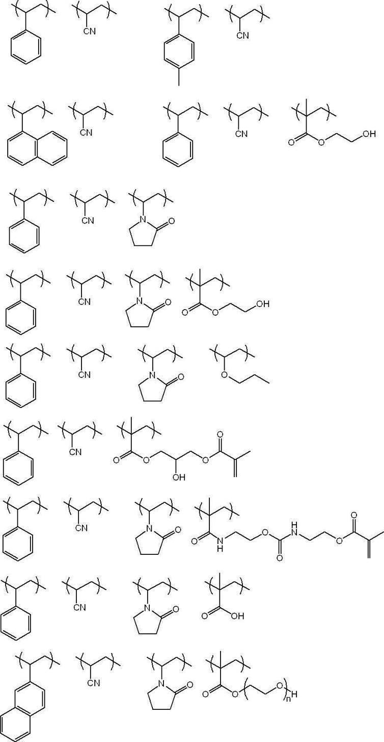
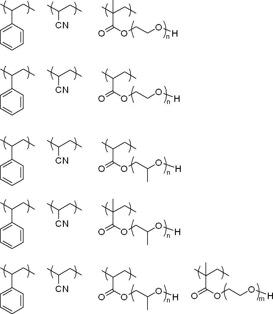
また、上記具体例中、各構成単位の含有比は、上述の各構成単位の含有量の好ましい範囲に従って、適宜変更可能である。
また、上記具体例に示す各化合物の重量平均分子量は、上述の熱可塑性樹脂の重量平均分子量の好ましい範囲に従って、適宜変更可能である。
また、上記具体例に示す各化合物の重量平均分子量は、上述の熱可塑性樹脂の重量平均分子量の好ましい範囲に従って、適宜変更可能である。
-含有量-
画像記録層は、熱可塑性樹脂粒子を1種単独で含有してもよいし、2種以上を併用してもよい。
画像記録層の全質量に対する熱可塑性樹脂粒子の含有量は、UV耐刷性の観点から、5質量%以上90質量%以下であることが好ましく、10質量%以上80質量%以下がより好ましく、10質量%以上60質量%以下が更に好ましい。
画像記録層は、熱可塑性樹脂粒子を1種単独で含有してもよいし、2種以上を併用してもよい。
画像記録層の全質量に対する熱可塑性樹脂粒子の含有量は、UV耐刷性の観点から、5質量%以上90質量%以下であることが好ましく、10質量%以上80質量%以下がより好ましく、10質量%以上60質量%以下が更に好ましい。
〔重合性化合物〕
本開示における画像記録層は、重合性化合物を含む。本開示において、重合性化合物とは、重合性基を有する化合物をいう。
本開示において、重合性を有する化合物であっても、上述の熱可塑性樹脂粒子に含まれる熱可塑性樹脂、後述するポリマー粒子、及び、後述する熱可塑性樹脂以外のバインダーポリマーに該当する化合物は、重合性化合物には該当しないものとする。
重合性基としては、特に限定されず公知の重合性基であればよいが、エチレン性不飽和基であることが好ましい。
また重合性基としては、ラジカル重合性基であってもカチオン重合性基であってもよいが、ラジカル重合性基であることが好ましい。
ラジカル重合性基としては、(メタ)アクリロイル基、アリル基、ビニルフェニル基、ビニル基等が挙げられ、反応性の観点から(メタ)アクリロイル基が好ましい。
重合性化合物の分子量(分子量分布を有する場合には、重量平均分子量)は、50以上2,500未満であることが好ましく、50以上2,000以下であることがより好ましい。また、UV耐刷性、インキ着肉性、耐薬品性、及び、経時での非画像部機上現像性の観点から、重合性化合物の分子量が、1,500以下であることが好ましい。
本開示における画像記録層は、重合性化合物を含む。本開示において、重合性化合物とは、重合性基を有する化合物をいう。
本開示において、重合性を有する化合物であっても、上述の熱可塑性樹脂粒子に含まれる熱可塑性樹脂、後述するポリマー粒子、及び、後述する熱可塑性樹脂以外のバインダーポリマーに該当する化合物は、重合性化合物には該当しないものとする。
重合性基としては、特に限定されず公知の重合性基であればよいが、エチレン性不飽和基であることが好ましい。
また重合性基としては、ラジカル重合性基であってもカチオン重合性基であってもよいが、ラジカル重合性基であることが好ましい。
ラジカル重合性基としては、(メタ)アクリロイル基、アリル基、ビニルフェニル基、ビニル基等が挙げられ、反応性の観点から(メタ)アクリロイル基が好ましい。
重合性化合物の分子量(分子量分布を有する場合には、重量平均分子量)は、50以上2,500未満であることが好ましく、50以上2,000以下であることがより好ましい。また、UV耐刷性、インキ着肉性、耐薬品性、及び、経時での非画像部機上現像性の観点から、重合性化合物の分子量が、1,500以下であることが好ましい。
上記重合性化合物におけるエチレン性不飽和結合1molあたりの質量(「エチレン性不飽和結合当量」ともいう。)は、得られる平版印刷版におけるUV耐刷性の観点から、200g/mol以下であることが好ましく、50g/mol以上200g/mol以下であることがより好ましく、80g/mol以上180g/mol以下であることが更に好ましく、100g/mol以上150g/mol以下であることが特に好ましい。
本開示において、重合性化合物のエチレン性不飽和結合当量を、具体的には例えば、以下のように求めることができる。
・ジペンタエリスリトールヘキサアクリレート(DPHA、分子量578、エチレン性不飽和結合6個)のエチレン性不飽和結合当量:578÷6=96.3(g/mol)
・スチレン(分子量104、エチレン性不飽和結合1個)のエチレン性不飽和結合当量:104÷1=104(g/mol)
・「DPHA10gとスチレン20gとの混合物」のエチレン性不飽和結合当量:(10+20)/{10/96.3+20/104}=101(g/mol)
本開示におけるエチレン性不飽和結合当量は、重合性化合物の分子量及びエチレン性不飽和結合の数、並びに、上記画像記録層中における重合性化合物の組成を、公知の方法により特定し、上記計算方法により求めることができる。
本開示において、重合性化合物のエチレン性不飽和結合当量を、具体的には例えば、以下のように求めることができる。
・ジペンタエリスリトールヘキサアクリレート(DPHA、分子量578、エチレン性不飽和結合6個)のエチレン性不飽和結合当量:578÷6=96.3(g/mol)
・スチレン(分子量104、エチレン性不飽和結合1個)のエチレン性不飽和結合当量:104÷1=104(g/mol)
・「DPHA10gとスチレン20gとの混合物」のエチレン性不飽和結合当量:(10+20)/{10/96.3+20/104}=101(g/mol)
本開示におけるエチレン性不飽和結合当量は、重合性化合物の分子量及びエチレン性不飽和結合の数、並びに、上記画像記録層中における重合性化合物の組成を、公知の方法により特定し、上記計算方法により求めることができる。
本開示に用いられる重合性化合物は、例えば、ラジカル重合性化合物であっても、カチオン重合性化合物であってもよいが、少なくとも1個のエチレン性不飽和結合を有する付加重合性化合物(エチレン性不飽和化合物)であることが好ましい。エチレン性不飽和化合物としては、末端エチレン性不飽和結合を少なくとも1個有する化合物であることが好ましく、末端エチレン性不飽和結合を2個以上有する化合物であることがより好ましい。重合性化合物は、例えばモノマー、プレポリマー、すなわち2量体、3量体若しくはオリゴマー、又は、それらの混合物などの化学的形態をもつ。
中でも、上記重合性化合物としては、UV耐刷性の観点から、3官能以上の重合性化合物を含むことが好ましく、7官能以上の重合性基を含むことがより好ましく、10官能以上の重合性基を含むことが更に好ましい。また、上記重合性化合物は、得られる平版印刷版におけるUV耐刷性の観点から、3官能以上(好ましくは7官能以上、より好ましくは10官能以上)のエチレン性不飽和化合物を含むことが好ましく、3官能以上(好ましくは7官能以上、より好ましくは10官能以上)の(メタ)アクリレート化合物を含むことが更に好ましい。
中でも、上記重合性化合物としては、UV耐刷性の観点から、3官能以上の重合性化合物を含むことが好ましく、7官能以上の重合性基を含むことがより好ましく、10官能以上の重合性基を含むことが更に好ましい。また、上記重合性化合物は、得られる平版印刷版におけるUV耐刷性の観点から、3官能以上(好ましくは7官能以上、より好ましくは10官能以上)のエチレン性不飽和化合物を含むことが好ましく、3官能以上(好ましくは7官能以上、より好ましくは10官能以上)の(メタ)アクリレート化合物を含むことが更に好ましい。
-オリゴマー-
画像記録層に含まれる重合性化合物は、オリゴマーを含有することが好ましい。
本開示においてオリゴマーとは、分子量(分子量分布を有する場合には、重量平均分子量)が600以上10,000以下であり、かつ、重合性基を少なくとも1つ含む重合性化合物を表す。
耐薬品性、UV耐刷性及び機上現像カスの抑制性に優れる観点から、オリゴマーの分子量としては、1,000以上5,000以下であることが好ましい。
画像記録層に含まれる重合性化合物は、オリゴマーを含有することが好ましい。
本開示においてオリゴマーとは、分子量(分子量分布を有する場合には、重量平均分子量)が600以上10,000以下であり、かつ、重合性基を少なくとも1つ含む重合性化合物を表す。
耐薬品性、UV耐刷性及び機上現像カスの抑制性に優れる観点から、オリゴマーの分子量としては、1,000以上5,000以下であることが好ましい。
また、耐薬品性及びUV耐刷性を向上させる観点から、1分子のオリゴマーにおける重合性基数は、2以上であることが好ましく、3以上であることがより好ましく、6以上であることが更に好ましく、10以上であることが特に好ましい。
また、オリゴマーにおける重合性基の上限値は、特に制限はないが、重合性基の数は20以下であることが好ましい。
また、オリゴマーにおける重合性基の上限値は、特に制限はないが、重合性基の数は20以下であることが好ましい。
耐薬品性、UV耐刷性及び機上現像カスの抑制性により優れる観点から、オリゴマーとしては、重合性基の数が7以上であり、かつ、分子量が1,000以上10,000以下であることが好ましく、重合性基の数が7以上20以下であり、かつ、分子量が1,000以上5,000以下であることがより好ましい。
耐薬品性及びUV耐刷性により優れる観点から、オリゴマーは、ウレタン結合を有する化合物、エステル結合を有する化合物及びエポキシ残基を有する化合物からなる群より選ばれる少なくとも1種を有することが好ましく、ウレタン結合を有する化合物を有することが好ましい。
本明細書においてエポキシ残基とは、エポキシ基により形成される構造を指し、例えば酸基(カルボン酸基等)とエポキシ基との反応により得られる構造と同様の構造を意味する。
本明細書においてエポキシ残基とは、エポキシ基により形成される構造を指し、例えば酸基(カルボン酸基等)とエポキシ基との反応により得られる構造と同様の構造を意味する。
<<ウレタン結合を有する化合物>>
ウレタン結合を有する化合物としては、特に限定されないが、例えば、ポリイソシアネート化合物と、ヒドロキシ基及び重合性基を有する化合物との反応により得られる化合物が挙げられる。
ウレタン結合を有する化合物としては、特に限定されないが、例えば、ポリイソシアネート化合物と、ヒドロキシ基及び重合性基を有する化合物との反応により得られる化合物が挙げられる。
ポリイソシアネート化合物としては、2官能~5官能のポリイソシアネート化合物が挙げられ、2官能又は3官能のポリイソシアネート化合物が好ましい。
ポリイソシアネート化合物としては、1,3-ビス(イソシアナトメチル)シクロヘキサン、ジイソシアン酸イソホロン、トリメチレンジイソシアネート、テトラメチレンジイソシアネート、ペンタメチレンジイソシアネート、ヘキサメチレンジイソシアネート、1,3-シクロペンタンジイソシアネート、9H-フルオレン-2,7-ジイソシアネート、9H-フルオレン-9-オン-2,7-ジイソシアネート、4,4’-ジフェニルメタンジイソシアナート、1,3-フェニレンジイソシアナート、トリレン-2,4-ジイソシアナート、トリレン-2,6-ジイソシアナート、1,3-ビス(イソシアナトメチル)シクロヘキサン、2,2-ビス(4-イソシアナトフェニル)ヘキサフルオロプロパン、1,5-ジイソシアナトナフタレン、これらのポリイソシアネートのダイマー、トリマー(イソシアヌレート結合)等が好ましく挙げられる。また、上記のポリイソシアネート化合物と公知のアミン化合物とを反応させたビウレット体を用いてもよい。
ポリイソシアネート化合物としては、1,3-ビス(イソシアナトメチル)シクロヘキサン、ジイソシアン酸イソホロン、トリメチレンジイソシアネート、テトラメチレンジイソシアネート、ペンタメチレンジイソシアネート、ヘキサメチレンジイソシアネート、1,3-シクロペンタンジイソシアネート、9H-フルオレン-2,7-ジイソシアネート、9H-フルオレン-9-オン-2,7-ジイソシアネート、4,4’-ジフェニルメタンジイソシアナート、1,3-フェニレンジイソシアナート、トリレン-2,4-ジイソシアナート、トリレン-2,6-ジイソシアナート、1,3-ビス(イソシアナトメチル)シクロヘキサン、2,2-ビス(4-イソシアナトフェニル)ヘキサフルオロプロパン、1,5-ジイソシアナトナフタレン、これらのポリイソシアネートのダイマー、トリマー(イソシアヌレート結合)等が好ましく挙げられる。また、上記のポリイソシアネート化合物と公知のアミン化合物とを反応させたビウレット体を用いてもよい。
ヒドロキシ基及び重合性基を有する化合物としては、1つのヒドロキシ基と、1以上の重合性基とを有する化合物が好ましく、1つのヒドロキシ基と、2以上の重合性基とを有する化合物がより好ましい。
ヒドロキシ基及び重合性基を有する化合物としては、ヒドロキシエチル(メタ)アクリレート、グリセリンジ(メタ)アクリレート、トリメチロールプロパンジ(メタ)アクリレート、ペンタエリスリトールトリ(メタ)アクリレート、ジペンタエリスリトールペンタ(メタ)アクリレート等が挙げられる。
ヒドロキシ基及び重合性基を有する化合物としては、ヒドロキシエチル(メタ)アクリレート、グリセリンジ(メタ)アクリレート、トリメチロールプロパンジ(メタ)アクリレート、ペンタエリスリトールトリ(メタ)アクリレート、ジペンタエリスリトールペンタ(メタ)アクリレート等が挙げられる。
ウレタン結合を有する化合物としては、例えば、下記式(Ac-1)又は式(Ac-2)で表される基を少なくとも有する化合物であることが好ましく、下記式(Ac-1)で表される基を少なくとも有する化合物であることがより好ましい。
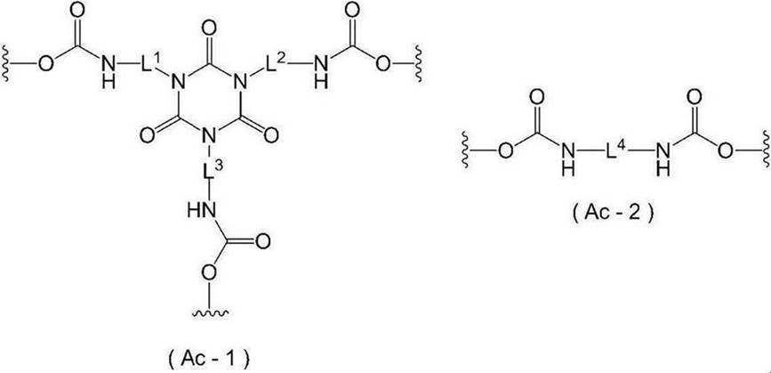
式(Ac-1)及び式(Ac-2)中、L1~L4はそれぞれ独立に、炭素数2~20の二価の炭化水素基を表し、波線部分は他の構造との結合位置を表す。
L1~L4としては、それぞれ独立に、炭素数2~20のアルキレン基であることが好ましく、炭素数2~10のアルキレン基であることがより好ましく、炭素数4~8のアルキレン基であることが更に好ましい。また、上記アルキレン基は、分岐又は環構造を有していてもよいが、直鎖アルキレン基であることが好ましい。
L1~L4としては、それぞれ独立に、炭素数2~20のアルキレン基であることが好ましく、炭素数2~10のアルキレン基であることがより好ましく、炭素数4~8のアルキレン基であることが更に好ましい。また、上記アルキレン基は、分岐又は環構造を有していてもよいが、直鎖アルキレン基であることが好ましい。
式(Ac-1)又は式(Ac-2)における波線部はそれぞれ独立に、下記式(Ae-1)又は式(Ae-2)で表される基における波線部と直接結合することが好ましい。
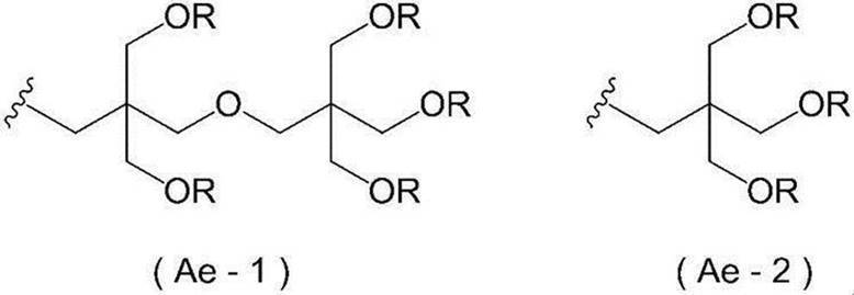
式(Ae-1)及び式(Ae-2)中、Rはそれぞれ独立に、アクリロイルオキシ基又はメタクリロイルオキシ基を表し、波線部分は式(Ac-1)及び式(Ac-2)における波線部との結合位置を表す。
また、ウレタン結合を有する化合物として、ポリイソシアネート化合物と、ポリオール化合物と、の反応により得られるポリウレタンに、高分子反応により重合性基を導入した化合物を用いてもよい。例えば、酸基を有するポリオール化合物と、ポリイソシアネート化合物を反応させて得られたポリウレタンオリゴマーに、エポキシ基及び重合性基を有する化合物を反応させることにより、ウレタン結合を有する化合物を得てもよい。
<<エステル結合を有する化合物>>
また、エステル結合を有する化合物における重合性基の数は、3以上であることが好ましく、6以上であることが更に好ましい。
また、エステル結合を有する化合物における重合性基の数は、3以上であることが好ましく、6以上であることが更に好ましい。
<<エポキシ残基を有する化合物>>
エポキシ残基を有する化合物としては、化合物内にヒドロキシ基を含む化合物が好ましい。
また、エポキシ残基を有する化合物における重合性基の数は、2~6であることが好ましく、2~3であることがより好ましい。
上記エポキシ残基を有する化合物としては、例えば、エポキシ基を有する化合物にアクリル酸を反応することにより得ることができる。
エポキシ残基を有する化合物としては、化合物内にヒドロキシ基を含む化合物が好ましい。
また、エポキシ残基を有する化合物における重合性基の数は、2~6であることが好ましく、2~3であることがより好ましい。
上記エポキシ残基を有する化合物としては、例えば、エポキシ基を有する化合物にアクリル酸を反応することにより得ることができる。
耐薬品性、UV耐刷性及び機上現像カスの抑制性を向上させる観点から、上記画像記録層における上記重合性化合物の全質量に対する上記オリゴマーの含有量は、30質量%~100質量%であることが好ましく、50質量%~100質量%であることがより好ましく、80質量%~100質量%であることが更に好ましい。
重合性化合物は、上記オリゴマー以外の重合性化合物を更に含んでいてもよい。
オリゴマー以外の重合性化合物は、例えば、ラジカル重合性化合物であっても、カチオン重合性化合物であってもよいが、少なくとも1つのエチレン性不飽和基を有する付加重合性化合物(エチレン性不飽和化合物)であることが好ましい。エチレン性不飽和化合物としては、末端にエチレン性不飽和基を少なくとも1つ有する化合物であることが好ましく、末端にエチレン性不飽和基を2つ以上有する化合物であることがより好ましい。
オリゴマー以外の重合性化合物としては、耐薬品性の観点から、低分子重合性化合物であることが好ましい。低分子重合性化合物としては、単量体、2量体、3量体又は、それらの混合物などの化学的形態であってもよい。
また、低分子重合性化合物としては、耐薬品性の観点から、エチレン性不飽和基を3つ以上有する重合性化合物及びイソシアヌル環構造を有する重合性化合物からなる群より選ばれる少なくとも一方の重合性化合物であることが好ましい。
オリゴマー以外の重合性化合物は、例えば、ラジカル重合性化合物であっても、カチオン重合性化合物であってもよいが、少なくとも1つのエチレン性不飽和基を有する付加重合性化合物(エチレン性不飽和化合物)であることが好ましい。エチレン性不飽和化合物としては、末端にエチレン性不飽和基を少なくとも1つ有する化合物であることが好ましく、末端にエチレン性不飽和基を2つ以上有する化合物であることがより好ましい。
オリゴマー以外の重合性化合物としては、耐薬品性の観点から、低分子重合性化合物であることが好ましい。低分子重合性化合物としては、単量体、2量体、3量体又は、それらの混合物などの化学的形態であってもよい。
また、低分子重合性化合物としては、耐薬品性の観点から、エチレン性不飽和基を3つ以上有する重合性化合物及びイソシアヌル環構造を有する重合性化合物からなる群より選ばれる少なくとも一方の重合性化合物であることが好ましい。
本開示において低分子重合性化合物とは、分子量(分子量分布を有する場合には、重量平均分子量)50以上600未満の重合性化合物を表す。
低分子重合性化合物の分子量としては、耐薬品性、UV耐刷性及び機上現像カスの抑制性に優れる観点から、100以上600未満であることが好ましく、300以上600未満であることがより好ましく、400以上600未満であることが更に好ましい。
重合性化合物が、オリゴマー以外の重合性化合物として低分子重合性化合物を含む場合(2種以上の低分子重合性化合物を含む場合はその合計量)、耐薬品性、UV耐刷性及び機上現像カスの抑制性の観点から、上記オリゴマーと低分子重合性化合物との比(オリゴマー/低分子重合性化合物)は、質量基準で、10/1~1/10であることが好ましく、10/1~3/7であることがより好ましく、10/1~7/3であることが更に好ましい。
低分子重合性化合物の分子量としては、耐薬品性、UV耐刷性及び機上現像カスの抑制性に優れる観点から、100以上600未満であることが好ましく、300以上600未満であることがより好ましく、400以上600未満であることが更に好ましい。
重合性化合物が、オリゴマー以外の重合性化合物として低分子重合性化合物を含む場合(2種以上の低分子重合性化合物を含む場合はその合計量)、耐薬品性、UV耐刷性及び機上現像カスの抑制性の観点から、上記オリゴマーと低分子重合性化合物との比(オリゴマー/低分子重合性化合物)は、質量基準で、10/1~1/10であることが好ましく、10/1~3/7であることがより好ましく、10/1~7/3であることが更に好ましい。
重合性化合物の例としては、不飽和カルボン酸(例えば、アクリル酸、メタクリル酸、イタコン酸、クロトン酸、イソクロトン酸、マレイン酸など)及び、そのエステル類、アミド類が挙げられ、好ましくは、不飽和カルボン酸と多価アルコール化合物とのエステル類、不飽和カルボン酸と多価アミン化合物とのアミド類が用いられる。また、ヒドロキシ基、アミノ基、メルカプト基等の求核性置換基を有する不飽和カルボン酸エステル類、又は、アミド類と単官能若しくは多官能イソシアネート類又はエポキシ類との付加反応物、及び単官能若しくは多官能のカルボン酸との脱水縮合反応物等も好適に使用される。また、イソシアネート基、エポキシ基等の親電子性置換基を有する不飽和カルボン酸エステル類あるいはアミド類と単官能又は多官能のアルコール類、アミン類、チオール類との付加反応物、更にハロゲン原子、トシルオキシ基等の脱離性置換基を有する不飽和カルボン酸エステル類あるいはアミド類と単官能又は多官能のアルコール類、アミン類、チオール類との置換反応物も好適である。また、別の例として、上記の不飽和カルボン酸を、不飽和ホスホン酸、スチレン、ビニルエーテル等に置き換えた化合物群を使用することも可能である。これらは、特表2006-508380号公報、特開2002-287344号公報、特開2008-256850号公報、特開2001-342222号公報、特開平9-179296号公報、特開平9-179297号公報、特開平9-179298号公報、特開2004-294935号公報、特開2006-243493号公報、特開2002-275129号公報、特開2003-64130号公報、特開2003-280187号公報、特開平10-333321号公報等に記載されている。
多価アルコール化合物と不飽和カルボン酸とのエステルのモノマーの具体例としては、アクリル酸エステルとして、エチレングリコールジアクリレート、1,3-ブタンジオールジアクリレート、テトラメチレングリコールジアクリレート、プロピレングリコールジアクリレート、トリメチロールプロパントリアクリレート、ヘキサンジオールジアクリレート、テトラエチレングリコールジアクリレート、ペンタエリスリトールテトラアクリレート、ソルビトールトリアクリレート、イソシアヌル酸エチレンオキシド(EO)変性トリアクリレート、ポリエステルアクリレートオリゴマー等がある。メタクリル酸エステルとして、テトラメチレングリコールジメタクリレート、ネオペンチルグリコールジメタクリレート、トリメチロールプロパントリメタクリレート、エチレングリコールジメタクリレート、ペンタエリスリトールトリメタクリレート、ビス〔p-(3-メタクリルオキシ-2-ヒドロキシプロポキシ)フェニル〕ジメチルメタン、ビス〔p-(メタクリルオキシエトキシ)フェニル〕ジメチルメタン等がある。また、多価アミン化合物と不飽和カルボン酸とのアミドのモノマーの具体例としては、メチレンビスアクリルアミド、メチレンビスメタクリルアミド、1,6-ヘキサメチレンビスアクリルアミド、1,6-ヘキサメチレンビスメタクリルアミド、ジエチレントリアミントリスアクリルアミド、キシリレンビスアクリルアミド、キシリレンビスメタクリルアミド等がある。
また、イソシアネートとヒドロキシ基の付加反応を用いて製造されるウレタン系付加重合性化合物も好適であり、その具体例としては、例えば、特公昭48-41708号公報に記載されている1分子に2個以上のイソシアネート基を有するポリイソシアネート化合物に、下記式(M)で表されるヒドロキシ基を含有するビニルモノマーを付加させた1分子中に2個以上の重合性ビニル基を含有するビニルウレタン化合物等が挙げられる。
CH2=C(RM4)COOCH2CH(RM5)OH (M)
式(M)中、RM4及びRM5はそれぞれ独立に、水素原子又はメチル基を表す。
CH2=C(RM4)COOCH2CH(RM5)OH (M)
式(M)中、RM4及びRM5はそれぞれ独立に、水素原子又はメチル基を表す。
また、特開昭51-37193号公報、特公平2-32293号公報、特公平2-16765号公報、特開2003-344997号公報、特開2006-65210号公報に記載のウレタンアクリレート類、特公昭58-49860号公報、特公昭56-17654号公報、特公昭62-39417号公報、特公昭62-39418号公報、特開2000-250211号公報、特開2007-94138号公報に記載のエチレンオキサイド系骨格を有するウレタン化合物類、米国特許第7153632号明細書、特表平8-505958号公報、特開2007-293221号公報、特開2007-293223号公報に記載の親水基を有するウレタン化合物類も好適である。
オリゴマーの具体例を下記表に示すが、本開示において用いられるオリゴマーはこれに限定されるものではない。
オリゴマーとしては、市販品を用いてもよく、UA510H、UA-306H、UA-306I、UA-306T(いずれも共栄社化学(株)製)、UV-1700B、UV-6300B、UV7620EA(いずれも日本合成化学工業(株)製)、U-15HA(新中村化学工業(株)製)、EBECRYL450、EBECRYL657、EBECRYL885、EBECRYL800、EBECRYL3416、EBECRYL860(いずれもダイセルオルネクス(株)製)等が挙げられるが、これに限定されるものではない。
重合性化合物の構造、単独使用か併用か、添加量等の使用方法の詳細は、任意に設定できる。
中でも、上記画像記録層は、UV耐刷性の観点から、2種以上の重合性化合物を含むことが好ましい。
重合性化合物の含有量(重合性化合物を2種以上含む場合は、重合性化合物の総含有量)は、画像記録層の全質量に対して、5質量%~75質量%であることが好ましく、10質量%~70質量%であることがより好ましく、15質量%~60質量%であることが更に好ましい。
また、上記画像記録層における上記重合性化合物の全質量に対する熱可塑性樹脂粒子に含まれる熱可塑性樹脂の含有量は、0質量%を超え400質量%以下であることが好ましく、25質量%~300質量%であることがより好ましく、50質量%~200質量%であることが更に好ましい。
画像記録層において、熱可塑性樹脂粒子に含まれる熱可塑性樹脂と上記重合性化合物とは、海島構造をとることが好ましい。例えば、熱可塑性樹脂の海(連続相)の中に、上記重合性化合物が島状に分散(不連続層)した構造を採用することができる。上記重合性化合物の全質量に対する上記熱可塑性樹脂粒子に含まれる熱可塑性樹脂の含有量を上記範囲内の値とすることにより、海島構造を形成しやすいと考えられる。
中でも、上記画像記録層は、UV耐刷性の観点から、2種以上の重合性化合物を含むことが好ましい。
重合性化合物の含有量(重合性化合物を2種以上含む場合は、重合性化合物の総含有量)は、画像記録層の全質量に対して、5質量%~75質量%であることが好ましく、10質量%~70質量%であることがより好ましく、15質量%~60質量%であることが更に好ましい。
また、上記画像記録層における上記重合性化合物の全質量に対する熱可塑性樹脂粒子に含まれる熱可塑性樹脂の含有量は、0質量%を超え400質量%以下であることが好ましく、25質量%~300質量%であることがより好ましく、50質量%~200質量%であることが更に好ましい。
画像記録層において、熱可塑性樹脂粒子に含まれる熱可塑性樹脂と上記重合性化合物とは、海島構造をとることが好ましい。例えば、熱可塑性樹脂の海(連続相)の中に、上記重合性化合物が島状に分散(不連続層)した構造を採用することができる。上記重合性化合物の全質量に対する上記熱可塑性樹脂粒子に含まれる熱可塑性樹脂の含有量を上記範囲内の値とすることにより、海島構造を形成しやすいと考えられる。
〔重合開始剤〕
本開示において用いられる画像記録層は、重合開始剤を含有する。
重合性開始剤としては、特に制限はなく、電子受容型重合開始剤、電子供与型重合開始剤等が挙げられる。
本開示において用いられる画像記録層は、重合開始剤を含有する。
重合性開始剤としては、特に制限はなく、電子受容型重合開始剤、電子供与型重合開始剤等が挙げられる。
-電子受容型重合開始剤-
上記画像記録層は、電子受容型重合開始剤を含むことが好ましい。
本開示に用いられる電子受容型重合開始剤は、光、熱又はその両方のエネルギーによりラジカルやカチオン等の重合開始種を発生する化合物であって、公知の熱重合開始剤、結合解離エネルギーの小さな結合を有する化合物、光重合開始剤などを適宜選択して用いることができる。
電子受容型重合開始剤としては、ラジカル重合開始剤が好ましく、オニウム化合物がより好ましい。
また、電子受容型重合開始剤としては、赤外線感光性重合開始剤であることが好ましい。
電子受容型重合開始剤は、1種単独で用いてもよく、2種以上を併用してもよい。
ラジカル重合開始剤としては、例えば、(a)有機ハロゲン化物、(b)カルボニル化合物、(c)アゾ化合物、(d)有機過酸化物、(e)メタロセン化合物、(f)アジド化合物、(g)ヘキサアリールビイミダゾール化合物、(i)ジスルホン化合物、(j)オキシムエステル化合物、(k)オニウム化合物が挙げられる。
上記画像記録層は、電子受容型重合開始剤を含むことが好ましい。
本開示に用いられる電子受容型重合開始剤は、光、熱又はその両方のエネルギーによりラジカルやカチオン等の重合開始種を発生する化合物であって、公知の熱重合開始剤、結合解離エネルギーの小さな結合を有する化合物、光重合開始剤などを適宜選択して用いることができる。
電子受容型重合開始剤としては、ラジカル重合開始剤が好ましく、オニウム化合物がより好ましい。
また、電子受容型重合開始剤としては、赤外線感光性重合開始剤であることが好ましい。
電子受容型重合開始剤は、1種単独で用いてもよく、2種以上を併用してもよい。
ラジカル重合開始剤としては、例えば、(a)有機ハロゲン化物、(b)カルボニル化合物、(c)アゾ化合物、(d)有機過酸化物、(e)メタロセン化合物、(f)アジド化合物、(g)ヘキサアリールビイミダゾール化合物、(i)ジスルホン化合物、(j)オキシムエステル化合物、(k)オニウム化合物が挙げられる。
(a)有機ハロゲン化物としては、例えば、特開2008-195018号公報の段落0022~0023に記載の化合物が好ましい。
(b)カルボニル化合物としては、例えば、特開2008-195018号公報の段落0024に記載の化合物が好ましい。
(c)アゾ化合物としては、例えば、特開平8-108621号公報に記載のアゾ化合物等を使用することができる。
(d)有機過酸化物としては、例えば、特開2008-195018号公報の段落0025に記載の化合物が好ましい。
(e)メタロセン化合物としては、例えば、特開2008-195018号公報の段落0026に記載の化合物が好ましい。
(f)アジド化合物としては、例えば、2,6-ビス(4-アジドベンジリデン)-4-メチルシクロヘキサノン等の化合物を挙げることができる。
(g)ヘキサアリールビイミダゾール化合物としては、例えば、特開2008-195018号公報の段落0027に記載の化合物が好ましい。
(i)ジスルホン化合物としては、例えば、特開昭61-166544号、特開2002-328465号の各公報に記載の化合物が挙げられる。
(j)オキシムエステル化合物としては、例えば、特開2008-195018号公報の段落0028~0030に記載の化合物が好ましい。
(b)カルボニル化合物としては、例えば、特開2008-195018号公報の段落0024に記載の化合物が好ましい。
(c)アゾ化合物としては、例えば、特開平8-108621号公報に記載のアゾ化合物等を使用することができる。
(d)有機過酸化物としては、例えば、特開2008-195018号公報の段落0025に記載の化合物が好ましい。
(e)メタロセン化合物としては、例えば、特開2008-195018号公報の段落0026に記載の化合物が好ましい。
(f)アジド化合物としては、例えば、2,6-ビス(4-アジドベンジリデン)-4-メチルシクロヘキサノン等の化合物を挙げることができる。
(g)ヘキサアリールビイミダゾール化合物としては、例えば、特開2008-195018号公報の段落0027に記載の化合物が好ましい。
(i)ジスルホン化合物としては、例えば、特開昭61-166544号、特開2002-328465号の各公報に記載の化合物が挙げられる。
(j)オキシムエステル化合物としては、例えば、特開2008-195018号公報の段落0028~0030に記載の化合物が好ましい。
上記電子受容型重合開始剤の中でも好ましいものとして、硬化性の観点から、オキシムエステル化合物及びオニウム化合物が挙げられる。中でも、UV耐刷性の観点から、ヨードニウム塩化合物、スルホニウム塩化合物又はアジニウム塩化合物が好ましく、ヨードニウム塩化合物又はスルホニウム塩化合物がより好ましく、ヨードニウム塩化合物が更に好ましい。
これら化合物の具体例を以下に示すが、本開示はこれに限定されるものではない。
これら化合物の具体例を以下に示すが、本開示はこれに限定されるものではない。
ヨードニウム塩化合物の例としては、ジアリールヨードニウム塩化合物が好ましく、特に電子供与性基、例えば、アルキル基又はアルコキシル基で置換されたジフェニルヨードニウム塩化合物がより好ましく、また、非対称のジフェニルヨードニウム塩化合物が好ましい。具体例としては、ジフェニルヨードニウム=ヘキサフルオロホスファート、4-メトキシフェニル-4-(2-メチルプロピル)フェニルヨードニウム=ヘキサフルオロホスファート、4-(2-メチルプロピル)フェニル-p-トリルヨードニウム=ヘキサフルオロホスファート、4-ヘキシルオキシフェニル-2,4,6-トリメトキシフェニルヨードニウム=ヘキサフルオロホスファート、4-ヘキシルオキシフェニル-2,4-ジエトキシフェニルヨードニウム=テトラフルオロボラート、4-オクチルオキシフェニル-2,4,6-トリメトキシフェニルヨードニウム=1-ペルフルオロブタンスルホナート、4-オクチルオキシフェニル-2,4,6-トリメトキシフェニルヨードニウム=ヘキサフルオロホスファート、ビス(4-t-ブチルフェニル)ヨードニウム=ヘキサフルオロホスファートが挙げられる。
スルホニウム塩化合物の例としては、トリアリールスルホニウム塩化合物が好ましく、特に電子求引性基、例えば、芳香環上の基の少なくとも一部がハロゲン原子で置換されたトリアリールスルホニウム塩化合物が好ましく、芳香環上のハロゲン原子の総置換数が4以上であるトリアリールスルホニウム塩化合物が更に好ましい。具体例としては、トリフェニルスルホニウム=ヘキサフルオロホスファート、トリフェニルスルホニウム=ベンゾイルホルマート、ビス(4-クロロフェニル)フェニルスルホニウム=ベンゾイルホルマート、ビス(4-クロロフェニル)-4-メチルフェニルスルホニウム=テトラフルオロボラート、トリス(4-クロロフェニル)スルホニウム=3,5-ビス(メトキシカルボニル)ベンゼンスルホナート、トリス(4-クロロフェニル)スルホニウム=ヘキサフルオロホスファート、トリス(2,4-ジクロロフェニル)スルホニウム=ヘキサフルオロホスファートが挙げられる。
また、ヨードニウム塩化合物及びスルホニウム塩化合物の対アニオンとしては、スルホンアミドアニオン又はスルホンイミドアニオンが好ましく、スルホンイミドアニオンがより好ましい。
スルホンアミドアニオンとしては、アリールスルホンアミドアニオンが好ましい。
また、スルホンイミドアニオンとしては、ビスアリールスルホンイミドアニオンが好ましい。
スルホンアミドアニオン又はスルホンイミドアニオンの具体例を以下に示すが、本開示はこれらに限定されるものではない。下記具体例中、Phはフェニル基を、Meはメチル基を、Etはエチル基を、それぞれ表す。
スルホンアミドアニオンとしては、アリールスルホンアミドアニオンが好ましい。
また、スルホンイミドアニオンとしては、ビスアリールスルホンイミドアニオンが好ましい。
スルホンアミドアニオン又はスルホンイミドアニオンの具体例を以下に示すが、本開示はこれらに限定されるものではない。下記具体例中、Phはフェニル基を、Meはメチル基を、Etはエチル基を、それぞれ表す。
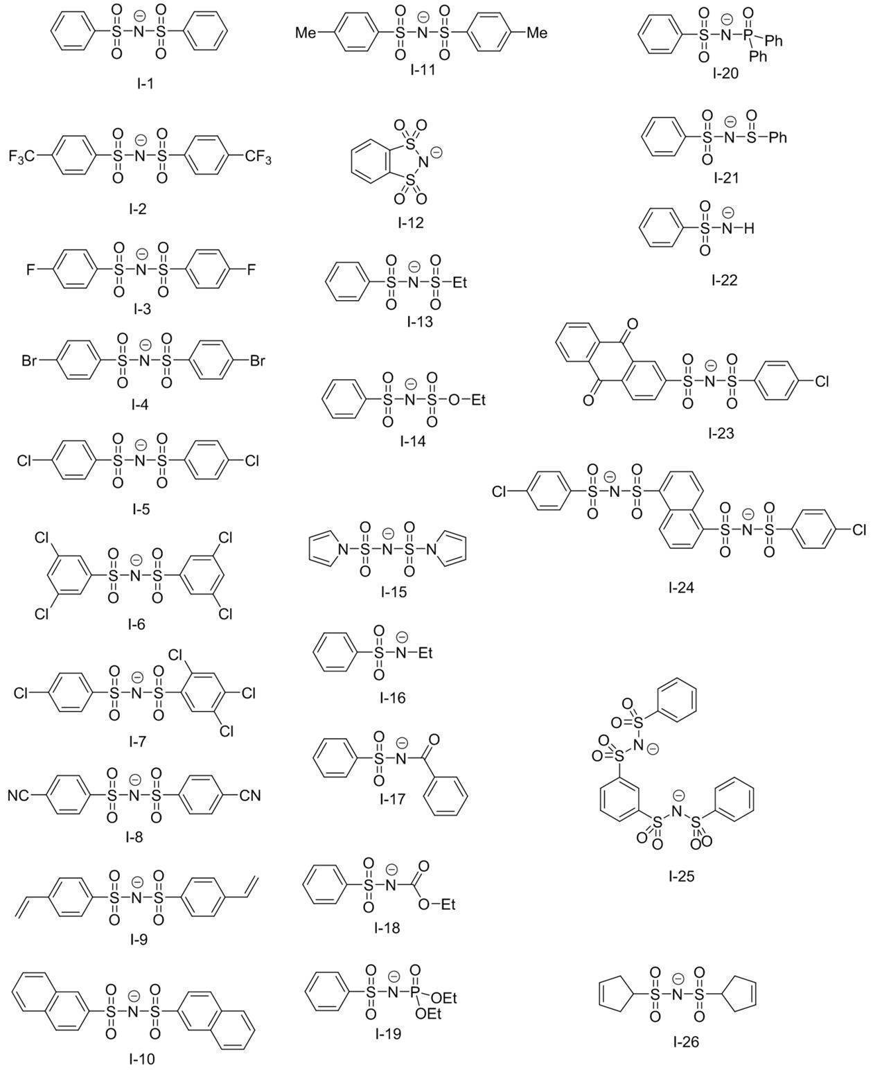
上記電子受容型重合開始剤と後述の電子供与型重合開始剤とが塩を形成している態様の具体例を以下に示すが、本開示はこれらに限定されるものではない。
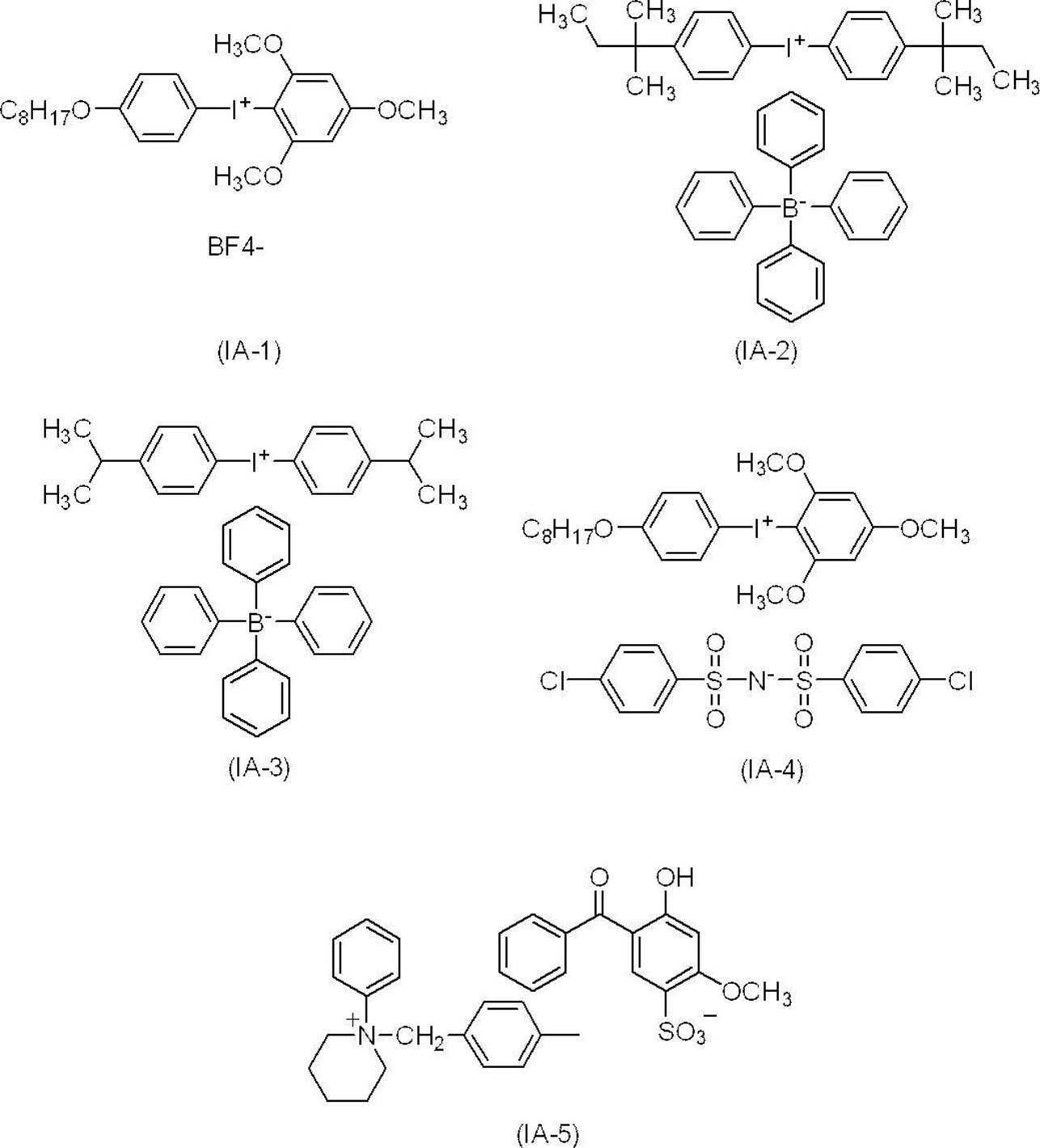
また、上記電子受容型重合開始剤は、発色性、露光後経時発色性、現像性、及び、得られる平版印刷版原版におけるUV耐刷性の観点から、下記式(I)で表される化合物を好適に用いることができる。

式中、Xはハロゲン原子を表し、具体的には、フッ素原子、塩素原子、臭素原子及びヨウ素原子が挙げられる。これらのうち、塩素原子又は臭素原子は、感度に優れるため好ましく、臭素原子が特に好ましい。
Aは-CO-、-SO-、-SO2-、-PO-及び-PO2-よりなる群から選ばれる2価の連結基を表す。これらのうち、-CO-、-SO-及び-SO2-がより好ましく、-CO-及び-SO2-が特に好ましい。RX1及びRX2はそれぞれ独立して、水素原子又は炭素原子数1~20までの1価の炭化水素基を表す。
炭化水素基を構成する炭化水素としては、特開2002-162741号公報の段落0013~段落0014に記載の炭化水素等を挙げることができるが、具体的には、炭化水素としては、メタン、エタン、プロパン、ブタン、ヘキサン、ノナン、デカン、オクタデカン、シクロペンタン、シクロヘキサン、アダマンタン、ノルボルナン、デカヒドロナフタレン、トリシクロ[5.2.1.02,6]デカン、エチレン、プロピレン、1-ブテン、1-ヘキセン、1-ヘプタデセン、2-ブテン、2-ヘキセン、4-ノネン、7-テトラデセン、ブタジエン、ピペリレン、1,9-デカジエン、シクロペンテン、シクロヘキセン、シクロオクテン、1,4-シクロヘキサジエン、1,5-シクロオクタジエン、1,5,9-シクロドデカトリエン、ノルボルニレン、オクタヒドロナフタレン、ピシクロ[2.2.1]ヘプタ-2,5-ジエン、アセチレン、1-プロピン、2-ヘキシン等の炭素数1から30までの脂肪族炭化水素;ベンゼン、ナフタレン、アントラセン、インデン、フルオレン等の芳香族炭化水素が挙げられる。
このような炭化水素基を構成する炭素原子は、酸素原子、窒素原子及び硫黄原子から選ばれるヘテロ原子で1個以上置換されてもよい。
Aは-CO-、-SO-、-SO2-、-PO-及び-PO2-よりなる群から選ばれる2価の連結基を表す。これらのうち、-CO-、-SO-及び-SO2-がより好ましく、-CO-及び-SO2-が特に好ましい。RX1及びRX2はそれぞれ独立して、水素原子又は炭素原子数1~20までの1価の炭化水素基を表す。
炭化水素基を構成する炭化水素としては、特開2002-162741号公報の段落0013~段落0014に記載の炭化水素等を挙げることができるが、具体的には、炭化水素としては、メタン、エタン、プロパン、ブタン、ヘキサン、ノナン、デカン、オクタデカン、シクロペンタン、シクロヘキサン、アダマンタン、ノルボルナン、デカヒドロナフタレン、トリシクロ[5.2.1.02,6]デカン、エチレン、プロピレン、1-ブテン、1-ヘキセン、1-ヘプタデセン、2-ブテン、2-ヘキセン、4-ノネン、7-テトラデセン、ブタジエン、ピペリレン、1,9-デカジエン、シクロペンテン、シクロヘキセン、シクロオクテン、1,4-シクロヘキサジエン、1,5-シクロオクタジエン、1,5,9-シクロドデカトリエン、ノルボルニレン、オクタヒドロナフタレン、ピシクロ[2.2.1]ヘプタ-2,5-ジエン、アセチレン、1-プロピン、2-ヘキシン等の炭素数1から30までの脂肪族炭化水素;ベンゼン、ナフタレン、アントラセン、インデン、フルオレン等の芳香族炭化水素が挙げられる。
このような炭化水素基を構成する炭素原子は、酸素原子、窒素原子及び硫黄原子から選ばれるヘテロ原子で1個以上置換されてもよい。
置換基としては水素を除く、1価の非金属原子団を挙げることができ、ハロゲン原子(-F、-Br、-Cl、-I)、ヒドロキシル基、アルコキシ基、アリーロキシ基、メルカプト基、アルキルチオ基、アリールチオ基、アルキルジチオ基、アリールジチオ基、アミノ基、N-アルキルアミノ基、N,N-ジアルキルアミノ基、N-アリールアミノ基、N,N-ジアリールアミノ基、N-アルキル-N-アリールアミノ基、アシルオキシ基、カルバモイルオキシ基、N-アルキルカルバモイルオキシ基、N-アリールカルバモイルオキシ基、N,N-ジアルキルカルバモイルオキシ基、N,N-ジアリールカルバモイルオキシ基、N-アルキル-N-アリールカルバモイルオキシ基、アルキルスルホキシ基、アリールスルホキシ基、アシルチオ基、アシルアミノ基、N-アルキルアシルアミノ基、N-アリールアシルアミノ基、ウレイド基、N’-アルキルウレイド基、N’,N’-ジアルキルウレイド基、N’-アリールウレイド基、N’,N’-ジアリールウレイド基、N’-アルキル-N’-アリールウレイド基、N-アルキルウレイド基、N-アリールウレイド基、N’-アルキル-N-アルキルウレイド基、N’-アルキル-N-アリールウレイド基、N’,N’-ジアルキル-N-アルキルウレイド基、N’,N’-ジアルキル-N-アリールウレイド基、N’-アリール-N-アルキルウレイド基、N’-アリール-N-アリールウレイド基、N’,N’-ジアリール-N-アルキルウレイド基、N’,N’-ジアリール-N-アリールウレイド基、N’-アルキル-N’-アリール-N-アルキルウレイド基、N’-アルキル-N’-アリール-N-アリールウレイド基、アルコキシカルボニルアミノ基、アリーロキシカルボニルアミノ基、N-アルキル-N-アルコキシカルボニルアミノ基、N-アルキル-N-アリーロキシカルボニルアミノ基、N-アリール-N-アルコキシカルボニルアミノ基、N-アリール-N-アリーロキシカルボニルアミノ基、ホルミル基、アシル基、カルボキシル基及びその共役塩基基、アルコキシカルボニル基、アリーロキシカルボニル基、カルバモイル基、N-アルキルカルバモイル基、N,N-ジアルキルカルバモイル基、N-アリールカルバモイル基、N,N-ジアリールカルバモイル基、N-アルキル-N-アリールカルバモイル基、アルキルスルフィニル基、アリールスルフィニル基、アルキルスルホニル基、アリールスルホニル基、スルホ基(-SO3H)及びその共役塩基基、アルコキシスルホニル基、アリーロキシスルホニル基、スルフィナモイル基、N-アルキルスルフィナモイル基、N,N-ジアルキルスルフィナモイル基、N-アリールスルフィナモイル基、N,N-ジアリールスルフィナモイル基、N-アルキル-N-アリールスルフィナモイル基、スルファモイル基、N-アルキルスルファモイル基、N,N-ジアルキルスルファモイル基、N-アリールスルファモイル基、N,N-ジアリールスルファモイル基、N-アルキル-N-アリールスルファモイル基、N-アシルスルファモイル基及びその共役塩基基、N-アルキルスルホニルスルファモイル基(-SO2NHSO2(alkyl))及びその共役塩基基、N-アリールスルホニルスルファモイル基(-SO2NHSO2(aryl))及びその共役塩基基、N-アルキルスルホニルカルバモイル基(-CONHSO2(alkyl))及びその共役塩基基、N-アリールスルホニルカルバモイル基(-CONHSO2(aryl))及びその共役塩基基、アルコキシシリル基(-Si(Oalkyl)3)、アリーロキシシリル基(-Si(Oaryl)3)、ヒドロキシシリル基(-Si(OH)3)及びその共役塩基基、ホスホノ基(-PO3H2)及びその共役塩基基、ジアルキルホスホノ基(-PO3(alkyl)2)、ジアリールホスホノ基(-PO3(aryl)2)、アルキルアリールホスホノ基(-PO3(alkyl)(aryl))、モノアルキルホスホノ基(-PO3H(alkyl))及びその共役塩基基、モノアリールホスホノ基(-PO3H(aryl))及びその共役塩基基、ホスホノオキシ基(-OPO3H2)及びその共役塩基基、ジアルキルホスホノオキシ基(-OPO3(alkyl)2)、ジアリールホスホノオキシ基(-OPO3(aryl)2)、アルキルアリールホスホノオキシ基(-OPO3(alkyl)(aryl))、モノアルキルホスホノオキシ基(-OPO3H(alkyl))及びその共役塩基基、モノアリールホスホノオキシ基(-OPO3H(aryl))及びその共役塩基基、シアノ基、ニトロ基、ジアルキルボリル基(-B(alkyl)2)、ジアリールボリル基(-B(aryl)2)、アルキルアリールボリル基(-B(alkyl)(aryl))、ジヒドロキシボリル基(-B(OH)2)及びその共役塩基基、アルキルヒドロキシボリル基(-B(alkyl)(OH))及びその共役塩基基、アリールヒドロキシボリル基(-B(aryl)(OH))及びその共役塩基基、アリール基、アルキル基、アルケニル基、アルキニル基が挙げられる。
これら置換基は可能であるならば置換基同士、又は置換している炭化水素基と結合して環を形成してもよく、置換基はさらに置換されていてもよい。
好ましい置換基としては、ハロゲン原子、アルコキシ基、アリーロキシ基、アルキル基、アルケニル基、アルキニル基、アリール基が挙げられる。
これら置換基は可能であるならば置換基同士、又は置換している炭化水素基と結合して環を形成してもよく、置換基はさらに置換されていてもよい。
好ましい置換基としては、ハロゲン原子、アルコキシ基、アリーロキシ基、アルキル基、アルケニル基、アルキニル基、アリール基が挙げられる。
mx及びnxはそれぞれ1~3までの整数を表す。ただし、mx+nx=2~4である。感度の点でmx=1及びnx=3、又は、mx=2及びnx=2であることが好ましい。mx及びnxが2以上である場合には、(R1-A)及びXはそれぞれ異なっていてもよい。また、mx=1、及び、nx=1である場合にもRx2は互いに異なっていてもよい。
上記式(I)で表される化合物の中でも、下記式(II)及び(III)で表される化合物は、視認性に優れるため好ましい。
上記式(I)で表される化合物の中でも、下記式(II)及び(III)で表される化合物は、視認性に優れるため好ましい。
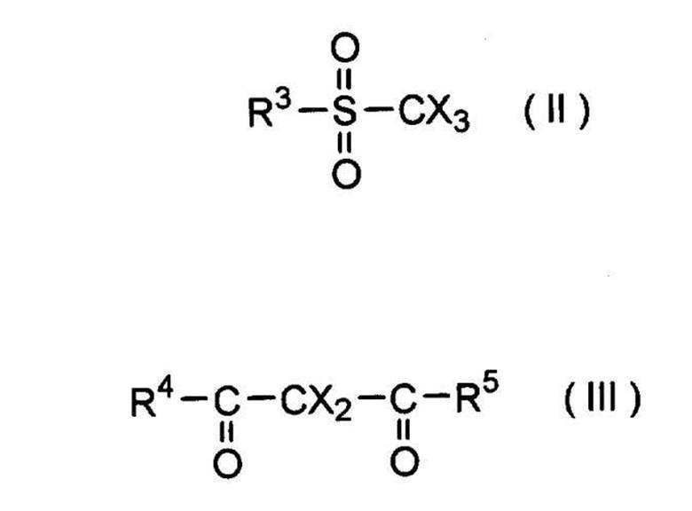
式(II)及び(III)において、Xは式(I)におけるものと同義であり、R3、R4及びR5はそれぞれ独立して、炭素原子数1~20までの1価の炭化水素基を表す。
ここで、R3、R4及びR5は、アリール基であることが好ましく、アリール基がアミド基で置換されているものは、感度と保存性のバランスに優れるためさらに好ましい。
下記式(II)及び(III)で表される化合物の中でも、式(IV)で表される化合物が特に好ましい。
ここで、R3、R4及びR5は、アリール基であることが好ましく、アリール基がアミド基で置換されているものは、感度と保存性のバランスに優れるためさらに好ましい。
下記式(II)及び(III)で表される化合物の中でも、式(IV)で表される化合物が特に好ましい。
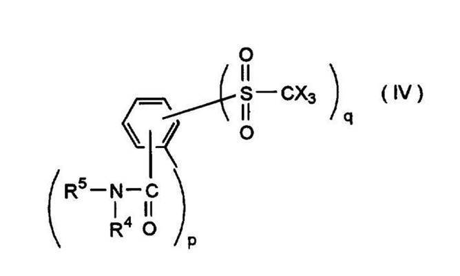
式(IV)において、R4及びR5はそれぞれ独立して、水素原子又は炭素原子数1~20までの1価の炭化水素基を表す。p及びqは1から5までの整数を表す。ただし、p+q=2~6である。
上記式(I)で表される電子受容型重合開始剤の具体例としては、下記式に示す化合物などが挙げられるが、本開示はこれらに限定されるものではない。
上記式(I)で表される電子受容型重合開始剤の具体例としては、下記式に示す化合物などが挙げられるが、本開示はこれらに限定されるものではない。
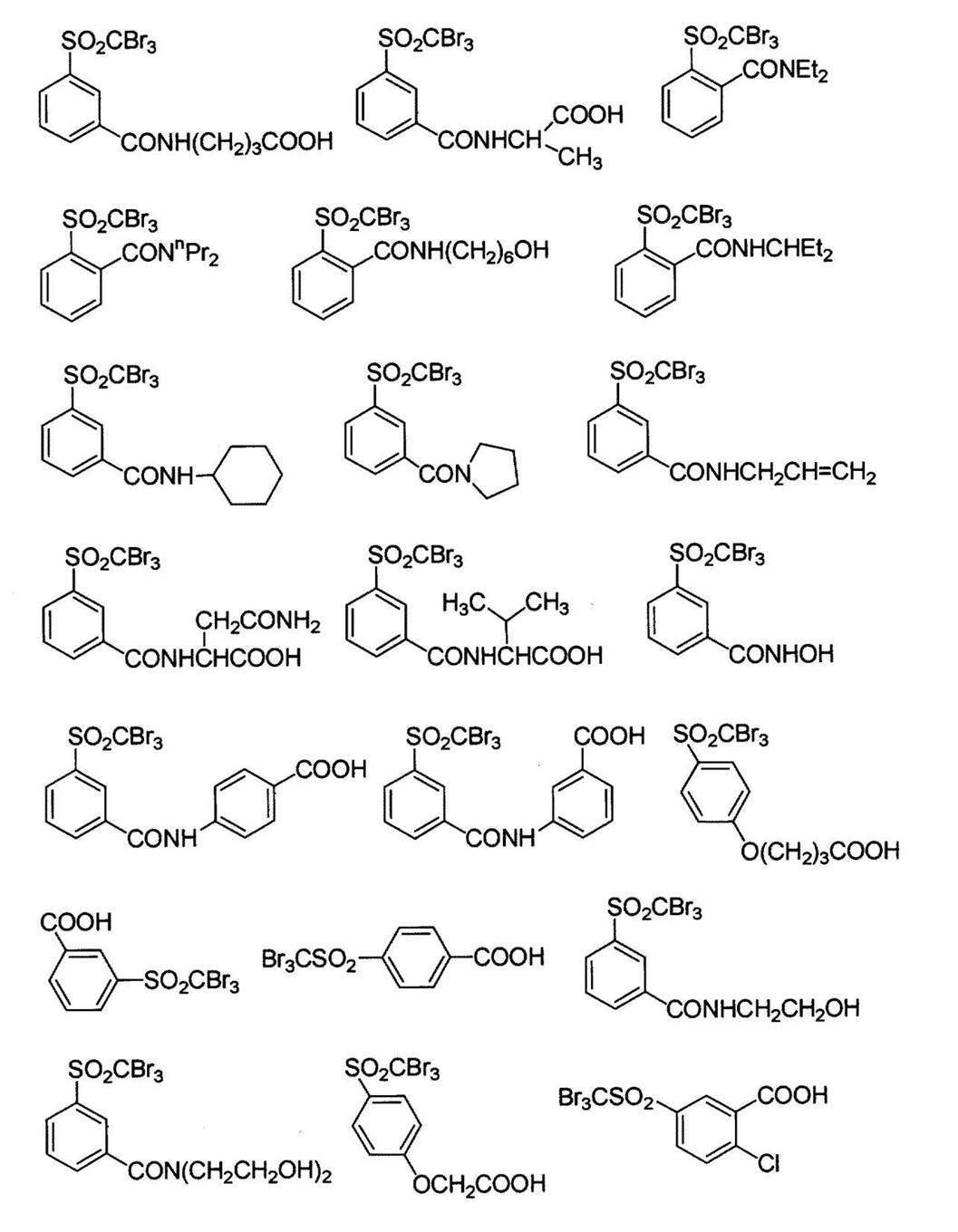
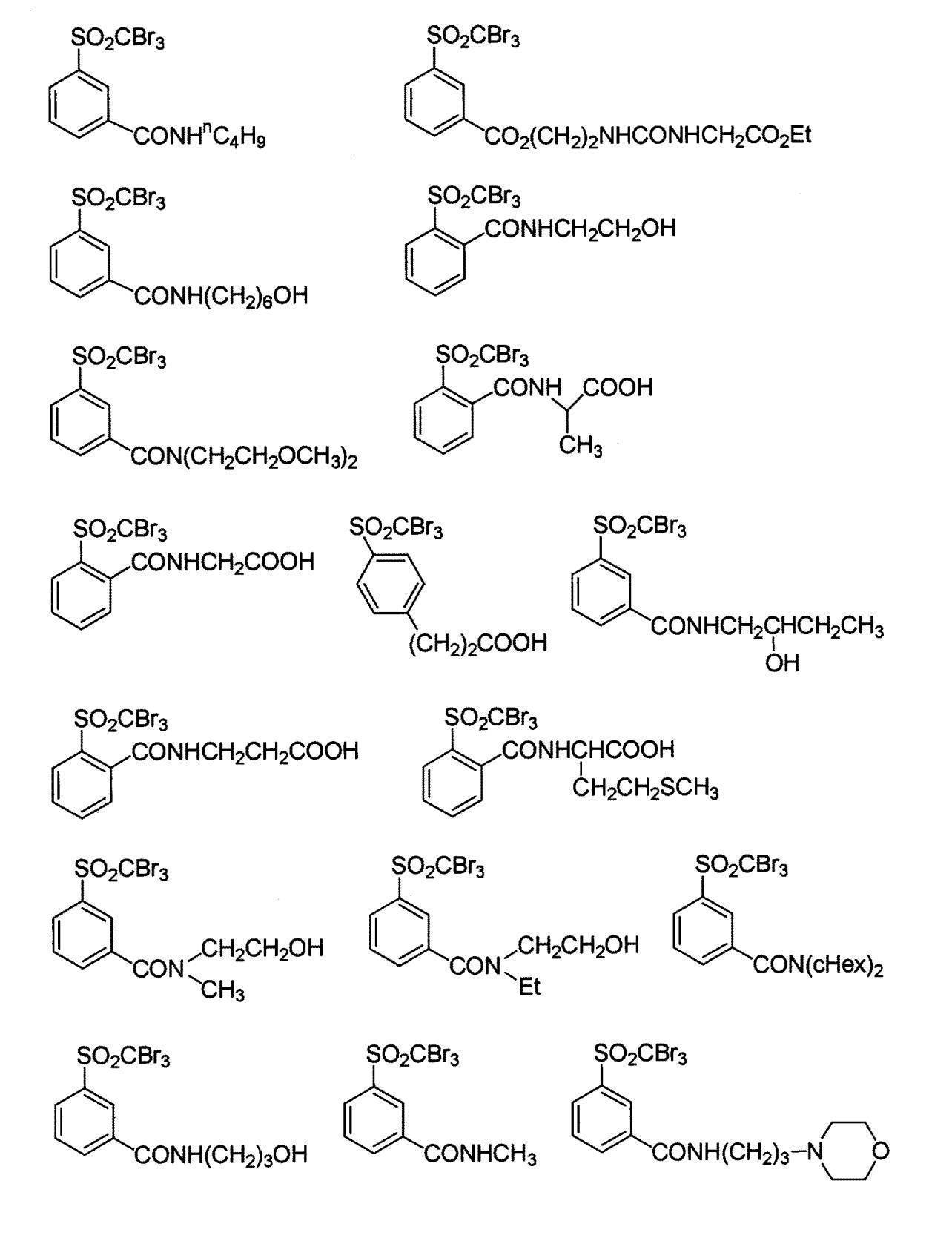
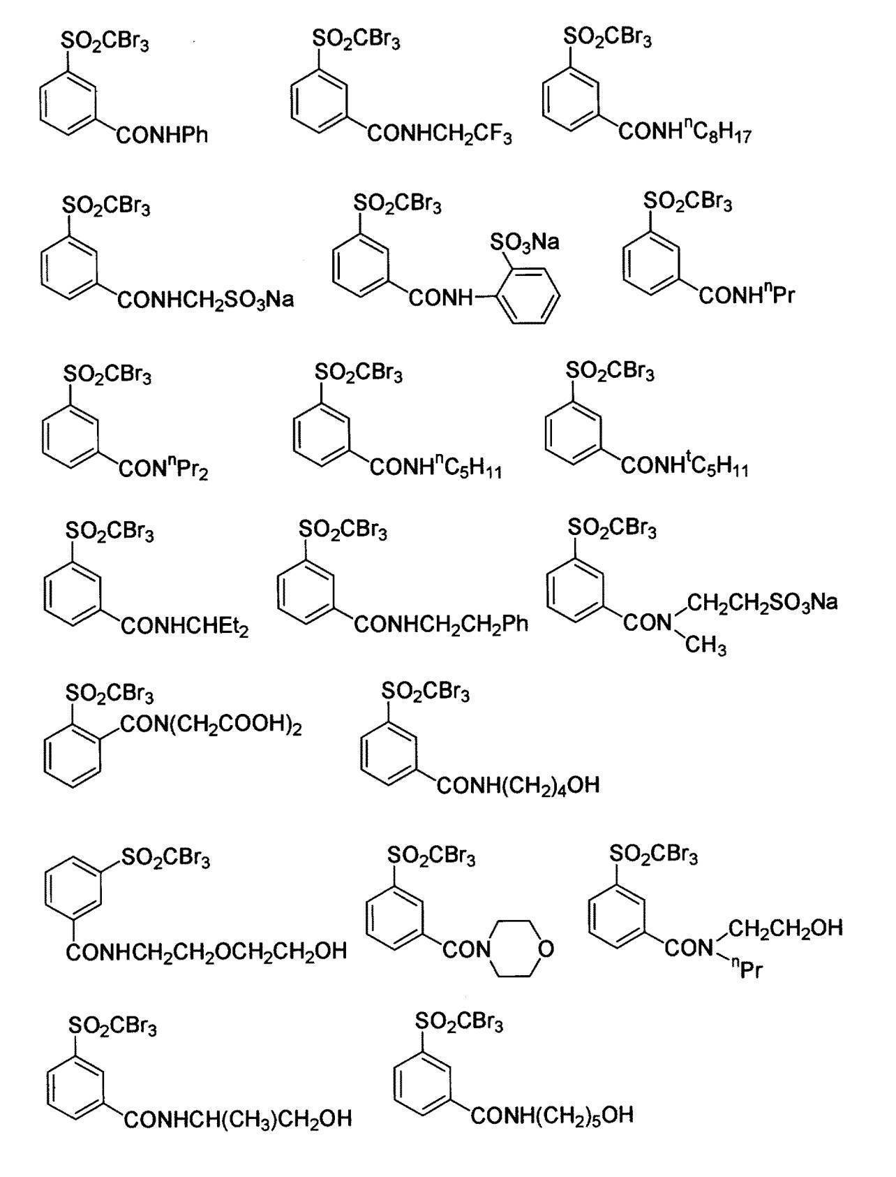

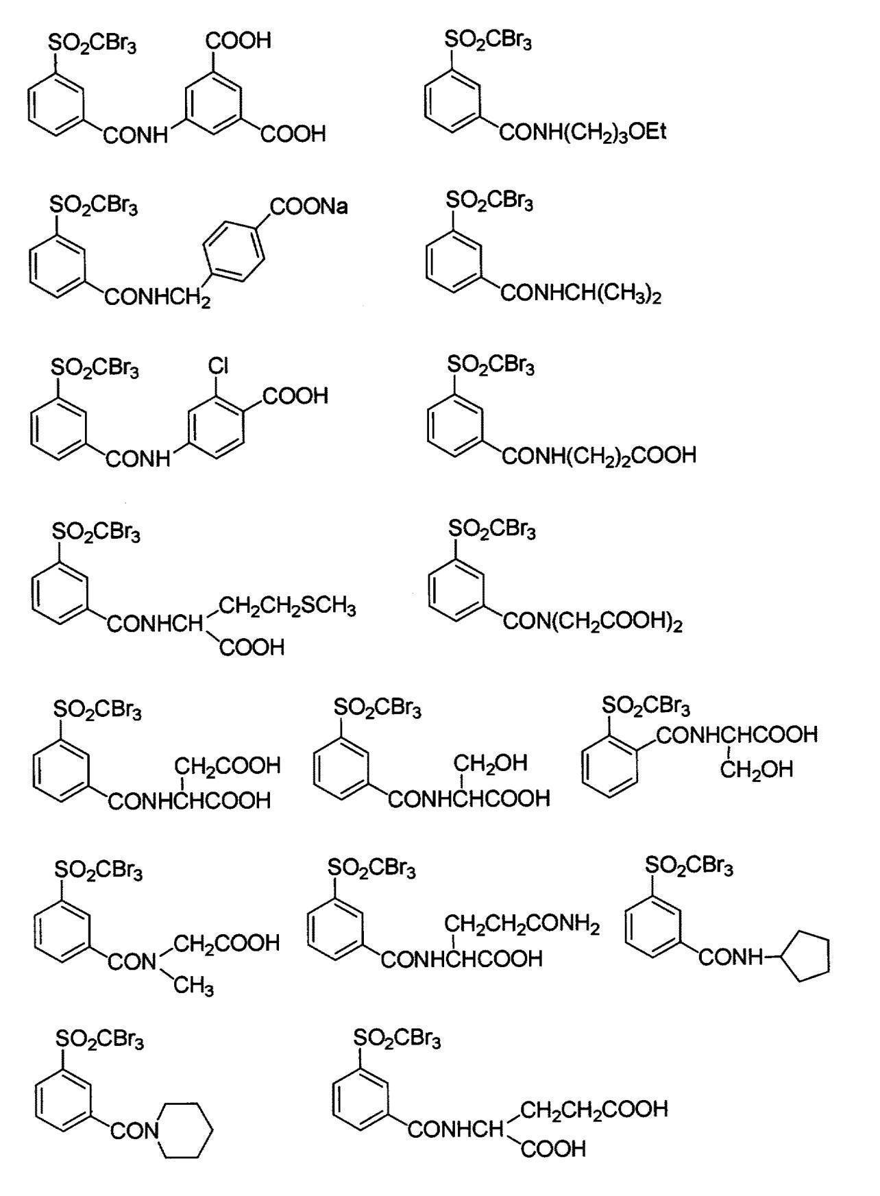


電子受容型重合開始剤の最低空軌道(LUMO)は、耐薬品性及びUV耐刷性の観点から、-3.00eV以下であることが好ましく、-3.02eV以下であることがより好ましい。
また、下限としては、-3.80eV以上であることが好ましく、-3.60eV以上であることがより好ましい。
また、下限としては、-3.80eV以上であることが好ましく、-3.60eV以上であることがより好ましい。
電子受容型重合開始剤の含有量は、画像記録層の全質量に対して、0.1質量%~50質量%であることが好ましく、0.5質量%~30質量%であることがより好ましく、0.8質量%~20質量%であることが特に好ましい。
〔電子供与型重合開始剤〕
重合開始剤は、平版印刷版における耐薬品性、及び、UV耐刷性の向上に寄与する観点から、電子供与型重合開始剤を更に含むことが好ましく、電子供与型重合開始剤及び上記電子供与型重合開始剤の両方を含むことがより好ましい。
電子供与型重合開始剤としては、例えば、以下の5種類が挙げられる。
(i)アルキル又はアリールアート錯体:酸化的に炭素-ヘテロ結合が解裂し、活性ラジカルを生成すると考えられる。具体的には、ボレート化合物等が挙げられる。
(ii)アミノ酢酸化合物:酸化により窒素に隣接した炭素上のC-X結合が解裂し、活性ラジカルを生成するものと考えられる。Xとしては、水素原子、カルボキシ基、トリメチルシリル基又はベンジル基が好ましい。具体的には、N-フェニルグリシン類(フェニル基に置換基を有していてもよい。)、N-フェニルイミノジ酢酸(フェニル基に置換基を有していてもよい。)等が挙げられる。
(iii)含硫黄化合物:上述のアミノ酢酸化合物の窒素原子を硫黄原子に置き換えたものが、同様の作用により活性ラジカルを生成し得る。具体的には、フェニルチオ酢酸(フェニル基に置換基を有していてもよい。)等が挙げられる。
(iv)含錫化合物:上述のアミノ酢酸化合物の窒素原子を錫原子に置き換えたものが、同様の作用により活性ラジカルを生成し得る。
(v)スルフィン酸塩類:酸化により活性ラジカルを生成し得る。具体的は、アリールスルフィン酸ナトリウム等が挙げられる。
重合開始剤は、平版印刷版における耐薬品性、及び、UV耐刷性の向上に寄与する観点から、電子供与型重合開始剤を更に含むことが好ましく、電子供与型重合開始剤及び上記電子供与型重合開始剤の両方を含むことがより好ましい。
電子供与型重合開始剤としては、例えば、以下の5種類が挙げられる。
(i)アルキル又はアリールアート錯体:酸化的に炭素-ヘテロ結合が解裂し、活性ラジカルを生成すると考えられる。具体的には、ボレート化合物等が挙げられる。
(ii)アミノ酢酸化合物:酸化により窒素に隣接した炭素上のC-X結合が解裂し、活性ラジカルを生成するものと考えられる。Xとしては、水素原子、カルボキシ基、トリメチルシリル基又はベンジル基が好ましい。具体的には、N-フェニルグリシン類(フェニル基に置換基を有していてもよい。)、N-フェニルイミノジ酢酸(フェニル基に置換基を有していてもよい。)等が挙げられる。
(iii)含硫黄化合物:上述のアミノ酢酸化合物の窒素原子を硫黄原子に置き換えたものが、同様の作用により活性ラジカルを生成し得る。具体的には、フェニルチオ酢酸(フェニル基に置換基を有していてもよい。)等が挙げられる。
(iv)含錫化合物:上述のアミノ酢酸化合物の窒素原子を錫原子に置き換えたものが、同様の作用により活性ラジカルを生成し得る。
(v)スルフィン酸塩類:酸化により活性ラジカルを生成し得る。具体的は、アリールスルフィン酸ナトリウム等が挙げられる。
これら電子供与型重合開始剤の中でも、画像記録層は、ボレート化合物を含有することが好ましい。ボレート化合物としては、テトラアリールボレート化合物又はモノアルキルトリアリールボレート化合物が好ましく、化合物の安定性の観点から、テトラアリールボレート化合物がより好ましく、テトラフェニルボレート化合物が特に好ましい。
ボレート化合物が有する対カチオンとしては、特に制限はないが、アルカリ金属イオン、又は、テトラアルキルアンモニウムイオンであることが好ましく、ナトリウムイオン、カリウムイオン、又は、テトラブチルアンモニウムイオンであることがより好ましい。
ボレート化合物が有する対カチオンとしては、特に制限はないが、アルカリ金属イオン、又は、テトラアルキルアンモニウムイオンであることが好ましく、ナトリウムイオン、カリウムイオン、又は、テトラブチルアンモニウムイオンであることがより好ましい。
ボレート化合物として具体的には、ナトリウムテトラフェニルボレートが好ましく挙げられる。
また、本開示に用いられる電子供与型重合開始剤の最高被占軌道(HOMO)は、耐薬品性及びUV耐刷性の観点から、-6.00eV以上であることが好ましく、-5.95eV以上であることがより好ましく、-5.93eV以上であることが更に好ましい。
また、上限としては、-5.00eV以下であることが好ましく、-5.40eV以下であることがより好ましい。
また、上限としては、-5.00eV以下であることが好ましく、-5.40eV以下であることがより好ましい。
本開示において、最高被占軌道(HOMO)及び最低空軌道(LUMO)の計算は、以下の方法により行う。
まず、計算対象となる化合物における対アニオンは無視する。
量子化学計算ソフトウェアGaussian09を用い、構造最適化はDFT(B3L
YP/6-31G(d))で行う。
MO(分子軌道)エネルギー計算は、上記構造最適化で得た構造でDFT(B3LYP/6-31+G(d,p)/CPCM(solvent=methanol))で行う。
上記MOエネルギー計算で得られたMOエネルギーEbare(単位:hartree)を以下の公式により、本開示においてHOMO及びLUMOの値として用いるEscaled(単位:eV)へ変換する。
Escaled=0.823168×27.2114×Ebare-1.07634
なお、27.2114は単にhartreeをeVに変換するための係数であり、0.823168と-1.07634とは調節係数であり、計算対象となる化合物のHOMOとLUMOとを計算が実測の値に合うように定める。
まず、計算対象となる化合物における対アニオンは無視する。
量子化学計算ソフトウェアGaussian09を用い、構造最適化はDFT(B3L
YP/6-31G(d))で行う。
MO(分子軌道)エネルギー計算は、上記構造最適化で得た構造でDFT(B3LYP/6-31+G(d,p)/CPCM(solvent=methanol))で行う。
上記MOエネルギー計算で得られたMOエネルギーEbare(単位:hartree)を以下の公式により、本開示においてHOMO及びLUMOの値として用いるEscaled(単位:eV)へ変換する。
Escaled=0.823168×27.2114×Ebare-1.07634
なお、27.2114は単にhartreeをeVに変換するための係数であり、0.823168と-1.07634とは調節係数であり、計算対象となる化合物のHOMOとLUMOとを計算が実測の値に合うように定める。
以下に電子供与型重合開始剤の好ましい具体例として、B-1~B-8及び他の化合物を示すが、これらに限定されないことは、言うまでもない。また、下記化学式において、Buはn-ブチル基を表し、Zは対カチオンを表す。
Z+で表される対カチオンとしては、Na+、K+、N+(Bu)4等が挙げられる。上記Buはn-ブチル基を表す。
また、Z+で表される対カチオンとしては、上記電子受容型重合開始剤におけるオニウムイオンも好適にあげられる。
Z+で表される対カチオンとしては、Na+、K+、N+(Bu)4等が挙げられる。上記Buはn-ブチル基を表す。
また、Z+で表される対カチオンとしては、上記電子受容型重合開始剤におけるオニウムイオンも好適にあげられる。
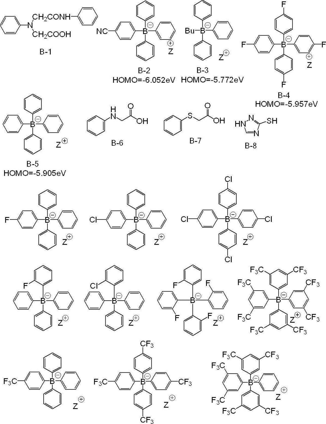

電子供与型重合開始剤は、1種のみを添加しても、2種以上を併用してもよい。
電子供与型重合開始剤の含有量は、画像記録層の全質量に対し、0.01質量%~30質量%が好ましく、0.05質量%~25質量%がより好ましく、0.1質量%~20質量%が更に好ましい。
電子供与型重合開始剤の含有量は、画像記録層の全質量に対し、0.01質量%~30質量%が好ましく、0.05質量%~25質量%がより好ましく、0.1質量%~20質量%が更に好ましい。
また、本開示における好ましい態様の一つは、上記電子受容型重合開始剤と、上記電子供与型重合開始剤と、が塩を形成している態様である。
具体的には、例えば、上記オニウム化合物が、オニウムイオンと、上記電子供与型重合開始剤におけるアニオン(例えば、テトラフェニルボレートアニオン)との塩である態様が挙げられる。また、より好ましくは、上記ヨードニウム塩化合物におけるヨードニウムカチオン(例えば、ジ-p-トリルヨードニウムカチオン)と、上記電子供与型重合開始剤におけるボレートアニオンとが塩を形成した、ヨードニウムボレート化合物が挙げられる。
上記電子受容型重合開始剤と上記電子供与型重合開始剤とが塩を形成している態様の具体例を以下に示すが、本開示はこれらに限定されるものではない。
具体的には、例えば、上記オニウム化合物が、オニウムイオンと、上記電子供与型重合開始剤におけるアニオン(例えば、テトラフェニルボレートアニオン)との塩である態様が挙げられる。また、より好ましくは、上記ヨードニウム塩化合物におけるヨードニウムカチオン(例えば、ジ-p-トリルヨードニウムカチオン)と、上記電子供与型重合開始剤におけるボレートアニオンとが塩を形成した、ヨードニウムボレート化合物が挙げられる。
上記電子受容型重合開始剤と上記電子供与型重合開始剤とが塩を形成している態様の具体例を以下に示すが、本開示はこれらに限定されるものではない。
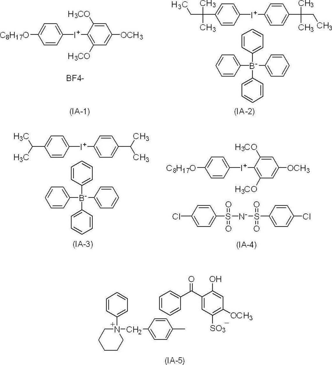
本開示において、画像記録層が、オニウムイオンと、上述の電子供与型重合開始剤におけるアニオンと、を含む場合、画像記録層は電子受容型重合開始剤及び上記電子供与型重合開始剤を含むものとする。
〔赤外線吸収剤〕
上記画像記録層は、赤外線吸収剤を含む。
赤外線吸収剤としては、特に制限はなく、例えば、顔料及び染料が挙げられる。
赤外線吸収剤として用いられる染料としては、市販の染料及び例えば、「染料便覧」(有機合成化学協会編集、昭和45年刊)等の文献に記載されている公知のものが利用できる。具体的には、アゾ染料、金属錯塩アゾ染料、ピラゾロンアゾ染料、ナフトキノン染料、アントラキノン染料、フタロシアニン染料、カルボニウム染料、キノンイミン染料、メチン染料、シアニン染料、スクアリリウム色素、ピリリウム塩、金属チオレート錯体等の染料が挙げられる。
上記画像記録層は、赤外線吸収剤を含む。
赤外線吸収剤としては、特に制限はなく、例えば、顔料及び染料が挙げられる。
赤外線吸収剤として用いられる染料としては、市販の染料及び例えば、「染料便覧」(有機合成化学協会編集、昭和45年刊)等の文献に記載されている公知のものが利用できる。具体的には、アゾ染料、金属錯塩アゾ染料、ピラゾロンアゾ染料、ナフトキノン染料、アントラキノン染料、フタロシアニン染料、カルボニウム染料、キノンイミン染料、メチン染料、シアニン染料、スクアリリウム色素、ピリリウム塩、金属チオレート錯体等の染料が挙げられる。
これらの染料のうち特に好ましいものとしては、シアニン色素、スクアリリウム色素、ピリリウム塩、ニッケルチオレート錯体、インドレニンシアニン色素が挙げられる。更に、シアニン色素やインドレニンシアニン色素が挙げられる。中でも、シアニン色素が特に好ましい。
上記赤外線吸収剤としては、メソ位に酸素又は窒素原子を有するカチオン性のポリメチン色素であることが好ましい。カチオン性のポリメチン色素としては、シアニン色素、ピリリウム色素、チオピリリウム色素、アズレニウム色素等が好ましく挙げられ、入手の容易性、導入反応時の溶剤溶解性等の観点から、シアニン色素であることが好ましい。
シアニン色素の具体例としては、特開2001-133969号公報の段落0017~0019に記載の化合物、特開2002-023360号公報の段落0016~0021、特開2002-040638号公報の段落0012~0037に記載の化合物、好ましくは特開2002-278057号公報の段落0034~0041、特開2008-195018号公報の段落0080~0086に記載の化合物、特に好ましくは特開2007-90850号公報の段落0035~0043に記載の化合物、特開2012-206495号公報の段落0105~0113に記載の化合物が挙げられる。
また、特開平5-5005号公報の段落0008~0009、特開2001-222101号公報の段落0022~0025に記載の化合物も好ましく使用することができる。
顔料としては、特開2008-195018号公報の段落0072~0076に記載の化合物が好ましい。
また、特開平5-5005号公報の段落0008~0009、特開2001-222101号公報の段落0022~0025に記載の化合物も好ましく使用することができる。
顔料としては、特開2008-195018号公報の段落0072~0076に記載の化合物が好ましい。
また、上記赤外線吸収剤が、分解性赤外線吸収剤であることが好ましい。
上記赤外線吸収剤として、分解性赤外線吸収剤色素を用いることにより、上記赤外線吸収剤又はその分解物が重合を促進し、また、上記熱可塑性樹脂を用いることにより極性の高い膜を得ることができ、更に、上記赤外線吸収剤の分解物と上記重合性化合物とが相互作用することにより、UV耐刷性に優れると推定している。
上記分解性赤外線吸収剤は、赤外線露光により、赤外線を吸収し、分解して、発色する機能を有する赤外線吸収剤であることが好ましい。ここで、「発色」とは、赤外線露光前は可視光領域(400nm以上750nm未満の波長域)にほとんど吸収がないが、赤外線露光により可視光領域に吸収を生じることを意味し、可視光領域よりも低波長領域の吸収が可視光領域に長波長化することも包含する。
以降、分解性赤外線吸収剤が、赤外線露光により、赤外線を吸収し、分解して形成される発色した化合物を、「分解性赤外線吸収剤の発色体」ともいう。
また、分解性赤外線吸収剤は、赤外線露光により、赤外線を吸収し、吸収した赤外線を熱に変換する機能を有することが好ましい。
上記分解性赤外線吸収剤は、赤外線波長域(波長750nm~1mm)の少なくとも1部の光を吸収し、分解するものであればよいが、750nm~1,400nmの波長域に極大吸収を有する赤外線吸収剤であることが好ましい。
上記赤外線吸収剤として、分解性赤外線吸収剤色素を用いることにより、上記赤外線吸収剤又はその分解物が重合を促進し、また、上記熱可塑性樹脂を用いることにより極性の高い膜を得ることができ、更に、上記赤外線吸収剤の分解物と上記重合性化合物とが相互作用することにより、UV耐刷性に優れると推定している。
上記分解性赤外線吸収剤は、赤外線露光により、赤外線を吸収し、分解して、発色する機能を有する赤外線吸収剤であることが好ましい。ここで、「発色」とは、赤外線露光前は可視光領域(400nm以上750nm未満の波長域)にほとんど吸収がないが、赤外線露光により可視光領域に吸収を生じることを意味し、可視光領域よりも低波長領域の吸収が可視光領域に長波長化することも包含する。
以降、分解性赤外線吸収剤が、赤外線露光により、赤外線を吸収し、分解して形成される発色した化合物を、「分解性赤外線吸収剤の発色体」ともいう。
また、分解性赤外線吸収剤は、赤外線露光により、赤外線を吸収し、吸収した赤外線を熱に変換する機能を有することが好ましい。
上記分解性赤外線吸収剤は、赤外線波長域(波長750nm~1mm)の少なくとも1部の光を吸収し、分解するものであればよいが、750nm~1,400nmの波長域に極大吸収を有する赤外線吸収剤であることが好ましい。
上記分解性赤外線吸収剤は、赤外線露光に起因する熱、電子移動又はその両方により分解する赤外線吸収剤であることが好ましく、赤外線露光に起因する電子移動により分解する赤外線吸収剤であることがより好ましい。ここで、「電子移動により分解する」とは、赤外線露光によって分解性赤外線吸収剤のHOMO(最高被占軌道)からLUMO(最低空軌道)に励起した電子が、分子内の電子受容基(LUMOと電位が近い基)に分子内電子移動し、それに伴って分解が生じることを意味する。
上記分解性赤外線吸収剤としては、発色性、及び、得られる平版印刷版のUV耐刷性の観点から、赤外線露光により分解する、シアニン色素が好ましい。
上記赤外線吸収剤としては、発色性、及び、得られる平版印刷版のUV耐刷性の観点から、下記式1-1で表される化合物であることがより好ましい。
上記赤外線吸収剤としては、発色性、及び、得られる平版印刷版のUV耐刷性の観点から、下記式1-1で表される化合物であることがより好ましい。
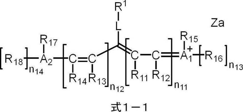
式1-1中、R1は赤外線露光によりR1-L結合が開裂する基を表し、R11~R18はそれぞれ独立に、水素原子、ハロゲン原子、-Ra、-ORb、-SRc又は-NRdReを表し、Ra~Reはそれぞれ独立に、炭化水素基を表し、A1、A2及び複数のR11~R18が連結して単環又は多環を形成してもよく、A1及びA2はそれぞれ独立に、酸素原子、硫黄原子又は窒素原子を表し、n11及びn12はそれぞれ独立に、0~5の整数を表し、但し、n11及びn12の合計は2以上であり、n13及びn14はそれぞれ独立に、0又は1を表し、Lは酸素原子、硫黄原子又は-NR10-を表し、R10は水素原子、アルキル基又はアリール基を表し、Zaは電荷を中和する対イオンを表す。
式1-1で表されるシアニン色素は、赤外線で露光されると、R1-L結合が開裂し、Lは、=O、=S又は=NR10となって、分解性赤外線吸収剤の発色体が形成される。R1は離脱して、ラジカル体又はイオン体を形成する。これらは、画像記録層に含まれる重合性を有する化合物の重合に寄与する。
式1-1において、R11~R18は、それぞれ独立に、水素原子、-Ra、-ORb、-SRc又は-NRdReが好ましい。
Ra~Reにおける炭化水素基は、炭素数1~30の炭化水素基が好ましく、炭素数1~15の炭化水素基がより好ましく、炭素数1~10の炭化水素基が更に好ましい。上記炭化水素基は、直鎖状であっても、分岐を有していても、環構造を有していてもよい。
Ra~Reにおける炭化水素基は、炭素数1~30の炭化水素基が好ましく、炭素数1~15の炭化水素基がより好ましく、炭素数1~10の炭化水素基が更に好ましい。上記炭化水素基は、直鎖状であっても、分岐を有していても、環構造を有していてもよい。
式1-1におけるR11~R14はそれぞれ独立に、水素原子又は炭化水素基が好ましく、水素原子又はアルキル基がより好ましく、水素原子が更に好ましい。
また、Lが結合する炭素原子と結合する炭素原子に結合するR11及びR13は、アルキル基が好ましく、両者が連結して環を形成することがより好ましい。上記形成される環は5員環又は6員環が好ましく、5員環がより好ましい。
A1 +が結合する炭素原子に結合するR12及びA2が結合する炭素原子に結合するR14は、それぞれ、R15及びR17と連結して環を形成することが好ましい。
また、Lが結合する炭素原子と結合する炭素原子に結合するR11及びR13は、アルキル基が好ましく、両者が連結して環を形成することがより好ましい。上記形成される環は5員環又は6員環が好ましく、5員環がより好ましい。
A1 +が結合する炭素原子に結合するR12及びA2が結合する炭素原子に結合するR14は、それぞれ、R15及びR17と連結して環を形成することが好ましい。
式1-1におけるR15は、炭化水素基が好ましい。また、R15と、A1
+が結合する炭素原子に結合するR12とが連結して環を形成することが好ましい。形成される環としては、インドリウム環、ピリリウム環、チオピリリウム環、ベンゾオキサゾリン環又はベンゾイミダゾリン環が好ましく、発色性の観点から、インドリウム環がより好ましい。
式1-1におけるR17は、炭化水素基が好ましい。また、R17と、A2が結合する炭素原子に結合するR14とが連結して環を形成することが好ましい。形成される環としては、インドール環、ピラン環、チオピラン環、ベンゾオキサゾール環、又は、ベンゾイミダゾール環が好ましく、発色性の観点から、インドール環がより好ましい。
式1-1におけるR15及びR17は同一の基であることが好ましく、それぞれが環を形成する場合、同一の環を形成することが好ましい。
式1-1におけるR17は、炭化水素基が好ましい。また、R17と、A2が結合する炭素原子に結合するR14とが連結して環を形成することが好ましい。形成される環としては、インドール環、ピラン環、チオピラン環、ベンゾオキサゾール環、又は、ベンゾイミダゾール環が好ましく、発色性の観点から、インドール環がより好ましい。
式1-1におけるR15及びR17は同一の基であることが好ましく、それぞれが環を形成する場合、同一の環を形成することが好ましい。
式1-1におけるR16及びR18は同一の基であることが好ましい。
更に、式1-1により表される化合物の水溶性を向上させる観点から、R16及びR18はそれぞれ独立に、(ポリ)オキシアルキレン基を有するアルキル基又はアニオン構造を有するアルキル基が好ましく、アルコキシアルキル基、カルボキシレート基又はスルホネート基を有するアルキル基がより好ましく、末端にスルホネート基を有するアルキル基が更に好ましい。上記アルキル基としては、炭素数1~10のアルキル基が好ましく、炭素数1~4のアルキル基がより好ましい。
上記アニオン構造の対カチオンは、式1-1中のR1-Lに含まれうるカチオン又はA1 +であってもよいし、アルカリ金属カチオンやアルカリ土類金属カチオンであってもよい。
上記スルホネート基の対カチオンは、式1-1中のR1-Lに含まれうるカチオン又はA1 +であってもよいし、アルカリ金属カチオンやアルカリ土類金属カチオンであってもよい。
また、式1-1により表される化合物の極大吸収波長を長波長化し、また、発色性及び平版印刷版における耐刷性の観点から、R16及びR18はそれぞれ独立に、アルキル基又は芳香環を有するアルキル基が好ましい。上記アルキル基としては、炭素数1~10のアルキル基が好ましく、炭素数1~4のアルキル基がより好ましく、メチル基又はエチル基が更に好ましい。芳香環を有するアルキル基としては、末端に芳香環を有するアルキル基が好ましく、2-フェニルエチル基、2-ナフタレニルエチル基又は2-(9-アントラセニル)エチル基がより好ましい。
更に、式1-1により表される化合物の水溶性を向上させる観点から、R16及びR18はそれぞれ独立に、(ポリ)オキシアルキレン基を有するアルキル基又はアニオン構造を有するアルキル基が好ましく、アルコキシアルキル基、カルボキシレート基又はスルホネート基を有するアルキル基がより好ましく、末端にスルホネート基を有するアルキル基が更に好ましい。上記アルキル基としては、炭素数1~10のアルキル基が好ましく、炭素数1~4のアルキル基がより好ましい。
上記アニオン構造の対カチオンは、式1-1中のR1-Lに含まれうるカチオン又はA1 +であってもよいし、アルカリ金属カチオンやアルカリ土類金属カチオンであってもよい。
上記スルホネート基の対カチオンは、式1-1中のR1-Lに含まれうるカチオン又はA1 +であってもよいし、アルカリ金属カチオンやアルカリ土類金属カチオンであってもよい。
また、式1-1により表される化合物の極大吸収波長を長波長化し、また、発色性及び平版印刷版における耐刷性の観点から、R16及びR18はそれぞれ独立に、アルキル基又は芳香環を有するアルキル基が好ましい。上記アルキル基としては、炭素数1~10のアルキル基が好ましく、炭素数1~4のアルキル基がより好ましく、メチル基又はエチル基が更に好ましい。芳香環を有するアルキル基としては、末端に芳香環を有するアルキル基が好ましく、2-フェニルエチル基、2-ナフタレニルエチル基又は2-(9-アントラセニル)エチル基がより好ましい。
式1-1におけるn11及びn12は同一の0~5の整数が好ましく、1~3の整数がより好ましく、1又は2が更に好ましく、2が特に好ましい。
式1-1におけるA1及びA2は、それぞれ独立に、酸素原子、硫黄原子又は窒素原子を表し、窒素原子が好ましい。
式1-1におけるA1及びA2は同一の原子であることが好ましい。
式1-1におけるA1及びA2は同一の原子であることが好ましい。
式1-1におけるZaは、電荷を中和する対イオンを表す。アニオン種を表す場合は、スルホネートイオン、カルボキシレートイオン、テトラフルオロボレートイオン、ヘキサフルオロホスフェートイオン、p-トルエンスルホネートイオン、過塩素酸塩イオン等が挙げられ、ヘキサフルオロホスフェートイオンが好ましい。カチオン種を表す場合は、アルカリ金属イオン、アルカリ土類金属イオン、アンモニウムイオン、ピリジニウムイオン、スルホニウムイオン等が挙げられ、ナトリウムイオン、カリウムイオン、アンモニウムイオン、ピリジニウムイオン又はスルホニウムイオンが好ましく、ナトリウムイオン、カリウムイオン又はアンモニウムイオンがより好ましい。
R11~R18及びR1-Lは、アニオン構造やカチオン構造を有していてもよく、R11~R18及びR1-Lの全てが電荷的に中性の基であれば、Zaは一価の対アニオンであるが、例えば、R11~R18及びR1-Lに2以上のアニオン構造を有する場合、Zaは対カチオンにもなり得る。
また、式1-1で表されるシアニン色素が、化合物の全体において電荷的に中性な構造であれば、Zaは存在しない。
R11~R18及びR1-Lは、アニオン構造やカチオン構造を有していてもよく、R11~R18及びR1-Lの全てが電荷的に中性の基であれば、Zaは一価の対アニオンであるが、例えば、R11~R18及びR1-Lに2以上のアニオン構造を有する場合、Zaは対カチオンにもなり得る。
また、式1-1で表されるシアニン色素が、化合物の全体において電荷的に中性な構造であれば、Zaは存在しない。
式1-1において、R1で表される赤外線露光によりR1-L結合が開裂する基については、後で詳細に記載する。
上記分解性赤外線吸収剤としては、発色性、及び、得られる平版印刷版のUV耐刷性の観点から、下記式1-Aで表されるシアニン色素がより好ましい。
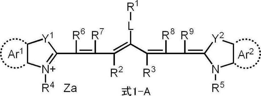
式1-A中、R1は赤外線露光によりR1-L結合が開裂する基を表し、R2及びR3はそれぞれ独立に、水素原子又はアルキル基を表し、R2及びR3が互いに連結して環を形成してもよく、Ar1及びAr2はそれぞれ独立に、ベンゼン環又はナフタレン環を形成する基を表し、Y1及びY2はそれぞれ独立に、酸素原子、硫黄原子、-NR0-又はジアルキルメチレン基を表し、R0は水素原子、アルキル基又はアリール基を表し、R4及びR5はそれぞれ独立に、アルキル基、-CO2M基又は-PO3M2基を表し、Mは水素原子、Na原子、K原子又はオニウム基を表し、R6~R9はそれぞれ独立に、水素原子又はアルキル基を表し、Lは酸素原子、硫黄原子又は-NR10-を表し、R10は水素原子、アルキル基又はアリール基を表し、Zaは電荷を中和する対イオンを表す。
式1-Aにおいて、R2~R9及びR0におけるアルキル基は、炭素数1~30のアルキル基が好ましく、炭素数1~15のアルキル基がより好ましく、炭素数1~10のアルキル基が更に好ましい。上記アルキル基は、直鎖状であっても、分岐を有していても、環構造を有していてもよい。
具体的には、例えば、メチル基、エチル基、プロピル基、ブチル基、ペンチル基、ヘキシル基、ヘプチル基、オクチル基、ノニル基、デシル基、ウンデシル基、ドデシル基、トリデシル基、ヘキサデシル基、オクタデシル基、エイコシル基、イソプロピル基、イソブチル基、s-ブチル基、tert-ブチル基、イソペンチル基、ネオペンチル基、1-メチルブチル基、イソヘキシル基、2-エチルヘキシル基、2-メチルヘキシル基、シクロヘキシル基、シクロペンチル基、及び、2-ノルボルニル基が挙げられる。
アルキル基の中で、メチル基、エチル基、プロピル基又はブチル基が好ましい。
具体的には、例えば、メチル基、エチル基、プロピル基、ブチル基、ペンチル基、ヘキシル基、ヘプチル基、オクチル基、ノニル基、デシル基、ウンデシル基、ドデシル基、トリデシル基、ヘキサデシル基、オクタデシル基、エイコシル基、イソプロピル基、イソブチル基、s-ブチル基、tert-ブチル基、イソペンチル基、ネオペンチル基、1-メチルブチル基、イソヘキシル基、2-エチルヘキシル基、2-メチルヘキシル基、シクロヘキシル基、シクロペンチル基、及び、2-ノルボルニル基が挙げられる。
アルキル基の中で、メチル基、エチル基、プロピル基又はブチル基が好ましい。
上記アルキル基は、置換基を有していてもよい。置換基の例としては、アルコキシ基、アリーロキシ基、アミノ基、アルキルチオ基、アリールチオ基、ハロゲン原子、カルボキシ基、カルボキシレート基、スルホ基、スルホネート基、アルキルオキシカルボニル基、アリールオキシカルボニル基、及び、これらを組み合わせた基等が挙げられる。
R0におけるアリール基は、炭素数6~30のアリール基が好ましく、炭素数6~20のアリール基がより好ましく、炭素数6~12のアリール基が更に好ましい。
上記アリール基は、置換基を有していてもよい。置換基の例としては、アルキル基、アルコキシ基、アリーロキシ基、アミノ基、アルキルチオ基、アリールチオ基、ハロゲン原子、カルボキシ基、カルボキシレート基、スルホ基、スルホネート基、アルキルオキシカルボニル基、アリールオキシカルボニル基、及び、これらを組み合わせた基等が挙げられる。
具体的には、例えば、フェニル基、ナフチル基、p-トリル基、p-クロロフェニル基、p-フルオロフェニル基、p-メトキシフェニル基、p-ジメチルアミノフェニル基、p-メチルチオフェニル基、p-フェニルチオフェニル基等が挙げられる。
アリール基の中で、フェニル基、p-メトキシフェニル基、p-ジメチルアミノフェニル基又はナフチル基が好ましい。
上記アリール基は、置換基を有していてもよい。置換基の例としては、アルキル基、アルコキシ基、アリーロキシ基、アミノ基、アルキルチオ基、アリールチオ基、ハロゲン原子、カルボキシ基、カルボキシレート基、スルホ基、スルホネート基、アルキルオキシカルボニル基、アリールオキシカルボニル基、及び、これらを組み合わせた基等が挙げられる。
具体的には、例えば、フェニル基、ナフチル基、p-トリル基、p-クロロフェニル基、p-フルオロフェニル基、p-メトキシフェニル基、p-ジメチルアミノフェニル基、p-メチルチオフェニル基、p-フェニルチオフェニル基等が挙げられる。
アリール基の中で、フェニル基、p-メトキシフェニル基、p-ジメチルアミノフェニル基又はナフチル基が好ましい。
R2及びR3は、連結して環を形成していることが好ましい。
R2及びR3が連結して環を形成する場合、5員環又は6員環が好ましく、5員環が特に好ましい。
R2及びR3が連結して環を形成する場合、5員環又は6員環が好ましく、5員環が特に好ましい。
Y1及びY2はそれぞれ独立に、酸素原子、硫黄原子、-NR0-又はジアルキルメチレン基を表し、-NR0-又はジアルキルメチレン基が好ましく、ジアルキルメチレン基がより好ましい。
R0は水素原子、アルキル基又はアリール基を表し、アルキル基が好ましい。
R0は水素原子、アルキル基又はアリール基を表し、アルキル基が好ましい。
R4又はR5で表されるアルキル基は、置換アルキルであってもよい。R4又はR5で表される置換アルキル基としては、下記式(a1)~式(a4)のいずれかで表される基が挙げられる。
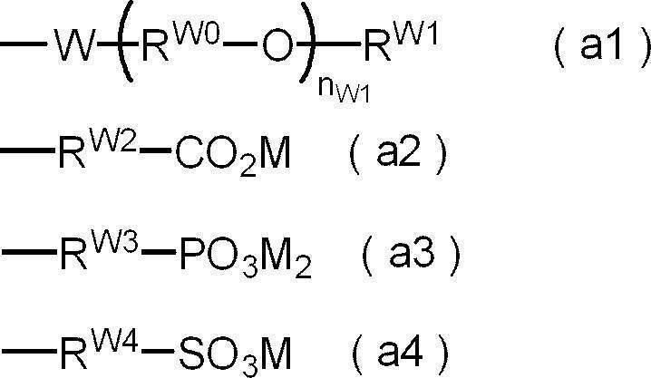
式(a1)~式(a4)中、RW0は炭素数2~6のアルキレン基を表し、Wは単結合又は酸素原子を表し、nW1は1~45の整数を表し、RW1は炭素数1~12のアルキル基又は-C(=O)-RW5を表し、RW5は炭素数1~12のアルキル基を表し、RW2~RW4はそれぞれ独立に、単結合又は炭素数1~12のアルキレン基を表し、Mは水素原子、Na原子、K原子又はオニウム基を表す。
式(a1)において、RW0で表されるアルキレン基の具体例としては、エチレン基、n-プロピレン基、イソプロピレン基、n-ブチレン基、イソブチレン基、n-ペンチレン基、イソペンチレン基、n-ヘキシル基、イソヘキシル基等が挙げられ、エチレン基、n-プロピレン基、イソプロピレン基、n-ブチレン基が好ましく、n-プロピレン基が特に好ましい。
nW1は1~10が好ましく、1~5がより好ましく、1~3が特に好ましい。
RW1で表されるアルキル基の具体例としては、メチル基、エチル基、n-プロピル基、イソプロピル基、n-ブチル基、イソブチル基、tert-ブチル基、n-ペンチル基、イソペンチル基、ネオペンチル基、n-ヘキシル基、n-オクチル基、n-ドデシル基等が挙げられ、メチル基、エチル基、n-プロピル基、イソプロピル基、n-ブチル基、tert-ブチル基が好ましく、メチル基、エチル基が更に好ましく、メチル基が特に好ましい。
RW5で表されるアルキル基は、RW1で表されるアルキル基と同様であり、好ましい態様もRW1で表されるアルキル基の好ましい態様と同様である。
nW1は1~10が好ましく、1~5がより好ましく、1~3が特に好ましい。
RW1で表されるアルキル基の具体例としては、メチル基、エチル基、n-プロピル基、イソプロピル基、n-ブチル基、イソブチル基、tert-ブチル基、n-ペンチル基、イソペンチル基、ネオペンチル基、n-ヘキシル基、n-オクチル基、n-ドデシル基等が挙げられ、メチル基、エチル基、n-プロピル基、イソプロピル基、n-ブチル基、tert-ブチル基が好ましく、メチル基、エチル基が更に好ましく、メチル基が特に好ましい。
RW5で表されるアルキル基は、RW1で表されるアルキル基と同様であり、好ましい態様もRW1で表されるアルキル基の好ましい態様と同様である。
式(a1)で表される基の具体例を以下に示すが、本開示はこれらに限定されるものではない。下記構造式中、Meはメチル基、Etはエチル基を表し、*は結合部位を表す。
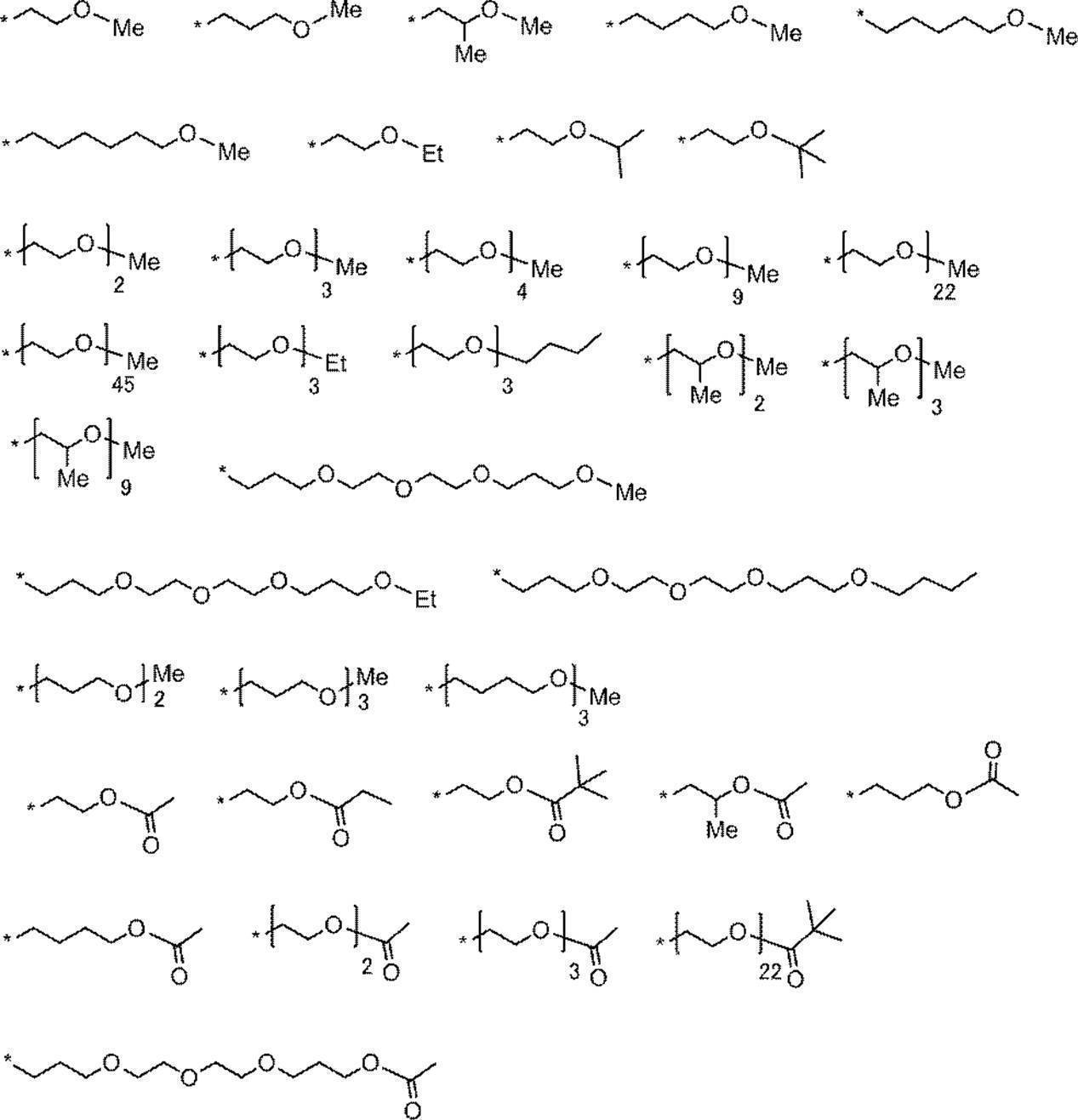
式(a2)~式(a4)において、RW2~RW4で表されるアルキレン基の具体例としては、メチレン基、エチレン基、n-プロピレン基、イソプロピレン基、n-ブチレン基、イソブチレン基、n-ペンチレン基、イソペンチレン基、n-ヘキシル基、イソヘキシル基、n-オクチレン基、n-ドデシレン基等が挙げられ、エチレン基、n-プロピレン基、イソプロピレン基、n-ブチレン基が好ましく、エチレン基、n-プロピレン基が特に好ましい。
式(a3)において、2つ存在するMは同じでも異なってもよい。
式(a3)において、2つ存在するMは同じでも異なってもよい。
式(a2)~式(a4)において、Mで表されるオニウム基としては、アンモニウム基、ヨードニウム基、ホスホニウム基、スルホニウム基等が挙げられる。
式(a1)~式(a4)で表される基の中で、式(a1)又は式(a4)で表される基が好ましい。
式1-Aにおいて、R4及びR5はそれぞれ無置換アルキル基であることが好ましい。R4及びR5は、同じ基であることが好ましい。
R6~R9はそれぞれ独立に、水素原子又はアルキル基を表し、水素原子が好ましい。
Ar1及びAr2はそれぞれ独立に、ベンゼン環又はナフタレン環を形成する基を表す。上記ベンゼン環及びナフタレン環は、置換基を有していてもよい。置換基としては、アルキル基、アルコキシ基、アリーロキシ基、アミノ基、アルキルチオ基、アリールチオ基、ハロゲン原子、カルボキシ基、カルボキシレート基、スルホ基、スルホネート基、アルキルオキシカルボニル基、アリールオキシカルボニル基、アシルオキシ基、ホスホン酸基、及び、これらを組み合わせた基等が挙げられる。置換基としては、アルキル基が好ましい。
また、式1-Aで表される化合物の極大吸収波長を長波長化し、また、発色性及び平版印刷版の耐刷性を向上させる観点から、Ar1及びAr2はそれぞれ独立に、ナフタレン環、又は、アルキル基もしくはアルコキシ基を置換基として有するベンゼン環を形成する基が好ましく、ナフタレン環、又は、アルコキシ基を置換基として有するベンゼン環を形成する基がより好ましく、ナフタレン環、又は、メトキシ基を置換基として有するベンゼン環を形成する基が特に好ましい。
Ar1及びAr2はそれぞれ独立に、ベンゼン環又はナフタレン環を形成する基を表す。上記ベンゼン環及びナフタレン環は、置換基を有していてもよい。置換基としては、アルキル基、アルコキシ基、アリーロキシ基、アミノ基、アルキルチオ基、アリールチオ基、ハロゲン原子、カルボキシ基、カルボキシレート基、スルホ基、スルホネート基、アルキルオキシカルボニル基、アリールオキシカルボニル基、アシルオキシ基、ホスホン酸基、及び、これらを組み合わせた基等が挙げられる。置換基としては、アルキル基が好ましい。
また、式1-Aで表される化合物の極大吸収波長を長波長化し、また、発色性及び平版印刷版の耐刷性を向上させる観点から、Ar1及びAr2はそれぞれ独立に、ナフタレン環、又は、アルキル基もしくはアルコキシ基を置換基として有するベンゼン環を形成する基が好ましく、ナフタレン環、又は、アルコキシ基を置換基として有するベンゼン環を形成する基がより好ましく、ナフタレン環、又は、メトキシ基を置換基として有するベンゼン環を形成する基が特に好ましい。
式1-Aにおいて、Ar1又はAr2が、下記式(b1)で表される基を形成する基であることが好ましい。

式(b1)中、R19は炭素数1~12のアルキル基を表す。n3は1~4の整数を表す。*は結合部位を表す。
Zaは、電荷を中和するための対イオンを表す。但し、式1-Aで表される化合物が、その構造中に対応するイオン性の置換基を有し、電荷の中和が必要ない場合にはZaは必要ない。Zaがアニオン種を示す場合は、スルホネートイオン、カルボキシレートイオン、テトラフルオロボレートイオン、ヘキサフルオロホスフェートイオン、p-トルエンスルホネートイオン、過塩素酸塩イオン等が挙げられ、ヘキサフルオロホスフェートイオンが好ましい。Zaがカチオン種を示す場合は、アルカリ金属イオン、アルカリ土類金属イオン、アンモニウムイオン、ピリジニウムイオン又はスルホニウムイオン等が挙げられ、ナトリウムイオン、カリウムイオン、アンモニウムイオン、ピリジニウムイオン又はスルホニウムイオンが好ましく、ナトリウムイオン、カリウムイオン又はアンモニウムイオンがより好ましい。
R1~R9、R0、Ar1、Ar2、Y1及びY2は、アニオン構造やカチオン構造を有していてもよく、R1~R9、R0、Ar1、Ar2、Y1及びY2の全てが電荷的に中性の基であれば、Zaは一価の対アニオンであるが、例えば、R1~R9、R0、Ar1、Ar2、Y1及びY2に2以上のアニオン構造を有する場合、Zaは対カチオンにもなり得る。
R1~R9、R0、Ar1、Ar2、Y1及びY2は、アニオン構造やカチオン構造を有していてもよく、R1~R9、R0、Ar1、Ar2、Y1及びY2の全てが電荷的に中性の基であれば、Zaは一価の対アニオンであるが、例えば、R1~R9、R0、Ar1、Ar2、Y1及びY2に2以上のアニオン構造を有する場合、Zaは対カチオンにもなり得る。
上記式1-1及び式1-Aにおいて、R1で表される赤外線露光によりR1-L結合が開裂する基について以下に説明する。
式1-1又は式1-AにおいてLが酸素原子である場合、R1は、発色性の観点から、下記式(1-1)~式(1-7)のいずれかで表される基が好ましく、下記式(1-1)~式(1-3)のいずれかで表される基がより好ましい。
式1-1又は式1-AにおいてLが酸素原子である場合、R1は、発色性の観点から、下記式(1-1)~式(1-7)のいずれかで表される基が好ましく、下記式(1-1)~式(1-3)のいずれかで表される基がより好ましい。

式(1-1)~(1-7)中、●は、式1-1又は式1-A中のLで表される酸素原子との結合部位を表し、R20はそれぞれ独立に、水素原子、アルキル基、アルケニル基、アリール基、-OR24、-NR25R26又は-SR27を表し、R21はそれぞれ独立に、水素原子、アルキル基又はアリール基を表し、R22はアリール基、-OR24、-NR25R26、-SR27、-C(=O)R28、-OC(=O)R28又はハロゲン原子を表し、R23はアリール基、アルケニル基、アルコキシ基又はオニウム基を表し、R24~R27はそれぞれ独立に、水素原子、アルキル基又はアリール基を表し、R28はアルキル基、アリール基、-OR24、-NR25R26又は-SR27を表し、Z1は電荷を中和するための対イオンを表す。
R20、R21及びR24~R28がアルキル基である場合の好ましい態様は、R2~R9及びR0におけるアルキル基の好ましい態様と同様である。
R20及びR23におけるアルケニル基の炭素数は、1~30が好ましく、1~15がより好ましく、1~10が更に好ましい。
R20~R28がアリール基である場合の好ましい態様は、R0におけるアリール基の好ましい態様と同様である。
R20及びR23におけるアルケニル基の炭素数は、1~30が好ましく、1~15がより好ましく、1~10が更に好ましい。
R20~R28がアリール基である場合の好ましい態様は、R0におけるアリール基の好ましい態様と同様である。
発色性の観点から、式(1-1)におけるR20は、アルキル基、アルケニル基、アリール基、-OR24、-NR25R26又は-SR27が好ましく、アルキル基、-OR24、-NR25R26又は-SR27がより好ましく、アルキル基又は-OR24が更に好ましく、-OR24が特に好ましい。
また、式(1-1)におけるR20がアルキル基である場合、上記アルキル基は、α位にアリールチオ基、アルキルオキシカルボニル基、又はアリールスルホニル基を有するアルキル基であってもよく、α位にアリールチオ基又はアルキルオキシカルボニル基を有するアルキル基が好ましい。
式(1-1)におけるR20が-OR24である場合、R24は、アルキル基が好ましく、炭素数1~8のアルキル基がより好ましく、イソプロピル基又はtert-ブチル基が更に好ましく、t-ブチル基が特に好ましい。
式(1-1)におけるR20がアルケニル基である場合、上記アルケニル基は、アリール基、又はヒドロキシアリール基を有するアルケニル基であってもよい。
また、式(1-1)におけるR20がアルキル基である場合、上記アルキル基は、α位にアリールチオ基、アルキルオキシカルボニル基、又はアリールスルホニル基を有するアルキル基であってもよく、α位にアリールチオ基又はアルキルオキシカルボニル基を有するアルキル基が好ましい。
式(1-1)におけるR20が-OR24である場合、R24は、アルキル基が好ましく、炭素数1~8のアルキル基がより好ましく、イソプロピル基又はtert-ブチル基が更に好ましく、t-ブチル基が特に好ましい。
式(1-1)におけるR20がアルケニル基である場合、上記アルケニル基は、アリール基、又はヒドロキシアリール基を有するアルケニル基であってもよい。
発色性の観点から、式(1-2)におけるR21は、水素原子が好ましい。
また、発色性の観点から、式(1-2)におけるR22は、-C(=O)OR24、-OC(=O)OR24又はハロゲン原子が好ましく、-C(=O)OR24又は-OC(=O)OR24がより好ましい。式(1-2)におけるR22が-C(=O)OR24又は-OC(=O)OR24である場合、R24は、アルキル基が好ましい。
また、発色性の観点から、式(1-2)におけるR22は、-C(=O)OR24、-OC(=O)OR24又はハロゲン原子が好ましく、-C(=O)OR24又は-OC(=O)OR24がより好ましい。式(1-2)におけるR22が-C(=O)OR24又は-OC(=O)OR24である場合、R24は、アルキル基が好ましい。
発色性の観点から、式(1-3)におけるR21はそれぞれ独立に、水素原子又はアルキル基が好ましく、また、式(1-3)における少なくとも1つのR21は、アルキル基がより好ましい。
また、R21におけるアルキル基は、炭素数1~10のアルキル基が好ましく、炭素数3~10のアルキル基がより好ましい。
更に、R21におけるアルキル基は、分岐又は環構造を有するアルキル基が好ましく、イソプロピル基、シクロペンチル基、シクロヘキシル基、又は、tert-ブチル基がより好ましい。また、R21におけるアルキル基は、第二級又は第三級アルキル基であることが好ましい。
また、発色性の観点から、式(1-3)におけるR23は、アリール基、アルコキシ基又はオニウム基が好ましく、p-ジメチルアミノフェニル基又はピリジニウム基がより好ましく、ピリジニウム基が更に好ましい。
R23におけるオニウム基としては、ピリジニウム基、アンモニウム基、スルホニウム基等が挙げられる。オニウム基は、置換基を有していてもよい。置換基としては、アルキル基、アリール基、アルコキシ基、アリーロキシ基、アミノ基、アルキルチオ基、アリールチオ基、ハロゲン原子、カルボキシ基、スルホ基、アルキルオキシカルボニル基、アリールオキシカルボニル基、及び、これらを組み合わせた基等が挙げられるが、アルキル基、アリール基及びこれらを組み合わせた基が好ましい。
中でも、ピリジニウム基が好ましく、N-アルキル-3-ピリジニウム基、N-ベンジル-3-ピリジニウム基、N-(アルコキシポリアルキレンオキシアルキル)-3-ピリジニウム基、N-アルコキシカルボニルメチル-3-ピリジニウム基、N-アルキル-4-ピリジニウム基、N-ベンジル-4-ピリジニウム基、N-(アルコキシポリアルキレンオキシアルキル)-4-ピリジニウム基、N-アルコキシカルボニルメチル-4-ピリジニウム基、又は、N-アルキル-3,5-ジメチル-4-ピリジニウム基がより好ましく、N-アルキル-3-ピリジニウム基、又は、N-アルキル-4-ピリジニウム基が更に好ましく、N-メチル-3-ピリジニウム基、N-オクチル-3-ピリジニウム基、N-メチル-4-ピリジニウム基、又は、N-オクチル-4-ピリジニウム基が特に好ましく、N-オクチル-3-ピリジニウム基、又は、N-オクチル-4-ピリジニウム基が最も好ましい。
また、R23がピリジニウム基である場合、対アニオンとしては、スルホネートイオン、カルボキシレートイオン、テトラフルオロボレートイオン、ヘキサフルオロホスフェートイオン、p-トルエンスルホネートイオン、過塩素酸塩イオン等が挙げられ、p-トルエンスルホネートイオン、又は、ヘキサフルオロホスフェートイオンが好ましい。
また、R21におけるアルキル基は、炭素数1~10のアルキル基が好ましく、炭素数3~10のアルキル基がより好ましい。
更に、R21におけるアルキル基は、分岐又は環構造を有するアルキル基が好ましく、イソプロピル基、シクロペンチル基、シクロヘキシル基、又は、tert-ブチル基がより好ましい。また、R21におけるアルキル基は、第二級又は第三級アルキル基であることが好ましい。
また、発色性の観点から、式(1-3)におけるR23は、アリール基、アルコキシ基又はオニウム基が好ましく、p-ジメチルアミノフェニル基又はピリジニウム基がより好ましく、ピリジニウム基が更に好ましい。
R23におけるオニウム基としては、ピリジニウム基、アンモニウム基、スルホニウム基等が挙げられる。オニウム基は、置換基を有していてもよい。置換基としては、アルキル基、アリール基、アルコキシ基、アリーロキシ基、アミノ基、アルキルチオ基、アリールチオ基、ハロゲン原子、カルボキシ基、スルホ基、アルキルオキシカルボニル基、アリールオキシカルボニル基、及び、これらを組み合わせた基等が挙げられるが、アルキル基、アリール基及びこれらを組み合わせた基が好ましい。
中でも、ピリジニウム基が好ましく、N-アルキル-3-ピリジニウム基、N-ベンジル-3-ピリジニウム基、N-(アルコキシポリアルキレンオキシアルキル)-3-ピリジニウム基、N-アルコキシカルボニルメチル-3-ピリジニウム基、N-アルキル-4-ピリジニウム基、N-ベンジル-4-ピリジニウム基、N-(アルコキシポリアルキレンオキシアルキル)-4-ピリジニウム基、N-アルコキシカルボニルメチル-4-ピリジニウム基、又は、N-アルキル-3,5-ジメチル-4-ピリジニウム基がより好ましく、N-アルキル-3-ピリジニウム基、又は、N-アルキル-4-ピリジニウム基が更に好ましく、N-メチル-3-ピリジニウム基、N-オクチル-3-ピリジニウム基、N-メチル-4-ピリジニウム基、又は、N-オクチル-4-ピリジニウム基が特に好ましく、N-オクチル-3-ピリジニウム基、又は、N-オクチル-4-ピリジニウム基が最も好ましい。
また、R23がピリジニウム基である場合、対アニオンとしては、スルホネートイオン、カルボキシレートイオン、テトラフルオロボレートイオン、ヘキサフルオロホスフェートイオン、p-トルエンスルホネートイオン、過塩素酸塩イオン等が挙げられ、p-トルエンスルホネートイオン、又は、ヘキサフルオロホスフェートイオンが好ましい。
発色性の観点から、式(1-4)におけるR20は、アルキル基又はアリール基が好ましく、2つのR20のうち、一方はアルキル基、他方はアリール基がより好ましい。上記2つのR20は、連結して環を形成していてもよい。
発色性の観点から、式(1-5)におけるR20は、アルキル基又はアリール基が好ましく、アリール基がより好ましく、p-メチルフェニル基が更に好ましい。
発色性の観点から、式(1-6)におけるR20はそれぞれ独立に、アルキル基又はアリール基が好ましく、メチル基又はフェニル基がより好ましい。
発色性の観点から、式(1-7)におけるZ1は、電荷を中和するための対イオンであればよく、化合物全体として、上記Zaに含まれてもよい。
Z1は、スルホネートイオン、カルボキシレートイオン、テトラフルオロボレートイオン、ヘキサフルオロホスフェートイオン、p-トルエンスルホネートイオン、又は、過塩素酸塩イオンが好ましく、p-トルエンスルホネートイオン、又は、ヘキサフルオロホスフェートイオンがより好ましい。
発色性の観点から、式(1-5)におけるR20は、アルキル基又はアリール基が好ましく、アリール基がより好ましく、p-メチルフェニル基が更に好ましい。
発色性の観点から、式(1-6)におけるR20はそれぞれ独立に、アルキル基又はアリール基が好ましく、メチル基又はフェニル基がより好ましい。
発色性の観点から、式(1-7)におけるZ1は、電荷を中和するための対イオンであればよく、化合物全体として、上記Zaに含まれてもよい。
Z1は、スルホネートイオン、カルボキシレートイオン、テトラフルオロボレートイオン、ヘキサフルオロホスフェートイオン、p-トルエンスルホネートイオン、又は、過塩素酸塩イオンが好ましく、p-トルエンスルホネートイオン、又は、ヘキサフルオロホスフェートイオンがより好ましい。
式1-1又は式1-AにおいてLが酸素原子である場合、発色性の観点から、更に好ましくは、R1は下記式(5)で表される基である。
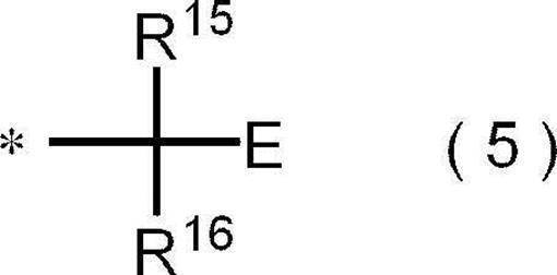
式(5)中、R15及びR16はそれぞれ独立に、水素原子、アルキル基又はアリール基を表し、Eはオニウム基を表し、*は式1-1又は式1-A中のLで表される酸素原子との結合部位を表す。
R15又はR16で表されるアルキル基は、R2~R9及びR0におけるアルキル基と同様であり、好ましい態様もR2~R9及びR0におけるアルキル基の好ましい態様と同様である。
R15又はR16で表されるアリール基は、R0におけるアリール基と同様であり、好ましい態様も、R0におけるアリール基の好ましい態様と同様である。
Eで表されるオニウム基は、R23におけるオニウム基と同様であり、好ましい態様もR23におけるオニウム基の好ましい態様と同様である。
R15又はR16で表されるアリール基は、R0におけるアリール基と同様であり、好ましい態様も、R0におけるアリール基の好ましい態様と同様である。
Eで表されるオニウム基は、R23におけるオニウム基と同様であり、好ましい態様もR23におけるオニウム基の好ましい態様と同様である。
式(5)において、Eで表されるオニウム基は、下記式(6)で表されるピリジニウム基が好ましい。

式(6)中、R17はハロゲン原子、アルキル基、アリール基、ヒドロキシ基又はアルコキシ基を表し、R17が複数存在する場合、複数のR17は同じでも異なってもよく、あるいは複数のR17が連結して環を形成してもよい。n2は0~4の整数を表す。R18はアルキル基又はアリール基を表す。Zbは電荷を中和するための対イオンを表す。
R17又はR18で表されるアルキル基又はアリール基は、R2~R9及びR0におけるアルキル基又はR0におけるアリール基と同様であり、好ましい態様もR2~R9及びR0におけるアルキル基又はR0におけるアリール基の好ましい態様と同様である。
R17で表されるアルコキシ基は、炭素数1~10のアルコキシ基が好ましく、メトキシ基、エトキシ基、n-プロポキシ基、イソプロポキシ基、n-ブトキシ基、イソブトキシ基、tert-ブトキシ基等が挙げられる。
n2は、好ましくは、0である。
Zbで表される電荷を中和するための対イオンは、式(1-7)におけるZ1と同様であり、好ましい態様も式(1-7)におけるZ1の好ましい態様と同様である。
R17で表されるアルコキシ基は、炭素数1~10のアルコキシ基が好ましく、メトキシ基、エトキシ基、n-プロポキシ基、イソプロポキシ基、n-ブトキシ基、イソブトキシ基、tert-ブトキシ基等が挙げられる。
n2は、好ましくは、0である。
Zbで表される電荷を中和するための対イオンは、式(1-7)におけるZ1と同様であり、好ましい態様も式(1-7)におけるZ1の好ましい態様と同様である。
以下に、式1-1又は式1-AにおいてLが酸素原子の場合、R1で表される基の具体例を挙げるが、本開示はこれらに限定されるものではない。下記構造式中、TsO-はトシレートアニオンを表し、●は式1-1又は式1-AのLで表される酸素原子との結合部位を表す。


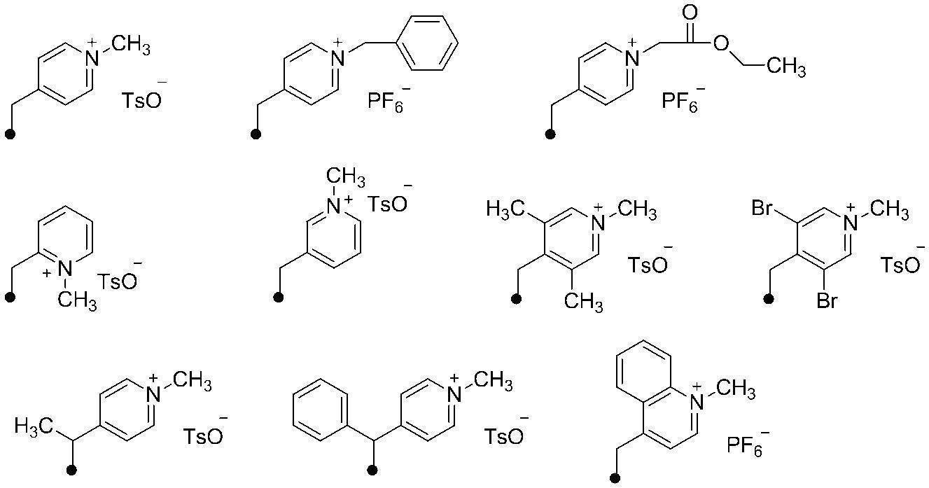


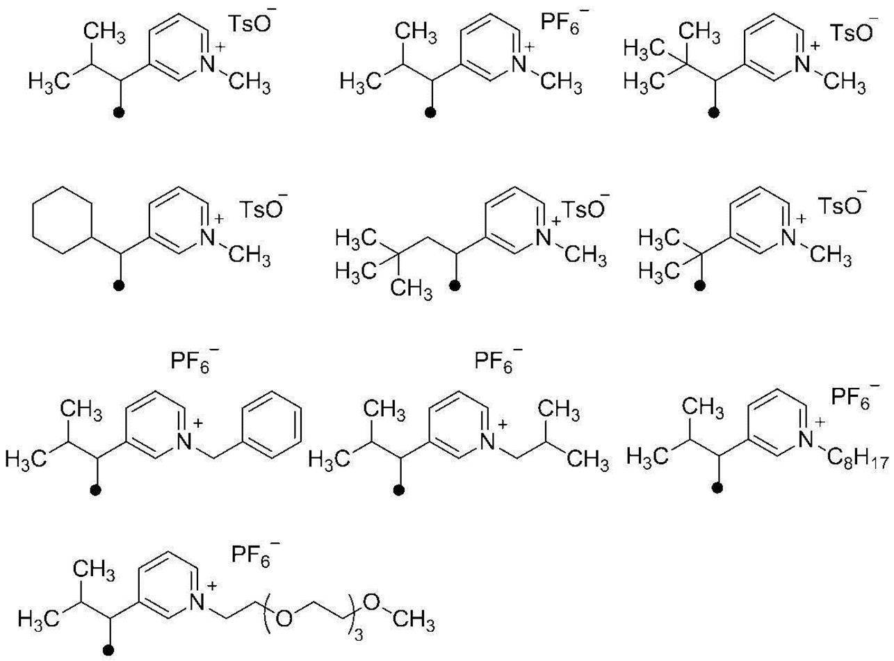

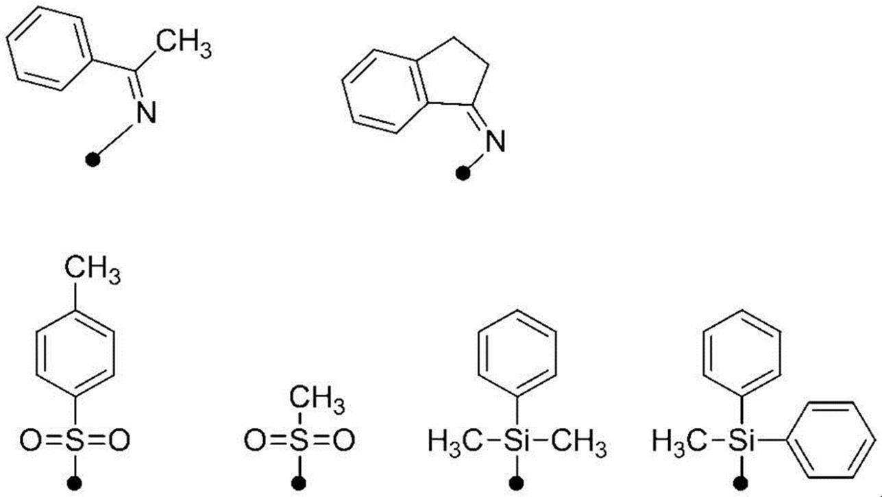

Lが酸素原子である場合、R1がアリール基又は直鎖のアルキル基であると、赤外線露光によるR1-O結合の開裂は起こらない。
式1-1又は式1-AにおいてLが硫黄原子である場合、R1は、下記式(2-1)で表される基が好ましい。
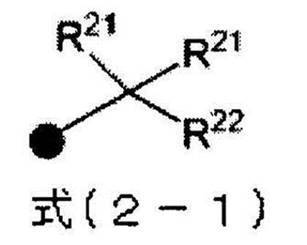
式(2-1)中、●は、式1-1又は式1-A中のLで表される硫黄原子との結合部位を表し、R21はそれぞれ独立に、水素原子、アルキル基又はアリール基を表し、R22はアリール基、アルケニル基、アルコキシ基又はオニウム基を表す。
式1-1又は式1-AにおいてLが-NR10-である場合、Nに結合するR1は、下記式(3-1)で表わされる基が好ましい。

式(3-1)中、●は、式1-1又は式1-A中のLに含まれる窒素原子との結合部位を表し、X1及びX2はそれぞれ独立に、酸素原子又は硫黄原子を表し、Yは、上記式(2-1)で表される基を表す。
上記式(2-1)において、R21及びR22で表されるアルキル基、アリール基、アルケニル基、アルコキシ基及びオニウム基については、上記式(1-1)~式(1-7)において記載したアルキル基、アリール基、アルケニル基、アルコキシ基及びオニウム基に関する記載を援用することができる。
式1-1又は式1-Aにおいて、Lが硫黄原子又は-NR10-を表し、R10が水素原子、アルキル基又はアリール基を表すことが、耐刷性の向上という観点から好ましい。
上記式1-1及び式1-AにおけるR1は、下記式2で表される基であることが好ましい。
また、上記式2で表される基は、赤外線露光により、式2中のRZ-O結合が開裂する基であることが好ましい。
また、上記式2で表される基は、赤外線露光により、式2中のRZ-O結合が開裂する基であることが好ましい。

式2中、RZは、アルキル基を表し、波線部分は、式1-1又は式1-A中のLで表される基との結合部位を表す。
RZで表されるアルキル基としては、上述のR2~R9及びR0におけるアルキル基の好ましい態様と同様である。
発色性、及び、得られる平版印刷版のUV耐刷性の観点から、上記アルキル基としては、第二級アルキル基又は第三級アルキル基であることが好ましく、第三級アルキル基であることが好ましい。
また、発色性、及び、得られる平版印刷版のUV耐刷性の観点から、上記アルキル基としては、炭素数1~8のアルキル基であることが好ましく、炭素数3~10の分岐状のアルキル基であることがより好ましく、炭素数3~6の分岐鎖状のアルキル基であることが更に好ましく、イソプロピル基又はtert-ブチル基が特に好ましく、t-ブチル基が最も好ましい。
RZで表されるアルキル基としては、上述のR2~R9及びR0におけるアルキル基の好ましい態様と同様である。
発色性、及び、得られる平版印刷版のUV耐刷性の観点から、上記アルキル基としては、第二級アルキル基又は第三級アルキル基であることが好ましく、第三級アルキル基であることが好ましい。
また、発色性、及び、得られる平版印刷版のUV耐刷性の観点から、上記アルキル基としては、炭素数1~8のアルキル基であることが好ましく、炭素数3~10の分岐状のアルキル基であることがより好ましく、炭素数3~6の分岐鎖状のアルキル基であることが更に好ましく、イソプロピル基又はtert-ブチル基が特に好ましく、t-ブチル基が最も好ましい。
以下に、上記式2で表される基の具体例を挙げるが、本開示はこれらに限定されるものではない。下記構造式中、●は式1-1又は式1-AのLとの結合部位を表す。

以下に、赤外線露光により分解する赤外線吸収剤の具体例を挙げるが、本開示はこれらに限定されるものではない。

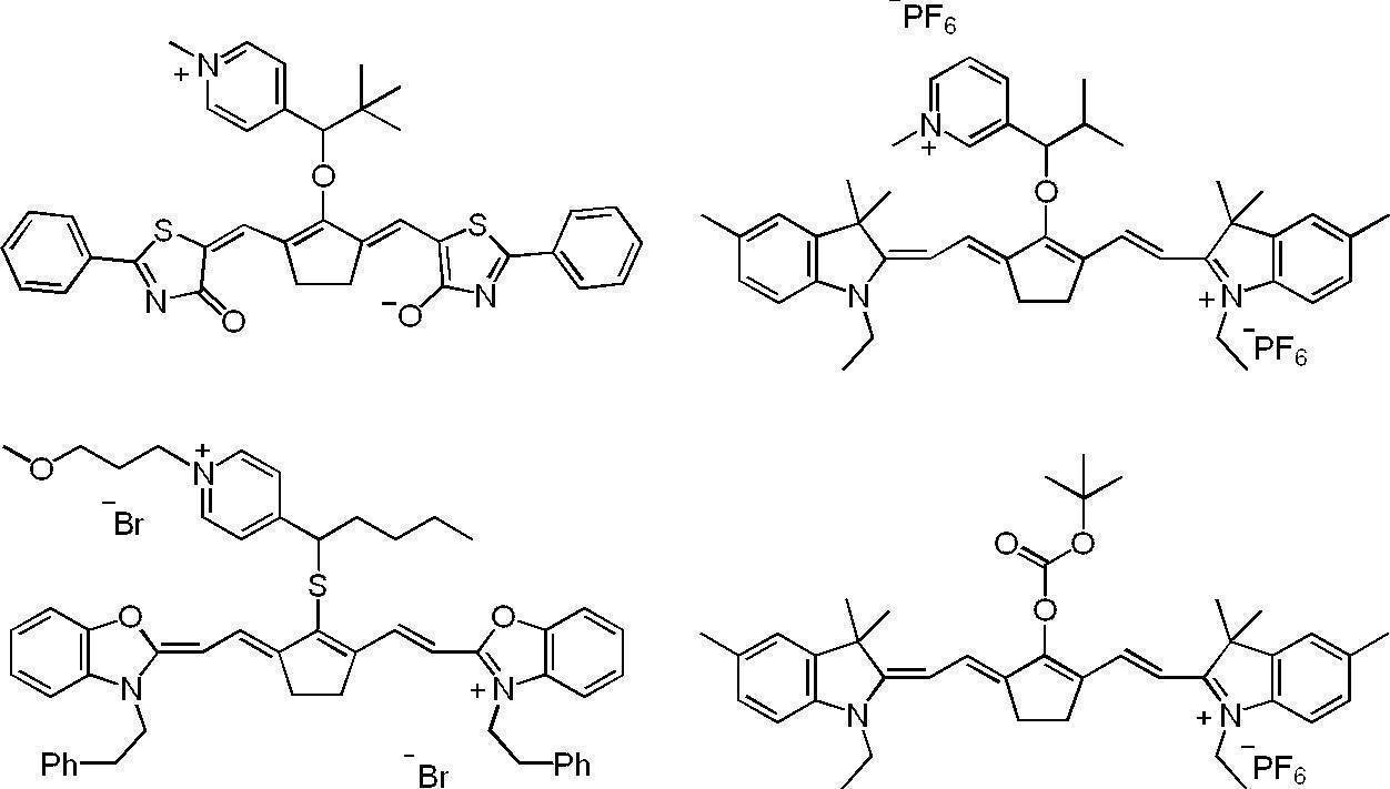

また、赤外線露光により分解する赤外線吸収剤としては、特表2008-544322号公報、又は、国際公開第2016/027886号に記載のものを好適に用いることができる。
赤外線吸収剤は、1種のみ用いてもよいし、2種以上を併用してもよい。また、赤外線吸収剤として顔料と染料とを併用してもよい。
上記画像記録層中の赤外線吸収剤の含有量は、画像記録層の全質量に対し、0.1質量%~10.0質量%が好ましく、0.5質量%~5.0質量%がより好ましい。
上記画像記録層中の赤外線吸収剤の含有量は、画像記録層の全質量に対し、0.1質量%~10.0質量%が好ましく、0.5質量%~5.0質量%がより好ましい。
〔電子供与型重合開始剤と、電子受容型重合開始剤と、赤外線吸収剤との関係〕
本開示における画像記録層は、上記電子供与型重合開始剤と、上記電子受容型重合開始剤と、上記赤外線吸収剤と、を含み、上記電子供与型重合開始剤のHOMOが-6.0eV以上であり、かつ、上記電子受容型重合開始剤のLUMOが-3.0eV以下であることが好ましい。
上記電子供与型重合開始剤のHOMO、及び、上記電子受容型重合開始剤のLUMOのより好ましい態様は、それぞれ上述の通りである。
本開示における画像記録層において、上記電子供与型重合開始剤と、上記赤外線吸収剤と、上記電子受容型重合開始剤とは、例えば、下記化学式に記載のようにエネルギーの受け渡しを行っていると推測される。
そのため、上記電子供与型重合開始剤のHOMOが-6.0eV以上であり、かつ、上記電子受容型重合開始剤のLUMOが-3.0eV以下であれば、ラジカルの発生効率が向上するため、耐薬品性及びUV耐刷性により優れやすいと考えられる。
本開示における画像記録層は、上記電子供与型重合開始剤と、上記電子受容型重合開始剤と、上記赤外線吸収剤と、を含み、上記電子供与型重合開始剤のHOMOが-6.0eV以上であり、かつ、上記電子受容型重合開始剤のLUMOが-3.0eV以下であることが好ましい。
上記電子供与型重合開始剤のHOMO、及び、上記電子受容型重合開始剤のLUMOのより好ましい態様は、それぞれ上述の通りである。
本開示における画像記録層において、上記電子供与型重合開始剤と、上記赤外線吸収剤と、上記電子受容型重合開始剤とは、例えば、下記化学式に記載のようにエネルギーの受け渡しを行っていると推測される。
そのため、上記電子供与型重合開始剤のHOMOが-6.0eV以上であり、かつ、上記電子受容型重合開始剤のLUMOが-3.0eV以下であれば、ラジカルの発生効率が向上するため、耐薬品性及びUV耐刷性により優れやすいと考えられる。
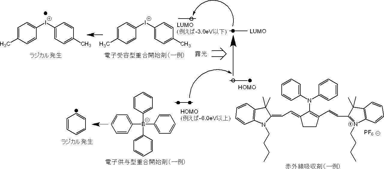
UV耐刷性及び耐薬品性の観点から、上記電子供与型重合開始剤のHOMOと、上記赤外線吸収剤のHOMOとの差は、1.00eV以下であることが好ましく、0.700eV以下であることがより好ましい。また、同様の観点から、上記電子供与型重合開始剤のHOMOと、上記赤外線吸収剤のHOMOとの差は、-0.200eV以上であることが好ましく、-0.100eV以上であることがより好ましい。
また、同様の観点から、上記電子供与型重合開始剤のHOMOと、上記赤外線吸収剤のHOMOとの差は、1.00eV~-0.200eVであることが好ましく、0.700eV~-0.100eVであることがより好ましい。なお、マイナスの値は、上記電子供与型重合開始剤のHOMOが、上記赤外線吸収剤のHOMOよりも高くなることを意味する。
また、UV耐刷性及び耐薬品性の観点から、上記赤外線吸収剤のLUMOと、上記電子受容型重合開始剤のLUMOとの差は、1.00eV以下であることが好ましく、0.700eV以下であることがより好ましい。また、同様の観点から、上記赤外線吸収剤のLUMOと、上記電子受容型重合開始剤のLUMOとの差は、-0.200eV以上であることが好ましく、-0.100eV以上であることがより好ましい。
また、同様の観点から、上記赤外線吸収剤のLUMOと、上記電子受容型重合開始剤のLUMOとの差は、1.00eV~-0.200eVであることが好ましく、0.700eV~-0.100eVであることがより好ましい。なお、マイナスの値は、上記赤外線吸収剤のLUMOが、上記電子受容型重合開始剤のLUMOよりも高くなることを意味する。
また、同様の観点から、上記電子供与型重合開始剤のHOMOと、上記赤外線吸収剤のHOMOとの差は、1.00eV~-0.200eVであることが好ましく、0.700eV~-0.100eVであることがより好ましい。なお、マイナスの値は、上記電子供与型重合開始剤のHOMOが、上記赤外線吸収剤のHOMOよりも高くなることを意味する。
また、UV耐刷性及び耐薬品性の観点から、上記赤外線吸収剤のLUMOと、上記電子受容型重合開始剤のLUMOとの差は、1.00eV以下であることが好ましく、0.700eV以下であることがより好ましい。また、同様の観点から、上記赤外線吸収剤のLUMOと、上記電子受容型重合開始剤のLUMOとの差は、-0.200eV以上であることが好ましく、-0.100eV以上であることがより好ましい。
また、同様の観点から、上記赤外線吸収剤のLUMOと、上記電子受容型重合開始剤のLUMOとの差は、1.00eV~-0.200eVであることが好ましく、0.700eV~-0.100eVであることがより好ましい。なお、マイナスの値は、上記赤外線吸収剤のLUMOが、上記電子受容型重合開始剤のLUMOよりも高くなることを意味する。
〔ポリマー粒子〕
上記画像記録層は、熱可塑性樹脂粒子以外のポリマー粒子を含んでいてもよい。
画像記録層が、ポリマー粒子を含む場合、上記画像記録層は、UV耐刷性及び機上現像性の観点から、親水性基を有するポリマー粒子を含むことが好ましい。
上記親水性基としては、親水性を有する構造であれば、特に制限はないが、カルボキシ基等の酸基、ヒドロキシ基、アミノ基、シアノ基、ポリアルキレンオキシド構造等が挙げられる。
上記親水性基としては、UV耐刷性及び機上現像性の観点から、ポリアルキレンオキシド構造を有する基、ポリエステル構造を有する基、又は、スルホン酸基であることが好ましく、ポリアルキレンオキシド構造を有する基、又は、スルホン酸基であることがより好ましく、ポリアルキレンオキシド構造を有する基であることが更に好ましい。
上記画像記録層は、熱可塑性樹脂粒子以外のポリマー粒子を含んでいてもよい。
画像記録層が、ポリマー粒子を含む場合、上記画像記録層は、UV耐刷性及び機上現像性の観点から、親水性基を有するポリマー粒子を含むことが好ましい。
上記親水性基としては、親水性を有する構造であれば、特に制限はないが、カルボキシ基等の酸基、ヒドロキシ基、アミノ基、シアノ基、ポリアルキレンオキシド構造等が挙げられる。
上記親水性基としては、UV耐刷性及び機上現像性の観点から、ポリアルキレンオキシド構造を有する基、ポリエステル構造を有する基、又は、スルホン酸基であることが好ましく、ポリアルキレンオキシド構造を有する基、又は、スルホン酸基であることがより好ましく、ポリアルキレンオキシド構造を有する基であることが更に好ましい。
上記ポリアルキレンオキシド構造としては、機上現像性の観点から、ポリエチレンオキシド構造、ポリプロピレンオキシド構造、又は、ポリ(エチレンオキシド/プロピレンオキシド)構造であることが好ましい。
また、機上現像性の観点からは、上記親水性基の中でもポリアルキレンオキシド構造として、ポリプロピレンオキシド構造を有することが好ましく、ポリエチレンオキシド構造及びポリプロピレンオキシド構造を有することがより好ましい。
上記ポリアルキレンオキシド構造におけるアルキレンオキシド構造の数は、機上現像性の観点から、2以上であることが好ましく、5以上であることがより好ましく、5~200であることが更に好ましく、8~150であることが特に好ましい。
また、機上現像性の観点からは、上記親水性基の中でもポリアルキレンオキシド構造として、ポリプロピレンオキシド構造を有することが好ましく、ポリエチレンオキシド構造及びポリプロピレンオキシド構造を有することがより好ましい。
上記ポリアルキレンオキシド構造におけるアルキレンオキシド構造の数は、機上現像性の観点から、2以上であることが好ましく、5以上であることがより好ましく、5~200であることが更に好ましく、8~150であることが特に好ましい。
ポリマー粒子は、熱反応性ポリマー粒子、重合性基を有するポリマー粒子、疎水性化合物を内包しているマイクロカプセル、及び、ミクロゲル(架橋ポリマー粒子)よりなる群から選ばれることが好ましい。中でも、重合性基を有するポリマー粒子又はミクロゲルが好ましい。特に好ましい実施形態では、ポリマー粒子は少なくとも1つのエチレン性不飽和重合性基を含む。このようなポリマー粒子の存在により、露光部のUV耐刷性及び未露光部の機上現像性を高める効果が得られる。
熱反応性ポリマー粒子としては、熱反応性基を有するポリマー粒子が挙げられる。熱反応性ポリマー粒子は熱反応による架橋及びその際の官能基変化により疎水化領域を形成する。
熱反応性基を有するポリマー粒子における熱反応性基としては、化学結合が形成されるならば、どのような反応を行う官能基でもよいが、重合性基であることが好ましく、その例として、ラジカル重合反応を行うエチレン性不飽和基(例えば、アクリロイル基、メタクリロイル基、ビニル基、アリル基など)、カチオン重合性基(例えば、ビニル基、ビニルオキシ基、エポキシ基、オキセタニル基など)、付加反応を行うイソシアナート基又はそのブロック体、エポキシ基、ビニルオキシ基及びこれらの反応相手である活性水素原子を有する官能基(例えば、アミノ基、ヒドロキシ基、カルボキシ基など)、縮合反応を行うカルボキシ基及び反応相手であるヒドロキシ基又はアミノ基、開環付加反応を行う酸無水物及び反応相手であるアミノ基又はヒドロキシ基などが好ましく挙げられる。
マイクロカプセルとしては、例えば、特開2001-277740号公報、特開2001-277742号公報に記載のごとく、画像記録層の構成成分の少なくとも一部をマイクロカプセルに内包させたものである。画像記録層の構成成分は、マイクロカプセル外にも含有させることもできる。マイクロカプセルを含有する画像記録層は、疎水性の構成成分をマイクロカプセルに内包し、親水性の構成成分をマイクロカプセル外に含有する構成が好ましい態様である。
ミクロゲル(架橋ポリマー粒子)は、その表面又は内部の少なくとも一方に、画像記録層の構成成分の一部を含有することができる。特に、ラジカル重合性基をその表面に有する反応性ミクロゲルは、画像形成感度やUV耐刷性の観点から好ましい。
画像記録層の構成成分をマイクロカプセル化又はミクロゲル化するには、公知の方法が適用できる。
また、ポリマー粒子としては、UV耐刷性、耐汚れ性及び保存安定性の観点から、分子中に2個以上のヒドロキシ基を有する多価フェノール化合物とイソホロンジイソシアネートとの付加物である多価イソシアネート化合物、及び、活性水素を有する化合物の反応により得られるものが好ましい。
上記多価フェノール化合物としては、フェノール性ヒドロキシ基を有するベンゼン環を複数有している化合物が好ましい。
上記活性水素を有する化合物としては、ポリオール化合物、又は、ポリアミン化合物が好ましく、ポリオール化合物がより好ましく、プロピレングリコール、グリセリン及びトリメチロールプロパンよりなる群から選ばれた少なくとも1種の化合物が更に好ましい。
分子中に2個以上のヒドロキシ基を有する多価フェノール化合物とイソホロンジイソシアネートとの付加物である多価イソシアネート化合物、及び、活性水素を有する化合物の反応により得られる樹脂の粒子としては、特開2012-206495号公報の段落0032~0095に記載のポリマー粒子が好ましく挙げられる。
上記多価フェノール化合物としては、フェノール性ヒドロキシ基を有するベンゼン環を複数有している化合物が好ましい。
上記活性水素を有する化合物としては、ポリオール化合物、又は、ポリアミン化合物が好ましく、ポリオール化合物がより好ましく、プロピレングリコール、グリセリン及びトリメチロールプロパンよりなる群から選ばれた少なくとも1種の化合物が更に好ましい。
分子中に2個以上のヒドロキシ基を有する多価フェノール化合物とイソホロンジイソシアネートとの付加物である多価イソシアネート化合物、及び、活性水素を有する化合物の反応により得られる樹脂の粒子としては、特開2012-206495号公報の段落0032~0095に記載のポリマー粒子が好ましく挙げられる。
更に、ポリマー粒子としては、UV耐刷性及び耐溶剤性の観点から、疎水性主鎖を有し、i)上記疎水性主鎖に直接的に結合されたペンダントシアノ基を有する構成ユニット、及び、ii)親水性ポリアルキレンオキシドセグメントを含むペンダント基を有する構成ユニットの両方を含むことが好ましい。
上記疎水性主鎖としては、アクリル樹脂鎖が好ましく挙げられる。
上記ペンダントシアノ基の例としては、-[CH2CH(C≡N)-]又は-[CH2C(CH3)(C≡N)-]が好ましく挙げられる。
また、上記ペンダントシアノ基を有する構成ユニットは、エチレン系不飽和型モノマー、例えば、アクリロニトリル又はメタクリロニトリルから、又は、これらの組み合わせから容易に誘導することができる。
また、上記親水性ポリアルキレンオキシドセグメントにおけるアルキレンオキシドとしては、エチレンオキシド又はプロピレンオキシドが好ましく、エチレンオキシドがより好ましい。
上記親水性ポリアルキレンオキシドセグメントにおけるアルキレンオキシド構造の繰り返し数は、10~100であることが好ましく、25~75であることがより好ましく、40~50であることが更に好ましい。
疎水性主鎖を有し、i)上記疎水性主鎖に直接的に結合されたペンダントシアノ基を有する構成ユニット、及び、ii)親水性ポリアルキレンオキシドセグメントを含むペンダント基を有する構成ユニットの両方を含む樹脂の粒子としては、特表2008-503365号公報の段落0039~0068に記載のものが好ましく挙げられる。
上記疎水性主鎖としては、アクリル樹脂鎖が好ましく挙げられる。
上記ペンダントシアノ基の例としては、-[CH2CH(C≡N)-]又は-[CH2C(CH3)(C≡N)-]が好ましく挙げられる。
また、上記ペンダントシアノ基を有する構成ユニットは、エチレン系不飽和型モノマー、例えば、アクリロニトリル又はメタクリロニトリルから、又は、これらの組み合わせから容易に誘導することができる。
また、上記親水性ポリアルキレンオキシドセグメントにおけるアルキレンオキシドとしては、エチレンオキシド又はプロピレンオキシドが好ましく、エチレンオキシドがより好ましい。
上記親水性ポリアルキレンオキシドセグメントにおけるアルキレンオキシド構造の繰り返し数は、10~100であることが好ましく、25~75であることがより好ましく、40~50であることが更に好ましい。
疎水性主鎖を有し、i)上記疎水性主鎖に直接的に結合されたペンダントシアノ基を有する構成ユニット、及び、ii)親水性ポリアルキレンオキシドセグメントを含むペンダント基を有する構成ユニットの両方を含む樹脂の粒子としては、特表2008-503365号公報の段落0039~0068に記載のものが好ましく挙げられる。
ポリマー粒子の平均粒径は、0.01μm~3.0μmが好ましく、0.03μm~2.0μmがより好ましく、0.10μm~1.0μmが更に好ましい。この範囲で良好な解像度と経時安定性が得られる。
本開示における上記各粒子の平均一次粒径は、光散乱法により測定するか、又は、粒子の電子顕微鏡写真を撮影し、写真上で粒子の粒径を総計で5,000個測定し、平均値を算出するものとする。なお、非球形粒子については写真上の粒子面積と同一の粒子面積を持つ球形粒子の粒径値を粒径とする。
また、本開示における平均粒径は、特に断りのない限り、体積平均粒径であるものとする。
ポリマー粒子の含有量は、画像記録層の全質量に対し、5質量%~90質量%が好ましい。
本開示における上記各粒子の平均一次粒径は、光散乱法により測定するか、又は、粒子の電子顕微鏡写真を撮影し、写真上で粒子の粒径を総計で5,000個測定し、平均値を算出するものとする。なお、非球形粒子については写真上の粒子面積と同一の粒子面積を持つ球形粒子の粒径値を粒径とする。
また、本開示における平均粒径は、特に断りのない限り、体積平均粒径であるものとする。
ポリマー粒子の含有量は、画像記録層の全質量に対し、5質量%~90質量%が好ましい。
〔酸発色剤〕
本開示において用いられる画像記録層は、酸発色剤を更に含むことが好ましい。
本開示で用いられる「酸発色剤」とは、電子受容性化合物(例えば酸等のプロトン)を受容した状態で加熱することにより、発色する性質を有する化合物を意味する。酸発色剤としては、特に、ラクトン、ラクタム、サルトン、スピロピラン、エステル、アミド等の部分骨格を有し、電子受容性化合物と接触した時に、速やかにこれらの部分骨格が開環若しくは開裂する無色の化合物が好ましい。
本開示において用いられる画像記録層は、酸発色剤を更に含むことが好ましい。
本開示で用いられる「酸発色剤」とは、電子受容性化合物(例えば酸等のプロトン)を受容した状態で加熱することにより、発色する性質を有する化合物を意味する。酸発色剤としては、特に、ラクトン、ラクタム、サルトン、スピロピラン、エステル、アミド等の部分骨格を有し、電子受容性化合物と接触した時に、速やかにこれらの部分骨格が開環若しくは開裂する無色の化合物が好ましい。
このような酸発色剤の例としては、3,3-ビス(4-ジメチルアミノフェニル)-6-ジメチルアミノフタリド(”クリスタルバイオレットラクトン”と称される)、3,3-ビス(4-ジメチルアミノフェニル)フタリド、3-(4-ジメチルアミノフェニル)-3-(4-ジエチルアミノ-2-メチルフェニル)-6-ジメチルアミノフタリド、3-(4-ジメチルアミノフェニル)-3-(1,2-ジメチルインドール-3-イル)フタリド、3-(4-ジメチルアミノフェニル)-3-(2-メチルインドール-3-イル)フタリド、3,3-ビス(1,2-ジメチルインドール-3-イル)-5-ジメチルアミノフタリド、3,3-ビス(1,2-ジメチルインドール-3-イル)-6-ジメチルアミノフタリド、3,3-ビス(9-エチルカルバゾール-3-イル)-6-ジメチルアミノフタリド、3,3-ビス(2-フェニルインドール-3-イル)-6-ジメチルアミノフタリド、3-(4-ジメチルアミノフェニル)-3-(1-メチルピロール-3-イル)-6-ジメチルアミノフタリド、
3,3-ビス〔1,1-ビス(4-ジメチルアミノフェニル)エチレン-2-イル〕-4,5,6,7-テトラクロロフタリド、3,3-ビス〔1,1-ビス(4-ピロリジノフェニル)エチレン-2-イル〕-4,5,6,7-テトラブロモフタリド、3,3-ビス〔1-(4-ジメチルアミノフェニル)-1-(4-メトキシフェニル)エチレン-2-イル〕-4,5,6,7-テトラクロロフタリド、3,3-ビス〔1-(4-ピロリジノフェニル)-1-(4-メトキシフェニル)エチレン-2-イル〕-4,5,6,7-テトラクロロフタリド、3-〔1,1-ジ(1-エチル-2-メチルインドール-3-イル)エチレン-2-イル〕-3-(4-ジエチルアミノフェニル)フタリド、3-〔1,1-ジ(1-エチル-2-メチルインドール-3-イル)エチレン-2-イル〕-3-(4-N-エチル-N-フェニルアミノフェニル)フタリド、3-(2-エトキシ-4-ジエチルアミノフェニル)-3-(1-n-オクチル-2-メチルインドール-3-イル)-フタリド、3,3-ビス(1-n-オクチル-2-メチルインドール-3-イル)-フタリド、3-(2-メチル-4-ジエチルアミノフェニル)-3-(1-n-オクチル-2-メチルインドール-3-イル)-フタリド等のフタリド類、
4,4-ビス-ジメチルアミノベンズヒドリンベンジルエーテル、N-ハロフェニル-ロイコオーラミン、N-2,4,5-トリクロロフェニルロイコオーラミン、ローダミン-B-アニリノラクタム、ローダミン-(4-ニトロアニリノ)ラクタム、ローダミン-B-(4-クロロアニリノ)ラクタム、3,7-ビス(ジエチルアミノ)-10-ベンゾイルフェノオキサジン、ベンゾイルロイコメチレンブルー、4ーニトロベンゾイルメチレンブルー、
3,6-ジメトキシフルオラン、3-ジメチルアミノ-7-メトキシフルオラン、3-ジエチルアミノ-6-メトキシフルオラン、3-ジエチルアミノ-7-メトキシフルオラン、3-ジエチルアミノ-7-クロロフルオラン、3-ジエチルアミノ-6-メチル-7-クロロフルオラン、3-ジエチルアミノ-6,7-ジメチルフルオラン、3-N-シクロヘキシル-N-n-ブチルアミノ-7-メチルフルオラン、3-ジエチルアミノ-7-ジベンジルアミノフルオラン、3-ジエチルアミノ-7-オクチルアミノフルオラン、3-ジエチルアミノ-7-ジ-n-ヘキシルアミノフルオラン、3-ジエチルアミノ-7-アニリノフルオラン、3-ジエチルアミノ-7-(2’-フルオロフェニルアミノ)フルオラン、3-ジエチルアミノ-7-(2’-クロロフェニルアミノ)フルオラン、3-ジエチルアミノ-7-(3’-クロロフェニルアミノ)フルオラン、3-ジエチルアミノ-7-(2’,3’-ジクロロフェニルアミノ)フルオラン、3-ジエチルアミノ-7-(3’-トリフルオロメチルフェニルアミノ)フルオラン、3-ジ-n-ブチルアミノ-7-(2’-フルオロフェニルアミノ)フルオラン、3-ジ-n-ブチルアミノ-7-(2’-クロロフェニルアミノ)フルオラン、3-N-イソペンチル-N-エチルアミノ-7-(2’-クロロフェニルアミノ)フルオラン、
3-N-n-ヘキシル-N-エチルアミノ-7-(2’-クロロフェニルアミノ)フルオラン、3-ジエチルアミノ-6-クロロ-7-アニリノフルオラン、3-ジ-n-ブチルアミノ-6-クロロ-7-アニリノフルオラン、3-ジエチルアミノ-6-メトキシ-7-アニリノフルオラン、3-ジ-n-ブチルアミノ-6-エトキシ-7-アニリノフルオラン、3-ピロリジノ-6-メチル-7-アニリノフルオラン、3-ピペリジノ-6-メチル-7-アニリノフルオラン、3-モルホリノ-6-メチル-7-アニリノフルオラン、3-ジメチルアミノ-6-メチル-7-アニリノフルオラン、3-ジエチルアミノ-6-メチル-7-アニリノフルオラン、3-ジ-n-ブチルアミノ-6-メチル-7-アニリノフルオラン、3-ジ-n-ペンチルアミノ-6-メチル-7-アニリノフルオラン、3-N-エチル-N-メチルアミノ-6-メチル-7-アニリノフルオラン、3-N-n-プロピル-N-メチルアミノ-6-メチル-7-アニリノフルオラン、3-N-n-プロピル-N-エチルアミノ-6-メチル-7-アニリノフルオラン、3-N-n-ブチル-N-メチルアミノ-6-メチル-7-アニリノフルオラン、3-N-n-ブチル-N-エチルアミノ-6-メチル-7-アニリノフルオラン、3-N-イソブチル-N-メチルアミノ-6-メチル-7-アニリノフルオラン、3-N-イソブチル-N-エチルアミノ-6-メチル-7-アニリノフルオラン、3-N-イソペンチル-N-エチルアミノ-6-メチル-7-アニリノフルオラン、3-N-n-ヘキシル-N-メチルアミノ-6-メチル-7-アニリノフルオラン、3-N-シクロヘキシル-N-エチルアミノ-6-メチル-7-アニリノフルオラン、3-N-シクロヘキシル-N-n-プロピルアミノ-6-メチル-7-アニリノフルオラン、3-N-シクロヘキシル-N-n-ブチルアミノ-6-メチル-7-アニリノフルオラン、3-N-シクロヘキシル-N-n-ヘキシルアミノ-6-メチル-7-アニリノフルオラン、3-N-シクロヘキシル-N-n-オクチルアミノ-6-メチル-7-アニリノフルオラン、
3-N-(2’-メトキシエチル)-N-メチルアミノ-6-メチル-7-アニリノフルオラン、3-N-(2’-メトキシエチル)-N-エチルアミノ-6-メチル-7-アニリノフルオラン、3-N-(2’-メトキシエチル)-N-イソブチルアミノ-6-メチル-7-アニリノフルオラン、3-N-(2’-エトキシエチル)-N-メチルアミノ-6-メチル-7-アニリノフルオラン、3-N-(2’-エトキシエチル)-N-エチルアミノ-6-メチル-7-アニリノフルオラン、3-N-(3’-メトキシプロピル)-N-メチルアミノ-6-メチル-7-アニリノフルオラン、3-N-(3’-メトキシプロピル)-N-エチルアミノ-6-メチル-7-アニリノフルオラン、3-N-(3’-エトキシプロピル)-N-メチルアミノ-6-メチル-7-アニリノフルオラン、3-N-(3’-エトキシプロピル)-N-エチルアミノ-6-メチル-7-アニリノフルオラン、3-N-(2’-テトラヒドロフルフリル)-N-エチルアミノ-6-メチル-7-アニリノフルオラン、3-N-(4’-メチルフェニル)-N-エチルアミノ-6-メチル-7-アニリノフルオラン、3-ジエチルアミノ-6-エチル-7-アニリノフルオラン、3-ジエチルアミノ-6-メチル-7-(3’-メチルフェニルアミノ)フルオラン、3-ジエチルアミノ-6-メチル-7-(2’,6’-ジメチルフェニルアミノ)フルオラン、3-ジ-n-ブチルアミノ-6-メチル-7-(2’,6’-ジメチルフェニルアミノ)フルオラン、3-ジ-n-ブチルアミノ-7-(2’,6’-ジメチルフェニルアミノ)フルオラン、2,2-ビス〔4’-(3-N-シクロヘキシル-N-メチルアミノ-6-メチルフルオラン)-7-イルアミノフェニル〕プロパン、3-〔4’-(4-フェニルアミノフェニル)アミノフェニル〕アミノ-6-メチル-7-クロロフルオラン、3-〔4’-(ジメチルアミノフェニル)〕アミノ-5,7-ジメチルフルオラン等のフルオラン類、
3-(2-メチル-4-ジエチルアミノフェニル)-3-(1-エチル-2-メチルインドール-3-イル)-4-アザフタリド、3-(2-n-プロポキシカルボニルアミノ-4-ジ-n-プロピルアミノフェニル)-3-(1-エチル-2-メチルインドール-3-イル)-4-アザフタリド、3-(2-メチルアミノ-4-ジ-n-プロピルアミノフェニル)-3-(1-エチル-2-メチルインドール-3-イル)-4-アザフタリド、3-(2-メチル-4-ジn-ヘキシルアミノフェニル)-3-(1-n-オクチル-2-メチルインドール-3-イル)-4,7-ジアザフタリド、3,3-ビス(2-エトキシ-4-ジエチルアミノフェニル)-4-アザフタリド、3,3-ビス(1-n-オクチル-2-メチルインドール-3-イル)-4-アザフタリド、3-(2-エトキシ-4-ジエチルアミノフェニル)-3-(1-エチル-2-メチルインドール-3-イル)-4-アザフタリド、3-(2-エトキシ-4-ジエチルアミノフェニル)-3-(1-オクチル-2-メチルインドール-3-イル)-4又は7-アザフタリド、3-(2-エトキシ-4-ジエチルアミノフェニル)-3-(1-エチル-2-メチルインドール-3-イル)-4又は7-アザフタリド、3-(2-ヘキシルオキシ-4-ジエチルアミノフェニル)-3-(1-エチル-2-メチルインドール-3-イル)-4又は7-アザフタリド、3-(2-エトキシ-4-ジエチルアミノフェニル)-3-(1-エチル-2-フェニルインドール-3-イル)-4又は7-アザフタリド、3-(2-ブトキシ-4-ジエチルアミノフェニル)-3-(1-エチル-2-フェニルインドール-3-イル)-4又は7-アザフタリド3-メチル-スピロ-ジナフトピラン、3-エチル-スピロ-ジナフトピラン、3-フェニル-スピロ-ジナフトピラン、3-ベンジル-スピロ-ジナフトピラン、3-メチル-ナフト-(3-メトキシベンゾ)スピロピラン、3-プロピル-スピロ-ジベンゾピラン-3,6-ビス(ジメチルアミノ)フルオレン-9-スピロ-3’-(6’-ジメチルアミノ)フタリド、3,6-ビス(ジエチルアミノ)フルオレン-9-スピロ-3’-(6’-ジメチルアミノ)フタリド等のフタリド類、
その他、2’-アニリノ-6’-(N-エチル-N-イソペンチル)アミノ-3’-メチルスピロ[イソベンゾフラン-1(3H),9’-(9H)キサンテン-3-オン、2’-アニリノ-6’-(N-エチル-N-(4-メチルフェニル))アミノ-3’-メチルスピロ[イソベンゾフラン-1(3H),9’-(9H)キサンテン]-3-オン、3’-N,N-ジベンジルアミノ-6’-N,N-ジエチルアミノスピロ[イソベンゾフラン-1(3H),9’-(9H)キサンテン]-3-オン、2’-(N-メチル-N-フェニル)アミノ-6’-(N-エチル-N-(4-メチルフェニル))アミノスピロ[イソベンゾフラン-1(3H),9’-(9H)キサンテン]-3-オンなどが挙げられる。
中でも、本開示に用いられる酸発色剤は、発色性の観点から、スピロピラン化合物、スピロオキサジン化合物、スピロラクトン化合物、及び、スピロラクタム化合物よりなる群から選ばれた少なくとも1種の化合物であることが好ましい。
発色後の色素の色相としては、可視性の観点から、緑、青又は黒であることが好ましい。
発色後の色素の色相としては、可視性の観点から、緑、青又は黒であることが好ましい。
酸発色剤としては上市されている製品を使用することも可能であり、ETAC、RED500、RED520、CVL、S-205、BLACK305、BLACK400、BLACK100、BLACK500、H-7001、GREEN300、NIRBLACK78、BLUE220、H-3035、BLUE203、ATP、H-1046、H-2114(以上、福井山田化学工業(株)製)、ORANGE-DCF、Vermilion-DCF、PINK-DCF、RED-DCF、BLMB、CVL、GREEN-DCF、TH-107(以上、保土ヶ谷化学(株)製)、ODB、ODB-2、ODB-4、ODB-250、ODB-BlackXV、Blue-63、Blue-502、GN-169、GN-2、Green-118、Red-40、Red-8(以上、山本化成(株)製)、クリスタルバイオレットラクトン(東京化成工業(株)製)等が挙げられる。これらの市販品の中でも、ETAC、S-205、BLACK305、BLACK400、BLACK100、BLACK500、H-7001、GREEN300、NIRBLACK78、H-3035、ATP、H-1046、H-2114、GREEN-DCF、Blue-63、GN-169、クリスタルバイオレットラクトンが、形成される膜の可視光吸収率が良好のため好ましい。
これらの酸発色剤は、1種単独で用いてもよいし、2種類以上の成分を組み合わせて使用することもできる。
酸発色剤の含有量は、画像記録層の全質量に対し、0.5質量%~10質量%であることが好ましく、1質量%~5質量%であることがより好ましい。
酸発色剤の含有量は、画像記録層の全質量に対し、0.5質量%~10質量%であることが好ましく、1質量%~5質量%であることがより好ましい。
〔熱可塑性樹脂粒子以外のバインダーポリマー〕
画像記録層は、熱可塑性樹脂粒子以外のバインダーポリマー(以下、「他のバインダーポリマー」ともいう。)を含んでもよい。
上記熱可塑性樹脂粒子、及び、上記ポリマー粒子は、上記他のバインダーポリマーに該当しない。すなわち、他のバインダーポリマーは、粒子形状ではない重合体である。
他のバインダーポリマーとしては、(メタ)アクリル樹脂、ポリビニルアセタール樹脂、又は、ポリウレタン樹脂が好ましい。
画像記録層は、熱可塑性樹脂粒子以外のバインダーポリマー(以下、「他のバインダーポリマー」ともいう。)を含んでもよい。
上記熱可塑性樹脂粒子、及び、上記ポリマー粒子は、上記他のバインダーポリマーに該当しない。すなわち、他のバインダーポリマーは、粒子形状ではない重合体である。
他のバインダーポリマーとしては、(メタ)アクリル樹脂、ポリビニルアセタール樹脂、又は、ポリウレタン樹脂が好ましい。
中でも、他のバインダーポリマーは平版印刷版原版の画像記録層に用いられる公知のバインダーポリマーを好適に使用することができる。一例として、機上現像型の平版印刷版原版に用いられるバインダーポリマー(以下、機上現像用バインダーポリマーともいう)について、詳細に記載する。
機上現像用バインダーポリマーとしては、アルキレンオキシド鎖を有するバインダーポリマーが好ましい。アルキレンオキシド鎖を有するバインダーポリマーは、ポリ(アルキレンオキシド)部位を主鎖に有していても側鎖に有していてもよい。また、ポリ(アルキレンオキシド)を側鎖に有するグラフトポリマーでも、ポリ(アルキレンオキシド)含有繰返し単位で構成されるブロックと(アルキレンオキシド)非含有繰返し単位で構成されるブロックとのブロックコポリマーでもよい。
ポリ(アルキレンオキシド)部位を主鎖に有する場合は、ポリウレタン樹脂が好ましい。ポリ(アルキレンオキシド)部位を側鎖に有する場合の主鎖のポリマーとしては、(メタ)アクリル樹脂、ポリビニルアセタール樹脂、ポリウレタン樹脂、ポリウレア樹脂、ポリイミド樹脂、ポリアミド樹脂、エポキシ樹脂、ポリスチレン樹脂、ノボラック型フェノール樹脂、ポリエステル樹脂、合成ゴム、天然ゴムが挙げられ、特に(メタ)アクリル樹脂が好ましい。
機上現像用バインダーポリマーとしては、アルキレンオキシド鎖を有するバインダーポリマーが好ましい。アルキレンオキシド鎖を有するバインダーポリマーは、ポリ(アルキレンオキシド)部位を主鎖に有していても側鎖に有していてもよい。また、ポリ(アルキレンオキシド)を側鎖に有するグラフトポリマーでも、ポリ(アルキレンオキシド)含有繰返し単位で構成されるブロックと(アルキレンオキシド)非含有繰返し単位で構成されるブロックとのブロックコポリマーでもよい。
ポリ(アルキレンオキシド)部位を主鎖に有する場合は、ポリウレタン樹脂が好ましい。ポリ(アルキレンオキシド)部位を側鎖に有する場合の主鎖のポリマーとしては、(メタ)アクリル樹脂、ポリビニルアセタール樹脂、ポリウレタン樹脂、ポリウレア樹脂、ポリイミド樹脂、ポリアミド樹脂、エポキシ樹脂、ポリスチレン樹脂、ノボラック型フェノール樹脂、ポリエステル樹脂、合成ゴム、天然ゴムが挙げられ、特に(メタ)アクリル樹脂が好ましい。
また、他のバインダーポリマーの他の好ましい例として、6官能以上10官能以下の多官能チオールを核として、この核に対しスルフィド結合により結合したポリマー鎖を有し、上記ポリマー鎖が重合性基を有する高分子化合物(以下、星型高分子化合物ともいう。)が挙げられる。星型高分子化合物としては、例えば、特開2012-148555号公報に記載の化合物を好ましく用いることができる。
星型高分子化合物は、特開2008-195018号公報に記載のような画像部の皮膜強度を向上するためのエチレン性不飽和結合等の重合性基を、主鎖又は側鎖、好ましくは側鎖に有しているものが挙げられる。重合性基によってポリマー分子間に架橋が形成され、硬化が促進する。
重合性基としては、(メタ)アクリル基、ビニル基、アリル基、ビニルフェニル基(スチリル基)などのエチレン性不飽和基やエポキシ基等が好ましく、(メタ)アクリル基、ビニル基、ビニルフェニル基(スチリル基)が重合反応性の観点でより好ましく、(メタ)アクリル基が特に好ましい。これらの基は高分子反応や共重合によってポリマーに導入することができる。例えば、カルボキシ基を側鎖に有するポリマーとグリシジルメタクリレートとの反応、あるいはエポキシ基を有するポリマーとメタクリル酸などのエチレン性不飽和基含有カルボン酸との反応を利用できる。これらの基は併用してもよい。
重合性基としては、(メタ)アクリル基、ビニル基、アリル基、ビニルフェニル基(スチリル基)などのエチレン性不飽和基やエポキシ基等が好ましく、(メタ)アクリル基、ビニル基、ビニルフェニル基(スチリル基)が重合反応性の観点でより好ましく、(メタ)アクリル基が特に好ましい。これらの基は高分子反応や共重合によってポリマーに導入することができる。例えば、カルボキシ基を側鎖に有するポリマーとグリシジルメタクリレートとの反応、あるいはエポキシ基を有するポリマーとメタクリル酸などのエチレン性不飽和基含有カルボン酸との反応を利用できる。これらの基は併用してもよい。
他のバインダーポリマーの分子量は、GPC法によるポリスチレン換算値として重量平均分子量(Mw)が、2,000以上であることが好ましく、5,000以上であることがより好ましく、10,000~300,000であることが更に好ましい。
必要に応じて、特開2008-195018号公報に記載のポリアクリル酸、ポリビニルアルコールなどの親水性ポリマーを併用することができる。また、親油的なポリマーと親水的なポリマーとを併用することもできる。
本開示において用いられる画像記録層においては、他のバインダーポリマーを1種単独で使用しても、2種以上を併用してもよい。
他のバインダーポリマーは、画像記録層中に任意な量で含有させることができるが、バインダーポリマーの含有量は、画像記録層の全質量に対して、1質量%~90質量%であることが好ましく、5質量%~80質量%であることがより好ましい。
また、本開示における画像記録層が他のバインダーポリマーを含む場合、上記熱可塑性樹脂粒子と他のバインダーポリマーとの合計質量に対する他のバインダーポリマーの含有量は、0質量%を超え99質量%以下であることが好ましく、20質量%~95質量%であることがより好ましく、40質量%~90質量%であることが更に好ましい。
他のバインダーポリマーは、画像記録層中に任意な量で含有させることができるが、バインダーポリマーの含有量は、画像記録層の全質量に対して、1質量%~90質量%であることが好ましく、5質量%~80質量%であることがより好ましい。
また、本開示における画像記録層が他のバインダーポリマーを含む場合、上記熱可塑性樹脂粒子と他のバインダーポリマーとの合計質量に対する他のバインダーポリマーの含有量は、0質量%を超え99質量%以下であることが好ましく、20質量%~95質量%であることがより好ましく、40質量%~90質量%であることが更に好ましい。
〔連鎖移動剤〕
本開示において用いられる画像記録層は、連鎖移動剤を含有してもよい。連鎖移動剤は、平版印刷版におけるUV耐刷性の向上に寄与する。
連鎖移動剤としては、チオール化合物が好ましく、沸点(揮発し難さ)の観点で炭素数7以上のチオール化合物がより好ましく、芳香環上にメルカプト基を有する化合物(芳香族チオール化合物)が更に好ましい。上記チオール化合物は単官能チオール化合物であることが好ましい。
本開示において用いられる画像記録層は、連鎖移動剤を含有してもよい。連鎖移動剤は、平版印刷版におけるUV耐刷性の向上に寄与する。
連鎖移動剤としては、チオール化合物が好ましく、沸点(揮発し難さ)の観点で炭素数7以上のチオール化合物がより好ましく、芳香環上にメルカプト基を有する化合物(芳香族チオール化合物)が更に好ましい。上記チオール化合物は単官能チオール化合物であることが好ましい。
連鎖移動剤として具体的には、下記の化合物が挙げられる。
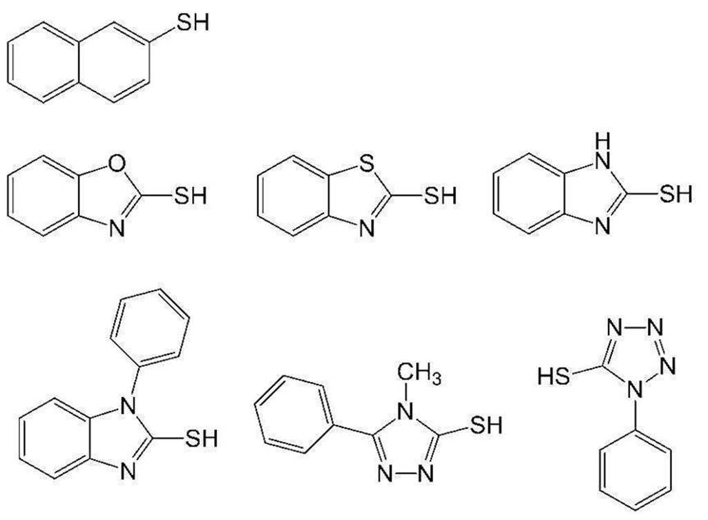
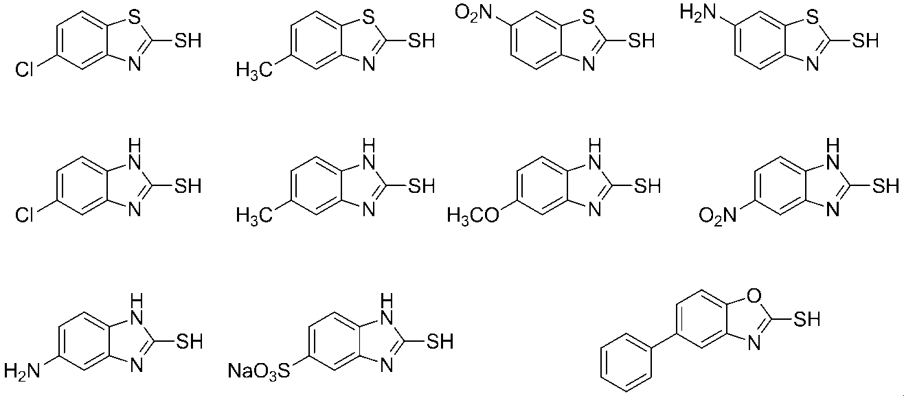


連鎖移動剤は、1種のみを添加しても、2種以上を併用してもよい。
連鎖移動剤の含有量は、画像記録層の全質量に対し、0.01質量%~50質量%が好ましく、0.05質量%~40質量%がより好ましく、0.1質量%~30質量%が更に好ましい。
連鎖移動剤の含有量は、画像記録層の全質量に対し、0.01質量%~50質量%が好ましく、0.05質量%~40質量%がより好ましく、0.1質量%~30質量%が更に好ましい。
〔感脂化剤〕
画像記録層は、インキ着肉性を向上させるために、感脂化剤を更に含有することが好ましい。
感脂化剤は、SP値が18.0未満であることが好ましく、14~18未満であることがより好ましく、15~17であることが更に好ましく、16~16.9であることが特に好ましい。
また、感脂化剤は、分子量(分子量分布があるときは、重量平均分子量)が2,000以上の化合物であってもよく、分子量が2,000未満の化合物であってもよい。
画像記録層は、インキ着肉性を向上させるために、感脂化剤を更に含有することが好ましい。
感脂化剤は、SP値が18.0未満であることが好ましく、14~18未満であることがより好ましく、15~17であることが更に好ましく、16~16.9であることが特に好ましい。
また、感脂化剤は、分子量(分子量分布があるときは、重量平均分子量)が2,000以上の化合物であってもよく、分子量が2,000未満の化合物であってもよい。
本開示におけるSP値(溶解度パラメーター、単位:(MPa)1/2))は、ハンセン(Hansen)溶解度パラメーターを用いるものとする。
ハンセン(Hansen)溶解度パラメーターは、ヒルデブランド(Hildebrand)によって導入された溶解度パラメーターを、分散項δd、極性項δp、水素結合項δhの3成分に分割し、3次元空間に表したものであるが、本開示においてはSP値をδ(単位:(MPa)1/2)で表し、下記式を用いて算出される値を用いる。
δ(MPa)1/2=(δd2+δp2+δh2)1/2
なお、この分散項δd、極性項δp、及び、水素結合項δhは、ハンセンやその研究後継者らにより多く求められており、Polymer Handbook (fourth edition)、VII-698~711に詳しく掲載されている。
また本開示において、ポリマーのSP値は、ポリマーの分子構造からPolymer Handbook fourth editionに記載のHoy法により計算する。
ハンセン(Hansen)溶解度パラメーターは、ヒルデブランド(Hildebrand)によって導入された溶解度パラメーターを、分散項δd、極性項δp、水素結合項δhの3成分に分割し、3次元空間に表したものであるが、本開示においてはSP値をδ(単位:(MPa)1/2)で表し、下記式を用いて算出される値を用いる。
δ(MPa)1/2=(δd2+δp2+δh2)1/2
なお、この分散項δd、極性項δp、及び、水素結合項δhは、ハンセンやその研究後継者らにより多く求められており、Polymer Handbook (fourth edition)、VII-698~711に詳しく掲載されている。
また本開示において、ポリマーのSP値は、ポリマーの分子構造からPolymer Handbook fourth editionに記載のHoy法により計算する。
上記感脂化剤としては、例えば、オニウム化合物、含窒素低分子化合物、アンモニウム基含有ポリマー等のアンモニウム化合物などが挙げられる。
特に、オーバーコート層に無機層状化合物を含有させる場合、これら化合物は、無機層状化合物の表面被覆剤として機能し、無機層状化合物による印刷途中の着肉性低下を抑制することができる。
特に、オーバーコート層に無機層状化合物を含有させる場合、これら化合物は、無機層状化合物の表面被覆剤として機能し、無機層状化合物による印刷途中の着肉性低下を抑制することができる。
また、感脂化剤は、着肉性の観点から、オニウム化合物であることが好ましい。
オニウム化合物としては、ホスホニウム化合物、アンモニウム化合物、スルホニウム化合物等が挙げられ、オニウム化合物としては、上記観点から、ホスホニウム化合物及びアンモニウム化合物からなる群より選択される少なくとも1つが好ましい。
また、後述する、現像促進剤又は電子受容型重合開始剤におけるオニウム化合物はSP値が18を超える化合物であり、感脂化剤には含まれない。
オニウム化合物としては、ホスホニウム化合物、アンモニウム化合物、スルホニウム化合物等が挙げられ、オニウム化合物としては、上記観点から、ホスホニウム化合物及びアンモニウム化合物からなる群より選択される少なくとも1つが好ましい。
また、後述する、現像促進剤又は電子受容型重合開始剤におけるオニウム化合物はSP値が18を超える化合物であり、感脂化剤には含まれない。
ホスホニウム化合物としては、特開2006-297907号公報及び特開2007-50660号公報に記載のホスホニウム化合物が挙げられる。具体例としては、1,4-ビス(トリフェニルホスホニオ)ブタン=ジ(ヘキサフルオロホスファート)、1,7-ビス(トリフェニルホスホニオ)ヘプタン=スルファート、1,9-ビス(トリフェニルホスホニオ)ノナン=ナフタレン-2,7-ジスルホナート等が挙げられる。
アンモニウム化合物としては、含窒素低分子化合物、アンモニウム基含有ポリマー等を好ましく挙げることができる。
含窒素低分子化合物としては、アミン塩類、第四級アンモニウム塩類が挙げられる。また、イミダゾリニウム塩類、ベンゾイミダゾリニウム塩類、ピリジニウム塩類、キノリニウム塩類も挙げられる。
中でも、第四級アンモニウム塩類及びピリジニウム塩類が好ましい。
具体例としては、テトラメチルアンモニウム=ヘキサフルオロホスファート、テトラブチルアンモニウム=ヘキサフルオロホスファート、ドデシルトリメチルアンモニウム=p-トルエンスルホナート、ベンジルトリエチルアンモニウム=ヘキサフルオロホスファート、ベンジルジメチルオクチルアンモニウム=ヘキサフルオロホスファート、ベンジルジメチルドデシルアンモニウム=ヘキサフルオロホスファート、特開2008-284858号公報の段落0021~0037に記載の化合物、特開2009-90645号公報の段落0030~0057に記載の化合物等が挙げられる。
中でも、第四級アンモニウム塩類及びピリジニウム塩類が好ましい。
具体例としては、テトラメチルアンモニウム=ヘキサフルオロホスファート、テトラブチルアンモニウム=ヘキサフルオロホスファート、ドデシルトリメチルアンモニウム=p-トルエンスルホナート、ベンジルトリエチルアンモニウム=ヘキサフルオロホスファート、ベンジルジメチルオクチルアンモニウム=ヘキサフルオロホスファート、ベンジルジメチルドデシルアンモニウム=ヘキサフルオロホスファート、特開2008-284858号公報の段落0021~0037に記載の化合物、特開2009-90645号公報の段落0030~0057に記載の化合物等が挙げられる。
アンモニウム基含有ポリマーとしては、その構造中にアンモニウム基を有すればよく、側鎖にアンモニウム基を有する(メタ)アクリレートを共重合成分として5mol%~80mol%含有するポリマーが好ましい。具体例としては、特開2009-208458号公報の段落0089~0105に記載のポリマーが挙げられる。
アンモニウム塩含有ポリマーは、特開2009-208458号公報に記載の測定方法に従って求められる還元比粘度(単位:ml/g)の値が、5~120の範囲のものが好ましく、10~110の範囲のものがより好ましく、15~100の範囲のものが特に好ましい。上記還元比粘度を重量平均分子量(Mw)に換算した場合、10,000~150,000が好ましく、17,000~140,000がより好ましく、20,000~130,000が特に好ましい。
以下に、アンモニウム基含有ポリマーの具体例を示す。
(1)2-(トリメチルアンモニオ)エチルメタクリレート=p-トルエンスルホナート/3,6-ジオキサヘプチルメタクリレート共重合体(モル比10/90、Mw4.5万)
(2)2-(トリメチルアンモニオ)エチルメタクリレート=ヘキサフルオロホスファート/3,6-ジオキサヘプチルメタクリレート共重合体(モル比20/80、Mw6.0万)
(3)2-(エチルジメチルアンモニオ)エチルメタクリレート=p-トルエンスルホナート/ヘキシルメタクリレート共重合体(モル比30/70、Mw4.5万)
(4)2-(トリメチルアンモニオ)エチルメタクリレート=ヘキサフルオロホスファート/2-エチルヘキシルメタクリレート共重合体(モル比20/80、Mw6.0万)
(5)2-(トリメチルアンモニオ)エチルメタクリレート=メチルスルファート/ヘキシルメタクリレート共重合体(モル比40/60、Mw7.0万)
(6)2-(ブチルジメチルアンモニオ)エチルメタクリレート=ヘキサフルオロホスファート/3,6-ジオキサヘプチルメタクリレート共重合体(モル比25/75、Mw6.5万)
(7)2-(ブチルジメチルアンモニオ)エチルアクリレート=ヘキサフルオロホスファート/3,6-ジオキサヘプチルメタクリレート共重合体(モル比20/80、Mw6.5万)
(8)2-(ブチルジメチルアンモニオ)エチルメタクリレート=13-エチル-5,8,11-トリオキサ-1-ヘプタデカンスルホナート/3,6-ジオキサヘプチルメタクリレート共重合体(モル比20/80、Mw7.5万)
(1)2-(トリメチルアンモニオ)エチルメタクリレート=p-トルエンスルホナート/3,6-ジオキサヘプチルメタクリレート共重合体(モル比10/90、Mw4.5万)
(2)2-(トリメチルアンモニオ)エチルメタクリレート=ヘキサフルオロホスファート/3,6-ジオキサヘプチルメタクリレート共重合体(モル比20/80、Mw6.0万)
(3)2-(エチルジメチルアンモニオ)エチルメタクリレート=p-トルエンスルホナート/ヘキシルメタクリレート共重合体(モル比30/70、Mw4.5万)
(4)2-(トリメチルアンモニオ)エチルメタクリレート=ヘキサフルオロホスファート/2-エチルヘキシルメタクリレート共重合体(モル比20/80、Mw6.0万)
(5)2-(トリメチルアンモニオ)エチルメタクリレート=メチルスルファート/ヘキシルメタクリレート共重合体(モル比40/60、Mw7.0万)
(6)2-(ブチルジメチルアンモニオ)エチルメタクリレート=ヘキサフルオロホスファート/3,6-ジオキサヘプチルメタクリレート共重合体(モル比25/75、Mw6.5万)
(7)2-(ブチルジメチルアンモニオ)エチルアクリレート=ヘキサフルオロホスファート/3,6-ジオキサヘプチルメタクリレート共重合体(モル比20/80、Mw6.5万)
(8)2-(ブチルジメチルアンモニオ)エチルメタクリレート=13-エチル-5,8,11-トリオキサ-1-ヘプタデカンスルホナート/3,6-ジオキサヘプチルメタクリレート共重合体(モル比20/80、Mw7.5万)
感脂化剤の含有量は、画像記録層の全質量に対して、1質量%~40.0質量%が好ましく、2質量%~25.0質量%がより好ましく、3質量%~20.0質量%が更に好ましい。
画像記録層は、感脂化剤を1種単独で含有してもよいし、2種以上を併用してもよい。
本開示において用いられる画像記録層の好ましい態様の一つは、感脂化剤として、2種以上の化合物を含有する態様である。
具体的には、本開示において用いられる画像記録層は、機上現像性及び着肉性を両立させる観点から、感脂化剤としては、ホスホニウム化合物と、含窒素低分子化合物と、アンモニウム基含有ポリマーと、を併用することが好ましく、ホスホニウム化合物と、第四級アンモニウム塩類と、アンモニウム基含有ポリマーと、を併用することがより好ましい。
本開示において用いられる画像記録層の好ましい態様の一つは、感脂化剤として、2種以上の化合物を含有する態様である。
具体的には、本開示において用いられる画像記録層は、機上現像性及び着肉性を両立させる観点から、感脂化剤としては、ホスホニウム化合物と、含窒素低分子化合物と、アンモニウム基含有ポリマーと、を併用することが好ましく、ホスホニウム化合物と、第四級アンモニウム塩類と、アンモニウム基含有ポリマーと、を併用することがより好ましい。
〔現像促進剤〕
本開示において用いられる画像記録層は、現像促進剤を更に含むことが好ましい。
現像促進剤は、SP値の極性項の値が6.0~26.0であることが好ましく、6.2~24.0であることがより好ましく、6.3~23.5であることが更に好ましく、6.4~22.0であることが特に好ましい。
本開示において用いられる画像記録層は、現像促進剤を更に含むことが好ましい。
現像促進剤は、SP値の極性項の値が6.0~26.0であることが好ましく、6.2~24.0であることがより好ましく、6.3~23.5であることが更に好ましく、6.4~22.0であることが特に好ましい。
本開示におけるSP値(溶解度パラメーター、単位:(cal/cm3)1/2)の極性項の値は、ハンセン(Hansen)溶解度パラメーターにおける極性項δpの値を用いるものとする。ハンセン(Hansen)溶解度パラメーターは、ヒルデブランド(Hildebrand)によって導入された溶解度パラメーターを、分散項δd、極性項δp、水素結合項δhの3成分に分割し、3次元空間に表したものであるが、本開示においては上記極性項δpを用いる。
δp[cal/cm3]はHansen 溶解度パラメーター双極子間力項、V[cal/cm3]はモル体積、μ[D]は双極子モーメントである。δpとしては、一般的にはHansenとBeerbowerによって簡素化された下記式が用いられている
δp[cal/cm3]はHansen 溶解度パラメーター双極子間力項、V[cal/cm3]はモル体積、μ[D]は双極子モーメントである。δpとしては、一般的にはHansenとBeerbowerによって簡素化された下記式が用いられている
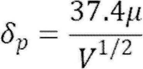
現像促進剤としては、親水性高分子化合物又は親水性低分子化合物であることが好ましい。
本開示において、親水性とは、SP値の極性項の値が6.0~26.0であることをいい、親水性高分子化合物とは分子量(分子量分布を有する場合は重量平均分子量)が3,000以上の化合物をいい、親水性低分子化合物とは分子量(分子量分布を有する場合は重量平均分子量)が3,000未満の化合物をいう。
本開示において、親水性とは、SP値の極性項の値が6.0~26.0であることをいい、親水性高分子化合物とは分子量(分子量分布を有する場合は重量平均分子量)が3,000以上の化合物をいい、親水性低分子化合物とは分子量(分子量分布を有する場合は重量平均分子量)が3,000未満の化合物をいう。
親水性高分子化合物としては、セルロース化合物等が挙げられ、セルロース化合物が好ましい。
セルロース化合物としては、セルロース、又は、セルロースの少なくとも一部が変性された化合物(変性セルロース化合物)が挙げられ、変性セルロース化合物が好ましい。
変性セルロース化合物としては、セルロースのヒドロキシ基の少なくとも一部が、アルキル基及びヒドロキシアルキル基よりなる群から選ばれた少なくとも一種の基により置換された化合物が好ましく挙げられる。
上記セルロースのヒドロキシ基の少なくとも一部が、アルキル基及びヒドロキシアルキル基よりなる群から選ばれた少なくとも一種の基により置換された化合物の置換度は、0.1~6.0であることが好ましく、1~4であることがより好ましい。
変性セルロース化合物としては、アルキルセルロース化合物又はヒドロキシアルキルセルロース化合物が好ましく、ヒドロキシアルキルセルロース化合物がより好ましい。
アルキルセルロース化合物としては、メチルセルロースが好ましく挙げられる。
ヒドロキシアルキルセルロース化合物としては、ヒドロキシプロピルセルロースが好ましく挙げられる。
セルロース化合物としては、セルロース、又は、セルロースの少なくとも一部が変性された化合物(変性セルロース化合物)が挙げられ、変性セルロース化合物が好ましい。
変性セルロース化合物としては、セルロースのヒドロキシ基の少なくとも一部が、アルキル基及びヒドロキシアルキル基よりなる群から選ばれた少なくとも一種の基により置換された化合物が好ましく挙げられる。
上記セルロースのヒドロキシ基の少なくとも一部が、アルキル基及びヒドロキシアルキル基よりなる群から選ばれた少なくとも一種の基により置換された化合物の置換度は、0.1~6.0であることが好ましく、1~4であることがより好ましい。
変性セルロース化合物としては、アルキルセルロース化合物又はヒドロキシアルキルセルロース化合物が好ましく、ヒドロキシアルキルセルロース化合物がより好ましい。
アルキルセルロース化合物としては、メチルセルロースが好ましく挙げられる。
ヒドロキシアルキルセルロース化合物としては、ヒドロキシプロピルセルロースが好ましく挙げられる。
親水性高分子化合物の分子量(分子量分布を有する場合は重量平均分子量)は、3,000~5,000,000であることが好ましく、5,000~200,000であることがより好ましい。
親水性低分子化合物としては、グリコール化合物、ポリオール化合物、有機アミン化合物、有機スルホン酸化合物、有機スルファミン化合物、有機硫酸化合物、有機ホスホン酸化合物、有機カルボン酸化合物、ベタイン化合物等が挙げられ、ポリオール化合物、有機スルホン酸化合物又はベタイン化合物が好ましい。
グリコール化合物としては、エチレングリコール、ジエチレングリコール、トリエチレングリコール、プロピレングリコール、ジプロピレングリコール、トリプロピレングリコール等のグリコール類及びこれらの化合物のエーテル又はエステル誘導体類が挙げられる。
ポリオール化合物としては、グリセリン、ペンタエリスリトール、トリス(2-ヒドロキシエチル)イソシアヌレート等が挙げられる。
有機アミン化合物としては、トリエタノールアミン、ジエタノールアミン、モノエタノールアミン等及びその塩が挙げられる。
有機スルホン酸化合物としては、アルキルスルホン酸、トルエンスルホン酸、ベンゼンスルホン酸等及びその塩が挙げられ、アルキル基の炭素数が1~10のアルキルスルホン酸が好ましく挙げられる。
有機スルファミン化合物としては、アルキルスルファミン酸等及びその塩が挙げられる。
有機硫酸化合物としては、アルキル硫酸、アルキルエーテル硫酸等及びその塩が挙げられる。
有機ホスホン酸化合物としては、フェニルホスホン酸等及びその塩、が挙げられる。
有機カルボン酸化合物としては、酒石酸、シュウ酸、クエン酸、リンゴ酸、乳酸、グルコン酸等及びその塩が挙げられる。
ベタイン化合物としては、ホスホベタイン化合物、スルホベタイン化合物、カルボキシベタイン化合物等が挙げられ、トリメチルグリシンが好ましく挙げられる。
ポリオール化合物としては、グリセリン、ペンタエリスリトール、トリス(2-ヒドロキシエチル)イソシアヌレート等が挙げられる。
有機アミン化合物としては、トリエタノールアミン、ジエタノールアミン、モノエタノールアミン等及びその塩が挙げられる。
有機スルホン酸化合物としては、アルキルスルホン酸、トルエンスルホン酸、ベンゼンスルホン酸等及びその塩が挙げられ、アルキル基の炭素数が1~10のアルキルスルホン酸が好ましく挙げられる。
有機スルファミン化合物としては、アルキルスルファミン酸等及びその塩が挙げられる。
有機硫酸化合物としては、アルキル硫酸、アルキルエーテル硫酸等及びその塩が挙げられる。
有機ホスホン酸化合物としては、フェニルホスホン酸等及びその塩、が挙げられる。
有機カルボン酸化合物としては、酒石酸、シュウ酸、クエン酸、リンゴ酸、乳酸、グルコン酸等及びその塩が挙げられる。
ベタイン化合物としては、ホスホベタイン化合物、スルホベタイン化合物、カルボキシベタイン化合物等が挙げられ、トリメチルグリシンが好ましく挙げられる。
親水性低分子化合物の分子量(分子量分布を有する場合は重量平均分子量)は、100以上3,000未満であることが好ましく、300~2,500であることがより好ましい。
現像促進剤は、環状構造を有する化合物であることが好ましい。
環状構造としては、特に限定されないが、ヒドロキシ基の少なくとも一部が置換されていてもよいグルコース環、イソシアヌル環、ヘテロ原子を有していてもよい芳香環、ヘテロ原子を有していてもよい脂肪族環等が挙げられ、グルコース環又はイソシアヌル環が好ましく挙げられる。
グルコース環を有する化合物としては、上述のセルロース化合物が挙げられる。
イソシアヌル環を有する化合物としては、上述のトリス(2-ヒドロキシエチル)イソシアヌレート等が挙げられる。
芳香環を有する化合物としては、上述のトルエンスルホン酸、ベンゼンスルホン酸等が挙げられる。
脂肪族環を有する化合物としては、上述のアルキル硫酸であって、アルキル基が環構造を有する化合物等が挙げられる。
環状構造としては、特に限定されないが、ヒドロキシ基の少なくとも一部が置換されていてもよいグルコース環、イソシアヌル環、ヘテロ原子を有していてもよい芳香環、ヘテロ原子を有していてもよい脂肪族環等が挙げられ、グルコース環又はイソシアヌル環が好ましく挙げられる。
グルコース環を有する化合物としては、上述のセルロース化合物が挙げられる。
イソシアヌル環を有する化合物としては、上述のトリス(2-ヒドロキシエチル)イソシアヌレート等が挙げられる。
芳香環を有する化合物としては、上述のトルエンスルホン酸、ベンゼンスルホン酸等が挙げられる。
脂肪族環を有する化合物としては、上述のアルキル硫酸であって、アルキル基が環構造を有する化合物等が挙げられる。
また、上記環状構造を有する化合物は、ヒドロキシ基を有することが好ましい。
ヒドロキシ基を有し、かつ、環状構造を有する化合物としては、上述のセルロース化合物、及び、上述のトリス(2-ヒドロキシエチル)イソシアヌレートが好ましく挙げられる。
ヒドロキシ基を有し、かつ、環状構造を有する化合物としては、上述のセルロース化合物、及び、上述のトリス(2-ヒドロキシエチル)イソシアヌレートが好ましく挙げられる。
また、現像促進剤としては、オニウム化合物であることが好ましい。
オニウム化合物としては、アンモニウム化合物、スルホニウム化合物等が挙げられ、アンモニウム化合物が好ましい。
オニウム化合物である現像促進剤としては、トリメチルグリシン等が挙げられる。
また、上記電子受容型重合開始剤におけるオニウム化合物はSP値の極性項の値が6.0~26.0ではない化合物であり、現像促進剤には含まれない。
オニウム化合物としては、アンモニウム化合物、スルホニウム化合物等が挙げられ、アンモニウム化合物が好ましい。
オニウム化合物である現像促進剤としては、トリメチルグリシン等が挙げられる。
また、上記電子受容型重合開始剤におけるオニウム化合物はSP値の極性項の値が6.0~26.0ではない化合物であり、現像促進剤には含まれない。
画像記録層は、現像促進剤を1種単独で含有してもよいし、2種以上を併用してもよい。
本開示において用いられる画像記録層の好ましい態様の一つは、現像促進剤として、2種以上の化合物を含有する態様である。
具体的には、本開示において用いられる画像記録層は、機上現像性及び着肉性の観点から、現像促進剤として、上記ポリオール化合物及び上記ベタイン化合物、上記ベタイン化合物及び上記有機スルホン酸化合物、又は、上記ポリオール化合物及び上記有機スルホン酸化合物を含むことが好ましい。
本開示において用いられる画像記録層の好ましい態様の一つは、現像促進剤として、2種以上の化合物を含有する態様である。
具体的には、本開示において用いられる画像記録層は、機上現像性及び着肉性の観点から、現像促進剤として、上記ポリオール化合物及び上記ベタイン化合物、上記ベタイン化合物及び上記有機スルホン酸化合物、又は、上記ポリオール化合物及び上記有機スルホン酸化合物を含むことが好ましい。
画像記録層の全質量に対する現像促進剤の含有量は、0.1質量%以上20質量%以下であることが好ましく、0.5質量%以上15質量%以下がより好ましく、1質量%以上10質量%以下がより好ましい。
〔その他の成分〕
画像記録層には、その他の成分として、界面活性剤、重合禁止剤、高級脂肪酸誘導体、可塑剤、無機粒子、無機層状化合物等を含有することができる。具体的には、特開2008-284817号公報の段落0114~段落0159の記載を参照することができる。
画像記録層には、その他の成分として、界面活性剤、重合禁止剤、高級脂肪酸誘導体、可塑剤、無機粒子、無機層状化合物等を含有することができる。具体的には、特開2008-284817号公報の段落0114~段落0159の記載を参照することができる。
〔画像記録層の形成〕
本開示に係る平版印刷版原版における画像記録層は、例えば、特開2008-195018号公報の段落0142~段落0143に記載のように、必要な上記各成分を公知の溶剤に分散又は溶解して塗布液を調製し、塗布液を支持体上にバーコーター塗布など公知の方法で塗布し、乾燥することにより形成することができる。塗布、乾燥後における画像記録層の塗布量(固形分)は、用途によって異なるが、0.3g/m2~3.0g/m2が好ましい。この範囲で、良好な感度と画像記録層の良好な皮膜特性が得られる。
溶剤としては、公知の溶剤を用いることができる。具体的には、例えば、水、アセトン、メチルエチルケトン(2-ブタノン)、シクロヘキサン、酢酸エチル、エチレンジクロライド、テトラヒドロフラン、トルエン、エチレングリコールモノメチルエーテル、エチレングリコールモノエチルエーテル、エチレングリコールジメチルエーテル、プロピレングリコールモノメチルエーテル、プロピレングリコールモノエチルエーテル、アセチルアセトン、シクロヘキサノン、ジアセトンアルコール、エチレングリコールモノメーチルエーテルアセテート、エチレングリコールエチルエーテルアセテート、エチレングリコールモノイソプロピルエーテル、エチレングリコールモノブチルエーテルアセテート、1-メトキシ-2-プロパノール、3-メトキシ-1-プロパノール、メトキシメトキシエタノール、ジエチレングリコールモノメチルエーテル、ジエチレングリコールモノエチルエーテル、ジエチレングリコールジメチルエーテル、ジエチレングリコールジエチルエーテル、プロピレングリコールモノメチルエーテルアセテート、プロピレングリコールモノエチルエーテルアセテート、3-メトキシプロピルアセテート、N,N-ジメチルホルムアミド、ジメチルスルホキシド、γ-ブチロラクトン、乳酸メチル、乳酸エチル等が挙げられる。溶剤は、1種単独で使用してもよいし、2種以上を併用してもよい。塗布液中の固形分濃度は1質量%~50質量%であることが好ましい。
塗布、乾燥後における画像記録層の塗布量(固形分)は、用途によって異なるが、良好な感度と画像記録層の良好な皮膜特性を得る観点から、0.3g/m2~3.0g/m2が好ましい。
また、本開示に係る平版印刷版原版における画像記録層の膜厚は、0.1μm~3.0μmであることが好ましく、0.3μm~2.0μmであることがより好ましい。
本開示において、平版印刷版原版における各層の膜厚は、平版印刷版原版の表面に対して垂直な方向に切断した切片を作製し、上記切片の断面を走査型顕微鏡(SEM)により観察することにより確認される。
本開示に係る平版印刷版原版における画像記録層は、例えば、特開2008-195018号公報の段落0142~段落0143に記載のように、必要な上記各成分を公知の溶剤に分散又は溶解して塗布液を調製し、塗布液を支持体上にバーコーター塗布など公知の方法で塗布し、乾燥することにより形成することができる。塗布、乾燥後における画像記録層の塗布量(固形分)は、用途によって異なるが、0.3g/m2~3.0g/m2が好ましい。この範囲で、良好な感度と画像記録層の良好な皮膜特性が得られる。
溶剤としては、公知の溶剤を用いることができる。具体的には、例えば、水、アセトン、メチルエチルケトン(2-ブタノン)、シクロヘキサン、酢酸エチル、エチレンジクロライド、テトラヒドロフラン、トルエン、エチレングリコールモノメチルエーテル、エチレングリコールモノエチルエーテル、エチレングリコールジメチルエーテル、プロピレングリコールモノメチルエーテル、プロピレングリコールモノエチルエーテル、アセチルアセトン、シクロヘキサノン、ジアセトンアルコール、エチレングリコールモノメーチルエーテルアセテート、エチレングリコールエチルエーテルアセテート、エチレングリコールモノイソプロピルエーテル、エチレングリコールモノブチルエーテルアセテート、1-メトキシ-2-プロパノール、3-メトキシ-1-プロパノール、メトキシメトキシエタノール、ジエチレングリコールモノメチルエーテル、ジエチレングリコールモノエチルエーテル、ジエチレングリコールジメチルエーテル、ジエチレングリコールジエチルエーテル、プロピレングリコールモノメチルエーテルアセテート、プロピレングリコールモノエチルエーテルアセテート、3-メトキシプロピルアセテート、N,N-ジメチルホルムアミド、ジメチルスルホキシド、γ-ブチロラクトン、乳酸メチル、乳酸エチル等が挙げられる。溶剤は、1種単独で使用してもよいし、2種以上を併用してもよい。塗布液中の固形分濃度は1質量%~50質量%であることが好ましい。
塗布、乾燥後における画像記録層の塗布量(固形分)は、用途によって異なるが、良好な感度と画像記録層の良好な皮膜特性を得る観点から、0.3g/m2~3.0g/m2が好ましい。
また、本開示に係る平版印刷版原版における画像記録層の膜厚は、0.1μm~3.0μmであることが好ましく、0.3μm~2.0μmであることがより好ましい。
本開示において、平版印刷版原版における各層の膜厚は、平版印刷版原版の表面に対して垂直な方向に切断した切片を作製し、上記切片の断面を走査型顕微鏡(SEM)により観察することにより確認される。
<オーバーコート層>
本開示に係る平版印刷版原版は、画像記録層の、支持体側とは反対の側の面上にオーバーコート層(「保護層」と呼ばれることもある。)を有していてもよい。
上記オーバーコート層の膜厚は、上記画像記録層の膜厚よりも厚いことが好ましい。
オーバーコート層は酸素遮断により画像形成阻害反応を抑制する機能の他、画像記録層における傷の発生防止及び高照度レーザー露光時のアブレーション防止の機能を有する。
本開示に係る平版印刷版原版は、画像記録層の、支持体側とは反対の側の面上にオーバーコート層(「保護層」と呼ばれることもある。)を有していてもよい。
上記オーバーコート層の膜厚は、上記画像記録層の膜厚よりも厚いことが好ましい。
オーバーコート層は酸素遮断により画像形成阻害反応を抑制する機能の他、画像記録層における傷の発生防止及び高照度レーザー露光時のアブレーション防止の機能を有する。
このような特性のオーバーコート層については、例えば、米国特許第3,458,311号明細書及び特公昭55-49729号公報に記載されている。オーバーコート層に用いられる酸素低透過性のポリマーとしては、水溶性ポリマー、水不溶性ポリマーのいずれをも適宜選択して使用することができ、必要に応じて2種類以上を混合して使用することもできるが、機上現像性の観点から、水溶性ポリマーを含むことが好ましい。
本開示において、水溶性ポリマーとは、70℃、100gの純水に対して1g以上溶解し、かつ、70℃、100gの純水に対して1gのポリマーが溶解した溶液を25℃に冷却しても析出しないポリマーをいう。
オーバーコート層において用いられる水溶性ポリマーとしては、例えば、ポリビニルアルコール、変性ポリビニルアルコール、ポリビニルピロリドン、水溶性セルロース誘導体、ポリエチレングリコール、ポリ(メタ)アクリロニトリル等が挙げられる。
変性ポリビニルアルコールとしてはカルボキシ基又はスルホ基を有する酸変性ポリビニルアルコールが好ましく用いられる。具体的には、特開2005-250216号公報及び特開2006-259137号公報に記載の変性ポリビニルアルコールが挙げられる。
本開示において、水溶性ポリマーとは、70℃、100gの純水に対して1g以上溶解し、かつ、70℃、100gの純水に対して1gのポリマーが溶解した溶液を25℃に冷却しても析出しないポリマーをいう。
オーバーコート層において用いられる水溶性ポリマーとしては、例えば、ポリビニルアルコール、変性ポリビニルアルコール、ポリビニルピロリドン、水溶性セルロース誘導体、ポリエチレングリコール、ポリ(メタ)アクリロニトリル等が挙げられる。
変性ポリビニルアルコールとしてはカルボキシ基又はスルホ基を有する酸変性ポリビニルアルコールが好ましく用いられる。具体的には、特開2005-250216号公報及び特開2006-259137号公報に記載の変性ポリビニルアルコールが挙げられる。
上記水溶性ポリマーの中でも、ポリビニルアルコールを含むことが好ましく、けん化度が50%以上であるポリビニルアルコールを含むことが更に好ましい。
上記けん化度は、60%以上が好ましく、70%以上がより好ましく、85%以上が更に好ましい。けん化度の上限は特に限定されず、100%以下であればよい。
上記けん化度は、JIS K 6726:1994に記載の方法に従い測定される。
また、オーバーコート層の一態様として、ポリビニルアルコールと、ポリエチレングリコールとを含む態様も好ましく挙げられる。
上記けん化度は、60%以上が好ましく、70%以上がより好ましく、85%以上が更に好ましい。けん化度の上限は特に限定されず、100%以下であればよい。
上記けん化度は、JIS K 6726:1994に記載の方法に従い測定される。
また、オーバーコート層の一態様として、ポリビニルアルコールと、ポリエチレングリコールとを含む態様も好ましく挙げられる。
本開示におけるオーバーコート層が水溶性ポリマーを含む場合、オーバーコート層の全質量に対する水溶性ポリマーの含有量は、1質量%~99質量%であることが好ましく、3質量%~97質量%であることがより好ましく、5質量%~95質量%であることが更に好ましい。
オーバーコート層は、酸素遮断性を高めるために無機層状化合物を含有してもよい。無機層状化合物は、薄い平板状の形状を有する粒子であり、例えば、天然雲母、合成雲母等の雲母群、式:3MgO・4SiO・H2Oで表されるタルク、テニオライト、モンモリロナイト、サポナイト、ヘクトライト、リン酸ジルコニウム等が挙げられる。
好ましく用いられる無機層状化合物は雲母化合物である。雲母化合物としては、例えば、式:A(B,C)2-5D4O10(OH,F,O)2〔ただし、Aは、K、Na、Caのいずれか、B及びCは、Fe(II)、Fe(III)、Mn、Al、Mg、Vのいずれかであり、Dは、Si又はAlである。〕で表される天然雲母、合成雲母等の雲母群が挙げられる。
好ましく用いられる無機層状化合物は雲母化合物である。雲母化合物としては、例えば、式:A(B,C)2-5D4O10(OH,F,O)2〔ただし、Aは、K、Na、Caのいずれか、B及びCは、Fe(II)、Fe(III)、Mn、Al、Mg、Vのいずれかであり、Dは、Si又はAlである。〕で表される天然雲母、合成雲母等の雲母群が挙げられる。
雲母群においては、天然雲母としては白雲母、ソーダ雲母、金雲母、黒雲母及び鱗雲母が挙げられる。合成雲母としてはフッ素金雲母KMg3(AlSi3O10)F2、カリ四ケイ素雲母KMg2.5Si4O10)F2等の非膨潤性雲母、及び、NaテトラシリリックマイカNaMg2.5(Si4O10)F2、Na又はLiテニオライト(Na,Li)Mg2Li(Si4O10)F2、モンモリロナイト系のNa又はLiヘクトライト(Na,Li)1/8Mg2/5Li1/8(Si4O10)F2等の膨潤性雲母等が挙げられる。更に合成スメクタイトも有用である。
上記の雲母化合物の中でも、フッ素系の膨潤性雲母が特に有用である。すなわち、膨潤性合成雲母は、10Å~15Å(1Å=0.1nm)程度の厚さの単位結晶格子層からなる積層構造を有し、格子内金属原子置換が他の粘土鉱物より著しく大きい。その結果、格子層は正電荷不足を生じ、それを補償するために層間にLi+、Na+、Ca2+、Mg2+等の陽イオンを吸着している。これらの層間に介在している陽イオンは交換性陽イオンと呼ばれ、いろいろな陽イオンと交換し得る。特に、層間の陽イオンがLi+、Na+の場合、イオン半径が小さいため層状結晶格子間の結合が弱く、水により大きく膨潤する。その状態でシェアーをかけると容易に劈開し、水中で安定したゾルを形成する。膨潤性合成雲母はこの傾向が強く、特に好ましく用いられる。
雲母化合物の形状としては、拡散制御の観点からは、厚さは薄ければ薄いほどよく、平面サイズは塗布面の平滑性や活性光線の透過性を阻害しない限りにおいて大きい程よい。従って、アスペクト比は、好ましくは20以上であり、より好ましくは100以上、特に好ましくは200以上である。アスペクト比は粒子の厚さに対する長径の比であり、例えば、粒子の顕微鏡写真による投影図から測定することができる。アスペクト比が大きい程、得られる効果が大きい。
雲母化合物の粒子径は、その平均長径が、好ましくは0.3μm~20μm、より好ましくは0.5μm~10μm、特に好ましくは1μm~5μmである。粒子の平均の厚さは、好ましくは0.1μm以下、より好ましくは0.05μm以下、特に好ましくは0.01μm以下である。具体的には、例えば、代表的化合物である膨潤性合成雲母の場合、好ましい態様としては、厚さが1nm~50nm程度、面サイズ(長径)が1μm~20μm程度である。
無機層状化合物の含有量は、オーバーコート層の全質量に対して、1質量%~60質量%が好ましく、3質量%~50質量%がより好ましい。複数種の無機層状化合物を併用する場合でも、無機層状化合物の合計量が上記の含有量であることが好ましい。上記範囲で酸素遮断性が向上し、良好な感度が得られる。また、着肉性の低下を防止できる。
オーバーコート層は可撓性付与のための可塑剤、塗布性を向上させための界面活性剤、表面の滑り性を制御するための無機粒子など公知の添加物を含有してもよい。また、画像記録層において記載した感脂化剤をオーバーコート層に含有させてもよい。
オーバーコート層は公知の方法で塗布される。オーバーコート層の塗布量(固形分)は、0.01g/m2~10g/m2が好ましく、0.02g/m2~3g/m2がより好ましく、0.02g/m2~1g/m2が特に好ましい。
本開示に係る平版印刷版原版におけるオーバーコート層の膜厚は、0.1μm~5.0μmであることが好ましく、0.3μm~4.0μmであることがより好ましい。
本開示に係る平版印刷版原版におけるオーバーコート層の膜厚は、上記画像記録層の膜厚に対し、1.1倍~5.0倍であることが好ましく、1.5倍~3.0倍であることがより好ましい。
本開示に係る平版印刷版原版におけるオーバーコート層の膜厚は、0.1μm~5.0μmであることが好ましく、0.3μm~4.0μmであることがより好ましい。
本開示に係る平版印刷版原版におけるオーバーコート層の膜厚は、上記画像記録層の膜厚に対し、1.1倍~5.0倍であることが好ましく、1.5倍~3.0倍であることがより好ましい。
<支持体>
本開示に係る平版印刷版原版は、支持体を有する。
支持体としては、親水性表面を有する支持体(「親水性支持体」ともいう。)が好ましい。親水性表面としては、水との接触角が10°より小さいものが好ましく、5°より小さいものがより好ましい。
本開示における水接触角は、協和界面化学(株)製DM-501によって、25℃における表面上の水滴の接触角(0.2秒後)として測定される。
本開示に係る平版印刷版原版の支持体は、公知の平版印刷版原版用支持体から適宜選択して用いることができる。支持体としては、公知の方法で粗面化処理され、陽極酸化処理されたアルミニウム板が好ましい。
以下、本開示に係る平版印刷版原版に用いられる支持体について図面を用いて説明するが、図面の説明中、符号が省略される場合がある。
本開示に係る平版印刷版原版は、支持体を有する。
支持体としては、親水性表面を有する支持体(「親水性支持体」ともいう。)が好ましい。親水性表面としては、水との接触角が10°より小さいものが好ましく、5°より小さいものがより好ましい。
本開示における水接触角は、協和界面化学(株)製DM-501によって、25℃における表面上の水滴の接触角(0.2秒後)として測定される。
本開示に係る平版印刷版原版の支持体は、公知の平版印刷版原版用支持体から適宜選択して用いることができる。支持体としては、公知の方法で粗面化処理され、陽極酸化処理されたアルミニウム板が好ましい。
以下、本開示に係る平版印刷版原版に用いられる支持体について図面を用いて説明するが、図面の説明中、符号が省略される場合がある。
陽極酸化被膜の厚さは、200nm~2,000nmであることが好ましい。
陽極酸化皮膜を有するアルミニウム支持体の一実施形態の模式的断面図を図2Aに示す。図2Aにおいて、陽極酸化皮膜を有するアルミニウム支持体12は、アルミニウム板18とアルミニウムの陽極酸化皮膜20(以後、単に「陽極酸化皮膜20」とも称する)とをこの順に有する。アルミニウム支持体12中の陽極酸化皮膜20は、図1における平版印刷版原版10の画像記録層16側に位置する。即ち、平版印刷版原版10は、アルミニウム板18、陽極酸化皮膜20、下塗り層14、及び、画像記録層16を有する。
陽極酸化皮膜を有するアルミニウム支持体の一実施形態の模式的断面図を図2Aに示す。図2Aにおいて、陽極酸化皮膜を有するアルミニウム支持体12は、アルミニウム板18とアルミニウムの陽極酸化皮膜20(以後、単に「陽極酸化皮膜20」とも称する)とをこの順に有する。アルミニウム支持体12中の陽極酸化皮膜20は、図1における平版印刷版原版10の画像記録層16側に位置する。即ち、平版印刷版原版10は、アルミニウム板18、陽極酸化皮膜20、下塗り層14、及び、画像記録層16を有する。
〔アルミニウム板〕
アルミニウム板(アルミニウム支持体)は、寸度的に安定なアルミニウムを主成分とする金属、即ち、アルミニウムまたはアルミニウム合金からなる。アルミニウム板は、純アルミニウム板又はアルミニウムを主成分とし微量の異元素を含む合金板からなる。
アルミニウム板(アルミニウム支持体)は、寸度的に安定なアルミニウムを主成分とする金属、即ち、アルミニウムまたはアルミニウム合金からなる。アルミニウム板は、純アルミニウム板又はアルミニウムを主成分とし微量の異元素を含む合金板からなる。
アルミニウム合金に含まれる異元素には、ケイ素、鉄、マンガン、銅、マグネシウム、クロム、亜鉛、ビスマス、ニッケル、チタンなどがある。合金中の異元素の含有量は10質量%以下である。アルミニウム板としては、純アルミニウム板が好適であるが、完全に純粋なアルミニウムは製錬技術上製造が困難であるので、僅かに異元素を含むものでもよい。アルミニウム板18としては、その組成が限定されるものではなく、公知公用の素材のもの(例えばJIS A 1050、JIS A 1100、JIS A 3103、及び、JIS A 3005)を適宜利用することができる。
アルミニウム板の幅は400mm~2,000mm程度、厚さはおよそ0.1mm~0.6mm程度が好ましい。この幅又は厚さは、印刷機の大きさ、印刷版の大きさ、及び、ユーザーの希望により適宜変更できる。
本開示に係る平版印刷版原版に用いられる支持体は、画像記録層側の表面にマイクロポアを有することが好ましく、画像記録層側の表面に陽極酸化被膜を有し、陽極酸化被膜表面に、マイクロポアを有することが好ましい。
平版印刷版原版の画像記録層において、上記赤外線吸収剤と、上記重合開始剤と、上記重合性化合物と、上記熱可塑性樹脂粒子とを併用することによって、熱可塑性樹脂粒子同士の熱融着に加えて、熱可塑性樹脂粒子の熱融着物と混ざり合いながら重合性化合物が重合することにより、より強固な膜が形成されるとともに、陽極酸化被膜表面にマイクロポアを有することで、マイクロポア内でも重合性化合物の上記と同様の重合によって支持体と画像記録層との密着性が向上されることにより、UV耐刷性に優れると推定している。
上記表面におけるマイクロポアの平均径は、UV耐刷性の観点から、13nmを超え100nm以下であることが好ましく、15nm~80nmであることがより好ましく、20nm~60nmであることがより好ましい。
本開示において、マイクロポアという用語は、支持体の画像記録層側の表面に形成されたポア、具体的には、陽極酸化皮膜中のポアを表す一般的に使われる用語であり、ポアのサイズを規定するものではない。
平版印刷版原版の画像記録層において、上記赤外線吸収剤と、上記重合開始剤と、上記重合性化合物と、上記熱可塑性樹脂粒子とを併用することによって、熱可塑性樹脂粒子同士の熱融着に加えて、熱可塑性樹脂粒子の熱融着物と混ざり合いながら重合性化合物が重合することにより、より強固な膜が形成されるとともに、陽極酸化被膜表面にマイクロポアを有することで、マイクロポア内でも重合性化合物の上記と同様の重合によって支持体と画像記録層との密着性が向上されることにより、UV耐刷性に優れると推定している。
上記表面におけるマイクロポアの平均径は、UV耐刷性の観点から、13nmを超え100nm以下であることが好ましく、15nm~80nmであることがより好ましく、20nm~60nmであることがより好ましい。
本開示において、マイクロポアという用語は、支持体の画像記録層側の表面に形成されたポア、具体的には、陽極酸化皮膜中のポアを表す一般的に使われる用語であり、ポアのサイズを規定するものではない。
〔陽極酸化皮膜〕
本開示に係る平版印刷版原版に用いられる支持体は、画像記録層側の表面に陽極酸化被膜を有することが好ましい。
図2Aにおいて、陽極酸化皮膜20は、陽極酸化処理によってアルミニウム板18の表面に一般的に作製される、皮膜表面に略垂直であり、個々が均一に分布した極微細なマイクロポア22を有する陽極酸化アルミニウム皮膜を指す。マイクロポア22は、陽極酸化皮膜表面から厚み方向(アルミニウム板18側)に沿ってのびている。
陽極酸化皮膜の厚さX1は、200nm~2,000nmであることが好ましく、より好ましくは500nm~1,800nm、更に好ましくは750nm~1,500nmである。
本開示に係る平版印刷版原版に用いられる支持体は、画像記録層側の表面に陽極酸化被膜を有することが好ましい。
図2Aにおいて、陽極酸化皮膜20は、陽極酸化処理によってアルミニウム板18の表面に一般的に作製される、皮膜表面に略垂直であり、個々が均一に分布した極微細なマイクロポア22を有する陽極酸化アルミニウム皮膜を指す。マイクロポア22は、陽極酸化皮膜表面から厚み方向(アルミニウム板18側)に沿ってのびている。
陽極酸化皮膜の厚さX1は、200nm~2,000nmであることが好ましく、より好ましくは500nm~1,800nm、更に好ましくは750nm~1,500nmである。
本開示に係る平版印刷版原版に用いられるアルミニウム支持体は、下記態様1~態様3のいずれかの態様であることが好ましい。
(態様1)
上記マイクロポアが、上記陽極酸化皮膜表面から深さ10nmを超える位置までのびており、上記陽極酸化皮膜表面におけるマイクロポアの平均径に対する、マイクロポア底部の平均径の割合が0.8倍以上1.2倍以下である。
(態様2)
上記マイクロポアが、上記陽極酸化皮膜表面から深さ10nm~1,000nmの位置までのびる大径孔部と、上記大径孔部の底部と連通し、連通位置から深さ方向に20nm~2,000nmの位置までのびる小径孔部と、から構成され、上記大径孔部の平均径が、13nmを超え100nm以下であり、上記小径孔部の平均径が、上記大径孔部の平均径の5%~80%である。
(態様3)
上記陽極酸化皮膜表面における上記マイクロポアの平均径が10nm~30nm以下であり、内部の最大径の平均値が20nm~300nmであり、上記内部の最大径の平均値が上記陽極酸化皮膜表面における上記マイクロポアの平均径よりも大きい。
以下、それぞれの態様について図面を用いて説明する。
上記マイクロポアが、上記陽極酸化皮膜表面から深さ10nmを超える位置までのびており、上記陽極酸化皮膜表面におけるマイクロポアの平均径に対する、マイクロポア底部の平均径の割合が0.8倍以上1.2倍以下である。
(態様2)
上記マイクロポアが、上記陽極酸化皮膜表面から深さ10nm~1,000nmの位置までのびる大径孔部と、上記大径孔部の底部と連通し、連通位置から深さ方向に20nm~2,000nmの位置までのびる小径孔部と、から構成され、上記大径孔部の平均径が、13nmを超え100nm以下であり、上記小径孔部の平均径が、上記大径孔部の平均径の5%~80%である。
(態様3)
上記陽極酸化皮膜表面における上記マイクロポアの平均径が10nm~30nm以下であり、内部の最大径の平均値が20nm~300nmであり、上記内部の最大径の平均値が上記陽極酸化皮膜表面における上記マイクロポアの平均径よりも大きい。
以下、それぞれの態様について図面を用いて説明する。
〔態様1について〕
図2Aは、上記態様1の一実施形態を示す断面概略図である。
図2Aにおいて、マイクロポア22が、陽極酸化皮膜20表面から深さ10nmを超える位置までのびており、上記陽極酸化皮膜表面におけるマイクロポアの平均径に対する、マイクロポア底部の平均径の割合が0.8倍以上1.2倍以下である。
マイクロポア22の深さX2は10nmを超え、50nm以上であることが好ましく、75nm以上であることがより好ましい。
上記マイクロポア22の深さX2は、陽極酸化皮膜20の断面をFE-SEMで観察し(15万倍)、得られた画像において、25個のマイクロポアの深さを測定し、算術平均値として求められる。
図2Aは、上記態様1の一実施形態を示す断面概略図である。
図2Aにおいて、マイクロポア22が、陽極酸化皮膜20表面から深さ10nmを超える位置までのびており、上記陽極酸化皮膜表面におけるマイクロポアの平均径に対する、マイクロポア底部の平均径の割合が0.8倍以上1.2倍以下である。
マイクロポア22の深さX2は10nmを超え、50nm以上であることが好ましく、75nm以上であることがより好ましい。
上記マイクロポア22の深さX2は、陽極酸化皮膜20の断面をFE-SEMで観察し(15万倍)、得られた画像において、25個のマイクロポアの深さを測定し、算術平均値として求められる。
上記陽極酸化皮膜表面におけるマイクロポア22の平均径Y1は、13nmを超え100nm以下であることが好ましく、15nm以上75nm以下であることがより好ましく、20nm以上50nm以下であることが更に好ましい。
上記陽極酸化皮膜表面におけるマイクロポア22の、深さX2に対する平均径Y1の割合(X2/Y1)は、2倍以上10倍以下が好ましく、2.5倍以上7倍以下がより好ましく、3倍以上6倍以下が更に好ましい。
また、マイクロポア22の底部の平均径Y2は、10nm以上100nm以下であることが好ましく、15nm以上75nm以下であることがより好ましく、20nm以上50nm以下であることが更に好ましい。
陽極酸化皮膜表面におけるマイクロポア22の平均径Y1に対する、マイクロポア22底部の平均径Y2の割合は、0.8倍以上1.2倍以下であることが好ましく、0.85倍以上1.15倍以下であることがより好ましく、0.9倍以上1.1倍以下であることが更に好ましい。
陽極酸化皮膜表面におけるマイクロポア22の平均径Y1に対する、マイクロポア22の底部の平均径Y2の割合は、下記式1Aにより求められる値である。
式1A:(陽極酸化皮膜表面におけるマイクロポア22の平均径Y1)/(マイクロポア22の底部の平均径Y2)
上記陽極酸化皮膜表面におけるマイクロポア22の、深さX2に対する平均径Y1の割合(X2/Y1)は、2倍以上10倍以下が好ましく、2.5倍以上7倍以下がより好ましく、3倍以上6倍以下が更に好ましい。
また、マイクロポア22の底部の平均径Y2は、10nm以上100nm以下であることが好ましく、15nm以上75nm以下であることがより好ましく、20nm以上50nm以下であることが更に好ましい。
陽極酸化皮膜表面におけるマイクロポア22の平均径Y1に対する、マイクロポア22底部の平均径Y2の割合は、0.8倍以上1.2倍以下であることが好ましく、0.85倍以上1.15倍以下であることがより好ましく、0.9倍以上1.1倍以下であることが更に好ましい。
陽極酸化皮膜表面におけるマイクロポア22の平均径Y1に対する、マイクロポア22の底部の平均径Y2の割合は、下記式1Aにより求められる値である。
式1A:(陽極酸化皮膜表面におけるマイクロポア22の平均径Y1)/(マイクロポア22の底部の平均径Y2)
陽極酸化皮膜表面におけるマイクロポアの平均径Y1は、陽極酸化皮膜20の表面を倍率15万倍の電界放出型走査電子顕微鏡(FE-SEM)でN=4枚観察し、得られた4枚の画像において、400nm×600nmの範囲に存在するマイクロポアの径(直径)を測定し、算術平均値として求められる。
陽極酸化皮膜表面におけるマイクロポアの形状(開口部の形状)が円状でない場合は、円相当径を用いる。
マイクロポア22の底部の平均径Y2は、陽極酸化皮膜20表面を倍率15万倍のFE-SEMでN=4枚観察し、得られた4枚の画像において、400nm×600nmの範囲に存在するマイクロポア22の底部の径(直径)を測定し、算術平均値として求められる。なお、マイクロポア22の深さが深い場合は、必要に応じて、陽極酸化皮膜20上部を陽極酸化被膜と水平に切削し(例えば、アルゴンガスによって切削)、その後陽極酸化皮膜20表面を上記FE-SEMで観察して、マイクロポア22の底部の平均径Y2を求めてもよい。
なお、マイクロポア底部の形状が円状でない場合は、円相当径を用いる。
また、底部の形状が平面状ではない場合、例えば図2Bに記載のY2-1を底部の平均径として測定する。
図2Bは図2A中のマイクロポアの1つを拡大した概略断面図である。
陽極酸化皮膜表面におけるマイクロポアの形状(開口部の形状)が円状でない場合は、円相当径を用いる。
マイクロポア22の底部の平均径Y2は、陽極酸化皮膜20表面を倍率15万倍のFE-SEMでN=4枚観察し、得られた4枚の画像において、400nm×600nmの範囲に存在するマイクロポア22の底部の径(直径)を測定し、算術平均値として求められる。なお、マイクロポア22の深さが深い場合は、必要に応じて、陽極酸化皮膜20上部を陽極酸化被膜と水平に切削し(例えば、アルゴンガスによって切削)、その後陽極酸化皮膜20表面を上記FE-SEMで観察して、マイクロポア22の底部の平均径Y2を求めてもよい。
なお、マイクロポア底部の形状が円状でない場合は、円相当径を用いる。
また、底部の形状が平面状ではない場合、例えば図2Bに記載のY2-1を底部の平均径として測定する。
図2Bは図2A中のマイクロポアの1つを拡大した概略断面図である。
態様1におけるマイクロポア22の形状は特に限定されず、例えば、略直管状(略円柱状)、深さ方向(厚み方向)に向かって径が小さくなる円錐状、深さ方向(厚み方向)に向かって径が大きくなる逆円錐状、中央部の径が大きい円柱状、中央部の径が小さい円柱状等が挙げられ、略直管状が好ましい。マイクロポア22の底部の形状は特に限定されず、曲面状(凹状)であっても、平面状であってもよい。
陽極酸化皮膜表面におけるマイクロポア22の平均径Y1に対する、中央部の径Y1Aの割合は(Y1A/Y1)は、0.8倍以上1.2倍以下であることが好ましい。
マイクロポア22の中央部の平均径Y1Aは、陽極酸化皮膜20表面を倍率15万倍のFE-SEMでN=4枚観察し、得られた4枚の画像において、400nm×600nmの範囲に存在するマイクロポア22の中央部の径(直径)を測定し、算術平均値として求められる。なお、マイクロポア22の深さが深い場合は、必要に応じて、陽極酸化皮膜20上部を陽極酸化被膜と水平に切削し(例えば、アルゴンガスによって切削)、その後陽極酸化皮膜20表面を上記FE-SEMで観察して、マイクロポア22の底部の中央部の径Y1Aを求めてもよい。
陽極酸化皮膜表面におけるマイクロポア22の平均径Y1に対する、中央部の径Y1Aの割合は(Y1A/Y1)は、0.8倍以上1.2倍以下であることが好ましい。
マイクロポア22の中央部の平均径Y1Aは、陽極酸化皮膜20表面を倍率15万倍のFE-SEMでN=4枚観察し、得られた4枚の画像において、400nm×600nmの範囲に存在するマイクロポア22の中央部の径(直径)を測定し、算術平均値として求められる。なお、マイクロポア22の深さが深い場合は、必要に応じて、陽極酸化皮膜20上部を陽極酸化被膜と水平に切削し(例えば、アルゴンガスによって切削)、その後陽極酸化皮膜20表面を上記FE-SEMで観察して、マイクロポア22の底部の中央部の径Y1Aを求めてもよい。
-その他の特性-
陽極酸化被膜20の表面におけるマイクロポア22の密度は、特に限定されないが、陽極酸化被膜の単位面積に対し、200個/μm2~2,000個/μm2であることが好ましく、200個/μm2~1,000個/μm2であることがより好ましい。
上記密度は、陽極酸化皮膜20の表面を倍率15万倍の電界放出型走査電子顕微鏡(FE-SEM)でN=4枚観察し、得られた4枚の画像において、400nm×600nmの範囲に存在するマイクロポアの数を計測し、計測値の算術平均値として算出される。
陽極酸化被膜20の表面におけるマイクロポア22の密度は、特に限定されないが、陽極酸化被膜の単位面積に対し、200個/μm2~2,000個/μm2であることが好ましく、200個/μm2~1,000個/μm2であることがより好ましい。
上記密度は、陽極酸化皮膜20の表面を倍率15万倍の電界放出型走査電子顕微鏡(FE-SEM)でN=4枚観察し、得られた4枚の画像において、400nm×600nmの範囲に存在するマイクロポアの数を計測し、計測値の算術平均値として算出される。
陽極酸化被膜20において、上記マイクロポア22は、陽極酸化被膜の全面に分布していてもよいし、少なくとも一部に分布していてもよいが、全面に分布していることが好ましい。
マイクロポア22は、陽極酸化皮膜表面22に略垂直であることが好ましい。
また、マイクロポア22は、個々が均一に近い状態で分布していることが好ましい。
マイクロポア22は、陽極酸化皮膜表面22に略垂直であることが好ましい。
また、マイクロポア22は、個々が均一に近い状態で分布していることが好ましい。
〔態様2について〕
図3Aは、上記態様2の一実施形態を示す断面概略図である。
陽極酸化皮膜20中のマイクロポア22は、陽極酸化皮膜表面から深さ(深さA:図3A参照)が10nm~1,000nm位置までのびる大径孔部24と、大径孔部24の底部と連通し、連通位置から更に深さ方向にのびる小径孔部26とから構成される。
以下に、大径孔部24と小径孔部26について詳述する。
図3Aは、上記態様2の一実施形態を示す断面概略図である。
陽極酸化皮膜20中のマイクロポア22は、陽極酸化皮膜表面から深さ(深さA:図3A参照)が10nm~1,000nm位置までのびる大径孔部24と、大径孔部24の底部と連通し、連通位置から更に深さ方向にのびる小径孔部26とから構成される。
以下に、大径孔部24と小径孔部26について詳述する。
-大径孔部-
陽極酸化皮膜表面の大径孔部に、支持体と接している本開示における画像記録層が一部入り込むことによって、アンカー効果を発揮して画像部と支持体との密着性が高まり、印刷時における画像部の耐刷性が向上すると推察される。
大径孔部24の陽極酸化皮膜表面におけるマイクロポアの平均径(平均開口径)は、10nm~100nm以下であることが好ましい。UV耐刷性がより優れる点で、マイクロポアの平均径は、13nmを超え100nm以下であることがより好ましく、15nm~60nmが更に好ましく、18nm~40nmが特に好ましい。
上記マイクロポアの平均径が13nmより大きい場合、UV耐刷性に優れた平版印刷版が得られやすい。また、上記マイクロポアの平均径が100nm以下であれば、放置払い性に優れた平版位刷版が得られやすい。
本明細書において、放置払い性に優れるとは、平版印刷版を用いて印刷を行った後に、印刷を中断(例えば、数時間の中断など)して、印刷を再開したときに、汚れが認められない印刷物が得られるまでに要する印刷枚数が少ないことをいう。
大径孔部24の平均径は、陽極酸化皮膜20表面を倍率15万倍の電界放出型走査電子顕微鏡(FE-SEM)でN=4枚観察し、得られた4枚の画像において、400nm×600nmの範囲に存在するマイクロポア(大径孔部)の径(直径)を測定し、算術平均値として求められる。
なお、大径孔部24の形状が円状でない場合は、円相当径を用いる。
陽極酸化皮膜表面の大径孔部に、支持体と接している本開示における画像記録層が一部入り込むことによって、アンカー効果を発揮して画像部と支持体との密着性が高まり、印刷時における画像部の耐刷性が向上すると推察される。
大径孔部24の陽極酸化皮膜表面におけるマイクロポアの平均径(平均開口径)は、10nm~100nm以下であることが好ましい。UV耐刷性がより優れる点で、マイクロポアの平均径は、13nmを超え100nm以下であることがより好ましく、15nm~60nmが更に好ましく、18nm~40nmが特に好ましい。
上記マイクロポアの平均径が13nmより大きい場合、UV耐刷性に優れた平版印刷版が得られやすい。また、上記マイクロポアの平均径が100nm以下であれば、放置払い性に優れた平版位刷版が得られやすい。
本明細書において、放置払い性に優れるとは、平版印刷版を用いて印刷を行った後に、印刷を中断(例えば、数時間の中断など)して、印刷を再開したときに、汚れが認められない印刷物が得られるまでに要する印刷枚数が少ないことをいう。
大径孔部24の平均径は、陽極酸化皮膜20表面を倍率15万倍の電界放出型走査電子顕微鏡(FE-SEM)でN=4枚観察し、得られた4枚の画像において、400nm×600nmの範囲に存在するマイクロポア(大径孔部)の径(直径)を測定し、算術平均値として求められる。
なお、大径孔部24の形状が円状でない場合は、円相当径を用いる。
大径孔部24の底部は、陽極酸化皮膜表面から深さ(以後、「深さA」とも称する場合がある)が10nm~1,000nm位置にあることが好ましい。つまり、大径孔部24は、陽極酸化皮膜表面から深さ方向(厚み方向)に10nm以上のびる孔部であることが好ましい。中でも、本開示の効果がより優れる点で、深さAは、10nmを超え1000nm以下が好ましく、25nm~200nmがより好ましく、70nm~100nmが更に好ましい。
上記深さAが10nm以上であれば、小点耐刷性、小点の現像ラチチュード、及び、ベタ画像部の耐刷性に優れた平版印刷版がより得られやすい。また、上記深さAが1,000n以下であれば、特に放置払い性により優れた平版位刷版が得られやすい。
本明細書において「小点耐刷性」とは、特に小点(例えば、直径(円相当径)が数μm~数十μm等の画像部)の耐刷性を意味する。
上記陽極酸化皮膜表面からの深さは、陽極酸化皮膜20の断面をFE-SEMで観察し(15万倍)、得られた画像において、25個の大径孔部の深さを測定し、算術平均値として求められる。
上記深さAが10nm以上であれば、小点耐刷性、小点の現像ラチチュード、及び、ベタ画像部の耐刷性に優れた平版印刷版がより得られやすい。また、上記深さAが1,000n以下であれば、特に放置払い性により優れた平版位刷版が得られやすい。
本明細書において「小点耐刷性」とは、特に小点(例えば、直径(円相当径)が数μm~数十μm等の画像部)の耐刷性を意味する。
上記陽極酸化皮膜表面からの深さは、陽極酸化皮膜20の断面をFE-SEMで観察し(15万倍)、得られた画像において、25個の大径孔部の深さを測定し、算術平均値として求められる。
大径孔部24の形状は特に限定されず、例えば、略直管状(略円柱状)、深さ方向(厚み方向)に向かって径が小さくなる円錐状、深さ方向(厚み方向)に向かって径が大きくなる逆円錐状が挙げられ、略直管状が好ましい。大径孔部の底部における径は、通常、開口部の径と1nm~10nm程度の差があってもよい。大径孔部24の底部の形状は特に限定されず、曲面状(凹状)であっても、平面状であってもよい。
-小径孔部-
図3Aに示すように、上記マイクロポアは、大径孔部24の底部と連通して、連通位置よりさらに深さ方向(厚み方向)に延びる孔部である、小径孔部26を更に有することが好ましい。
ひとつの小径孔部26は、通常ひとつの大径孔部24と連通するが、2つ以上の小径孔部26がひとつの大径孔部24の底部と連通していてもよい。
小径孔部26の連通位置における平均径は特に限定されないが、大径孔部24の底部と連通における小径孔部26の平均径は、大径孔部24の平均径よりも小さく、20nm未満であることが好ましく、15nm以下がより好ましく、13nm以下が更に好ましく、10nm以下が特に好ましい。平均径は、5nm以上であることが好ましい。平均径が20nm未満の場合、放置払い性に優れた平版印刷版が得られやすい。
図3Aに示すように、上記マイクロポアは、大径孔部24の底部と連通して、連通位置よりさらに深さ方向(厚み方向)に延びる孔部である、小径孔部26を更に有することが好ましい。
ひとつの小径孔部26は、通常ひとつの大径孔部24と連通するが、2つ以上の小径孔部26がひとつの大径孔部24の底部と連通していてもよい。
小径孔部26の連通位置における平均径は特に限定されないが、大径孔部24の底部と連通における小径孔部26の平均径は、大径孔部24の平均径よりも小さく、20nm未満であることが好ましく、15nm以下がより好ましく、13nm以下が更に好ましく、10nm以下が特に好ましい。平均径は、5nm以上であることが好ましい。平均径が20nm未満の場合、放置払い性に優れた平版印刷版が得られやすい。
小径孔部26の平均径は、陽極酸化皮膜20表面を倍率15万倍のFE-SEMでN=4枚観察し、得られた4枚の画像において、400nm×600nmの範囲に存在するマイクロポア(小径孔部)の径(直径)を測定し、算術平均値として求められる。
なお、大径孔部の深さが深い場合は、必要に応じて、陽極酸化皮膜20上部(大径孔部のある領域)を、例えば、アルゴンガス等で切削し、その後陽極酸化皮膜20表面を上記FE-SEMで観察して、小径孔部の平均径を求めてもよい。
なお、小径孔部26の形状が円状でない場合は、円相当径を用いる。
なお、大径孔部の深さが深い場合は、必要に応じて、陽極酸化皮膜20上部(大径孔部のある領域)を、例えば、アルゴンガス等で切削し、その後陽極酸化皮膜20表面を上記FE-SEMで観察して、小径孔部の平均径を求めてもよい。
なお、小径孔部26の形状が円状でない場合は、円相当径を用いる。
小径孔部26の底部は、上記の大径孔部24との連通位置(上述した深さAに該当)からさらに深さ方向に、20nm~2,000nm(より好ましくは100nm~1,940nm未満)の場所に位置することが好ましい。言い換えると、小径孔部26の深さは20nm~2,000nm(より好ましくは100nm~1,940nm未満)であることが好ましい。中でも、本開示の効果がより優れる点で、小径孔部26は連通位置から深さ300nm~1600nmの位置までのびることが好ましく、小径孔部26は連通位置から深さ900nm~1300nmの位置までのびることがより好ましい。
連通位置からの深さが20nm以上の場合、耐傷性に優れた平版印刷版原版が得られやすい。連通位置からの深さが2,000nm以下の場合、処理時間が短期化し、生産性及び経済性に優れやすい。
上記小径孔部の深さは、陽極酸化皮膜20の断面をFE-SEMで観察し(5万倍)、得られた画像において、25個の小径孔部の深さを測定し、算術平均値として求められる。
連通位置からの深さが20nm以上の場合、耐傷性に優れた平版印刷版原版が得られやすい。連通位置からの深さが2,000nm以下の場合、処理時間が短期化し、生産性及び経済性に優れやすい。
上記小径孔部の深さは、陽極酸化皮膜20の断面をFE-SEMで観察し(5万倍)、得られた画像において、25個の小径孔部の深さを測定し、算術平均値として求められる。
小径孔部26の形状は特に限定されず、例えば、略直管状(略円柱状)、深さ方向に向かって径が小さくなる円錐状、深さ方向に向かって枝分かれしていく樹枝状が挙げられ、略直管状が好ましい。小径孔部26の底部における径は、通常、連通位置における径と1~5nm程度の差があってもよい。小径孔部26の底部の形状は特に限定されず、曲面状(凹状)であっても、平面状であってもよい。
陽極酸化皮膜を有するアルミニウム支持体は、上記連通位置における上記小径孔部の平均径が、上記陽極酸化皮膜表面における上記大径孔部の平均径よりも小さいことが、好ましい。小径孔部の平均径が、上記大径孔部の平均径よりも小さいことにより、耐汚れ性(放置払い性)に優れた平版印刷版が得られやすい。
大径孔部の平均径と小径孔部の平均径に関しては、その比率、即ち、大径孔部の平均径/小径孔部の平均径が、1.1~12.5が好ましく、1.5~10がより好ましい。
また、UV耐刷性に優れる観点から、小径孔部の平均径が、陽極酸化皮膜表面における上記大径孔部の平均径よりも小さいことが好ましく、上記大径孔部の平均径の5%~80%であることがより好ましく、更に好ましくは10%~60%である。
大径孔部の平均径と小径孔部の平均径に関しては、その比率、即ち、大径孔部の平均径/小径孔部の平均径が、1.1~12.5が好ましく、1.5~10がより好ましい。
また、UV耐刷性に優れる観点から、小径孔部の平均径が、陽極酸化皮膜表面における上記大径孔部の平均径よりも小さいことが好ましく、上記大径孔部の平均径の5%~80%であることがより好ましく、更に好ましくは10%~60%である。
マイクロポアは、図3Bのように、大径孔部の底部における平均径が、陽極酸化被膜表面における平均径よりも大きい形状であってもよく、さらに大径孔部の底部に連通する小径孔部を有するようなマイクロポアであってもよい。大径孔部の底部における平均径が、陽極酸化被膜表面における平均径よりも大きい場合、陽極酸化被膜の表面における平均径は10nm~100nmであることが好ましく、より好ましくは13nmを超え100nm以下であり、底部の平均径は20nm~300nmであることが好ましい。
大径孔部の底部における平均径が、陽極酸化被膜表面における平均径よりも大きい形状である場合、陽極酸化被膜の表面におけるマイクロポアの平均径は、10nm~100nmであることが好ましく、耐汚れ性(放置払い性)の観点から、より好ましくは13nmを超え30nmである。底部の平均径は、20nm~300nmであれば構わないが、好ましくは40nm~200nmである。
また、陽極酸化被膜表面から深さ方向10nm~100nmの部分の厚さは10nm~500nmであれば好ましいが、耐傷性の観点から50nm~300nmがより好ましい。
大径孔部の底部における平均径が、陽極酸化被膜表面における平均径よりも大きい形状である場合、陽極酸化被膜の表面におけるマイクロポアの平均径は、10nm~100nmであることが好ましく、耐汚れ性(放置払い性)の観点から、より好ましくは13nmを超え30nmである。底部の平均径は、20nm~300nmであれば構わないが、好ましくは40nm~200nmである。
また、陽極酸化被膜表面から深さ方向10nm~100nmの部分の厚さは10nm~500nmであれば好ましいが、耐傷性の観点から50nm~300nmがより好ましい。
-その他の特性-
陽極酸化被膜20の表面におけるマイクロポア22の密度は、特に限定されないが、陽極酸化被膜の単位面積に対し、200個/μm2~2,000個/μm2であることが好ましく、200個/μm2~1,000個/μm2であることがより好ましい。
上記密度は、陽極酸化皮膜20表面を倍率15万倍の電界放出型走査電子顕微鏡(FE-SEM)でN=4枚観察し、得られた4枚の画像において、400nm×600nmの範囲に存在するマイクロポアの数を計測し、計測値の算術平均値として算出される。
陽極酸化被膜20の表面におけるマイクロポア22の密度は、特に限定されないが、陽極酸化被膜の単位面積に対し、200個/μm2~2,000個/μm2であることが好ましく、200個/μm2~1,000個/μm2であることがより好ましい。
上記密度は、陽極酸化皮膜20表面を倍率15万倍の電界放出型走査電子顕微鏡(FE-SEM)でN=4枚観察し、得られた4枚の画像において、400nm×600nmの範囲に存在するマイクロポアの数を計測し、計測値の算術平均値として算出される。
陽極酸化被膜20において、上記マイクロポア22は、陽極酸化被膜の全面に分布していてもよいし、少なくとも一部に分布していてもよいが、全面に分布していることが好ましい。
マイクロポア22は、陽極酸化皮膜表面22に略垂直であることが好ましい。
また、マイクロポア22は、個々が均一に近い状態で分布していることが好ましい。
マイクロポア22は、陽極酸化皮膜表面22に略垂直であることが好ましい。
また、マイクロポア22は、個々が均一に近い状態で分布していることが好ましい。
〔態様3について;マイクロポアの平均径〕
図4Aは、上記態様3の一実施形態を示す断面概略図である。
図4Aにおいて、上記陽極酸化皮膜表面における上記マイクロポア22の平均径Y3が10nm~30nmであり、内部の最大径の平均値Y4が20nm~300nmであり、上記内部の最大径の平均値Y4が上記表面孔径上記陽極酸化皮膜表面における上記マイクロポアの平均径Y3よりも大きい。
マイクロポア22の深さX4は10nmを超え、30nm以上であることが好ましく、75nm以上であることがより好ましい。
上記マイクロポア22の深さX4は、陽極酸化皮膜20の断面をFE-SEMで観察し(15万倍)、得られた画像において、25個のマイクロポアの深さを測定し、算術平均値として求められる。
図4Aは、上記態様3の一実施形態を示す断面概略図である。
図4Aにおいて、上記陽極酸化皮膜表面における上記マイクロポア22の平均径Y3が10nm~30nmであり、内部の最大径の平均値Y4が20nm~300nmであり、上記内部の最大径の平均値Y4が上記表面孔径上記陽極酸化皮膜表面における上記マイクロポアの平均径Y3よりも大きい。
マイクロポア22の深さX4は10nmを超え、30nm以上であることが好ましく、75nm以上であることがより好ましい。
上記マイクロポア22の深さX4は、陽極酸化皮膜20の断面をFE-SEMで観察し(15万倍)、得られた画像において、25個のマイクロポアの深さを測定し、算術平均値として求められる。
上記陽極酸化皮膜表面におけるマイクロポア22の平均径Y3は、10nm以上30nm以下であることが好ましく、11nm以上25nm以下であることがより好ましく、12nm以上20nm以下であることが更に好ましい。
また、マイクロポア内部の最大径の平均値Y4は、10nm以上300nm以下であることが好ましく、15nm以上200nm以下であることがより好ましく、20nm以上100nm以下であることが更に好ましい。
陽極酸化皮膜表面におけるマイクロポアの平均径Y3に対する、マイクロポア22の内部の最大径の平均値Y4の割合は、1.2倍以上10倍以下であることが好ましく、1.5倍以上8倍以下であることがより好ましく、2倍以上5倍以下であることが更に好ましい。
マイクロポア22の平均径Y3に対する、マイクロポア22の内部の最大径の平均値Y4の割合は、下記式1Bにより求められる値である。
式1B:(マイクロポア22の内部の最大径の平均値Y4)/(陽極酸化皮膜表面におけるマイクロポア22の平均径Y3)
また、マイクロポア内部の最大径の平均値Y4は、10nm以上300nm以下であることが好ましく、15nm以上200nm以下であることがより好ましく、20nm以上100nm以下であることが更に好ましい。
陽極酸化皮膜表面におけるマイクロポアの平均径Y3に対する、マイクロポア22の内部の最大径の平均値Y4の割合は、1.2倍以上10倍以下であることが好ましく、1.5倍以上8倍以下であることがより好ましく、2倍以上5倍以下であることが更に好ましい。
マイクロポア22の平均径Y3に対する、マイクロポア22の内部の最大径の平均値Y4の割合は、下記式1Bにより求められる値である。
式1B:(マイクロポア22の内部の最大径の平均値Y4)/(陽極酸化皮膜表面におけるマイクロポア22の平均径Y3)
陽極酸化皮膜表面におけるマイクロポアの平均径Y3は、上述の態様1におけるY1と同様の方法により求められる
マイクロポア22内部の最大径の平均値Y4は、陽極酸化皮膜20表面を倍率15万倍のFE-SEMでN=4枚観察し、得られた4枚の画像において、400nm×600nmの範囲に存在するマイクロポア22の径の最大値(直径)を測定し、算術平均値として求められる。なお、マイクロポア22の深さが深い場合は、必要に応じて、陽極酸化皮膜20上部を陽極酸化被膜と水平に切削し(例えば、アルゴンガスによって切削)、その後陽極酸化皮膜20表面を上記FE-SEMで観察して、マイクロポア22の底部の平均径Y4を求めてもよい。
なお、マイクロポア22の形状が円状でない場合は、円相当径を用いる。
マイクロポア22内部の最大径の平均値Y4は、陽極酸化皮膜20表面を倍率15万倍のFE-SEMでN=4枚観察し、得られた4枚の画像において、400nm×600nmの範囲に存在するマイクロポア22の径の最大値(直径)を測定し、算術平均値として求められる。なお、マイクロポア22の深さが深い場合は、必要に応じて、陽極酸化皮膜20上部を陽極酸化被膜と水平に切削し(例えば、アルゴンガスによって切削)、その後陽極酸化皮膜20表面を上記FE-SEMで観察して、マイクロポア22の底部の平均径Y4を求めてもよい。
なお、マイクロポア22の形状が円状でない場合は、円相当径を用いる。
態様3におけるマイクロポア22の形状は特に限定されず、例えば、略直管状(略円柱状)、深さ方向(厚み方向)に向かって径が小さくなる円錐状、深さ方向(厚み方向)に向かって径が大きくなる逆円錐状、中央部の径が大きい円柱状、中央部の径が小さい円柱状等が挙げられ、略直管状が好ましい。マイクロポア22の底部の形状は特に限定されず、曲面状(凹状)であっても、平面状であってもよい。
また、図4Bに示すように、直径が小さい円柱と、直径が大きい円柱とを組み合わせた形であってもよい。これらの円柱についても、略直管状、円錐状、逆円錐状、中央部の径が大きい円柱状、中央部の径が小さい円柱状であってもよく、略直管状が好ましい。図4に示す形状においても、マイクロポア22の底部の形状は特に限定されず、曲面状(凹状)であっても、平面状であってもよい。
また、図4Bに示すように、直径が小さい円柱と、直径が大きい円柱とを組み合わせた形であってもよい。これらの円柱についても、略直管状、円錐状、逆円錐状、中央部の径が大きい円柱状、中央部の径が小さい円柱状であってもよく、略直管状が好ましい。図4に示す形状においても、マイクロポア22の底部の形状は特に限定されず、曲面状(凹状)であっても、平面状であってもよい。
-その他の特性-
陽極酸化被膜20の表面におけるマイクロポア22の密度は、特に限定されないが、陽極酸化被膜の単位面積に対し、200個/μm2~2,000個/μm2であることが好ましく、200個/μm2~1,000個/μm2であることがより好ましい。
上記密度は、陽極酸化皮膜20表面を倍率15万倍の電界放出型走査電子顕微鏡(FE-SEM)でN=4枚観察し、得られた4枚の画像において、400nm×600nmの範囲に存在するマイクロポアの数を計測し、計測値の算術平均値として算出される。
陽極酸化被膜20の表面におけるマイクロポア22の密度は、特に限定されないが、陽極酸化被膜の単位面積に対し、200個/μm2~2,000個/μm2であることが好ましく、200個/μm2~1,000個/μm2であることがより好ましい。
上記密度は、陽極酸化皮膜20表面を倍率15万倍の電界放出型走査電子顕微鏡(FE-SEM)でN=4枚観察し、得られた4枚の画像において、400nm×600nmの範囲に存在するマイクロポアの数を計測し、計測値の算術平均値として算出される。
陽極酸化被膜20において、上記マイクロポア22は、陽極酸化被膜の全面に分布していてもよいし、少なくとも一部に分布していてもよいが、全面に分布していることが好ましい。
マイクロポア22は、陽極酸化皮膜表面22に略垂直であることが好ましい。
また、マイクロポア22は、個々が均一に近い状態で分布していることが好ましい。
マイクロポア22は、陽極酸化皮膜表面22に略垂直であることが好ましい。
また、マイクロポア22は、個々が均一に近い状態で分布していることが好ましい。
〔アルミニウム支持体の製造方法〕
以下に、本開示に係る平版印刷版原版における陽極酸化皮膜を有するアルミニウム支持体の製造方法について説明する。
陽極酸化皮膜を有するアルミニウム支持体の製造方法は特に限定されないが、以下の工程を順番に実施する製造方法が好ましい。
(粗面化処理工程)アルミニウム板に粗面化処理を施す工程
(第1陽極酸化処理工程)粗面化処理されたアルミニウム板を陽極酸化する工程
(ポアワイド処理工程)第1陽極酸化処理工程で得られた陽極酸化皮膜を有するアルミニウム板を、酸水溶液またはアルカリ水溶液に接触させ、陽極酸化皮膜中のマイクロポアの径を拡大させる工程
(第2陽極酸化処理工程)ポアワイド処理工程で得られたアルミニウム板を陽極酸化する工程
(親水化処理工程)第2陽極酸化処理工程で得られたアルミニウム板に親水化処理を施す工程
以下に上記各工程について詳述する。なお、粗面化処理工程、親水化処理工程は、必要がなければ実施しなくてもよい。
上記製造方法によれば、上述の態様2に係るアルミニウム支持体が得られる。
第1陽極酸化処理工程から第2陽極酸化処理工程までを工程順に示す陽極酸化皮膜を有するアルミニウム支持体の模式的断面図を、図5に示す。
以下に、本開示に係る平版印刷版原版における陽極酸化皮膜を有するアルミニウム支持体の製造方法について説明する。
陽極酸化皮膜を有するアルミニウム支持体の製造方法は特に限定されないが、以下の工程を順番に実施する製造方法が好ましい。
(粗面化処理工程)アルミニウム板に粗面化処理を施す工程
(第1陽極酸化処理工程)粗面化処理されたアルミニウム板を陽極酸化する工程
(ポアワイド処理工程)第1陽極酸化処理工程で得られた陽極酸化皮膜を有するアルミニウム板を、酸水溶液またはアルカリ水溶液に接触させ、陽極酸化皮膜中のマイクロポアの径を拡大させる工程
(第2陽極酸化処理工程)ポアワイド処理工程で得られたアルミニウム板を陽極酸化する工程
(親水化処理工程)第2陽極酸化処理工程で得られたアルミニウム板に親水化処理を施す工程
以下に上記各工程について詳述する。なお、粗面化処理工程、親水化処理工程は、必要がなければ実施しなくてもよい。
上記製造方法によれば、上述の態様2に係るアルミニウム支持体が得られる。
第1陽極酸化処理工程から第2陽極酸化処理工程までを工程順に示す陽極酸化皮膜を有するアルミニウム支持体の模式的断面図を、図5に示す。
〔粗面化処理工程〕
粗面化処理工程は、アルミニウム板の表面に、電気化学的粗面化処理を含む粗面化処理を施す工程である。粗面化処理工程は、後述する第1陽極酸化処理工程の前に実施されることが好ましいが、アルミニウム板の表面がすでに好ましい表面形状を有していれば、特に実施しなくてもよい。
粗面化処理工程は、アルミニウム板の表面に、電気化学的粗面化処理を含む粗面化処理を施す工程である。粗面化処理工程は、後述する第1陽極酸化処理工程の前に実施されることが好ましいが、アルミニウム板の表面がすでに好ましい表面形状を有していれば、特に実施しなくてもよい。
粗面化処理は、電気化学的粗面化処理のみを施してもよいが、電気化学的粗面化処理と機械的粗面化処理及び/又は化学的粗面化処理とを組み合わせて施してもよい。
機械的粗面化処理と電気化学的粗面化処理とを組み合わせる場合には、機械的粗面化処理の後に、電気化学的粗面化処理を施すのが好ましい。
機械的粗面化処理は、例えば図8に示した装置を使って行われる。具体的には、例えば、パミスの懸濁液(比重1.1g/cm3)を研磨スラリー液としてアルミニウム板の表面に供給しながら、回転する束植ブラシにより機械的粗面化処理を行われる。図8において、1はアルミニウム板、2及び4はローラ状ブラシ(束植ブラシ等)、3は研磨スラリー液、5、6、7及び8は支持ローラである。
機械的粗面化処理と電気化学的粗面化処理とを組み合わせる場合には、機械的粗面化処理の後に、電気化学的粗面化処理を施すのが好ましい。
機械的粗面化処理は、例えば図8に示した装置を使って行われる。具体的には、例えば、パミスの懸濁液(比重1.1g/cm3)を研磨スラリー液としてアルミニウム板の表面に供給しながら、回転する束植ブラシにより機械的粗面化処理を行われる。図8において、1はアルミニウム板、2及び4はローラ状ブラシ(束植ブラシ等)、3は研磨スラリー液、5、6、7及び8は支持ローラである。
電気化学的粗面化処理は、硝酸や塩酸の水溶液中で施すのが好ましい。
機械的粗面化処理は、一般的には、アルミニウム板の表面を表面粗さRa:0.35μm~1.0μmとする目的で施される。
機械的粗面化処理の諸条件は特に限定されないが、例えば、特公昭50-40047号公報に記載されている方法に従って施すことができる。機械的粗面化処理は、パミストン懸濁液を使用したブラシグレイン処理により施したり、転写方式で施したりすることができる。
化学的粗面化処理も特に限定されず、公知の方法に従って施すことができる。
機械的粗面化処理の諸条件は特に限定されないが、例えば、特公昭50-40047号公報に記載されている方法に従って施すことができる。機械的粗面化処理は、パミストン懸濁液を使用したブラシグレイン処理により施したり、転写方式で施したりすることができる。
化学的粗面化処理も特に限定されず、公知の方法に従って施すことができる。
機械的粗面化処理の後には、以下の化学エッチング処理を施すことが好ましい。
機械的粗面化処理の後に施される化学エッチング処理は、アルミニウム板の表面の凹凸形状のエッジ部分をなだらかにし、印刷時のインキの引っかかりを防止し、平版印刷版の耐汚れ性(放置払い性)を向上させるとともに、表面に残った研磨材粒子等の不要物を除去するために行われる。
化学エッチング処理としては、酸によるエッチングやアルカリによるエッチングが知られているが、エッチング効率の点で特に優れている方法として、アルカリ溶液を用いる化学エッチング処理(以下、「アルカリエッチング処理」ともいう。)が挙げられる。
機械的粗面化処理の後に施される化学エッチング処理は、アルミニウム板の表面の凹凸形状のエッジ部分をなだらかにし、印刷時のインキの引っかかりを防止し、平版印刷版の耐汚れ性(放置払い性)を向上させるとともに、表面に残った研磨材粒子等の不要物を除去するために行われる。
化学エッチング処理としては、酸によるエッチングやアルカリによるエッチングが知られているが、エッチング効率の点で特に優れている方法として、アルカリ溶液を用いる化学エッチング処理(以下、「アルカリエッチング処理」ともいう。)が挙げられる。
アルカリ溶液に用いられるアルカリ剤は、特に限定されないが、例えば、カセイソーダ(水酸化ナトリウム)、カセイカリ、メタケイ酸ソーダ、炭酸ソーダ、アルミン酸ソーダ、グルコン酸ソーダ等が好適に挙げられる。
アルカリ剤は、アルミニウムイオンを含有してもよい。アルカリ溶液の濃度は、0.01質量%以上が好ましく、3質量%以上がより好ましく、また、30質量%以下が好ましく、25質量%以下がより好ましい。
アルカリ溶液の温度は室温以上が好ましく、30℃以上がより好ましく、また、80℃以下が好ましく、75℃以下がより好ましい。
アルカリ剤は、アルミニウムイオンを含有してもよい。アルカリ溶液の濃度は、0.01質量%以上が好ましく、3質量%以上がより好ましく、また、30質量%以下が好ましく、25質量%以下がより好ましい。
アルカリ溶液の温度は室温以上が好ましく、30℃以上がより好ましく、また、80℃以下が好ましく、75℃以下がより好ましい。
エッチング量は、0.1g/m2以上が好ましく、1g/m2以上がより好ましく、また、20g/m2以下が好ましく、10g/m2以下がより好ましい。
処理時間は、エッチング量に対応して2秒~5分が好ましく、生産性向上の点から2~10秒がより好ましい。
処理時間は、エッチング量に対応して2秒~5分が好ましく、生産性向上の点から2~10秒がより好ましい。
機械的粗面化処理後にアルカリエッチング処理を施した場合、アルカリエッチング処理により生じる生成物を除去するために、低温の酸性溶液を用いて化学エッチング処理(以下、「デスマット処理」ともいう。)を施すのが好ましい。
酸性溶液に用いられる酸は、特に限定されないが、例えば、硫酸、硝酸、塩酸が挙げられる。酸性溶液の濃度は、1質量%~50質量%が好ましい。また、酸性溶液の温度、20℃~80℃が好ましい。酸性溶液の濃度及び温度がこの範囲であると、平版印刷版の耐汚れ性(放置払い性)がより向上する。
酸性溶液に用いられる酸は、特に限定されないが、例えば、硫酸、硝酸、塩酸が挙げられる。酸性溶液の濃度は、1質量%~50質量%が好ましい。また、酸性溶液の温度、20℃~80℃が好ましい。酸性溶液の濃度及び温度がこの範囲であると、平版印刷版の耐汚れ性(放置払い性)がより向上する。
上記粗面化処理は、所望により機械的粗面化処理及び化学エッチング処理を施した後に、電気化学的粗面化処理を施す処理であるが、機械的粗面化処理を行わずに電気化学的粗面化処理を施す場合にも、電気化学的粗面化処理の前に、カセイソーダ等のアルカリ水溶液を用いて化学エッチング処理を施すことができる。これにより、アルミニウム板の表面近傍に存在する不純物等を除去することができる。
電気化学的粗面化処理は、アルミニウム板の表面に微細な凹凸(ピット)を付与することが容易であるため、印刷性の優れた平版印刷版を作製するのに適している。
電気化学的粗面化処理は、硝酸または塩酸を主体とする水溶液中で、直流または交流を用いて行われる。
電気化学的粗面化処理は、硝酸または塩酸を主体とする水溶液中で、直流または交流を用いて行われる。
電気化学的粗面化処理の後には、以下の化学エッチング処理を行うことが好ましい。電気化学的粗面化処理後のアルミニウム板の表面には、スマットや金属間化合物が存在する。電気化学的粗面化処理の後に行われる化学エッチング処理においては、特にスマットを効率よく除去するため、まず、アルカリ溶液を用いて化学エッチング処理(アルカリエッチング処理)をすることが好ましい。アルカリ溶液を用いた化学エッチング処理の諸条件は、処理温度は20℃~80℃が好ましく、処理時間は1秒~60秒が好ましい。アルカリ溶液中にアルミニウムイオンを含有することが好ましい。
電気化学的粗面化処理後にアルカリ溶液を用いる化学エッチング処理を行った後、それにより生じる生成物を除去するために、低温の酸性溶液を用いて化学エッチング処理(デスマット処理)を行うことが好ましい。
電気化学的粗面化処理後にアルカリエッチング処理を行わない場合においても、スマットを効率よく除去するため、デスマット処理を行うことが好ましい。
電気化学的粗面化処理後にアルカリエッチング処理を行わない場合においても、スマットを効率よく除去するため、デスマット処理を行うことが好ましい。
上述した化学エッチング処理は、浸せき法、シャワー法、塗布法等により行うことができ、特に限定されない。
〔第1陽極酸化処理工程〕
第1陽極酸化処理工程は、上述した粗面化処理が施されたアルミニウム板に陽極酸化処理を施すことにより、アルミニウム板表面に深さ方向(厚み方向)にのびるマイクロポアを有するアルミニウムの酸化皮膜を形成する工程である。この第1陽極酸化処理により、図5(A)に示されるように、アルミニウム板31の表面に、マイクロポア33aを有するアルミニウムの陽極酸化皮膜32aが形成される。
第1陽極酸化処理工程は、上述した粗面化処理が施されたアルミニウム板に陽極酸化処理を施すことにより、アルミニウム板表面に深さ方向(厚み方向)にのびるマイクロポアを有するアルミニウムの酸化皮膜を形成する工程である。この第1陽極酸化処理により、図5(A)に示されるように、アルミニウム板31の表面に、マイクロポア33aを有するアルミニウムの陽極酸化皮膜32aが形成される。
第1陽極酸化処理は、この分野で従来から行われている方法で行うことができるが、上述したマイクロポアを最終的に形成できるように適宜製造条件が設定される。
具体的には、第1陽極酸化処理工程において形成されるマイクロポア33aの平均径(平均開口径)は、4nm~14nm程度であることが好ましく、より好ましくは5nm~10nmである。上記範囲内であれば、上述した所定の形状を有するマイクロポアが形成しやすく、得られる平版印刷版原版の性能もより優れる。
また、マイクロポア33aの深さは、60nm~200nm未満程度であることが好ましく、より好ましくは70nm~100nmである。上記範囲内であれば、上述した所定の形状を有するマイクロポアが形成しやすく、得られる平版印刷版原版の性能もより優れる。
具体的には、第1陽極酸化処理工程において形成されるマイクロポア33aの平均径(平均開口径)は、4nm~14nm程度であることが好ましく、より好ましくは5nm~10nmである。上記範囲内であれば、上述した所定の形状を有するマイクロポアが形成しやすく、得られる平版印刷版原版の性能もより優れる。
また、マイクロポア33aの深さは、60nm~200nm未満程度であることが好ましく、より好ましくは70nm~100nmである。上記範囲内であれば、上述した所定の形状を有するマイクロポアが形成しやすく、得られる平版印刷版原版の性能もより優れる。
マイクロポア33aのポア密度は特に限定されないが、ポア密度が50個/μm2~4000個/μm2であることが好ましく、100個/μm2~3000個/μm2であることがより好ましい。上記範囲内であれば、得られる平版印刷版のUV耐刷性及び放置払い性、並びに、平版印刷版原版の現像性に優れる。
第1陽極酸化処理工程により得られる陽極酸化皮膜の膜厚は、70nm~300nmが好ましく、より好ましくは80nm~150nmである。上記範囲内であれば、得られる平版印刷版のUV耐刷性、放置払い性、耐汚れ性(放置払い性)、並びに、平版印刷版原版の現像性に優れる。
第1陽極酸化処理工程により得られる陽極酸化皮膜の皮膜量は、0.1g/m2~0.3g/m2が好ましく、より好ましくは0.12g/m2~0.25g/m2である。上記範囲内であれば、得られる平版印刷版のUV耐刷性、放置払い性、耐汚れ性(放置払い性)、並びに、平版印刷版原版の現像性に優れる。
第1陽極酸化処理工程により得られる陽極酸化皮膜の皮膜量は、0.1g/m2~0.3g/m2が好ましく、より好ましくは0.12g/m2~0.25g/m2である。上記範囲内であれば、得られる平版印刷版のUV耐刷性、放置払い性、耐汚れ性(放置払い性)、並びに、平版印刷版原版の現像性に優れる。
第1陽極酸化処理工程においては、硫酸、シュウ酸、リン酸等の水溶液を主に電解浴として用いることができる。場合によっては、クロム酸、スルファミン酸、ベンゼンスルホン酸等又はこれらの二種以上を組み合わせた水溶液または非水溶液を用いることもできる。上記のような電解浴中でアルミニウム板に直流または交流を流すと、アルミニウム板表面に陽極酸化皮膜を形成することができる。電解液の種類を変えると大きくポア径が変化する事が知られていて、大まかに言えば、硫酸電解液でのポア径<シュウ酸電解液でのポア径<リン酸電解液でのポア径である。
従って、電解液を交換して、2回処理したり、また、処理装置を2連、3連に繋げて、2段、3段に連続して処理を行って、陽極酸化皮膜構造にする事が可能である。
特開2002-365791に記載されているような方法で、リン酸電解液を使用して、陽極酸化皮膜の表面口部のポア径を維持したまま、底部のポアが大きい皮膜を得ることができる。
従って、電解液を交換して、2回処理したり、また、処理装置を2連、3連に繋げて、2段、3段に連続して処理を行って、陽極酸化皮膜構造にする事が可能である。
特開2002-365791に記載されているような方法で、リン酸電解液を使用して、陽極酸化皮膜の表面口部のポア径を維持したまま、底部のポアが大きい皮膜を得ることができる。
電解浴にはアルミニウムイオンが含まれていてもよい。アルミニウムイオンの含有量は特に限定されないが、1g/L~10g/Lが好ましい。
陽極酸化処理の条件は使用される電解液によって適宜設定されるが、一般的には、電解液の濃度が1質量%~80質量%(好ましくは5質量%~20質量%)、液温5℃~70℃(好ましくは10℃~60℃)、電流密度0.5A/dm2~60A/dm2(好ましくは5A/dm2~50A/dm2)、電圧1V~100V(好ましくは5V~50V)、電解時間1秒~100秒(好ましくは5秒~60秒)の範囲が適当である。
上記陽極酸化処理のうちでも特に、英国特許第1,412,768号明細書に記載されている、硫酸中にて高電流密度で陽極酸化する方法が好ましい。
〔ポアワイド処理工程〕
ポアワイド処理工程は、上述した第1陽極酸化処理工程により形成された陽極酸化皮膜に存在するマイクロポアの径(ポア径)を拡大させる処理(孔径拡大処理)である。このポアワイド処理により、図5(B)に示されるように、マイクロポア33aの径が拡大され、より大きな平均径を有するマイクロポア33bを有する陽極酸化皮膜32bが形成される。
ポアワイド処理により、マイクロポア33bの平均径は、10nm~100nm(好ましくは、15nm~60nm、より好ましくは、18nm~40nm)の範囲まで拡大される。マイクロポア33bは、上述した大径孔部24(図5(A))に該当する部分となる。
ポアワイド処理により、マイクロポア33bの表面からの深さは、上述した深さA(図3A)と同程度となるように調整することが好ましい。
ポアワイド処理工程は、上述した第1陽極酸化処理工程により形成された陽極酸化皮膜に存在するマイクロポアの径(ポア径)を拡大させる処理(孔径拡大処理)である。このポアワイド処理により、図5(B)に示されるように、マイクロポア33aの径が拡大され、より大きな平均径を有するマイクロポア33bを有する陽極酸化皮膜32bが形成される。
ポアワイド処理により、マイクロポア33bの平均径は、10nm~100nm(好ましくは、15nm~60nm、より好ましくは、18nm~40nm)の範囲まで拡大される。マイクロポア33bは、上述した大径孔部24(図5(A))に該当する部分となる。
ポアワイド処理により、マイクロポア33bの表面からの深さは、上述した深さA(図3A)と同程度となるように調整することが好ましい。
ポアワイド処理は、上述した第1陽極酸化処理工程により得られたアルミニウム板を、酸水溶液またはアルカリ水溶液に接触させることにより行う。接触させる方法は、特に限定されず、例えば、浸せき法、スプレー法が挙げられる。中でも、浸せき法が好ましい。
ポアワイド処理工程においてアルカリ水溶液を使用する場合、水酸化ナトリウム、水酸化カリウム、及び水酸化リチウムから選ばれる少なくとも一つのアルカリ水溶液を用いることが好ましい。アルカリ水溶液の濃度は0.1質量%~5質量%が好ましい。
アルカリ水溶液のpHを11~13に調整した後、10℃~70℃(好ましくは20℃~50℃)の条件下で、アルミニウム板をアルカリ水溶液に1秒~300秒(好ましくは1秒~50秒)接触させることが適当である。
アルカリ処理液中に炭酸塩、硼酸塩、燐酸塩等の多価弱酸の金属塩を含んでもよい。
アルカリ水溶液のpHを11~13に調整した後、10℃~70℃(好ましくは20℃~50℃)の条件下で、アルミニウム板をアルカリ水溶液に1秒~300秒(好ましくは1秒~50秒)接触させることが適当である。
アルカリ処理液中に炭酸塩、硼酸塩、燐酸塩等の多価弱酸の金属塩を含んでもよい。
ポアワイド処理工程において酸水溶液を使用する場合、硫酸、リン酸、硝酸、塩酸等の無機酸またはこれらの混合物の水溶液を用いることが好ましい。酸水溶液の濃度は、1質量%~80質量%が好ましく、より好ましくは5質量%~50質量%である。
酸水溶液の液温5℃~70℃(好ましくは10℃~60℃)の条件下で、アルミニウム板を酸水溶液に1秒~300秒(好ましくは1秒~150秒)接触させることが適当である。
アルカリ水溶液または酸水溶液中にはアルミニウムイオンが含まれていてもよい。アルミニウムイオンの含有量は特に限定されないが、1g/L~10g/Lが好ましい。
酸水溶液の液温5℃~70℃(好ましくは10℃~60℃)の条件下で、アルミニウム板を酸水溶液に1秒~300秒(好ましくは1秒~150秒)接触させることが適当である。
アルカリ水溶液または酸水溶液中にはアルミニウムイオンが含まれていてもよい。アルミニウムイオンの含有量は特に限定されないが、1g/L~10g/Lが好ましい。
〔第2陽極酸化処理工程〕
第2陽極酸化処理工程は、上述したポアワイド処理が施されたアルミニウム板に陽極酸化処理を施すことにより、深さ方向(厚み方向)にのびたマイクロポアを形成する工程である。この第2陽極酸化処理工程により、図5(C)に示されるように、深さ方向にのびたマイクロポア33cを有する陽極酸化皮膜32cが形成される。
第2陽極酸化処理工程によって、平均径が拡大されたマイクロポア33bの底部に連通し、平均径がマイクロポア33b(大径孔部24に該当)の平均径より小さく、連通位置から深さ方向にのびる新たな孔部が形成される。上記孔部が、上述した小径孔部26に該当する。
第2陽極酸化処理工程は、上述したポアワイド処理が施されたアルミニウム板に陽極酸化処理を施すことにより、深さ方向(厚み方向)にのびたマイクロポアを形成する工程である。この第2陽極酸化処理工程により、図5(C)に示されるように、深さ方向にのびたマイクロポア33cを有する陽極酸化皮膜32cが形成される。
第2陽極酸化処理工程によって、平均径が拡大されたマイクロポア33bの底部に連通し、平均径がマイクロポア33b(大径孔部24に該当)の平均径より小さく、連通位置から深さ方向にのびる新たな孔部が形成される。上記孔部が、上述した小径孔部26に該当する。
第2陽極酸化処理工程においては、新たに形成される孔部の平均径が0より大きく20nm未満で、大径孔部20との連通位置からの深さが上述した所定範囲になるように処理が実施される。処理に使用される電解浴は上記の第1陽極酸化処理工程と同じであり、処理条件としては使用される材料に応じて適宜設定される。
陽極酸化処理の条件は使用される電解液によって適宜設定されるが、一般的には、電解液の濃度が1質量%~80質量%(好ましくは5質量%~20質量%)、液温5℃~70℃(好ましくは10℃~60℃)、電流密度0.5A/dm2~60A/dm2(好ましくは1A/dm2~30A/dm2)、電圧1V~100V(好ましくは5V~50V)、電解時間1秒~100秒(好ましくは5秒~60秒)の範囲が適当である。
陽極酸化処理の条件は使用される電解液によって適宜設定されるが、一般的には、電解液の濃度が1質量%~80質量%(好ましくは5質量%~20質量%)、液温5℃~70℃(好ましくは10℃~60℃)、電流密度0.5A/dm2~60A/dm2(好ましくは1A/dm2~30A/dm2)、電圧1V~100V(好ましくは5V~50V)、電解時間1秒~100秒(好ましくは5秒~60秒)の範囲が適当である。
第2陽極酸化処理工程により得られる陽極酸化皮膜の膜厚は、200nm~2,000nmであることが好ましく、より好ましくは750nm~1,500nmである。上記範囲内であれば、得られる平版印刷版のUV耐刷性及び放置払い性に優れる。
第2陽極酸化処理工程により得られる陽極酸化皮膜の皮膜量は、2.2g/m2~5.4g/m2であることが好ましく、より好ましくは2.2g/m2~4.0g/m2である。上記範囲内であれば、得られる平版印刷版のUV耐刷性及び放置払い性、並びに、平版印刷版原版の現像性、耐傷性に優れる。
第2陽極酸化処理工程により得られる陽極酸化皮膜の皮膜量は、2.2g/m2~5.4g/m2であることが好ましく、より好ましくは2.2g/m2~4.0g/m2である。上記範囲内であれば、得られる平版印刷版のUV耐刷性及び放置払い性、並びに、平版印刷版原版の現像性、耐傷性に優れる。
第1陽極酸化処理工程により得られる陽極酸化皮膜の厚み(皮膜厚み1)と、第2陽極酸化処理工程により得られる陽極酸化皮膜の厚み(皮膜厚み2)との比(皮膜厚み1/皮膜厚み2)は、0.01~0.15が好ましく、0.02~0.10がより好ましい。上記範囲内であれば、平版印刷版用支持体の耐傷性に優れる。
上述した小径孔部26(図5(A)参照)の形状を製造するために、第2陽極酸化処理工程の処理中において、印加する電圧を段階的または連続的に増加させてもよい。印加する電圧が増加することにより、形成される孔部の径が大きくなり、結果として上述した小径孔部26のような形状が得られる。
〔第3陽極酸化処理工程〕
第2陽極酸化処理工程に続いて、第3陽極酸化処理工程を行ってもよい。
第3陽極酸化処理工程における陽極酸化処理は、第2陽極酸化処理工程と同様の方法により、液成分、電流密度、時間等を、求められる支持体表面の面状に応じて適宜設定することにより行えばよい。
第2陽極酸化処理工程に続いて、第3陽極酸化処理工程を行ってもよい。
第3陽極酸化処理工程における陽極酸化処理は、第2陽極酸化処理工程と同様の方法により、液成分、電流密度、時間等を、求められる支持体表面の面状に応じて適宜設定することにより行えばよい。
〔親水化処理工程〕
陽極酸化皮膜を有するアルミニウム支持体の製造方法は、上述した極酸化処理工程の後、親水化処理を施す親水化処理工程を有していてもよい。親水化処理としては、特開2005-254638号公報の段落0109~段落0114に開示される公知の方法が使用できる。
陽極酸化皮膜を有するアルミニウム支持体の製造方法は、上述した極酸化処理工程の後、親水化処理を施す親水化処理工程を有していてもよい。親水化処理としては、特開2005-254638号公報の段落0109~段落0114に開示される公知の方法が使用できる。
ケイ酸ソーダ、ケイ酸カリ等のアルカリ金属ケイ酸塩の水溶液に浸漬させる方法等により、親水化処理を行うことが好ましい。
ケイ酸ソーダ、ケイ酸カリ等のアルカリ金属ケイ酸塩の水溶液による親水化処理は、米国特許第2,714,066号明細書及び米国特許第3,181,461号明細書に記載されている方法及び手順に従って行うことができる。
本開示の陽極酸化皮膜を有するアルミニウム支持体としては、上記アルミニウム板に対して、以下のA~Dの態様に示す各処理を、以下に示す順に施して得られる支持体が好ましく、耐刷性の点から、特にA態様が好ましい。以下の各処理の間に水洗を行うことが望ましい。ただし、連続して行う2つの工程(処理)が同じ組成の液を使用する場合は水洗を省いてもよい。
〔A態様〕
(2)アルカリ水溶液中で化学エッチング処理(第1アルカリエッチング処理)
(3)酸性水溶液中で化学エッチング処理(第1デスマット処理)
(4)塩酸または硝酸を主体とする水溶液中で電気化学的粗面化処理(第1電気化学的粗面化処理)
(5)アルカリ水溶液中で化学エッチング処理(第2アルカリエッチング処理)
(6)酸性水溶液中で化学エッチング処理(第2デスマット処理)
(7)塩酸を主体とする水溶液中で電気化学的粗面化処理(第2電気化学的粗面化処理)
(8)アルカリ水溶液中で化学エッチング処理(第3アルカリエッチング処理)
(9)酸性水溶液中で化学エッチング処理(第3デスマット処理)
(10)陽極酸化処理(第1陽極酸化処理(硫酸)、ポアワイド処理、第2陽極酸化処理(硫酸))
(11)親水化処理
上記A態様によれば、上述の態様2に係るアルミニウム支持体が得られる。
(2)アルカリ水溶液中で化学エッチング処理(第1アルカリエッチング処理)
(3)酸性水溶液中で化学エッチング処理(第1デスマット処理)
(4)塩酸または硝酸を主体とする水溶液中で電気化学的粗面化処理(第1電気化学的粗面化処理)
(5)アルカリ水溶液中で化学エッチング処理(第2アルカリエッチング処理)
(6)酸性水溶液中で化学エッチング処理(第2デスマット処理)
(7)塩酸を主体とする水溶液中で電気化学的粗面化処理(第2電気化学的粗面化処理)
(8)アルカリ水溶液中で化学エッチング処理(第3アルカリエッチング処理)
(9)酸性水溶液中で化学エッチング処理(第3デスマット処理)
(10)陽極酸化処理(第1陽極酸化処理(硫酸)、ポアワイド処理、第2陽極酸化処理(硫酸))
(11)親水化処理
上記A態様によれば、上述の態様2に係るアルミニウム支持体が得られる。
〔B態様〕
(2)アルカリ水溶液中で化学エッチング処理(第1アルカリエッチング処理)
(3)酸性水溶液中で化学エッチング処理(第1デスマット処理)
(12)塩酸または硝酸を主体とする水溶液中で電気化学的粗面化処理
(5)アルカリ水溶液中で化学エッチング処理(第2アルカリエッチング処理)
(6)酸性水溶液中で化学エッチング処理(第2デスマット処理)
(10)陽極酸化処理(第1陽極酸化処理(硫酸)、ポアワイド処理)
(11)親水化処理
上記B態様によれば、上述の態様1に係るアルミニウム支持体が得られる。
(2)アルカリ水溶液中で化学エッチング処理(第1アルカリエッチング処理)
(3)酸性水溶液中で化学エッチング処理(第1デスマット処理)
(12)塩酸または硝酸を主体とする水溶液中で電気化学的粗面化処理
(5)アルカリ水溶液中で化学エッチング処理(第2アルカリエッチング処理)
(6)酸性水溶液中で化学エッチング処理(第2デスマット処理)
(10)陽極酸化処理(第1陽極酸化処理(硫酸)、ポアワイド処理)
(11)親水化処理
上記B態様によれば、上述の態様1に係るアルミニウム支持体が得られる。
〔C態様〕
(2)アルカリ水溶液中で化学エッチング処理(第1アルカリエッチング処理)
(3)酸性水溶液中で化学エッチング処理(第1デスマット処理)
(12)塩酸または硝酸を主体とする水溶液中で電気化学的粗面化処理
(5)アルカリ水溶液中で化学エッチング処理(第2アルカリエッチング処理)
(6)酸性水溶液中で化学エッチング処理(第2デスマット処理)
(10)陽極酸化処理(第1陽極酸化処理(リン酸)、第2陽極酸化処理(硫酸))
(11)親水化処理
上記C態様によれば、上述の態様2に係るアルミニウム支持体が得られる。
(2)アルカリ水溶液中で化学エッチング処理(第1アルカリエッチング処理)
(3)酸性水溶液中で化学エッチング処理(第1デスマット処理)
(12)塩酸または硝酸を主体とする水溶液中で電気化学的粗面化処理
(5)アルカリ水溶液中で化学エッチング処理(第2アルカリエッチング処理)
(6)酸性水溶液中で化学エッチング処理(第2デスマット処理)
(10)陽極酸化処理(第1陽極酸化処理(リン酸)、第2陽極酸化処理(硫酸))
(11)親水化処理
上記C態様によれば、上述の態様2に係るアルミニウム支持体が得られる。
〔D態様〕
(2)アルカリ水溶液中で化学エッチング処理(第1アルカリエッチング処理)
(3)酸性水溶液中で化学エッチング処理(第1デスマット処理)
(12)塩酸または硝酸を主体とする水溶液中で電気化学的粗面化処理
(5)アルカリ水溶液中で化学エッチング処理(第2アルカリエッチング処理)
(6)酸性水溶液中で化学エッチング処理(第2デスマット処理)
(10)陽極酸化処理(第1陽極酸化処理(リン酸))
(11)親水化処理
上記D態様によれば、上述の態様3に係るアルミニウム支持体が得られる。
(2)アルカリ水溶液中で化学エッチング処理(第1アルカリエッチング処理)
(3)酸性水溶液中で化学エッチング処理(第1デスマット処理)
(12)塩酸または硝酸を主体とする水溶液中で電気化学的粗面化処理
(5)アルカリ水溶液中で化学エッチング処理(第2アルカリエッチング処理)
(6)酸性水溶液中で化学エッチング処理(第2デスマット処理)
(10)陽極酸化処理(第1陽極酸化処理(リン酸))
(11)親水化処理
上記D態様によれば、上述の態様3に係るアルミニウム支持体が得られる。
上記A~Dの態様の(2)の処理の前に、必要に応じて、(1)機械的粗面化処理を実施してもよい。耐刷性などの観点からは、(1)の処理は各態様に含まれないほうが好ましい。
ここで、上記(1)~(12)における機械的粗面化処理、電気化学的粗面化処理、化学エッチング処理、陽極酸化処理及び親水化処理は、上述した処理方法、条件と同様の方法で行うことができるが、以下に説明する処理方法、条件で施すことが好ましい。
ここで、上記(1)~(12)における機械的粗面化処理、電気化学的粗面化処理、化学エッチング処理、陽極酸化処理及び親水化処理は、上述した処理方法、条件と同様の方法で行うことができるが、以下に説明する処理方法、条件で施すことが好ましい。
機械的粗面化処理は、毛径が0.2mm~1.61mmの回転するナイロンブラシロールと、アルミニウム板表面に供給されるスラリー液で機械的に粗面化処理することが好ましい。研磨剤としては公知の物が使用できるが、珪砂、石英、水酸化アルミニウムまたはこれらの混合物が好ましい。スラリー液の比重は1.05~1.3が好ましい。勿論、スラリー液を吹き付ける方式、ワイヤーブラシを用いる方式、凹凸を付けた圧延ロールの表面形状をアルミニウム板に転写する方式などを用いてもよい。
アルカリ水溶液中での化学エッチング処理(第1~第3アルカリエッチング処理)に用いるアルカリ水溶液の濃度は1質量%~30質量%が好ましく、アルミニウム及びアルミニウム合金中に含有する合金成分を0質量%~10質量%含有していてよい。
アルカリ水溶液としては、特に苛性ソーダを主体とする水溶液が好ましい。液温は常温(25℃)~95℃で、1秒~120秒間処理することが好ましい。
エッチング処理が終了した後には、処理液を次工程に持ち込まないためにニップローラーによる液切りとスプレーによる水洗を行うことが好ましい。
アルカリ水溶液としては、特に苛性ソーダを主体とする水溶液が好ましい。液温は常温(25℃)~95℃で、1秒~120秒間処理することが好ましい。
エッチング処理が終了した後には、処理液を次工程に持ち込まないためにニップローラーによる液切りとスプレーによる水洗を行うことが好ましい。
第1アルカリエッチング処理におけるアルミニウム板の溶解量は、0.5g/m2~30g/m2が好ましく、1.0g/m2~20g/m2がより好ましく、3.0g/m2~15g/m2が更に好ましい。
第2アルカリエッチング処理におけるアルミニウム板の溶解量は、0.001g/m2~30g/m2が好ましく、0.1g/m2~4g/m2がより好ましく、0.2g/m2~1.5g/m2が更に好ましい。
第3アルカリエッチング処理におけるアルミニウム板の溶解量は、0.001g/m2~30g/m2が好ましく、0.01g/m2~0.8g/m2がより好ましく、0.02g/m2~0.3g/m2が更に好ましい。
第2アルカリエッチング処理におけるアルミニウム板の溶解量は、0.001g/m2~30g/m2が好ましく、0.1g/m2~4g/m2がより好ましく、0.2g/m2~1.5g/m2が更に好ましい。
第3アルカリエッチング処理におけるアルミニウム板の溶解量は、0.001g/m2~30g/m2が好ましく、0.01g/m2~0.8g/m2がより好ましく、0.02g/m2~0.3g/m2が更に好ましい。
酸性水溶液中で化学エッチング処理(第1~第3デスマット処理)では、燐酸、硝酸、硫酸、クロム酸、塩酸、またはこれらの2以上の酸を含む混酸が好適に用いられる。酸性水溶液の濃度は0.5質量%~60質量%が好ましい。酸性水溶液中にはアルミニウム及びアルミニウム合金中に含有する合金成分が0質量%~5質量%溶解していてもよい。
液温は常温から95℃で実施され、処理時間は1秒~120秒が好ましい。デスマット処理が終了した後には、処理液を次工程に持ち込まないためにニップローラーによる液切りとスプレーによる水洗を行うのが好ましい。
液温は常温から95℃で実施され、処理時間は1秒~120秒が好ましい。デスマット処理が終了した後には、処理液を次工程に持ち込まないためにニップローラーによる液切りとスプレーによる水洗を行うのが好ましい。
電気化学的粗面化処理に用いられる水溶液について説明する。
第1電気化学的粗面化処理で用いる硝酸を主体とする水溶液は、通常の直流または交流を用いた電気化学的な粗面化処理に用いる水溶液を使用でき、1g/L~100g/Lの硝酸水溶液に、硝酸アルミニウム、硝酸ナトリウム、硝酸アンモニウムなどの硝酸イオン;塩化アルミニウム、塩化ナトリウム、塩化アンモニウムなどの塩酸イオン;等を有する塩酸または硝酸化合物の1つ以上を1g/L~飽和濃度まで添加して使用することができる。
硝酸を主体とする水溶液中には、鉄、銅、マンガン、ニッケル、チタン、マグネシウム、シリカ等のアルミニウム合金中に含まれる金属が溶解していてもよい。
具体的には、硝酸0.5質量%~2質量%水溶液中にアルミニウムイオンが3g/L~50g/Lとなるように塩化アルミニウム、硝酸アルミニウムを添加した液を用いるのが好ましい。
液温は10℃~90℃が好ましく、40℃~80℃がより好ましい。
第1電気化学的粗面化処理で用いる硝酸を主体とする水溶液は、通常の直流または交流を用いた電気化学的な粗面化処理に用いる水溶液を使用でき、1g/L~100g/Lの硝酸水溶液に、硝酸アルミニウム、硝酸ナトリウム、硝酸アンモニウムなどの硝酸イオン;塩化アルミニウム、塩化ナトリウム、塩化アンモニウムなどの塩酸イオン;等を有する塩酸または硝酸化合物の1つ以上を1g/L~飽和濃度まで添加して使用することができる。
硝酸を主体とする水溶液中には、鉄、銅、マンガン、ニッケル、チタン、マグネシウム、シリカ等のアルミニウム合金中に含まれる金属が溶解していてもよい。
具体的には、硝酸0.5質量%~2質量%水溶液中にアルミニウムイオンが3g/L~50g/Lとなるように塩化アルミニウム、硝酸アルミニウムを添加した液を用いるのが好ましい。
液温は10℃~90℃が好ましく、40℃~80℃がより好ましい。
第2電気化学的粗面化処理で用いる塩酸を主体とする水溶液は、通常の直流又は交流を用いた電気化学的な粗面化処理に用いる水溶液を使用でき、1g/L~100g/Lの塩酸水溶液に、硝酸アルミニウム、硝酸ナトリウム、硝酸アンモニウムなどの硝酸イオン;塩化アルミニウム、塩化ナトリウム、塩化アンモニウムなどの塩酸イオン;等を有する塩酸または硝酸化合物の1つ以上を1g/L~飽和まで添加して使用することができる。
塩酸を主体とする水溶液中には、鉄、銅、マンガン、ニッケル、チタン、マグネシウム、シリカ等のアルミニウム合金中に含まれる金属が溶解していてもよい。
具体的には、塩酸0.5質量%~2質量%水溶液中にアルミニウムイオンが3g/L~50g/Lとなるように塩化アルミニウム、硝酸アルミニウムを添加した液を用いるのが好ましい。
液温は10℃~60℃が好ましく、20℃~50℃がより好ましい。なお、次亜塩素酸を添加してもよい。
塩酸を主体とする水溶液中には、鉄、銅、マンガン、ニッケル、チタン、マグネシウム、シリカ等のアルミニウム合金中に含まれる金属が溶解していてもよい。
具体的には、塩酸0.5質量%~2質量%水溶液中にアルミニウムイオンが3g/L~50g/Lとなるように塩化アルミニウム、硝酸アルミニウムを添加した液を用いるのが好ましい。
液温は10℃~60℃が好ましく、20℃~50℃がより好ましい。なお、次亜塩素酸を添加してもよい。
一方、B態様における塩酸水溶液中での電気化学的粗面化処理で用いる塩酸を主体とする水溶液は、通常の直流または交流を用いた電気化学的な粗面化処理に用いる水溶液を使用でき、1g/L~100g/Lの塩酸水溶液に、硫酸を0g/L~30g/L添加して使用することができる。この水溶液に、硝酸アルミニウム、硝酸ナトリウム、硝酸アンモニウムなどの硝酸イオン;塩化アルミニウム、塩化ナトリウム、塩化アンモニウムなどの塩酸イオン;等を有する塩酸または硝酸化合物の1つ以上を1g/L~飽和まで添加して使用することができる。
塩酸を主体とする水溶液中には、鉄、銅、マンガン、ニッケル、チタン、マグネシウム、シリカ等のアルミニウム合金中に含まれる金属が溶解していてもよい。
具体的には、硝酸0.5質量%~2質量%水溶液中に、アルミニウムイオンが3~50g/Lとなるように塩化アルミニウム、硝酸アルミニウム等を添加した液を用いるのが好ましい。
液温は10℃~60℃が好ましく、20℃~50℃がより好ましい。なお、次亜塩素酸を添加してもよい。
塩酸を主体とする水溶液中には、鉄、銅、マンガン、ニッケル、チタン、マグネシウム、シリカ等のアルミニウム合金中に含まれる金属が溶解していてもよい。
具体的には、硝酸0.5質量%~2質量%水溶液中に、アルミニウムイオンが3~50g/Lとなるように塩化アルミニウム、硝酸アルミニウム等を添加した液を用いるのが好ましい。
液温は10℃~60℃が好ましく、20℃~50℃がより好ましい。なお、次亜塩素酸を添加してもよい。
電気化学的粗面化処理の交流電源波形は、サイン波、矩形波、台形波、三角波などを用いることができる。周波数は0.1Hz~250Hzが好ましい。
陽極酸化皮膜を有するアルミニウム支持体の製造方法における電気化学的粗面化処理に用いられる交番波形電流波形図の一例を示すグラフを図6に示す。
図6において、taはアノード反応時間、tcはカソード反応時間、tpは電流が0からピークに達するまでの時間、Iaはアノードサイクル側のピーク時の電流、Icはカソードサイクル側のピーク時の電流である。台形波において、電流が0からピークに達するまでの時間tpは1ms~10msが好ましい。
電源回路のインピーダンスの影響のため、tpが1以上であると電流波形の立ち上がり時必要な電源電圧が小さくなり、電源の設備コストの点から好ましい。10ms以下であれば、電解液中の微量成分の影響を受けにくくなり均一な粗面化が行われやすくなる。
電気化学的な粗面化に用いる交流の1サイクルの条件は、アルミニウム板のアノード反応時間taとカソード反応時間tcの比tc/taが1~20、アルミニウム板がアノード時の電気量Qcとアノード時の電気量Qaの比Qc/Qaが0.3~20、アノード反応時間taが5ms~1000ms、の範囲にあるのが好ましい。tc/taは2.5~15がより好ましい。Qc/Qaは2.5~15がより好ましい。電流密度は台形波のピーク値で電流のアノードサイクル側Ia、カソードサイクル側Icともに10A/dm2~200A/dm2が好ましい。Ic/Iaは0.3~20の範囲にあることが好ましい。電気化学的な粗面化が終了した時点でのアルミニウム板のアノード反応にあずかる電気量の総和は25C/dm2~1000C/dm2が好ましい。
図6において、taはアノード反応時間、tcはカソード反応時間、tpは電流が0からピークに達するまでの時間、Iaはアノードサイクル側のピーク時の電流、Icはカソードサイクル側のピーク時の電流である。台形波において、電流が0からピークに達するまでの時間tpは1ms~10msが好ましい。
電源回路のインピーダンスの影響のため、tpが1以上であると電流波形の立ち上がり時必要な電源電圧が小さくなり、電源の設備コストの点から好ましい。10ms以下であれば、電解液中の微量成分の影響を受けにくくなり均一な粗面化が行われやすくなる。
電気化学的な粗面化に用いる交流の1サイクルの条件は、アルミニウム板のアノード反応時間taとカソード反応時間tcの比tc/taが1~20、アルミニウム板がアノード時の電気量Qcとアノード時の電気量Qaの比Qc/Qaが0.3~20、アノード反応時間taが5ms~1000ms、の範囲にあるのが好ましい。tc/taは2.5~15がより好ましい。Qc/Qaは2.5~15がより好ましい。電流密度は台形波のピーク値で電流のアノードサイクル側Ia、カソードサイクル側Icともに10A/dm2~200A/dm2が好ましい。Ic/Iaは0.3~20の範囲にあることが好ましい。電気化学的な粗面化が終了した時点でのアルミニウム板のアノード反応にあずかる電気量の総和は25C/dm2~1000C/dm2が好ましい。
交流を用いた電気化学的な粗面化に用いる電解槽は、縦型、フラット型、ラジアル型など公知の表面処理に用いる電解槽が使用可能であるが、特開平5-195300号公報に記載されているようなラジアル型電解槽が特に好ましい。
交流を用いた電気化学的な粗面化には図7に示した装置を用いることができる。図7は、陽極酸化皮膜を有するアルミニウム支持体の製造方法における交流を用いた電気化学的粗面化処理におけるラジアル型セルの一例を示す側面図である。
図7において、50は主電解槽、51は交流電源、52はラジアルドラムローラ、53a,53bは主極、54は電解液供給口、55は電解液、56はスリット、57は電解液通路、58は補助陽極、60は補助陽極槽、Wはアルミニウム板である。電解槽を2つ以上用いるときには、電解条件は同じでもよいし、異なっていてもよい。
アルミニウム板Wは主電解槽50中に浸漬して配置されたラジアルドラムローラ52に巻装され、搬送過程で交流電源51に接続する主極53a、53bにより電解処理される。電解液55は電解液供給口54からスリット56を通じてラジアルドラムローラ52と主極53a、53bとの間の電解液通路57に供給される。主電解槽50で処理されたアルミニウム板Wは次いで補助陽極槽60で電解処理される。補助陽極槽60には補助陽極58がアルミニウム板Wと対向配置されており、電解液55が補助陽極58とアルミニウム板Wとの間の空間を流れるように供給される。
図7において、50は主電解槽、51は交流電源、52はラジアルドラムローラ、53a,53bは主極、54は電解液供給口、55は電解液、56はスリット、57は電解液通路、58は補助陽極、60は補助陽極槽、Wはアルミニウム板である。電解槽を2つ以上用いるときには、電解条件は同じでもよいし、異なっていてもよい。
アルミニウム板Wは主電解槽50中に浸漬して配置されたラジアルドラムローラ52に巻装され、搬送過程で交流電源51に接続する主極53a、53bにより電解処理される。電解液55は電解液供給口54からスリット56を通じてラジアルドラムローラ52と主極53a、53bとの間の電解液通路57に供給される。主電解槽50で処理されたアルミニウム板Wは次いで補助陽極槽60で電解処理される。補助陽極槽60には補助陽極58がアルミニウム板Wと対向配置されており、電解液55が補助陽極58とアルミニウム板Wとの間の空間を流れるように供給される。
支持体は、必要に応じて、画像記録層とは反対側の面に、特開平5-45885号公報に記載の有機高分子化合物又は特開平6-35174号公報に記載のケイ素のアルコキシ化合物等を含むバックコート層を有していてもよい。
<下塗り層>
本開示に係る平版印刷版原版は、画像記録層と支持体との間に下塗り層(中間層と呼ばれることもある。)を有することが好ましい。下塗り層は、露光部においては支持体と画像記録層との密着を強化し、未露光部においては画像記録層の支持体からのはく離を生じやすくさせるため、耐刷性の低下を抑制しながら現像性を向上させることに寄与する。また、赤外線レーザー露光の場合に、下塗り層が断熱層として機能することにより、露光により発生した熱が支持体に拡散して感度が低下するのを防ぐ効果も有する。
本開示に係る平版印刷版原版は、画像記録層と支持体との間に下塗り層(中間層と呼ばれることもある。)を有することが好ましい。下塗り層は、露光部においては支持体と画像記録層との密着を強化し、未露光部においては画像記録層の支持体からのはく離を生じやすくさせるため、耐刷性の低下を抑制しながら現像性を向上させることに寄与する。また、赤外線レーザー露光の場合に、下塗り層が断熱層として機能することにより、露光により発生した熱が支持体に拡散して感度が低下するのを防ぐ効果も有する。
下塗り層に用いられる化合物としては、支持体表面に吸着可能な吸着性基及び親水性基を有するポリマーが挙げられる。画像記録層との密着性を向上させるために吸着性基及び親水性基を有し、更に架橋性基を有するポリマーが好ましい。下塗り層に用いられる化合物は、低分子化合物でもポリマーであってもよい。下塗り層に用いられる化合物は、必要に応じて、2種以上を混合して使用してもよい。
下塗り層に用いられる化合物がポリマーである場合、吸着性基を有するモノマー、親水性基を有するモノマー及び架橋性基を有するモノマーの共重合体が好ましい。
支持体表面に吸着可能な吸着性基としては、フェノール性ヒドロキシ基、カルボキシ基、-PO3H2、-OPO3H2、-CONHSO2-、-SO2NHSO2-、-COCH2COCH3が好ましい。親水性基としては、スルホ基又はその塩、カルボキシ基の塩が好ましい。架橋性基としては、アクリル基、メタクリル基、アクリルアミド基、メタクリルアミド基、アリル基などが好ましい。
ポリマーは、ポリマーの極性置換基と、上記極性置換基と対荷電を有する置換基及びエチレン性不飽和結合を有する化合物との塩形成で導入された架橋性基を有してもよいし、上記以外のモノマー、好ましくは親水性モノマーが更に共重合されていてもよい。
支持体表面に吸着可能な吸着性基としては、フェノール性ヒドロキシ基、カルボキシ基、-PO3H2、-OPO3H2、-CONHSO2-、-SO2NHSO2-、-COCH2COCH3が好ましい。親水性基としては、スルホ基又はその塩、カルボキシ基の塩が好ましい。架橋性基としては、アクリル基、メタクリル基、アクリルアミド基、メタクリルアミド基、アリル基などが好ましい。
ポリマーは、ポリマーの極性置換基と、上記極性置換基と対荷電を有する置換基及びエチレン性不飽和結合を有する化合物との塩形成で導入された架橋性基を有してもよいし、上記以外のモノマー、好ましくは親水性モノマーが更に共重合されていてもよい。
具体的には、特開平10-282679号公報に記載されている付加重合可能なエチレン性二重結合反応基を有しているシランカップリング剤、特開平2-304441号公報記載のエチレン性二重結合反応基を有しているリン化合物が好適に挙げられる。特開2005-238816号、特開2005-125749号、特開2006-239867号、特開2006-215263号の各公報に記載の架橋性基(好ましくは、エチレン性不飽和結合基)、支持体表面と相互作用する官能基及び親水性基を有する低分子又は高分子化合物も好ましく用いられる。
より好ましいものとして、特開2005-125749号及び特開2006-188038号公報に記載の支持体表面に吸着可能な吸着性基、親水性基及び架橋性基を有する高分子ポリマーが挙げられる。
より好ましいものとして、特開2005-125749号及び特開2006-188038号公報に記載の支持体表面に吸着可能な吸着性基、親水性基及び架橋性基を有する高分子ポリマーが挙げられる。
下塗り層に用いられるポリマー中のエチレン性不飽和結合基の含有量は、ポリマー1g当たり、好ましくは0.1mmol~10.0mmol、より好ましくは0.2mmol~5.5mmolである。
下塗り層に用いられるポリマーの重量平均分子量(Mw)は、5,000以上が好ましく、1万~30万がより好ましい。
下塗り層に用いられるポリマーの重量平均分子量(Mw)は、5,000以上が好ましく、1万~30万がより好ましい。
下塗り層は、上記下塗り層用化合物の他に、経時による汚れ防止のため、キレート剤、第二級又は第三級アミン、重合禁止剤、アミノ基又は重合禁止能を有する官能基と支持体表面と相互作用する基とを有する化合物(例えば、1,4-ジアザビシクロ[2.2.2]オクタン(DABCO)、2,3,5,6-テトラヒドロキシ-p-キノン、クロラニル、スルホフタル酸、ヒドロキシエチルエチレンジアミン三酢酸、ジヒドロキシエチルエチレンジアミン二酢酸、ヒドロキシエチルイミノ二酢酸など)等を含有してもよい。
下塗り層は、公知の方法で塗布される。下塗り層の塗布量(固形分)は、0.1mg/m2~100mg/m2が好ましく、1mg/m2~30mg/m2がより好ましい。
(平版印刷版の作製方法、及び、平版印刷方法)
本開示に係る平版印刷版原版を画像露光して現像処理を行うことで平版印刷版を作製することができる。
本開示に係る平版印刷版の作製方法は、本開示に係る機上現像型平版印刷版原版を、画像様に露光する工程(以下、「露光工程」ともいう。)と、印刷機上で印刷インキ及び湿し水よりなる群から選ばれた少なくとも一方を供給して非画像部の画像記録層を除去する工程(以下、「機上現像工程」ともいう。)と、を含むことが好ましい。
本開示に係る平版印刷方法は、本開示に係る機上現像型平版印刷版原版を画像様に露光する工程(露光工程)と、印刷インキ及び湿し水よりなる群から選ばれた少なくとも一方を供給して印刷機上で非画像部の画像記録層を除去し平版印刷版を作製する工程(機上現像工程)と、得られた平版印刷版により印刷する工程(印刷工程)と、を含むことが好ましい。
以下、本開示に係る平版印刷版の作製方法、及び、本開示に係る平版印刷方法について、各工程の好ましい態様を順に説明する。なお、本開示に係る平版印刷版原版は、現像液によっても現像可能である。
以下、平版印刷版の作製方法における露光工程及び機上現像工程について説明するが、本開示に係る平版印刷版の作製方法における露光工程と、本開示に係る平版印刷方法における露光工程とは同様の工程であり、本開示に係る平版印刷版の作製方法における機上現像工程と、本開示に係る平版印刷方法における機上現像工程とは同様の工程である。
本開示に係る平版印刷版原版を画像露光して現像処理を行うことで平版印刷版を作製することができる。
本開示に係る平版印刷版の作製方法は、本開示に係る機上現像型平版印刷版原版を、画像様に露光する工程(以下、「露光工程」ともいう。)と、印刷機上で印刷インキ及び湿し水よりなる群から選ばれた少なくとも一方を供給して非画像部の画像記録層を除去する工程(以下、「機上現像工程」ともいう。)と、を含むことが好ましい。
本開示に係る平版印刷方法は、本開示に係る機上現像型平版印刷版原版を画像様に露光する工程(露光工程)と、印刷インキ及び湿し水よりなる群から選ばれた少なくとも一方を供給して印刷機上で非画像部の画像記録層を除去し平版印刷版を作製する工程(機上現像工程)と、得られた平版印刷版により印刷する工程(印刷工程)と、を含むことが好ましい。
以下、本開示に係る平版印刷版の作製方法、及び、本開示に係る平版印刷方法について、各工程の好ましい態様を順に説明する。なお、本開示に係る平版印刷版原版は、現像液によっても現像可能である。
以下、平版印刷版の作製方法における露光工程及び機上現像工程について説明するが、本開示に係る平版印刷版の作製方法における露光工程と、本開示に係る平版印刷方法における露光工程とは同様の工程であり、本開示に係る平版印刷版の作製方法における機上現像工程と、本開示に係る平版印刷方法における機上現像工程とは同様の工程である。
<露光工程>
本開示に係る平版印刷版の作製方法は、本開示に係る平版印刷版原版を画像様に露光し、露光部と未露光部とを形成する露光工程を含むことが好ましい。本開示に係る平版印刷版原版は、線画像、網点画像等を有する透明原画を通してレーザー露光するかデジタルデータによるレーザー光走査等で画像様に露光されることが好ましい。
光源の波長は750nm~1,400nmが好ましく用いられる。750nm~1,400nmの光源としては、赤外線を放射する固体レーザー及び半導体レーザーが好適である。赤外線レーザーに関しては、出力は100mW以上であることが好ましく、1画素当たりの露光時間は20マイクロ秒以内であるのが好ましく、また照射エネルギー量は10mJ/cm2~300mJ/cm2であるのが好ましい。また、露光時間を短縮するためマルチビームレーザーデバイスを用いることが好ましい。露光機構は、内面ドラム方式、外面ドラム方式、及びフラットベッド方式等のいずれでもよい。
画像露光は、プレートセッターなどを用いて常法により行うことができる。機上現像の場合には、平版印刷版原版を印刷機に装着した後、印刷機上で画像露光を行ってもよい。
本開示に係る平版印刷版の作製方法は、本開示に係る平版印刷版原版を画像様に露光し、露光部と未露光部とを形成する露光工程を含むことが好ましい。本開示に係る平版印刷版原版は、線画像、網点画像等を有する透明原画を通してレーザー露光するかデジタルデータによるレーザー光走査等で画像様に露光されることが好ましい。
光源の波長は750nm~1,400nmが好ましく用いられる。750nm~1,400nmの光源としては、赤外線を放射する固体レーザー及び半導体レーザーが好適である。赤外線レーザーに関しては、出力は100mW以上であることが好ましく、1画素当たりの露光時間は20マイクロ秒以内であるのが好ましく、また照射エネルギー量は10mJ/cm2~300mJ/cm2であるのが好ましい。また、露光時間を短縮するためマルチビームレーザーデバイスを用いることが好ましい。露光機構は、内面ドラム方式、外面ドラム方式、及びフラットベッド方式等のいずれでもよい。
画像露光は、プレートセッターなどを用いて常法により行うことができる。機上現像の場合には、平版印刷版原版を印刷機に装着した後、印刷機上で画像露光を行ってもよい。
<機上現像工程>
本開示に係る平版印刷版の作製方法は、印刷機上で印刷インキ及び湿し水よりなる群から選ばれた少なくとも一方を供給して非画像部の画像記録層を除去する機上現像工程を含むことが好ましい。
以下に、機上現像方式について説明する。
本開示に係る平版印刷版の作製方法は、印刷機上で印刷インキ及び湿し水よりなる群から選ばれた少なくとも一方を供給して非画像部の画像記録層を除去する機上現像工程を含むことが好ましい。
以下に、機上現像方式について説明する。
〔機上現像方式〕
機上現像方式においては、画像露光された平版印刷版原版は、印刷機上で油性インキと水性成分とを供給し、非画像部の画像記録層が除去されて平版印刷版が作製されることが好ましい。
すなわち、平版印刷版原版を画像露光後、何らの現像処理を施すことなくそのまま印刷機に装着するか、あるいは、平版印刷版原版を印刷機に装着した後、印刷機上で画像露光し、ついで、油性インキと水性成分とを供給して印刷すると、印刷途上の初期の段階で、非画像部においては、供給された油性インキ及び水性成分のいずれか又は両方によって、未硬化の画像記録層が溶解又は分散して除去され、その部分に親水性の表面が露出する。一方、露光部においては、露光により硬化した画像記録層が、親油性表面を有する油性インキ受容部を形成する。最初に版面に供給されるのは、油性インキでもよく、水性成分でもよいが、水性成分が除去された画像記録層の成分によって汚染されることを防止する点で、最初に油性インキを供給することが好ましい。このようにして、平版印刷版原版は印刷機上で機上現像され、そのまま多数枚の印刷に用いられる。油性インキ及び水性成分としては、通常の平版印刷用の印刷インキ及び湿し水が好適に用いられる。
機上現像方式においては、画像露光された平版印刷版原版は、印刷機上で油性インキと水性成分とを供給し、非画像部の画像記録層が除去されて平版印刷版が作製されることが好ましい。
すなわち、平版印刷版原版を画像露光後、何らの現像処理を施すことなくそのまま印刷機に装着するか、あるいは、平版印刷版原版を印刷機に装着した後、印刷機上で画像露光し、ついで、油性インキと水性成分とを供給して印刷すると、印刷途上の初期の段階で、非画像部においては、供給された油性インキ及び水性成分のいずれか又は両方によって、未硬化の画像記録層が溶解又は分散して除去され、その部分に親水性の表面が露出する。一方、露光部においては、露光により硬化した画像記録層が、親油性表面を有する油性インキ受容部を形成する。最初に版面に供給されるのは、油性インキでもよく、水性成分でもよいが、水性成分が除去された画像記録層の成分によって汚染されることを防止する点で、最初に油性インキを供給することが好ましい。このようにして、平版印刷版原版は印刷機上で機上現像され、そのまま多数枚の印刷に用いられる。油性インキ及び水性成分としては、通常の平版印刷用の印刷インキ及び湿し水が好適に用いられる。
上記本開示に係る平版印刷版原版を画像露光するレーザーとしては、光源の波長は300nm~450nm又は750nm~1,400nmが好ましく用いられる。300nm~450nmの光源の場合は、この波長領域に吸収極大を有する増感色素を画像記録層に含有する平版印刷版原版が好ましく用いられ、750nm~1,400nmの光源は上述したものが好ましく用いられる。300nm~450nmの光源としては、半導体レーザーが好適である。
<印刷工程>
本開示に係る平版印刷方法は、平版印刷版に印刷インキを供給して記録媒体を印刷する印刷工程を含む。
印刷インキとしては、特に制限はなく、所望に応じ、種々の公知のインキを用いることができる。また、印刷インキとしては、油性インキ又は紫外線硬化型インキ(UVインキ)が好ましく挙げられる。
また、上記印刷工程においては、必要に応じ、湿し水を供給してもよい。
また、上記印刷工程は、印刷機を停止することなく、上記機上現像工程に連続して行われてもよい。
記録媒体としては、特に制限はなく、所望に応じ、公知の記録媒体を用いることができる。
本開示に係る平版印刷方法は、平版印刷版に印刷インキを供給して記録媒体を印刷する印刷工程を含む。
印刷インキとしては、特に制限はなく、所望に応じ、種々の公知のインキを用いることができる。また、印刷インキとしては、油性インキ又は紫外線硬化型インキ(UVインキ)が好ましく挙げられる。
また、上記印刷工程においては、必要に応じ、湿し水を供給してもよい。
また、上記印刷工程は、印刷機を停止することなく、上記機上現像工程に連続して行われてもよい。
記録媒体としては、特に制限はなく、所望に応じ、公知の記録媒体を用いることができる。
本開示に係る平版印刷版原版からの平版印刷版の作製方法、及び、本開示に係る平版印刷方法においては、必要に応じて、露光前、露光中、露光から現像までの間に、平版印刷版原版の全面を加熱してもよい。このような加熱により、画像記録層中の画像形成反応が促進され、感度及び耐刷性の向上や感度の安定化等の利点が生じ得る。現像前の加熱は150℃以下の穏和な条件で行うことが好ましい。上記態様であると、非画像部が硬化してしまう等の問題を防ぐことができる。現像後の加熱には非常に強い条件を利用することが好ましく、100℃~500℃の範囲であることが好ましい。上記範囲であると、十分な画像強化作用が得られまた、支持体の劣化、画像部の熱分解といった問題を抑制することができる。
以下、実施例により本開示を詳細に説明するが、本開示はこれらに限定されるものではない。なお、本実施例において、「%」、「部」とは、特に断りのない限り、それぞれ「質量%」、「質量部」を意味する。なお、高分子化合物において、特別に規定したもの以外は、分子量は重量平均分子量(Mw)であり、構成繰り返し単位の比率はモル百分率である。また、重量平均分子量(Mw)は、ゲル浸透クロマトグラフィー(GPC)法によるポリスチレン換算値として測定した値である。
(実施例1~64及び比較例1~4)
<支持体S1~S3の作製>
<<表面処理A>>
〔大径孔部及び小径孔部を有する支持体〕
(A-a)アルカリエッチング処理
アルミニウム板に、カセイソーダ(水酸化ナトリウム)濃度26質量%、アルミニウムイオン濃度6.5質量%のカセイソーダ水溶液を、温度70℃でスプレー管により吹き付けてエッチング処理を行った。その後、スプレーによる水洗を行った。後に電気化学的粗面化処理を施す面のアルミニウム溶解量は、1.0g/m2であった。
<支持体S1~S3の作製>
<<表面処理A>>
〔大径孔部及び小径孔部を有する支持体〕
(A-a)アルカリエッチング処理
アルミニウム板に、カセイソーダ(水酸化ナトリウム)濃度26質量%、アルミニウムイオン濃度6.5質量%のカセイソーダ水溶液を、温度70℃でスプレー管により吹き付けてエッチング処理を行った。その後、スプレーによる水洗を行った。後に電気化学的粗面化処理を施す面のアルミニウム溶解量は、1.0g/m2であった。
(A-b)酸性水溶液中でのデスマット処理(第1デスマット処理)
次に、酸性水溶液中でデスマット処理を行った。デスマット処理に用いる酸性水溶液は、硫酸150g/Lの水溶液を用いた。その液温は30℃であった。デスマット液はスプレーにより吹き付けて、3秒間デスマット処理した。その後、水洗処理を行った。
次に、酸性水溶液中でデスマット処理を行った。デスマット処理に用いる酸性水溶液は、硫酸150g/Lの水溶液を用いた。その液温は30℃であった。デスマット液はスプレーにより吹き付けて、3秒間デスマット処理した。その後、水洗処理を行った。
(A-c)塩酸水溶液中での電気化学的粗面化処理
次に、塩酸濃度14g/L、アルミニウムイオン濃度13g/L、硫酸濃度3g/Lの電解液を用い、交流電流を用いて電解粗面化処理を行った。電解液の液温は30℃であった。アルミニウムイオン濃度は塩化アルミニウムを添加して調整した。交流電流の波形は正と負の波形が対称な正弦波であり、周波数は50Hz、交流電流1周期におけるアノード反応時間とカソード反応時間は1:1、電流密度は交流電流波形のピーク電流値で75A/dm2であった。また、電気量はアルミニウム板がアノード反応に預かる電気量の総和で450C/dm2であり、電解処理は125C/dm2ずつ4秒間の通電間隔を開けて4回に分けて行った。アルミニウム板の対極にはカーボン電極を用いた。その後、水洗処理を行った。
次に、塩酸濃度14g/L、アルミニウムイオン濃度13g/L、硫酸濃度3g/Lの電解液を用い、交流電流を用いて電解粗面化処理を行った。電解液の液温は30℃であった。アルミニウムイオン濃度は塩化アルミニウムを添加して調整した。交流電流の波形は正と負の波形が対称な正弦波であり、周波数は50Hz、交流電流1周期におけるアノード反応時間とカソード反応時間は1:1、電流密度は交流電流波形のピーク電流値で75A/dm2であった。また、電気量はアルミニウム板がアノード反応に預かる電気量の総和で450C/dm2であり、電解処理は125C/dm2ずつ4秒間の通電間隔を開けて4回に分けて行った。アルミニウム板の対極にはカーボン電極を用いた。その後、水洗処理を行った。
(A-d)アルカリエッチング処理
電気化学的粗面化処理後のアルミニウム板を、カセイソーダ濃度5質量%、アルミニウムイオン濃度0.5質量%のカセイソーダ水溶液を、温度45℃でスプレー管により吹き付けてエッチング処理を行った。電気化学的粗面化処理が施された面のアルミニウムの溶解量は0.2g/m2であった。その後、水洗処理を行った。
電気化学的粗面化処理後のアルミニウム板を、カセイソーダ濃度5質量%、アルミニウムイオン濃度0.5質量%のカセイソーダ水溶液を、温度45℃でスプレー管により吹き付けてエッチング処理を行った。電気化学的粗面化処理が施された面のアルミニウムの溶解量は0.2g/m2であった。その後、水洗処理を行った。
(A-e)酸性水溶液中でのデスマット処理
次に、酸性水溶液中でのデスマット処理を行った。デスマット処理に用いる酸性水溶液は、陽極酸化処理工程で発生した廃液(硫酸170g/L水溶液中にアルミニウムイオン5.0g/L溶解)を用いた。液温は30℃であった。デスマット液はスプレーに吹き付けて3秒間デスマット処理を行った。
次に、酸性水溶液中でのデスマット処理を行った。デスマット処理に用いる酸性水溶液は、陽極酸化処理工程で発生した廃液(硫酸170g/L水溶液中にアルミニウムイオン5.0g/L溶解)を用いた。液温は30℃であった。デスマット液はスプレーに吹き付けて3秒間デスマット処理を行った。
(A-f)第1段階の陽極酸化処理
図9に示す構造の直流電解による陽極酸化装置を用いて第1段階の陽極酸化処理を行った。表1に示す条件にて陽極酸化処理を行い、所定の皮膜厚の陽極酸化皮膜を形成した。
図9に示す構造の直流電解による陽極酸化装置を用いて第1段階の陽極酸化処理を行った。表1に示す条件にて陽極酸化処理を行い、所定の皮膜厚の陽極酸化皮膜を形成した。
(A-g)ポアワイド処理
上記陽極酸化処理したアルミニウム板を、温度35℃、カセイソーダ濃度5質量%、アルミニウムイオン濃度0.5質量%のカセイソーダ水溶液に表1に示す条件にて浸漬し、ポアワイド処理を行った。その後、スプレーによる水洗を行った。
上記陽極酸化処理したアルミニウム板を、温度35℃、カセイソーダ濃度5質量%、アルミニウムイオン濃度0.5質量%のカセイソーダ水溶液に表1に示す条件にて浸漬し、ポアワイド処理を行った。その後、スプレーによる水洗を行った。
(A-h)第2段階の陽極酸化処理
図9に示す構造の直流電解による陽極酸化装置を用いて第2段階の陽極酸化処理を行った。表1に示す条件にて陽極酸化処理を行い、所定の皮膜厚の陽極酸化皮膜を形成した。
以上の表面処理Aから、実施例の支持体S1を得た。
図9に示す構造の直流電解による陽極酸化装置を用いて第2段階の陽極酸化処理を行った。表1に示す条件にて陽極酸化処理を行い、所定の皮膜厚の陽極酸化皮膜を形成した。
以上の表面処理Aから、実施例の支持体S1を得た。
上記で得られた第2陽極酸化処理工程後のマイクロポアを有する陽極酸化皮膜中の大径孔部の陽極酸化皮膜表面における平均径(nm)、小径孔部の連通位置における平均径(nm)、大径孔部及び小径孔部の深さ(nm)、ピット密度(マイクロポアの密度、単位;個/μm2)、並びに、小径孔部の底部からアルミニウム板表面までの陽極酸化皮膜の厚み(nm)を、表2にまとめて示す。
なお、マイクロポアの平均径(大径孔部及び小径孔部の平均径)は、大径孔部表面及び小径孔部表面を倍率15万倍のFE-SEMでN=4枚観察し、得られた4枚の画像において、400nm×600nmの範囲に存在するマイクロポア(大径孔部及び小径孔部)の径を測定し、平均した値である。なお、大径孔部の深さが深く、小径孔部の径が測定しづらい場合、および、小径孔部中の拡径孔部の測定を行う場合は、陽極酸化皮膜上部を切削し、その後各種径を求めた。
マイクロポアの深さ(大径孔部及び小径孔部の深さ)は、支持体(陽極酸化皮膜)の断面をFE-SEMで観察し(大径孔部深さ観察:15万倍、小径孔部深さ観察:5万倍)、得られた画像において、任意のマイクロポア25個の深さを測定し、平均した値である。
なお、表1中、第1陽極酸化処理欄の皮膜量(AD)量と第2陽極酸化処理欄の皮膜量(AD)とは、各処理で得られた皮膜量を表す。なお、使用される電解液は、表1中の成分を含む水溶液である。
なお、マイクロポアの平均径(大径孔部及び小径孔部の平均径)は、大径孔部表面及び小径孔部表面を倍率15万倍のFE-SEMでN=4枚観察し、得られた4枚の画像において、400nm×600nmの範囲に存在するマイクロポア(大径孔部及び小径孔部)の径を測定し、平均した値である。なお、大径孔部の深さが深く、小径孔部の径が測定しづらい場合、および、小径孔部中の拡径孔部の測定を行う場合は、陽極酸化皮膜上部を切削し、その後各種径を求めた。
マイクロポアの深さ(大径孔部及び小径孔部の深さ)は、支持体(陽極酸化皮膜)の断面をFE-SEMで観察し(大径孔部深さ観察:15万倍、小径孔部深さ観察:5万倍)、得られた画像において、任意のマイクロポア25個の深さを測定し、平均した値である。
なお、表1中、第1陽極酸化処理欄の皮膜量(AD)量と第2陽極酸化処理欄の皮膜量(AD)とは、各処理で得られた皮膜量を表す。なお、使用される電解液は、表1中の成分を含む水溶液である。
<<表面処理B>>
〔大径孔部を有する支持体〕
(B-a)アルカリエッチング処理
アルミニウム板に、カセイソーダ濃度26質量%、アルミニウムイオン濃度6.5質量%のカセイソーダ水溶液を、温度70℃でスプレー管により吹き付けてエッチング処理を行った。その後、スプレーによる水洗を行った。後に電気化学的粗面化処理を施す面のアルミニウム溶解量は、1.0g/m2であった。
〔大径孔部を有する支持体〕
(B-a)アルカリエッチング処理
アルミニウム板に、カセイソーダ濃度26質量%、アルミニウムイオン濃度6.5質量%のカセイソーダ水溶液を、温度70℃でスプレー管により吹き付けてエッチング処理を行った。その後、スプレーによる水洗を行った。後に電気化学的粗面化処理を施す面のアルミニウム溶解量は、1.0g/m2であった。
(B-b)酸性水溶液中でのデスマット処理(第1デスマット処理)
次に、酸性水溶液中でデスマット処理を行った。デスマット処理に用いる酸性水溶液は、硫酸150g/Lの水溶液を用いた。その液温は30℃であった。デスマット液はスプレーにより吹き付けて、3秒間デスマット処理した。その後、水洗処理を行った。
次に、酸性水溶液中でデスマット処理を行った。デスマット処理に用いる酸性水溶液は、硫酸150g/Lの水溶液を用いた。その液温は30℃であった。デスマット液はスプレーにより吹き付けて、3秒間デスマット処理した。その後、水洗処理を行った。
(B-c)塩酸水溶液中での電気化学的粗面化処理
次に、塩酸濃度14g/L、アルミニウムイオン濃度13g/L、硫酸濃度3g/Lの電解液を用い、交流電流を用いて電解粗面化処理を行った。電解液の液温は30℃であった。アルミニウムイオン濃度は塩化アルミニウムを添加して調整した。
交流電流の波形は正と負の波形が対称な正弦波であり、周波数は50Hz、交流電流1周期におけるアノード反応時間とカソード反応時間は1:1、電流密度は交流電流波形のピーク電流値で75A/dm2であった。また、電気量はアルミニウム板がアノード反応に預かる電気量の総和で450C/dm2であり、電解処理は125C/dm2ずつ4秒間の通電間隔を開けて4回に分けて行った。アルミニウム板の対極にはカーボン電極を用いた。その後、水洗処理を行った。
次に、塩酸濃度14g/L、アルミニウムイオン濃度13g/L、硫酸濃度3g/Lの電解液を用い、交流電流を用いて電解粗面化処理を行った。電解液の液温は30℃であった。アルミニウムイオン濃度は塩化アルミニウムを添加して調整した。
交流電流の波形は正と負の波形が対称な正弦波であり、周波数は50Hz、交流電流1周期におけるアノード反応時間とカソード反応時間は1:1、電流密度は交流電流波形のピーク電流値で75A/dm2であった。また、電気量はアルミニウム板がアノード反応に預かる電気量の総和で450C/dm2であり、電解処理は125C/dm2ずつ4秒間の通電間隔を開けて4回に分けて行った。アルミニウム板の対極にはカーボン電極を用いた。その後、水洗処理を行った。
(B-d)アルカリエッチング処理
電気化学的粗面化処理後のアルミニウム板を、カセイソーダ濃度5質量%、アルミニウムイオン濃度0.5質量%のカセイソーダ水溶液を、温度45℃でスプレー管により吹き付けてエッチング処理を行った。電気化学的粗面化処理が施された面のアルミニウムの溶解量は0.2g/m2であった。その後、水洗処理を行った。
電気化学的粗面化処理後のアルミニウム板を、カセイソーダ濃度5質量%、アルミニウムイオン濃度0.5質量%のカセイソーダ水溶液を、温度45℃でスプレー管により吹き付けてエッチング処理を行った。電気化学的粗面化処理が施された面のアルミニウムの溶解量は0.2g/m2であった。その後、水洗処理を行った。
(B-e)酸性水溶液中でのデスマット処理
次に、酸性水溶液中でのデスマット処理を行った。デスマット処理に用いる酸性水溶液は、陽極酸化処理工程で発生した廃液(硫酸170g/L水溶液中にアルミニウムイオン5.0g/L溶解)を用いた。液温は30℃であった。デスマット液はスプレーに吹き付けて3秒間デスマット処理を行った。
次に、酸性水溶液中でのデスマット処理を行った。デスマット処理に用いる酸性水溶液は、陽極酸化処理工程で発生した廃液(硫酸170g/L水溶液中にアルミニウムイオン5.0g/L溶解)を用いた。液温は30℃であった。デスマット液はスプレーに吹き付けて3秒間デスマット処理を行った。
(B-f)第1陽極酸化処理
図9に示す構造の直流電解による陽極酸化装置を用いて第1段階の陽極酸化処理を行った。表1に示す条件にて陽極酸化処理を行い、所定の皮膜厚の陽極酸化皮膜を形成した。
図9に示す構造の直流電解による陽極酸化装置を用いて第1段階の陽極酸化処理を行った。表1に示す条件にて陽極酸化処理を行い、所定の皮膜厚の陽極酸化皮膜を形成した。
(B-g)ポアワイド処理
上記陽極酸化処理したアルミニウム板を、温度35℃、カセイソーダ濃度5質量%、アルミニウムイオン濃度0.5質量%のカセイソーダ水溶液に表1に示す条件にて浸漬し、ポアワイド処理を行った。その後、スプレーによる水洗を行った。
以上の表面処理Bから、実施例の支持体S2を得た。得られた支持体S2の詳細を表2にまとめて示す。
上記陽極酸化処理したアルミニウム板を、温度35℃、カセイソーダ濃度5質量%、アルミニウムイオン濃度0.5質量%のカセイソーダ水溶液に表1に示す条件にて浸漬し、ポアワイド処理を行った。その後、スプレーによる水洗を行った。
以上の表面処理Bから、実施例の支持体S2を得た。得られた支持体S2の詳細を表2にまとめて示す。
<<表面処理C>>
〔大径孔部を有する支持体〕
(C-a)アルカリエッチング処理
アルミニウム板に、カセイソーダ濃度26質量%、アルミニウムイオン濃度6.5質量%のカセイソーダ水溶液を、温度70℃でスプレー管により吹き付けてエッチング処理を行った。その後、スプレーによる水洗を行った。後に電気化学的粗面化処理を施す面のアルミニウム溶解量は、1.0g/m2であった。
〔大径孔部を有する支持体〕
(C-a)アルカリエッチング処理
アルミニウム板に、カセイソーダ濃度26質量%、アルミニウムイオン濃度6.5質量%のカセイソーダ水溶液を、温度70℃でスプレー管により吹き付けてエッチング処理を行った。その後、スプレーによる水洗を行った。後に電気化学的粗面化処理を施す面のアルミニウム溶解量は、1.0g/m2であった。
(C-b)酸性水溶液中でのデスマット処理(第1デスマット処理)
次に、酸性水溶液中でデスマット処理を行った。デスマット処理に用いる酸性水溶液は、硫酸150g/Lの水溶液を用いた。その液温は30℃であった。デスマット液はスプレーにより吹き付けて、3秒間デスマット処理した。その後、水洗処理を行った。
次に、酸性水溶液中でデスマット処理を行った。デスマット処理に用いる酸性水溶液は、硫酸150g/Lの水溶液を用いた。その液温は30℃であった。デスマット液はスプレーにより吹き付けて、3秒間デスマット処理した。その後、水洗処理を行った。
(C-c)塩酸水溶液中での電気化学的粗面化処理
次に、塩酸濃度14g/L、アルミニウムイオン濃度13g/L、硫酸濃度3g/Lの電解液を用い、交流電流を用いて電解粗面化処理を行った。電解液の液温は30℃であった。アルミニウムイオン濃度は塩化アルミニウムを添加して調整した。
交流電流の波形は正と負の波形が対称な正弦波であり、周波数は50Hz、交流電流1周期におけるアノード反応時間とカソード反応時間は1:1、電流密度は交流電流波形のピーク電流値で75A/dm2であった。また、電気量はアルミニウム板がアノード反応に預かる電気量の総和で450C/dm2であり、電解処理は125C/dm2ずつ4秒間の通電間隔を開けて4回に分けて行った。アルミニウム板の対極にはカーボン電極を用いた。その後、水洗処理を行った。
次に、塩酸濃度14g/L、アルミニウムイオン濃度13g/L、硫酸濃度3g/Lの電解液を用い、交流電流を用いて電解粗面化処理を行った。電解液の液温は30℃であった。アルミニウムイオン濃度は塩化アルミニウムを添加して調整した。
交流電流の波形は正と負の波形が対称な正弦波であり、周波数は50Hz、交流電流1周期におけるアノード反応時間とカソード反応時間は1:1、電流密度は交流電流波形のピーク電流値で75A/dm2であった。また、電気量はアルミニウム板がアノード反応に預かる電気量の総和で450C/dm2であり、電解処理は125C/dm2ずつ4秒間の通電間隔を開けて4回に分けて行った。アルミニウム板の対極にはカーボン電極を用いた。その後、水洗処理を行った。
(C-d)酸性水溶液中でのデスマット処理
次に、アルカリエッチング処理を施すことなく、酸性水溶液中でのデスマット処理を行った。デスマット処理に用いる酸性水溶液は、陽極酸化処理工程で発生した廃液(硫酸170g/L水溶液中にアルミニウムイオン5.0g/L溶解)を用いた。液温は30℃であった。デスマット液はスプレーに吹き付けて3秒間デスマット処理を行った。
次に、アルカリエッチング処理を施すことなく、酸性水溶液中でのデスマット処理を行った。デスマット処理に用いる酸性水溶液は、陽極酸化処理工程で発生した廃液(硫酸170g/L水溶液中にアルミニウムイオン5.0g/L溶解)を用いた。液温は30℃であった。デスマット液はスプレーに吹き付けて3秒間デスマット処理を行った。
(C-e)第1陽極酸化処理
図9に示す構造の直流電解による陽極酸化装置を用いて第1段階の陽極酸化処理を行った。表1に示す条件にて陽極酸化処理を行い、所定の皮膜厚の陽極酸化皮膜を形成した。
図9に示す構造の直流電解による陽極酸化装置を用いて第1段階の陽極酸化処理を行った。表1に示す条件にて陽極酸化処理を行い、所定の皮膜厚の陽極酸化皮膜を形成した。
(C-f)ポアワイド処理
上記陽極酸化処理したアルミニウム板を、温度30℃、カセイソーダ濃度5質量%、アルミニウムイオン濃度0.5質量%のカセイソーダ水溶液に表1に示す条件にて浸漬し、ポアワイド処理を行った。その後、スプレーによる水洗を行った。
以上の表面処理Cから、実施例の支持体S1~S3を得た。得られた支持体S1~S3の詳細を表2にまとめて示す。
上記陽極酸化処理したアルミニウム板を、温度30℃、カセイソーダ濃度5質量%、アルミニウムイオン濃度0.5質量%のカセイソーダ水溶液に表1に示す条件にて浸漬し、ポアワイド処理を行った。その後、スプレーによる水洗を行った。
以上の表面処理Cから、実施例の支持体S1~S3を得た。得られた支持体S1~S3の詳細を表2にまとめて示す。
(C-g)第1陽極酸化処理
図9に示す構造の直流電解による陽極酸化装置を用いて第2段階の陽極酸化処理を行った。表1に示す条件にて陽極酸化処理を行い、所定の皮膜厚の陽極酸化皮膜を形成した。
図9に示す構造の直流電解による陽極酸化装置を用いて第2段階の陽極酸化処理を行った。表1に示す条件にて陽極酸化処理を行い、所定の皮膜厚の陽極酸化皮膜を形成した。
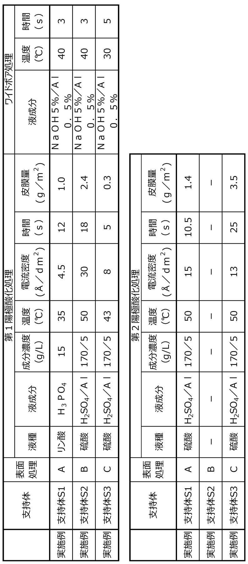
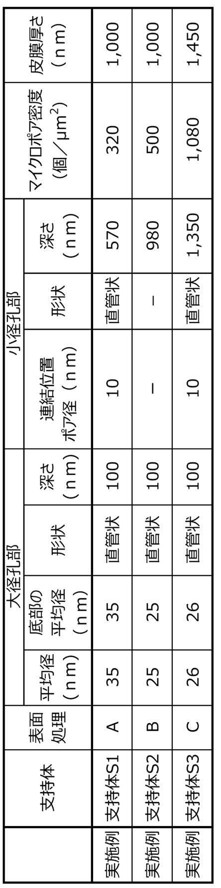
(実施例1~実施例67及び比較例1~4)
<平版印刷版原版の作製>
表3~表7に記載の支持体上に、下記組成の下塗り液(1)を乾燥塗布量が20mg/m2になるよう塗布し、100℃30秒間オーブンで乾燥し、下塗り層を有する支持体を作製した。
下塗り層上に、下記画像記録層塗布液(1)をバー塗布し、100℃で60秒間オーブン乾燥して乾燥塗布量0.60g/m2(膜厚=約0.60μm)の画像記録層を形成し、平版印刷版原版を得た。
更にその後、必要に応じて、画像記録層上に、下記組成のオーバーコート層塗布液(1)を塗布し、100℃で60秒間オーブン乾燥して乾燥塗布量1.0g/m2(膜厚=約1.0μm)のオーバーコート層(疎水部を含む)を形成し、平版印刷版原版を得た。
<平版印刷版原版の作製>
表3~表7に記載の支持体上に、下記組成の下塗り液(1)を乾燥塗布量が20mg/m2になるよう塗布し、100℃30秒間オーブンで乾燥し、下塗り層を有する支持体を作製した。
下塗り層上に、下記画像記録層塗布液(1)をバー塗布し、100℃で60秒間オーブン乾燥して乾燥塗布量0.60g/m2(膜厚=約0.60μm)の画像記録層を形成し、平版印刷版原版を得た。
更にその後、必要に応じて、画像記録層上に、下記組成のオーバーコート層塗布液(1)を塗布し、100℃で60秒間オーブン乾燥して乾燥塗布量1.0g/m2(膜厚=約1.0μm)のオーバーコート層(疎水部を含む)を形成し、平版印刷版原版を得た。
〔下塗り液(1)〕
・下記の下塗り化合物1:0.18部
・メタノール:55.24部
・蒸留水:6.15部
・下記の下塗り化合物1:0.18部
・メタノール:55.24部
・蒸留水:6.15部
-下塗り化合物1の合成-
<<モノマーM-1の精製>>
ライトエステル P-1M(2-メタクリロイルオキシエチルアシッドホスフェート、共栄社化学(株)製)420部、ジエチレングリコールジブチルエーテル1,050部及び蒸留水1,050部を分液ロートに加え、激しく撹拌した後静置した。上層を廃棄した後、ジエチレングリコールジブチルエーテル1,050部を加え、激しく撹拌した後静置した。上層を廃棄してモノマーM-1の水溶液(固形分換算10.5質量%)を1,300部得た。
<<モノマーM-1の精製>>
ライトエステル P-1M(2-メタクリロイルオキシエチルアシッドホスフェート、共栄社化学(株)製)420部、ジエチレングリコールジブチルエーテル1,050部及び蒸留水1,050部を分液ロートに加え、激しく撹拌した後静置した。上層を廃棄した後、ジエチレングリコールジブチルエーテル1,050部を加え、激しく撹拌した後静置した。上層を廃棄してモノマーM-1の水溶液(固形分換算10.5質量%)を1,300部得た。
<<下塗り化合物1の合成>>
三口フラスコに、蒸留水を53.73部、以下に示すモノマーM-2を3.66部加え、窒素雰囲気下で55℃に昇温した。次に、以下に示す滴下液1を2時間掛けて滴下し、30分撹拌した後、VA-046B(富士フイルム和光純薬(株)製)0.386部を加え、80℃に昇温し、1.5時間撹拌した。反応液を室温(25℃)に戻した後、30質量%水酸化ナトリウム水溶液を加え、pHを8.0に調整したのち、4-ヒドロキシ-2,2,6,6-テトラメチルピペリジン-1-オキシル(4-OH-TEMPO)を0.005部加えた。以上の操作により、下塗り化合物1の水溶液を180部得た。ゲル浸透クロマトグラフィー(GPC)法によるポリエチレングリコール換算値とした重量平均分子量(Mw)は17万であった。
三口フラスコに、蒸留水を53.73部、以下に示すモノマーM-2を3.66部加え、窒素雰囲気下で55℃に昇温した。次に、以下に示す滴下液1を2時間掛けて滴下し、30分撹拌した後、VA-046B(富士フイルム和光純薬(株)製)0.386部を加え、80℃に昇温し、1.5時間撹拌した。反応液を室温(25℃)に戻した後、30質量%水酸化ナトリウム水溶液を加え、pHを8.0に調整したのち、4-ヒドロキシ-2,2,6,6-テトラメチルピペリジン-1-オキシル(4-OH-TEMPO)を0.005部加えた。以上の操作により、下塗り化合物1の水溶液を180部得た。ゲル浸透クロマトグラフィー(GPC)法によるポリエチレングリコール換算値とした重量平均分子量(Mw)は17万であった。

<<滴下液1>>
・上記モノマーM-1水溶液:87.59部
・上記モノマーM-2:14.63部
・VA-046B(2,2’-アゾビス[2-(2-イミダゾリン-2-イル)プロパン]ジスルフェートジハイドレート、富士フイルム和光純薬(株)製):0.386部
・蒸留水:20.95部
・上記モノマーM-1水溶液:87.59部
・上記モノマーM-2:14.63部
・VA-046B(2,2’-アゾビス[2-(2-イミダゾリン-2-イル)プロパン]ジスルフェートジハイドレート、富士フイルム和光純薬(株)製):0.386部
・蒸留水:20.95部
<画像記録層塗布液(1)>
・表3~表7に記載の赤外線吸収剤(下記構造の化合物):表3~表7に記載の量
・表3~表7に記載の重合性化合物(下記構造の化合物):表3~表7に記載の量
・表3~表7に記載の熱可塑性樹脂1~6:表3~表7に記載の量
・BYK306(Byk Chemie社):0.008部
・1-メトキシ-2-プロパノール:8.609部
・メチルエチルケトン:1.091部
・表3~表7に記載の電子受容型重合開始剤:表3~表7に記載の量
・表3~表7に記載の電子供与型重合開始剤:表3~表7に記載の量、「なし」と記載の場合は0部
・表3~表7に記載の現像促進剤:表3~表7に記載の量
・表3~表7に記載の感脂化剤:表3~表7に記載の量
・表3~表7に記載の酸発色剤:表3~表7に記載の量
・表3~表7に記載の赤外線吸収剤(下記構造の化合物):表3~表7に記載の量
・表3~表7に記載の重合性化合物(下記構造の化合物):表3~表7に記載の量
・表3~表7に記載の熱可塑性樹脂1~6:表3~表7に記載の量
・BYK306(Byk Chemie社):0.008部
・1-メトキシ-2-プロパノール:8.609部
・メチルエチルケトン:1.091部
・表3~表7に記載の電子受容型重合開始剤:表3~表7に記載の量
・表3~表7に記載の電子供与型重合開始剤:表3~表7に記載の量、「なし」と記載の場合は0部
・表3~表7に記載の現像促進剤:表3~表7に記載の量
・表3~表7に記載の感脂化剤:表3~表7に記載の量
・表3~表7に記載の酸発色剤:表3~表7に記載の量
<オーバーコート層(OC層)塗布液>
・ポバールPVA105((株)クラレ製、けん化度80%以上):0.6質量部
・PEG4000(東京化成工業(株)製):0.39質量部
・界面活性剤(ラピゾールA-80、日油(株)製):0.01質量部
・水:全体が10質量部となる量
・ポバールPVA105((株)クラレ製、けん化度80%以上):0.6質量部
・PEG4000(東京化成工業(株)製):0.39質量部
・界面活性剤(ラピゾールA-80、日油(株)製):0.01質量部
・水:全体が10質量部となる量
<評価>
〔UV耐刷性〕
得られた平版印刷版原版を赤外線半導体レーザー搭載の富士フイルム(株)製Luxel PLATESETTER T-6000IIIにて、外面ドラム回転数1,000rpm、レーザー出力70%、解像度2,400dpi(dot per inch、1 inch=2.54cm)の条件で露光した。露光画像にはベタ画像、20μmドットFMスクリーンの50%網点チャート及び非画像部を含むようにした。
得られた露光済み平版印刷原版を現像処理することなく、(株)小森コーポレーション製印刷機LITHRONE26の版胴に取り付けた。版胴に対して給水ローラーを5%減速させた上で、Ecolity-2(富士フイルム(株)製)/水道水=2/98(容量比)の湿し水とUVインキ(T&K UV OFS K-HS墨GE-M((株)T&K TOKA製))とを用い、LITHRONE26の標準自動印刷スタート方法で湿し水とインキとを供給して機上現像した後、毎時10,000枚の印刷速度で、特菱アート(三菱製紙(株)製、連量:76.5kg)紙に印刷を50,000枚行った。
印刷枚数の増加にともない、徐々に画像記録層が磨耗しインキ受容性が低下するため、印刷用紙におけるインキ濃度が低下した。印刷物におけるFMスクリーン3%網点の網点面積率をX-Rite(X-Rite社製)で計測した値が印刷100枚目の計測値よりも5%低下したときの印刷部数を刷了枚数としてUV耐刷性を評価した。
〔UV耐刷性〕
得られた平版印刷版原版を赤外線半導体レーザー搭載の富士フイルム(株)製Luxel PLATESETTER T-6000IIIにて、外面ドラム回転数1,000rpm、レーザー出力70%、解像度2,400dpi(dot per inch、1 inch=2.54cm)の条件で露光した。露光画像にはベタ画像、20μmドットFMスクリーンの50%網点チャート及び非画像部を含むようにした。
得られた露光済み平版印刷原版を現像処理することなく、(株)小森コーポレーション製印刷機LITHRONE26の版胴に取り付けた。版胴に対して給水ローラーを5%減速させた上で、Ecolity-2(富士フイルム(株)製)/水道水=2/98(容量比)の湿し水とUVインキ(T&K UV OFS K-HS墨GE-M((株)T&K TOKA製))とを用い、LITHRONE26の標準自動印刷スタート方法で湿し水とインキとを供給して機上現像した後、毎時10,000枚の印刷速度で、特菱アート(三菱製紙(株)製、連量:76.5kg)紙に印刷を50,000枚行った。
印刷枚数の増加にともない、徐々に画像記録層が磨耗しインキ受容性が低下するため、印刷用紙におけるインキ濃度が低下した。印刷物におけるFMスクリーン3%網点の網点面積率をX-Rite(X-Rite社製)で計測した値が印刷100枚目の計測値よりも5%低下したときの印刷部数を刷了枚数としてUV耐刷性を評価した。
〔耐薬品性〕
各実施例又は比較例の平版印刷版原版を、上記耐刷性の評価と同様にして露光及び印刷を行った。5,000枚印刷する毎に、クリーナー(富士フイルム(株)製、マルチクリーナー)で版面を拭く工程を加えた以外は、上記耐刷性の評価と同様にして、耐薬品性を評価した。
具体的には、上記耐刷性の評価における刷了枚数に対する、上記版面を拭く工程を加えた場合の刷了枚数の割合を指標値とし、下記評価基準により評価した。
上記指標値が大きいほど、クリーナーで版面を拭く工程を加えた場合であっても、耐刷性の変化が小さいといえ、耐薬品性に優れるものといえる。
各実施例又は比較例の平版印刷版原版を、上記耐刷性の評価と同様にして露光及び印刷を行った。5,000枚印刷する毎に、クリーナー(富士フイルム(株)製、マルチクリーナー)で版面を拭く工程を加えた以外は、上記耐刷性の評価と同様にして、耐薬品性を評価した。
具体的には、上記耐刷性の評価における刷了枚数に対する、上記版面を拭く工程を加えた場合の刷了枚数の割合を指標値とし、下記評価基準により評価した。
上記指標値が大きいほど、クリーナーで版面を拭く工程を加えた場合であっても、耐刷性の変化が小さいといえ、耐薬品性に優れるものといえる。
-評価基準-
5:指標値が95%以上100%以下である
4:指標値が80%以上95%未満である
3:指標値が60%以上80%未満である
2:指標値が40%以上60%未満である
1:指標値が40%未満である
5:指標値が95%以上100%以下である
4:指標値が80%以上95%未満である
3:指標値が60%以上80%未満である
2:指標値が40%以上60%未満である
1:指標値が40%未満である
〔経時での非画像部の機上現像性〕
経時サンプル(平版印刷版原版の経時品)は、下記方法で高温高湿下環境に放置することによって経時を加速させたサンプルとして作製した。
上記で得られた、露光前の平版印刷版原版を温度25℃、湿度70%の環境に1時間曝露させ、外気の出入りがないように梱包した後、温度50℃の環境で3日放置し、経時サンプルとした。
上記経時サンプルを赤外線半導体レーザー搭載の富士フイルム(株)製Luxel PLATESETTER T-6000IIIにて、外面ドラム回転数1,000rpm(revolutions per minute)、レーザー出力70%、解像度2,400dpi(dot per inch、1 inch=2.54cm)の条件で露光した。露光画像にはベタ画像及び20μmドットFMスクリーンの50%網点チャートを含むようにした。
得られた露光済みの平版印刷版原版を現像処理することなく、(株)小森コーポレーション製印刷機LITHRONE26の版胴に取り付けた。Ecolity-2(富士フイルム(株)製)/水道水=2/98(容量比)の湿し水とスペースカラーフュージョンG墨インキ(DICグラフィックス(株)製)とを用い、LITHRONE26の標準自動印刷スタート方法で湿し水とインキとを供給して機上現像した後、毎時10,000枚の印刷速度で、特菱アート(連量:76.5kg)紙に印刷を500枚行った。
画像記録層の未露光部の印刷機上での機上現像が完了し、非画像部にインキが転写しない状態になるまでに要した印刷用紙の枚数を機上現像性として計測し、以下の基準で評価した。枚数が少ないほど、機上現像性に優れるといえる。
経時サンプル(平版印刷版原版の経時品)は、下記方法で高温高湿下環境に放置することによって経時を加速させたサンプルとして作製した。
上記で得られた、露光前の平版印刷版原版を温度25℃、湿度70%の環境に1時間曝露させ、外気の出入りがないように梱包した後、温度50℃の環境で3日放置し、経時サンプルとした。
上記経時サンプルを赤外線半導体レーザー搭載の富士フイルム(株)製Luxel PLATESETTER T-6000IIIにて、外面ドラム回転数1,000rpm(revolutions per minute)、レーザー出力70%、解像度2,400dpi(dot per inch、1 inch=2.54cm)の条件で露光した。露光画像にはベタ画像及び20μmドットFMスクリーンの50%網点チャートを含むようにした。
得られた露光済みの平版印刷版原版を現像処理することなく、(株)小森コーポレーション製印刷機LITHRONE26の版胴に取り付けた。Ecolity-2(富士フイルム(株)製)/水道水=2/98(容量比)の湿し水とスペースカラーフュージョンG墨インキ(DICグラフィックス(株)製)とを用い、LITHRONE26の標準自動印刷スタート方法で湿し水とインキとを供給して機上現像した後、毎時10,000枚の印刷速度で、特菱アート(連量:76.5kg)紙に印刷を500枚行った。
画像記録層の未露光部の印刷機上での機上現像が完了し、非画像部にインキが転写しない状態になるまでに要した印刷用紙の枚数を機上現像性として計測し、以下の基準で評価した。枚数が少ないほど、機上現像性に優れるといえる。
-評価基準-
5:機上現像枚数が25枚以下である
4:機上現像枚数が26枚~30枚である
3:機上現像枚数が31枚~35枚である
2:機上現像枚数が36枚~40枚である
1:機上現像枚数が40枚を超える
5:機上現像枚数が25枚以下である
4:機上現像枚数が26枚~30枚である
3:機上現像枚数が31枚~35枚である
2:機上現像枚数が36枚~40枚である
1:機上現像枚数が40枚を超える
〔インキ着肉性(印刷初期インキ着肉性)〕
得られた平版印刷版原版を上記UV耐刷性の評価における露光と同様の露光条件により露光した(露光画像にはベタ画像及び20μmドットFMスクリーンの50%網点チャートを含むようにした。)平版印刷版を、(株)小森コーポレーション製印刷機LITHRONE26の版胴に取り付けた。Ecolity-2(富士フイルム(株)製)/水道水=2/98(容量比)の湿し水とValues-G(N)墨インキ(DIC(株)製)とを用い、LITHRONE26の標準自動印刷スタート方法で湿し水とインキとを供給して印刷を開始し、毎時10,000枚の印刷速度で、特菱アート(三菱製紙(株)製、連量:76.5kg)紙に印刷を100枚行った。
ベタ画像部におけるインキ濃度を、マクベス濃度計(X-Rite社製、exact)を用いて測定し、1.0以上となるまでに要した印刷用紙の枚数をインキ着肉性(印刷初期インキ着肉性)の指標値として下記評価基準に従い評価した。枚数が少ないほど、平版印刷版は着肉性に優れるといえる。
得られた平版印刷版原版を上記UV耐刷性の評価における露光と同様の露光条件により露光した(露光画像にはベタ画像及び20μmドットFMスクリーンの50%網点チャートを含むようにした。)平版印刷版を、(株)小森コーポレーション製印刷機LITHRONE26の版胴に取り付けた。Ecolity-2(富士フイルム(株)製)/水道水=2/98(容量比)の湿し水とValues-G(N)墨インキ(DIC(株)製)とを用い、LITHRONE26の標準自動印刷スタート方法で湿し水とインキとを供給して印刷を開始し、毎時10,000枚の印刷速度で、特菱アート(三菱製紙(株)製、連量:76.5kg)紙に印刷を100枚行った。
ベタ画像部におけるインキ濃度を、マクベス濃度計(X-Rite社製、exact)を用いて測定し、1.0以上となるまでに要した印刷用紙の枚数をインキ着肉性(印刷初期インキ着肉性)の指標値として下記評価基準に従い評価した。枚数が少ないほど、平版印刷版は着肉性に優れるといえる。
-評価基準-
1:指標値が100枚以上である
2:指標値が50枚以上100枚未満である
3:指標値が30枚以上50枚未満である
4:指標値が20枚以上30枚未満である
5:指標値が20枚未満である
1:指標値が100枚以上である
2:指標値が50枚以上100枚未満である
3:指標値が30枚以上50枚未満である
4:指標値が20枚以上30枚未満である
5:指標値が20枚未満である

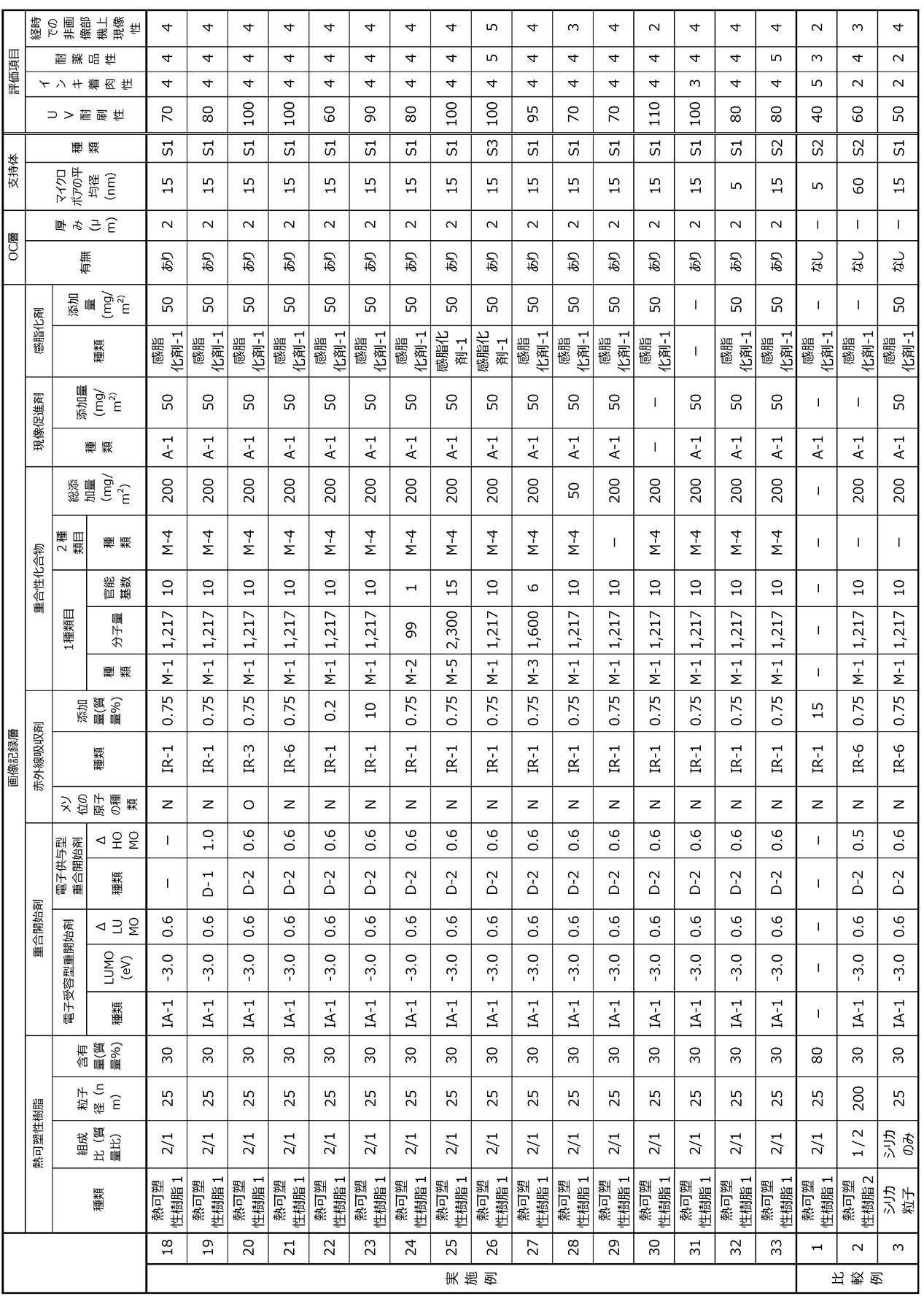
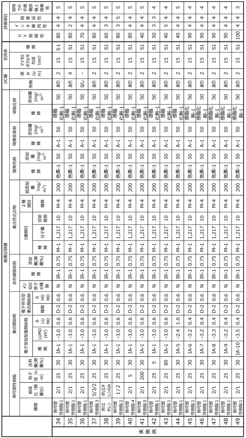
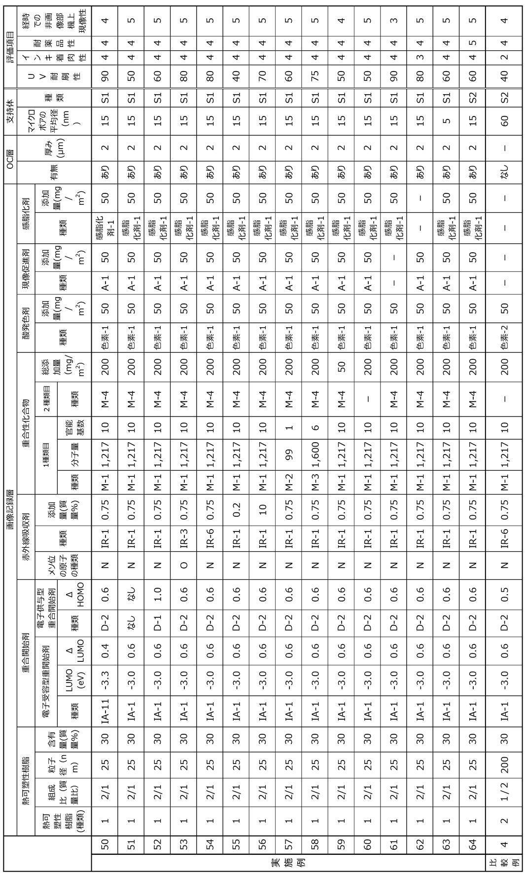
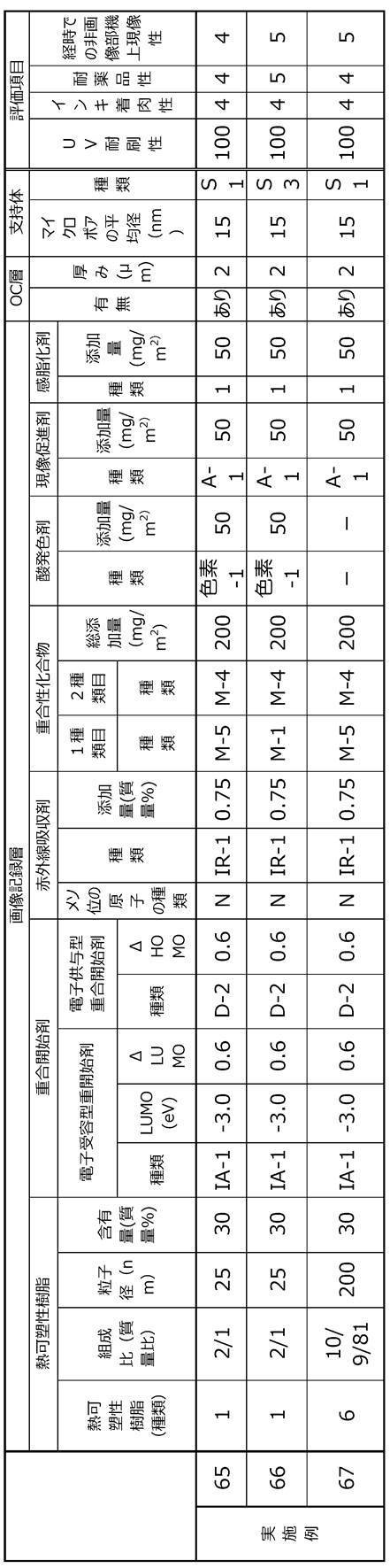
表3~表7中、熱可塑性樹脂の欄の「種類」の欄の記載は、下記熱可塑性樹脂1~熱可塑性樹脂6のいずれの化合物を使用したかを示している。
表3~表7中、熱可塑性樹脂の組成比の欄は、左から(芳香族ビニル化合物の構成単位の量比)/(シアノ基を有する構成単位)/(N-ビニル複素環化合物により形成される構成単位)の順で記載している。例えば、熱可塑性樹脂の組成比の欄「2/1」とは、(芳香族ビニル化合物の構成単位の量比)/(シアノ基を有する構成単位)が、質量比で2/1であることを示している。
表7中の実施例67の熱可塑性樹脂6の組成比の欄は、左から、PEGMA/スチレン/アクリロニトリルの順で記載している。
電子受容型重合開始剤の「種類」の欄の記載は、下記化合物IA-1、及び、IA-5~IA-11のいずれかを使用したかを示している。電子供与型重合開始剤の「種類」の欄の記載は、下記化合物D-1又は化合物D-2を使用したかを示している。
ΔLUMOとは、赤外線吸収剤のLUMOと上記電子受容型重合開始剤のLUMOとの差(赤外線吸収剤のLUMO-電子受容型重合開始剤のLUMOの値)を示している。ΔHOMOとは、電子供与型重合開始剤のHOMOと、上記赤外線吸収剤のHOMOとの差(電子供与型重合開始剤のHOMO-赤外線吸収剤のHOMOの値)を示している。
なお、LUMO及びHOMOの単位は、eVである。
表3~表7中、赤外線吸収剤の「種類」の欄の記載は、下記赤外線吸収剤IR-1、IR-3又はIR-6のいずれの化合物を使用したかを示している。赤外線吸収剤の「メソ位の原子の種類」の欄の記載において、Nは窒素原子を示し、Oは酸素原子を示す。
表3~表7中、「-」とは該当する成分を含まないことを意味している。
表3~表7中、重合性化合物を2種含む場合、1種類目の重合性化合物を20質量%、2種類目の重合性化合物を80質量%の含有量比で含んでいることを意味している。
表3~表7に記載の化合物の詳細は下記の通りである。
表3~表7中、熱可塑性樹脂の組成比の欄は、左から(芳香族ビニル化合物の構成単位の量比)/(シアノ基を有する構成単位)/(N-ビニル複素環化合物により形成される構成単位)の順で記載している。例えば、熱可塑性樹脂の組成比の欄「2/1」とは、(芳香族ビニル化合物の構成単位の量比)/(シアノ基を有する構成単位)が、質量比で2/1であることを示している。
表7中の実施例67の熱可塑性樹脂6の組成比の欄は、左から、PEGMA/スチレン/アクリロニトリルの順で記載している。
電子受容型重合開始剤の「種類」の欄の記載は、下記化合物IA-1、及び、IA-5~IA-11のいずれかを使用したかを示している。電子供与型重合開始剤の「種類」の欄の記載は、下記化合物D-1又は化合物D-2を使用したかを示している。
ΔLUMOとは、赤外線吸収剤のLUMOと上記電子受容型重合開始剤のLUMOとの差(赤外線吸収剤のLUMO-電子受容型重合開始剤のLUMOの値)を示している。ΔHOMOとは、電子供与型重合開始剤のHOMOと、上記赤外線吸収剤のHOMOとの差(電子供与型重合開始剤のHOMO-赤外線吸収剤のHOMOの値)を示している。
なお、LUMO及びHOMOの単位は、eVである。
表3~表7中、赤外線吸収剤の「種類」の欄の記載は、下記赤外線吸収剤IR-1、IR-3又はIR-6のいずれの化合物を使用したかを示している。赤外線吸収剤の「メソ位の原子の種類」の欄の記載において、Nは窒素原子を示し、Oは酸素原子を示す。
表3~表7中、「-」とは該当する成分を含まないことを意味している。
表3~表7中、重合性化合物を2種含む場合、1種類目の重合性化合物を20質量%、2種類目の重合性化合物を80質量%の含有量比で含んでいることを意味している。
表3~表7に記載の化合物の詳細は下記の通りである。
〔熱可塑性樹脂粒子の合成〕
-熱可塑性樹脂1の合成-
モノマーとしてスチレン及びアクリロニトリルを使用してシード乳化重合によりポリマーエマルジョン(熱可塑性樹脂)を調製した。下記の表面活性剤が、モノマーを加える前に反応槽中に存在することを確認した。2リットルの二重ジャケット反応槽に、10.35gのChemfac PB-133(Chemax社製、Chemfac PB-133、リン酸アルキルエーテル表面活性剤)、1.65gのNaHCO3及び1482.1gの脱塩水を加えた。上記反応槽に窒素を流し、75℃まで加熱した。反応槽の内容物の温度が75℃に達した時、1.5%のモノマー混合物を加えた(即ち、2.29gのスチレン及び1.16gのアクリロニトリルのモノマー混合物)。モノマー混合物を15分間、75℃で乳化し、続いて37.95gの2質量%過硫酸ナトリウム水溶液を加えた。続いて反応槽を80℃の温度に30分間加熱した。次いで残るモノマー混合物(150.1gのスチレン及び76.5gのアクリロニトリルのモノマー混合物)を、180分間にわたり反応混合物に投入した。モノマー混合物の添加と同時に、追加量の過硫酸ナトリウム水溶液を加えた(37.95gの2質量%Na2S2O8水溶液)。モノマー混合物の添加が完了した後、反応槽を60分間、80℃で加熱した。残存モノマーの量を減らすために、減圧蒸留を80℃で1時間行った。続いて反応槽を室温に冷却し、100ppmのProxel Ultra 5(Arch Biocides UK社製、1,2-ベンズイソチアゾール3(2H)-オンの5質量%水溶液)を殺菌剤として加え、そしてラテックス状態のポリマーを粗い濾紙を使用して濾過し、熱可塑性樹脂1を調製した。
-熱可塑性樹脂1の合成-
モノマーとしてスチレン及びアクリロニトリルを使用してシード乳化重合によりポリマーエマルジョン(熱可塑性樹脂)を調製した。下記の表面活性剤が、モノマーを加える前に反応槽中に存在することを確認した。2リットルの二重ジャケット反応槽に、10.35gのChemfac PB-133(Chemax社製、Chemfac PB-133、リン酸アルキルエーテル表面活性剤)、1.65gのNaHCO3及び1482.1gの脱塩水を加えた。上記反応槽に窒素を流し、75℃まで加熱した。反応槽の内容物の温度が75℃に達した時、1.5%のモノマー混合物を加えた(即ち、2.29gのスチレン及び1.16gのアクリロニトリルのモノマー混合物)。モノマー混合物を15分間、75℃で乳化し、続いて37.95gの2質量%過硫酸ナトリウム水溶液を加えた。続いて反応槽を80℃の温度に30分間加熱した。次いで残るモノマー混合物(150.1gのスチレン及び76.5gのアクリロニトリルのモノマー混合物)を、180分間にわたり反応混合物に投入した。モノマー混合物の添加と同時に、追加量の過硫酸ナトリウム水溶液を加えた(37.95gの2質量%Na2S2O8水溶液)。モノマー混合物の添加が完了した後、反応槽を60分間、80℃で加熱した。残存モノマーの量を減らすために、減圧蒸留を80℃で1時間行った。続いて反応槽を室温に冷却し、100ppmのProxel Ultra 5(Arch Biocides UK社製、1,2-ベンズイソチアゾール3(2H)-オンの5質量%水溶液)を殺菌剤として加え、そしてラテックス状態のポリマーを粗い濾紙を使用して濾過し、熱可塑性樹脂1を調製した。
熱可塑性樹脂1は、スチレンにより形成される構成単位と、アクリロニトリルにより形成される構成単位との組成比は2:1(質量比)であり、固形分量は、20質量%であり、平均粒子径は25nmであり、ガラス転移温度は120℃であった。
-熱可塑性樹脂2、4及び5の合成-
使用するモノマー及びその使用量を適宜変更した以外は、上記熱可塑性樹脂1と同様の方法により合成を行った。
使用するモノマー及びその使用量を適宜変更した以外は、上記熱可塑性樹脂1と同様の方法により合成を行った。
-熱可塑性樹脂3の合成-
三口フラスコに、メチルエチルケトン300gを入れ、窒素気流下、80℃に加熱した。この反応容器に、スチレン:50.0g、アクリロニトリル:30.0g、N-ビニルピロリドン:20.0g、AIBN:0.7g、メチルエチルケトン100gからなる混合溶液を30分かけて滴下した。滴下終了後、更に7.5時間反応を続けた。その後、AIBN 0.3gを加え、更に12時間反応を続けた。反応終了後、室温まで反応液を冷却した。スチレンにより形成される構成単位と、アクリロニトリルにより形成される構成単位と、N-ビニルピロリドンにより形成される構成単位の組成比は50:30:20(質量比)であり、熱可塑性樹脂3の重量平均分子量は75,000であった。また、固形分量は、20質量%であった。
三口フラスコに、メチルエチルケトン300gを入れ、窒素気流下、80℃に加熱した。この反応容器に、スチレン:50.0g、アクリロニトリル:30.0g、N-ビニルピロリドン:20.0g、AIBN:0.7g、メチルエチルケトン100gからなる混合溶液を30分かけて滴下した。滴下終了後、更に7.5時間反応を続けた。その後、AIBN 0.3gを加え、更に12時間反応を続けた。反応終了後、室温まで反応液を冷却した。スチレンにより形成される構成単位と、アクリロニトリルにより形成される構成単位と、N-ビニルピロリドンにより形成される構成単位の組成比は50:30:20(質量比)であり、熱可塑性樹脂3の重量平均分子量は75,000であった。また、固形分量は、20質量%であった。
-ポリエチレン-
Polybead Polystyrene Microspheres(2.5% Solids-Latex)、0.20μm(Polyscience社製)、粒子径;200nm
Polybead Polystyrene Microspheres(2.5% Solids-Latex)、0.20μm(Polyscience社製)、粒子径;200nm
-シリカ粒子-
スノーテックMP-1040(日産化学(株)製)、粒子径70nm~130nm
スノーテックMP-1040(日産化学(株)製)、粒子径70nm~130nm
-熱可塑性樹脂6(親水性基を有する熱可塑性樹脂)の合成-
50.5部の脱イオン水と242.2部のn-プロパノールとの混合物中に溶解された20部のポリエチレングリコールメチルエーテルメタクリレート(PEGMA)の溶液を、四つ首フラスコ内に装入し、そしてN2雰囲気下でわずかに還流するまで(~73℃)ゆっくりと加熱した。スチレン(9部)、アクリロニトリル(81部)、及び、VAZO-64(2,2’-アゾビス(イソブチロニトリル)、0.7部)の予備混合物を、2時間にわたって添加した。6時間後、VAZO-64を更に0.5部添加した。温度を80℃まで上昇させた。続いて、VAZO-64 0.7部を12時間にわたって添加した。全部で20時間にわたる反応後、グラフトコポリマーへの変換率は、不揮発分パーセントの測定に基づいて、>98%であった。PEGMA/スチレン/アクリロニトリルの質量比は、10:9:81であり、そしてn-プロパノール/水の比は、80:20であった。熱可塑性樹脂6の数平均粒子径は200nmであった。
ここで、数平均粒子径は、熱可塑性樹脂6の電子顕微鏡写真を撮影し、写真上で粒子の円相当径を総計で5,000個測定し、その平均の値である。円相当径とは、粒子の写真上における投影面積と同じ面積の円の直径を意味する。
50.5部の脱イオン水と242.2部のn-プロパノールとの混合物中に溶解された20部のポリエチレングリコールメチルエーテルメタクリレート(PEGMA)の溶液を、四つ首フラスコ内に装入し、そしてN2雰囲気下でわずかに還流するまで(~73℃)ゆっくりと加熱した。スチレン(9部)、アクリロニトリル(81部)、及び、VAZO-64(2,2’-アゾビス(イソブチロニトリル)、0.7部)の予備混合物を、2時間にわたって添加した。6時間後、VAZO-64を更に0.5部添加した。温度を80℃まで上昇させた。続いて、VAZO-64 0.7部を12時間にわたって添加した。全部で20時間にわたる反応後、グラフトコポリマーへの変換率は、不揮発分パーセントの測定に基づいて、>98%であった。PEGMA/スチレン/アクリロニトリルの質量比は、10:9:81であり、そしてn-プロパノール/水の比は、80:20であった。熱可塑性樹脂6の数平均粒子径は200nmであった。
ここで、数平均粒子径は、熱可塑性樹脂6の電子顕微鏡写真を撮影し、写真上で粒子の円相当径を総計で5,000個測定し、その平均の値である。円相当径とは、粒子の写真上における投影面積と同じ面積の円の直径を意味する。
〔重合性化合物〕
M-1:ジペンタエリスリトールペンタアクリレートヘキサメチレンジイソシアネート ウレタンプレポリマー、UA-510H 共栄社化学(株)製、官能基数;10、Mw;1,217
M-2:ジメチルアクリルアミド、官能基数;1、Mw;99
M-3;ポリエステルアクリレート、EBECRYL450 ダイセル・オルネクス(株)製、官能基数;6 Mw;1,600
M-1:ジペンタエリスリトールペンタアクリレートヘキサメチレンジイソシアネート ウレタンプレポリマー、UA-510H 共栄社化学(株)製、官能基数;10、Mw;1,217
M-2:ジメチルアクリルアミド、官能基数;1、Mw;99
M-3;ポリエステルアクリレート、EBECRYL450 ダイセル・オルネクス(株)製、官能基数;6 Mw;1,600
M-4:下記構造の化合物(ジペンタエリスリトールヘキサアクリレート、DPHA(新中村化学工業(株)製、官能基数;6、Mw;578)
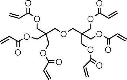
M-5:下記構造の化合物、U-15HA(新中村化学工業(株)製)、官能基数;15、Mw;2,300

〔電子供与型重合開始剤〕
D-1:下記構造の化合物 HOMO(eV)=-6.329
D-2:下記構造の化合物 HOMO(eV)=-6.052
D-1:下記構造の化合物 HOMO(eV)=-6.329
D-2:下記構造の化合物 HOMO(eV)=-6.052

〔電子受容型重合開始剤〕
IA-1:下記構造の化合物
IA-5~IA-11:下記構造の化合物
IA-1:下記構造の化合物
IA-5~IA-11:下記構造の化合物
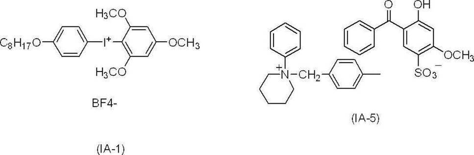
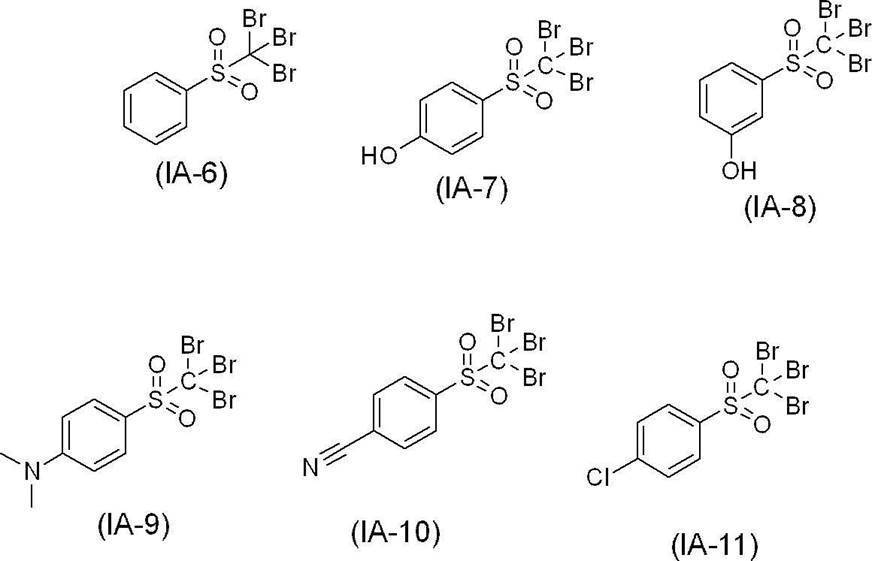
〔赤外線吸収剤〕
IR-1:下記構造の化合物
IR-3:下記構造の化合物
IR-6:下記構造の化合物、非分解性赤外線吸収剤
IR-1:下記構造の化合物
IR-3:下記構造の化合物
IR-6:下記構造の化合物、非分解性赤外線吸収剤
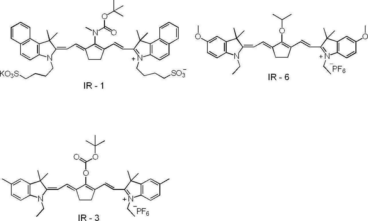
〔現像促進剤〕
A-1:トリス(2-ヒドロキシエチル)イソシアヌレート、SP値の極性項の値=6.4
A-1:トリス(2-ヒドロキシエチル)イソシアヌレート、SP値の極性項の値=6.4
〔感脂化剤〕
感脂化剤-1:1,4-ビス(トリフェニルホスホニオ)ブタン=ジ(ヘキサフルオロホスファート、SP値=16.2
感脂化剤-1:1,4-ビス(トリフェニルホスホニオ)ブタン=ジ(ヘキサフルオロホスファート、SP値=16.2
〔酸発色剤〕
色素-1:下記化合物
色素-2:下記化合物
色素-1:下記化合物
色素-2:下記化合物
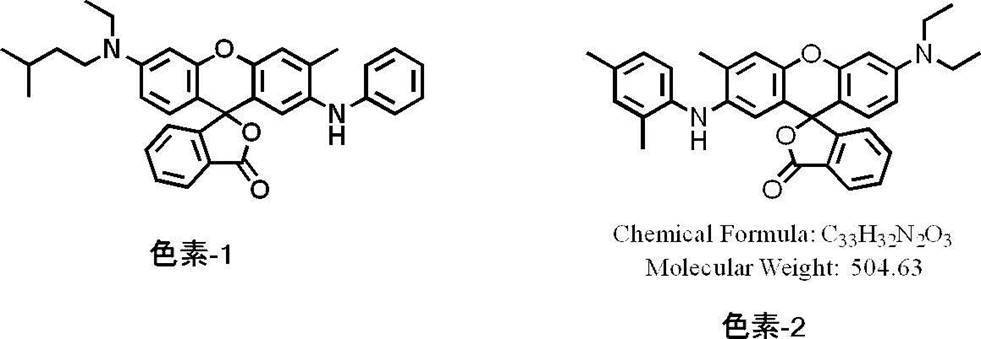
表3~表7に記載した結果から、実施例に係る平版印刷版原版は、比較例に係る平版印刷版原版と比べて、UV耐刷性に優れた平版印刷版が得られることがわかる。また、本開示に係る平版印刷版原版は、耐薬品性、インキ着肉性及び経時での非画像部の機上現像性にも優れた平版印刷版が得られることがわかる。
2018年11月30日に出願された日本国特許出願第2018-225964号の開示、及び、2019年6月28日に出願された日本国特許出願第2019-122488号の開示は、その全体が参照により本明細書に取り込まれる。
本明細書に記載された全ての文献、特許出願、及び、技術規格は、個々の文献、特許出願、及び、技術規格が参照により取り込まれることが具体的かつ個々に記された場合と同程度に、本明細書中に参照により取り込まれる。
本明細書に記載された全ての文献、特許出願、及び、技術規格は、個々の文献、特許出願、及び、技術規格が参照により取り込まれることが具体的かつ個々に記された場合と同程度に、本明細書中に参照により取り込まれる。
10:平版印刷版原版、12:アルミニウム支持体、16:画像記録層、14:下塗り層、18:アルミニウム板、20:陽極酸化皮膜、24:大径孔部、26:小径孔部、31:アルミニウム板、32a、32b及び32c:アルミニウムの陽極酸化皮膜、33a、33b及び33c:マイクロポア、50:主電解槽、52:ラジアルドラムローラ、51:交流電源、53a及び53b:主極、55:電解液、54:電解液供給口、56:スリット、57:電解液通路、60:補助陽極槽、58:補助陽極、Ex:電解液排出口、S:給液、W:アルミニウム板、1:アルミニウム板、2及び4:ローラ状ブラシ、3:研磨スラリー液、5、6、7及び8:支持ローラ、610:陽極酸化処理装置、612:給電槽、614:電解処理槽、616:アルミニウム板、618:電解液、620:給電電極、622:ローラ、624:ニップローラー、626:電解液、628:ローラ、630:電解電極、632:仕切り、634:直流電源、A:深さ、W:アルミニウム板、X1及びX3:陽極酸化皮膜の厚さ、X2及びX4:マイクロポア22の深さ、Y1及びY3:陽極酸化皮膜表面におけるマイクロポア22の平均径、Y2及びY4:マイクロポア22の底部の平均径、ta:アノード反応時間、tc:カソード反応時間、tp:電流が0からピークに達するまでの時間、Ia:アノードサイクル側のピーク時の電流、Ic:カソードサイクル側のピーク時の電流、AA:アルミニウム板のアノード反応の電流、CA:アルミニウム板のカソード反応の電流
Claims (29)
- 支持体上に画像記録層を有し、
前記画像記録層が、赤外線吸収剤、重合開始剤、重合性化合物、及び、熱可塑性樹脂粒子を含む、
平版印刷版原版。 - 前記熱可塑性樹脂粒子に含まれる熱可塑性樹脂のガラス転移温度が、60℃~150℃である、請求項1に記載の平版印刷版原版。
- 前記熱可塑性樹脂粒子に含まれる熱可塑性樹脂が、芳香族ビニル化合物より形成される構成単位、及び、シアノ基を有する構成単位を有する樹脂Aを含み、
前記樹脂Aにおける前記芳香族ビニル化合物より形成される構成単位の含有量が、前記シアノ基を有する構成単位の含有量より多い、請求項1又は請求項2に記載の平版印刷版原版。 - 前記熱可塑性樹脂粒子に含まれる熱可塑性樹脂が、親水性基を有する、請求項1~請求項3のいずれか1項に記載の平版印刷版原版。
- 前記熱可塑性樹脂粒子に含まれる熱可塑性樹脂が、前記親水性基として、ポリアルキレンオキシド構造を有する請求項4に記載の平版印刷版原版。
- 前記熱可塑性樹脂粒子の算術平均粒子径が、1nm以上80nm未満である、請求項1~請求項5のいずれか1項に記載の平版印刷版原版。
- 前記画像記録層の全質量に対する前記熱可塑性樹脂粒子の含有量が、10質量%以上50質量%以下である、請求項1~請求項6のいずれか1項に記載の平版印刷版原版。
- 前記重合開始剤が、電子受容型重合開始剤を含む、請求項1~請求項7のいずれか1項に記載の平版印刷版原版。
- 前記電子受容型重合開始剤のLUMOが、-3.0eV以下である、請求項8に記載の平版印刷版原版。
- 前記電子受容型重合開始剤のLUMOと前記赤外線吸収剤のLUMOとの差が、0.70eV以下である、請求項7又は請求項8に記載の平版印刷版原版。
- 前記重合開始剤が、電子供与型重合開始剤を更に含む、請求項1~請求項10のいずれか1項に記載の平版印刷版原版。
- 前記赤外線吸収剤のHOMOと前記電子供与型重合開始剤のHOMOとの差が、0.70eV以下である、請求項11に記載の平版印刷版原版。
- 前記赤外線吸収剤が、メソ位に酸素原子又は窒素原子を有するカチオン性のポリメチン色素である、請求項1~請求項12のいずれか1項に記載の平版印刷版原版。
- 前記赤外線吸収剤が、赤外線露光に起因する熱、及び、電子移動により分解する分解性赤外線吸収剤である、請求項1~請求項13のいずれか1項に記載の平版印刷版原版。
- 前記分解性赤外線吸収剤が、下記式1-1で表わされる赤外線吸収剤である、請求項14に記載の平版印刷版原版。
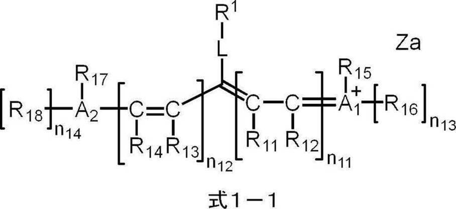
式1-1中、R1は下記式2で表される基を表し、R11~R18はそれぞれ独立に、水素原子、ハロゲン原子、-Ra、-ORb、-SRc又は-NRdReを表し、Ra~Reはそれぞれ独立に、炭化水素基を表し、A1、A2及び複数のR11~R18が連結して単環又は多環を形成してもよく、A1及びA2はそれぞれ独立に、酸素原子、硫黄原子又は窒素原子を表し、n11及びn12はそれぞれ独立に、0~5の整数を表し、但し、n11及びn12の合計は2以上であり、n13及びn14はそれぞれ独立に、0又は1を表し、Lは酸素原子、硫黄原子又は-NR10-を表し、R10は水素原子、アルキル基又はアリール基を表し、Zaは電荷を中和する対イオンを表す。
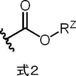
式2中、RZは、アルキル基を表し、波線は、前記式1-1中のLで表される基との結合部位を表す。 - 前記赤外線吸収剤の含有量が、前記画像記録層の全質量に対し、0.1質量%~10質量%である、請求項1~請求項15のいずれか1項に記載の平版印刷版原版。
- 前記重合性化合物のエチレン性不飽和結合当量が、200g/mol以下である、請求項1~請求項16のいずれか1項に記載の平版印刷版原版。
- 前記重合性化合物の重量平均分子量が、1,500以下である、請求項1~請求項17のいずれか1項に記載の平版印刷版原版。
- 前記重合性化合物が、3官能以上の重合性化合物を含む、請求項1~請求項18のいずれか1項に記載の平版印刷版原版。
- 前記重合性化合物が、7官能以上の重合性基を有する、請求項1~請求項18のいずれか1項に記載の平版印刷版原版。
- 前記重合性化合物が、10官能以上の重合性基を有する、請求項1~請求項18のいずれか1項に記載の平版印刷版原版。
- 前記画像記録層が、2種以上の重合性化合物を含む、請求項1~請求項21のいずれか1項に記載の平版印刷版原版。
- 前記画像記録層が、さらに酸発色剤を含む、請求項1~請求項22のいずれか1項に記載の平版印刷版原版。
- 前記画像記録層が、現像促進剤を更に含む、請求項1~請求項23のいずれか1項に記載の平版印刷版原版。
- 前記画像記録層が、感脂化剤を更に含む、請求項1~請求項24のいずれか1項に記載の平版印刷版原版。
- 前記支持体が画像記録層側の表面にマイクロポアを有し、
前記表面におけるマイクロポアの平均径が13nmを超え100nm以下である、請求項1~請求項25いずれか1項に記載の平版印刷版原版。 - 前記支持体が画像記録層側の表面に陽極酸化被膜を有し、
前記陽極酸化皮膜が、前記画像記録層側の陽極酸化皮膜表面から深さ方向にのびる前記マイクロポアを有し、
前記マイクロポアが、前記陽極酸化皮膜表面から深さ10nm~1,000nmの位置までのびる大径孔部と、
前記大径孔部の底部と連通し、前記連通位置から深さ20nm~2,000nmの位置までのびる小径孔部と、から構成され、
前記大径孔部の平均径が、13nmを超え100nm以下であり、
前記小径孔部の平均径が、前記大径孔部の平均径の5%~80%である、請求項26に記載の平版印刷版原版。 - 請求項1~請求項26のいずれか1項に記載の平版印刷版原版を、画像様に露光する工程と、
印刷機上で印刷インキ及び湿し水よりなる群から選ばれた少なくとも一方を供給して非画像部の画像記録層を除去する工程と、を含む
平版印刷版の作製方法。 - 請求項1~請求項26のいずれか1項に記載の平版印刷版原版を画像様に露光する工程と、
印刷機上で印刷インキ及び湿し水よりなる群から選ばれた少なくとも一方を供給して非画像部の画像記録層を除去し平版印刷版を作製する工程と、
得られた平版印刷版により印刷する工程と、を含む、
平版印刷方法。
Applications Claiming Priority (4)
| Application Number | Priority Date | Filing Date | Title |
|---|---|---|---|
| JP2018-225964 | 2018-11-30 | ||
| JP2018225964 | 2018-11-30 | ||
| JP2019122488A JP2020093518A (ja) | 2018-11-30 | 2019-06-28 | 平版印刷版原版、平版印刷版の作製方法、及び、平版印刷方法 |
| JP2019-122488 | 2019-06-28 |
Publications (1)
| Publication Number | Publication Date |
|---|---|
| WO2020111259A1 true WO2020111259A1 (ja) | 2020-06-04 |
Family
ID=70852825
Family Applications (1)
| Application Number | Title | Priority Date | Filing Date |
|---|---|---|---|
| PCT/JP2019/046871 Ceased WO2020111259A1 (ja) | 2018-11-30 | 2019-11-29 | 平版印刷版原版、平版印刷版の作製方法、及び、平版印刷方法 |
Country Status (1)
| Country | Link |
|---|---|
| WO (1) | WO2020111259A1 (ja) |
Cited By (1)
| Publication number | Priority date | Publication date | Assignee | Title |
|---|---|---|---|---|
| WO2021256341A1 (ja) * | 2020-06-17 | 2021-12-23 | 富士フイルム株式会社 | 機上現像型平版印刷版原版、平版印刷版の作製方法、及び、平版印刷方法 |
Citations (4)
| Publication number | Priority date | Publication date | Assignee | Title |
|---|---|---|---|---|
| US20090269699A1 (en) * | 2008-04-29 | 2009-10-29 | Munnelly Heidi M | On-press developable elements and methods of use |
| WO2018092661A1 (ja) * | 2016-11-16 | 2018-05-24 | 富士フイルム株式会社 | 輻射線感光性組成物、平版印刷版原版、及び、平版印刷版の製版方法 |
| WO2018159710A1 (ja) * | 2017-02-28 | 2018-09-07 | 富士フイルム株式会社 | 平版印刷版原版、平版印刷版の製版方法、及び、平版印刷方法 |
| JP2018140618A (ja) * | 2017-02-28 | 2018-09-13 | 富士フイルム株式会社 | 平版印刷版原版、平版印刷版の製造方法、印刷方法 |
-
2019
- 2019-11-29 WO PCT/JP2019/046871 patent/WO2020111259A1/ja not_active Ceased
Patent Citations (4)
| Publication number | Priority date | Publication date | Assignee | Title |
|---|---|---|---|---|
| US20090269699A1 (en) * | 2008-04-29 | 2009-10-29 | Munnelly Heidi M | On-press developable elements and methods of use |
| WO2018092661A1 (ja) * | 2016-11-16 | 2018-05-24 | 富士フイルム株式会社 | 輻射線感光性組成物、平版印刷版原版、及び、平版印刷版の製版方法 |
| WO2018159710A1 (ja) * | 2017-02-28 | 2018-09-07 | 富士フイルム株式会社 | 平版印刷版原版、平版印刷版の製版方法、及び、平版印刷方法 |
| JP2018140618A (ja) * | 2017-02-28 | 2018-09-13 | 富士フイルム株式会社 | 平版印刷版原版、平版印刷版の製造方法、印刷方法 |
Cited By (5)
| Publication number | Priority date | Publication date | Assignee | Title |
|---|---|---|---|---|
| WO2021256341A1 (ja) * | 2020-06-17 | 2021-12-23 | 富士フイルム株式会社 | 機上現像型平版印刷版原版、平版印刷版の作製方法、及び、平版印刷方法 |
| JPWO2021256341A1 (ja) * | 2020-06-17 | 2021-12-23 | ||
| CN115996852A (zh) * | 2020-06-17 | 2023-04-21 | 富士胶片株式会社 | 机上显影型平版印刷版原版、平版印刷版的制作方法及平版印刷方法 |
| JP7467629B2 (ja) | 2020-06-17 | 2024-04-15 | 富士フイルム株式会社 | 機上現像型平版印刷版原版、平版印刷版の作製方法、及び、平版印刷方法 |
| CN115996852B (zh) * | 2020-06-17 | 2026-03-20 | 富士胶片株式会社 | 机上显影型平版印刷版原版、平版印刷版的制作方法及平版印刷方法 |
Similar Documents
| Publication | Publication Date | Title |
|---|---|---|
| JP7096435B2 (ja) | 機上現像型平版印刷版原版、平版印刷版の作製方法、及び、平版印刷方法 | |
| JP7282886B2 (ja) | 機上現像型平版印刷版原版、平版印刷版の作製方法、及び、平版印刷方法 | |
| CN112930266B (zh) | 平版印刷版原版、平版印刷版的制作方法及平版印刷方法 | |
| EP3875281B1 (en) | Planographic printing plate precursor, method of preparing a planographic printing plate and planographic printing method | |
| WO2020090995A1 (ja) | 平版印刷版原版、平版印刷版の作製方法、及び、平版印刷方法 | |
| JP7397164B2 (ja) | 平版印刷版原版、平版印刷版の作製方法、及び、平版印刷方法 | |
| WO2020090996A1 (ja) | 平版印刷版原版、平版印刷版の作製方法、及び、平版印刷方法 | |
| JP2020093518A (ja) | 平版印刷版原版、平版印刷版の作製方法、及び、平版印刷方法 | |
| JP7378566B2 (ja) | 機上現像型平版印刷版原版、平版印刷版の作製方法、及び、平版印刷方法 | |
| JP7351862B2 (ja) | 平版印刷版原版、平版印刷版の作製方法、及び、平版印刷方法 | |
| WO2020111259A1 (ja) | 平版印刷版原版、平版印刷版の作製方法、及び、平版印刷方法 | |
| JP7184931B2 (ja) | 平版印刷版原版、平版印刷版の作製方法、及び、平版印刷方法 | |
| JP2020179567A (ja) | 平版印刷版原版、平版印刷版の作製方法、及び、平版印刷方法 | |
| CN112512827B (zh) | 机上显影型平版印刷版原版、平版印刷版的制作方法及平版印刷方法 | |
| CN112512828B (zh) | 机上显影型平版印刷版原版、平版印刷版的制作方法及平版印刷方法 | |
| CN112512823B (zh) | 机上显影型平版印刷版原版用粒子、平版印刷版原版 | |
| JP2021133666A (ja) | 機上現像型平版印刷版原版、平版印刷版の作製方法、及び、平版印刷方法 | |
| WO2020262690A1 (ja) | 機上現像型平版印刷版原版、平版印刷版の作製方法、及び、平版印刷方法 |
Legal Events
| Date | Code | Title | Description |
|---|---|---|---|
| 121 | Ep: the epo has been informed by wipo that ep was designated in this application |
Ref document number: 19890994 Country of ref document: EP Kind code of ref document: A1 |
|
| NENP | Non-entry into the national phase |
Ref country code: DE |
|
| 122 | Ep: pct application non-entry in european phase |
Ref document number: 19890994 Country of ref document: EP Kind code of ref document: A1 |