WO2020111204A1 - 血流障害判定装置、血流障害判定方法、血流障害判定プログラム及び血流障害判定システム - Google Patents
血流障害判定装置、血流障害判定方法、血流障害判定プログラム及び血流障害判定システム Download PDFInfo
- Publication number
- WO2020111204A1 WO2020111204A1 PCT/JP2019/046672 JP2019046672W WO2020111204A1 WO 2020111204 A1 WO2020111204 A1 WO 2020111204A1 JP 2019046672 W JP2019046672 W JP 2019046672W WO 2020111204 A1 WO2020111204 A1 WO 2020111204A1
- Authority
- WO
- WIPO (PCT)
- Prior art keywords
- blood flow
- pulse wave
- flow disorder
- wave data
- model
- Prior art date
- Legal status (The legal status is an assumption and is not a legal conclusion. Google has not performed a legal analysis and makes no representation as to the accuracy of the status listed.)
- Ceased
Links
Images





Classifications
-
- A—HUMAN NECESSITIES
- A61—MEDICAL OR VETERINARY SCIENCE; HYGIENE
- A61B—DIAGNOSIS; SURGERY; IDENTIFICATION
- A61B5/00—Measuring for diagnostic purposes; Identification of persons
- A61B5/02—Detecting, measuring or recording for evaluating the cardiovascular system, e.g. pulse, heart rate, blood pressure or blood flow
- A61B5/026—Measuring blood flow
Definitions
- the present invention relates to a blood flow disorder determination device, a blood flow disorder determination method, a blood flow disorder determination program, and a blood flow disorder determination system.
- a refill method that determines by the time it takes for the color of the patient's living tissue to change color after being pressed and discolored, a method of determining by the color of the living tissue, and a bleeding condition when a needle is pierced into the living tissue.
- the possibility of blood flow disorder is determined by the method.
- Patent Document 1 discloses a sensor sheet in which a plurality of types of sensing means for measuring blood flow information of different living tissues are arranged on a flexible base material. A blood flow disorder detection device having the above is described.
- a blood flow disorder can be detected based on the pulse wave of the patient, the color of the skin, and the temperature of the skin measured by the wearable sensor.
- the present invention provides a blood flow disorder determination device, a blood flow disorder determination method, a blood flow disorder determination program, and a blood flow disorder determination system that can more appropriately capture the characteristics of pulse wave data and determine a blood flow disorder. provide.
- the blood flow disorder determination device uses an acquisition unit that acquires pulse wave data obtained by measuring a time change of a pulse wave of a living body, and a first model that extracts periodic characteristics of the pulse wave data.
- a first generating unit that generates a first characteristic amount
- a second generating unit that generates a second characteristic amount by a second model that extracts a local characteristic of the pulse wave data, a first characteristic amount, and a second characteristic
- a determination unit that determines whether or not a blood flow disorder has occurred in the living body based on the amount.
- the first model may include a plurality of neural networks that generate a plurality of feature quantities for different cycles.
- the first model may include a plurality of groups of a plurality of neural networks.
- the characteristics of the pulse wave data can be captured by the ensemble of multiple neural networks, and the characteristics can be extracted with higher generalization performance.
- each of the plurality of neural networks may include a neuron that performs a convolution operation of pulse wave data at a predetermined cycle.
- the second model may include a convolutional neural network.
- the features included in the pulse wave data for a relatively short period of time can be captured, and the local feature amount can be generated.
- a blood flow disorder determination method by acquiring the pulse wave data measuring the time change of the pulse wave of the living body, by the first model to extract the periodic features of the pulse wave data, The first feature quantity is generated, the second feature quantity is generated by the second model that extracts the local feature of the pulse wave data, and the living body is generated based on the first feature quantity and the second feature quantity. Determining whether or not a blood flow disorder has occurred.
- a blood flow disorder determination program is a processor provided in a blood flow disorder determination device, an acquisition unit that acquires pulse wave data obtained by measuring a time change of a pulse wave of a living body, of the pulse wave data.
- a first generation unit that generates a first characteristic amount by a first model that extracts a periodic characteristic, and a second generation that generates a second characteristic amount by a second model that extracts a local characteristic of pulse wave data.
- a determination unit that determines whether or not a blood flow disorder has occurred in the living body based on the unit and the first and second characteristic amounts.
- a blood flow disorder determination system is a pulse wave sensor that measures a time change of a pulse wave of a living body and outputs pulse wave data, and a blood flow disorder occurs in the living body using the pulse wave data.
- a blood flow disorder determination system comprising: a blood flow disorder determination device for determining whether or not the blood flow disorder determination device includes: an acquisition unit that acquires pulse wave data; and a periodic feature of the pulse wave data.
- a first generation unit that generates a first feature amount by a first model that extracts a second feature amount, and a second generation unit that generates a second feature amount by a second model that extracts a local feature of the pulse wave data.
- a determination unit that determines whether or not a blood flow disorder has occurred in the living body based on the first characteristic amount and the second characteristic amount.
- a blood flow disorder determination device a blood flow disorder determination method, a blood flow disorder determination program, and a blood flow disorder determination system that can more appropriately capture the characteristics of pulse wave data to determine a blood flow disorder.
- a blood flow disorder determination device a blood flow disorder determination method, a blood flow disorder determination program, and a blood flow disorder determination system that can more appropriately capture the characteristics of pulse wave data to determine a blood flow disorder.
- FIG. 1 is a diagram showing an outline of a blood flow disorder determination system 100 according to an embodiment of the present invention.
- the blood flow disorder determination system 100 includes a blood flow disorder determination device 10, a sensor 20, and a transmitter 30.
- the blood flow disorder determination system 100 measures the time change of the pulse wave of the living body 1 by a flexible sensor 20 attached to the living body 1, and transmits the measured pulse wave data to a blood flow disorder determination device 10 via a transmitter 30. Then, the blood flow disorder determination device 10 determines whether or not a blood flow disorder has occurred in the living body 1.
- the blood flow disorder includes congestion and ischemia.
- the sensor 20 and the transmitter 30 are connected by wired communication, and the transmitter 30 and the blood flow disorder determination device 10 are connected by wireless communication.
- the communication method is arbitrary.
- the blood flow disorder determination device 10 is composed of a tablet computer.
- the blood flow disorder determination device 10 may be configured by a laptop computer or another type of computer.
- the blood flow disorder determination system 100 measures the time change of the color of the living body 1 with the sensor 20 or the time change of the temperature of the living body 1, and transmits the measured color data and temperature data to the transmitter 30. It may be transmitted to the blood flow disorder determination device 10 via the, and the blood flow disorder determination device 10 may determine whether or not a blood flow disorder has occurred in the living body 1.
- FIG. 2 is a diagram showing an outline of the sensor 20 included in the blood flow disorder determination system 100 according to the present embodiment.
- the sensor 20 includes a pulse wave sensor 21 that measures the time change of the pulse wave of the living body 1, a color sensor 22 that measures the time change of the color of the living body 1, and a temperature sensor 23 that measures the time change of the temperature of the living body 1.
- the numerical unit of the measure shown in FIG. 2 is cm.
- the sensor 20 according to the present embodiment is configured by mounting four pulse wave sensors 21, four color sensors 22, and four temperature sensors 23 on a flexible substrate 25. Further, the sensor 20 is configured such that one pulse wave sensor 21, one color sensor 22, and one temperature sensor 23 output blood flow data of one channel. The sensor 20 according to this embodiment outputs a total of four channels of blood flow data.
- the flexible substrate 25 is attached to the living body 1 so as to follow the deformation of the body surface.
- the pulse wave sensor 21 may be configured by, for example, an optical pulse wave sensor that irradiates the living body 1 with light and measures the pulse wave based on the amount of light absorbed.
- the color sensor 22 may include, for example, a photodiode that detects infrared light, a photodiode that detects red light, a photodiode that detects green light, and a photodiode that detects blue light.
- the temperature sensor 23 may be, for example, a thermistor.
- FIG. 3 is a diagram showing functional blocks of the blood flow disorder determination device 10 according to the present embodiment.
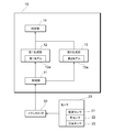
- the blood flow disorder determination device 10 includes an acquisition unit 11, a first generation unit 12, a second generation unit 13, and a determination unit 14.
- the acquisition unit 11 acquires a plurality of pulse wave data obtained by measuring the time change of the pulse wave of the living body 1 from the pulse wave sensor 21 via the transmitter 30.
- the acquisition unit 11 may acquire the color data obtained by measuring the time change of the color of the living body 1 from the color sensor 22 via the transmitter 30. Further, the acquisition unit 11 may acquire the temperature data obtained by measuring the time change of the temperature of the living body 1 from the temperature sensor 23 via the transmitter 30.
- the first generation unit 12 generates the first characteristic amount by the first model 12a that extracts the periodic characteristic of the pulse wave data.
- the first model 12a includes a plurality of neural networks that generate a plurality of feature quantities regarding different cycles. By generating a plurality of feature quantities related to a plurality of cycles, it is possible to capture the characteristics of various cycles included in the pulse wave data.
- Each of the plurality of neural networks includes a neuron that performs convolutional operation on pulse wave data at a predetermined cycle. This makes it possible to capture the characteristics of the pulse wave data regarding a predetermined cycle.
- the first model 12a includes a plurality of groups of a plurality of neural networks.
- the plurality of neural networks is a neural network that generates a plurality of feature quantities regarding different cycles.
- the characteristics of the pulse wave data can be captured by the ensemble of a plurality of neural networks, and the characteristics can be extracted with higher generalization performance.
- the second generation unit 13 generates the second characteristic amount by the second model 13a that extracts the local characteristic of the pulse wave data.
- the second model 13a includes a one-dimensional convolutional neural network. By using the convolutional neural network, the features included in the pulse wave data for a relatively short period of time can be captured, and the local feature amount can be generated.
- the determination unit 14 determines whether or not a blood flow disorder has occurred in the living body 1, based on the first characteristic amount and the second characteristic amount.
- the determination unit 14 inputs the feature amount obtained by combining the first feature amount and the second feature amount into the fully connected neural network and performs binary classification to determine whether the blood flow disorder has occurred in the living body 1. judge.
- the blood flow disorder determination device 10 by extracting the periodic feature and the local feature included in the pulse wave data, the feature of the pulse wave data is more appropriately captured and the blood flow disorder is detected. Can be determined.
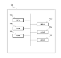
- FIG. 4 is a diagram showing a physical configuration of the blood flow disorder determination device 10 according to the present embodiment.
- the blood flow disorder determination device 10 communicates with a CPU (Central Processing Unit) 10a corresponding to a processor, a RAM (Random Access Memory) 10b corresponding to a storage unit, a ROM (Read Only Memory) 10c corresponding to a storage unit, and It has a section 10d, an input section 10e, and a display section 10f.
- a bus so that data can be transmitted and received.
- the blood flow disorder determination device 10 is composed of one computer will be described, but the blood flow disorder determination device 10 may be realized by combining a plurality of computers.
- the configuration shown in FIG. 4 is an example, and the blood flow disorder determination device 10 may have a configuration other than these, or may not have some of these configurations.
- the CPU 10a is a control unit that controls the execution of programs stored in the RAM 10b or the ROM 10c, calculates data, and processes the data.
- the CPU 10a is a calculation unit that executes a program (blood flow disorder determination program) that determines a blood flow disorder of the living body 1 based on pulse wave data.
- the CPU 10a receives various data from the input unit 10e and the communication unit 10d, displays the calculation result of the data on the display unit 10f, and stores it in the RAM 10b and the ROM 10c.
- the RAM 10b is a storage unit in which data can be rewritten, and may be composed of, for example, a semiconductor storage element.
- the RAM 10b may store a blood flow disorder determination program executed by the CPU 10a, pulse wave data, parameters of the first model 12a, parameters of the second model 13a, and the like. Note that these are merely examples, and data other than these may be stored in the RAM 10b, or some of these may not be stored.
- the ROM 10c is a storage unit capable of reading data, and may be composed of, for example, a semiconductor storage element.
- the ROM 10c may store, for example, a blood flow disorder determination program and data that is not rewritten.
- the communication unit 10d is an interface that connects the blood flow disorder determination device 10 to another device.
- the communication unit 10d may be connected to a communication network such as the Internet.
- the input unit 10e receives data input from the user, and may include, for example, a keyboard or a touch panel.
- the display unit 10f visually displays the calculation result by the CPU 10a, and may be configured by, for example, an LCD (Liquid Crystal Display).
- the display unit 10f may display pulse wave data or the risk of blood flow disorder.
- the blood flow disorder determination program may be provided by being stored in a computer-readable storage medium such as the RAM 10b or the ROM 10c, or may be provided via a communication network connected by the communication unit 10d.
- the CPU 10a executes the blood flow disorder determination program, so that the various operations described with reference to FIG. 3 are realized.
- the blood flow disorder determination device 10 may include an LSI (Large-Scale Integration) in which the CPU 10a and the RAM 10b and the ROM 10c are integrated.
- FIG. 5 is a figure which shows the outline of the 1st model 12a and the 2nd model 13a of the blood flow disorder determination apparatus 10 which concerns on this embodiment.
- the first model 12a receives the pulse wave data P of four channels each having a length L, and outputs N 2 -dimensional output data to the determination model 14a.
- the second model 13a receives the pulse wave data P of four channels each having a length L, and outputs K 3 -dimensional output data to the determination model 14a.
- the first model 12a includes a layer called "Periodic-Feature Extractor” and a fully coupled (FC) layer.
- the layer called "Periodic-Feature Extractor” inputs pulse wave data P of 4 channels each having a length L, outputs N 1 -dimensional data, and the fully connected layer inputs N 1 -dimensional data. , N 2 -dimensional data is output.
- the second model 13a includes three convolutional layers (Conv.) and a global average pooling (GAP) layer.
- the number of kernels is K 1
- the input data dimension is the dimension of the pulse wave data P
- the kernel size is P 1
- the number of kernels is K 2
- the input data dimension is K 1
- the kernel size is P 2
- the number of kernels is K 3
- the input data dimension is the dimension of the data output from the second convolutional layer
- the kernel size is P 3 .
- the GAP layer is a layer described in Lin, Min, Qiang Chen, and Shuicheng Yan, “Network in network,” arXiv:1312.4400, 2013. and outputs K 3 -dimensional data.
- the determination model 14a receives N 2 -dimensional data from the fully connected layer of the first model 12a, receives K 3 -dimensional data from the GAP layer of the second model 13a, and combines them (N 2 +K 3 ).
- the data is input to the fully connected layer as dimensional data, and N 3 dimensional data is output.
- N 3 2, and the output of the determination model 14a is (p, 1-p).
- p is the probability that a blood flow disorder has occurred in the living body 1.
- the first model 12a and the second model 13a can optimize the weight coefficient and the bias coefficient by supervised learning by the error back propagation method.
- the supervised learning is performed using pulse wave data P and label data indicating whether or not the pulse wave data P is for a case where a blood flow disorder has occurred.
- FIG. 6 is a diagram showing an outline of the first model 12a of the blood flow disorder determination device 10 according to the present embodiment.
- the first model 12a includes a plurality of blocks PB called periodic blocks.
- Each of the plurality of blocks PB receives the pulse wave data P having a length L as an input and outputs one-dimensional data.
- the number of blocks PB is B, and the data output from the plurality of blocks PB has a total of N 1 dimensions.
- the block PB is a group of a plurality of neural networks
- the first model 12a includes a plurality of groups of a plurality of neural networks.
- the plurality of neural networks included in the block PB will be described with reference to FIGS. 7 and 8.
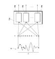
- FIG. 7 is a diagram showing an outline of the block PB that constitutes the first model 12a of the blood flow disorder determination device 10 according to the present embodiment.
- Each block PB includes a plurality of units PU called periodic units.
- the plurality of units PU have different values of the parameter T from each other, and the pulse wave data P having a length L is input to each of the units PU and outputs one-dimensional data.
- int( ⁇ ) is a function that truncates the decimal places and outputs an integer.
- the output of the block PB is a U-dimensional vector
- the u-th element is the output of the u-th unit PU.
- the B blocks PB each output a U-dimensional vector
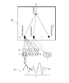
- FIG. 8 is a diagram showing an outline of the unit PU included in the block PB configuring the first model 12a of the blood flow obstruction determination device 10 according to the present embodiment.
- the unit PU receives the pulse wave data P having the length L as an input and outputs one-dimensional data. More specifically, the pulse wave data P represents the x, represents the weighting coefficient w, to represent a bias coefficient is b, the intermediate output u n is calculated by the following equation (1).
- v n Relu (u n )
- y max n (v n)
- Relu (u n) is a function that max (0, u n).
- the plurality of units PU have different parameters T and different output y values.
- the first model 12a inputs the outputs of the plurality of blocks PB to the fully connected layer and generates N 2 -dimensional feature quantities.
- FIG. 9 is a diagram showing a blood flow disorder determination result by the blood flow disorder determination device 10 according to the present embodiment.
- the horizontal axis indicates time (time), and the vertical axis indicates the risk (risk) of the blood flow disorder determined by the determination unit 14.
- the risk is calculated by a moving average for a predetermined period (for example, 30 minutes) of the probability that a blood flow disorder has occurred.
- the risk value sharply increased on the night of July 30, and is close to 1.0.
- a blood flow disorder was diagnosed by a doctor on the morning of July 31st.
- the blood flow disorder determination device 10 it is possible to continuously monitor the blood flow state of the patient and quickly detect the occurrence of the blood flow disorder.
- FIG. 10 is a diagram showing the blood flow disorder determination performance of the blood flow disorder determination device 10 according to the present embodiment.
- the case of the blood flow disorder determination device 10 according to the present embodiment and the case where the first model 12a of the present embodiment is replaced with an LSTM (Long Short-Term Memory) and the LSTM and the second model 13a are combined. Shows the sensitivity (Sensitivity), the specificity (Specificity), the accuracy (Accuracy), and the J value for the case where only the second model 13a is used and the case where only the first model 12a is used.
- LSTM Long Short-Term Memory
- the score of this embodiment is equal to or higher than the scores of other cases for any of sensitivity, specificity, accuracy and J value.
- the score of this embodiment is the best for the accuracy and the J value.
- the score is low when only the first model 12a is used and when only the second model 13a is used, and the blood flow disorder determination device 10 according to the present embodiment uses the pulse wave data by the first model 12a and the second model 13a. It can be read that the blood flow disorder can be determined with high accuracy by extracting the periodical feature and the local feature included in. Furthermore, the score of the blood flow disorder determination device 10 according to the present embodiment is higher than the score when the LSTM and the second model 13a are combined, and the first model 12a is more periodic than the LSTM and included in the pulse wave data. It can be seen that various features can be extracted appropriately.
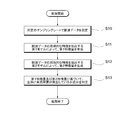
- FIG. 11 is a flowchart of blood flow disorder determination processing executed by the blood flow disorder determination system 100 according to the present embodiment.
- the blood flow disorder determination device 10 measures pulse wave data at a predetermined sampling rate (S10).
- the blood flow disorder determination device 10 After that, the blood flow disorder determination device 10 generates the first feature amount by the first model 12a that extracts the periodic feature of the pulse wave data (S11). Further, the blood flow disorder determination device 10 generates the second feature amount by the second model 13a that extracts the local feature of the pulse wave data (S12).
- the blood flow disorder determination device 10 determines whether or not a blood flow disorder has occurred in the living body based on the first characteristic amount and the second characteristic amount (S13).
- the blood flow disorder determination device 10 may output the moving average of the output values of the determination model 14a as a risk.
Landscapes
- Health & Medical Sciences (AREA)
- Life Sciences & Earth Sciences (AREA)
- Engineering & Computer Science (AREA)
- Medical Informatics (AREA)
- Physics & Mathematics (AREA)
- Cardiology (AREA)
- Biophysics (AREA)
- Pathology (AREA)
- Hematology (AREA)
- Biomedical Technology (AREA)
- Heart & Thoracic Surgery (AREA)
- Physiology (AREA)
- Molecular Biology (AREA)
- Surgery (AREA)
- Animal Behavior & Ethology (AREA)
- General Health & Medical Sciences (AREA)
- Public Health (AREA)
- Veterinary Medicine (AREA)
- Measuring Pulse, Heart Rate, Blood Pressure Or Blood Flow (AREA)
Abstract
脈波データの特徴をより適切に捉えて血流障害を判定することができる血流障害判定装置等を提供する。血流障害判定装置10は、生体1の脈波の時間変化を測定した脈波データを取得する取得部11と、脈波データの周期的な特徴を抽出する第1モデル12aによって、第1特徴量を生成する第1生成部12と、脈波データの局所的な特徴を抽出する第2モデル13aによって、第2特徴量を生成する第2生成部13と、第1特徴量及び第2特徴量に基づいて、生体に血流障害が発生しているか否かを判定する判定部14と、を備える。
Description
本発明は、血流障害判定装置、血流障害判定方法、血流障害判定プログラム及び血流障害判定システムに関する。
従来、医療現場では、鬱血や虚血といった血流障害が生じているか否かを医療スタッフが判断している。例えば、患者の生体組織を圧迫して変色させてから色が元に戻るまでの時間によって判断するレフィル法、生体組織の色によって判断する方法及び生体組織に針を刺した際の出血状態から判断する方法によって血流障害の可能性が判断されている。
血流障害の検出を自動化する技術として、下記特許文献1には、生体組織の異なる血流情報を計測する複数の種類の感知手段を、柔軟な基材上にそれぞれ複数配置してなるセンサーシートを有する血流障害検出装置が記載されている。
特許文献1に記載の技術によれば、ウェアラブルセンサによって測定した患者の脈波、皮膚の色及び皮膚の温度に基づいて血流障害を検出することができる。
しかしながら、従来は、脈波データに関してフーリエ変換やウェーブレット変換を行ってルールベースで特徴量を生成しており、脈波データの特徴を必ずしも適切に捉えられていない場合があった。
そこで、本発明は、脈波データの特徴をより適切に捉えて血流障害を判定することができる血流障害判定装置、血流障害判定方法、血流障害判定プログラム及び血流障害判定システムを提供する。
本発明の一態様に係る血流障害判定装置は、生体の脈波の時間変化を測定した脈波データを取得する取得部と、脈波データの周期的な特徴を抽出する第1モデルによって、第1特徴量を生成する第1生成部と、脈波データの局所的な特徴を抽出する第2モデルによって、第2特徴量を生成する第2生成部と、第1特徴量及び第2特徴量に基づいて、生体に血流障害が発生しているか否かを判定する判定部と、を備える。
この態様によれば、脈波データに含まれる周期的な特徴及び局所的な特徴を抽出することで、脈波データの特徴をより適切に捉えて血流障害を判定することができる。
上記態様において、第1モデルは、異なる周期に関する複数の特徴量を生成する複数のニューラルネットワークを含んでもよい。
この態様によれば、複数の周期に関する複数の特徴量を生成することで、脈波データに含まれる様々な周期の特徴を捉えることができる。
上記態様において、第1モデルは、複数のニューラルネットワークのまとまりを複数含んでもよい。
この態様によれば、複数のニューラルネットワークのアンサンブルによって脈波データの特徴を捉えることができ、より汎化性能の高い特徴抽出ができる。
上記態様において、複数のニューラルネットワークは、それぞれ、所定の周期で脈波データの畳み込み演算を行うニューロンを含んでもよい。
この態様によれば、所定の周期に関する脈波データの特徴を捉えることができる。
上記態様において、第2モデルは、畳み込みニューラルネットワークを含んでもよい。
この態様によれば、脈波データに含まれる比較的短期間の特徴を捉えることができ、局所的な特徴量を生成することができる。
本発明の他の態様に係る血流障害判定方法は、生体の脈波の時間変化を測定した脈波データを取得することと、脈波データの周期的な特徴を抽出する第1モデルによって、第1特徴量を生成することと、脈波データの局所的な特徴を抽出する第2モデルによって、第2特徴量を生成することと、第1特徴量及び第2特徴量に基づいて、生体に血流障害が発生しているか否かを判定することと、を含む。
この態様によれば、脈波データに含まれる周期的な特徴及び局所的な特徴を抽出することで、脈波データの特徴をより適切に捉えて血流障害を判定することができる。
本発明の他の態様に係る血流障害判定プログラムは、血流障害判定装置に備えられたプロセッサを、生体の脈波の時間変化を測定した脈波データを取得する取得部、脈波データの周期的な特徴を抽出する第1モデルによって、第1特徴量を生成する第1生成部、脈波データの局所的な特徴を抽出する第2モデルによって、第2特徴量を生成する第2生成部、及び第1特徴量及び第2特徴量に基づいて、生体に血流障害が発生しているか否かを判定する判定部、として機能させる。
この態様によれば、脈波データに含まれる周期的な特徴及び局所的な特徴を抽出することで、脈波データの特徴をより適切に捉えて血流障害を判定することができる。
本発明の他の態様に係る血流障害判定システムは、生体の脈波の時間変化を測定し、脈波データを出力する脈波センサと、脈波データを用いて生体に血流障害が発生しているか否かを判定する血流障害判定装置とを備える血流障害判定システムであって、血流障害判定装置は、脈波データを取得する取得部と、脈波データの周期的な特徴を抽出する第1モデルによって、第1特徴量を生成する第1生成部と、脈波データの局所的な特徴を抽出する第2モデルによって、第2特徴量を生成する第2生成部と、第1特徴量及び第2特徴量に基づいて、生体に血流障害が発生しているか否かを判定する判定部と、を有する。
この態様によれば、脈波データに含まれる周期的な特徴及び局所的な特徴を抽出することで、脈波データの特徴をより適切に捉えて血流障害を判定することができる。
本発明によれば、脈波データの特徴をより適切に捉えて血流障害を判定することができる血流障害判定装置、血流障害判定方法、血流障害判定プログラム及び血流障害判定システムを提供することができる。
添付図面を参照して、本発明の実施形態について説明する。なお、各図において、同一の符号を付したものは、同一又は同様の構成を有する。
図1は、本発明の実施形態に係る血流障害判定システム100の概要を示す図である。血流障害判定システム100は、血流障害判定装置10と、センサ20と、トランスミッタ30とを備える。
血流障害判定システム100は、生体1に貼付されるフレキシブルなセンサ20によって生体1の脈波の時間変化を測定し、測定した脈波データを、トランスミッタ30を介して血流障害判定装置10に送信し、血流障害判定装置10によって生体1に血流障害が生じているか否かを判定する。ここで、血流障害は、鬱血及び虚血を含む。本実施形態では、センサ20とトランスミッタ30は有線通信で接続され、トランスミッタ30と血流障害判定装置10は無線通信で接続されている。もっとも、通信方式は任意である。また、本実施形態では、血流障害判定装置10は、タブレットコンピュータで構成されている。もっとも、血流障害判定装置10は、ラップトップコンピュータで構成されてもよいし、他の形式のコンピュータで構成されてもよい。
また、血流障害判定システム100は、センサ20によって生体1の色の時間変化を測定したり、生体1の温度の時間変化を測定したりして、測定した色データ及び温度データを、トランスミッタ30を介して血流障害判定装置10に送信し、血流障害判定装置10によって生体1に血流障害が生じているか否かを判定してもよい。
図2は、本実施形態に係る血流障害判定システム100が備えるセンサ20の概要を示す図である。センサ20は、生体1の脈波の時間変化を測定する脈波センサ21と、生体1の色の時間変化を測定する色センサ22と、生体1の温度の時間変化を測定する温度センサ23と、を有する。なお、図2に示したメジャーの数値単位はcmである。
本実施形態に係るセンサ20は、フレキシブル基板25に4つの脈波センサ21と、4つの色センサ22と、4つの温度センサ23とが実装されて構成されている。また、センサ20は、1つの脈波センサ21と、1つの色センサ22と、1つの温度センサ23とで1チャンネルの血流データを出力するように構成されている。本実施形態に係るセンサ20は、合計4チャンネルの血流データを出力する。
フレキシブル基板25は、体表面の変形に追随するように生体1に貼付される。脈波センサ21は、例えば生体1に光を照射して、光の吸収量に基づき脈波を測定する光学式脈波センサで構成されてよい。色センサ22は、例えば、赤外線を検出するフォトダイオードと、赤色の光を検出するフォトダイオードと、緑色の光を検出するフォトダイオードと、青色の光を検出するフォトダイオードとによって構成されてよい。温度センサ23は、例えばサーミスタで構成されてよい。
図3は、本実施形態に係る血流障害判定装置10の機能ブロックを示す図である。血流障害判定装置10は、取得部11、第1生成部12、第2生成部13及び判定部14を備える。
取得部11は、生体1の脈波の時間変化を測定した複数の脈波データを、トランスミッタ30を介して脈波センサ21から取得する。なお、取得部11は、生体1の色の時間変化を測定した色データを、トランスミッタ30を介して色センサ22から取得してもよい。また、取得部11は、生体1の温度の時間変化を測定した温度データを、トランスミッタ30を介して温度センサ23から取得してもよい。
第1生成部12は、脈波データの周期的な特徴を抽出する第1モデル12aによって、第1特徴量を生成する。第1モデル12aは、異なる周期に関する複数の特徴量を生成する複数のニューラルネットワークを含む。複数の周期に関する複数の特徴量を生成することで、脈波データに含まれる様々な周期の特徴を捉えることができる。
複数のニューラルネットワークは、それぞれ、所定の周期で脈波データの畳み込み演算を行うニューロンを含む。これにより、所定の周期に関する脈波データの特徴を捉えることができる。
第1モデル12aは、複数のニューラルネットワークのまとまりを複数含む。ここで、複数のニューラルネットワークは、異なる周期に関する複数の特徴量を生成するニューラルネットワークである。このようにして、複数のニューラルネットワークのアンサンブルによって脈波データの特徴を捉えることができ、より汎化性能の高い特徴抽出ができる。
第2生成部13は、脈波データの局所的な特徴を抽出する第2モデル13aによって、第2特徴量を生成する。ここで、第2モデル13aは、1次元の畳み込みニューラルネットワークを含む。畳み込みニューラルネットワークを用いることで、脈波データに含まれる比較的短期間の特徴を捉えることができ、局所的な特徴量を生成することができる。
判定部14は、第1特徴量及び第2特徴量に基づいて、生体1に血流障害が発生しているか否かを判定する。判定部14は、第1特徴量及び第2特徴量を結合した特徴量を全結合ニューラルネットワークに入力し、2値分類を行うことで、生体1に血流障害が発生しているか否かを判定する。
本実施形態に係る血流障害判定装置10によれば、脈波データに含まれる周期的な特徴及び局所的な特徴を抽出することで、脈波データの特徴をより適切に捉えて血流障害を判定することができる。
図4は、本実施形態に係る血流障害判定装置10の物理的構成を示す図である。血流障害判定装置10は、プロセッサに相当するCPU(Central Processing Unit)10aと、記憶部に相当するRAM(Random Access Memory)10bと、記憶部に相当するROM(Read only Memory)10cと、通信部10dと、入力部10eと、表示部10fと、を有する。これらの各構成は、バスを介して相互にデータ送受信可能に接続される。なお、本例では血流障害判定装置10が一台のコンピュータで構成される場合について説明するが、血流障害判定装置10は、複数のコンピュータが組み合わされて実現されてもよい。また、図4で示す構成は一例であり、血流障害判定装置10はこれら以外の構成を有してもよいし、これらの構成のうち一部を有さなくてもよい。
CPU10aは、RAM10b又はROM10cに記憶されたプログラムの実行に関する制御やデータの演算、加工を行う制御部である。CPU10aは、脈波データに基づいて生体1の血流障害を判定するプログラム(血流障害判定プログラム)を実行する演算部である。CPU10aは、入力部10eや通信部10dから種々のデータを受け取り、データの演算結果を表示部10fに表示したり、RAM10bやROM10cに格納したりする。
RAM10bは、記憶部のうちデータの書き換えが可能なものであり、例えば半導体記憶素子で構成されてよい。RAM10bは、CPU10aが実行する血流障害判定プログラム、脈波データ、第1モデル12aのパラメータ及び第2モデル13aのパラメータ等を記憶してよい。なお、これらは例示であって、RAM10bには、これら以外のデータが記憶されていてもよいし、これらの一部が記憶されていなくてもよい。
ROM10cは、記憶部のうちデータの読み出しが可能なものであり、例えば半導体記憶素子で構成されてよい。ROM10cは、例えば血流障害判定プログラムや、書き換えが行われないデータを記憶してよい。
通信部10dは、血流障害判定装置10を他の機器に接続するインターフェースである。通信部10dは、インターネット等の通信ネットワークに接続されてよい。
入力部10eは、ユーザからデータの入力を受け付けるものであり、例えば、キーボードやタッチパネルを含んでよい。
表示部10fは、CPU10aによる演算結果を視覚的に表示するものであり、例えば、LCD(Liquid Crystal Display)により構成されてよい。表示部10fは、脈波データを表示したり、血流障害の危険度を表示したりしてよい。
血流障害判定プログラムは、RAM10bやROM10c等のコンピュータによって読み取り可能な記憶媒体に記憶されて提供されてもよいし、通信部10dにより接続される通信ネットワークを介して提供されてもよい。血流障害判定装置10では、CPU10aが血流障害判定プログラムを実行することにより、図3を用いて説明した様々な動作が実現される。なお、これらの物理的な構成は例示であって、必ずしも独立した構成でなくてもよい。例えば、血流障害判定装置10は、CPU10aとRAM10bやROM10cが一体化したLSI(Large-Scale Integration)を備えていてもよい。
図5は、本実施形態に係る血流障害判定装置10の第1モデル12a及び第2モデル13aの概要を示す図である。第1モデル12aは、それぞれ長さLである4チャンネルの脈波データPを入力として、N2次元の出力データを判定モデル14aに出力する。第2モデル13aは、それぞれ長さLである4チャンネルの脈波データPを入力として、K3次元の出力データを判定モデル14aに出力する。
第1モデル12aは、「Periodic-Feature Extractor」と呼ぶ層と、全結合(FC)層とを含む。「Periodic-Feature Extractor」と呼ぶ層は、それぞれ長さLである4チャンネルの脈波データPを入力として、N1次元のデータを出力し、全結合層は、N1次元のデータを入力として、N2次元のデータを出力する。
第2モデル13aは、3つの畳み込み層(Conv.)と、グローバルアベレージプーリング(GAP)層とを含む。第1畳み込み層は、カーネル数がK1であり、入力データ次元(脈波データPの次元)が1であり、カーネルのサイズがP1である。第2畳み込み層は、カーネル数がK2であり、入力データ次元(第1畳み込み層から出力されるデータの次元)がK1であり、カーネルのサイズがP2である。第3畳み込み層は、カーネル数がK3であり、入力データ次元(第2畳み込み層から出力されるデータの次元)がK2であり、カーネルのサイズがP3である。
GAP層は、Lin, Min, Qiang Chen, and Shuicheng Yan, "Network in network," arXiv:1312.4400, 2013.に記載された層であり、K3次元のデータを出力する。
判定モデル14aは、第1モデル12aの全結合層からN2次元のデータを受け付け、第2モデル13aのGAP層からK3次元のデータを受け付けて、それらを結合して(N2+K3)次元のデータとして、全結合層に入力し、N3次元のデータを出力する。ここで、N3=2であり、判定モデル14aの出力は(p,1-p)となる。ここで、pは、生体1に血流障害が発生している確率である。
第1モデル12a及び第2モデル13aは、誤差逆伝播法による教師あり学習で重み係数及びバイアス係数を最適化することができる。教師あり学習は、脈波データPと、その脈波データPが、血流障害が発生している場合のものであるか否かを示すラベルデータとを用いて行われる。
図6は、本実施形態に係る血流障害判定装置10の第1モデル12aの概要を示す図である。第1モデル12aは、periodic blockと呼ぶ複数のブロックPBを含む。複数のブロックPBは、それぞれ長さLの脈波データPを入力として、1次元のデータを出力する。ブロックPBの数はBであり、複数のブロックPBから出力されるデータは、合計でN1次元となる。
ブロックPBは、複数のニューラルネットワークのまとまりであり、第1モデル12aは、複数のニューラルネットワークのまとまりを複数含む。ブロックPBに含まれる複数のニューラルネットワークについては、図7及び8を用いて説明する。
図7は、本実施形態に係る血流障害判定装置10の第1モデル12aを構成するブロックPBの概要を示す図である。各ブロックPBは、periodic unitと呼ぶ複数のユニットPUを含む。複数のユニットPUは、互いにパラメータTの値が異なり、それぞれ長さLの脈波データPを入力として、1次元のデータを出力する。ここで、パラメータTは、T=TlからΔT刻みでT=Thまで設定される。具体的には、例えば、Tl=8、ΔT=1、Th=64として、56個のユニットPUを設定する。16Hzで脈波データPをサンプリングする場合、Tl=8は0.5秒に相当し、ΔT=1は1/16秒に相当し、Th=64は4秒に相当する。ブロックPBは、U=int((Th-Tl)/ΔT)+1個のユニットPUを含む。ここで、int(・)は、小数点以下を切り捨てて整数を出力する関数である。ブロックPBの出力は、U次元のベクトルであって、u番目の要素がu番目のユニットPUの出力である。B個のブロックPBは、それぞれU次元のベクトルを出力し、複数のブロックPBから出力されるデータは、合計でN1=B×U次元となる。
図8は、本実施形態に係る血流障害判定装置10の第1モデル12aを構成するブロックPBに含まれるユニットPUの概要を示す図である。ユニットPUは、長さLの脈波データPを入力として、1次元のデータを出力する。より具体的には、脈波データPをxと表し、重み係数をwと表し、バイアス係数をbと表すとき、以下の数式(1)により中間出力unが算出される。ここで、cは脈波データPのチャンネルを表し、c=1~4である。また、pはユニットPUが着目する周期を表し、p=1~Tである。また、lは、脈波データPを着目する周期で分割した場合の先頭データを指す数であり、l=0,T,2T…である。

ユニットPUは、vn=Relu(un)、y=maxn(vn)によって出力yを算出する。ここで、Relu(un)は、max(0,un)という関数である。
複数のユニットPUは、それぞれパラメータTが異なり、出力yの値が異なる。ブロックPBは、ユニットPUをU=int((Th-Tl)/ΔT)+1個含み、U個のユニットPUの出力yをまとめてU次元のベクトルとして出力する。さらに、第1モデル12aは、複数のブロックPBの出力を全結合層に入力し、N2次元の特徴量を生成する。
図9は、本実施形態に係る血流障害判定装置10による血流障害の判定結果を示す図である。同図では、横軸に時間(time)を示し、縦軸に判定部14により判定された血流障害が発生しているリスク(risk)を示している。ここで、リスクは、血流障害が発生している確率の所定期間(例えば30分間)に関する移動平均によって算出している。
同図によれば、7月30日の夜にリスクの値が急激に上昇し、1.0に近い値になっている。実際、この例について、7月31日の朝に、医師によって血流障害と診断された。このように、本実施形態に係る血流障害判定装置10によれば、患者の血流状態を連続的に監視して、血流障害の発生をいち早く検出することができる。
図10は、本実施形態に係る血流障害判定装置10による血流障害の判定性能を示す図である。同図では、本実施形態に係る血流障害判定装置10の場合と、本実施形態の第1モデル12aをLSTM(Long Short-Term Memory)に置き換えて、LSTMと第2モデル13aを組み合わせた場合と、第2モデル13aのみ用いた場合と、第1モデル12aのみ用いた場合とについて、それぞれ感度(Sensitivity)、特異度(Specificity)、正確度(Accuracy)及びJ値を示している。
True PositiveをTPと表し、False PositiveをFPと表し、True NegativeをTNと表し、False NegativeをFNと表すとき、感度は、TP/(TP+FN)で定義され、特異度は、TN/(FP+TN)で定義され、正確度は、(TP+TN)/(TP+FN+FP+TN)で定義され、J=Sensitivity+Specificity-1で定義される。
図10によると、感度、特異度、正確度及びJ値のいずれについても、本実施形態のスコアは、他の場合のスコア以上となっている。特に、正確度及びJ値について、本実施形態のスコアが最良となっている。
また、第1モデル12aのみの場合、第2モデル13aのみの場合は、スコアが低く、本実施形態に係る血流障害判定装置10は、第1モデル12a及び第2モデル13aによって、脈波データに含まれる周期的な特徴及び局所的な特徴を抽出することで、高い正確度で血流障害を判定できていることが読み取れる。さらに、本実施形態に係る血流障害判定装置10のスコアは、LSTMと第2モデル13aを組み合わせた場合のスコアよりも高く、第1モデル12aは、LSTMよりも脈波データに含まれる周期的な特徴を適切に抽出できていることが読み取れる。
図11は、本実施形態に係る血流障害判定システム100により実行される血流障害判定処理のフローチャートである。はじめに、血流障害判定装置10は、所定のサンプリングレートで脈波データを測定する(S10)。
その後、血流障害判定装置10は、脈波データの周期的な特徴を抽出する第1モデル12aによって、第1特徴量を生成する(S11)。また、血流障害判定装置10は、脈波データの局所的な特徴を抽出する第2モデル13aによって、第2特徴量を生成する(S12)。
最後に、血流障害判定装置10は、第1特徴量及び第2特徴量に基づいて、生体に血流障害が発生しているか否かを判定する(S13)。なお、血流障害判定装置10は、判定モデル14aの出力値の移動平均をリスクとして出力してもよい。
以上説明した実施形態は、本発明の理解を容易にするためのものであり、本発明を限定して解釈するためのものではない。実施形態が備える各要素並びにその配置、材料、条件、形状及びサイズ等は、例示したものに限定されるわけではなく適宜変更することができる。また、異なる実施形態で示した構成同士を部分的に置換し又は組み合わせることが可能である。
1…生体、10…血流障害判定装置、10a…CPU、10b…RAM、10c…ROM、10d…通信部、10e…入力部、10f…表示部、11…取得部、12…第1生成部、12a…第1モデル、13…第2生成部、13a…第2モデル、14…判定部、20…センサ、21…脈波センサ、22…色センサ、23…温度センサ、25…フレキシブル基板、30…トランスミッタ、100…血流障害判定システム
Claims (8)
- 生体の脈波の時間変化を測定した脈波データを取得する取得部と、
前記脈波データの周期的な特徴を抽出する第1モデルによって、第1特徴量を生成する第1生成部と、
前記脈波データの局所的な特徴を抽出する第2モデルによって、第2特徴量を生成する第2生成部と、
前記第1特徴量及び前記第2特徴量に基づいて、前記生体に血流障害が発生しているか否かを判定する判定部と、
を備える血流障害判定装置。 - 前記第1モデルは、異なる周期に関する複数の特徴量を生成する複数のニューラルネットワークを含む、
請求項1に記載の血流障害判定装置。 - 前記第1モデルは、前記複数のニューラルネットワークのまとまりを複数含む、
請求項2に記載の血流障害判定装置。 - 前記複数のニューラルネットワークは、それぞれ、所定の周期で前記脈波データの畳み込み演算を行うニューロンを含む、
請求項2又は3に記載の血流障害判定装置。 - 前記第2モデルは、畳み込みニューラルネットワークを含む、
請求項1から4のいずれか一項に記載の血流障害判定装置。 - 生体の脈波の時間変化を測定した脈波データを取得することと、
前記脈波データの周期的な特徴を抽出する第1モデルによって、第1特徴量を生成することと、
前記脈波データの局所的な特徴を抽出する第2モデルによって、第2特徴量を生成することと、
前記第1特徴量及び前記第2特徴量に基づいて、前記生体に血流障害が発生しているか否かを判定することと、
を含む血流障害判定方法。 - 血流障害判定装置に備えられたプロセッサを、
生体の脈波の時間変化を測定した脈波データを取得する取得部、
前記脈波データの周期的な特徴を抽出する第1モデルによって、第1特徴量を生成する第1生成部、
前記脈波データの局所的な特徴を抽出する第2モデルによって、第2特徴量を生成する第2生成部、及び
前記第1特徴量及び前記第2特徴量に基づいて、前記生体に血流障害が発生しているか否かを判定する判定部、
として機能させる血流障害判定プログラム。 - 生体の脈波の時間変化を測定し、脈波データを出力する脈波センサと、前記脈波データを用いて前記生体に血流障害が発生しているか否かを判定する血流障害判定装置とを備える血流障害判定システムであって、
前記血流障害判定装置は、
前記脈波データを取得する取得部と、
前記脈波データの周期的な特徴を抽出する第1モデルによって、第1特徴量を生成する第1生成部と、
前記脈波データの局所的な特徴を抽出する第2モデルによって、第2特徴量を生成する第2生成部と、
前記第1特徴量及び前記第2特徴量に基づいて、前記生体に血流障害が発生しているか否かを判定する判定部と、を有する、
血流障害判定システム。
Priority Applications (1)
| Application Number | Priority Date | Filing Date | Title |
|---|---|---|---|
| JP2020557840A JPWO2020111204A1 (ja) | 2018-11-30 | 2019-11-28 | 血流障害判定装置、血流障害判定方法、血流障害判定プログラム及び血流障害判定システム |
Applications Claiming Priority (2)
| Application Number | Priority Date | Filing Date | Title |
|---|---|---|---|
| US201862773240P | 2018-11-30 | 2018-11-30 | |
| US62/773,240 | 2018-11-30 |
Publications (1)
| Publication Number | Publication Date |
|---|---|
| WO2020111204A1 true WO2020111204A1 (ja) | 2020-06-04 |
Family
ID=70853457
Family Applications (1)
| Application Number | Title | Priority Date | Filing Date |
|---|---|---|---|
| PCT/JP2019/046672 Ceased WO2020111204A1 (ja) | 2018-11-30 | 2019-11-28 | 血流障害判定装置、血流障害判定方法、血流障害判定プログラム及び血流障害判定システム |
Country Status (2)
| Country | Link |
|---|---|
| JP (1) | JPWO2020111204A1 (ja) |
| WO (1) | WO2020111204A1 (ja) |
Citations (3)
| Publication number | Priority date | Publication date | Assignee | Title |
|---|---|---|---|---|
| US6572560B1 (en) * | 1999-09-29 | 2003-06-03 | Zargis Medical Corp. | Multi-modal cardiac diagnostic decision support system and method |
| US20130231947A1 (en) * | 2000-05-30 | 2013-09-05 | Vladimir Shusterman | Mobile System with Network-Distributed Data Processing for Biomedical Applications |
| US20160081608A1 (en) * | 2006-08-17 | 2016-03-24 | Jan Medical Inc. | Noninvasive Detection of Human Brain Conditions and Anomalies |
-
2019
- 2019-11-28 WO PCT/JP2019/046672 patent/WO2020111204A1/ja not_active Ceased
- 2019-11-28 JP JP2020557840A patent/JPWO2020111204A1/ja active Pending
Patent Citations (3)
| Publication number | Priority date | Publication date | Assignee | Title |
|---|---|---|---|---|
| US6572560B1 (en) * | 1999-09-29 | 2003-06-03 | Zargis Medical Corp. | Multi-modal cardiac diagnostic decision support system and method |
| US20130231947A1 (en) * | 2000-05-30 | 2013-09-05 | Vladimir Shusterman | Mobile System with Network-Distributed Data Processing for Biomedical Applications |
| US20160081608A1 (en) * | 2006-08-17 | 2016-03-24 | Jan Medical Inc. | Noninvasive Detection of Human Brain Conditions and Anomalies |
Also Published As
| Publication number | Publication date |
|---|---|
| JPWO2020111204A1 (ja) | 2021-10-21 |
Similar Documents
| Publication | Publication Date | Title |
|---|---|---|
| Shrivastava et al. | A new machine learning method for predicting systolic and diastolic blood pressure using clinical characteristics | |
| Egilmez et al. | UStress: Understanding college student subjective stress using wrist-based passive sensing | |
| Joung et al. | Continuous cuffless blood pressure monitoring using photoplethysmography-based PPG2BP-net for high intrasubject blood pressure variations | |
| WO2019060288A1 (en) | METHOD AND APPARATUS FOR DETERMINING A HEALTH CONDITION | |
| CN108113683A (zh) | 用于估计生物成分的装置和方法 | |
| JP6974975B2 (ja) | 肌指標値算出方法及び肌状態評価装置 | |
| AU2016201728B2 (en) | A system and method for determining psychological stress of a person | |
| Valero et al. | Development of a noninvasive blood glucose monitoring system prototype: Pilot study | |
| CN109549623A (zh) | 一种镜子和身体健康状态检测方法 | |
| CN110545735A (zh) | 信息处理方法、信息处理装置以及信息处理系统 | |
| Kim et al. | Internet of things and ensemble learning-based mental and physical fatigue monitoring for smart construction sites | |
| JP6547838B2 (ja) | 診断支援装置、診断支援方法、診断支援プログラム | |
| JP7557550B2 (ja) | 高血圧監視のためのシステムおよび方法 | |
| EP4698047A2 (en) | Deep learning-based photoplethysmography model for cardiovascular risk prediction | |
| Khan et al. | Classification of human physical activities and postures during everyday life | |
| KR20220150238A (ko) | 보행 속도에 기초한 노쇠 정도 측정기 | |
| CN115243606A (zh) | 用于监测外周糖尿病神经病变和/或外周动脉疾病的设备和方法 | |
| JPWO2020111204A1 (ja) | 血流障害判定装置、血流障害判定方法、血流障害判定プログラム及び血流障害判定システム | |
| Priya et al. | Characterization of wrist pulse using machine learning techniques | |
| Priyadarsini et al. | IoT based mobile app for continuous health monitoring of the person | |
| JP2015100525A (ja) | 診断データ生成装置および診断装置 | |
| Lago | Wearable Health Systems | |
| Puri et al. | Smart cervical band: an Internet of Things-and artificial intelligence-based neck pain and cervical spondylosis healing system | |
| Kadu et al. | Stress level diagnosis using IoT and machine learning | |
| JP2022178474A (ja) | 情報処理装置、情報処理方法、及び情報処理プログラム |
Legal Events
| Date | Code | Title | Description |
|---|---|---|---|
| 121 | Ep: the epo has been informed by wipo that ep was designated in this application |
Ref document number: 19890820 Country of ref document: EP Kind code of ref document: A1 |
|
| ENP | Entry into the national phase |
Ref document number: 2020557840 Country of ref document: JP Kind code of ref document: A |
|
| NENP | Non-entry into the national phase |
Ref country code: DE |
|
| 122 | Ep: pct application non-entry in european phase |
Ref document number: 19890820 Country of ref document: EP Kind code of ref document: A1 |