WO2020110506A1 - 表示装置および表示制御装置 - Google Patents
表示装置および表示制御装置 Download PDFInfo
- Publication number
- WO2020110506A1 WO2020110506A1 PCT/JP2019/041044 JP2019041044W WO2020110506A1 WO 2020110506 A1 WO2020110506 A1 WO 2020110506A1 JP 2019041044 W JP2019041044 W JP 2019041044W WO 2020110506 A1 WO2020110506 A1 WO 2020110506A1
- Authority
- WO
- WIPO (PCT)
- Prior art keywords
- display
- image
- display device
- object image
- coordinates
- Prior art date
- Legal status (The legal status is an assumption and is not a legal conclusion. Google has not performed a legal analysis and makes no representation as to the accuracy of the status listed.)
- Ceased
Links
Images






Classifications
-
- G—PHYSICS
- G06—COMPUTING OR CALCULATING; COUNTING
- G06F—ELECTRIC DIGITAL DATA PROCESSING
- G06F3/00—Input arrangements for transferring data to be processed into a form capable of being handled by the computer; Output arrangements for transferring data from processing unit to output unit, e.g. interface arrangements
- G06F3/14—Digital output to display device ; Cooperation and interconnection of the display device with other functional units
- G06F3/147—Digital output to display device ; Cooperation and interconnection of the display device with other functional units using display panels
-
- G—PHYSICS
- G09—EDUCATION; CRYPTOGRAPHY; DISPLAY; ADVERTISING; SEALS
- G09G—ARRANGEMENTS OR CIRCUITS FOR CONTROL OF INDICATING DEVICES USING STATIC MEANS TO PRESENT VARIABLE INFORMATION
- G09G3/00—Control arrangements or circuits, of interest only in connection with visual indicators other than cathode-ray tubes
- G09G3/20—Control arrangements or circuits, of interest only in connection with visual indicators other than cathode-ray tubes for presentation of an assembly of a number of characters, e.g. a page, by composing the assembly by combination of individual elements arranged in a matrix no fixed position being assigned to or needed to be assigned to the individual characters or partial characters
- G09G3/2092—Details of a display terminals using a flat panel, the details relating to the control arrangement of the display terminal and to the interfaces thereto
-
- G—PHYSICS
- G06—COMPUTING OR CALCULATING; COUNTING
- G06F—ELECTRIC DIGITAL DATA PROCESSING
- G06F3/00—Input arrangements for transferring data to be processed into a form capable of being handled by the computer; Output arrangements for transferring data from processing unit to output unit, e.g. interface arrangements
- G06F3/01—Input arrangements or combined input and output arrangements for interaction between user and computer
- G06F3/011—Arrangements for interaction with the human body, e.g. for user immersion in virtual reality
-
- G—PHYSICS
- G06—COMPUTING OR CALCULATING; COUNTING
- G06T—IMAGE DATA PROCESSING OR GENERATION, IN GENERAL
- G06T11/00—Two-dimensional [2D] image generation
- G06T11/60—Creating or editing images; Combining images with text
-
- G—PHYSICS
- G06—COMPUTING OR CALCULATING; COUNTING
- G06T—IMAGE DATA PROCESSING OR GENERATION, IN GENERAL
- G06T7/00—Image analysis
- G06T7/20—Analysis of motion
-
- G—PHYSICS
- G09—EDUCATION; CRYPTOGRAPHY; DISPLAY; ADVERTISING; SEALS
- G09G—ARRANGEMENTS OR CIRCUITS FOR CONTROL OF INDICATING DEVICES USING STATIC MEANS TO PRESENT VARIABLE INFORMATION
- G09G2320/00—Control of display operating conditions
- G09G2320/02—Improving the quality of display appearance
- G09G2320/0261—Improving the quality of display appearance in the context of movement of objects on the screen or movement of the observer relative to the screen
-
- G—PHYSICS
- G09—EDUCATION; CRYPTOGRAPHY; DISPLAY; ADVERTISING; SEALS
- G09G—ARRANGEMENTS OR CIRCUITS FOR CONTROL OF INDICATING DEVICES USING STATIC MEANS TO PRESENT VARIABLE INFORMATION
- G09G2340/00—Aspects of display data processing
- G09G2340/04—Changes in size, position or resolution of an image
-
- G—PHYSICS
- G09—EDUCATION; CRYPTOGRAPHY; DISPLAY; ADVERTISING; SEALS
- G09G—ARRANGEMENTS OR CIRCUITS FOR CONTROL OF INDICATING DEVICES USING STATIC MEANS TO PRESENT VARIABLE INFORMATION
- G09G2340/00—Aspects of display data processing
- G09G2340/04—Changes in size, position or resolution of an image
- G09G2340/0464—Positioning
-
- G—PHYSICS
- G09—EDUCATION; CRYPTOGRAPHY; DISPLAY; ADVERTISING; SEALS
- G09G—ARRANGEMENTS OR CIRCUITS FOR CONTROL OF INDICATING DEVICES USING STATIC MEANS TO PRESENT VARIABLE INFORMATION
- G09G2340/00—Aspects of display data processing
- G09G2340/04—Changes in size, position or resolution of an image
- G09G2340/0464—Positioning
- G09G2340/0478—Horizontal positioning
-
- G—PHYSICS
- G09—EDUCATION; CRYPTOGRAPHY; DISPLAY; ADVERTISING; SEALS
- G09G—ARRANGEMENTS OR CIRCUITS FOR CONTROL OF INDICATING DEVICES USING STATIC MEANS TO PRESENT VARIABLE INFORMATION
- G09G2340/00—Aspects of display data processing
- G09G2340/12—Overlay of images, i.e. displayed pixel being the result of switching between the corresponding input pixels
-
- G—PHYSICS
- G09—EDUCATION; CRYPTOGRAPHY; DISPLAY; ADVERTISING; SEALS
- G09G—ARRANGEMENTS OR CIRCUITS FOR CONTROL OF INDICATING DEVICES USING STATIC MEANS TO PRESENT VARIABLE INFORMATION
- G09G2340/00—Aspects of display data processing
- G09G2340/12—Overlay of images, i.e. displayed pixel being the result of switching between the corresponding input pixels
- G09G2340/125—Overlay of images, i.e. displayed pixel being the result of switching between the corresponding input pixels wherein one of the images is motion video
-
- G—PHYSICS
- G09—EDUCATION; CRYPTOGRAPHY; DISPLAY; ADVERTISING; SEALS
- G09G—ARRANGEMENTS OR CIRCUITS FOR CONTROL OF INDICATING DEVICES USING STATIC MEANS TO PRESENT VARIABLE INFORMATION
- G09G2340/00—Aspects of display data processing
- G09G2340/14—Solving problems related to the presentation of information to be displayed
-
- G—PHYSICS
- G09—EDUCATION; CRYPTOGRAPHY; DISPLAY; ADVERTISING; SEALS
- G09G—ARRANGEMENTS OR CIRCUITS FOR CONTROL OF INDICATING DEVICES USING STATIC MEANS TO PRESENT VARIABLE INFORMATION
- G09G2354/00—Aspects of interface with display user
Definitions
- the present disclosure relates to a display device that displays an image and a display control device used for such a display device.
- an image is displayed by being superimposed on an observation target such as an object or a person in the real space (for example, Patent Document 1).
- the display device includes a display unit and a display control unit.
- the display unit is capable of displaying an image on the observation target in an overlapping manner and is capable of displaying an object image.
- the display control unit is configured such that the horizontal display position of the object image in the display area of the display unit can be adjusted in pixel line units.
- the “display device” is not limited to a display device having only a display function, but also includes an electronic device having such a display device.
- a display control device is a display in which a horizontal display position of an object image displayed in a display area of a display unit capable of displaying an image on an observation target can be adjusted in pixel line units.
- a control unit is provided.
- the display unit is configured to be able to display an image on an observation target in an overlapping manner.
- the horizontal display position of the object image in the display area of the display unit is adjusted in pixel line units.
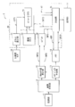
- FIG. 3 is a block diagram illustrating a configuration example of a display device according to an embodiment of the present disclosure. It is explanatory drawing showing an example of the image observed in the display area of the display apparatus shown in FIG. It is explanatory drawing showing an example of the relative positional relationship between an observation target and a display apparatus.
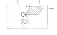
- FIG. 11 is an explanatory diagram illustrating another example of an image observed in the display area of the display device illustrated in FIG. 1.
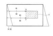
- FIG. 7 is an explanatory diagram illustrating an operation example of the display device illustrated in FIG. 1.
- FIG. 11 is another explanatory diagram illustrating an operation example of the display device illustrated in FIG. 1.
- FIG. 9 is an explanatory diagram illustrating another operation example of the display device illustrated in FIG. 1.
- FIG. 11 is an explanatory diagram illustrating another operation example of the display device illustrated in FIG. 1.
- FIG. 8 is another explanatory diagram illustrating another operation example of the display device illustrated in FIG. 1.
- FIG. 11 is an explanatory diagram illustrating another example of an image observed in the display area of the display device illustrated in FIG. 1. It is explanatory drawing showing an example of the image observed in the display area of the display apparatus which concerns on a comparative example. It is a block diagram showing an example of 1 composition of a display concerning a modification.
- FIG. 1 illustrates a configuration example of a display device (display device 1) according to an embodiment.
- the display device 1 is configured to be able to display an image on an observation target such as an object or a person in the real space, and is applied to, for example, smart glasses.
- the present invention is not limited to this, and may be applied to vehicles such as automobiles.
- a transmissive display device (so-called see-through display) may be attached to the windshield of the vehicle, or an image may be projected on the windshield of the vehicle.
- the display device 1 is configured to include a so-called see-through display in this example.
- the frame rate in the display device 1 is, for example, 60 Hz.
- the display device 1 displays an object image Pobj including information about the observation target near the observation target that actually exists on the other side of the see-through display in the display area D. That is, the observation target in the real space and the object image Pobj are superimposed on each other and observed by the user U of the display device 1.
- FIG. 2 shows an example of an image observed by the user U in the display area D of the display device 1.
- FIG. 2 includes a person A as an observation target and an object image Pobj.
- the person A is stationary on the other side of the display device 1, and the user U observes the person A in this real space via the display device 1.
- the display device 1 starts drawing a plurality of line images L included in the object image Pobj in order from the top at a position corresponding to the position of the person A (position B1).
- the object image Pobj is arranged such that the lower left point P is located near the face of the person A.
- the user U can directly observe the observation target in the real space and can grasp the information about the observation target.
- the display device 1 displays the display position of the object image Pobj according to the change of the position of the observation target. Are adjusted in pixel line units.
- FIG. 3 shows an example of a relative positional relationship between the user U and the display device 1 when the display device 1 moves.
- FIG. 4 shows an example of an image observed by the user U in the display area D of the display device 1.
- the user U of the display device 1 moves rightward with the display device 1 at the moving speed V.
- the moving speed V is a constant speed for convenience of description.
- the person A who is the observation target moves leftward at a constant speed.
- the display device 1 adjusts the display position of the object image Pobj in pixel line units according to the change in the position of the person A. Specifically, in this example, when the person A is at the position B1, the display device 1 starts drawing the plurality of line images L included in the object image Pobj in order from the top. Then, the display device 1 gradually shifts the drawing position of the line image L to the left according to the movement of the person A in the display area D from the position B1 to the position B2. As a result, the object image Pobj is deformed and displayed so that the lower left point P1 is located to the left of the upper left point O1. The lower left point P1 is located near the face of the person A. As a result, the display device 1 can reduce the possibility that the user will feel uncomfortable, as will be described later.
- the display device 1 includes an imaging unit 11, an image analysis unit 12, an object generation unit 13, a memory 14, a drawing position calculation unit 15, an acceleration sensor 16, a display control unit 20, and a display unit 17. ing.
- the image analysis unit 12, the object generation unit 13, the memory 14, the drawing position calculation unit 15, and the display control unit 20 are composed of, for example, a semiconductor circuit.
- the processing in the display device 1 may be realized by hardware or software.
- the image pickup unit 11 is configured to generate a picked-up image by picking up an object or a person in a real space, and includes, for example, a CMOS (complementary metal oxide semiconductor) image sensor.
- CMOS complementary metal oxide semiconductor
- the image analysis unit 12 performs an image analysis process based on the captured image generated by the image capturing unit 11 to identify the observation target included in the captured image, and generate information about the identified observation target. Composed.
- the image analysis unit 12 is configured to generate information about the specified observation target based on the data supplied from the server via the Internet, for example.
- the object generation unit 13 is configured to generate an object image Pobj including information about the specified observation target based on the processing result of the image analysis unit 12. Then, the object generation unit 13 supplies the generated object image Pobj to the memory 14 and also supplies information about the size of the object image Pobj (size information INFS) to the drawing position calculation unit 15.
- the memory 14 is configured to be able to store the object image Pobj generated by the object generator 13.
- the memory 14 includes, for example, a DRAM (Dynamic Random Access Memory) and an SRAM (Static Random Access Memory).
- the object image Pobj stored in the memory 14 is read based on an instruction from the display control unit 20.
- the drawing position calculation unit 15 coordinates the upper left point O of the object image Pobj in the display area D of the display unit 17 based on the processing result of the image analysis unit 12 and the size information INFS supplied from the object generation unit 13. Is configured to generate information (origin information INFO). Then, the drawing position calculation unit 15 is configured to supply the origin information INFO and the size information INFS to the display control unit 20.
- the acceleration sensor 16 is configured to detect the acceleration of the display device 1.
- the display control unit 20 is configured to read the object image Pobj from the memory 14 and supply the read object image Pobj to the display unit 17.
- the display control unit 20 includes an offset calculation unit 21, a coordinate counter 22, a calculation unit 23, a register 24, and a reading unit 25.
- the offset calculation unit 21 is configured to calculate the moving speed V of the display device 1 based on the detection result of the acceleration sensor 16 and the offset value OFS based on the moving speed V.
- the display device 1 is configured to shift the plurality of line images L in the display area D in the horizontal direction based on the offset value OFS.
- the coordinate counter 22 is configured to generate coordinates x and y in the display area D of the display unit 17. As shown in FIG. 2, the upper left coordinate in the display area D of the display unit 17 is (0, 0), the upper right coordinate is (X, 0), and the lower left coordinate is (0, Y). Yes, the lower right coordinates are (X,Y).
- the coordinate counter 22 generates the coordinates x and y in pixel line units from the upper left of the display area D of the display unit 17. Specifically, the coordinate counter 22 firstly (0,0), (1,0), (2,0),..., From the left in the uppermost pixel line in the display area D of the display unit 17. Coordinates x and y are generated as in (X,0). Next, the coordinate counter 22 determines the coordinates x and y in the next pixel line in order from the left, such as (0,1), (1,1), (2,1),..., (X,1). To generate. The same applies to the subsequent steps.
- the calculation unit 23 is configured to generate the coordinate x1 using the following formula, based on the offset value OFS generated by the offset calculation unit 21 and the coordinates x, y generated by the coordinate counter 22. ..
- the calculation unit 23 uses this equation EQ1 to integrate the offset value OFS over the range that the coordinate y can take to generate the coordinate x1.
- the calculation unit 23 generates the coordinate x1 by integrating the moving speed V over the range of the coordinate y.
- the coordinates x1, y are supplied to the reading unit 25.
- the register 24 is configured to store the origin information INFO and the size information INFS.
- the reading unit 25 reads the image information about the object image Pobj from the memory 14 based on the coordinates x1, y. Is composed of. Specifically, when the coordinates x1 and y are within the area S indicated by the origin information INFO and the size information INFS, the reading unit 25 generates the address ADR based on the coordinates x1 and y.
- the memory 14 supplies image information corresponding to the address ADR included in the stored object image Pobj to the reading unit 25 as data DATA.
- the reading unit 25 may specify the image information in pixel units, the image information in sub-pixel units, or the image information in a plurality of pixel units by using the address ADR. Good. Then, the reading unit 25 is configured to supply the read image information to the display unit 17 in the order of reading.
- the display unit 17 is a transmissive display device (so-called see-through display), and is configured to display the object image Pobj based on the image information about the object image Pobj read by the reading unit 25.
- the display unit 17 corresponds to a specific example of “display unit” in the present disclosure.
- the display control unit 20 corresponds to a specific but not limitative example of “display control unit” in one embodiment of the present disclosure.
- the acceleration sensor 16 corresponds to a specific but not limitative example of “acceleration sensor” in one embodiment of the present disclosure.
- the memory 14 corresponds to a specific but not limitative example of “first storage section” in one embodiment of the disclosure.
- the image pickup unit 11 generates a picked-up image by picking up an object or a person in the real space.
- the image analysis unit 12 specifies an observation target included in the captured image by performing an image analysis process based on the captured image generated by the imaging unit 11, and generates information about the specified observation target.
- the object generation unit 13 generates an object image Pobj including information about the identified observation target based on the processing result of the image analysis unit 12.
- the memory 14 stores the object image Pobj generated by the object generation unit 13.
- the drawing position calculation unit 15 coordinates the upper left point O of the object image Pobj in the display area D of the display unit 17 based on the processing result of the image analysis unit 12 and the size information INFS supplied from the object generation unit 13. Information (origin information INFO) is generated. Then, the drawing position calculation unit 15 supplies the origin information INFO and the size information INFS to the display control unit 20.
- the acceleration sensor 16 detects the acceleration of the display device 1.
- the offset calculation unit 21 of the display control unit 20 calculates the moving speed V of the display device 1 based on the detection result of the acceleration sensor 16, and calculates the offset value OFS based on the moving speed V.
- the coordinate counter 22 generates coordinates x, y in the display area D of the display unit 17.
- the calculation unit 23 generates the coordinate x1 based on the offset value OFS generated by the offset calculation unit 21 and the coordinates x, y generated by the coordinate counter 22.
- the register 24 is configured to store the origin information INFO and the size information INFS.
- the reading unit 25 reads the image information about the object image Pobj from the memory 14 based on the coordinates x1, y.
- the display unit 17 displays the object image Pobj based on the image information about the object image Pobj read by the reading unit 25.
- the offset value OFS is set to a negative value according to this constant speed.
- the calculation unit 23 uses the equation EQ1 to generate the coordinate x1 based on the coordinates x and y.
- the coordinate x1 is set to a value larger than the coordinate x.
- a region R1 is a coordinate region represented by coordinates x and y
- a region R2 is a coordinate region represented by coordinates x1 and y. That is, in this example, the larger the value of the coordinate y, the larger the coordinate x1 becomes than the coordinate x, and the region R2 shifts to the right.
- the reading unit 25 When the coordinates x1 and y are coordinates within the area S indicated by the origin information INFO and the size information INFS, the reading unit 25 generates an address ADR corresponding to the coordinates x1 and y and stores the address ADR from the memory 14. Image information corresponding to the address ADR is read. Specifically, for example, when the coordinates x1, y are the coordinates of the point O, the reading unit 25 reads the image information at the point O from the memory 14. In this way, the reading unit 25 sequentially reads the image information regarding the plurality of line images L included in the object image Pobj from the memory 14.
- the reading unit 25 reads the image information at the point O at an earlier timing.
- the horizontal distance W4 from the left end in the region R2 to the lower left point P of the region S is shorter than the horizontal distance W3 from the left end in the region R1 to the point P. Therefore, the reading unit 25 reads the image information at the point P at an earlier timing.
- the drawing position of the line image L gradually shifts to the left in this example as the coordinate y increases.
- the upper left point O1 of the object image Pobj is arranged at the position of the distance W2 from the left end, and the lower left point P1 of the object image Pobj is the position of the distance W4 from the left end. Is located in.
- the shape of the object image Pobj changes from the original shape of the rectangle, and becomes a parallelogram in this example.
- the display device 1 adjusts the display position of the object image Pobj in pixel line units by shifting the line image L in the horizontal direction.
- the object image Pobj is arranged such that the lower left point P1 is located near the face of the person A.
- the offset value OFS is “0” (zero) until the middle of the frame period, and is set to a negative value according to the moving speed after the middle of the frame period.
- the calculation unit 23 uses the equation EQ1 to generate the coordinate x1 based on the coordinates x and y.
- the reading unit 25 reads the image information at the point P at an earlier timing.
- the upper left point O1 of the object image Pobj is arranged at the position of the distance W6 from the left end, and the lower left point P1 of the object image Pobj is It is located at a distance W8 from the left end.
- the shape of the object image Pobj changes from the original shape of the rectangle.
- the display device 1 adjusts the display position of the object image Pobj in pixel line units by shifting the line image L in the horizontal direction.
- the object image Pobj is arranged such that the lower left point P1 is located near the face of the person A.
- the display device 1 adjusts the display position of the object image Pobj in pixel line units. Specifically, the display device 1 maintains the line image L in the display area D so as to maintain the relative positional relationship in the horizontal direction between the observation target and the line image L included in the object image Pobj. Adjust the display position of. Thereby, in the display device 1, it is possible to reduce the possibility that the user U feels a sense of discomfort, for example, when the direction of the face of the user U is shifted.
- the relative positional relationship between the observation target and the object image Pobj. Will change. That is, in this case, for example, as shown in FIG. 10, when the person A moves to the left after the drawing of the object image Pobj is started at a position corresponding to the position B1 of the person A as an observation target, the object Since the image Pobj continues to be drawn at the same position as shown in FIG. 10, the person A and the object image Pobj are once separated.
- drawing of the object image Pobj is started at a position corresponding to the position of the person A at that time (for example, the position B2). Then, when the person A continues to move to the left, the object image Pobj continues to be drawn at the same position, so the person A and the object image Pobj are once separated. Then, in the next frame, drawing of the object image Pobj is started at a position corresponding to the position of the person A at that time. In this way, the person A and the object image Pobj repeat proximity and separation. As a result, the user U may feel uncomfortable.
- the display device 1 since the display position of the object image Pobj is adjusted in pixel line units, the person A and the object image Pobj can continue to be close to each other as shown in FIG. As a result, the display device 1 can reduce the possibility that the user U feels uncomfortable.
- the calculation unit 23 converts the coordinate x into the coordinate x1 and the reading unit 25 reads the object image Pobj from the memory 14 based on the coordinate (x1, y), but the present invention is not limited to this. Absent. The present modification will be described in detail below.
- FIG. 11 shows a configuration example of the display device 2 according to this modification.
- the display device 2 includes a display control unit 30.
- the display control unit 30 includes a reading unit 35, a calculation unit 36, and a line memory 37.
- the reading unit 35 reads the image information about the object image Pobj from the memory 14 based on the coordinates x and y. Is composed of. Specifically, when the coordinates x and y are within the area S indicated by the origin information INFO and the size information INFS, the reading unit 35 generates the address ADR based on the coordinates x and y. The memory 14 supplies the image information corresponding to the address ADR included in the stored object image Pobj to the reading unit 35 as data DATA. Then, the reading unit 35 supplies the read image information to the line memory 37 in the order of reading.
- the calculation unit 36 is configured to generate the coordinate x2 using the following formula based on the offset value OFS generated by the offset calculation unit 21 and the coordinate y generated by the coordinate counter 22.
- the coordinate x2 is supplied to the line memory 37.
- the line memory 37 is configured to be able to store image information for two lines, for example.
- the line memory 37 temporarily stores the image information supplied from the reading unit 35, reads the stored image information based on the coordinate x2, and supplies the read image information to the display unit 17 in the order of reading. It is supposed to do.
- the display control unit 30 corresponds to a specific example of a “display control unit” in the present disclosure.
- the line memory 37 corresponds to a specific but not limitative example of “second storage section” in one embodiment of the disclosure.
- the offset value OFS is set to a negative value according to this constant speed.
- the calculation unit 36 uses the equation EQ2 to generate the coordinate x2 based on the coordinate y.
- the offset value OFS is a negative value, so the coordinate x2 is also set to a negative value.
- the line memory 37 reads the image information at an earlier timing and supplies the read image information to the display unit 17. Thereby, as shown in FIG. 6, the drawing position of the line image L is shifted to the left.
- one object image Pobj is displayed, but the present invention is not limited to this, and a plurality of object images Pobj may be displayed.
- present technology can be configured as below. According to the present technology having the following configuration, it is possible to reduce the possibility that the user feels uncomfortable.
- a display unit capable of displaying an image on an observation target and displaying an object image;
- a display control unit capable of adjusting a horizontal display position of the object image in a display area of the display unit in pixel line units.
- the display control unit sets the display position to the pixel line so as to maintain a relative positional relationship in the horizontal direction between the observation target in the display area and a line image included in the object image.
- the display device according to (1) which is adjustable in units.
- a sensor that can detect the movement of the display device and that can generate movement information based on the detection result is further provided.
- the display control unit can adjust the display position of the object image in units of the pixel line by adjusting a position where the line image is to be displayed based on the motion information. Display device.
- the display control unit can determine the horizontal speed of the observation target in the display area based on the motion information, and determines the position where the line image is to be displayed based on the speed.
- the display device according to (3) which is adjustable.
- the display control unit can integrate the speed in units of the pixel line, and can adjust a position where the line image is displayed based on the integration result.
- Display device described in. (6) Further comprising a first storage unit capable of storing the object image, The display control unit can generate first coordinates indicating horizontal coordinates and second coordinates indicating vertical coordinates, and the motion information, the first coordinates, and the second coordinates are generated.
- the display device It is possible to correct the first coordinates based on coordinates, and it is possible to read the object image from the first storage unit based on the second coordinates and the corrected first coordinates,
- the display device according to any one of (3) to (5), wherein the read object image can be supplied to the display unit.
- the display control unit can adjust a read timing of reading the line image included in the object image from the first storage unit based on the motion information, and the read line image is displayed by the display unit.
- the display device according to any one of (3) to (5) above.
- the display control unit indicates a second storage unit capable of storing one or a plurality of line images included in the object image, a first coordinate indicating a horizontal coordinate and a vertical coordinate. It is possible to generate a second coordinate, and to read the line image from the second storage unit based on the motion information and the second coordinate.
- the display device according to any one of (3) to (5), which can be supplied to the display unit.
- the display control unit includes a second storage unit capable of storing one or a plurality of line images included in the object image, and the line is stored in the second storage unit based on the motion information.
- the display device according to any one of (3) to (5), wherein the read timing for reading an image can be adjusted, and the read line image can be supplied to the display unit.
- a display control device including a display control unit capable of adjusting a horizontal display position of an object image displayed in a display area of a display unit capable of displaying an image on an observation target in pixel line units.
Landscapes
- Engineering & Computer Science (AREA)
- Theoretical Computer Science (AREA)
- Physics & Mathematics (AREA)
- General Physics & Mathematics (AREA)
- General Engineering & Computer Science (AREA)
- Human Computer Interaction (AREA)
- Computer Hardware Design (AREA)
- Multimedia (AREA)
- Computer Vision & Pattern Recognition (AREA)
- Controls And Circuits For Display Device (AREA)
Abstract
本開示の表示装置は、観察対象に重ねて画像を表示可能であり、オブジェクト画像を表示可能な表示部と、表示部の表示領域におけるオブジェクト画像の水平方向の表示位置を、画素ライン単位で調節可能な表示制御部とを備える。
Description
本開示は、画像を表示する表示装置、およびそのような表示装置に用いられる表示制御装置に関する。
拡張現実(AR;Augmented Reality)を実現する表示装置では、実空間上の物体や人などの観察対象に重ねて画像が表示される(例えば、特許文献1)。
ところで、このような表示装置では、ユーザが違和感を感じるおそれを低減することが望まれており、違和感を少なくすることが期待されている。
ユーザが違和感を感じるおそれを低減することができる表示装置および表示制御装置を提供することが望ましい。
本開示の一実施の形態における表示装置は、表示部と、表示制御部とを備えている。表示部は、観察対象に重ねて画像を表示可能であり、オブジェクト画像を表示可能に構成される。表示制御部は、表示部の表示領域におけるオブジェクト画像の水平方向の表示位置を、画素ライン単位で調節可能に構成される。ここで、「表示装置」とは、表示機能のみを有する表示デバイスに限定されず、そのような表示デバイスを有する電子機器をも含む。
本開示の一実施の形態における表示制御装置は、観察対象に重ねて画像を表示可能な表示部の表示領域に表示されたオブジェクト画像の水平方向の表示位置を、画素ライン単位で調節可能な表示制御部を備える。
本開示の一実施の形態における表示装置および表示制御装置では、表示部は、観察対象に重ねて画像を表示可能に構成される。この表示部の表示領域におけるオブジェクト画像の水平方向の表示位置は、画素ライン単位で調節される。
以下、本開示の実施の形態について、図面を参照して詳細に説明する。
<実施の形態>
[構成例]
図1は、一実施の形態に係る表示装置(表示装置1)の一構成例を表すものである。表示装置1は、実空間上の物体や人などの観察対象に重ねて画像を表示可能に構成され、例えば、スマートグラスに適用される。なお、これに限定されるものではなく、例えば、自動車などの車両に適用してもよい。例えば、車両に適用する場合には、車両のフロントガラスに透過型の表示デバイス(いわゆるシースルーディスプレイ)を張り付けてもよいし、車両のフロントガラスに画像を投影してもよい。
[構成例]
図1は、一実施の形態に係る表示装置(表示装置1)の一構成例を表すものである。表示装置1は、実空間上の物体や人などの観察対象に重ねて画像を表示可能に構成され、例えば、スマートグラスに適用される。なお、これに限定されるものではなく、例えば、自動車などの車両に適用してもよい。例えば、車両に適用する場合には、車両のフロントガラスに透過型の表示デバイス(いわゆるシースルーディスプレイ)を張り付けてもよいし、車両のフロントガラスに画像を投影してもよい。
表示装置1は、この例では、いわゆるシースルーディスプレイを含んで構成される。表示装置1におけるフレームレートは、例えば、60Hzである。表示装置1は、表示領域Dにおいて、シースルーディスプレイの向こう側に実在する観察対象の近くに、その観察対象についての情報を含むオブジェクト画像Pobjを表示する。すなわち、実空間の観察対象およびオブジェクト画像Pobjは、互いに重畳され、表示装置1のユーザUにより観察される。
図2は、表示装置1の表示領域DにおいてユーザUにより観察される画像の一例を表すものである。この図2は、観察対象である人物Aと、オブジェクト画像Pobjとを含んでいる。人物Aは、この例では、表示装置1の向こう側において静止しており、ユーザUは、この表示装置1を介して、この実空間における人物Aを観察する。表示装置1は、この人物Aの位置(位置B1)に対応する位置に、オブジェクト画像Pobjに含まれる複数のライン画像Lを上から順に描画し始める。この例では、オブジェクト画像Pobjは、左下の点Pが人物Aの顔の近くに位置するように配置される。これにより、ユーザUは、実空間の観察対象を直接観察するとともに、その観察対象についての情報を把握することができるようになっている。
また、表示装置1は、例えば表示装置1が移動することにより、表示領域D内における観察対象の位置が変化した場合には、その観察対象の位置の変化に応じて、オブジェクト画像Pobjの表示位置を、画素ライン単位で調節するようになっている。
図3は、表示装置1が移動する際のユーザUと表示装置1との相対的な位置関係の一例を表すものである。図4は、表示装置1の表示領域DにおいてユーザUにより観察される画像の一例を表すものである。この例では、図3に示したように、表示装置1のユーザUは、表示装置1とともに右方向に移動速度Vで移動する。なお、この例では、ユーザUが移動したが、これに限定されるものではなく、ユーザUが顔の向きをずらした場合も同様である。この例では、説明の便宜上、移動速度Vは、ある一定の(constant)速度である。これにより、ユーザUにより観察される画像では、図4に示したように、観察対象である人物Aは、左方向に一定の速度で移動する。表示装置1は、この人物Aの位置の変化に応じて、オブジェクト画像Pobjの表示位置を画素ライン単位で調節する。具体的には、この例では、表示装置1は、人物Aが位置B1にいるときに、オブジェクト画像Pobjに含まれる複数のライン画像Lを上から順に描画し始める。そして、表示装置1は、表示領域Dにおける人物Aの位置B1から位置B2への移動に応じて、ライン画像Lの描画位置を徐々に左にシフトさせる。その結果、オブジェクト画像Pobjは、左下の点P1は左上の点O1よりも左に位置するように変形して表示される。この左下の点P1は、人物Aの顔の近くに位置する。これにより、表示装置1では、後述するように、ユーザが違和感を感じるおそれを低減することができるようになっている。
表示装置1は、撮像部11と、画像解析部12と、オブジェクト生成部13と、メモリ14と、描画位置算出部15と、加速度センサ16と、表示制御部20と、表示部17とを備えている。画像解析部12、オブジェクト生成部13、メモリ14、描画位置算出部15、および表示制御部20は、例えば、半導体回路により構成される。表示装置1における処理は、ハードウェアにより実現してもよいし、ソフトウェアにより実現してもよい。
撮像部11は、実空間上の物体や人などを撮像することにより、撮像画像を生成するように構成され、例えば、CMOS(complementary metal oxide semiconductor)イメージセンサを含んで構成される。
画像解析部12は、撮像部11により生成された撮像画像に基づいて画像解析処理を行うことにより、撮像画像に含まれる観察対象を特定し、特定された観察対象についての情報を生成するように構成される。画像解析部12は、例えば、インターネットを介してサーバから供給されたデータに基づいて、特定された観察対象についての情報を生成するようになっている。
オブジェクト生成部13は、画像解析部12における処理結果に基づいて、特定された観察対象についての情報を含むオブジェクト画像Pobjを生成するように構成される。そして、オブジェクト生成部13は、生成したオブジェクト画像Pobjをメモリ14に供給するとともに、オブジェクト画像Pobjのサイズについての情報(サイズ情報INFS)を描画位置算出部15に供給するようになっている。
メモリ14は、オブジェクト生成部13が生成したオブジェクト画像Pobjを記憶可能に構成される。メモリ14は、例えば、DRAM(Dynamic Random Access Memory)やSRAM(Static Random Access Memory)を含んで構成される。メモリ14に記憶されたオブジェクト画像Pobjは、表示制御部20からの指示に基づいて読みだされるようになっている。
描画位置算出部15は、画像解析部12における処理結果、およびオブジェクト生成部13から供給されたサイズ情報INFSに基づいて、表示部17の表示領域Dにおける、オブジェクト画像Pobjの左上の点Oの座標についての情報(原点情報INFO)を生成するように構成される。そして、描画位置算出部15は、原点情報INFOおよびサイズ情報INFSを、表示制御部20に供給するようになっている。
加速度センサ16は、表示装置1の加速度を検出するように構成される。
表示制御部20は、メモリ14からオブジェクト画像Pobjを読み出し、読み出したオブジェクト画像Pobjを表示部17に供給するように構成される。表示制御部20は、オフセット算出部21と、座標カウンタ22と、演算部23と、レジスタ24と、読出部25とを有している。
オフセット算出部21は、加速度センサ16による検出結果に基づいて、表示装置1の移動速度Vを算出し、その移動速度Vに基づいて、オフセット値OFSを算出するように構成される。表示装置1は、このオフセット値OFSに基づいて、表示領域Dにおける複数のライン画像Lを水平方向にシフトさせるようになっている。
座標カウンタ22は、表示部17の表示領域Dにおける座標x,yを生成するように構成される。図2に示したように、表示部17の表示領域Dにおける左上の座標は(0,0)であり、右上の座標は(X,0)であり、左下の座標は(0,Y)であり、右下の座標は(X,Y)である。座標カウンタ22は、表示部17の表示領域Dにおける左上から、画素ライン単位で、座標x,yを生成する。具体的には、座標カウンタ22は、まず、表示部17の表示領域Dにおける最も上の画素ラインにおいて、左から順に(0,0),(1,0),(2,0),…,(X,0)のように座標x,yを生成する。次に、座標カウンタ22は、次の画素ラインにおいて、左から順に(0,1),(1,1),(2,1),…,(X,1)のように座標x,yを生成する。これ以降についても同様である。
演算部23は、オフセット算出部21により生成されたオフセット値OFS、および座標カウンタ22により生成された座標x,yに基づいて、以下の式を用いて、座標x1を生成するように構成される。

演算部23は、この式EQ1を用いて、座標yが取り得る範囲にわたりオフセット値OFSを積算することにより、座標x1を生成する。言い換えれば、演算部23は、座標yの取り得る範囲にわたり移動速度Vを積算することにより座標x1を生成する。座標x1,yは、読出部25に供給されるようになっている
レジスタ24は、原点情報INFOおよびサイズ情報INFSを記憶するように構成される。
読出部25は、座標x1,yが、原点情報INFOおよびサイズ情報INFSが示す領域内の座標である場合に、座標x1,yに基づいて、メモリ14からオブジェクト画像Pobjについての画像情報を読み出すように構成される。具体的には、読出部25は、座標x1,yが、原点情報INFOおよびサイズ情報INFSが示す領域S内である場合に、座標x1,yに基づいてアドレスADRを生成する。メモリ14は、記憶するオブジェクト画像Pobjに含まれる、このアドレスADRに応じた画像情報を、データDATAとして読出部25に供給する。読出部25は、アドレスADRを用いて、画素単位で画像情報を指定してもよいし、サブ画素単位で画像情報を指定してもよいし、複数の画素単位で画像情報を指定してもよい。そして、読出部25は、読みだした画像情報を、読み出した順に、表示部17に供給するようになっている。
表示部17は、透過型の表示デバイス(いわゆるシースルーディスプレイ)であり、読出部25により読み出されたオブジェクト画像Pobjについての画像情報に基づいて、オブジェクト画像Pobjを表示するように構成される。
ここで、表示部17は、本開示における「表示部」の一具体例に対応する。表示制御部20は、本開示における「表示制御部」の一具体例に対応する。加速度センサ16は、本開示における「加速度センサ」の一具体例に対応する。メモリ14は、本開示における「第1の記憶部」の一具体例に対応する。
[動作および作用]
続いて、本実施の形態の表示装置1の動作および作用について説明する。
続いて、本実施の形態の表示装置1の動作および作用について説明する。
(全体動作概要)
まず、図1を参照して、表示装置1の全体動作概要を説明する。撮像部11は、実空間上の物体や人などを撮像することにより撮像画像を生成する。画像解析部12は、撮像部11により生成された撮像画像に基づいて画像解析処理を行うことにより、撮像画像に含まれる観察対象を特定し、特定された観察対象についての情報を生成する。オブジェクト生成部13は、画像解析部12における処理結果に基づいて、特定された観察対象についての情報を含むオブジェクト画像Pobjを生成する。メモリ14は、オブジェクト生成部13が生成したオブジェクト画像Pobjを記憶する。描画位置算出部15は、画像解析部12における処理結果、およびオブジェクト生成部13から供給されたサイズ情報INFSに基づいて、表示部17の表示領域Dにおける、オブジェクト画像Pobjの左上の点Oの座標についての情報(原点情報INFO)を生成する。そして、描画位置算出部15は、原点情報INFOおよびサイズ情報INFSを、表示制御部20に供給する。
まず、図1を参照して、表示装置1の全体動作概要を説明する。撮像部11は、実空間上の物体や人などを撮像することにより撮像画像を生成する。画像解析部12は、撮像部11により生成された撮像画像に基づいて画像解析処理を行うことにより、撮像画像に含まれる観察対象を特定し、特定された観察対象についての情報を生成する。オブジェクト生成部13は、画像解析部12における処理結果に基づいて、特定された観察対象についての情報を含むオブジェクト画像Pobjを生成する。メモリ14は、オブジェクト生成部13が生成したオブジェクト画像Pobjを記憶する。描画位置算出部15は、画像解析部12における処理結果、およびオブジェクト生成部13から供給されたサイズ情報INFSに基づいて、表示部17の表示領域Dにおける、オブジェクト画像Pobjの左上の点Oの座標についての情報(原点情報INFO)を生成する。そして、描画位置算出部15は、原点情報INFOおよびサイズ情報INFSを、表示制御部20に供給する。
加速度センサ16は、表示装置1の加速度を検出する。表示制御部20のオフセット算出部21は、加速度センサ16による検出結果に基づいて、表示装置1の移動速度Vを算出し、その移動速度Vに基づいてオフセット値OFSを算出する。座標カウンタ22は、表示部17の表示領域Dにおける座標x,yを生成する。演算部23は、オフセット算出部21により生成されたオフセット値OFS、および座標カウンタ22により生成された座標x,yに基づいて、座標x1を生成する。レジスタ24は、原点情報INFOおよびサイズ情報INFSを記憶するように構成される。読出部25は、座標x1,yが、原点情報INFOおよびサイズ情報INFSが示す領域S内である場合に、座標x1,yに基づいて、メモリ14からオブジェクト画像Pobjについての画像情報を読み出す。表示部17は、読出部25により読み出されたオブジェクト画像Pobjについての画像情報に基づいて、オブジェクト画像Pobjを表示する。
(詳細動作)
次に、いくつか例をあげて、表示制御部20の動作について詳細に説明する。
次に、いくつか例をあげて、表示制御部20の動作について詳細に説明する。
図3に示したように、表示装置1が右方向に一定の速度で移動する場合には、ユーザUにより観察される画像では、図4に示したように、観察対象である人物Aは、左方向に一定の速度で移動する。この場合、オフセット値OFSは、この一定の速度に応じた負の値に設定される。演算部23は、式EQ1を用いて、座標x,yに基づいて、座標x1を生成する。この例では、オフセット値OFSは負の値であるので、座標x1は、座標xよりも大きい値に設定される。
図5,6は、表示制御部20の一動作例を表すものである。図5において、領域R1は、座標x,yにより表現される座標領域であり、領域R2は、座標x1,yにより表現される座標領域である。すなわち、この例では、座標yの値が大きくなるほど、座標x1は座標xよりも大きい値になり、領域R2は右にシフトしていく。
座標x1,yが、原点情報INFOおよびサイズ情報INFSが示す領域Sの領域内の座標である場合には、読出部25は、座標x1,yに応じたアドレスADRを生成し、メモリ14からそのアドレスADRに応じた画像情報を読み出す。具体的には、例えば、座標x1,yが点Oの座標である場合には、読出部25は、メモリ14からこの点Oにおける画像情報を読み出す。このようにして、読出部25は、メモリ14から、オブジェクト画像Pobjに含まれる複数のライン画像Lについての画像情報を順次読み出す。
このように、領域R1から領域R2に座標が変換されるので、領域R2における左端から点Oまでの水平方向の距離W2は、領域R1における左端から点Oまでの水平方向の距離W1よりも短い。よって、読出部25は、より早いタイミングで、点Oにおける画像情報を読み出す。同様に、領域R2における左端から領域Sの左下の点Pまでの水平方向の距離W4は、領域R1における左端から点Pまでの水平方向の距離W3よりも短い。よって、読出部25は、より早いタイミングで、点Pにおける画像情報を読み出す。
これにより、図6に示したように、ライン画像Lの描画位置は、座標yが大きくなるほど、この例では徐々に左にシフトする。具体的には、表示部17の表示領域Dにおいて、オブジェクト画像Pobjの左上の点O1は、左端から距離W2の位置に配置され、オブジェクト画像Pobjの左下の点P1は、左端から距離W4の位置に配置される。その結果、この例では、オブジェクト画像Pobjの形状は、元の形状である長方形から変化し、この例では平行四辺形になる。このように、表示装置1は、ライン画像Lを水平方向にずらすことにより、オブジェクト画像Pobjの表示位置を、画素ライン単位で調節する。これにより、図4に示したように、オブジェクト画像Pobjは、左下の点P1が人物Aの顔の近くに位置するように配置される。
また、例えば、表示装置1が、フレーム期間の途中で右方向に移動を開始した場合には、ユーザUにより観察される画像では、図4に示したように、観察対象である人物Aは、表示領域Dにおいて、フレーム期間の途中で左方向に移動を開始する。この場合、オフセット値OFSは、フレーム期間の途中までは“0”(ゼロ)であり、フレーム期間の途中以降において、移動速度に応じた負の値に設定される。演算部23は、式EQ1を用いて、座標x,yに基づいて、座標x1を生成する。
図7,8は、表示制御部20の一動作例を表すものである。図7に示したように、この例では、フレーム期間の途中で表示装置1が移動を開始しているので、フレーム期間の途中から、座標x1は座標xよりも大きい値になり、領域R2は右にシフトしていく。この例では、領域R2における左端から領域Sの点Oまでの水平方向の距離W6は、領域R1における左端から領域Sの点Oまでの水平方向の距離W5と同じである。一方、領域R2における左端から領域Sの左下の点Pまでの水平方向の距離W8は、領域R1における左端から点Pまでの水平方向の距離W7よりも短い。よって、読出部25は、より早いタイミングで、点Pにおける画像情報を読み出す。
これにより、図8に示したように、表示部17の表示領域Dにおいて、オブジェクト画像Pobjの左上の点O1は、左端から距離W6の位置に配置され、オブジェクト画像Pobjの左下の点P1は、左端から距離W8の位置に配置される。その結果、この例では、オブジェクト画像Pobjの形状は、元の形状である長方形から変化する。このように、表示装置1は、ライン画像Lを水平方向にずらすことにより、オブジェクト画像Pobjの表示位置を、画素ライン単位で調節する。これにより、図9に示したように、オブジェクト画像Pobjは、左下の点P1が人物Aの顔の近くに位置するように配置される。
このように、表示装置1は、オブジェクト画像Pobjの表示位置を、画素ライン単位で調節する。具体的には、表示装置1は、表示領域Dにおける、観察対象と、オブジェクト画像Pobjに含まれるライン画像Lとの間の水平方向における相対的な位置関係を維持するように、そのライン画像Lの表示位置を調節する。これにより、表示装置1では、例えばユーザUが顔の向きをずらした場合に、違和感を感じるおそれを低減することができる。
すなわち、例えば、このようにオブジェクト画像Pobjの表示位置を、画素ライン単位で調節しない場合には、表示領域Dにおいて観察対象が移動すると、観察対象とオブジェクト画像Pobjとの間の相対的な位置関係が変化してしまう。すなわち、この場合には、例えば、図10に示すように、観察対象である人物Aの位置B1に応じた位置でオブジェクト画像Pobjの描画が開始された後に、人物Aが左に移動すると、オブジェクト画像Pobjは、図10に示したように、そのままの位置で描画され続けるので、人物Aおよびオブジェクト画像Pobjは、一旦離れていく。そして、次のフレームにおいて、その時の人物Aの位置(例えば位置B2)に応じた位置でオブジェクト画像Pobjの描画が開始される。そして、人物Aが引き続き左に移動すると、オブジェクト画像Pobjは、そのままの位置で描画され続けるので、人物Aおよびオブジェクト画像Pobjは、一旦離れていく。そして、次のフレームにおいて、その時の人物Aの位置に応じた位置でオブジェクト画像Pobjの描画が開始される。このように、人物Aおよびオブジェクト画像Pobjは近接と離間を繰り返す。これにより、ユーザUは違和感を感じるおそれがある。
一方、表示装置1では、オブジェクト画像Pobjの表示位置を、画素ライン単位で調節するようにしたので、図4に示したように、人物Aおよびオブジェクト画像Pobjは近接し続けることができる。その結果、表示装置1では、ユーザUが、違和感を感じるおそれを低減することができる。
[効果]
以上のように本実施の形態では、オブジェクト画像の表示位置を画素ライン単位で調節するようにしたので、ユーザが違和感を感じるおそれを低減することができる。
以上のように本実施の形態では、オブジェクト画像の表示位置を画素ライン単位で調節するようにしたので、ユーザが違和感を感じるおそれを低減することができる。
[変形例1]
上記実施の形態では、演算部23が座標xを座標x1に変換し、読出部25が座標(x1,y)に基づいてメモリ14からオブジェクト画像Pobjを読み出したが、これに限定されるものではない。以下に、本変形例について詳細に説明する。
上記実施の形態では、演算部23が座標xを座標x1に変換し、読出部25が座標(x1,y)に基づいてメモリ14からオブジェクト画像Pobjを読み出したが、これに限定されるものではない。以下に、本変形例について詳細に説明する。
図11は、本変形例に係る表示装置2の一構成例を表すものである。表示装置2は、表示制御部30を備えている。表示制御部30は、読出部35と、演算部36と、ラインメモリ37とを有している。
読出部35は、座標x,yが、原点情報INFOおよびサイズ情報INFSが示す領域内の座標である場合に、座標x,yに基づいて、メモリ14からオブジェクト画像Pobjについての画像情報を読み出すように構成される。具体的には、読出部35は、座標x,yが、原点情報INFOおよびサイズ情報INFSが示す領域S内である場合に、座標x,yに基づいてアドレスADRを生成する。メモリ14は、記憶するオブジェクト画像Pobjに含まれる、このアドレスADRに応じた画像情報を、データDATAとして読出部35に供給する。そして、読出部35は、読みだした画像情報を、読み出した順に、ラインメモリ37に供給するようになっている。
演算部36は、オフセット算出部21により生成されたオフセット値OFS、および座標カウンタ22により生成された座標yに基づいて、以下の式を用いて、座標x2を生成するように構成される。

そして、座標x2は、ラインメモリ37に供給されるようになっている
ラインメモリ37は、例えば2ライン分の画像情報を記憶可能に構成される。ラインメモリ37は、読出部35から供給された画像情報を一旦記憶するとともに、座標x2に基づいて、記憶された画像情報を読み出し、読みだした画像情報を、読み出した順に、表示部17に供給するようになっている。
ここで、表示制御部30は、本開示における「表示制御部」の一具体例に対応する。ラインメモリ37は、本開示における「第2の記憶部」の一具体例に対応する。
例えば、図3に示したように、表示装置1が右方向に一定の速度で移動する場合には、ユーザUにより観察される画像では、図4に示したように、観察対象である人物Aは、左方向に一定の速度で移動する。この場合、オフセット値OFSは、この一定の速度に応じた負の値に設定される。演算部36は、式EQ2を用いて、座標yに基づいて、座標x2を生成する。この例では、オフセット値OFSは負の値であるので、座標x2もまた負の値に設定される。座標x2が負になると、ラインメモリ37は、より早いタイミングで画像情報を読み出し、読み出した画像情報を表示部17に供給する。これにより、図6に示したように、ライン画像Lの描画位置は、左にシフトする。
以上、実施の形態および変形例を挙げて本技術を説明したが、本技術はこれらの実施の形態等には限定されず、種々の変形が可能である。
例えば、上記の各実施の形態では、1つのオブジェクト画像Pobjを表示したが、これに限定されるものではなく、複数のオブジェクト画像Pobjを表示してもよい。
なお、本明細書に記載された効果はあくまで例示であって限定されるものでは無く、また他の効果があってもよい。
なお、本技術は以下のような構成とすることができる。以下の構成の本技術によれば、ユーザが違和感を感じるおそれを低減することができる。
(1)観察対象に重ねて画像を表示可能であり、オブジェクト画像を表示可能な表示部と、
前記表示部の表示領域における前記オブジェクト画像の水平方向の表示位置を、画素ライン単位で調節可能な表示制御部と
を備えた表示装置。
(2)前記表示制御部は、前記表示領域における前記観察対象と前記オブジェクト画像に含まれるライン画像との間の水平方向における相対的な位置関係を維持するように、前記表示位置を前記画素ライン単位で調節可能である
前記(1)に記載の表示装置。
(3)前記表示装置の動きを検出可能であり、検出結果に基づいて動き情報を生成可能なセンサをさらに備え、
前記表示制御部は、前記動き情報に基づいて前記ライン画像を表示すべき位置を調節することにより、前記オブジェクト画像の前記表示位置を前記画素ライン単位で調節可能である
前記(2)に記載の表示装置。
(4)前記表示制御部は、前記動き情報に基づいて、前記表示領域における前記観察対象の水平方向における速度を求めることが可能であり、前記速度に基づいて前記ライン画像を表示すべき位置を調節可能である
前記(3)に記載の表示装置。
(5)前記表示制御部は、前記画素ライン単位で前記速度を積算することが可能であり、その積算結果に基づいて前記ライン画像を表示すべき位置を調節することが可能である
前記(4)に記載の表示装置。
(6)前記オブジェクト画像を記憶可能な第1の記憶部をさらに備え、
前記表示制御部は、水平方向の座標を指示する第1の座標および垂直方向の座標を指示する第2の座標を生成可能であり、前記動き情報、前記第1の座標、および前記第2の座標に基づいて前記第1の座標を補正可能であり、前記第2の座標および補正された前記第1の座標に基づいて前記第1の記憶部から前記オブジェクト画像を読み出すことが可能であり、読み出された前記オブジェクト画像を前記表示部に供給可能である
前記(3)から(5)のいずれかに記載の表示装置。
(7)前記オブジェクト画像を記憶可能な第1の記憶部をさらに備え、
前記表示制御部は、前記動き情報に基づいて、前記第1の記憶部から前記オブジェクト画像に含まれる前記ライン画像を読み出す読出タイミングを調節可能であり、読み出された前記ライン画像を前記表示部に供給可能である
前記(3)から(5)のいずれかに記載の表示装置。
(8)前記表示制御部は、前記オブジェクト画像に含まれる1または複数のライン画像を記憶可能な第2の記憶部と、水平方向の座標を指示する第1の座標および垂直方向の座標を指示する第2の座標を生成可能であり、前記動き情報および前記第2の座標に基づいて、前記第2の記憶部から前記ライン画像を読み出すことが可能であり、読み出された前記ライン画像を前記表示部に供給可能である
前記(3)から(5)のいずれか記載の表示装置。
(9)前記表示制御部は、前記オブジェクト画像に含まれる1または複数のライン画像を記憶可能な第2の記憶部を有し、前記動き情報に基づいて、前記第2の記憶部から前記ライン画像を読み出す読出タイミングを調節可能であり、読み出された前記ライン画像を前記表示部に供給可能である
前記(3)から(5)のいずれかに記載の表示装置。
(10)観察対象に重ねて画像を表示可能な表示部の表示領域に表示されたオブジェクト画像の水平方向の表示位置を、画素ライン単位で調節可能な表示制御部を備えた
表示制御装置。
前記表示部の表示領域における前記オブジェクト画像の水平方向の表示位置を、画素ライン単位で調節可能な表示制御部と
を備えた表示装置。
(2)前記表示制御部は、前記表示領域における前記観察対象と前記オブジェクト画像に含まれるライン画像との間の水平方向における相対的な位置関係を維持するように、前記表示位置を前記画素ライン単位で調節可能である
前記(1)に記載の表示装置。
(3)前記表示装置の動きを検出可能であり、検出結果に基づいて動き情報を生成可能なセンサをさらに備え、
前記表示制御部は、前記動き情報に基づいて前記ライン画像を表示すべき位置を調節することにより、前記オブジェクト画像の前記表示位置を前記画素ライン単位で調節可能である
前記(2)に記載の表示装置。
(4)前記表示制御部は、前記動き情報に基づいて、前記表示領域における前記観察対象の水平方向における速度を求めることが可能であり、前記速度に基づいて前記ライン画像を表示すべき位置を調節可能である
前記(3)に記載の表示装置。
(5)前記表示制御部は、前記画素ライン単位で前記速度を積算することが可能であり、その積算結果に基づいて前記ライン画像を表示すべき位置を調節することが可能である
前記(4)に記載の表示装置。
(6)前記オブジェクト画像を記憶可能な第1の記憶部をさらに備え、
前記表示制御部は、水平方向の座標を指示する第1の座標および垂直方向の座標を指示する第2の座標を生成可能であり、前記動き情報、前記第1の座標、および前記第2の座標に基づいて前記第1の座標を補正可能であり、前記第2の座標および補正された前記第1の座標に基づいて前記第1の記憶部から前記オブジェクト画像を読み出すことが可能であり、読み出された前記オブジェクト画像を前記表示部に供給可能である
前記(3)から(5)のいずれかに記載の表示装置。
(7)前記オブジェクト画像を記憶可能な第1の記憶部をさらに備え、
前記表示制御部は、前記動き情報に基づいて、前記第1の記憶部から前記オブジェクト画像に含まれる前記ライン画像を読み出す読出タイミングを調節可能であり、読み出された前記ライン画像を前記表示部に供給可能である
前記(3)から(5)のいずれかに記載の表示装置。
(8)前記表示制御部は、前記オブジェクト画像に含まれる1または複数のライン画像を記憶可能な第2の記憶部と、水平方向の座標を指示する第1の座標および垂直方向の座標を指示する第2の座標を生成可能であり、前記動き情報および前記第2の座標に基づいて、前記第2の記憶部から前記ライン画像を読み出すことが可能であり、読み出された前記ライン画像を前記表示部に供給可能である
前記(3)から(5)のいずれか記載の表示装置。
(9)前記表示制御部は、前記オブジェクト画像に含まれる1または複数のライン画像を記憶可能な第2の記憶部を有し、前記動き情報に基づいて、前記第2の記憶部から前記ライン画像を読み出す読出タイミングを調節可能であり、読み出された前記ライン画像を前記表示部に供給可能である
前記(3)から(5)のいずれかに記載の表示装置。
(10)観察対象に重ねて画像を表示可能な表示部の表示領域に表示されたオブジェクト画像の水平方向の表示位置を、画素ライン単位で調節可能な表示制御部を備えた
表示制御装置。
本出願は、日本国特許庁において2018年11月28日に出願された日本特許出願番号2018-222345号を基礎として優先権を主張するものであり、この出願のすべての内容を参照によって本出願に援用する。
当業者であれば、設計上の要件や他の要因に応じて、種々の修正、コンビネーション、サブコンビネーション、および変更を想到し得るが、それらは添付の請求の範囲やその均等物の範囲に含まれるものであることが理解される。
Claims (10)
- 観察対象に重ねて画像を表示可能であり、オブジェクト画像を表示可能な表示部と、
前記表示部の表示領域における前記オブジェクト画像の水平方向の表示位置を、画素ライン単位で調節可能な表示制御部と
を備えた表示装置。 - 前記表示制御部は、前記表示領域における前記観察対象と前記オブジェクト画像に含まれるライン画像との間の水平方向における相対的な位置関係を維持するように、前記表示位置を前記画素ライン単位で調節可能である
請求項1に記載の表示装置。 - 前記表示装置の動きを検出可能であり、検出結果に基づいて動き情報を生成可能なセンサをさらに備え、
前記表示制御部は、前記動き情報に基づいて前記ライン画像を表示すべき位置を調節することにより、前記オブジェクト画像の前記表示位置を前記画素ライン単位で調節可能である
請求項2に記載の表示装置。 - 前記表示制御部は、前記動き情報に基づいて、前記表示領域における前記観察対象の水平方向における速度を求めることが可能であり、前記速度に基づいて前記ライン画像を表示すべき位置を調節可能である
請求項3に記載の表示装置。 - 前記表示制御部は、前記画素ライン単位で前記速度を積算することが可能であり、その積算結果に基づいて前記ライン画像を表示すべき位置を調節することが可能である
請求項4に記載の表示装置。 - 前記オブジェクト画像を記憶可能な第1の記憶部をさらに備え、
前記表示制御部は、水平方向の座標を指示する第1の座標および垂直方向の座標を指示する第2の座標を生成可能であり、前記動き情報、前記第1の座標、および前記第2の座標に基づいて前記第1の座標を補正可能であり、前記第2の座標および補正された前記第1の座標に基づいて前記第1の記憶部から前記オブジェクト画像を読み出すことが可能であり、読み出された前記オブジェクト画像を前記表示部に供給可能である
請求項3に記載の表示装置。 - 前記オブジェクト画像を記憶可能な第1の記憶部をさらに備え、
前記表示制御部は、前記動き情報に基づいて、前記第1の記憶部から前記オブジェクト画像に含まれる前記ライン画像を読み出す読出タイミングを調節可能であり、読み出された前記ライン画像を前記表示部に供給可能である
請求項3に記載の表示装置。 - 前記表示制御部は、前記オブジェクト画像に含まれる1または複数のライン画像を記憶可能な第2の記憶部と、水平方向の座標を指示する第1の座標および垂直方向の座標を指示する第2の座標を生成可能であり、前記動き情報および前記第2の座標に基づいて、前記第2の記憶部から前記ライン画像を読み出すことが可能であり、読み出された前記ライン画像を前記表示部に供給可能である
請求項3に記載の表示装置。 - 前記表示制御部は、前記オブジェクト画像に含まれる1または複数のライン画像を記憶可能な第2の記憶部を有し、前記動き情報に基づいて、前記第2の記憶部から前記ライン画像を読み出す読出タイミングを調節可能であり、読み出された前記ライン画像を前記表示部に供給可能である
請求項3に記載の表示装置。 - 観察対象に重ねて画像を表示可能な表示部の表示領域に表示されたオブジェクト画像の水平方向の表示位置を、画素ライン単位で調節可能な表示制御部を備えた
表示制御装置。
Priority Applications (2)
| Application Number | Priority Date | Filing Date | Title |
|---|---|---|---|
| JP2020558169A JP7404271B2 (ja) | 2018-11-28 | 2019-10-18 | 表示装置および表示制御装置 |
| US17/309,357 US11837145B2 (en) | 2018-11-28 | 2019-10-18 | Display apparatus and display control apparatus |
Applications Claiming Priority (2)
| Application Number | Priority Date | Filing Date | Title |
|---|---|---|---|
| JP2018222345 | 2018-11-28 | ||
| JP2018-222345 | 2018-11-28 |
Publications (1)
| Publication Number | Publication Date |
|---|---|
| WO2020110506A1 true WO2020110506A1 (ja) | 2020-06-04 |
Family
ID=70853896
Family Applications (1)
| Application Number | Title | Priority Date | Filing Date |
|---|---|---|---|
| PCT/JP2019/041044 Ceased WO2020110506A1 (ja) | 2018-11-28 | 2019-10-18 | 表示装置および表示制御装置 |
Country Status (3)
| Country | Link |
|---|---|
| US (1) | US11837145B2 (ja) |
| JP (1) | JP7404271B2 (ja) |
| WO (1) | WO2020110506A1 (ja) |
Citations (5)
| Publication number | Priority date | Publication date | Assignee | Title |
|---|---|---|---|---|
| JPH09138683A (ja) * | 1995-11-13 | 1997-05-27 | Ricoh Co Ltd | 画像表示制御装置 |
| JP2016520891A (ja) * | 2013-03-15 | 2016-07-14 | マジック リープ, インコーポレイテッド | 表示システムおよび方法 |
| WO2017086263A1 (ja) * | 2015-11-20 | 2017-05-26 | 株式会社ソニー・インタラクティブエンタテインメント | 情報処理装置および画像生成方法 |
| JP2018503114A (ja) * | 2014-12-30 | 2018-02-01 | 株式会社ソニー・インタラクティブエンタテインメント | 仮想現実用ヘッドマウントディスプレイにおける走査ディスプレイシステム |
| JP2019054360A (ja) * | 2017-09-14 | 2019-04-04 | セイコーエプソン株式会社 | 電子機器、モーションセンサー、位置変化検出プログラムおよび位置変化検出方法 |
Family Cites Families (6)
| Publication number | Priority date | Publication date | Assignee | Title |
|---|---|---|---|---|
| US6411377B1 (en) * | 1991-04-02 | 2002-06-25 | Hitachi, Ltd. | Optical apparatus for defect and particle size inspection |
| JP2003036156A (ja) * | 2001-05-15 | 2003-02-07 | Dainippon Screen Mfg Co Ltd | 印刷システム、クライアント、サーバ、印刷方法、および記録媒体並びにプログラム |
| CN105190480B (zh) * | 2013-05-09 | 2018-04-10 | 索尼电脑娱乐公司 | 信息处理设备和信息处理方法 |
| JP6417797B2 (ja) * | 2014-09-03 | 2018-11-07 | 株式会社リコー | 情報端末装置、情報処理方法、システムおよびプログラム |
| JP6646361B2 (ja) | 2015-04-27 | 2020-02-14 | ソニーセミコンダクタソリューションズ株式会社 | 画像処理装置、撮像装置、画像処理方法およびプログラム |
| JP6827703B2 (ja) | 2016-03-30 | 2021-02-10 | 株式会社オカムラ | 天板昇降式什器 |
-
2019
- 2019-10-18 WO PCT/JP2019/041044 patent/WO2020110506A1/ja not_active Ceased
- 2019-10-18 JP JP2020558169A patent/JP7404271B2/ja active Active
- 2019-10-18 US US17/309,357 patent/US11837145B2/en active Active
Patent Citations (5)
| Publication number | Priority date | Publication date | Assignee | Title |
|---|---|---|---|---|
| JPH09138683A (ja) * | 1995-11-13 | 1997-05-27 | Ricoh Co Ltd | 画像表示制御装置 |
| JP2016520891A (ja) * | 2013-03-15 | 2016-07-14 | マジック リープ, インコーポレイテッド | 表示システムおよび方法 |
| JP2018503114A (ja) * | 2014-12-30 | 2018-02-01 | 株式会社ソニー・インタラクティブエンタテインメント | 仮想現実用ヘッドマウントディスプレイにおける走査ディスプレイシステム |
| WO2017086263A1 (ja) * | 2015-11-20 | 2017-05-26 | 株式会社ソニー・インタラクティブエンタテインメント | 情報処理装置および画像生成方法 |
| JP2019054360A (ja) * | 2017-09-14 | 2019-04-04 | セイコーエプソン株式会社 | 電子機器、モーションセンサー、位置変化検出プログラムおよび位置変化検出方法 |
Also Published As
| Publication number | Publication date |
|---|---|
| JP7404271B2 (ja) | 2023-12-25 |
| US20220020312A1 (en) | 2022-01-20 |
| US11837145B2 (en) | 2023-12-05 |
| JPWO2020110506A1 (ja) | 2021-10-14 |
Similar Documents
| Publication | Publication Date | Title |
|---|---|---|
| JP6702323B2 (ja) | カメラモジュール、固体撮像素子、電子機器、および撮像方法 | |
| JP5388534B2 (ja) | 画像処理装置およびその方法、頭部装着型ディスプレイ、プログラム、記録媒体 | |
| US9196022B2 (en) | Image transformation and multi-view output systems and methods | |
| CN101636297B (zh) | 车辆的周边监视装置 | |
| CN109427283B (zh) | 图像产生方法和使用该方法的显示装置 | |
| US12010288B2 (en) | Information processing device, information processing method, and program | |
| CN104081255A (zh) | 用于操作车辆的摄像头组件的方法和摄像头组件 | |
| JP2015070328A (ja) | 撮像装置およびその制御方法 | |
| KR20170033462A (ko) | 전자 기기 및 헤드 마운트 디스플레이 장치의 영상 표시 방법 | |
| JP4578294B2 (ja) | 立体視画像表示装置、立体視画像表示方法及びコンピュータプログラム | |
| KR20160055651A (ko) | 영상왜곡 보정장치 및 보정방법, 이를 포함하는 곡면형 표시장치 | |
| US20230232103A1 (en) | Image processing device, image display system, method, and program | |
| CN111902859B (zh) | 信息处理装置、信息处理方法和程序 | |
| WO2020054760A1 (ja) | 画像表示制御装置および画像表示制御用プログラム | |
| CN110214300B (zh) | 相位对准的凹形渲染 | |
| US10154205B2 (en) | Electronic device and image processing method thereof | |
| JP5393877B2 (ja) | 撮像装置および集積回路 | |
| JP7081265B2 (ja) | 画像処理装置 | |
| JP7404271B2 (ja) | 表示装置および表示制御装置 | |
| US10785471B1 (en) | Upsampling content for head-mounted displays | |
| JP2007293457A (ja) | 画像処理装置 | |
| CN110709920B (zh) | 图像处理设备及其控制方法 | |
| US20240265644A1 (en) | Head mounted display of video see-through type | |
| US20240370978A1 (en) | Image processing apparatus that combines captured image and cg image, image processing method, and storage medium | |
| US20250363588A1 (en) | Information processing device, information processing method, and program |
Legal Events
| Date | Code | Title | Description |
|---|---|---|---|
| 121 | Ep: the epo has been informed by wipo that ep was designated in this application |
Ref document number: 19890434 Country of ref document: EP Kind code of ref document: A1 |
|
| ENP | Entry into the national phase |
Ref document number: 2020558169 Country of ref document: JP Kind code of ref document: A |
|
| NENP | Non-entry into the national phase |
Ref country code: DE |
|
| 122 | Ep: pct application non-entry in european phase |
Ref document number: 19890434 Country of ref document: EP Kind code of ref document: A1 |