WO2020110283A1 - 表示装置 - Google Patents
表示装置 Download PDFInfo
- Publication number
- WO2020110283A1 WO2020110283A1 PCT/JP2018/044149 JP2018044149W WO2020110283A1 WO 2020110283 A1 WO2020110283 A1 WO 2020110283A1 JP 2018044149 W JP2018044149 W JP 2018044149W WO 2020110283 A1 WO2020110283 A1 WO 2020110283A1
- Authority
- WO
- WIPO (PCT)
- Prior art keywords
- display
- display device
- image
- unit
- distance
- Prior art date
- Legal status (The legal status is an assumption and is not a legal conclusion. Google has not performed a legal analysis and makes no representation as to the accuracy of the status listed.)
- Ceased
Links
Images





Classifications
-
- H—ELECTRICITY
- H04—ELECTRIC COMMUNICATION TECHNIQUE
- H04N—PICTORIAL COMMUNICATION, e.g. TELEVISION
- H04N23/00—Cameras or camera modules comprising electronic image sensors; Control thereof
- H04N23/60—Control of cameras or camera modules
- H04N23/63—Control of cameras or camera modules by using electronic viewfinders
- H04N23/631—Graphical user interfaces [GUI] specially adapted for controlling image capture or setting capture parameters
-
- G—PHYSICS
- G06—COMPUTING OR CALCULATING; COUNTING
- G06F—ELECTRIC DIGITAL DATA PROCESSING
- G06F3/00—Input arrangements for transferring data to be processed into a form capable of being handled by the computer; Output arrangements for transferring data from processing unit to output unit, e.g. interface arrangements
- G06F3/01—Input arrangements or combined input and output arrangements for interaction between user and computer
- G06F3/011—Arrangements for interaction with the human body, e.g. for user immersion in virtual reality
-
- G—PHYSICS
- G06—COMPUTING OR CALCULATING; COUNTING
- G06F—ELECTRIC DIGITAL DATA PROCESSING
- G06F1/00—Details not covered by groups G06F3/00 - G06F13/00 and G06F21/00
- G06F1/16—Constructional details or arrangements
- G06F1/1613—Constructional details or arrangements for portable computers
- G06F1/1633—Constructional details or arrangements of portable computers not specific to the type of enclosures covered by groups G06F1/1615 - G06F1/1626
- G06F1/1684—Constructional details or arrangements related to integrated I/O peripherals not covered by groups G06F1/1635 - G06F1/1675
- G06F1/1686—Constructional details or arrangements related to integrated I/O peripherals not covered by groups G06F1/1635 - G06F1/1675 the I/O peripheral being an integrated camera
-
- G—PHYSICS
- G06—COMPUTING OR CALCULATING; COUNTING
- G06F—ELECTRIC DIGITAL DATA PROCESSING
- G06F3/00—Input arrangements for transferring data to be processed into a form capable of being handled by the computer; Output arrangements for transferring data from processing unit to output unit, e.g. interface arrangements
- G06F3/01—Input arrangements or combined input and output arrangements for interaction between user and computer
- G06F3/011—Arrangements for interaction with the human body, e.g. for user immersion in virtual reality
- G06F3/013—Eye tracking input arrangements
-
- G—PHYSICS
- G06—COMPUTING OR CALCULATING; COUNTING
- G06F—ELECTRIC DIGITAL DATA PROCESSING
- G06F3/00—Input arrangements for transferring data to be processed into a form capable of being handled by the computer; Output arrangements for transferring data from processing unit to output unit, e.g. interface arrangements
- G06F3/01—Input arrangements or combined input and output arrangements for interaction between user and computer
- G06F3/03—Arrangements for converting the position or the displacement of a member into a coded form
- G06F3/0304—Detection arrangements using opto-electronic means
-
- G—PHYSICS
- G06—COMPUTING OR CALCULATING; COUNTING
- G06F—ELECTRIC DIGITAL DATA PROCESSING
- G06F3/00—Input arrangements for transferring data to be processed into a form capable of being handled by the computer; Output arrangements for transferring data from processing unit to output unit, e.g. interface arrangements
- G06F3/01—Input arrangements or combined input and output arrangements for interaction between user and computer
- G06F3/03—Arrangements for converting the position or the displacement of a member into a coded form
- G06F3/033—Pointing devices displaced or positioned by the user, e.g. mice, trackballs, pens or joysticks; Accessories therefor
- G06F3/0346—Pointing devices displaced or positioned by the user, e.g. mice, trackballs, pens or joysticks; Accessories therefor with detection of the device orientation or free movement in a three-dimensional [3D] space, e.g. 3D mice, 6-DOF [six degrees of freedom] pointers using gyroscopes, accelerometers or tilt-sensors
-
- G—PHYSICS
- G06—COMPUTING OR CALCULATING; COUNTING
- G06F—ELECTRIC DIGITAL DATA PROCESSING
- G06F3/00—Input arrangements for transferring data to be processed into a form capable of being handled by the computer; Output arrangements for transferring data from processing unit to output unit, e.g. interface arrangements
- G06F3/01—Input arrangements or combined input and output arrangements for interaction between user and computer
- G06F3/048—Interaction techniques based on graphical user interfaces [GUI]
- G06F3/0484—Interaction techniques based on graphical user interfaces [GUI] for the control of specific functions or operations, e.g. selecting or manipulating an object, an image or a displayed text element, setting a parameter value or selecting a range
- G06F3/04845—Interaction techniques based on graphical user interfaces [GUI] for the control of specific functions or operations, e.g. selecting or manipulating an object, an image or a displayed text element, setting a parameter value or selecting a range for image manipulation, e.g. dragging, rotation, expansion or change of colour
-
- G—PHYSICS
- G06—COMPUTING OR CALCULATING; COUNTING
- G06T—IMAGE DATA PROCESSING OR GENERATION, IN GENERAL
- G06T19/00—Manipulating three-dimensional [3D] models or images for computer graphics
- G06T19/006—Mixed reality
-
- G—PHYSICS
- G06—COMPUTING OR CALCULATING; COUNTING
- G06T—IMAGE DATA PROCESSING OR GENERATION, IN GENERAL
- G06T7/00—Image analysis
- G06T7/70—Determining position or orientation of objects or cameras
-
- G—PHYSICS
- G09—EDUCATION; CRYPTOGRAPHY; DISPLAY; ADVERTISING; SEALS
- G09G—ARRANGEMENTS OR CIRCUITS FOR CONTROL OF INDICATING DEVICES USING STATIC MEANS TO PRESENT VARIABLE INFORMATION
- G09G5/00—Control arrangements or circuits for visual indicators common to cathode-ray tube indicators and other visual indicators
-
- H—ELECTRICITY
- H04—ELECTRIC COMMUNICATION TECHNIQUE
- H04N—PICTORIAL COMMUNICATION, e.g. TELEVISION
- H04N23/00—Cameras or camera modules comprising electronic image sensors; Control thereof
- H04N23/45—Cameras or camera modules comprising electronic image sensors; Control thereof for generating image signals from two or more image sensors being of different type or operating in different modes, e.g. with a CMOS sensor for moving images in combination with a charge-coupled device [CCD] for still images
-
- H—ELECTRICITY
- H04—ELECTRIC COMMUNICATION TECHNIQUE
- H04N—PICTORIAL COMMUNICATION, e.g. TELEVISION
- H04N23/00—Cameras or camera modules comprising electronic image sensors; Control thereof
- H04N23/60—Control of cameras or camera modules
- H04N23/61—Control of cameras or camera modules based on recognised objects
-
- H—ELECTRICITY
- H04—ELECTRIC COMMUNICATION TECHNIQUE
- H04N—PICTORIAL COMMUNICATION, e.g. TELEVISION
- H04N23/00—Cameras or camera modules comprising electronic image sensors; Control thereof
- H04N23/60—Control of cameras or camera modules
- H04N23/61—Control of cameras or camera modules based on recognised objects
- H04N23/611—Control of cameras or camera modules based on recognised objects where the recognised objects include parts of the human body
-
- H—ELECTRICITY
- H04—ELECTRIC COMMUNICATION TECHNIQUE
- H04N—PICTORIAL COMMUNICATION, e.g. TELEVISION
- H04N23/00—Cameras or camera modules comprising electronic image sensors; Control thereof
- H04N23/60—Control of cameras or camera modules
- H04N23/68—Control of cameras or camera modules for stable pick-up of the scene, e.g. compensating for camera body vibrations
- H04N23/681—Motion detection
- H04N23/6812—Motion detection based on additional sensors, e.g. acceleration sensors
-
- H—ELECTRICITY
- H04—ELECTRIC COMMUNICATION TECHNIQUE
- H04N—PICTORIAL COMMUNICATION, e.g. TELEVISION
- H04N23/00—Cameras or camera modules comprising electronic image sensors; Control thereof
- H04N23/90—Arrangement of cameras or camera modules, e.g. multiple cameras in TV studios or sports stadiums
-
- H—ELECTRICITY
- H04—ELECTRIC COMMUNICATION TECHNIQUE
- H04N—PICTORIAL COMMUNICATION, e.g. TELEVISION
- H04N5/00—Details of television systems
- H04N5/222—Studio circuitry; Studio devices; Studio equipment
- H04N5/262—Studio circuits, e.g. for mixing, switching-over, change of character of image, other special effects ; Cameras specially adapted for the electronic generation of special effects
- H04N5/2628—Alteration of picture size, shape, position or orientation, e.g. zooming, rotation, rolling, perspective, translation
-
- H—ELECTRICITY
- H04—ELECTRIC COMMUNICATION TECHNIQUE
- H04N—PICTORIAL COMMUNICATION, e.g. TELEVISION
- H04N7/00—Television systems
- H04N7/18—Closed-circuit television [CCTV] systems, i.e. systems in which the video signal is not broadcast
-
- G—PHYSICS
- G06—COMPUTING OR CALCULATING; COUNTING
- G06F—ELECTRIC DIGITAL DATA PROCESSING
- G06F2203/00—Indexing scheme relating to G06F3/00 - G06F3/048
- G06F2203/048—Indexing scheme relating to G06F3/048
- G06F2203/04806—Zoom, i.e. interaction techniques or interactors for controlling the zooming operation
Definitions
- the present invention relates to a display device, and more particularly to a technique effective in image processing for displaying a virtual object on a virtual reality image in a superimposed manner.
- main image display technology for example, there is one that operates an electronic device while viewing an image taken by receiving an operation on the electronic device while displaying an image taken by a camera (see, for example, Patent Document 1).
- a camera takes an image of a region where the photographer's view is blocked on the display screen, and the region where the photographer's view is blocked on the display screen is displayed on the display screen (for example, Patent Document 2).
- Patent Document 2 Alternatively, there is known one that realizes a highly realistic image display by displaying an image according to the line-of-sight direction of a viewer who views the screen (see, for example, Patent Document 3).
- JP 2006-238033 A JP, 2012-080193, A JP, 2012-190230, A
- An object of the present invention is to provide a technology capable of providing a virtual space without a feeling of strangeness by displaying the virtual space so as to be equivalent to the real space.
- a typical display device has a first imaging unit, a first distance detection unit, a second imaging unit, a second distance detection unit, an image processing unit, and a display unit.
- the first imaging unit is provided on the first surface and images the user.
- the first distance detection unit identifies the eyes of the user imaged by the first imaging unit and measures the first distance, which is the distance from the identified eyes to the first imaging unit.
- the second imaging unit is provided on the second surface facing the first surface and images the target object.
- the second distance detection unit measures a second distance which is a distance from the second image pickup unit to an object imaged by the second image pickup unit.
- the image processing unit performs image processing on the images captured by the first imaging unit and the second imaging unit.
- the display unit displays the image processed by the image processing unit.
- the image processing unit displays on the display unit based on the first distance measured by the first distance detection unit, the second distance measured by the second distance detection unit, and the height of the display unit.
- the display imaging range is calculated, the calculated display imaging range is extracted from the image captured by the second imaging unit, and is displayed on the display unit.
- the display image pickup range calculated by the image processing unit is a range in which the object displayed on the display unit and the external scenery seen from the user's point of view that is not covered by the display unit have the same size.
- the image processing unit generates a virtual image with a display size adjusted according to the display imaging range and displays it on the display unit.
- FIG. 3 is an explanatory diagram showing an example of a configuration of the display device according to the first embodiment. It is explanatory drawing which shows an example of the control transition in the display apparatus of FIG. It is a schematic diagram which shows an example of the display adjustment by the display apparatus of FIG. It is explanatory drawing which shows an example of the imaging range and display range by the out-camera which the display apparatus of FIG. 1 has.
- FIG. 3 is an explanatory diagram showing an example of correction of a display range depending on an attachment position of an out camera included in the display device of FIG. It is explanatory drawing which shows an example of the image displayed on the display part which the display apparatus of FIG. 1 has. It is explanatory drawing which shows an example of a display when the display apparatus of FIG. 1 is moved. It is explanatory drawing which shows the other example of FIG. It is explanatory drawing which shows an example of the external appearance in the display apparatus of FIG.
- FIG. 9 is an explanatory diagram showing an example of use in the display device according to the second embodiment.
- FIG. 1 is an explanatory diagram showing an example of the configuration of the display device 10 according to the first embodiment.
- the display device 10 includes a mobile terminal such as a smartphone or a tablet terminal. As illustrated in FIG. 1, the display device 10 includes a CPU (Central Processing Unit) 101, a camera processing unit 102, an image processing unit 103, a memory unit 104, a communication control unit 105, a sensor processing unit 106, a display unit 107, and a voice.
- the input/output unit 108 and the like are included.
- the CPU 101 controls each functional block by executing an OS (Operating System) or application stored in the memory unit 104, a control program for controlling the operation of the display device 10, or the like.
- OS Operating System
- application stored in the memory unit 104
- control program for controlling the operation of the display device 10, or the like.
- the camera processing unit 102 includes an in-camera 1021, an AF sensor 1022, an out-camera 1023, and an AF sensor 1024.
- the in-camera 1021 that is the first imaging unit is a camera that is provided on the front surface side of the display device 10, that is, the first surface that is the display unit 107 side.
- the AF sensor 1022 which is the first distance detection unit, measures the distance between the in-camera 1021 and the user of the display device 10 to perform focus adjustment.
- the out-camera 1023 which is the second imaging unit, is a camera provided on the side opposite to the in-camera 1021, that is, on the back side of the display device 10 that is the second surface.
- the AF sensor 1024 that is the second distance detection unit measures the distance between the out-camera 1023 and its imaging target, and performs focus adjustment.
- the sensor processing unit 106 includes a sensor group such as a distance sensor 1061, a gyro sensor 1062, an acceleration sensor 1063, and a magnetic sensor 1064.
- the distance sensor 1061 is a sensor that monitors the posture and position of the display device 10.
- the gyro sensor 1062 is a sensor that detects the angular velocity of the display device 10 in the rotation direction.
- the acceleration sensor 1063 is a sensor that detects acceleration, and can detect gravity. The inclination of the display device 10 or the like is detected by the detection of gravity by the acceleration sensor unit 1063.
- the magnetic sensor 1064 is a sensor that detects geomagnetism and can detect a direction.
- the image processing unit 103 is an image processing device called a so-called GPU (Graphic Processing Unit), and performs image processing such as MR, VR, or AR.
- the display unit 107 includes a display device and a drive control unit that drives and controls the display device, and displays an image processed by the image processing unit 103.
- the display device is, for example, a liquid crystal display device or an organic EL (Electro Luminescence) device.
- the memory unit 104 is composed of, for example, a semiconductor memory such as a flash memory, and stores various kinds of information such as the above-mentioned application, OS and control program, and setting information.
- the applications stored in the memory unit 104 described above are AR applications, VR applications, MR applications, and the like, which are applications that handle virtual objects and the like.
- the communication control unit 105 is a communication interface that wirelessly communicates with a router or the like via a wireless LAN (Local Area Network), and connects to an external network via the router or the like to send and receive information.
- a wireless LAN Local Area Network
- the communication control unit 105 may be a communication interface that performs long-distance wireless communication with a base station such as W-CDMA (Wideband Code Division Multiple Access) or GSM (Global System for Mobile Communications) (registered trademark). ..
- W-CDMA Wideband Code Division Multiple Access
- GSM Global System for Mobile Communications
- the voice input/output unit 108 includes a microphone that inputs external voice, a speaker that outputs voice to the external, and the like.
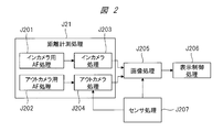
- FIG. 2 is an explanatory diagram showing an example of control transitions in the display device 10 of FIG.
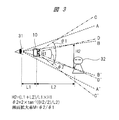
- FIG. 3 is a schematic diagram showing an example of display adjustment by the display device 10 of FIG.
- the transition process shown in FIG. 2 is performed when an AR application or the like stored in the memory unit 104 is activated.
- the image processing unit 103 takes in the sensor information detected by the sensor processing unit 106.
- the distance between the display device 10 and the user who operates the display device 10 (distance L1 in FIG. 3) and the distance between the display device 10 and the target object 32 that the user gazes (distance in FIG. 3). L2) is measured.
- This state J21 is executed by the camera processing unit 102, and is a state J201 that is an in-camera AF process, a state J203 that is an in-camera process, and a state J202 that is an out-camera AF process and an out-camera process.
- State J204 is performed respectively.
- the distance from the display device 10 to the user's eyes 31 is measured using the in-camera 1021 and the AF sensor 1022. Further, the distance from the display device 10 to the object 32 is measured using the out camera 1023 and the AF sensor 1024.
- state J201 which is the in-camera AF processing
- the AF sensor 1022 extracts the distance information from the display device 10 to the user's eye 31.
- the AF sensor 1022 extracts the face of the user imaged by the in-camera 1021 and recognizes the user's eyes 31 to extract the eye position information.
- the image processing unit 103 obtains the distance information L1 from the display device 10 shown in FIG. 3 to the user's eyes 31 based on the distance information and the eye position information described above.
- the distance information from the display device 10 to the target object 32 is extracted.
- the AF sensor 1024 The image processing unit 103 obtains the distance information L2, which is the distance from the display device 10 to the target object 32 shown in FIG. 3, by determining the in-focus point where the focus of the target object 32 captured by the out camera 1023 matches.
- ranges A to A'shown in FIG. 3 indicate the range of the user's visual field
- ranges B to B' show the range in which the display device 10 blocks the visual field
- ranges C to C' show the shooting range of the out camera 1023
- the ranges D to D' show the range of images captured by the out camera 1023.
- the user should focus on an object existing near the center of the display screen as the center of the display screen of the display unit 107 as a gazing point when the user views the display device 10. To work.
- the states J201, J203 and the states J202, J204 may be executed at different timings, or the states J201, J203 and the states J202, J204 may be executed at substantially the same timing.
- the image processing unit 103 outputs the information based on the distance information L1 acquired in the state J203, the distance information L2 acquired in the state J204, and the sensor information acquired in the state J207. Processing such as cutting out, enlarging, or reducing the portion actually displayed on the display unit 107 is performed from the range captured by the camera 1023.
- the distance L2 which is the distance between the display device 10 and the target object 32 to which the user gazes, may be infinity without the measurement by the AF sensor 1024.
- state J206 which is a display control process
- the display unit 107 displays the image generated by the image processing unit 103 in state J205.
- the display device 10 causes the display unit 107 to display the image displayed by the image processing unit 103 on the display unit 107 and the size of the target object viewed by the user with the eyes 31 so that they are substantially the same.
- the display control is performed so that the real world and the image displayed on the screen, that is, the virtual space, look almost the same.
- the height H2 indicating the height of the range to be displayed on the display device 10 shown in FIG. 3 is the distance L1, the distance L2 described in the control transition of FIG. 2, and the display screen of the display unit 107 of the display device 10. It can be calculated from the height H1 by the following formula.
- the angle of view ⁇ 1 indicating the imaging range of the out-camera 1023 is set to be sufficiently wider than what the user's eyes 31 catch, so that the height H2 at the position of the object 32 from the range captured by the out-camera 1023 is set. If the imaging range is extracted and displayed on the display unit 107, it can be displayed with a sense of size that is approximately the same as the surrounding scenery as viewed from the user 1. In other words, the imaging range of the height H2, which is the display imaging range, is trimmed from the imaging range of the out-camera 1023 and displayed on the display unit 107.
- the lens provided in the out-camera 1023 is a lens having a wide angle of view, that is, a so-called wide-angle lens.
- the wide-angle lens is a fish-eye lens, it is possible to capture a scene in the range of approximately 180 degrees in the vertical and horizontal directions. This makes it possible to take a wide-angle image of the entire front view.
- ⁇ 2 2 ⁇ tan ⁇ 1 ((H2/2)/L2)
- the display device 10 is configured as a panel such as a transparent glass plate, that is, a so-called transparent liquid crystal display.
- This transparent liquid crystal display is a display that transmits the background like glass by changing the polarizing film of the liquid crystal panel to a special film. By applying a predetermined signal to this transparent liquid crystal display, an image is displayed at an arbitrary position and with an arbitrary density.
- the transparency of the displayed image may be set in advance.
- the virtual object can be displayed at the coordinate position linked to the external image based on the detection of the position of the user's eye 31 by the in-camera 1021 and the information such as the angle between the position and the panel.
- FIG. 4 is an explanatory diagram showing an example of an imaging range and a display range by the out-camera 1023 included in the display device 10 of FIG.
- FIG. 4 shows the relationship between the imaging range by the out-camera 1023 and the display range obtained by the above-mentioned formula.
- FIG. 4A shows an example in which a portion of the display range 42 is cut out and displayed from the imaging range 41 of the out camera 1023.
- the display range is, as shown in FIG. 4A, an imaging range of Y1/M and X1/M in which the horizontal and vertical directions are multiplied by 1/M. 42 is enlarged and displayed on the display unit 107 by M times.
- the out-camera 1023 is explained on the assumption that it is attached near the center of the display unit 107, which coincides with the line-of-sight direction of the user. However, regarding the attachment position of the out-camera 1023, It does not need to be limited to the center of the screen.
- the effect setting is set by software such as an MR application, a VR application, or an AR application, and the set setting information is stored in the memory unit 104.
- the CPU 101 recognizes the set effect by reading the setting information stored in the memory unit 104.
- the effect setting may be set, for example, when the software is started, or the effect may be set in the initial setting item of the software. These settings are set from, for example, a menu displayed on the display unit 107.
- FIG. 5 is an explanatory diagram showing an example of the correction of the display range according to the mounting position of the out camera 1023 included in the display device 10 of FIG.
- FIG. 5A shows the relationship between the center point Ct of the display device 10 and the display screen portion of the display unit 107 indicated by the dotted line, and the attachment position P of the out camera 1023. Further, FIG. 5B shows the relationship between the imaging range 41 and the display range 42 of the out camera 1023.
- FIG. 5A when the respective positional relationships are represented by coordinates in the X-axis and Y-axis directions, the attachment position P(X1, Y1) of the out-camera 1023 and the screen center point Ct(0, 0) of the display unit 107 are shown. ).
- the image processing unit 103 shifts the display range extracted from the imaging range 41 from the uncorrected display range 42b by position ⁇ X1 and position ⁇ Y1, respectively. Correction is made so that the display range 42a is obtained. As a result, it is possible to reduce the influence of the display shift due to the mounting position of the out camera 1023.
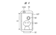
- FIG. 6 is an explanatory diagram showing an example of an image displayed on the display unit included in the display device 10 of FIG.
- the image 321 displayed on the display unit 107 is approximately the same as the object 32 seen from the user by performing the above-described size adjustment of the object 32 in the real space hidden by the display device 10. It is displayed in the same size.
- the virtual image 62 is a virtual object that is not captured and displayed, but is constructed by software such as the VR application, MR application, or AR application described above.
- the virtual image 62 can be matched in size with the captured image by the image processing unit 103 adjusting the display size according to the display magnification M and drawing. As in this example, the virtual image 62 can be arbitrarily arranged in the space of the photographed image.
- a transmissive display device may be used as the display unit 107 as described above.
- the virtual object displays the virtual object that is adjusted in size as described above so that it can be seen through the real space without displaying the captured image.
- the display size adjustment of the virtual object can calculate the size of the imaging area in the real space as described above. Therefore, if the reference size of the virtual object is determined, the display size can be adjusted according to the display enlargement ratio M. it can.
- FIG. 7 is an explanatory diagram showing an example of a display when the display device 10 of FIG. 1 is moved.
- FIG. 7A shows an example in which the display device 10 is moved horizontally or vertically.
- ⁇ X shown in FIG. 7A is the amount of movement of the display device 10 in the horizontal direction
- ⁇ Y is the amount of movement of the display device 10 in the vertical direction.
- the object 32 displayed on the display unit 107 changes from the state shown in FIG. 6 to the display 321 shown in FIG. 7A. Since this is a state in which the display position is simply moved, adjustment can be performed by moving the extraction position of the captured image with the out-camera 1023 in the same manner as described with reference to FIG.
- FIG. 7B shows an example of moving to ⁇ Z which is the vertical direction of the screen in addition to the case of FIG. 7A. 7B is the amount of movement of the display device 10 in the screen vertical direction, that is, the front-back direction.
- the movement amount ⁇ Z is reflected on the distance L1 from the display device 10 to the user and the distance L2 from the display device 10 to the object 32 in the calculation of the enlargement ratio shown in FIG.
- the movement amounts ⁇ X, ⁇ Y, and ⁇ Z can be measured by using the acceleration sensor 1063 shown in FIG.
- the display adjustment is performed again only when the CPU 101 determines that the display device 10 has exceeded the movement amount threshold that is the set movement amount of the measurement value of the acceleration sensor 1063 or the like. As a result, it is possible to suppress an increase in power consumption and frequent changes of the display screen.
- a minute displacement caused by the hand of the user can be suppressed by providing the camera processing unit 102 of FIG. 1 with a camera shake correction function (not shown). As a result, it is possible to reduce the difficulty of viewing the display screen displayed on the display unit 107 due to camera shake.
- the distance from the display device 10 to the user or the object 32 may be measured, for example, by using the distance sensor 1061 in FIG. 1 instead of using the autofocus function of the camera processing unit 102. ..
- the distance sensor 1061 for example, a sensor using infrared rays or ultrasonic waves is used.
- the display device 10 controls the enlargement/reduction so that the virtual object looks almost the same as the appearance in the real space according to the enlargement ratio M. However, by operating the enlargement ratio M, the virtual object is displayed in the real space.
- the display may be made slightly smaller than that of, or conversely slightly larger.
- a magnification setting item regarding display such as enlargement, reduction, or equal magnification may be displayed on the display unit 107 so that the user can select a desired display.
- FIG. 8 is an explanatory diagram showing another example of FIG. 7.
- the display device 10 on hand is shown tilted from a vertical state and moved to a depression angle.
- the imaging range of the out-camera 1023 is the range C to C', as shown in the figure.
- the imaging range of the out-camera 1023 becomes the range C1 to C1'.
- the image processing unit 103 maintains the image in the range blocked by the display device 10 from the user's eyes 31 and displays the image on the display unit 107. ..
- the image in the range blocked by the display device 10 is slightly changed depending on the inclination of the display device 10, but in FIG. 8, it is a range from the approximate range B to the range B′ indicated by hatching. Therefore, the image processing unit 103 causes the display unit 107 to display an image in the range of approximately range B to range B′ even if the imaging range changes due to the change in the tilt of the display device 10.
- the display object viewed by the user on the display screen of the display unit 107 does not move or moves with respect to the outside world of the part not blocked by the display device 10. It is possible to provide an image in which the presence is reduced and the image is realistic.
- FIG. 9 is an explanatory diagram showing an example of the external appearance of the display device 10 of FIG.
- a switching button 2000 which is a software button, is displayed on the display unit 107.
- the switch button 2000 is, for example, a display mode in which an image captured by the out camera 1023 is displayed (hereinafter, referred to as a camera display mode) and a display mode displayed by software such as an AR application that handles virtual objects (hereinafter, referred to as a transparent mode). This button switches between and.
- the user touches the switching button 2000 to switch between the camera display mode and the transparent mode.
- This switching process is executed by the CPU 101 based on a signal input from the button 2000, for example.
- the display mode is the camera display mode or the transparent mode is displayed by changing the display color of the switching button 2000 or changing the characters so that the user can easily determine which mode the display mode is in. Can be grasped.
- a mark that does not support the transparent mode may be superimposed on the application icon.
- the display device 10 is held in the vertically long state, but the display device 10 may be held in the horizontally long state.
- FIG. 10 is an explanatory diagram showing an example of use in the display device 10 according to the second embodiment.
- FIG. 10 an example of using the display device 10 of FIG. 1 by a plurality of persons is shown.
- the display devices 10 and 82 are displayed by the persons 82 and 83. 10 shall be used.
- the method for determining the distance L1 in FIG. 10 will be described below.
- the following processing is mainly performed by the image processing unit 103.
- the image processing unit 103 determines the face of the person on the user side imaged by the in-camera 1021 included in the display device 10. At this time, the person 81, the person 82, and the person 83 are determined as persons. As a result, the image processing unit 103 recognizes that there are a plurality of users.
- the image processing unit 103 which recognizes that there are a plurality of users, determines the distance L1 based on the result of the face determination.
- the method of determining the distance L1 for example, one of the following first determining method, second determining method, third determining method, fourth determining method, or fifth determining method is used. ..
- the first determination method is a method of setting the distance L1 to the person closest to the display device 10 or the person having the largest area imaged by the in-camera 1023 of the display device 10.
- the CPU 101 identifies the person having the largest area among the persons to be imaged, acquires the distance to the identified person measured by the AF sensor 1022 as the distance L1, and outputs it to the image processing unit 103.
- the second determination method is a method in which the distance to the person in the center of the imaging range of the in-camera 1021 is the distance L1. Also in this case, the CPU 101 identifies the person in the center of the imaged persons, acquires the distance to the identified person measured by the AF sensor 1022 as the distance L1, and causes the image processing unit 103 to perform the acquisition. Output.
- the third determination method is a method in which the average value of the respective distances to the persons 80, 81, 82 imaged by the in-camera 1021 is set as the distance L1.
- the CPU 101 acquires the distances to the persons 80, 81, 82 measured by the AF sensor 1022, and calculates the average of the acquired distances. Then, the calculated distance is acquired as the distance L1 and output to the image processing unit 103.
- the fourth determination method is a method in which the distance from the person holding the display device 10 to the display device 10 is the distance L1. From the shake of the image processing unit 103 and the display device 10 held by the hand, the analysis result of the shake direction and the shake width and the shake of the imaged person are taken to determine the person who holds the display device 10. Then, based on the determination result, the distance between the display device 10 and the handle is set as the distance L1.
- the fifth determination method is a method in which the distance from the user registered in advance to the display device 10 is the distance L1.
- the user's face is photographed and registered in advance by the in-camera 1021 or the like.
- the registration result is stored in the memory unit 104, for example.
- the image processing unit 103 performs image recognition of the face captured by the image of the in-camera 1021 when the AR application or the like is activated, and determines that the face that matches the registered face is the user.
- the CPU 101 may recognize the face first captured by the in-camera 1021 as the user and register the face when the AR application or the like is activated. If the registered face has not been photographed for a preset time, the registered face may be deleted and the face currently photographed may be registered as the user.
- the determination method to be selected may be made selectable by setting the display device 10, or a determination method may be set in advance and the setting may be stored in the memory unit 104 as setting information. , AR application may be selected at the time of starting.
- the CPU 101 measures the distance L2 to the object 801 in the same manner as in the example shown in FIG. 3 to obtain the imaging height H2 and the imaging angle of view ⁇ 2 at that time, and calculates the display magnification ratio M.
- an image such as a virtual object can be displayed on the display device 10 as if a part of the real world was extracted.
- the display image of the display device 10 viewed by a plurality of people and the real image of the visual field viewed by each person may differ due to some deviation in the line-of-sight direction. is there.
- the image processing unit 103 sets the enlargement ratio smaller than the value of the display enlargement ratio M, and displays a wider range than the area hidden by the display device 10. Thereby, any user who is looking at the display device 10 can see the image in the line-of-sight direction. As a result, the usability of the display device 10 can be improved.
- the display enlargement ratio M can be changed according to the number of persons recognized by the in-camera 1021. If the number of persons captured by the in-camera 1021 is one, the display magnification ratio M1 is set, and if the number of persons is two, the magnification ratio M2 is set. The display is adjusted according to the number of people, which improves usability. Here, it is assumed that M1>M2>M3.
- the virtual object in an appropriate size on the display image by constructing the virtual object in accordance with the enlargement ratio described above.
- the display device 10 may construct an AR image by projecting it on a projection plate by a device such as a projector instead of a mobile terminal such as a smartphone or a tablet terminal.
- the display device 10 In the first and second embodiments, the example in which the display device 10 is held in the vertically long state is shown, but the display device 10 may be held in the horizontally long state.
- part of the configuration of one embodiment can be replaced with the configuration of another embodiment, and the configuration of one embodiment can be added to the configuration of another embodiment. .. Further, with respect to a part of the configuration of each embodiment, other configurations can be added, deleted, or replaced.
Landscapes
- Engineering & Computer Science (AREA)
- Theoretical Computer Science (AREA)
- General Engineering & Computer Science (AREA)
- Physics & Mathematics (AREA)
- General Physics & Mathematics (AREA)
- Human Computer Interaction (AREA)
- Multimedia (AREA)
- Signal Processing (AREA)
- Computer Hardware Design (AREA)
- Computer Graphics (AREA)
- Software Systems (AREA)
- Computer Vision & Pattern Recognition (AREA)
- Controls And Circuits For Display Device (AREA)
- Processing Or Creating Images (AREA)
- Image Processing (AREA)
- Closed-Circuit Television Systems (AREA)
- Transforming Electric Information Into Light Information (AREA)
- User Interface Of Digital Computer (AREA)
Abstract
仮想空間が実空間と等価となるように表示することにより、違和感のない仮想空間を提供する。表示装置10において、AFセンサ1022は、インカメラ1022が撮像する利用者の目を識別して、識別した目からインカメラ1022までの第1の距離を計測する。AFセンサ1024は、アウトカメラ1023から該アウトカメラ1023が撮像する対象物までの第2の距離を計測する。画像処理部103は、AFセンサ1022が計測した第1の距離、AFセンサ1024が計測した第2の距離、および表示部107の高さに基づいて、該表示部107に表示する表示撮像範囲を算出して、算出した表示撮像範囲をアウトカメラ1023が撮像する画像から抽出して表示部107に表示させる。画像処理部103が算出する表示撮像範囲は、表示部107に表示される対象物と利用者の視点から見る表示部107にて遮蔽されない外界の景色とが同じサイズとなる範囲である。
Description
本発明は、表示装置に関し、特に、仮想現実画像に仮想オブジェクトを重畳表示させる画像処理に有効な技術に関する。
近年、MR(Mixed Reality)、VR(Virtual Reality)、あるいはAR(Article Reality)技術に代表される画像処理技術の進展や画像処理した結果を表示するHMD(Head Mount Display)、タブレット端末、スマートフォン端末などの表示装置を含む電子端末の高性能化に伴い、実空間や仮想現実映像の画像に仮想オブジェクトを重畳表示させるコンテンツやその装置などが多数開発されている。
この主の画像表示技術としては、例えばカメラで撮影した画像を表示させながら電子機器に対する操作を受け付けることによって撮影した画像を見ながら電子機器の操作をするもの(例えば特許文献1参照)がある。
その他の画像表示技術としては、表示画面にて撮影者の視界が遮られる領域をカメラで撮像し、表示画面にて撮影者の視界が遮られる領域を表示画面に表示するもの(例えば特許文献2参照)あるいは画面を見る視認者の視線方向に応じた画像を表示することにより、リアリティに富んだ画像表示を実現するもの(例えば特許文献3参照)などが知られている。
上述した特許文献1~3の技術では、表示部に撮像画像を表示する際に端末の向きや角度の変化やユーザの視線の変化などに対する補正については行われているが、補正した後に表示される画像のサイズなどに対する配慮についてはなされていない。
つまり、電子端末を手持ちした場合などに利用者の視線方向や視距離がずれることによる表示画面の見え方の変化、あるいは電子端末に設けられるカメラの取り付け位置による影響による表示画面のずれなどについては考慮されていない。
その結果、実空間に重畳表示される仮想オブジェクトなどの画像に違和感などが生じてしまうという問題がある。
本発明の目的は、仮想空間が実空間と等価となるように表示することにより、違和感のない仮想空間を提供することのできる技術を提供することにある。
本発明の前記ならびにその他の目的と新規な特徴については、本明細書の記述および添付図面から明らかになるであろう。
本願において開示される発明のうち、代表的なものの概要を簡単に説明すれば、次のとおりである。
すなわち、代表的な表示装置は、第1の撮像部、第1の距離検出部、第2の撮像部、第2の距離検出部、画像処理部、および表示部を有する。第1の撮像部は、第1の面に設けられ、利用者を撮像する。第1の距離検出部は、第1の撮像部が撮像する利用者の目を識別して、識別した目から第1の撮像部までの距離である第1の距離を計測する。
第2の撮像部は、第1の面に対向する第2の面に設けられ、対象物を撮像する。第2の距離検出部は、第2の撮像部から第2の撮像部が撮像する対象物までの距離である第2の距離を計測する。
画像処理部は、第1の撮像部および第2の撮像部が撮像した画像を画像処理する。表示部は、画像処理部が画像処理した画像を表示する。
また、画像処理部は、第1の距離検出部が計測した第1の距離、第2の距離検出部が計測した第2の距離、および表示部の高さに基づいて、表示部に表示する表示撮像範囲を算出して、算出した表示撮像範囲を第2の撮像部が撮像する画像から抽出して表示部に表示させる。
そして、画像処理部が算出する表示撮像範囲は、表示部に表示される対象物と利用者の視点から見る表示部にて遮蔽されない外界の景色とが同じサイズとなる範囲である。
特に、画像処理部は、表示撮像範囲に応じて、表示サイズを調整した仮想映像を生成して表示部に表示させる。
本願において開示される発明のうち、代表的なものによって得られる効果を簡単に説明すれば以下のとおりである。
表示装置に表示される画像の違和感を低減することができる。
実施の形態を説明するための全図において、同一の部材には原則として同一の符号を付し、その繰り返しの説明は省略する。
(実施の形態1)
以下、実施の形態を詳細に説明する。
以下、実施の形態を詳細に説明する。
〈表示装置の構成例〉
図1は、本実施の形態1による表示装置10における構成の一例を示す説明図である。
図1は、本実施の形態1による表示装置10における構成の一例を示す説明図である。
表示装置10は、例えばスマートフォンやタブレット端末などの携帯端末からなる。表示装置10は、図1に示すように、CPU(Central Processing Unit)101、カメラ処理部102、画像処理部103、メモリ部104、通信制御部105、センサ処理部106、表示部107、および音声入出力部108などから構成されている。
CPU101は、メモリ部104に格納されているOS(Operating System)やアプリケーション、あるいは表示装置10の動作を制御する制御プログラムなどを実行することによって、各機能ブロックを制御する。
カメラ処理部102は、インカメラ1021、AFセンサ1022、アウトカメラ1023、およびAFセンサ1024から構成されている。第1の撮像部であるインカメラ1021は、表示装置10の正面側、すなわち表示部107側である第1の面に設けられるカメラである。第1の距離検出部であるAFセンサ1022は、インカメラ1021と表示装置10の利用者との距離を測り、焦点調整を行う。
第2の撮像部であるアウトカメラ1023は、インカメラ1021とは反対側、すなわち第2の面である表示装置10の背面側に備わるカメラである。第2の距離検出部であるAFセンサ1024は、アウトカメラ1023とその撮像対象との距離を測り、焦点調整を行う。
センサ処理部106は、距離センサ1061、ジャイロセンサ1062、加速度センサ1063、および磁気センサ1064などのセンサ群から構成されている。距離センサ1061は、表示装置10の姿勢や位置などの状態を監視するセンサである。
ジャイロセンサ1062は、表示装置10の回転方向の角速度を検出するセンサである。加速度センサ1063は、加速度を検出するセンサであり、重力を検出することができる。この加速度センサ部1063による重力の検出によって表示装置10の傾きなどを検出する。磁気センサ1064は、地磁気を検出するセンサであり、方角を検知することができる。
画像処理部103は、いわゆるGPU(Graphic Processing Unit)と呼ばれる画像処理装置であり、例えばMR、VR、あるいはARなどの画像処理を行う。表示部107は、表示デバイスおよび該表示デバイスを駆動制御する駆動制御部から構成されており、画像処理部103が画像処理した画像などを表示する。表示デバイスは、例えば液晶表示デバイスや有機EL(Electro Luminescence)デバイスなどである。
メモリ部104は、例えばフラッシュメモリなどに例示される半導体メモリなどからなり、上述したアプリケーション、OSおよび制御プログラム、および設定情報などの様々な情報を格納する。
上述したメモリ部104に格納されるアプリケーションは、仮想オブジェクトなどを取り扱うアプリケーションであるARアプリケーション、VRアプリケーション、およびMRアプリケーションなどである。
通信制御部105は、無線LAN(Local Area Network)によりルータなどと無線通信を行う通信インターフェースであり、該ルータなどを介して外部ネットワークに接続して情報の送受信を行う。
あるいは、通信制御部105は、W-CDMA(Wideband Code Division Multiple Access)やGSM(Global System for Mobile Communications)(登録商標)などの基地局と遠距離の無線通信を行う通信インターフェースであってもよい。
音声入出力部108は、外部の音声を入力するマイクや外部に対して音声を出力するスピーカなどからなる。
〈表示装置の表示処理例〉
続いて、表示装置10による表示方法について、図2および図3を用いて説明する。
続いて、表示装置10による表示方法について、図2および図3を用いて説明する。
図2は、図1の表示装置10における制御遷移の一例を示す説明図である。図3は、図1の表示装置10による表示調整の一例を示す模式図である。図2に示す遷移処理については、メモリ部104に格納されるARアプリケーションなどが起動された際に行われるものである。
図2において、センサ処理である状態J207では、画像処理部103が、センサ処理部106が検出するセンサ情報を取り込む。状態J21では、表示装置10と該表示装置10の操作を行う利用者までの距離(図3の距離L1)、および表示装置10と利用者が注視する対象物32までの距離(図3の距離L2)を測定する。
この状態J21は、カメラ処理部102が実行するものであり、インカメラ用AF処理である状態J201とインカメラ処理である状態J203、およびアウトカメラ用AF処理である状態J202とアウトカメラ処理である状態J204が、それぞれ行われる。
状態J21では、表示装置10から利用者の目31までの距離をインカメラ1021およびAFセンサ1022を用いて測定する。また、表示装置10から対象物32までの距離をアウトカメラ1023およびAFセンサ1024を用いて測定する。
インカメラ用AF処理である状態J201では、AFセンサ1022が表示装置10から利用者の目31までの距離情報を抽出する。続いて、インカメラ処理である状態J203では、AFセンサ1022がインカメラ1021の撮像する利用者の顔を抽出して、該利用者の目31を認識することによって目の位置情報を抽出する。
これにより、画像処理部103は、上述した距離情報および目の位置情報に基づいて、図3に示す表示装置10から利用者の目31までの距離情報L1を得る。
同様にして、アウトカメラ用AF処理である状態J202およびアウトカメラ処理である状態J204では、表示装置10から対象物32までの距離情報を抽出することになるが、この場合、AFセンサ1024は、アウトカメラ1023で撮像する対象物32のフォーカスが合致する合焦点を決定することにより、画像処理部103が、図3に示す表示装置10から対象物32までの距離である距離情報L2を得る。
ここで、図3に示す範囲A~A’は、利用者の視野の範囲を示しており、範囲B~B’は、視野が表示装置10によって遮られる範囲を示している。また、範囲C~C’は、アウトカメラ1023の撮影範囲を示しており、範囲D~D’は、アウトカメラ1023が取り込む画像の範囲を示している。
アウトカメラ1023にて撮像する対象の設定に関しては、利用者が表示装置10を見る際の注視点として表示部107の表示画面の中心付近として、該表示画面の中心付近に存する物体にフォーカスするように動作させる。
これら状態J201,J203と状態J202,J204とは、異なるタイミングにて実行してもよいし、あるいは状態J201,J203と状態J202,J204とをほぼ同じタイミングにて実行するようにしてもよい。
次に、画像処理を行う状態J205では、画像処理部103が状態J203にて取得した距離情報L1、状態J204にて取得した距離情報L2、および状態J207にて取り込んだセンサ情報に基づいて、アウトカメラ1023が撮像する範囲から実際に表示部107に表示する部分の切り出しや拡大あるいは縮小などの処理を行う。
ここで、表示装置10と利用者が注視する対象物32までの距離である距離L2については、AFセンサ1024による測定を行わずに無限遠としてもよい。表示制御処理である状態J206では、表示部107が状態J205において画像処理部103が生成した画像を表示する。
このように、表示装置10は、画像処理部103が表示部107に表示させる画像と利用者が目31で見ている対象物との大きさを概ね統一させて表示部107に表示させることによって、実世界と画面上に表示させる画像で、すなわち仮想空間とが概ね同じように見えるように表示制御を行う。
以下では、アウトカメラ1023の撮像映像から上述した表示制御の主旨に沿って表示部107に表示するまでの方法について記す。
図3に示す表示装置10にて表示すべき範囲の高さを示す高さH2は、図2の制御遷移にて述べた距離L1、距離L2、および表示装置10における表示部107の表示画面の高さH1から下記の式にて求めることができる。
H2=(L1+L2)/L1×H1
また、アウトカメラ1023の撮像範囲を示す画角θ1は、利用者の目31が捉えるよりも十分に広く設定することによって、アウトカメラ1023にて撮像する範囲から物体32の位置で高さH2の撮像範囲を抽出して表示部107に表示すれば利用者1から見て周囲の景色と概ね同等のサイズ感によって表示することができる。言い換えれば、アウトカメラ1023にて撮像する範囲から表示撮像範囲となる高さH2の撮像範囲をトリミングして表示部107に表示する。
また、アウトカメラ1023の撮像範囲を示す画角θ1は、利用者の目31が捉えるよりも十分に広く設定することによって、アウトカメラ1023にて撮像する範囲から物体32の位置で高さH2の撮像範囲を抽出して表示部107に表示すれば利用者1から見て周囲の景色と概ね同等のサイズ感によって表示することができる。言い換えれば、アウトカメラ1023にて撮像する範囲から表示撮像範囲となる高さH2の撮像範囲をトリミングして表示部107に表示する。
よって、アウトカメラ1023に設けられるレンズは、広い画角を有するレンズ、いわゆる広角レンズであることが望ましい。広角レンズが魚眼レンズである場合には、上下左右方向のほぼ180度にわたる範囲の光景を取り込むことができる。これによって、前面側全景を広角に撮影することが可能となる。
抽出する撮像範囲の求め方は、図3に示す画角θ2を以下の式で算出する。
θ2=2×tan-1((H2/2)/L2)
以上より、表示部107が表示する画像は、拡大率M=θ2/θ1にて表示され、利用者からの見た目は、表示部107に隠される部分に存する物体と概ね同様の大きさとなる。
以上より、表示部107が表示する画像は、拡大率M=θ2/θ1にて表示され、利用者からの見た目は、表示部107に隠される部分に存する物体と概ね同様の大きさとなる。
ところで、撮像範囲の画像の取得および表示の方法として、アウトカメラ1023による外部画像の取得および表示は、不要とすることもできる。この場合、例えば表示装置10を、それ自体が透明なガラス板のようなパネル、いわゆる透明液晶ディスプレイなどに構成する。
この透明液晶ディスプレイは、液晶パネルの偏光フィルムを特殊フィルムに変更することによって、ガラスのように背景を透過させるディスプレイである。この透明液晶ディスプレイに所定の信号を与えることにより、任意の位置に任意の濃さにて画像が表示される。
これにより、背景を透過したディスプレイ越しに見みることができるので、該透明液晶ディスプレイには、仮想オブジェクトのみを表示させればよい。なお、表示される画像の濃さについては、予め設定される透明度を設定するようにしてもよい。
仮想オブジェクトは、インカメラ1021によるユーザの目31の位置の検出、およびその位置とパネルとの角度などの情報から、外界イメージとリンクした座標位置に表示することも可能である。
〈撮像範囲および表示範囲の例〉
図4は、図1の表示装置10が有するアウトカメラ1023による撮像範囲および表示範囲の一例を示す説明図である。
図4は、図1の表示装置10が有するアウトカメラ1023による撮像範囲および表示範囲の一例を示す説明図である。
この図4は、先述の式により求められるアウトカメラ1023による撮像範囲と表示範囲との関係を示したものである。
図4(a)は、アウトカメラ1023の撮像範囲41から表示範囲42の部分を切り出して表示する例を示している。この場合、撮像範囲41の解像度を縦方向Y1、横方向X1とすると、表示範囲は、図4(a)に示すように、縦横を1/M倍したY1/M,X1/Mの撮像範囲42を表示部107にM倍拡大して表示される。
一方、図4(b)は、アウトカメラ1023の初期設定画角θ1を画角θ2となるようにアウトカメラ1023のレンズ光学系による拡大処理によって、M倍の拡大表示を行って表示する例を示している。この時、表示倍率Mは、M=θ1/θ2となり、撮像範囲42には変わりはない。
以上の説明では、アウトカメラ1023が利用者の視線方向と合致する略表示部107の中央付近に取り付けられていることを前提に説明しているが、該アウトカメラ1023の取り付け位置については、表示画面の中央付近に限る必要はない。
先述したように、図4では、視線の先が表示装置10の画面中央を向いている例について説明した。この場合、両目のうち、効き目を対象に表示することによって、より現実の世界を目視している状態を作りだせる。
そのためには、距離測定の際に効き目側を起点として距離L1を測定して表示調整を行えばよい。効き目の設定は、例えばMRアプリケーション、VRアプリケーション、あるいはARアプリケーションなどのソフトウェアにより設定され、該設定された設定情報は、メモリ部104に格納される。CPU101は、メモリ部104に格納される設定情報を読み出すことにより、設定された効き目を認識する。
効き目の設定は、例えばソフトウェアの起動時に設定するようにしてよいし、あるいはソフトウェアの初期設定項目にて、効き目の設定を行ってもよい。これらの設定は、例えば表示部107に表示されるメニューなどから設定される。
〈表示補正例〉
図5は、図1の表示装置10が有するアウトカメラ1023の取り付け位置による表示範囲の補正の一例を示す説明図である。
図5は、図1の表示装置10が有するアウトカメラ1023の取り付け位置による表示範囲の補正の一例を示す説明図である。
図5(a)は、表示装置10と点線にて示す表示部107の表示画面部分の中心点Ctとアウトカメラ1023の取り付け位置Pとの関係を示したものである。また、図5(b)は、アウトカメラ1023の撮像範囲41および表示範囲42の関係を示したものである。
図5(a)において、それぞれの位置関係をX軸、Y軸方向の座標にて表すと、アウトカメラ1023の取付位置P(X1,Y1)、表示部107の画面中心点Ct(0,0)であるとする。
このとき、画像処理部103は、図5(b)に示すように、撮像範囲41の中から抽出する表示範囲を補正前の表示範囲42bからそれぞれ位置-X1、位置-Y1だけ位置をずらした表示範囲42aとなるように補正する。これにより、アウトカメラ1023の取り付け位置による表示ずれの影響を軽減することができる。
なお、前述した方法は、撮像範囲>表示範囲の関係であれば、図4(a)および図4(b)のどちらの場合にも適用可能である。
以上の補正により、表示装置10を利用者が手持ちなどにより、実空間上にて様々な方向に向けて表示するような使い方の場合であっても、利用者の目線と概ね同じようにアウトカメラ1023にて撮像される対象物を表示した画像を見ることができる。
図5に示した補正による表示状態について、図6を用いて説明する。
図6は、図1の表示装置10が有する表示部に表示される画像の一例を示す説明図である。
表示部107に表示される画像321は、図6に示すように、表示装置10によって隠れる実空間上の物体32を上述のサイズ調整などを行うことによって、利用者から見て該物体32と概ね同じサイズとなって表示される。
これにより、現実の世界と表示装置10にて構築される仮想空間との連携を違和感なく、自然に楽しむことができる。
なお、図6において、仮想画像62は、撮像されて表示するものではなく、上述したVRアプリケーション、MRアプリケーション、あるいはARアプリケーションなどのソフトウェアによって構築される仮想オブジェクトである。
この仮想画像62は、画像処理部103が表示倍率Mに応じて、その表示サイズを調整して描画することにより、撮像画像との大きさの整合性を取ることができる。この例のように、仮想画像62は、実写映像の空間に対して任意に配することができる。
なお、本実施の形態1では、撮像画像上に仮想オブジェクトを重畳する例について示しているが、上述したように表示部107に透過型の表示デバイスを用いることもできる。その場合、仮想オブジェクトは、撮像画像を表示せずに実空間を透過して眺められるようにして、上述の通りにサイズ調整した仮想オブジェクトを表示する。
仮想オブジェクトの表示サイズ調整は、実空間の撮像エリアのサイズを上述の通り算出可能であるため、仮想オブジェクトの基準サイズを決定しておけば表示拡大率Mに合わせて表示サイズを調整することができる。
〈XYZ軸方向の動き補正〉
続いて、利用者が手持ちしている表示装置10を動かしたり、見ている方向を変える動作を行った場合について、図7を用いて説明する。
続いて、利用者が手持ちしている表示装置10を動かしたり、見ている方向を変える動作を行った場合について、図7を用いて説明する。
図7は、図1の表示装置10を移動させた際の表示の一例を示す説明図である。
図7(a)は、表示装置10を水平方向あるいは垂直方向にそれぞれ動かした例を示している。図7(a)に示すΔXは、水平方向における表示装置10の移動量であり、ΔYは、垂直方向の表示装置10の移動量である。
この場合、表示部107に表示される物体32は、図6に示す状態から図7(a)に示す表示321のように変化する。これは、表示位置が単に移動した状態であるので、アウトカメラ1023にて撮像画像の抽出位置を図5(b)の説明と同様に移動させることで調整が可能である。
図7(b)は、図7(a)の場合に加えて、画面鉛直方向であるΔZに移動している例を示している。図7(b)に示すΔZは、画面鉛直方向、すなわち前後方向における表示装置10の移動量である。
この図7(b)では、図3に示した拡大率の計算における表示装置10から利用者までの距離L1、および表示装置10から物体32までの距離L2に対して移動量ΔZを反映させることによって、移動後の拡大率を算出することができる。なお、移動量ΔX,ΔY,ΔZは、図1の加速度センサ1063などを用いることによって測定可能である。
また、表示装置10が加速度センサ1063などの測定値が設定された動き量である移動量しきい値を越えたとCPU101が判断した場合にのみ、再度表示調整を行うようにする。これにより、消費電力の増大や表示画面の頻繁な変更を抑えることができる。
また、利用者の手持に伴う微小な変位は、図1のカメラ処理部102に図示しない手振れ補正機能を備えることによって抑制することができる。これにより、表示部107に表示される表示画面が手振れで見難くなることを軽減することができる。
また、表示装置10から利用者や物体32までの距離は、カメラ処理部102のオートフォーカス機能を用いて計測するのではなく、例えば図1の距離センサ1061を用いて測定するようにしてもよい。その場合、距離センサ1061は、例えば赤外線や超音波などを用いたセンサが用いられる。
さらに、表示装置10は、拡大率Mによって仮想オブジェクトが実空間上の見え方とほぼ同様に見えるように拡大縮小を制御しているが、該拡大率Mを操作して、仮想オブジェクトを実空間の見え方よりも僅かに小さくしたり、あるいは逆に僅かに大きくして表示するようにしてもよい。
これによって、表示装置10の利用者にとって実空間との関係性を把握しやすくすることができる。この場合、拡大、縮小、あるいは等倍といった表示に関する倍率設定項目を表示部107に表示して、利用者が好みの表示を選択可能としてもよい。
〈動き補正の他の例〉
図8は、図7の他の例を示す説明図である。
図8は、図7の他の例を示す説明図である。
この図8では、手持ちの表示装置10が垂直の状態から傾いて俯角となるように動いた状態を示している。
表示装置10が垂直の状態では、図示するように、アウトカメラ1023の撮像範囲が範囲C~C’までとなる。図8の点線にて示すように表示装置10が垂直の状態から俯角に傾くと、アウトカメラ1023の撮像範囲は、範囲C1~C1’までとなる。
表示装置10の傾きが変化することによって撮像範囲が変化しても、画像処理部103は、利用者の目31からみて表示装置10に遮られる範囲の画像を維持して表示部107に表示する。
この場合、表示装置10に遮られる範囲の画像は、表示装置10の傾きにより多少変わるが、図8では、ハッチングにて示す略範囲B~範囲B’の範囲となる。よって、画像処理部103は、表示装置10の傾きが変化することによって撮像範囲が変化しても、略範囲B~範囲B’の範囲の画像を表示部107に表示させる。
これにより、手持ちなどによって表示装置10の傾きが変わっても、使用者が表示部107の表示画面で見る表示対象物が該表示装置10に遮られない部分の外界に対して動かなくなり、あるいは動きが低減して、臨場感があふれる画像を提供することができる。
〈表示装置の他の構成例〉
図9は、図1の表示装置10における外観の一例を示す説明図である。
図9は、図1の表示装置10における外観の一例を示す説明図である。
図9に示す表示装置10では、表示部107にソフトウェアボタンである切り替えボタン2000が表示されている。
この切り替えボタン2000は、例えばアウトカメラ1023が撮像した画像を表示する表示モード(以下、カメラ表示モードという)と仮想オブジェクトを取り扱うARアプリケーションなどのソフトウェアによって表示される表示モード(以下、透過モードという)とを切り替えるボタンである。
利用者が切り替えボタン2000をタッチすることによって、カメラ表示モードと透過モードとの切り替えが行われる。この切り替えの処理は、例えばCPU101がボタン2000から入力される信号に基づいて実行する。
カメラ表示モードになっているか、あるいは透過モードになっているかは、切り替えボタン2000の表示の色を変える、あるいは文字を変えるなどにて表示することにより、いずれのモードであるかを利用者が容易に把握することができる。
さらに、ARアプリケーションなどにおいて、透過モードに対応しないものもある場合は、アプリアイコンに透過モード非対応のマークを重畳表示してもよい。
また、図3~図8に示す各例では、表示装置10を縦長の状態にて保持する例を示しているが、該表示装置10は、横長の状態にて保持するようにしてもよい。
以上により、実世界と画面上に表示させる画像とが略同じに見えるように連携を保ちながら表示させることにより、利用者が感じる違和感を低減することができる。
(実施の形態2)
〈複数人での利用例〉
本実施の形態2においては、表示装置10を多人数によって利用する場合の例について説明する。
〈複数人での利用例〉
本実施の形態2においては、表示装置10を多人数によって利用する場合の例について説明する。
図10は、本実施の形態2による表示装置10における利用の一例を示す説明図である。
この図10では、図1の表示装置10を複数の人物によって利用する際の例を示したものであり、ここでは、表示装置10の持ち主である人物81以外に、人物82,83によって表示装置10を利用するものとする。
以下、図10において、距離L1を判定する方法をについて述べる。以下の処理は、画像処理部103が主体となって行うものである。
まず、画像処理部103は、表示装置10に備わるインカメラ1021にて撮像される利用者側の人物の顔判定を行う。この際、人物81、人物82、および人物83が人物として判定される。これにより、画像処理部103は、利用者が複数であることを認識する。
利用者が複数であることを認識した画像処理部103は、顔判定の結果に基づいて、距離L1を決定する。この場合、距離L1の決定方法としては、例えば以下に示す第1の決定方法、第2の決定方法、第3の決定方法、第4の決定方法、あるいは第5の決定方法のいずれかを用いる。
第1の決定方法は、表示装置10に最も近い人物、あるいは表示装置10のインカメラ1023にて撮像される面積の最も大きな人物までを距離L1とする方法である。CPU101は、撮像される人物のうち、最も面積の最も大きな人物を特定し、AFセンサ1022が計測した特定した人物までの距離を距離L1として取得して画像処理部103に出力する。
第2の決定方法は、インカメラ1021による撮像範囲のうち、最も中央部にいる人物までの距離を距離L1とする方法である。この場合においても、CPU101は、撮像される人物のうち、最も中央部にいる人物を特定して、AFセンサ1022が計測した特定した人物までの距離を距離L1として取得して画像処理部103に出力する。
第3の決定方法は、インカメラ1021により撮像されている人物80,81,82までのそれぞれの距離の平均値を距離L1とする方法である。この場合、CPU101は、AFセンサ1022が計測した人物80,81,82までの距離を取得して、取得した距離の平均を算出する。そして、算出した距離を距離L1として取得して画像処理部103に出力する。
第4の決定方法は、表示装置10を持ち手している人物から表示装置10までの距離を距離L1とする方式である。画像処理部103、表示装置10の手持による揺れから当該揺れ方向と揺れ幅との解析結果および撮像される人物の揺れ方との相関を取り、表示装置10の持ち手である人物を判定する。そして、その判定結果に基づいて、表示装置10の持ち手との距離を距離L1とする。
第5の決定方法は、予め登録した利用者から表示装置10までの距離を距離L1する方法である。この場合、インカメラ1021などによって予め利用者の顔を撮影して登録する。その登録結果は、例えばメモリ部104に格納される。画像処理部103は、ARアプリケーションなどが起動した際にインカメラ1021の画像がとらえた顔を画像認識して、登録された顔と一致した顔を利用者と判断する。
また、第5の決定方法としては、例えばARアプリケーションなどが起動した際にCPU101がインカメラ1021によって最初にとらえられた顔を利用者と認識して登録するようにしてもよい。登録した顔が予め設定した時間写っていない場合には、登録済みの顔を消去して、新たに現在写っている顔を利用者として登録するようにしてもよい。
どの決定方法を選択するかについては、表示装置10の設定により選択可能とすることようにしてもよいし、予め判定方式を設定しておき、その設定を設定情報としてメモリ部104に格納して、ARアプリケーションなどの起動時などに選択可能としてもよい。
続いて、CPU101は、対象物801までの距離L2を、図3に示した例と同様に計測して撮像高さH2、その時の撮像画角θ2を求めて、表示拡大率Mを算出する。これによって、実世界の一部分を抽出したような感覚で表示装置10に仮想オブジェクトなどの画像を表示することができる。
この時に、多人数によって表示装置10を見る場合には、複数人から見る表示装置10の表示画像とそれぞれの人物が目視する視野の実像とが視線方向の多少のズレによって異なってくる可能性がある。
そこで、画像処理部103は、表示拡大率Mの値よりも拡大率を小さく設定して、表示装置10により隠れるエリアよりも広い範囲を表示する。それにより、表示装置10を見ている利用者の誰からでも視線方向の画像を見ることができる。その結果、表示装置10の使い勝手を向上することができる。
例えば、表示拡大率Mは、インカメラ1021にて認識する人物の数に応じて変更させることもできる。インカメラ1021が捉える撮像人物が1人の場合は、表示拡大率M1とし、2人の時は拡大率M2、3人の場合は拡大率M3となるように設定すれば、表示装置10を見る人数に応じて表示調整が実施されるので使い勝手がよくなる。ここでM1>M2>M3・・・とする。
また、前記実施の形態1と同様に、上述した拡大率に合わせて、仮想オブジェクトを構築することによって表示画像上に適切な大きさで仮想オブジェクトを配置することが可能となる。
なお、表示装置10は、例えばスマートフォンやタブレット端末などの携帯端末ではなく、プロジェクタなどの機器により投影板に投射することによってAR画像を構築するようにしてもよい。
この場合は、画面が大きいため、より多くの人が同時に閲覧するという状況が発生するが、図9にて説明したように、視聴している各々の人や、全員が見るときに可能な限り違和感が最小になるように照射を行う。
これらにより、多人数の利用者にて表示装置10を利用する際においても、画面上に表示させる画像を実世界との連携を保ちながら表示させることができるで、利用者が感じる違和感を低減することができる。
以上、本発明者によってなされた発明を実施の形態に基づき具体的に説明したが、本発明は前記実施の形態に限定されるものではなく、その要旨を逸脱しない範囲で種々変更可能であることはいうまでもない。
前記実施の形態1、2においては、表示装置10を縦長の状態にて保持する例を示しているが、該表示装置10は、横長の状態にて保持するようにしてもよい。
なお、本発明は上記した実施の形態に限定されるものではなく、様々な変形例が含まれる。例えば、上記した実施の形態は本発明を分かりやすく説明するために詳細に説明したものであり、必ずしも説明した全ての構成を備えるものに限定されるものではない。
また、ある実施の形態の構成の一部を他の実施の形態の構成に置き換えることが可能であり、また、ある実施の形態の構成に他の実施の形態の構成を加えることも可能である。また、各実施の形態の構成の一部について、他の構成の追加、削除、置換をすることが可能である。
10 表示装置
101 CPU
102 カメラ処理部
103 画像処理部
104 メモリ部
105 通信制御部
106 センサ処理部
107 表示部
108 音声入出力部
1021 インカメラ
1022 AFセンサ
1023 アウトカメラ
1024 AFセンサ
1061 距離センサ
1062 ジャイロセンサ
1063 加速度センサ
1064 磁気センサ
101 CPU
102 カメラ処理部
103 画像処理部
104 メモリ部
105 通信制御部
106 センサ処理部
107 表示部
108 音声入出力部
1021 インカメラ
1022 AFセンサ
1023 アウトカメラ
1024 AFセンサ
1061 距離センサ
1062 ジャイロセンサ
1063 加速度センサ
1064 磁気センサ
Claims (12)
- 第1の面に設けられ、利用者を撮像する第1の撮像部と、
前記第1の撮像部が撮像する前記利用者の目を識別して、識別した前記目から前記第1の撮像部までの距離である第1の距離を計測する第1の距離検出部と、
前記第1の面に対向する第2の面に設けられ、対象物を撮像する第2の撮像部と、
前記第2の撮像部から前記第2の撮像部が撮像する前記対象物までの距離である第2の距離を計測する第2の距離検出部と、
前記第1の撮像部および前記第2の撮像部が撮像した画像を画像処理する画像処理部と、
前記画像処理部が画像処理した画像を表示する表示部と、
を有し、
画像処理部は、前記第1の距離検出部が計測した前記第1の距離、前記第2の距離検出部が計測した前記第2の距離、および前記表示部の高さに基づいて、前記表示部に表示する表示撮像範囲を算出して、算出した前記表示撮像範囲を前記第2の撮像部が撮像する画像から抽出して前記表示部に表示させ、
前記画像処理部が算出する前記表示撮像範囲は、前記表示部に表示される前記対象物と前記利用者の視点から見る前記表示部にて遮蔽されない外界の景色とが同じサイズとなる範囲である、表示装置。 - 請求項1記載の表示装置において、
前記画像処理部は、前記表示撮像範囲に応じて、表示サイズを調整した仮想画像を生成して前記表示部に表示させる、表示装置。 - 請求項1記載の表示装置において、
前記画像処理部は、算出した前記表示撮像範囲よりも小さい画像範囲を前記第2の撮像部が撮像する撮像範囲からトリミングして前記表示部に表示させる、表示装置。 - 請求項1記載の表示装置において、
前記表示装置の移動量を検出する検出部を有し、
前記画像処理部は、前記検出部が検出した検出結果に基づいて、前記表示装置の移動後の前記表示撮像範囲を算出して、算出した前記表示撮像範囲を前記第2の撮像部が撮像する画像から抽出して前記表示部に表示させる、表示装置。 - 請求項4記載の表示装置において、
前記検出部は、前記表示装置の水平方向の移動量および前記表示装置の垂直方向の移動量を検出する、表示装置。 - 請求項4記載の表示装置において、
前記検出部は、前記表示装置の水平方向の移動量、前記表示装置の垂直方向の移動量、および前記表示装置の前後方向の移動量を検出する、表示装置。 - 請求項4記載の表示装置において、
前記画像処理部は、前記検出部が検出した移動量が予め設定されている移動量しきい値を超えた際に前記表示撮像範囲を算出する、表示装置。 - 請求項1記載の表示装置において、
前記画像処理部は、前記第1の撮像部が撮像した前記利用者の画像から前記利用者が複数であるか否かを判定し、前記利用者が複数であると判定した際には、複数の前記利用者の前記目から前記第1の撮像部までのそれぞれ距離の平均値を算出して、算出した前記平均値を前記第1の距離とする、表示装置。 - 請求項1記載の表示装置において、
前記画像処理部は、前記第1の撮像部が撮像した前記利用者の画像から前記利用者が複数であるか否かを判定し、前記利用者が複数であると判定した際には、複数の前記利用者のうち、最も撮像面積の大きい利用者の目から前記第1の撮像部までの距離を前記第1の距離とする、表示装置。 - 請求項1記載の表示装置において、
前記画像処理部は、前記第1の撮像部が撮像した前記利用者の画像から前記利用者が複数であるか否かを判定し、前記利用者が複数であると判定した際には、前記第1の撮像部が撮像した前記画像の最も中央部に近い位置の利用者の前記目から前記第1の撮像部までの距離を前記第1の距離とする、表示装置。 - 請求項1記載の表示装置において、
前記画像処理部は、前記第1の撮像部が撮像した前記利用者の画像から前記利用者が複数であるか否かを判定し、前記利用者が複数であると判定した際には、算出した前記表示撮像範囲よりも小さい画像範囲を前記第2の撮像部が撮像する撮像範囲からトリミングして前記表示部に表示させる、表示装置。 - 請求項11記載の表示装置において、
前記画像処理部は、前記利用者の人数に応じてトリミングする前記画像範囲のサイズを変更する、表示装置。
Priority Applications (6)
| Application Number | Priority Date | Filing Date | Title |
|---|---|---|---|
| PCT/JP2018/044149 WO2020110283A1 (ja) | 2018-11-30 | 2018-11-30 | 表示装置 |
| JP2020557504A JP7146944B2 (ja) | 2018-11-30 | 2018-11-30 | 表示装置 |
| US17/298,027 US11483483B2 (en) | 2018-11-30 | 2018-11-30 | Display apparatus |
| CN201880099911.0A CN113170077A (zh) | 2018-11-30 | 2018-11-30 | 显示装置 |
| JP2022150100A JP7427739B2 (ja) | 2018-11-30 | 2022-09-21 | 表示装置 |
| US17/949,223 US11831976B2 (en) | 2018-11-30 | 2022-09-21 | Display apparatus |
Applications Claiming Priority (1)
| Application Number | Priority Date | Filing Date | Title |
|---|---|---|---|
| PCT/JP2018/044149 WO2020110283A1 (ja) | 2018-11-30 | 2018-11-30 | 表示装置 |
Related Child Applications (2)
| Application Number | Title | Priority Date | Filing Date |
|---|---|---|---|
| US17/298,027 A-371-Of-International US11483483B2 (en) | 2018-11-30 | 2018-11-30 | Display apparatus |
| US17/949,223 Continuation US11831976B2 (en) | 2018-11-30 | 2022-09-21 | Display apparatus |
Publications (1)
| Publication Number | Publication Date |
|---|---|
| WO2020110283A1 true WO2020110283A1 (ja) | 2020-06-04 |
Family
ID=70852225
Family Applications (1)
| Application Number | Title | Priority Date | Filing Date |
|---|---|---|---|
| PCT/JP2018/044149 Ceased WO2020110283A1 (ja) | 2018-11-30 | 2018-11-30 | 表示装置 |
Country Status (4)
| Country | Link |
|---|---|
| US (2) | US11483483B2 (ja) |
| JP (2) | JP7146944B2 (ja) |
| CN (1) | CN113170077A (ja) |
| WO (1) | WO2020110283A1 (ja) |
Families Citing this family (2)
| Publication number | Priority date | Publication date | Assignee | Title |
|---|---|---|---|---|
| CN115629665A (zh) * | 2022-09-15 | 2023-01-20 | 北京达佳互联信息技术有限公司 | 图像显示方法、装置、电子设备和存储介质 |
| CN119450234A (zh) * | 2023-08-01 | 2025-02-14 | 本田技研工业株式会社 | 透视图像显示系统与方法 |
Citations (5)
| Publication number | Priority date | Publication date | Assignee | Title |
|---|---|---|---|---|
| JP2000276613A (ja) * | 1999-03-29 | 2000-10-06 | Sony Corp | 情報処理装置および情報処理方法 |
| JP2011248655A (ja) * | 2010-05-27 | 2011-12-08 | Ntt Comware Corp | ユーザ視点空間映像提示装置、ユーザ視点空間映像提示方法及びプログラム |
| JP2012080193A (ja) * | 2010-09-30 | 2012-04-19 | Nec Casio Mobile Communications Ltd | 携帯端末、カメラの倍率調整方法およびプログラム |
| JP2013258583A (ja) * | 2012-06-13 | 2013-12-26 | Ntt Docomo Inc | 撮像画像表示装置、撮像画像表示方法、プログラム |
| JP2017525052A (ja) * | 2014-09-17 | 2017-08-31 | インテル コーポレイション | 表示のためにキャプチャ画像の視野を調整する技術 |
Family Cites Families (7)
| Publication number | Priority date | Publication date | Assignee | Title |
|---|---|---|---|---|
| JP2006238033A (ja) | 2005-02-24 | 2006-09-07 | Matsushita Electric Ind Co Ltd | 電子機器 |
| JP2011174993A (ja) | 2010-02-23 | 2011-09-08 | Seiko Epson Corp | 画像表示装置 |
| JP5896445B2 (ja) | 2011-03-10 | 2016-03-30 | 日本電気株式会社 | 表示装置、表示方法及びプログラム |
| TWI544447B (zh) * | 2011-11-29 | 2016-08-01 | 財團法人資訊工業策進會 | 擴增實境的方法及系統 |
| GB201410285D0 (en) * | 2014-06-10 | 2014-07-23 | Appeartome Ltd | Augmented reality apparatus and method |
| KR102489402B1 (ko) * | 2015-11-02 | 2023-01-18 | 삼성전자주식회사 | 디스플레이 장치 및 그의 영상 표시 방법 |
| US20180160093A1 (en) * | 2016-12-05 | 2018-06-07 | Sung-Yang Wu | Portable device and operation method thereof |
-
2018
- 2018-11-30 WO PCT/JP2018/044149 patent/WO2020110283A1/ja not_active Ceased
- 2018-11-30 CN CN201880099911.0A patent/CN113170077A/zh active Pending
- 2018-11-30 US US17/298,027 patent/US11483483B2/en active Active
- 2018-11-30 JP JP2020557504A patent/JP7146944B2/ja active Active
-
2022
- 2022-09-21 JP JP2022150100A patent/JP7427739B2/ja active Active
- 2022-09-21 US US17/949,223 patent/US11831976B2/en active Active
Patent Citations (5)
| Publication number | Priority date | Publication date | Assignee | Title |
|---|---|---|---|---|
| JP2000276613A (ja) * | 1999-03-29 | 2000-10-06 | Sony Corp | 情報処理装置および情報処理方法 |
| JP2011248655A (ja) * | 2010-05-27 | 2011-12-08 | Ntt Comware Corp | ユーザ視点空間映像提示装置、ユーザ視点空間映像提示方法及びプログラム |
| JP2012080193A (ja) * | 2010-09-30 | 2012-04-19 | Nec Casio Mobile Communications Ltd | 携帯端末、カメラの倍率調整方法およびプログラム |
| JP2013258583A (ja) * | 2012-06-13 | 2013-12-26 | Ntt Docomo Inc | 撮像画像表示装置、撮像画像表示方法、プログラム |
| JP2017525052A (ja) * | 2014-09-17 | 2017-08-31 | インテル コーポレイション | 表示のためにキャプチャ画像の視野を調整する技術 |
Also Published As
| Publication number | Publication date |
|---|---|
| JP7427739B2 (ja) | 2024-02-05 |
| JPWO2020110283A1 (ja) | 2021-10-14 |
| US20220094857A1 (en) | 2022-03-24 |
| US20230017875A1 (en) | 2023-01-19 |
| JP7146944B2 (ja) | 2022-10-04 |
| US11483483B2 (en) | 2022-10-25 |
| CN113170077A (zh) | 2021-07-23 |
| US11831976B2 (en) | 2023-11-28 |
| JP2022183171A (ja) | 2022-12-08 |
Similar Documents
| Publication | Publication Date | Title |
|---|---|---|
| US8350896B2 (en) | Terminal apparatus, display control method, and display control program | |
| US12293479B2 (en) | Augmented reality eyewear with 3D costumes | |
| JP4991458B2 (ja) | 画像表示装置及びその制御方法 | |
| US8441435B2 (en) | Image processing apparatus, image processing method, program, and recording medium | |
| KR20230074780A (ko) | 검출된 손 제스처들에 응답한 터치리스 포토 캡처 | |
| JP2013258614A (ja) | 画像生成装置および画像生成方法 | |
| CN111034181A (zh) | 图像捕获设备、图像显示系统和操作方法 | |
| US20060044399A1 (en) | Control system for an image capture device | |
| US20210306791A1 (en) | Immersive augmented reality experiences using spatial audio | |
| US11675198B2 (en) | Eyewear including virtual scene with 3D frames | |
| CN102714743A (zh) | 便携式电子设备 | |
| US12169968B2 (en) | Augmented reality eyewear with mood sharing | |
| WO2015194084A1 (ja) | 情報処理装置、情報処理システム、情報処理方法およびプログラム | |
| JP7427739B2 (ja) | 表示装置 | |
| CN110895433A (zh) | 用于增强现实中用户交互的方法和装置 | |
| KR101690646B1 (ko) | 시 스루 디스플레이를 위한 카메라 구동 장치 및 그 방법 | |
| US20250203061A1 (en) | Augmented reality eyewear with x-ray effect | |
| JP2024103485A (ja) | 携帯端末装置 | |
| US20240422302A1 (en) | Systems and methods for image capture for extended reality applications using peripheral object | |
| US12487466B2 (en) | Magnified overlays correlated with virtual markers | |
| WO2018083757A1 (ja) | 画像提供装置、画像提供方法、プログラム、ならびに、非一時的なコンピュータ読取可能な情報記録媒体 | |
| HK40070421A (en) | Stereoscopic scene switching method, device, terminal and storage medium |
Legal Events
| Date | Code | Title | Description |
|---|---|---|---|
| 121 | Ep: the epo has been informed by wipo that ep was designated in this application |
Ref document number: 18941325 Country of ref document: EP Kind code of ref document: A1 |
|
| ENP | Entry into the national phase |
Ref document number: 2020557504 Country of ref document: JP Kind code of ref document: A |
|
| NENP | Non-entry into the national phase |
Ref country code: DE |
|
| 122 | Ep: pct application non-entry in european phase |
Ref document number: 18941325 Country of ref document: EP Kind code of ref document: A1 |