WO2020108002A1 - 一种传输策略确定方法、策略控制方法及装置 - Google Patents
一种传输策略确定方法、策略控制方法及装置 Download PDFInfo
- Publication number
- WO2020108002A1 WO2020108002A1 PCT/CN2019/105207 CN2019105207W WO2020108002A1 WO 2020108002 A1 WO2020108002 A1 WO 2020108002A1 CN 2019105207 W CN2019105207 W CN 2019105207W WO 2020108002 A1 WO2020108002 A1 WO 2020108002A1
- Authority
- WO
- WIPO (PCT)
- Prior art keywords
- network
- information
- slice
- network element
- service
- Prior art date
Links
Images


Classifications
-
- H—ELECTRICITY
- H04—ELECTRIC COMMUNICATION TECHNIQUE
- H04W—WIRELESS COMMUNICATION NETWORKS
- H04W28/00—Network traffic management; Network resource management
- H04W28/02—Traffic management, e.g. flow control or congestion control
- H04W28/08—Load balancing or load distribution
- H04W28/09—Management thereof
- H04W28/0925—Management thereof using policies
-
- H—ELECTRICITY
- H04—ELECTRIC COMMUNICATION TECHNIQUE
- H04L—TRANSMISSION OF DIGITAL INFORMATION, e.g. TELEGRAPHIC COMMUNICATION
- H04L12/00—Data switching networks
- H04L12/02—Details
- H04L12/14—Charging, metering or billing arrangements for data wireline or wireless communications
- H04L12/1403—Architecture for metering, charging or billing
- H04L12/1407—Policy-and-charging control [PCC] architecture
-
- H—ELECTRICITY
- H04—ELECTRIC COMMUNICATION TECHNIQUE
- H04L—TRANSMISSION OF DIGITAL INFORMATION, e.g. TELEGRAPHIC COMMUNICATION
- H04L67/00—Network arrangements or protocols for supporting network services or applications
- H04L67/01—Protocols
- H04L67/10—Protocols in which an application is distributed across nodes in the network
- H04L67/1001—Protocols in which an application is distributed across nodes in the network for accessing one among a plurality of replicated servers
- H04L67/1004—Server selection for load balancing
- H04L67/101—Server selection for load balancing based on network conditions
-
- H—ELECTRICITY
- H04—ELECTRIC COMMUNICATION TECHNIQUE
- H04M—TELEPHONIC COMMUNICATION
- H04M15/00—Arrangements for metering, time-control or time indication ; Metering, charging or billing arrangements for voice wireline or wireless communications, e.g. VoIP
- H04M15/66—Policy and charging system
-
- H—ELECTRICITY
- H04—ELECTRIC COMMUNICATION TECHNIQUE
- H04M—TELEPHONIC COMMUNICATION
- H04M15/00—Arrangements for metering, time-control or time indication ; Metering, charging or billing arrangements for voice wireline or wireless communications, e.g. VoIP
- H04M15/80—Rating or billing plans; Tariff determination aspects
- H04M15/8033—Rating or billing plans; Tariff determination aspects location-dependent, e.g. business or home
-
- H—ELECTRICITY
- H04—ELECTRIC COMMUNICATION TECHNIQUE
- H04M—TELEPHONIC COMMUNICATION
- H04M15/00—Arrangements for metering, time-control or time indication ; Metering, charging or billing arrangements for voice wireline or wireless communications, e.g. VoIP
- H04M15/80—Rating or billing plans; Tariff determination aspects
- H04M15/8038—Roaming or handoff
-
- H—ELECTRICITY
- H04—ELECTRIC COMMUNICATION TECHNIQUE
- H04W—WIRELESS COMMUNICATION NETWORKS
- H04W28/00—Network traffic management; Network resource management
- H04W28/16—Central resource management; Negotiation of resources or communication parameters, e.g. negotiating bandwidth or QoS [Quality of Service]
- H04W28/24—Negotiating SLA [Service Level Agreement]; Negotiating QoS [Quality of Service]
-
- H—ELECTRICITY
- H04—ELECTRIC COMMUNICATION TECHNIQUE
- H04W—WIRELESS COMMUNICATION NETWORKS
- H04W4/00—Services specially adapted for wireless communication networks; Facilities therefor
- H04W4/24—Accounting or billing
-
- H—ELECTRICITY
- H04—ELECTRIC COMMUNICATION TECHNIQUE
- H04W—WIRELESS COMMUNICATION NETWORKS
- H04W76/00—Connection management
- H04W76/10—Connection setup
- H04W76/11—Allocation or use of connection identifiers
Definitions
- Embodiments of the present application relate to the field of communication technologies, and in particular, to a transmission strategy determination method, strategy control method, and device.
- a policy control function (Policy Control Function, PCF) network element can formulate a business data transmission strategy based on demand information received from an application function (Application Function, AF) network element. If the PCF network element does not have the business data transmission strategy requested by the AF, the PCF network element obtains all business data transmission strategies corresponding to the AF network element and each set of business data from the unified database (Unified Data Repository, UDR) network element Network area information corresponding to the transmission strategy. In this way, the PCF network element can select at least one set of business data transmission strategies for transmitting business data based on all business data transmission strategies, demand information, and operator strategies from the UDR.
- Policy Control Function Policy Control Function
- the PCF network element does not have enough information to determine an accurate business data transmission strategy.
- Embodiments of the present application provide a transmission strategy determination method, a strategy control method, and an apparatus to solve the problem that the existing PCF network element does not have enough information to determine an accurate business data transmission strategy.
- an embodiment of the present application provides a transmission strategy determination method, including: a policy control network element receiving first information from a network in a first network area of a slice management control network element, the first information including: a first time The load information of the network in the segment and the load information of at least one network slice in the first time segment. Or the first information includes load information of the network in the first time period. Or the first information includes load information of at least one network slice in the first time period. Among them, the network includes at least one network slice.
- the policy control network element determines the service data transmission strategy of the terminal located in the first network area based on the first information.
- the load information of the network may be the load level of the network or the congestion level of the network or the performance of the network.
- the load information of the network slice may be at least one of the following: the load level of the network slice, the congestion level of the network slice, the relationship between the quality and quality requirements of the network slice, and the performance of the network slice.
- the load information of the network may also be indication information for indicating the load level of the network or the congestion level of the network or the performance of the network.
- the load information of the network slice may also be indication information for indicating at least one of the following information: the load level of the network slice, the congestion level of the network slice, the relationship between the quality and quality requirements of the network slice, and the network slice performance.
- An embodiment of the present application provides a method for determining a transmission strategy.
- the policy control network element obtains, from the slice management control network element, load information of the network in the first network area in the first time period and/or at least one in the first time period.
- the load information of the network slice since the load information of the network in the first time period usually reflects whether the network is in an idle state, the load information of at least one network slice in the first time period can be used to determine the load information of the network. Therefore, the state of the network within the first time period can be obtained. If the network is in an idle state, it means that the network has idle resources at this time, that is, the network still has idle resources while satisfying the operation quality of at least one network slice.
- the policy control network element may determine the service data transmission strategy of the terminal according to the state of the network within the first time period. On the one hand, it can avoid that the service data transmission of the terminal affects the operation quality of other network slices in the network. On the other hand, the idle resources of the network can be fully utilized.
- the service data transmission strategy includes a second time period, and the second time period is a time period during which the load information of the network within the first time period meets the preset network load requirements.
- the second time period if the network is idle, the terminal transmits service data within the second time period, and the idle resources of the network can be used to maximize transmission of the service data of the terminal without affecting at least one network in the network The running quality of the slice.
- the method provided in this embodiment of the present application further includes: the policy control network element according to at least one in the first time period
- the load information of the network slice determines the load information of the network within the first time period. Since the network includes at least one network slice, when at least one network slice provides services, the network slices affect each other's operating quality, thereby affecting the network's operating status.
- the method provided by the embodiment of the present application further includes: the policy control network element sends a first request for requesting the first information to the slice management control network element, the first request includes the second information,
- the second information includes an identification of the second network area, where the second network area includes the first network area.
- the second information further includes at least one of the following information: a third time period, the number of first users corresponding to the terminal, the amount of first data corresponding to the terminal, the identification of the terminal, and the service for the terminal
- the identifier of the application function network element corresponding to the service providing server wherein the third time period is used to indicate the service data transmission time of the terminal expected by the service providing server, and the first number of users is used to indicate the terminal expected to transmit the service data number.
- the terminal is served by the first network slice.
- At least one network slice includes a first network slice.
- the first network slice is used to transmit background traffic.
- the business data is background traffic.
- the method provided by the embodiment of the present application further includes: the policy control network element sends the service data transmission policy of the terminal to the application function network element.
- an embodiment of the present application provides a policy control method, including: a slice management control network element determines first information of a network in a first network area, and the first information includes: load information of the network in a first time period and At least one of the load information of at least one network slice within the first time period; wherein, the network includes at least one network slice; the slice management control network element sends the first information to the policy control network element.
- the method provided in this embodiment of the present application further includes: the slice management control network element receives a first request from the policy control network element for requesting the first information of the network in the second network area, the The first request includes second information carrying the identification of the second network area; the second network area includes the first network area.
- the second information may further include at least one of the following information: a third time period, the number of first users corresponding to the terminal, the amount of first data corresponding to the terminal, the identification of the terminal, and serving the terminal
- the service provides the identification of the application function network element corresponding to the server.
- the third time period is used to indicate the service data transmission time of the terminal expected by the service providing server, and the first number of users is used to indicate the number of terminals expected by the service providing server to transmit service data.
- the method provided in this embodiment of the present application further includes: the slice management control network element obtains third information from the data analysis network element, and the third information includes the following information corresponding to at least one network slice At least one: identification information, time information, area information, number of second users, second data volume, service information. Among them, the service information is used to determine the state of the service in the network slice.
- the service information includes a service identifier corresponding to the service, and at least one of the following information: number of services, first average service experience, first service experience interval information, and first service satisfaction.
- the method provided in this embodiment of the present application further includes: the slice management control network element sends a second request for requesting third information to the data analysis network element, and the second request includes the second network area.
- the slice management control network element sends a second request for requesting third information to the data analysis network element, and the second request includes the second network area.
- At least one of the identification and the following information of at least one network slice identification information, time information.
- the method provided in this embodiment of the present application further includes: the slice management control network element obtains fourth information, and the fourth information includes at least one of the following information corresponding to at least one network slice: the number of third users 3. List of terminal IDs.
- the slice management control network element obtains the fourth information, including: the slice management control network element sends data analysis network elements or at least one access and mobility management function network element serving the first network area Send a third request for requesting fourth information, the third request includes at least one of the following information of at least one network slice: identification information, time information, area information; the slice management control network element receives from the data analysis network element or at least The fourth information of an access and mobility management function network element.
- the slice management control network element determining the first information of the network in the first network area includes: the slice management control network element determining the first information according to at least one of the following information: second information, first Third information, fourth information.
- the method provided in this embodiment of the present application further includes: the slice management control network element controls the first network slice according to at least one of the first information, the second information, the third information, and the fourth information User access in.
- the terminal is served by the first network slice.
- At least one network slice includes a first network slice.
- the first network slice is used to transmit background traffic.
- an embodiment of the present application provides a transmission strategy determination apparatus, which can implement a transmission strategy determination method described in the first aspect or any possible implementation manner of the first aspect, and therefore also The beneficial effects in the first aspect or any possible implementation manner of the first aspect can be achieved.
- the transmission policy determination device may be a policy control network element, or may be a device that can support the policy control network element to implement the first aspect or any possible implementation manner of the first aspect. For example, it is applied to chips in policy control network elements.
- the transmission strategy determination device may implement the above method through software, hardware, or execute corresponding software through hardware.
- the transmission strategy determining apparatus includes: a receiving unit configured to receive first information from a network in a first network area of a slice management control network element, the first information including: network load in a first time period Information and load information of at least one network slice in the first time period. Or the first information includes load information of the network in the first time period. Or the first information includes load information of at least one network slice in the first time period. Among them, the network includes at least one network slice.
- the processing unit is configured to determine the service data transmission strategy of the terminal located in the first network area according to the first information.
- the service data transmission strategy includes a second time period, and the second time period is a time period during which the load information of the network within the first time period meets the preset network load requirements.
- the processing unit when the first information includes load information of at least one network slice in the first time period, the processing unit is specifically configured to determine the first Load information of the network within a period of time.
- the apparatus provided in the embodiment of the present application further includes: a sending unit, configured to send a first request for requesting first information to the slice management control network element, the first request including second information
- the second information includes the identifier of the second network area, where the second network area includes the first network area.
- the second information further includes at least one of the following information: a third time period, the number of first users corresponding to the terminal, the amount of first data corresponding to the terminal, the identification of the terminal, and the service for the terminal.
- the identifier of the application function network element corresponding to the service providing server wherein the third time period is used to indicate the service data transmission time of the terminal expected by the service providing server, and the first number of users is used to indicate the terminal that the service providing server expects to transmit service data number.
- the terminal is served by the first network slice.
- At least one network slice includes a first network slice.
- the first network slice is used to transmit background traffic.
- the business data is background traffic.
- an embodiment of the present application further provides a transmission strategy determination device.
- the transmission strategy determination device may be a policy control network element or a chip applied in the policy control network element.
- the transmission policy determination device includes: communication Interface and one or more processors.
- the transmission strategy determination apparatus communicates with other devices through a communication interface.
- the transmission strategy determination apparatus executes one of the first aspect described above or any possible implementation manner of the first aspect.
- a transmission strategy determination method is described above.
- the communication interface is used to support the transmission strategy determination apparatus to perform the steps of receiving/transmitting messages/data on the transmission strategy determination apparatus side described in any possible implementation manner of the first aspect to the first aspect.
- the processor is configured to support the transmission strategy determination apparatus to perform the steps of message/data processing on the transmission strategy determination apparatus side described in any possible implementation manner of the first aspect to the first aspect.
- the communication interface of the transmission strategy determination device and the processor are coupled to each other.
- the transmission strategy determining device may further include a memory for storing computer program code, and the computer program code includes instructions.
- the processor, communication interface and memory are coupled to each other.
- an embodiment of the present application provides a policy control device that can implement the policy control method described in the second aspect or any possible implementation manner of the second aspect, and therefore can also implement the first The beneficial effects in the second aspect or any possible implementation manner of the second aspect.
- the policy control device may be a slice management control network element, or may be a device in a slice implementation control network element that can support the second aspect or any possible implementation manner of the second aspect. For example, it is applied to the chip in the slice management and control network element.
- the policy control device may implement the above method through software, hardware, or execute corresponding software through hardware.
- a policy control device includes: a processing unit for determining first information of a network in a first network area, the first information including: load information of a network within a first time period and at least one within a first time period At least one of the load information of the network slice; wherein, the network includes at least one network slice; a sending unit, configured to send the first information to the policy control network element.
- the apparatus provided in the embodiment of the present application further includes: a receiving unit, configured to receive a first request from the policy control network element for requesting first information of the network in the second network area, the The first request includes second information carrying the identification of the second network area; the second network area includes the first network area.
- the processing unit is specifically configured to determine the first information of the network in the first network area according to the first request.
- the second information may further include at least one of the following information: a third time period, the number of first users corresponding to the terminal, the amount of first data corresponding to the terminal, the identification of the terminal, and serving the terminal
- the service provides the identification of the application function network element corresponding to the server.
- the third time period is used to indicate the service data transmission time of the terminal expected by the service providing server, and the first number of users is used to indicate the number of terminals expected by the service providing server to transmit service data.
- the receiving unit is configured to obtain third information from the data analysis network element, where the third information includes at least one of the following information corresponding to at least one network slice: identification information, time information, and area Information, number of second users, second data volume, business information.
- the service information is used to determine the state of the service in the network slice.
- the service information includes a service identifier corresponding to the service, and at least one of the following information: number of services, first average service experience, first service experience interval information, and first service satisfaction.
- the sending unit is further configured to send a second request for requesting third information to the data analysis network element.
- the second request includes the identifier of the second network area and the following information of at least one network slice At least one of: identification information, time information.
- the receiving unit is further configured to obtain fourth information, where the fourth information includes at least one of the following information corresponding to at least one network slice: the number of third users and a list of terminal identifiers.
- the sending unit is further configured to send a third request for requesting fourth information to the data analysis network element or at least one access and mobility management function network element serving the first network area ,
- the third request includes at least one of the following information of at least one network slice: identification information, time information, area information; the receiving unit obtains the fourth information specifically for: receiving from the data analysis network element or at least one access and mobility The fourth information of the management function network element.
- the processing unit is specifically configured to determine the first information according to at least one of the following information: second information, third information, and fourth information.
- the processing unit is further configured to control user access in the first network slice according to at least one of the first information, the second information, the third information, and the fourth information.
- the terminal is served by the first network slice.
- At least one network slice includes a first network slice.
- the first network slice is used to transmit background traffic.
- a policy control device provided in an embodiment of the present application may be a slice management control network element or a chip applied in a slice management control network element.
- the policy control device includes: a communication interface And one or more processors.
- the policy control device communicates with other devices through a communication interface.
- the policy control device executes a policy as described in the second aspect or any possible implementation manner of the second aspect Control Method.
- the communication interface is used to support the policy control device to perform the steps of receiving/transmitting messages/data on the policy control device side described in any possible implementation manner of the second aspect to the second aspect.
- the processor is used to support the policy control device to perform the steps of message/data processing on the policy control device side described in any possible implementation manner of the second aspect to the second aspect.
- the communication interface and the processor of the policy control device are coupled to each other.
- the policy control device may further include a memory for storing computer program code, and the computer program code includes instructions.
- the processor, communication interface and memory are coupled to each other.
- an embodiment of the present application provides a communication system, including: a transmission strategy determination apparatus as described in the third aspect or various possible implementation manners of the third aspect, and the fourth aspect or the fourth aspect The policy control device described in various possible implementations.
- an embodiment of the present application provides a computer-readable storage medium that stores instructions, and when the instructions run on a computer, the computer is allowed to execute the first aspect or various possibilities of the first aspect A transmission strategy determination method described in the implementation.
- the present application provides a computer-readable storage medium having instructions stored therein, which when executed on a computer, causes the computer to perform the second aspect or various possible implementations of the second aspect A strategy control method described in mode.
- the present application provides a computer program product including instructions that, when the instructions run on a computer, cause the computer to perform a transmission strategy determination described in the first aspect or various possible implementation manners of the first aspect method.
- the present application provides a computer program product including instructions, which when executed on a computer, causes the computer to execute a policy control method described in the second aspect or various possible implementation manners of the second aspect .
- an embodiment of the present application provides a chip including a processor and a communication interface.
- the communication interface is coupled to the processor.
- the processor is used to run a computer program or instruction to implement the first aspect or various aspects of the first aspect A transmission strategy determination method described in a possible implementation manner.
- the communication interface is used to communicate with other modules than the chip.
- an embodiment of the present application provides a chip including a processor and a communication interface.
- the communication interface and the processor are coupled.
- the processor is used to run a computer program or instruction to implement the second aspect or each of the second aspect A strategy control method described in a possible implementation manner.
- the communication interface is used to communicate with other modules than the chip.
- an embodiment of the present application provides a user access control method, including: a slice management control network element receives first information of a first network slice in a first network area from a first network element, the first information At least one of the first user number, the second user number, and the third user number is included.
- the first user number is used to indicate the number of users expected or required in the first network slice in the first network area
- the second user number is used to indicate the number of users connected to the first network slice in the first network area
- the number of third users is used to indicate the number of users allowed to be accessed by the first network slice in the first network area.
- the slice management control management network element controls user access in the first network slice according to the first information.
- the slice management control network element may be any one of a network slice selection function network element, an access and mobility management function network element, and a policy control network element.
- the slice management control network element may receive the first information of the first network slice in each network area of the plurality of network areas from the first network element. That is, the first network area may include multiple network areas, which are described here in a unified manner and will not be described in detail later.
- the number of first users is the number of users of the first network slice in the first network area expected or required by the service server or service provider corresponding to the first network slice.
- the first information of the first network slice in the first network area may further include at least one of the following information: identification information of the first network slice, identification of the first network area, and first time information At least one service information, wherein the service information includes at least one of the following information: service identifier, first service number, first average service experience, and first user satisfaction.
- the first time information is time information corresponding to the first network slice in the first network area.
- the first service number is used to indicate the number of users using the service in the first network slice in the first network area
- the first user satisfaction is the number of users using the service in the first network slice in the first network area The proportion of users who meet the business experience requirements.
- the number of third users is the number of users allowed to be accessed by the first network slice in the first network area determined by the first network element or obtained from other network elements. It can be further understood that the number of third users is the number of initial users allowed to be accessed before the first network slice in the first network area before the drive test or the initial stage of creation or before the SLA is not signed (corresponding to the first time information).
- time information in the embodiment of the present application may specifically correspond to any one of a time period, a time window, and a time stamp.
- the first network element is a policy control network element or a data analysis network element or a network management network element or an access and mobility management function network element.
- the method provided in this embodiment of the present application further includes: the slice management control network element receives, from the data analysis network element or the network management network element, third information of at least one network slice in the first network area, at least one network
- the third information of any network slice in the slice includes at least one of the following information: identification information of the network slice, third time information, identification of the third network area, number of fifth users, and information of at least one service.
- the fifth user number is used to indicate the number of users accessed in any network slice
- the service information is used to determine the status of the service.
- the third time information may be the first time information, or may be sub-time information in the first time information, or may be other time information.
- the third network area may be equal to the first network area.
- the third network area may also be a sub-area corresponding to the first network area, so that the slice management control network element may receive at least one network slice in each third network area in the at least one third network area from the data analysis network element Third information.
- the service information includes at least one of the following information corresponding to the service: service identifier, third service number, third average service experience, third service experience interval information, third service satisfaction, and The number of three services is used to indicate the number of users using the service in the network slice to which the service belongs.
- the slice management control management network element controls user access of the first network slice according to the first information and the third information of the at least one network slice.
- At least one network slice includes a first network slice.
- the first network slice is a network slice that can transmit background traffic.
- the slice management control network element sends the first network element the fourth information of the first network slice in the first network area, the fourth information includes the sixth user number, and the sixth user number is used to indicate the The number of users allowed to be accessed by the first network slice in a network area.
- the sixth number of users is the number of users allowed to be accessed by the first network slice in the first network area determined by the slice management control network element. It can be further understood that the sixth number of users is the initial number of users allowed to access the first network slice in the first network area after the drive test or after the creation is complete or after signing the SLA.
- an embodiment of the present application provides an information determination method, including: a first network element determines first information of a first network slice in a first network area, where the first information includes the number of first users, the first At least one of the number of second users and the number of third users.
- the first user number is used to indicate the number of users expected or required in the first network slice in the first network area
- the second user number is used to indicate the number of users connected to the first network slice in the first network area
- the number of third users is used to indicate the number of users allowed to be accessed by the first network slice in the first network area.
- the first network element sends the first information of the first network slice in the first network area to the slice management control management network element.
- the first network element may determine the first information of the first network slice in each network area of the plurality of first network areas.
- the first number of users is the number of users expected or required by the service server or service provider corresponding to the first network slice.
- the first information of the first network slice in the first network area may further include at least one of the following information: an identifier of the first network area, first time information, and at least one service information, wherein, The service information includes at least one of the following information: service identifier, first service number, first average service experience, and first user satisfaction.
- the service information includes at least one of the following information: service identifier, first service number, first average service experience, and first user satisfaction.
- the first time information is time information corresponding to the first network slice in the first network area, and the time information may be any one of a time period, a time window, and a time stamp.
- the first service number is used to indicate the number of users using the service in the first network slice in the first network area
- the first user satisfaction is the number of users using the service in the first network slice in the first network area The proportion of users who meet the business experience requirements.
- the first network element is a policy control network element or a data analysis network element or a network management network element.
- the first network element determines the first information of the first network slice in the first network area, including: the policy control network element analyzes the network element from the data Or the network management network element receives the first information.
- the policy control network element receives the first information from the data analysis network element or the network management network element, including: the policy control network element sends the first information requesting the first information to the data analysis network element or the network management network element One request.
- the first request includes second information, and the second information includes at least one of the following information: identification information of the first network slice, second network area, second time information, terminal group identification, terminal identification of at least one terminal, and The number of four users, the identification of the application function network element, and at least one service requirement information.
- the first network slice serves a second network area, the second network area includes the first network area, and the second network area is a network area where at least one terminal corresponding to the application function network element is located.
- the terminal group identifier is a group identifier where at least one terminal is located, and the third user number is the number of terminals in at least one terminal.
- the policy control network element receives the first response from the data analysis network element or the network management network element, and the first response includes the first information.
- the second time information may be the first time information, or may include the first time information, or may not include the first time information.
- the second network area may be the first network area.
- the first network area may also be a sub-area corresponding to the second network area, so that the policy control network element may receive at least one network from each first network area in the at least one first network area from the data analysis network element or the network management network element The first information of the slice.
- the service requirement information includes at least one of the following information: service identifier, second service number, second average service experience, second service experience interval information, and second service satisfaction.
- the second service number is the number of users using the service expected or required by the service server or service provider corresponding to the first network slice
- the second service experience is provided by the service server or service corresponding to the first network slice
- the service experience of the service that is expected or required by the party, and the second service experience interval information is the service experience interval of the service that the service server or service provider corresponding to the first network slice expects or requires
- the second service Satisfaction is the service satisfaction of the service expected or required by the service server or service provider corresponding to the first network slice.
- the policy control network element obtains the second information from the application function network element or the network management network element.
- the tenant or service provider of the first network slice can configure the second information on the policy control network element through the operator, so that the policy control network element can obtain the second information locally.
- the policy control network element may query the database network element according to the terminal group identification or the application function network element identification in the second information The terminal identification of at least one terminal.
- the database network element may be a unified data management network element or a unified data storage network element.
- the data analysis network element determining the first information includes: the data analysis network element is obtained from the policy control function network element or the application function network element or the network management network element Second information; the data analysis network element determines the first information according to the second information.
- the method provided in this embodiment of the present application further includes: when the first network element is a data analysis network element, the first network element sends at least one network slice in the first network area to the slice management control network element
- the third information of the at least one network slice includes at least one of the following information: identification information, third time information, area information, fifth user number, at least one service information, and the fourth user number is used to indicate The number of users connected in at least one network slice, and the service information is used to determine the status of the service.
- the service information includes at least one of the following information corresponding to the service: service identifier, third service number, third average service experience, third service experience interval information, third service satisfaction, and The number of three services is used to indicate the number of users using services in at least one network slice.
- At least one network slice includes a first network slice.
- the first network slice is a network slice that transmits background traffic.
- the method provided in this embodiment of the present application further includes: the first network element receives fourth information of the first network slice in the first network area from the slice management control network element, and the fourth information includes the sixth
- the number of users and the sixth number of users are used to indicate the number of users allowed to be accessed by the first network slice in the first network area. It should be understood that the sixth number of users is the number of users allowed to be accessed by the first network slice in the first network area determined by the slice management control network element. It can be further understood that the sixth number of users is the initial number of users allowed to access the first network slice in the first network area after the drive test or after the creation is complete or after signing the SLA.
- the method provided in this embodiment of the present application further includes: the first network element sends the fourth information of the first network slice in the first network area to the application function network element or the network management network element.
- an embodiment of the present application provides an apparatus for user access control, which may implement one of the twelfth aspects or any one of the possible implementation manners of the twelfth aspect
- the user access control method can therefore also achieve the beneficial effects in the twelfth aspect or any possible implementation manner of the twelfth aspect.
- the user access control device may be a slice management control network element, or may be a device in any possible implementation manner that can support the slice management control network element to implement the twelfth aspect or the twelfth aspect. For example, it is applied to the chip in the slice management and control network element.
- the device for user access control may implement the above method through software, hardware, or execute corresponding software through hardware.
- an embodiment of the present application provides an apparatus for user access control, including: a receiving unit, configured to receive first information of a first network slice in a first network area from a first network element, the first information including At least one of the first user number, the second user number, and the third user number.
- the first user number is used to indicate the number of users expected or required in the first network slice in the first network area
- the second user number is used to indicate the number of users connected to the first network slice in the first network area
- the number of third users is used to indicate the number of users allowed to be accessed by the first network slice in the first network area.
- the processing unit is configured to control user access in the first network slice according to the first information.
- the first network element is a policy control network element or a data analysis network element or a network management network element.
- the receiving unit is further configured to receive the third information of at least one network slice in the first network area from the data analysis network element or the network management network element, and the third information of any network slice in the at least one network slice
- the information includes at least one of the following information: identification information of the network slice, third time information, identification of the third network area, number of fifth users, and information of at least one service.
- the fifth user number is used to indicate the number of users accessed in any one network slice
- the service information is used to determine the status of the service.
- the service information includes at least one of the following information corresponding to the service: service identifier, third service number, third average service experience, third service experience interval information, third service satisfaction, and The number of three services is used to indicate the number of users using services in network slicing.
- the processing unit is specifically configured to control user access of the first network slice according to the first information and the third information of the at least one network slice.
- At least one network slice includes a first network slice.
- the first network slice is a network slice that can transmit background traffic.
- the sending unit is further configured to send the fourth network information of the first network slice in the first network area to the first network element.
- the fourth information includes a sixth user number, and the sixth user number is used to indicate The number of users allowed to be accessed by the first network slice in the first network area.
- the sixth number of users is the number of users allowed to be accessed by the first network slice in the first network area determined by the slice management control network element. It can be further understood that the sixth number of users is the initial number of users allowed to access the first network slice in the first network area after the drive test or after the creation is complete or after signing the SLA.
- an apparatus for user access control provided in an embodiment of the present application may be a slice management control network element or a chip applied in a slice management control network element.
- the user The device for access control includes: a communication interface and one or more processors.
- the device for user access control communicates with other devices through a communication interface.
- the device for user access control performs any one of the above twelfth aspects or any one of the twelfth aspects.
- the communication interface is used to support the device for user access control to perform any possible implementation manner described in the twelfth aspect to the twelfth aspect for message/data reception on the device side of the user access control And sending steps.
- the processor is used to support the user access control device to perform the steps of performing message/data processing on the user access control device side described in any possible implementation manner of the twelfth aspect to the twelfth aspect.
- specific corresponding steps reference may be made to the description in any possible implementation manner of the twelfth aspect to the twelfth aspect, and details are not described herein again.
- the communication interface and the processor of the user access control device are coupled to each other.
- the user access control device may further include a memory for storing computer program code, and the computer program code includes instructions.
- the processor, communication interface and memory are coupled to each other.
- the communication interface is used to perform specific steps performed by the receiving unit and the sending unit in an example of the fourteenth aspect
- the processor is used to perform specific steps performed by the processing unit in an example of the fourteenth aspect. For example, it is sufficient to replace the sending unit and the receiving unit with a communication interface, and replace the processing unit with a processor.
- an embodiment of the present application provides an information determination apparatus that can implement the information determination method described in the thirteenth aspect or any possible implementation manner of the thirteenth aspect, and therefore also The beneficial effects of the thirteenth aspect or any possible implementation manner of the thirteenth aspect can be achieved.
- the information determination device may be the first network element, or may be a device that can support the first network element to implement the thirteenth aspect or any possible implementation manner of the thirteenth aspect. For example, it is applied to the chip in the first network element.
- the information determines that the device can implement the above method through software, hardware, or through hardware executing corresponding software.
- the information determination apparatus includes: a processing unit, configured to determine first information of a first network slice in a first network area, where the first information includes the number of first users and the second At least one of the number of users and the number of third users.
- the first user number is used to indicate the number of users expected or required in the first network slice in the first network area
- the second user number is used to indicate the number of users connected to the first network slice in the first network area
- the number of third users is used to indicate the number of users allowed to be accessed by the first network slice in the first network area.
- the slice management control management network element controls the number of user accesses in the first network slice according to the first information.
- the first network element may determine the first information of the first network slice in each network area of the plurality of first network areas.
- the first number of users is the number of users expected or required by the service server or service provider corresponding to the first network slice.
- the first information of the first network slice in the first network area may further include at least one of the following information: an identifier of the first network area, first time information, and at least one service information, wherein, The service information includes at least one of the following information: service identifier, first service number, first average service experience, and first user satisfaction.
- the service information includes at least one of the following information: service identifier, first service number, first average service experience, and first user satisfaction.
- the first time information is time information corresponding to the first network slice in the first network area, and the time information may be any one of a time period, a time window, and a time stamp.
- the first service number is used to indicate the number of users using the service in the first network slice in the first network area
- the first user satisfaction is the number of users using the service in the first network slice in the first network area The proportion of users who meet the business experience requirements.
- the first network element is a policy control network element or a data analysis network element or a network management network element.
- the processing unit is specifically configured to receive the first information from the data analysis network element or the network management network element through the receiving unit.
- the sending unit is further configured to send the first request for requesting the first information to the data analysis network element or the network management network element.
- the first request includes second information, and the second information includes at least one of the following information: identification information of the first network slice, second network area, second time information, terminal group identification, fourth number of users, application function network Meta identification, at least one business requirement information.
- the first network slice serves a second network area, the second network area includes the first network area, and the second network area is a network area where at least one terminal corresponding to the application function network element is located.
- the terminal group identifier is a group identifier where at least one terminal is located, and the third user number is the number of terminals corresponding to at least one terminal.
- the receiving unit is specifically configured to receive the first response from the data analysis network element or the network management network element, and the first response includes the first information.
- the receiving unit is also used to obtain second information.
- the tenant or service provider of the first network slice may configure the second information on the information determination device through the operator, so that the information determination device can locally obtain the second information.
- the processing unit is specifically used to obtain second information from the policy control function network element or application function network element or network management network element; The second information determines the first information.
- the sending unit is further configured to send the third information of at least one network slice in the first network area to the slice management control network element.
- the third information of the at least one network slice includes at least one of the following information : Identification information, third time information, area information, number of fifth users, information of at least one service, the fourth number of users is used to indicate the number of users accessed in at least one network slice, and the information of services is used to determine the status of the service .
- the service information includes at least one of the following information corresponding to the service: service identifier, third service number, third average service experience, third service experience interval information, third service satisfaction, and The number of three services is used to indicate the number of users using services in at least one network slice.
- At least one network slice includes a first network slice.
- the first network slice is a network slice that transmits background traffic.
- the receiving unit is further configured to receive the fourth information of the first network slice in the first network area from the slice management control network element.
- the fourth information includes the number of sixth users. Is used to indicate the number of users allowed to be accessed by the first network slice in the first network area. It should be understood that the sixth number of users is the number of users allowed to be accessed by the first network slice in the first network area determined by the slice management control network element. It can be further understood that the sixth number of users is the initial number of users allowed to access the first network slice in the first network area after the drive test or after the creation is complete or after signing the SLA.
- an information determination apparatus may be an information determination apparatus that may be a first network element or a chip applied in the first network element.
- the information determination apparatus includes: a communication interface and a Or multiple processors.
- the information determination apparatus communicates with other devices through a communication interface.
- the information determination apparatus performs one of the thirteenth aspects or any possible implementation manner described in the thirteenth aspect. Information determination method.
- the communication interface is used to support the information determination device to perform the steps of receiving/transmitting messages/data on the information determination device side described in any possible implementation manner of the thirteenth aspect to the thirteenth aspect.
- the processor is used to support the information determination device to perform the steps of performing message/data processing on the information determination device side described in any possible implementation manner of the thirteenth aspect to the thirteenth aspect.
- the communication interface of the information determination device and the processor are coupled to each other.
- the information determining device may further include a memory for storing computer program code, and the computer program code includes instructions.
- the processor, communication interface and memory are coupled to each other.
- the communication interface is used to perform specific steps performed by the receiving unit and the sending unit in an example of the fifteenth aspect
- the processor is used to perform specific steps performed by the processing unit in an example of the fifteenth aspect. For example, it is sufficient to replace the sending unit and the receiving unit with a communication interface, and replace the processing unit with a processor.
- an embodiment of the present application further provides an information sending method.
- the method includes: the AF network element sends second information to the first network element, and the second information includes at least one of the following information: identification information of the first network slice , The second network area, the second time information, the terminal group identification, the fourth number of users, the identification of the application function network element, and at least one service requirement information.
- the first network slice serves a second network area
- the second network area includes the first network area
- the second network area is a network area where at least one terminal corresponding to the application function network element is located.
- the terminal group identifier is a group identifier where at least one terminal is located, and the third user number is the number of terminals corresponding to at least one terminal.
- the receiving unit is specifically configured to receive the first response from the data analysis network element or the network management network element, and the first response includes the first information.
- the AF network element receives the fourth information from the first network slice in the first network area of the first network element.
- an embodiment of the present application provides a communication system, including: the apparatus for user access control described in the fourteenth aspect or various possible implementation manners of the fourteenth aspect, and the fifteenth aspect Or the information determination device described in various possible implementation manners of the fifteenth aspect.
- an embodiment of the present application provides a computer-readable storage medium having instructions stored therein, and when the instructions run on a computer, the computer is allowed to perform the twelfth aspect or the twelfth aspect A user access control method described in various possible implementations.
- the present application provides a computer-readable storage medium having instructions stored therein, which when executed on a computer, causes the computer to perform the thirteenth aspect or the various aspects of the thirteenth aspect An information determination method described in a possible implementation manner.
- the present application provides a computer program product including instructions, which when executed on a computer, causes the computer to perform one of the twelfth aspects or one of the various possible implementations of the twelfth aspect User access control method.
- the present application provides a computer program product including instructions, which when executed on a computer, causes the computer to perform one of the thirteenth aspects or one of the various possible implementation manners of the thirteenth aspect Information determination method.
- an embodiment of the present application provides a chip including a processor and a communication interface, the communication interface and the processor are coupled, and the processor is used to run a computer program or instruction to implement the twelfth aspect or the twelfth A user access control method described in various possible implementations of aspects.
- the communication interface is used to communicate with other modules than the chip.
- an embodiment of the present application provides a chip including a processor and a communication interface, the communication interface and the processor are coupled, and the processor is used to run a computer program or instruction to implement the thirteenth aspect or the thirteenth An information determination method described in various possible implementations of aspects.
- the communication interface is used to communicate with other modules than the chip.
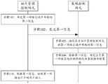
- Figure 1 is a schematic diagram in the prior art
- FIG. 2 is a schematic structural diagram of a communication system provided by an embodiment of the present application.
- FIG. 3 is a schematic diagram 1 of a 5G network architecture provided by an embodiment of this application.
- FIG. 4 is a schematic diagram 2 of a 5G network architecture provided by an embodiment of this application.
- FIG. 5 is a schematic structural diagram of a communication device according to an embodiment of this application.
- 6 to 12 are schematic flowcharts of the interaction between a transmission strategy determination method and a strategy control method provided by embodiments of the present application;
- FIG. 13 is a schematic flowchart of a user access control method according to an embodiment of the present application.
- FIG. 18 is a schematic structural diagram of a chip provided by an embodiment of the present application.
- the words “first” and “second” are used to distinguish the same items or similar items whose functions and functions are basically the same.
- the first information and the second information are only for distinguishing different information, and do not limit their order.
- the words “first” and “second” do not limit the number and execution order, and the words “first” and “second” do not necessarily mean different.
- the network architecture and business scenarios described in the embodiments of the present application are intended to more clearly explain the technical solutions of the embodiments of the present application, and do not constitute a limitation on the technical solutions provided by the embodiments of the present application. With the evolution of the architecture and the emergence of new business scenarios, the technical solutions provided in the embodiments of the present application are also applicable to similar technical problems.
- At least one refers to one or more, and “multiple” refers to two or more.
- “And/or” describes the relationship of the related objects, indicating that there can be three relationships, for example, A and/or B, which can mean: A exists alone, A and B exist at the same time, B exists alone, where A, B can be singular or plural.
- the character “/” generally indicates that the related object is a “or” relationship.
- “At least one of the following” or a similar expression refers to any combination of these items, including any combination of a single item or a plurality of items.
- At least one item (a) in a, b, or c can represent: a, b, c, ab, ac, bc, or abc, where a, b, c can be a single or multiple .
- FIG. 2 is a schematic diagram of a communication system provided by an embodiment of the present application.
- the communication system includes a slice management control network element 10 and a policy control network element 20 that communicates with the slice management control network element 10.
- the slice management and control network element 10 is used to determine the first information of the network in the first network area and to send the first information to the policy control network element 20.
- the first information includes: at least one of load information of the network in the first time period and load information of at least one network slice in the first time period, where the network includes at least one network slice.
- the policy control network element 20 is configured to receive the first information from the network in the first network area of the slice management control network element 10. And for determining the service data transmission strategy of the terminal located in the first network area according to the first information.
- An embodiment of the present application provides a communication system in which a policy control network element obtains load information of a network in a first network area in a first time period and load of at least one network slice in a first time period from a slice management control network element At least one of the information, and determine the service data transmission strategy of the terminal located in the first network area according to at least one of the load information of the network in the first time period and the load information of at least one network slice in the first time period . Since the load information of the network in the first period of time usually reflects whether the network is in an idle state, the load information of at least one network slice in the first period of time can be used to determine the load information of the network.
- the policy control network element can determine the service data transmission strategy of the terminal according to the network situation. On the one hand, it can avoid that the service data transmission of the terminal affects the operation quality of the network. On the other hand, the idle resources of the network can be fully utilized.
- the service data transmission strategy includes a second time period, where the second time period is a time period during which the load information of the network meets the preset network load requirements in the first time period.
- the policy control network element 20 is further used to determine the first time according to the load information of at least one network slice in the first time period The load information of the network in the segment.
- the policy control network element 20 is also used to send a first request to the slice management control network element 10, so that the slice management control network element 10 receives the first request.
- the first request is used to request the first information.
- the first request includes the second information, and the second information includes the identifier of the second network area, where the second network area includes the first network area.
- the communication system may further include a data analysis network element 30.
- the slice management control network element 10 is used to obtain third information from the data analysis network element 30, and the third information includes at least one of the following information corresponding to at least one network slice: identification information, time information, area information, and second The number of users, the second data volume, and service information.
- the service information is used to determine the status of the service in the network slice.
- the communication system shown in FIG. 2 can be applied to the current 5G network architecture and other network architectures that will appear in the future, which is not specifically limited in this embodiment of the present application.
- the following will take the communication system shown in FIG. 2 as an example for a 5G network architecture.
- slice management control network element 10 and the data analysis network element 30 may belong to the network element in the 5GC, and may also belong to the network management network element.
- the entity may be a network slice selection function (NSSF) network element in 5GC in the structure shown in FIG. 3.
- NSSF network slice selection function
- the slice management control network element 10 may also be a network slice selection function (NSMF) network element in the network management, a radio access network network slice subnet management function (radio access network, slice subnet management function, RAN-NSSMF) Network element, core network slice subnet management function (core-network slice subnet management function, CN-NSSMF) network element, transmission network network slice subnet management function (transfer network slice, subnet management function, TN-NSSMF) network element.
- NSMF network slice selection function
- the above policy control network element 20 may be a policy control function (PCF) network element in the non-roaming 5G network architecture.
- PCF policy control function
- the data analysis network element 30 may be a network data analysis function (NWDAF) network element in the 5GC, or a management data analysis function (Management Data Analysis Function, MDAF) network element, or even a RAN side Data analysis network element.
- NWDAAF network data analysis function
- MDAF Management Data Analysis Function
- the non-roaming 5G network architecture may further include: an access device (for example, an access network (AN) or a wireless access network (RAN)), a user plane Function (user plane function, UPF) network element, data network (DN), access and mobility management function (Access and Mobility Management Function, AMF) network element, authentication server function (AUSF) Network element, session management function (Session Management Function, SMF) network element, unified database (Unified Data Repository, UDR), unified data management (Unified Data Management, UDM), or binding support function (binding support function (BSF)).
- an access device for example, an access network (AN) or a wireless access network (RAN)
- a user plane Function user plane function, UPF
- data network data network
- AMF Access and Mobility Management Function
- AUSF authentication server function
- SMF Session Management Function
- UDR Unified Data Repository
- UDM Unified Data Management
- BSF binding support function
- NEF Network capability opening function
- NEF network warehouse storage function
- the terminal communicates with the AMF network element through a Next Generation (N1) interface (N1 for short).
- the access device communicates with the AMF network element through the N2 interface (N2 for short).
- the access device communicates with the UPF network element through the N3 interface (N3 for short).
- the UPF network element communicates with the DN through the N6 interface (N6 for short).
- the UPF network element communicates with the SMF network element through the N4 interface (N4 for short).
- the AMF network element communicates with the SMF network element through the N11 interface (N11 for short).
- the AMF network element communicates with the UDM network element through the N8 interface (N8 for short).
- the SMF network element communicates with the PCF network element through the N7 interface (N7 for short).
- the SMF network element communicates with the UDM network element through the N10 interface (N10 for short).
- the AMF network element communicates with the AUSF network element through the N12 interface (N12 for short).
- the AMF network element communicates with the NSSF network element through the N22 interface (N22 for short).
- the AUSF network element communicates with the UDM network element through the N13 interface (N13 for short).
- UDM network elements communicate with UDR network elements.
- PCF network elements communicate with UDR network elements
- BSF network elements communicate with PCF network elements and SMF network elements.
- the architecture based on a service interface in the non-roaming 5G network architecture is different from that in FIG. 3 in that the control plane network element in 5GC in FIG. 4 can also use a service interface to interact.
- AMF network elements, AUSF network elements, SMF network elements, UDM network elements, UDR network elements, NRF network elements, NEF network elements, NSSF network elements, or PCF network elements use service-based interfaces for interaction.
- the service interface provided by the AMF network element externally may be Namf.
- the service interface provided by the SMF network element to the outside may be Nsmf.
- the service interface provided by the UDM network element to the outside may be Nudm.
- the service interface provided by the UDR network element externally may be Nudr.
- the service interface provided by the PCF network element may be Npcf.
- the service interface provided by the BSF network element may be Nbsf.
- the service interface provided by the NEF network element may be Nnef.
- the service interface provided by the NRF network element may be Nnrf.
- the service interface provided by the NSSF network element may be Nnssf.
- the service interface provided by the NWDAF network element may be Nnwdaf.
- FIG. 3 and FIG. 4 are only an example of a PCF network element.
- the non-roaming 5G network architecture may include multiple PCF network elements, such as PCF network element 1 and PCF network element 2, which are not specifically limited in this embodiment of the present application.
- PCF network element 1 and PCF network element 2 are not specifically limited in this embodiment of the present application.
- a network element eg, slice management control network element 10 in the 5G core network (5GC)
- 5G core network 5G core network
- Each network slice may include one or more of UPF network elements, SMF network elements, NRF network elements, and PCF network elements.
- Some network functions can be shared among the multiple network slices.
- the collection of shared network functions can be referred to as common control network function (Common Control Network Function, CCNF).
- CCNF may include one or more of AMF network elements and NSSF network elements.
- Each network slice corresponds to at least one access device.
- One slice management control network element 10 can manage multiple AMF network elements, and the access device accesses the core network through the AMF network element, and one AMF network element can manage multiple access devices.
- network slicing refers to the physical or virtual network infrastructure, according to different service needs to customize different logical networks.
- Network slicing can be a complete end-to-end network including terminals, access networks, transmission networks, core networks and application servers. It can provide complete communication services and has certain network capabilities. Network slicing can guarantee the carrying of services or services.
- the communication resources that can meet the service level agreement (SLA) requirements can also be considered as a combination of network functions and communication resources required to complete a certain communication service or certain communication services.
- SLA service level agreement
- a network slice corresponds to a slice type and is identified by a single network slice selection support information (Single Network Selection Selection Assistance (S-NSSAI)).
- S-NSSAI Single Network Selection Selection Assistance
- a network slice can have multiple network slice instances (network slice instances, NSI), which are used to distinguish different tenants and different areas.
- NSI is a real logical network that can meet certain network characteristics or service needs.
- a complete network slice instance can provide complete end-to-end network services.
- the network slice instance can include one or more network slice subnet instances (NSSI) and one or more network functions (network functions, NF).
- NSSI network slice subnet instances
- NF network functions
- the access equipment in the embodiments of the present application may include RAN equipment, AN equipment, gNodeB equipment, eNodeB equipment, UMTS terrestrial radio access network (universal terrestrial radio access network, UTRAN) equipment, E-UTRAN (Evolved UTRAN, evolutionary UTRAN )device.
- RAN equipment AN equipment, gNodeB equipment, eNodeB equipment, UMTS terrestrial radio access network (universal terrestrial radio access network, UTRAN) equipment, E-UTRAN (Evolved UTRAN, evolutionary UTRAN )device.
- OAM network elements can cover the network elements of the access network and the core network, and data can be collected from these network elements of the access network and the core network.
- both the 3rd AF network element and the operator AF belong to the AF network element.
- 3rd AF network elements such as WeChat service server and Alipay payment service server
- operator AF network elements for example, the proxy-call session control function (proxy- in the IP multimedia system) call session control function (P-CSCF) network element
- P-CSCF proxy-call session control function
- the access device, AF network element, AMF network element, SMF network element, AUSF network element, UDM network element, UPF network element, and PCF network element of FIG. 3 or FIG. 4 are only one name.
- the device itself does not constitute a limitation.
- the network elements corresponding to the access device, AF network element, AMF network element, SMF network element, AUSF network element, UDM network element, UPF network element and PCF network element may also be other The name of this is not specifically limited in the embodiments of the present application.
- the UDM network element may also be replaced with a user home server (HSS) or a user subscription database (USD) or a database entity, etc., and will be described here in a unified manner, and will not be repeated hereafter. .
- HSS user home server
- USD user subscription database
- the terminals involved in the embodiments of the present application may include various handheld devices with wireless communication functions, vehicle-mounted devices, wearable devices, computing devices, or other processing devices connected to a wireless modem; or Including subscriber units, cellular phones, smart phones, wireless data cards, personal digital assistant (PDA) computers, tablet computers, wireless modems, handheld devices (handheld), laptop (laptop computer), cordless phone (cordless phone) or wireless local loop (wireless local loop (WLL) station, machine type communication (machine type communication (MTC) terminal, user equipment (user equipment) , UE), mobile station (mobile station, MS), terminal device (terminal device) or relay user equipment, etc.
- the relay user equipment may be, for example, a 5G residential gateway (RG).
- RG 5G residential gateway
- the access device involved in the embodiments of the present application refers to a device that accesses the core network, for example, it may be a base station, a broadband network service gateway (broadband network gateway, BNG), an aggregation switch, and non-third-generation cooperation 3rd Generation Partnership Project (3GPP) access equipment, etc.
- the base station may include various forms of base stations, such as macro base stations, micro base stations (also called small stations), relay stations, and access points.
- the network element eg, NSSF network element in the 5G core network (5G core network (5GC)
- the network element allocates one or more to the terminal Network slicing.
- Each network slice may include one or more of UPF network elements, SMF network elements, NRF network elements, and PCF network elements.
- each network element involved in the above FIG. 3 or FIG. 4 are as follows:
- the main functions of the UPF network element include: data packet routing and transmission, packet detection, service usage reporting, quality of service (QoS) processing, legal monitoring, upstream packet detection, and downstream data packet storage.
- QoS quality of service
- AMF network element the main functions include: connection management, mobility management, registration management, access authentication and authorization, accessibility management, or, security context management and other access and mobility related functions.
- the main functions include: session management (such as session establishment, modification and release, including the maintenance of tunnels between UPF network elements and AN equipment), selection and control of UPF network elements, service and session continuity (Service and Session Continuity) Continuity (SSC) mode selection, or, roaming and other session-related functions.
- session management such as session establishment, modification and release, including the maintenance of tunnels between UPF network elements and AN equipment
- selection and control of UPF network elements selection and control of UPF network elements
- service and session continuity Service and Session Continuity
- SSC Continuity
- the main functions of the PCF network element include: unified policy formulation, provision of policy control, and acquisition of policy decision-related contract information from UDR and other policy-related functions.
- NSSF network elements include: selecting a set of network slice instances for the terminal, or determining the allowed NSSAI and determining the set of AMF network elements that can serve the terminal, etc.
- NRF network elements include: service discovery function, maintenance of available NF text of Network Function (NF) instances and services supported by NF instances.
- the AF network element interacts with the 3GPP core network to provide services or services, including interacting with the NEF, or strategy architecture interaction.
- the main functions include: securely open the services and capabilities provided by the 3GPP network function, internally open, or open to third parties.
- UDM supports authentication credentials processing, user identity processing, access authorization, registration and mobility management, contract management, or short message management in 3GPP authentication and key negotiation mechanism.
- the AUSF network element interacts with UDM to obtain user information and performs authentication-related functions, such as generating intermediate keys.
- UDR is used to store subscribed data (Subscribed Data), policy information (Policy Data), application data (Application Data), etc.
- FIG. 5 is a schematic diagram of a hardware structure of a communication device provided by an embodiment of the present application.
- the communication device includes a processor 41, a communication line 44, and at least one communication interface (in FIG. 5, it is only exemplary to include the communication interface 43 as an example).
- the communication device may further include a memory 42.
- the processor 41 may be a general-purpose central processing unit (central processing unit, CPU), a microprocessor, an application-specific integrated circuit (ASIC), or one or more of which are used to control the execution of the program program of this application integrated circuit.
- CPU central processing unit
- ASIC application-specific integrated circuit
- the communication line 44 may include a path for transferring information between the aforementioned components.
- Communication interface 43 using any device such as a transceiver, for communicating with other devices or communication networks, such as Ethernet, wireless access network (RAN), wireless local area network (WLAN), etc. .
- RAN wireless access network
- WLAN wireless local area network
- the memory 42 may be a read-only memory (ROM) or other types of static storage devices that can store static information and instructions, random access memory (random access memory, RAM), or other types of information and instructions that can be stored
- the dynamic storage device can also be electrically erasable programmable read-only memory (electrically erasable programmable-read-only memory (EEPROM), read-only compact disc (compact disc read-only memory (CD-ROM) or other optical disc storage, optical disc storage (Including compact discs, laser discs, optical discs, digital versatile discs, Blu-ray discs, etc.), magnetic disk storage media or other magnetic storage devices, or can be used to carry or store desired program code in the form of instructions or data structures and can be used by a computer Access to any other media, but not limited to this.
- the memory may exist independently, and is connected to the processor through the communication line 44. The memory can also be integrated with the processor.
- the memory 42 is used to store computer execution instructions for executing the solution of the present application, and the processor 41 controls the execution.
- the processor 41 is used to execute computer execution instructions stored in the memory 42 to implement the policy control method provided in the following embodiments of the present application.
- the computer execution instructions in the embodiments of the present application may also be called application program codes, which are not specifically limited in the embodiments of the present application.
- the processor 41 may include one or more CPUs, such as CPU0 and CPU1 in FIG. 5.
- the communication device may include multiple processors, such as the processor 41 and the processor 45 in FIG. 5.
- processors can be a single-core (single-CPU) processor or a multi-core (multi-CPU) processor.
- the processor here may refer to one or more devices, circuits, and/or processing cores for processing data (eg, computer program instructions).
- An execution subject of a method for determining a transmission strategy in the embodiment of the present application may be a policy control network element, or may be a chip applied in the policy control network element.
- the execution subject of a policy control method may be a slice management control network element, or a chip applied in the slice management control network element.
- the execution subject of the policy control method is a slice management control network element
- the execution subject of a transmission strategy determination method is a policy control network element.
- FIG. 6 it is a schematic diagram of the interaction between a transmission strategy determination method and a strategy control method provided by the embodiment of the present application.
- the method includes the following steps:
- Step 101 The slice management control network element determines the first information of the network in the first network area.
- the first information includes: load information of the network in the first time period and/or load information of at least one network slice in the first time period.
- the network includes at least one network slice.
- the load information of the network in the first time period or the load information of at least one network slice in the first time period may help the policy control network element to generate the service data transmission strategy of the service in the at least one network slice, where the service data transmission strategy includes service data Transmission time information.
- the service data transmission time information is within the first time period.
- the service data transmission time information may be one or more of a time period (Time Interval), a time window (Time Window), or a time stamp (Timestamp).
- the first information includes load information of the network in the first time period.
- the first information includes load information of the network in the first time period and load information of at least one network slice in the first time period.
- the first information includes load information of at least one network slice in the first time period.
- the load information of at least one network slice in the first time period may be the load information of each network slice in the at least one network slice in the first time period.
- the load information of the network in the first time period is used to reflect the network status of the network in the first time period.
- the load information of the network may be at least one of the load level or the congestion level or the performance of the network.
- the load information of the at least one network slice may be load information or congestion level or performance of each network slice in the at least one network slice.
- the load information of any one of the at least one network slice is used to reflect the status of the any one network slice.
- the load information of the network slice may be at least one of the congestion level of the network slice, the load level (Slice Load Level) of the network slice, or the relationship between the quality and quality requirements of the network slice or the performance of the network slice.
- the relationship between the quality of the network slice and the quality requirements can be referred to as the satisfaction information of the network slice (Slice SLA fulfilment information).
- the values of different Slice Load levels can have the following meanings: 1. It means very light load. 2. Indicates light load. 3. It means normal. 4. Indicates congestion. 5. Expressing great congestion.
- the relationship between the quality of at least one network slice and the quality requirements of the network slice may be understood as: the relationship between the quality of each network slice in the at least one network slice and the quality requirements of the network slice. Since at least one network slice joins the same network, the operation quality of each other affects each other, so the quality of a network slice can generally be understood as: the degree to which the network where the network slice is located satisfies the SLA of the network slice.
- the quality of the network slice may be expressed as a percentage (for example, the degree of the network where the network slice is located meets the SLA of the network slice is 90%, that is, underfitting), and the quality requirement of the network slice is also expressed as a percentage Said. Therefore, the relationship between the quality of the network slice and the quality requirement of the network slice can be determined according to the size between the quality of the network slice and the quality requirement.
- the relationship between the quality of the network slice and the quality requirement of the network slice includes: the quality of the network slice is higher than the quality required by the quality requirement of the network slice.
- the Slice SLA fulfilment information is 120%, that is, the current network can meet the quality requirements of the slices by 120%, and it can also be understood that the network slices operate well in the network.
- the quality of the network slice is lower than the quality required by the quality requirements of the network slice.
- the slice SLA fullfilment information is 80%, that is, the current network can only meet the quality requirements of the slice 80%, which can also be understood as the network slice in the network The running quality is not good.
- the quality of the network slice is equal to the quality required by the quality requirement of the network slice.
- the Slice SLA fulfilment information is 100% or 99.99%, that is, the current network can meet the quality requirements of slicing 100% or 99.99%, and the network slicing quality in the network is good.
- the quality of the network slice is equal to the quality required by the quality requirement of the network slice, does not mean that the two are completely equal, as long as the two are close or the quality of the network slice does not fluctuate up or down to the quality requirement of the network slice Can be understood as equal.
- the first network area in the embodiment of the present application may include the network in step 101 or at least one network area where at least one network slice is located.
- the network area in the embodiment of the present application may be a tracking area (tacking area, TA), TA list, routing area (RA) or RA list, cell or cell list (cell list), or global positioning system location At least one of (GPS (Global Position System, physical area) or GPS list (GPS list)).
- the TA list includes at least one TA.
- the RA list includes at least one RA.
- the cell list includes at least one cell.
- the first network area may include TA1, TA2, and TA3.
- the network in step 101 is network 1 in TA1, network 2 in TA2, and network 3 in TA3.
- the first time period in the embodiment of the present application includes at least one time period.
- the load information of the network in the first time period may refer to the load information of the network in each time period in at least one time period.
- the load information of the at least one network slice in the first time period may be the load information of the network slice in each time period of the at least one time period.
- the first time period may be Timestamp or a time window.
- the first time period includes: 22:00 on November 20, 2018-08:00 on November 21, 2018, 22:00 on November 21, 2018-08:00 on November 22, 2018, 2018 From 22:00 on November 22 to 08:00 on November 23, 2018.
- Step 102 The slice management control network element sends the first information of the network in the first network area to the policy control network element.
- the slice management control network element when the slice management control network element sends to the policy control network element, it may also send the identifier of the network corresponding to the first information and the identifier of the first network area.
- step 102 may be specifically implemented in the following manner: the slice management control network element may send a network slice availability notification response service operation (Nnssf_NSSAIAvalability_Notify response) to the policy control network element, so that the policy control network element may respond from the network slice availability notification Get the first message.
- the network slice availability notification response carries the first information.
- Step 103 The policy control network element receives the first information from the network in the first network area of the slice management control network element.
- Step 104 The policy control network element determines the service data transmission policy of the terminal located in the first network area based on the first information.
- the policy control network element can determine whether the network is in an idle state or a non-idle state during the first time period by receiving load information from the network in the first time period from the slice management control network element.
- the policy control network element may determine to transmit the service data (eg, background traffic) of the terminal within the first time period. If the load level of the network or the congestion level of the network is greater than the first threshold in the first time period, it indicates that the load of the network is too high or the network is congested in the first time period, or the network is in a non-idle state during the first time period.
- the service data eg, background traffic
- the slice management control network element sends load information of at least one network slice in the first time period to the policy control network element.
- load level of any one network slice in the at least one network slice or the congestion level of any network slice in the first time period When it is less than or equal to the second threshold, it indicates that the load of any one network slice is lower than the second threshold or the any one network slice is not congested within the first time period. If the load level of any one network slice in at least one network slice or the congestion level of any one network slice in the first time period is greater than the second threshold, it indicates that the load of any one network slice in the first time period is too high or the Any one network slice is congested.
- the business data in the embodiment of the present application is background traffic (Background Data, BD), which may also be called background data.
- Background Data Background Data
- the background traffic refers to the traffic generated during the transmission of service data that is not required (or insensitive) for transmission timeliness.
- the background traffic refers to the traffic generated during the transmission of service data that has no requirements on the timeliness of transmission but has high (or sensitive) tariff requirements.
- there is no SLA requirement for the network slice used for background traffic transmission that is, as long as the network allows the transmission of background traffic, there is no transmission quality (such as transmission delay, transmission bandwidth) requirements. Therefore, background traffic can be transmitted when the network is idle.
- An embodiment of the present application provides a method for determining a transmission strategy.
- the policy control network element obtains, from the slice management control network element, load information of the network in the first network area in the first time period and/or at least one in the first time period.
- the load information of the network slice because the load information of the network in the first time period usually reflects whether the network is in an idle state.
- the load information of at least one network slice in the first time period may be used to determine the load information of the network. Therefore, the state of the network within the first time period can be obtained. If the network is in an idle state, it means that the network has idle resources at this time, that is, the network still has idle resources while satisfying the operation quality of at least one network slice.
- the policy control network element may determine the service data transmission strategy of the terminal according to the state of the network within the first time period. On the one hand, it can avoid that the service data transmission of the terminal affects the operation quality of at least one network slice in the network. On the other hand, the idle resources of the network can be fully utilized.
- the service data transmission strategy in the embodiment of the present application includes a second time period, where the second time period is a time period during which the load information of the network within the first time period meets the preset network load requirements .
- the terminal transmits service data in the second time period in the network, it does not affect the operation quality of at least one network slice in the network, and can also make full use of the idle resources of the network.
- the second time period is a time period during which the load level of the network in the first time period is less than or equal to the preset network load requirement.
- the second time period is a time period during which the network congestion level in the first time period is less than or equal to the preset network congestion requirement.
- the second time period is a time period in which the network congestion level is less than or equal to the preset network congestion requirement and the network load level is less than or equal to the preset network load requirement in the first time period. That is, the second time period is a time period during which the network can be in an idle state.
- the preset network load requirements and the preset network congestion requirements are not limited.
- the preset network load requirement and the preset network congestion requirement may be obtained from the AF network element by the policy control network element, or configured by the network management to the policy control network element.
- the second time period in the embodiments of the present application includes at least one time period.
- the at least one time period may be a continuous time period or a non-continuous time period, which is not limited in this embodiment of the present application.
- the method provided in this embodiment of the present application may further include: the policy control network element determines the second time period.
- the policy control network element determining the second time period may be implemented in any one of the following manner a or manner b:
- Manner a The policy control network element determines the second time period according to at least one of the load information of the network in the first time period and the load information of at least one network slice in the first time period.
- the first time period is T1-T5. If the network is in the idle state during the time period T1-T3, and the network is in the non-idle state during the time period T4-T5, the policy control network element may determine the second time period as the time period T1-T3.
- Manner b The policy control network element receives information from the slice management control network element indicating the second time period. The policy control network element determines the second time period according to the information indicating the second time period.
- the slice management control network element determines the second time period, and sends the information of the second time period to the policy control network element.
- the process of determining the second time period by the slice management control network element may refer to the process of determining the second time period by the policy control network element in manner a.
- the policy control network element in mode a may be replaced with a slice management control network element. I won't repeat them here.
- the information used to indicate the second time period may be the start time and duration of the second time period.
- the information for indicating the second time period may be the start time and the end time of the second time period, that is, the second time period.
- the method provided in this embodiment of the present application before step 104 further includes:
- Step 105 The policy control network element determines the load information of the network in the first time period according to the load information of at least one network slice in the first time period.
- the policy control network element determines that the load level or congestion level of any one of the at least one network slice in the first time period is less than or equal to the third threshold, it indicates the load of the network in the first time period The information is not congested or idle. Or, if the policy control network element determines that the load level or the congestion level of all or part of the network slices in at least one network slice in the first time period is less than or equal to the third threshold, it indicates the load information of the network in the first time period Not congested or idle.
- the policy control network element determines that there is a load level of one network slice in at least one network slice in the first time period or the congestion level of the network is greater than the third threshold, it indicates that the load information of the network in the first time period is congestion Or it is in a non-idle state. Or, if the policy control network element determines that the load level of all or part of the network slices or the network congestion level is greater than the third threshold in at least one network slice in the first time period, it indicates that the load information of the network in the first time period is congestion Or it is in a non-idle state.
- the process of the policy control network element determining the load information of the network in the first time period according to the load information of at least one network slice in the first time period belongs to the internal implementation of the policy control network element, and the above method is only an example.
- the policy control network element may also determine the first according to the load information of at least one network slice in the first time period and the local operator policy (for example, the logic of comparing the load level or congestion level of the network slice with the third threshold) Load information of the network during the time period.
- step 104 may be implemented in the following manner:
- the policy control network element determines the service data transmission strategy of the terminal located in the first network area according to the load information of the network in the first time period.
- the method provided in this embodiment of the present application further includes:
- Step 106 The policy control network element sends a first request to the slice management control network element, where the first request is used to request the first information.
- the first request includes second information, the second information includes an identifier of the second network area, and the second network area includes the first network area.
- the first request may be a network slice availability notification request (Nnssf_NSSAIAvalability_Notify request).
- the second network area is used by the slice management control network element to determine and obtain load information of the network in the specified network area or load information of at least one network slice.
- the first network area and the second network area may be the same, for example, if the second network area includes a TA list, the first network area may be at least one TA included in the TA list.
- the first network area may also be a subset of the second network area.
- the first network area may be a part of TAs in at least one TA included in the TA list, which is not limited in this embodiment of the present application.
- the method provided in the embodiment of the present application further includes: the policy control network element determines to perform step 101 according to the acquired service data transmission requirements.
- the service data transmission requirement is used to indicate the service data transmission strategy expected by the service providing server.
- the policy control network element may obtain the service data transmission requirements in the following manner: For example, the policy control network element receives the service data transmission requirements from the application function network element or the slice management control network element. For another example, the service data transmission requirements may be configured by the operator on the policy control network element.
- the network management network element sends the service data transmission requirements to the slice management control network element, or the operator configures the service data transmission requirements on the slice management control network element, and then the policy control network element obtains services from the slice management control network element Data transmission needs.
- the application function network element can be managed and controlled by the network slice tenant.
- the policy control network element may receive service data transmission requirements from the application function network element through the NEF network element.
- the content in the business data transmission requirements may be as shown in Table 1:
- the embodiment of the present application may further include: the slice management control network element determines the second network area.
- Example 1 if the service data transmission requirements carry information for determining the second network area, the policy control network element determines the second network area according to the information for determining the second network area.
- the information for determining the second network area may be the identification of the second network area, or the first indication information, which is used to determine the identification of the terminal located in the second network area (eg, terminal identification list ,
- the terminal identification list includes the identification of at least one terminal located in the second network area).
- the first indication information is the identification of the terminal located in the second network area, or the terminal group identification (UE group ID).
- the above example 1 may be implemented in any one of the following ways 1 or 2:
- Manner 1 If the service data transmission requirement carries the identifier of the second network area, the policy control network element determines the second network area according to the identifier of the second network area.
- the identifier of the network area in the embodiment of the present application may be a tracking area identification code (Tracking Area Identity, TAI), a TA list identifier, or any one of an RA identifier, an RA list identifier, or a cell identifier or a cell list identifier.
- TAI Tracking Area Identity
- TA list identifier any one of an RA identifier, an RA list identifier, or a cell identifier or a cell list identifier.
- the policy control network element determines the identity of the terminal located in the second network area according to the first indication information, and the policy control network element is located in the second network area
- the identifier of the terminal query the data analysis network element to obtain at least one network area corresponding to the identifier of the terminal located in the second network area. And determine the obtained at least one network area as the second network area.
- the terminal identifier in the embodiment of the present application may be one or more of the following: internet protocol address (internet protocol, IP), subscription permanent identifier (SUPI), permanent equipment identifier (permanent equipment identifier, PEI), generic public subscription identifier (GPSI), international mobile subscriber identifier (IMSI), international mobile equipment identifier (IMEI), IP quintuple (5- tuple) and mobile station international integrated service digital network number (MSISDN).
- IP internet protocol address
- SUPI subscription permanent identifier
- PEI permanent equipment identifier
- GPSI generic public subscription identifier
- IMSI international mobile subscriber identifier
- IMEI international mobile equipment identifier
- IP quintuple 5- tuple
- MSISDN mobile station international integrated service digital network number
- the policy control network element determines the identification of the terminal located in the second network area according to the first indication information, including: the policy control network element determines the terminal identification according to the terminal identification list At least one terminal indicated by the list. If the first indication information is the UE group ID, the policy control network element queries the UDM based on the UE group ID to obtain at least one terminal included in the terminal group, and then obtains a terminal identification list.
- the policy control network element may query the data analysis network element based on the ASP to obtain the terminal registered on the application function network element identified by the ASP ID The identifier list, and then query the data analysis network element based on the terminal identifier list to obtain the Network corresponding to the terminal identifier list, and determine the Network corresponding to the terminal identifier list as the second network area. Or the policy control network element directly queries the data analysis network element according to the ASP to obtain the Network corresponding to the terminal registered on the application function network element identified by the ASP ID.
- Step 107 The slice management control network element receives the first request from the policy control network element.
- step 101 may be implemented in the following manner: the slice management control network element determines the first information of the network in the first network area according to the first request.
- the second information described in step 106 may further include: information indicating the first time period.
- the slice management control network element can receive the second information from the policy control network element.
- the second information further includes service data transmission requirements.
- the service data transmission requirements are used to indicate the strategy that the service providing server expects to transmit the service data.
- the service data transmission requirements may include at least one of the following information: a third time period, the number of first users corresponding to the terminal, the amount of first data corresponding to the terminal, the identification of the terminal, and the service providing server serving the terminal The ID of the application function network element.
- the slice management and control network element can determine the network quality requirements of the network slice in which the user transmits the service according to the information in the service data transmission requirements.
- the terminal in the embodiment of the present application may refer to at least one terminal in the first network area.
- the third time period is used to indicate the service data transmission time of each terminal in at least one terminal expected by the service providing server.
- the first user number is used to indicate the number of terminals that the service providing server expects to transmit service data.
- the first data volume corresponding to the terminal may be the first data volume corresponding to at least one terminal in the first network area, that is, the size of the service data volume that at least one terminal needs to transmit.
- the identification of the terminal may be the identification of at least one terminal in the first network area.
- the service providing server serving the terminal may include a service server serving each of the at least one terminal.
- the third time period may include at least one time period.
- the third time period in the embodiment of the present application is the service data transmission time of the terminal expected by the service providing server
- the first time period is the network load information collected by the slice management control network element or the load information of at least one network slice Time period.
- the first time period may be a subset of the third time period, and the second time period may not overlap with the third time period, which is not limited in this embodiment of the present application.
- the method provided in this embodiment of the present application may further include:
- Step 108 The slice management control network element obtains the third information from the data analysis network element.
- the slice management control network element receives a data analysis information request response (Nnwdaf_AnalyticsInfo_Request response) from the data analysis network element.
- the data analysis information request response carries third information.
- the third information includes at least one of the following information corresponding to at least one network slice: identification information, time information, area information, second user number, second data volume, and service information.
- the service information is used to determine the status of the service in any network slice.
- the third information received by the slice management control network element from the data analysis network element is used to reflect the status of each network slice in at least one network slice in the current network.
- the number of second users in any network slice in the embodiment of the present application is used to represent the number of user accesses in any network slice.
- the second data volume in any one network slice of at least one network slice is used to represent the data volume in any one network slice.
- the service information includes a service ID (Application ID) corresponding to the service, and at least one of the following information: number of services, first average service experience, first service experience interval information, and first service satisfaction.
- the number of services is used to indicate the number of services that can be satisfied by the network where the network slice to which the service belongs is located.
- the service information may further include: a first maximum number of users (Maximum Users for the Application), which is used to indicate the maximum number of users of the service that can be satisfied by the network where the network slice to which the service belongs is located.
- a first maximum number of users Maximum Users for the Application
- the first average service experience (Average Service MOS) is used to represent the average service experience of the service that the current network can meet).
- the first service experience interval information (Service Range) is used to indicate the service experience interval of the service that the current network can satisfy.
- the first business satisfaction (HowmanypercentageUE’sexperienceshouldbesatisfied) is used to express the user satisfaction of the business that the current network can satisfy.
- the identification information of the network slice in the embodiment of the present application may be: S-NSSAI or Network Slice Selection Support Information (Network Slice Selection Assistance Information, NSSAI) or NSI ID.
- NSSAI Network Slice Selection Assistance Information
- the area information is used to indicate to the slice management control network element the network area that can support the network slice.
- the time information in the third information is used for the slice management control network element to determine the time period of the third information of the network slice.
- the time information may be a time window, a time stamp, and a time period.
- the time information in the third information is from March 1, 2018 to March 8, 2018.
- the slice management control network element can determine that the third information of the network slice is collected from March 1, 2018 to March 8, 2018.
- the slice management control network element may receive step 108 after receiving the first request from the policy control network element.
- the third information of a network slice includes: time information, area information, the first maximum number of users in the network slice, and service information of the network slice
- the third information of the network slice is used for slice management and control of the network element Determine the service information of the at least one service on the network slice in the specified area and the first maximum number of registered users in the specified time period.
- the third information of a network slice includes: time information, area information, and information of at least one service of the network slice
- the third information of the network slice is used by the slice management control network element to determine a specified area within a specified time period Service information of at least one service on the network slice.
- the method provided in this embodiment of the present application further includes: the slice management control network element sends a second request to the data analysis network element, so that the data analysis network element receives the second request from the slice management control network element request.
- the second request may be: a data analysis information request (Nnwdaf_AnalyticsInfo_Request).
- the second request is used to request third information.
- the second request includes an identification of the second network area and at least one of the following information of at least one network slice: identification information and time information.
- the slice management control network element may send a second request to the data analysis network element through the interface with the data analysis network element.
- the slice management control network element sends a second request to the data analysis network element to subscribe from the data analysis network element to the third information of at least one network slice in the second network area within the time period indicated by the time information (also possible It is called statistical information, namely estimated statistics.
- the embodiment of the present application does not limit the process of the data analysis network element acquiring the third information corresponding to each network slice in the at least one network slice, and reference may be made to the description in the prior art for details.
- the slice management control network element may also send a response indicating that the third information is received to the data analysis network element.
- the method provided in this embodiment of the present application may further include:
- Step 109 The slice management control network element obtains fourth information, where the fourth information includes at least one of the following information corresponding to at least one network slice: the number of third users and a list of terminal identifiers.
- the slice management control network element may determine the number of users existing in the at least one network slice according to the fourth information, that is, the number of users resident in the at least one network slice. It is used to help the slice management control network element determine the number of users that can be accommodated or allowed to be accessed in the network slice. Or it is convenient for the slice management and control network element to determine whether the network slice can still accommodate or allow user access.
- step 109 may specifically be implemented in the following manner: the slice management control network element sends a third request to the data analysis network element or at least one access and mobility management function network element serving the first network area , So that the data analysis network element or at least one access and mobility management function network element serving the first network area receives the third request from the slice management control network element.
- the slice management control network element receives the fourth information from the data analysis network element or at least one access and mobility management function network element.
- the third request is used to request fourth information, and the third request includes at least one of the following information of at least one network slice: identification information, time information, and area information;
- the slice management control network element may also send a response indicating that the fourth information is received to the data analysis network element or at least one access and mobility management function network element.
- an access and mobility management function network element usually includes multiple TAs, and a network area indicated by an area information can support multiple access Network elements for access and mobility management functions. Therefore, the slice management control network element can address at least one access and mobility management function network element supporting S-NSSAI under the TA through TA/S-NSSAI.
- step 101 in the embodiment of the present application may specifically be implemented in the following manner: slice The management control network element determines the first information according to at least one of the following information: second information, third information, and fourth information.
- the method provided in this embodiment of the present application further includes, before step 101, the slice management control network element obtains demand information, where the demand information is used to indicate the quality requirements of at least one network slice.
- the demand information may include: at least one of identification information of each network slice in the at least one network slice, a second maximum number of registered users, and service requirement information of at least one service.
- the service requirement information is used to indicate the tenant's requirement that the network can perform the service.
- the second maximum number of registered users represents the maximum number of registered users that a network slice is required to register. For example, 10million.
- the demand information may further include: at least one of area information and time information.
- the demand information may also include bandwidth requirements, delay requirements, and so on.
- the application function network element sends the demand information to the slice management control network element through the policy control network element, that is, the slice management control network element obtains the demand information from the application function network element controlled by the tenant through the policy control network element.
- the demand information may be configured by the operator on the slice management control network element.
- the demand information may be sent by the network management network element to the slice management control network element.
- the application function network element can be managed by the slice tenant.
- the service requirement information includes: Application ID, the second maximum number of users (Required Maximum Users for the Application, that is, the maximum number of users of the service that the tenant requires the network to meet), and the second average service experience (Required Average Service MOS , That is, the average service experience of the service that the tenant requires the network to meet), the second service experience interval information (Requested Service MOS range, that is, the service experience interval of the service that the tenant requires the network to meet), and the second service satisfaction ( How many people UE's experience should be satisfied, that is, at least one of the user satisfaction of the service that the tenant requires that the network can meet.
- Application ID the second maximum number of users
- Required Average Service MOS That is, the average service experience of the service that the tenant requires the network to meet
- the second service experience interval information that is, the service experience interval of the service that the tenant requires the network to meet
- the second service satisfaction How many people UE's experience should be satisfied, that is, at least one of the user satisfaction of the service that the tenant requires that
- the second maximum number of users represents the maximum number of users in a service, that is, the total number of services using a certain service. For example, 10000.
- the service identifier is used to identify the service in the slice.
- the second service experience interval information is used to indicate service experience requirements in the service.
- the service in the network slice may be a voice service as an example, and the range of the second MOS is [0.0, 5.0].
- the MOS score is greater than or equal to 3.0
- the MOS may be increased according to the good degree, and the MOS may be 4.0, 4.5, 5.0, and so on.
- the higher the MOS value the stricter the QoS parameter requirements for the corresponding voice service, and the higher the network quality requirements.
- the higher the network resource requirements the higher the network slice resource requirements.
- the second service satisfaction is used to indicate the proportion of the total number of services required by the service tenant to satisfy the second service experience interval information in the service.
- the ratio is a first threshold, that is, the ratio of the number of services required by the tenant to satisfy the second service experience interval information to the total number of services in the service is greater than or equal to the first threshold.
- the embodiment of the present application does not limit the first threshold.
- tenants usually put forward business satisfaction requirements to operators.
- MOS the proportion of services requiring MOS greater than or equal to 3.0 to the total number of services is greater than or equal to 95%.
- the slice management control network element determines the first information according to at least one of the second information, the third information, and the fourth information, which may be implemented in the following manner:
- a network slice has only one service, and the tenant requires a service experience (that is, Service MOS) higher than 4.0, and requires more than 95% user service satisfaction.
- service MOS Service MOS
- the quality and quality requirements of the network slice are as follows:
- the slice management control network element determines that the network can meet the quality requirements of the network slice by 120%, that is, the service MOS in the third information of the network slice is 4.8, and 98% of the user's service satisfaction.
- the quality corresponding to the network slice is higher than the quality required by the network slice quality requirements, which can be referred to as overfitting.
- the slicing management and control network element determines that the network can meet the quality requirements of network slicing 80%, that is, the service MOS in the third information of the network slicing is 3.2, and 76% of the users have business satisfaction.
- the quality corresponding to the network slice is lower than the quality required by the network slice quality requirements, which can be called underfitting.
- the slice management control network element obtains a network slice from a third area in a network area corresponding to the number of users of the network slice required by a tenant or service provider within a time period, and obtains the network from the fourth information The number of users residing in the network area corresponding to the time period in the slice. If the number of users of the network slice required by the tenant or service provider is greater than the number of users residing in the network slice within the time period, the slice management control network element may consider the quality corresponding to the network slice to be higher than the quality corresponding to the network slice
- the quality required by the network slice can be called overfitting, which means that more users can be allowed in the network slice, that is, the load information of the network slice is not congested or idle. Conversely, it can be determined that the quality corresponding to the network slice is lower than the quality required by the network slice.
- the above embodiment is only one of the methods for determining the relationship between the quality of network slices and the quality requirements of network slices, which is a more complex scenario, for example, when there are multiple services in multiple network slices It is necessary to design more complex algorithms, which belong to the internal product realization of the data analysis network element. Then, during the actual operation, the introduction of a new network slice or a network slice without an SLA may have an impact on the running quality of the existing network slice. Therefore, between determining the quality of a network slice and the quality requirements of the network slice In addition to the third information of the network slice itself, optionally, the third information of other network slices should be referred to.
- step 101 may be specifically implemented in the following manner: the slice management control network element determines the quality of each network slice corresponding to each network slice according to the third information corresponding to each network slice in the at least one network slice and a pre-configuration strategy And the quality requirements of network slicing.
- the pre-configuration strategy may be a requirement for the maximum number of registered users in the network slice.
- the relationship between the quality of the network slice of the network slice and the quality requirements of the network slice consider the current maximum number of registered users in the network that can satisfy the network slice and the second maximum number of registered users in the network slice The size relationship between requirements.
- the size relationship can be higher, lower, equal, or close.
- the slice management control network element determines the relationship between the quality of the network slice corresponding to NS1 and the quality requirement of the network slice according to the third information corresponding to NS1 and the pre-configuration strategy.
- the slice management control network element determines the relationship between the quality of the network slice corresponding to NS2 and the quality requirement of the network slice according to the third information corresponding to NS2 and the pre-configuration strategy.
- the slice management control network element determines the relationship between the quality of the network slice corresponding to NS3 and the quality requirement of the network slice according to the third information corresponding to NS3 and the pre-configuration strategy.
- the method provided in this embodiment of the present application may further include:
- Step 110 The slice management control network element controls user access in the first network slice according to at least one of the first information, the second information, the third information, and the fourth information.
- controlling the user access in a network slice in the embodiments of the present application refers to controlling the number of users or terminals in the network slice. Or the number of services of one service accessed in the network slice.
- first network slice in step 110 and at least one network slice in step 101 are network slices in the same network area.
- first network slice in step 110 and at least one network slice in step 101 are network slices in the same time period in the same network area.
- the at least one network slice may or may not include the first network slice.
- step 110 in the embodiment of the present application may specifically be implemented by any one of the following examples 1 to 3:
- Example 1 The slice management control network element determines that the quality of the first network slice is higher than the quality requirement of the first network slice, and the slice management control network element reduces user access in the first network slice.
- the relationship between the quality of the first network slice and the quality requirement of the first network slice may be determined by the quality of at least one network slice and the quality of at least one network slice Ask for confirmation. That is, the load information of at least one network slice determines the time period during which background traffic can be transmitted.
- the slice management control network element determines that the quality of the first network slice is higher than the quality requirement of the first network slice, including: the slice management control network element determines that there is any network slice in the at least one network slice except the first network slice Is less than the quality requirement of any network slice, and the slice management control network element determines that the quality of the first network slice is higher than the quality requirement of the first network slice.
- the specific slice management controls how the network element determines the relationship between the quality of the first network slice and the quality requirements of the first network slice, referring to the prior art.
- At least one network slice includes: NS1, NS2, and NS3.
- the first network slice is NS1. If the slice management control network element determines that the quality of NS2 is less than the quality requirement of NS2, the slice management control network element determines that the quality of NS1 is higher than the quality requirement of the first network slice.
- the slice management control network element determines that the quality of the first network slice is higher than the quality requirement of the first network slice, including: the slice management control network element according to the first network slice The first information determines the quality of the first network slice.
- the slice management control network element determines that the quality of the first network slice is higher than the quality requirement of the first network slice.
- the slice management control network element determines that the quality of the first network slice is higher than the quality requirement of the first network slice, including: the slice management control network element according to the at least one network slice
- the first information determines the quality of at least one network slice.
- the slice management control network element determines that the quality of the first network slice is higher than the quality requirement of the first network slice.
- the method provided in this embodiment of the present application further includes: the slice management control network element sends the relationship between the quality and quality requirements of at least one network slice to the access device.
- the slice management control network element sends information that the quality of the first network slice is higher than the quality requirement of the first network slice to the access device, so that the access device can reduce resources allocated to the first network slice.
- the slice management control network element sends the information that the quality of the remaining network slices in at least one network slice other than the first network slice is lower than or equal to the quality requirements of the remaining network slices to the access device, so that the access The device can increase the resources allocated for the remaining network slices.
- the slice management control network element determines that the quality of any one network slice except the first network slice in at least one network slice is higher than the quality requirement of any one network slice, and the slice management control network element increases users in the first network slice Access.
- Example 2 may specifically be implemented in the following manner: in a case where the quality of any one network slice other than the first network slice in at least one network slice is higher than the quality requirement of any one network slice , The slice management control network element determines that the current number of user accesses in the first network slice is less than the second maximum number of registered users, and the slice management control network element increases the number of user accesses in the first network slice.
- the slice management control network element determines the current network slice in the first network slice The number of user accesses is less than the second maximum number of registered users equal to the second maximum number of registered users, and the slice management control network element sends the relationship between the quality and quality requirements of at least one network slice to the access device.
- the terminals in the first network area are served by the first network slice.
- the first network slice is used to transmit background traffic.
- the policy control network element first provides service data transmission requirements, namely TA1, to the slice management control network element.
- the service data transmission requirements may also include: ASP, number of terminals (number of UEs), the first data amount of the terminal, and time window.
- the slice management control network element first obtains the statistical information of network slice 1 and network slice 2 in different time windows under TA1 (that is, the network slice 1, network slice 2 runs in the network) and the network slice configured on the slice management control network element 1.
- the quality requirements of network slice 2 determine the slice SLA fulfilment information of network slice 1, network slice 2, and then feedback the slice SLA fulfilment information to the policy control network element.
- the policy control network element found through the slice information of network slice 1 and network slice 2 that the slice SLA is overfitting in the time period from 00:00 to 01:00 under TA1, that is, the network is idle during this time period Resources can be used to transmit background traffic.
- the policy control network element uses 00:00-01:00 as the background traffic transmission strategy and sends it to the AF network element.
- the policy control network element determines that the relationship between the quality and quality requirements of the network slice 1 and network slice 2 exceeds 100%, and queries the AMF to determine that the current BDT slice in TA 1 has 30,000 users, and the network slice The quality requirement of the BDT requires that the number of users in the BDT slice is 100,000. Therefore, the policy control network element determines that the BDT slice can access more users.
- the communication system shown in FIG. 2 is applied to the 5G network shown in FIG. 3, the policy control network element is a PCF network element, the slice management control network element is an NSSF network element, and the data analysis network element is a NWDAF network element 5.
- the 5G network also includes: AMF network element, AF network element, NEF network element, and RAN equipment. Taking service data as background traffic as an example, as shown in FIG. 11, it is a transmission strategy determination method provided by an embodiment of the present application. And strategy control method, the method includes the following steps:
- Step 201 The AF network element sends a background data transmission strategy negotiation establishment (Nnef_BDTPNegotiation_Create) service request to the NEF network element, so that the NEF receives the background data transmission strategy negotiation establishment service request from the AF network element.
- the AF network element that establishes a service request through background data transmission strategy negotiation can request the background traffic transmission strategy from the network side.
- the background data transmission strategy negotiation establishment service request carries business data transmission requirements.
- the content of service data transmission requirements is shown in Table 1, and will not be repeated here.
- Step 202 The NEF network element sends a background data transmission policy control establishment (Npcf_BDTPolicyControl_Create) service request to the PCF network element, so that the PCF network element receives the background data transmission policy control establishment service request from the NEF.
- Npcf_BDTPolicyControl_Create a background data transmission policy control establishment
- the background data transmission policy control establishment service request carries business data transmission requirements from the AF network element.
- Step 203 The PCF network element sends a network slice availability notification request to the NSSF network element, so that the NSSF network element receives the network slice availability notification request from the PCF network element.
- the network slice availability notification request carries the identifier of the second network area.
- the network slice availability notification request may also carry: a third time period, the number of first users corresponding to the terminal, the first amount of data corresponding to the terminal, the identification of the terminal, and application functions corresponding to the service providing server serving the terminal.
- the identifier of the network element ASP identifier, ASP ID.
- the slice management and control network element can determine the network quality requirements of the network slice in which the user transmits the service according to the information in the service data transmission requirements.
- Step 204 The NSSF network element sends a data analysis information request to the NWDAF network element, so that the NWDAF network element receives the data analysis information request.
- the data analysis information request carries identification information of at least one network slice. It should be understood that at least one network slice is a network slice included in the network in the second network area.
- Step 205 The NWDAF network element sends a data analysis information request response to the NSSF network element, so that the NWDAF network element receives the data analysis information request response.
- the data analysis information request response carries the quality of each network slice in at least one network slice in the first network area.
- Step 206 The NSSF network element sends a network slice availability notification request response to the PCF network element, where the network slice availability notification request response carries the quality of each network slice.
- Step 207 The PCF network element determines the relationship between the quality of each network slice in different time periods and the respective quality requirements based on the quality of each network slice in at least one network slice in different time periods in the first network area.
- Step 208 The PCF network element determines the background traffic transmission strategy according to the relationship between the quality of each network slice and the respective quality requirements in different time periods.
- the PCF network element may determine the time period when the quality of the network slice is higher than the quality requirement as the background traffic transmission strategy according to the relationship between the quality of each network slice and the respective quality requirements in different time periods.
- Step 209 The PCF network element sends a background flow policy control establishment response (Npcf_BDTPolicyControl_Create response) to the NEF network element.
- the background traffic policy control establishment response carries the background traffic transmission policy.
- Step 210 The NEF network element sends a background traffic negotiation establishment response (Nnef_BDTPNegotiation_Create response) to the AF network element.
- Nnef_BDTPNegotiation_Create response a background traffic negotiation establishment response
- the background traffic negotiation establishment response carries the background traffic transmission strategy.
- At least one network slice in steps 201-210 does not include a background traffic slice (BDT slice).
- BDT slice background traffic slice
- Step 211 The NSSF network element sends a data analysis information request to the NWDAF network element, so as to obtain statistical information of the BDT slice in different time periods under the first network area from the NWDAF network element.
- the data analysis information request carries the identifier of the first network area and the identifier information of the BDT slice.
- Step 212 The NSSF network element receives the data analysis information request response from the NWDAF network element.
- the data analysis information request response carries satisfaction information (Statistics Infofmation) of the BDT slice in the first network area.
- the satisfaction information of the BDT slice includes: identification information of the BDT slice, network area, background traffic size (may be terminal level) that has been transmitted in the BDT slice, and number of terminals that have transmitted background traffic.
- Step 213 The NSSF network element sends the identification of the first network area and the identification information of the BDT slice to at least one AMF network element.
- Step 214 The NSSF network element receives a network slice validity update service operation (Nnssf_NSSAIAvailability_Update) from at least one AMF network element.
- Nnssf_NSSAIAvailability_Update a network slice validity update service operation
- the NSSF network element determines in step 206 that the quality of at least one network slice is less than the quality requirement (that is, the Slice SLA fulfilment information is underfitting)
- the NSSF network element performs the following step 215. Or perform step 215 and step 216.
- step 206 If the NSSF network element determines in step 206 that the quality of any one network slice in at least one network slice is higher than the quality requirement of the any network slice (ie, any network slice is overfitted), then step 217 or step 218 is performed.
- Step 215 The NSSF network element determines that the slice SLA fullfilment information of the BDT slice is overfitting, and then the NSSF reduces the number of registered users in the BDT slice.
- Step 216 The NSSF network element sends the slice SLA fulfilment information of at least one network slice and/or the slice SLA fulfilment information of the BDT slice to the RAN.
- the RAN may decide the resource scheduling after receiving the slice SLA fulfilment information of at least one network slice and/or the slice SLA fulfilment information of the BDT slice. For example, increase or decrease the air interface resource scheduling of BDT slices.
- the NSSF network element sends a network slice availability notification to at least one AMF network element corresponding to the RAN, where the network slice availability notification carries Slice information of at least one network slice in the first network area and/or Slice of BDT slice SLAfulfilment information. Then at least one AMF network element sends the slice information of the at least one network slice and/or the slice information of the BDT slice to the RAN through the configuration information update confirmation information (CONFIGURATION UPDATE ACKNOWLEDGE).
- the configuration information update confirmation information CONFIGURATION UPDATE ACKNOWLEDGE
- the air interface resource scheduling of the BDT slice is increased.
- Step 217 If the NSSF network element determines that the number of terminals in the service data transmission requirement is greater than the number of terminals that have transmitted background traffic in step 212, the NSSF network element allows more users to access the BDT slice.
- any network slice is overfitted, and the number of first users corresponding to the terminal in step 203 is greater than the number of terminals that have transmitted background traffic in step 212, that is, any network slice belongs to sufficient network resources, the BDT slice You can also allow users to join.
- Step 218 If the NSSF network element determines that the number of terminals in the service data transmission requirement is equal to the number of terminals in the background traffic that has been transmitted in step 212, the NSSF network element sends to the RAN Slice information of at least one network slice and/or BDT slice The SLA fulfilment information.
- the NSSF network element determines that the number of terminals in the background traffic transmission requirement is equal to the number of terminals in the background traffic that have been transmitted in step 212, that is, although the current network resources are sufficient, the number of users required by the tenant has all been added to the background traffic slice. In this case, the NSSF network element believes that the Slice, SLA, and fulfilment information of the BDT slice is overfitting, and the air interface resources allocated to the BDT slice increase.
- the RAN may decide to reduce the air interface resource scheduling of the BDT slice.
- the NSSF network element also needs to refer to the statistics information of the BDT slice from the NWDAF network element when deciding the slice SLA fulfilment information of the BDT slice. For example, only when the NSSF network element finds that the number of terminals required for service data transmission in step 203 is equal to the sum of the number of terminals with background traffic already transmitted in step 212 and the number of currently registered users in the background traffic slice, will RAN be further notified Reduce the air interface resources allocated for BDT slices.
- the NSSF network element can control the number of users in the BDT slice to avoid affecting the operation quality of at least one network slice.
- FIG. 12 shows another transmission strategy determination method and strategy control method.
- the method includes:
- Steps 301 to 305 are the same as steps 201 to 205 in the embodiment shown in FIG. 11. For related description, reference may be made to the embodiment shown in FIG. 11, which will not be repeated here.
- step 306 determines that the background traffic transmission strategy includes the second time period through the Slice SLA fulfilment information of at least one network slice.
- Step 307 The NSSF network element sends a network slice availability notification request response to the PCF network element.
- the network slice availability notification request response carries the background traffic transmission strategy.
- Steps 308 to 317 are the same as steps 209 to 218 in the embodiment shown in FIG. 11. For related description, reference may be made to the embodiment shown in FIG. 11, which is not repeated here.
- FIG. 13 shows a user access control method provided by an embodiment of the present application.
- This method can do information on network slice requirements of tenants or service providers, such as network area and number of users.
- Split generate at least one network sub-region and the number of users required by tenants or service providers in each network sub-region, and then feed back to the NSSF network element to help the NSSF network element to control the number of sliced users more finely and accurately.
- Step 401 The first network element determines the first information of the first network slice in the first network area.
- the first network element determines that the first information of the first network slice in the first network area should be in the early stage of slice deployment or the network management newly creates the first network slice.
- the process of determining the first network slice in the first network area by the first network slice is a process in which the first network element divides the slice requirements of the first network slice, or the first network element is obtained from another network element
- the slicing of the first network slice requires the process of segmenting the results.
- the first information includes at least one of the number of first users, the number of second users, and the number of third users.
- the first user number is used to indicate the number of users expected or required in the first network slice in the first network area
- the second user number is used to indicate the number of users connected to the first network slice in the first network area
- the number of third users is used to indicate the number of users allowed to be accessed by the first network slice in the first network area.
- the slice management control management network element controls user access in the first network slice according to the first information. It should be understood that the number of third users is the number of users allowed to be accessed by the first network slice in the first network area determined by the first network element or obtained from other network elements. It can be further understood that the number of third users is the initial number of users allowed to be accessed before the first network slice in the first network area before the drive test or at the initial stage of creation or before signing the SLA.
- the number of first users is the number of users required to register for the first network slice in the first network area.
- the number of first users is the number of users of the first network slice in the first network area expected or required by the service server or service provider corresponding to the first network slice. For example, 100,000.
- the number of second users is 80,000.
- the third user number is the maximum number of users allowed by the network to be accessed by the first network slice in the first network area. For example, 120,000.
- Step 402 The first network element sends the first information of the first network slice in the first network area to the slice management control management network element.
- the first information of the first network slice in the first network area may further include at least one of the following information: identification information of the first network slice, identification of the first network area, and first time information At least one service information, wherein the service information includes at least one of the following information: service identifier, first service number, first average service experience, and first user satisfaction.
- the first time information is time information corresponding to the first network slice in the first network area.
- the first service number is used to indicate the number of users using the service in the first network slice in the first network area
- the first user satisfaction is the number of users using the service in the first network slice in the first network area The proportion of users who meet the business experience requirements.
- time information in the embodiment of the present application may specifically correspond to any one of a time period, a time window, and a time stamp.
- Step 403 The slice management control network element receives the first information of the first network slice in the first network area from the first network element.
- the slice management control network element in the embodiment of the present application may be any one of NSSF network element, AMF network element or PCF network element.
- Step 404 The slice management control management network element controls user access in the first network slice according to the first information.
- the slice management control network element may determine the number of users (the number of first users) required by the tenant or service provider of the first network slice in the first network area and the resident in the first network slice based on the first information Number of users (number of second users), number of users allowed in the first network slice (number of (initial) third users). Further, the slice management network element may gradually add new users to the first network slice according to the number of third users, that is, increase the number of third users.
- the slice management network element finds that the quality of all or part of the network slices in at least one network slice is higher than the quality requirements, and the number of first users is greater than the number of second users, it means that the current first network slice has not affected other networks in the network If the running quality of the slice, the slice management network element may allow more users to access the first network slice, that is, increase the number of third users.
- the slice management network element finds that all or part of the quality of at least one network slice is higher than the quality requirement, and the number of first users is equal to the number of second users, it means that the current first network slice fails to run quality of other network slices in the network , And all users are required to be satisfied.
- the slice control network element finds that as long as the quality of at least one network slice is lower than the quality requirement of the network slice in at least one network slice, it means that the first network slice affects the operation quality of other network slices in the network, and the first network needs to be reduced The number of users in the slice.
- the first network element may be a policy control network element or a data analysis network element or a network management network element or an access and mobility management function network element.
- step 401 may be specifically implemented in the following manner: the policy control network element receives the first information from the data analysis network element or the network management network element.
- the policy control network element receives the first information from the data analysis network element or the network management network element, including: the policy control network element sends a first request to the data analysis network element or the network management network element, and the first request is used to request the first Information, the first request includes second information, and the second information includes at least one of the following information: identification information of the first network slice, second network area, terminal group identification, terminal identification of at least one terminal, the number of fourth users, The identification of the application function network element and at least one service requirement information.
- the first network slice serves the second network area, the second network area includes the first network area, the second network area is a network area where at least one terminal corresponding to the application function network element is located, and the terminal group identifier corresponds to at least one terminal ,
- the third user number is the number of users corresponding to at least one terminal.
- the policy control network element receives the first response from the data analysis network element or the network management network element, and the first response includes the first information.
- the service requirement information includes at least one of the following information: service identifier, second service number, second average service experience, second service experience interval information, and second service satisfaction.
- the second service number is the number of users using the service expected or required by the service server or service provider corresponding to the first network slice
- the second service experience is provided by the service server or service corresponding to the first network slice
- the service experience of the service that is expected or required by the party, and the second service experience interval information is the service experience interval of the service that the service server or service provider corresponding to the first network slice expects or requires
- the second service Satisfaction is the service satisfaction of the service expected or required by the service server or service provider corresponding to the first network slice.
- the method provided in this embodiment of the present application further includes: the policy control network element obtains the second information from the application function network element or the network management network element.
- the tenant or service provider of the first network slice can configure the second information on the policy control network element through the operator, so that the policy control network element can obtain the second information locally.
- the policy control network element may query the database network element according to the terminal group identifier or the application function network element identifier in the second information to obtain at least one terminal's Terminal identification.
- the database network element may be UDM or UDR.
- the data analysis network element determining the first information includes: the data analysis network element is obtained from the policy control function network element or the application function network element or the network management network element Second information; the data analysis network element determines the first information according to the second information.
- the method provided in this embodiment of the present application further includes: the data analysis network element sends the third information of at least one network slice in the first network area to the slice management control network element.
- the third information of any one of the at least one network slice includes at least one of the following information: identification information of the network slice, third time information, identification of the third network area, number of fifth users, at least one service Information.
- the fifth user number is used to indicate the number of users accessed in any one network slice
- the service information is used to determine the status of the service.
- the service information includes at least one of the following information corresponding to the service: service identifier, third service number, third average service experience, third service experience interval information, third service satisfaction, and third service number Indicate the number of users using the service in the network slice to which the service belongs.
- the method provided in this embodiment of the present application further includes: the slice management control network element receives third information of at least one network slice in the first network area from the data analysis network element or the network management network element.
- the third time information may be the first time information, or may be sub-time information in the first time information, or may be other time information.
- step 404 may be specifically implemented in the following manner: the slice management control management network element controls user access of the first network slice according to the first information and the third information of the at least one network slice.
- At least one network slice includes a first network slice, so that the slice management control network element can control the user of the first network slice according to the third information of the first network slice and the first information of the first network slice Access.
- the method provided in this embodiment of the present application further includes:
- Step 405 The slice management control network element sends the first network element fourth information of the first network slice in the first network area.
- the fourth information includes the sixth user number, and the sixth user number is used to indicate the first network area.
- the first network element receives the fourth information of the first network slice in the first network area, and sends the fourth information of the first network slice in the first network area to the AF network element or the OAM network element.
- the first network slice is a network slice that transmits background traffic.
- each network element such as a transmission strategy determination device (for example, a slice management control network element), a policy control device (for example, a policy control network element), etc.
- a transmission strategy determination device for example, a slice management control network element
- a policy control device for example, a policy control network element
- each network element includes hardware corresponding to each function Structure and/or software module.
- the present application can be implemented in the form of hardware or a combination of hardware and computer software. Whether a function is executed by hardware or computer software driven hardware depends on the specific application and design constraints of the technical solution. Professional technicians can use different methods to implement the described functions for each specific application, but such implementation should not be considered beyond the scope of this application.
- the embodiments of the present application may divide the functional unit according to the above method example transmission strategy determination device and strategy control device, for example, each functional unit may be divided corresponding to each function, or two or more functions may be integrated into one processing unit in.
- the above integrated unit may be implemented in the form of hardware or software functional unit. It should be noted that the division of the units in the embodiments of the present application is schematic, and is only a division of logical functions. In actual implementation, there may be another division manner.
- FIG. 14 shows a communication device involved in the foregoing embodiment.
- the communication device may include a receiving unit 101 and a processing unit 102.
- the transmission strategy determination device may be a policy control network element or a chip applied in the policy control network element.
- the receiving unit 101 is configured to support the transmission strategy determination device to perform step 103 in the foregoing embodiment.
- the processing unit 102 is configured to support the transmission strategy determination device to perform step 104 in the foregoing embodiment.
- the processing unit 102 is also used to support the transmission strategy determination apparatus to perform step 105 in the foregoing embodiment.
- the transmission strategy determination device provided in this embodiment of the present application further includes: a sending unit 103, which is also used to support the transmission strategy determination device to perform step 106 in the foregoing embodiment.
- the device for user access control may be a slice management control management network element.
- the receiving unit 101, the device for supporting the user access control executes step 403 and step 405 in the foregoing embodiment.
- the processing unit 102 is a device for supporting user access control to execute step 404 in the foregoing embodiment.
- FIG. 15 shows a schematic diagram of a possible logical structure of the communication device involved in the foregoing embodiment.
- the communication device includes a processing module 112 and a communication module 113.
- the processing module 112 is used to control and manage the operation of the communication device.
- the processing module 112 is used to execute information/data processing steps on the communication device.
- the communication module 113 is used to support the steps of transmitting or receiving information/data from the communication device.
- the communication device may further include a storage module 111 for storing program codes and data that the communication device can use.
- the transmission strategy determination device may be a policy control network element or a chip applied in the policy control network element.
- the communication module 113 is used to support the transmission strategy determination device to perform step 103 in the above embodiment.
- the processing module 112 is configured to support the transmission strategy determination apparatus to perform step 104 in the foregoing embodiment.
- processing module 112 is also used to support the transmission strategy determination apparatus to perform steps 109 and 105 in the foregoing embodiment.
- the communication module 113 is also used to support the transmission strategy determination apparatus to perform step 106 in the foregoing embodiment.
- the user access control device may be a slice management control management network element.
- the communication module 113 the device for supporting the user access control executes step 403 and step 405 in the foregoing embodiment.
- the processing module 112 is configured to support a user access control device to perform step 404 in the foregoing embodiment.
- the processing module 112 may be a processor or a controller, for example, it may be a central processor unit, a general-purpose processor, a digital signal processor, an application specific integrated circuit, a field programmable gate array or other programmable logic devices, transistor logic devices, Hardware components or any combination thereof. It can implement or execute various exemplary logical blocks, modules and circuits described in conjunction with the disclosure of the present invention.
- the processor may also be a combination of computing functions, for example, including one or more microprocessor combinations, a combination of a digital signal processor and a microprocessor, and so on.
- the communication module 113 may be a transceiver, a transceiver circuit, a communication interface, or the like.
- the storage module 111 may be a memory.
- the processing module 112 is the processor 41 or the processor 45
- the communication module 113 is the communication interface 43 or the transceiver
- the storage module 111 is the memory 42
- the user access control device involved in this application may be as shown in FIG. 5 communication device.
- the memory 42, the processor 41 or the processor 45 and the communication interface 43 are connected to each other through a communication line 44.
- the communication interface 43 is used to support the transmission strategy determination device to perform step 103 in the foregoing embodiment.
- the processor 41 or the processor 45 is configured to support the transmission strategy determination apparatus to execute step 104 in the foregoing embodiment.
- the processor 41 or the processor 45 is also used to support the user access control device to perform step 105 in the foregoing embodiment.
- the communication interface 43 is also used to support the transmission strategy determination apparatus to perform step 106 in the foregoing embodiment.
- the communication device shown in FIG. 5 is a device for user access control
- the communication interface 43 the device for supporting the user access control performs step 403 and step 405 in the foregoing embodiment.
- the processor 41 or the processor 45 is configured to support the user access control device to perform step 404 in the foregoing embodiment.
- FIG. 16 shows a possible structural schematic diagram of another communication device involved in the foregoing embodiment.
- the communication device includes a processing unit 201 and a sending unit 202.
- the communication device further includes: a receiving unit 203.
- the policy control device may be a slice management control network element or a chip applied in the slice management control network element.
- the processing unit 201 is used to support the policy control device to execute step 101 in the foregoing embodiment.
- the sending unit 202 is used to support the policy control device to execute step 102 in the foregoing embodiment.
- the receiving unit 203 is configured to support the policy control device to execute step 107, step 108, and step 109 in the foregoing embodiment.
- processing unit 201 is used to support the policy control device to perform step 110 in the foregoing embodiment.
- the information determination device may be the first network element or a chip applied to the first network element.
- the processing unit 201 is used to support the information determination device to execute step 401 in the foregoing embodiment.
- the sending unit 202 is used to support the information determination device to execute step 402 in the foregoing embodiment.
- the communication device may not include the receiving unit 203.
- FIG. 17 shows a schematic diagram of a possible logical structure of another communication device involved in the foregoing embodiment.
- the other communication device may be a policy control device, and the policy control device may be a slice management control network element or a chip applied in the slice management control network element.
- the policy control device includes: a processing module 212 and a communication module 213.
- the processing module 212 is used to control and manage the actions of the policy control device.
- the processing module 212 is used to execute information/data processing steps in the policy control device.
- the communication module 213 is used to support the step of the policy control device performing information/data transmission or reception.
- the policy control device may further include a storage module 211 for storing program codes and data of the policy control device.
- the communication module 213 is used to support the policy control device to execute step 102 in the above embodiment.
- the processing module 212 is used to support the policy control device to execute step 101 in the foregoing embodiment.
- processing module 212 is also used to support the policy control device to perform step 1031 and step 110 in the foregoing embodiment.
- the communication module 213 is also used to support the policy control device to execute step 107, step 108, and step 109 in the foregoing embodiment.
- the information determination device when the communication device is an information determination device, the information determination device may be the first network element or a chip applied to the first network element.
- the processing module 212 is used to support the information determination device to execute step 401 in the foregoing embodiment.
- the communication module 213 is used to support the information determination device to perform step 402 in the foregoing embodiment.
- the processing module 212 may be a processor or a controller, for example, it may be a central processor unit, a general-purpose processor, a digital signal processor, an application specific integrated circuit, a field programmable gate array or other programmable logic devices, transistor logic devices, Hardware components or any combination thereof. It can implement or execute various exemplary logical blocks, modules and circuits described in conjunction with the disclosure of the present invention.
- the processor may also be a combination of computing functions, for example, including one or more microprocessor combinations, a combination of a digital signal processor and a microprocessor, and so on.
- the communication module 213 may be a transceiver, a transceiver circuit, a communication interface, or the like.
- the storage module 211 may be a memory.
- the policy control device involved in this application may be the communication device shown in FIG. .
- the memory 42, the processor 41 or the processor 45 and the communication interface 43 are connected to each other through a communication line 44.
- the communication interface 43 is used to support the policy control device to perform step 102 in the foregoing embodiment.
- the processor 41 or the processor 45 is used to support the policy control device to execute step 101 in the foregoing embodiment.
- the processor 41 or the processor 45 is also used to support the policy control device to perform step 110 in the foregoing embodiment.
- the communication interface 43 is also used to support the policy control device to execute step 107, step 108, and step 109 in the foregoing embodiment.
- the processor 41 or the processor 45 is used to support the information determination device to perform step 401 in the foregoing embodiment.
- the communication interface 43 is used to support the information determination device to execute step 402 in the above embodiment.
- the chip 150 includes one or more (including two) processors 1510 and a communication interface 1530.
- the chip 150 further includes a memory 1540.
- the memory 1540 may include a read-only memory and a random access memory, and provide operation instructions and data to the processor 1510.
- a part of the memory 1540 may further include non-volatile random access memory (non-volatile random access memory, NVRAM).
- the memory 1540 stores the following elements, execution modules or data structures, or their subsets, or their extension sets.
- the corresponding operation is performed by calling the operation instruction stored in the memory 1540 (the operation instruction may be stored in the operating system).
- One possible implementation manner is as follows: the structure of the chips used by the transmission strategy determination device, the strategy control device, the information determination device, and the user access control device is similar, and different devices may use different chips to achieve their respective functions.
- the processor 1510 controls the processing operations of any one of the transmission policy determination device, the policy control device, the information determination device, and the user access control device.
- the processor 1510 may also be referred to as a central processing unit (CPU).
- the memory 1540 may include a read-only memory and a random access memory, and provide instructions and data to the processor 1510. A part of the memory 1540 may further include non-volatile random access memory (non-volatile random access memory, NVRAM).
- NVRAM non-volatile random access memory
- the memory 1540, the communication interface 1530, and the memory 1540 are coupled together through a bus system 1520.
- the bus system 1520 may include a power bus, a control bus, and a status signal bus in addition to a data bus. However, for clarity, various buses are marked as the bus system 1520 in FIG. 18.
- the method disclosed in the above embodiments of the present application may be applied to the processor 1510, or implemented by the processor 1510.
- the processor 1510 may be an integrated circuit chip with signal processing capabilities. In the implementation process, each step of the above method may be completed by an integrated logic circuit of hardware in the processor 1510 or an instruction in the form of software.
- the aforementioned processor 1510 may be a general-purpose processor, a digital signal processor (DSP), an application specific integrated circuit (ASIC), a field-programmable gate array (FPGA) or Other programmable logic devices, discrete gate or transistor logic devices, discrete hardware components.
- DSP digital signal processor
- ASIC application specific integrated circuit
- FPGA field-programmable gate array
- the methods, steps, and logical block diagrams disclosed in the embodiments of the present application may be implemented or executed.
- the general-purpose processor may be a microprocessor or the processor may be any conventional processor or the like.
- the steps of the method disclosed in conjunction with the embodiments of the present application may be directly embodied and executed by a hardware decoding processor, or may be executed and completed by a combination of hardware and software modules in the decoding processor.
- the software module may be located in a mature storage medium in the art, such as random access memory, flash memory, read-only memory, programmable read-only memory, or electrically erasable programmable memory, and registers.
- the storage medium is located in the memory 1540, and the processor 1510 reads the information in the memory 1540, and completes the steps of the above method in combination with its hardware.
- the communication interface 1530 is used to perform the steps of receiving and sending the slice management control network element, the policy control network element, or the first network element in the embodiments shown in FIGS. 6-13.
- the processor 1510 is configured to execute the processing steps of the slice management control network element, the policy control network element, or the first network element in the embodiments shown in FIGS. 6-13.
- the above sending unit and receiving unit may be an interface circuit or a communication interface of the device for receiving signals from other devices.
- the sending unit and the receiving unit are interface circuits or communication interfaces used by the chip to receive signals from or send signals to other chips or devices.
- the instructions stored in the memory for execution by the processor may be implemented in the form of computer program products.
- the computer program product may be written in the memory in advance, or may be downloaded in the form of software and installed in the memory.
- the computer program product includes one or more computer instructions.
- the computer may be a general-purpose computer, a dedicated computer, a computer network, or other programmable devices.
- Computer instructions can be stored in a computer-readable storage medium or transmitted from one computer-readable storage medium to another computer-readable storage medium.
- the computer instructions can be transmitted from a website site, computer, server, or data center by wire (e.g. Coaxial cable, optical fiber, digital subscriber line (DSL)) or wireless (such as infrared, wireless, microwave, etc.) to another website, computer, server or data center.
- wire e.g. Coaxial cable, optical fiber, digital subscriber line (DSL)
- wireless such as infrared, wireless, microwave, etc.
- the computer-readable storage medium may be any available medium that can be stored by a computer or a data storage device including one or more available media integrated servers, data centers, and the like.
- the available media may be magnetic media (eg, floppy disk, hard disk, magnetic tape), optical media (eg, DVD), or semiconductor media (eg, solid state disk, SSD), or the like.
- a computer-readable storage medium in which instructions are stored, and when the instructions are executed, the policy control network element or the chip applied in the policy control network element executes step 103 in the embodiment , Step 104, step 105, step 106.
- a computer-readable storage medium in which instructions are stored in the computer-readable storage medium, and when the instructions are executed, the slice management control network element or the chip applied in the slice management control network element is executed in the embodiment Step 101, Step 102, Step 107, Step 108, Step 109 and Step 110.
- a computer-readable storage medium in which instructions are stored, and when the instructions are executed, the slice management control management network element or the chip applied in the slice management control management network element executes implementation Step 403, Step 404 in the example.
- a computer-readable storage medium in which instructions are stored in the computer-readable storage medium, and when the instructions are executed, the first network element or the chip applied in the first network element executes the steps in the embodiments 401, step 402.
- the foregoing readable storage medium may include various media that can store program codes, such as a U disk, a mobile hard disk, a read-only memory, a random access memory, a magnetic disk, or an optical disk.
- a computer program product including instructions.
- the computer program product stores instructions.
- the policy control network element or the chip applied in the policy control network element performs step 103 in the embodiment.
- a computer program product including instructions is provided.
- the computer program product has instructions stored therein.
- the slice management control network element or the chip used in the slice management control network element executes the embodiment. Step 101, Step 102, Step 107, Step 108, Step 109, and Step 110.
- a computer program product including instructions.
- the computer program product stores instructions.
- the slice management control network element or the chip applied to the slice management control management network element is executed. Step 403, Step 404.
- a computer program product including instructions.
- the computer program product stores instructions.
- the first network element or the chip applied in the first network element executes step 401 in the embodiment. ⁇ Step 402.
- a chip is provided.
- the chip is applied to a policy control network element.
- the chip includes at least one processor and a communication interface, and the communication interface is coupled to at least one processor.
- the processor is used to execute instructions to perform steps in the embodiments. 103, step 104, step 105, step 106.
- a chip is provided.
- the chip is applied in a slice management control network element.
- the chip includes at least one processor and a communication interface.
- the communication interface is coupled to at least one processor.
- the processor is used to execute instructions to execute the embodiments. Step 101, Step 102, Step 107, Step 108, Step 109, and Step 110.
- a chip which is used in a slice management, control and management network element.
- the chip includes at least one processor and a communication interface, and the communication interface is coupled to at least one processor. ⁇ 403 ⁇ 404 ⁇ Step 403, step 404.
- a chip is provided.
- the chip is applied to a first network element.
- the chip includes at least one processor and a communication interface.
- the communication interface is coupled to at least one processor.
- the processor is used to execute instructions to perform steps in the embodiments. 401, step 402.
- the computer program product includes one or more computer instructions.
- the computer may be a general-purpose computer, a dedicated computer, a computer network, or other programmable devices.
- Computer instructions can be stored in a computer-readable storage medium or transmitted from one computer-readable storage medium to another computer-readable storage medium.
- computer instructions can be transmitted from a website, computer, server, or data center via a wired Coaxial cable, optical fiber, digital subscriber line (digital subscriber line, DSL for short) or wireless (such as infrared, wireless, microwave, etc.) transmission to another website, computer, server, or data center.
- the computer-readable storage medium may be any available medium that can be accessed by a computer or a data storage device including one or more servers and data centers that can be integrated with the medium.
- the usable media may be magnetic media (for example, floppy disk, hard disk, magnetic tape), optical media (for example, DVD), or semiconductor media (for example, solid state disk (SSD)).
Landscapes
- Engineering & Computer Science (AREA)
- Computer Networks & Wireless Communication (AREA)
- Signal Processing (AREA)
- Quality & Reliability (AREA)
- Business, Economics & Management (AREA)
- Accounting & Taxation (AREA)
- General Business, Economics & Management (AREA)
- Mobile Radio Communication Systems (AREA)
- Data Exchanges In Wide-Area Networks (AREA)
Abstract
本申请实施例提供一种传输策略确定方法、策略控制方法及装置,涉及通信技术领域,用以解决现有技术中存在的PCF网元没有足够多的信息确定精准的BDT策略的问题。该方案包括:策略控制网元接收来自切片管理控制网元的第一网络区域中网络的第一信息,所述第一信息包括:第一时间段内网络的负载信息和第一时间段内至少一个网络切片的负载信息中的至少一个;其中,网络包括所述至少一个网络切片;策略控制网元根据所述第一信息,确定位于第一网络区域内的终端的业务数据传输策略。
Description
本申请要求于2018年11月27日提交国家知识产权局、申请号为201811428702.4、申请名称为“一种传输策略确定方法、策略控制方法及装置”的中国专利申请的优先权,其全部内容通过引用结合在本申请中。
本申请实施例涉及通信技术领域,尤其涉及一种传输策略确定方法、策略控制方法及装置。
大数据时代,终端侧会产生海量数据,通常这类数据有时候需上传给云服务器。虽然这类数据对时效性没要求,但对资费很敏感,通常将这类数据在传输过程中产生的流量称之为背景流量(Background Data)。如图1所示,针对车企,可以使用运营商网络上传地图信息给云服务器,用于制定高清地图。
目前现有技术中,策略控制功能(Policy Control Function,PCF)网元可以根据从应用功能(Application Function,AF)网元处接收到的需求信息,制定业务数据传输策略。如果PCF网元处不具有AF所请求的业务数据传输策略,则PCF网元从统一数据库(Unified data repository,UDR)网元处获取该AF网元对应的所有业务数据传输策略以及每套业务数据传输策略对应的网络区域信息。这样PCF网元便可以基于来自UDR的所有业务数据传输策略、需求信息以及运营商策略,选择至少一套业务数据传输策略,用于传输业务数据。
但是,现有技术中,PCF网元没有足够多的信息确定精准的业务数据传输策略。
发明内容
本申请实施例提供一种传输策略确定方法、策略控制方法及装置,用以解决现有技术中存在的PCF网元没有足够多的信息确定精准的业务数据传输策略的问题。
为了解决上述技术问题,本申请实施例提供如下技术方案:
第一方面,本申请实施例提供一种传输策略确定方法,包括:策略控制网元接收来自切片管理控制网元的第一网络区域中网络的第一信息,该第一信息包括:第一时间段内网络的负载信息和第一时间段内至少一个网络切片的负载信息。或者第一信息包括第一时间段内网络的负载信息。或者第一信息包括第一时间段内至少一个网络切片的负载信息。其中,网络包括至少一个网络切片。策略控制网元根据第一信息,确定位于第一网络区域内的终端的业务数据传输策略。
示例性的,网络的负载信息可以为网络的负载等级或者网络的拥塞等级或者网络的性能。网络切片的负载信息可以为以下中的至少一个:网络切片的负载等级、网络切片的拥塞等级、网络切片的质量和质量要求之间的关系、网络切片的性能。
应理解,网络的负载信息还可以是用于指示网络的负载等级或者网络的拥塞等级或者网络的性能的指示信息。
应理解,网络切片的负载信息还可以是用于指示以下信息中至少一个的指示信息:网络切片的负载等级、网络切片的拥塞等级、网络切片的质量和质量要求之间的关系、 网络切片的性能。
本申请实施例提供一种传输策略确定方法,策略控制网元通过从切片管理控制网元处获取第一网络区域中网络在第一时间段内的负载信息和/或第一时间段内至少一个网络切片的负载信息,由于第一时间段内网络的负载信息通常反映网络是否处于空闲态,第一时间段内至少一个网络切片的负载信息可用于确定网络的负载信息。因此可以得到第一时间段内网络的状态。如果网络处于空闲态,则意味着此时该网络具有空闲资源,即网络在满足至少一个网络切片的运行质量的同时还存在空闲资源。因此,策略控制网元可以根据第一时间段内网络的状态,确定终端的业务数据传输策略。这样一方面可以避免终端的业务数据传输影响到该网络中其他网络切片的运行质量。另一方面,可以充分的利用网络的空闲资源。
在一种可能的实现方式中,业务数据传输策略包括第二时间段,第二时间段为第一时间段内网络的负载信息满足预设网络负载要求的时间段。在第二时间段内,如果网络处于空闲态时,则终端在第二时间段内传输业务数据,可以利用网络的空闲资源来最大限度传输终端的业务数据,且不影响该网络中至少一个网络切片的运行质量。
在一种可能的实现方式中,当第一信息包括第一时间段内至少一个网络切片的负载信息时,本申请实施例提供的方法还包括:策略控制网元根据第一时间段内至少一个网络切片的负载信息,确定第一时间段内网络的负载信息。由于网络包括至少一个网络切片,至少一个网络切片在提供服务时,网络切片之间影响彼此的运行质量,从而影响网络的运行状况。
在一种可能的实现方式中,本申请实施例提供的方法还包括:策略控制网元向切片管理控制网元发送用于请求第一信息的第一请求,该第一请求包括第二信息,第二信息包括第二网络区域的标识,其中,第二网络区域包括第一网络区域。通过向切片管理控制网元提供第二网络区域,这样便于切片管理控制网元确定获取第一信息的范围。
在一种可能的实现方式中,第二信息还包括以下信息中的至少一个:第三时间段、终端对应的第一用户数、终端对应的第一数据量、终端的标识、服务于终端的业务提供服务器对应的应用功能网元的标识,其中,第三时间段用于指示业务提供服务器期待的终端的业务数据传输时间,第一用户数用于指示业务提供服务器期待的传输业务数据的终端数目。通过向切片管理控制网元提供业务提供服务器的需求,便于切片管理控制网元确定获取第一信息的范围。
在一种可能的实现方式中,终端由第一网络切片服务。
在一种可能的实现方式中,至少一个网络切片包括第一网络切片。
在一种可能的实现方式中,第一网络切片用于传输背景流量。
在一种可能的实现方式中,业务数据为背景流量。
在一种可能的实现方式中,本申请实施例提供的方法还包括:策略控制网元向应用功能网元发送终端的业务数据传输策略。
第二方面,本申请实施例提供一种策略控制方法,包括:切片管理控制网元确定第一网络区域中网络的第一信息,该第一信息包括:第一时间段内网络的负载信息和第一时间段内至少一个网络切片的负载信息中的至少一个;其中,网络包括至少一个 网络切片;切片管理控制网元向策略控制网元发送第一信息。
在一种可能的实现方式中,本申请实施例提供的方法还包括:切片管理控制网元接收来自策略控制网元的用于请求第二网络区域中网络的第一信息的第一请求,该第一请求包括携带第二网络区域的标识的第二信息;第二网络区域包括第一网络区域。
在一种可能的实现方式中,第二信息还可以包括以下信息中的至少一个:第三时间段、终端对应的第一用户数、终端对应的第一数据量、终端的标识、服务于终端的业务提供服务器对应的应用功能网元的标识。其中,第三时间段用于指示业务提供服务器期待的终端的业务数据传输时间,第一用户数用于指示业务提供服务器期待的传输业务数据的终端数目。
在一种可能的实现方式中,本申请实施例提供的方法还包括:切片管理控制网元从数据分析网元处获取第三信息,该第三信息包括至少一个网络切片对应的以下信息中的至少一个:标识信息、时间信息、区域信息、第二用户数、第二数据量、业务信息。其中,业务信息用于确定网络切片中业务的状态。
在一种可能的实现方式中,业务信息包括业务对应的业务标识,以及以下信息中的至少一个:业务数、第一平均业务体验、第一业务体验区间信息、第一业务满意度。
在一种可能的实现方式中,本申请实施例提供的方法还包括:切片管理控制网元向数据分析网元发送用于请求第三信息的第二请求,第二请求包括第二网络区域的标识以及至少一个网络切片的以下信息中的至少一个:标识信息、时间信息。
在一种可能的实现方式中,本申请实施例提供的方法还包括:切片管理控制网元获取第四信息,第四信息包括至少一个网络切片对应的以下信息中的至少一个:第三用户数、终端标识列表。
在一种可能的实现方式中,切片管理控制网元获取第四信息,包括:切片管理控制网元向数据分析网元或者服务于第一网络区域的至少一个接入和移动性管理功能网元发送用于请求第四信息的第三请求,第三请求包括至少一个网络切片的以下信息中的至少一个:标识信息、时间信息、区域信息;切片管理控制网元接收来自数据分析网元或者至少一个接入和移动性管理功能网元的第四信息。
在一种可能的实现方式中,切片管理控制网元确定第一网络区域中网络的第一信息,包括:切片管理控制网元根据以下信息中的至少一个确定第一信息:第二信息、第三信息、第四信息。
在一种可能的实现方式中,本申请实施例提供的方法还包括:切片管理控制网元根据第一信息、第二信息、第三信息、第四信息中的至少一个,控制第一网络切片中的用户接入。
在一种可能的实现方式中,终端由第一网络切片服务。
在一种可能的实现方式中,至少一个网络切片包括第一网络切片。
在一种可能的实现方式中,第一网络切片用于传输背景流量。
第三方面,本申请实施例提供一种传输策略确定装置,该传输策略确定装置可以实现第一方面或第一方面的任意一种可能的实现方式中描述的一种传输策略确定方法,因此也可以实现第一方面或第一方面任意一种可能的实现方式中的有益效果。该传输策略确定装置可以为策略控制网元,也可以为可以支持策略控制网元实现第一方面或 第一方面的任意一种可能的实现方式中的装置。例如应用于策略控制网元中的芯片。该传输策略确定装置可以通过软件、硬件、或者通过硬件执行相应的软件实现上述方法。
一种示例,该传输策略确定装置,包括:接收单元,用于接收来自切片管理控制网元的第一网络区域中网络的第一信息,该第一信息包括:第一时间段内网络的负载信息和第一时间段内至少一个网络切片的负载信息。或者第一信息包括第一时间段内网络的负载信息。或者第一信息包括第一时间段内至少一个网络切片的负载信息。其中,网络包括至少一个网络切片。处理单元,用于根据第一信息,确定位于第一网络区域内的终端的业务数据传输策略。
在一种可能的实现方式中,业务数据传输策略包括第二时间段,第二时间段为第一时间段内网络的负载信息满足预设网络负载要求的时间段。
在一种可能的实现方式中,当第一信息包括第一时间段内至少一个网络切片的负载信息时,处理单元,具体用于根据第一时间段内至少一个网络切片的负载信息,确定第一时间段内网络的负载信息。
在一种可能的实现方式中,本申请实施例提供的装置还包括:发送单元,用于向切片管理控制网元发送用于请求第一信息的第一请求,该第一请求包括第二信息,第二信息包括第二网络区域的标识,其中,第二网络区域包括第一网络区域。
在一种可能的实现方式中,第二信息还包括以下信息中的至少一个:第三时间段、终端对应的第一用户数、终端对应的第一数据量、终端的标识、服务于终端的业务提供服务器对应的应用功能网元的标识,其中,第三时间段用于指示业务提供服务器期待的终端的业务数据传输时间,第一用户数用于指示业务提供服务器期待的传输业务数据的终端数目。
在一种可能的实现方式中,终端由第一网络切片服务。
在一种可能的实现方式中,至少一个网络切片包括第一网络切片。
在一种可能的实现方式中,第一网络切片用于传输背景流量。
在一种可能的实现方式中,业务数据为背景流量。
另一种示例,本申请实施例还提供的一种传输策略确定装置,该传输策略确定装置可以为策略控制网元或者为应用于策略控制网元中的芯片,该传输策略确定装置包括:通信接口和一个或多个处理器。
该传输策略确定装置通过通信接口与其他设备通信,当一个或多个处理器执行指令时,传输策略确定装置执行如上述第一方面或第一方面的任一种可能的实现方式中描述的一种传输策略确定方法。
例如,通信接口用于支持该传输策略确定装置执行第一方面至第一方面的任意一种可能的实现方式中所描述的在该传输策略确定装置侧进行消息/数据接收和发送的步骤。处理器用于支持该传输策略确定装置执行第一方面至第一方面的任意一种可能的实现方式中所描述的在该传输策略确定装置侧进行消息/数据处理的步骤。具体相应的步骤可以参考第一方面至第一方面的任意一种可能的实现方式中的描述,在此不再赘述。
可选的,该传输策略确定装置的通信接口和处理器相互耦合。
可选的,该传输策略确定装置还可以包括存储器,用于存储计算机程序代码,计算机程序代码包括指令。可选的,处理器、通信接口和存储器相互耦合。
第四方面,本申请实施例提供一种策略控制装置,该策略控制装置可以实现第二方面或第二方面的任意一种可能的实现方式中描述的一种策略控制方法,因此也可以实现第二方面或第二方面任意一种可能的实现方式中的有益效果。该策略控制装置可以为切片管理控制网元,也可以为可以支持切片管理控制网元实现第二方面或第二方面的任意一种可能的实现方式中的装置。例如应用于切片管理控制网元中的芯片。该策略控制装置可以通过软件、硬件、或者通过硬件执行相应的软件实现上述方法。
一种示例,策略控制装置,包括:处理单元,用于确定第一网络区域中网络的第一信息,该第一信息包括:第一时间段内网络的负载信息和第一时间段内至少一个网络切片的负载信息中的至少一个;其中,网络包括至少一个网络切片;发送单元,用于向策略控制网元发送第一信息。
在一种可能的实现方式中,本申请实施例提供的装置还包括:接收单元,用于接收来自策略控制网元的用于请求第二网络区域中网络的第一信息的第一请求,该第一请求包括携带第二网络区域的标识的第二信息;第二网络区域包括第一网络区域。应理解,在这种情况下,处理单元,具体用于根据第一请求,确定第一网络区域中网络的第一信息。
在一种可能的实现方式中,第二信息还可以包括以下信息中的至少一个:第三时间段、终端对应的第一用户数、终端对应的第一数据量、终端的标识、服务于终端的业务提供服务器对应的应用功能网元的标识。其中,第三时间段用于指示业务提供服务器期待的终端的业务数据传输时间,第一用户数用于指示业务提供服务器期待的传输业务数据的终端数目。
在一种可能的实现方式中,接收单元,用于从数据分析网元处获取第三信息,该第三信息包括至少一个网络切片对应的以下信息中的至少一个:标识信息、时间信息、区域信息、第二用户数、第二数据量、业务信息。其中,业务信息用于确定网络切片中业务的状态。
在一种可能的实现方式中,业务信息包括业务对应的业务标识,以及以下信息中的至少一个:业务数、第一平均业务体验、第一业务体验区间信息、第一业务满意度。
在一种可能的实现方式中,发送单元,还用于向数据分析网元发送用于请求第三信息的第二请求,第二请求包括第二网络区域的标识以及至少一个网络切片的以下信息中的至少一个:标识信息、时间信息。
在一种可能的实现方式中,接收单元,还用于获取第四信息,第四信息包括至少一个网络切片对应的以下信息中的至少一个:第三用户数、终端标识列表。
在一种可能的实现方式中,发送单元,还用于向数据分析网元或者服务于第一网络区域的至少一个接入和移动性管理功能网元发送用于请求第四信息的第三请求,第三请求包括至少一个网络切片的以下信息中的至少一个:标识信息、时间信息、区域信息;接收单元获取第四信息具体用于:接收来自数据分析网元或者至少一个接入和移动性管理功能网元的第四信息。
在一种可能的实现方式中,处理单元,具体用于根据以下信息中的至少一个确定 第一信息:第二信息、第三信息、第四信息。
在一种可能的实现方式中,处理单元,还用于根据第一信息、第二信息、第三信息、第四信息中的至少一个,控制第一网络切片中的用户接入。
在一种可能的实现方式中,终端由第一网络切片服务。
在一种可能的实现方式中,至少一个网络切片包括第一网络切片。
在一种可能的实现方式中,第一网络切片用于传输背景流量。
另一种示例,本申请实施例还提供的一种策略控制装置,该策略控制装置可以为切片管理控制网元或者为应用于切片管理控制网元中的芯片,该策略控制装置包括:通信接口和一个或多个处理器。
该策略控制装置通过通信接口与其他设备通信,当一个或多个处理器执行指令时,策略控制装置执行如上述第二方面或第二方面的任一种可能的实现方式中描述的一种策略控制方法。
例如,通信接口用于支持该策略控制装置执行第二方面至第二方面的任意一种可能的实现方式中所描述的在该策略控制装置侧进行消息/数据接收和发送的步骤。处理器用于支持该策略控制装置执行第二方面至第二方面的任意一种可能的实现方式中所描述的在该策略控制装置侧进行消息/数据处理的步骤。具体相应的步骤可以参考第二方面至第二方面的任意一种可能的实现方式中的描述,在此不再赘述。
可选的,该策略控制装置的通信接口和处理器相互耦合。
可选的,该策略控制装置还可以包括存储器,用于存储计算机程序代码,计算机程序代码包括指令。可选的,处理器、通信接口和存储器相互耦合。
第五方面,本申请实施例提供一种通信系统,该通信系统包括:如第三方面或第三方面的各种可能的实现方式描述的传输策略确定装置,以及第四方面或第四方面的各种可能的实现方式中描述的策略控制装置。
第六方面,本申请实施例提供一种计算机可读存储介质,该计算机可读存储介质中存储有指令,当指令在计算机上运行时,使得计算机执行第一方面或第一方面的各种可能的实现方式中所描述的一种传输策略确定方法。
第七方面,本申请提供一种计算机可读存储介质,该计算机可读存储介质中存储有指令,当指令在计算机上运行时,使得计算机执行第二方面或第二方面的各种可能的实现方式中所描述的一种策略控制方法。
第八方面,本申请提供一种包括指令的计算机程序产品,当指令在计算机上运行时,使得计算机执行第一方面或第一方面的各种可能的实现方式中所描述的一种传输策略确定方法。
第九方面,本申请提供一种包括指令的计算机程序产品,当指令在计算机上运行时,使得计算机执行第二方面或第二方面的各种可能的实现方式中所描述的一种策略控制方法。
第十方面,本申请实施例提供一种芯片,该芯片包括处理器和通信接口,通信接口和处理器耦合,处理器用于运行计算机程序或指令,以实现第一方面或第一方面的各种可能的实现方式中所描述的一种传输策略确定方法。通信接口用于与芯片之外的其它模块进行通信。
第十一方面,本申请实施例提供一种芯片,该芯片包括处理器和通信接口,通信接口和处理器耦合,处理器用于运行计算机程序或指令,以实现第二方面或第二方面的各种可能的实现方式中所描述的一种策略控制方法。通信接口用于与芯片之外的其它模块进行通信。
本申请中第二方面至第十一方面及其各种实现方式的有益效果,可以参考第一方面及其各种实现方式中的有益效果分析,此处不再赘述。
第十二方面,本申请实施例提供一种用户接入控制的方法,包括:切片管理控制网元从第一网元接收第一网络区域中第一网络切片的第一信息,该第一信息包括第一用户数、第二用户数、第三用户数中的至少一个。其中,第一用户数用于指示第一网络区域中第一网络切片中所期待或者所要求的用户数,第二用户数用于指示第一网络区域中第一网络切片已接入的用户数,第三用户数用于指示第一网络区域中第一网络切片允许接入的用户数。切片管理控制管理网元根据第一信息控制第一网络切片中的用户接入。
应理解,切片管理控制网元可以是网络切片选择功能网元、接入和移动性管理功能网元、策略控制网元中的任一个。
应理解,切片管理控制网元从第一网元可以接收多个网络区域中每个网络区域中第一网络切片的第一信息。也即该第一网络区域可以包括多个网络区域,此处统一说明,后续不再赘述。
应理解,第一用户数为第一网络切片对应的业务服务器或者业务提供方所期待的或者所要求的第一网络区域中第一网络切片的用户数。
一种可能的实现方式中,第一网络区域中第一网络切片的第一信息还可以包括以下信息中的至少一个:第一网络切片的标识信息、第一网络区域的标识、第一时间信息、至少一个业务信息,其中,业务信息包括以下信息中的至少一个:业务标识、第一业务数、第一平均业务体验、第一用户满意度。应理解,第一时间信息为第一网络区域中第一网络切片对应的时间信息。应理解,第一业务数用于指示在第一网络区域中第一网络切片使用该业务的用户数,第一用户满意度为在第一网络区域中第一网络切片使用该业务的用户数中达到业务体验要求的用户数的比例。应理解,第三用户数为第一网元决定的或者从其他网元获取的第一网络区域中第一网络切片允许接入的用户数。进一步可以理解,第三用户数为第一网络区域中第一网络切片在路测之前或者创建初期或者未签署SLA之前(对应第一时间信息)允许接入的初始用户数。
值得说明的是,本申请实施例中时间信息可以具体对应到时间段、时间窗、时间戳中的任一种。
一种可能的实现方式中,第一网元为策略控制网元或者数据分析网元或者网管网元或者接入和移动性管理功能网元。
一种可能的实现方式中,本申请实施例提供的方法还包括:切片管理控制网元从数据分析网元或者网管网元接收第一网络区域中至少一个网络切片的第三信息,至少一个网络切片中任一个网络切片的第三信息包括以下信息中的至少一个:该网络切片的标识信息、第三时间信息、第三网络区域的标识、第五用户数、至少一个业务的信息。其中,第五用户数用于指示任一个网络切片中接入的用户数,业务的信息用于确 定业务的状态。
应理解,第三时间信息可以为第一时间信息,也可以为第一时间信息中的子时间信息,也可以是其他时间信息。
应理解,第三网络区域可以等于第一网络区域。
应理解,第三网络区域也可以是第一网络区域对应的子区域,这样切片管理控制网元可以从数据分析网元接收至少一个第三网络区域中每个第三网络区域中至少一个网络切片的第三信息。
一种可能的实现方式中,业务的信息包括业务对应的以下信息中的至少一个:业务标识、第三业务数、第三平均业务体验、第三业务体验区间信息、第三业务满意度,第三业务数用于指示该业务所属的网络切片中使用该业务的用户数。
一种可能的实现方式中,切片管理控制管理网元根据第一信息以及至少一个网络切片的第三信息控制第一网络切片的用户接入。
一种可能的实现方式中,至少一个网络切片包括第一网络切片。
一种可能的实现方式中,第一网络切片为可以传输背景流量的网络切片。
一只可能的实现方式中,切片管理控制网元向第一网元发送第一网络区域中第一网络切片的第四信息,第四信息包括第六用户数,第六用户数用于指示第一网络区域中第一网络切片允许接入的用户数。应理解,第六用户数为切片管理控制网元决定的第一网络区域中第一网络切片允许接入的用户数。进一步可以理解,第六用户数为第一网络区域中第一网络切片在路测之后或者创建完成后或者签署SLA之后允许接入的初始用户数。
第十三方面,本申请实施例提供一种信息确定方法,包括:第一网元确定第一网络区域中第一网络切片的第一信息,其中,该第一信息包括第一用户数、第二用户数、第三用户数中的至少一个。其中,第一用户数用于指示第一网络区域中第一网络切片中所期待或者所要求的用户数,第二用户数用于指示第一网络区域中第一网络切片已接入的用户数,第三用户数用于指示第一网络区域中第一网络切片允许接入的用户数。第一网元向切片管理控制管理网元发送第一网络区域中第一网络切片的第一信息。
应理解,第一网元可以确定多个第一网络区域中每个网络区域中第一网络切片的第一信息。
应理解,第一用户数为第一网络切片对应的业务服务器或者业务提供方所期待的或者所要求的用户数。
一种可能的实现方式中,第一网络区域中第一网络切片的第一信息还可以包括以下信息中的至少一个:第一网络区域的标识、第一时间信息、至少一个业务信息,其中,业务信息包括以下信息中的至少一个:业务标识、第一业务数、第一平均业务体验、第一用户满意度。应理解,第一时间信息为第一网络区域中第一网络切片对应的时间信息,该时间信息可以是时间段、时间窗、时间戳中的任一种。
应理解,第一业务数用于指示在第一网络区域中第一网络切片使用该业务的用户数,第一用户满意度为在第一网络区域中第一网络切片使用该业务的用户数中达到业务体验要求的用户数的比例。
一种可能的实现方式中,第一网元为策略控制网元或者数据分析网元或者网管网 元。
一种可能的实现方式中,当第一网元为策略控制网元时,第一网元确定第一网络区域中第一网络切片的第一信息,包括:策略控制网元从数据分析网元或者网管网元接收第一信息。
一种可能的实现方式中,策略控制网元从数据分析网元或者网管网元接收第一信息,包括:策略控制网元向数据分析网元或者网管网元发送用于请求第一信息的第一请求。该第一请求包括第二信息,第二信息包括以下信息中的至少一个:第一网络切片的标识信息、第二网络区域、第二时间信息、终端组标识、至少一个终端的终端标识、第四用户数、应用功能网元的标识、至少一个业务要求信息。其中,第一网络切片服务第二网络区域,第二网络区域包括第一网络区域,第二网络区域为应用功能网元对应的至少一个终端所在的网络区域。终端组标识为至少一个终端所在的组标识,第三用户数为至少一个终端中的终端数目。策略控制网元从数据分析网元或者网管网元接收第一响应,第一响应包括第一信息。
应理解,第二时间信息可以为第一时间信息,也可以包括第一时间信息,也可以不包括第一时间信息。
应理解,第二网络区域可以为第一网络区域。或者第一网络区域也可以是第二网络区域对应的子区域,这样策略控制网元可以从数据分析网元或者网管网元接收至少一个第一网络区域中每个第一网络区域中至少一个网络切片的第一信息。
一种可能的实现方式中,业务要求信息包括以下信息中的至少一个:业务标识、第二业务数、第二平均业务体验、第二业务体验区间信息、第二业务满意度。应理解,第二业务数为第一网络切片对应的业务服务器或者业务提供方所期待的或者所要求的使用该业务的用户数,第二业务体验为第一网络切片对应的业务服务器或者业务提供方所期待的或者所要求的该业务的业务体验,第二业务体验区间信息为第一网络切片对应的业务服务器或者业务提供方所期待的或者所要求的该业务的业务体验区间,第二业务满意度为第一网络切片对应的业务服务器或者业务提供方所期待的或者所要求的该业务的业务满意度。
一种可能的实现方式中,策略控制网元从应用功能网元或者网管网元获取第二信息。
可选的,第一网络切片的租户或者业务提供方可以通过运营商将第二信息配置在策略控制网元上,这样策略控制网元可以从本地获取第二信息。
一种可能的实现方式中,当第二信息中不包括至少一个终端的终端标识时,策略控制网元可以根据第二信息中的终端组标识或者应用功能网元的标识向数据库网元查询得到至少一个终端的终端标识。
一种可能的实现方式中,数据库网元可以是统一数据管理网元或者统一数据存储网元。
一种可能的实现方式中,当第一网元为数据分析网元时,数据分析网元确定第一信息包括:数据分析网元从策略控制功能网元或者应用功能网元或者网管网元获取第二信息;数据分析网元根据第二信息确定第一信息。
一种可能的实现方式中,本申请实施例提供的方法还包括:当第一网元为数据分 析网元时,第一网元向切片管理控制网元发送第一网络区域中至少一个网络切片的第三信息,至少一个网络切片的第三信息包括以下信息中的至少一个:标识信息、第三时间信息、区域信息、第五用户数、至少一个业务的信息,第四用户数用于指示至少一个网络切片中接入的用户数,业务的信息用于确定业务的状态。
一种可能的实现方式中,业务的信息包括业务对应的以下信息中的至少一个:业务标识、第三业务数、第三平均业务体验、第三业务体验区间信息、第三业务满意度,第三业务数用于指示至少一个网络切片中使用业务的用户数。
一种可能的实现方式中,至少一个网络切片包括第一网络切片。
一种可能的实现方式中,第一网络切片为传输背景流量的网络切片。
一种可能的实现方式中,本申请实施例提供的方法还包括:第一网元接收来自切片管理控制网元的第一网络区域中第一网络切片的第四信息,第四信息包括第六用户数,第六用户数用于指示第一网络区域中第一网络切片允许接入的用户数。应理解,第六用户数为切片管理控制网元决定的第一网络区域中第一网络切片允许接入的用户数。进一步可以理解,第六用户数为第一网络区域中第一网络切片在路测之后或者创建完成后或者签署SLA之后允许接入的初始用户数。
一种可能的实现方式中,本申请实施例提供的方法还包括:第一网元将第一网络区域中第一网络切片的第四信息发送给应用功能网元或者网管网元。
第十四方面,本申请实施例提供一种用户接入控制的装置,该用户接入控制的装置可以实现第十二方面或第十二方面的任意一种可能的实现方式中描述的一种用户接入控制的方法,因此也可以实现第十二方面或第十二方面任意一种可能的实现方式中的有益效果。该用户接入控制的装置可以为切片管理控制网元,也可以为可以支持切片管理控制网元实现第十二方面或第十二方面的任意一种可能的实现方式中的装置。例如应用于切片管理控制网元中的芯片。该用户接入控制的装置可以通过软件、硬件、或者通过硬件执行相应的软件实现上述方法。
示例性的,本申请实施例提供一种用户接入控制的装置,包括:接收单元,用于从第一网元接收第一网络区域中第一网络切片的第一信息,该第一信息包括第一用户数、第二用户数、第三用户数中的至少一个。其中,第一用户数用于指示第一网络区域中第一网络切片中所期待或者所要求的用户数,第二用户数用于指示第一网络区域中第一网络切片已接入的用户数,第三用户数用于指示第一网络区域中第一网络切片允许接入的用户数。处理单元,用于根据第一信息控制第一网络切片中的用户接入。
一种可能的实现方式中,第一网络区域中第一网络切片的第一信息的具体内容可以参考第十三方面中的相关描述,此处不再赘述。
一种可能的实现方式中,第一网元为策略控制网元或者数据分析网元或者网管网元。
一种可能的实现方式中,接收单元,还用于从数据分析网元或者网管网元接收第一网络区域中至少一个网络切片的第三信息,至少一个网络切片中任一个网络切片的第三信息包括以下信息中的至少一个:该网络切片的标识信息、第三时间信息、第三网络区域的标识、第五用户数、至少一个业务的信息。其中,第五用户数用于指示任一个网络切片中接入的用户数,业务的信息用于确定业务的状态。
一种可能的实现方式中,业务的信息包括业务对应的以下信息中的至少一个:业务标识、第三业务数、第三平均业务体验、第三业务体验区间信息、第三业务满意度,第三业务数用于指示网络切片中使用业务的用户数。
一种可能的实现方式中,处理单元,具体用于根据第一信息以及至少一个网络切片的第三信息控制第一网络切片的用户接入。
一种可能的实现方式中,至少一个网络切片包括第一网络切片。
一种可能的实现方式中,第一网络切片为可以传输背景流量的网络切片。
一种可能的实现方式中,发送单元,还用于向第一网元发送第一网络区域中第一网络切片的第四信息,第四信息包括第六用户数,第六用户数用于指示第一网络区域中第一网络切片允许接入的用户数。应理解,第六用户数为切片管理控制网元决定的第一网络区域中第一网络切片允许接入的用户数。进一步可以理解,第六用户数为第一网络区域中第一网络切片在路测之后或者创建完成后或者签署SLA之后允许接入的初始用户数。
另一种示例,本申请实施例还提供的一种用户接入控制的装置,该用户接入控制的装置可以为切片管理控制网元或者为应用于切片管理控制网元中的芯片,该用户接入控制的装置包括:通信接口和一个或多个处理器。
该用户接入控制的装置通过通信接口与其他设备通信,当一个或多个处理器执行指令时,用户接入控制的装置执行如上述第十二方面或第十二方面的任一种可能的实现方式中描述的一种用户接入控制的方法。
例如,通信接口用于支持该用户接入控制的装置执行第十二方面至第十二方面的任意一种可能的实现方式中所描述的在该用户接入控制的装置侧进行消息/数据接收和发送的步骤。处理器用于支持该用户接入控制的装置执行第十二方面至第十二方面的任意一种可能的实现方式中所描述的在该用户接入控制的装置侧进行消息/数据处理的步骤。具体相应的步骤可以参考第十二方面至第十二方面的任意一种可能的实现方式中的描述,在此不再赘述。
可选的,该用户接入控制的装置的通信接口和处理器相互耦合。
可选的,该用户接入控制的装置还可以包括存储器,用于存储计算机程序代码,计算机程序代码包括指令。可选的,处理器、通信接口和存储器相互耦合。
具体的,在第十四方面的另一种示例中,通信接口用于执行第十四方面的一种示例中由接收单元和发送单元执行的具体步骤,在第十四方面的另一种示例中,处理器用于执行第十四方面的一种示例中由处理单元执行的具体步骤。例如,即将发送单元和接收单元替换为通信接口即可,将处理单元替换为处理器即可。
应理解,第十四方面涉及到的相关解释可以参考第十二方面中的相关描述,此处不再赘述。
第十五方面,本申请实施例提供一种信息确定装置,该信息确定装置可以实现第十三方面或第十三方面的任意一种可能的实现方式中描述的一种信息确定方法,因此也可以实现第十三方面或第十三方面任意一种可能的实现方式中的有益效果。该信息确定装置可以为第一网元,也可以为可以支持第一网元实现第十三方面或第十三方面的任意一种可能的实现方式中的装置。例如应用于第一网元中的芯片。该信息确定装 置可以通过软件、硬件、或者通过硬件执行相应的软件实现上述方法。
一种示例,本申请实施例提供的信息确定装置,包括:处理单元,用于确定第一网络区域中第一网络切片的第一信息,其中,该第一信息包括第一用户数、第二用户数、第三用户数中的至少一个。其中,第一用户数用于指示第一网络区域中第一网络切片中所期待或者所要求的用户数,第二用户数用于指示第一网络区域中第一网络切片已接入的用户数,第三用户数用于指示第一网络区域中第一网络切片允许接入的用户数。切片管理控制管理网元根据第一信息控制第一网络切片中的用户接入数。
应理解,第一网元可以确定多个第一网络区域中每个网络区域中第一网络切片的第一信息。
应理解,第一用户数为第一网络切片对应的业务服务器或者业务提供方所期待的或者所要求的用户数。
一种可能的实现方式中,第一网络区域中第一网络切片的第一信息还可以包括以下信息中的至少一个:第一网络区域的标识、第一时间信息、至少一个业务信息,其中,业务信息包括以下信息中的至少一个:业务标识、第一业务数、第一平均业务体验、第一用户满意度。应理解,第一时间信息为第一网络区域中第一网络切片对应的时间信息,该时间信息可以是时间段、时间窗、时间戳中的任一种。
应理解,第一业务数用于指示在第一网络区域中第一网络切片使用该业务的用户数,第一用户满意度为在第一网络区域中第一网络切片使用该业务的用户数中达到业务体验要求的用户数的比例。
一种可能的实现方式中,第一网元为策略控制网元或者数据分析网元或者网管网元。
一种可能的实现方式中,当第一网元为策略控制网元时,处理单元,具体用于通过接收单元从数据分析网元或者网管网元接收第一信息。
一种可能的实现方式中,发送单元,还用于向数据分析网元或者网管网元发送用于请求第一信息的第一请求。该第一请求包括第二信息,第二信息包括以下信息中的至少一个:第一网络切片的标识信息、第二网络区域、第二时间信息、终端组标识、第四用户数、应用功能网元的标识、至少一个业务要求信息。其中,第一网络切片服务第二网络区域,第二网络区域包括第一网络区域,第二网络区域为应用功能网元对应的至少一个终端所在的网络区域。终端组标识为至少一个终端所在的组标识,第三用户数为至少一个终端对应的终端数目。接收单元,具体用于从数据分析网元或者网管网元接收第一响应,第一响应包括第一信息。
一种可能的实现方式中,业务要求信息的具体内容可以参考第十三方面的相关描述,此处不再赘述。
一种可能的实现方式中,接收单元,还用于获取第二信息。
可选的,第一网络切片的租户或者业务提供方可以通过运营商将第二信息配置在信息确定装置上,这样信息确定装置可以从本地获取第二信息。
一种可能的实现方式中,当信息确定装置为数据分析网元时,处理单元,具体用于从策略控制功能网元或者应用功能网元或者网管网元获取第二信息;以及用于根据第二信息确定第一信息。
一种可能的实现方式中,发送单元,还用于向切片管理控制网元发送第一网络区域中至少一个网络切片的第三信息,至少一个网络切片的第三信息包括以下信息中的至少一个:标识信息、第三时间信息、区域信息、第五用户数、至少一个业务的信息,第四用户数用于指示至少一个网络切片中接入的用户数,业务的信息用于确定业务的状态。
一种可能的实现方式中,业务的信息包括业务对应的以下信息中的至少一个:业务标识、第三业务数、第三平均业务体验、第三业务体验区间信息、第三业务满意度,第三业务数用于指示至少一个网络切片中使用业务的用户数。
一种可能的实现方式中,至少一个网络切片包括第一网络切片。
一种可能的实现方式中,第一网络切片为传输背景流量的网络切片。
一种可能的实现方式中,接收单元,还用于接收来自切片管理控制网元的第一网络区域中第一网络切片的第四信息,第四信息包括第六用户数,第六用户数用于指示第一网络区域中第一网络切片允许接入的用户数。应理解,第六用户数为切片管理控制网元决定的第一网络区域中第一网络切片允许接入的用户数。进一步可以理解,第六用户数为第一网络区域中第一网络切片在路测之后或者创建完成后或者签署SLA之后允许接入的初始用户数。
另一种示例,本申请实施例还提供的一种信息确定装置,该信息确定装置可以为第一网元或者为应用于第一网元中的芯片,该信息确定装置包括:通信接口和一个或多个处理器。
该信息确定装置通过通信接口与其他设备通信,当一个或多个处理器执行指令时,信息确定装置执行如上述第十三方面或第十三方面的任一种可能的实现方式中描述的一种信息确定方法。
例如,通信接口用于支持该信息确定装置执行第十三方面至第十三方面的任意一种可能的实现方式中所描述的在该信息确定装置侧进行消息/数据接收和发送的步骤。处理器用于支持该信息确定装置执行第十三方面至第十三方面的任意一种可能的实现方式中所描述的在该信息确定装置侧进行消息/数据处理的步骤。具体相应的步骤可以参考第十三方面至第十三方面的任意一种可能的实现方式中的描述,在此不再赘述。
可选的,该信息确定装置的通信接口和处理器相互耦合。
可选的,该信息确定装置还可以包括存储器,用于存储计算机程序代码,计算机程序代码包括指令。可选的,处理器、通信接口和存储器相互耦合。
具体的,在第十五方面的另一种示例中,通信接口用于执行第十五方面的一种示例中由接收单元和发送单元执行的具体步骤,在第十五方面的另一种示例中,处理器用于执行第十五方面的一种示例中由处理单元执行的具体步骤。例如,即将发送单元和接收单元替换为通信接口即可,将处理单元替换为处理器即可。
应理解,第十五方面涉及到的相关解释可以参考第十三方面中的相关描述,此处不再赘述。
一方面,本申请实施例还提供一种信息发送方法,该方法包括:AF网元向第一网元发送第二信息,第二信息包括以下信息中的至少一个:第一网络切片的标识信息、第二网络区域、第二时间信息、终端组标识、第四用户数、应用功能网元的标识、至 少一个业务要求信息。其中,第一网络切片服务第二网络区域,第二网络区域包括第一网络区域,第二网络区域为应用功能网元对应的至少一个终端所在的网络区域。终端组标识为至少一个终端所在的组标识,第三用户数为至少一个终端对应的终端数目。接收单元,具体用于从数据分析网元或者网管网元接收第一响应,第一响应包括第一信息。AF网元接收来自第一网元的第一网络区域中第一网络切片的第四信息。
第十六方面,本申请实施例提供一种通信系统,该通信系统包括:第十四方面或第十四方面的各种可能的实现方式中描述的用户接入控制的装置以及第十五方面或者第十五方面的各种可能的实现方式中描述的信息确定装置。
第十七方面,本申请实施例提供一种计算机可读存储介质,该计算机可读存储介质中存储有指令,当指令在计算机上运行时,使得计算机执行第十二方面或第十二方面的各种可能的实现方式中所描述的一种用户接入控制的方法。
第十八方面,本申请提供一种计算机可读存储介质,该计算机可读存储介质中存储有指令,当指令在计算机上运行时,使得计算机执行第十三方面或第十三方面的各种可能的实现方式中所描述的一种信息确定方法。
第十九方面,本申请提供一种包括指令的计算机程序产品,当指令在计算机上运行时,使得计算机执行第十二方面或第十二方面的各种可能的实现方式中所描述的一种用户接入控制的方法。
第二十方面,本申请提供一种包括指令的计算机程序产品,当指令在计算机上运行时,使得计算机执行第十三方面或第十三方面的各种可能的实现方式中所描述的一种信息确定方法。
第二十一方面,本申请实施例提供一种芯片,该芯片包括处理器和通信接口,通信接口和处理器耦合,处理器用于运行计算机程序或指令,以实现第十二方面或第十二方面的各种可能的实现方式中所描述的一种用户接入控制的方法。通信接口用于与芯片之外的其它模块进行通信。
第二十二方面,本申请实施例提供一种芯片,该芯片包括处理器和通信接口,通信接口和处理器耦合,处理器用于运行计算机程序或指令,以实现第十三方面或第十三方面的各种可能的实现方式中所描述的一种信息确定方法。通信接口用于与芯片之外的其它模块进行通信。
图1为现有技术中的示意图;
图2为本申请实施例提供的一种通信系统的结构示意图;
图3为本申请实施例提供的一种5G网络架构示意图一;
图4为本申请实施例提供的一种5G网络架构示意图二;
图5为本申请实施例提供的一种通信设备的结构示意图;
图6-图12为本申请实施例提供的一种传输策略确定方法和策略控制方法交互的流程示意图;
图13为本申请实施例提供的一种用户接入控制的方法的流程示意图;
图14-图17为本申请实施例提供的一种通信装置的结构示意图;
图18为本申请实施例提供的一种芯片的结构示意图。
为了便于清楚描述本申请实施例的技术方案,在本申请的实施例中,采用了“第一”、“第二”等字样对功能和作用基本相同的相同项或相似项进行区分。例如,第一信息和第二信息仅仅是为了区分不同的信息,并不对其先后顺序进行限定。本领域技术人员可以理解“第一”、“第二”等字样并不对数量和执行次序进行限定,并且“第一”、“第二”等字样也并不限定一定不同。
需要说明的是,本申请中,“示例性的”或者“例如”等词用于表示作例子、例证或说明。本申请中被描述为“示例性的”或者“例如”的任何实施例或设计方案不应被解释为比其他实施例或设计方案更优选或更具优势。确切而言,使用“示例性的”或者“例如”等词旨在以具体方式呈现相关概念。
本申请实施例描述的网络架构以及业务场景是为了更加清楚的说明本申请实施例的技术方案,并不构成对于本申请实施例提供的技术方案的限定,本领域普通技术人员可知,随着网络架构的演变和新业务场景的出现,本申请实施例提供的技术方案对于类似的技术问题,同样适用。
本申请中,“至少一个”是指一个或者多个,“多个”是指两个或两个以上。“和/或”,描述关联对象的关联关系,表示可以存在三种关系,例如,A和/或B,可以表示:单独存在A,同时存在A和B,单独存在B的情况,其中A,B可以是单数或者复数。字符“/”一般表示前后关联对象是一种“或”的关系。“以下至少一项(个)”或其类似表达,是指的这些项中的任意组合,包括单项(个)或复数项(个)的任意组合。例如,a,b,或c中的至少一项(个),可以表示:a,b,c,a-b,a-c,b-c,或a-b-c,其中a,b,c可以是单个,也可以是多个。
本申请实施例描述的系统架构以及业务场景是为了更加清楚的说明本申请实施例的技术方案,并不构成对于本申请实施例提供的技术方案的限定,本领域普通技术人员可知,随着网络架构的演变和新业务场景的出现,本申请实施例提供的技术方案对于类似的技术问题,同样适用。本申请实施例中以提供的方法应用于NR系统或5G网络中为例进行说明。
如图2所示,图2为本申请实施例提供的一种通信系统示意图,该通信系统包括:切片管理控制网元10、以及与切片管理控制网元10通信的策略控制网元20。
其中,切片管理控制网元10,用于确定第一网络区域中网络的第一信息,以及用于向策略控制网元20发送第一信息。其中,第一信息包括:第一时间段内网络的负载信息和第一时间段内至少一个网络切片的负载信息中的至少一个,其中,网络包括至少一个网络切片。
策略控制网元20,用于接收来自切片管理控制网元10的第一网络区域中网络的第一信息。以及用于根据第一信息,确定位于第一网络区域内的终端的业务数据传输策略。
本申请实施例提供一种通信系统,策略控制网元通过从切片管理控制网元处获取第一网络区域中网络在第一时间段内的负载信息和第一时间段内至少一个网络切片的负载信息中的至少一个,并根据网络在第一时间段内的负载信息和第一时间段内至少一个网络切片的负载信息中的至少一个,确定位于第一网络区域内的终端的业务数据 传输策略。由于第一时间段内网络的负载信息通常反映网络是否处于空闲态,第一时间段内至少一个网络切片的负载信息可用于确定网络的负载信息。如果网络处于空闲态,则意味着此时该网络具有空闲资源,即网络在满足第三方的需求之后还存在空闲资源。因此,策略控制网元可以根据网络的情况,确定终端的业务数据传输策略。这样一方面可以避免终端的业务数据传输影响到网络的运行质量。另一方面,可以充分的利用网络的空闲资源。
可选的,业务数据传输策略包括第二时间段,该第二时间段为第一时间段内网络的负载信息满足预设网络负载要求的时间段。
可选的,当第一信息包括第一时间段内至少一个网络切片的负载信息时,策略控制网元20,还用于根据第一时间段内至少一个网络切片的负载信息,确定第一时间段内网络的负载信息。
可选的,策略控制网元20,还用于向切片管理控制网元10发送第一请求,以使得切片管理控制网元10接收第一请求。其中,第一请求用于请求第一信息,第一请求包括第二信息,第二信息包括第二网络区域的标识,其中,第二网络区域包括第一网络区域。
可选的,该通信系统还可以包括数据分析网元30。切片管理控制网元10,用于从数据分析网元30处获取第三信息,该第三信息包括至少一个网络切片对应的以下信息中的至少一个:标识信息、时间信息、区域信息、第二用户数、第二数据量、业务信息,业务信息用于确定网络切片中业务的状态。
可选的,图2所示的通信系统可以应用于目前的5G网络架构以及未来出现的其它的网络架构,本申请实施例对此不作具体限定。
下述将以如图2所示的通信系统适用于5G网络架构为例,例如,以图2所示的通信系统适用于如图3所示的非漫游场景的5G网络架构为例。
应理解,切片管理控制网元10、以及数据分析网元30可以属于5GC中的网元,也可以属于网管网元。
示例性的,以图2所示的通信系统应用于目前的非漫游5G网络架构中的基于接口的架构为例,则如图3所示,上述的切片管理控制网元10所对应的网元或者实体可以为如图3所示的结构中5GC中的网络切片选择功能(Network Slice Selection Function,NSSF)网元。切片管理控制网元10也可以是网管中的网络切片选择功能(network slice management function,NSMF)网元、无线接入网网络切片子网管理功能(radio access network slice subnet management function,RAN-NSSMF)网元、核心网网络切片子网管理功能(core network slice subnet management function,CN-NSSMF)网元、传输网网络切片子网管理功能(transfer network slice subnet management function,TN-NSSMF)网元。
上述策略控制网元20可以为该非漫游5G网络架构中的策略控制功能(Policy Control Function,PCF)网元。
数据分析网元30可以是5GC中的网络数据分析功能(network data analytics function,NWDAF)网元,也可以是网管的管理数据分析功能(Management Data Analytics Function,MDAF)网元,甚至可以是RAN侧的数据分析网元。
此外,如图3所示,该非漫游5G网络架构中还可以包括:接入设备(例如,接入网络(access network,AN)或者无线接入网络(radio access network,RAN))、用户面功能(user plane function,UPF)网元、数据网络(data network,DN)、接入和移动性管理功能(Access and Mobility Management Function,AMF)网元、鉴权服务器功能(authentication server function,AUSF)网元、会话管理功能(Session Management Function,SMF)网元、统一数据库(Unified Data Repository,UDR)、统一数据管理(Unified Data Management,UDM)、或绑定支持功能(binding support function,BSF)。网络能力开放功能(network exposure function,NEF)网元、网络仓库贮存功能(network repository function,NRF)网元、以及应用功能(application function,AF)网元等,本申请实施例对此不作具体限定。
其中,终端通过下一代网络(Next generation,N1)接口(简称N1)与AMF网元通信。接入设备通过N2接口(简称N2)与AMF网元通信。接入设备通过N3接口(简称N3)与UPF网元通信。UPF网元通过N6接口(简称N6)与DN通信。UPF网元通过N4接口(简称N4)与SMF网元通信。AMF网元通过N11接口(简称N11)与SMF网元通信。AMF网元通过N8接口(简称N8)与UDM网元通信。SMF网元通过N7接口(简称N7)与PCF网元通信。SMF网元通过N10接口(简称N10)与UDM网元通信。AMF网元通过N12接口(简称N12)与AUSF网元通信。AMF网元通过N22接口(简称N22)与NSSF网元通信。AUSF网元通过N13接口(简称N13)与UDM网元通信。UDM网元与UDR网元通信。PCF网元与UDR网元通信,BSF网元与PCF网元和SMF网元通信。
如图4示出了非漫游5G网络架构中基于服务化接口的架构,该架构与图3的区别在于,在图4中5GC中的控制面网元也可以采用服务化接口进行交互。例如,AMF网元、AUSF网元、SMF网元、UDM网元、UDR网元、NRF网元、NEF网元、NSSF网元或者PCF网元采用服务化接口进行交互。比如,AMF网元对外提供的服务化接口可以为Namf。SMF网元对外提供的服务化接口可以为Nsmf。UDM网元对外提供的服务化接口可以为Nudm。UDR网元对外提供的服务化接口可以为Nudr。PCF网元对外提供的服务化接口可以为Npcf。BSF网元对外提供的服务化接口可以为Nbsf。NEF网元对外提供的服务化接口可以为Nnef。NRF网元对外提供的服务化接口可以为Nnrf。NSSF网元对外提供的服务化接口可以为Nnssf。NWDAF网元对外提供的服务化接口可以为Nnwdaf。应理解,图4中各种服务化接口的名称的相关描述可以参考23501标准中的5G系统架构(5G system architecture)图,在此不予赘述。
需要说明的是,图3和图4仅是示例性的给出一个PCF网元。当然,该非漫游5G网络架构中可能包括多个PCF网元,如包括PCF网元1和PCF网元2,本申请实施例对此不作具体限定。其中,各个网元之间的连接方式可参考图3或图4所示的非漫游5G网络架构,在此不再一一赘述。
应理解,终端可以通过接入设备接入图3或图4所示的系统时,5G核心网(5G core network,5GC)中的网元(例如,切片管理控制网元10)为终端分配一个或多个网络切片。每个网络切片可以包括:UPF网元、SMF网元、NRF网元以及PCF网元中的一个或者多个。该多个网络切片之间可以共享一些网络功能。被共享的网络功能的集 合可以称为控制面共享网络功能(Common Control Network Function,CCNF)。例如,CCNF中会包括AMF网元和NSSF网元中的一个或者多个。其中,每个网络切片对应至少一个接入设备。
一个切片管理控制网元10可以管理多个AMF网元,而接入设备通过AMF网元接入核心网中,一个AMF网元可以管理多个接入设备。
其中,网络切片,指在物理或者虚拟的网络基础设施上,根据不同的服务需求定制化不同的逻辑网络。网络切片可以是一个包括了终端、接入网、传输网、核心网和应用服务器的完整的端到端网络,能够提供完整的通信服务,具有一定网络能力,网络切片可以是保证承载业务或者服务能达到服务水平协议(service level agreement,SLA)要求的通信资源,也可以认为是完成某个通信业务或某些通信业务所需的网络功能及通信资源的组合。
一个网络切片对应一个切片类型,由单个网络切片选择支撑信息(Single Network Slice Selection Assistance Information,S-NSSAI)标识。一个网络切片可以有多个网络切片实例(network slice instance,NSI),用于区分不同租户、不同区域。
NSI是一个真实运行的逻辑网络,可以满足一定网络特性或服务需求。一个完整的网络切片实例可以提供完整的端到端的网络服务,网络切片实例的可以包括一个或多个网络切片子网实例(network slice subnet instance,NSSI)和一个或多个网络功能(network function,NF)。
本申请实施例中的接入设备可以包括RAN设备、AN设备、gNodeB设备、eNodeB设备、UMTS陆地无线接入网(universal terrestrial radio access network,UTRAN)设备、E-UTRAN(Evolved UTRAN,演进性UTRAN)设备。
如图3或图4所示,OAM网元可以覆盖接入网和核心网的网元,并且可以从接入网和核心网的这些网元上收集数据。
需要说明的是,在图3或图4中3rd AF网元和operator AF都属于AF网元。区别在于:3rd AF网元(比如微信业务服务器、支付宝支付业务服务器)不受运营商管控,operator AF网元(例如,IP多媒体系统(IP multimedia system)中的代理-呼叫会话控制功能(proxy-call session control function,P-CSCF)网元)受运营商管控,3rd AF网元与NWDAF网元交互时需要通过NEF网元。
需要说明的是,图3或图4中的各个网元之间的接口名字只是一个示例,具体实现中接口名字可能为其他名字,本申请实施例对此不作具体限定。
需要说明的是,图3或图4的接入设备、AF网元、AMF网元、SMF网元、AUSF网元、UDM网元、UPF网元和PCF网元等仅是一个名字,名字对设备本身不构成限定。在5G网络以及未来其它的网络中,接入设备、AF网元、AMF网元、SMF网元、AUSF网元、UDM网元、UPF网元和PCF网元所对应的网元也可以是其他的名字,本申请实施例对此不作具体限定。例如,该UDM网元还有可能被替换为用户归属服务器(home subscriber server,HSS)或者用户签约数据库(user subscription database,USD)或者数据库实体,等等,在此进行统一说明,后续不再赘述。
可选的,本申请实施例中所涉及到的终端(terminal)可以包括各种具有无线通信功能的手持设备、车载设备、可穿戴设备、计算设备或连接到无线调制解调器的其它 处理设备;还可以包括用户单元(subscriber unit)、蜂窝电话(cellular phone)、智能电话(smart phone)、无线数据卡、个人数字助理(personal digital assistant,PDA)电脑、平板型电脑、无线调制解调器(modem)、手持设备(handheld)、膝上型电脑(laptop computer)、无绳电话(cordless phone)或者无线本地环路(wireless local loop,WLL)台、机器类型通信(machine type communication,MTC)终端、用户设备(user equipment,UE),移动台(mobile station,MS),终端设备(terminal device)或者中继用户设备等。其中,中继用户设备例如可以是5G家庭网关(residential gateway,RG)。为方便描述,本申请中,上面提到的设备统称为终端。
可选的,本申请实施例中所涉及的接入设备指的是接入核心网的设备,例如可以是基站,宽带网络业务网关(broadband network gateway,BNG),汇聚交换机,非第三代合作伙伴计划(3rd generation partnership project,3GPP)接入设备等。基站可以包括各种形式的基站,例如:宏基站,微基站(也称为小站),中继站,接入点等。
应理解,终端可以通过接入设备接入图3或图4所示的系统时,5G核心网(5G core network,5GC)中的网元(例如,NSSF网元)为终端分配一个或多个网络切片。每个网络切片可以包括:UPF网元、SMF网元、NRF网元以及PCF网元中的一个或者多个。
上述图3或图4中所涉及到的各个网元的功能如下:
UPF网元,主要功能包含:数据包路由和传输、包检测、业务用量上报、服务质量(Quality of Service,QoS)处理、合法监听、上行包检测、下行数据包存储等用户面相关的功能。
AMF网元,主要功能包含:连接管理、移动性管理、注册管理、接入认证和授权、可达性管理、或,安全上下文管理等接入和移动性相关的功能。
SMF网元,主要功能包含:会话管理(如会话建立、修改和释放,包含UPF网元和AN设备之间的隧道维护)、UPF网元的选择和控制、业务和会话连续性(Service and Session Continuity,SSC)模式选择、或,漫游等会话相关的功能。
PCF网元,主要功能包含:统一策略制定、策略控制的提供和从UDR中获取策略决策相关的签约信息等策略相关的功能。
NSSF网元,主要功能包含:为终端选择一组网络切片实例,或,确定允许的NSSAI和确定可以服务终端的AMF网元集等。
NRF网元,主要功能包括:服务发现功能,维护可用的网络功能(Network Function,NF)实例的NF文本以及NF实例支持的服务。
AF网元,与3GPP核心网交互提供业务或者服务,包括与NEF交互,或,策略架构交互等。
NEF网元,主要功能包括:安全的开放3GPP网络功能提供的业务和能力,有内部开放,或者开放给第三方等。转化或翻译与AF交互的信息和内部网络功能交互德行信息,如AF服务标识和内部5G核心网信息如DNN,S-NSSAI等。
UDM,支持3GPP认证和秘钥协商机制中的认证信任状处理,用户身份处理,接入授权,注册和移动性管理,签约管理,或,短消息管理等。
AUSF网元,与UDM交互获取用户信息,并执行认证相关的功能,如生成中间秘 钥等。
UDR,用于存储签约数据(Subscribed Data),策略信息(Policy Data),应用数据(Application Data)等。
图5所示为本申请实施例提供的通信设备的硬件结构示意图。该通信设备包括处理器41,通信线路44以及至少一个通信接口(图5中仅是示例性的以包括通信接口43为例进行说明)。
可选的,该通信设备还可以包括存储器42。
处理器41可以是一个通用中央处理器(central processing unit,CPU),微处理器,特定应用集成电路(application-specific integrated circuit,ASIC),或一个或多个用于控制本申请方案程序执行的集成电路。
通信线路44可包括一通路,在上述组件之间传送信息。
通信接口43,使用任何收发器一类的装置,用于与其他设备或通信网络通信,如以太网,无线接入网(radio access network,RAN),无线局域网(wireless local area networks,WLAN)等。
存储器42可以是只读存储器(read-only memory,ROM)或可存储静态信息和指令的其他类型的静态存储设备,随机存取存储器(random access memory,RAM)或者可存储信息和指令的其他类型的动态存储设备,也可以是电可擦可编程只读存储器(electrically erasable programmable read-only memory,EEPROM)、只读光盘(compact disc read-only memory,CD-ROM)或其他光盘存储、光碟存储(包括压缩光碟、激光碟、光碟、数字通用光碟、蓝光光碟等)、磁盘存储介质或者其他磁存储设备、或者能够用于携带或存储具有指令或数据结构形式的期望的程序代码并能够由计算机存取的任何其他介质,但不限于此。存储器可以是独立存在,通过通信线路44与处理器相连接。存储器也可以和处理器集成在一起。
其中,存储器42用于存储执行本申请方案的计算机执行指令,并由处理器41来控制执行。处理器41用于执行存储器42中存储的计算机执行指令,从而实现本申请下述实施例提供的策略控制方法。
可选的,本申请实施例中的计算机执行指令也可以称之为应用程序代码,本申请实施例对此不作具体限定。
在具体实现中,作为一种实施例,处理器41可以包括一个或多个CPU,例如图5中的CPU0和CPU1。
在具体实现中,作为一种实施例,通信设备可以包括多个处理器,例如图5中的处理器41和处理器45。这些处理器中的每一个可以是一个单核(single-CPU)处理器,也可以是一个多核(multi-CPU)处理器。这里的处理器可以指一个或多个设备、电路、和/或用于处理数据(例如计算机程序指令)的处理核。
下面将结合图2至图4对本申请实施例提供的传输策略确定方法以及策略控制方法进行具体阐述。
需要说明的是,本申请下述实施例中各个网元之间的消息名字或消息中各参数的名字等只是一个示例,具体实现中也可以是其他的名字,本申请实施例对此不作具体限定。
需要指出的是,本申请各实施例之间可以相互借鉴或参考,例如,相同或相似的步骤,方法实施例、通信系统实施例和装置实施例之间,均可以相互参考,不予限制。
本申请实施例中的一种传输策略确定方法的执行主体可以为策略控制网元,也可以为应用于策略控制网元中的芯片。一种策略控制方法的执行主体可以为切片管理控制网元,也可以为应用于切片管理控制网元中的芯片。下述实施例将以策略控制方法的执行主体为切片管理控制网元,一种传输策略确定方法的执行主体为策略控制网元为例。
以本申请实施例提供的传输策略确定方法应用于图2所示的通信系统为例,如图6所示,为本申请实施例提供的一种传输策略确定方法和策略控制方法交互的示意图,该方法包括如下步骤:
步骤101、切片管理控制网元确定第一网络区域中网络的第一信息。
其中,第一信息包括:第一时间段内网络的负载信息和/或第一时间段内至少一个网络切片的负载信息。其中,网络包括至少一个网络切片。
其中第一时间段内网络的负载信息或者第一时间段内至少一个网络切片的负载信息可以帮助策略控制网元生成至少一个网络切片中业务的业务数据传输策略,其中业务数据传输策略包括业务数据传输时间信息。可选的,业务数据传输时间信息在第一时间段内。
示例性的,业务数据传输时间信息可以是时间段(Time Interval)、时间窗(Time Window)或者时间戳(Timestamp)中的一个或者多个。
示例性的,第一信息包括第一时间段内网络的负载信息。或者,第一信息包括第一时间段内网络的负载信息和第一时间段内至少一个网络切片的负载信息。或者,第一信息包括第一时间段内至少一个网络切片的负载信息。
应理解,第一时间段内至少一个网络切片的负载信息可以为第一时间段内至少一个网络切片中每个网络切片的负载信息。
示例性的,第一时间段内网络的负载信息用于反映第一时间段内网络的网络状况。例如,网络的负载信息可以为网络的负载等级或者拥塞等级或者性能中的至少一个。
应理解,至少一个网络切片的负载信息可以为至少一个网络切片中每个网络切片的负载信息或者拥塞等级或者性能。
示例性的,至少一个网络切片中任一个网络切片的负载信息用于反映该任一个网络切片的状态。
例如,网络切片的负载信息可以为网络切片的拥塞等级、网络切片的负载等级(Slice Load Level)或者网络切片的质量和质量要求之间的关系或者网络切片的性能中的至少一个。
其中,网络切片的质量和质量要求之间的关系可以称为网络切片的满足信息(Slice SLA fulfilment信息)。
例如,以Slice Load Level个数为5为例,不同Slice Load Level的值可以具有如下含义:1、表示非常轻载。2、表示轻载。3、表示正常。4、表示拥塞。5、表示非常拥塞。
应理解,至少一个网络切片的质量与网络切片的质量要求之间的关系可以理解为: 至少一个网络切片中每个网络切片的质量与该网络切片的质量要求之间的关系。由于至少一个网络切片加入同一个网络之后,彼此的运行质量相互影响,故通常可以将一个网络切片的质量理解为:网络切片所在的网络满足该网络切片的SLA的程度。
示例性的,本申请实施例中可以将网络切片的质量以百分数表示(例如,网络切片所在的网络满足网络切片的SLA的程度为90%,即underfitting),将网络切片的质量要求也以百分数表示。因此,可以根据网络切片的质量和质量要求之间的大小,确定网络切片的质量与网络切片的质量要求之间的关系。
示例性的,网络切片的质量与网络切片的质量要求之间的关系包括:网络切片的质量高于网络切片的质量要求所要求的质量。比如Slice SLA fulfilment信息为120%,即当前网络能够120%满足切片的质量要求,也可以理解为网络切片在网络中的运行质量良好。或者,网络切片的质量低于网络切片的质量要求所要求的质量,比如Slice SLA fulfilment信息为80%,即当前网络只能够80%满足切片的质量要求,也可以理解为网络切片在网络中的运行质量不好。或者,网络切片的质量等于网络切片的质量要求所要求的质量。比如Slice SLA fulfilment信息为100%或者99.99%,即当前网络能够100%或者99.99%满足切片的质量要求,网络切片在网络中的运行质量良好。
值的解释的,网络切片的质量等于网络切片的质量要求所要求的质量,并不意味着两者完全相等,只要两者接近或者网络切片的质量在网络切片的质量要求上下浮动程度不大,都可以理解为等于。
应理解,本申请实施例中的第一网络区域可以包括步骤101中的网络或者至少一个网络切片所在的至少一个网络区域。
本申请实施例中的网络区域可以为追踪区域(tacking area,TA)、TA列表、路由区域(routing area,RA)或者RA列表、小区(cell)或者小区列表(Cell list)或者全球定位系统位置(GPS(Global Position System,物理区域)或者GPS列表(GPS list))中的至少一个。其中,TA列表包括至少一个TA。RA列表包括至少一个RA。小区列表包括至少一个小区。本申请实施例中涉及到的网络区域均可以参考此处的描述,在此统一说明,后续不再赘述。
以第一网络区域为TA为例,第一网络区域可以包括TA1、TA2以及TA3。则步骤101中的网络为TA1中的网络1、TA2中的网络2以及TA3中的网络3。
本申请实施例中的第一时间段包括至少一个时间段。第一时间段内网络的负载信息可以指至少一个时间段中每个时间段内网络的负载信息。第一时间段内至少一个网络切片的负载信息可以为至少一个时间段中每个时间段内网络切片的负载信息。
示例性的,第一时间段可以为Timestamp、时间窗。例如,第一时间段包括:2018年11月20日22:00-2018年11月21日08:00、2018年11月21日22:00-2018年11月22日08:00、2018年11月22日22:00-2018年11月23日08:00。
步骤102、切片管理控制网元向策略控制网元发送第一网络区域中网络的第一信息。
示例性的,切片管理控制网元向策略控制网元发送时,还可以发送该第一信息对应的网络的标识,和第一网络区域的标识。
示例性的,步骤102具体可以通过以下方式实现:切片管理控制网元可以向策略 控制网元发送网络切片可用性通知响应服务操作(Nnssf_NSSAIAvalability_Notify response),以使得策略控制网元可以从网络切片可用性通知响应中得到第一信息。其中,网络切片可用性通知响应中携带第一信息。
步骤103、策略控制网元接收来自切片管理控制网元的第一网络区域中网络的第一信息。
步骤104、策略控制网元根据第一信息,确定位于第一网络区域内的终端的业务数据传输策略。
可选的,策略控制网元通过接收来自切片管理控制网元的第一时间段内网络的负载信息,可以确定第一时间段内网络处于空闲态还是非空闲态。
例如,如果第一时间段内网络的负载等级或者网络的拥塞等级小于或等于第一阈值,预示着第一时间段内网络的负载低于第一阈值或者不拥塞,或者在第一时间段内网络处于空闲态,则策略控制网元可以确定在第一时间段内传输终端的业务数据(例如,背景流量)。如果第一时间段内网络的负载等级或者网络的拥塞等级大于第一阈值,预示着第一时间段内网络的负载过高或者网络拥塞,或者在第一时间段内网络处于非空闲态。
切片管理控制网元向策略控制网元发送第一时间段内至少一个网络切片的负载信息,当第一时间段内至少一个网络切片中任一个网络切片的负载等级或者任一个网络切片的拥塞等级小于或等于第二阈值情况下,预示着第一时间段内该任一个网络切片的负载低于第二阈值或者该任一个网络切片不拥塞。如果第一时间段内至少一个网络切片中任一个网络切片的负载等级或者任一个网络切片的拥塞等级大于第二阈值情况下,预示着第一时间段内任一个网络切片的负载过高或者该任一个网络切片拥塞。
可选的,本申请实施例中的业务数据为背景流量(Background Data,BD),也可以称为背景数据。
在本申请的实施例中,背景流量是指对传输时效性没要求(或者不敏感)的业务数据在传输过程中所产生的流量。或者该背景流量是指对传输时效性没要求,但对资费要求高(或者敏感)的业务数据在传输过程中所产生的流量。或者用于背景流量传输的网络切片没有SLA要求,即只要网络允许传输背景流量即可,没有传输质量(比如传输时延、传输带宽)要求,因此,可以在网络空闲时传输背景流量。
本申请实施例提供一种传输策略确定方法,策略控制网元通过从切片管理控制网元处获取第一网络区域中网络在第一时间段内的负载信息和/或第一时间段内至少一个网络切片的负载信息,由于第一时间段内网络的负载信息通常反映网络是否处于空闲态。第一时间段内至少一个网络切片的负载信息可用于确定网络的负载信息。因此可以得到第一时间段内网络的状态。如果网络处于空闲态,则意味着此时该网络具有空闲资源,即网络在满足至少一个网络切片的运行质量的同时还存在空闲资源。因此,策略控制网元可以根据第一时间段内网络的状态,确定终端的业务数据传输策略。这样一方面可以避免终端的业务数据传输影响到该网络中至少一个网络切片的运行质量。另一方面,可以充分的利用网络的空闲资源。
在一种可选的实现方式中,本申请实施例中的业务数据传输策略包括第二时间段,该第二时间段为第一时间段内网络的负载信息满足预设网络负载要求的时间段。这样 可以使得终端在网络中的第二时间段内传输业务数据时,不影响该网络中至少一个网络切片的运行质量的同时,还可以充分利用网络的空闲资源。
例如,第二时间段为第一时间段内网络的负载等级小于或等于预设网络负载要求的时间段。或者,第二时间段为第一时间段内网络的拥塞等级小于或等于预设网络拥塞要求的时间段。或者,第二时间段为第一时间段内网络的拥塞等级小于或等于预设网络拥塞要求的时间段和网络的负载等级小于或等于预设网络负载要求的时间段。也即第二时间段为可以网络处于空闲态的时间段。
本申请实施例中对预设网络负载要求、预设网络拥塞要求不做限定。该预设网络负载要求、预设网络拥塞要求可以由策略控制网元从AF网元处获取,或者由网管配置给策略控制网元。
应理解,本申请实施例中第二时间段包括至少一个时间段。该至少一个时间段可以为连续的时间段,也可以为非连续的时间段,本申请实施例对此不作限定。
在一些可选的实现方式中,本申请实施例提供的方法还可以包括:策略控制网元确定第二时间段。
示例性的,策略控制网元确定第二时间段可以通过以下方式a或方式b中的任一个实现:
方式a,策略控制网元根据第一时间段内网络的负载信息和第一时间段内至少一个网络切片的负载信息中的至少一个,确定第二时间段。
例如,第一时间段为T1-T5。如果T1-T3时间段内网络处于空闲态,T4-T5时间段内网络处于非空闲状态,则策略控制网元可以确定第二时间段为T1-T3时间段。
方式b,策略控制网元接收来自切片管理控制网元的用于指示第二时间段的信息。策略控制网元根据用于指示第二时间段的信息,确定第二时间段。
在方式b所示的情况下,由切片管理控制网元确定第二时间段,并将第二时间段的信息发送给策略控制网元。
本申请实施例中,切片管理控制网元确定第二时间段的过程可以参考方式a中由策略控制网元确定第二时间段的过程。具体的,将方式a中的策略控制网元替换为切片管理控制网元即可。此处不再赘述。
示例性的,用于指示第二时间段的信息可以为第二时间段的起始时间和持续时间。或者用于指示第二时间段的信息可以为第二时间段的起始时间和结束时间,即为第二时间段。
在一种可选的实现方式中,当第一信息包括第一时间段内至少一个网络切片的负载信息时,如图7所示,本申请实施例提供的方法在步骤104之前,还包括:
步骤105、策略控制网元根据第一时间段内至少一个网络切片的负载信息,确定第一时间段内网络的负载信息。
示例性的,如果策略控制网元确定第一时间段内至少一个网络切片中任一个网络切片的负载等级或者网络切片的拥塞等级小于或等于第三阈值,预示着第一时间段内网络的负载信息为不拥塞或者处于空闲态。或者,如果策略控制网元确定第一时间段内至少一个网络切片中全部或者部分网络切片的负载等级或者网络切片的拥塞等级小于或等于第三阈值,预示着第一时间段内网络的负载信息为不拥塞或者处于空闲态。
示例性的,如果策略控制网元确定第一时间段内至少一个网络切片中存在一个网络切片的负载等级或者网络的拥塞等级大于第三阈值,预示着第一时间段内网络的负载信息为拥塞或者处于非空闲态。或者,如果策略控制网元确定第一时间段内至少一个网络切片中存在全部或者部分网络切片的负载等级或者网络的拥塞等级大于第三阈值,预示着第一时间段内网络的负载信息为拥塞或者处于非空闲态。
应理解,策略控制网元根据第一时间段内至少一个网络切片的负载信息,确定第一时间段内网络的负载信息的过程属于策略控制网元内部实现,上述方法只是示例。
应理解,策略控制网元还可以根据第一时间段内至少一个网络切片的负载信息以及本地运营商策略(比如,上述网络切片的负载等级或者拥塞等级与第三阈值比较逻辑),确定第一时间段内网络的负载信息。
具体的,步骤104可以通过以下方式实现:策略控制网元根据第一时间段内网络的负载信息,确定位于第一网络区域内的终端的业务数据传输策略。
可选的,在一些可选的实施例中,如图8所示,本申请实施例提供的方法还包括:
步骤106、策略控制网元向切片管理控制网元发送第一请求,该第一请求用于请求第一信息。
其中,该第一请求包括第二信息,第二信息包括第二网络区域的标识,第二网络区域包括第一网络区域。
示例性的,第一请求可以为网络切片可用性通知请求(Nnssf_NSSAIAvalability_Notify request)。
其中,第二网络区域用于切片管理控制网元确定获取网络在指定网络区域内的负载信息或者至少一个网络切片的负载信息。
一方面,第一网络区域和第二网络区域可以相同,例如,如果第二网络区域包括TA列表,则第一网络区域可以为TA列表包括的至少一个TA。
另一方面,第一网络区域也可以为第二网络区域的子集。例如,第一网络区域可以为TA列表包括的至少一个TA中的部分TA,本申请实施例对此不做限定。
可选的,作为本申请的一个可选的实现方式,本申请实施例提供的方法还包括:策略控制网元根据获取到的业务数据传输需求,确定执行步骤101。
其中,业务数据传输需求用于指示业务提供服务器期待的业务数据传输策略。
示例性的,策略控制网元可以通过以下方式获取业务数据传输需求:例如,策略控制网元接收来自应用功能网元或者切片管理控制网元的业务数据传输需求。又例如,业务数据传输需求可以是运营商配置在策略控制网元上的。
具体的,网管网元将业务数据传输需求发送给切片管理控制网元,或者运营商将业务数据传输需求配置在切片管理控制网元上,然后策略控制网元从切片管理控制网元处获得业务数据传输需求。
可选的,应用功能网元可以由网络切片租户管控。示例性的,策略控制网元可以通过NEF网元接收来自应用功能网元的业务数据传输需求。
示例性的,业务数据传输需求中的内容可以如表1所示:
表1业务数据传输需求的内容

可选的,本申请实施例在步骤106之前还可以包括:切片管理控制网元确定第二网络区域。
示例1,如果业务数据传输需求中携带用于确定第二网络区域的信息,则策略控制网元根据用于确定第二网络区域的信息确定第二网络区域。
例如,用于确定第二网络区域的信息可以为第二网络区域的标识,或者第一指示信息,该第一指示信息用于确定位于第二网络区域中的终端的标识(例如,终端标识列表,该终端标识列表中包括至少一个位于第二网络区域中的终端的标识)。
例如,第一指示信息为位于第二网络区域中的终端的标识,或者为终端群组标识(UE group ID)。
可选的,上述示例1可以通过以下方式1或方式2中的任一个实现:
方式1、如果业务数据传输需求中携带第二网络区域的标识,则策略控制网元根据第二网络区域的标识确定第二网络区域。
本申请实施例中的网络区域的标识可以为跟踪区识别码(Tracking Area identity,TAI)、TA列表的标识,或RA标识、RA列表标识、或者小区标识或者小区列表标识中的任一个。在此统一说明,后续不再赘述。
方式2、如果业务数据传输需求中携带第一指示信息,则策略控制网元根据第一指示信息,确定位于第二网络区域中的终端的标识,则策略控制网元根据位于第二网络区域中的终端的标识,向数据分析网元查询得到位于第二网络区域中的终端的标识对应的至少一个网络区域。并将得到的至少一个网络区域确定为第二网络区域。
示例性的,本申请实施例中的终端的标识可以为以下一个或者多个:网际协议地址(internet protocol,IP)、签约永久标识(subscription permanent identifier,SUPI)、永久设备标识(permanent equipment identifier,PEI)、通用公共签约标识(generic public subscription identifier,GPSI)、国际移动用户标识符(international mobile subscriber identifier,IMSI)、国际移动设备标识(international mobile equipment identity,IMEI)、IP五元组(5-tuple)和移动台国际综合业务数字网络号码(mobile station international integrated service digital network number,MSISDN)。下述实施例中但凡涉及到终端的标识信息均可以参考此处的描述,后续不再赘述。
应理解,如果第一指示信息为终端标识列表,则策略控制网元根据第一指示信息,确定位于第二网络区域中的终端的标识,包括:策略控制网元根据终端标识列表,确定终端标识列表指示的至少一个终端。如果第一指示信息为UE group ID,则策略控制网元基于UE group ID从UDM查询得到该终端群组中包括的至少一个终端,进而得到终端标识列表。
示例2,如果业务数据传输需求中未携带用于确定第二网络区域的信息,则策略控制网元可以基于ASP ID向数据分析网元查询得到该ASP ID标识的应用功能网元上注册的终端标识列表,然后基于终端标识列表向数据分析网元查询得到终端标识列表对应的Network Area,并将终端标识列表对应的Network Area确定为第二网络区域。或者策略控制网元直接根据ASP ID向数据分析网元查询得到该ASP ID标识的应用功能网元上注册的终端对应的Network Area。
步骤107、切片管理控制网元接收来自策略控制网元的第一请求。
相应的,步骤101可以通过以下方式实现:切片管理控制网元根据第一请求,确定第一网络区域中网络的第一信息。
在一种可选的实现方式中,上述步骤106中描述的第二信息中还可以包括:用于指示第一时间段的信息。这样切片管理控制网元可以接收来自策略控制网元的第二信息。
可选的,第二信息还包括业务数据传输需求。其中,业务数据传输需求用于指示业务提供服务器期待的传输业务数据的策略。
示例性的,业务数据传输需求可以包括以下信息中的至少一个:第三时间段、终端对应的第一用户数、终端对应的第一数据量、终端的标识、服务于终端的业务提供服务器对应的应用功能网元的标识。这样切片管理控制网元可以根据业务数据传输需求中的信息确定用户传输该业务的网络切片的网络质量要求。
应理解,本申请实施例中的终端可以指第一网络区域中的至少一个终端。
其中,第三时间段用于指示业务提供服务器期待的至少一个终端中每个终端的业务数据传输时间。第一用户数用于指示业务提供服务器期待的传输业务数据的终端数目。
其中,终端对应的第一数据量可以为第一网络区域中的至少一个终端对应的第一数据量,即至少一个终端需要传输的业务数据量的大小。终端的标识可以为第一网络区域中的至少一个终端的标识。服务于终端的业务提供服务器可以包括服务于至少一个终端中每个终端的业务服务器。
示例性的,第三时间段可以包括至少一个时间段。
应理解,本申请实施例中第三时间段为业务提供服务器期待的终端的业务数据传输时间,第一时间段为切片管理控制网元收集到的网络的负载信息或者至少一个网络切片的负载信息的时间段。第一时间段可以为第三时间段的子集,第二时间段也可以和第三时间段不存在交集,本申请实施例对此不做限定。
在一些可选的实施例中,如图8所示,本申请实施例提供的方法还可以包括:
步骤108、切片管理控制网元从数据分析网元处获取第三信息。
示例性的,切片管理控制网元接收来自数据分析网元的数据分析信息请求响应 (Nnwdaf_AnalyticsInfo_Request response)。其中,数据分析信息请求响应中携带第三信息。
其中,第三信息包括至少一个网络切片对应的以下信息中的至少一个:标识信息、时间信息、区域信息、第二用户数、第二数据量、业务信息。业务信息用于确定任一个网络切片中业务的状态。
应理解,切片管理控制网元从数据分析网元处接收的第三信息,用于反映当前网络中至少一个网络切片中每个网络切片的状态。
本申请实施例中任一个网络切片中的第二用户数用于表示任一个网络切片中用户接入数。
本申请实施例中至少一个网络切片中任一个网络切片中的第二数据量用于表示任一个网络切片中的数据量。
示例性的,业务信息包括业务对应的业务标识(Application ID),以及以下信息中的至少一个:业务数、第一平均业务体验、第一业务体验区间信息、第一业务满意度。其中,业务数,用于表示该业务所属的网络切片所在的网络能够满足的业务数。
可选的,业务信息中还可以包括:第一最大用户数(Maximum Users for the Application),用于表示业务所属网络切片所在的网络可以满足的该业务的最大用户数。
其中,第一平均业务体验(Average Service MOS),用于表示当前网络能够满足的该业务的平均业务体验)。
第一业务体验区间信息(Service MOS Range),用于表示当前网络能够满足的该业务的业务体验区间。
第一业务满意度(How many percentage UE’s experience should be satisfied),用于表示当前网络能够满足的该业务的用户满意度。
本申请实施例中网络切片的标识信息可以为:S-NSSAI或者网络切片选择支撑信息(Network Slice Selection Assistance Information,NSSAI)或者NSI ID。
其中,区域信息用于向切片管理控制网元指示可以支持该网络切片的网络区域。
其中,第三信息中的时间信息用于切片管理控制网元确定该网络切片的第三信息的时间段。例如,时间信息可以为时间窗、时间戳、时间段。
例如,第三信息中的时间信息为从2018年3月1日到2018年3月8日。这样切片管理控制网元便可以确定该网络切片的第三信息为2018年3月1日到2018年3月8日收集到的。
应理解,在一些可选的实现方式中,切片管理控制网元接收到来自策略控制网元的第一请求,便可以执行步骤108。
具体的,当一个网络切片的第三信息包括:时间信息、区域信息、该网络切片中第一最大用户数、网络切片的业务信息时,该网络切片的第三信息用于切片管理控制网元确定指定时间段内该指定区域内该网络切片上至少一个业务的业务信息以及第一最大注册用户数。具体的,当一个网络切片的第三信息包括:时间信息、区域信息、网络切片的至少一个业务的信息时,该网络切片的第三信息用于切片管理控制网元确定指定时间段内指定区域内该网络切片上至少一个业务的业务信息。
可选的,在步骤108之前,本申请实施例提供的方法还包括:切片管理控制网元向数据分析网元发送第二请求,以使得数据分析网元接收来自切片管理控制网元的第二请求。
示例性的,第二请求可以为:数据分析信息请求(Nnwdaf_AnalyticsInfo_Request)。
其中,该第二请求用于请求第三信息,第二请求包括第二网络区域的标识以及至少一个网络切片的以下信息中的至少一个:标识信息、时间信息。
应理解,切片管理控制网元可以通过与数据分析网元之间的接口向数据分析网元发送第二请求。
也即切片管理控制网元通过向数据分析网元发送第二请求,以从数据分析网元处订阅时间信息指示的时间段内第二网络区域中的至少一个网络切片的第三信息(也可以称为统计信息,即estimated per slice statistics)。
本申请实施例对数据分析网元获取至少一个网络切片中每个网络切片对应的第三信息的过程不作限定,具体可以参考现有技术中的描述。
可选的,切片管理控制网元接收到第三信息以后,还可以向数据分析网元发送用于指示接收到第三信息的响应。
可选的,在一些实施例中,如图9所示,本申请实施例提供的方法还可以包括:
步骤109、切片管理控制网元获取第四信息,该第四信息包括至少一个网络切片对应的以下信息中的至少一个:第三用户数、终端标识列表。
应理解,切片管理控制网元可以根据第四信息确定至少一个网络切片中存在的用户数,即至少一个网络切片中驻留的用户数。用以帮助切片管理控制网元确定网络切片中还可以容纳或者允许接入的用户数。或者便于切片管理控制网元确定该网络切片中是否还可以容纳或者允许用户接入。
作为一种可能的实现方式,步骤109具体可以通过以下方式实现:切片管理控制网元向数据分析网元或者服务于第一网络区域的至少一个接入和移动性管理功能网元发送第三请求,以使得数据分析网元或者服务于第一网络区域的至少一个接入和移动性管理功能网元接收来自切片管理控制网元的第三请求。切片管理控制网元接收来自数据分析网元或者至少一个接入和移动性管理功能网元的第四信息。
其中,第三请求用于请求第四信息,第三请求包括至少一个网络切片的以下信息中的至少一个:标识信息、时间信息、区域信息;
可选的,切片管理控制网元接收到第四信息以后,还可以向数据分析网元或者至少一个接入和移动性管理功能网元发送用于指示接收到第四信息的响应。
由于一个切片管理控制网元可以管理多个接入和移动性管理功能网元,一个接入和移动性管理功能网元通常包括多个TA,一个区域信息指示的网络区域内可以支持多个接入和移动性管理功能网元。因此,切片管理控制网元可以通过TA/S-NSSAI寻址在该TA下支持S-NSSAI的至少一个接入和移动性管理功能网元。
上述图8和图9分别介绍了切片管理控制网元如何获取第三信息和第四信息的方式,作为一种可选的方式,本申请实施例中的步骤101具体可以通过以下方式实现:切片管理控制网元根据以下信息中的至少一个确定第一信息:第二信息、第三信息、第四信息。
在一种可选的实现方式中,本申请实施例提供的方法在步骤101之前还包括:切片管理控制网元获取需求信息,该需求信息用于指示至少一个网络切片的质量要求。
示例性的,需求信息可以包括:至少一个网络切片中每个网络切片的标识信息、第二最大注册用户数和至少一个业务的业务要求信息中的至少一项。
示例性的,业务要求信息用于指示租户要求网络能够业务的要求。
其中,第二最大注册用户数表示一个网络切片被要求注册的最大注册用户数。例如,10million。
可选的,该需求信息还可以包括:区域信息和时间信息中的至少一项。此外,该需求信息还可以包括带宽要求、时延要求等。
示例性的,应用功能网元通过策略控制网元将需求信息发送给切片管理控制网元,也即切片管理控制网元通过策略控制网元从租户管控的应用功能网元处获取需求信息。或者需求信息也可以是运营商配置在切片管理控制网元上的。或者需求信息可以是网管网元发送给该切片管理控制网元。可选的,应用功能网元可以由切片租户管控。
示例性的,业务要求信息包括:Application ID、第二最大用户数(Required Maximum Users for the Application,即租户要求网络能够满足的该业务的最大用户数)、第二平均业务体验(Required Average Service MOS,即租户要求网络能够满足的该业务的平均业务体验)、第二业务体验区间信息(Requested Service MOS range,即租户要求网络能够满足的该业务的业务体验区间)、以及第二业务满意度(How many percentage UE’s experience should be satisfied,即租户要求网络能够满足的该业务的用户满意度)中的至少一个。
其中,第二最大用户数表示一个业务中的最大用户数,也即使用某个业务的总业务数。例如,10000。业务标识用于识别该切片中的业务。第二业务体验区间信息用于表示该业务中的业务体验要求。
示例性的,网络切片中的业务可以为语音业务为例,第二MOS的范围为[0.0,5.0],例如,第二MOS大于或等于3.0,小于或等于5.0时,才能满足语音业务体验要求,即MOS=3.0为满足语音业务体验的最低要求。在满足MOS分大于或等于3.0的情况下,按照好的程度递增,MOS可以是4.0、4.5、5.0等等。其中,MOS值越高,对应语音业务的QoS参数要求越严苛,对于网络质量要求越高,归根结底对于网络资源要求越高,也可以理解为网络切片的资源要求越高。
第二业务满意度用于表示对于业务租户要求该业务中满足第二业务体验区间信息的业务数占总业务数的比例。例如,该比例为一个第一阈值,即租户要求该业务中满足第二业务体验区间信息的业务数占总业务数的比例大于或等于第一阈值。本申请实施例对第一阈值不作限定。
例如,租户通常情况下会向运营商提出业务满意度要求,比如针对语音业务,要求MOS大于或等于3.0的业务数占总业务数的比例大于等于95%。
具体的,切片管理控制网元根据第二信息、第三信息以及第四信息中的至少一个,确定第一信息,可以通过以下方式实现:
示例性的,假设一个网络切片只有一个业务,租户要求业务体验(即Service MOS)高于4.0,并且要求95%以上的用户业务满意度,该网络切片的质量和质量要求有如下 两种情况:
第一种情况,切片管理控制网元确定网络能够120%满足网络切片的质量要求,即该网络切片的第三信息中业务MOS为4.8,并且有98%的用户业务满意度。这种情况,网络切片对应的质量高于网络切片的质量要求所要求的质量,可以称之为过拟合(Overfitting)。
第二种情况,切片管理控制网元根据确定网络能够80%满足网络切片的质量要求,即该网络切片的第三信息中业务MOS为3.2,并且有76%的用户业务满意度。这种情况,网络切片对应的质量低于网络切片的质量要求所要求的质量,可以称之为欠拟合(underfitting)。
示例性的,切片管理控制网元从第三信息中获取一个网络切片在一个网络区域中对应一个时间段内租户或者业务提供方要求的该网络切片的用户数,从第四信息中获取该网络切片中在该网络区域对应该时间段内驻留的用户数。如果租户或者业务提供方要求的该网络切片的用户数大于该时间段内驻留在该网络切片中的用户数,则切片管理控制网元可以认为网络切片对应的质量网络切片对应的质量高于网络切片的质量要求所要求的质量,可以称之为过拟合,意味着该网络切片中还可以允许更多用户,即网络切片的负载信息为不拥塞或者空闲。反之,可以确定网络切片对应的质量网络切片对应的质量低于网络切片的质量要求所要求的质量。
值得说明的是,上述实施例只是确定网络切片的质量和网络切片的质量要求之间的关系中的方法中的一种,具体更复杂的场景,比如多个网络切片中存在多个业务情况下,需要设计更复杂的算法,属于数据分析网元内部产品实现。然后,实际操作过程中,引入一个新的网络切片或者未签署SLA的网络切片,可能会对现有网络切片的运行质量产生影响,因此在决定一个网络切片的质量和网络切片的质量要求之间的关系时,同样处理该网络切片本身的第三信息之外,可选的,还要参考其他网络切片的第三信息。
具体的,步骤101可以通过以下方式具体实现:切片管理控制网元根据至少一个网络切片中每个网络切片各自对应的第三信息以及预配置策略,确定每个网络切片各自对应的网络切片的质量和网络切片的质量要求之间的关系。
示例的,预配置策略可以是针对网络切片中最大注册用户数的要求。在决定该网络切片的网络切片的质量和网络切片的质量要求之间的关系时,考虑当前网络中能够满足该网络切片的第一最大注册用户数与该网络切片中第二最大注册用户数的要求之间的大小关系。大小关系可以是,高于、低于、等于或者接近等等。
例如,切片管理控制网元根据NS1对应的第三信息以及预配置策略,确定NS1对应的网络切片的质量和网络切片的质量要求之间的关系。切片管理控制网元根据NS2对应的第三信息以及预配置策略,确定NS2对应的网络切片的质量和网络切片的质量要求之间的关系。切片管理控制网元根据NS3对应的第三信息,以及预配置策略确定NS3对应的网络切片的质量和网络切片的质量要求之间的关系。
可选的,在一些实施例中,如图10所示,本申请实施例提供的方法还可以包括:
步骤110、切片管理控制网元根据第一信息、第二信息、第三信息、第四信息中的至少一个,控制第一网络切片中的用户接入。
应理解,本申请实施例中控制一个网络切片中的用户接入是指控制该网络切片中接入的用户数或者终端数量。或者该网络切片中接入的一个业务的业务数。
应理解,步骤110中的第一网络切片和步骤101中的至少一个网络切片为同一个网络区域中的网络切片。或者,步骤110中的第一网络切片和步骤101中的至少一个网络切片为同一个网络区域中同一个时间段内的网络切片。该至少一个网络切片可以包括第一网络切片,也可以不包括第一网络切片。
示例性的,本申请实施例中的步骤110具体可以通过以下示例1至示例3中的任一个示例实现:
示例1、切片管理控制网元确定第一网络切片的质量高于第一网络切片的质量要求,切片管理控制网元减少第一网络切片中的用户接入。
应理解,当至少一个网络切片不包括第一网络切片时,第一网络切片的质量和第一网络切片的质量要求之间的关系,可以通过至少一个网络切片的质量和至少一个网络切片的质量要求确定。即通过至少一个网络切片的负载信息,确定可以传输背景流量的时间段。
示例性的,切片管理控制网元确定第一网络切片的质量高于第一网络切片的质量要求,包括:切片管理控制网元确定至少一个网络切片中除第一网络切片外存在任一个网络切片的质量小于任一个网络切片的质量要求,切片管理控制网元确定第一网络切片的质量高于第一网络切片的质量要求。具体切片管理控制网元如何确定第一网络切片的质量与第一网络切片的质量要求之间的关系的过程,参照现有技术。
例如,至少一个网络切片包括:NS1、NS2以及NS3。其中,第一网络切片为NS1,如果切片管理控制网元确定NS2的质量小于NS2的质量要求,则切片管理控制网元确定NS1的质量高于第一网络切片的质量要求。
应理解,当至少一个网络切片包括第一网络切片时,切片管理控制网元确定第一网络切片的质量高于第一网络切片的质量要求,包括:切片管理控制网元根据第一网络切片的第一信息确定第一网络切片的质量。当第一网络切片的质量大于第一网络切片的质量要求时,切片管理控制网元确定第一网络切片的质量高于第一网络切片的质量要求。
应理解,当至少一个网络切片不包括第一网络切片时,切片管理控制网元确定第一网络切片的质量高于第一网络切片的质量要求,包括:切片管理控制网元根据至少一个网络切片的第一信息确定至少一个网络切片的质量。当至少一个网络切片中部分或者全部网络切片的质量低于网络切片的质量要求时,切片管理控制网元确定第一网络切片的质量高于第一网络切片的质量要求。
在一种可选的实现方式中,本申请实施例提供的方法还包括:切片管理控制网元将至少一个网络切片的质量与质量要求的关系发送给接入设备。
例如,在示例1中切片管理控制网元将第一网络切片的质量高于第一网络切片的质量要求的信息发送给接入设备,这样接入设备可以减少为第一网络切片分配的资源。
例如,在示例1中切片管理控制网元将至少一个网络切片中除第一网络切片外其余网络切片的质量低于或等于该其余网络切片的质量要求的信息发送给接入设备,这样接入设备可以增加为其余网络切片分配的资源。
示例2、切片管理控制网元确定至少一个网络切片中除第一网络切片外的任一个网络切片的质量高于任一个网络切片的质量要求,切片管理控制网元增加第一网络切片中的用户接入。
在一种可选的实现方式中,示例2具体可以通过以下方式实现:在至少一个网络切片中除第一网络切片外的任一个网络切片的质量高于任一个网络切片的质量要求的情况下,切片管理控制网元确定第一网络切片中当前的用户接入数小于第二最大注册用户数,切片管理控制网元增加第一网络切片中的用户接入数。
可选的,在至少一个网络切片中除第一网络切片外的任一个网络切片的质量高于任一个网络切片的质量要求的情况下,且切片管理控制网元确定第一网络切片中当前的用户接入数小于第二最大注册用户数等于第二最大注册用户数,切片管理控制网元向接入设备发送至少一个网络切片的质量与质量要求之间的关系。
可选的,第一网络区域中的终端由第一网络切片服务。
可选的,第一网络切片用于传输背景流量。
下述将结合具体实例详细介绍如何确定业务数据的传输策略。
例如,以TA1中具有网络切片1、网络切片2、背景流量传输(Background Data Transfer,BDT)切片为例。如表2所示:策略控制网元首先将业务数据传输需求,即TA1提供给切片管理控制网元。其中,业务数据传输需求中还可以包括:ASP ID、终端的数量(number of UEs)、终端的第一数据量、时间窗。
切片管理控制网元首先获取TA1下面不同时间窗中网络切片1、网络切片2的统计信息(即网络切片1、网络切片2在网络中运行质量)以及配置在切片管理控制网元上的网络切片1、网络切片2的质量要求,确定网络切片1、网络切片2的Slice SLA fulfilment信息,之后,将Slice SLA fulfilment信息反馈给策略控制网元。
表2


由表2可以知道,策略控制网元通过网络切片1、网络切片2的Slice SLA fulfilment信息发现,TA1下面00:00-01:00时间段内Slice SLA为Overfitting,即网络在该时间段有空闲资源可用于传输背景流量。策略控制网元将00:00-01:00作为背景流量传输策略,并发送给AF网元。
此外,策略控制网元通过确定网络切片1和网络切片2的网络切片的质量和质量要求之间的关系都超过100%,并且查询AMF确定当前TA 1中BDT切片有3万用户,且网络切片的质量要求中要求BDT切片中的用户数为10万。所以策略控制网元确定BDT切片可以接入更多用户。
示例性的,以图2所示的通信系统应用于如图3所示的5G网络,策略控制网元为PCF网元,切片管理控制网元为NSSF网元,数据分析网元为NWDAF网元、该5G网络还包括:AMF网元、AF网元、NEF网元以及RAN设备,以业务数据为背景流量为例,如图11所示,为本申请实施例提供的一种传输策略确定方法和策略控制方法,该方法包括如下步骤:
步骤201、AF网元向NEF网元发送背景数据传输策略协商建立(Nnef_BDTPNegotiation_Create)服务请求,以使得NEF接收来自AF网元的背景数据传输策略协商建立服务请求。通过背景数据传输策略协商建立服务请求AF网元可以向网络侧请求背景流量传输策略。
其中,背景数据传输策略协商建立服务请求携带业务数据传输需求。其中,业务数据传输需求的内容详见表1,此处不再赘述。
步骤202、NEF网元向PCF网元发送的背景数据传输策略控制建立(Npcf_BDTPolicyControl_Create)服务请求,以使得PCF网元接收来自NEF的背景数据传输策略控制建立服务请求。
其中,背景数据传输策略控制建立服务请求中携带来自AF网元的业务数据传输需求。
步骤203、PCF网元向NSSF网元发送网络切片可用性通知请求,以使得NSSF网元接收来自PCF网元的网络切片可用性通知请求。
其中,网络切片可用性通知请求中携带第二网络区域的标识。
步骤203中PCF网元确定第二网络区域的方式可以参考上述实施例中的描述,此处不再赘述。
可选的,网络切片可用性通知请求中还可以携带:第三时间段、终端对应的第一用户数、终端对应的第一数据量、终端的标识、服务于终端的业务提供服务器对应的应用功能网元的标识(ASP identifier,ASP ID)。这样切片管理控制网元可以根据业务数据传输需求中的信息确定用户传输该业务的网络切片的网络质量要求。
步骤204、NSSF网元向NWDAF网元发送数据分析信息请求,以使得NWDAF网元接收数据分析信息请求。
其中,数据分析信息请求中携带至少一个网络切片的标识信息。应理解,至少一个网络切片为第二网络区域中的网络包括的网络切片。
步骤205、NWDAF网元向NSSF网元发送数据分析信息请求响应,以使得NWDAF网元接收到数据分析信息请求响应。
其中,数据分析信息请求响应中携带第一网络区域中至少一个网络切片中每个网络切片的质量。
步骤206、NSSF网元向PCF网元发送网络切片可用性通知请求响应,其中,网络切片可用性通知请求响应中携带每个网络切片的质量。
步骤207、PCF网元基于第一网络区域中不同时间段内至少一个网络切片中每个网络切片的质量,确定不同时间段内每个网络切片的质量与各自质量要求之间的关系。
步骤208、PCF网元根据不同时间段内每个网络切片的质量与各自质量要求之间的关系,确定背景流量传输策略。
具体的,PCF网元可以根据不同时间段内每个网络切片的质量与各自质量要求之间的关系,将网络切片的质量高于质量要求的时间段确定为背景流量传输策略。
步骤209、PCF网元向NEF网元发送背景流量策略控制建立响应(Npcf_BDTPolicyControl_Create response)。
其中,背景流量策略控制建立响应中携带背景流量传输策略。
步骤210、NEF网元向AF网元发送背景流量协商建立响应(Nnef_BDTPNegotiation_Create response)。
其中,背景流量协商建立响应中携带背景流量传输策略。
应理解,步骤201-步骤210中的至少一个网络切片不包括背景流量切片(BDT切片)。
步骤211、NSSF网元向NWDAF网元发送数据分析信息请求,以从NWDAF网元处获取BDT切片在第一网络区域下不同时间段内的统计信息。
其中,数据分析信息请求中携带第一网络区域的标识、BDT切片的标识信息。
步骤212、NSSF网元接收来自NWDAF网元的数据分析信息请求响应。
该数据分析信息请求响应中携带第一网络区域中BDT切片的满足信息(Statistics Infofmation)。
其中,BDT切片的满足信息包括:BDT切片的标识信息、网络区域、BDT切片中已经传输的背景流量大小(可以是终端级别的)、已经传输的背景流量的终端数目。
步骤213、NSSF网元向至少一个AMF网元发送第一网络区域的标识、BDT切片的标识信息。
步骤214、NSSF网元接收来自至少一个AMF网元的网络切片有效性更新服务操作(Nnssf_NSSAIAvailability_Update)。
其中,网络切片有效性更新服务操作中携带背景流量的切片中当前的注册用户数。
如果NSSF网元通过步骤206确定至少一个网络切片的质量小于质量要求(即Slice SLA fulfilment信息为欠拟合),则NSSF网元执行下述步骤215。或者执行步骤215 和步骤216。
如果NSSF网元通过步骤206确定至少一个网络切片中任一个网络切片的质量高于该任一个网络切片的质量要求(即任一个网络切片过拟合),则执行步骤217或步骤218。
步骤215、NSSF网元确定BDT切片的Slice SLA fulfilment信息为overfitting,则NSSF减少BDT切片中的注册用户数。
步骤216、NSSF网元将至少一个网络切片的Slice SLA fulfilment信息和/或BDT切片的Slice SLA fulfilment信息发送给RAN。
应理解,RAN接收到至少一个网络切片的Slice SLA fulfilment信息和/或BDT切片的Slice SLA fulfilment信息之后可以决定资源调度。例如,增加或者减少BDT切片的空口资源调度。
例如,NSSF网元向该RAN对应的至少一个AMF网元发送网络切片可用性通知,其中,网络切片可用性通知中携带第一网络区域中至少一个网络切片的Slice SLA fulfilment信息和/或BDT切片的Slice SLA fulfilment信息。然后至少一个AMF网元通过配置信息更新确认信息(CONFIGURATION UPDATE ACKNOWLEDGE)向RAN发送至少一个网络切片的Slice SLA fulfilment信息和/或BDT切片的Slice SLA fulfilment信息。
具体的,如果RAN确定BDT切片Slice SLA fulfilment信息为overfitting,则增加BDT切片的空口资源调度。
步骤217、如果NSSF网元确定业务数据传输需求中的终端数目大于步骤212中已经传输的背景流量的终端数目,则NSSF网元允许更多的用户接入BDT切片。
应理解,如果任一个网络切片过拟合,且步骤203中终端对应的第一用户数大于步骤212中已经传输的背景流量的终端数目,即任一个网络切片所属的网络资源充足,BDT切片中还可以允许加入用户。
步骤218、如果NSSF网元确定业务数据传输需求中的终端数目等于步骤212中已经传输的背景流量的终端数目,则NSSF网元向RAN发送至少一个网络切片的Slice SLA fulfilment信息和/或BDT切片的Slice SLA fulfilment信息。
应理解,如果NSSF网元确定背景流量传输需求中的终端数目等于步骤212中已经传输的背景流量的终端数目,即虽然当前网络资源充足,但是租户需求的用户数已经全部加入背景流量切片。这种情况,NSSF网元认为BDT切片的Slice SLA fulfilment信息为overfitting,并且为BDT切片分配的空口资源增多。
可选的,RAN接收到至少一个网络切片的Slice SLA fulfilment信息和/或BDT切片的Slice SLA fulfilment信息之后,如果确定BDT切片的Slice SLA fulfilment信息为overfitting可以决定减少BDT切片的空口资源调度。
可选地,NSSF网元在决定BDT切片的Slice SLA fulfilment信息时,也需要参考来自NWDAF网元的BDT切片的统计信息。比如,只有当NSSF网元发现步骤203中业务数据传输需求的终端数目等于步骤212中已经传输的背景流量的终端数目以及背景流量的切片中当前的注册用户数之和时,才会进一步通知RAN减少为BDT切片分配的空口资源。
通过执行步骤211-步骤218,NSSF网元可以控制BDT切片中的用户数,避免对至少一个网络切片的运行质量影响。
如图12所示,图12示出了另一种传输策略确定方法和策略控制方法,该方法包括:
步骤301-步骤305,同图11所示的实施例中的步骤201-步骤205,相关描述可参考图11所示的实施例,在此不再赘述。
步骤306与图11的区别在于:NSSF网元通过至少一个网络切片的Slice SLA fulfilment information,确定背景流量传输策略包括第二时间段。
步骤307、NSSF网元向PCF网元发送网络切片可用性通知请求响应。其中,网络切片可用性通知请求响应中携带背景流量传输策略。
步骤308-步骤317,同图11所示的实施例中的步骤209-步骤218,相关描述可参考图11所示的实施例,在此不再赘述。
如图13所示,图13示出了本申请实施例提供的一种用户接入控制的方法,该方法可以对租户或者业务提供方的网络切片的需求信息,比如网络区域以及用户数要求做切分,生成至少一个网络子区域以及每个网络子区域中租户或者业务提供方要求的用户数,进而反馈给NSSF网元,帮助NSSF网元更细粒度更精确控制切片的用户数,该方法包括:
步骤401、第一网元确定第一网络区域中第一网络切片的第一信息。
应理解,第一网元确定第一网络区域中的第一网络切片的第一信息应在切片部署初期或者网管新创建该第一网络切片初期。
应理解,第一网络切片确定第一网络区域中的第一网络切片的过程为第一网元针对第一网络切片的切片需求做切分的过程,或者是第一网元从其他网元获取第一网络切片的切片需求切分结果的过程。
其中,第一信息包括第一用户数、第二用户数、第三用户数中的至少一个。其中,第一用户数用于指示第一网络区域中第一网络切片中所期待或者所要求的用户数,第二用户数用于指示第一网络区域中第一网络切片已接入的用户数,第三用户数用于指示第一网络区域中第一网络切片允许接入的用户数。切片管理控制管理网元根据第一信息控制第一网络切片中的用户接入。应理解,第三用户数为第一网元决定的或者从其他网元获取的第一网络区域中第一网络切片允许接入的用户数。进一步可以理解,第三用户数为第一网络区域中第一网络切片在路测之前或者创建初期或者未签署SLA之前允许接入的初始用户数。
应理解,第一用户数即为第一网络区域中第一网络切片的被要求注册的用户数。例如,第一用户数为第一网络切片对应的业务服务器或者业务提供方所期待的或者所要求的第一网络区域中第一网络切片的用户数。例如,10万。例如,第二用户数为8万。第三用户数即为网络允许第一网络区域中的第一网络切片可以接入的最大用户数。例如,12万。
步骤402、第一网元向切片管理控制管理网元发送第一网络区域中第一网络切片的第一信息。
一种可能的实现方式中,第一网络区域中第一网络切片的第一信息还可以包括以 下信息中的至少一个:第一网络切片的标识信息、第一网络区域的标识、第一时间信息、至少一个业务信息,其中,业务信息包括以下信息中的至少一个:业务标识、第一业务数、第一平均业务体验、第一用户满意度。应理解,第一时间信息为第一网络区域中第一网络切片对应的时间信息。应理解,第一业务数用于指示在第一网络区域中第一网络切片使用该业务的用户数,第一用户满意度为在第一网络区域中第一网络切片使用该业务的用户数中达到业务体验要求的用户数的比例。
值得说明的是,本申请实施例中时间信息可以具体对应到时间段、时间窗、时间戳中的任一种。
步骤403、切片管理控制网元从第一网元接收第一网络区域中第一网络切片的第一信息。
本申请实施例中的切片管理控制网元可以为NSSF网元、AMF网元或PCF网元中的任一个。
步骤404、切片管理控制管理网元根据第一信息控制第一网络切片中的用户接入。
示例性的,切片管理控制网元可以根据第一信息,确定第一网络区域中第一网络切片的租户或者业务提供方要求的用户数(第一用户数)、第一网络切片中驻留的用户数(第二用户数)、第一网络切片中允许的用户数((初始)第三用户数)。进一步的,切片管理网元可以根据第三用户数循序渐进往第一网络切片中新增用户,即增加第三用户数。当切片管控网元发现至少一个网络切片中全部或者部分网络切片的质量高于质量要求,并且第一用户数大于第二用户数时,说明当前第一网络切片未能影响该网络中的其他网络切片的运行质量,则切片管理网元可以允许更多用户接入第一网络切片,即增加第三用户数。当切片管控网元发现至少一个网络切片中全部或者部分质量高于质量要求,并且第一用户数等于第二用户数时,说明当前第一网络切片未能该网络中的其他网络切片的运行质量,并且要求用户数全部满足。当切片管控网元发现至少一个网络切片中只要存在一个网络切片的质量低于该网络切片的质量要求,说明第一网络切片影响该网络中的其他网络切片的运行质量,则需要减少第一网络切片中的用户数。
示例性的,第一网元可以为策略控制网元或者数据分析网元或者网管网元或者接入和移动性管理功能网元。
当第一网元为策略控制网元时,步骤401具体可以通过以下方式实现:策略控制网元从数据分析网元或者网管网元接收第一信息。
可选的,策略控制网元从数据分析网元或者网管网元接收第一信息,包括:策略控制网元向数据分析网元或者网管网元发送第一请求,第一请求用于请求第一信息,第一请求包括第二信息,第二信息包括以下信息中的至少一个:第一网络切片的标识信息、第二网络区域、终端组标识、至少一个终端的终端标识、第四用户数、应用功能网元的标识、至少一个业务要求信息。其中,第一网络切片服务于第二网络区域,第二网络区域包括第一网络区域,第二网络区域为应用功能网元对应的至少一个终端所在的网络区域,终端组标识为至少一个终端对应的组标识,第三用户数为至少一个终端对应的用户数。策略控制网元从数据分析网元或者网管网元接收第一响应,第一响应包括第一信息。
一种可能的实现方式中,业务要求信息包括以下信息中的至少一个:业务标识、第二业务数、第二平均业务体验、第二业务体验区间信息、第二业务满意度。应理解,第二业务数为第一网络切片对应的业务服务器或者业务提供方所期待的或者所要求的使用该业务的用户数,第二业务体验为第一网络切片对应的业务服务器或者业务提供方所期待的或者所要求的该业务的业务体验,第二业务体验区间信息为第一网络切片对应的业务服务器或者业务提供方所期待的或者所要求的该业务的业务体验区间,第二业务满意度为第一网络切片对应的业务服务器或者业务提供方所期待的或者所要求的该业务的业务满意度。
一种可能的实现方式中,本申请实施例提供的方法还包括:策略控制网元从应用功能网元或者网管网元获取第二信息。
可选的,第一网络切片的租户或者业务提供方可以通过运营商将第二信息配置在策略控制网元上,这样策略控制网元可以从本地获取第二信息。
可选的,当第二信息中不包括至少一个终端的终端标识时,策略控制网元可以根据第二信息中的终端组标识或者应用功能网元的标识向数据库网元查询得到至少一个终端的终端标识。
可选的,数据库网元可以是UDM或者UDR。
一种可能的实现方式中,当第一网元为数据分析网元时,数据分析网元确定第一信息包括:数据分析网元从策略控制功能网元或者应用功能网元或者网管网元获取第二信息;数据分析网元根据第二信息确定第一信息。
一种可能的实现方式中,本申请实施例提供的方法还包括:数据分析网元向切片管理控制网元发送第一网络区域中至少一个网络切片的第三信息。
其中,至少一个网络切片中任一个网络切片的第三信息包括以下信息中的至少一个:该网络切片的标识信息、第三时间信息、第三网络区域的标识、第五用户数、至少一个业务的信息。其中,第五用户数用于指示任一个网络切片中接入的用户数,业务的信息用于确定业务的状态。
示例性的,业务的信息包括业务对应的以下信息中的至少一个:业务标识、第三业务数、第三平均业务体验、第三业务体验区间信息、第三业务满意度,第三业务数用于指示该业务所属的网络切片中使用该业务的用户数。
在一种可选的实现方式中,本申请实施例提供的方法还包括:切片管理控制网元从数据分析网元或者网管网元接收第一网络区域中至少一个网络切片的第三信息。
应理解,第三时间信息可以为第一时间信息,也可以为第一时间信息中的子时间信息,也可以是其他时间信息。
在这种情况下,步骤404可以通过以下方式具体实现:切片管理控制管理网元根据第一信息以及至少一个网络切片的第三信息控制第一网络切片的用户接入。
一种可能的实现方式中,至少一个网络切片包括第一网络切片,这样切片管理控制网元可以根据第一网络切片的第三信息和第一网络切片的第一信息控制第一网络切片的用户接入。
在一种可选的实现方式中,本申请实施例提供的方法还包括:
步骤405、切片管理控制网元向第一网元发送第一网络区域中第一网络切片的第 四信息,第四信息包括第六用户数,第六用户数用于指示第一网络区域中第一网络切片允许接入的用户数。应理解,第六用户数为切片管理控制网元决定的第一网络区域中第一网络切片允许接入的用户数。进一步可以理解,第六用户数为第一网络区域中第一网络切片在路测之后或者创建完成后或者签署SLA之后允许接入的初始用户数。第一网元接收到第一网络区域中第一网络切片的第四信息,将第一网络区域中第一网络切片的第四信息发送给AF网元或者OAM网元。
一种可能的实现方式中,第一网络切片为传输背景流量的网络切片。
上述主要从各个网元之间交互的角度对本申请实施例的方案进行了介绍。可以理解的是,各个网元,例如传输策略确定装置(例如,切片管理控制网元)、策略控制装置(例如,策略控制网元)等为了实现上述功能,其包括了执行各个功能相应的硬件结构和/或软件模块。本领域技术人员应该很容易意识到,结合本文中所公开的实施例描述的各示例的单元及算法步骤,本申请能够以硬件或硬件和计算机软件的结合形式来实现。某个功能究竟以硬件还是计算机软件驱动硬件的方式来执行,取决于技术方案的特定应用和设计约束条件。专业技术人员可以对每个特定的应用来使用不同方法来实现所描述的功能,但是这种实现不应认为超出本申请的范围。
本申请实施例可以根据上述方法示例传输策略确定装置、策略控制装置进行功能单元的划分,例如,可以对应各个功能划分各个功能单元,也可以将两个或两个以上的功能集成在一个处理单元中。上述集成的单元既可以采用硬件的形式实现,也可以采用软件功能单元的形式实现。需要说明的是,本申请实施例中对单元的划分是示意性的,仅仅为一种逻辑功能划分,实际实现时可以有另外的划分方式。
下面以采用对应各个功能划分各个功能模块为例进行说明:
在采用集成的单元的情况下,图14示出了上述实施例中所涉及的一种通信装置,该通信装置可以包括:接收单元101、处理单元102。
一种示例,当该通信装置为传输策略确定装置,该传输策略确定装置可以为策略控制网元,或者为应用于策略控制网元中的芯片。在这种情况下,接收单元101,用于支持该传输策略确定装置执行上述实施例中的步骤103。处理单元102,用于支持传输策略确定装置执行上述实施例中的步骤104。可选的,处理单元102,还用于支持传输策略确定装置执行上述实施例中的步骤105。可选的,当该通信装置为传输策略确定装置时,本申请实施例提供的传输策略确定装置,还包括:发送单元103,还用于支持传输策略确定装置执行上述实施例中的步骤106。
另一种示例,当该通信装置为用户接入控制的装置时,用户接入控制的装置可以为切片管理控制管理网元。在这种情况下,接收单元101,用于支持该用户接入控制的装置执行上述实施例中的步骤403以及步骤405。处理单元102,用于支持用户接入控制的装置执行上述实施例中的步骤404。
在采用集成的单元的情况下,图15示出了上述实施例中所涉及的通信装置的一种可能的逻辑结构示意图。该通信装置包括:处理模块112和通信模块113。处理模块112用于对通信装置的动作进行控制管理,例如,处理模块112用于执行在通信装置进行信息/数据处理的步骤。通信模块113用于支持通信装置行信息/数据发送或者接收的步骤。
可选的,通信装置还可以包括存储模块111,用于存储通信装置可的程序代码和数据。
示例性的,当通信装置为传输策略确定装置时,该传输策略确定装置可以为策略控制网元,也可以为应用于策略控制网元中的芯片。在这种情况下,通信模块113,用于支持传输策略确定装置执行上述实施例中的步骤103。处理模块112,用于支持传输策略确定装置可执行上述实施例中的步骤104。
可选的,处理模块112,还用于支持传输策略确定装置执行上述实施例中的步骤109、步骤105。
可选的,通信模块113,还用于支持传输策略确定装置执行上述实施例中的步骤106。
示例性的,当通信装置为用户接入控制的装置时,该用户接入控制的装置可以为切片管理控制管理网元。在这种情况下,通信模块113,用于支持该用户接入控制的装置执行上述实施例中的步骤403以及步骤405。处理模块112,用于支持用户接入控制的装置执行上述实施例中的步骤404。
其中,处理模块112可以是处理器或控制器,例如可以是中央处理器单元,通用处理器,数字信号处理器,专用集成电路,现场可编程门阵列或者其他可编程逻辑器件、晶体管逻辑器件、硬件部件或者其任意组合。其可以实现或执行结合本发明公开内容所描述的各种示例性的逻辑方框,模块和电路。处理器也可以是实现计算功能的组合,例如包含一个或多个微处理器组合,数字信号处理器和微处理器的组合等等。通信模块113可以是收发器、收发电路或通信接口等。存储模块111可以是存储器。
当处理模块112为处理器41或处理器45,通信模块113为通信接口43或收发器时,存储模块111为存储器42时,本申请所涉及的用户接入控制装置可以为图5所示的通信设备。
其中,存储器42、处理器41或处理器45以及通信接口43通过通信线路44相互连接。例如,当图5所示的通信设备为传输策略确定装置时,通信接口43,用于支持传输策略确定装置执行上述实施例中的步骤103。处理器41或处理器45,用于支持传输策略确定装置执行上述实施例中的步骤104。可选的,处理器41或处理器45,还用于支持用户接入控制装置执行上述实施例中的步骤105。
可选的,通信接口43,还用于支持传输策略确定装置执行上述实施例中的步骤106。
当图5所示的通信设备为用户接入控制的装置时,通信接口43,用于支持该用户接入控制的装置执行上述实施例中的步骤403以及步骤405。处理器41或处理器45,用于支持用户接入控制的装置执行上述实施例中的步骤404。
在采用集成的单元的情况下,图16示出了上述实施例中所涉及的另一种通信装置的一种可能的结构示意图,该通信装置包括:处理单元201、发送单元202。
可选的,该通信装置,还包括:接收单元203。
示例性的,当该通信装置为策略控制装置时,该策略控制装置可以为切片管理控制网元,也可以为应用于切片管理控制网元中的芯片。其中,处理单元201用于支持该策略控制装置执行上述实施例中的步骤101。发送单元202用于支持该策略控制装置执行上述实施例中的步骤102。
可选的,接收单元203,用于支持该策略控制装置执行上述实施例中的步骤107、步骤108、步骤109。
可选的,处理单元201用于支持该策略控制装置执行上述实施例中的步骤110。
示例性的,当该通信装置为信息确定装置时,该信息确定装置可以为第一网元或者应用于第一网元中的芯片。其中,处理单元201用于支持该信息确定装置执行上述实施例中的步骤401。发送单元202用于支持该信息确定装置执行上述实施例中的步骤402。
应理解,该图16所示的装置为信息确定装置时,该通信装置可以不包括接收单元203。
在采用集成的单元的情况下,图17示出了上述实施例中所涉及的另一种通信装置的一种可能的逻辑结构示意图。
示例性的,该另一种通信装置可以为策略控制装置,该策略控制装置可以为切片管理控制网元,也可以为应用于切片管理控制网元中的芯片。策略控制装置包括:处理模块212和通信模块213。处理模块212用于对策略控制装置的动作进行控制管理,例如,处理模块212用于执行在策略控制装置进行信息/数据处理的步骤。通信模块213用于支持策略控制装置进行信息/数据发送或者接收的步骤。
可选的,策略控制装置还可以包括存储模块211,用于存储策略控制装置的程序代码和数据。
其中,通信模块213用于支持策略控制装置执行上述实施例中的步骤102。处理模块212用于支持策略控制装置执行上述实施例中的步骤101。
可选的,处理模块212,还用于支持该策略控制装置执行上述实施例中的步骤1031以及步骤110。
通信模块213,还用于支持该策略控制装置执行上述实施例中的步骤107、步骤108、步骤109。
示例性的,当该通信装置为信息确定装置时,该信息确定装置可以为第一网元或者应用于第一网元中的芯片。其中,处理模块212用于支持该信息确定装置执行上述实施例中的步骤401。通信模块213用于支持该信息确定装置执行上述实施例中的步骤402。
其中,处理模块212可以是处理器或控制器,例如可以是中央处理器单元,通用处理器,数字信号处理器,专用集成电路,现场可编程门阵列或者其他可编程逻辑器件、晶体管逻辑器件、硬件部件或者其任意组合。其可以实现或执行结合本发明公开内容所描述的各种示例性的逻辑方框,模块和电路。处理器也可以是实现计算功能的组合,例如包含一个或多个微处理器组合,数字信号处理器和微处理器的组合等等。通信模块213可以是收发器、收发电路或通信接口等。存储模块211可以是存储器。
当处理模块212为处理器41或处理器45,通信模块213为通信接口43或收发器时,存储模块211为存储器42时,本申请所涉及的策略控制装置可以为图5所示的通信设备。
其中,存储器42、处理器41或处理器45以及通信接口43通过通信线路44相互连接。
示例性的,当图5所示的通信设备为策略控制装置时,通信接口43用于支持策略控制装置执行上述实施例中的步骤102。处理器41或处理器45用于支持策略控制装置执行上述实施例中的步骤101。
可选的,处理器41或处理器45,还用于支持该策略控制装置执行上述实施例中的步骤110。
通信接口43,还用于支持该策略控制装置执行上述实施例中的步骤107、步骤108、步骤109。
示例性的,当图5所示的通信设备为信息确定装置时,处理器41或处理器45用于支持该信息确定装置执行上述实施例中的步骤401。通信接口43用于支持该信息确定装置执行上述实施例中的步骤402。
图18是本申请实施例提供的芯片150的结构示意图。芯片150包括一个或两个以上(包括两个)处理器1510和通信接口1530。
可选的,该芯片150还包括存储器1540,存储器1540可以包括只读存储器和随机存取存储器,并向处理器1510提供操作指令和数据。存储器1540的一部分还可以包括非易失性随机存取存储器(non-volatile random access memory,NVRAM)。
在一些实施方式中,存储器1540存储了如下的元素,执行模块或者数据结构,或者他们的子集,或者他们的扩展集。
在本申请实施例中,通过调用存储器1540存储的操作指令(该操作指令可存储在操作系统中),执行相应的操作。
一种可能的实现方式中为:传输策略确定装置、策略控制装置、信息确定装置、用户接入控制的装置所用的芯片的结构类似,不同的装置可以使用不同的芯片以实现各自的功能。
处理器1510控制传输策略确定装置、策略控制装置、信息确定装置、用户接入控制的装置中任一个的处理操作,处理器1510还可以称为中央处理单元(central processing unit,CPU)。
存储器1540可以包括只读存储器和随机存取存储器,并向处理器1510提供指令和数据。存储器1540的一部分还可以包括非易失性随机存取存储器(non-volatile random access memory,NVRAM)。例如应用中存储器1540、通信接口1530以及存储器1540通过总线系统1520耦合在一起,其中总线系统1520除包括数据总线之外,还可以包括电源总线、控制总线和状态信号总线等。但是为了清楚说明起见,在图18中将各种总线都标为总线系统1520。
上述本申请实施例揭示的方法可以应用于处理器1510中,或者由处理器1510实现。处理器1510可能是一种集成电路芯片,具有信号的处理能力。在实现过程中,上述方法的各步骤可以通过处理器1510中的硬件的集成逻辑电路或者软件形式的指令完成。上述的处理器1510可以是通用处理器、数字信号处理器(digital signal processing,DSP)、专用集成电路(application specific integrated circuit,ASIC)、现成可编程门阵列(field-programmable gate array,FPGA)或者其他可编程逻辑器件、分立门或者晶体管逻辑器件、分立硬件组件。可以实现或者执行本申请实施例中的公开的各方法、步骤及逻辑框图。通用处理器可以是微处理器或者该处理器也可以是任何常规的处理 器等。结合本申请实施例所公开的方法的步骤可以直接体现为硬件译码处理器执行完成,或者用译码处理器中的硬件及软件模块组合执行完成。软件模块可以位于随机存储器,闪存、只读存储器,可编程只读存储器或者电可擦写可编程存储器、寄存器等本领域成熟的存储介质中。该存储介质位于存储器1540,处理器1510读取存储器1540中的信息,结合其硬件完成上述方法的步骤。
一种可能的实现方式中,通信接口1530用于执行图6-图13所示的实施例中的切片管理控制网元、策略控制网元或第一网元的接收和发送的步骤。处理器1510用于执行图6-图13所示的实施例中的切片管理控制网元、策略控制网元或第一网元的处理的步骤。
以上发送单元和接收单元可以是一种该装置的接口电路或通信接口,用于从其它装置接收信号。例如,当该装置以芯片的方式实现时,该发送单元和接收单元是该芯片用于从其它芯片或装置接收信号或发送信号的接口电路或通信接口。
在上述实施例中,存储器存储的供处理器执行的指令可以以计算机程序产品的形式实现。计算机程序产品可以是事先写入在存储器中,也可以是以软件形式下载并安装在存储器中。
计算机程序产品包括一个或多个计算机指令。在计算机上加载和执行计算机程序指令时,全部或部分地产生按照本申请实施例的流程或功能。计算机可以是通用计算机、专用计算机、计算机网络、或者其他可编程装置。计算机指令可以存储在计算机可读存储介质中,或者从一个计算机可读存储介质向另一计算机可读存储介质传输,例如,计算机指令可以从一个网站站点、计算机、服务器或数据中心通过有线(例如同轴电缆、光纤、数字用户线(DSL))或无线(例如红外、无线、微波等)方式向另一个网站站点、计算机、服务器或数据中心进行传输。计算机可读存储介质可以是计算机能够存储的任何可用介质或者是包括一个或多个可用介质集成的服务器、数据中心等数据存储设备。可用介质可以是磁性介质,(例如,软盘、硬盘、磁带)、光介质(例如,DVD)、或者半导体介质(例如固态硬盘solid state disk,SSD)等。
一方面,提供一种计算机可读存储介质,计算机可读存储介质中存储有指令,当指令被运行时,使得策略控制网元或者应用于策略控制网元中的芯片执行实施例中的步骤103、步骤104、步骤105、步骤106。
另一方面,提供一种计算机可读存储介质,计算机可读存储介质中存储有指令,当指令被运行时,使得切片管理控制网元或者应用于切片管理控制网元中的芯片执行实施例中的步骤101、步骤102、步骤107、步骤108、步骤109以及步骤110。
又一方面,提供一种计算机可读存储介质,计算机可读存储介质中存储有指令,当指令被运行时,使得切片管理控制管理网元或者应用于切片管理控制管理网元中的芯片执行实施例中的步骤403、步骤404。
再一方面,提供一种计算机可读存储介质,计算机可读存储介质中存储有指令,当指令被运行时,使得第一网元或者应用于第一网元中的芯片执行实施例中的步骤401、步骤402。
前述的可读存储介质可以包括:U盘、移动硬盘、只读存储器、随机存取存储器、磁碟或者光盘等各种可以存储程序代码的介质。
一方面,提供一种包括指令的计算机程序产品,计算机程序产品中存储有指令,当指令被运行时,使得策略控制网元或者应用于策略控制网元中的芯片执行实施例中的步骤103、步骤104、步骤105、步骤106。
另一方面,提供一种包括指令的计算机程序产品,计算机程序产品中存储有指令,当指令被运行时,使得切片管理控制网元或者应用于切片管理控制网元中的芯片执行实施例中的步骤101、步骤102、步骤107、步骤108、步骤109以及步骤110。
又一方面,提供一种包括指令的计算机程序产品,计算机程序产品中存储有指令,当指令被运行时,使得切片管理控制管理网元或者应用于切片管理控制管理网元中的芯片执行实施例中的步骤403、步骤404。
再一方面,提供一种包括指令的计算机程序产品,计算机程序产品中存储有指令,当指令被运行时,使得第一网元或者应用于第一网元中的芯片执行实施例中的步骤401、步骤402。
一方面,提供一种芯片,该芯片应用于策略控制网元中,芯片包括至少一个处理器和通信接口,通信接口和至少一个处理器耦合,处理器用于运行指令,以执行实施例中的步骤103、步骤104、步骤105、步骤106。
又一方面,提供一种芯片,该芯片应用于切片管理控制网元中,芯片包括至少一个处理器和通信接口,通信接口和至少一个处理器耦合,处理器用于运行指令,以执行实施例中步骤101、步骤102、步骤107、步骤108、步骤109以及步骤110。
一方面,提供一种芯片,该芯片应用于切片管理控制管理网元中,芯片包括至少一个处理器和通信接口,通信接口和至少一个处理器耦合,处理器用于运行指令,以执行实施例中的步骤403、步骤404。
又一方面,提供一种芯片,该芯片应用于第一网元中,芯片包括至少一个处理器和通信接口,通信接口和至少一个处理器耦合,处理器用于运行指令,以执行实施例中步骤401、步骤402。
在上述实施例中,可以全部或部分地通过软件、硬件、固件或者其任意组合来实现。当使用软件程序实现时,可以全部或部分地以计算机程序产品的形式来实现。该计算机程序产品包括一个或多个计算机指令。在计算机上加载和执行计算机程序指令时,全部或部分地产生按照本申请实施例的流程或功能。计算机可以是通用计算机、专用计算机、计算机网络、或者其他可编程装置。计算机指令可以存储在计算机可读存储介质中,或者从一个计算机可读存储介质向另一个计算机可读存储介质传输,例如,计算机指令可以从一个网站站点、计算机、服务器或者数据中心通过有线(例如同轴电缆、光纤、数字用户线(digital subscriber line,简称DSL))或无线(例如红外、无线、微波等)方式向另一个网站站点、计算机、服务器或数据中心进行传输。计算机可读存储介质可以是计算机能够存取的任何可用介质或者是包括一个或多个可以用介质集成的服务器、数据中心等数据存储设备。可用介质可以是磁性介质(例如,软盘、硬盘、磁带),光介质(例如,DVD)、或者半导体介质(例如固态硬盘(solid state disk,简称SSD))等。
尽管在此结合各实施例对本申请进行了描述,然而,在实施所要求保护的本申请过程中,本领域技术人员通过查看附图、公开内容、以及所附权利要求书,可理解并 实现公开实施例的其他变化。在权利要求中,“包括”(comprising)一词不排除其他组成部分或步骤,“一”或“一个”不排除多个的情况。单个处理器或其他单元可以实现权利要求中列举的若干项功能。相互不同的从属权利要求中记载了某些措施,但这并不表示这些措施不能组合起来产生良好的效果。
尽管结合具体特征及其实施例对本申请进行了描述,显而易见的,在不脱离本申请的精神和范围的情况下,可对其进行各种修改和组合。相应地,本说明书和附图仅仅是所附权利要求所界定的本申请的示例性说明,且视为已覆盖本申请范围内的任意和所有修改、变化、组合或等同物。显然,本领域的技术人员可以对本申请进行各种改动和变型而不脱离本申请的精神和范围。这样,倘若本申请的这些修改和变型属于本申请权利要求及其等同技术的范围之内,则本申请也意图包括这些改动和变型在内。
Claims (31)
- 一种传输策略确定方法,其特征在于,包括:策略控制网元接收来自切片管理控制网元的第一网络区域中网络的第一信息,所述第一信息包括:第一时间段内所述网络的负载信息和/或所述第一时间段内至少一个网络切片的负载信息;其中,所述网络包括所述至少一个网络切片;所述策略控制网元根据所述第一信息,确定位于所述第一网络区域内的终端的业务数据传输策略。
- 根据权利要求1所述的方法,其特征在于,所述业务数据传输策略包括第二时间段,所述第二时间段为所述第一时间段内所述网络的负载信息满足预设网络负载要求的时间段。
- 根据权利要求1或2所述的方法,其特征在于,当所述第一信息包括所述第一时间段内至少一个网络切片的负载信息时,所述方法还包括:所述策略控制网元根据所述第一时间段内至少一个网络切片的负载信息,确定所述第一时间段内所述网络的负载信息。
- 根据权利要求1-3任一项所述的方法,其特征在于,所述方法还包括:所述策略控制网元向所述切片管理控制网元发送第一请求,所述第一请求用于请求所述第一信息,所述第一请求包括第二信息,所述第二信息包括第二网络区域的标识,其中,所述第二网络区域包括所述第一网络区域。
- 根据权利要求4所述的方法,其特征在于,所述第二信息还包括以下信息中的至少一个:第三时间段、所述终端对应的第一用户数、所述终端对应的第一数据量、所述终端的标识、服务于所述终端的业务提供服务器对应的应用功能网元的标识,其中,所述第三时间段用于指示所述业务提供服务器期待的所述终端的业务数据传输时间,所述第一用户数用于指示所述业务提供服务器期待的传输所述业务数据的终端数目。
- 根据权利要求1-5任一项所述的方法,其特征在于,所述终端由第一网络切片服务。
- 根据权利要求6所述的方法,其特征在于,所述至少一个网络切片包括所述第一网络切片。
- 根据权利要求6或7所述的方法,其特征在于,所述第一网络切片用于传输背景流量。
- 一种策略控制方法,其特征在于,包括:切片管理控制网元确定第一网络区域中网络的第一信息,所述第一信息包括:第一时间段内所述网络的负载信息和所述第一时间段内至少一个网络切片的负载信息中的至少一个;其中,所述网络包括所述至少一个网络切片;所述切片管理控制网元向策略控制网元发送所述第一信息。
- 根据权利要求9所述的方法,其特征在于,所述方法还包括:所述切片管理控制网元从数据分析网元处获取第三信息,所述第三信息包括所述至少一个网络切片对应的以下信息中的至少一个:标识信息、时间信息、区域信息、第二用户数、第二数据量、业务信息,所述业 务信息用于确定网络切片中业务的状态。
- 根据权利要求9或10所述的方法,其特征在于,所述方法还包括:所述切片管理控制网元获取第四信息,所述第四信息包括所述至少一个网络切片对应的以下信息中的至少一个:第三用户数、终端标识列表。
- 根据权利要求9-11任一项所述的方法,其特征在于,所述切片管理控制网元确定第一网络区域中网络的第一信息,包括:所述切片管理控制网元根据第二信息、第三信息、第四信息中的至少一个确定所述第一信息,其中,所述第二信息包括第二网络区域、第三时间段,终端对应的第一用户数、所述终端对应的第一数据量、所述终端的标识、服务于所述终端的业务提供服务器对应的应用功能网元的标识,其中,所述第三时间段用于指示所述业务提供服务器期待的所述终端的业务数据传输时间,所述第一用户数用于指示所述业务提供服务器期待的传输所述业务数据的终端数目;所述第二网络区域包括所述第一网络区域。
- 根据权利要求9-12任一项所述的方法,其特征在于,所述方法还包括:所述切片管理控制网元根据所述第一信息、第二信息、第三信息、第四信息中的至少一个,控制第一网络切片中的用户接入。
- 一种传输策略确定装置,其特征在于,包括:接收单元,用于接收来自切片管理控制网元的第一网络区域中网络的第一信息,所述第一信息包括:第一时间段内所述网络的负载信息和/或所述第一时间段内至少一个网络切片的负载信息;其中,所述网络包括所述至少一个网络切片;处理单元,用于根据所述第一信息,确定位于所述第一网络区域内的终端的业务数据传输策略。
- 根据权利要求14所述的装置,其特征在于,所述业务数据传输策略包括第二时间段,所述第二时间段为所述第一时间段内所述网络的负载信息满足预设网络负载要求的时间段。
- 根据权利要求14或15所述的装置,其特征在于,当所述第一信息包括所述第一时间段内至少一个网络切片的负载信息时,所述处理单元,还用于根据所述第一时间段内至少一个网络切片的负载信息,确定所述第一时间段内所述网络的负载信息。
- 根据权利要求14-16任一项所述的装置,其特征在于,所述装置还包括:发送单元,用于向所述切片管理控制网元发送第一请求,所述第一请求用于请求所述第一信息,所述第一请求包括第二信息,所述第二信息包括第二网络区域的标识,其中,所述第二网络区域包括所述第一网络区域。
- 根据权利要求17所述的装置,其特征在于,所述第二信息还包括以下信息中的至少一个:第三时间段、所述终端对应的第一用户数、所述终端对应的第一数据量、所述终端的标识、服务于所述终端的业务提供服务器对应的应用功能网元的标识,其中,所述第三时间段用于指示所述业务提供服务器期待的所述终端的业务数据传输时间,所述第一用户数用于指示所述业务提供服务器期待的传输所述业务数据的终端数目。
- 根据权利要求14-18任一项所述的装置,其特征在于,所述终端由第一网络切片服务。
- 根据权利要求19所述的装置,其特征在于,所述至少一个网络切片包括所述第一网络切片。
- 根据权利要求19或20所述的装置,其特征在于,所述第一网络切片用于传输背景流量。
- 一种策略控制装置,其特征在于,包括:处理单元,用于确定第一网络区域中网络的第一信息,所述第一信息包括:第一时间段内所述网络的负载信息和所述第一时间段内至少一个网络切片的负载信息中的至少一个;其中,所述网络包括所述至少一个网络切片;发送单元,用于向策略控制网元发送所述第一信息。
- 根据权利要求22所述的装置,其特征在于,所述装置还包括:接收单元,用于从数据分析网元处获取第三信息,所述第三信息包括所述至少一个网络切片对应的以下信息中的至少一个:标识信息、时间信息、区域信息、第二用户数、第二数据量、业务信息,所述业务信息用于确定网络切片中业务的状态。
- 根据权利要求22或23所述的装置,其特征在于,接收单元,还用于获取第四信息,所述第四信息包括所述至少一个网络切片对应的以下信息中的至少一个:第三用户数、终端标识列表。
- 根据权利要求22-24任一项所述的装置,其特征在于,所述处理单元,具体用于根据第二信息、第三信息、第四信息中的至少一个确定所述第一信息,其中,所述第二信息包括第二网络区域、第三时间段,终端对应的第一用户数、所述终端对应的第一数据量、所述终端的标识、服务于所述终端的业务提供服务器对应的应用功能网元的标识,其中,所述第三时间段用于指示所述业务提供服务器期待的所述终端的业务数据传输时间,所述第一用户数用于指示所述业务提供服务器期待的传输所述业务数据的终端数目;所述第二网络区域包括所述第一网络区域。
- 根据权利要求22-25任一项所述的装置,其特征在于,所述处理单元,还用于根据所述第一信息、第二信息、第三信息、第四信息中的至少一个,控制第一网络切片中的用户接入。
- 一种计算机可读存储介质,其特征在于,所述计算机可读存储介质中存储有计算机程序或指令,当计算机程序或指令在计算机上运行时,使得计算机执行如权利要求1-8中任一项所述的方法,或者如权利要求9-13中任一项所述的方法。
- 一种芯片,其特征在于,所述芯片包括处理器和通信接口,所述通信接口和所述处理器耦合,所述处理器用于运行计算机程序或指令,以实现如权利要求1-8中任一项所述的方法,或者如权利要求9-13中任一项所述的方法,所述通信接口用于与所述芯片之外的其它模块进行通信。
- 一种传输策略确定装置,其特征在于,包括:处理器和通信接口,其中,所述通信接口用于执行如权利要求1-8中任一项所述的方法中在策略控制网元中进行消息收发的操作;所述处理器运行存储器中的指令以执行如权利要求1-8中任一项所述的方法中在所述策略控制网元中进行处理或控制的操作。
- 一种策略控制装置,其特征在于,包括:处理器和通信接口,其中,所述通信接口用于执行如权利要求9-13任一项所述的方法中在切片管理控制网元中进行消息收发的操作;所述处理器运行存储器中的指令以执行如权利要求9-13任一项所述的方法中在所述切片管理控制网元中进行处理或控制的操作。
- 一种通信系统,其特征在于,包括:如权利要求14-21任一项所述的传输策略确定装置,以及权利要求22-26任一项所述的策略控制装置。
Priority Applications (2)
| Application Number | Priority Date | Filing Date | Title |
|---|---|---|---|
| EP19890555.6A EP3879788A4 (en) | 2018-11-27 | 2019-09-10 | TRANSFER POLICY DETERMINATION PROCEDURES, POLICY CONTROL PROCEDURE AND DEVICE |
| US17/330,875 US20210282053A1 (en) | 2018-11-27 | 2021-05-26 | Transfer policy determining method, and apparatus |
Applications Claiming Priority (2)
| Application Number | Priority Date | Filing Date | Title |
|---|---|---|---|
| CN201811428702.4 | 2018-11-27 | ||
| CN201811428702.4A CN111225013A (zh) | 2018-11-27 | 2018-11-27 | 一种传输策略确定方法、策略控制方法及装置 |
Related Child Applications (1)
| Application Number | Title | Priority Date | Filing Date |
|---|---|---|---|
| US17/330,875 Continuation US20210282053A1 (en) | 2018-11-27 | 2021-05-26 | Transfer policy determining method, and apparatus |
Publications (1)
| Publication Number | Publication Date |
|---|---|
| WO2020108002A1 true WO2020108002A1 (zh) | 2020-06-04 |
Family
ID=70827439
Family Applications (1)
| Application Number | Title | Priority Date | Filing Date |
|---|---|---|---|
| PCT/CN2019/105207 WO2020108002A1 (zh) | 2018-11-27 | 2019-09-10 | 一种传输策略确定方法、策略控制方法及装置 |
Country Status (4)
| Country | Link |
|---|---|
| US (1) | US20210282053A1 (zh) |
| EP (1) | EP3879788A4 (zh) |
| CN (1) | CN111225013A (zh) |
| WO (1) | WO2020108002A1 (zh) |
Cited By (1)
| Publication number | Priority date | Publication date | Assignee | Title |
|---|---|---|---|---|
| WO2022041133A1 (zh) * | 2020-08-28 | 2022-03-03 | Oppo广东移动通信有限公司 | 无线通信的方法和网络设备 |
Families Citing this family (10)
| Publication number | Priority date | Publication date | Assignee | Title |
|---|---|---|---|---|
| GB2586328B (en) * | 2019-06-11 | 2022-04-27 | Samsung Electronics Co Ltd | Improvements in and relating to the provision of data analytics in a telecommunication network |
| CN113766574A (zh) * | 2020-06-03 | 2021-12-07 | 华为技术有限公司 | 制定背景数据传输策略的方法、装置及系统 |
| CN114143217A (zh) * | 2020-08-14 | 2022-03-04 | 中兴通讯股份有限公司 | 一种允许nssai确定方法、网络设备及存储介质 |
| WO2022082694A1 (en) * | 2020-10-23 | 2022-04-28 | Telefonaktiebolaget Lm Ericsson (Publ) | Methods and devices for negotiating a policy in telecommunication networks |
| CN115250489B (zh) * | 2021-04-28 | 2024-07-16 | 中国移动通信集团北京有限公司 | 承载网络切片管控系统与方法 |
| CN115643559A (zh) * | 2021-07-20 | 2023-01-24 | 华为技术有限公司 | 获取信息的方法、装置和系统 |
| CN115707065A (zh) * | 2021-08-06 | 2023-02-17 | 华为技术有限公司 | 一种通信方法及装置 |
| CN117501739A (zh) * | 2021-09-14 | 2024-02-02 | Oppo广东移动通信有限公司 | 信息传输的方法、装置、设备及存储介质 |
| CN117255372A (zh) * | 2022-06-07 | 2023-12-19 | 中兴通讯股份有限公司 | 传输策略配置方法及其系统、存储介质 |
| KR20240102558A (ko) * | 2022-12-26 | 2024-07-03 | 삼성전자주식회사 | 무선 통신 시스템에서 QoS를 지원하기 위한 방법 및 장치 |
Citations (4)
| Publication number | Priority date | Publication date | Assignee | Title |
|---|---|---|---|---|
| CN107580360A (zh) * | 2016-07-04 | 2018-01-12 | 中国移动通信有限公司研究院 | 一种网络切片选择的方法、设备及网络架构 |
| CN108307474A (zh) * | 2016-09-27 | 2018-07-20 | 中国电信股份有限公司 | 网络切片的选择方法、系统以及切片选择功能实体 |
| WO2018174846A1 (en) * | 2017-03-20 | 2018-09-27 | Nokia Technologies Oy | Distributed network policy decision making |
| CN108811168A (zh) * | 2016-08-12 | 2018-11-13 | 华为技术有限公司 | 无线网络的接入控制方法及装置 |
Family Cites Families (20)
| Publication number | Priority date | Publication date | Assignee | Title |
|---|---|---|---|---|
| CN104053186B (zh) * | 2014-06-23 | 2018-12-04 | 上海中兴软件有限责任公司 | 流量控制方法及装置 |
| CN107113195B (zh) * | 2015-06-01 | 2019-12-06 | 华为技术有限公司 | 用于控制平面和数据平面中的虚拟化功能的系统和方法 |
| WO2017024005A1 (en) * | 2015-08-03 | 2017-02-09 | Convida Wireless, Llc | Mobile core network service exposure for the user equipment |
| CN106572517B (zh) * | 2015-10-09 | 2018-12-18 | 中国移动通信集团公司 | 网络切片的处理方法、接入网络的选择方法及装置 |
| CN106657194B (zh) * | 2015-11-02 | 2020-05-08 | 中兴通讯股份有限公司 | 一种网络切片能力开放的方法、装置及系统 |
| US20180352501A1 (en) * | 2015-12-29 | 2018-12-06 | Telefonaktiebolaget Lm Ericsson (Publ) | Method And Apparatus For Virtualized Network Service Provision |
| GB2552844A (en) * | 2016-08-12 | 2018-02-14 | Nec Corp | Communication system |
| CN107770794B (zh) * | 2016-08-15 | 2023-05-09 | 华为技术有限公司 | 一种网络切片配置方法及装置 |
| US10271186B2 (en) * | 2017-01-27 | 2019-04-23 | Huawei Technologies Co., Ltd. | Method and apparatus for charging operations in a communication network supporting service sessions for direct end users |
| US10986516B2 (en) * | 2017-03-10 | 2021-04-20 | Huawei Technologies Co., Ltd. | System and method of network policy optimization |
| WO2018173564A1 (ja) * | 2017-03-21 | 2018-09-27 | 株式会社Nttドコモ | スライス管理装置及びスライス管理方法 |
| US20180317134A1 (en) * | 2017-04-28 | 2018-11-01 | Huawei Technologies Co., Ltd. | Nssmf nsmf interaction connecting virtual 5g networks and subnets |
| KR102224248B1 (ko) * | 2017-06-09 | 2021-03-08 | 삼성전자주식회사 | 통신 시스템에서 PDU(Protocol Data Unit) 세션을 설립하는 방법 |
| US11039321B2 (en) * | 2017-07-05 | 2021-06-15 | Huawei Technologies Co., Ltd. | Methods and systems for network slicing |
| WO2019056365A1 (en) * | 2017-09-25 | 2019-03-28 | Telefonaktiebolaget Lm Ericsson (Publ) | ADAPTIVE NETWORK SLICE SELECTION |
| US10833957B2 (en) * | 2018-01-16 | 2020-11-10 | Intel Corporation | Managing physical network function instances in a network service instance |
| US11140047B2 (en) * | 2018-04-09 | 2021-10-05 | Intel Corporation | Network data analytics function (NWDAF) influencing fifth generation (5G) quality of service (QoS) configuration and adjustment |
| US10524198B2 (en) * | 2018-05-18 | 2019-12-31 | Intel Corporation | UE indication to PCF whether or not to send UE policy |
| WO2019222905A1 (en) * | 2018-05-22 | 2019-11-28 | Lenovo (Beijing) Limited | Redundant transmission determination |
| CN111988828B (zh) * | 2018-11-23 | 2021-08-10 | 腾讯科技(深圳)有限公司 | 路由选择策略的获取方法、装置及设备 |
-
2018
- 2018-11-27 CN CN201811428702.4A patent/CN111225013A/zh active Pending
-
2019
- 2019-09-10 EP EP19890555.6A patent/EP3879788A4/en not_active Withdrawn
- 2019-09-10 WO PCT/CN2019/105207 patent/WO2020108002A1/zh unknown
-
2021
- 2021-05-26 US US17/330,875 patent/US20210282053A1/en not_active Abandoned
Patent Citations (4)
| Publication number | Priority date | Publication date | Assignee | Title |
|---|---|---|---|---|
| CN107580360A (zh) * | 2016-07-04 | 2018-01-12 | 中国移动通信有限公司研究院 | 一种网络切片选择的方法、设备及网络架构 |
| CN108811168A (zh) * | 2016-08-12 | 2018-11-13 | 华为技术有限公司 | 无线网络的接入控制方法及装置 |
| CN108307474A (zh) * | 2016-09-27 | 2018-07-20 | 中国电信股份有限公司 | 网络切片的选择方法、系统以及切片选择功能实体 |
| WO2018174846A1 (en) * | 2017-03-20 | 2018-09-27 | Nokia Technologies Oy | Distributed network policy decision making |
Non-Patent Citations (3)
| Title |
|---|
| HUAWEI ET AL: "Common Network Functions for Network Slicing", 3GPP DRAFT; S2-164510, 2 September 2016 (2016-09-02), Sanya, China, pages 1 - 5, XP051139110 * |
| HUAWEI ET AL: "UE Slice Association/Overload Control Procedure", 3GPP DRAFT; S2-163116, 27 May 2016 (2016-05-27), Nanjing, China, pages 1 - 6, XP051116573 * |
| See also references of EP3879788A4 |
Cited By (1)
| Publication number | Priority date | Publication date | Assignee | Title |
|---|---|---|---|---|
| WO2022041133A1 (zh) * | 2020-08-28 | 2022-03-03 | Oppo广东移动通信有限公司 | 无线通信的方法和网络设备 |
Also Published As
| Publication number | Publication date |
|---|---|
| CN111225013A (zh) | 2020-06-02 |
| US20210282053A1 (en) | 2021-09-09 |
| EP3879788A1 (en) | 2021-09-15 |
| EP3879788A4 (en) | 2021-12-08 |
Similar Documents
| Publication | Publication Date | Title |
|---|---|---|
| WO2020108002A1 (zh) | 一种传输策略确定方法、策略控制方法及装置 | |
| CA3112926C (en) | Slice information processing method and apparatus | |
| US11877227B2 (en) | User access control method and apparatus | |
| US20210274436A1 (en) | Resource information sending method, first network element and system | |
| US11838802B2 (en) | Slice information processing method and apparatus | |
| EP4132066A1 (en) | Communication method, apparatus and system | |
| WO2019158102A1 (zh) | 一种确定QoS描述信息的方法和装置 | |
| WO2020224622A1 (zh) | 一种信息配置方法及装置 | |
| EP3893558A1 (en) | Communication method and communication apparatus | |
| WO2021197185A1 (zh) | 一种通信方法和通信装置 | |
| WO2022222817A1 (zh) | 一种边缘应用服务器的选择方法及装置 | |
| WO2021204299A1 (zh) | 一种确定策略的方法、装置及系统 | |
| WO2023035925A1 (zh) | 一种业务处理方法、装置和系统 | |
| EP4090083A1 (en) | Communication method, apparatus, and system | |
| CN113973050A (zh) | 路由配置方法及装置 | |
| WO2024208009A1 (zh) | 通信方法及通信装置 | |
| WO2023061207A1 (zh) | 一种通信方法、通信装置及通信系统 | |
| WO2024208029A1 (zh) | 一种通信方法及通信装置 | |
| WO2023280000A1 (zh) | 一种通信方法、系统和装置 | |
| US20240267829A1 (en) | Communication method and apparatus | |
| WO2024032603A1 (zh) | 一种通信方法及装置 | |
| CN118785141A (zh) | 通信方法及通信装置 |
Legal Events
| Date | Code | Title | Description |
|---|---|---|---|
| 121 | Ep: the epo has been informed by wipo that ep was designated in this application |
Ref document number: 19890555 Country of ref document: EP Kind code of ref document: A1 |
|
| NENP | Non-entry into the national phase |
Ref country code: DE |
|
| ENP | Entry into the national phase |
Ref document number: 2019890555 Country of ref document: EP Effective date: 20210609 |