WO2020105325A1 - Joined structure and method for manufacturing joined structure - Google Patents
Joined structure and method for manufacturing joined structureInfo
- Publication number
- WO2020105325A1 WO2020105325A1 PCT/JP2019/040746 JP2019040746W WO2020105325A1 WO 2020105325 A1 WO2020105325 A1 WO 2020105325A1 JP 2019040746 W JP2019040746 W JP 2019040746W WO 2020105325 A1 WO2020105325 A1 WO 2020105325A1
- Authority
- WO
- WIPO (PCT)
- Prior art keywords
- welding
- zinc
- steel plate
- tensile
- steel plates
- Prior art date
Links
Images


Classifications
-
- C—CHEMISTRY; METALLURGY
- C23—COATING METALLIC MATERIAL; COATING MATERIAL WITH METALLIC MATERIAL; CHEMICAL SURFACE TREATMENT; DIFFUSION TREATMENT OF METALLIC MATERIAL; COATING BY VACUUM EVAPORATION, BY SPUTTERING, BY ION IMPLANTATION OR BY CHEMICAL VAPOUR DEPOSITION, IN GENERAL; INHIBITING CORROSION OF METALLIC MATERIAL OR INCRUSTATION IN GENERAL
- C23C—COATING METALLIC MATERIAL; COATING MATERIAL WITH METALLIC MATERIAL; SURFACE TREATMENT OF METALLIC MATERIAL BY DIFFUSION INTO THE SURFACE, BY CHEMICAL CONVERSION OR SUBSTITUTION; COATING BY VACUUM EVAPORATION, BY SPUTTERING, BY ION IMPLANTATION OR BY CHEMICAL VAPOUR DEPOSITION, IN GENERAL
- C23C2/00—Hot-dipping or immersion processes for applying the coating material in the molten state without affecting the shape; Apparatus therefor
- C23C2/02—Pretreatment of the material to be coated, e.g. for coating on selected surface areas
-
- B—PERFORMING OPERATIONS; TRANSPORTING
- B23—MACHINE TOOLS; METAL-WORKING NOT OTHERWISE PROVIDED FOR
- B23K—SOLDERING OR UNSOLDERING; WELDING; CLADDING OR PLATING BY SOLDERING OR WELDING; CUTTING BY APPLYING HEAT LOCALLY, e.g. FLAME CUTTING; WORKING BY LASER BEAM
- B23K11/00—Resistance welding; Severing by resistance heating
- B23K11/10—Spot welding; Stitch welding
- B23K11/11—Spot welding
- B23K11/115—Spot welding by means of two electrodes placed opposite one another on both sides of the welded parts
-
- B—PERFORMING OPERATIONS; TRANSPORTING
- B23—MACHINE TOOLS; METAL-WORKING NOT OTHERWISE PROVIDED FOR
- B23K—SOLDERING OR UNSOLDERING; WELDING; CLADDING OR PLATING BY SOLDERING OR WELDING; CUTTING BY APPLYING HEAT LOCALLY, e.g. FLAME CUTTING; WORKING BY LASER BEAM
- B23K11/00—Resistance welding; Severing by resistance heating
- B23K11/16—Resistance welding; Severing by resistance heating taking account of the properties of the material to be welded
- B23K11/163—Welding of coated materials
- B23K11/166—Welding of coated materials of galvanized or tinned materials
-
- B—PERFORMING OPERATIONS; TRANSPORTING
- B32—LAYERED PRODUCTS
- B32B—LAYERED PRODUCTS, i.e. PRODUCTS BUILT-UP OF STRATA OF FLAT OR NON-FLAT, e.g. CELLULAR OR HONEYCOMB, FORM
- B32B15/00—Layered products comprising a layer of metal
- B32B15/01—Layered products comprising a layer of metal all layers being exclusively metallic
- B32B15/011—Layered products comprising a layer of metal all layers being exclusively metallic all layers being formed of iron alloys or steels
-
- C—CHEMISTRY; METALLURGY
- C23—COATING METALLIC MATERIAL; COATING MATERIAL WITH METALLIC MATERIAL; CHEMICAL SURFACE TREATMENT; DIFFUSION TREATMENT OF METALLIC MATERIAL; COATING BY VACUUM EVAPORATION, BY SPUTTERING, BY ION IMPLANTATION OR BY CHEMICAL VAPOUR DEPOSITION, IN GENERAL; INHIBITING CORROSION OF METALLIC MATERIAL OR INCRUSTATION IN GENERAL
- C23C—COATING METALLIC MATERIAL; COATING MATERIAL WITH METALLIC MATERIAL; SURFACE TREATMENT OF METALLIC MATERIAL BY DIFFUSION INTO THE SURFACE, BY CHEMICAL CONVERSION OR SUBSTITUTION; COATING BY VACUUM EVAPORATION, BY SPUTTERING, BY ION IMPLANTATION OR BY CHEMICAL VAPOUR DEPOSITION, IN GENERAL
- C23C2/00—Hot-dipping or immersion processes for applying the coating material in the molten state without affecting the shape; Apparatus therefor
- C23C2/04—Hot-dipping or immersion processes for applying the coating material in the molten state without affecting the shape; Apparatus therefor characterised by the coating material
- C23C2/06—Zinc or cadmium or alloys based thereon
-
- C—CHEMISTRY; METALLURGY
- C23—COATING METALLIC MATERIAL; COATING MATERIAL WITH METALLIC MATERIAL; CHEMICAL SURFACE TREATMENT; DIFFUSION TREATMENT OF METALLIC MATERIAL; COATING BY VACUUM EVAPORATION, BY SPUTTERING, BY ION IMPLANTATION OR BY CHEMICAL VAPOUR DEPOSITION, IN GENERAL; INHIBITING CORROSION OF METALLIC MATERIAL OR INCRUSTATION IN GENERAL
- C23C—COATING METALLIC MATERIAL; COATING MATERIAL WITH METALLIC MATERIAL; SURFACE TREATMENT OF METALLIC MATERIAL BY DIFFUSION INTO THE SURFACE, BY CHEMICAL CONVERSION OR SUBSTITUTION; COATING BY VACUUM EVAPORATION, BY SPUTTERING, BY ION IMPLANTATION OR BY CHEMICAL VAPOUR DEPOSITION, IN GENERAL
- C23C2/00—Hot-dipping or immersion processes for applying the coating material in the molten state without affecting the shape; Apparatus therefor
- C23C2/26—After-treatment
-
- B—PERFORMING OPERATIONS; TRANSPORTING
- B23—MACHINE TOOLS; METAL-WORKING NOT OTHERWISE PROVIDED FOR
- B23K—SOLDERING OR UNSOLDERING; WELDING; CLADDING OR PLATING BY SOLDERING OR WELDING; CUTTING BY APPLYING HEAT LOCALLY, e.g. FLAME CUTTING; WORKING BY LASER BEAM
- B23K2101/00—Articles made by soldering, welding or cutting
- B23K2101/006—Vehicles
-
- B—PERFORMING OPERATIONS; TRANSPORTING
- B23—MACHINE TOOLS; METAL-WORKING NOT OTHERWISE PROVIDED FOR
- B23K—SOLDERING OR UNSOLDERING; WELDING; CLADDING OR PLATING BY SOLDERING OR WELDING; CUTTING BY APPLYING HEAT LOCALLY, e.g. FLAME CUTTING; WORKING BY LASER BEAM
- B23K2101/00—Articles made by soldering, welding or cutting
- B23K2101/18—Sheet panels
-
- B—PERFORMING OPERATIONS; TRANSPORTING
- B23—MACHINE TOOLS; METAL-WORKING NOT OTHERWISE PROVIDED FOR
- B23K—SOLDERING OR UNSOLDERING; WELDING; CLADDING OR PLATING BY SOLDERING OR WELDING; CUTTING BY APPLYING HEAT LOCALLY, e.g. FLAME CUTTING; WORKING BY LASER BEAM
- B23K2101/00—Articles made by soldering, welding or cutting
- B23K2101/34—Coated articles, e.g. plated or painted; Surface treated articles
-
- B—PERFORMING OPERATIONS; TRANSPORTING
- B23—MACHINE TOOLS; METAL-WORKING NOT OTHERWISE PROVIDED FOR
- B23K—SOLDERING OR UNSOLDERING; WELDING; CLADDING OR PLATING BY SOLDERING OR WELDING; CUTTING BY APPLYING HEAT LOCALLY, e.g. FLAME CUTTING; WORKING BY LASER BEAM
- B23K2103/00—Materials to be soldered, welded or cut
- B23K2103/02—Iron or ferrous alloys
- B23K2103/04—Steel or steel alloys
-
- C—CHEMISTRY; METALLURGY
- C22—METALLURGY; FERROUS OR NON-FERROUS ALLOYS; TREATMENT OF ALLOYS OR NON-FERROUS METALS
- C22C—ALLOYS
- C22C38/00—Ferrous alloys, e.g. steel alloys
- C22C38/02—Ferrous alloys, e.g. steel alloys containing silicon
-
- C—CHEMISTRY; METALLURGY
- C22—METALLURGY; FERROUS OR NON-FERROUS ALLOYS; TREATMENT OF ALLOYS OR NON-FERROUS METALS
- C22C—ALLOYS
- C22C38/00—Ferrous alloys, e.g. steel alloys
- C22C38/04—Ferrous alloys, e.g. steel alloys containing manganese
Definitions
- the present invention relates to a bonded structure and a method for manufacturing the bonded structure.
- HTSS high-strength steel sheets
- spot welding is mainly used in the assembly of automobile bodies and attachment of parts, and is also applied to welding of high-tensile steel plates.
- FIGS. 7A and 7B show a state in which a pair of high-tensile steel plates each having a zinc-based plating on the overlapping surfaces are resistance spot welded.
- the bonded structure 100 sandwiches and presses high-tensile steel plates 102A and 102B having a zinc-based plating layer 101 on the surface between a pair of upper and lower welding electrodes 103A and 103B of a spot welding apparatus, and welds the welding electrodes 103A and 103A. It is formed by energizing between 103B.
- a nugget 104 is formed at the joint between the high-strength steel plates 102A and 102B, and a corona bond 105 is formed around the nugget 104.
- Patent Document 1 discloses a spot welding method for a high-strength plated steel sheet that prevents the occurrence of cracks in the welded portion.
- this spot welding (A) the holding time after welding is set to a certain value or more, and the welding energization time is reduced within a certain range. (B) After welding energization, post-energization is continued under certain conditions. (C) The holding time after welding is set to a certain value or more, and the welding pressure is increased within a certain range after the welding current is passed. (D) Using a high strength plated steel sheet having a certain composition, It is described that the occurrence of cracks in the welded portion is prevented by any one of the method of welding after setting the holding time after welding to a certain value or more.
- Patent Document 2 in spot welding of a steel sheet having a superposed surface of a welded portion coated with zinc-based plating, a hitting angle and a gap between steel sheets are set by setting a holding time after welding according to the total sheet thickness. It is described that even if there is a disturbance factor such as misalignment of the welding electrode, cracks occurring directly outside the corona bond and at the corona bond nugget are suppressed, and a high quality spot welded joint is formed. .
- Patent Document 3 by adding steel plate components such as Ti, Nb, V, Mo, and Zr, coarsening of austenite crystal grains is suppressed, and a multiphase structure is formed, whereby a zinc grain boundary.
- steel plate components such as Ti, Nb, V, Mo, and Zr
- coarsening of austenite crystal grains is suppressed, and a multiphase structure is formed, whereby a zinc grain boundary.
- a galvanized high-strength steel sheet capable of suppressing the invasion into the steel sheet.
- Patent Documents 1 and 2 when the total plate thickness of the plate assembly becomes large, the holding time after welding becomes long, and the tact time becomes long, which causes a cost increase. Further, in Patent Document 3, it is necessary to add a special component, and there is a possibility that mechanical properties are secured and production stability is impaired.
- the present invention has been made in view of the above-mentioned problems, and an object thereof is HAZ cracking on the outside of the corona bond and the electrode indentation portion and the indentation portion when spot welding a plate set including a steel sheet having a galvanized layer. It is an object of the present invention to provide a bonded structure and a method for manufacturing the bonded structure that can suppress the occurrence of the above.
- the above object of the present invention is achieved by the following constitution (1) of the bonded structure.
- a joined structure in which a plurality of superposed steel plates are resistance-welded Among the plurality of steel plates, at least one of the steel plates is a high-tensile steel plate having a chemical composition such that the carbon equivalent Ceq is 0.53% or more, and the tensile strength is 590 MPa or more,
- the high-strength steel sheet is between a base material and a zinc-based plating layer formed on at least one surface of the overlapping surface side and the welding electrode side, or a zinc-based plating layer of a zinc-based plated steel sheet to be overlaid.
- the carbon equivalent Ceq is a value defined by the following formula (1).
- Ceq C + Si / 24 + Mn / 6 (1) (C, Si, and Mn represent the content (mass%) of each element, and are 0 when they are not contained.)
- a preferred embodiment of the present invention related to the bonded structure relates to (2) below.
- the above object of the present invention is achieved by the following configuration (3) of the method for manufacturing a bonded structure.
- (3) A method for manufacturing a bonded structure according to the above (1) or (2), which is manufactured by resistance spot welding.
- a preferred embodiment of the present invention related to the method for manufacturing a bonded structure relates to (4) below.
- C A state in which the axis of one of the welding electrodes and the axis of the other welding electrode are misaligned.
- At least one of the plurality of steel plates to be resistance-welded has a chemical composition with a carbon equivalent Ceq of 0.53% or more and a tensile strength of 590 MPa or more.
- a certain high-tensile steel plate, the high-tensile steel plate, between the zinc-based plating layer and the base material formed on at least one surface of the overlapping surface side and the welding electrode side, or a zinc-based plated steel sheet to be overlapped Has a decarburized layer on the superposed surface adjacent to the zinc-based plating layer, and the decarburized layer has a thickness of 5 ⁇ m or more and 200 ⁇ m or less. it can.
- a plurality of the high-tensile steel plates, or at least one of the high-tensile steel plate and the zinc-based plated steel plate, a plurality of high-tensile steel plates are joined by resistance spot welding, it is possible to suppress HAZ cracks on the outside of the corona bond, the electrode indentation portion, and the indentation portion.
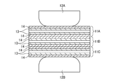
- FIG. 1A is a cross-sectional schematic diagram showing a state in which a pair of high-strength steel sheets each having a decarburized layer and a zinc-based plating layer are superposed before welding according to the first embodiment of the present invention.
- FIG. 1B is a schematic cross-sectional view showing a state in which the pair of high-tensile steel plates of FIG. 1A are resistance-welded.
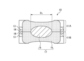
- FIG. 1C is a schematic sectional view showing a state where the pair of high-tensile steel plates of FIG. 1A are resistance-welded to form a nugget and a corona bond.
- FIG. 1A is a cross-sectional schematic diagram showing a state in which a pair of high-strength steel sheets each having a decarburized layer and a zinc-based plating layer are superposed before welding according to the first embodiment of the present invention.
- FIG. 1B is a schematic cross-sectional view showing a state in which the pair of high-tensile steel plates
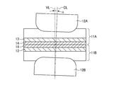
- FIG. 2A is a schematic diagram for explaining a state in which the axis of the welding electrode is not parallel to the perpendicular of the steel plate surface that contacts the welding electrode.
- FIG. 2B is a schematic diagram for explaining a state where there is a gap between the overlapping surfaces of the welded portions.
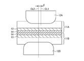
- FIG. 2C is a schematic diagram for explaining a state in which the axis of the other welding electrode does not exist on the extension line of the axis of the one welding electrode.
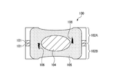
- FIG. 3A relates to the second embodiment of the present invention and shows a state in which a high-strength steel sheet having a decarburized layer on the overlapping surface and a zinc-based plated steel sheet having a zinc-based plating layer on the overlapping surface side are resistance-welded.
- FIG. 3B is a schematic cross-sectional view showing a state where the high-tensile steel plate and the zinc-based plated steel plate of FIG. 3A are resistance-welded to form a nugget and a corona bond.
- FIG. 4A is a schematic cross-sectional view showing a state in which a pair of high-strength steel plates each having a decarburization layer and a zinc-based plating layer on the welding electrode side are resistance-welded according to the third embodiment of the present invention.
- FIG. 4B is a schematic sectional view showing a state where the pair of high-tensile steel plates of FIG. 4A are resistance-welded to form a nugget and a corona bond.
- FIG. 5A is a schematic cross-sectional view showing a state in which three high-strength steel sheets having a decarburized layer and a zinc-based plated layer on both sides are resistance-welded according to the fourth embodiment of the present invention.
- FIG. 5B is a schematic sectional view showing a state in which the nugget and the corona bond are formed by resistance welding the three high-strength steel plates of FIG. 5A. It is a perspective view at the time of spot welding in the state where the gap C was provided.
- FIG. 7A is a schematic cross-sectional view showing a state in which a pair of high-strength steel plates with zinc-based plating on the overlapping surfaces are resistance-welded.
- FIG. 7B is a schematic sectional view showing a state in which HAZ cracks occur in the welded portion of FIG. 7A.
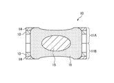
- the bonded structure 10 of the first embodiment includes a plurality (two in the embodiment shown in FIG. 1A) of high-strength steel plates 11 (11A, 11A, each having a decarburization layer 13 and a zinc-based plating layer 14). 11B) are resistance-welded to each other (resistance spot welding).
- the two high-tensile steel plates 11A and 11B that have been overlapped are sandwiched and pressed by a pair of upper and lower welding electrodes 12A and 12B of a spot welding apparatus, and the welding electrodes 12A and 11B are pressed.
- the contact part of high tension steel plate 11A, 11B fuse
- the nugget 15 is formed at the joint 17 between the high-strength steel plates 11A and 11B, and the corona bond 16 is formed around the nugget 15.
- the decarburization layer 13 is provided between the zinc-based plating layer 14 and the base material.
- the A3 point is higher than that of the base metal, and the presence of the decarburized layer 13 that does not easily undergo austenite transformation (reverse transformation) makes it difficult for the HAZ surface layer to have a coarse austenite structure during welding.
- the molten zinc of the zinc-based plating layer 14 is dispersed during welding and penetrates into the grain boundaries of the HAZ, thereby suppressing embrittlement due to zinc. That is, by forming the decarburized layer 13 between the base material of the high-strength steel plates 11A and 11B and the zinc-based plating layer 14, cracks can be prevented even when tensile stress acts even when molten zinc is present.
- the high-strength steel plate 11 has a chemical component with a carbon equivalent Ceq of 0.53% or more and a tensile strength of 590 MPa or more.
- the carbon equivalent Ceq is a value defined by the following formula (1).
- Ceq C + Si / 24 + Mn / 6 (1) (C, Si, and Mn represent the content (mass%) of each element, and are 0 when they are not contained.)
- the high-strength steel sheet 11 has a chemical composition with a carbon equivalent Ceq of 0.53% or more, so that an excellent balance between strength and elongation can be obtained.
- the carbon equivalent Ceq is preferably 0.6% or more, more preferably 0.7% or more.
- the high-tensile steel plate 11 is not particularly limited as long as it is 590 MPa class or higher, and may be, for example, a high-tensile steel plate of 780 MPa class or higher, 980 MPa class or higher.
- the high-tensile steel plate 11 has C: 0.05 to 0.60 mass%, Si: 0.01 to 3.0 mass%, Mn: 0.5 to 5.0 mass%, P: 0.05 mass%. % Or less (0% by mass is not included) and S: 0.05% by mass or less (0% by mass is not included) are preferable in terms of the following points.
- C 0.05 to 0.60 mass%
- Si 0.01 to 3.0 mass%
- Mn 0.5 to 5.0 mass%
- P 0.05 mass%.
- S 0.05% by mass or less
- the lower limit of the C content is preferably 0.05% or more.
- the upper limit of the C content is preferably 0.60% or less, more preferably 0.40% or less, and further preferably 0.20%.
- Si is an element that contributes to deoxidation. Therefore, the lower limit of the Si content is preferably 0.01% or more. On the other hand, if added excessively, the tempering softening resistance increases, the HAZ hardness increases, and cracking cannot be suppressed. Therefore, the upper limit of the Si content is preferably 3.00% or less, more preferably 2.00% or less, and further preferably 1.00% or less.
- Mn is an element that contributes to the improvement of hardenability and is an essential element for forming a hard structure such as martensite. Therefore, the lower limit of the Mn content is preferably 0.5% or more. On the other hand, if added excessively, the hardness of HAZ becomes high, and the occurrence of cracks cannot be suppressed. Therefore, the upper limit of the Mn content is preferably 5.0% or less, more preferably 2.5% or less, and further preferably 2.0% or less.
- P 0.05% or less (0% is not included)
- P is an element that is inevitably mixed in the steel, but it is easily segregated in the grains and grain boundaries, which lowers the toughness of the HAZ and prevents cracking from occurring. Therefore, the upper limit of the P content is preferably 0.05% or less, more preferably 0.04% or less, and further preferably 0.02% or less.
- S 0.05% or less (0% is not included)
- the upper limit of the S content is preferably 0.05% or less, more preferably 0.04% or less, and further preferably 0.02% or less.
- [Other metal elements] Other than the above C, Si, Mn, P and S, Al: 1.0% or less (including 0%), N: 0.01% or less (including 0%), 0.1% or less (including 0%) in total of Ti, V, Nb, and Zr, 2.0% or less (including 0%) in total of Cu, Ni, Cr and Mo, B: 0.01% or less (including 0%)
- the total content of Mg, Ca and REM is preferably 0.01% or less (including 0%).
- the balance is preferably Fe and inevitable impurities.
- the unavoidable impurities are impurities that are unavoidably mixed in during the production of steel, and may be contained in a range that does not impair the various properties of the steel.
- the decarburization layer 13 is formed by decarburizing the surface of the base material of the high-strength steel plate 11 before the zinc-based plating layer 14 is formed.
- the thickness of the decarburized layer is determined by measuring the thickness of the layer containing ferrite as the main layer with an optical microscope or an electron microscope for the sample immediately after the decarburization treatment.
- the thickness of the decarburized layer 13 is set to 5 ⁇ m or more, preferably 20 ⁇ m or more, more preferably 30 ⁇ m or more, still more preferably 45 ⁇ m or more, More preferably, it is 50 ⁇ m or more.
- the decarburized layer 13 has a thickness of 200 ⁇ m or less, preferably 160 ⁇ m or less, more preferably 120 ⁇ m or less, and further preferably 80 ⁇ m or less. To do.
- the structure of the decarburized layer 13 contains at least one of ferrite, bainite, and martensite. Since the softer the structure, the more difficult it is to crack, the decarburized layer 13 is more preferably a structure containing ferrite and containing one of bainite and martensite, and a structure containing ferrite and not containing bainite and martensite is more preferable. preferable.
- resistance spot welding is performed in a state in which the zinc-based plating layers 14 of the high-tensile steel plates 11A and 11B are overlapped so as to face each other, but an environment in which a disturbance as described below exists May be welded in.
- the upper limit of the hitting angle ⁇ is not particularly set, but if it is 10 degrees or less, even if the steel plates 11A and 11B are deformed and a portion having relatively high stress occurs near the corona bond 16, HAZ cracking can be suppressed by applying the embodiment.
- the gap C exists up to the gap between the overlapping surfaces at the welding point, and spot welding is performed with a gap between the steel sheets 11A and 11B due to a partial bulge around the welding point of the steel sheet 11 or the like. May occur.
- the upper limit of the gap C is not particularly set, but if it is 3 mm or less, even if local deformation is observed at the welded portion of the steel sheet 11 and local stress is generated in the vicinity of the corona bond 16. By applying this embodiment, HAZ cracks can be suppressed.
- the misalignment d is a case where spot welding is performed in a state in which the axial center CL1 of one welding electrode 12A and the axial center CL2 of the other welding electrode 12B are misaligned. Indicates the amount of misalignment between the shaft center CL1 of the above and the shaft center CL2 of the other welding electrode 12B.
- the upper limit of the misalignment d is not particularly set, but if it is 2 mm or less, even if the steel plate 11 is deformed and stress is generated in the vicinity of the corona bond 16, by applying this embodiment, HAZ cracking can be suppressed.
- the energization and pressurization patterns may be appropriately determined according to the required design conditions such as strength and rigidity.
- a two-step energization condition for changing the applied current value in two steps a pulse energization condition for applying a pulse current, or the like may be used.
- the amount of energy applied to the nugget 15 can be set with high accuracy, and the temperature and size of the nugget 15 can be set finely. Further, tempering and down slope can further suppress HAZ cracks, and thus can be appropriately added.
- the total plate thickness T of the high-tensile steel plates 11A and 11B is 1.5 mm or more and 6 mm or less. By setting the total plate thickness T in this range, it is possible to suppress HAZ cracks on the outside of the corona bond, the electrode indented portion, and the outside of the indented portion.
- the nugget 15 when the diameter D 1 of the nugget 15 increases, the nugget 15 grows in the plate thickness direction and the temperature of the electrode increases, so that the copper derived from the electrode and the zinc derived from the zinc plating are alloy layers. To form. Copper is also an element that causes embrittlement like zinc, and if an alloy layer of copper and zinc is excessively formed, the amount of copper that enters the grain boundaries of the HAZ increases and cracking becomes difficult to suppress. Therefore, the upper limit of the nugget diameter D 1 is preferably 7 ⁇ ⁇ t or less. Further, if the nugget diameter D 1 is too small, excessive stress concentration is likely to occur in the peripheral portion of the nugget, especially when there is a disturbance factor, which causes cracking after welding.
- the nugget diameter D 1 is preferably 2 ⁇ ⁇ t or more, where t is the thinner plate thickness of the steel plates 11 to be joined. From the same viewpoint as above, the nugget diameter D 1 preferably satisfies the relationship of D 1 > 3 mm, more preferably satisfies the relationship of D 1 > 5 mm, and satisfies the relationship of D 1 > 7 mm. More preferably.
- At least one steel plate among the plurality of steel plates to be resistance-welded has a chemical component with a carbon equivalent Ceq of 0.53% or more.
- the high-strength steel plate 11 has a tensile strength of 590 MPa or more
- the high-tensile steel plate 11 has a decarburization layer 13 between the zinc-based plating layer 14 formed on the surface of the overlapping surface side and the base material.
- the decarburized layer 13 has a thickness of 5 ⁇ m or more and 200 ⁇ m or less.
- the plurality of high-tensile steel plates 11A and 11B are overlapped with each other and the plurality of high-tensile steel plates 11A and 11B are joined by resistance spot welding. Further, it is possible to suppress the HAZ cracks on the electrode indentations and the outside of the indentations.
- the HAZ crack can be suppressed.
- B A state in which there is a gap C between the overlapping surfaces at the welded portion.
- C A state in which the axis CL1 of one welding electrode 12A and the axis CL2 of the other welding electrode 12B are misaligned.
- the joined structure 10 of the second embodiment is different from the joined structure 10 of the first embodiment in that it is a plate set of a high-strength steel plate 11 and a zinc-based plated steel plate 21.
- the bonded structure 10 includes a high-strength steel plate 11 having a decarburized layer 13 on the surface on the stacking surface side, and a zinc-based plating layer on the surface on the stacking surface side as well. And a zinc-based plated steel sheet 21 having 14 are resistance-welded. That is, the decarburized layer 13 of the high-strength steel sheet 11 is formed on the superposed surface adjacent to the zinc-based plated layer 14 of the zinc-based plated steel sheet 21 to be superposed.
- the base material of the zinc-based plated steel sheet 21 is not particularly limited, and may have tensile strength of 590 MPa or less, or mild steel.
- the bonded structure 10 of the third embodiment is similar to the bonded structure 10 of the first embodiment in that the decarburization layer 13 and the zinc-based plating layer 14 of the high-strength steel plates 11A and 11B are arranged on the welding electrode 12A, 12B side. different.
- the base materials having no zinc-based plating layer 14 are in contact with each other on the overlapping surface side of the high-tensile steel plates 11A and 11B.
- a decarburization layer 13 is provided between the base materials of the high-tensile steel plates 11A and 11B on the welding electrode 12A and 12B side and the zinc-based plating layer 14. Because of the interposition, the hot-dip zinc of the zinc-based plating layer 14 does not penetrate into the HAZ crystal grain boundaries of the high-strength steel sheets 11A and 11B, and HAZ cracking due to grain boundary embrittlement is prevented. Further, since the base materials not having the zinc-based plating layer 14 are in contact with each other on the overlapping surface side, there is no influence of molten zinc and no HAZ cracking occurs. Other configurations and operations are the same as those of the bonded structure 10 of the first embodiment.
- the base material of the high-tensile steel plates 11A, 11B, 11C and the zinc-based plating are provided on both the welding electrodes 12A, 12B side and the overlapping surface side. Since the decarburized layer 13 is interposed between the layer 14 and the layer 14, the molten zinc of the zinc-based plating layer 14 does not penetrate into the HAZ crystal grain boundaries of the high-strength steel sheets 11A, 11B, and 11C, resulting in grain boundary brittleness. HAZ cracks due to aging are prevented. Other configurations and operations are the same as those of the bonded structure 10 of the first embodiment.
- the welding machine was a servo pressurization type DC inverter, and the welding electrodes were dome-radius type (DR welding electrodes) chromium copper electrodes having a tip diameter of 6 mm (tip R40 mm) both at the top and bottom.
- the amount of cooling water flowing through the welding electrode was set to 1.5 L / min both at the top and bottom.
- the other welding conditions are shown below.
- the hitting angle ⁇ was set to 3 to 5 degrees in all the examples and the comparative examples.
- the hitting angle ⁇ was set by inclining the welding electrodes 12A and 12B by a predetermined angle from the state where the axial center CL of the welding electrodes 12A and 12B and the perpendicular VL of the welding surface match.
- Table 2 shows the evaluation results of the test together with the combination of the steel sheets 11, the depth (thickness) of the decarburized layer 13, and the welding conditions.
Landscapes
- Chemical & Material Sciences (AREA)
- Engineering & Computer Science (AREA)
- Mechanical Engineering (AREA)
- Chemical Kinetics & Catalysis (AREA)
- Materials Engineering (AREA)
- Metallurgy (AREA)
- Organic Chemistry (AREA)
- Resistance Welding (AREA)
- General Engineering & Computer Science (AREA)
Abstract
Provided are: a joined structure in which HAZ cracking can be suppressed on the outer side of a corona bond, at electrode indentation parts, and on the outer side of indentation parts at the time of spot-welding a plate set including steel plates having a galvanized layer; and a method for manufacturing the joined structure. At least one steel plate among a plurality of steel plates to be subjected to resistance welding is a high-tensile steel plate (11) having a tensile strength of 590 MPa or greater and including a chemical component having a carbon equivalent Ceq of 0.53% or greater. The high-tensile steel plate (11) has a decarburized layer (13) provided either: between a matrix and a zinc-based plating layer (14) formed on a surface on a superposition surface side and/or a surface on a welding electrode side; or on a superposition surface adjacent to a zinc-based plating layer (14) of a zinc-based plating steel plate (21) to be superposed. The decarburized layer (13) has a thickness of from 5 µm to 200 µm.
Description
本発明は、接合構造体及び接合構造体の製造方法に関する。
The present invention relates to a bonded structure and a method for manufacturing the bonded structure.
近年、CO2排出量の削減を目的とした車体軽量化や衝突安全性強化を実現するため、自動車のボディ骨格等に高強度鋼板(High Tensile Strength Steel;HTSS)が広く採用されている。また、自動車の車体の組立や部品の取付けなどでは、主として、スポット溶接が使用されており、高張力鋼板の溶接にも適用されている。
2. Description of the Related Art In recent years, high-strength steel sheets (HTSS) have been widely used for automobile body frameworks and the like in order to reduce vehicle weight and enhance collision safety for the purpose of reducing CO 2 emissions. Further, spot welding is mainly used in the assembly of automobile bodies and attachment of parts, and is also applied to welding of high-tensile steel plates.
また、自動車用鋼板には、防錆化の観点から、耐食性に優れた亜鉛系めっきが施された高張力鋼板も多用されている。図7A及び図7Bは、重ね合わせ面に亜鉛系めっきが施された一対の高張力鋼板が抵抗スポット溶接される状態を示している。具体的に、接合構造体100は、表面に亜鉛系めっき層101を有する高張力鋼板102A,102Bを、スポット溶接装置の上下一対の溶接電極103A,103Bにより挟持して加圧し、溶接電極103A,103B間に通電することで形成される。この場合、図7Bに示すように、高張力鋼板102A,102Bの接合部にはナゲット104が形成されると共に、ナゲット104の周囲にコロナボンド105が形成される。
Also, from the viewpoint of rust prevention, high-strength steel sheets coated with zinc-based plating with excellent corrosion resistance are often used for automobile steel sheets. FIGS. 7A and 7B show a state in which a pair of high-tensile steel plates each having a zinc-based plating on the overlapping surfaces are resistance spot welded. Specifically, the bonded structure 100 sandwiches and presses high- tensile steel plates 102A and 102B having a zinc-based plating layer 101 on the surface between a pair of upper and lower welding electrodes 103A and 103B of a spot welding apparatus, and welds the welding electrodes 103A and 103A. It is formed by energizing between 103B. In this case, as shown in FIG. 7B, a nugget 104 is formed at the joint between the high- strength steel plates 102A and 102B, and a corona bond 105 is formed around the nugget 104.
しかしながら、高張力鋼板102A,102Bには、溶接時には、プレス加工による残留応力や溶接後の熱収縮により溶接部に引張応力が働く。このため、引張応力が働く高張力鋼板102A,102Bの溶接熱影響部(Heat-Affected Zone;HAZ)の結晶粒界に亜鉛系めっき層101の溶融した亜鉛が侵入すると、粒界が脆化(溶融金属脆性、LME)してコロナボンド105の外側部分および電極圧痕部、圧痕部外側にHAZ割れ106が発生するという課題がある。
However, tensile stress acts on the high- strength steel plates 102A and 102B during welding due to residual stress due to press working and thermal contraction after welding. Therefore, when the molten zinc of the zinc-based plating layer 101 enters the crystal grain boundaries of the heat-affected zone (HAZ) of the high- strength steel plates 102A and 102B where tensile stress acts, the grain boundaries become brittle ( There is a problem that HAZ cracks 106 are generated on the outer portion of the corona bond 105, the electrode indentation portion, and the outside of the indentation portion due to molten metal brittleness (LME).
特許文献1には、溶接部の割れ発生を防止するようにした高強度めっき鋼板のスポット溶接方法が開示されている。即ち、このスポット溶接では、(A)溶接後の保持時間を一定の値以上に設定し、溶接通電時間を一定の範囲内に減少させる、(B)溶接通電後、引き続き一定の条件で後通電を行う、(C)溶接後の保持時間を一定の値以上に設定し、溶接通電後、加圧力を一定の範囲内で増加させる、(D)一定の組成を有する高強度めっき鋼板を用い、溶接後の保持時間を一定の値以上に設定して溶接する、のいずれかの方法により、溶接部の割れ発生を防止することが記載されている。
Patent Document 1 discloses a spot welding method for a high-strength plated steel sheet that prevents the occurrence of cracks in the welded portion. In other words, in this spot welding, (A) the holding time after welding is set to a certain value or more, and the welding energization time is reduced within a certain range. (B) After welding energization, post-energization is continued under certain conditions. (C) The holding time after welding is set to a certain value or more, and the welding pressure is increased within a certain range after the welding current is passed. (D) Using a high strength plated steel sheet having a certain composition, It is described that the occurrence of cracks in the welded portion is prevented by any one of the method of welding after setting the holding time after welding to a certain value or more.
特許文献2には、溶接箇所の重ね合わせ面が亜鉛系めっきで被覆された鋼板のスポット溶接において、総板厚に応じた溶接後の保持時間を設定することにより、打角、鋼板間のギャップ、溶接電極の芯ずれなどの外乱因子が存在しても、コロナボンド直外及びコロナボンドのナゲット際に発生する割れを抑制して、高品質のスポット溶接継手を形成することが記載されている。
In Patent Document 2, in spot welding of a steel sheet having a superposed surface of a welded portion coated with zinc-based plating, a hitting angle and a gap between steel sheets are set by setting a holding time after welding according to the total sheet thickness. It is described that even if there is a disturbance factor such as misalignment of the welding electrode, cracks occurring directly outside the corona bond and at the corona bond nugget are suppressed, and a high quality spot welded joint is formed. .
また、特許文献3には、Ti、Nb、V、Mo、Zrなどの鋼板成分を添加することで、オーステナイト結晶粒の粗大化を抑制し、複相組織とすることで、亜鉛の結晶粒界への侵入を抑制することができる亜鉛めっき高張力鋼板が開示されている。
Further, in Patent Document 3, by adding steel plate components such as Ti, Nb, V, Mo, and Zr, coarsening of austenite crystal grains is suppressed, and a multiphase structure is formed, whereby a zinc grain boundary. There is disclosed a galvanized high-strength steel sheet capable of suppressing the invasion into the steel sheet.
しかしながら、特許文献1及び2では、板組の総板厚が大きくなると、溶接後の保持時間が長時間となるため、タクトタイムが長くなり、コストアップの要因となる。また、特許文献3では、特殊な成分添加が必要であり、機械的特性の確保、製造安定性を阻害する可能性がある。
However, in Patent Documents 1 and 2, when the total plate thickness of the plate assembly becomes large, the holding time after welding becomes long, and the tact time becomes long, which causes a cost increase. Further, in Patent Document 3, it is necessary to add a special component, and there is a possibility that mechanical properties are secured and production stability is impaired.
本発明は、前述した課題に鑑みてなされたものであり、その目的は、亜鉛めっき層を有する鋼板を含む板組をスポット溶接する際のコロナボンド外側および電極圧痕部、圧痕部外側におけるHAZ割れを抑制できる接合構造体及び接合構造体の製造方法を提供することにある。
The present invention has been made in view of the above-mentioned problems, and an object thereof is HAZ cracking on the outside of the corona bond and the electrode indentation portion and the indentation portion when spot welding a plate set including a steel sheet having a galvanized layer. It is an object of the present invention to provide a bonded structure and a method for manufacturing the bonded structure that can suppress the occurrence of the above.
本発明の上記目的は、接合構造体に係る下記(1)の構成により達成される。
(1) 重ね合わされた複数の鋼板が抵抗溶接されてなる接合構造体であって、
前記複数の鋼板の内、少なくとも1枚の前記鋼板は、炭素当量Ceqが0.53%以上となる化学成分を有し、引張強度が590MPa以上である高張力鋼板であり、
前記高張力鋼板は、重ね合わせ面側と溶接電極側の少なくとも一方の表面に形成される亜鉛系めっき層と母材との間、又は、重ね合される亜鉛系めっき鋼板の亜鉛系めっき層と隣り合う重ね合わせ面に脱炭層を有し、
前記脱炭層は、5μm以上、200μm以下の厚さを有することを特徴とする接合構造体。
ただし、前記炭素当量Ceqは下記(1)式で定義される値である。
Ceq=C+Si/24+Mn/6 ・・・(1)
(C、Si及びMnは、各元素の含有量(質量%)を表し、含有しない場合は0とする。) The above object of the present invention is achieved by the following constitution (1) of the bonded structure.
(1) A joined structure in which a plurality of superposed steel plates are resistance-welded,
Among the plurality of steel plates, at least one of the steel plates is a high-tensile steel plate having a chemical composition such that the carbon equivalent Ceq is 0.53% or more, and the tensile strength is 590 MPa or more,
The high-strength steel sheet is between a base material and a zinc-based plating layer formed on at least one surface of the overlapping surface side and the welding electrode side, or a zinc-based plating layer of a zinc-based plated steel sheet to be overlaid. Has a decarburized layer on the adjacent superposed surfaces,
The bonded structure, wherein the decarburized layer has a thickness of 5 μm or more and 200 μm or less.
However, the carbon equivalent Ceq is a value defined by the following formula (1).
Ceq = C + Si / 24 + Mn / 6 (1)
(C, Si, and Mn represent the content (mass%) of each element, and are 0 when they are not contained.)
また、接合構造体に係る本発明の好ましい実施形態は、以下の(2)に関する。
(2) 前記接合構造体のナゲットにおけるナゲット径D1が、D1>3mmの関係を満足する、上記(1)に記載の接合構造体。 A preferred embodiment of the present invention related to the bonded structure relates to (2) below.
(2) The bonded structure according to (1), wherein the nugget diameter D 1 in the nugget of the bonded structure satisfies the relationship of D 1 > 3 mm.
また、本発明の上記目的は、接合構造体の製造方法に係る下記(3)の構成により達成される。
(3) 上記(1)又は(2)に記載の接合構造体を抵抗スポット溶接により製造する接合構造体の製造方法であって、
複数の前記高張力鋼板同士、又は少なくとも一枚の前記高張力鋼板と前記亜鉛系めっき鋼板とを重ね合わせ、
前記複数の高張力鋼板同士、又は前記少なくとも一枚の高張力鋼板と前記亜鉛系めっき鋼板を抵抗スポット溶接により接合する接合構造体の製造方法。 Further, the above object of the present invention is achieved by the following configuration (3) of the method for manufacturing a bonded structure.
(3) A method for manufacturing a bonded structure according to the above (1) or (2), which is manufactured by resistance spot welding.
A plurality of the high-tensile steel plates, or at least one of the high-tensile steel plate and the zinc-based plated steel plate,
A method for manufacturing a joint structure, wherein the plurality of high-tensile steel plates are joined together, or the at least one high-tensile steel plate and the zinc-based plated steel plate are joined by resistance spot welding.
また、接合構造体の製造方法に係る本発明の好ましい実施形態は、以下の(4)に関する。
(4) 前記抵抗スポット溶接は、下記(a)~(c)の少なくとも一つの条件において行われる、上記(3)に記載の接合構造体の製造方法。
(a)前記溶接電極の軸芯と、前記溶接電極と接触する前記鋼板表面の垂線とが平行でない状態。
(b)溶接箇所における重ね合わせ面の間にギャップを有した状態。
(c)一方の前記溶接電極の軸芯と他方の前記溶接電極の軸芯とが芯ずれした状態。 A preferred embodiment of the present invention related to the method for manufacturing a bonded structure relates to (4) below.
(4) The method for manufacturing a bonded structure according to (3), wherein the resistance spot welding is performed under at least one of the following conditions (a) to (c).
(A) A state in which the axis of the welding electrode is not parallel to the perpendicular to the surface of the steel sheet that contacts the welding electrode.
(B) A state in which there is a gap between the overlapping surfaces at the welding location.
(C) A state in which the axis of one of the welding electrodes and the axis of the other welding electrode are misaligned.
本発明の接合構造体によれば、抵抗溶接される複数の鋼板の内、少なくとも1枚の鋼板は、炭素当量Ceqが0.53%以上となる化学成分を有し、引張強度が590MPa以上である高張力鋼板であり、高張力鋼板は、重ね合わせ面側と溶接電極側の少なくとも一方の表面に形成される亜鉛系めっき層と母材との間、又は、重ね合される亜鉛系めっき鋼板の亜鉛系めっき層と隣り合う重ね合わせ面に脱炭層を有し、脱炭層は、5μm以上、200μm以下の厚さを有するので、コロナボンド外側および電極圧痕部、圧痕部外側におけるHAZ割れを抑制できる。
According to the bonded structure of the present invention, at least one of the plurality of steel plates to be resistance-welded has a chemical composition with a carbon equivalent Ceq of 0.53% or more and a tensile strength of 590 MPa or more. A certain high-tensile steel plate, the high-tensile steel plate, between the zinc-based plating layer and the base material formed on at least one surface of the overlapping surface side and the welding electrode side, or a zinc-based plated steel sheet to be overlapped Has a decarburized layer on the superposed surface adjacent to the zinc-based plating layer, and the decarburized layer has a thickness of 5 μm or more and 200 μm or less. it can.
また、本発明の接合構造体の製造方法によれば、複数の上記高張力鋼板同士、又は少なくとも一枚の上記高張力鋼板と上記亜鉛系めっき鋼板とを重ね合わせ、複数の高張力鋼板同士、又は少なくとも一枚の高張力鋼板と亜鉛系めっき鋼板を抵抗スポット溶接により接合するので、コロナボンド外側および電極圧痕部、圧痕部外側におけるHAZ割れを抑制できる。
Further, according to the method for manufacturing a joined structure of the present invention, a plurality of the high-tensile steel plates, or at least one of the high-tensile steel plate and the zinc-based plated steel plate, a plurality of high-tensile steel plates, Alternatively, since at least one high-tensile steel plate and the zinc-based plated steel plate are joined by resistance spot welding, it is possible to suppress HAZ cracks on the outside of the corona bond, the electrode indentation portion, and the indentation portion.
以下、本発明の各実施形態に係る接合構造体、及びその製造方法を図面に基づいて詳細に説明する。
Hereinafter, a bonded structure according to each embodiment of the present invention and a manufacturing method thereof will be described in detail with reference to the drawings.
(第1実施形態)
第1実施形態の接合構造体10は、図1Aに示すように、脱炭層13及び亜鉛系めっき層14をそれぞれ有する複数(図1Aに示す実施形態では2枚)の高張力鋼板11(11A,11B)同士を抵抗溶接(抵抗スポット溶接)することで形成される。 (First embodiment)
As shown in FIG. 1A, the bondedstructure 10 of the first embodiment includes a plurality (two in the embodiment shown in FIG. 1A) of high-strength steel plates 11 (11A, 11A, each having a decarburization layer 13 and a zinc-based plating layer 14). 11B) are resistance-welded to each other (resistance spot welding).
第1実施形態の接合構造体10は、図1Aに示すように、脱炭層13及び亜鉛系めっき層14をそれぞれ有する複数(図1Aに示す実施形態では2枚)の高張力鋼板11(11A,11B)同士を抵抗溶接(抵抗スポット溶接)することで形成される。 (First embodiment)
As shown in FIG. 1A, the bonded
具体的には、図1Bに示すように、重ね合された2枚の高張力鋼板11A,11Bを、スポット溶接装置の上下一対の溶接電極12A,12Bにより挟持して加圧し、溶接電極12A,12B間に通電することで、高張力鋼板11A,11Bの接触部が溶融して接合部17が形成される。これにより、図1Cに示すように、高張力鋼板11A,11Bの接合部17には、ナゲット15が形成されると共に、ナゲット15の周囲にコロナボンド16が形成される。
Specifically, as shown in FIG. 1B, the two high- tensile steel plates 11A and 11B that have been overlapped are sandwiched and pressed by a pair of upper and lower welding electrodes 12A and 12B of a spot welding apparatus, and the welding electrodes 12A and 11B are pressed. By energizing between 12B, the contact part of high tension steel plate 11A, 11B fuse | melts, and the joint part 17 is formed. As a result, as shown in FIG. 1C, the nugget 15 is formed at the joint 17 between the high- strength steel plates 11A and 11B, and the corona bond 16 is formed around the nugget 15.
ここで、本実施形態の高張力鋼板11A,11Bでは、脱炭層13が亜鉛系めっき層14と母材との間に設けられている。母材と比較してA3点が高く、オーステナイト変態(逆変態)しにくい脱炭層13が存在することで、溶接時にHAZ表層が粗大なオーステナイト組織となりにくい。その結果、溶接時に亜鉛系めっき層14の溶融した亜鉛が分散してHAZの結晶粒界へ侵入する、亜鉛による脆化が抑制される。つまり、脱炭層13を高張力鋼板11A,11Bの母材と亜鉛系めっき層14との間に形成することで、溶融亜鉛存在時にたとえ引張応力が働いたとしても割れを防止できる。
Here, in the high- strength steel sheets 11A and 11B of the present embodiment, the decarburization layer 13 is provided between the zinc-based plating layer 14 and the base material. The A3 point is higher than that of the base metal, and the presence of the decarburized layer 13 that does not easily undergo austenite transformation (reverse transformation) makes it difficult for the HAZ surface layer to have a coarse austenite structure during welding. As a result, the molten zinc of the zinc-based plating layer 14 is dispersed during welding and penetrates into the grain boundaries of the HAZ, thereby suppressing embrittlement due to zinc. That is, by forming the decarburized layer 13 between the base material of the high- strength steel plates 11A and 11B and the zinc-based plating layer 14, cracks can be prevented even when tensile stress acts even when molten zinc is present.
以下、本実施形態の接合構造体10に使用される高張力鋼板11について、説明する。
高張力鋼板11は、炭素当量Ceqが0.53%以上となる化学成分を有し、引張強度が590MPa以上の強度を有する。
ただし、前記炭素当量Ceqは下記(1)式で定義される値である。
Ceq=C+Si/24+Mn/6 ・・・(1)
(C、Si及びMnは、各元素の含有量(質量%)を表し、含有しない場合は0とする。) Hereinafter, the high-tensile steel plate 11 used for the bonded structure 10 of the present embodiment will be described.
The high-strength steel plate 11 has a chemical component with a carbon equivalent Ceq of 0.53% or more and a tensile strength of 590 MPa or more.
However, the carbon equivalent Ceq is a value defined by the following formula (1).
Ceq = C + Si / 24 + Mn / 6 (1)
(C, Si, and Mn represent the content (mass%) of each element, and are 0 when they are not contained.)
高張力鋼板11は、炭素当量Ceqが0.53%以上となる化学成分を有し、引張強度が590MPa以上の強度を有する。
ただし、前記炭素当量Ceqは下記(1)式で定義される値である。
Ceq=C+Si/24+Mn/6 ・・・(1)
(C、Si及びMnは、各元素の含有量(質量%)を表し、含有しない場合は0とする。) Hereinafter, the high-
The high-
However, the carbon equivalent Ceq is a value defined by the following formula (1).
Ceq = C + Si / 24 + Mn / 6 (1)
(C, Si, and Mn represent the content (mass%) of each element, and are 0 when they are not contained.)
高張力鋼板11は、炭素当量Ceqが0.53%以上となる化学成分を有することで、優れた強度と伸びのバランスが得られる。なお、炭素当量Ceqは、好ましくは0.6%以上、より好ましくは0.7%以上である。
なお、上記高張力鋼板11としては、590MPa級以上のものであれば特に限定されず、例えば、780MPa級以上、980MPa級以上の高張力鋼板であってもよい。 The high-strength steel sheet 11 has a chemical composition with a carbon equivalent Ceq of 0.53% or more, so that an excellent balance between strength and elongation can be obtained. The carbon equivalent Ceq is preferably 0.6% or more, more preferably 0.7% or more.
The high-tensile steel plate 11 is not particularly limited as long as it is 590 MPa class or higher, and may be, for example, a high-tensile steel plate of 780 MPa class or higher, 980 MPa class or higher.
なお、上記高張力鋼板11としては、590MPa級以上のものであれば特に限定されず、例えば、780MPa級以上、980MPa級以上の高張力鋼板であってもよい。 The high-
The high-
また、高張力鋼板11は、C:0.05~0.60質量%、Si:0.01~3.0質量%、Mn:0.5~5.0質量%、P:0.05質量%以下(0質量%は含まない)、S:0.05質量%以下(0質量%は含まない)の化学成分を有することが、以下の点で好ましい。以下に、鋼中に含まれる各元素(C、Si、Mn、P、S及びその他の金属元素)の含有量の望ましい範囲及びその範囲の限定理由を以下で説明する。なお、各元素の含有量の%表示は全て質量%である。また、「~」とは、その下限の値以上、その上限の値以下であることを意味する。
The high-tensile steel plate 11 has C: 0.05 to 0.60 mass%, Si: 0.01 to 3.0 mass%, Mn: 0.5 to 5.0 mass%, P: 0.05 mass%. % Or less (0% by mass is not included) and S: 0.05% by mass or less (0% by mass is not included) are preferable in terms of the following points. Below, the desirable range of the content of each element (C, Si, Mn, P, S and other metal elements) contained in steel and the reason for limiting the range will be described below. In addition, all percentages of the content of each element are% by mass. Further, “to” means that the value is not less than the lower limit value and not more than the upper limit value.
[C:0.05~0.60%]
Cは鋼の母材強度向上に寄与する元素であるため、高張力鋼板には必須な元素である。そのため、C含有量の下限は0.05%以上とすることが好ましい。一方、過剰に添加すると、HAZの硬度が高くなり、割れ発生が抑制できない。そのため、C含有量の上限は、好ましくは0.60%以下、より好ましくは0.40%以下、更に好ましくは0.20%とする。 [C: 0.05-0.60%]
Since C is an element that contributes to improving the strength of the base metal of steel, it is an essential element for high-strength steel sheets. Therefore, the lower limit of the C content is preferably 0.05% or more. On the other hand, if added excessively, the hardness of HAZ becomes high, and the occurrence of cracks cannot be suppressed. Therefore, the upper limit of the C content is preferably 0.60% or less, more preferably 0.40% or less, and further preferably 0.20%.
[Si:0.01~3.0%]
Siは脱酸に寄与する元素である。そのため、Si含有量の下限は0.01%以上とすることが好ましい。一方、過剰に添加すると、焼戻し軟化抵抗が高くなり、HAZの硬度が高くなり、割れ発生が抑制できない。そのため、Si含有量の上限は、好ましくは3.00%以下、より好ましくは2.00%以下、更に好ましくは1.00%以下とする。 [Si: 0.01 to 3.0%]
Si is an element that contributes to deoxidation. Therefore, the lower limit of the Si content is preferably 0.01% or more. On the other hand, if added excessively, the tempering softening resistance increases, the HAZ hardness increases, and cracking cannot be suppressed. Therefore, the upper limit of the Si content is preferably 3.00% or less, more preferably 2.00% or less, and further preferably 1.00% or less.
[Mn:0.5~5.0%]
Mnは焼入れ性向上に寄与する元素であり、マルテンサイトなど硬質組織を生成するために必須な元素である。そのため、Mn含有量の下限は0.5%以上とすることが好ましい。一方、過剰に添加すると、HAZの硬度が高くなり、割れ発生が抑制できない。そのため、Mn含有量の上限は、好ましくは5.0%以下、より好ましくは2.5%以下、更に好ましくは2.0%以下とする。 [Mn: 0.5-5.0%]
Mn is an element that contributes to the improvement of hardenability and is an essential element for forming a hard structure such as martensite. Therefore, the lower limit of the Mn content is preferably 0.5% or more. On the other hand, if added excessively, the hardness of HAZ becomes high, and the occurrence of cracks cannot be suppressed. Therefore, the upper limit of the Mn content is preferably 5.0% or less, more preferably 2.5% or less, and further preferably 2.0% or less.
[P:0.05%以下(0%は含まない)]
Pは不可避的に鋼中へ混入する元素であるが、粒内および粒界へ偏析しやすく、HAZの靭性を低下し、割れ発生が抑制できない。そのため、P含有量の上限は、好ましくは0.05%以下、より好ましくは0.04%以下、更に好ましくは0.02%以下とする。 [P: 0.05% or less (0% is not included)]
P is an element that is inevitably mixed in the steel, but it is easily segregated in the grains and grain boundaries, which lowers the toughness of the HAZ and prevents cracking from occurring. Therefore, the upper limit of the P content is preferably 0.05% or less, more preferably 0.04% or less, and further preferably 0.02% or less.
[S:0.05%以下(0%は含まない)]
SはP同様、不可避的に鋼中へ混入する元素であるが、粒内および粒界へ偏析しやすく、HAZの靭性を低下し、割れ発生が抑制できない。そのため、S含有量の上限は、好ましくは0.05%以下、より好ましくは0.04%以下、更に好ましくは0.02%以下とする。 [S: 0.05% or less (0% is not included)]
Like P, S is an element that is unavoidably mixed into the steel, but it is easily segregated within the grains and grain boundaries, which reduces the toughness of the HAZ and prevents cracking from occurring. Therefore, the upper limit of the S content is preferably 0.05% or less, more preferably 0.04% or less, and further preferably 0.02% or less.
[その他の金属元素]
上記C、Si、Mn、P及びS以外は、
Al:1.0%以下(0%を含む)、
N:0.01%以下(0%を含む)、
Ti、V、Nb、Zrの合計で0.1%以下(0%を含む)、
Cu、Ni、CrおよびMoの合計で2.0%以下(0%を含む)、
B:0.01%以下(0%を含む)
Mg、Ca、REMの合計で0.01%以下(0%を含む)であることが好ましい。その他、残部はFe及び不可避的不純物であることが好ましい。不可避的不純物は、鋼の製造時に不可避的に混入する不純物であり、鋼の諸特性を害さない範囲で含有され得る。 [Other metal elements]
Other than the above C, Si, Mn, P and S,
Al: 1.0% or less (including 0%),
N: 0.01% or less (including 0%),
0.1% or less (including 0%) in total of Ti, V, Nb, and Zr,
2.0% or less (including 0%) in total of Cu, Ni, Cr and Mo,
B: 0.01% or less (including 0%)
The total content of Mg, Ca and REM is preferably 0.01% or less (including 0%). In addition, the balance is preferably Fe and inevitable impurities. The unavoidable impurities are impurities that are unavoidably mixed in during the production of steel, and may be contained in a range that does not impair the various properties of the steel.
一方、脱炭層13は、亜鉛系めっき層14が形成される前に、高張力鋼板11の母材の表面を脱炭処理することで形成される。なお、脱炭層の厚さは、脱炭処理直後のサンプルに対して、光学顕微鏡や電子顕微鏡などによるフェライトを主層とする層の厚さを測定することなどにより判断する。
On the other hand, the decarburization layer 13 is formed by decarburizing the surface of the base material of the high-strength steel plate 11 before the zinc-based plating layer 14 is formed. The thickness of the decarburized layer is determined by measuring the thickness of the layer containing ferrite as the main layer with an optical microscope or an electron microscope for the sample immediately after the decarburization treatment.
また、脱炭層13を形成することによる割れ防止効果を有効に発揮させるためには、脱炭層13の厚さを5μm以上とし、好ましくは20μm以上、より好ましくは30μm以上、更に好ましくは45μm以上、より更に好ましくは50μm以上とする。しかし、脱炭層13が過剰に厚くなると、引張強度や疲労強度が低下するため、脱炭層13の厚さは、200μm以下とし、好ましくは160μm以下、より好ましくは120μm以下、更に好ましくは80μm以下とする。
In order to effectively exhibit the crack prevention effect by forming the decarburized layer 13, the thickness of the decarburized layer 13 is set to 5 μm or more, preferably 20 μm or more, more preferably 30 μm or more, still more preferably 45 μm or more, More preferably, it is 50 μm or more. However, when the decarburized layer 13 is excessively thick, the tensile strength and the fatigue strength are reduced. Therefore, the decarburized layer 13 has a thickness of 200 μm or less, preferably 160 μm or less, more preferably 120 μm or less, and further preferably 80 μm or less. To do.
また、脱炭層13の組織は、フェライト、ベイナイト、マルテンサイトのうち少なくとも1種を含むものとする。軟質な組織ほど割れにくくなるため、脱炭層13は、フェライトを含み、ベイナイトとマルテンサイトのどちらか一種を含む組織であることがより好ましく、フェライトを含み、ベイナイト及びマルテンサイトは含まない組織がさらに好ましい。
The structure of the decarburized layer 13 contains at least one of ferrite, bainite, and martensite. Since the softer the structure, the more difficult it is to crack, the decarburized layer 13 is more preferably a structure containing ferrite and containing one of bainite and martensite, and a structure containing ferrite and not containing bainite and martensite is more preferable. preferable.
そして、本実施形態では、高張力鋼板11A,11Bの亜鉛系めっき層14同士が対向するように重ね合わせた状態で、抵抗スポット溶接が施されるが、以下に示すような外乱が存在する環境で溶接される場合がある。
Then, in the present embodiment, resistance spot welding is performed in a state in which the zinc-based plating layers 14 of the high- tensile steel plates 11A and 11B are overlapped so as to face each other, but an environment in which a disturbance as described below exists May be welded in.
(打角θ)
スポット溶接では、鋼板11A,11Bの表面に対して溶接電極を垂直に当てるのが通常であるが、溶接電極12A,12Bの軸芯CLと、鋼板11A,11B表面の垂線VLとが平行でない状態で行われることがあり、図2Aに示すように、溶接電極12A,12Bの軸芯CLと、鋼板11A,11B表面の垂線VLとがなす角度を、打角θとしている。打角θの上限は特に設けるものではないが、10度以下であれば、鋼板11A,11Bが変形してコロナボンド16の近傍に比較的応力が高くなる箇所が生じる場合であっても、本実施形態を適用することで、HAZ割れを抑制できる。 (Batting angle θ)
In spot welding, it is usual that the welding electrodes are vertically applied to the surfaces of the steel plates 11A and 11B, but the axial center CL of the welding electrodes 12A and 12B is not parallel to the perpendicular line VL of the surfaces of the steel plates 11A and 11B. 2A, as shown in FIG. 2A, the angle formed by the axis CL of the welding electrodes 12A and 12B and the perpendicular VL of the surfaces of the steel plates 11A and 11B is defined as the striking angle θ. The upper limit of the hitting angle θ is not particularly set, but if it is 10 degrees or less, even if the steel plates 11A and 11B are deformed and a portion having relatively high stress occurs near the corona bond 16, HAZ cracking can be suppressed by applying the embodiment.
スポット溶接では、鋼板11A,11Bの表面に対して溶接電極を垂直に当てるのが通常であるが、溶接電極12A,12Bの軸芯CLと、鋼板11A,11B表面の垂線VLとが平行でない状態で行われることがあり、図2Aに示すように、溶接電極12A,12Bの軸芯CLと、鋼板11A,11B表面の垂線VLとがなす角度を、打角θとしている。打角θの上限は特に設けるものではないが、10度以下であれば、鋼板11A,11Bが変形してコロナボンド16の近傍に比較的応力が高くなる箇所が生じる場合であっても、本実施形態を適用することで、HAZ割れを抑制できる。 (Batting angle θ)
In spot welding, it is usual that the welding electrodes are vertically applied to the surfaces of the
(ギャップC)
ギャップCは、図2Bに示すように、溶接箇所における重ね合わせ面間のすきまであり、鋼板11の溶接箇所周辺の部分的な盛り上がり等で、鋼板11A,11B間に隙間を有したままスポット溶接が行われる場合がある。ギャップCの上限は特に設けるものではないが、3mm以下であれば、鋼板11の溶接箇所に局所的な変形が見られ、コロナボンド16の近傍に局所的な応力が発生する場合であっても、本実施形態を適用することで、HAZ割れを抑制できる。 (Gap C)
As shown in FIG. 2B, the gap C exists up to the gap between the overlapping surfaces at the welding point, and spot welding is performed with a gap between the steel sheets 11A and 11B due to a partial bulge around the welding point of the steel sheet 11 or the like. May occur. The upper limit of the gap C is not particularly set, but if it is 3 mm or less, even if local deformation is observed at the welded portion of the steel sheet 11 and local stress is generated in the vicinity of the corona bond 16. By applying this embodiment, HAZ cracks can be suppressed.
ギャップCは、図2Bに示すように、溶接箇所における重ね合わせ面間のすきまであり、鋼板11の溶接箇所周辺の部分的な盛り上がり等で、鋼板11A,11B間に隙間を有したままスポット溶接が行われる場合がある。ギャップCの上限は特に設けるものではないが、3mm以下であれば、鋼板11の溶接箇所に局所的な変形が見られ、コロナボンド16の近傍に局所的な応力が発生する場合であっても、本実施形態を適用することで、HAZ割れを抑制できる。 (Gap C)
As shown in FIG. 2B, the gap C exists up to the gap between the overlapping surfaces at the welding point, and spot welding is performed with a gap between the
(芯ずれd)
芯ずれdは、図2Cに示すように、一方の溶接電極12Aの軸芯CL1と他方の溶接電極12Bの軸芯CL2とが芯ずれした状態でスポット溶接が行われる場合であり、溶接電極12Aの軸芯CL1と他方の溶接電極12Bの軸芯CL2との芯ずれ量をさす。芯ずれdの上限は特に設けるものではないが、2mm以下であれば、鋼板11が変形して、コロナボンド16の近傍で応力が生じる場合であっても、本実施形態を適用することで、HAZ割れを抑制できる。 (Center misalignment d)
As shown in FIG. 2C, the misalignment d is a case where spot welding is performed in a state in which the axial center CL1 of onewelding electrode 12A and the axial center CL2 of the other welding electrode 12B are misaligned. Indicates the amount of misalignment between the shaft center CL1 of the above and the shaft center CL2 of the other welding electrode 12B. The upper limit of the misalignment d is not particularly set, but if it is 2 mm or less, even if the steel plate 11 is deformed and stress is generated in the vicinity of the corona bond 16, by applying this embodiment, HAZ cracking can be suppressed.
芯ずれdは、図2Cに示すように、一方の溶接電極12Aの軸芯CL1と他方の溶接電極12Bの軸芯CL2とが芯ずれした状態でスポット溶接が行われる場合であり、溶接電極12Aの軸芯CL1と他方の溶接電極12Bの軸芯CL2との芯ずれ量をさす。芯ずれdの上限は特に設けるものではないが、2mm以下であれば、鋼板11が変形して、コロナボンド16の近傍で応力が生じる場合であっても、本実施形態を適用することで、HAZ割れを抑制できる。 (Center misalignment d)
As shown in FIG. 2C, the misalignment d is a case where spot welding is performed in a state in which the axial center CL1 of one
特に、本実施形態の接合構造体の製造方法によれば、10度以下の打角θ、3mm以下のギャップC、及び2mm以下の芯ずれdの条件が2つ以上満足する場合あっても、HAZ割れを抑制できる。
In particular, according to the method for manufacturing a bonded structure of the present embodiment, even if two or more conditions of a hit angle θ of 10 degrees or less, a gap C of 3 mm or less, and a misalignment d of 2 mm or less are satisfied, HAZ cracking can be suppressed.
なお、抵抗スポット溶接における溶接条件には、特に制限はなく、必要とする強度や剛性等の設計条件に応じて、通電、加圧パターンを適宜決定すればよい。例えば、スポット溶接であれば、印加電流値を二段階に変化させる二段通電条件や、パルス電流を印加するパルス通電条件等を用いてもよい。その場合、ナゲット15に加えるエネルギ量を高精度に設定でき、ナゲット15の温度やサイズ等を細かく設定できる。また、テンパー通電やダウンスロープは、さらにHAZ割れを抑制することが可能なため、適宜付与することができる。
There are no particular restrictions on the welding conditions in resistance spot welding, and the energization and pressurization patterns may be appropriately determined according to the required design conditions such as strength and rigidity. For example, in the case of spot welding, a two-step energization condition for changing the applied current value in two steps, a pulse energization condition for applying a pulse current, or the like may be used. In that case, the amount of energy applied to the nugget 15 can be set with high accuracy, and the temperature and size of the nugget 15 can be set finely. Further, tempering and down slope can further suppress HAZ cracks, and thus can be appropriately added.
また、割れのない良好なナゲット15を形成するためには、高張力鋼板11A,11Bの総板厚Tは、1.5mm以上、6mm以下とするのが好ましい。総板厚Tをこの範囲とすることで、コロナボンド外側および電極圧痕部、圧痕部外側におけるHAZ割れを抑制できる。
Further, in order to form a good nugget 15 without cracks, it is preferable that the total plate thickness T of the high- tensile steel plates 11A and 11B is 1.5 mm or more and 6 mm or less. By setting the total plate thickness T in this range, it is possible to suppress HAZ cracks on the outside of the corona bond, the electrode indented portion, and the outside of the indented portion.
また、図1Cに示すように、ナゲット15の径D1が大きくなると、ナゲット15が板厚方向に成長し、電極の温度が高くなるため、電極由来の銅と亜鉛めっき由来の亜鉛が合金層を形成する。銅もまた、亜鉛同様脆化させる元素であり、過剰に銅と亜鉛の合金層が形成されるとHAZの結晶粒界への銅の進入量が増加し、割れが抑制困難になる。そのため、ナゲット径D1の上限は7×√t以下とするのが好ましい。
また、ナゲット径D1が小さすぎると、特に外乱因子のある場合に、ナゲット周辺部に過剰な応力集中が発生しやすくなり、溶接後の割れの原因となる。このため、ナゲット径D1は、接合される鋼板11の薄い方の板厚をtとしたとき、2×√t以上であることが好ましい。また、上記と同様の観点から、ナゲット径D1は、D1>3mmの関係を満足することが好ましく、D1>5mmの関係を満足することがより好ましく、D1>7mmの関係を満足することが更に好ましい。 Further, as shown in FIG. 1C, when the diameter D 1 of thenugget 15 increases, the nugget 15 grows in the plate thickness direction and the temperature of the electrode increases, so that the copper derived from the electrode and the zinc derived from the zinc plating are alloy layers. To form. Copper is also an element that causes embrittlement like zinc, and if an alloy layer of copper and zinc is excessively formed, the amount of copper that enters the grain boundaries of the HAZ increases and cracking becomes difficult to suppress. Therefore, the upper limit of the nugget diameter D 1 is preferably 7 × √t or less.
Further, if the nugget diameter D 1 is too small, excessive stress concentration is likely to occur in the peripheral portion of the nugget, especially when there is a disturbance factor, which causes cracking after welding. Therefore, the nugget diameter D 1 is preferably 2 × √t or more, where t is the thinner plate thickness of thesteel plates 11 to be joined. From the same viewpoint as above, the nugget diameter D 1 preferably satisfies the relationship of D 1 > 3 mm, more preferably satisfies the relationship of D 1 > 5 mm, and satisfies the relationship of D 1 > 7 mm. More preferably.
また、ナゲット径D1が小さすぎると、特に外乱因子のある場合に、ナゲット周辺部に過剰な応力集中が発生しやすくなり、溶接後の割れの原因となる。このため、ナゲット径D1は、接合される鋼板11の薄い方の板厚をtとしたとき、2×√t以上であることが好ましい。また、上記と同様の観点から、ナゲット径D1は、D1>3mmの関係を満足することが好ましく、D1>5mmの関係を満足することがより好ましく、D1>7mmの関係を満足することが更に好ましい。 Further, as shown in FIG. 1C, when the diameter D 1 of the
Further, if the nugget diameter D 1 is too small, excessive stress concentration is likely to occur in the peripheral portion of the nugget, especially when there is a disturbance factor, which causes cracking after welding. Therefore, the nugget diameter D 1 is preferably 2 × √t or more, where t is the thinner plate thickness of the
以上説明したように、本実施形態の接合構造体10によれば、抵抗溶接される複数の鋼板の内、少なくとも1枚の鋼板は、炭素当量Ceqが0.53%以上となる化学成分を有し、引張強度が590MPa以上である高張力鋼板11であり、高張力鋼板11は、重ね合わせ面側の表面に形成される亜鉛系めっき層14と母材との間に脱炭層13を有し、脱炭層13は、5μm以上、200μm以下の厚さを有する。これにより、コロナボンド16外側および電極圧痕部、圧痕部外側におけるHAZ割れを抑制できる。
As described above, according to the bonded structure 10 of the present embodiment, at least one steel plate among the plurality of steel plates to be resistance-welded has a chemical component with a carbon equivalent Ceq of 0.53% or more. However, the high-strength steel plate 11 has a tensile strength of 590 MPa or more, and the high-tensile steel plate 11 has a decarburization layer 13 between the zinc-based plating layer 14 formed on the surface of the overlapping surface side and the base material. The decarburized layer 13 has a thickness of 5 μm or more and 200 μm or less. As a result, HAZ cracks on the outside of the corona bond 16, the electrode indentations, and the outside of the indentations can be suppressed.
また、本実施形態の接合構造体の製造方法によれば、複数の高張力鋼板11A,11B同士を重ね合わせ、複数の高張力鋼板11A,11B同士を抵抗スポット溶接により接合するので、コロナボンド外側および電極圧痕部、圧痕部外側におけるHAZ割れを抑制できる。
Further, according to the method for manufacturing the joined structure of the present embodiment, the plurality of high- tensile steel plates 11A and 11B are overlapped with each other and the plurality of high- tensile steel plates 11A and 11B are joined by resistance spot welding. Further, it is possible to suppress the HAZ cracks on the electrode indentations and the outside of the indentations.
さらに、本実施形態の接合構造体の製造方法によれば、抵抗スポット溶接が、下記(a)~(c)の少なくとも一つの条件において行われる場合であっても、上記HAZ割れを抑制できる。
(a)溶接電極12A,12Bの軸芯CLと、溶接電極12A,12Bと接触する鋼板11表面の垂線VLとが平行でない状態。
(b)溶接箇所における重ね合わせ面の間にギャップCを有した状態。
(c)一方の溶接電極12Aの軸芯CL1と他方の溶接電極12Bの軸芯CL2とが芯ずれした状態。 Furthermore, according to the method for manufacturing a joined structure of the present embodiment, even if the resistance spot welding is performed under at least one of the following conditions (a) to (c), the HAZ crack can be suppressed.
(A) A state in which the axial center CL of the welding electrodes 12A and 12B and the perpendicular line VL of the surface of the steel plate 11 that contacts the welding electrodes 12A and 12B are not parallel.
(B) A state in which there is a gap C between the overlapping surfaces at the welded portion.
(C) A state in which the axis CL1 of onewelding electrode 12A and the axis CL2 of the other welding electrode 12B are misaligned.
(a)溶接電極12A,12Bの軸芯CLと、溶接電極12A,12Bと接触する鋼板11表面の垂線VLとが平行でない状態。
(b)溶接箇所における重ね合わせ面の間にギャップCを有した状態。
(c)一方の溶接電極12Aの軸芯CL1と他方の溶接電極12Bの軸芯CL2とが芯ずれした状態。 Furthermore, according to the method for manufacturing a joined structure of the present embodiment, even if the resistance spot welding is performed under at least one of the following conditions (a) to (c), the HAZ crack can be suppressed.
(A) A state in which the axial center CL of the
(B) A state in which there is a gap C between the overlapping surfaces at the welded portion.
(C) A state in which the axis CL1 of one
(第2実施形態)
次に、第2実施形態の接合構造体について図3A及び図3Bを参照して説明する。第2実施形態の接合構造体10は、高張力鋼板11と亜鉛系めっき鋼板21との板組である点において第1実施形態の接合構造体10と異なる。 (Second embodiment)
Next, the bonded structure of the second embodiment will be described with reference to FIGS. 3A and 3B. The joinedstructure 10 of the second embodiment is different from the joined structure 10 of the first embodiment in that it is a plate set of a high-strength steel plate 11 and a zinc-based plated steel plate 21.
次に、第2実施形態の接合構造体について図3A及び図3Bを参照して説明する。第2実施形態の接合構造体10は、高張力鋼板11と亜鉛系めっき鋼板21との板組である点において第1実施形態の接合構造体10と異なる。 (Second embodiment)
Next, the bonded structure of the second embodiment will be described with reference to FIGS. 3A and 3B. The joined
図3A及び図3Bに示すように、本実施形態の接合構造体10は、重ね合わせ面側の表面に脱炭層13を有する高張力鋼板11と、同じく重ね合わせ面側の表面に亜鉛系めっき層14を有する亜鉛系めっき鋼板21と、が抵抗溶接されている。即ち、高張力鋼板11の脱炭層13は、重ね合される亜鉛系めっき鋼板21の亜鉛系めっき層14と隣り合う重ね合わせ面に形成されている。
なお、亜鉛系めっき鋼板21の母材は、特に限定されるものではなく、引張強度が590MPa級以下のものでもよく、或いは、軟鋼であってもよい。 As shown in FIGS. 3A and 3B, the bondedstructure 10 according to the present embodiment includes a high-strength steel plate 11 having a decarburized layer 13 on the surface on the stacking surface side, and a zinc-based plating layer on the surface on the stacking surface side as well. And a zinc-based plated steel sheet 21 having 14 are resistance-welded. That is, the decarburized layer 13 of the high-strength steel sheet 11 is formed on the superposed surface adjacent to the zinc-based plated layer 14 of the zinc-based plated steel sheet 21 to be superposed.
The base material of the zinc-based platedsteel sheet 21 is not particularly limited, and may have tensile strength of 590 MPa or less, or mild steel.
なお、亜鉛系めっき鋼板21の母材は、特に限定されるものではなく、引張強度が590MPa級以下のものでもよく、或いは、軟鋼であってもよい。 As shown in FIGS. 3A and 3B, the bonded
The base material of the zinc-based plated
この接合構造体10では、高張力鋼板11の母材と、亜鉛系めっき鋼板21の亜鉛系めっき層14との間に、脱炭層13が介在するため、亜鉛系めっき層14の溶融した亜鉛が、高張力鋼板11のHAZの結晶粒界へ侵入し難く、粒界脆化によるHAZ割れが防止される。
その他の構成及び作用については、第1実施形態の接合構造体10と同様である。 In this bondedstructure 10, since the decarburization layer 13 is interposed between the base material of the high-strength steel plate 11 and the zinc-based plating layer 14 of the zinc-based plating steel plate 21, the molten zinc of the zinc-based plating layer 14 is Further, it is difficult for the high-strength steel sheet 11 to penetrate into the HAZ crystal grain boundaries, and HAZ cracks due to grain boundary embrittlement are prevented.
Other configurations and operations are the same as those of the bondedstructure 10 of the first embodiment.
その他の構成及び作用については、第1実施形態の接合構造体10と同様である。 In this bonded
Other configurations and operations are the same as those of the bonded
(第3実施形態)
次に、第3実施形態の接合構造体について図4A及び図4Bを参照して説明する。第3実施形態の接合構造体10は、高張力鋼板11A,11Bの脱炭層13及び亜鉛系めっき層14が溶接電極12A,12B側に配置される点において第1実施形態の接合構造体10と異なる。なお、高張力鋼板11A,11Bの重ね合わせ面側は、亜鉛系めっき層14を有しない母材同士が接触する。 (Third Embodiment)
Next, the bonded structure of the third embodiment will be described with reference to FIGS. 4A and 4B. The bondedstructure 10 of the third embodiment is similar to the bonded structure 10 of the first embodiment in that the decarburization layer 13 and the zinc-based plating layer 14 of the high- strength steel plates 11A and 11B are arranged on the welding electrode 12A, 12B side. different. The base materials having no zinc-based plating layer 14 are in contact with each other on the overlapping surface side of the high- tensile steel plates 11A and 11B.
次に、第3実施形態の接合構造体について図4A及び図4Bを参照して説明する。第3実施形態の接合構造体10は、高張力鋼板11A,11Bの脱炭層13及び亜鉛系めっき層14が溶接電極12A,12B側に配置される点において第1実施形態の接合構造体10と異なる。なお、高張力鋼板11A,11Bの重ね合わせ面側は、亜鉛系めっき層14を有しない母材同士が接触する。 (Third Embodiment)
Next, the bonded structure of the third embodiment will be described with reference to FIGS. 4A and 4B. The bonded
図4A及び図4Bに示すように、この接合構造体10では、溶接電極12A,12B側における高張力鋼板11A,11Bの母材と、亜鉛系めっき層14との間には、脱炭層13が介在するため、亜鉛系めっき層14の溶融亜鉛が、高張力鋼板11A,11BのHAZの結晶粒界へ侵入することがなく、粒界脆化によるHAZ割れが防止される。また、重ね合わせ面側では、亜鉛系めっき層14を有しない母材同士が接触するため、溶融亜鉛による影響がなく、HAZ割れの発生はない。
その他の構成及び作用については、第1実施形態の接合構造体10と同様である。 As shown in FIGS. 4A and 4B, in this bondedstructure 10, a decarburization layer 13 is provided between the base materials of the high- tensile steel plates 11A and 11B on the welding electrode 12A and 12B side and the zinc-based plating layer 14. Because of the interposition, the hot-dip zinc of the zinc-based plating layer 14 does not penetrate into the HAZ crystal grain boundaries of the high- strength steel sheets 11A and 11B, and HAZ cracking due to grain boundary embrittlement is prevented. Further, since the base materials not having the zinc-based plating layer 14 are in contact with each other on the overlapping surface side, there is no influence of molten zinc and no HAZ cracking occurs.
Other configurations and operations are the same as those of the bondedstructure 10 of the first embodiment.
その他の構成及び作用については、第1実施形態の接合構造体10と同様である。 As shown in FIGS. 4A and 4B, in this bonded
Other configurations and operations are the same as those of the bonded
(第4実施形態)
次に、第4実施形態の接合構造体について図5A及び図5Bを参照して説明する。第4実施形態の接合構造体10では、両面に脱炭層13及び亜鉛系めっき層14を有する3枚の高張力鋼板11A,11B,11Cが重ね合わされてスポット溶接されている。 (Fourth Embodiment)
Next, the bonded structure of the fourth embodiment will be described with reference to FIGS. 5A and 5B. In the joinedstructure 10 of the fourth embodiment, three high- tensile steel plates 11A, 11B, 11C having a decarburized layer 13 and a zinc-based plating layer 14 on both sides are superposed and spot-welded.
次に、第4実施形態の接合構造体について図5A及び図5Bを参照して説明する。第4実施形態の接合構造体10では、両面に脱炭層13及び亜鉛系めっき層14を有する3枚の高張力鋼板11A,11B,11Cが重ね合わされてスポット溶接されている。 (Fourth Embodiment)
Next, the bonded structure of the fourth embodiment will be described with reference to FIGS. 5A and 5B. In the joined
図5A及び図5Bに示すように、この接合構造体10では、溶接電極12A,12B側、及び重ね合わせ面側のいずれにおいても、高張力鋼板11A,11B,11Cの母材と、亜鉛系めっき層14との間に、脱炭層13が介在するため、亜鉛系めっき層14の溶融した亜鉛が、高張力鋼板11A,11B,11CのHAZの結晶粒界へ侵入することがなく、粒界脆化によるHAZ割れが防止される。
その他の構成及び作用については、第1実施形態の接合構造体10と同様である。 As shown in FIGS. 5A and 5B, in this bondedstructure 10, the base material of the high- tensile steel plates 11A, 11B, 11C and the zinc-based plating are provided on both the welding electrodes 12A, 12B side and the overlapping surface side. Since the decarburized layer 13 is interposed between the layer 14 and the layer 14, the molten zinc of the zinc-based plating layer 14 does not penetrate into the HAZ crystal grain boundaries of the high- strength steel sheets 11A, 11B, and 11C, resulting in grain boundary brittleness. HAZ cracks due to aging are prevented.
Other configurations and operations are the same as those of the bondedstructure 10 of the first embodiment.
その他の構成及び作用については、第1実施形態の接合構造体10と同様である。 As shown in FIGS. 5A and 5B, in this bonded
Other configurations and operations are the same as those of the bonded
本発明の効果を確認するため、以下に示す実施例及び比較例では、表1に示す試料A1~A3、B1~B3、C1~C2及びD1~D2の鋼板11を2枚重ね合わせて使用し、下記溶接条件及び外乱条件で溶接した後、割れの有無を確認した。なお、表1において、「GA鋼板」は、合金化溶融亜鉛めっき鋼板であり、「EG鋼板」は、電気亜鉛めっき鋼板のことである。
In order to confirm the effect of the present invention, two steel plates 11 of samples A1 to A3, B1 to B3, C1 to C2 and D1 to D2 shown in Table 1 are used in an overlapping manner in the following examples and comparative examples. After welding under the following welding conditions and disturbance conditions, the presence or absence of cracks was confirmed. In addition, in Table 1, "GA steel plate" is a galvannealed steel plate, and "EG steel plate" is an electrogalvanized steel plate.

(溶接条件)
溶接機は、サーボ加圧式直流インバータとし、溶接電極は上下ともに、先端径6mm(先端R40mm)のドームラジアス型(DR溶接電極)のクロム銅電極とした。溶接電極を流れる冷却水量は上下ともに1.5L/minとした。以下、その他の溶接条件を示す。 (Welding condition)
The welding machine was a servo pressurization type DC inverter, and the welding electrodes were dome-radius type (DR welding electrodes) chromium copper electrodes having a tip diameter of 6 mm (tip R40 mm) both at the top and bottom. The amount of cooling water flowing through the welding electrode was set to 1.5 L / min both at the top and bottom. The other welding conditions are shown below.
・加圧力:500kgf
・電流値:7~10kA
・通電時間:0.4sec
・ホールドタイム:0.2sec ・ Pressure force: 500 kgf
・ Current value: 7-10kA
・ Electrification time: 0.4 sec
・ Hold time: 0.2 sec
・電流値:7~10kA
・通電時間:0.4sec
・ホールドタイム:0.2sec ・ Pressure force: 500 kgf
・ Current value: 7-10kA
・ Electrification time: 0.4 sec
・ Hold time: 0.2 sec
(外乱条件)
外乱条件として、すべての実施例及び比較例において、打角θを3~5度に設定した。打角θは、溶接電極12A,12Bの軸芯CLと溶接面の垂線VLが一致した状態から、溶接電極12A,12Bを所定の角度分傾けることで設定した。 (Disturbance condition)
As the disturbance condition, the hitting angle θ was set to 3 to 5 degrees in all the examples and the comparative examples. The hitting angle θ was set by inclining the welding electrodes 12A and 12B by a predetermined angle from the state where the axial center CL of the welding electrodes 12A and 12B and the perpendicular VL of the welding surface match.
外乱条件として、すべての実施例及び比較例において、打角θを3~5度に設定した。打角θは、溶接電極12A,12Bの軸芯CLと溶接面の垂線VLが一致した状態から、溶接電極12A,12Bを所定の角度分傾けることで設定した。 (Disturbance condition)
As the disturbance condition, the hitting angle θ was set to 3 to 5 degrees in all the examples and the comparative examples. The hitting angle θ was set by inclining the
(割れの有無の確認)
溶接後の接合構造体10は、X線透過試験、及び断面マクロ観察より割れの有無を確認した。断面マクロ観察位置は、ナゲット中央部とし、観察面は長手方向と平行な面とした。割れ確認時は、エッチングなしとし、ナゲット径測定時はピクリン酸飽和水溶液によるエッチングを行って測定した。 (Check for cracks)
For the bondedstructure 10 after welding, the presence or absence of cracks was confirmed by an X-ray transmission test and macroscopic observation of a cross section. The macro observation position of the cross section was the central part of the nugget, and the observation surface was a plane parallel to the longitudinal direction. When cracking was confirmed, no etching was performed, and when measuring the nugget diameter, etching was performed with a saturated aqueous solution of picric acid.
溶接後の接合構造体10は、X線透過試験、及び断面マクロ観察より割れの有無を確認した。断面マクロ観察位置は、ナゲット中央部とし、観察面は長手方向と平行な面とした。割れ確認時は、エッチングなしとし、ナゲット径測定時はピクリン酸飽和水溶液によるエッチングを行って測定した。 (Check for cracks)
For the bonded
試験の評価結果を、鋼板11の組み合わせ、脱炭層13の深さ(厚さ)、溶接条件とともに表2に示す。
Table 2 shows the evaluation results of the test together with the combination of the steel sheets 11, the depth (thickness) of the decarburized layer 13, and the welding conditions.

表2に示すように、脱炭層を有する鋼板同士を溶接した、いずれの実施例においても、割れが無いことが確認され、良好な接合構造体が得られた。一方、脱炭層13を有さない鋼板同士を溶接した、いずれの比較例においても、割れが確認され、良好な接合構造体が得られなかった。
As shown in Table 2, in any of the examples in which steel sheets having decarburized layers were welded to each other, it was confirmed that there was no crack, and a good bonded structure was obtained. On the other hand, in any of the comparative examples in which the steel sheets having no decarburized layer 13 were welded to each other, cracking was confirmed and a good bonded structure could not be obtained.
なお、本発明は、前述した各実施形態に限定されるものではなく、適宜、変形、改良、等が可能である。
It should be noted that the present invention is not limited to the above-described embodiments, and can be modified, improved, etc. as appropriate.
以上、図面を参照しながら各種の実施の形態について説明したが、本発明はかかる例に限定されないことは言うまでもない。当業者であれば、特許請求の範囲に記載された範疇内において、各種の変更例又は修正例に想到し得ることは明らかであり、それらについても当然に本発明の技術的範囲に属するものと了解される。また、発明の趣旨を逸脱しない範囲において、上記実施の形態における各構成要素を任意に組み合わせてもよい。
Although various embodiments have been described above with reference to the drawings, it goes without saying that the present invention is not limited to such examples. It is obvious to those skilled in the art that various changes or modifications can be conceived within the scope described in the claims, and naturally, they also belong to the technical scope of the present invention. Understood. Further, the constituent elements in the above-described embodiments may be arbitrarily combined without departing from the spirit of the invention.
なお、本出願は、2018年11月19日出願の日本特許出願(特願2018-216801)に基づくものであり、その内容は本出願の中に参照として援用される。
The present application is based on the Japanese patent application (Japanese Patent Application No. 2018-216801) filed on Nov. 19, 2018, the contents of which are incorporated by reference in the present application.
10 接合構造体
11,11A,11B,11C 高張力鋼板(鋼板)
12A,12B 溶接電極
13 脱炭層
14 亜鉛系めっき層
21 亜鉛系めっき鋼板(鋼板)
CL 溶接電極の軸芯
CL1 一方の溶接電極の軸芯
CL2 他方の溶接電極の軸芯
VL 鋼板表面の垂線
C ギャップ
D1 ナゲット径
d 芯ずれ
θ 打角 10 Bonded structure 11, 11A, 11B, 11C High-strength steel plate (steel plate)
12A,12B Welding electrode 13 Decarburization layer 14 Zinc-based plating layer 21 Zinc-based plating steel plate (steel plate)
CL Shaft center of welding electrode CL1 Shaft center of one welding electrode CL2 Shaft center of other welding electrode VL Perpendicular to steel plate surface C Gap D 1 Nugget diameter d Core misalignment θ Hit angle
11,11A,11B,11C 高張力鋼板(鋼板)
12A,12B 溶接電極
13 脱炭層
14 亜鉛系めっき層
21 亜鉛系めっき鋼板(鋼板)
CL 溶接電極の軸芯
CL1 一方の溶接電極の軸芯
CL2 他方の溶接電極の軸芯
VL 鋼板表面の垂線
C ギャップ
D1 ナゲット径
d 芯ずれ
θ 打角 10
12A,
CL Shaft center of welding electrode CL1 Shaft center of one welding electrode CL2 Shaft center of other welding electrode VL Perpendicular to steel plate surface C Gap D 1 Nugget diameter d Core misalignment θ Hit angle
Claims (4)
- 重ね合わされた複数の鋼板が抵抗溶接されてなる接合構造体であって、
前記複数の鋼板の内、少なくとも1枚の前記鋼板は、炭素当量Ceqが0.53%以上となる化学成分を有し、引張強度が590MPa以上である高張力鋼板であり、
前記高張力鋼板は、重ね合わせ面側と溶接電極側の少なくとも一方の表面に形成される亜鉛系めっき層と母材との間、又は、重ね合される亜鉛系めっき鋼板の亜鉛系めっき層と隣り合う重ね合わせ面に脱炭層を有し、
前記脱炭層は、5μm以上、200μm以下の厚さを有することを特徴とする接合構造体。
ただし、前記炭素当量Ceqは下記(1)式で定義される値である。
Ceq=C+Si/24+Mn/6 ・・・(1)
(C、Si及びMnは、各元素の含有量(質量%)を表し、含有しない場合は0とする。) A joined structure formed by resistance-welding a plurality of superposed steel plates,
Among the plurality of steel plates, at least one of the steel plates is a high-tensile steel plate having a chemical composition such that the carbon equivalent Ceq is 0.53% or more, and the tensile strength is 590 MPa or more,
The high-strength steel sheet is between a base material and a zinc-based plating layer formed on at least one surface of the overlapping surface side and the welding electrode side, or a zinc-based plating layer of a zinc-based plated steel sheet to be overlaid. Has a decarburized layer on the adjacent superposed surfaces,
The bonded structure, wherein the decarburized layer has a thickness of 5 μm or more and 200 μm or less.
However, the carbon equivalent Ceq is a value defined by the following formula (1).
Ceq = C + Si / 24 + Mn / 6 (1)
(C, Si, and Mn represent the content (mass%) of each element, and are 0 when they are not contained.) - 前記接合構造体のナゲットにおけるナゲット径D1が、D1>3mmの関係を満足する、請求項1に記載の接合構造体。 The joined structure according to claim 1, wherein a nugget diameter D 1 in the nugget of the joined structure satisfies a relationship of D 1 > 3 mm.
- 請求項1又は2に記載の接合構造体を抵抗スポット溶接により製造する接合構造体の製造方法であって、
複数の前記高張力鋼板同士、又は少なくとも一枚の前記高張力鋼板と前記亜鉛系めっき鋼板とを重ね合わせ、
前記複数の高張力鋼板同士、又は前記少なくとも一枚の高張力鋼板と前記亜鉛系めっき鋼板を抵抗スポット溶接により接合する接合構造体の製造方法。 A method for manufacturing a bonded structure according to claim 1, wherein the bonded structure is manufactured by resistance spot welding.
A plurality of the high-tensile steel plates, or at least one of the high-tensile steel plate and the zinc-based plated steel plate,
A method for manufacturing a joint structure, wherein the plurality of high-tensile steel plates are joined together, or the at least one high-tensile steel plate and the zinc-based plated steel plate are joined by resistance spot welding. - 前記抵抗スポット溶接は、下記(a)~(c)の少なくとも一つの条件において行われる、請求項3に記載の接合構造体の製造方法。
(a)前記溶接電極の軸芯と、前記溶接電極と接触する前記鋼板表面の垂線とが平行でない状態。
(b)溶接箇所における重ね合わせ面の間にギャップを有した状態。
(c)一方の前記溶接電極の軸芯と他方の前記溶接電極の軸芯とが芯ずれした状態。 The method for manufacturing a joined structure according to claim 3, wherein the resistance spot welding is performed under at least one of the following conditions (a) to (c).
(A) A state in which the axis of the welding electrode is not parallel to the perpendicular to the surface of the steel sheet that contacts the welding electrode.
(B) A state in which there is a gap between the overlapping surfaces at the welding location.
(C) A state in which the axis of one of the welding electrodes and the axis of the other welding electrode are misaligned.
Priority Applications (3)
| Application Number | Priority Date | Filing Date | Title |
|---|---|---|---|
| CN201980072708.9A CN112996625A (en) | 2018-11-19 | 2019-10-16 | Bonded structure and method for manufacturing bonded structure |
| EP19887415.8A EP3862125A4 (en) | 2018-11-19 | 2019-10-16 | Joined structure and method for manufacturing joined structure |
| US17/292,902 US20210404496A1 (en) | 2018-11-19 | 2019-10-16 | Joined structure and method for manufacturing joined structure |
Applications Claiming Priority (2)
| Application Number | Priority Date | Filing Date | Title |
|---|---|---|---|
| JP2018216801A JP2020082102A (en) | 2018-11-19 | 2018-11-19 | Joint structure and joint structure manufacturing method |
| JP2018-216801 | 2018-11-19 |
Publications (1)
| Publication Number | Publication Date |
|---|---|
| WO2020105325A1 true WO2020105325A1 (en) | 2020-05-28 |
Family
ID=70774058
Family Applications (1)
| Application Number | Title | Priority Date | Filing Date |
|---|---|---|---|
| PCT/JP2019/040746 WO2020105325A1 (en) | 2018-11-19 | 2019-10-16 | Joined structure and method for manufacturing joined structure |
Country Status (5)
| Country | Link |
|---|---|
| US (1) | US20210404496A1 (en) |
| EP (1) | EP3862125A4 (en) |
| JP (1) | JP2020082102A (en) |
| CN (1) | CN112996625A (en) |
| WO (1) | WO2020105325A1 (en) |
Families Citing this family (2)
| Publication number | Priority date | Publication date | Assignee | Title |
|---|---|---|---|---|
| WO2024063010A1 (en) * | 2022-09-21 | 2024-03-28 | Jfeスチール株式会社 | Welded member and method for manufacturing same |
| JP7485242B1 (en) * | 2022-09-21 | 2024-05-16 | Jfeスチール株式会社 | Welding member and manufacturing method thereof |
Citations (6)
| Publication number | Priority date | Publication date | Assignee | Title |
|---|---|---|---|---|
| JPS49125251A (en) * | 1973-04-07 | 1974-11-30 | ||
| JP2003103377A (en) | 2001-09-27 | 2003-04-08 | Nippon Steel Corp | Spot welding method for high strength plated steel plate |
| JP2006265671A (en) | 2005-03-25 | 2006-10-05 | Nisshin Steel Co Ltd | High tensile galvannealed steel sheet having excellent workability and molten metal embrittlement crack reistance |
| JP2008106324A (en) * | 2006-10-26 | 2008-05-08 | Nippon Steel Corp | High strength steel sheet for lap resistance welding, and lap welding joint |
| JP2017047475A (en) | 2015-09-03 | 2017-03-09 | 新日鐵住金株式会社 | Spot welding method |
| JP2017074597A (en) * | 2015-10-14 | 2017-04-20 | トヨタ自動車株式会社 | Hot press molding method of steel plate |
Family Cites Families (9)
| Publication number | Priority date | Publication date | Assignee | Title |
|---|---|---|---|---|
| JP2002172469A (en) * | 2000-12-01 | 2002-06-18 | Nippon Steel Corp | Spot welding method for high strength steel plate |
| WO2014037627A1 (en) * | 2012-09-06 | 2014-03-13 | Arcelormittal Investigación Y Desarrollo Sl | Process for manufacturing press-hardened coated steel parts and precoated sheets allowing these parts to be manufactured |
| KR20150073531A (en) * | 2013-12-23 | 2015-07-01 | 주식회사 포스코 | Steel sheet for hot press forming with excellent corrosion resistance and weldability, forming part and method for manufacturing thereof |
| JP6524810B2 (en) * | 2015-06-15 | 2019-06-05 | 日本製鉄株式会社 | Steel plate excellent in spot weld resistance and its manufacturing method |
| JP6108018B2 (en) * | 2015-09-03 | 2017-04-05 | 新日鐵住金株式会社 | Spot welding method |
| CN108025387B (en) * | 2015-09-03 | 2020-07-07 | 日本制铁株式会社 | Spot welding method |
| KR102058305B1 (en) * | 2015-12-16 | 2019-12-20 | 제이에프이 스틸 가부시키가이샤 | Resistance spot welding method and manufacturing method of welding member |
| CN110431064B (en) * | 2017-03-02 | 2021-11-12 | 杰富意钢铁株式会社 | Vehicle body structure |
| KR102414090B1 (en) * | 2017-12-15 | 2022-06-28 | 닛폰세이테츠 가부시키가이샤 | Steel sheet, hot-dip galvanized steel sheet and alloyed hot-dip galvanized steel sheet |
-
2018
- 2018-11-19 JP JP2018216801A patent/JP2020082102A/en active Pending
-
2019
- 2019-10-16 US US17/292,902 patent/US20210404496A1/en active Pending
- 2019-10-16 CN CN201980072708.9A patent/CN112996625A/en active Pending
- 2019-10-16 EP EP19887415.8A patent/EP3862125A4/en not_active Withdrawn
- 2019-10-16 WO PCT/JP2019/040746 patent/WO2020105325A1/en unknown
Patent Citations (6)
| Publication number | Priority date | Publication date | Assignee | Title |
|---|---|---|---|---|
| JPS49125251A (en) * | 1973-04-07 | 1974-11-30 | ||
| JP2003103377A (en) | 2001-09-27 | 2003-04-08 | Nippon Steel Corp | Spot welding method for high strength plated steel plate |
| JP2006265671A (en) | 2005-03-25 | 2006-10-05 | Nisshin Steel Co Ltd | High tensile galvannealed steel sheet having excellent workability and molten metal embrittlement crack reistance |
| JP2008106324A (en) * | 2006-10-26 | 2008-05-08 | Nippon Steel Corp | High strength steel sheet for lap resistance welding, and lap welding joint |
| JP2017047475A (en) | 2015-09-03 | 2017-03-09 | 新日鐵住金株式会社 | Spot welding method |
| JP2017074597A (en) * | 2015-10-14 | 2017-04-20 | トヨタ自動車株式会社 | Hot press molding method of steel plate |
Also Published As
| Publication number | Publication date |
|---|---|
| CN112996625A (en) | 2021-06-18 |
| EP3862125A4 (en) | 2021-12-22 |
| JP2020082102A (en) | 2020-06-04 |
| US20210404496A1 (en) | 2021-12-30 |
| EP3862125A1 (en) | 2021-08-11 |
Similar Documents
| Publication | Publication Date | Title |
|---|---|---|
| JP6447752B2 (en) | Automotive parts having resistance welds | |
| RU2633150C2 (en) | Obtained by point arc welding connection and method of its manufacture | |
| US20210086313A1 (en) | Solid wire for gas-shielded arc welding of thin steel sheet | |
| KR102514674B1 (en) | spot welding parts | |
| EP1108495A2 (en) | Welding material and a method of producing welded joint | |
| WO2017064817A1 (en) | Spot welded joint and spot welding method | |
| WO2020105325A1 (en) | Joined structure and method for manufacturing joined structure | |
| EP3736076B1 (en) | Resistance spot welding method, and method for producing resistance-spot-welded joint | |
| EP3862123B1 (en) | Joined structure and method for manufacturing joined structure | |
| JP4640995B2 (en) | Steel plate for brazing joint with aluminum material, joining method and joint using the steel plate | |
| WO2020105267A1 (en) | Joint structure and method for manufacturing joint structure | |
| WO2024063011A1 (en) | Welded member and manufacturing method therefor | |
| WO2024063010A1 (en) | Welded member and method for manufacturing same | |
| US12097569B2 (en) | Joined structure and method for manufacturing joined structure | |
| WO2024063009A1 (en) | Welded member and method for producing same | |
| JP7477061B1 (en) | Welding member and manufacturing method thereof | |
| JP7473861B1 (en) | Resistance Spot Welding Method | |
| WO2024127866A1 (en) | Resistance spot-welded joint and resistance spot welding method therefor | |
| JP7480929B1 (en) | Resistance spot welded joint and resistance spot welding method thereof | |
| JP7435935B1 (en) | Welded parts and their manufacturing method | |
| WO2024111224A1 (en) | Resistance spot welding method | |
| WO2023181680A1 (en) | Resistance spot-welded joint and method for producing same | |
| WO2023080076A1 (en) | Resistance spot welded member, and resistance spot welding method for same | |
| JP7103923B2 (en) | Joint structure and method for manufacturing the joint structure | |
| KR20240138514A (en) | Resistance spot welding joint and its manufacturing method |
Legal Events
| Date | Code | Title | Description |
|---|---|---|---|
| 121 | Ep: the epo has been informed by wipo that ep was designated in this application |
Ref document number: 19887415 Country of ref document: EP Kind code of ref document: A1 |
|
| NENP | Non-entry into the national phase |
Ref country code: DE |
|
| ENP | Entry into the national phase |
Ref document number: 2019887415 Country of ref document: EP Effective date: 20210506 |