WO2020100822A1 - 制御装置、接続状態登録方法、及びプログラム - Google Patents
制御装置、接続状態登録方法、及びプログラム Download PDFInfo
- Publication number
- WO2020100822A1 WO2020100822A1 PCT/JP2019/044162 JP2019044162W WO2020100822A1 WO 2020100822 A1 WO2020100822 A1 WO 2020100822A1 JP 2019044162 W JP2019044162 W JP 2019044162W WO 2020100822 A1 WO2020100822 A1 WO 2020100822A1
- Authority
- WO
- WIPO (PCT)
- Prior art keywords
- port
- light
- connection
- component
- database
- Prior art date
- Legal status (The legal status is an assumption and is not a legal conclusion. Google has not performed a legal analysis and makes no representation as to the accuracy of the status listed.)
- Ceased
Links
Images





Classifications
-
- H—ELECTRICITY
- H04—ELECTRIC COMMUNICATION TECHNIQUE
- H04B—TRANSMISSION
- H04B10/00—Transmission systems employing electromagnetic waves other than radio-waves, e.g. infrared, visible or ultraviolet light, or employing corpuscular radiation, e.g. quantum communication
- H04B10/27—Arrangements for networking
-
- H—ELECTRICITY
- H04—ELECTRIC COMMUNICATION TECHNIQUE
- H04B—TRANSMISSION
- H04B10/00—Transmission systems employing electromagnetic waves other than radio-waves, e.g. infrared, visible or ultraviolet light, or employing corpuscular radiation, e.g. quantum communication
- H04B10/07—Arrangements for monitoring or testing transmission systems; Arrangements for fault measurement of transmission systems
- H04B10/073—Arrangements for monitoring or testing transmission systems; Arrangements for fault measurement of transmission systems using an out-of-service signal
-
- H—ELECTRICITY
- H04—ELECTRIC COMMUNICATION TECHNIQUE
- H04B—TRANSMISSION
- H04B10/00—Transmission systems employing electromagnetic waves other than radio-waves, e.g. infrared, visible or ultraviolet light, or employing corpuscular radiation, e.g. quantum communication
- H04B10/07—Arrangements for monitoring or testing transmission systems; Arrangements for fault measurement of transmission systems
- H04B10/073—Arrangements for monitoring or testing transmission systems; Arrangements for fault measurement of transmission systems using an out-of-service signal
- H04B10/0731—Testing or characterisation of optical devices, e.g. amplifiers
-
- H—ELECTRICITY
- H04—ELECTRIC COMMUNICATION TECHNIQUE
- H04J—MULTIPLEX COMMUNICATION
- H04J14/00—Optical multiplex systems
- H04J14/02—Wavelength-division multiplex systems
- H04J14/0201—Add-and-drop multiplexing
- H04J14/0202—Arrangements therefor
- H04J14/021—Reconfigurable arrangements, e.g. reconfigurable optical add/drop multiplexers [ROADM] or tunable optical add/drop multiplexers [TOADM]
- H04J14/0212—Reconfigurable arrangements, e.g. reconfigurable optical add/drop multiplexers [ROADM] or tunable optical add/drop multiplexers [TOADM] using optical switches or wavelength selective switches [WSS]
-
- H—ELECTRICITY
- H04—ELECTRIC COMMUNICATION TECHNIQUE
- H04J—MULTIPLEX COMMUNICATION
- H04J14/00—Optical multiplex systems
- H04J14/02—Wavelength-division multiplex systems
- H04J14/0227—Operation, administration, maintenance or provisioning [OAMP] of WDM networks, e.g. media access, routing or wavelength allocation
- H04J14/0254—Optical medium access
- H04J14/0267—Optical signaling or routing
-
- H—ELECTRICITY
- H04—ELECTRIC COMMUNICATION TECHNIQUE
- H04Q—SELECTING
- H04Q11/00—Selecting arrangements for multiplex systems
- H04Q11/0001—Selecting arrangements for multiplex systems using optical switching
- H04Q11/0062—Network aspects
- H04Q11/0067—Provisions for optical access or distribution networks, e.g. Gigabit Ethernet Passive Optical Network (GE-PON), ATM-based Passive Optical Network (A-PON), PON-Ring
Definitions
- the present invention relates to a technique for managing a connection state between constituent devices in a distributed optical transmission device in which constituent devices exist in a distributed manner.
- a chassis-type ROADM with all the functions such as transponder, optical switch, and amplifier has been generally used, but each function is realized as an individual chassis.
- Discussions on a Disaggregation ROADM that combines them to operate as one ROADM are being actively conducted.
- Open and Disaggregated Transport Networks https://www.lightwaveonline.com/content/dam/lw/Marketing/2017-11-02_OpenDisaggregatedTransportNetworks.pdf
- OpenROADM https://0201.nccdn.net/4_2/000/000/05e/0e7/Open-ROADM-whitepaper-v2_2.pdf
- the present invention has been made in view of the above points, and provides a technique capable of dynamically detecting a connection state between constituent devices that configure a distributed optical transmission device and registering the connection state in a database. With the goal.
- a control device for registering a connection state between constituent devices that configure a distributed optical transmission device in a database
- a device setting unit that performs setting to output light from the component device of the connection source, The light receiving level of each port in each component device on the side that receives the light is acquired, the port whose light receiving level is higher than the light receiving levels of other ports is identified, and the component device having the identified port and the particular component
- a control device comprising: a registration processing unit that registers a port in the database as a connection destination of the connection source component device.
- a technology that enables a connection state between constituent devices that configure a distributed optical transmission device to be dynamically detected and registered in a database.
- FIG. 7 is a flowchart showing a processing procedure in the first embodiment. It is a figure which shows the example of the information stored in ROADM internal connection state DB in 1st Embodiment. It is a system configuration
- disaggregation ROADM is described as an example of the distributed optical transmission device, but the present invention is applicable not only to the disaggregation ROADM but also to other types of transmission devices.
- FIG. 2 shows the controller 20 and the AMP unit 1, the WSS unit 2, the WSS unit 3, and the AMP unit 4 that constitute the Disaggregation ROADM.
- step 1 the controller 20 uses the ASE (Amplified Spontaneous Emission) light source that activates the optical amplification device (AMP5) of the AMP unit 1 and amplifies spontaneous emission light to be a light source.
- ASE Anamplified Spontaneous Emission
- AMP5 optical amplification device
- S2 the controller 20 sets from which port of the WSS 6 the light is output.
- the controller 20 detects the connection state between the WSS units by monitoring the light levels of all the connection ports in the WSS 7 of the WSS unit 3 and confirming the light reception.
- the controller 20 detects the connection state between the WSS units by monitoring the light levels of all the connection ports in the WSS 7 of the WSS unit 3 and confirming the light reception.
- the controller 20 detects the connection state between the WSS units by monitoring the light levels of all the connection ports in the WSS 7 of the WSS unit 3 and confirming the light reception.
- ASE light reception can be confirmed by WSS without a special test light device.
- the internal connection status of the diagnostic ROADM can be registered in the database of the controller 20.
- FIG. 3 shows a system configuration diagram in the first embodiment.
- the present system includes a disaggregation ROADM 10 and a controller 20, which are connected to each other via a network.
- a ROADM internal connection status DB21 which is a database device is provided, and the controller 20 can read / write data from / to the ROADM internal connection status DB21.
- the ROADM internal connection state DB 21 may exist inside the controller 20 or may exist outside the controller 20.
- the disaggregation ROADM 10 has WSS units 110, 210, 310 and AMP units 120, 220, 320.
- Each AMP unit includes an input-side AMP and an output-side AMP
- each WSS unit includes an input-side 1 ⁇ N WSS and an output-side 1 ⁇ N WSS.
- Each WSS has ports 1 to N.
- WSS is an example of an optical switch.
- AMP is an example of an optical amplifier.
- FIG. 4 is a functional configuration diagram of the controller 20.
- FIG. 4 shows an example in which the controller 20 has a ROADM internal connection status DB 21.
- the controller 20 registers the wiring information based on the ROADM internal connection status DB 21, the device setting unit 22 that performs settings and the like for each constituent device that constitutes the Disaggregation ROADM 10, and the light reception level that is the monitoring result of the port. It includes a registration processing unit 23 for performing, and a control unit 24 for controlling the processing procedure. The details of the operation of the controller 20 will be described later.
- the controller 20 may be referred to as a control device.
- the controller 20 can be realized by, for example, causing a computer to execute a program describing the processing content described in the present embodiment.
- the controller 20 can be realized by using a hardware resource such as a CPU and a memory built in the computer to execute a program corresponding to a process executed by the controller 20.
- the above program can be recorded in a computer-readable recording medium (portable memory or the like), and can be stored or distributed. It is also possible to provide the above program through a network such as the Internet or electronic mail.
- FIG. 5 is a diagram showing a hardware configuration example of the computer according to the present embodiment.
- the computer of FIG. 5 includes a drive device 250, an auxiliary storage device 252, a memory device 253, a CPU 254, an interface device 255, a display device 256, an input device 257, etc., which are connected to each other by a bus B.
- the program that realizes the processing in the computer is provided by a recording medium 251 such as a CD-ROM or a memory card.
- a recording medium 251 such as a CD-ROM or a memory card.
- the program is installed from the recording medium 251 to the auxiliary storage device 252 via the drive device 250.
- the auxiliary storage device 252 stores the installed program and also stores necessary files and data.
- the memory device 253 reads the program from the auxiliary storage device 252 and stores the program when an instruction to activate the program is given.
- the CPU 254 realizes the function related to the controller 20 according to the program stored in the memory device 253.
- the interface device 255 is used as an interface for connecting to a network.
- the display device 256 displays a GUI (Graphical User Interface) or the like according to the program.
- the input device 257 includes a keyboard and a mouse, buttons, a touch panel, or the like, and is used to input various operation instructions.
- the configuration device information is stored in the ROADM internal connection status DB 21.
- FIG. 7 shows an example of component device information stored in the ROADM internal connection status DB 21.
- the device setting unit 22 of the controller 20 enables the AMP 121 on the input side of one of the registered AMP units 120.
- the ASE is amplified and light is input to the WSS 111 on the input side of the WSS unit 110 registered as a set with the activated AMP unit 120.
- the device setting unit 22 of the controller 20 inputs the setting for passing the specific wavelength through the port 1 of the WSS 111. As a result, light is output from the 1st port of WSS111.
- the registration processing unit 23 of the controller 20 acquires the monitor output of all the ports of the WSSs 212 and 312 of all the WSS units 210 and 310 other than the WSS unit 110 to which the setting is input, and compares the light reception level with other ports.
- a port that is clearly high is specified, and the port is registered in the ROADM internal connection state DB 21 as a connection destination WSS / connection destination WSS port of the connection source port 1 of the connection source WSS 111. If there is no port whose received light level is clearly high, Null is registered as no connection destination.
- a port whose light receiving level is clearly higher than other ports is, for example, a port having the highest light receiving level, and the difference between the light receiving level and the light receiving level of the port having the lowest light receiving level is a predetermined threshold value. These are the ports. However, this is only an example.
- the device setting unit 22 of the controller 20 deletes the setting input to the WSS 111. As a result, light is not output from the WSS111 port 1 port.
- S103 to 105 are repeatedly executed while changing the port number set by the WSS 111 in S103 from 2 to N in order (S106).
- S106 information of connection destinations of all ports of the WSS 111 can be registered in the ROADM internal connection status DB 21.
- the device setting unit 22 of the controller 20 invalidates the setting of the AMP 121 enabled in S102.
- the controller 20 executes S102 to S107 for each of the WSS units 210 and 310 that have not yet executed S102 to S107 (S108).
- Figure 7 shows an example of WSS connection port information obtained as a result of the above processing.
- FIG. 8 shows a system configuration diagram in the second embodiment. As shown in FIG. 8, it has a configuration in which a disaggregation ROADM 10 and a controller 20 are provided, and these are connected by a network. Further, a ROADM internal connection status DB21 which is a database device is provided, and the controller 20 can read / write data from / to the ROADM internal connection status DB21.
- the ROADM internal connection state DB 21 may exist inside the controller 20 or may exist outside the controller 20.
- the second embodiment is different from the first embodiment in the internal structure of the Diaggregation ROADM 10. Specifically, as shown in FIGS. 3 and 8, 1 ⁇ N WSSs 111, 211, and 311 become 1 ⁇ N Splitters 111, 211, and 311 respectively. The other points are the same as those in the first embodiment.
- the functional configuration of the controller 20 (FIG. 4) and the point that the controller 20 can be realized by a computer and a program are the same as in the first embodiment.
- the configuration device information is stored in the ROADM internal connection status DB 21.
- An example of component device information stored in the ROADM internal connection status DB 21 is shown in FIG.
- the device setting unit 22 of the controller 20 enables the AMP 121 on the input side of one of the registered AMP units 120.
- the ASE is amplified, the light is input to the Splitter 111 on the input side of the WSS unit 110 registered as a set with the activated AMP unit, and the light is output from all ports of the Splitter 111.
- the registration processing unit 23 of the controller 20 acquires the monitor output of all the ports of the WSSs 212 and 312 of all the WSS units 210 and 310 other than the WSS unit 110 to which the setting is input, and compares the light reception level with other ports. A port that is clearly high is specified, and the port is registered in the ROADM internal connection status DB 21 as a connection destination WSS / connection destination WSS port of the connection source WSS 111.
- a port whose light reception level is clearly higher than other ports is, for example, a port whose difference between the light reception level of that port and the light reception level of the port with the lowest light reception level is equal to or greater than a predetermined threshold value.
- a predetermined threshold value For example, this is only an example.
- connection destination WSS / connection destination WSS port If there are multiple ports with a clearly high light reception level, register all of the multiple ports as connection destination WSS / connection destination WSS port. If there is no port whose received light level is clearly high, Null is registered as no connection destination.
- the device setting unit 22 of the controller 20 invalidates the setting of the AMP 121 enabled in S202.
- the controller 20 executes S202 to S204 for each of the WSS units 210 and 310 that have not yet executed S202 to S204 (S205).
- a control device for registering a connection state between constituent devices that constitute the distributed optical transmission device in a database A device setting unit that performs setting to output light from the component device of the connection source, The light receiving level of each port in each component device on the side that receives the light is acquired, the port whose light receiving level is higher than the light receiving levels of other ports is identified, and the component device having the identified port and the particular component
- a control device comprising: a registration processing unit that registers a port in the database as a connection destination of the connection source component device.
- the disaggregation ROADM 10 and the controller 20 in the first and second embodiments are examples of a distributed optical transmission device and a control device, respectively.
- specifying a port whose light receiving level is higher than the light receiving levels of other ports is, for example, specifying a port whose light receiving level is clearly higher than the light receiving levels of other ports, as described above.
- the constituent device of the connection source is an optical switch, and the device setting unit performs setting to output light from one port of the optical switch,
- the registration processing unit registers the constituent device having the specified port and the specific port in the database as a connection destination of the one port of the optical switch,
- the control device according to claim 1 wherein the process by the device setting unit and the process by the registration processing unit are repeatedly executed while changing a port in the optical switch.
- the constituent device of the connection source is an optical splitter, and light is output from all ports of the optical splitter according to a setting by the device setting unit.
- the device setting unit enables a light amplification device connected to the connection-source component device so that light obtained by amplifying spontaneous emission light is input to the connection-source component device.
- the control device according to any one of items 1 to 3.
- (Section 5) A connection state registration method executed by a control device for registering a connection state between constituent devices constituting a distributed optical transmission device in a database, A device setting step for setting the light output from the connection source component device, The light receiving level of each port in each component device on the side that receives the light is acquired, the port whose light receiving level is higher than the light receiving levels of other ports is identified, and the component device having the identified port and the particular component
- (Section 6) A program for causing a computer to function as each unit in the control device according to any one of items 1 to 4.
- Disaggregation ROADM 21 ROADM internal connection status DB 22 device setting unit 23 registration processing unit 24 control unit 250 drive device 251 recording medium 252 auxiliary storage device 253 memory device 254 CPU 255 interface device 256 display device 257 input device
Landscapes
- Engineering & Computer Science (AREA)
- Computer Networks & Wireless Communication (AREA)
- Signal Processing (AREA)
- Physics & Mathematics (AREA)
- Electromagnetism (AREA)
- Computing Systems (AREA)
- Optical Communication System (AREA)
Abstract
分散型光伝送装置を構成する構成装置間の接続状態をデータベースに登録する制御装置において、接続元の構成装置から光を出力させる設定を行う装置設定部と、前記光を受信する側の各構成装置における各ポートの受光レベルを取得し、受光レベルが他のポートの受光レベルよりも高いポートを特定し、当該特定されたポートを有する構成装置と当該特定のポートを、前記接続元の構成装置の接続先として前記データベースに登録する登録処理部とを備える。
Description
本発明は、構成装置が分散されて存在する分散型の光伝送装置において、構成装置間の接続状態を管理するための技術に関連するものである。
従来の伝送装置では網をシングルベンダーで構築し、そのベンダー製のNMS(ネットワーク管理システム)で網を制御することが一般的であったが、近年の技術進歩により伝送網のマルチベンダー化及び伝送装置のDisaggregation(機能分散)化が可能となってきている。
特にROADM(reconfigurable optical add/drop multiplexer)においては、今までシャーシ型でトランスポンダー・光スイッチ・アンプ等の機能を全て搭載したROADMが一般的であったが、各機能を個別の筐体として実現し、それらを組み合わせて一つのROADMとして動作させるDisaggregation ROADMの検討が盛んに行われている。
一方で今までシングルベンダーであったため、網全体を対象ベンダーのNMSによって管理することで各装置が管理されていたのに対して、マルチベンダー構成となった網の統合管理が課題となり、それらを統合管理する手段がOSSプロジェクト(ODTN,OpenROADM)で検討されている。(非特許文献1,2)。
Open and Disaggregated Transport Networks (https://www.lightwaveonline.com/content/dam/lw/Marketing/2017-11-02_OpenDisaggregatedTransportNetworks.pdf)
Open ROADM(https://0201.nccdn.net/4_2/000/000/05e/0e7/Open-ROADM-whitepaper-v2_2.pdf)
近年、伝送装置のSDN制御及び構成要素の分散化(Disaggregation)が議論されている。実際にSDN制御用のオープンAPIを持つ製品や、構成要素(WSS(光スイッチ)部やAMP部)ごとに独立した製品が販売されだしており、効果的な制御の手法が求められている。
特にDisaggregation ROADMの制御においては、従来は1装置を制御すればよかったのに対し、Disaggregation ROADMを構成する全装置を個別に制御する必要がある。
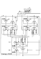
Disaggregation ROADMを制御するためには、コントローラ(SDNコントローラやNMS)がDisaggregation ROADMを構成する全装置及び構成装置同士の配線情報(接続状態)を登録情報としてデータベースに持つ必要がある。そのイメージを図1に示す。
しかし、ROADMの方路が増えるほどに構成装置の台数も増加し、配線情報も複雑で膨大な数となっていき、データベースへの登録が難しくなるという課題がある。
本発明は上記の点に鑑みてなされたものであり、分散型光伝送装置を構成する構成装置間の接続状態を動的に検出し、データベースに登録することを可能とする技術を提供することを目的とする。
開示の技術によれば、分散型光伝送装置を構成する構成装置間の接続状態をデータベースに登録する制御装置であって、
接続元の構成装置から光を出力させる設定を行う装置設定部と、
前記光を受信する側の各構成装置における各ポートの受光レベルを取得し、受光レベルが他のポートの受光レベルよりも高いポートを特定し、当該特定されたポートを有する構成装置と当該特定のポートを、前記接続元の構成装置の接続先として前記データベースに登録する登録処理部
を備えることを特徴とする制御装置が提供される。
接続元の構成装置から光を出力させる設定を行う装置設定部と、
前記光を受信する側の各構成装置における各ポートの受光レベルを取得し、受光レベルが他のポートの受光レベルよりも高いポートを特定し、当該特定されたポートを有する構成装置と当該特定のポートを、前記接続元の構成装置の接続先として前記データベースに登録する登録処理部
を備えることを特徴とする制御装置が提供される。
開示の技術によれば、分散型光伝送装置を構成する構成装置間の接続状態を動的に検出し、データベースに登録することを可能とする技術が提供される。
以下、図面を参照して本発明の実施の形態を説明する。以下で説明する実施の形態は一例に過ぎず、本発明が適用される実施の形態は、以下の実施の形態に限られるわけではない。以下の実施の形態では、分散型光伝送装置の例としてDisaggregation ROADMを挙げて説明しているが、本発明は、Disaggregation ROADMに限らず、他の種類の伝送装置にも適用可能である。
(実施の形態の概要)
本実施の形態では、Disaggregation ROADMを構成するWSS部(光スイッチ:Wavelength Selective Switch)とAMP部(光増幅装置)をコントローラから制御することで、WSS部同士の接続状態を自動検出し、データベースに登録する。
本実施の形態では、Disaggregation ROADMを構成するWSS部(光スイッチ:Wavelength Selective Switch)とAMP部(光増幅装置)をコントローラから制御することで、WSS部同士の接続状態を自動検出し、データベースに登録する。
図2を参照して自動検出処理の概要を説明する。図2には、コントローラ20と、Disaggregation ROADMを構成するAMP部1、WSS部2、WSS部3、AMP部4が示されている。
図2に示す例では、S1(ステップ1)において、コントローラ20がAMP部1の光増幅装置(AMP5)を有効化し、自然放出光を増幅して光源とするASE(Amplified Spontaneous Emission)光源を用いることで、接続されているWSS部2のWSS6へと光の入力を行う。S2において、コントローラ20は、WSS6のどのポートから光を出力するかを設定する。
S3において、コントローラ20は、WSS部3のWSS7おける全接続ポートの光レベルをモニターし受光を確認することで、WSS部同士の接続状態を検出する。本実施の形態では、ASEを利用することで特別な試験光装置なしに、WSSで受光を確認できる。
上記手順を全WSS部の全ポートに対して実施することでDisaggregation ROADMの内部接続状況をコントローラ20のデータベースに登録することができる。
WSS部は1xNのWSSをIN/Outの両系に持つ装置と、WSSをIN側にだけ持ちOUT側はSplitterを持つ2種類のパターンがある。本発明に係る技術により、いずれのパターンを用いる場合でも、Disaggregation ROADMのWSS部同士の接続状況の自動検出が可能である。
以下、実施の形態をより詳細に説明する。Route and SelectモデルのDisaggregation ROADMを使用する場合の例を第1の実施の形態として説明し、Broadcast and SelectモデルのDisaggregation ROADMを使用する場合の例を第2の実施の形態として説明する。なお、WSS部が1xNのWSSをIN/Outの両系に持つ構成がRoute and Selectモデルに対応し、WSSをIN側にだけ持ちOUT側はSplitterを持つ構成がBroadcast and Selectモデルに対応する。
(第1の実施の形態)
<システム構成>
図3に、第1の実施の形態におけるシステム構成図を示す。図3に示すように、本システムは、Disaggregation ROADM10とコントローラ20を備え、これらがネットワークで接続される構成を有する。また、データベース装置であるROADM内部接続状態DB21が備えられており、コントローラ20は当該ROADM内部接続状態DB21に対してデータの読み書きが可能である。ROADM内部接続状態DB21は、コントローラ20の内部に存在してもよいし、外部に存在してもよい。
<システム構成>
図3に、第1の実施の形態におけるシステム構成図を示す。図3に示すように、本システムは、Disaggregation ROADM10とコントローラ20を備え、これらがネットワークで接続される構成を有する。また、データベース装置であるROADM内部接続状態DB21が備えられており、コントローラ20は当該ROADM内部接続状態DB21に対してデータの読み書きが可能である。ROADM内部接続状態DB21は、コントローラ20の内部に存在してもよいし、外部に存在してもよい。
Disaggregation ROADM10は、WSS部110、210、310、AMP部120、220、320を有する。各AMP部は、入力側AMPと出力側AMPを備え、各WSS部は、入力側の1×NのWSSと出力側の1×NのWSSを備える。各WSSは1番からN番のポートを有する。なお、WSSは光スイッチの例である。AMPは光増幅装置の例である。
図4は、コントローラ20の機能構成図である。図4は、コントローラ20がROADM内部接続状態DB21を有する例を示している。
図4に示すとおり、コントローラ20は、ROADM内部接続状態DB21、Disaggregation ROADM10を構成する各構成装置に対する設定等を行う装置設定部22、ポートのモニター結果である受光レベルに基づいて配線情報の登録を行う登録処理部23、処理手順の制御等を行う制御部24を含む。なお、コントローラ20の動作の詳細は後述する。コントローラ20を制御装置と称してもよい。
コントローラ20は、例えば、コンピュータに、本実施の形態で説明する処理内容を記述したプログラムを実行させることにより実現可能である。
すなわち、コントローラ20は、コンピュータに内蔵されるCPUやメモリ等のハードウェア資源を用いて、コントローラ20で実施される処理に対応するプログラムを実行することによって実現することが可能である。上記プログラムは、コンピュータが読み取り可能な記録媒体(可搬メモリ等)に記録して、保存したり、配布したりすることが可能である。また、上記プログラムをインターネットや電子メール等、ネットワークを通して提供することも可能である。
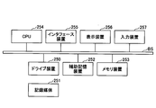
図5は、本実施の形態における上記コンピュータのハードウェア構成例を示す図である。図5のコンピュータは、それぞれバスBで相互に接続されているドライブ装置250、補助記憶装置252、メモリ装置253、CPU254、インタフェース装置255、表示装置256、及び入力装置257等を有する。
当該コンピュータでの処理を実現するプログラムは、例えば、CD-ROM又はメモリカード等の記録媒体251によって提供される。プログラムを記憶した記録媒体251がドライブ装置250にセットされると、プログラムが記録媒体251からドライブ装置250を介して補助記憶装置252にインストールされる。但し、プログラムのインストールは必ずしも記録媒体251より行う必要はなく、ネットワークを介して他のコンピュータよりダウンロードするようにしてもよい。補助記憶装置252は、インストールされたプログラムを格納すると共に、必要なファイルやデータ等を格納する。
メモリ装置253は、プログラムの起動指示があった場合に、補助記憶装置252からプログラムを読み出して格納する。CPU254は、メモリ装置253に格納されたプログラムに従って、コントローラ20に係る機能を実現する。インタフェース装置255は、ネットワークに接続するためのインタフェースとして用いられる。表示装置256はプログラムによるGUI(Graphical User Interface)等を表示する。入力装置257はキーボード及びマウス、ボタン、又はタッチパネル等で構成され、様々な操作指示を入力させるために用いられる。
<システムの動作>
次に、図6に示すフローチャートの手順に沿って、図3に示した第1の実施の形態におけるシステムの動作を説明する。
次に、図6に示すフローチャートの手順に沿って、図3に示した第1の実施の形態におけるシステムの動作を説明する。
S101において、Disaggregation ROADM10を構成するWSS部110、210、310とAMP部120、220、320のセット及びWSS部のポート数をコントローラ20に入力することで、ROADM内部接続状態DB21に構成装置情報を持たせる。ROADM内部接続状態DB21に格納される構成装置情報の例を図7に示す。
S102において、コントローラ20の装置設定部22は、登録されたAMP部のうちの1台のAMP部120の入力側のAMP121を有効にする。これによりASEが増幅され、有効化したAMP部120とセットで登録されているWSS部110の入力側のWSS111に光が入力される。
S103において、コントローラ20の装置設定部22は、WSS111の1番ポートに特定の波長を通す設定を投入する。これによりWSS111の1番ポートから光が出力される。
S104において、コントローラ20の登録処理部23は、設定を投入したWSS部110以外の全てのWSS部210、310のWSS212、312の全ポートのモニター出力を取得し、受光レベルが他のポートに比べ明確に高いポートを特定し、当該ポートをROADM内部接続状態DB21に接続元WSS111の接続元ポート1の接続先WSS・接続先WSSポートとして登録する。受光レベルが明確に高いポートがなかった場合は接続先無しとしてNullを登録する。
なお、受光レベルが他のポートに比べ明確に高いポートとは、例えば、受光レベルが最も高いポートであって、その受光レベルと、受光レベルが最も低いポートの受光レベルとの差分が所定の閾値以上のポートである。ただし、これは一例に過ぎない。
S105において、コントローラ20の装置設定部22は、WSS111に投入した設定を削除する。これによりWSS111の1番ポートから光が出力されなくなる。
次に、制御部24の制御により、S103におけるWSS111の設定するポート番号を2からN番ポートまで順番に変更しながらS103~105を繰り返し実行する(S106)。これによりWSS111の全ポートの接続先の情報をROADM内部接続状態DB21に登録できる。
S107において、コントローラ20の装置設定部22は、S102で有効にしたAMP121の設定を無効にする。コントローラ20は、制御部24の制御により、S102~S107をまだ実行していないWSS部210、310のそれぞれに対し、S102~S107を実行する(S108)。
以上の処理の結果として得られるWSSの接続先ポート情報の例を図7に示す。
(第2の実施の形態)
<システム構成>
図8に、第2の実施の形態におけるシステム構成図を示す。図8に示すように、Disaggregation ROADM10とコントローラ20を備え、これらがネットワークで接続される構成を有する。また、データベース装置であるROADM内部接続状態DB21が備えられており、コントローラ20は当該ROADM内部接続状態DB21に対してデータの読み書きが可能である。ROADM内部接続状態DB21は、コントローラ20の内部に存在してもよいし、外部に存在してもよい。
<システム構成>
図8に、第2の実施の形態におけるシステム構成図を示す。図8に示すように、Disaggregation ROADM10とコントローラ20を備え、これらがネットワークで接続される構成を有する。また、データベース装置であるROADM内部接続状態DB21が備えられており、コントローラ20は当該ROADM内部接続状態DB21に対してデータの読み書きが可能である。ROADM内部接続状態DB21は、コントローラ20の内部に存在してもよいし、外部に存在してもよい。
第2の実施の形態では、Disaggregation ROADM10内部の構成が第1の実施の形態と異なる。具体的には、図3、図8に示すとおり、1×NのWSS111、211、311がそれぞれ1×NのSplittter111、211、311になる。この点以外は第1の実施の形態と同じである。
コントローラ20の機能構成(図4)、コントローラ20がコンピュータとプログラムで実現できる点も第1の実施の形態と同じである。
<システムの動作>
次に、図9に示すフローチャートの手順に沿って、第2の実施の形態におけるシステムの動作を説明する。
次に、図9に示すフローチャートの手順に沿って、第2の実施の形態におけるシステムの動作を説明する。
S201において、Disaggregation ROADM10を構成するWSS部110、210、310とAMP部120、220、320のセット及びWSS部のポート数をコントローラ20に入力することで、ROADM内部接続状態DB21に構成装置情報を持たせる。ROADM内部接続状態DB21に格納される構成装置情報の例を図10に示す。
S202において、コントローラ20の装置設定部22は、登録されたAMP部のうちの1台のAMP部120の入力側のAMP121を有効にする。これによりASEが増幅され、有効化したAMP部とセットで登録されているWSS部110の入力側のSplitter111に光が入力され、Splitter111の全ポートより光が出力される。
S203において、コントローラ20の登録処理部23は、設定を投入したWSS部110以外の全てのWSS部210、310のWSS212、312の全ポートのモニター出力を取得し、受光レベルが他のポートに比べ明確に高いポートを特定し、当該ポートをROADM内部接続状態DB21に接続元WSS111の接続先WSS・接続先WSSポートとして登録する。
受光レベルが他のポートに比べ明確に高いポートとは、例えば、そのポートの受光レベルと、受光レベルが最も低いポートの受光レベルとの差分が所定の閾値以上のポートである。ただし、これは一例に過ぎない。
受光レベルが明確に高いポートが複数ある場合は当該複数のポートを全部、接続先WSS・接続先WSSポートとして登録する。受光レベルが明確に高いポートがなかった場合は接続先無しとしてNullを登録する。
S204において、コントローラ20の装置設定部22は、S202で有効にしたAMP121の設定を無効にする。
コントローラ20は、S202~S204をまだ実行していないWSS部210、310のそれぞれに対して、S202~S204を実行する(S205)。
以上の処理の結果として得られるWSSの接続先ポート情報の例を図10に示す。
(実施の形態の効果)
本発明の実施の形態により、Disaggregation ROADMをコントローラから制御する際に必要となる内部接続情報を自動的に検出し、登録することが可能となる。この技術を用いることでコントローラへの人手での情報登録が不要になる。また、この技術は、人手での登録情報が間違ってないかの確認テストとしても利用することが可能である。
本発明の実施の形態により、Disaggregation ROADMをコントローラから制御する際に必要となる内部接続情報を自動的に検出し、登録することが可能となる。この技術を用いることでコントローラへの人手での情報登録が不要になる。また、この技術は、人手での登録情報が間違ってないかの確認テストとしても利用することが可能である。
また、本発明の実施の形態では、自然放出光を利用することで試験光を発する特別な装置なしに光を出力させることが可能である。
(実施の形態のまとめ)
本明細書には、少なくとも下記の事項が記載されている。
(第1項)
分散型光伝送装置を構成する構成装置間の接続状態をデータベースに登録する制御装置であって、
接続元の構成装置から光を出力させる設定を行う装置設定部と、
前記光を受信する側の各構成装置における各ポートの受光レベルを取得し、受光レベルが他のポートの受光レベルよりも高いポートを特定し、当該特定されたポートを有する構成装置と当該特定のポートを、前記接続元の構成装置の接続先として前記データベースに登録する登録処理部
を備えることを特徴とする制御装置。
本明細書には、少なくとも下記の事項が記載されている。
(第1項)
分散型光伝送装置を構成する構成装置間の接続状態をデータベースに登録する制御装置であって、
接続元の構成装置から光を出力させる設定を行う装置設定部と、
前記光を受信する側の各構成装置における各ポートの受光レベルを取得し、受光レベルが他のポートの受光レベルよりも高いポートを特定し、当該特定されたポートを有する構成装置と当該特定のポートを、前記接続元の構成装置の接続先として前記データベースに登録する登録処理部
を備えることを特徴とする制御装置。
第1及び第2の実施の形態におけるDisaggregation ROADM10、及びコントローラ20はそれぞれ、分散型光伝送装置、及び制御装置の例である。また、受光レベルが他のポートの受光レベルよりも高いポートを特定することは、例えば、前述したように、受光レベルが他のポートの受光レベルよりも明確に高いポートを特定することである。
(第2項)
前記接続元の構成装置は光スイッチであり、前記装置設定部は、当該光スイッチにおける1つのポートから光を出力させる設定を行い、
前記登録処理部は、前記特定されたポートを有する構成装置と前記特定のポートを、前記光スイッチの前記1つのポートの接続先として前記データベースに登録し、
前記光スイッチにおけるポートを変更しながら前記装置設定部による処理と前記登録処理部による処理を繰り返し実行する
第1項に記載の制御装置。
(第3項)
前記接続元の構成装置は光スプリッタであり、前記装置設定部による設定により、当該光スプリッタの全ポートから光が出力される
第1項に記載の制御装置。
(第4項)
前記装置設定部は、前記接続元の構成装置に接続される光増幅装置を有効化することにより、自然放出光を増幅して得られた光が前記接続元の構成装置に入力されるようにする
第1項ないし第3項のうちいずれか1項に記載の制御装置。
(第5項)
分散型光伝送装置を構成する構成装置間の接続状態をデータベースに登録する制御装置が実行する接続状態登録方法であって、
接続元の構成装置から光を出力させる設定を行う装置設定ステップと、
前記光を受信する側の各構成装置における各ポートの受光レベルを取得し、受光レベルが他のポートの受光レベルよりも高いポートを特定し、当該特定されたポートを有する構成装置と当該特定のポートを、前記接続元の構成装置の接続先として前記データベースに登録する登録処理ステップと
を備えることを特徴とする接続状態登録方法。
(第6項)
コンピュータを、第1項ないし第4項のうちいずれか1項に記載の前記制御装置における各部として機能させるためのプログラム。
(第2項)
前記接続元の構成装置は光スイッチであり、前記装置設定部は、当該光スイッチにおける1つのポートから光を出力させる設定を行い、
前記登録処理部は、前記特定されたポートを有する構成装置と前記特定のポートを、前記光スイッチの前記1つのポートの接続先として前記データベースに登録し、
前記光スイッチにおけるポートを変更しながら前記装置設定部による処理と前記登録処理部による処理を繰り返し実行する
第1項に記載の制御装置。
(第3項)
前記接続元の構成装置は光スプリッタであり、前記装置設定部による設定により、当該光スプリッタの全ポートから光が出力される
第1項に記載の制御装置。
(第4項)
前記装置設定部は、前記接続元の構成装置に接続される光増幅装置を有効化することにより、自然放出光を増幅して得られた光が前記接続元の構成装置に入力されるようにする
第1項ないし第3項のうちいずれか1項に記載の制御装置。
(第5項)
分散型光伝送装置を構成する構成装置間の接続状態をデータベースに登録する制御装置が実行する接続状態登録方法であって、
接続元の構成装置から光を出力させる設定を行う装置設定ステップと、
前記光を受信する側の各構成装置における各ポートの受光レベルを取得し、受光レベルが他のポートの受光レベルよりも高いポートを特定し、当該特定されたポートを有する構成装置と当該特定のポートを、前記接続元の構成装置の接続先として前記データベースに登録する登録処理ステップと
を備えることを特徴とする接続状態登録方法。
(第6項)
コンピュータを、第1項ないし第4項のうちいずれか1項に記載の前記制御装置における各部として機能させるためのプログラム。
以上、本実施の形態について説明したが、本発明はかかる特定の実施形態に限定されるものではなく、特許請求の範囲に記載された本発明の要旨の範囲内において、種々の変形・変更が可能である。
10 Disaggregation ROADM
21 ROADM内部接続状態DB
22 装置設定部
23 登録処理部
24 制御部
250 ドライブ装置
251 記録媒体
252 補助記憶装置
253 メモリ装置
254 CPU
255 インターフェース装置
256 表示装置
257 入力装置
21 ROADM内部接続状態DB
22 装置設定部
23 登録処理部
24 制御部
250 ドライブ装置
251 記録媒体
252 補助記憶装置
253 メモリ装置
254 CPU
255 インターフェース装置
256 表示装置
257 入力装置
Claims (6)
- 分散型光伝送装置を構成する構成装置間の接続状態をデータベースに登録する制御装置であって、
接続元の構成装置から光を出力させる設定を行う装置設定部と、
前記光を受信する側の各構成装置における各ポートの受光レベルを取得し、受光レベルが他のポートの受光レベルよりも高いポートを特定し、当該特定されたポートを有する構成装置と当該特定のポートを、前記接続元の構成装置の接続先として前記データベースに登録する登録処理部と
を備えることを特徴とする制御装置。 - 前記接続元の構成装置は光スイッチであり、前記装置設定部は、当該光スイッチにおける1つのポートから光を出力させる設定を行い、
前記登録処理部は、前記特定されたポートを有する構成装置と前記特定のポートを、前記光スイッチの前記1つのポートの接続先として前記データベースに登録し、
前記光スイッチにおけるポートを変更しながら前記装置設定部による処理と前記登録処理部による処理を繰り返し実行する
請求項1に記載の制御装置。 - 前記接続元の構成装置は光スプリッタであり、前記装置設定部による設定により、当該光スプリッタの全ポートから光が出力される
請求項1に記載の制御装置。 - 前記装置設定部は、前記接続元の構成装置に接続される光増幅装置を有効化することにより、自然放出光を増幅して得られた光が前記接続元の構成装置に入力されるようにする
請求項1ないし3のうちいずれか1項に記載の制御装置。 - 分散型光伝送装置を構成する構成装置間の接続状態をデータベースに登録する制御装置が実行する接続状態登録方法であって、
接続元の構成装置から光を出力させる設定を行う装置設定ステップと、
前記光を受信する側の各構成装置における各ポートの受光レベルを取得し、受光レベルが他のポートの受光レベルよりも高いポートを特定し、当該特定されたポートを有する構成装置と当該特定のポートを、前記接続元の構成装置の接続先として前記データベースに登録する登録処理ステップと
を備えることを特徴とする接続状態登録方法。 - コンピュータを、請求項1ないし4のうちいずれか1項に記載の前記制御装置における各部として機能させるためのプログラム。
Priority Applications (1)
| Application Number | Priority Date | Filing Date | Title |
|---|---|---|---|
| US17/291,485 US11522614B2 (en) | 2018-11-14 | 2019-11-11 | Control apparatus, connection status registration method and program |
Applications Claiming Priority (2)
| Application Number | Priority Date | Filing Date | Title |
|---|---|---|---|
| JP2018214204A JP7183719B2 (ja) | 2018-11-14 | 2018-11-14 | 制御装置、接続状態登録方法、及びプログラム |
| JP2018-214204 | 2018-11-14 |
Publications (1)
| Publication Number | Publication Date |
|---|---|
| WO2020100822A1 true WO2020100822A1 (ja) | 2020-05-22 |
Family
ID=70731839
Family Applications (1)
| Application Number | Title | Priority Date | Filing Date |
|---|---|---|---|
| PCT/JP2019/044162 Ceased WO2020100822A1 (ja) | 2018-11-14 | 2019-11-11 | 制御装置、接続状態登録方法、及びプログラム |
Country Status (3)
| Country | Link |
|---|---|
| US (1) | US11522614B2 (ja) |
| JP (1) | JP7183719B2 (ja) |
| WO (1) | WO2020100822A1 (ja) |
Families Citing this family (1)
| Publication number | Priority date | Publication date | Assignee | Title |
|---|---|---|---|---|
| JP7435726B2 (ja) * | 2020-02-25 | 2024-02-21 | 日本電信電話株式会社 | 伝送装置間接続登録装置、伝送装置間接続登録方法及びプログラム |
Citations (5)
| Publication number | Priority date | Publication date | Assignee | Title |
|---|---|---|---|---|
| JP2008099191A (ja) * | 2006-10-16 | 2008-04-24 | Kddi Corp | インテリジェントパッチパネル管理制御方式 |
| JP2009177433A (ja) * | 2008-01-23 | 2009-08-06 | Nec Corp | 光伝送路の接続状態監視方法およびシステム |
| JP2012182665A (ja) * | 2011-03-01 | 2012-09-20 | Nec Corp | 光ノード装置、光ノード装置の接続確認方法、及びプログラム |
| JP2012205155A (ja) * | 2011-03-25 | 2012-10-22 | Fujitsu Ltd | 光通信装置および光通信方法 |
| US20170353246A1 (en) * | 2016-06-07 | 2017-12-07 | Ciena Corporation | Software programmable flexible and dynamic optical transceivers |
Family Cites Families (3)
| Publication number | Priority date | Publication date | Assignee | Title |
|---|---|---|---|---|
| JP4427463B2 (ja) * | 2004-03-30 | 2010-03-10 | 富士通株式会社 | 光配線切替装置及びその管理制御装置 |
| JP5724416B2 (ja) * | 2011-02-03 | 2015-05-27 | 富士通株式会社 | 光伝送装置および光伝送システム |
| US9444549B2 (en) * | 2014-04-21 | 2016-09-13 | Arris Enterprises, Inc. | Systems and methods for burst detection in a CATV network |
-
2018
- 2018-11-14 JP JP2018214204A patent/JP7183719B2/ja active Active
-
2019
- 2019-11-11 WO PCT/JP2019/044162 patent/WO2020100822A1/ja not_active Ceased
- 2019-11-11 US US17/291,485 patent/US11522614B2/en active Active
Patent Citations (5)
| Publication number | Priority date | Publication date | Assignee | Title |
|---|---|---|---|---|
| JP2008099191A (ja) * | 2006-10-16 | 2008-04-24 | Kddi Corp | インテリジェントパッチパネル管理制御方式 |
| JP2009177433A (ja) * | 2008-01-23 | 2009-08-06 | Nec Corp | 光伝送路の接続状態監視方法およびシステム |
| JP2012182665A (ja) * | 2011-03-01 | 2012-09-20 | Nec Corp | 光ノード装置、光ノード装置の接続確認方法、及びプログラム |
| JP2012205155A (ja) * | 2011-03-25 | 2012-10-22 | Fujitsu Ltd | 光通信装置および光通信方法 |
| US20170353246A1 (en) * | 2016-06-07 | 2017-12-07 | Ciena Corporation | Software programmable flexible and dynamic optical transceivers |
Non-Patent Citations (1)
| Title |
|---|
| ODA, S. ET AL.: "A learning living network with open ROADMs", JOURNAL OF LIGHTWAVE TECHNOLOG Y, vol. 35, no. 8, April 2017 (2017-04-01), pages 1350 - 1356, XP011645580, DOI: 10.1109/JLT.2017.2660540 * |
Also Published As
| Publication number | Publication date |
|---|---|
| JP2020088404A (ja) | 2020-06-04 |
| JP7183719B2 (ja) | 2022-12-06 |
| US20220006529A1 (en) | 2022-01-06 |
| US11522614B2 (en) | 2022-12-06 |
Similar Documents
| Publication | Publication Date | Title |
|---|---|---|
| US11190407B2 (en) | Internet of things device discovery and configuration | |
| KR102175193B1 (ko) | 자동 장치 탐지를 위한 시스템 및 방법 | |
| JP5918376B2 (ja) | 光配信ネットワーク管理方法及びシステム | |
| US10305749B2 (en) | Low latency flow cleanup of openflow configuration changes | |
| US20210117908A1 (en) | Graph views and models for representing networks and associated inventory | |
| US20150172192A1 (en) | Software-defined networking physical controller | |
| US20080192654A1 (en) | Method, Apparatus, and Computer Program Product for Implementing Infiniband Network Topology Simplification | |
| US20180034780A1 (en) | Generation of asset data used in creating testing events | |
| US10797791B2 (en) | Detecting a transceiver using a noise optical signal | |
| US11431575B2 (en) | Network system, topology management method, and program | |
| WO2020100822A1 (ja) | 制御装置、接続状態登録方法、及びプログラム | |
| US20220345215A1 (en) | Real-time health monitoring in an all-photonics network | |
| US11595122B2 (en) | Identifying link fingerprint anomalies in real-time in an all-photonics network | |
| US20210377129A1 (en) | Network building apparatus, network building method, non-transitory computer readable medium storing program | |
| US11528188B2 (en) | Graphically managing a networking device configuration | |
| US11025361B2 (en) | System and method for configuring photonic components using photonic abstraction interface | |
| KR101681154B1 (ko) | 데이터 수집기 구축 방법, 이를 수행하는 데이터 수집기 구축 서버 및 이를 저장하는 기록매체 | |
| US20230216891A1 (en) | Security group differencing utility to assess changes and adoption risks | |
| US11595124B2 (en) | Path management for tiered service level agreements in an all-photonics network | |
| US11595123B2 (en) | Identifying optimal paths in an all-photonics network | |
| US11388493B1 (en) | Secure and attested all-photonics network | |
| US11677463B2 (en) | Infrastructure integrity and attestation of an all-photonics network | |
| US11687476B2 (en) | Management apparatus, management system, management method, and non-transitory computer readable medium | |
| US20250227019A1 (en) | Network monitoring system, network monitoring method, and recording medium | |
| US20240414158A1 (en) | Network configuration device, information system, network configuration method, and recording medium |
Legal Events
| Date | Code | Title | Description |
|---|---|---|---|
| 121 | Ep: the epo has been informed by wipo that ep was designated in this application |
Ref document number: 19883400 Country of ref document: EP Kind code of ref document: A1 |
|
| NENP | Non-entry into the national phase |
Ref country code: DE |
|
| 122 | Ep: pct application non-entry in european phase |
Ref document number: 19883400 Country of ref document: EP Kind code of ref document: A1 |