WO2020100370A1 - 光脳機能計測装置用ファントム装置 - Google Patents
光脳機能計測装置用ファントム装置 Download PDFInfo
- Publication number
- WO2020100370A1 WO2020100370A1 PCT/JP2019/032892 JP2019032892W WO2020100370A1 WO 2020100370 A1 WO2020100370 A1 WO 2020100370A1 JP 2019032892 W JP2019032892 W JP 2019032892W WO 2020100370 A1 WO2020100370 A1 WO 2020100370A1
- Authority
- WO
- WIPO (PCT)
- Prior art keywords
- filter
- light
- light source
- brain function
- function measuring
- Prior art date
- Legal status (The legal status is an assumption and is not a legal conclusion. Google has not performed a legal analysis and makes no representation as to the accuracy of the status listed.)
- Ceased
Links
Images






Classifications
-
- A—HUMAN NECESSITIES
- A61—MEDICAL OR VETERINARY SCIENCE; HYGIENE
- A61B—DIAGNOSIS; SURGERY; IDENTIFICATION
- A61B10/00—Instruments for taking body samples for diagnostic purposes; Other methods or instruments for diagnosis, e.g. for vaccination diagnosis, sex determination or ovulation-period determination; Throat striking implements
-
- G—PHYSICS
- G01—MEASURING; TESTING
- G01N—INVESTIGATING OR ANALYSING MATERIALS BY DETERMINING THEIR CHEMICAL OR PHYSICAL PROPERTIES
- G01N21/00—Investigating or analysing materials by the use of optical means, i.e. using sub-millimetre waves, infrared, visible or ultraviolet light
- G01N21/01—Arrangements or apparatus for facilitating the optical investigation
-
- G—PHYSICS
- G01—MEASURING; TESTING
- G01N—INVESTIGATING OR ANALYSING MATERIALS BY DETERMINING THEIR CHEMICAL OR PHYSICAL PROPERTIES
- G01N21/00—Investigating or analysing materials by the use of optical means, i.e. using sub-millimetre waves, infrared, visible or ultraviolet light
- G01N21/17—Systems in which incident light is modified in accordance with the properties of the material investigated
Definitions
- the present invention relates to a phantom device for an optical brain function measuring device, and particularly to a phantom device for an optical brain function measuring device provided with a filter having a predetermined absorption frequency distribution.
- a phantom device for an optical brain function measuring device including a filter having a predetermined absorption frequency distribution is known.
- Such a phantom device for an optical brain function measuring device is disclosed in, for example, Japanese Patent Laid-Open No. 2009-195387.
- the inspection phantom device of the biological optical measurement device disclosed in JP 2009-195387 A is provided with a main scatterer, an auxiliary scatterer, a light absorber (filter), and a driving device.
- Each of the main scatterer and the auxiliary scatterer is composed of a rectangular resin plate in which a resin in which powder that reflects light is evenly mixed is molded on a flat plate. Further, each of the main scatterer and the auxiliary scatterer has a light-transmitting property and scatters the light incident therein. Further, the auxiliary scatterer faces the surface on one side of the main scatterer at a predetermined interval.
- the light absorber is controlled by the drive device and is configured to move between the main scatterer and the auxiliary scatterer.
- a plurality of irradiation probes that irradiate light and a plurality of detections that detect light are provided on the other surface of the main scatterer.
- a probe is provided.
- the light emitted from the irradiation probe is emitted from the surface on one side of the main scatterer, part of which is absorbed by the light absorber, and the remaining part of which is incident on the auxiliary scatterer.
- the light incident on the auxiliary scatterer is diffused in the auxiliary scatterer, and part of the light is incident on the main scatterer again. Then, the light incident on the main scatterer again is detected by the detection probe.
- the light emitted from the main scatterer is not specified in JP-A-2009-195387. Is believed to be uniformly attenuated regardless of the frequency of light by being absorbed by the light absorber (filter).
- the human body (brain) contains a plurality of biological substances having different absorption frequency distributions (absorption spectra) for light.
- the concentrations (amounts) of one biological substance (hereinafter, first biological substance) and the other biological substance (hereinafter, second biological substance) among the plurality of biological substances are different from each other according to brain activity. It may change at different rates.
- the concentration (amount) of the first biological substance and the second biological substance are used.
- the concentration (amount) of the first biological substance and the second biological substance are used.
- the present invention has been made in order to solve the above problems, and one object of the present invention is to accurately test an optical brain function measuring device by accurately simulating brain activity. It is possible to provide a phantom device for a possible optical brain function measuring device.
- a phantom device for an optical brain function measuring device includes a light source unit that emits light and a detecting unit that detects light from the light source unit.
- a phantom device for an optical brain function measuring device used in the device wherein light from a light source unit is irradiated, a first filter having a first absorption frequency distribution with respect to the light, and light from the light source unit are irradiated.
- the first absorption frequency distribution of the first filter is different from the first absorption frequency distribution of the first filter, and at least part of the first absorption filter overlaps with the first filter when viewed from the direction in which the optical axis of the light from the light source extends.
- a second filter provided in such a manner that the first filter and the second filter are configured to be movable relative to the light source unit and the detection unit, and relative to the light source unit and the detection unit.
- the light absorptance is different for each part along the moving direction.
- the first filter and the second filter are arranged to emit light in each part along the moving direction relative to the light source part and the detection part. Absorption rate is different. Accordingly, the amount of light absorbed by each of the first filter and the second filter can be changed by moving the first filter and the second filter relative to the light source unit and the detection unit. Further, by controlling the movement of the first filter and the second filter, it is possible to easily change the amount of light absorbed by each of the first filter and the second filter at different change rates.
- the optical brain function measuring device can be properly tested by accurately simulating the brain activity.
- the actual brain activity can be accurately simulated by the phantom device for optical brain function measuring device, it is necessary to compare the test results obtained by using the phantom device with the actual brain data (waveform). Thus, it is possible to determine whether or not the optical brain function measuring device is normal. As a result, the inspection results obtained using the phantom device in each device and the actual results obtained by comparing the measurement data in each device between devices having different characteristics (for example, the number of wavelengths of light to be irradiated) are different from each other. By comparing with the brain data (waveform), the performance of each device can be evaluated more accurately.
- each of the first filter and the second filter is irradiated with near-infrared light from the light source unit, and the first filter absorbs the first absorption light.
- the frequency distribution is configured to be substantially equal to the absorption frequency distribution of oxygenated hemoglobin
- the second filter is configured such that the second absorption frequency distribution is substantially equal to the absorption frequency distribution of the deoxygenated hemoglobin filter.
- a moving mechanism that relatively moves the first filter and the second filter with respect to the light source unit and the detecting unit, and control that controls the moving mechanism.
- a control unit that controls the moving mechanism in a state where light is applied to a portion where the first filter and the second filter overlap each other, and
- Each of the first filter and the second filter is configured to relatively move along a direction orthogonal to the direction in which the optical axis extends.
- the first filter is configured such that the absorptance of light continuously changes along the first direction in the plane orthogonal to the direction in which the optical axis extends
- the second filter is the first filter.
- the light absorptance is configured to continuously change along the direction of 1
- the control unit controls the moving mechanism to cause the light source unit and the detection unit to perform the first filter and the second filter.
- the filter is configured to move relatively along the first direction. According to this structure, a direction in which the first filter and the second filter move relative to the light source unit and the detection unit, and a direction in which the light absorption rate of each of the first filter and the second filter changes Are available. As a result, the amount of light absorbed by the first filter and the second filter can be easily changed by moving the first filter and the second filter relative to the light source unit and the detection unit.
- the light absorption rate of each of the first filter and the second filter changes continuously, the light absorption rate changes more finely (accurately) than the case where the light absorption rate changes stepwise (discontinuously). Can simulate brain activity.
- the moving mechanism is the light source unit and the detection unit.
- the first moving mechanism and the second moving mechanism are individually controlled so that the first filter and the second filter are independently moved.
- the first moving mechanism and the second moving mechanism independently move each of the first filter and the second filter, thereby absorbing the light by the first filter and absorbing the light by the second filter. It is possible to facilitate adjusting the quantity and the quantity separately.
- the first filter continuously changes the absorptance of light along a first direction in a plane orthogonal to the direction in which the optical axis extends.
- the second filter is configured to continuously change the absorptance of light along a second direction intersecting the first direction on a plane orthogonal to the direction in which the optical axis extends.
- the control unit controls the moving mechanism so that the first filter and the second filter are relatively moved with respect to the light source unit and the detection unit along a plane orthogonal to the direction in which the optical axis extends. Is configured.
- the optical axis is extended by intersecting the first direction in which the light absorption rate changes in the first filter and the second direction in which the light absorption rate changes in the second filter.
- the combination of the absorptance of light in the first filter and the absorptance of light in the second filter in a portion where the first filter and the second filter overlap when viewed from the direction is two-dimensionally (first direction and first filter). It can be changed for each in-plane coordinate with the two directions).
- control unit is configured to control the moving mechanism to integrally move the first filter and the second filter.
- the control load of the control unit is reduced as compared with the case where the first filter and the second filter are individually moved. can do.
- the control unit controls the moving mechanism to move the first filter and the second filter relative to the light source unit and the detection unit. By doing so, control is performed to generate a plurality of waveforms based on changes in the amount of light absorbed by each of the first filter and the second filter. According to this structure, by generating a plurality of waveforms, brain activities having a plurality of symptoms can be simulated.
- the brain activity of a plurality of symptoms is automatically discriminated. be able to.
- a reflection part that reflects light from the light source part toward the detection part is further provided, and each of the first filter and the second filter is a light source part. And disposed between the detection unit and the reflection unit.
- the measurement is performed by detecting the light emitted from the device attached to the brain and reflected in the brain by the device. Therefore, each of the first filter and the second filter is arranged between the light source unit, the detection unit, and the reflection unit, so that the condition (composition) close to that of an actual brain examination using the optical brain function measuring device is provided. ) Can be inspected.
- each of the first filter and the second filter includes a color filter, and each part along a moving direction relative to the light source part and the detection part. Due to the different shades of color, the light absorptance is different for each part along the relative movement direction with respect to the light source part and the detection part. According to this structure, it is possible to easily simulate actual brain activity by using the color filter without using a biological substance.
- each of the first filter and the second filter has a thickness in a direction in which an optical axis of light from the light source unit extends with respect to the light source unit and the detection unit.
- the light absorptance is configured to differ depending on the portions along the relative movement direction with respect to the light source section and the detection section. According to this structure, the light absorptance of each of the first filter and the second filter can be easily adjusted only by adjusting the thickness without adjusting the density of the color.
- the phantom device for an optical brain function measuring device is preferably arranged alongside the first filter and the second filter in the direction in which the optical axis of the light from the light source unit extends to attenuate the intensity of the light. It further comprises a third filter. According to this structure, the attenuation of the light in the whole brain can be simulated by the third filter, so that the brain activity can be simulated more accurately.
- the optical brain function measuring device can be properly tested by accurately simulating the brain activity as described above.
- FIG. 3 is a plan view of an oxygenated hemoglobin filter and a deoxygenated hemoglobin filter of the phantom device according to the first embodiment.
- FIG. 3 is a perspective view of an oxygenated hemoglobin filter and a deoxygenated hemoglobin filter of the phantom device according to the first embodiment.
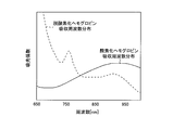
- FIG. 4 is a diagram showing absorption frequency distributions of near infrared light for each part in the X direction of the oxygenated hemoglobin filter and the deoxygenated hemoglobin filter of the phantom device according to the first embodiment.
- FIG. 6 (A) is a diagram showing the absorption frequency distribution of the oxygenated hemoglobin filter.
- FIG. 6 (B) is a diagram showing the absorption frequency distribution of the deoxygenated hemoglobin filter.) It is a figure which shows the waveform of the value calculated as the hemoglobin density
- FIG. 8 is a perspective view of an oxygenated hemoglobin filter and a deoxygenated hemoglobin filter of the phantom device according to the second embodiment. It is a figure showing an example of movement of an oxygenated hemoglobin filter and a deoxygenated hemoglobin filter of a phantom device by a 2nd embodiment.
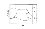
- FIG. 11 is a diagram showing a waveform of a value calculated as a hemoglobin concentration generated when the movement shown in FIG. 10 is performed. It is a figure which shows the structure of the phantom apparatus by the 1st modification of 1st Embodiment.
- FIG. 9 is a perspective view showing configurations of an oxygenated hemoglobin filter and a deoxygenated hemoglobin filter according to a second modification of the first embodiment.
- the phantom device 10 is a phantom device used in the optical brain function measuring device 100 that performs optical measurement (brain function measurement) by near infrared spectroscopy (NIRS).
- the phantom device 10 is an example of the “phantom device for optical brain function measuring device” in the claims.
- the optical brain function measuring device 100 includes an optical measuring unit 1 and a control unit 2.
- the optical brain function measuring device 100 includes a light transmitting fiber 3 and a light receiving fiber 4. Further, the optical brain function measuring device 100 has a function of measuring the brain activity of a subject (subject) using the light transmitting fiber 3 and the light receiving fiber 4 connected via the optical fiber 5.
- the light transmitting fiber 3 and the light receiving fiber 4 are examples of the “light source unit” and the “detection unit” in the claims, respectively.
- the light transmitting fiber 3 and the light receiving fiber 4 of the optical brain function measuring apparatus 100 are arranged at predetermined positions on the head surface of the subject by being attached to the probe fixing holder 6 attached to the subject's head. To be done. Then, the optical brain function measuring device 100 irradiates the measuring light in the wavelength region of the near-infrared light emitted from the light transmitting fiber 3 and makes the measuring light reflected in the head of the subject enter the light receiving fiber 4 for detection. By doing so, the intensity of the measurement light (amount of received light) is acquired. It is possible to acquire changes in the hemoglobin amount (oxygenated hemoglobin, deoxygenated hemoglobin, and total hemoglobin) associated with brain activity based on the acquired intensity of the measurement light.
- the hemoglobin amount oxygenated hemoglobin, deoxygenated hemoglobin, and total hemoglobin
- the optical brain function measuring apparatus 100 can non-invasively acquire changes in hemoglobin amount due to brain activity, that is, changes in blood flow amount and activation state of oxygen metabolism.
- the brain activity is measured at each measurement point formed by the pair of the light transmitting fiber 3 and the light receiving fiber 4.
- the measurement data is acquired as a relative hemoglobin change amount in the task period with respect to the rest period in the brain function measurement.
- the near infrared light is an example of “light” in the claims.
- the control unit 2 analyzes the measurement data transmitted from the optical measurement unit 1.
- the control unit 2 includes a display unit 2a including a liquid crystal display or the like.
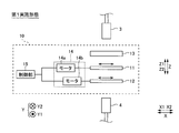
- FIG. 2 (Configuration of phantom device) As shown in FIG. 2, when the optical brain function measuring apparatus 100 is inspected by the phantom device 10, the light transmitting fiber 3 and the light receiving fiber 4 are linearly arranged so as to face each other.
- the direction in which the light transmitting fiber 3 and the light receiving fiber 4 are arranged is the Z direction in the first embodiment.
- the light transmitting fiber 3 is arranged on the Z1 direction side with respect to the light receiving fiber 4. Note that, in FIG. 2, the optical measurement unit 1 and the control unit 2 are not shown for simplification.
- the phantom device 10 includes an oxygenated hemoglobin filter 11, a deoxygenated hemoglobin filter 12, and an ND (Neutral Density) filter 13.
- the oxygenated hemoglobin filter 11, the deoxygenated hemoglobin filter 12, and the ND filter 13 are arranged side by side in the Z direction between the light transmitting fiber 3 and the light receiving fiber 4.
- the ND filter 13, the oxygenated hemoglobin filter 11, and the deoxygenated hemoglobin filter 12 are arranged in this order from the light transmitting fiber 3 side (Z1 direction side).
- the order of arrangement of the oxygenated hemoglobin filter 11, the deoxygenated hemoglobin filter 12, and the ND filter 13 is not limited to this.
- the oxygenated hemoglobin filter 11 and the deoxygenated hemoglobin filter 12 are examples of the “first filter” and the “second filter” in the claims, respectively.
- the ND filter 13 is an example of the “third filter” in the claims.
- each of the oxygenated hemoglobin filter 11, the deoxygenated hemoglobin filter 12, and the ND filter 13 is irradiated with the near infrared light from the light transmitting fiber 3.
- the oxygenated hemoglobin filter 11 is irradiated with the near-infrared light transmitted through the ND filter 13.
- the deoxygenated hemoglobin filter 12 is irradiated with near-infrared light transmitted through the ND filter 13 and the oxygenated hemoglobin filter 11.
- Each of the oxygenated hemoglobin filter 11, the deoxygenated hemoglobin filter 12, and the ND filter 13 has a flat plate shape extending in a plane (XY plane) orthogonal to the Z direction.
- Each of the oxygenated hemoglobin filter 11 and the deoxygenated hemoglobin filter 12 has a rectangular shape (see FIGS. 4 and 5). Note that the shapes of the oxygenated hemoglobin filter 11 and the deoxygenated hemoglobin filter 12 are not limited to this.
- the oxygenated hemoglobin filter 11 and the deoxygenated hemoglobin filter 12 have substantially the same size. Specifically, the length L1 of the oxygenated hemoglobin filter 11 in the X direction (see FIG. 5) is substantially equal to the length L2 of the deoxygenated hemoglobin filter 12 in the X direction (see FIG. 5). The length L3 of the oxygenated hemoglobin filter 11 in the Y direction is substantially equal to the length L4 of the deoxygenated hemoglobin filter 12 in the Y direction.
- the oxygenated hemoglobin filter 11 and the deoxygenated hemoglobin filter 12 are provided so that their positions in the Y direction are aligned with each other (see FIG. 4).
- the X direction and the Y direction are examples of the “first direction” and the “second direction” in the claims, respectively.
- the oxygenated hemoglobin filter 11 has a predetermined absorption frequency distribution (absorption spectrum) (see solid line) for near infrared light.
- the absorption frequency distribution for the near infrared light of the oxygenated hemoglobin filter 11 will be referred to as an oxygenated hemoglobin absorption frequency distribution below.
- This oxygenated hemoglobin absorption frequency distribution is substantially equal to the oxygenated hemoglobin absorption frequency distribution.
- the oxygenated hemoglobin absorption frequency distribution is an example of the "first absorption frequency distribution" in the claims.
- the deoxygenated hemoglobin filter 12 has an absorption frequency distribution for near infrared light that is different from the oxygenated hemoglobin absorption frequency distribution (see the broken line in FIG. 3).
- the absorption frequency distribution of the deoxygenated hemoglobin filter 12 will be referred to as a deoxygenated hemoglobin absorption frequency distribution below.
- the deoxygenated hemoglobin absorption frequency distribution is substantially equal to the deoxygenated hemoglobin absorption frequency distribution.
- the deoxygenated hemoglobin absorption frequency distribution is an example of the "second absorption frequency distribution" in the claims.
- the oxygenated hemoglobin filter 11 and the deoxygenated hemoglobin filter 12 have different frequency bands with relatively large absorption coefficients.
- the absorption coefficient tends to increase as the frequency increases in the oxygenated hemoglobin absorption frequency distribution, but the frequency decreases in the deoxygenated hemoglobin absorption frequency distribution. Is larger, the extinction coefficient tends to be smaller.
- Each of the oxygenated hemoglobin filter 11 and the deoxygenated hemoglobin filter 12 also includes a color filter.
- the oxygenated hemoglobin filter 11 is a bright red color filter that is the color of blood containing a large amount of oxygenated hemoglobin.
- the deoxygenated hemoglobin filter 12 is a dark red color filter that is the color of blood containing a large amount of deoxygenated hemoglobin.
- the ND filter 13 attenuates the intensity of near infrared light. That is, the intensity of the near infrared light that has passed through the ND filter 13 is uniformly attenuated regardless of the frequency of the near infrared light.
- each of the oxygenated hemoglobin filter 11 and the deoxygenated hemoglobin filter 12 is configured to be movable relative to the light transmitting fiber 3 and the light receiving fiber 4.
- the phantom device 10 includes a moving mechanism 14 that moves the oxygenated hemoglobin filter 11 and the deoxygenated hemoglobin filter 12.
- Each of the light transmitting fiber 3 and the light receiving fiber 4 is fixed without moving.
- the phantom device 10 also includes a control unit 15 that controls the moving mechanism 14.
- the control unit 15 is configured to control each of the motor 14a and the motor 14b, which will be described later.
- the moving mechanism 14 includes a motor 14a that moves the oxygenated hemoglobin filter 11.
- the moving mechanism 14 also includes a motor 14b that moves the deoxygenated hemoglobin filter 12.
- the motors 14a and 14b are configured to move the oxygenated hemoglobin filter 11 and the deoxygenated hemoglobin filter 12, respectively, in the X direction (X1 direction and X2 direction).
- the moving speed of each of the oxygenated hemoglobin filter 11 and the deoxygenated hemoglobin filter 12 is, for example, about 1 cm / sec.
- the motor 14a and the motor 14b are examples of the "first moving mechanism" and the "second moving mechanism" in the claims, respectively.
- control unit 15 controls the motor 14a and the motor 14b individually to individually move the oxygenated hemoglobin filter 11 and the deoxygenated hemoglobin filter 12. Specifically, the control unit 15 individually controls the amount of movement of each of the oxygenated hemoglobin filter 11 and the deoxygenated hemoglobin filter 12, the moving direction, and the presence or absence of movement.
- the deoxygenated hemoglobin filter 12 is provided so that at least a part thereof overlaps with the oxygenated hemoglobin filter 11 (see FIG. 4) when viewed from the direction (Z direction) in which the optical axis of the near infrared light extends. ing.
- control unit 15 is a state in which near-infrared light is applied to a portion where the oxygenated hemoglobin filter 11 and the deoxygenated hemoglobin filter 12 overlap (hatched portion in FIG. 4),
- the moving mechanism 14 (motor 14a, motor 14b) is controlled to move each of the oxygenated hemoglobin filter 11 and the deoxygenated hemoglobin filter 12 in the X direction. That is, even when each of the oxygenated hemoglobin filter 11 and the deoxygenated hemoglobin filter 12 moves, the near-infrared light from the light transmitting fiber 3 is surely both of the oxygenated hemoglobin filter 11 and the deoxygenated hemoglobin filter 12. Pass through.
- each of the oxygenated hemoglobin filter 11 and the deoxygenated hemoglobin filter 12 absorbs near-infrared light for each portion along the movement direction (X direction). It is configured so that the rates (absorption coefficient, see FIG. 3) are different. Specifically, each of the oxygenated hemoglobin filter 11 and the deoxygenated hemoglobin filter 12 is configured such that the absorption rate of near-infrared light changes continuously (for example, linearly) along the X direction. There is. That is, each of the oxygenated hemoglobin filter 11 and the deoxygenated hemoglobin filter 12 has a common moving direction and a direction in which the absorption rate of near infrared light changes.
- each of the oxygenated hemoglobin filter 11 and the deoxygenated hemoglobin filter 12 is configured such that the absorption rate of near infrared light continuously decreases from the X1 direction side toward the X2 direction side. ..
- the oxygenated hemoglobin filter 11 and the deoxygenated hemoglobin at the Xa point (see FIG. 5), the Xb point (see FIG. 5), and the Xc point (see FIG. 5) are sequentially arranged from the X1 direction side.
- the absorptance of each of the filters 12 is shown. As shown in FIG.
- the absorptance (absorption coefficient) of near-infrared light is higher in the order of Xa point, Xb point, and Xc point.
- the oxygenated hemoglobin filter 11 and the deoxygenated hemoglobin filter 12 each have different shades of color depending on the portions along the moving direction (X direction), and thus the moving direction (X direction).
- the absorptance of near-infrared light is different for each part along the. That is, in the oxygenated hemoglobin filter 11, the vivid red is more intensely colored in the X1 direction side portion than in the X2 direction side portion. Further, in the deoxygenated hemoglobin filter 12, the dark red color is darker in the X1 direction side portion than in the X2 direction side portion. In FIG. 5, the density of the diagonal lines expresses the color density.
- each of the oxygenated hemoglobin filter 11 and the deoxygenated hemoglobin filter 12 emits near infrared light in a direction (Y direction and Z direction) orthogonal to the moving direction (X direction).
- Absorption rate (shading of color) is configured to be uniform. That is, in each of the oxygenated hemoglobin filter 11 and the deoxygenated hemoglobin filter 12, if the position (coordinates) in the movement direction (X direction) is the same, regardless of the position (coordinates) in the Y direction and the Z direction, the close positions are obtained.
- the absorption rate of infrared light (shading of color) is constant.
- control unit 15 controls the moving mechanism 14 (motor 14a, motor 14b) to move the oxygenated hemoglobin filter 11 and the deoxygenated hemoglobin filter 12.
- control is performed to generate a plurality of waveforms based on changes in the absorption amount of near-infrared light by each of the oxygenated hemoglobin filter 11 and the deoxygenated hemoglobin filter 12.
- the respective portions of the oxygenated hemoglobin filter 11 and the deoxygenated hemoglobin filter 12 through which the near infrared light passes.
- Absorption rate (color shade) for near infrared light changes.
- the values calculated as the respective concentrations of oxygenated hemoglobin and deoxygenated hemoglobin are accompanied by movements of the oxygenated hemoglobin filter 11 and the deoxygenated hemoglobin filter 12 ( Change over time).
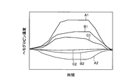
- the waveform A1 and the waveform A2 in FIG. 7 are oxygenated hemoglobin and deoxygenated when the oxygenated hemoglobin filter 11 and the deoxygenated hemoglobin filter 12 are moved so as to simulate the brain of a healthy person, respectively. It is a waveform of changes in each concentration of hemoglobin.
- the waveform B1 and the waveform B2 represent the oxygenated hemoglobin and the deoxygenated hemoglobin, respectively, when the oxygenated hemoglobin filter 11 and the deoxygenated hemoglobin filter 12 are moved so as to simulate the brain of a depressed patient. It is a waveform of the transition of each concentration.
- the waveform C1 and the waveform C2 are respectively oxygenated hemoglobin and deoxygenated hemoglobin when the oxygenated hemoglobin filter 11 and the deoxygenated hemoglobin filter 12 are moved so as to simulate the brain of a bipolar disorder person, respectively.
- 3 is a waveform of the transition of each concentration of.
- FIG. 7 is a schematic diagram for explaining that the waveforms are different from each other depending on the state of the brain, and may differ from the actual waveform.
- Each of the oxygenated hemoglobin filter 11 and the deoxygenated hemoglobin filter 12 is moved based on a program preset in the control unit 15 according to each brain state.
- a program preset in the control unit 15 for preparing programs corresponding to any brain state, any brain state can be obtained. It can be easily adapted.
- the oxygenated hemoglobin filter 11 and the deoxygenated hemoglobin filter 12 are configured to be movable, and the absorption rate of near-infrared light is increased for each portion along the movement direction.
- the phantom device 10 is configured differently. Accordingly, by moving the oxygenated hemoglobin filter 11 and the deoxygenated hemoglobin filter 12, it is possible to change the absorption amount of the near infrared light by each of the oxygenated hemoglobin filter 11 and the deoxygenated hemoglobin filter 12.
- the optical brain function measuring device 100 can be properly tested by accurately simulating the brain activity.
- the phantom device 10 can accurately simulate the actual brain activity, by comparing the test result obtained using the phantom device 10 with the actual brain data (waveform), It is possible to determine whether the function measuring device 100 is normal. As a result, the inspection result obtained by using the phantom device 10 in each device is different from that in the case of comparing the measurement data in each device between the devices having different characteristics (for example, the number of wavelengths of light to be irradiated). By comparing with the actual brain data (waveform), the performance of each device can be evaluated more accurately.
- the oxygenated hemoglobin filter 11 is configured such that the oxygenated hemoglobin absorption frequency distribution is substantially equal to the oxygenated hemoglobin absorption frequency distribution, and the deoxygenated hemoglobin filter 12 is provided. Is configured such that the absorption frequency distribution of deoxygenated hemoglobin is substantially equal to the absorption frequency distribution of deoxygenated hemoglobin.
- the control unit 15 controls the moving mechanism 14 in a state where light is applied to the overlapping portion of the oxygenated hemoglobin filter 11 and the deoxygenated hemoglobin filter 12. Then, the phantom device 10 is configured to move each of the oxygenated hemoglobin filter 11 and the deoxygenated hemoglobin filter 12 along the X direction. As a result, the moving mechanism 14 moves each of the oxygenated hemoglobin filter 11 and the deoxygenated hemoglobin filter 12, so that oxygen is compared to a case where the oxygenated hemoglobin filter 11 and the deoxygenated hemoglobin filter 12 are manually moved. The deoxygenated hemoglobin filter 11 and the deoxygenated hemoglobin filter 12 can be moved more accurately.
- the oxygenated hemoglobin filter 11 is configured such that the absorption rate of near-infrared light continuously changes along the X direction
- the deoxygenated hemoglobin filter 12 is provided. Is configured such that the absorption rate of near infrared light continuously changes along the X direction.
- the control unit 15 controls the moving mechanism 14 to configure the phantom device 10 so as to move the oxygenated hemoglobin filter 11 and the deoxygenated hemoglobin filter 12 along the X direction.
- the direction in which the oxygenated hemoglobin filter 11 and the deoxygenated hemoglobin filter 12 move and the direction in which the absorption rate of near infrared light changes in each of the oxygenated hemoglobin filter 11 and the deoxygenated hemoglobin filter 12 are aligned. ing.
- the absorption amount of near infrared light by the oxygenated hemoglobin filter 11 and the deoxygenated hemoglobin filter 12 can be easily changed.
- the brain activity can be simulated in detail (accurately).
- the control unit 15 controls the motors 14a and 14b individually to move the oxygenated hemoglobin filter 11 and the deoxygenated hemoglobin filter 12 independently.
- the phantom device 10 is configured to perform control.
- the motor 14a and the motor 14b independently move the oxygenated hemoglobin filter 11 and the deoxygenated hemoglobin filter 12, respectively, so that the absorption amount and the deoxygenation of the near infrared light by the oxygenated hemoglobin filter 11 are increased. It is possible to easily adjust the absorption amount by the hemoglobin filter 12 individually.
- control unit 15 controls the moving mechanism 14 to move the oxygenated hemoglobin filter 11 and the deoxygenated hemoglobin filter 12, and thereby the oxygenated hemoglobin filter 11 and
- the phantom device 10 is configured to perform control to generate a plurality of waveforms based on changes in the absorption amount of near infrared light by each of the deoxygenated hemoglobin filters 12.
- the brain activity of a plurality of symptoms is automatically discriminated. be able to.
- each of the oxygenated hemoglobin filter 11 and the deoxygenated hemoglobin filter 12 includes a color filter, and the shade of the color is different for each portion along the movement direction
- the phantom device 10 is configured so that the absorptance of near-infrared light differs for each part along the moving direction.
- the actual brain activity can be easily simulated by using the color filter without using the biological substance.
- the oxygenated hemoglobin filter 11 and the deoxygenated hemoglobin filter 12 are arranged side by side, and the intensity of light is increased.
- the phantom device 10 is configured to include the ND filter 13 that attenuates. Accordingly, the ND filter 13 can simulate the attenuation of light in the entire brain, and thus the brain activity can be more accurately simulated.
- the configuration of the phantom device 20 according to the second embodiment will be described with reference to FIGS. 1 and 8 to 11.
- the phantom device 20 of the second embodiment changes the absorption rate of near infrared light in each of the oxygenated hemoglobin filter 21 and the deoxygenated hemoglobin filter 22.
- the directions are different from each other.
- the same components as those in the first embodiment are designated by the same reference numerals as those in the first embodiment and shown in the drawings, and the description thereof will be omitted.
- the phantom device 20 is an example of the “phantom device for optical brain function measuring device” in the claims.
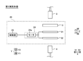
- the phantom device 20 used in the optical brain function measuring device 200 includes an oxygenated hemoglobin filter 21, a deoxygenated hemoglobin filter 22, a moving mechanism 24, and a controller 25. , Are provided.
- the moving mechanism 24 includes a motor 24a.
- the oxygenated hemoglobin filter 21 and the deoxygenated hemoglobin filter 22 are examples of the “first filter” and the “second filter” in the claims, respectively.
- the oxygenated hemoglobin filter 21 is configured such that the absorption rate of near-infrared light (color shade) continuously changes along the X direction. Specifically, in the oxygenated hemoglobin filter 21, a bright red color is more intensely colored and a near-infrared light absorption rate is higher in the X1 direction side portion than in the X2 direction side portion. Is becoming
- the deoxygenated hemoglobin filter 22 is configured such that the absorption rate (color shade) of near infrared light continuously changes along the Y direction orthogonal to the X direction. Specifically, the deoxygenated hemoglobin filter 22 has a darker red color and a higher absorption rate of near infrared light in the Y1 direction side portion than in the Y2 direction side portion. Is becoming
- the oxygenated hemoglobin filter 21 has a uniform absorption rate (color shade) of near infrared light in the directions (Y direction and Z direction) orthogonal to the X direction.
- the deoxygenated hemoglobin filter 22 has a uniform absorption rate (color shade) of near-infrared light in the directions (X direction and Z direction) orthogonal to the Y direction.
- each of the oxygenated hemoglobin filter 21 and the deoxygenated hemoglobin filter 22 has, for example, a substantially square shape when viewed from the direction (Z direction) in which the optical axis of the near infrared light extends. ing.
- the shapes of the oxygenated hemoglobin filter 21 and the deoxygenated hemoglobin filter 22 are not limited to this.
- the control unit 25 controls the moving mechanism 24 to move the oxygenated hemoglobin filter 21 and the deoxygenated hemoglobin filter 22 in the direction in which the optical axis of the near infrared light extends (Z direction). It is configured to move along a plane (XY plane) orthogonal to. Specifically, each of the oxygenated hemoglobin filter 21 and the deoxygenated hemoglobin filter 22 is movable in the X direction, the Y direction, and the diagonal direction on the XY plane.
- the control unit 25 is also configured to control the moving mechanism 24 to integrally move the oxygenated hemoglobin filter 21 and the deoxygenated hemoglobin filter 22.
- the motor 24a of the moving mechanism 24 is a motor common to both the oxygenated hemoglobin filter 21 and the deoxygenated hemoglobin filter 22, and moves the oxygenated hemoglobin filter 21 and the deoxygenated hemoglobin filter 22 integrally. Is configured to.
- integrally moving means that the moving timing, the moving direction, and the moving amount are common to each other.
- the oxygenated hemoglobin filter 21 and the deoxygenated hemoglobin filter 22 have substantially the same size when viewed from the Z direction. Specifically, the length L11 (see FIG. 9) of the oxygenated hemoglobin filter 21 in the X direction is substantially equal to the length L12 (see FIG. 9) of the deoxygenated hemoglobin filter 22 in the X direction. Further, the length L13 of the oxygenated hemoglobin filter 21 in the Y direction is substantially equal to the length L14 of the deoxygenated hemoglobin filter 22 in the Y direction.
- the oxygenated hemoglobin filter 11 and the deoxygenated hemoglobin filter 12 are provided so that their positions in the X and Y directions are aligned with each other (see FIG. 4). That is, the oxygenated hemoglobin filter 21 and the deoxygenated hemoglobin filter 22 move integrally in a state where all of them overlap each other when viewed from the Z direction.
- the control unit 25 causes the motor 24a so that the near-infrared light from the light transmitting fiber 3 passes through the points a, b, c, d, and e in the order of FIG. 10 (broken line in FIG. 10).
- the oxygenated hemoglobin filter 21 and the deoxygenated hemoglobin filter 22 are integrally moved.
- the points a and e are the same point.
- the waveforms of the transition of the values calculated as the concentrations of oxygenated hemoglobin and deoxygenated hemoglobin are as waveform D1 and waveform D2 in FIG. 11, respectively. Further, by controlling the movement of the oxygenated hemoglobin filter 21 and the deoxygenated hemoglobin filter 22, it is possible to generate an arbitrary waveform.
- the five points a to e are described as an example for description, but not only the five points a to e, but the oxygenated hemoglobin filter 21 and the deoxygenated hemoglobin filter 22 are also included.
- the waveform may be generated from a plurality (five or more points) of measurement data continuously acquired during the movement of the.
- the oxygenated hemoglobin filter 21 is configured such that the absorption rate of near-infrared light continuously changes along the X direction
- the deoxygenated hemoglobin filter 22 includes: The absorptance of near infrared light continuously changes along the Y direction.
- the control unit 25 configures the phantom device 10 so as to control the moving mechanism 24 (motor 24a) to move the oxygenated hemoglobin filter 21 and the deoxygenated hemoglobin filter 22 along the XY plane.
- the X direction in which the absorption rate of near infrared light changes in the oxygenated hemoglobin filter 21 and the Y direction in which the absorption rate of near infrared light changes in the deoxygenated hemoglobin filter 22 intersect orthogonal.
- the combination with the absorption rate of the near infrared light in the hemoglobin filter 22 can be changed two-dimensionally (for each coordinate in the XY plane).
- the absorption amount of the oxygenated hemoglobin filter 21 to the near infrared light and the deoxygenated hemoglobin filter can be easily adjusted.
- control unit 25 controls the moving mechanism 24 (motor 24a) to move the oxygenated hemoglobin filter 21 and the deoxygenated hemoglobin filter 22 integrally. Then, the phantom device 10 is configured. Thereby, in the case of moving the oxygenated hemoglobin filter 21 and the deoxygenated hemoglobin filter 22 two-dimensionally, compared to the case of moving the oxygenated hemoglobin filter 21 and the deoxygenated hemoglobin filter 22 individually The control load on the unit 25 can be reduced.
- the oxygenated hemoglobin filter (11, 21) (first filter) and the deoxygenated hemoglobin filter (12, 22) (second filter) are arranged in the light transmitting fiber 3 (light source).
- Part) and the light receiving fiber 4 (detection part) are shown as an example, but the present invention is not limited to this.
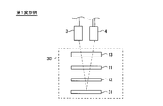
- the phantom device 30 includes a total reflection mirror 31.
- the total reflection mirror 31 reflects the near infrared light from the light transmitting fiber 3 toward the light receiving fiber 4.
- Each of the oxygenated hemoglobin filter 11 and the deoxygenated hemoglobin filter 12 is arranged between the light transmitting fiber 3 and the light receiving fiber 4 and the total reflection mirror 31. Note that, in FIG. 12, members unnecessary for description are omitted for simplification.
- the total reflection mirror 31 and the phantom device 30 are examples of the “reflection unit” and the “phantom device for optical brain function measuring device” in the claims, respectively.
- the near infrared light from the light transmitting fiber 3 passes through the ND filter 13, the oxygenated hemoglobin filter 11, and the deoxygenated hemoglobin filter 12, and is reflected by the total reflection mirror 31. Then, the near-infrared light reflected by the total reflection mirror 31 passes through the deoxygenated hemoglobin filter 12, the oxygenated hemoglobin filter 11, and the ND filter 13 and is received by the light receiving fiber 4.
- the configuration may be such that the total reflection mirror 31 is provided.
- the optical brain function measuring device generally, the near-infrared light emitted from the device attached to the brain and reflected in the brain is measured by the above device to perform the measurement. Therefore, each of the oxygenated hemoglobin filter 11 and the deoxygenated hemoglobin filter 12 is arranged between the light transmitting fiber 3 and the light receiving fiber 4 and the total reflection mirror 31, so that the optical brain function measuring device is used. It is possible to perform an examination under conditions (structure) close to those of an actual brain examination.
- each of the oxygenated hemoglobin filter (11, 21) (first filter) and the deoxygenated hemoglobin filter (12, 22) (second filter) has a flat plate shape.
- the present invention is not limited to this.
- each of the oxygenated hemoglobin filter 41 and the deoxygenated hemoglobin filter 42 has a different thickness in the Z direction for each portion along the movement direction (X direction). That is, each of the oxygenated hemoglobin filter 41 and the deoxygenated hemoglobin filter 42 has a wedge shape. Specifically, in each of the oxygenated hemoglobin filter 41 and the deoxygenated hemoglobin filter 42, the portion in the X1 direction side has a larger thickness in the Z direction than the portion in the X2 direction side.
- the oxygenated hemoglobin filter 41 and the deoxygenated hemoglobin filter 42 respectively have an inclined surface 41a and an inclined surface 42a that are inclined with respect to the direction (Z direction) in which the optical axis of the near infrared light extends.
- the oxygenated hemoglobin filter 41 and the deoxygenated hemoglobin filter 42 are examples of the “first filter” and the “second filter” in the claims, respectively. Further, also in the configuration of the second embodiment, each filter may have an inclined surface.
- each of the oxygenated hemoglobin filter 41 and the deoxygenated hemoglobin filter 42 has a different absorption rate of near infrared light for each portion along the moving direction (X direction). That is, in each of the oxygenated hemoglobin filter 41 and the deoxygenated hemoglobin filter 42, the portion in the X1 direction side where the thickness in the Z direction is large is closer to the near infrared than the portion in the X2 direction side where the thickness in the Z direction is smaller. High light absorption.
- each of the oxygenated hemoglobin filter 41 and the deoxygenated hemoglobin filter 42 has a uniform color shade for each part.
- at least one of the oxygenated hemoglobin filter 41 and the deoxygenated hemoglobin filter 42 may be configured so that the thickness thereof changes in the Y direction.
- the oxygenated hemoglobin filter (21) (first filter) and the deoxygenated hemoglobin filter (22) (second filter) are moved
- the present invention is not limited to this. I can't. With the oxygenated hemoglobin filter (21) (first filter) and the deoxygenated hemoglobin filter (22) (second filter) fixed, the light transmitting fiber 3 (light source unit) and the light receiving fiber 4 (detecting unit) are moved. You may let me.
- the oxygenated hemoglobin filter (11, 21) (first filter) and the deoxygenated hemoglobin filter (12, 22) (second filter) are respectively oxygenated hemoglobin and An example in which the absorption frequency portion of deoxygenated hemoglobin is approximately equal has been shown, but the present invention is not limited to this.
- the oxygenated hemoglobin filter (11, 21) (first filter) and the deoxygenated hemoglobin filter (12, 22) (second filter) absorb the biological substances other than the oxygenated hemoglobin and the deoxygenated hemoglobin, respectively, approximately equal to each other. It may have a frequency distribution.
- the oxygenated hemoglobin filters (11, 21) (first filter) and the deoxygenated hemoglobin filters (12, 22) (second filter) are driven by the motors (14a, 14b, 24a).
- the present invention is not limited to this.
- the oxygenated hemoglobin filters (11, 21) (first filter) and the deoxygenated hemoglobin filters (12, 22) (second filter) may be manually moved.
- the oxygenated hemoglobin filter 11 (first filter) and the deoxygenated hemoglobin filter 12 (second filter) each absorb near infrared light (light) on the X1 direction side.
- the rate is high
- the present invention is not limited to this.
- at least one of the oxygenated hemoglobin filter 11 (first filter) and the deoxygenated hemoglobin filter 12 (second filter) has a higher absorption rate of near infrared light (light) on the X2 direction side. Good.
- the direction in which the absorptance changes is orthogonal is shown, the present invention is not limited to this.
- a direction in which the absorption rate of near infrared light in the oxygenated hemoglobin filter 21 (first filter) changes and a direction in which the absorption rate of near infrared light in the deoxygenated hemoglobin filter 22 (second filter) changes. May intersect without being orthogonal to each other.
- the oxygenated hemoglobin filter 21 (first filter) and the deoxygenated hemoglobin filter 22 (second filter) move integrally, but the present invention is not limited to this. Not limited.
- each of the oxygenated hemoglobin filter 21 (first filter) and the deoxygenated hemoglobin filter 22 (second filter) may be independently moved.
- each of the oxygenated hemoglobin filter (11, 21) (first filter) and the deoxygenated hemoglobin filter (12, 22) (second filter) is a color filter.
- each of the oxygenated hemoglobin filter (11, 21) (first filter) and the deoxygenated hemoglobin filter (12, 22) (second filter) may be other than the color filter.
- the moving mechanism 24 includes one motor 24a
- the present invention is not limited to this.
- the moving mechanism 24 may include two motors so as to correspond to the oxygenated hemoglobin filter 21 (first filter) and the deoxygenated hemoglobin filter 22 (second filter), respectively.
- Optical fiber (light source) 4 Light receiving fiber (detector) 10, 20, 30 Phantom device (Phantom device for optical brain function measurement device) 11, 21, 41 Oxygenated hemoglobin filter (first filter) 12, 22, 42 Deoxygenated hemoglobin filter (second filter) 13 ND filter (third filter) 14, 24 moving mechanism 14a motor (first moving mechanism) 14b motor (second moving mechanism) 15, 25 Control unit 31 Total reflection mirror (reflection unit) 100, 200 Optical brain function measuring device A1, A2, B1, B2, C1, C2, D1, D2 Waveform X direction (first direction) Y direction (second direction)
Landscapes
- Health & Medical Sciences (AREA)
- Life Sciences & Earth Sciences (AREA)
- General Health & Medical Sciences (AREA)
- Pathology (AREA)
- Physics & Mathematics (AREA)
- Chemical & Material Sciences (AREA)
- Analytical Chemistry (AREA)
- Biochemistry (AREA)
- General Physics & Mathematics (AREA)
- Immunology (AREA)
- Engineering & Computer Science (AREA)
- Biomedical Technology (AREA)
- Heart & Thoracic Surgery (AREA)
- Medical Informatics (AREA)
- Molecular Biology (AREA)
- Surgery (AREA)
- Animal Behavior & Ethology (AREA)
- Public Health (AREA)
- Veterinary Medicine (AREA)
- Investigating Or Analysing Materials By Optical Means (AREA)
- Measurement Of The Respiration, Hearing Ability, Form, And Blood Characteristics Of Living Organisms (AREA)
Abstract
この光脳機能計測装置用ファントム装置(100)は、互いに吸収周波数分布が異なるとともに少なくとも一部が互いにオーバラップする第1フィルタ(11)と第2フィルタ(12)とを備える。また、第1フィルタ(11)および第2フィルタ(12)は、光源部(3)および検出部(4)に対する相対的な移動方向に沿った部分毎に光の吸収率が異なる。
Description
本発明は、光脳機能計測装置用ファントム装置に関し、特に、所定の吸収周波数分布を有するフィルタを備える光脳機能計測装置用ファントム装置に関する。
従来、所定の吸収周波数分布を有するフィルタを備える光脳機能計測装置用ファントム装置が知られている。このような光脳機能計測装置用ファントム装置は、たとえば、特開2009-195387号公報に開示されている。
上記特開2009-195387号公報の生体光計測装置の検査用ファントム装置には、主散乱体、補助散乱体、光吸収体(フィルタ)、および、駆動装置が設けられている。主散乱体および補助散乱体の各々は、光を反射する粉体が均等に混入された樹脂を平板上に成型した矩形の樹脂板により構成されている。また、主散乱体および補助散乱体の各々は、光透過性を有し、かつ、内部に入射された光を散乱させる。また、補助散乱体は、所定の間隔をおいて、主散乱体の一方側の面と対向している。また、光吸収体は、駆動装置により制御され、主散乱体と補助散乱体との間において移動するように構成されている。
また、上記特開2009-195387号公報の生体光計測装置の検査用ファントム装置では、主散乱体の他方側の面には、光を照射する複数の照射プローブと、光を検出する複数の検出プローブが設けられている。照射プローブから照射された光は、主散乱体の一方側の面から出射され、一部が光吸収体に吸収され、残りの一部が補助散乱体に入射する。補助散乱体に入射された光は、補助散乱体内で拡散され、一部が再び主散乱体に入射する。そして、再び主散乱体に入射された光は検出プローブにより検出される。検出プローブにより検出された計測値に基づいた計測データと、予め設定されていた正常時のデータとを比較することにより、生体光計測装置が正常であるか否かを検知することが可能である。
しかしながら、上記特開2009-195387号公報に記載されている生体光計測装置の検査用ファントム装置では、上記特開2009-195387号公報には明記されていないが、主散乱体から出射された光は、光吸収体(フィルタ)によって吸収されることにより、光の周波数によらず一律に強度が減衰すると考えられる。ここで、人体(脳)には、光に対する吸収周波数分布(吸収スペクトル)が互いに異なる複数の生体物質が含まれている。また、複数の生体物質のうちの一の生体物質(以下、第1生体物質)および他の生体物質(以下、第2生体物質)の各々の濃度(量)は、脳活動に応じて、互いに異なる変化率で変化する場合がある。したがって、上記の光吸収体(フィルタ)を用いて一律に光の強度を減衰させる上記特開2009-195387号公報の検査用ファントム装置では、第1生体物質の濃度(量)および第2生体物質の濃度(量)が互いに異なる変化率で変化する実際の脳活動の動作を正確に模擬することが困難であるという不都合がある。このため、上記特開2009-195387号公報の検査用ファントム装置では、実際の脳の検査時とは異なる条件において生体光計測装置の検査が行われるため、生体光計測装置の検査が不適切になる場合があるという問題点がある。
この発明は、上記のような課題を解決するためになされたものであり、この発明の1つの目的は、脳活動を正確に模擬することにより、光脳機能計測装置を適切に検査することが可能な光脳機能計測装置用ファントム装置を提供することである。
上記目的を達成するために、この発明の一の局面における光脳機能計測装置用ファントム装置は、光を照射する光源部と、光源部からの光を検出する検出部とを備える光脳機能計測装置に用いる光脳機能計測装置用ファントム装置であって、光源部からの光が照射され、光に対して第1吸収周波数分布を有する第1フィルタと、光源部からの光が照射され、第1フィルタの第1吸収周波数分布とは吸収周波数分布が異なる第2吸収周波数分布を有するとともに、光源部からの光の光軸が延びる方向から見て、少なくとも一部が第1フィルタとオーバーラップするように設けられる第2フィルタと、を備え、第1フィルタおよび第2フィルタは、光源部および検出部に対して相対的に移動可能に構成されているとともに、光源部および検出部に対する相対的な移動方向に沿った部分毎に光の吸収率が異なるように構成されている。
この発明の一の局面における光脳機能計測装置用ファントム装置では、上記のように、第1フィルタおよび第2フィルタは、光源部および検出部に対する相対的な移動方向に沿った部分毎に光の吸収率が異なる。これにより、光源部および検出部に対して、第1フィルタおよび第2フィルタを相対的に移動させることにより、第1フィルタおよび第2フィルタの各々による光の吸収量を変化させることができる。また、第1フィルタおよび第2フィルタの移動を制御することによって、第1フィルタおよび第2フィルタの各々による光の吸収量を異なる変化率で変化させることを容易に行うことができる。これらの結果、第1吸収周波数分布を有する生体物質の濃度(量)、および、第2吸収周波数分布を有する生体物質の濃度(量)が互いに異なる変化率で変化する実際の脳活動を正確に模擬することができる。これにより、脳活動を正確に模擬することにより、光脳機能計測装置を適切に検査することができる。
また、光脳機能計測装置用ファントム装置により実際の脳活動を正確に模擬することができるので、ファントム装置を用いて得られた検査結果と、実際の脳のデータ(波形)とを比較することにより、光脳機能計測装置が正常であるか否かを判断することができる。これにより、特性(たとえば照射する光の波長数等)が互いに異なる装置間において、各装置における計測データ同士を比較する場合に比べて、各装置においてファントム装置を用いて得られた検査結果と実際の脳のデータ(波形)との比較を行うことにより、各装置の性能評価をより精度良く行うことができる。
上記一の局面における光脳機能計測装置用ファントム装置において、好ましくは、第1フィルタおよび第2フィルタの各々には、光源部からの近赤外光が照射され、第1フィルタは、第1吸収周波数分布が、酸素化ヘモグロビンの吸収周波数分布と略等しくなるように構成され、第2フィルタは、第2吸収周波数分布が、脱酸素化ヘモグロビンフィルタの吸収周波数分布と略等しくなるように構成されている。このように構成すれば、酸素化ヘモグロビンの濃度(量)、および、脱酸素化ヘモグロビンの濃度(量)が互いに異なる変化率で変化する症状(たとえばうつ病)の脳活動を容易に模擬することができる。
上記一の局面における光脳機能計測装置用ファントム装置において、好ましくは、光源部および検出部に対して、第1フィルタおよび第2フィルタを相対的に移動させる移動機構と、移動機構を制御する制御部と、をさらに備え、制御部は、第1フィルタと第2フィルタとがオーバーラップした部分に光が照射された状態で、移動機構を制御して、光源部および検出部に対して、第1フィルタおよび第2フィルタの各々を、光軸が延びる方向に直交する方向に沿って相対的に移動させるように構成されている。このように構成すれば、移動機構により第1フィルタおよび第2フィルタの各々を移動させることによって、手動で第1フィルタおよび第2フィルタを移動させる場合に比べて、第1フィルタおよび第2フィルタをより正確に移動させることができる。
この場合、好ましくは、第1フィルタは、光軸が延びる方向に直交する面における第1の方向に沿って、光の吸収率が連続的に変化するように構成され、第2フィルタは、第1の方向に沿って、光の吸収率が連続的に変化するように構成されており、制御部は、移動機構を制御して、光源部および検出部に対して、第1フィルタおよび第2フィルタを、第1の方向に沿って相対的に移動させるように構成されている。このように構成すれば、第1フィルタおよび第2フィルタが光源部および検出部に対して相対的に移動する方向と、第1フィルタおよび第2フィルタの各々において光の吸収率が変化する方向とが揃っている。その結果、第1フィルタおよび第2フィルタを、光源部および検出部に対して相対的に移動させることによって、第1フィルタおよび第2フィルタによる光の吸収量を容易に変化させることができる。
また、第1フィルタおよび第2フィルタの各々において光の吸収率が連続的に変化するので、光の吸収率がステップ状(非連続的)に変化する場合に比べて、より細かく(正確に)脳活動を模擬することができる。
上記光源部および検出部に対して第1フィルタおよび第2フィルタを第1の方向に沿って相対的に移動させる光脳機能計測装置用ファントム装置において、好ましくは、移動機構は、光源部および検出部に対して、第1フィルタを相対的に移動させる第1移動機構と、光源部および検出部に対して、第2フィルタを相対的に移動させる第2移動機構とを含み、制御部は、第1移動機構および第2移動機構を個別に制御して、第1フィルタおよび第2フィルタの各々を独立して移動させる制御を行うように構成されている。このように構成すれば、第1移動機構および第2移動機構により、第1フィルタおよび第2フィルタの各々を独立して移動させることによって、光に対する第1フィルタによる吸収量と第2フィルタによる吸収量とを個別に調整するのを容易化することができる。
上記移動機構を備える光脳機能計測装置用ファントム装置において、好ましくは、第1フィルタは、光軸が延びる方向に直交する面における第1の方向に沿って、光の吸収率が連続的に変化するように構成され、第2フィルタは、光軸が延びる方向に直交する面において第1の方向と交差する第2の方向に沿って、光の吸収率が連続的に変化するように構成されており、制御部は、移動機構を制御して、光源部および検出部に対して、第1フィルタおよび第2フィルタを、光軸が延びる方向に直交する面に沿って相対的に移動させるように構成されている。このように構成すれば、第1フィルタにおいて光の吸収率が変化する第1の方向と、第2フィルタにおいて光の吸収率が変化する第2の方向とが交差することによって、光軸が延びる方向から見て第1フィルタおよび第2フィルタがオーバーラップする部分の、第1フィルタにおける光の吸収率と第2フィルタにおける光の吸収率との組み合わせを2次元的に(第1の方向と第2の方向との面内の座標毎に)変化させることができる。その結果、光源部および検出部に対して、第1フィルタおよび第2フィルタを、光軸が延びる方向に直交する面に沿って相対的に、かつ、2次元的に移動させることによって、光に対する第1フィルタによる吸収量と第2フィルタによる吸収量とを容易に調整することができる。
この場合、好ましくは、制御部は、移動機構を制御して、第1フィルタと第2フィルタとを一体的に移動させるように構成されている。このように構成すれば、第1フィルタと第2フィルタとを2次元的に移動させる場合において、第1フィルタと第2フィルタとを個別に移動させる場合に比べて、制御部の制御負荷を軽減することができる。
上記移動機構を備える光脳機能計測装置用ファントム装置において、好ましくは、制御部は、移動機構を制御して、第1フィルタおよび第2フィルタを、光源部および検出部に対して相対的に移動させることにより、第1フィルタおよび第2フィルタの各々による光の吸収量の変化に基づく複数の波形を生成する制御を行うように構成されている。このように構成すれば、複数の波形を生成することにより、複数の症状の脳活動を模擬することができる。
また、複数の脳の状態を模擬した複数の波形が生成されることによって、実際の脳の計測データと上記波形とをソフトウェアにより比較した場合に、複数の症状の脳活動を自動的に判別することができる。
上記一の局面における光脳機能計測装置用ファントム装置において、好ましくは、光源部からの光を検出部に向かって反射する反射部をさらに備え、第1フィルタおよび第2フィルタの各々は、光源部および検出部と反射部との間に配置されている。ここで、光脳機能計測装置では、一般的に、脳に装着された装置から照射され、脳内において反射された光を、上記装置により検出することにより計測が行われる。したがって、第1フィルタおよび第2フィルタの各々が、光源部および検出部と反射部との間に配置されていることによって、光脳機能計測装置を用いた実際の脳の検査に近い条件(構成)での検査を行うことができる。
上記一の局面における光脳機能計測装置用ファントム装置において、好ましくは、第1フィルタおよび第2フィルタの各々は、カラーフィルタを含み、光源部および検出部に対する相対的な移動方向に沿った部分毎に色の濃淡が異なることにより、光源部および検出部に対する相対的な移動方向に沿った部分毎に光の吸収率が異なるように構成されている。このように構成すれば、生体物質を用いなくても、カラーフィルタを用いることによって、実際の脳活動を容易に模擬することができる。
上記一の局面における光脳機能計測装置用ファントム装置において、好ましくは、第1フィルタおよび第2フィルタの各々は、光源部からの光の光軸が延びる方向における厚みが、光源部および検出部に対する相対的な移動方向に沿った部分毎に異なることによって、光源部および検出部に対する相対的な移動方向に沿った部分毎に光の吸収率が異なるように構成されている。このように構成すれば、色の濃淡を調整することなく、厚みを調整するだけで、第1フィルタおよび第2フィルタの各々の光の吸収率を容易に調整することができる。
上記一の局面における光脳機能計測装置用ファントム装置において、好ましくは、光源部からの光の光軸が延びる方向において、第1フィルタおよび第2フィルタと並んで配置され、光の強度を減衰させる第3フィルタをさらに備える。このように構成すれば、第3フィルタにより、脳内全体の光の減衰を模擬することができるので、脳活動をより一層正確に模擬することができる。
本発明によれば、上記のように、脳活動を正確に模擬することにより、光脳機能計測装置を適切に検査することができる。
以下、本発明を具体化した実施形態を図面に基づいて説明する。
[第1実施形態]
まず、図1~図7を参照して、第1実施形態によるファントム装置10の全体構成について説明する。第1実施形態では、ファントム装置10は、近赤外分光法(NIRS)による光計測(脳機能計測)を行う光脳機能計測装置100に用いられるファントム装置である。なお、ファントム装置10は、請求の範囲の「光脳機能計測装置用ファントム装置」の一例である。
まず、図1~図7を参照して、第1実施形態によるファントム装置10の全体構成について説明する。第1実施形態では、ファントム装置10は、近赤外分光法(NIRS)による光計測(脳機能計測)を行う光脳機能計測装置100に用いられるファントム装置である。なお、ファントム装置10は、請求の範囲の「光脳機能計測装置用ファントム装置」の一例である。
(光脳機能計測装置の構成)
図1に示すように、光脳機能計測装置100は、光計測ユニット1と、制御ユニット2とから構成されている。光脳機能計測装置100は、送光ファイバ3と、受光ファイバ4とを備えている。また、光脳機能計測装置100は、光ファイバ5を介して接続された送光ファイバ3および受光ファイバ4を用いて、被験者(被検体)の脳活動を計測する機能を有する。なお、送光ファイバ3および受光ファイバ4は、それぞれ、請求の範囲の「光源部」および「検出部」の一例である。
図1に示すように、光脳機能計測装置100は、光計測ユニット1と、制御ユニット2とから構成されている。光脳機能計測装置100は、送光ファイバ3と、受光ファイバ4とを備えている。また、光脳機能計測装置100は、光ファイバ5を介して接続された送光ファイバ3および受光ファイバ4を用いて、被験者(被検体)の脳活動を計測する機能を有する。なお、送光ファイバ3および受光ファイバ4は、それぞれ、請求の範囲の「光源部」および「検出部」の一例である。
光脳機能計測装置100の送光ファイバ3および受光ファイバ4は、それぞれ、被験者の頭部に装着されたプローブ固定用のホルダ6に取り付けられることにより、被験者の頭部表面上の所定位置に配置される。そして、光脳機能計測装置100は、送光ファイバ3から照射される近赤外光の波長領域の計測光を照射し、被験者の頭内で反射した計測光を受光ファイバ4に入射させて検出することにより、計測光の強度(受光量)を取得する。取得した計測光の強度に基づいて、脳活動に伴うヘモグロビン量(酸素化ヘモグロビン、脱酸素化へモグロビンおよび総ヘモグロビン)の変化を取得することが可能である。これにより、光脳機能計測装置100は、脳活動に伴うヘモグロビン量の変化、すなわち血流量の変化や酸素代謝の活性化状態を非侵襲で取得することが可能である。光計測では、送光ファイバ3および受光ファイバ4のペアによって構成される計測点毎に、脳活動が計測される。計測データは、脳機能計測におけるレスト期間に対するタスク期間の相対的なヘモグロビン変化量として取得される。なお、近赤外光は、請求の範囲の「光」の一例である。
また、光脳機能計測装置100では、受光ファイバ4により受光された近赤外光に基づいて取得された計測データが、通信により光計測ユニット1から制御ユニット2に送信される。そして、制御ユニット2において、光計測ユニット1から送信された計測データが解析される。なお、制御ユニット2は、液晶ディスプレイなどからなる表示部2aを備えている。
(ファントム装置の構成)
図2に示すように、ファントム装置10により光脳機能計測装置100の検査を行う際には、送光ファイバ3および受光ファイバ4は、互いに対向するように直線状に並べて配置される。送光ファイバ3および受光ファイバ4が並ぶ方向を、第1実施形態ではZ方向とする。送光ファイバ3は、受光ファイバ4に対してZ1方向側に配置されている。なお、図2では、光計測ユニット1および制御ユニット2は、簡略化のため、図示を省略している。
図2に示すように、ファントム装置10により光脳機能計測装置100の検査を行う際には、送光ファイバ3および受光ファイバ4は、互いに対向するように直線状に並べて配置される。送光ファイバ3および受光ファイバ4が並ぶ方向を、第1実施形態ではZ方向とする。送光ファイバ3は、受光ファイバ4に対してZ1方向側に配置されている。なお、図2では、光計測ユニット1および制御ユニット2は、簡略化のため、図示を省略している。
ファントム装置10は、酸素化ヘモグロビンフィルタ11と、脱酸素化ヘモグロビンフィルタ12と、ND(Neutral Density)フィルタ13とを備えている。酸素化ヘモグロビンフィルタ11、脱酸素化ヘモグロビンフィルタ12、および、NDフィルタ13の各々は、送光ファイバ3と受光ファイバ4との間において、Z方向に並んで配置されている。具体的には、送光ファイバ3側(Z1方向側)から順に、NDフィルタ13、酸素化ヘモグロビンフィルタ11、脱酸素化ヘモグロビンフィルタ12の順に配置されている。酸素化ヘモグロビンフィルタ11、脱酸素化ヘモグロビンフィルタ12、および、NDフィルタ13の並び順はこれに限られない。なお、酸素化ヘモグロビンフィルタ11および脱酸素化ヘモグロビンフィルタ12は、それぞれ、請求の範囲の「第1フィルタ」および「第2フィルタ」の一例である。また、NDフィルタ13は、請求の範囲の「第3フィルタ」の一例である。
これにより、酸素化ヘモグロビンフィルタ11、脱酸素化ヘモグロビンフィルタ12、および、NDフィルタ13の各々には、送光ファイバ3からの近赤外光が照射される。具体的には、酸素化ヘモグロビンフィルタ11には、NDフィルタ13を透過した近赤外光が照射される。また、脱酸素化ヘモグロビンフィルタ12には、NDフィルタ13および酸素化ヘモグロビンフィルタ11を透過した近赤外光が照射される。
また、酸素化ヘモグロビンフィルタ11、脱酸素化ヘモグロビンフィルタ12、および、NDフィルタ13の各々は、Z方向に直交する平面(XY平面)に延びる平板形状を有している。また、酸素化ヘモグロビンフィルタ11および脱酸素化ヘモグロビンフィルタ12の各々は、矩形形状(図4および図5参照)を有している。なお、酸素化ヘモグロビンフィルタ11および脱酸素化ヘモグロビンフィルタ12の各々の形状は、これに限られない。
また、酸素化ヘモグロビンフィルタ11および脱酸素化ヘモグロビンフィルタ12は、互いに略等しい大きさを有している。具体的には、酸素化ヘモグロビンフィルタ11のX方向の長さL1(図5参照)は、脱酸素化ヘモグロビンフィルタ12のX方向の長さL2(図5参照)と略等しい。また、酸素化ヘモグロビンフィルタ11のY方向の長さL3は、脱酸素化ヘモグロビンフィルタ12のY方向の長さL4と略等しい。なお、酸素化ヘモグロビンフィルタ11および脱酸素化ヘモグロビンフィルタ12の各々は、Y方向における位置が互いに揃う(図4参照)ように設けられている。なお、X方向およびY方向は、それぞれ、請求の範囲の「第1の方向」および「第2の方向」の一例である。
ここで、第1実施形態では、図3に示すように、酸素化ヘモグロビンフィルタ11は、近赤外光に対して所定の吸収周波数分布(吸収スペクトル)(実線参照)を有する。酸素化ヘモグロビンフィルタ11の近赤外光に対する吸収周波数分布を、以下では酸素化ヘモグロビン吸収周波数分布とする。この酸素化ヘモグロビン吸収周波数分布は、酸素化ヘモグロビンの吸収周波数分布と略等しい。なお、酸素化ヘモグロビン吸収周波数分布は、請求の範囲の「第1吸収周波数分布」の一例である。
また、脱酸素化ヘモグロビンフィルタ12は、近赤外光に対して、酸素化ヘモグロビン吸収周波数分布(図3の破線参照)とは異なる吸収周波数分布を有する。脱酸素化ヘモグロビンフィルタ12の吸収周波数分布を、以下では脱酸素化ヘモグロビン吸収周波数分布とする。この脱酸素化ヘモグロビン吸収周波数分布は、脱酸素化ヘモグロビンの吸収周波数分布と略等しい。なお、脱酸素化ヘモグロビン吸収周波数分布は、請求の範囲の「第2吸収周波数分布」の一例である。
図3に示すように、酸素化ヘモグロビンフィルタ11と脱酸素化ヘモグロビンフィルタ12とでは、吸光係数が比較的大きい周波数帯が互いに異なっている。たとえば、近赤外光の周波数帯(たとえば750nm以上950nm以下)において、酸素化ヘモグロビン吸収周波数分布では、周波数が大きくなるほど吸光係数は大きくなる傾向にあるが、脱酸素化ヘモグロビン吸収周波数分布では、周波数が大きくなるほど吸光係数は小さくなる傾向にある。
また、酸素化ヘモグロビンフィルタ11および脱酸素化ヘモグロビンフィルタ12の各々は、カラーフィルタを含む。具体的には、酸素化ヘモグロビンフィルタ11は、酸素化ヘモグロビンを多く含む血液の色である鮮やかな赤色のカラーフィルタである。また、脱酸素化ヘモグロビンフィルタ12は、脱酸素化ヘモグロビンを多く含む血液の色である暗い赤色のカラーフィルタである。
また、第1実施形態では、NDフィルタ13は、近赤外光の強度を減衰させる。すなわち、近赤外光の周波数によらず、NDフィルタ13を通過した近赤外光は、一律に強度が減衰される。
また、図2に示すように、酸素化ヘモグロビンフィルタ11および脱酸素化ヘモグロビンフィルタ12の各々は、送光ファイバ3および受光ファイバ4に対して相対的に移動可能に構成されている。具体的には、ファントム装置10は、酸素化ヘモグロビンフィルタ11および脱酸素化ヘモグロビンフィルタ12を移動させる移動機構14を備える。なお、送光ファイバ3および受光ファイバ4の各々は、移動せずに固定されている。
また、ファントム装置10は、移動機構14を制御する制御部15を備える。具体的には、制御部15は、後述する、モータ14aおよびモータ14bの各々を制御するように構成されている。
移動機構14は、酸素化ヘモグロビンフィルタ11を移動させるモータ14aを含む。また、移動機構14は、脱酸素化ヘモグロビンフィルタ12を移動させるモータ14bを含む。モータ14aおよびモータ14bは、それぞれ、酸素化ヘモグロビンフィルタ11および脱酸素化ヘモグロビンフィルタ12をX方向(X1方向およびX2方向)に移動させるように構成されている。なお、酸素化ヘモグロビンフィルタ11および脱酸素化ヘモグロビンフィルタ12の各々の移動速度は、たとえば1cm/秒程度である。また、モータ14aおよびモータ14bは、それぞれ、請求の範囲の「第1移動機構」および「第2移動機構」の一例である。
ここで、第1実施形態では、制御部15は、モータ14aおよびモータ14bを個別に制御して、酸素化ヘモグロビンフィルタ11および脱酸素化ヘモグロビンフィルタ12の各々を独立して移動させる制御を行う。具体的には、制御部15は、酸素化ヘモグロビンフィルタ11および脱酸素化ヘモグロビンフィルタ12の各々の移動量、移動する方向、および、移動の有無を個別に制御する。
なお、脱酸素化ヘモグロビンフィルタ12は、近赤外光の光軸が延びる方向(Z方向)から見て、少なくとも一部が酸素化ヘモグロビンフィルタ11とオーバーラップ(図4参照)するように設けられている。
また、第1実施形態では、制御部15は、酸素化ヘモグロビンフィルタ11と脱酸素化ヘモグロビンフィルタ12とがオーバーラップした部分(図4の斜線部分)に近赤外光が照射された状態で、移動機構14(モータ14a、モータ14b)を制御して、酸素化ヘモグロビンフィルタ11および脱酸素化ヘモグロビンフィルタ12の各々を、X方向に移動させるように構成されている。すなわち、酸素化ヘモグロビンフィルタ11および脱酸素化ヘモグロビンフィルタ12の各々が移動した場合でも、送光ファイバ3からの近赤外光は、必ず、酸素化ヘモグロビンフィルタ11および脱酸素化ヘモグロビンフィルタ12の両方を通過する。
ここで、第1実施形態では、図5に示すように、酸素化ヘモグロビンフィルタ11および脱酸素化ヘモグロビンフィルタ12の各々は、移動方向(X方向)に沿った部分毎に近赤外光の吸収率(吸光係数、図3参照)が異なるように構成されている。具体的には、酸素化ヘモグロビンフィルタ11および脱酸素化ヘモグロビンフィルタ12の各々は、X方向に沿って、近赤外光の吸収率が連続的(たとえば線形的)に変化するように構成されている。すなわち、酸素化ヘモグロビンフィルタ11および脱酸素化ヘモグロビンフィルタ12の各々は、移動方向と近赤外光の吸収率が変化する方向とが共通である。
詳細には、酸素化ヘモグロビンフィルタ11および脱酸素化ヘモグロビンフィルタ12の各々は、X1方向側からX2方向側に向かって、近赤外光の吸収率が連続的に小さくなるように構成されている。たとえば、図6に、X1方向側から順にXa点(図5参照)、Xb点(図5参照)、および、Xc点(図5参照)の各々における、酸素化ヘモグロビンフィルタ11および脱酸素化ヘモグロビンフィルタ12の各々の吸収率(図6(A)および図6(B)参照)を示す。図6に示すように、酸素化ヘモグロビンフィルタ11および脱酸素化ヘモグロビンフィルタ12の各々おいて、Xa点、Xb点、Xc点の順に、近赤外光の吸収率(吸光係数)が高い。なお、図6では、簡略化のために、図3で示した周波数帯のうちの一部の周波数帯について図示している。
また、第1実施形態では、酸素化ヘモグロビンフィルタ11および脱酸素化ヘモグロビンフィルタ12の各々は、移動方向(X方向)に沿った部分毎に色の濃淡が異なることにより、移動方向(X方向)に沿った部分毎に近赤外光の吸収率が異なるように構成されている。すなわち、酸素化ヘモグロビンフィルタ11では、X1方向側の部分の方がX2方向側の部分に比べて、鮮やかな赤色がより濃く着色されている。また、脱酸素化ヘモグロビンフィルタ12では、X1方向側の部分の方がX2方向側の部分に比べて、暗い赤色がより濃く着色されている。なお、図5では、斜線の密度により色の濃さを表現している。
また、図5に示すように、酸素化ヘモグロビンフィルタ11および脱酸素化ヘモグロビンフィルタ12の各々は、移動方向(X方向)と直交する方向(Y方向およびZ方向)においては、近赤外光の吸収率(色の濃淡)が一様に構成されている。すなわち、酸素化ヘモグロビンフィルタ11および脱酸素化ヘモグロビンフィルタ12の各々において、移動方向(X方向)における位置(座標)が同一であれば、Y方向およびZ方向における位置(座標)によらず、近赤外光の吸収率(色の濃淡)が一定である。
そして、第1実施形態では、図7に示すように、制御部15は、移動機構14(モータ14a、モータ14b)を制御して、酸素化ヘモグロビンフィルタ11および脱酸素化ヘモグロビンフィルタ12を移動させることにより、酸素化ヘモグロビンフィルタ11および脱酸素化ヘモグロビンフィルタ12の各々による近赤外光の吸収量の変化に基づく複数の波形を生成する制御を行うように構成されている。具体的には、酸素化ヘモグロビンフィルタ11および脱酸素化ヘモグロビンフィルタ12の各々を移動させることにより、近赤外光が通過する、酸素化ヘモグロビンフィルタ11および脱酸素化ヘモグロビンフィルタ12の各々の部分の近赤外光に対する吸収率(色の濃淡)が変化する。これにより、酸素化ヘモグロビンおよび脱酸素化ヘモグロビンの各々の濃度として算出される値(図7の縦軸参照)が、酸素化ヘモグロビンフィルタ11および脱酸素化ヘモグロビンフィルタ12の各々の移動に伴って(時間の経過に伴って)推移する。
たとえば、図7の波形A1および波形A2は、それぞれ、健常者の脳を模擬するように酸素化ヘモグロビンフィルタ11および脱酸素化ヘモグロビンフィルタ12の各々を移動させた場合の酸素化ヘモグロビンおよび脱酸素化ヘモグロビンの各々の濃度の推移の波形である。また、波形B1および波形B2は、それぞれ、うつ病患者の脳を模擬するように酸素化ヘモグロビンフィルタ11および脱酸素化ヘモグロビンフィルタ12の各々を移動させた場合の酸素化ヘモグロビンおよび脱酸素化ヘモグロビンの各々の濃度の推移の波形である。また、波形C1および波形C2は、それぞれ、双極性障害者の脳を模擬するように酸素化ヘモグロビンフィルタ11および脱酸素化ヘモグロビンフィルタ12の各々を移動させた場合の酸素化ヘモグロビンおよび脱酸素化ヘモグロビンの各々の濃度の推移の波形である。なお、図7は、脳の状態によって互いに異なる波形になることを説明するために模式的に図示した図であり、実際の波形とは異なっている場合がある。
なお、酸素化ヘモグロビンフィルタ11および脱酸素化ヘモグロビンフィルタ12の各々は、脳の状態毎に応じて制御部15において予め設定されたプログラムに基づいて移動される。上記の3パターン(健常者、うつ病、および、双極性障害)の脳の状態に対応するプログラム以外にも、任意の脳の状態に対応するプログラムを準備することにより、任意の脳の状態に対しても容易に適応可能である。
(第1実施形態の効果)
第1実施形態では、以下のような効果を得ることができる。
第1実施形態では、以下のような効果を得ることができる。
第1実施形態では、上記のように、酸素化ヘモグロビンフィルタ11および脱酸素化ヘモグロビンフィルタ12が、移動可能に構成されているとともに、移動方向に沿った部分毎に近赤外光の吸収率が異なるように、ファントム装置10を構成する。これにより、酸素化ヘモグロビンフィルタ11および脱酸素化ヘモグロビンフィルタ12を移動させることにより、酸素化ヘモグロビンフィルタ11および脱酸素化ヘモグロビンフィルタ12の各々による近赤外光の吸収量を変化させることができる。また、酸素化ヘモグロビンフィルタ11および脱酸素化ヘモグロビンフィルタ12の移動を制御することによって、酸素化ヘモグロビンフィルタ11および脱酸素化ヘモグロビンフィルタ12の各々による光の吸収量を異なる変化率で変化させることを容易に行うことができる。これらの結果、酸素化ヘモグロビンの濃度(量)、および、脱酸素化ヘモグロビンフィルタの濃度(量)が互いに異なる変化率で変化する実際の脳活動を正確に模擬することができる。これにより、脳活動を正確に模擬することにより、光脳機能計測装置100を適切に検査することができる。
また、ファントム装置10により実際の脳活動を正確に模擬することができるので、ファントム装置10を用いて得られた検査結果と、実際の脳のデータ(波形)とを比較することにより、光脳機能計測装置100が正常であるか否かを判断することができる。これにより、特性(たとえば照射する光の波長数等)が互いに異なる装置間において、各装置における計測データ同士を比較する場合に比べて、各装置においてファントム装置10を用いて得られた検査結果と実際の脳のデータ(波形)との比較を行うことにより、各装置の性能評価をより精度良く行うことができる。
また、第1実施形態では、上記のように、酸素化ヘモグロビンフィルタ11は、酸素化ヘモグロビン吸収周波数分布が、酸素化ヘモグロビンの吸収周波数分布と略等しくなるように構成され、脱酸素化ヘモグロビンフィルタ12は、脱酸素化ヘモグロビン吸収周波数分布が、脱酸素化ヘモグロビンの吸収周波数分布と略等しくなるように構成されている。これにより、酸素化ヘモグロビンの濃度(量)、および、脱酸素化ヘモグロビンの濃度(量)が互いに異なる変化率で変化する症状(たとえばうつ病)の脳活動を容易に模擬することができる。
また、第1実施形態では、上記のように、制御部15が、酸素化ヘモグロビンフィルタ11と脱酸素化ヘモグロビンフィルタ12とがオーバーラップした部分に光が照射された状態で、移動機構14を制御して、酸素化ヘモグロビンフィルタ11および脱酸素化ヘモグロビンフィルタ12の各々を、X方向に沿って移動させるように、ファントム装置10を構成する。これにより、移動機構14により酸素化ヘモグロビンフィルタ11および脱酸素化ヘモグロビンフィルタ12の各々を移動させることによって、手動で酸素化ヘモグロビンフィルタ11および脱酸素化ヘモグロビンフィルタ12を移動させる場合に比べて、酸素化ヘモグロビンフィルタ11および脱酸素化ヘモグロビンフィルタ12をより正確に移動させることができる。
また、第1実施形態では、上記のように、酸素化ヘモグロビンフィルタ11は、X方向に沿って、近赤外光の吸収率が連続的に変化するように構成され、脱酸素化ヘモグロビンフィルタ12は、X方向に沿って、近赤外光の吸収率が連続的に変化するように構成されている。そして、制御部15が、移動機構14を制御して、酸素化ヘモグロビンフィルタ11および脱酸素化ヘモグロビンフィルタ12を、X方向に沿って移動させるように、ファントム装置10を構成する。これにより、酸素化ヘモグロビンフィルタ11および脱酸素化ヘモグロビンフィルタ12が移動する方向と、酸素化ヘモグロビンフィルタ11および脱酸素化ヘモグロビンフィルタ12の各々において近赤外光の吸収率が変化する方向とが揃っている。その結果、酸素化ヘモグロビンフィルタ11および脱酸素化ヘモグロビンフィルタ12を移動させることによって、酸素化ヘモグロビンフィルタ11および脱酸素化ヘモグロビンフィルタ12による近赤外光の吸収量を容易に変化させることができる。
また、酸素化ヘモグロビンフィルタ11および脱酸素化ヘモグロビンフィルタ12の各々において光の吸収率が連続的に変化するので、光の吸収率がステップ状(非連続的)に変化する場合に比べて、より細かく(正確に)脳活動を模擬することができる。
また、第1実施形態では、上記のように、制御部15が、モータ14aおよびモータ14bを個別に制御して、酸素化ヘモグロビンフィルタ11および脱酸素化ヘモグロビンフィルタ12の各々を独立して移動させる制御を行うように、ファントム装置10を構成する。これにより、モータ14aおよびモータ14bにより、酸素化ヘモグロビンフィルタ11および脱酸素化ヘモグロビンフィルタ12の各々を独立して移動させることによって、近赤外光に対する酸素化ヘモグロビンフィルタ11による吸収量と脱酸素化ヘモグロビンフィルタ12による吸収量とを個別に調整するのを容易化することができる。
また、第1実施形態では、上記のように、制御部15が、移動機構14を制御して、酸素化ヘモグロビンフィルタ11および脱酸素化ヘモグロビンフィルタ12を移動させることにより、酸素化ヘモグロビンフィルタ11および脱酸素化ヘモグロビンフィルタ12の各々による近赤外光の吸収量の変化に基づく複数の波形を生成する制御を行うように、ファントム装置10を構成する。これにより、複数の波形を生成することにより、複数の症状の脳活動を模擬することができる。
また、複数の脳の状態を模擬した複数の波形が生成されることによって、実際の脳の計測データと上記波形とをソフトウェアにより比較した場合に、複数の症状の脳活動を自動的に判別することができる。
また、第1実施形態では、上記のように、酸素化ヘモグロビンフィルタ11および脱酸素化ヘモグロビンフィルタ12の各々が、カラーフィルタを含み、移動方向に沿った部分毎に色の濃淡が異なることにより、移動方向に沿った部分毎に近赤外光の吸収率が異なるように、ファントム装置10を構成する。これにより、生体物質を用いなくても、カラーフィルタを用いることによって、実際の脳活動を容易に模擬することができる。
また、第1実施形態では、上記のように、近赤外光の光軸が延びる方向(Z方向)において、酸素化ヘモグロビンフィルタ11および脱酸素化ヘモグロビンフィルタ12と並んで配置され、光の強度を減衰させるNDフィルタ13を備えるように、ファントム装置10を構成する。これにより、NDフィルタ13により、脳内全体の光の減衰を模擬することができるので、脳活動をより一層正確に模擬することができる。
[第2実施形態]
次に、図1、および、図8~図11を参照して、第2実施形態によるファントム装置20の構成について説明する。この第2実施形態のファントム装置20は、上記第1実施形態のファントム装置10とは異なり、酸素化ヘモグロビンフィルタ21および脱酸素化ヘモグロビンフィルタ22の各々において、近赤外光の吸収率が変化する方向が互いに異なる。なお、上記第1実施形態と同様の構成は、第1実施形態と同じ符号を付して図示するとともに説明を省略する。また、ファントム装置20は、請求の範囲の「光脳機能計測装置用ファントム装置」の一例である。
次に、図1、および、図8~図11を参照して、第2実施形態によるファントム装置20の構成について説明する。この第2実施形態のファントム装置20は、上記第1実施形態のファントム装置10とは異なり、酸素化ヘモグロビンフィルタ21および脱酸素化ヘモグロビンフィルタ22の各々において、近赤外光の吸収率が変化する方向が互いに異なる。なお、上記第1実施形態と同様の構成は、第1実施形態と同じ符号を付して図示するとともに説明を省略する。また、ファントム装置20は、請求の範囲の「光脳機能計測装置用ファントム装置」の一例である。
(ファントム装置の構成)
図8に示すように、光脳機能計測装置200(図1参照)に用いられるファントム装置20は、酸素化ヘモグロビンフィルタ21と、脱酸素化ヘモグロビンフィルタ22と、移動機構24と、制御部25と、を備えている。移動機構24は、モータ24aを含んでいる。なお、酸素化ヘモグロビンフィルタ21および脱酸素化ヘモグロビンフィルタ22は、それぞれ、請求の範囲の「第1フィルタ」および「第2フィルタ」の一例である。
図8に示すように、光脳機能計測装置200(図1参照)に用いられるファントム装置20は、酸素化ヘモグロビンフィルタ21と、脱酸素化ヘモグロビンフィルタ22と、移動機構24と、制御部25と、を備えている。移動機構24は、モータ24aを含んでいる。なお、酸素化ヘモグロビンフィルタ21および脱酸素化ヘモグロビンフィルタ22は、それぞれ、請求の範囲の「第1フィルタ」および「第2フィルタ」の一例である。
図9に示すように、酸素化ヘモグロビンフィルタ21は、X方向に沿って近赤外光の吸収率(色の濃淡)が連続して変化するように構成されている。具体的には、酸素化ヘモグロビンフィルタ21は、X2方向側の部分に比べて、X1方向側の部分の方が、鮮やかな赤色がより濃く着色されているとともに近赤外光の吸収率が高くなっている。
また、脱酸素化ヘモグロビンフィルタ22は、X方向と直交するY方向に沿って近赤外光の吸収率(色の濃淡)が連続して変化するように構成されている。具体的には、脱酸素化ヘモグロビンフィルタ22は、Y2方向側の部分に比べて、Y1方向側の部分の方が、暗い赤色がより濃く着色されているとともに近赤外光の吸収率が高くなっている。
また、酸素化ヘモグロビンフィルタ21は、X方向と直交する方向(Y方向およびZ方向)においては、近赤外光の吸収率(色の濃淡)が一様に構成されている。また、脱酸素化ヘモグロビンフィルタ22は、Y方向と直交する方向(X方向およびZ方向)においては、近赤外光の吸収率(色の濃淡)が一様に構成されている。
また、図10に示すように、酸素化ヘモグロビンフィルタ21および脱酸素化ヘモグロビンフィルタ22の各々は、近赤外光の光軸が延びる方向(Z方向)から見て、たとえば略正方形形状を有している。なお、酸素化ヘモグロビンフィルタ21および脱酸素化ヘモグロビンフィルタ22の各々の形状は、これに限られない。
ここで、第2実施形態では、制御部25は、移動機構24を制御して、酸素化ヘモグロビンフィルタ21および脱酸素化ヘモグロビンフィルタ22を、近赤外光の光軸が延びる方向(Z方向)に直交する面(XY平面)に沿って移動させるように構成されている。具体的には、酸素化ヘモグロビンフィルタ21および脱酸素化ヘモグロビンフィルタ22の各々は、XY平面において、X方向、Y方向、および、斜め方向に移動可能である。
また、制御部25は、移動機構24を制御して、酸素化ヘモグロビンフィルタ21および脱酸素化ヘモグロビンフィルタ22を一体的に移動させるように構成されている。詳細には、移動機構24のモータ24aは、酸素化ヘモグロビンフィルタ21および脱酸素化ヘモグロビンフィルタ22の両方に共通するモータであり、酸素化ヘモグロビンフィルタ21および脱酸素化ヘモグロビンフィルタ22を一体的に移動するように構成されている。なお、一体的に移動とは、移動するタイミング、移動方向、および、移動量の各々が、互いに共通であることを意味する。
また、酸素化ヘモグロビンフィルタ21および脱酸素化ヘモグロビンフィルタ22は、Z方向から見て、互いに略等しい大きさを有している。具体的には、酸素化ヘモグロビンフィルタ21のX方向の長さL11(図9参照)は、脱酸素化ヘモグロビンフィルタ22のX方向の長さL12(図9参照)と略等しい。また、酸素化ヘモグロビンフィルタ21のY方向の長さL13は、脱酸素化ヘモグロビンフィルタ22のY方向の長さL14と略等しい。
なお、酸素化ヘモグロビンフィルタ11および脱酸素化ヘモグロビンフィルタ12の各々は、X方向およびY方向における位置が互いに揃う(図4参照)ように設けられている。すなわち、酸素化ヘモグロビンフィルタ21および脱酸素化ヘモグロビンフィルタ22は、Z方向から見て、互いの全体同士がオーバーラップした状態で一体的に移動する。
ここで、酸素化ヘモグロビンフィルタ21および脱酸素化ヘモグロビンフィルタ22の移動の一例を説明する。たとえば、制御部25は、モータ24aにより、送光ファイバ3からの近赤外光が図10のa点、b点、c点、d点、e点の順に通過するように(図10の破線に沿うように)、酸素化ヘモグロビンフィルタ21および脱酸素化ヘモグロビンフィルタ22を一体的に移動させる。なお、a点およびe点は、同一の地点である。
この場合、酸素化ヘモグロビンおよび脱酸素化ヘモグロビンの濃度として算出される値の推移の波形は、それぞれ、図11の波形D1および波形D2のようになる。また、酸素化ヘモグロビンフィルタ21および脱酸素化ヘモグロビンフィルタ22の移動を制御することにより、任意の波形を生成することが可能である。なお、第2実施形態では説明のためにa点~e点の5点を例に説明したが、a点~e点の5点だけではなく、酸素化ヘモグロビンフィルタ21および脱酸素化ヘモグロビンフィルタ22の移動中に連続的に取得された複数(5点以上)の計測データから上記波形が生成されてもよい。
第2実施形態のその他の構成は、上記第1実施形態と同様である。
(第2実施形態の効果)
第2実施形態では、以下のような効果を得ることができる。
第2実施形態では、以下のような効果を得ることができる。
第2実施形態では、上記のように、酸素化ヘモグロビンフィルタ21は、X方向に沿って、近赤外光の吸収率が連続的に変化するように構成され、脱酸素化ヘモグロビンフィルタ22は、Y方向に沿って、近赤外光の吸収率が連続的に変化するように構成されている。そして、制御部25が、移動機構24(モータ24a)を制御して、酸素化ヘモグロビンフィルタ21および脱酸素化ヘモグロビンフィルタ22を、XY平面に沿って移動させるように、ファントム装置10を構成する。これにより、酸素化ヘモグロビンフィルタ21において近赤外光の吸収率が変化するX方向と、脱酸素化ヘモグロビンフィルタ22において近赤外光の吸収率が変化するY方向とが交差(直交)することによって、光軸が延びる方向(Z方向)から見て酸素化ヘモグロビンフィルタ21および脱酸素化ヘモグロビンフィルタ22がオーバーラップする部分の、酸素化ヘモグロビンフィルタ21における近赤外光の吸収率と脱酸素化ヘモグロビンフィルタ22における近赤外光の吸収率との組み合わせを2次元的に(XY平面内の座標毎に)変化させることができる。その結果、酸素化ヘモグロビンフィルタ21および脱酸素化ヘモグロビンフィルタ22を、XY平面に沿って2次元的に移動させることによって、近赤外光に対する酸素化ヘモグロビンフィルタ21による吸収量と脱酸素化ヘモグロビンフィルタ22による吸収量とを容易に調整することができる。
また、第2実施形態では、上記のように、制御部25が、移動機構24(モータ24a)を制御して、酸素化ヘモグロビンフィルタ21と脱酸素化ヘモグロビンフィルタ22とを一体的に移動させるように、ファントム装置10を構成する。これにより、酸素化ヘモグロビンフィルタ21と脱酸素化ヘモグロビンフィルタ22とを2次元的に移動させる場合において、酸素化ヘモグロビンフィルタ21と脱酸素化ヘモグロビンフィルタ22とを個別に移動させる場合に比べて、制御部25の制御負荷を軽減することができる。
なお、第2実施形態のその他の効果は、上記第1実施形態と同様である。
(変形例)
なお、今回開示された実施形態は、すべての点で例示であって制限的なものではないと考えられるべきである。本発明の範囲は、上記した実施形態の説明ではなく、請求の範囲によって示され、さらに請求の範囲と均等の意味および範囲内でのすべての変更(変形例)が含まれる。
なお、今回開示された実施形態は、すべての点で例示であって制限的なものではないと考えられるべきである。本発明の範囲は、上記した実施形態の説明ではなく、請求の範囲によって示され、さらに請求の範囲と均等の意味および範囲内でのすべての変更(変形例)が含まれる。
たとえば、上記第1および第2実施形態では、酸素化ヘモグロビンフィルタ(11、21)(第1フィルタ)および脱酸素化ヘモグロビンフィルタ(12、22)(第2フィルタ)は、送光ファイバ3(光源部)と受光ファイバ4(検出部)との間に設けられている例を示したが、本発明はこれに限られない。
たとえば、図12に示すように、ファントム装置30は、全反射ミラー31を備えている。全反射ミラー31は、送光ファイバ3からの近赤外光を受光ファイバ4に向かって反射する。また、酸素化ヘモグロビンフィルタ11および脱酸素化ヘモグロビンフィルタ12の各々は、送光ファイバ3および受光ファイバ4と全反射ミラー31との間に配置されている。なお、図12では、説明に不要な部材は、簡略化のため、図示を省略している。また、全反射ミラー31およびファントム装置30は、それぞれ、請求の範囲の「反射部」および「光脳機能計測装置用ファントム装置」の一例である。
この場合、送光ファイバ3からの近赤外光は、NDフィルタ13、酸素化ヘモグロビンフィルタ11、および、脱酸素化ヘモグロビンフィルタ12を通過して全反射ミラー31により反射される。そして、全反射ミラー31により反射された近赤外光は、脱酸素化ヘモグロビンフィルタ12、酸素化ヘモグロビンフィルタ11、および、NDフィルタ13を通過して受光ファイバー4により受光される。なお、上記第2実施形態の構成においても、全反射ミラー31を設けた構成にしてもよい。
ここで、光脳機能計測装置では、一般的に、脳に装着された装置から照射され、脳内において反射された近赤外光を、上記装置により検出することにより計測が行われる。したがって、酸素化ヘモグロビンフィルタ11および脱酸素化ヘモグロビンフィルタ12の各々が、送光ファイバ3および受光ファイバ4と全反射ミラー31との間に配置されていることによって、光脳機能計測装置を用いた実際の脳の検査に近い条件(構成)での検査を行うことができる。
また、上記第1および第2実施形態では、酸素化ヘモグロビンフィルタ(11、21)(第1フィルタ)および脱酸素化ヘモグロビンフィルタ(12、22)(第2フィルタ)の各々は、平板形状を有している例を示したが、本発明はこれに限られない。
たとえば、図13に示すように、酸素化ヘモグロビンフィルタ41および脱酸素化ヘモグロビンフィルタ42の各々は、Z方向における厚みが、移動方向(X方向)に沿った部分毎に異なる。すなわち、酸素化ヘモグロビンフィルタ41および脱酸素化ヘモグロビンフィルタ42の各々は、くさび形状を有している。具体的には、酸素化ヘモグロビンフィルタ41および脱酸素化ヘモグロビンフィルタ42の各々は、X1方向側の部分の方が、X2方向側の部分よりも、Z方向の厚みが大きい。詳細には、酸素化ヘモグロビンフィルタ41および脱酸素化ヘモグロビンフィルタ42は、それぞれ、近赤外光の光軸が延びる方向(Z方向)に対して傾斜する傾斜面41aおよび傾斜面42aを有している。なお、酸素化ヘモグロビンフィルタ41および脱酸素化ヘモグロビンフィルタ42は、それぞれ、請求の範囲の「第1フィルタ」および「第2フィルタ」の一例である。また、上記第2実施形態の構成においても、各フィルタが傾斜面を有する構成にしてもよい。
これにより、酸素化ヘモグロビンフィルタ41および脱酸素化ヘモグロビンフィルタ42の各々は、移動方向(X方向)に沿った部分毎に近赤外光の吸収率が異なる。すなわち、酸素化ヘモグロビンフィルタ41および脱酸素化ヘモグロビンフィルタ42の各々は、Z方向における厚みが大きいX1方向側の部分の方が、Z方向における厚みが小さいX2方向側の部分よりも、近赤外光の吸収率が大きい。
この場合、酸素化ヘモグロビンフィルタ41および脱酸素化ヘモグロビンフィルタ42の各々は、部分毎に色の濃淡は一様に構成されている。なお、酸素化ヘモグロビンフィルタ41および脱酸素化ヘモグロビンフィルタ42のうちの少なくとも一方を、Y方向において厚みが変化するように構成してもよい。
これにより、色の濃淡を調整することなく、厚みを調整するだけで、酸素化ヘモグロビンフィルタ41および脱酸素化ヘモグロビンフィルタ42の各々の近赤外光の吸収率を容易に調整することができる。
また、上記第2実施形態では、酸素化ヘモグロビンフィルタ(21)(第1フィルタ)および脱酸素化ヘモグロビンフィルタ(22)(第2フィルタ)を移動させる例を示したが、本発明はこれに限られない。酸素化ヘモグロビンフィルタ(21)(第1フィルタ)および脱酸素化ヘモグロビンフィルタ(22)(第2フィルタ)を固定した状態で、送光ファイバ3(光源部)および受光ファイバ4(検出部)を移動させてもよい。
また、上記第1および第2実施形態では、酸素化ヘモグロビンフィルタ(11、21)(第1フィルタ)および脱酸素化ヘモグロビンフィルタ(12、22)(第2フィルタ)が、それぞれ、酸素化ヘモグロビンおよび脱酸素化ヘモグロビンの吸収周波数部分と略等しい例を示したが、本発明はこれに限られない。酸素化ヘモグロビンフィルタ(11、21)(第1フィルタ)および脱酸素化ヘモグロビンフィルタ(12、22)(第2フィルタ)が、それぞれ、酸素化ヘモグロビンおよび脱酸素化ヘモグロビン以外の生体物質と略等しい吸収周波数分布を有していてもよい。
また、上記第1および第2実施形態では、モータ(14a、14b、24a)によって酸素化ヘモグロビンフィルタ(11、21)(第1フィルタ)および脱酸素化ヘモグロビンフィルタ(12、22)(第2フィルタ)の各々を移動する例を示したが、本発明はこれに限られない。たとえば、酸素化ヘモグロビンフィルタ(11、21)(第1フィルタ)および脱酸素化ヘモグロビンフィルタ(12、22)(第2フィルタ)の各々を、手動で移動させる構成であってもよい。
また、上記第1実施形態では、酸素化ヘモグロビンフィルタ11(第1フィルタ)および脱酸素化ヘモグロビンフィルタ12(第2フィルタ)の各々が、X1方向側の方が近赤外光(光)の吸収率が高い例を示したが、本発明はこれに限られない。たとえば、酸素化ヘモグロビンフィルタ11(第1フィルタ)および脱酸素化ヘモグロビンフィルタ12(第2フィルタ)のうちの少なくとも一方が、X2方向側の方が近赤外光(光)の吸収率が高くてもよい。
また、上記第2実施形態では、酸素化ヘモグロビンフィルタ21(第1フィルタ)における近赤外光の吸収率が変化する方向と、脱酸素化ヘモグロビンフィルタ22(第2フィルタ)における近赤外光の吸収率が変化する方向とが直交する例を示したが、本発明はこれに限られない。たとえば、酸素化ヘモグロビンフィルタ21(第1フィルタ)における近赤外光の吸収率が変化する方向と、脱酸素化ヘモグロビンフィルタ22(第2フィルタ)における近赤外光の吸収率が変化する方向とが直交せずに交差していてもよい。
また、上記第2実施形態では、酸素化ヘモグロビンフィルタ21(第1フィルタ)と脱酸素化ヘモグロビンフィルタ22(第2フィルタ)とが、一体的に移動する例を示したが、本発明はこれに限られない。たとえば、酸素化ヘモグロビンフィルタ21(第1フィルタ)および脱酸素化ヘモグロビンフィルタ22(第2フィルタ)の各々を、独立して移動させてもよい。
また、上記第1および第2実施形態では、酸素化ヘモグロビンフィルタ(11、21)(第1フィルタ)および脱酸素化ヘモグロビンフィルタ(12、22)(第2フィルタ)の各々が、カラーフィルタである例を示したが、本発明はこれに限られない。たとえば、酸素化ヘモグロビンフィルタ(11、21)(第1フィルタ)および脱酸素化ヘモグロビンフィルタ(12、22)(第2フィルタ)の各々が、カラーフィルタ以外であってもよい。
また、上記第2実施形態では、移動機構24が1つのモータ24aを含んでいる例を示したが、本発明はこれに限られない。たとえば、移動機構24は、酸素化ヘモグロビンフィルタ21(第1フィルタ)および脱酸素化ヘモグロビンフィルタ22(第2フィルタ)の各々に対応するように、モータを2つ含んでいてもよい。
3 送光ファイバ(光源部)
4 受光ファイバ(検出部)
10、20、30 ファントム装置(光脳機能計測装置用ファントム装置)
11、21、41 酸素化ヘモグロビンフィルタ(第1フィルタ)
12、22、42 脱酸素化ヘモグロビンフィルタ(第2フィルタ)
13 NDフィルタ(第3フィルタ)
14、24 移動機構
14a モータ(第1移動機構)
14b モータ(第2移動機構)
15、25 制御部
31 全反射ミラー(反射部)
100、200 光脳機能計測装置
A1、A2、B1、B2、C1、C2、D1、D2 波形
X 方向(第1の方向)
Y 方向(第2の方向)
4 受光ファイバ(検出部)
10、20、30 ファントム装置(光脳機能計測装置用ファントム装置)
11、21、41 酸素化ヘモグロビンフィルタ(第1フィルタ)
12、22、42 脱酸素化ヘモグロビンフィルタ(第2フィルタ)
13 NDフィルタ(第3フィルタ)
14、24 移動機構
14a モータ(第1移動機構)
14b モータ(第2移動機構)
15、25 制御部
31 全反射ミラー(反射部)
100、200 光脳機能計測装置
A1、A2、B1、B2、C1、C2、D1、D2 波形
X 方向(第1の方向)
Y 方向(第2の方向)
Claims (12)
- 光を照射する光源部と、前記光源部からの前記光を検出する検出部とを備える光脳機能計測装置に用いる光脳機能計測装置用ファントム装置であって、
前記光源部からの前記光が照射され、前記光に対して第1吸収周波数分布を有する第1フィルタと、
前記光源部からの前記光が照射され、前記第1フィルタの前記第1吸収周波数分布とは吸収周波数分布が異なる第2吸収周波数分布を有するとともに、前記光源部からの前記光の光軸が延びる方向から見て、少なくとも一部が前記第1フィルタとオーバーラップするように設けられる第2フィルタと、を備え、
前記第1フィルタおよび前記第2フィルタは、前記光源部および前記検出部に対して相対的に移動可能に構成されているとともに、前記光源部および前記検出部に対する相対的な移動方向に沿った部分毎に前記光の吸収率が異なるように構成されている、光脳機能計測装置用ファントム装置。 - 前記第1フィルタおよび前記第2フィルタの各々には、前記光源部からの近赤外光が照射され、
前記第1フィルタは、前記第1吸収周波数分布が、酸素化ヘモグロビンの吸収周波数分布と略等しくなるように構成され、
前記第2フィルタは、前記第2吸収周波数分布が、脱酸素化ヘモグロビンフィルタの吸収周波数分布と略等しくなるように構成されている、請求項1に記載の光脳機能計測装置用ファントム装置。 - 前記光源部および前記検出部に対して、前記第1フィルタおよび前記第2フィルタを相対的に移動させる移動機構と、
前記移動機構を制御する制御部と、をさらに備え、
前記制御部は、前記第1フィルタと前記第2フィルタとがオーバーラップした部分に前記光が照射された状態で、前記移動機構を制御して、前記光源部および前記検出部に対して、前記第1フィルタおよび前記第2フィルタの各々を、前記光軸が延びる方向に直交する方向に沿って相対的に移動させるように構成されている、請求項1に記載の光脳機能計測装置用ファントム装置。 - 前記第1フィルタは、前記光軸が延びる方向に直交する面における第1の方向に沿って、前記光の吸収率が連続的に変化するように構成され、
前記第2フィルタは、前記第1の方向に沿って、前記光の吸収率が連続的に変化するように構成されており、
前記制御部は、前記移動機構を制御して、前記光源部および前記検出部に対して、前記第1フィルタおよび前記第2フィルタを、前記第1の方向に沿って相対的に移動させるように構成されている、請求項3に記載の光脳機能計測装置用ファントム装置。 - 前記移動機構は、前記光源部および前記検出部に対して、前記第1フィルタを相対的に移動させる第1移動機構と、前記光源部および前記検出部に対して、前記第2フィルタを相対的に移動させる第2移動機構とを含み、
前記制御部は、前記第1移動機構および前記第2移動機構を個別に制御して、前記第1フィルタおよび前記第2フィルタの各々を独立して移動させる制御を行うように構成されている、請求項4に記載の光脳機能計測装置用ファントム装置。 - 前記第1フィルタは、前記光軸が延びる方向に直交する面における第1の方向に沿って、前記光の吸収率が連続的に変化するように構成され、
前記第2フィルタは、前記光軸が延びる方向に直交する面において前記第1の方向と交差する第2の方向に沿って、前記光の吸収率が連続的に変化するように構成されており、
前記制御部は、前記移動機構を制御して、前記光源部および前記検出部に対して、前記第1フィルタおよび前記第2フィルタを、前記光軸が延びる方向に直交する面に沿って相対的に移動させるように構成されている、請求項3に記載の光脳機能計測装置用ファントム装置。 - 前記制御部は、前記移動機構を制御して、前記第1フィルタと前記第2フィルタとを一体的に移動させるように構成されている、請求項6に記載の光脳機能計測装置用ファントム装置。
- 前記制御部は、前記移動機構を制御して、前記第1フィルタおよび前記第2フィルタを、前記光源部および前記検出部に対して相対的に移動させることにより、前記第1フィルタおよび前記第2フィルタの各々による前記光の吸収量の変化に基づく複数の波形を生成する制御を行うように構成されている、請求項3に記載の光脳機能計測装置用ファントム装置。
- 前記光源部からの前記光を前記検出部に向かって反射する反射部をさらに備え、
前記第1フィルタおよび前記第2フィルタの各々は、前記光源部および前記検出部と前記反射部との間に配置されている、請求項1に記載の光脳機能計測装置用ファントム装置。 - 前記第1フィルタおよび前記第2フィルタの各々は、カラーフィルタを含み、前記光源部および前記検出部に対する相対的な移動方向に沿った部分毎に色の濃淡が異なることにより、前記光源部および前記検出部に対する相対的な移動方向に沿った部分毎に前記光の吸収率が異なるように構成されている、請求項1に記載の光脳機能計測装置用ファントム装置。
- 前記第1フィルタおよび前記第2フィルタの各々は、前記光源部からの前記光の前記光軸が延びる方向における厚みが、前記光源部および前記検出部に対する相対的な移動方向に沿った部分毎に異なることによって、前記光源部および前記検出部に対する相対的な移動方向に沿った部分毎に前記光の吸収率が異なるように構成されている、請求項1に記載の光脳機能計測装置用ファントム装置。
- 前記光源部からの前記光の前記光軸が延びる方向において、前記第1フィルタおよび前記第2フィルタと並んで配置され、前記光の強度を減衰させる第3フィルタをさらに備える、請求項1に記載の光脳機能計測装置用ファントム装置。
Priority Applications (1)
| Application Number | Priority Date | Filing Date | Title |
|---|---|---|---|
| JP2020556612A JP7081683B2 (ja) | 2018-11-16 | 2019-08-22 | 光脳機能計測装置用ファントム装置 |
Applications Claiming Priority (2)
| Application Number | Priority Date | Filing Date | Title |
|---|---|---|---|
| JP2018-215790 | 2018-11-16 | ||
| JP2018215790 | 2018-11-16 |
Publications (1)
| Publication Number | Publication Date |
|---|---|
| WO2020100370A1 true WO2020100370A1 (ja) | 2020-05-22 |
Family
ID=70730271
Family Applications (1)
| Application Number | Title | Priority Date | Filing Date |
|---|---|---|---|
| PCT/JP2019/032892 Ceased WO2020100370A1 (ja) | 2018-11-16 | 2019-08-22 | 光脳機能計測装置用ファントム装置 |
Country Status (2)
| Country | Link |
|---|---|
| JP (1) | JP7081683B2 (ja) |
| WO (1) | WO2020100370A1 (ja) |
Cited By (2)
| Publication number | Priority date | Publication date | Assignee | Title |
|---|---|---|---|---|
| CN113777058A (zh) * | 2021-09-09 | 2021-12-10 | 武汉爱可泰思医疗科技有限公司 | 人脑动态仿体装置和近红外光学仪器精确度标定方法 |
| CN118717057A (zh) * | 2024-09-02 | 2024-10-01 | 丹阳慧创医疗设备有限公司 | 用于测量近红外脑功能成像设备中的光传输通路性能的仿体装置 |
Citations (3)
| Publication number | Priority date | Publication date | Assignee | Title |
|---|---|---|---|---|
| JPH08150135A (ja) * | 1994-11-30 | 1996-06-11 | Shimadzu Corp | 生体測定装置検定用ファントム |
| JP2009195387A (ja) * | 2008-02-20 | 2009-09-03 | Hitachi Medical Corp | 生体光計測装置の検査用ファントム装置 |
| JP2013146391A (ja) * | 2012-01-19 | 2013-08-01 | Hitachi Kokusai Denki Engineering:Kk | 生体光計測装置用ファントム |
-
2019
- 2019-08-22 WO PCT/JP2019/032892 patent/WO2020100370A1/ja not_active Ceased
- 2019-08-22 JP JP2020556612A patent/JP7081683B2/ja active Active
Patent Citations (3)
| Publication number | Priority date | Publication date | Assignee | Title |
|---|---|---|---|---|
| JPH08150135A (ja) * | 1994-11-30 | 1996-06-11 | Shimadzu Corp | 生体測定装置検定用ファントム |
| JP2009195387A (ja) * | 2008-02-20 | 2009-09-03 | Hitachi Medical Corp | 生体光計測装置の検査用ファントム装置 |
| JP2013146391A (ja) * | 2012-01-19 | 2013-08-01 | Hitachi Kokusai Denki Engineering:Kk | 生体光計測装置用ファントム |
Cited By (3)
| Publication number | Priority date | Publication date | Assignee | Title |
|---|---|---|---|---|
| CN113777058A (zh) * | 2021-09-09 | 2021-12-10 | 武汉爱可泰思医疗科技有限公司 | 人脑动态仿体装置和近红外光学仪器精确度标定方法 |
| CN113777058B (zh) * | 2021-09-09 | 2024-05-28 | 武汉资联虹康科技有限公司 | 人脑动态仿体装置和近红外光学仪器精确度标定方法 |
| CN118717057A (zh) * | 2024-09-02 | 2024-10-01 | 丹阳慧创医疗设备有限公司 | 用于测量近红外脑功能成像设备中的光传输通路性能的仿体装置 |
Also Published As
| Publication number | Publication date |
|---|---|
| JP7081683B2 (ja) | 2022-06-07 |
| JPWO2020100370A1 (ja) | 2021-10-14 |
Similar Documents
| Publication | Publication Date | Title |
|---|---|---|
| JP7152538B2 (ja) | 生理学的測定デバイス | |
| DE69433677T2 (de) | Verfahren und Vorrichtung zur Messung eines streuenden Mediums | |
| US5840035A (en) | Method for the spectroscopic examination of a biological tissue | |
| EP2725979B1 (en) | Homogenizing light sources in photoplethysmography | |
| US10408741B2 (en) | Optical phantom for producing a time-resolved diffuse reflectance spectrum | |
| JP2000083933A (ja) | 生体組織中吸光物質濃度測定装置 | |
| KR19990022821A (ko) | 비침입성 시험 및 영상화에서 산란의 최소화 및 조직 샘플링의개선 방법 | |
| WO2005010504A1 (ja) | 散乱吸収体計測装置及び計測方法 | |
| CN108095733B (zh) | 一种用于非侵入性血液分析仪器的测试设备及其方法 | |
| JP7081683B2 (ja) | 光脳機能計測装置用ファントム装置 | |
| US5586554A (en) | Optical system for measuring metabolism in a body | |
| CN109688967A (zh) | 牙科固化光系统和方法 | |
| Maarek et al. | A simulation method for the study of laser transillumination of biological tissues | |
| US10314494B2 (en) | Object information acquiring apparatus and method of controlling object information acquiring apparatus | |
| US8639306B2 (en) | Noninvasive eye-property monitoring, including aqueous-humor glucose monitoring as an indication of blood glucose level | |
| JP5420163B2 (ja) | 生体計測装置 | |
| US20080285029A1 (en) | Calibration Device for a Spectrophotometric System | |
| JP4360661B2 (ja) | 生体光計測装置 | |
| US20260120594A1 (en) | Functional Phantom System | |
| JP2025132541A (ja) | プローブユニット | |
| KR102531161B1 (ko) | 확산 광학 단층촬영용 광조사 장치 | |
| Mannheimer | The Physio-optics of Pulse Oximetry: Numerical Modeling and Clinical Experience | |
| JP2001218755A (ja) | 光計測装置 | |
| CN116570278A (zh) | 一种基于可编程数字led微阵列的黄疸仪及其测量方法 | |
| DE102020208090A1 (de) | Elektrochirurgisches Instrument und Verfahren zu seinem Betrieb |
Legal Events
| Date | Code | Title | Description |
|---|---|---|---|
| 121 | Ep: the epo has been informed by wipo that ep was designated in this application |
Ref document number: 19884977 Country of ref document: EP Kind code of ref document: A1 |
|
| ENP | Entry into the national phase |
Ref document number: 2020556612 Country of ref document: JP Kind code of ref document: A |
|
| NENP | Non-entry into the national phase |
Ref country code: DE |
|
| 122 | Ep: pct application non-entry in european phase |
Ref document number: 19884977 Country of ref document: EP Kind code of ref document: A1 |