WO2020095565A1 - Medical device - Google Patents
Medical device Download PDFInfo
- Publication number
- WO2020095565A1 WO2020095565A1 PCT/JP2019/038040 JP2019038040W WO2020095565A1 WO 2020095565 A1 WO2020095565 A1 WO 2020095565A1 JP 2019038040 W JP2019038040 W JP 2019038040W WO 2020095565 A1 WO2020095565 A1 WO 2020095565A1
- Authority
- WO
- WIPO (PCT)
- Prior art keywords
- housing
- welded
- living body
- hole
- welded portion
- Prior art date
Links
- 239000000853 adhesive Substances 0.000 claims abstract description 41
- 230000001070 adhesive effect Effects 0.000 claims abstract description 41
- 238000003466 welding Methods 0.000 claims description 31
- 238000003780 insertion Methods 0.000 claims description 13
- 230000037431 insertion Effects 0.000 claims description 13
- 230000000149 penetrating effect Effects 0.000 claims description 5
- 239000003814 drug Substances 0.000 abstract description 26
- 229940079593 drug Drugs 0.000 abstract description 24
- 230000002708 enhancing effect Effects 0.000 abstract 1
- 239000007788 liquid Substances 0.000 description 19
- NOESYZHRGYRDHS-UHFFFAOYSA-N insulin Chemical compound N1C(=O)C(NC(=O)C(CCC(N)=O)NC(=O)C(CCC(O)=O)NC(=O)C(C(C)C)NC(=O)C(NC(=O)CN)C(C)CC)CSSCC(C(NC(CO)C(=O)NC(CC(C)C)C(=O)NC(CC=2C=CC(O)=CC=2)C(=O)NC(CCC(N)=O)C(=O)NC(CC(C)C)C(=O)NC(CCC(O)=O)C(=O)NC(CC(N)=O)C(=O)NC(CC=2C=CC(O)=CC=2)C(=O)NC(CSSCC(NC(=O)C(C(C)C)NC(=O)C(CC(C)C)NC(=O)C(CC=2C=CC(O)=CC=2)NC(=O)C(CC(C)C)NC(=O)C(C)NC(=O)C(CCC(O)=O)NC(=O)C(C(C)C)NC(=O)C(CC(C)C)NC(=O)C(CC=2NC=NC=2)NC(=O)C(CO)NC(=O)CNC2=O)C(=O)NCC(=O)NC(CCC(O)=O)C(=O)NC(CCCNC(N)=N)C(=O)NCC(=O)NC(CC=3C=CC=CC=3)C(=O)NC(CC=3C=CC=CC=3)C(=O)NC(CC=3C=CC(O)=CC=3)C(=O)NC(C(C)O)C(=O)N3C(CCC3)C(=O)NC(CCCCN)C(=O)NC(C)C(O)=O)C(=O)NC(CC(N)=O)C(O)=O)=O)NC(=O)C(C(C)CC)NC(=O)C(CO)NC(=O)C(C(C)O)NC(=O)C1CSSCC2NC(=O)C(CC(C)C)NC(=O)C(NC(=O)C(CCC(N)=O)NC(=O)C(CC(N)=O)NC(=O)C(NC(=O)C(N)CC=1C=CC=CC=1)C(C)C)CC1=CN=CN1 NOESYZHRGYRDHS-UHFFFAOYSA-N 0.000 description 10
- 239000002390 adhesive tape Substances 0.000 description 9
- 102000004877 Insulin Human genes 0.000 description 5
- 108090001061 Insulin Proteins 0.000 description 5
- 229940125396 insulin Drugs 0.000 description 5
- 239000000463 material Substances 0.000 description 5
- 238000012986 modification Methods 0.000 description 5
- 230000004048 modification Effects 0.000 description 5
- 238000007689 inspection Methods 0.000 description 4
- 230000007423 decrease Effects 0.000 description 3
- 238000001647 drug administration Methods 0.000 description 3
- 238000000034 method Methods 0.000 description 3
- -1 polypropylene Polymers 0.000 description 3
- 238000012545 processing Methods 0.000 description 3
- 238000010586 diagram Methods 0.000 description 2
- 239000004745 nonwoven fabric Substances 0.000 description 2
- 239000011347 resin Substances 0.000 description 2
- 229920005989 resin Polymers 0.000 description 2
- 238000003860 storage Methods 0.000 description 2
- QNRATNLHPGXHMA-XZHTYLCXSA-N (r)-(6-ethoxyquinolin-4-yl)-[(2s,4s,5r)-5-ethyl-1-azabicyclo[2.2.2]octan-2-yl]methanol;hydrochloride Chemical compound Cl.C([C@H]([C@H](C1)CC)C2)CN1[C@@H]2[C@H](O)C1=CC=NC2=CC=C(OCC)C=C21 QNRATNLHPGXHMA-XZHTYLCXSA-N 0.000 description 1
- 229920000742 Cotton Polymers 0.000 description 1
- 239000004698 Polyethylene Substances 0.000 description 1
- 239000004743 Polypropylene Substances 0.000 description 1
- 229920000297 Rayon Polymers 0.000 description 1
- 239000003522 acrylic cement Substances 0.000 description 1
- 238000004891 communication Methods 0.000 description 1
- 238000005520 cutting process Methods 0.000 description 1
- 206010012601 diabetes mellitus Diseases 0.000 description 1
- 230000000694 effects Effects 0.000 description 1
- 238000004049 embossing Methods 0.000 description 1
- 239000004744 fabric Substances 0.000 description 1
- 238000012840 feeding operation Methods 0.000 description 1
- 239000012530 fluid Substances 0.000 description 1
- 230000012447 hatching Effects 0.000 description 1
- 230000002093 peripheral effect Effects 0.000 description 1
- 229920003229 poly(methyl methacrylate) Polymers 0.000 description 1
- 229920000515 polycarbonate Polymers 0.000 description 1
- 239000004417 polycarbonate Substances 0.000 description 1
- 229920000728 polyester Polymers 0.000 description 1
- 229920000573 polyethylene Polymers 0.000 description 1
- 229920000139 polyethylene terephthalate Polymers 0.000 description 1
- 239000005020 polyethylene terephthalate Substances 0.000 description 1
- 239000004926 polymethyl methacrylate Substances 0.000 description 1
- 229920001155 polypropylene Polymers 0.000 description 1
- 239000002964 rayon Substances 0.000 description 1
- 239000013464 silicone adhesive Substances 0.000 description 1
- 238000009423 ventilation Methods 0.000 description 1
- XLYOFNOQVPJJNP-UHFFFAOYSA-N water Chemical compound O XLYOFNOQVPJJNP-UHFFFAOYSA-N 0.000 description 1
Images


Classifications
-
- A—HUMAN NECESSITIES
- A61—MEDICAL OR VETERINARY SCIENCE; HYGIENE
- A61M—DEVICES FOR INTRODUCING MEDIA INTO, OR ONTO, THE BODY; DEVICES FOR TRANSDUCING BODY MEDIA OR FOR TAKING MEDIA FROM THE BODY; DEVICES FOR PRODUCING OR ENDING SLEEP OR STUPOR
- A61M5/00—Devices for bringing media into the body in a subcutaneous, intra-vascular or intramuscular way; Accessories therefor, e.g. filling or cleaning devices, arm-rests
- A61M5/14—Infusion devices, e.g. infusing by gravity; Blood infusion; Accessories therefor
- A61M5/142—Pressure infusion, e.g. using pumps
- A61M5/14244—Pressure infusion, e.g. using pumps adapted to be carried by the patient, e.g. portable on the body
- A61M5/14248—Pressure infusion, e.g. using pumps adapted to be carried by the patient, e.g. portable on the body of the skin patch type
-
- A—HUMAN NECESSITIES
- A61—MEDICAL OR VETERINARY SCIENCE; HYGIENE
- A61M—DEVICES FOR INTRODUCING MEDIA INTO, OR ONTO, THE BODY; DEVICES FOR TRANSDUCING BODY MEDIA OR FOR TAKING MEDIA FROM THE BODY; DEVICES FOR PRODUCING OR ENDING SLEEP OR STUPOR
- A61M5/00—Devices for bringing media into the body in a subcutaneous, intra-vascular or intramuscular way; Accessories therefor, e.g. filling or cleaning devices, arm-rests
- A61M5/14—Infusion devices, e.g. infusing by gravity; Blood infusion; Accessories therefor
- A61M5/158—Needles for infusions; Accessories therefor, e.g. for inserting infusion needles, or for holding them on the body
- A61M2005/1585—Needle inserters
-
- A—HUMAN NECESSITIES
- A61—MEDICAL OR VETERINARY SCIENCE; HYGIENE
- A61M—DEVICES FOR INTRODUCING MEDIA INTO, OR ONTO, THE BODY; DEVICES FOR TRANSDUCING BODY MEDIA OR FOR TAKING MEDIA FROM THE BODY; DEVICES FOR PRODUCING OR ENDING SLEEP OR STUPOR
- A61M5/00—Devices for bringing media into the body in a subcutaneous, intra-vascular or intramuscular way; Accessories therefor, e.g. filling or cleaning devices, arm-rests
- A61M5/14—Infusion devices, e.g. infusing by gravity; Blood infusion; Accessories therefor
- A61M5/1413—Modular systems comprising interconnecting elements
Definitions
- the present invention relates to medical devices.
- the surface (for example, the bottom surface) of the housing of the drug administration device that faces the living body surface has an attachment portion (adhesive portion) for holding the state where the device is attached to the living body. ) Is provided.
- an adhesive tape having adhesive surfaces formed on both the surface arranged on the housing side and the surface arranged on the living body surface side can be used.
- the adhesive force of the adhesive tape alone may not be able to maintain the fixing force between the housing and the adhesive tape.
- a method of welding and fixing an adhesive tape to a housing can be considered.
- the adhesive force with the surface of the living body may be reduced in the portion where the adhesive tape is welded and fixed due to the effect of heat generated during welding.
- a hole or the like penetrating the housing is formed in the housing.
- the adhesive tape since it is difficult to secure a large contact area between the housing and the adhesive tape around the hole, the adhesive tape easily comes off from the housing. Will end up.
- An object of the present invention is to provide a medical device capable of increasing the fixing force between the housing and the attachment portion and the adhesive force between the attachment portion and the living body surface.
- the medical device which concerns on this invention for achieving the said object is a housing which can be mounted
- the adhesive region is formed on at least a part of the surfaces arranged to face each other, and the fixing region includes a welding portion formed near the hole portion and a non-adhesive portion formed at a position adjacent to the welding portion. And a welded portion.
- the present invention it is possible to provide a medical device in which the fixing force between the housing and the attachment portion and the adhesive force between the attachment portion and the living body surface are enhanced.
- FIG. 8 is a plan view of a housing according to Modification 1. It is a top view of the housing which concerns on the modification 2.
- FIG. 9 is a plan view of a housing according to Modification 3.
- FIG. 11 is a plan view of a housing according to Modification 4. 11 is a cross-sectional view taken along the arrow 11-11 shown in FIG. 10.
- FIG. 11 is a plan view of a housing according to modification example 5.
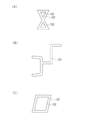
- FIG. 13 (A), FIG. 13 (B), and FIG. 13 (C) are diagrams showing examples of the shapes of other welded portions.
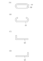
- 14 (A), FIG. 14 (B), FIG. 14 (C), and FIG. 14 (D) are diagrams showing examples of shapes of other welded portions.
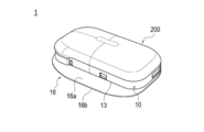
- FIG. 1 is an exploded perspective view of a drug solution administration device (medical device) 1 according to the present embodiment
- FIGS. 2 and 3 are perspective views of the drug solution administration device (medical device) 1
- FIGS. 4 and 5 are housings. 10 and the puncture device 35
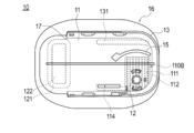
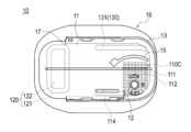
- FIG. 6 is a plan view of the housing 10.
- the drug solution administration device 1 is configured as a portable insulin administration device that delivers insulin as a drug solution into the living body of a diabetic patient who is a user.
- the drug solution is not limited to insulin and may be another drug solution.
- the drug solution administration device 1 is outlined, and a housing 10 that can be attached to a living body and a bottom surface (corresponding to one surface) 11b arranged on the living body side in the housing 10. It has a sheet-shaped adhering portion 16 provided in the housing, and a fixing region 110 in which the housing 10 and the adhering portion 16 are fixed.
- the housing 10 has a fitting hole 12 (corresponding to a hole portion) formed on the bottom surface 11b of the housing 10 and penetrating the bottom surface.
- the adhesion part 16 has an adhesion part 16c formed on at least a part of a bottom surface 16b (corresponding to one surface) arranged facing the living body.
- the fixing region 110 has a welded portion 111 formed near the fitting hole 12 and a non-welded portion 112 formed at a position adjacent to the welded portion 111. There is.
- the drug solution administration device 1 has a liquid delivery mechanism 200 configured to be connectable to and detachable from the housing 10.
- the liquid feeding mechanism 200 is not particularly limited as long as it can feed a drug solution into a living body, but for example, a reuse mechanism including a drive mechanism 211 for generating a driving force for driving a member necessary for the liquid feeding operation. It is possible to use a unit that includes the unit 210 and the drug solution storage unit 221 filled with insulin, and the like, and includes the reuse unit 210 and the disposable unit 220 that can be connected and separated. As shown in FIGS. 2 and 3, the user can connect the liquid delivery mechanism 200 to the housing 10 in a state where the reuse section 210 and the disposable section 220 are connected.
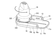
- ⁇ Puncture device> 4 and 5 show the lancing device 35.
- the puncture device 35 is used for connecting the administration port portion 30 for delivering the drug solution into the living body to the housing 10 and for puncturing the puncture needle 20 (see FIG. 3) punctured by the living body. ..
- the user connects the administration port unit 30 to the housing 10 using the lancing device 35 before connecting the liquid feeding mechanism 200 to the housing 10.
- the administration port portion 30 is fixed by being fitted into the fitting hole 12 (see FIG. 6) of the housing 10.
- the user uses the puncture device 35 to project the puncture needle 20 from the bottom surface 11b side of the housing 10 and puncture the living body with the puncture needle 20.
- the puncture needle 20 can be configured by, for example, a double needle including a cannula having a lumen formed therein and an inner needle inserted through the cannula.
- the puncture device 35 is configured so that the administration port portion 30 can be connected to the housing 10 and the puncture needle 20 can be projected by a relative rotation operation with respect to the housing 10.
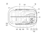
- the puncture device 35 includes a first guide portion 310, a second guide portion 320, and a third guide portion for guiding the operation of the puncture device 35 when rotating the puncture device 35. It has 330.
- the side wall 13 of the housing 10 is formed with a first hole portion 14a through which the first guide portion 310 is inserted and a second hole portion 14b through which the second guide portion 320 is inserted.
- the bottom portion 11 of the housing 10 is formed with a third hole portion 15 into which the third guide portion 330 is inserted.
- the guide parts 310, 320, 330 are inserted into and engaged with the hole parts 14a, 14b, 15 when the puncture device 35 is rotated.
- the user can guide the rotation of the puncture device 35 by the respective guide portions 310, 320, 330 while rotating the puncture device 35. Therefore, the user can rotate the lancing device 35 in parallel to the bottom portion 11 of the housing 10.
- FIG. 5 after the puncture device 35 is rotated by a certain amount, the engagement between the hole portions 14a, 14b, 15 and the guide portions 310, 320, 330 is released.
- the user can separate the puncture device 35 from the housing 10 by lifting the puncture device 35 after the holes 14a, 14b, 15 and the guide parts 310, 320, 330 are disengaged. ..
- the lancing device 35 can be provided in a state in which it is connected to the housing 10 before the liquid supply mechanism 200 is connected to the housing 10.
- the user attaches the housing 10 to the surface of the user's living body by using the attachment portion 16 formed on the housing 10.
- the user uses the puncture device 35 to connect the administration port section 30 to the housing 10 and puncture the living body with the puncture needle 20 while the housing 10 is attached to the surface of the living body.
- the user After separating the puncture device 35 from the housing 10, the user connects the liquid delivery mechanism 200 to the housing 10 as shown in FIGS. 2 and 3.
- the user When connecting the liquid delivery mechanism 200 to the housing 10, the user fluidly connects the administration port section 30, the cannula of the puncture needle 20, and the drug solution storage section 221.
- the user can administer the drug solution into the living body by operating a predetermined controller to drive the drive mechanism 211.
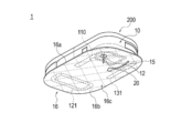
- the housing 10 includes a bottom portion 11 attached to a living body via an attachment portion 16, a side wall 13 surrounding a part of the periphery of the bottom portion 11, and a liquid feeding mechanism 200 in the housing 10. It has an insertion portion 17 for inserting the liquid feeding mechanism 200 into the housing 10 when connecting.
- the bottom portion 11 has a mounting surface (top surface) 11a on which the liquid delivery mechanism 200 can be mounted, a bottom surface 11b located on the back surface side of the mounting surface 11a, and an administration port portion 30. It has a possible fitting hole (hole portion) 12 and a third hole portion 15 into which the third guide portion 330 of the lancing device 35 is inserted.
- the housing 10 has a substantially elliptical planar shape.
- the fitting hole 12 has a substantially circular planar shape.
- the insertion portion 17 is formed by an opening formed by cutting out a part of the side wall 13.
- the third hole 15 has a planar shape that extends in a substantially arc shape along the longitudinal direction of the housing 10 (the left-right direction in FIG. 6).
- the housing 10 can be made of, for example, a resin material such as polypropylene, polyethylene terephthalate, polymethylmethacrylate, or polycarbonate.
- the fitting hole 12 penetrates the bottom portion 11 of the housing 10 in the thickness direction.
- the third hole portion 15 penetrates the bottom portion 11 of the housing 10 in the thickness direction.
- the insertion portion 17 is formed on the other end side opposite to the one end in the longitudinal direction of the housing 10 in which the fitting hole 12 is arranged.
- the attachment portion 16 is formed on the top surface 16a arranged on the bottom surface 11b side of the housing 10, the bottom surface 16b located on the back surface side of the top surface 16a, and the bottom surface 16b.
- Adhesive portion 16c illustrated by hatching in FIG. 3).
- the adhesion part 16 is formed larger than the housing 10 so as to protrude from the outer periphery of the housing 10 in the plan view shown in FIG. 6.
- the upper surface 16 a of the attachment portion 16 is fixed to the bottom surface 11 b of the housing 10 by welding. With such a structure, the adhesive area is increased, peeling that occurs from the outer periphery of the housing 10 can be prevented, and the state in which the housing 10 is mounted on the living body surface can be stably maintained.
- a hole for inserting the puncture needle 20 is formed in the attachment portion 16 at a position corresponding to the fitting hole 12 of the housing 10. Further, a hole portion for inserting the third guide portion 330 of the puncture device 35 is formed in a portion of the attachment portion 16 corresponding to the third hole portion 15 of the housing 10.
- the adhesive part 16 can be configured by an adhesive member (single-sided adhesive type tape) having a sheet-shaped base material and an adhesive part 16c provided on the bottom surface of the base material (bottom surface 16b of the adhesive part 16).
- the base material can be made of, for example, a polyethylene film, a polyester non-woven fabric, a rayon non-woven fabric, a resin-coated cotton fabric, or the like.
- the adhesive section 16c can be made of an adhesive such as an acrylic adhesive, a silicone adhesive, or a gel adhesive.
- the attachment portion 16 may be provided with a release paper or the like that covers the bottom surface 16b of the attachment portion 16 until the housing 10 is attached to the living body.
- the attachment part 16 is not limited to a single-sided tape, and may be formed of a double-sided tape or an adhesive applied to a base material, but it is more preferable to use a single-sided adhesive type tape because of the structure protruding from the outer periphery of the housing 10. ..
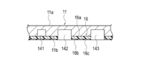
- a welding portion 111 and a non-welding portion 112 are arranged in the fixing region 110 so as to surround the periphery of the fitting hole 12.
- the welded portions 111 and the non-welded portions 112 are arranged alternately along the outer periphery of the fitting hole 12.
- the welded portion 111 means a portion (a portion indicated by a broken line in FIG. 6) where the housing 10 and the attachment portion 16 are welded in the fixed region 110, and the non-welded portion 112 is the fixed region 110. In, it means a portion (area) where the housing 10 and the attachment portion 16 are not welded.
- other welded portions 113 and 114 may be formed in the fixed region 110 in close proximity to each other.
- the welded portion 113 extends so as to connect the linear welded portions 111 around the fitting hole 12.
- the welded portion 113 extends from the fitting hole 12 to the vicinity of the third hole portion 15.
- a welded portion (corresponding to an auxiliary welded portion) 114 extends from the welded portion 111 in a substantially linear shape along the longitudinal direction of the housing 10.
- the welded portions 113 and 114 may be formed so as to be continuously connected to the welded portion 111, or may not be formed so as to be connected to the welded portion 111.
- the welded portion 111 is formed in four linear patterns that extend radially from the fitting hole 12.
- the non-welded portion 112 formed between the welded portions 111 has a substantially triangular planar shape surrounded by the welded portions 111 and 113.
- the patterns of the welded portions 111, 113, 114 and the shape of the non-welded portion 112 are not particularly limited.
- the portion of the housing 10 where the fitting hole 12 is formed cannot be welded. Therefore, in the vicinity of the fitting hole 12, the fixing force between the attachment portion 16 and the housing 10 is reduced. As a measure against such a problem, it is considered that the fixing force between the attachment portion 16 and the housing 10 can be improved by forming the welded portion so as to surround the entire circumference of the fitting hole 12.
- the adhesion part 16c is affected by the heat applied when forming the welded part, the adhesion part 16c has a reduced adhesive force.
- the housing 10 when the housing 10 is mounted on the surface of the living body of the user, it may not be possible to stably maintain the state in which the housing 10 is mounted on the surface of the living body via the attachment portion 16. Further, when the fixing force between the attachment portion 16 and the housing 10 and / or the adhesive force of the adhesive portion 16c decreases near the fitting hole 12, the puncture needle 20 punctured into the living body may be pulled out or the administration port may be removed. There is a possibility of causing a problem that the fluid communication is disconnected at the connection portion that is the portion 30.
- both the welded portion 111 and the non-welded portion 112 are formed around the fitting hole 12 in the fixed region 110, so that the housing 10 and the attachment portion 16 are fixed to each other. It is possible to suppress the significant decrease in the adhesive force of the adhesive portion 16c of the attaching portion 16 while increasing the fixing force to be applied.
- the drug solution administration device 1 further includes a welded portion (corresponding to another welded portion) 121 in which the housing 10 and the attachment portion 16 are welded in the vicinity of the insertion portion 17.
- a welded portion corresponding to another welded portion
- the drug solution administration device 1 can suitably prevent the fixation between the housing 10 and the attachment portion 16 near the insertion portion 17 from being released. Further, the welding portion 121 can prevent the housing 10 and the attachment portion 16 from being separated from each other when the liquid feeding mechanism 200 is removed from the housing 10.
- the welded portion 121 is formed in a frame shape in a direction intersecting the longitudinal direction of the housing 10.
- a non-welded portion 122 is formed in a region surrounded by the welded portion 121. Specific shapes of the welded portion 121 and the non-welded portion 122 are not particularly limited.
- the drug solution administration device 1 further includes a welded portion 131 formed on the side wall 13 side (outer peripheral side of the housing 10) with respect to the third hole 15.
- the welded portion 131 extends along the longitudinal direction of the housing 10.
- the fixing region 110 is preferably formed, for example, in the range of 0 to 50% of the entire length of the housing 10 from one end of the housing 10 (the end on the right side in FIG. 6) along the longitudinal direction of the housing 10.
- the welded portion 121 may be formed, for example, in the range of 10 to 40% of the entire length of the housing 10 along the longitudinal direction of the housing 10 from the other end (the left end in FIG. 6) of the housing 10. Preferably, it is more preferably formed in the range of 15% to 35%.
- the adhesive force of the adhesive section 16c of the adhered section 16 is larger than that of other areas.
- the welding portion 131 can be formed in the same range as the fixing region 110.
- each welded portion 111, 113, 114, 121, 131 can be formed by continuously connecting arbitrary welded portions. Further, other welded portions (for example, welded portions extending linearly in the longitudinal direction of the housing 10 or a direction intersecting the longitudinal direction) which are not shown are formed, and the above-mentioned welded portions 111 are formed via the welded portions. , 113, 114, 121, 131 may be selectively connected.
- each of the welded portions 111, 113, 114, 121, 131 is not particularly limited, but examples thereof include heat welding by embossing, ultrasonic welding, laser welding, vibration welding (horn welding), hot air, spin welding, and the like. It can be carried out by a known method.
- the welded portions 111, 113, 114, 121, 131 are formed by heat welding, since a mold for applying heat is used, it is possible to perform welding with high reproducibility in alignment. Also, the welding pattern can be easily changed by changing the mold. Thereby, various patterns of welding can be performed according to the housing 10.
- the housing 10 that can be attached to a living body, the sheet-shaped attachment portion 16 provided on the bottom surface 11b of the housing 10, and the housing 10 and the attachment portion 16 are fixed. And a fixed region 110.
- the housing 10 has a fitting hole 12 formed on the bottom surface 11b of the housing 10 and penetrating the bottom surface 11b.
- the adhesion part 16 has an adhesion part 16c formed on at least a part of the bottom surface 16b of the adhesion part 16.
- the fixing region 110 has a welded portion 111 formed near the fitting hole 12, and a non-welded portion 112 formed at a position adjacent to the welded portion 111.
- the fixing force between the adhesion part 16 and the housing 10 can be increased by the welding part 111 included in the fixing region 110. Further, the non-welded portion 112 included in the fixed region 110 can prevent the adhesive force of the adhesive portion 16c in the fixed region 110 from being excessively reduced. Therefore, in the drug solution administration device 1, the fixing force between the housing 10 and the attachment portion 16 and the adhesive force between the attachment portion 16 and the living body surface are enhanced.
- the fixing region 110 is arranged so as to surround the periphery of the fitting hole 12, and the welding portion 111 and the non-welding portion 112 are arranged alternately along the outer periphery of the fitting hole 12. Since both the welded portion 111 and the non-welded portion 112 are formed around the fitting hole 12 in the fixing region 110, the fixing force for fixing the housing 10 and the adhering portion 16 is increased, while the adhering portion 16 is fixed. It is possible to suppress a significant decrease in the adhesive force of the adhesive portion 16c. This maintains the fixing force between the housing 10 and the attachment portion 16 and the adhesive force between the attachment portion 16 and the living body surface in the vicinity of the fitting hole 12, thereby puncturing the living body with the puncture needle 20. Will be more certain.
- the housing 10 further includes a welded portion 113 formed at a position different from the welded portion 111 along one direction of the housing 10. Therefore, the fixing force between the housing 10 and the attachment portion 16 can be further increased.
- the housing 10 has an insertion portion 17 for inserting the liquid feeding mechanism 200 connected to the housing 10 into the housing 10.
- the housing 10 has a welding portion 121 in which the housing 10 and the attachment portion 16 are welded near the insertion portion 17. Therefore, when the liquid delivery mechanism 200 is attached to and detached from the housing 10, it is possible to prevent the attachment portion 16 from peeling off from the housing 10 and the attachment portion 16 from being twisted.
- the pattern (shape) of the welded portion 111 and the non-welded portion 112 included in the fixed region 110 is not limited to the pattern shown in FIG.
- the welded portion 111 and the non-welded portion 112 may be formed in the fixed region 110A in parallel linear patterns spaced from each other.
- the welded portion 111 and the non-welded portion 112 can be formed, for example, in a shape that extends linearly in the longitudinal direction of the housing 10 (the left-right direction in FIG. 7).
- the welded portion 111 and the non-welded portion 112 are formed in the fixing region 110B so as to extend linearly in the direction intersecting the longitudinal direction of the housing 10 (the vertical direction in FIG. 8). May be.
- the welded portion 111 and the non-welded portion 112 may be formed in a grid pattern that intersects with each other in the fixed region 110C.
- the groove portions 142 and 143 that reduce the contact area between the living body surface and the bottom surface 11b of the housing 10 may be formed.
- the passage 141 prevents air from flowing toward the bottom surface 11b of the housing 10 to increase humidity between the housing 10 and the surface of the living body, thereby preventing the user from feeling uncomfortable.
- the groove portions 142 and 143 can reduce the contact area between the living body surface and the bottom surface 11b of the housing 10 to reduce the influence of the adhesive portion 16c on the user's skin.
- a vent hole 145 penetrating the bottom portion 11 of the housing 10 may be formed.
- the vent holes 145 it becomes possible to release water vapor and the like from between the housing 10 and the surface of the living body, so that it is possible to reduce the influence on the user's skin.
- each groove 142, 143, the vent hole 145, etc. in the region of the housing 10 where the welded portions 111, 113, 114, 121, 131 are not formed, the adhesive portion 16c in the above region is formed. It is possible to adjust the size of the adhesive force of.
- Each of the groove portions 142 and 143 can be formed by blast processing, surface processing with a mold, or the like.
- the passage 141 can be formed by surface processing using a mold or the like.
- the specific shapes and positions of the passage 141, the groove portions 142 and 143, and the ventilation hole 145 are not limited to those illustrated in the drawings.
- the pattern (shape) of the welded portion 121 formed near the insertion portion 17 is not limited to the pattern shown in FIG.
- the welded portion 121 may have, for example, as shown in FIG. 13A, a pattern in which two triangular shapes in which a non-welded portion 122 is formed are connected.
- the welded portion 121 may have a pattern of geometric shapes continuously connected.
- the welded portion 121 may have a rhombic pattern.
- the welded portion 121 may have an elliptical pattern.
- the welded portion 121 may have a pattern in which a part of the ellipse is missing.
- the welded portion 121 may have an L-shaped pattern.
- the medical liquid administration device is given as an example of application of the medical device according to the present invention, but the medical device is not limited to the medical liquid administration device.
- the medical device may be, for example, an inspection device including an inspection unit that is inserted into the living body.
- the fixing region can be arranged around an insertion portion (a hole or the like) formed in the housing for inserting the inspection portion into a living body.
- 1 drug administration device (medical equipment), 10 housing, 11 bottom, 11a mounting surface 11b bottom surface (one surface), 12 Fitting holes (holes), 13 side walls, 16 Attached part, 16a upper surface 16b bottom surface (one surface), 16c adhesive part, 17 Insert, 20 puncture needle, 30 administration port section, 35 lancing device, 110, 110A, 110B, 110C fixed area, 111 welded part, 112 non-welded part, 113 Other welded parts, 114 other welded parts, 121 Other welded parts, 122 non-welded part, 131 Other welded parts, 141 passage, 142, 143 groove, 145 vents.
Abstract
The present invention can provide a medical device capable of enhancing the securing force between a housing and an adhesion part and the adhesion between the adhesion part and a living body surface. A drug solution administration device (1) comprises: a housing (10) that can be attached to a living body; a sheet-shaped adhesion part (16) provided on a bottom surface (11b) which is located on a living body side in the housing; and a securing region (110) in which the housing and the adhesion part are secured. The housing has an engagement hole (12) which is formed in the bottom surface thereof to pass through the bottom surface. The adhesion part has an adhesive part (16c) formed in at least a portion of the bottom surface (16b), which is to be disposed to face the living body. The securing region has a fused section (111) formed near the hole and a non-fused section (112) formed at a position adjacent to the fused section.
Description
本発明は、医療機器に関する。
The present invention relates to medical devices.
従来から、インスリンなどの薬液を投与する装置として、投与対象となる患者や被検者の皮膚に取り付けられた状態で連続的または間欠的に薬液を投与する携帯型の薬液投与装置が知られている(例えば、特許文献1を参照)。
BACKGROUND ART Conventionally, as a device that administers a drug solution such as insulin, a portable drug solution administration device that continuously or intermittently administers a drug solution attached to the skin of a patient or subject to be administered has been known. (For example, see Patent Document 1).
上述した薬液投与装置では、薬液投与装置が備えるハウジングの生体表面に向かい合わせて配置される面(例えば、底面)には、生体に当該装置を装着した状態を保持するための付着部(粘着部)が設けられている。
In the above-described drug administration device, the surface (for example, the bottom surface) of the housing of the drug administration device that faces the living body surface has an attachment portion (adhesive portion) for holding the state where the device is attached to the living body. ) Is provided.
ハウジングに付着部を形成する場合、例えば、ハウジング側に配置される面および生体表面側に配置される面の両面に粘着面が形成された粘着テープを使用することができる。ただし、粘着テープを使用する場合、粘着テープの粘着力だけでは、ハウジングと粘着テープとの間の固定力を維持することができない可能性がある。このような課題の解決を図るために、例えば、粘着テープをハウジングに対して溶着固定する方法が考えられる。
When forming the adhesion part on the housing, for example, an adhesive tape having adhesive surfaces formed on both the surface arranged on the housing side and the surface arranged on the living body surface side can be used. However, when an adhesive tape is used, the adhesive force of the adhesive tape alone may not be able to maintain the fixing force between the housing and the adhesive tape. In order to solve such a problem, for example, a method of welding and fixing an adhesive tape to a housing can be considered.
しかしながら、粘着テープをハウジングに対して溶着固定した場合、粘着テープが溶着固定された部分では、溶着時に発生する熱の影響により、生体表面との粘着力が低下してしまう可能性がある。また、ハウジングには、ハウジングを貫通する孔などが形成されるが、このような孔の周囲では、ハウジングと粘着テープの接触面積を大きく確保することが難しいため、粘着テープがハウジングから外れ易くなってしまう。
However, when the adhesive tape is welded and fixed to the housing, the adhesive force with the surface of the living body may be reduced in the portion where the adhesive tape is welded and fixed due to the effect of heat generated during welding. In addition, a hole or the like penetrating the housing is formed in the housing. However, since it is difficult to secure a large contact area between the housing and the adhesive tape around the hole, the adhesive tape easily comes off from the housing. Will end up.
本発明の目的は、ハウジングと付着部との間の固定力および付着部と生体表面との間の接着力を高めることができる医療機器を提供することにある。
An object of the present invention is to provide a medical device capable of increasing the fixing force between the housing and the attachment portion and the adhesive force between the attachment portion and the living body surface.
上記目的を達成するための本発明に係る医療機器は、生体に装着可能なハウジングと、ハウジングにおいて生体側に配置される一の面に設けられたシート状の付着部と、前記ハウジングと前記付着部とが固定された固定領域と、を有し、前記ハウジングは、前記ハウジングの前記一の面に形成され、前記一の面を貫通する孔部を有し、前記付着部は、前記生体に向かい合わせて配置される面の少なくとも一部に形成された粘着部を有し、前記固定領域は、前記孔部付近に形成された溶着部と、前記溶着部に隣接した位置に形成された非溶着部と、を有する。
MEANS TO SOLVE THE PROBLEM The medical device which concerns on this invention for achieving the said object is a housing which can be mounted | worn with a living body, the sheet-shaped attachment part provided in one surface arrange | positioned at the living body side in a housing, the said housing and the said attachment And a fixing region in which the part is fixed, the housing has a hole formed in the one surface of the housing, and the hole penetrates the one surface, and the attachment part is attached to the living body. The adhesive region is formed on at least a part of the surfaces arranged to face each other, and the fixing region includes a welding portion formed near the hole portion and a non-adhesive portion formed at a position adjacent to the welding portion. And a welded portion.
本発明によれば、ハウジングと付着部との間の固定力および付着部と生体表面との間の粘着力が高められた医療機器を提供することができる。
According to the present invention, it is possible to provide a medical device in which the fixing force between the housing and the attachment portion and the adhesive force between the attachment portion and the living body surface are enhanced.
以下、添付した図面を参照しながら、本発明の実施形態を説明する。なお、以下の記載は特許請求の範囲に記載される技術的範囲や用語の意義を限定するものではない。また、図面の寸法比率は説明の都合上誇張されており、実際の比率とは異なる場合がある。
Hereinafter, embodiments of the present invention will be described with reference to the accompanying drawings. Note that the following description does not limit the technical scope or the meaning of terms used in the claims. Further, the dimensional ratios in the drawings are exaggerated for convenience of description, and may differ from the actual ratios.
図1は本実施形態に係る薬液投与装置(医療機器)1の分解斜視図であり、図2、図3は、薬液投与装置(医療機器)1の斜視図、図4、図5は、ハウジング10および穿刺装置35を示す図、図6はハウジング10の平面図である。
FIG. 1 is an exploded perspective view of a drug solution administration device (medical device) 1 according to the present embodiment, FIGS. 2 and 3 are perspective views of the drug solution administration device (medical device) 1, and FIGS. 4 and 5 are housings. 10 and the puncture device 35, and FIG. 6 is a plan view of the housing 10.
図1に示すように、薬液投与装置1は、使用者である糖尿病患者の生体内に薬液としてインスリンを送液する携帯型のインスリン投与装置として構成している。なお、薬液はインスリンに限定されることはなく、他の薬液であってもよい。
As shown in FIG. 1, the drug solution administration device 1 is configured as a portable insulin administration device that delivers insulin as a drug solution into the living body of a diabetic patient who is a user. The drug solution is not limited to insulin and may be another drug solution.
図1、図3、図6に示すように、薬液投与装置1は、概説すると、生体に装着可能なハウジング10と、ハウジング10において生体側に配置される底面(一の面に相当する)11bに設けられたシート状の付着部16と、ハウジング10と付着部16とが固定された固定領域110と、を有している。
As shown in FIG. 1, FIG. 3, and FIG. 6, the drug solution administration device 1 is outlined, and a housing 10 that can be attached to a living body and a bottom surface (corresponding to one surface) 11b arranged on the living body side in the housing 10. It has a sheet-shaped adhering portion 16 provided in the housing, and a fixing region 110 in which the housing 10 and the adhering portion 16 are fixed.
また、ハウジング10は、ハウジング10の底面11bに形成され、底面を貫通する嵌合孔12(孔部に相当する)を有している。付着部16は、生体に向かい合わせて配置される底面16b(一の面に相当する)の少なくとも一部に形成された粘着部16cを有している。固定領域110は、図3、図6に示すように、嵌合孔12付近に形成された溶着部111と、溶着部111に隣接した位置に形成された非溶着部112と、を有している。
Further, the housing 10 has a fitting hole 12 (corresponding to a hole portion) formed on the bottom surface 11b of the housing 10 and penetrating the bottom surface. The adhesion part 16 has an adhesion part 16c formed on at least a part of a bottom surface 16b (corresponding to one surface) arranged facing the living body. As shown in FIGS. 3 and 6, the fixing region 110 has a welded portion 111 formed near the fitting hole 12 and a non-welded portion 112 formed at a position adjacent to the welded portion 111. There is.
<薬液投与装置>
図1に示すように、薬液投与装置1は、ハウジング10と接続および分離可能に構成された送液機構200を有している。 <Medicinal solution administration device>
As shown in FIG. 1, the drugsolution administration device 1 has a liquid delivery mechanism 200 configured to be connectable to and detachable from the housing 10.
図1に示すように、薬液投与装置1は、ハウジング10と接続および分離可能に構成された送液機構200を有している。 <Medicinal solution administration device>
As shown in FIG. 1, the drug
送液機構200としては、生体内へ薬液を送液することが可能な限り特に制限はないが、例えば、送液動作に必要な部材を駆動させる駆動力を生じさせる駆動機構211等を含むリユース部210およびインスリンが充填された薬液貯蔵部221等を含み、リユース部210と接続分離可能なディスポーザブル部220と、を有するものを使用することができる。図2、図3に示すように、使用者は、リユース部210とディスポーザブル部220とを接続した状態で、ハウジング10に送液機構200を接続することができる。
The liquid feeding mechanism 200 is not particularly limited as long as it can feed a drug solution into a living body, but for example, a reuse mechanism including a drive mechanism 211 for generating a driving force for driving a member necessary for the liquid feeding operation. It is possible to use a unit that includes the unit 210 and the drug solution storage unit 221 filled with insulin, and the like, and includes the reuse unit 210 and the disposable unit 220 that can be connected and separated. As shown in FIGS. 2 and 3, the user can connect the liquid delivery mechanism 200 to the housing 10 in a state where the reuse section 210 and the disposable section 220 are connected.
<穿刺装置>
図4、図5には、穿刺装置35を示す。穿刺装置35は、薬液を生体内へ送液するための投与ポート部30をハウジング10に接続する作業、および生体に穿刺される穿刺針20(図3を参照)を穿刺するために使用される。 <Puncture device>
4 and 5 show thelancing device 35. The puncture device 35 is used for connecting the administration port portion 30 for delivering the drug solution into the living body to the housing 10 and for puncturing the puncture needle 20 (see FIG. 3) punctured by the living body. ..
図4、図5には、穿刺装置35を示す。穿刺装置35は、薬液を生体内へ送液するための投与ポート部30をハウジング10に接続する作業、および生体に穿刺される穿刺針20(図3を参照)を穿刺するために使用される。 <Puncture device>
4 and 5 show the
図4、図5に示すように、使用者は、送液機構200をハウジング10に接続する前に、穿刺装置35を使用して、ハウジング10に投与ポート部30を接続する。投与ポート部30は、ハウジング10の嵌合孔12(図6を参照)に嵌合することで固定される。また、使用者は、穿刺装置35を使用して、ハウジング10の底面11b側から穿刺針20を突出させ、穿刺針20を生体に穿刺する。穿刺針20は、例えば、内腔が形成されたカニューレおよびカニューレに挿通された内針からなる二重針で構成することができる。
As shown in FIGS. 4 and 5, the user connects the administration port unit 30 to the housing 10 using the lancing device 35 before connecting the liquid feeding mechanism 200 to the housing 10. The administration port portion 30 is fixed by being fitted into the fitting hole 12 (see FIG. 6) of the housing 10. Further, the user uses the puncture device 35 to project the puncture needle 20 from the bottom surface 11b side of the housing 10 and puncture the living body with the puncture needle 20. The puncture needle 20 can be configured by, for example, a double needle including a cannula having a lumen formed therein and an inner needle inserted through the cannula.
穿刺装置35は、図4、図5に示すように、ハウジング10に対する相対的な回転操作によりハウジング10に対する投与ポート部30の接続と穿刺針20の突出とを実施可能に構成している。
As shown in FIGS. 4 and 5, the puncture device 35 is configured so that the administration port portion 30 can be connected to the housing 10 and the puncture needle 20 can be projected by a relative rotation operation with respect to the housing 10.
穿刺装置35は、図4、図5に示すように、穿刺装置35を回転させる際、穿刺装置35の動作をガイドするための第1ガイド部310、第2ガイド部320、および第3ガイド部330を有している。ハウジング10の側壁13には、第1ガイド部310が挿通される第1孔部14aと、第2ガイド部320が挿通される第2孔部14bが形成されている。ハウジング10の底部11には、第3ガイド部330が挿通される第3孔部15が形成されている。
As shown in FIGS. 4 and 5, the puncture device 35 includes a first guide portion 310, a second guide portion 320, and a third guide portion for guiding the operation of the puncture device 35 when rotating the puncture device 35. It has 330. The side wall 13 of the housing 10 is formed with a first hole portion 14a through which the first guide portion 310 is inserted and a second hole portion 14b through which the second guide portion 320 is inserted. The bottom portion 11 of the housing 10 is formed with a third hole portion 15 into which the third guide portion 330 is inserted.
穿刺装置35は、穿刺装置35を回転させる際、各孔部14a、14b、15に各ガイド部310、320、330を挿入して係合される。使用者は、図4に示すように、穿刺装置35を回転させている間は、各ガイド部310、320、330により穿刺装置35の回転をガイドすることができる。そのため、使用者は、穿刺装置35をハウジング10の底部11に対して平行に回転させることができる。また、図5に示すように、穿刺装置35を一定量だけ回転させた後は、各孔部14a、14b、15と各ガイド部310、320、330の係合が解除される。使用者は、各孔部14a、14b、15と各ガイド部310、320、330の係合が解除された後、穿刺装置35を持ち上げることにより、ハウジング10から穿刺装置35を分離させることができる。
When the puncture device 35 is rotated, the guide parts 310, 320, 330 are inserted into and engaged with the hole parts 14a, 14b, 15 when the puncture device 35 is rotated. As shown in FIG. 4, the user can guide the rotation of the puncture device 35 by the respective guide portions 310, 320, 330 while rotating the puncture device 35. Therefore, the user can rotate the lancing device 35 in parallel to the bottom portion 11 of the housing 10. Further, as shown in FIG. 5, after the puncture device 35 is rotated by a certain amount, the engagement between the hole portions 14a, 14b, 15 and the guide portions 310, 320, 330 is released. The user can separate the puncture device 35 from the housing 10 by lifting the puncture device 35 after the holes 14a, 14b, 15 and the guide parts 310, 320, 330 are disengaged. ..
穿刺装置35は、ハウジング10に送液機構200を接続する前の状態において、ハウジング10に接続した状態で提供することができる。使用者は、ハウジング10に形成された付着部16を使用してハウジング10を使用者の生体表面に装着する。使用者は、ハウジング10を生体表面に装着した状態で、穿刺装置35を使用して投与ポート部30をハウジング10に接続するとともに穿刺針20を生体に穿刺する。使用者は、穿刺装置35をハウジング10から分離させた後、図2、図3に示すように、ハウジング10に送液機構200を接続する。使用者は、送液機構200をハウジング10に接続する際、投与ポート部30、穿刺針20のカニューレ、薬液貯蔵部221を流体連通させる。使用者は、所定のコントローラを操作して、駆動機構211を駆動させることにより、生体内に薬液を投与することができる。
The lancing device 35 can be provided in a state in which it is connected to the housing 10 before the liquid supply mechanism 200 is connected to the housing 10. The user attaches the housing 10 to the surface of the user's living body by using the attachment portion 16 formed on the housing 10. The user uses the puncture device 35 to connect the administration port section 30 to the housing 10 and puncture the living body with the puncture needle 20 while the housing 10 is attached to the surface of the living body. After separating the puncture device 35 from the housing 10, the user connects the liquid delivery mechanism 200 to the housing 10 as shown in FIGS. 2 and 3. When connecting the liquid delivery mechanism 200 to the housing 10, the user fluidly connects the administration port section 30, the cannula of the puncture needle 20, and the drug solution storage section 221. The user can administer the drug solution into the living body by operating a predetermined controller to drive the drive mechanism 211.
<ハウジング>
図1、図6に示すように、ハウジング10は、付着部16を介して生体に装着される底部11と、底部11の周囲の一部を囲む側壁13と、ハウジング10に送液機構200を接続する際、送液機構200をハウジング10内に挿入するための挿入部17と、を有している。 <Housing>
As shown in FIGS. 1 and 6, thehousing 10 includes a bottom portion 11 attached to a living body via an attachment portion 16, a side wall 13 surrounding a part of the periphery of the bottom portion 11, and a liquid feeding mechanism 200 in the housing 10. It has an insertion portion 17 for inserting the liquid feeding mechanism 200 into the housing 10 when connecting.
図1、図6に示すように、ハウジング10は、付着部16を介して生体に装着される底部11と、底部11の周囲の一部を囲む側壁13と、ハウジング10に送液機構200を接続する際、送液機構200をハウジング10内に挿入するための挿入部17と、を有している。 <Housing>
As shown in FIGS. 1 and 6, the
底部11は、図6に示すように、送液機構200を載置可能な載置面(上面)11aと、載置面11aの裏面側に位置する底面11bと、投与ポート部30が嵌合可能な嵌合孔(孔部)12と、穿刺装置35の第3ガイド部330が挿入される第3孔部15と、を有している。
As shown in FIG. 6, the bottom portion 11 has a mounting surface (top surface) 11a on which the liquid delivery mechanism 200 can be mounted, a bottom surface 11b located on the back surface side of the mounting surface 11a, and an administration port portion 30. It has a possible fitting hole (hole portion) 12 and a third hole portion 15 into which the third guide portion 330 of the lancing device 35 is inserted.
ハウジング10は、略楕円形の平面形状を有している。嵌合孔12は、略円形の平面形状を有している。挿入部17は、側壁13の一部を切り欠いて形成した開口部により構成している。第3孔部15は、ハウジング10の長手方向(図6の左右方向)に沿って略円弧状に延びた平面形状を有している。ハウジング10は、例えば、ポリプロピレン、ポリエチレンテレフタレート、ポリメチルメタクリレート、ポリカーボネート等の樹脂材料で形成することができる。
The housing 10 has a substantially elliptical planar shape. The fitting hole 12 has a substantially circular planar shape. The insertion portion 17 is formed by an opening formed by cutting out a part of the side wall 13. The third hole 15 has a planar shape that extends in a substantially arc shape along the longitudinal direction of the housing 10 (the left-right direction in FIG. 6). The housing 10 can be made of, for example, a resin material such as polypropylene, polyethylene terephthalate, polymethylmethacrylate, or polycarbonate.
嵌合孔12は、ハウジング10の底部11を厚み方向に貫通している。同様に、第3孔部15は、ハウジング10の底部11を厚み方向に貫通している。
The fitting hole 12 penetrates the bottom portion 11 of the housing 10 in the thickness direction. Similarly, the third hole portion 15 penetrates the bottom portion 11 of the housing 10 in the thickness direction.
挿入部17は、図6に示すように、嵌合孔12が配置されたハウジング10の長手方向の一端部と反対側の他端部側に形成されている。
As shown in FIG. 6, the insertion portion 17 is formed on the other end side opposite to the one end in the longitudinal direction of the housing 10 in which the fitting hole 12 is arranged.
付着部16は、図2、図3、図6に示すように、ハウジング10の底面11b側に配置された上面16aと、上面16aの裏面側に位置する底面16bと、底面16bに形成された粘着部16c(図3において斜線で簡略的に図示する)と、を有している。
As shown in FIG. 2, FIG. 3, and FIG. 6, the attachment portion 16 is formed on the top surface 16a arranged on the bottom surface 11b side of the housing 10, the bottom surface 16b located on the back surface side of the top surface 16a, and the bottom surface 16b. Adhesive portion 16c (illustrated by hatching in FIG. 3).
付着部16は、図6に示す平面視において、ハウジング10の外周からはみ出るように、ハウジング10よりも大きく形成されている。付着部16は、付着部16の上面16aがハウジング10の底面11bに溶着により固定されている。このような構造により、粘着面積が広くなり、ハウジング10の外周から発生する剥がれを防止することができ、ハウジング10が生体表面に装着した状態を安定的に維持できる。
The adhesion part 16 is formed larger than the housing 10 so as to protrude from the outer periphery of the housing 10 in the plan view shown in FIG. 6. The upper surface 16 a of the attachment portion 16 is fixed to the bottom surface 11 b of the housing 10 by welding. With such a structure, the adhesive area is increased, peeling that occurs from the outer periphery of the housing 10 can be prevented, and the state in which the housing 10 is mounted on the living body surface can be stably maintained.
付着部16においてハウジング10の嵌合孔12に対応する箇所には、穿刺針20を挿通させるための孔部が形成されている。また、付着部16においてハウジング10の第3孔部15に対応する箇所には、穿刺装置35の第3ガイド部330を挿通させるための孔部が形成されている。
A hole for inserting the puncture needle 20 is formed in the attachment portion 16 at a position corresponding to the fitting hole 12 of the housing 10. Further, a hole portion for inserting the third guide portion 330 of the puncture device 35 is formed in a portion of the attachment portion 16 corresponding to the third hole portion 15 of the housing 10.
付着部16は、シート状の基材と、基材の底面(付着部16の底面16b)に設けられた粘着部16cとを有する接着部材(片面接着型のテープ)により構成することができる。基材は、例えば、ポリエチレンフィルム、ポリエステル不織布、レーヨン不織布、樹脂コーティング綿布等で構成することができる。また、粘着部16cは、例えば、アクリル系粘着剤、シリコン系粘着剤、ゲル粘着剤等の接着剤で構成することができる。付着部16には、ハウジング10を生体に装着する前の状態まで付着部16の底面16bを覆う剥離紙等を設けることができる。付着部16は、片面テープに限らず、両面テープや基材へ塗布した接着剤等によって構成されてもよいが、ハウジング10の外周からはみ出る構造により、片面接着型のテープを用いることがより好ましい。
The adhesive part 16 can be configured by an adhesive member (single-sided adhesive type tape) having a sheet-shaped base material and an adhesive part 16c provided on the bottom surface of the base material (bottom surface 16b of the adhesive part 16). The base material can be made of, for example, a polyethylene film, a polyester non-woven fabric, a rayon non-woven fabric, a resin-coated cotton fabric, or the like. The adhesive section 16c can be made of an adhesive such as an acrylic adhesive, a silicone adhesive, or a gel adhesive. The attachment portion 16 may be provided with a release paper or the like that covers the bottom surface 16b of the attachment portion 16 until the housing 10 is attached to the living body. The attachment part 16 is not limited to a single-sided tape, and may be formed of a double-sided tape or an adhesive applied to a base material, but it is more preferable to use a single-sided adhesive type tape because of the structure protruding from the outer periphery of the housing 10. ..
固定領域110には、図6に示すように、嵌合孔12の周囲を囲むように溶着部111および非溶着部112が配置されている。溶着部111と非溶着部112は、嵌合孔12の外周に沿って交互に配置されている。本明細書において、溶着部111は、固定領域110内においてハウジング10と付着部16とが溶着された箇所(図6において破線で示す箇所)を意味し、非溶着部112は、固定領域110内においてハウジング10と付着部16とが溶着されていない箇所(領域)を意味する。
As shown in FIG. 6, a welding portion 111 and a non-welding portion 112 are arranged in the fixing region 110 so as to surround the periphery of the fitting hole 12. The welded portions 111 and the non-welded portions 112 are arranged alternately along the outer periphery of the fitting hole 12. In the present specification, the welded portion 111 means a portion (a portion indicated by a broken line in FIG. 6) where the housing 10 and the attachment portion 16 are welded in the fixed region 110, and the non-welded portion 112 is the fixed region 110. In, it means a portion (area) where the housing 10 and the attachment portion 16 are not welded.
図6に示すように、固定領域110には、他の溶着部113、114が近接して形成されていてもよい。溶着部113は、線状の各溶着部111を嵌合孔12の周囲で繋げるように延びている。溶着部113は、嵌合孔12から第3孔部15付近まで延びている。また、溶着部(補助溶着部に相当する)114は、溶着部111からハウジング10の長手方向に沿って略直線状に延びている。なお、各溶着部113、114は、溶着部111と連続的に繋げて形成してもよいし、溶着部111と繋がって形成されていなくてもよい。
As shown in FIG. 6, other welded portions 113 and 114 may be formed in the fixed region 110 in close proximity to each other. The welded portion 113 extends so as to connect the linear welded portions 111 around the fitting hole 12. The welded portion 113 extends from the fitting hole 12 to the vicinity of the third hole portion 15. A welded portion (corresponding to an auxiliary welded portion) 114 extends from the welded portion 111 in a substantially linear shape along the longitudinal direction of the housing 10. The welded portions 113 and 114 may be formed so as to be continuously connected to the welded portion 111, or may not be formed so as to be connected to the welded portion 111.
固定領域110において、溶着部111は、嵌合孔12から放射状に延びる4つの直線状のパターンで形成している。また、各溶着部111の間に形成される非溶着部112は、溶着部111と溶着部113とにより囲まれた略三角形状の平面形状を有する。なお、各溶着部111、113、114のパターンおよび非溶着部112の形状は特に限定されない。
In the fixing region 110, the welded portion 111 is formed in four linear patterns that extend radially from the fitting hole 12. The non-welded portion 112 formed between the welded portions 111 has a substantially triangular planar shape surrounded by the welded portions 111 and 113. The patterns of the welded portions 111, 113, 114 and the shape of the non-welded portion 112 are not particularly limited.
付着部16とハウジング10とを溶着により固定する場合、ハウジング10の嵌合孔12が形成された部分は溶着することができない。そのため、嵌合孔12付近では、付着部16とハウジング10の固定力が低下してしまう。そのような課題の対策として、嵌合孔12の周囲全周を囲むように溶着部を形成することにより、付着部16とハウジング10の固定力を向上させることが可能になると考えられる。ただし、付着部16は、溶着部を形成する際に付与する熱の影響が粘着部16cに及ぶと、粘着部16cの粘着力が低下する。そのため、ハウジング10を使用者の生体表面に装着する際、付着部16を介してハウジング10を生体表面に装着した状態を安定的に維持できない可能性がある。また、嵌合孔12付近において、付着部16とハウジング10の固定力の低下および/または粘着部16cの粘着力の低下が発生すると、生体内へ穿刺された穿刺針20が抜けたり、投与ポート部30とされる接続部分での流体連通が解除されたりする問題を引き起こす可能性がある。
When fixing the adhesion portion 16 and the housing 10 by welding, the portion of the housing 10 where the fitting hole 12 is formed cannot be welded. Therefore, in the vicinity of the fitting hole 12, the fixing force between the attachment portion 16 and the housing 10 is reduced. As a measure against such a problem, it is considered that the fixing force between the attachment portion 16 and the housing 10 can be improved by forming the welded portion so as to surround the entire circumference of the fitting hole 12. However, when the adhesion part 16c is affected by the heat applied when forming the welded part, the adhesion part 16c has a reduced adhesive force. Therefore, when the housing 10 is mounted on the surface of the living body of the user, it may not be possible to stably maintain the state in which the housing 10 is mounted on the surface of the living body via the attachment portion 16. Further, when the fixing force between the attachment portion 16 and the housing 10 and / or the adhesive force of the adhesive portion 16c decreases near the fitting hole 12, the puncture needle 20 punctured into the living body may be pulled out or the administration port may be removed. There is a possibility of causing a problem that the fluid communication is disconnected at the connection portion that is the portion 30.
本実施形態に係る薬液投与装置1では、固定領域110において、嵌合孔12の周囲に、溶着部111と非溶着部112の両方が形成されているため、ハウジング10と付着部16とを固定する固定力を高めつつ、付着部16の粘着部16cの粘着力の大幅な低下を抑制することができる。
In the drug solution administration device 1 according to the present embodiment, both the welded portion 111 and the non-welded portion 112 are formed around the fitting hole 12 in the fixed region 110, so that the housing 10 and the attachment portion 16 are fixed to each other. It is possible to suppress the significant decrease in the adhesive force of the adhesive portion 16c of the attaching portion 16 while increasing the fixing force to be applied.
図6に示すように、薬液投与装置1は、ハウジング10と付着部16とが挿入部17付近で溶着された溶着部(他の溶着部に相当する)121をさらに有している。ハウジング10に送液機構200を接続させる際、使用者は、送液機構200を挿入部17側からハウジング10の載置面11aに挿入する。そのため、挿入部17付近には、ハウジング10の他の部位よりも外力が掛かり易くなる。薬液投与装置1は、溶着部121が設けられることにより、挿入部17付近でハウジング10と付着部16の間の固定が解除されることを好適に防止することができる。また、溶着部121は、送液機構200をハウジング10から取り外す際にもハウジング10と付着部16が分離することを防止できる。
As shown in FIG. 6, the drug solution administration device 1 further includes a welded portion (corresponding to another welded portion) 121 in which the housing 10 and the attachment portion 16 are welded in the vicinity of the insertion portion 17. When connecting the liquid feeding mechanism 200 to the housing 10, the user inserts the liquid feeding mechanism 200 into the mounting surface 11 a of the housing 10 from the insertion portion 17 side. Therefore, an external force is more likely to be applied to the vicinity of the insertion portion 17 than other parts of the housing 10. By providing the welding portion 121, the drug solution administration device 1 can suitably prevent the fixation between the housing 10 and the attachment portion 16 near the insertion portion 17 from being released. Further, the welding portion 121 can prevent the housing 10 and the attachment portion 16 from being separated from each other when the liquid feeding mechanism 200 is removed from the housing 10.
溶着部121は、ハウジング10の長手方向と交差する方向に枠形状に形成されている。溶着部121に囲まれた領域には、非溶着部122が形成されている。溶着部121および非溶着部122の具体的な形状は特に限定されない。
The welded portion 121 is formed in a frame shape in a direction intersecting the longitudinal direction of the housing 10. A non-welded portion 122 is formed in a region surrounded by the welded portion 121. Specific shapes of the welded portion 121 and the non-welded portion 122 are not particularly limited.
図6に示すように、薬液投与装置1は、第3孔部15よりも側壁13側(ハウジング10の外周側)に形成された溶着部131をさらに有している。溶着部131は、ハウジング10の長手方向に沿って延びている。
As shown in FIG. 6, the drug solution administration device 1 further includes a welded portion 131 formed on the side wall 13 side (outer peripheral side of the housing 10) with respect to the third hole 15. The welded portion 131 extends along the longitudinal direction of the housing 10.
固定領域110は、例えば、ハウジング10の一端部(図6の右側の端部)からハウジング10の長手方向に沿って、ハウジング10の全長の0~50%の範囲に形成することが好ましい。また、溶着部121は、例えば、ハウジング10の他端部(図6の左側の端部)からハウジング10の長手方向に沿って、ハウジング10の全長の10~40%の範囲に形成することが好ましく、15%~35%の範囲に形成することがより好ましい。本実施形態において固定領域110と溶着部121との間の領域(非溶着領域)では、付着部16の粘着部16cの粘着力が他の部位よりも大きくなる。そのため、上記のように固定領域110を形成する範囲および溶着部121を形成する位置を設定することにより、粘着部16cの粘着力が過度に小さくなることを防止できる。なお、薬液投与装置1に溶着部131が形成される場合、溶着部131は固定領域110と同様の範囲に形成することが可能である。
The fixing region 110 is preferably formed, for example, in the range of 0 to 50% of the entire length of the housing 10 from one end of the housing 10 (the end on the right side in FIG. 6) along the longitudinal direction of the housing 10. The welded portion 121 may be formed, for example, in the range of 10 to 40% of the entire length of the housing 10 along the longitudinal direction of the housing 10 from the other end (the left end in FIG. 6) of the housing 10. Preferably, it is more preferably formed in the range of 15% to 35%. In the present embodiment, in the area (non-welded area) between the fixed area 110 and the welded section 121, the adhesive force of the adhesive section 16c of the adhered section 16 is larger than that of other areas. Therefore, by setting the range in which the fixed region 110 is formed and the position in which the welded portion 121 is formed as described above, it is possible to prevent the adhesive force of the adhesive portion 16c from becoming excessively small. When the welding portion 131 is formed on the drug solution administration device 1, the welding portion 131 can be formed in the same range as the fixing region 110.
また、各溶着部111、113、114、121、131は、任意の溶着部同士を連続的に繋げて形成することが可能である。また、図示してないその他の溶着部(例えば、ハウジング10の長手方向や長手方向と交差する方向に線状に延びる溶着部)を形成し、当該溶着部を介して、上記の各溶着部111、113、114、121、131同士を選択的に繋げてもよい。
Further, each welded portion 111, 113, 114, 121, 131 can be formed by continuously connecting arbitrary welded portions. Further, other welded portions (for example, welded portions extending linearly in the longitudinal direction of the housing 10 or a direction intersecting the longitudinal direction) which are not shown are formed, and the above-mentioned welded portions 111 are formed via the welded portions. , 113, 114, 121, 131 may be selectively connected.
各溶着部111、113、114、121、131を形成する方法は特に限定されないが、例えば、型押しによる熱溶着、超音波溶着、レーザー溶着、振動溶着(ホーン溶着)、熱風、スピン溶着等の公知方法で実施することができる。特に、各溶着部111、113、114、121、131を熱溶着によって形成する場合、熱を付与するための型を用いるため、位置合わせにおいて再現性の高い溶着が可能となる。また、型を変えることにより、溶着パターンの変更を簡便に行うことができる。これにより、ハウジング10に合わせて様々なパターンの溶着を行うことができる。
The method for forming each of the welded portions 111, 113, 114, 121, 131 is not particularly limited, but examples thereof include heat welding by embossing, ultrasonic welding, laser welding, vibration welding (horn welding), hot air, spin welding, and the like. It can be carried out by a known method. In particular, when the welded portions 111, 113, 114, 121, 131 are formed by heat welding, since a mold for applying heat is used, it is possible to perform welding with high reproducibility in alignment. Also, the welding pattern can be easily changed by changing the mold. Thereby, various patterns of welding can be performed according to the housing 10.
以上、本実施形態に係る薬液投与装置1は、生体に装着可能なハウジング10と、ハウジング10の底面11bに設けられたシート状の付着部16と、ハウジング10と付着部16とが固定された固定領域110と、を有している。ハウジング10は、ハウジング10の底面11bに形成され、底面11bを貫通する嵌合孔12を有している。付着部16は、付着部16の底面16bの少なくとも一部に形成された粘着部16cを有している。固定領域110は、嵌合孔12付近に形成された溶着部111と、溶着部111に隣接した位置に形成された非溶着部112と、を有している。
As described above, in the liquid medicine administration device 1 according to the present embodiment, the housing 10 that can be attached to a living body, the sheet-shaped attachment portion 16 provided on the bottom surface 11b of the housing 10, and the housing 10 and the attachment portion 16 are fixed. And a fixed region 110. The housing 10 has a fitting hole 12 formed on the bottom surface 11b of the housing 10 and penetrating the bottom surface 11b. The adhesion part 16 has an adhesion part 16c formed on at least a part of the bottom surface 16b of the adhesion part 16. The fixing region 110 has a welded portion 111 formed near the fitting hole 12, and a non-welded portion 112 formed at a position adjacent to the welded portion 111.
上記の薬液投与装置1によれば、固定領域110に含まれる溶着部111により、付着部16とハウジング10の固定力を高めることができる。また、固定領域110に含まれる非溶着部112により、固定領域110において粘着部16cの粘着力が過度に低下することを防止できる。そのため、薬液投与装置1は、ハウジング10と付着部16との間の固定力および付着部16と生体表面との間の粘着力が高められる。
According to the drug solution administration device 1 described above, the fixing force between the adhesion part 16 and the housing 10 can be increased by the welding part 111 included in the fixing region 110. Further, the non-welded portion 112 included in the fixed region 110 can prevent the adhesive force of the adhesive portion 16c in the fixed region 110 from being excessively reduced. Therefore, in the drug solution administration device 1, the fixing force between the housing 10 and the attachment portion 16 and the adhesive force between the attachment portion 16 and the living body surface are enhanced.
また、固定領域110は、嵌合孔12の周囲を囲むように配置されており、溶着部111と非溶着部112は、嵌合孔12の外周に沿って交互に配置されている。固定領域110は、嵌合孔12の周囲に、溶着部111と非溶着部112の両方が形成されているため、ハウジング10と付着部16とを固定する固定力を高めつつ、付着部16の粘着部16cの粘着力の大幅な低下を抑制することができる。これにより、嵌合孔12周辺におけるハウジング10と付着部16との間の固定力および付着部16と生体表面との間の粘着力を維持することで、穿刺針20の生体内への穿刺状態がより確実なものとなる。
Further, the fixing region 110 is arranged so as to surround the periphery of the fitting hole 12, and the welding portion 111 and the non-welding portion 112 are arranged alternately along the outer periphery of the fitting hole 12. Since both the welded portion 111 and the non-welded portion 112 are formed around the fitting hole 12 in the fixing region 110, the fixing force for fixing the housing 10 and the adhering portion 16 is increased, while the adhering portion 16 is fixed. It is possible to suppress a significant decrease in the adhesive force of the adhesive portion 16c. This maintains the fixing force between the housing 10 and the attachment portion 16 and the adhesive force between the attachment portion 16 and the living body surface in the vicinity of the fitting hole 12, thereby puncturing the living body with the puncture needle 20. Will be more certain.
また、ハウジング10は、ハウジング10の一の方向に沿って溶着部111とは異なる位置に形成された溶着部113をさらに有する。そのため、ハウジング10と付着部16との間の固定力をより一層高めることができる。
Further, the housing 10 further includes a welded portion 113 formed at a position different from the welded portion 111 along one direction of the housing 10. Therefore, the fixing force between the housing 10 and the attachment portion 16 can be further increased.
また、ハウジング10は、ハウジング10に接続される送液機構200をハウジング10内に挿入するための挿入部17を有している。ハウジング10は、ハウジング10と付着部16とが挿入部17付近で溶着された溶着部121を有している。そのため、ハウジング10に送液機構200を脱着させる際に、ハウジング10から付着部16が剥がれたり、付着部16がヨレたりすることを防止できる。
Further, the housing 10 has an insertion portion 17 for inserting the liquid feeding mechanism 200 connected to the housing 10 into the housing 10. The housing 10 has a welding portion 121 in which the housing 10 and the attachment portion 16 are welded near the insertion portion 17. Therefore, when the liquid delivery mechanism 200 is attached to and detached from the housing 10, it is possible to prevent the attachment portion 16 from peeling off from the housing 10 and the attachment portion 16 from being twisted.
以上、実施形態を通じて本発明に係る医療機器を説明したが、本発明は明細書において説明した内容のみに限定されるものでなく、特許請求の範囲の記載に基づいて適宜変更することが可能である。
Although the medical device according to the present invention has been described above through the embodiments, the present invention is not limited to the contents described in the specification, and can be appropriately modified based on the description of the claims. is there.
例えば、固定領域110に含まれる溶着部111および非溶着部112のパターン(形状)は、図6に示したパターンに限定されることはない。
For example, the pattern (shape) of the welded portion 111 and the non-welded portion 112 included in the fixed region 110 is not limited to the pattern shown in FIG.
図7に示すように、溶着部111と非溶着部112は、固定領域110Aにおいて、互いに間隔を空けた平行な線状のパターンで形成してもよい。溶着部111と非溶着部112は、例えば、ハウジング10の長手方向(図7の左右方向)に直線状に延びた形状で形成できる。また、図8に示すように、溶着部111と非溶着部112は、固定領域110Bにおいて、ハウジング10の長手方向と交差する方向(図8の上下方向)に直線状に延びた形状で形成してもよい。また、図9に示すように、溶着部111と非溶着部112は、固定領域110Cにおいて、互いに交差する格子状のパターンで形成してもよい。
As shown in FIG. 7, the welded portion 111 and the non-welded portion 112 may be formed in the fixed region 110A in parallel linear patterns spaced from each other. The welded portion 111 and the non-welded portion 112 can be formed, for example, in a shape that extends linearly in the longitudinal direction of the housing 10 (the left-right direction in FIG. 7). Further, as shown in FIG. 8, the welded portion 111 and the non-welded portion 112 are formed in the fixing region 110B so as to extend linearly in the direction intersecting the longitudinal direction of the housing 10 (the vertical direction in FIG. 8). May be. Further, as shown in FIG. 9, the welded portion 111 and the non-welded portion 112 may be formed in a grid pattern that intersects with each other in the fixed region 110C.
また、図10、図11に示すように、ハウジング10において溶着部111、113、114、121、131が形成されていない領域には、例えば、ハウジング10の底面11b側での空気を流通可能にする通路141や、生体表面とハウジング10の底面11bとの接触面積を減少させる溝部142、143等を形成してもよい。通路141は、ハウジング10の底面11b側で空気を流動させることにより、ハウジング10と生体表面との間で湿度が高まって使用者が不快感を受けることを防止する。また、各溝部142、143は、生体表面とハウジング10の底面11bとの接触面積を減少させることにより、使用者の皮膚に及ぶ粘着部16cの影響を低減させることができる。
In addition, as shown in FIGS. 10 and 11, in the region where the welded portions 111, 113, 114, 121, 131 are not formed in the housing 10, for example, air on the bottom surface 11b side of the housing 10 can flow. The passage 141 to be formed, the groove portions 142 and 143 that reduce the contact area between the living body surface and the bottom surface 11b of the housing 10 may be formed. The passage 141 prevents air from flowing toward the bottom surface 11b of the housing 10 to increase humidity between the housing 10 and the surface of the living body, thereby preventing the user from feeling uncomfortable. In addition, the groove portions 142 and 143 can reduce the contact area between the living body surface and the bottom surface 11b of the housing 10 to reduce the influence of the adhesive portion 16c on the user's skin.
図12に示すように、ハウジング10において溶着部111、113、114、121、131が形成されていない領域には、例えば、ハウジング10の底部11を貫通する通気孔145を形成してもよい。通気孔145を形成することにより、ハウジング10と生体表面との間から水蒸気等を放出することが可能になるため、使用者の皮膚への影響を低減することができる。
As shown in FIG. 12, in the region of the housing 10 where the welded portions 111, 113, 114, 121, 131 are not formed, for example, a vent hole 145 penetrating the bottom portion 11 of the housing 10 may be formed. By forming the vent holes 145, it becomes possible to release water vapor and the like from between the housing 10 and the surface of the living body, so that it is possible to reduce the influence on the user's skin.
また、ハウジング10において溶着部111、113、114、121、131が形成されていない領域に上述した通路141、各溝部142、143、通気孔145等を形成することにより、上記領域における粘着部16cの接着力の大きさを調整することができる。
Further, by forming the above-mentioned passage 141, each groove 142, 143, the vent hole 145, etc. in the region of the housing 10 where the welded portions 111, 113, 114, 121, 131 are not formed, the adhesive portion 16c in the above region is formed. It is possible to adjust the size of the adhesive force of.
各溝部142、143は、ブラスト加工や型による表面加工等により形成することができる。また、通路141は、型による表面加工等で形成することができる。なお、通路141、各溝部142、143、通気孔145の具体的な形状や位置等は図示により説明したものに限定されない。
Each of the groove portions 142 and 143 can be formed by blast processing, surface processing with a mold, or the like. In addition, the passage 141 can be formed by surface processing using a mold or the like. The specific shapes and positions of the passage 141, the groove portions 142 and 143, and the ventilation hole 145 are not limited to those illustrated in the drawings.
挿入部17付近に形成される溶着部121のパターン(形状)は、図6に示したパターンのみに限定されることはない。溶着部121は、例えば、図13(A)に示すように、内側に非溶着部122が形成された二つの三角形状が繋がったパターンを有していてもよい。
The pattern (shape) of the welded portion 121 formed near the insertion portion 17 is not limited to the pattern shown in FIG. The welded portion 121 may have, for example, as shown in FIG. 13A, a pattern in which two triangular shapes in which a non-welded portion 122 is formed are connected.
また、図13(B)に示すように、溶着部121は、連続的に繋がった幾何学的な形状のパターンを有していてもよい。
Further, as shown in FIG. 13 (B), the welded portion 121 may have a pattern of geometric shapes continuously connected.
また、図13(C)に示すように、溶着部121は、菱形のパターンを有していてもよい。
Further, as shown in FIG. 13 (C), the welded portion 121 may have a rhombic pattern.
また、図14(A)に示すように、溶着部121は、楕円形のパターンを有していてもよい。
Further, as shown in FIG. 14 (A), the welded portion 121 may have an elliptical pattern.
また、図14(B)に示すように、溶着部121は、楕円形の一部が欠けたパターンを有していてもよい。
Further, as shown in FIG. 14 (B), the welded portion 121 may have a pattern in which a part of the ellipse is missing.
また、図14(C)、(D)に示すように、溶着部121は、L字形状のパターンを有していてもよい。
Also, as shown in FIGS. 14C and 14D, the welded portion 121 may have an L-shaped pattern.
なお、実施形態の説明では、本発明に係る医療機器の適用例として薬液投与装置を例に挙げたが、医療機器は薬液投与装置のみに限定されない。医療機器は、例えば、生体内に挿入される検査部を備える検査装置等であってもよい。医療機器が検査装置である場合、固定領域は検査部を生体に挿入するためにハウジングに形成される挿入部(孔等)周辺に配置することができる。
In the description of the embodiments, the medical liquid administration device is given as an example of application of the medical device according to the present invention, but the medical device is not limited to the medical liquid administration device. The medical device may be, for example, an inspection device including an inspection unit that is inserted into the living body. When the medical device is an inspection device, the fixing region can be arranged around an insertion portion (a hole or the like) formed in the housing for inserting the inspection portion into a living body.
本出願は、2018年11月7日に出願された日本国特許出願第2018-209904号に基づいており、その開示内容は、参照により全体として引用されている。
This application is based on Japanese Patent Application No. 2018-209904 filed on Nov. 7, 2018, the disclosure content of which is incorporated by reference in its entirety.
1 薬液投与装置(医療機器)、
10 ハウジング、
11 底部、
11a 載置面
11b 底面(一の面)、
12 嵌合孔(孔部)、
13 側壁、
16 付着部、
16a 上面
16b 底面(一の面)、
16c 粘着部、
17 挿入部、
20 穿刺針、
30 投与ポート部、
35 穿刺装置、
110、110A、110B、110C 固定領域、
111 溶着部、
112 非溶着部、
113 他の溶着部、
114 他の溶着部、
121 他の溶着部、
122 非溶着部、
131 他の溶着部、
141 通路、
142、143 溝部、
145 通気孔。 1 drug administration device (medical equipment),
10 housing,
11 bottom,
11a mounting surface 11b bottom surface (one surface),
12 Fitting holes (holes),
13 side walls,
16 Attached part,
16aupper surface 16b bottom surface (one surface),
16c adhesive part,
17 Insert,
20 puncture needle,
30 administration port section,
35 lancing device,
110, 110A, 110B, 110C fixed area,
111 welded part,
112 non-welded part,
113 Other welded parts,
114 other welded parts,
121 Other welded parts,
122 non-welded part,
131 Other welded parts,
141 passage,
142, 143 groove,
145 vents.
10 ハウジング、
11 底部、
11a 載置面
11b 底面(一の面)、
12 嵌合孔(孔部)、
13 側壁、
16 付着部、
16a 上面
16b 底面(一の面)、
16c 粘着部、
17 挿入部、
20 穿刺針、
30 投与ポート部、
35 穿刺装置、
110、110A、110B、110C 固定領域、
111 溶着部、
112 非溶着部、
113 他の溶着部、
114 他の溶着部、
121 他の溶着部、
122 非溶着部、
131 他の溶着部、
141 通路、
142、143 溝部、
145 通気孔。 1 drug administration device (medical equipment),
10 housing,
11 bottom,
12 Fitting holes (holes),
13 side walls,
16 Attached part,
16a
16c adhesive part,
17 Insert,
20 puncture needle,
30 administration port section,
35 lancing device,
110, 110A, 110B, 110C fixed area,
111 welded part,
112 non-welded part,
113 Other welded parts,
114 other welded parts,
121 Other welded parts,
122 non-welded part,
131 Other welded parts,
141 passage,
142, 143 groove,
145 vents.
Claims (6)
- 生体に装着可能なハウジングと、
前記ハウジングにおいて前記生体側に配置される一の面に設けられたシート状の付着部と、
前記ハウジングと前記付着部とが固定された固定領域と、を有し、
前記ハウジングは、前記ハウジングの前記一の面に形成され、前記一の面を貫通する孔部を有し、
前記付着部は、前記生体に向かい合わせて配置される面の少なくとも一部に形成された粘着部を有し、
前記固定領域は、前記孔部付近に形成された溶着部と、前記溶着部に隣接した位置に形成された非溶着部と、を有する、医療機器。 A housing that can be attached to a living body,
A sheet-shaped attachment portion provided on one surface of the housing that is disposed on the living body side,
A fixing area in which the housing and the attachment portion are fixed,
The housing has a hole portion formed in the one surface of the housing and penetrating the one surface,
The attachment portion has an adhesive portion formed on at least a part of a surface arranged facing the living body,
The said fixed area | region is a medical device which has the welding part formed in the said hole part, and the non-welding part formed in the position adjacent to the said welding part. - 前記固定領域は、前記孔部の周囲を囲むように配置されており、
前記溶着部と前記非溶着部は、前記孔部の外周に沿って交互に配置されている、請求項1に記載の医療機器。 The fixed region is arranged so as to surround the periphery of the hole,
The medical device according to claim 1, wherein the welded portion and the non-welded portion are alternately arranged along the outer periphery of the hole. - 前記溶着部と前記非溶着部は、前記固定領域において、互いに間隔を空けた平行な線状のパターンで形成されている、請求項1に記載の医療機器。 The medical device according to claim 1, wherein the welded portion and the non-welded portion are formed in the fixed region in parallel linear patterns spaced from each other.
- 前記溶着部と前記非溶着部は、前記固定領域において、互いに交差する格子状のパターンで形成されている、請求項1に記載の医療機器。 The medical device according to claim 1, wherein the welded portion and the non-welded portion are formed in a grid pattern that intersects with each other in the fixing region.
- 前記ハウジングの一の方向に沿って前記溶着部とは異なる位置に形成された補助溶着部をさらに有する、請求項1~4のいずれか1項に記載の医療機器。 The medical device according to any one of claims 1 to 4, further comprising an auxiliary welding portion formed at a position different from the welding portion along one direction of the housing.
- 前記ハウジングは、前記ハウジングに接続される他の部材を前記ハウジング内に挿入するための挿入部を有し、
前記ハウジングと前記付着部とが前記挿入部付近で溶着された他の溶着部をさらに有する、請求項1~5のいずれか1項に記載の医療機器。 The housing has an insertion portion for inserting another member connected to the housing into the housing,
The medical device according to any one of claims 1 to 5, further comprising another welded portion where the housing and the attachment portion are welded near the insertion portion.
Priority Applications (3)
| Application Number | Priority Date | Filing Date | Title |
|---|---|---|---|
| JP2020556676A JPWO2020095565A1 (en) | 2018-11-07 | 2019-09-26 | Medical equipment |
| CN201980066339.2A CN112823033A (en) | 2018-11-07 | 2019-09-26 | Medical instrument |
| EP19881520.1A EP3858401A4 (en) | 2018-11-07 | 2019-09-26 | Medical device |
Applications Claiming Priority (2)
| Application Number | Priority Date | Filing Date | Title |
|---|---|---|---|
| JP2018-209904 | 2018-11-07 | ||
| JP2018209904 | 2018-11-07 |
Publications (1)
| Publication Number | Publication Date |
|---|---|
| WO2020095565A1 true WO2020095565A1 (en) | 2020-05-14 |
Family
ID=70611941
Family Applications (1)
| Application Number | Title | Priority Date | Filing Date |
|---|---|---|---|
| PCT/JP2019/038040 WO2020095565A1 (en) | 2018-11-07 | 2019-09-26 | Medical device |
Country Status (4)
| Country | Link |
|---|---|
| EP (1) | EP3858401A4 (en) |
| JP (1) | JPWO2020095565A1 (en) |
| CN (1) | CN112823033A (en) |
| WO (1) | WO2020095565A1 (en) |
Citations (5)
| Publication number | Priority date | Publication date | Assignee | Title |
|---|---|---|---|---|
| JP2007511325A (en) * | 2003-11-18 | 2007-05-10 | アイシーユー メディカル インコーポレイテッド | Infusion set |
| JP2010525868A (en) | 2007-04-30 | 2010-07-29 | メドトロニック ミニメド インコーポレイテッド | Reservoir filling / bubble management / infusion medium delivery system and method using the system |
| JP2012513224A (en) * | 2008-12-22 | 2012-06-14 | ウノメディカル アクティーゼルスカブ | Medical device including an adhesive pad |
| JP2016154599A (en) * | 2015-02-23 | 2016-09-01 | テルモ株式会社 | Medical solution administration device |
| WO2017060899A2 (en) * | 2015-10-05 | 2017-04-13 | E3D Agricultural Cooperative Association Ltd. | Infusion pump device and method for use thereof |
Family Cites Families (5)
| Publication number | Priority date | Publication date | Assignee | Title |
|---|---|---|---|---|
| CN202477977U (en) * | 2012-03-16 | 2012-10-10 | 何婷婷 | Allergy-free transparent dressing paste |
| US9375537B2 (en) * | 2013-10-14 | 2016-06-28 | Medtronic Minimed, Inc. | Therapeutic agent injection device |
| CN203555889U (en) * | 2013-11-15 | 2014-04-23 | 栾素娴 | Nursing pad for lying-in woman |
| CN205108570U (en) * | 2015-10-12 | 2016-03-30 | 新乡市强盛医疗器械有限公司 | Disposable infusion pastes |
| CN106860434A (en) * | 2017-04-14 | 2017-06-20 | 王学昌 | Increase viscous force, reduce excessive new traditional patch |
-
2019
- 2019-09-26 WO PCT/JP2019/038040 patent/WO2020095565A1/en unknown
- 2019-09-26 EP EP19881520.1A patent/EP3858401A4/en active Pending
- 2019-09-26 JP JP2020556676A patent/JPWO2020095565A1/en active Pending
- 2019-09-26 CN CN201980066339.2A patent/CN112823033A/en active Pending
Patent Citations (5)
| Publication number | Priority date | Publication date | Assignee | Title |
|---|---|---|---|---|
| JP2007511325A (en) * | 2003-11-18 | 2007-05-10 | アイシーユー メディカル インコーポレイテッド | Infusion set |
| JP2010525868A (en) | 2007-04-30 | 2010-07-29 | メドトロニック ミニメド インコーポレイテッド | Reservoir filling / bubble management / infusion medium delivery system and method using the system |
| JP2012513224A (en) * | 2008-12-22 | 2012-06-14 | ウノメディカル アクティーゼルスカブ | Medical device including an adhesive pad |
| JP2016154599A (en) * | 2015-02-23 | 2016-09-01 | テルモ株式会社 | Medical solution administration device |
| WO2017060899A2 (en) * | 2015-10-05 | 2017-04-13 | E3D Agricultural Cooperative Association Ltd. | Infusion pump device and method for use thereof |
Non-Patent Citations (1)
| Title |
|---|
| See also references of EP3858401A4 |
Also Published As
| Publication number | Publication date |
|---|---|
| JPWO2020095565A1 (en) | 2021-09-24 |
| CN112823033A (en) | 2021-05-18 |
| EP3858401A4 (en) | 2021-11-17 |
| EP3858401A1 (en) | 2021-08-04 |
Similar Documents
| Publication | Publication Date | Title |
|---|---|---|
| CN110585567B (en) | Fixation device with integral strap and dressing | |
| US8235949B2 (en) | Application systems for use with medical devices | |
| US11179162B2 (en) | Hemostatic device | |
| JP2012513224A (en) | Medical device including an adhesive pad | |
| WO2018008607A1 (en) | Hemostatic instrument | |
| KR20090028701A (en) | Mounting pad | |
| JP7032745B2 (en) | Drug administration device and drug administration system | |
| WO2020095565A1 (en) | Medical device | |
| BRMU9100069U2 (en) | hemostatic device | |
| JP6647062B2 (en) | Protective member and drug solution administration device | |
| JP2010029512A (en) | Acupuncture and moxibustion needle with medical agent | |
| JP2020096790A (en) | Fine projection tool | |
| WO2019189434A1 (en) | Medicating appliance and liquid medicine administering system | |
| JP4528555B2 (en) | Emergency bandage | |
| JP7304333B2 (en) | indwelling device | |
| US20230372161A1 (en) | Absorbent article, absorbent system and dispensing system | |
| US11135403B2 (en) | Securement device and system | |
| JP6959813B2 (en) | Chemical administration device | |
| JP4895660B2 (en) | Emergency bandage | |
| WO2019208714A1 (en) | Hemostatic instrument | |
| JP2019058297A (en) | Liquid medicine administration device | |
| WO2014050766A1 (en) | Medical tool and medical system | |
| CN114053522A (en) | Indwelling device | |
| JP2017209427A (en) | Percutaneous administration device and medicament administration instrument |
Legal Events
| Date | Code | Title | Description |
|---|---|---|---|
| 121 | Ep: the epo has been informed by wipo that ep was designated in this application |
Ref document number: 19881520 Country of ref document: EP Kind code of ref document: A1 |
|
| ENP | Entry into the national phase |
Ref document number: 2020556676 Country of ref document: JP Kind code of ref document: A |
|
| ENP | Entry into the national phase |
Ref document number: 2019881520 Country of ref document: EP Effective date: 20210426 |
|
| NENP | Non-entry into the national phase |
Ref country code: DE |