WO2020095486A1 - 耐力推定方法 - Google Patents
耐力推定方法 Download PDFInfo
- Publication number
- WO2020095486A1 WO2020095486A1 PCT/JP2019/029540 JP2019029540W WO2020095486A1 WO 2020095486 A1 WO2020095486 A1 WO 2020095486A1 JP 2019029540 W JP2019029540 W JP 2019029540W WO 2020095486 A1 WO2020095486 A1 WO 2020095486A1
- Authority
- WO
- WIPO (PCT)
- Prior art keywords
- residual stress
- shot peening
- stress
- proof stress
- estimation method
- Prior art date
- Legal status (The legal status is an assumption and is not a legal conclusion. Google has not performed a legal analysis and makes no representation as to the accuracy of the status listed.)
- Ceased
Links
Images

Classifications
-
- B—PERFORMING OPERATIONS; TRANSPORTING
- B24—GRINDING; POLISHING
- B24C—ABRASIVE OR RELATED BLASTING WITH PARTICULATE MATERIAL
- B24C1/00—Methods for use of abrasive blasting for producing particular effects; Use of auxiliary equipment in connection with such methods
- B24C1/10—Methods for use of abrasive blasting for producing particular effects; Use of auxiliary equipment in connection with such methods for compacting surfaces, e.g. shot-peening
-
- G—PHYSICS
- G01—MEASURING; TESTING
- G01L—MEASURING FORCE, STRESS, TORQUE, WORK, MECHANICAL POWER, MECHANICAL EFFICIENCY, OR FLUID PRESSURE
- G01L1/00—Measuring force or stress, in general
- G01L1/25—Measuring force or stress, in general using wave or particle radiation, e.g. X-rays, microwaves, neutrons
-
- G—PHYSICS
- G01—MEASURING; TESTING
- G01N—INVESTIGATING OR ANALYSING MATERIALS BY DETERMINING THEIR CHEMICAL OR PHYSICAL PROPERTIES
- G01N23/00—Investigating or analysing materials by the use of wave or particle radiation, e.g. X-rays or neutrons, not covered by groups G01N3/00 – G01N17/00, G01N21/00 or G01N22/00
- G01N23/20—Investigating or analysing materials by the use of wave or particle radiation, e.g. X-rays or neutrons, not covered by groups G01N3/00 – G01N17/00, G01N21/00 or G01N22/00 by using diffraction of the radiation by the materials, e.g. for investigating crystal structure; by using scattering of the radiation by the materials, e.g. for investigating non-crystalline materials; by using reflection of the radiation by the materials
- G01N23/207—Diffractometry using detectors, e.g. using a probe in a central position and one or more displaceable detectors in circumferential positions
-
- G—PHYSICS
- G01—MEASURING; TESTING
- G01N—INVESTIGATING OR ANALYSING MATERIALS BY DETERMINING THEIR CHEMICAL OR PHYSICAL PROPERTIES
- G01N3/00—Investigating strength properties of solid materials by application of mechanical stress
Definitions
- the present disclosure relates to a proof stress estimation method.
- Shot peening is known in which a high-hardness shot material (shot) is projected onto the surface of an object made of a metal material (for example, Non-Patent Documents 1 and 2). Shot peening can improve the fatigue strength of the metal material.
- shots high-hardness shot material
- the present disclosure provides a yield strength estimation method capable of non-destructively estimating the yield strength of a metal material.
- the proof stress estimation method includes a determination step of determining a shot peening condition for imparting maximum residual stress to an object made of a metal material, and a shot peening step of performing shot peening on the object with shot peening conditions. And the measurement process of measuring the residual stress of the target object after the shot peening process, the relationship between the maximum residual stress and the proof stress of the target object acquired in advance, and the proof stress of the target object based on the measured residual stress. And an estimation step of
- the residual stress is measured after shot peening is performed on the object under the shot peening conditions for giving maximum residual stress. From the measured residual stress, the proof stress of the object is estimated by utilizing the relationship between the maximum residual stress of the object and the proof stress of the object. Therefore, even when the tensile test cannot be performed, the yield strength of the metal material forming the object can be estimated nondestructively.
- the shot peening condition may be determined based on the hardness of the object in the determining step. In this case, the shot peening conditions can be appropriately determined.
- the measurement may be performed by the diffraction method.
- the residual stress can be measured appropriately.
- the 0.2% yield strength of the object may be estimated in the estimation step.
- the 0.2% proof stress is widely used, so that the proof stress estimation method is highly necessary.
- the object may be made of a steel material.
- steel materials are widely used, there is a strong need for a yield strength estimation method.
- the yield strength of a metal material can be estimated nondestructively.
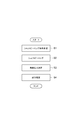
- FIG. 1 is a flowchart showing a yield strength estimation method according to the embodiment.
- the yield strength estimation method according to the embodiment is a method of estimating the yield strength of an object made of a metal material.
- the metallic material forming the object is, for example, a steel material.
- As the steel material specifically, a medium carbon quenched material having a carbon content of 0.5% to 0.6%, a high carbon carburizing material having a carbon content of 0.8% to 1.1%. Materials and the like.
- the medium carbon hardened material is used, for example, as a spring material or a die material for aluminum die-gust.
- High carbon carburizing materials are used, for example, in gear materials. All of these steel materials are martensitic steels having a martensitic structure.
- This yield strength estimation method estimates a yield strength by a step S1 (decision step) of determining shot peening conditions, a step S2 (shot peening step) of performing shot peening, a step S3 (measurement step) of measuring residual stress.
- the process S4 (estimation process) is included. Hereinafter, each step will be described.
- step S1 the shot peening conditions for giving the maximum residual stress to the object are determined.
- the maximum residual stress is the maximum value of the residual stress (compressive residual stress) that can be applied to the object.
- the maximum residual stress depends on the object.
- the residual stress applied to the object can be increased.
- increasing the hardness of the shot material may rather reduce the residual stress applied to the object. That is, in order to give the maximum residual stress to the object, it is necessary to optimize the balance between the hardness of the object and the hardness of the shot material.
- the hardness of the shot material higher than the hardness of the object within the range of 50 HV (Vickers hardness) or more and 250 HV or less.
- 50 HV Vanickers hardness
- 250 HV the projection energy is used for eroding the surface of the object, so that the residual stress cannot be effectively and stably applied to the surface part of the object.
- the amount of erosion increases, the amount of change in the size of the object also increases.
- the erosion amount of the target object By setting the erosion amount of the target object to 5 ⁇ m or less, residual stress can be effectively and stably applied to the surface portion of the target object, and the dimensional change of the target object can be suppressed.
- the hardness of the object means, for example, the hardness of the surface portion from the surface of the object to a depth of 0.050 mm.
- the shot peening condition determined in step S1 may be a condition other than the hardness of the shot material as long as it is a condition for giving the maximum residual stress.
- the particle size of the shot material can be 0.05 mm or more and 0.6 mm or less.
- the shot material can be easily manufactured.
- the position where the residual stress shows the maximum value in the depth direction (peak position) does not become too deep, and the peak position is within 100 ⁇ m from the surface of the object. It can fit. By keeping the peak position within this range, the fatigue strength of the object can be effectively improved.
- step S2 shot peening is performed on the object under the shot peening conditions determined in step S1. As a result, residual stress is applied to the surface portion of the object.
- step S3 the residual stress of the object after the shot peening in step S2 is measured.
- measurement is performed by, for example, a diffraction method.
- the diffraction method include an X-ray diffraction method, an electron beam diffraction method, and a neutron diffraction method.
- the measuring method by the X-ray diffraction method is disclosed in, for example, JP-A-2017-0093356.
- the measurement may be performed by the positron annihilation method.
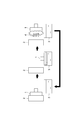
- FIG. 2 is a diagram for explaining the thermal fatigue test.
- thermal fatigue test thermal fatigue of the die-gust mold is reproduced.
- the test piece 1 is first pressed against the surface of the heater 2.
- the time for pressing the test piece 1 is set to 150 seconds.
- the temperature of the heater 2 is set so that the surface temperature of the test piece 1 becomes 570 ° C.
- the test piece 1 is cooled with water 3 at room temperature.
- the test piece 1 is dried by air blow in which air 4 is blown.
- the above-mentioned series of cycles is repeated for about 3 minutes.
- test piece 1 The material of the test piece 1 was SKD61 (JIS standard) which is hot tool steel. JIS standard SKD61 corresponds to ISO standard (ISO 4957: 1999) X40CrMoV5-1. Table 1 shows the chemical composition (wt%) of the test piece 1. Test piece 1 was prepared by quenching and tempering and then performing salt bath nitrocarburizing. The shape of the test piece 1 was a disk shape having a thickness of 15 mm and a diameter of 58 mm ( ⁇ 58), and a column having a height of 15 mm and a diameter of 15 mm ( ⁇ 15) was provided as a grip portion.
- JIS standard SKD61 corresponds to ISO standard (ISO 4957: 1999) X40CrMoV5-1. Table 1 shows the chemical composition (wt%) of the test piece 1. Test piece 1 was prepared by quenching and tempering and then performing salt bath nitrocarburizing. The shape of the test piece 1 was a disk shape having a thickness of 15 mm and a
- FIG. 3 is a graph showing changes in residual stress due to a cycle test.
- the horizontal axis of the graph is the number of cycles of the above-mentioned thermal fatigue test, and the vertical axis is the residual stress (MPa) of the test piece 1 (see FIG. 2).
- the cycle test is a thermal fatigue test with an extremely low cycle of up to 10 cycles, and was performed after shot peening was performed on the test piece 1 under the condition for giving the maximum residual stress.
- the residual stress was measured before the start of the cycle test, after the end of 5 cycles, and at the end of 10 cycles.
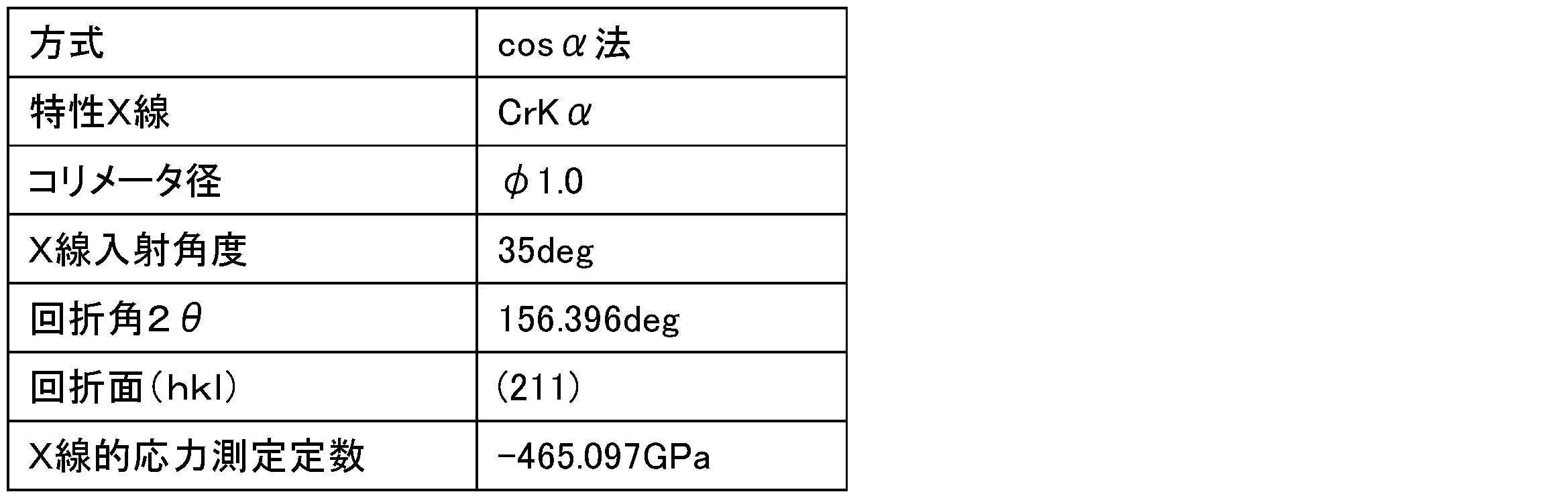
- the residual stress was measured by the X-ray diffraction method under the measurement conditions shown in Table 2. As shown in FIG. 3, as the number of cycles increased, the residual stress decreased due to thermal fatigue.
- step S4 the yield strength of the object is estimated based on the residual stress measured in step S3.
- step S4 the 0.2% proof stress of the object is estimated.
- Non-Patent Document 1 discloses that the maximum residual stress after shot peening is about 60% of 0.2% proof stress.
- Non-Patent Document 2 shows that the residual stress after shot peening is about half of the proof stress (yield stress).
- step S4 the 0.2% proof stress of the target object is estimated based on the residual stress of the target object after shot peening using these relationships. That is, in step S4, the proof stress of the object is estimated based on the residual stress measured in step S3 and the relationship between the maximum residual stress acquired in advance and the proof stress of the object.
- the proof stress estimation method after performing shot peening on the object under the shot peening conditions for imparting the maximum residual stress, the residual stress is measured, and the maximum residual stress of the object is calculated. Utilizing the relationship with the proof stress of the object, the proof stress of the object is estimated from the measured residual stress. Therefore, even if a destructive test such as a tensile test cannot be performed, the yield strength of the metal material forming the object can be easily estimated in a non-destructive manner.
- step S1 the shot peening conditions are determined based on the hardness of the target object, so the shot peening conditions can be appropriately determined.
- the measuring step S3 since the residual stress is measured by the diffraction method, the residual stress can be measured appropriately.
- the estimating step S4 the 0.2% proof stress of the object is estimated. Since 0.2% proof stress is widely used, there is a strong need for a proof stress estimation method.
- the object is made of steel material. Since steel materials are widely used, there is a strong need for a yield strength estimation method.
- test piece 1 ... test piece, 2 ... heater, 3 ... water, 4 ... air.
Landscapes
- General Physics & Mathematics (AREA)
- Health & Medical Sciences (AREA)
- Physics & Mathematics (AREA)
- Chemical & Material Sciences (AREA)
- Immunology (AREA)
- Biochemistry (AREA)
- General Health & Medical Sciences (AREA)
- Analytical Chemistry (AREA)
- Life Sciences & Earth Sciences (AREA)
- Pathology (AREA)
- Engineering & Computer Science (AREA)
- Mechanical Engineering (AREA)
- Toxicology (AREA)
- Crystallography & Structural Chemistry (AREA)
- Investigating Strength Of Materials By Application Of Mechanical Stress (AREA)
- Analysing Materials By The Use Of Radiation (AREA)
Abstract
耐力推定方法は、金属材料からなる対象物に最大残留応力を付与するためのショットピーニング条件を決定する決定工程と、対象物に対し、ショットピーニング条件でショットピーニングを行うショットピーニング工程と、ショットピーニング工程後の対象物の残留応力を測定する測定工程と、予め取得された最大残留応力と対象物の耐力との関係、及び、測定された残留応力に基づき対象物の耐力を推定する推定工程と、を含む。
Description
本開示は、耐力推定方法に関する。
金属材料からなる対象物の表面に高硬度の投射材(ショット)を投射するショットピーニングが知られている(例えば、非特許文献1,2)。ショットピーニングによれば、金属材料の疲労強度を向上させることができる。
小林祐次,"ショットピーニング特性に及ぼす機械的性質と残留オーステナイトの影響",ばね論文集,第57号,P.9-15,2012
岡田秀樹,"ショットピーニング方法の違いによる材料硬さと残留応力分布と降伏応力の関係",圧力技術第41号第5号,P.223-242,2003
ところで、金属材料の耐力は、引張試験によって求められる。しかしながら、実際の製品では、引張試験のような破壊試験を行うことができない場合がある。そのため、金属材料の耐力を非破壊で推定できる方法が必要とされている。
本開示は、金属材料の耐力を非破壊で推定できる耐力推定方法を提供する。
本開示に係る耐力推定方法は、金属材料からなる対象物に最大残留応力を付与するためのショットピーニング条件を決定する決定工程と、対象物に対し、ショットピーニング条件でショットピーニングを行うショットピーニング工程と、ショットピーニング工程後の対象物の残留応力を測定する測定工程と、予め取得された最大残留応力と対象物の耐力との関係、及び、測定された残留応力に基づき対象物の耐力を推定する推定工程と、を含む。
この耐力推定方法では、最大残留応力を付与するためのショットピーニング条件で対象物にショットピーニングが行われた後、残留応力が測定される。測定された残留応力から、対象物の最大残留応力と対象物の耐力との間に関係があることを利用して、対象物の耐力が推定される。したがって、引張試験を行うことができない場合であっても、対象物を構成する金属材料の耐力を非破壊で推定できる。
一実施形態に係る耐力推定方法において、決定工程では、対象物の硬さに基づいて、ショットピーニング条件を決定してもよい。この場合、ショットピーニング条件を適切に決定することができる。
一実施形態に係る耐力推定方法において、測定工程では、回折法により測定を行ってもよい。この場合、残留応力を適切に測定することができる。
一実施形態に係る耐力推定方法において、推定工程では、対象物の0.2%耐力を推定してもよい。この場合、0.2%耐力は広く用いられているので、耐力推定方法の必要性が高い。
一実施形態に係る耐力推定方法では、対象物は、鉄鋼材料からなってもよい。この場合、鉄鋼材料は広く用いられているので、耐力推定方法の必要性が高い。
本開示に係る耐力推定方法によれば、金属材料の耐力を非破壊で推定できる。
以下、添付図面を参照して、実施形態について詳細に説明する。説明において、同一要素又は同一機能を有する要素には同一符号を用い、重複する説明を省略する。
図1は、実施形態に係る耐力推定方法を示すフローチャートである。実施形態に係る耐力推定方法は、金属材料からなる対象物の耐力を推定する方法である。対象物を構成する金属材料は、例えば鉄鋼材料である。鉄鋼材料として、具体的には、炭素含有量が0.5%~0.6%である中炭素の焼入材、炭素含有量が0.8%~1.1%である高炭素の浸炭材等が挙げられる。中炭素の焼入材は、例えば、ばね材、アルミダイガスト用の金型材に用いられる。高炭素の浸炭材は、例えば、歯車材に用いられる。これらの鉄鋼材料は、いずれもマルテンサイト組織を有するマルテンサイト鋼である。
この耐力推定方法は、ショットピーニング条件を決定する工程S1(決定工程)と、ショットピーニングを行う工程S2(ショットピーニング工程)と、残留応力を測定する工程S3(測定工程)と、耐力を推定する工程S4(推定工程)と、を含む。以下、各工程について説明する。
工程S1では、対象物に最大残留応力を付与するためのショットピーニング条件を決定する。最大残留応力とは、対象物に付与可能な残留応力(圧縮残留応力)の最大値である。最大残留応力は、対象物によって異なる。
ショットピーニングでは、投射材の硬さを高めることにより、対象物に付与される残留応力を高めることができる。しかしながら、対象物の硬さが投射材の硬さに見合っていないと、投射材の硬さを高めることにより、対象物に付与される残留応力がかえって低下する場合がある。つまり、対象物に最大残留応力を付与するには、対象物の硬さと投射材の硬さとのバランスを適正化する必要がある。
対象物に最大残留応力を付与するには、例えば、投射材の硬さを対象物の硬さよりも50HV(ビッカース硬さ)以上250HV以下の範囲内で高く設定する。50HV以上とすることで、対象物の表面部分に残留応力を付与することができる。250HVよりも高く設定すると、投射のエネルギーが対象物の表面の削食に使われるので、対象物の表面部分に効果的かつ安定的に残留応力を付与することができない。削食量が大きくなると、対象物の寸法の変化量も大きくなる。対象物の削食量を5μm以下とすることで、対象物の表面部分に効果的かつ安定的に残留応力を付与することができるとともに、対象物の寸法の変化を抑制することができる。
ただし、対象物の硬さが750HVよりも低いと、対象物の表面部分に十分な残留応力を付与することができない場合がある。対象物の硬さは、例えば、対象物の表面から深さ0.050mmまでの表面部分の硬さを意味する。工程S1で決定されるショットピーニング条件は、最大残留応力を付与するための条件であれば、投射材の硬さ以外の条件であってもよい。
投射材の粒径は、0.05mm以上0.6mm以下とすることができる。投射材の粒径を0.05mm以上とすることにより、投射材を容易に作製することができる。投射材の粒径を0.6mm以下とすることにより、残留応力が深さ方向において最大値を示す位置(ピーク位置)が深くなりすぎず、ピーク位置を対象物の表面から深さ100μm以内に収めることができる。ピーク位置をこの範囲に収めることで、対象物の疲労強度を効果的に向上させることができる。
工程S2では、対象物に対し、工程S1で決定したショットピーニング条件でショットピーニングを行う。これにより、対象物の表面部分に残留応力が付与される。
工程S3では、工程S2のショットピーニング後の対象物の残留応力を測定する。工程S3では、例えば、回折法により測定を行う。回折法としては、具体的には、X線回折法、電子線回折法、及び中性子回折法等が挙げられる。X線回折法による測定方法は、例えば、特開2017-009356号公報に開示されている。工程S3では、陽電子消滅法により測定を行ってもよい。
ショットピーニングにより対象物に付与された残留応力は、熱疲労により減少する。例えば、ダイガスト金型では、溶湯により加熱されることで生じる熱応力と、離型剤により冷却されることで生じる熱応力とを繰り返し受けることによって、熱疲労が生じる。図2は、熱疲労試験について説明するための図である。この熱疲労試験では、ダイガスト金型の熱疲労が再現されている。図2に示されるように、この熱疲労試験では、まず試験片1がヒータ2の表面に押し付けられる。試験片1が押し付けられる時間は、150秒間に設定されている。ヒータ2の温度は、試験片1の表面温度が570℃となるように設定されている。その後、試験片1が室温の水3で冷却される。続いて、試験片1は、空気4を吹き付けるエアブローにより乾燥される。以上の一連のサイクルは約3分間で繰り返し行われる。
試験片1の材質は、熱間工具鋼であるSKD61(JIS規格)とした。JIS規格のSKD61は、ISO規格(ISO 4957:1999)のX40CrMoV5-1に対応している。試験片1の化学成分(wt%)を表1に示す。試験片1は、焼入焼戻しを行った後、塩浴軟窒化を行うことにより作成した。試験片1の形状は、厚さ15mm、直径58mm(φ58)の円盤形状とし、これに把持部として高さ15mm、直径15mm(φ15)の円柱を設けた。

図3は、サイクル試験による残留応力の変化を示すグラフである。グラフの横軸は、上述の熱疲労試験のサイクル数であり、縦軸は試験片1(図2参照)の残留応力(MPa)である。サイクル試験は、10サイクルまでの極低サイクルの熱疲労試験であり、試験片1に対して、最大残留応力を与えるための条件でショットピーニングを行った後に実施した。サイクル試験の開始前、5サイクル終了後、及び10サイクル終了時にそれぞれ残留応力を測定した。残留応力の測定は、X線回折法により、表2に示す測定条件で行った。図3に示されるように、サイクル数が増えるにしたがって、熱疲労により残留応力が減少した。
以上のことから、ショットピーニングにより付与された残留応力の測定は、ショットピーニング後の対象物に対し、残留応力を減少させる要因となる熱疲労を与える前に行われる必要がある。これにより、ショットピーニングにより付与された残留応力の測定精度を向上させることができる。
工程S4では、工程S3で測定した残留応力に基づき、対象物の耐力を推定する。工程S4では、対象物の0.2%耐力を推定する。非特許文献1には、ショットピーニング後の最大残留応力は、0.2%耐力の約60%程度であることが示されている。非特許文献2には、ショットピーニング後の残留応力は、耐力(降伏応力)の約半分であることが示されている。工程S4では、これらの関係を利用して、ショットピーニング後の対象物の残留応力に基づき対象物の0.2%耐力を推定する。すなわち、工程S4では、工程S3で測定した残留応力、及び、予め取得された最大残留応力と対象物の耐力との関係に基づき、対象物の耐力を推定する。
以上説明したように、実施形態に係る耐力推定方法では、最大残留応力を付与するためのショットピーニング条件で対象物にショットピーニングを行った後、残留応力を測定し、対象物の最大残留応力と対象物の耐力との間に関係があることを利用して、測定された残留応力から、対象物の耐力を推定する。したがって、引張試験のような破壊試験を行うことができない場合であっても、対象物を構成する金属材料の耐力を非破壊で簡便に推定できる。
工程S1では、対象物の硬さに基づいて、ショットピーニング条件を決定するので、ショットピーニング条件を適切に決定することができる。測定する工程S3では、回折法により残留応力を測定するので、残留応力を適切に測定することができる。推定する工程S4では、対象物の0.2%耐力を推定する。0.2%耐力は広く用いられているので、耐力推定方法の必要性が高い。対象物は、鉄鋼材料からなる。鉄鋼材料は広く用いられているので、耐力推定方法の必要性が高い。
本発明は必ずしも上述した実施形態に限定されるものではなく、その要旨を逸脱しない範囲で様々な変更が可能である。
1…試験片、2…ヒータ、3…水、4…空気。
Claims (5)
- 金属材料からなる対象物に最大残留応力を付与するためのショットピーニング条件を決定する決定工程と、
前記対象物に対し、前記ショットピーニング条件でショットピーニングを行うショットピーニング工程と、
前記ショットピーニング工程後の前記対象物の残留応力を測定する測定工程と、
予め取得された前記最大残留応力と前記対象物の耐力との関係、及び、測定された前記残留応力に基づき前記対象物の耐力を推定する推定工程と、を含む、耐力推定方法。 - 前記決定工程では、前記対象物の硬さに基づいて、ショットピーニング条件を決定する、請求項1に記載の耐力推定方法。
- 前記測定工程では、回折法により測定を行う、請求項1又は2に記載の耐力推定方法。
- 前記推定工程では、前記対象物の0.2%耐力を推定する、請求項1~3のいずれか一項に記載の耐力推定方法。
- 前記対象物は、鉄鋼材料からなる、請求項1~4のいずれか一項に記載の耐力推定方法。
Applications Claiming Priority (2)
| Application Number | Priority Date | Filing Date | Title |
|---|---|---|---|
| JP2018-209559 | 2018-11-07 | ||
| JP2018209559A JP6838596B2 (ja) | 2018-11-07 | 2018-11-07 | 耐力推定方法 |
Publications (1)
| Publication Number | Publication Date |
|---|---|
| WO2020095486A1 true WO2020095486A1 (ja) | 2020-05-14 |
Family
ID=70612235
Family Applications (1)
| Application Number | Title | Priority Date | Filing Date |
|---|---|---|---|
| PCT/JP2019/029540 Ceased WO2020095486A1 (ja) | 2018-11-07 | 2019-07-26 | 耐力推定方法 |
Country Status (2)
| Country | Link |
|---|---|
| JP (1) | JP6838596B2 (ja) |
| WO (1) | WO2020095486A1 (ja) |
Citations (1)
| Publication number | Priority date | Publication date | Assignee | Title |
|---|---|---|---|---|
| US7159425B2 (en) * | 2003-03-14 | 2007-01-09 | Prevey Paul S | Method and apparatus for providing a layer of compressive residual stress in the surface of a part |
-
2018
- 2018-11-07 JP JP2018209559A patent/JP6838596B2/ja active Active
-
2019
- 2019-07-26 WO PCT/JP2019/029540 patent/WO2020095486A1/ja not_active Ceased
Patent Citations (1)
| Publication number | Priority date | Publication date | Assignee | Title |
|---|---|---|---|---|
| US7159425B2 (en) * | 2003-03-14 | 2007-01-09 | Prevey Paul S | Method and apparatus for providing a layer of compressive residual stress in the surface of a part |
Non-Patent Citations (2)
| Title |
|---|
| KOBAYASHI, YUJI ET AL.: "Influences of mechanical properties and retained austenite content on shot-peening characteristics", TRANSACTIONS OF JAPAN SOCIETY FOR SPRING RESEARCH, vol. 2012, no. 57, 30 May 2012 (2012-05-30), pages 9 - 15 * |
| OKADA, HIDEKI ET AL.: "Relationship among specimen's hardness, residual stress distribution and yield stress on the difference of shot peening methods", JOURNAL OF HIGH PRESSURE INSTITUTE OF JAPAN, vol. 41, no. 5, 11 November 2003 (2003-11-11), pages 233 - 242 * |
Also Published As
| Publication number | Publication date |
|---|---|
| JP6838596B2 (ja) | 2021-03-03 |
| JP2020076622A (ja) | 2020-05-21 |
Similar Documents
| Publication | Publication Date | Title |
|---|---|---|
| Benedetti et al. | Notch fatigue behaviour of shot peened high-strength aluminium alloys: Experiments and predictions using a critical distance method | |
| Gao | Improvement of fatigue property in 7050–T7451 aluminum alloy by laser peening and shot peening | |
| JP4775525B2 (ja) | 鋼材製品のショットピーニング処理法 | |
| Kamaya et al. | True stress–strain curve acquisition for irradiated stainless steel including the range exceeding necking strain | |
| Nordin et al. | Experimental investigation of shot peening on case hardened SS2506 gear steel | |
| Slima | Ion and gas nitriding applied to steel tool for hot work X38CrMoV5 nitriding type: impact on the wear resistance | |
| KR101482619B1 (ko) | 쇼트 피닝용 투사재의 제조방법 | |
| Petan et al. | Effects of Laser Shock Peening on the Surface Integrity of 18% Ni Maraging Steel. | |
| JP6881420B2 (ja) | 劣化評価方法 | |
| JP6838596B2 (ja) | 耐力推定方法 | |
| CN103774085A (zh) | 一种在低碳合金钢表面制备的高氮奥氏体层及制备方法 | |
| JP2002060845A (ja) | ダイカスト金型の高寿命化方法 | |
| Nikhare et al. | Investigation of acoustic signals during W1 tool steel quenching | |
| JP6416735B2 (ja) | 窒化部品の製造方法及び窒化部品 | |
| Lübben | Basics of distortion and stress generation during heat treatment | |
| Nakonieczny et al. | Contact fatigue strength of 41CrAlMo7 grade steel under nitriding and shot-peening treatment | |
| Filep et al. | Residual stress distribution caused by laser hardening and conventional quenching in plain carbon steel | |
| Hatos et al. | Study of 2d and 3d methods for worn surface analysis of tool materials | |
| Neimitz et al. | Master curve of high-strength ferritic steel S960-QC | |
| Easton et al. | Effects of Forming Route and Heat Treatment on the Distortion Behavior of Case-Hardened Martensitic Steel type S156 | |
| JP2017090083A (ja) | 放射線厚み測定装置及びその校正方法 | |
| Žagar et al. | Surface modification analysis after shot peening of AA 7075 in different states | |
| Powar | Effect of Different Hardening Processes on Brass, Aluminium and Mild Steel on Impact Number | |
| Janutienė | Investigation of hardening and tempering deformations of carburized low alloy steel | |
| Chadwick | Mechanism of shot peening enhancement for the fatigue performance of AA7050-T7451 |
Legal Events
| Date | Code | Title | Description |
|---|---|---|---|
| 121 | Ep: the epo has been informed by wipo that ep was designated in this application |
Ref document number: 19882287 Country of ref document: EP Kind code of ref document: A1 |
|
| NENP | Non-entry into the national phase |
Ref country code: DE |
|
| 122 | Ep: pct application non-entry in european phase |
Ref document number: 19882287 Country of ref document: EP Kind code of ref document: A1 |