WO2020090878A1 - Medical fluid container assembly clamper, medical fluid injection device having clamper, and medical fluid injection system - Google Patents
Medical fluid container assembly clamper, medical fluid injection device having clamper, and medical fluid injection system Download PDFInfo
- Publication number
- WO2020090878A1 WO2020090878A1 PCT/JP2019/042547 JP2019042547W WO2020090878A1 WO 2020090878 A1 WO2020090878 A1 WO 2020090878A1 JP 2019042547 W JP2019042547 W JP 2019042547W WO 2020090878 A1 WO2020090878 A1 WO 2020090878A1
- Authority
- WO
- WIPO (PCT)
- Prior art keywords
- holding structure
- syringe
- clamper
- drug solution
- syringe assembly
- Prior art date
Links
Images


Classifications
-
- A—HUMAN NECESSITIES
- A61—MEDICAL OR VETERINARY SCIENCE; HYGIENE
- A61M—DEVICES FOR INTRODUCING MEDIA INTO, OR ONTO, THE BODY; DEVICES FOR TRANSDUCING BODY MEDIA OR FOR TAKING MEDIA FROM THE BODY; DEVICES FOR PRODUCING OR ENDING SLEEP OR STUPOR
- A61M5/00—Devices for bringing media into the body in a subcutaneous, intra-vascular or intramuscular way; Accessories therefor, e.g. filling or cleaning devices, arm-rests
- A61M5/14—Infusion devices, e.g. infusing by gravity; Blood infusion; Accessories therefor
- A61M5/142—Pressure infusion, e.g. using pumps
- A61M5/145—Pressure infusion, e.g. using pumps using pressurised reservoirs, e.g. pressurised by means of pistons
Definitions
- the present invention relates to a clamper for holding a drug solution container assembly when injecting a drug solution using a drug solution injector, and various devices having the clamper.
- Medical diagnostic imaging devices include CT (Computed Tomography) scanners, MRI (Magnetic Resonance Imaging) devices, PET (Positron Emission Tomography) devices, angio devices, and MRA (MR Angio) devices.
- CT Computer Tomography
- MRI Magnetic Resonance Imaging
- PET PET
- angio angio
- MRA MR Angio
- the liquid medicine injection device has an injection head to which a liquid medicine container such as a syringe or a liquid medicine bag filled with the liquid medicine is detachably mounted, and an injection control unit for controlling the operation of the liquid injection head.
- the injection head includes a clamper for fixing the drug solution container to the injection head, and a drive mechanism for discharging the drug solution from the drug solution container to the outside with the drug solution container fixed to the injection head.
- the chemical liquid container may be misaligned or removed from the chemical liquid injection device during the injection of the chemical liquid. It is important that the drug solution container be held by the drug solution injector so that the drug solution will not be damaged.
- Patent Document 1 International Publication No. 2011/099551 discloses a drug solution injector having a syringe mounting part on which a syringe assembly is mounted and a clamper holding the syringe assembly mounted on the syringe mounting part. ing.
- the clamper has a base member on which the flange of the syringe assembly is placed, a flange pressing member, and an engaging structure.
- the flange pressing member is rotatably supported by the base member between an open position and a closed position.
- the engagement structure locks the flange pressing member to the base member in the closed position.
- the flange of the syringe assembly is placed on the base member with the flange pressing member in the open position. Next, the flange pressing member is rotated to the closed position, and the flange pressing member is locked to the base member by the engagement structure. This holds the syringe assembly.
- Patent Document 1 International Publication No. 2011/099551
- the syringe assembly is held by closing the clamper after the syringe assembly is mounted on the syringe mounting portion. Therefore, if the syringe assembly is mounted on the syringe mounting portion, the operation of the chemical injection device may be possible even if the user forgets to close the clamper. If the chemical liquid injection operation, which is one of the operations of the chemical liquid injection device, is executed while the clamper is not closed, the syringe assembly may drop during the chemical liquid injection operation.
- This problem can be solved by using a sensor that detects whether the clamper is closed.
- this type of sensor is usually a sensor based on a change in electrical output value, and cannot detect that the clamper is closed when a malfunction such as a failure occurs in the sensor itself.
- One of the objects of the present invention is to provide a clamper and the like that can effectively mount the drug solution container assembly at a predetermined position and close the clamper.
- a clamper detachably holding a drug solution container assembly, comprising: A first holding structure having a first receiving portion for receiving a part of the chemical liquid container assembly in the outer peripheral direction; A second holding structure that has a second receiving portion that receives a part of the chemical liquid container assembly in the outer peripheral direction, and that holds the chemical liquid container assembly in cooperation with the first holding structure; Have The second holding structure is movable between an open position and a closed position with respect to the first holding structure, and the second receiving portion receives a part of the drug solution container assembly in the open position.
- a clamper is provided that is supported so that
- a clamper of the present invention A drive mechanism for discharging the drug solution contained in the drug solution container assembly held by the clamper from the drug solution container assembly,
- a liquid medicine injection device having:
- a liquid injector according to the present invention, A drug solution container assembly for containing a drug solution; A system is provided having.
- the “axial direction” of the drug solution container assembly or the syringe assembly refers to the longitudinal direction of the drug solution container assembly or the syringe assembly.
- a typical drug solution container assembly or syringe assembly has an opening for discharging a drug solution at one axial end thereof.
- the “radial direction” of the drug solution container assembly or the syringe assembly refers to a direction perpendicular to the “axial direction”.
- the present invention it is possible to mount the drug solution container assembly at a predetermined position by utilizing the movement of the drug solution container assembly associated with the closing operation of the clamper.
- FIG. 1 is a schematic block diagram of a medical image capturing system according to an embodiment of the present invention. It is a perspective view which shows an example of the external appearance of the injection head which can be equipped with the chemical injection device shown in FIG. It is a perspective view of the syringe mounting part of the injection head shown in FIG. It is a figure explaining one form of arrangement of the 1st holding structure and the 2nd holding structure. It is a figure explaining the other form of arrangement
- FIG. 7B is a view showing the state where the syringe assembly is received in the second holding structure in FIG. 7A.
- FIG. 7B is a view showing the state where the syringe assembly is received by the second holding structure in the open position in the injection head shown in FIG. 7A.
- FIG. 7B is a view showing one form of a syringe release mechanism applicable to a clamper of the present invention.
- FIG. 7A is a principal part perspective view of a clamper which shows the example of arrangement
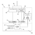
- FIG. 1 there is shown a block diagram of a medical image capturing system according to an embodiment of the present invention, which includes a liquid medicine injection device 100 and a medical image capturing device 500. Further, the liquid medicine injection device 100 and the medical image capturing device 500 can be connected to each other so that data can be transmitted and received between them.
- the connection between the two may be a wired connection or a wireless connection.
- the medical image capturing apparatus 500 includes an image capturing operation unit 520 that executes an image capturing operation, and an image capturing control unit 510 that controls the operation of the image capturing operation unit 520, and a subject to which the liquid medicine is injected by the liquid medicine injector 100. Medical images including tomographic images and / or three-dimensional images can be acquired.
- the imaging operation unit 520 generally includes a bed for a subject, an electromagnetic wave irradiation unit that irradiates a predetermined space on the bed with electromagnetic waves, and the like.
- the image capturing control unit 510 controls the operation of the entire medical image capturing apparatus, such as determining the image capturing condition and controlling the operation of the image capturing operation unit 520 according to the determined image capturing condition.
- the imaging control unit 510 can be configured by including a so-called microcomputer, and can have a CPU, a ROM, a RAM, and an interface with other devices.
- a computer program for controlling the medical image capturing apparatus 500 is installed in the ROM.
- the CPU controls the operation of each unit of the medical image capturing apparatus 500 by executing various functions corresponding to this computer program.
- the medical image capturing apparatus 500 may further include a display unit 504 such as a liquid crystal display capable of displaying an image capturing condition and an acquired medical image, and an input unit 503 such as a keyboard and / or a mouse for receiving an input of the image capturing condition. it can. At least part of the data used to determine the imaging condition is input from the input unit 503 and transmitted to the imaging control unit 510. The data displayed on the display unit 504 is transmitted from the imaging control unit 510.
- a touch panel in which a touch screen is arranged as an input unit on the display of the display unit can also be used as the input unit 503 and the display unit 504.
- a part of the input unit 503, the display unit 504, and the imaging control unit 510 can be incorporated into one housing as a console for the medical image imaging apparatus.
- the drug solution injector 100 is a device used to inject a drug solution filled in a syringe assembly 200, which is a drug solution container assembly, into a blood vessel of a subject through an injection circuit 300, and at least one piston drive mechanism 130. And at least one input unit 103, at least one display unit 104, and an injection control unit 101.
- the piston drive mechanism 130 is a mechanism that operates a piston of a syringe, and in the present embodiment, the drug solution injector 100 is configured so that two kinds of drug solutions (for example, a contrast agent and a physiological saline solution) can be separately or simultaneously injected.
- one syringe assembly 200 can be mounted, and has two piston drive mechanisms 130 for independently operating the respective pistons of these two syringe assemblies 200.
- the number of piston drive mechanisms 130 may be one, or may be three or more, depending on the number of syringe assemblies 200 mounted on the chemical liquid injector 100.
- the injection control unit 101 uses at least a part of the data input from the input unit 103 to determine the injection conditions such as the injection amount and the injection speed of the drug solution, and to inject the drug solution from the syringe according to the determined injection conditions.
- the operation of the liquid injector is controlled by controlling the operation of the piston drive mechanism 130 and the display of the display unit 104.
- the injection control unit 101 can be configured to include a so-called microcomputer, and can have a CPU, a ROM, a RAM, and an interface with other devices.
- a computer program for controlling the chemical liquid injector 100 is installed in the ROM.
- the CPU can control the operation of each unit of the chemical injection device 100 by executing various functions in accordance with this computer program.
- the input unit 103 is a unit that accepts inputs such as data used by the injection control unit 101 to determine the injection conditions of the drug solution.
- the input unit 103 may be a known input device such as a keyboard and / or a mouse.
- the data input from the input unit 103 is transmitted to the injection control unit 101, and the data displayed on the display unit 104 is transmitted from the injection control unit 101.
- the display unit 104 is controlled by the injection control unit 101, and displays data necessary for determining the injection conditions of the drug solution, the injection protocol, the injection operation, and various warnings.
- the injection protocol indicates what kind of liquid medicine is injected, how much it is, and at what speed.
- the injection rate may be constant or may change with time.
- the injection protocol also includes information on the order in which the drug solutions are injected.
- any known injection protocol can be used.
- a known procedure can be used as the procedure for creating the injection protocol.
- the injection protocol may also include the maximum allowable injection pressure (pressure limit). When the pressure limit is set, the injection pressure is monitored during the injection operation, and the operation of the piston drive mechanism 130 is controlled so that the injection pressure does not exceed the set pressure limit.
- the display unit 104 may be a known display device such as a liquid crystal display device.
- a touch panel in which a touch screen is arranged as an input unit on the display of the display unit can also be used as the input unit 103 and the display unit 104.
- the chemical injection device 100 can have an injection head 100a and a console 100b as a housing.
- the injection head 100a can have a piston drive mechanism 130, and the syringe assembly 200 is removably mounted.
- the console 100b can have an injection control unit 101, an input unit 103, and a display unit 104.
- the input unit 103 and / or the display unit 104 different from the input unit 103 and the display unit 104 included in the injection control unit 101 may be provided in the injection head 100a, or the injection head 100a and the console 100b. It may be provided separately.
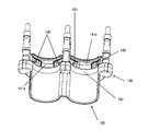
- the injection head 100a is configured so that two syringe assemblies 200 can be detachably mounted in parallel with each other as a drug solution container assembly (in FIG. 2, one syringe is shown for simplification). Only assembly 200 is shown).
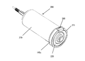
- the syringe assembly 200 has a syringe 220 and a protective cover 270 into which the syringe 220 is inserted.
- the syringe 220 is a syringe 220 generally called a rodless syringe, and has a cylinder 221 and a piston 222 inserted into the cylinder 221 so as to be movable back and forth.
- a cylinder flange 221a and a nozzle portion 221b are formed at the end and the tip of the cylinder 221, respectively.
- a convex portion (not shown) held by the piston drive mechanism 130 is integrally formed at the end of the piston 222.
- the syringe 220 may be a prefilled type syringe provided with a drug solution in a state filled with a drug solution, or a field-filled type syringe filled with a drug solution at a medical site.
- the drug solution filled in the syringe 220 is pushed out of the syringe 220 via the nozzle portion 221b.
- An extension tube (not shown) having an injection needle or catheter connected to its tip is connected to the nozzle portion 221b, and the injection needle or catheter is punctured or inserted into the blood vessel of the subject to inject the drug solution in the syringe 220 into the subject.
- the liquid medicine filled in the syringe 220 include a contrast agent and physiological saline.
- the syringe 220 may be filled with a therapeutic drug solution such as an anti-cancer agent instead of the contrast agent and may be administered to the subject.
- a drug solution injected using the drug solution injector 100 often has a high viscosity like a contrast agent. Further, in particular, when a blood vessel image of a subject is taken using the angio apparatus, a contrast agent is injected through a thin catheter. As a result, the internal pressure of the cylinder 221 tends to be extremely high during the injection of the contrast agent. This high internal pressure causes the cylinder 221 to expand, which may cause various problems in the injection of the chemical liquid.
- the protective cover 270 has a cylindrical shape so that the cylinder 221 is inserted without a gap between the outer peripheral surface of the cylinder 221 and the inner peripheral surface of the protective cover 270 in order to suppress expansion due to an increase in internal pressure of the cylinder 221 during injection of the chemical liquid. It is a component that is configured in a shape. Since the protective cover 270 plays this role, the protective cover 270 is formed with a wall thickness having a mechanical strength sufficient to withstand the internal pressure acting on the cylinder 221 during the injection of the chemical liquid.
- An opening is formed at the tip of the protective cover 270, and the cylinder 221 is inserted into the protective cover 270 with the nozzle portion 221b protruding from this opening.
- a cover flange 271 having a ring-shaped recess for receiving the cylinder flange 221a of the cylinder 221 is formed.
- the injection head 100a has two piston drive mechanisms 130 (see FIG. 1) that are driven independently of each other for advancing and retracting the pistons 222 of the two syringe assemblies 200 attached, and each syringe assembly 200 is attached. It is arranged corresponding to the position.
- Each of the piston drive mechanisms 130 holds a presser 131 that holds the above-mentioned convex portion at the end of the piston 222, a drive source (not shown) such as a motor that advances and retracts the presser 131, and a power transmission mechanism that connects these. (Not shown).
- the syringe assembly 200 mounted on the injection head 100a can inject the drug solution filled in the syringe 220 into the subject by moving the piston 222 forward by the piston drive mechanism 130.
- the liquid medicines filled in the two syringes 200 are separately, sequentially or simultaneously controlled by appropriately controlling the operation of each piston drive mechanism 130. Can be injected into.
- the piston drive mechanism 130 a known mechanism generally used in this type of injection device can be adopted.
- the operation of each piston drive mechanism 130 is controlled by the injection control unit 101 according to the injection protocol when injecting the drug solution, but it is preferable that the piston drive mechanism 130 can be operated in any other manner.
- the input unit 103 may further include a button group 103a and / or a manual knob 103b in the injection head 100a, which includes a button for arbitrarily advancing the presser 131 and a button for arbitrarily retracting the presser 131.
- the injection control unit 101 controls the operation of each piston drive mechanism according to the pressing operation of each button of the button group 103a and the rotation operation of the manual knob 103b by the operator.
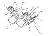
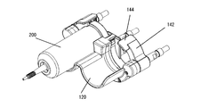
- the tip of the injection head 100a is provided with a syringe assembly receiver 120 and a clamper 140 that constitute a syringe mounting portion on which the syringe assembly 200 is mounted.
- the syringe assembly receiver 120 is located closer to the tip side than the clamper 140, and has two recesses 121 that can individually receive the outer peripheral surface of the protective cover 270.
- the syringe assembly 200 is injected by holding the cover flange 271 by the clamper 140 in a state where the syringe assembly receiver 120 is received by the syringe assembly receiver 120 with the nozzle portion 221b facing the front end side and is placed on the syringe placing portion. It is fixed to the head 100a.
- clamper 140 will be described in more detail with reference to FIG.
- the clamper 140 has a first holding structure 141 that cooperates to hold the syringe assembly 200 and at least one second holding structure 142.
- the first holding structure 141 and the second holding structure are configured to hold the syringe assembly 200 in a state where the syringe assembly 200 is placed on the syringe mounting portion.
- the clamper 140 has two second holding structures 142 so that the injection head 100a (see FIG. 2) can mount the two syringe assemblies 200.
- the number of the second holding structures 142 may be one, or may be three or more, corresponding to the number of the syringe assemblies 200 mounted on the injection head 100a.
- the configuration of the first holding structure 142 and the configuration of the syringe assembly receiver 120 are changed according to the number of syringe assemblies 200 that can be mounted. For example, if the number of syringe assemblies 200 that can be mounted is one, the first holding structure 141 has one flange receiving portion 141a (described later), and the syringe assembly receiver 120 has one recess 121.
- the clamper 140 may further include at least one support member that supports the first holding structure 141 and the second holding structure 142 with respect to the injection head 100a.
- the clamper 140 has, as a support member, a center shaft 150a and two clamper shafts 150b arranged in parallel with the center shaft 150a on both sides of the center shaft 150a.
- the first holding structure 141 is fixedly supported by the center shaft 150a and the two clamper shafts 150b with respect to the injection head 100a.
- the two second holding structures 142 are rotatably supported around the clamper shaft 150b by the left and right clamper shafts 150b.
- the first holding structure 141 has two flange receiving portions 141a (first receiving portions) located between the center shaft 150a and the clamper shaft 150b as a structure for receiving a part of the syringe assembly 200 in the outer peripheral direction.
- each flange receiving portion 141a can receive a part of the cover flange 271 along the outer peripheral direction so as to be substantially immovable in the axial direction of the syringe assembly 200 but movably in the radial direction. It is configured as a recess that can be formed.
- the first holding structure 141 can be configured by one member, or can be configured by combining a plurality of members.
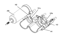
- the second holding structure 142 is movably supported between an open position and a closed position with respect to the first holding structure 141, can receive a part of the flange assembly 200 in the outer peripheral direction in the open position, and In the closed position, it is configured to cooperate with the first retaining structure 141 to retain the syringe assembly 200.
- the second holding structure 142 also has a flange receiving portion 142a (second receiving portion) as a structure for receiving a part of the syringe assembly 200 in the circumferential direction similarly to the first holding structure 141. have.
- the flange receiving portion 142a can receive a part of the cover flange 271 along the outer peripheral direction so as to be substantially immovable in the axial direction of the syringe assembly 200 but movably in the radial direction. It is configured as a recess.
- the flange receiving portion 142a is preferably provided with a non-slip member 142b for preventing the syringe assembly 200 from rotating. Any material may be used to form the anti-slip member 142b, and for example, a rubber material such as silicone rubber may be used. By forming the anti-slip member 142b from a rubber material, the anti-slip member 142b can also serve as a cushion.
- the second holding structure 142 can be formed of one member or a combination of a plurality of members.
- the flange receiving portion 141a of the first holding structure 141 and the flange receiving portion 142a of the second flange holding structure 142 are such that when the second holding structure 142 is in the closed position, both flange receiving portions 141a, 142a cooperate. Configured to operatively and immovably receive the cover flange 271 both axially and radially of the syringe assembly 200. This holds the syringe assembly 200.
- immovable as used in this specification includes not only that the target structure does not move at all, but also that the structure can move within a clearance that occurs due to design dimensional tolerances and the like.
- the total length of the length L1 and the length L2 is more than half the length of the entire circumference of the syringe assembly 200 in the circumferential direction.
- the length L1 is the circumferential length of the portion of the syringe assembly 200 that is received by the flange receiving portion of the first holding structure 141.
- the length L2 is the circumferential length of the portion of the syringe assembly 200 that is received by the flange receiving portion of the second holding structure 142.
- each of length L3 and length L4 may be less than half the length of the entire circumference of syringe assembly 200 in the circumferential direction.
- the lengths L3 and L4 are circumferential lengths of the portion of the syringe assembly 200 that is not received by either the flange receiving portion of the first holding structure 141 or the flange receiving portion of the second holding structure 142.
- the former configuration is adopted.
- the first holding structure 141 and the second holding structure 142 may be continuously arranged in the circumferential direction of the syringe assembly 200, or may be arranged separately.
- the shapes of the first holding structure 141 and the second holding structure are not particularly limited and may be arbitrary. However, at least each inner surface (the surface facing the syringe assembly when the syringe assembly is held) has a length along the outer peripheral direction of the syringe assembly 200 so that a part of the outer peripheral direction of the syringe assembly 200 can be received. It is preferable that the shape has In this embodiment, since the syringe assembly 200 has a cylindrical outer shape as a whole, the flange receiving portion 141a of the first holding structure 141 and the flange receiving portion 142a of the second holding structure 142 are substantially semi-circular. Is formed in.
- the movement path of the second holding structure 142 may be arbitrary as long as it can move between the open position and the closed position.
- the movement of the second holding structure 142 between the open position and the closed position may be rotation as in the present embodiment, linear movement, or a combination thereof. Good.
- the second holding structure 142 is movably supported between the open position and the closed position, any part of the second holding structure 142 may be supported, and one end thereof is supported. Alternatively, other parts may be supported.
- the second holding structure 142 is configured in a semi-circular shape as a whole corresponding to the outer shape of the syringe assembly 200, and the intermediate portion in the longitudinal direction of the semi-circular shape is attached to the clamper shaft 150b and the clamper shaft 150b.
- the second holding structure 142 is rotatably supported around which the part of the flange receiving part 141a is located in the flange receiving part 141a of the first holding structure 141 when in the closed position. Then, with the movement of the second holding structure 142 toward the open position, a part of the flange receiving portion 142a located in the flange receiving portion 141a is configured to be detached from the flange receiving portion 141a.
- the user When mounting the syringe assembly 200 on the injection head 100a, the user first moves the second holding structure 142 to the open position. In this state, the user places the syringe assembly 200 on the second holding structure 142 so that the cover flange 271 of the syringe assembly 200 is received by the flange receiving portion 142a of the second holding structure 142 (see FIGS. 5A and 5B). ).
- the flange receiving portions 141a, 142a of the first holding structure 141 and the second holding structure 142 are both formed in a semi-circular shape, and the second holding structure 142 has a long length. It is supported at the middle part of the direction (direction along the arc).
- the orientation of the open end of the flange receiving portion 142a of the second holding structure 142 is the same as the orientation of the open end of the flange receiving portion 141a of the first holding structure 141.
- the second holding structure 142 has a posture in which it is easy to receive the syringe assembly 200.
- the syringe is provided at any position that creates a space in which the syringe assembly 200 can be radially inserted between the first holding structure 141 and the second holding structure 142.
- the assembly 200 can be received.
- the open position can be any position that creates a space between the first retaining structure 141 and the second retaining structure 142 that allows the syringe assembly 200 to be radially inserted.
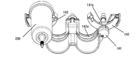
- the user moves the second holding structure 142, in which the syringe assembly 200 is received, to the closed position (FIGS. 6A and 6B).
- the syringe assembly 200 moves (rotates) with the second holding structure 142 and is received by the syringe assembly receiver 120, whereby the syringe assembly 200 is The syringe is mounted at a fixed position placed on the syringe mount.
- the cover flange 271 of the syringe assembly 200 is held by the first holding structure 141 and the second holding structure 142.
- an injection needle or a catheter is connected to the syringe assembly 200 via an extension tube to set the injection conditions of the drug solution and set the drug solution injector 100.
- the drug solution can be injected into the subject through a procedure similar to the conventional one such as operating.
- the syringe assembly 200 mounted on the injection head 100a can be removed from the injection head 100a in the reverse order of the mounting procedure described above.
- the syringe assembly 200 is placed on the second holding structure 142 when the second holding structure 142 is in the open position, and in that state the second holding structure 142 is moved to the closed position.
- This mounts the syringe assembly 200 in place. This allows the syringe assembly 200 to be mounted at a fixed position and held by the clamper 140 at the same time by an extremely intuitive operation of moving the second holding structure 142 on which the syringe assembly 200 is placed from the open position to the closed position. be able to.
- the clamper 140 can have a stop in the open position and / or a stop in the closed position of the second retaining structure 142.
- the clamper 140 having the stopper in the open position can stabilize the position of the second holding structure 142 in the open position and facilitate the reception of the syringe assembly 200 in the second holding structure 142. Since the clamper 140 has the stopper mechanism at the closed position, the second holding structure 142 can maintain the closed state of the clamper 140 at the closed position.
- any mechanism that can hold the second holding structure 142 in the open position and / or the closed position in a disengageable manner can be used.
- the stopper is a combination of a spring plunger attached to the second holding structure 142 and an engagement recess formed in a member that contacts the second holding structure 142 in the open position and / or the closed position. it can.
- the relationship between the spring plunger and the engagement recess may be reversed.
- the spring plunger has a main body, a movable body such as a ball or a pin held in the main body so as to be movable back and forth with respect to the main body, and a spring for urging the movable body from the inside of the main body.
- the spring plunger has a structure in which a part of the movable body projects from the main body by the biasing force of the spring when no load is applied, but the movable body sinks into the main body when a load is applied.
- the engagement recess is formed at a position facing the spring plunger when the second holding structure 142 is in the open position and / or the closed position.
- the clamper 140 may have a syringe lock structure that detachably locks the syringe assembly 200 received by the first holding structure 141.
- the syringe lock mechanism include a holding hook 143 (see FIG. 3 and the like) provided on the first holding structure 141.
- the holding hook 143 is provided in the flange receiving portion 141a of the first holding structure 141 at a position that engages with the outer peripheral surface of the cover flange 271 of the syringe assembly 200 received by the flange receiving portion 141a.
- the clamper 140 can also include both a syringe lock mechanism and a lock mechanism in the closed position of the second holding structure 142, which allows the syringe assembly 200 to be held more firmly.
- the second holding structure 142 can have an operating lever 144 for the user to move the second holding structure 142 between an open position and a closed position.
- the position of the operation lever 144 on the second holding structure 142 may be arbitrary, but by providing the operation lever 144 at the end portion away from the rotation center of the second holding structure 142, a smaller force is applied.
- the second holding structure 142 can be moved (rotated).
- the operation lever 144 of the second holding structure 142 which is the farthest from the syringe mounting portion (syringe assembly receiver 120) when the second holding structure 142 is in the closed position, is viewed from the axial direction of the syringe assembly 200. It is preferably located in a portion (see, eg, FIG. 6B).
- the clamper 140 may be configured such that the syringe assembly 200 received in the second holding structure 142 is adsorbed to the second holding structure 142.
- Magnetism can be used to attract the syringe assembly 200.
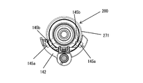
- FIG. 7A An example of an adsorption structure using magnetism is shown in FIG. 7A.
- the second holding structure 142 and the syringe assembly 200 have magnetic attraction members 145a and 145b, respectively.
- these magnetic attraction members 145a and 145b face each other when the syringe assembly 200 is received by the second holding structure 142, and one magnetic attraction member 145a and the other magnetic attraction member 145b. Are arranged in a pair.
- the magnetic attraction member 145b on the syringe assembly 200 side is arranged near or inside the outer peripheral surface of the cover flange 271, and the magnetic attraction member 145a on the second holding structure 142 side is arranged in the flange receiving portion 142a. There is.
- the syringe assembly 200 received in the second holding structure 142 is magnetically attracted by the magnetic attraction members 145a and 145b, so that the posture of the injection head 100a is, for example, the tip side of the injection head 100a (the syringe assembly receiving 120 side).
- the syringe assembly 200 can be reliably received by the second holding structure 142 without being dropped from the second holding structure 142. be able to.
- the second holding structure 142 that has received the syringe assembly 200 is rotated from the open position to the closed position, it is possible to prevent the syringe assembly 200 from falling off the second holding structure 142.
- the second holding structure 142 is rotated from the closed position to the open position, the syringe assembly 200 is also rotated to the open position, so that the syringe assembly 200 can be easily removed.
- the pair of magnetic attraction members 145a and 145b As a combination of the pair of magnetic attraction members 145a and 145b, a combination of magnets and a combination of a ferromagnetic material such as iron and a magnet can be mentioned. By using magnets for both of the pair of magnetic attraction members 145a, 145b, stronger attraction force can be obtained.
- the number of pairs of the magnetic attraction members 145a and 145b may be one or may be plural.
- By having a plurality of pairs of magnetic attraction members 145a and 145b not only the syringe assembly 200 can be attracted more strongly, but also the syringe assembly 200 can be attracted to the second holding structure 142 in a specific direction in the circumferential direction. .. This is effective when the circumferential direction of the syringe assembly 200 held by the clamper 140 is fixed.
- the magnetic attraction member 145a provided in the second holding structure 142 is a magnet
- a magnetic attraction band 145c extending in the circumferential direction of the syringe assembly 200 is used. Can be used.
- the magnetic attraction band 145c is fixed to the outer peripheral surface of the cover flange 271 of the protective cover 270. Accordingly, when the syringe assembly 200 is held by the second holding structure 142, the restriction on the circumferential direction of the syringe assembly 200 can be relaxed.
- a flexible sheet-shaped ferromagnetic material and a ferromagnetic material processed into a curved shape along the outer peripheral surface of the cover flange 271 can be used.
- a rubber magnet that can be curved along the outer peripheral surface of the cover flange 271 and a magnet formed into a curved shape along the outer peripheral surface of the cover flange 271 can also be used.
- the length of the magnetic adsorption zone 145c in the circumferential direction of the syringe assembly 200 may be arbitrary, but it is preferable that it is as long as possible in order to exert the above effect more effectively.
- the magnetic attraction band 145c has a length extending over substantially the entire outer peripheral surface of the cover flange 271 excluding a portion where the release button 280 provided on the cover 271 of the protective cover 270 is present. is doing.
- the syringe assembly 200 shown in FIG. 7C has a release button 280, but the release button 280 is not an essential component. Therefore, when the syringe assembly 200 does not have the release button 280, it is possible to use the magnetic attraction band 145c having the length over the entire outer peripheral surface of the cover flange 271.
- the release button 280 is a mechanism for holding and releasing the syringe 220 on the protective cover 270.
- the release button 280 is rotatably supported on the cover flange 271 by a shaft parallel to the diameter direction of the cover flange 271.
- the release button 280 is rotatable between a first position where it engages with the rear end surface of the cylinder of the syringe 220 and a second position where the engagement is released. Further, the release button 280 is elastically supported so as to rotate from the first position to the second position by being operated.
- the syringe assembly 200 has the release button 280, it is necessary to operate the release button 280 in order to remove the syringe 220 from the protective cover 270, so that the syringe 220 accidentally drops from the protective cover 270. Can be prevented.
- the second holding structure 142 is supported at the longitudinal middle portion along the outer circumferential direction of the syringe assembly 200, and when the second holding structure 142 is in the closed position, the clamper 140 is configured to move.
- the syringe assembly 200 is configured to be held in a state where a part of the assembly 200 in the circumferential direction is opened.
- the clamper 140 may be configured to hold the syringe assembly 200 all around.
- FIG. 8A An example of such a clamper 140 is shown in FIG. 8A.
- the clamper 140 shown in FIG. 8A can be configured in the same manner as the clamper 140 shown in FIG. 3 and the like, except that one end of the second holding structure 142 is supported by a clamper shaft (not shown). ..
- the second holding structure 142 is supported at one end thereof, so that when the second holding structure 142 is in the open position, the second holding structure 142 is largely opened with respect to the first holding structure 141.
- the second holding structure 142 can receive the syringe assembly 200 at a position relatively distant from various structures such as the presser 131 of the injection head 100a, as shown in FIG. 8B.
- the injection head 100a and / or the syringe assembly 200 may be damaged by accidentally hitting the syringe assembly 200 with the main structure of the injection head 100a when the syringe assembly 200 is attached to the injection head 100a. Can be lowered.
- the clamper 140 may have a syringe release mechanism that releases the syringe assembly 200 from the flange receiving portion 141a of the first holding structure 141 as the second holding structure 142 moves from the closed position to the open position.
- a syringe release mechanism that releases the syringe assembly 200 from the flange receiving portion 141a of the first holding structure 141 as the second holding structure 142 moves from the closed position to the open position.
- An example of the syringe release mechanism will be described with reference to FIG.
- FIG. 8 shows the clamper 140 having a syringe release mechanism together with the syringe assembly receiver 120, but the second holding structure of the clamper 140 is omitted.
- a spring plunger 145 is provided in the first holding structure 141 as a syringe release mechanism.
- the spring plunger 145 has a main body, a movable body such as a ball or a pin that is held in the main body so as to be movable back and forth with respect to the main body, and a spring that biases the movable body from the inside of the main body.
- two spring plungers 145 are arranged with respect to each of the two flange receiving portions 141a of the first holding structure 141 so that the movable bodies protrude from the flange receiving portions 141a. ..
- the cover flange 271 of the syringe assembly 200 causes the movable body of the spring plunger 145 to move to the main body. It is received in the flange receiving part 141a of the 1st holding structure 141, pushing it in, and the syringe assembly 200 is hold
- the spring plunger 145 becomes The load from the syringe assembly 200 is released.
- the movable body of the spring plunger 145 projects by the biasing force of the spring. This causes the cover flange 271 of the syringe assembly 200 to be lifted from the flange receiving portion 141a by the spring plunger 145, and as a result, the syringe assembly 200 is released from the first holding structure 141.
- the movable body of the spring plunger 145 is preferably a pin. Thereby, the stroke of the movable body can be increased.
- the number of spring plungers 145 per one flange receiving portion 141a may be one, or may be three or more. Further, the position of the spring plunger 145 may be arbitrary.
- the movable body of the spring plunger 145 can include a magnet by incorporating a magnet therein or by forming the movable body itself with a magnet.
- a ferromagnetic material such as iron or a magnet is arranged at a position facing the spring plunger 145 while the syringe assembly 200 is held by the clamper 140, and the syringe assembly 200 is attached to the spring plunger 145. It is configured to be magnetically attracted.
- the spring force of the spring of the spring plunger 145 prevents the syringe assembly 200 from jumping up.
- the magnet can be placed separately from the spring plunger 145.
- a magnet can be arranged at a position where the spring plunger 145 is arranged, and a spring plunger can be arranged at an intermediate position between the two magnets. With such a configuration, the syringe assembly 200 can be easily removed.
- the injection head 100a detects that the second holding structure 142 is in the closed position, and operates the closing detection sensor 111 (see FIG. 1) that switches the output between ON and OFF according to the change in the detected and non-detected states. It is preferable to have.
- the closing detection sensor 111 any sensor that can detect the detection target object when the second holding structure 142 moves to the closed position and the distance to the detection target object becomes a predetermined distance or less (including contact) is detected. Can be used.
- Examples of the closing detection sensor 111 include an optical sensor that optically detects the presence or absence of a detection target in the detection area, a proximity sensor such as a Hall sensor that detects the presence or the position of the detection target using magnetism as a detection medium, And a mechanical switch that switches between ON and OFF depending on contact / non-contact of the detection target.
- Either one of the closing detection sensor 111 and the detection target can be arranged in the second holding structure 142, and the other of the closing detection sensor 105 and the detection target is such that the second holding structure 142 closes the open position and the closed position. It can be placed on a member that moves relative to the second retaining structure 142 by moving between positions.
- the closure detection sensor 105 can be arranged on the first holding structure 141 and the detection object can be arranged on the second holding structure 142.
- the closing detection sensor 111 is an optical sensor
- the second holding structure 142 itself can be the detection target.
- the injection head 100a detects that the syringe assembly 200 is placed on the syringe mounting portion, and a syringe detection sensor that is a chemical liquid container detection sensor whose output is switched between ON and OFF according to a change in the state of detection and non-detection. 112 (see FIG. 1).
- a syringe detection sensor that is a chemical liquid container detection sensor whose output is switched between ON and OFF according to a change in the state of detection and non-detection. 112 (see FIG. 1).
- the syringe detection sensor 112 the same one as the closure detection sensor can be used.
- the syringe detection sensor is a portion where the distance between the syringe assembly 200 and the syringe assembly 200 becomes a predetermined distance or less (including contact) when the syringe assembly 200 is placed on the syringe mounting portion, for example, the syringe assembly receiver 120 and the clamper 140. It can be arranged in one holding structure 141.
- the detection target detected by the syringe detection sensor 106 is arranged on a site of the syringe assembly 200 that can be detected by the syringe detection sensor when the syringe assembly 200 is placed on the syringe mounting portion, for example, on the protective cover 270. be able to.
- the syringe detection sensor 112 is an optical sensor
- the protective cover 270 itself can be the detection target.
- FIG. 10 shows an arrangement example of the closure detection sensor 111 and the syringe detection sensor 112 described above. Note that the syringe assembly receiver is omitted in FIG.
- the first holding structure 141 is closed at a position facing the end of the second holding structure 142 away from the rotation center.
- a hall sensor is arranged as the detection sensor 111.
- a magnet 111a that is a detection target detected by the closing detection sensor 111 is arranged.
- the Hall sensor that is the closing detection sensor 111 and the magnet 111a are arranged in this way, the movement distance of the magnet 111a that is the detection target is increased while the second holding structure 142 moves from the open position to the closing position. Can be taken. As a result, it can be detected with higher accuracy that the second holding structure 142 is in the closed position.
- the syringe detection sensor 112 can be arranged in the flange receiving portion 141 a of the first holding structure 141.
- the syringe detection sensor 112 is arranged at a position adjacent to the other flange receiving portion 141a of the flange receiving portions 141a and facing the second holding structure 142.
- An optical sensor is used as the syringe detection sensor 112.
- the injection control unit 101 can control the operation of the chemical liquid injection device 100 using the detection results of the above-described closure detection sensor 111 and chemical liquid container detection sensor 112. Below, operation
- the injection control unit 101 checks whether or not the second holding structure 142 is at the closed position, that is, whether or not the close detection sensor 111 is ON, and the close detection sensor 111. Is OFF and / or the closing detection sensor 111 changes from ON to OFF during the self-check operation, the operator is informed that the second holding structure 142 is not in the closing position.
- the notification can be a notification displayed on the display unit 104.
- the operator can set the second holding structure 142 to the closed position in response to the notification that the second holding structure 142 is not in the closed position.
- the injection control unit 101 performs a self-check operation.
- the injection control unit 101 may notify that the second holding structure 142 is not in the closed position and prompt the operator to restart the chemical liquid injector 100.
- the chemical liquid injector 100 often has a cleaning mode for cleaning the shaft supporting the presser 131.
- it is necessary to move the presser 131 forward without the syringe assembly 200 attached to the injection head 100a.
- cleaning the shaft it is easier to clean the second holding structure 142 when the second holding structure 142 is not in a state where it can move freely but is fixed in a fixed position.
- the injection control unit 101 checks the closing detection sensor 111 when starting the cleaning mode, and closes the clamper when the closing detection sensor 111 is OFF, that is, when the second holding structure 142 is not in the closing position. It is preferable to display a message on the display unit 104 to prompt the user. The injection control unit 101 may further cause the display unit 104 to display a message prompting the restart of the chemical liquid injector 100. Further, during the cleaning mode, when the closing detection sensor 111 is OFF, the operation of the piston drive mechanism 130 is prohibited.
- the operation of the piston drive mechanism 130 is prohibited (when the operation is in progress, the operation of the piston drive mechanism 130 is stopped). This applies not only to the forward movement of the presser 131 in accordance with the injection protocol but also to the forward movement of the operation button group 103a and the manual knob 103b. Further, the injection control unit 101 notifies the operator that the operation of the piston drive mechanism 130 is prohibited or stopped and that the operation is prohibited or stopped, for example, by displaying a message and / or a pictogram on the display unit 104. May be.
- the optical sensor arranged in the first holding structure 141 is used as the syringe detection sensor 112
- the drug solution for example, the contrast agent
- the second holding structure is formed. Even when 142 remains in the closed position (the closure detection sensor remains ON), the syringe detection sensor 112 may change from ON to OFF.
- the syringe detection sensor 112 may change from ON to OFF.
- the injection control unit 101 controls the piston drive mechanism 130 for moving the presser 131 forward even if the syringe detection sensor 112 changes from ON to OFF. It is preferable to allow the above operation. This is the same during the injection operation of the chemical liquid, and in that case, it is preferable to continue the operation of the piston drive mechanism 130. Further, the injection control unit 101 notifies the operator that the operation of the piston drive mechanism 130 is permitted or continued, and that the operation is permitted or continued, for example, by displaying a message and / or a pictogram on the display unit 104. May be.
- the injection control unit 101 can control the piston drive mechanism 130 so that the presser 131 retracts according to the operation of the button group 103a of the injection head 100a and the operation of the manual knob 103b.
- the retreating operation of the presser 131 has nothing to do with the operation of injecting the drug solution, and since it is often performed with the syringe assembly 200 mounted on the injection head 100a, the injection control unit 101 includes the closing detection sensor 111. It is possible to permit the operation of the piston drive mechanism 130 for retracting the presser 131 regardless of the detection result of the above and the detection result of the syringe detection sensor 112.
- the injection control unit 101 does not permit the operation of the piston drive mechanism 130 that retracts the presser 131 when the closing detection sensor 111 is OFF, and the operator does not receive the first operation. It is preferable to notify that the second holding structure 142 is not in the closed position.
- the notification to the operator that the second holding structure 142 is not in the closed position may be, for example, a message and / or a pictogram displayed on the display unit 104.
- the syringe detection sensor 112 changes from ON to OFF during the backward movement of the presser 131, similarly to the forward movement of the presser 131.
- the closing detection sensor 111 is ON, it is preferable to permit the operation of the piston drive mechanism 130 for advancing the presser 131.
- the chemical injection device 100 can have a function of filling the empty syringe assembly 200 not filled with the chemical with the chemical.
- the syringe assembly 200 can be filled with the liquid medicine by using a large-capacity container such as a liquid medicine bag and a liquid medicine bottle having a larger capacity than the syringe assembly 200.
- a large-capacity container such as a liquid medicine bag and a liquid medicine bottle having a larger capacity than the syringe assembly 200.
- the presser 131 is retracted to fill the syringe assembly 200 with the liquid medicine. can do.
- the presser 131 cannot be engaged with the piston 222 when the syringe assembly 200 is mounted on the injection head 100a unless the piston 222 is at the rearmost position. ..
- the syringe assembly 200 when filling the syringe assembly 200 with the liquid medicine, first, the syringe assembly 200 is mounted on the injection head 100a with the piston 222 positioned at the rear end. Next, the presser 131 pushes the piston 222 toward the tip of the syringe assembly 200 to move it to the frontmost end inside the cylinder 221, and pushes out the air inside the syringe 220. At this stage, the path to the injection needle or the catheter is blocked, and the syringe 220 and the blood vessel of the subject are not in fluid connection. After that, the syringe assembly 200 is connected to the large-capacity container, and the piston 222 is retracted by the presser 131.
- the forward movement of the presser 131 for moving the piston 222 from the rear end to the front end can be automatically performed.
- the syringe assembly 200 needs to be properly attached to the injection head 100a. Therefore, it is preferable to automatically advance the presser 131 when it is determined that the syringe assembly 200 is correctly mounted based on the detection results of the closing detection sensor 11 and the syringe detection sensor 112.
- the injection control unit 101 can determine whether the syringe assembly 200 is properly mounted and control the forward movement of the presser 131.
- the injection control unit 101 determines that the syringe assembly 200 is properly mounted when the closure detection sensor 111 and the syringe detection sensor 112 are turned on, and controls the operation of the piston drive mechanism 130 so that the presser 131 moves the piston 222 to the frontmost end. To do.
- the closing operation is performed when the syringe assembly 200 is attached to the injection head 100a.
- the order in which the detection sensor 111 and the syringe detection sensor 112 change from OFF to ON can be considered.
- the following patterns are conceivable as patterns of the order in which each sensor changes from OFF to ON, depending on the arrangement of the closure detection sensor 111 and the syringe detection sensor 112, the detection accuracy of these sensors, and the like.
- (I) Syringe detection sensor ON ⁇ Closure detection sensor ON For example, in the structure in which the closing detection sensor 111 and the syringe detection sensor 112 change from OFF to ON by moving the second holding structure 142 on which the syringe assembly 200 is placed to the closed position, the detectable range of the syringe detection sensor 112 Is larger than the detectable range of the closure detection sensor 111, when the syringe assembly 200 is mounted, the closure detection sensor 111 changes from OFF to ON and then the closure detection sensor 111 changes from OFF to ON. The same applies when the syringe detection sensor 112 is arranged such that the syringe detection sensor 112 detects the syringe assembly 200 by mounting the syringe assembly 200 on the second holding structure 142 in the open position.
- the syringe detection sensor 112 changes from OFF to ON after the closure detection sensor 111 changes from OFF to ON.
- the closure detection sensor 111 may change from OFF to ON after the syringe detection sensor 112 changes from OFF to ON.
- the closing detection sensor 111 and the syringe detection sensor 112 may change from OFF to ON by the automatic forward movement of the presser 131. It is a condition of.
- the injection head 100a can further include a limit sensor 113 (see FIG. 1) that detects that the presser 131 is located at the rearmost end.
- the injection control unit 101 confirms that the limit sensor 113 is ON, and then determines whether the syringe assembly 200 is correctly mounted on the injection head 100a, as described above. Is preferably performed.
- the automatic advance is not started immediately, but the syringe assembly 200 is moved forward. It is preferable that the automatic forward movement is started after the attachment is detected and a predetermined time (for example, 2 seconds) elapses. In this case, after the mounting of the syringe assembly 200 is detected, the second holding mechanism 142 is opened before a predetermined time has elapsed (at least one of the closing detection sensor 111 and the syringe detection sensor 112 is turned off).
- the infusion control unit 101 indicates that the automatic advance can be canceled, for example by displaying a message and / or pictogram on the display unit 104, making a sound by a sounder, Alternatively, the operator may be notified by a combination of these. In this case, when the cancel operation is accepted, the display on the display unit 104 and / or the sound of the sound generator is stopped.
- the start of automatic advancement may be further included on condition that the input operation to the input unit 103 including the operation button group 103a of the injection head 101a is not performed.
- the filling of the drug solution into the syringe assembly 200 is performed with the tip side of the injection head 100a facing upward.
- the operator often taps the rear end of the syringe assembly 200 in order to remove air bubbles introduced into the syringe assembly 200 by filling the drug solution. ..
- the closure detection sensor 111 and the syringe detection sensor 112 may malfunction, and the injection control unit 101 may determine that the syringe assembly 200 is mounted on the injection head 100a. According to this determination, the presser 131 automatically advances even though the syringe assembly 200 is filled with the drug solution.
- the injection control unit 101 not perform the automatic advance again after the presser 131 is automatically advanced until the injection of the drug solution is performed.
- the injection of the chemical liquid can be determined by automatically moving the presser 131 forward and then moving the presser 131 forward (through the backward movement).
- the air bleeding described above is accompanied by the forward movement of the presser 131, it is necessary to distinguish between the air bleeding and the injection of the chemical solution. Therefore, when the forward operation time of the presser 131 exceeds the operation time of the presser 131 for bleeding air, the injection control unit 101 determines that the operation of the presser 131 is an operation for injecting a drug solution. To do. Normally, the operation time of the presser for bleeding air is less than 0.5 seconds.
- the injection control unit 101 can start the automatic advancement of the presser 131.
- the syringe detection sensor 112 may change from ON to OFF during the automatic forward movement of the presser 131. In this case, it is considered that the syringe detection sensor 112 cannot detect the syringe assembly 200 due to a problem such as a chemical solution being applied to the syringe assembly 200. Therefore, when the syringe detection sensor 112 changes from ON to OFF during the automatic forward movement of the presser 131, the injection control unit 101 controls the operation of the piston drive mechanism 130 so as to stop the automatic forward movement of the presser 131. Is preferred.
- the injection control unit 101 may control the operation of the piston drive mechanism 130 to stop the automatic forward movement operation when an operation other than the operation for “acceleration” or “deceleration” of the operation is performed. Further, the injection control unit 101 may notify the operator of the stop of the operation of the piston drive mechanism 130 by displaying a message and / or a pictogram on the display unit 104, for example, together with the stop of the operation of the piston drive mechanism 130.
- the injection control unit 101 counts the accumulated amount of the injected drug solution for each syringe assembly 200 based on the advance distance of the presser 131, and stores the counted accumulated amount in the memory inside the injection control unit 101. Can be remembered.
- the accumulated amount is preferably reset automatically when the syringe assembly 200 is replaced. Therefore, the injection control unit 101 can reset the accumulated amount in the memory when the syringe detection sensor 112 changes from OFF to ON (that is, the syringe assembly 200 is attached).
- the injection control unit 101 determines that the limit sensor 113 is ON (that is, the presser 131 is located at the rearmost end) and the closing detection sensor 11 is ON from OFF. When the value changes to, the integrated amount in the memory can be reset.
- the injection control unit 101 ignores the detection result of the sensor to be detected later or detects it first if the sensor to be detected first among the closure detection sensor 111 and the syringe detection sensor 112 is not turned on. It is preferable that the detection result of the sensor to be detected later is viewed with the change of the power sensor turned ON as a trigger. For example, when the syringe assembly 200 is mounted, if the closing detection sensor is turned ON first, and then the syringe detection sensor 112 is turned ON, the injection control unit 101 requires the closing detection sensor 111 to be turned ON (second If the holding structure 142 of (1) does not move to the closed position, the detection result of the syringe detection sensor 112 can be ignored. Alternatively, the injection control unit 101 can use the closing detection sensor 111 being turned on as a trigger to see the detection result of the syringe detection sensor 112.
- FIG. 11 shows a block diagram of another form of the system including the chemical liquid injector.
- the system shown in FIG. 11 is different from the system shown in FIG. 1 in that it has an RFID system, and can be used in place of the drug solution injector 100 and syringe assembly 200 shown in FIG.
- the mechanical configuration of the chemical liquid injector 100 for example, the clamper of the injection head 100a and the like may be the same as the configurations described above. Therefore, hereinafter, the mechanical description will be omitted, and the RFID system will be mainly described.
- the RFID system has a syringe assembly 200 having an RFID tag 223 and an RFID module 166 for reading the data recorded in the RFID tag 223.
- RFID tag 223 is a type of data carrier that can be configured with a microchip. Therefore, the RFID tag 223 can be attached to any position of the syringe assembly 200. To attach the RFID tag 223 to the syringe assembly 200, any means such as sticking to the surface of the member forming the syringe assembly 200 with an adhesive sheet or embedding in the member forming the syringe assembly 200 is used. You can
- the RFID tag 223 may be attached to either the syringe 220 or the protective cover 270.
- the RFID tag 223 is attached to the protective cover 270. It is preferably attached.
- the RFID tag 223 be attached to the protective cover 270 from the viewpoint of easily securing a good communication distance for reading data.
- the syringe 220 may be a prefilled type syringe provided with a drug solution in a state filled with a drug solution, or a field-filled type syringe filled with a drug solution at a medical site.
- the RFID module 166 has an RFID control circuit 164 and an antenna 165, reads the data recorded in the RFID tag 223 via the antenna 165, and transmits the read data to the injection control unit 101 (reader function). ). Further, the RFID module 166 may further have a function (writer function) of recording the data transmitted from the injection control unit 101 in the RFID tag 223 via the antenna 165.
- the RFID control circuit 164 controls a data transmission / reception operation in the RFID module 166.
- the data recorded in the RFID tag 223 includes various data relating to the drug solution filled in the syringe 220, such as the manufacturer, the type of drug solution, the product number, and the contained components (particularly, when the drug solution is a contrast agent, the iodine content concentration, etc.). ), Filling amount, lot number, expiration date, etc., as well as various data regarding the syringe 220, for example, manufacturer, product number, unique identification number, allowable pressure value, capacity, piston stroke, required dimensions of each part, lot number, etc. Is mentioned. At least a part of these data can be transmitted to the medical image capturing apparatus 500 (see FIG. 1).
- the RFID module 166 may be incorporated in the chemical injection device 100, or may be a handy type module configured separately from the chemical injection device 100 and connected to the chemical injection device 100 so that data can be transmitted and received.
- the RFID control circuit 164 can be installed at any position of the chemical injection device 100.
- the RFID control circuit 164 is shown installed on the injection head 100a, but the RFID control circuit 164 may be installed on the console 100b.
- the antenna 165 can also be arranged at an arbitrary position of the chemical liquid injector 100, but the antenna 165 is installed at a position of the injection head 100a facing the RFID tag 223 with the syringe assembly 200 mounted on the injection head 100a.
- the mounting of the syringe assembly 200 on the injection head 100a is completed, the data recorded in the RFID tag 223 can be read.
- the RFID module 166 may have the same number of antennas 165 as the number of syringe assemblies 200 mounted on the injection head 100a, if necessary.
- the data carrier is the RFID tag 223
- the above description is not limited to the data reading system using the RFID technology, and various data regarding the syringe assembly 200 can be read from the syringe assembly 200. It is also possible to apply the data reading system of.
- the syringe assembly 200 having the syringe 220 and the protective cover 270 is illustrated as the drug solution container assembly.
- the syringe assembly 200 may be composed of only the syringe 220.
- the drug solution container assembly may have a form other than a syringe, for example, a drug solution bag.
- the drug solution bag may include a flexible bag and a lead-out tool attached to the bag for discharging the drug solution filled in the bag to the outside of the bag.
- an appropriate drive mechanism can be used according to the form of the liquid medicine container assembly.
- the drug solution container assembly is a drug solution bag
- a tube pump or the like can be used as a drive mechanism for discharging the drug solution from the drug solution bag.
- a clamper that detachably holds the chemical liquid container assembly, A first holding structure having a first receiving portion for receiving a part of the chemical liquid container assembly in the outer peripheral direction; A second holding structure that has a second receiving portion that receives a part of the chemical liquid container assembly in the outer peripheral direction, and that holds the chemical liquid container assembly in cooperation with the first holding structure; Have The second holding structure is movable between an open position and a closed position with respect to the first holding structure, and the second receiving portion receives a part of the drug solution container assembly in the open position.
- a clamper that is supported so that
- Appendix 4 Any one of appendices 1 to 3, wherein the second holding structure is configured to be released from the first receiving portion by moving the second holding structure from the closed position toward the open position. The described clamper.
- the second holding structure has a length along the outer periphery of the liquid medicine container assembly, and a part of the second receiving portion is located in the first receiving portion in the closed position,
- the clamper according to appendix 4 which is rotatably supported at an intermediate portion of the length.
- Appendix 8 The clamper according to Appendix 7, wherein the opening mechanism is at least one spring plunger arranged in the first receiving portion.
- Appendix 12 A chemical injection device according to Appendix 10 or 11, A drug solution container assembly for containing a drug solution; System with.
- Appendix 14 14. The system according to appendix 13, wherein the drug solution syringe is a prefilled drug solution syringe.
Abstract
[Problem] To effectively mount a medical fluid container assembly in a predetermined position and close a clamper. [Solution] A clamper 140 includes a first holding structure 141 and a second holding structure 142 that cooperates with the first holding structure 141 to hold a syringe assembly. The first holding structure 141 and the second holding structure 142 respectively have flange receiving portions 141a, 142a to receive a portion of a cover flange of the syringe assembly. The second holding structure 142 is movable between an open position and a closed position relative to the first holding structure 141 and is capable of receiving a portion of the cover flange of the syringe assembly at the open position.
Description
本発明は、薬液注入装置を用いて薬液を注入するに際し、薬液容器アセンブリを保持するためのクランパ、および該クランパを有する各種機器に関する。
The present invention relates to a clamper for holding a drug solution container assembly when injecting a drug solution using a drug solution injector, and various devices having the clamper.
医療用の画像診断装置としては、CT(Computed Tomography)スキャナ、MRI(Magnetic Resonance Imaging)装置、PET(Positron Emission Tomography)装置、アンギオ装置、およびMRA(MR Angio)装置などがある。これらの装置を使用して被験者の透視画像を撮像する際は、被験者に造影剤や生理食塩水などの薬液を注入することが多い。
Medical diagnostic imaging devices include CT (Computed Tomography) scanners, MRI (Magnetic Resonance Imaging) devices, PET (Positron Emission Tomography) devices, angio devices, and MRA (MR Angio) devices. When capturing a fluoroscopic image of a subject using these devices, a subject is often infused with a drug solution such as a contrast agent or physiological saline.
被験者への薬液の注入は、薬液注入装置を用いて自動的に行うのが一般的である。薬液注入装置は、薬液を充填したシリンジや薬液バッグなどの薬液容器が着脱自在に装着される注入ヘッドと、注入ヘッドの動作を制御する注入制御ユニットとを有している。注入ヘッドは、薬液容器を注入ヘッドに固定するためのクランパと、薬液容器が注入ヘッドに固定された状態で、薬液を薬液容器から外部へ排出させるための駆動機構とを備えている。
ㆍ Generally, the drug solution is automatically injected into the test subject using a drug solution injector. The liquid medicine injection device has an injection head to which a liquid medicine container such as a syringe or a liquid medicine bag filled with the liquid medicine is detachably mounted, and an injection control unit for controlling the operation of the liquid injection head. The injection head includes a clamper for fixing the drug solution container to the injection head, and a drive mechanism for discharging the drug solution from the drug solution container to the outside with the drug solution container fixed to the injection head.
薬液容器に充填された薬液を注入する薬液注入装置では、正確な注入量で、かつ、安全に薬液を注入するためには、薬液の注入中に薬液容器が位置ずれしたり薬液注入装置から外れたりしないように、薬液容器が薬液注入装置に保持されることが重要である。
In a chemical injection device that injects the chemical liquid filled in the chemical liquid container, in order to accurately and safely inject the chemical liquid, the chemical liquid container may be misaligned or removed from the chemical liquid injection device during the injection of the chemical liquid. It is important that the drug solution container be held by the drug solution injector so that the drug solution will not be damaged.
特許文献1(国際公開第2011/099551号)には、シリンジアセンブリが装着されるシリンジ載置部と、シリンジ載置部に搭載されたシリンジアセンブリを保持するクランパとを有する薬液注入装置が開示されている。クランパは、シリンジアセンブリのフランジが載せられるベース部材と、フランジ押え部材と、係合構造と、を有する。フランジ押え部材は、開放位置と閉止位置との間で回動自在にベース部材に支持されている。係合構造は、閉止位置においてフランジ押え部材をベース部材にロックする。
Patent Document 1 (International Publication No. 2011/099551) discloses a drug solution injector having a syringe mounting part on which a syringe assembly is mounted and a clamper holding the syringe assembly mounted on the syringe mounting part. ing. The clamper has a base member on which the flange of the syringe assembly is placed, a flange pressing member, and an engaging structure. The flange pressing member is rotatably supported by the base member between an open position and a closed position. The engagement structure locks the flange pressing member to the base member in the closed position.
特許文献1に記載の薬液注入装置では、フランジ押え部材を開放位置とした状態で、シリンジアセンブリのフランジをベース部材上に載せる。次いで、フランジ押え部材を閉止位置まで回動させ、係合構造によりフランジ押え部材をベース部材にロックする。これによりシリンジアセンブリが保持される。
In the drug solution injector described in Patent Document 1, the flange of the syringe assembly is placed on the base member with the flange pressing member in the open position. Next, the flange pressing member is rotated to the closed position, and the flange pressing member is locked to the base member by the engagement structure. This holds the syringe assembly.
特許文献1:国際公開第2011/099551号
Patent Document 1: International Publication No. 2011/099551
しかし、特許文献1に記載の薬液注入装置では、シリンジアセンブリがシリンジ載置部に装着された後でクランパが閉止されることによってシリンジアセンブリが保持される構成となっている。そのため、シリンジアセンブリがシリンジ載置部に装着されていれば、ユーザがクランパを閉止し忘れても薬液注入装置の動作が可能となる場合がある。クランパが閉止されていない状態で、薬液注入装置の動作の一つである薬液注入動作が実行されると、薬液注入動作中にシリンジアセンブリが脱落してしまう可能性がある。
However, in the chemical liquid injector described in Patent Document 1, the syringe assembly is held by closing the clamper after the syringe assembly is mounted on the syringe mounting portion. Therefore, if the syringe assembly is mounted on the syringe mounting portion, the operation of the chemical injection device may be possible even if the user forgets to close the clamper. If the chemical liquid injection operation, which is one of the operations of the chemical liquid injection device, is executed while the clamper is not closed, the syringe assembly may drop during the chemical liquid injection operation.
この問題点については、クランパが閉止されているかどうかを検出するセンサを用いることによって解決することができる。しかし、この種のセンサは、通常、電気的な出力値の変化に基づくセンサであり、センサ自体に故障等の不具合が生じた場合はクランパが閉止されたことを検出することができない。
-This problem can be solved by using a sensor that detects whether the clamper is closed. However, this type of sensor is usually a sensor based on a change in electrical output value, and cannot detect that the clamper is closed when a malfunction such as a failure occurs in the sensor itself.
本発明の目的の1つは、薬液容器アセンブリの所定の位置への装着およびクランパの閉止動作を効果的に行い得るクランパ等を提供することである。
One of the objects of the present invention is to provide a clamper and the like that can effectively mount the drug solution container assembly at a predetermined position and close the clamper.
本発明の一態様によれば、薬液容器アセンブリを着脱自在に保持するクランパであって、
前記薬液容器アセンブリの外周方向の一部を受ける第1受け部を有する第1の保持構造と、
前記薬液容器アセンブリの外周方向の一部を受ける第2受け部を有し、前記第1の保持構造と協働して前記薬液容器アセンブリを保持する第2の保持構造と、
を有し、
前記第2の保持構造は、前記第1の保持構造に対する開放位置と閉止位置との間を移動可能に、かつ、前記開放位置で前記第2受け部が前記薬液容器アセンブリの一部を受けることができるように支持されているクランパが提供される。 According to one aspect of the present invention, a clamper detachably holding a drug solution container assembly, comprising:
A first holding structure having a first receiving portion for receiving a part of the chemical liquid container assembly in the outer peripheral direction;
A second holding structure that has a second receiving portion that receives a part of the chemical liquid container assembly in the outer peripheral direction, and that holds the chemical liquid container assembly in cooperation with the first holding structure;
Have
The second holding structure is movable between an open position and a closed position with respect to the first holding structure, and the second receiving portion receives a part of the drug solution container assembly in the open position. A clamper is provided that is supported so that
本発明の他の態様によれば、
本発明のクランパと、
前記クランパに保持された薬液容器アセンブリに収容された薬液を前記薬液容器アセンブリから排出するための駆動機構と、
を有する薬液注入装置が提供される。 According to another aspect of the invention,
A clamper of the present invention;
A drive mechanism for discharging the drug solution contained in the drug solution container assembly held by the clamper from the drug solution container assembly,
There is provided a liquid medicine injection device having:
本発明の更なる他の態様によれば、
本発明の薬液注入装置と、
薬液を収容する薬液容器アセンブリと、
を有するシステムが提供される。 According to yet another aspect of the invention,
A liquid injector according to the present invention,
A drug solution container assembly for containing a drug solution;
A system is provided having.
本発明の薬液注入装置と、
薬液を収容する薬液容器アセンブリと、
を有するシステムが提供される。 According to yet another aspect of the invention,
A liquid injector according to the present invention,
A drug solution container assembly for containing a drug solution;
A system is provided having.
(本明細書で用いる用語の定義)
薬液容器アセンブリまたはシリンジアセンブリの「軸方向」とは、薬液容器アセンブリまたはシリンジアセンブリの長手方向をいう。通常の薬液容器アセンブリまたはシリンジアセンブリは、その軸方向の一端に薬液放出用の開口部を有する。薬液容器アセンブリまたはシリンジアセンブリの「半径方向」とは、「軸方向」に垂直な方向をいう。 (Definition of terms used in this specification)
The “axial direction” of the drug solution container assembly or the syringe assembly refers to the longitudinal direction of the drug solution container assembly or the syringe assembly. A typical drug solution container assembly or syringe assembly has an opening for discharging a drug solution at one axial end thereof. The “radial direction” of the drug solution container assembly or the syringe assembly refers to a direction perpendicular to the “axial direction”.
本発明によれば、クランパの閉止動作に伴う薬液容器アセンブリの移動を利用して薬液容器アセンブリを所定の位置へ装着することができる。
According to the present invention, it is possible to mount the drug solution container assembly at a predetermined position by utilizing the movement of the drug solution container assembly associated with the closing operation of the clamper.
図1を参照すると、薬液注入装置100と、医用画像撮像装置500と、を有する本発明の一実施形態による医用画像撮像システムのブロック図が示されている。また、薬液注入装置100と医用画像撮像装置500とは、相互間でデータの送受信を行うことができるように互いに接続されることができる。両者の接続は、有線接続とすることもできるし、無線接続とすることもできる。
Referring to FIG. 1, there is shown a block diagram of a medical image capturing system according to an embodiment of the present invention, which includes a liquid medicine injection device 100 and a medical image capturing device 500. Further, the liquid medicine injection device 100 and the medical image capturing device 500 can be connected to each other so that data can be transmitted and received between them. The connection between the two may be a wired connection or a wireless connection.
医用画像撮像装置500は、撮像動作を実行する撮像動作ユニット520と、撮像動作ユニット520の動作を制御する撮像制御ユニット510と、を有しており、薬液注入装置100によって薬液が注入された被験者の断層画像および/または三次元画像を含む医用画像を取得することができる。撮像動作ユニット520は、通常、被験者用の寝台、寝台上の所定の空間に電磁波を照射する電磁波照射ユニット等を有する。撮像制御ユニット510は、撮像条件を決定したり、決定した撮像条件に従って撮像動作ユニット520の動作を制御したりする等、医用画像撮像装置全体の動作を制御する。撮像制御ユニット510は、いわゆるマイクロコンピュータを含んで構成することができ、CPU、ROM、RAMおよび他の機器とのインターフェースを有することができる。ROMには、医用画像撮像装置500の制御用のコンピュータプログラムが実装されている。CPUは、このコンピュータプログラムに対応して各種機能を実行することで、医用画像撮像装置500の各部の動作を制御する。
The medical image capturing apparatus 500 includes an image capturing operation unit 520 that executes an image capturing operation, and an image capturing control unit 510 that controls the operation of the image capturing operation unit 520, and a subject to which the liquid medicine is injected by the liquid medicine injector 100. Medical images including tomographic images and / or three-dimensional images can be acquired. The imaging operation unit 520 generally includes a bed for a subject, an electromagnetic wave irradiation unit that irradiates a predetermined space on the bed with electromagnetic waves, and the like. The image capturing control unit 510 controls the operation of the entire medical image capturing apparatus, such as determining the image capturing condition and controlling the operation of the image capturing operation unit 520 according to the determined image capturing condition. The imaging control unit 510 can be configured by including a so-called microcomputer, and can have a CPU, a ROM, a RAM, and an interface with other devices. A computer program for controlling the medical image capturing apparatus 500 is installed in the ROM. The CPU controls the operation of each unit of the medical image capturing apparatus 500 by executing various functions corresponding to this computer program.
医用画像撮像装置500は、撮像条件や取得した医用画像などを表示できる液晶ディスプレイなどの表示ユニット504、および撮像条件などの入力を受け付ける、キーボードおよび/またはマウスなどの入力ユニット503をさらに含むことができる。撮像条件を決定するのに用いられるデータの少なくとも一部は入力ユニット503から入力され、撮像制御ユニット510に送信される。表示ユニット504に表示されるデータは撮像制御ユニット510から送信される。また、表示ユニットのディスプレイ上に入力ユニットとしてタッチスクリーンを配置したタッチパネルを入力ユニット503および表示ユニット504として用いることもできる。入力ユニット503の一部、表示ユニット504および撮像制御ユニット510は、医用画像撮像装置用のコンソールとして一つの筐体に組み込むことができる。
The medical image capturing apparatus 500 may further include a display unit 504 such as a liquid crystal display capable of displaying an image capturing condition and an acquired medical image, and an input unit 503 such as a keyboard and / or a mouse for receiving an input of the image capturing condition. it can. At least part of the data used to determine the imaging condition is input from the input unit 503 and transmitted to the imaging control unit 510. The data displayed on the display unit 504 is transmitted from the imaging control unit 510. A touch panel in which a touch screen is arranged as an input unit on the display of the display unit can also be used as the input unit 503 and the display unit 504. A part of the input unit 503, the display unit 504, and the imaging control unit 510 can be incorporated into one housing as a console for the medical image imaging apparatus.
薬液注入装置100は、薬液容器アセンブリであるシリンジアセンブリ200に充填された薬液を、注入回路300を介して被験者の血管内に注入するのに使用される装置であり、少なくとも1つのピストン駆動機構130と、少なくとも1つの入力ユニット103と、少なくとも1つの表示ユニット104と、注入制御ユニット101と、を有する。ピストン駆動機構130は、シリンジのピストンを操作する機構であり、本形態では、2種類の薬液(例えば、造影剤および生理食塩水)を別々にまたは同時に注入できるように、薬液注入装置100は2つのシリンジアセンブリ200を装着できるように構成されており、これら2つのシリンジアセンブリ200のそれぞれのピストンを独立して操作する2つのピストン駆動機構130を有している。しかし、ピストン駆動機構130の数は、薬液注入装置100に装着されるシリンジアセンブリ200の数に応じて、1つであってもよいし、3つ以上であってもよい。
The drug solution injector 100 is a device used to inject a drug solution filled in a syringe assembly 200, which is a drug solution container assembly, into a blood vessel of a subject through an injection circuit 300, and at least one piston drive mechanism 130. And at least one input unit 103, at least one display unit 104, and an injection control unit 101. The piston drive mechanism 130 is a mechanism that operates a piston of a syringe, and in the present embodiment, the drug solution injector 100 is configured so that two kinds of drug solutions (for example, a contrast agent and a physiological saline solution) can be separately or simultaneously injected. It is configured so that one syringe assembly 200 can be mounted, and has two piston drive mechanisms 130 for independently operating the respective pistons of these two syringe assemblies 200. However, the number of piston drive mechanisms 130 may be one, or may be three or more, depending on the number of syringe assemblies 200 mounted on the chemical liquid injector 100.
注入制御ユニット101は、入力ユニット103から入力されたデータの少なくとも一部を用いて薬液の注入量および注入速度等の注入条件を決定したり、決定した注入条件に従ってシリンジから薬液が注入されるようにピストン駆動機構130の動作を制御したり、表示ユニット104の表示の制御をしたりする等、この薬液注入装置全体の動作を制御する。注入制御ユニット101は、いわゆるマイクロコンピュータを含んで構成することができ、CPU、ROM、RAM、他の機器とのインターフェースを有することができる。ROMには、薬液注入装置100の制御用のコンピュータプログラムが実装されている。CPUは、このコンピュータプログラムに対応して各種機能を実行することで、薬液注入装置100の各部の動作を制御することができる。
The injection control unit 101 uses at least a part of the data input from the input unit 103 to determine the injection conditions such as the injection amount and the injection speed of the drug solution, and to inject the drug solution from the syringe according to the determined injection conditions. In addition, the operation of the liquid injector is controlled by controlling the operation of the piston drive mechanism 130 and the display of the display unit 104. The injection control unit 101 can be configured to include a so-called microcomputer, and can have a CPU, a ROM, a RAM, and an interface with other devices. A computer program for controlling the chemical liquid injector 100 is installed in the ROM. The CPU can control the operation of each unit of the chemical injection device 100 by executing various functions in accordance with this computer program.
入力ユニット103は、注入制御ユニット101で薬液の注入条件を決定するのに用いられるデータなどの入力を受け付けるユニットである。入力ユニット103としては、例えば、キーボードおよび/またはマウスなどの公知の入力デバイスであってよい。入力ユニット103から入力されたデータは注入制御ユニット101に送信され、表示ユニット104に表示されるデータは注入制御ユニット101から送信される。表示ユニット104は、注入制御ユニット101によって制御されて、薬液の注入条件の決定に必要なデータ等の表示、注入プロトコルの表示、注入動作の表示、各種警告の表示等を行う。
The input unit 103 is a unit that accepts inputs such as data used by the injection control unit 101 to determine the injection conditions of the drug solution. The input unit 103 may be a known input device such as a keyboard and / or a mouse. The data input from the input unit 103 is transmitted to the injection control unit 101, and the data displayed on the display unit 104 is transmitted from the injection control unit 101. The display unit 104 is controlled by the injection control unit 101, and displays data necessary for determining the injection conditions of the drug solution, the injection protocol, the injection operation, and various warnings.
注入プロトコルとは、どのような薬液を、どれだけの量、どれくらいの速度で注入するかを示すものである。注入速度は、一定であってもよいし、時間とともに変化するものであってもよい。また、複数種の薬液、例えば造影剤と生理食塩水とを注入する場合、それらの薬液をどのような順序で注入するかといった情報も注入プロトコルに含まれる。注入プロトコルは、公知の任意の注入プロトコルを用いることができる。また、注入プロトコルの作成手順についても、公知の手順を用いることができる。また、注入プロトコルは、注入圧力の許容最大値(圧力リミット)を含むこともある。圧力リミットが設定された場合は、注入動作中、注入圧力が監視され、注入圧力が、設定された圧力リミットを超えないようにピストン駆動機構130の動作が制御される。
The injection protocol indicates what kind of liquid medicine is injected, how much it is, and at what speed. The injection rate may be constant or may change with time. In addition, when injecting a plurality of types of drug solutions, for example, a contrast agent and physiological saline, the injection protocol also includes information on the order in which the drug solutions are injected. As the injection protocol, any known injection protocol can be used. Also, a known procedure can be used as the procedure for creating the injection protocol. The injection protocol may also include the maximum allowable injection pressure (pressure limit). When the pressure limit is set, the injection pressure is monitored during the injection operation, and the operation of the piston drive mechanism 130 is controlled so that the injection pressure does not exceed the set pressure limit.
表示ユニット104としては、例えば液晶ディスプレイ装置等、公知の表示装置であってよい。また、表示ユニットのディスプレイ上に入力ユニットとしてタッチスクリーンを配置したタッチパネルを入力ユニット103および表示ユニット104として用いることもできる。
The display unit 104 may be a known display device such as a liquid crystal display device. A touch panel in which a touch screen is arranged as an input unit on the display of the display unit can also be used as the input unit 103 and the display unit 104.
上述した薬液注入装置100の各構成要素は、1つの筐体にまとめて、または複数の筐体に分けて配置することができる。例えば、薬液注入装置100は、筐体として注入ヘッド100aおよびコンソール100bを有することができる。注入ヘッド100aは、ピストン駆動機構130を有することができ、シリンジアセンブリ200が取り外し可能に装着される。また、コンソール100bは、注入制御ユニット101、入力ユニット103および表示ユニット104を有することができる。また、注入制御ユニット101が有する入力ユニット103おおび表示ユニット104とは別の入力ユニット103および/または表示ユニット104が、注入ヘッド100aに備えられていてもよいし、注入ヘッド100aおよびコンソール100bとは別に備えられていてもよい。
The above-described components of the chemical liquid injector 100 can be arranged in a single casing or divided into a plurality of casings. For example, the chemical injection device 100 can have an injection head 100a and a console 100b as a housing. The injection head 100a can have a piston drive mechanism 130, and the syringe assembly 200 is removably mounted. Further, the console 100b can have an injection control unit 101, an input unit 103, and a display unit 104. Further, the input unit 103 and / or the display unit 104 different from the input unit 103 and the display unit 104 included in the injection control unit 101 may be provided in the injection head 100a, or the injection head 100a and the console 100b. It may be provided separately.
注入ヘッド100aは、図2に示すように、薬液容器アセンブリとして2つのシリンジアセンブリ200を互いに並列に、かつ取り外し可能に装着できるように構成されている(図2では簡略化のために1つのシリンジアセンブリ200のみを示している。)。
As shown in FIG. 2, the injection head 100a is configured so that two syringe assemblies 200 can be detachably mounted in parallel with each other as a drug solution container assembly (in FIG. 2, one syringe is shown for simplification). Only assembly 200 is shown).
図示した形態では、シリンジアセンブリ200は、シリンジ220と、シリンジ220が挿入される保護カバー270とを有する。シリンジ220は、一般にロッドレスシリンジと呼ばれるシリンジ220であり、シリンダ221と、シリンダ221内に進退移動可能に挿入されたピストン222と、を有している。シリンダ221の末端および先端には、それぞれシリンダフランジ221aおよびノズル部221bが形成されている。ピストン222の末端には、ピストン駆動機構130によって保持される凸部(不図示)が一体に形成されている。シリンジ220は、薬液が充填された状態で薬剤メーカーから提供されるプレフィルドタイプのシリンジであってもよいし、医療現場で薬液を充填した現場充填タイプのシリンジであってもよい。
In the illustrated form, the syringe assembly 200 has a syringe 220 and a protective cover 270 into which the syringe 220 is inserted. The syringe 220 is a syringe 220 generally called a rodless syringe, and has a cylinder 221 and a piston 222 inserted into the cylinder 221 so as to be movable back and forth. A cylinder flange 221a and a nozzle portion 221b are formed at the end and the tip of the cylinder 221, respectively. A convex portion (not shown) held by the piston drive mechanism 130 is integrally formed at the end of the piston 222. The syringe 220 may be a prefilled type syringe provided with a drug solution in a state filled with a drug solution, or a field-filled type syringe filled with a drug solution at a medical site.
ピストン222がシリンダ221の先端へ向けて移動することで、シリンジ220内に充填されている薬液が、ノズル部221bを介してシリンジ220から押し出される。先端に注入針またはカテーテルが接続された延長チューブ(不図示)をノズル部221bに接続し、注入針またはカテーテルを被験者の血管に穿刺または挿入して、シリンジ220内の薬液を被験者に注入することができる。シリンジ220に充填される薬液としては、造影剤および生理食塩水などが挙げられる。例えば、一方は造影剤を充填したシリンジ220、他方は生理食塩水を充填したシリンジ220であってよい。医用画像の撮像を目的としない薬液の注入においては、造影剤ではなく抗がん剤など治療用の薬液がシリンジ220に充填され、被験者に投与されてもよい。
As the piston 222 moves toward the tip of the cylinder 221, the drug solution filled in the syringe 220 is pushed out of the syringe 220 via the nozzle portion 221b. An extension tube (not shown) having an injection needle or catheter connected to its tip is connected to the nozzle portion 221b, and the injection needle or catheter is punctured or inserted into the blood vessel of the subject to inject the drug solution in the syringe 220 into the subject. You can Examples of the liquid medicine filled in the syringe 220 include a contrast agent and physiological saline. For example, one may be a syringe 220 filled with a contrast agent and the other a syringe 220 filled with saline. When injecting a drug solution not intended to capture a medical image, the syringe 220 may be filled with a therapeutic drug solution such as an anti-cancer agent instead of the contrast agent and may be administered to the subject.
薬液注入装置100を用いて注入される薬液は、造影剤のように粘度が高いことが多い。また特に、アンギオ装置を用いて被験者の血管画像を撮像する場合、細いカテーテルを通して造影剤を注入する。その結果、造影剤の注入中はシリンダ221の内圧が非常に高くなる傾向がある。この高い内圧は、シリンダ221を膨張させ、これによって薬液の注入に種々の不具合が生じることがある。
A drug solution injected using the drug solution injector 100 often has a high viscosity like a contrast agent. Further, in particular, when a blood vessel image of a subject is taken using the angio apparatus, a contrast agent is injected through a thin catheter. As a result, the internal pressure of the cylinder 221 tends to be extremely high during the injection of the contrast agent. This high internal pressure causes the cylinder 221 to expand, which may cause various problems in the injection of the chemical liquid.
保護カバー270は、薬液注入中のシリンダ221の内圧上昇による膨張を抑制するために、シリンダ221の外周面と保護カバー270の内周面との間に隙間なくシリンダ221が挿入されるように円筒状に構成された部品である。保護カバー270がこの役割を果たすために、保護カバー270は、薬液注入中にシリンダ221に作用する内圧に十分に耐え得る機械的強度を有する肉厚で形成されている。
The protective cover 270 has a cylindrical shape so that the cylinder 221 is inserted without a gap between the outer peripheral surface of the cylinder 221 and the inner peripheral surface of the protective cover 270 in order to suppress expansion due to an increase in internal pressure of the cylinder 221 during injection of the chemical liquid. It is a component that is configured in a shape. Since the protective cover 270 plays this role, the protective cover 270 is formed with a wall thickness having a mechanical strength sufficient to withstand the internal pressure acting on the cylinder 221 during the injection of the chemical liquid.
保護カバー270の先端には開口部が形成されており、シリンダ221は、この開口部からノズル部221bを突出させた状態で保護カバー270に挿入される。保護カバー270の末端には、シリンダ221のシリンダフランジ221aを受け入れるリング状の凹部が形成されたカバーフランジ271が形成されている。
An opening is formed at the tip of the protective cover 270, and the cylinder 221 is inserted into the protective cover 270 with the nozzle portion 221b protruding from this opening. At the end of the protective cover 270, a cover flange 271 having a ring-shaped recess for receiving the cylinder flange 221a of the cylinder 221 is formed.
注入ヘッド100aには、装着された2つのシリンジアセンブリ200のピストン222を前進および後退させるために互いに独立して駆動される2つのピストン駆動機構130(図1参照)が、各シリンジアセンブリ200が装着される位置に対応して配置されている。各ピストン駆動機構130はそれぞれ、ピストン222の末端の前述した凸部を保持するプレッサ131と、プレッサ131を前進および後退させるモータ等の駆動源(不図示)と、これらを連結する動力伝達機構(不図示)と、を有する。
The injection head 100a has two piston drive mechanisms 130 (see FIG. 1) that are driven independently of each other for advancing and retracting the pistons 222 of the two syringe assemblies 200 attached, and each syringe assembly 200 is attached. It is arranged corresponding to the position. Each of the piston drive mechanisms 130 holds a presser 131 that holds the above-mentioned convex portion at the end of the piston 222, a drive source (not shown) such as a motor that advances and retracts the presser 131, and a power transmission mechanism that connects these. (Not shown).
注入ヘッド100aに装着されたシリンジアセンブリ200は、ピストン駆動機構130によってピストン222が前進させられることによって、シリンジ220内に充填されている薬液を被験者に注入することができる。2つのシリンジアセンブリ200が注入ヘッド100aに装着されていれば、各ピストン駆動機構130の動作を適宜制御することで、2つのシリンジ200内に充填されている薬液を別々に、順番にまたは同時に被験者に注入することができる。ピストン駆動機構130については、この種の注入装置で一般に用いられている公知の機構を採用することができる。
The syringe assembly 200 mounted on the injection head 100a can inject the drug solution filled in the syringe 220 into the subject by moving the piston 222 forward by the piston drive mechanism 130. When the two syringe assemblies 200 are mounted on the injection head 100a, the liquid medicines filled in the two syringes 200 are separately, sequentially or simultaneously controlled by appropriately controlling the operation of each piston drive mechanism 130. Can be injected into. As the piston drive mechanism 130, a known mechanism generally used in this type of injection device can be adopted.
前述したとおり、各ピストン駆動機構130は、薬液を注入する際に注入プロトコルに従って注入制御ユニット101によって動作が制御されるが、それ以外にも任意に動作させることができるようにすることが好ましい。そのため、入力ユニット103は、プレッサ131を任意に前進させるためのボタンおよびプレッサ131を任意に後退させるためのボタンを含むボタン群103aおよび/またはマニュアルノブ103bを注入ヘッド100aにさらに有することができる。注入制御ユニット101は、操作者によるボタン群103aの各ボタンの押下操作およびマニュアルノブ103bの回転操作に応じて各ピストン駆動機構の動作を制御する。
As described above, the operation of each piston drive mechanism 130 is controlled by the injection control unit 101 according to the injection protocol when injecting the drug solution, but it is preferable that the piston drive mechanism 130 can be operated in any other manner. Therefore, the input unit 103 may further include a button group 103a and / or a manual knob 103b in the injection head 100a, which includes a button for arbitrarily advancing the presser 131 and a button for arbitrarily retracting the presser 131. The injection control unit 101 controls the operation of each piston drive mechanism according to the pressing operation of each button of the button group 103a and the rotation operation of the manual knob 103b by the operator.
注入ヘッド100aの先端部には、シリンジアセンブリ200が載せられるシリンジ載置部を構成するシリンジアセンブリ受け120およびクランパ140が備えられている。シリンジアセンブリ受け120は、クランパ140よりも先端側に位置しており、保護カバー270の外周面を個々に受け入れることができる2つの凹部121を有している。シリンジアセンブリ200は、ノズル部221bを先端側に向けた姿勢でシリンジアセンブリ受け120に受け入れられてシリンジ載置部上に載置された状態で、カバーフランジ271がクランパ140によって保持されることで注入ヘッド100aに固定される。
The tip of the injection head 100a is provided with a syringe assembly receiver 120 and a clamper 140 that constitute a syringe mounting portion on which the syringe assembly 200 is mounted. The syringe assembly receiver 120 is located closer to the tip side than the clamper 140, and has two recesses 121 that can individually receive the outer peripheral surface of the protective cover 270. The syringe assembly 200 is injected by holding the cover flange 271 by the clamper 140 in a state where the syringe assembly receiver 120 is received by the syringe assembly receiver 120 with the nozzle portion 221b facing the front end side and is placed on the syringe placing portion. It is fixed to the head 100a.
次に、クランパ140について、図3等を参照してより詳しく説明する。
Next, the clamper 140 will be described in more detail with reference to FIG.
[クランパの基本構造]
クランパ140は、協働してシリンジアセンブリ200を保持する第1の保持構造141と、少なくとも1つの第2の保持構造142と、を有する。第1の保持構造141および第2の保持構造は、シリンジアセンブリ200がシリンジ載置部に載せられた状態でシリンジアセンブリ200を保持するように構成される。本形態では、注入ヘッド100a(図2参照)が2本のシリンジアセンブリ200を装着できるように、クランパ140は2つの第2の保持構造142を有している。しかし、第2の保持構造142の数は、注入ヘッド100aに装着されるシリンジアセンブリ200の数に対応して、1つであってもよいし、3つ以上であってもよい。そして、装着できるシリンジアセンブリ200の数に応じて、第1の保持構造142の構成およびシリンジアセンブリ受け120の構成が変更される。例えば、装着できるシリンジアセンブリ200の数が1であれば、第1の保持構造141は、1つのフランジ受け部141a(後述する)を有し、シリンジアセンブリ受け120は、1つの凹部121を有する。 [Basic structure of clamper]
Theclamper 140 has a first holding structure 141 that cooperates to hold the syringe assembly 200 and at least one second holding structure 142. The first holding structure 141 and the second holding structure are configured to hold the syringe assembly 200 in a state where the syringe assembly 200 is placed on the syringe mounting portion. In this embodiment, the clamper 140 has two second holding structures 142 so that the injection head 100a (see FIG. 2) can mount the two syringe assemblies 200. However, the number of the second holding structures 142 may be one, or may be three or more, corresponding to the number of the syringe assemblies 200 mounted on the injection head 100a. Then, the configuration of the first holding structure 142 and the configuration of the syringe assembly receiver 120 are changed according to the number of syringe assemblies 200 that can be mounted. For example, if the number of syringe assemblies 200 that can be mounted is one, the first holding structure 141 has one flange receiving portion 141a (described later), and the syringe assembly receiver 120 has one recess 121.
クランパ140は、協働してシリンジアセンブリ200を保持する第1の保持構造141と、少なくとも1つの第2の保持構造142と、を有する。第1の保持構造141および第2の保持構造は、シリンジアセンブリ200がシリンジ載置部に載せられた状態でシリンジアセンブリ200を保持するように構成される。本形態では、注入ヘッド100a(図2参照)が2本のシリンジアセンブリ200を装着できるように、クランパ140は2つの第2の保持構造142を有している。しかし、第2の保持構造142の数は、注入ヘッド100aに装着されるシリンジアセンブリ200の数に対応して、1つであってもよいし、3つ以上であってもよい。そして、装着できるシリンジアセンブリ200の数に応じて、第1の保持構造142の構成およびシリンジアセンブリ受け120の構成が変更される。例えば、装着できるシリンジアセンブリ200の数が1であれば、第1の保持構造141は、1つのフランジ受け部141a(後述する)を有し、シリンジアセンブリ受け120は、1つの凹部121を有する。 [Basic structure of clamper]
The
クランパ140は、第1の保持構造141および第2の保持構造142を注入ヘッド100aに対して支持する少なくとも1つの支持部材をさらに有することができる。本形態では、クランパ140は、支持部材として、センターシャフト150aと、センターシャフト150aと並列にセンターシャフト150aの両側に配置された2本のクランパシャフト150bと、を有している。第1の保持構造141は、センターシャフト150aおよび2本のクランパシャフト150bによって、注入ヘッド100aに対して固定的に支持される。一方、2つの第2の保持構造142は、左右のクランパシャフト150bのそれぞれによって、クランパシャフト150b周りに回動自在に支持される。
The clamper 140 may further include at least one support member that supports the first holding structure 141 and the second holding structure 142 with respect to the injection head 100a. In the present embodiment, the clamper 140 has, as a support member, a center shaft 150a and two clamper shafts 150b arranged in parallel with the center shaft 150a on both sides of the center shaft 150a. The first holding structure 141 is fixedly supported by the center shaft 150a and the two clamper shafts 150b with respect to the injection head 100a. On the other hand, the two second holding structures 142 are rotatably supported around the clamper shaft 150b by the left and right clamper shafts 150b.
センターシャフト150aとクランパシャフト150bとの間隔は、クランパ140が保持するシリンジアセンブリ200のカバーフランジ271(図1参照)の直径よりも大きい。そして、第1の保持構造141は、シリンジアセンブリ200の外周方向の一部を受ける構造として、センターシャフト150aとクランパシャフト150bとの間に位置する2つのフランジ受け部141a(第1受け部)を有している。本形態では、各フランジ受け部141aは、カバーフランジ271の外周方向に沿った一部分を、シリンジアセンブリ200の軸方向へは実質的に移動不能であるが、半径方向へは移動可能に受け入れることができる凹部として構成されている。第1の保持構造141は、1つの部材で構成することもできるし、複数の部材を組わせて構成することもできる。
The distance between the center shaft 150a and the clamper shaft 150b is larger than the diameter of the cover flange 271 (see FIG. 1) of the syringe assembly 200 held by the clamper 140. Then, the first holding structure 141 has two flange receiving portions 141a (first receiving portions) located between the center shaft 150a and the clamper shaft 150b as a structure for receiving a part of the syringe assembly 200 in the outer peripheral direction. Have In the present embodiment, each flange receiving portion 141a can receive a part of the cover flange 271 along the outer peripheral direction so as to be substantially immovable in the axial direction of the syringe assembly 200 but movably in the radial direction. It is configured as a recess that can be formed. The first holding structure 141 can be configured by one member, or can be configured by combining a plurality of members.
第2の保持構造142は、第1の保持構造141に対する開放位置と閉止位置との間を移動可能に支持され、開放位置ではフランジアセンブリ200の外周方向の一部を受けることができ、かつ、閉止位置では第1の保持構造141と協働してシリンジアセンブリ200を保持するように構成されている。シリンジアセンブリ200の受けおよび保持のため、第2の保持構造142も第1の保持構造141と同様、シリンジアセンブリ200の周方向の一部を受ける構造として、フランジ受け部142a(第2受け部)を有している。本形態では、フランジ受け部142aは、カバーフランジ271の外周方向に沿った一部分を、シリンジアセンブリ200の軸方向へは実質的に移動不能であるが、半径方向へは移動可能に受け入れることができる凹部として構成されている。フランジ受け部142aには、シリンジアセンブリ200を回りにくくするための滑り止め部材142bが設けられることが好ましい。滑り止め部材142bを構成する材料は任意であってよく、例えば、シリコーンゴムなどのゴム材料で構成することができる。滑り止め部材142bをゴム材料で構成することで、滑り止め部材142bはクッションの役目を果たすこともできる。第2の保持構造142は、1つの部材で構成することもできるし、複数の部材を組み合わせて構成することもできる。
The second holding structure 142 is movably supported between an open position and a closed position with respect to the first holding structure 141, can receive a part of the flange assembly 200 in the outer peripheral direction in the open position, and In the closed position, it is configured to cooperate with the first retaining structure 141 to retain the syringe assembly 200. In order to receive and hold the syringe assembly 200, the second holding structure 142 also has a flange receiving portion 142a (second receiving portion) as a structure for receiving a part of the syringe assembly 200 in the circumferential direction similarly to the first holding structure 141. have. In the present embodiment, the flange receiving portion 142a can receive a part of the cover flange 271 along the outer peripheral direction so as to be substantially immovable in the axial direction of the syringe assembly 200 but movably in the radial direction. It is configured as a recess. The flange receiving portion 142a is preferably provided with a non-slip member 142b for preventing the syringe assembly 200 from rotating. Any material may be used to form the anti-slip member 142b, and for example, a rubber material such as silicone rubber may be used. By forming the anti-slip member 142b from a rubber material, the anti-slip member 142b can also serve as a cushion. The second holding structure 142 can be formed of one member or a combination of a plurality of members.
第1の保持構造141のフランジ受け部141aおよび第2のフランジ保持構造142のフランジ受け部142aは、第2の保持構造142が閉止位置にあるときに、両方のフランジ受け部141a、142aが協働してカバーフランジ271をシリンジアセンブリ200の軸方向および半径方向の両方に移動不能に受けるように構成される。これによって、シリンジアセンブリ200が保持される。
The flange receiving portion 141a of the first holding structure 141 and the flange receiving portion 142a of the second flange holding structure 142 are such that when the second holding structure 142 is in the closed position, both flange receiving portions 141a, 142a cooperate. Configured to operatively and immovably receive the cover flange 271 both axially and radially of the syringe assembly 200. This holds the syringe assembly 200.
なお、本明細書でいう「移動不能」とは、対象となる構造体が全く動かないことのみならず、設計上の寸法公差等により生じるクリアランスの範囲内で移動可能であることも含む。
The term "immovable" as used in this specification includes not only that the target structure does not move at all, but also that the structure can move within a clearance that occurs due to design dimensional tolerances and the like.
フランジ受け部141a、142aが協働してシリンジアセンブリ200を半径方向に移動不能に受けるようにするためには、第2の保持構造142が閉止位置にあるとき、例えば図4Aに示すように、長さL1と長さL2との合計の長さが、シリンジアセンブリ200の周方向全周の長さの半分を超える長さであればよい。長さL1は、第1の保持構造141のフランジ受け部によって受け入れられているシリンジアセンブリ200の部分の周方向の長さである。長さL2は、第2の保持構造142のフランジ受け部によって受け入れられているシリンジアセンブリ200の部分の周方向の長さである。あるいは、図4Bに示すように、長さL3および長さL4のそれぞれが、シリンジアセンブリ200の周方向全周の長さの半分未満の長さであればよい。長さL3、L4は、第1の保持構造141のフランジ受け部および第2の保持構造142のフランジ受け部の何れにも受け入れられていないシリンジアセンブリ200の部分の周方向の長さである。本形態では前者の構成を採用している。なお、第1保持構造141および第2保持構造142は、シリンジアセンブリ200の周方向に連続して配置されていてもよいし、離れて配置されてもよい。
In order for the flange receiving portions 141a, 142a to cooperate to receive the syringe assembly 200 in a radially immovable manner, when the second retaining structure 142 is in the closed position, for example, as shown in FIG. 4A, It is sufficient that the total length of the length L1 and the length L2 is more than half the length of the entire circumference of the syringe assembly 200 in the circumferential direction. The length L1 is the circumferential length of the portion of the syringe assembly 200 that is received by the flange receiving portion of the first holding structure 141. The length L2 is the circumferential length of the portion of the syringe assembly 200 that is received by the flange receiving portion of the second holding structure 142. Alternatively, as shown in FIG. 4B, each of length L3 and length L4 may be less than half the length of the entire circumference of syringe assembly 200 in the circumferential direction. The lengths L3 and L4 are circumferential lengths of the portion of the syringe assembly 200 that is not received by either the flange receiving portion of the first holding structure 141 or the flange receiving portion of the second holding structure 142. In this embodiment, the former configuration is adopted. The first holding structure 141 and the second holding structure 142 may be continuously arranged in the circumferential direction of the syringe assembly 200, or may be arranged separately.
第1の保持構造141および第2の保持構造の形状は、特に限定されず任意であってよい。ただし、少なくともそれぞれの内面(シリンジアセンブリを保持したときにシリンジアセンブリと向かい合う面)が、シリンジアセンブリ200の外周方向の一部を受け入れることができるように、シリンジアセンブリ200の外周方向に沿った長さを持った形状であることが好ましい。本形態では、シリンジアセンブリ200が全体として円筒状の外形を有しているので、第1の保持構造141のフランジ受け部141aおよび第2の保持構造142のフランジ受け部142aは、略半円弧状に形成されている。
The shapes of the first holding structure 141 and the second holding structure are not particularly limited and may be arbitrary. However, at least each inner surface (the surface facing the syringe assembly when the syringe assembly is held) has a length along the outer peripheral direction of the syringe assembly 200 so that a part of the outer peripheral direction of the syringe assembly 200 can be received. It is preferable that the shape has In this embodiment, since the syringe assembly 200 has a cylindrical outer shape as a whole, the flange receiving portion 141a of the first holding structure 141 and the flange receiving portion 142a of the second holding structure 142 are substantially semi-circular. Is formed in.
第2の保持構造142は、開放位置と閉止位置との間で移動可能であれば、その移動経路は任意であってよい。例えば、第2の保持構造142の開放位置と閉止位置との間の移動は、本形態のように回動であってもよいし、直線移動であってもよいし、それらの組み合わせであってもよい。
The movement path of the second holding structure 142 may be arbitrary as long as it can move between the open position and the closed position. For example, the movement of the second holding structure 142 between the open position and the closed position may be rotation as in the present embodiment, linear movement, or a combination thereof. Good.
また、第2の保持構造142は、開放位置と閉止位置との間で移動可能に支持されていれば、第2の保持構造142のどの部位が支持されてもよく、一端部が支持されてもよいし、他の部位が支持されてもよい。本形態では、第2の保持構造142は、シリンジアセンブリ200の外形に対応して全体として半円弧状に構成されており、その半円弧状の長手方向中間部でクランパシャフト150bに、クランパシャフト150b周りに回動自在に支持されている、これによって、第2の保持構造142は、閉止位置にあるときフランジ受け部141aの一部が第1の保持構造141のフランジ受け部141aの中に位置し、開放位置へ向かう第2の保持構造142の移動に伴って、フランジ受け部141aの中に位置しているフランジ受け部142aの一部がフランジ受け部141aから脱するように構成される。
Further, as long as the second holding structure 142 is movably supported between the open position and the closed position, any part of the second holding structure 142 may be supported, and one end thereof is supported. Alternatively, other parts may be supported. In the present embodiment, the second holding structure 142 is configured in a semi-circular shape as a whole corresponding to the outer shape of the syringe assembly 200, and the intermediate portion in the longitudinal direction of the semi-circular shape is attached to the clamper shaft 150b and the clamper shaft 150b. The second holding structure 142 is rotatably supported around which the part of the flange receiving part 141a is located in the flange receiving part 141a of the first holding structure 141 when in the closed position. Then, with the movement of the second holding structure 142 toward the open position, a part of the flange receiving portion 142a located in the flange receiving portion 141a is configured to be detached from the flange receiving portion 141a.
本形態のクランパを有する注入ヘッド100aへのシリンジアセンブリ200の装着手順および取り外し手順の一例を以下に説明する。
An example of a procedure for attaching and removing the syringe assembly 200 to and from the injection head 100a having the clamper of this embodiment will be described below.
注入ヘッド100aにシリンジアセンブリ200を装着する場合、ユーザは、まず、第2の保持構造142を開放位置へ移動させる。この状態で、ユーザは、シリンジアセンブリ200のカバーフランジ271が第2の保持構造142のフランジ受け部142aに受け入れられるように、シリンジアセンブリ200を第2の保持構造142に載せる(図5A、5B参照)。
When mounting the syringe assembly 200 on the injection head 100a, the user first moves the second holding structure 142 to the open position. In this state, the user places the syringe assembly 200 on the second holding structure 142 so that the cover flange 271 of the syringe assembly 200 is received by the flange receiving portion 142a of the second holding structure 142 (see FIGS. 5A and 5B). ).
前述したように、本形態では、第1の保持構造141および第2の保持構造142のフランジ受け部141a、142aが共に半円弧状に形成され、かつ、第2の保持構造142が、その長手方向(円弧に沿った方向)中間部で支持されている。この場合、図3に示すように、開放位置は、第2の保持構造142のフランジ受け部142aの開放端の向きが、第1の保持構造141のフランジ受け部141aの開放端の向きと等しくなる位置とすることができる。これにより、開放位置では第2の保持構造142はシリンジアセンブリ200を受け入れやすい姿勢となる。また、開放位置から閉止位置までの間の、第1の保持構造141と第2の保持構造142との間にシリンジアセンブリ200を半径方向から差し入れることができる空間を生じさせる任意の位置でシリンジアセンブリ200を受け入れることができる。言い換えれば、開放位置は、第1の保持構造141と第2の保持構造142との間にシリンジアセンブリ200を半径方向から差し入れることができる空間を生じさせる任意の位置とすることができる。
As described above, in the present embodiment, the flange receiving portions 141a, 142a of the first holding structure 141 and the second holding structure 142 are both formed in a semi-circular shape, and the second holding structure 142 has a long length. It is supported at the middle part of the direction (direction along the arc). In this case, as shown in FIG. 3, in the open position, the orientation of the open end of the flange receiving portion 142a of the second holding structure 142 is the same as the orientation of the open end of the flange receiving portion 141a of the first holding structure 141. Can be a position. As a result, in the open position, the second holding structure 142 has a posture in which it is easy to receive the syringe assembly 200. In addition, between the open position and the closed position, the syringe is provided at any position that creates a space in which the syringe assembly 200 can be radially inserted between the first holding structure 141 and the second holding structure 142. The assembly 200 can be received. In other words, the open position can be any position that creates a space between the first retaining structure 141 and the second retaining structure 142 that allows the syringe assembly 200 to be radially inserted.
また、この構成により、第2の保持構造142が開放位置にあるとき、第2の保持構造142の一部が、第1の保持構造141のフランジ受け部141aへのシリンジアセンブリ200の受け入れを遮る位置に存在する。そのため、開放位置においてシリンジアセンブリ200を装着する際、第1の保持構造141でシリンジアセンブリ200を受けることができず、ユーザは必然的に、第1の保持構造141ではなく第2の保持構造142にシリンジアセンブリ200を載せることになる。
Further, with this configuration, when the second holding structure 142 is in the open position, a part of the second holding structure 142 blocks the reception of the syringe assembly 200 into the flange receiving portion 141a of the first holding structure 141. Exists in a position. Therefore, when the syringe assembly 200 is mounted in the open position, the first holding structure 141 cannot receive the syringe assembly 200, and the user inevitably receives the second holding structure 142 instead of the first holding structure 141. The syringe assembly 200 will be placed on.
次に、ユーザは、シリンジアセンブリ200が受け入れられた第2の保持構造142を閉止位置へ移動させる(図6A、図6B)。第2の保持構造142を閉止位置へ移動させることで、シリンジアセンブリ200は第2の保持構造142と一緒に移動(回動)し、シリンジアセンブリ受け120に受け入れられ、これによってシリンジアセンブリ200は、シリンジ載置部に載せられたた定位置に装着される。それと同時に、シリンジアセンブリ200は、そのカバーフランジ271が第1の保持構造141および第2の保持構造142によって保持される。
Next, the user moves the second holding structure 142, in which the syringe assembly 200 is received, to the closed position (FIGS. 6A and 6B). By moving the second holding structure 142 to the closed position, the syringe assembly 200 moves (rotates) with the second holding structure 142 and is received by the syringe assembly receiver 120, whereby the syringe assembly 200 is The syringe is mounted at a fixed position placed on the syringe mount. At the same time, the cover flange 271 of the syringe assembly 200 is held by the first holding structure 141 and the second holding structure 142.
このようにしてシリンジアセンブリ200が注入ヘッド100aに装着されたら、それ以降は、シリンジアセンブリ200に延長チューブを介して注入針またはカテーテルを接続し、薬液の注入条件を設定し、薬液注入装置100を動作させるといった従来と同様の手順を経て、薬液を被験者に注入することができる。
After the syringe assembly 200 is mounted on the injection head 100a in this manner, thereafter, an injection needle or a catheter is connected to the syringe assembly 200 via an extension tube to set the injection conditions of the drug solution and set the drug solution injector 100. The drug solution can be injected into the subject through a procedure similar to the conventional one such as operating.
注入ヘッド100aに装着されたシリンジアセンブリ200は、上述した装着手順と逆の手順で注入ヘッド100aから取り外すことができる。
The syringe assembly 200 mounted on the injection head 100a can be removed from the injection head 100a in the reverse order of the mounting procedure described above.
以上説明したように本形態では、第2の保持構造142が開放位置にあるときに第2の保持構造142にシリンジアセンブリ200を載せ、その状態で第2の保持構造142を閉止位置へ移動させることによってシリンジアセンブリ200が定位置に装着される。これにより、シリンジアセンブリ200が載せられた第2の保持構造142を開放位置から閉止位置へ移動させるという極めて直感的な動作で、シリンジアセンブリ200の定位置への装着およびクランパ140による保持を同時に行うことができる。しかも、シリンジアセンブリ200のシリンジ載置部への載置とクランパ140の閉止が同時に行われるので、シリンジ載置部に載置されたシリンジアセンブリ200をクランパ140で保持し忘れるといったことを防止できる。
As described above, in the present embodiment, the syringe assembly 200 is placed on the second holding structure 142 when the second holding structure 142 is in the open position, and in that state the second holding structure 142 is moved to the closed position. This mounts the syringe assembly 200 in place. This allows the syringe assembly 200 to be mounted at a fixed position and held by the clamper 140 at the same time by an extremely intuitive operation of moving the second holding structure 142 on which the syringe assembly 200 is placed from the open position to the closed position. be able to. Moreover, since the mounting of the syringe assembly 200 on the syringe mounting portion and the closing of the clamper 140 are performed at the same time, it is possible to prevent forgetting to hold the syringe assembly 200 mounted on the syringe mounting portion by the clamper 140.
[他の好ましい要素]
(第2の保持構造のストッパ)
クランパ140は、第2の保持構造142の開放位置でのストッパおよび/または閉止位置でのストッパを有することができる。クランパ140が開放位置でのストッパを有することによって、第2の保持構造142の位置を開放位置で安定させ、第2の保持構造142へのシリンジアセンブリ200の受け入れを容易にすることができる。クランパ140が閉止位置でのストッパ機構を有することによって、第2の保持構造142が閉止位置にあるクランパ140の閉止状態を保つことができる。これらのストッパ機構としては、第2の保持構造142を開放位置および/閉止位置に係脱自在に保持できる任意の機構を用いることができる。 [Other preferred elements]
(Stopper of the second holding structure)
Theclamper 140 can have a stop in the open position and / or a stop in the closed position of the second retaining structure 142. The clamper 140 having the stopper in the open position can stabilize the position of the second holding structure 142 in the open position and facilitate the reception of the syringe assembly 200 in the second holding structure 142. Since the clamper 140 has the stopper mechanism at the closed position, the second holding structure 142 can maintain the closed state of the clamper 140 at the closed position. As these stopper mechanisms, any mechanism that can hold the second holding structure 142 in the open position and / or the closed position in a disengageable manner can be used.
(第2の保持構造のストッパ)
クランパ140は、第2の保持構造142の開放位置でのストッパおよび/または閉止位置でのストッパを有することができる。クランパ140が開放位置でのストッパを有することによって、第2の保持構造142の位置を開放位置で安定させ、第2の保持構造142へのシリンジアセンブリ200の受け入れを容易にすることができる。クランパ140が閉止位置でのストッパ機構を有することによって、第2の保持構造142が閉止位置にあるクランパ140の閉止状態を保つことができる。これらのストッパ機構としては、第2の保持構造142を開放位置および/閉止位置に係脱自在に保持できる任意の機構を用いることができる。 [Other preferred elements]
(Stopper of the second holding structure)
The
ストッパの一例として、第2の保持構造142に取り付けられたスプリングプランジャと、開放位置および/または閉止位置で第2の保持構造142と接する部材に形成された係合凹部との組み合わせを挙げることができる。スプリングプランジャと係合凹部との関係は逆でもよい。スプリングプランジャは、本体と、本体に対して進退自在に本体内に保持されたボールまたはピンなどの可動体と、本体の内部から可動体を付勢するスプリングと、を有する。スプリングプランジャは、無荷重の状態ではスプリングの付勢力により可動体の一部が本体から突出しているが、荷重がかかることによって可動体が本体内部に沈み込むように構成される。係合凹部は、第2の保持構造142が開放位置にあるときおよび/または閉止位置にあるときに、スプリングプランジャと対向する位置に形成される。これにより、開放位置/および閉止位置において、スプリングプランジャの可動体がスプリングの付勢力で突出して係合凹部に係合し、ストッパとして機能する。
An example of the stopper is a combination of a spring plunger attached to the second holding structure 142 and an engagement recess formed in a member that contacts the second holding structure 142 in the open position and / or the closed position. it can. The relationship between the spring plunger and the engagement recess may be reversed. The spring plunger has a main body, a movable body such as a ball or a pin held in the main body so as to be movable back and forth with respect to the main body, and a spring for urging the movable body from the inside of the main body. The spring plunger has a structure in which a part of the movable body projects from the main body by the biasing force of the spring when no load is applied, but the movable body sinks into the main body when a load is applied. The engagement recess is formed at a position facing the spring plunger when the second holding structure 142 is in the open position and / or the closed position. As a result, at the open position / and the closed position, the movable body of the spring plunger projects by the urging force of the spring and engages with the engaging recess, and functions as a stopper.
(薬液容器ロック機構)
クランパ140は、第1の保持構造141に受け入れられたシリンジアセンブリ200を係脱自在にロックするシリンジロック構造を有することができる。シリンジロック機構としては、第1の保持構造141に設けられた保持フック143(図3等参照)を挙げることができる。保持フック143は、第1の保持構造141のフランジ受け部141aにおいて、フランジ受け部141aに受け入れられたシリンジアセンブリ200のカバーフランジ271の外周面と係合する位置に設けられている。シリンジロック機構を有することにより、クランパ140による保持が不十分であってもシリンジアセンブリ200を良好に定位置に固定できる。クランパ140は、シリンジロック機構および第2の保持構造142の閉止位置でのロック機構の両方を備えることもでき、これにより、シリンジアセンブリ200をより強固に保持することができる。 (Mechanical liquid container lock mechanism)
Theclamper 140 may have a syringe lock structure that detachably locks the syringe assembly 200 received by the first holding structure 141. Examples of the syringe lock mechanism include a holding hook 143 (see FIG. 3 and the like) provided on the first holding structure 141. The holding hook 143 is provided in the flange receiving portion 141a of the first holding structure 141 at a position that engages with the outer peripheral surface of the cover flange 271 of the syringe assembly 200 received by the flange receiving portion 141a. By having the syringe lock mechanism, the syringe assembly 200 can be satisfactorily fixed in place even if the clamper 140 does not hold it sufficiently. The clamper 140 can also include both a syringe lock mechanism and a lock mechanism in the closed position of the second holding structure 142, which allows the syringe assembly 200 to be held more firmly.
クランパ140は、第1の保持構造141に受け入れられたシリンジアセンブリ200を係脱自在にロックするシリンジロック構造を有することができる。シリンジロック機構としては、第1の保持構造141に設けられた保持フック143(図3等参照)を挙げることができる。保持フック143は、第1の保持構造141のフランジ受け部141aにおいて、フランジ受け部141aに受け入れられたシリンジアセンブリ200のカバーフランジ271の外周面と係合する位置に設けられている。シリンジロック機構を有することにより、クランパ140による保持が不十分であってもシリンジアセンブリ200を良好に定位置に固定できる。クランパ140は、シリンジロック機構および第2の保持構造142の閉止位置でのロック機構の両方を備えることもでき、これにより、シリンジアセンブリ200をより強固に保持することができる。 (Mechanical liquid container lock mechanism)
The
(操作レバー)
第2の保持構造142は、ユーザが第2の保持構造142を開放位置と閉止位置との間で移動させる際の操作レバー144を有することができる。第2の保持構造142上での操作レバー144の位置は任意であってよいが、第2の保持構造142の回動中心から離れた端部に操作レバー144を設けることで、より小さい力で第2の保持構造142を移動(回動)させることができる。また、操作レバー144は、第2の保持構造142が閉止位置にあるとき、シリンジアセンブリ200を軸方向から見てシリンジ載置部(シリンジアセンブリ受け120)から最も離れた第2の保持構造142の部分(例えば、図6B参照)に配置されることが好ましい。このような位置に操作レバー144が配置されることによって、第2の保持構造142を閉止位置から開放位置へ移動させる際にユーザが操作しやすくなる。 (Operating lever)
Thesecond holding structure 142 can have an operating lever 144 for the user to move the second holding structure 142 between an open position and a closed position. The position of the operation lever 144 on the second holding structure 142 may be arbitrary, but by providing the operation lever 144 at the end portion away from the rotation center of the second holding structure 142, a smaller force is applied. The second holding structure 142 can be moved (rotated). Further, the operation lever 144 of the second holding structure 142, which is the farthest from the syringe mounting portion (syringe assembly receiver 120) when the second holding structure 142 is in the closed position, is viewed from the axial direction of the syringe assembly 200. It is preferably located in a portion (see, eg, FIG. 6B). By disposing the operation lever 144 at such a position, the user can easily operate it when moving the second holding structure 142 from the closed position to the open position.
第2の保持構造142は、ユーザが第2の保持構造142を開放位置と閉止位置との間で移動させる際の操作レバー144を有することができる。第2の保持構造142上での操作レバー144の位置は任意であってよいが、第2の保持構造142の回動中心から離れた端部に操作レバー144を設けることで、より小さい力で第2の保持構造142を移動(回動)させることができる。また、操作レバー144は、第2の保持構造142が閉止位置にあるとき、シリンジアセンブリ200を軸方向から見てシリンジ載置部(シリンジアセンブリ受け120)から最も離れた第2の保持構造142の部分(例えば、図6B参照)に配置されることが好ましい。このような位置に操作レバー144が配置されることによって、第2の保持構造142を閉止位置から開放位置へ移動させる際にユーザが操作しやすくなる。 (Operating lever)
The
(薬液容器の吸着)
クランパ140は、第2の保持構造142に受け入れられたシリンジアセンブリ200が第2の保持構造142に吸着されるように構成することができる。シリンジアセンブリ200の吸着には磁気を利用することができる。磁気を利用した吸着構造の一例を図7Aに示す。図7Aに示すように、第2の保持構造142およびシリンジアセンブリ200は、それぞれ磁気吸着部材145a、145bを有する。これら磁気吸着部材145a、145bは、図6Bに示すように、シリンジアセンブリ200が第2の保持構造142に受け入れられたときに互いに対向し、一方の磁気吸着部材145aと他方の磁気吸着部材145bとが対となる位置に配置される。図示した形態では、シリンジアセンブリ200側の磁気吸着部材145bは、カバーフランジ271の外周面近傍または内部に配置され、第2の保持構造142側の磁気吸着部材145aはフランジ受け部142aに配置されている。 (Adsorption of chemical solution container)
Theclamper 140 may be configured such that the syringe assembly 200 received in the second holding structure 142 is adsorbed to the second holding structure 142. Magnetism can be used to attract the syringe assembly 200. An example of an adsorption structure using magnetism is shown in FIG. 7A. As shown in FIG. 7A, the second holding structure 142 and the syringe assembly 200 have magnetic attraction members 145a and 145b, respectively. As shown in FIG. 6B, these magnetic attraction members 145a and 145b face each other when the syringe assembly 200 is received by the second holding structure 142, and one magnetic attraction member 145a and the other magnetic attraction member 145b. Are arranged in a pair. In the illustrated embodiment, the magnetic attraction member 145b on the syringe assembly 200 side is arranged near or inside the outer peripheral surface of the cover flange 271, and the magnetic attraction member 145a on the second holding structure 142 side is arranged in the flange receiving portion 142a. There is.
クランパ140は、第2の保持構造142に受け入れられたシリンジアセンブリ200が第2の保持構造142に吸着されるように構成することができる。シリンジアセンブリ200の吸着には磁気を利用することができる。磁気を利用した吸着構造の一例を図7Aに示す。図7Aに示すように、第2の保持構造142およびシリンジアセンブリ200は、それぞれ磁気吸着部材145a、145bを有する。これら磁気吸着部材145a、145bは、図6Bに示すように、シリンジアセンブリ200が第2の保持構造142に受け入れられたときに互いに対向し、一方の磁気吸着部材145aと他方の磁気吸着部材145bとが対となる位置に配置される。図示した形態では、シリンジアセンブリ200側の磁気吸着部材145bは、カバーフランジ271の外周面近傍または内部に配置され、第2の保持構造142側の磁気吸着部材145aはフランジ受け部142aに配置されている。 (Adsorption of chemical solution container)
The
第2の保持構造142に受け入れられたシリンジアセンブリ200を磁気吸着部材145a、145bによって磁気的に吸着させることで、注入ヘッド100aの姿勢が、例えば注入ヘッド100aの先端側(シリンジアセンブリ受け120側)を上に向けた姿勢であるときなど、注入ヘッド100aがどのような姿勢であっても、シリンジアセンブリ200を第2の保持構造142から落下させることなく確実に第2の保持構造142に受け入れさせることができる。また、シリンジアセンブリ200を受け入れた第2の保持構造142を開放位置から閉止位置へ回動させるとき、シリンジアセンブリ200が第2の保持構造142から脱落してしまうことを防止できる。さらに、第2の保持構造142を閉止位置から開放位置へ回動させるとシリンジアセンブリ200も一緒に開放位置まで回動するので、シリンジアセンブリ200を容易に取り外すことができる。
The syringe assembly 200 received in the second holding structure 142 is magnetically attracted by the magnetic attraction members 145a and 145b, so that the posture of the injection head 100a is, for example, the tip side of the injection head 100a (the syringe assembly receiving 120 side). When the injection head 100a is in any posture such as when the syringe assembly 200 is directed upward, the syringe assembly 200 can be reliably received by the second holding structure 142 without being dropped from the second holding structure 142. be able to. Further, when the second holding structure 142 that has received the syringe assembly 200 is rotated from the open position to the closed position, it is possible to prevent the syringe assembly 200 from falling off the second holding structure 142. Further, when the second holding structure 142 is rotated from the closed position to the open position, the syringe assembly 200 is also rotated to the open position, so that the syringe assembly 200 can be easily removed.
対となる磁気吸着部材145a、145bの組み合わせとしては、磁石同士の組み合わせ、および鉄などの強磁性体と磁石との組み合わせが挙げられる。対となる磁気吸着部材145a、145bの両方に磁石を用いることで、より強力な吸着力が得られる。また、磁気吸着部材145a、145bの対の数は、1対であってもよいし、複数対であってもよい。複数対の磁気吸着部材145a、145bを有することで、シリンジアセンブリ200をより強力に吸着できるだけでなく、シリンジアセンブリ200をその周方向において特定の向きで第2の保持構造142に吸着させることができる。このことは、クランパ140に保持させるシリンジアセンブリ200の周方向の向きが定まっている場合に有効である。
As a combination of the pair of magnetic attraction members 145a and 145b, a combination of magnets and a combination of a ferromagnetic material such as iron and a magnet can be mentioned. By using magnets for both of the pair of magnetic attraction members 145a, 145b, stronger attraction force can be obtained. The number of pairs of the magnetic attraction members 145a and 145b may be one or may be plural. By having a plurality of pairs of magnetic attraction members 145a and 145b, not only the syringe assembly 200 can be attracted more strongly, but also the syringe assembly 200 can be attracted to the second holding structure 142 in a specific direction in the circumferential direction. .. This is effective when the circumferential direction of the syringe assembly 200 held by the clamper 140 is fixed.
第2の保持構造142に設けられる磁気吸着部材145aが磁石である場合、シリンジアセンブリ200に設けられる磁気吸着部材として、図7Cに示すように、シリンジアセンブリ200の周方向に延びる磁気吸着帯145cを用いることができる。図7Cに示す例では、保護カバー270のカバーフランジ271の外周面に磁気吸着帯145cが固定されている。これにより、シリンジアセンブリ200を第2の保持構造142に保持させる際の、シリンジアセンブリ200の周方向の向きの制限を緩和することができる。
When the magnetic attraction member 145a provided in the second holding structure 142 is a magnet, as the magnetic attraction member provided in the syringe assembly 200, as shown in FIG. 7C, a magnetic attraction band 145c extending in the circumferential direction of the syringe assembly 200 is used. Can be used. In the example shown in FIG. 7C, the magnetic attraction band 145c is fixed to the outer peripheral surface of the cover flange 271 of the protective cover 270. Accordingly, when the syringe assembly 200 is held by the second holding structure 142, the restriction on the circumferential direction of the syringe assembly 200 can be relaxed.
磁気吸着帯145cとしては、可撓性を有するシート状に形成した強磁性体、およびカバーフランジ271の外周面に沿って湾曲した形状に加工した強磁性体を用いることができる。さらに、磁気吸着帯145cとして、カバーフランジ271の外周面に沿って湾曲させることのできるゴム磁石、およびカバーフランジ271の外周面に沿って湾曲した形状に形成された磁石を用いることもできる。
As the magnetic attraction zone 145c, a flexible sheet-shaped ferromagnetic material and a ferromagnetic material processed into a curved shape along the outer peripheral surface of the cover flange 271 can be used. Further, as the magnetic attraction band 145c, a rubber magnet that can be curved along the outer peripheral surface of the cover flange 271 and a magnet formed into a curved shape along the outer peripheral surface of the cover flange 271 can also be used.
シリンジアセンブリ200の周方向における磁気吸着帯145cの長さは任意であってよいが、上記の効果をより発揮できるようにするためにはできるだけ長い方が好ましい。図7に示す例では、磁気吸着帯145cは、保護カバー270のカバーフラに271に備えられたリリースボタン280が存在する部分を除いた、カバーフランジ271の外周面のほぼ全周にわたる長さを有している。このようなシリンジアセンブリ200を図6Aに示したような複数の磁気吸着部材145aである複数の磁石を備えた第2の保持構造142に保持させる場合、シリンジアセンブリ200が周方向にどのような向きであっても、少なくとも1つの磁気吸着部材145aはシリンジアセンブリ200を吸着することができる。
The length of the magnetic adsorption zone 145c in the circumferential direction of the syringe assembly 200 may be arbitrary, but it is preferable that it is as long as possible in order to exert the above effect more effectively. In the example shown in FIG. 7, the magnetic attraction band 145c has a length extending over substantially the entire outer peripheral surface of the cover flange 271 excluding a portion where the release button 280 provided on the cover 271 of the protective cover 270 is present. is doing. When the syringe assembly 200 is held by the second holding structure 142 including a plurality of magnets that are a plurality of magnetic attraction members 145a as shown in FIG. However, at least one magnetic attraction member 145a can attract the syringe assembly 200.
図7Cに示すシリンジアセンブリ200はリリースボタン280を有しているが、リリースボタン280は必須の構成ではない。よって、シリンジアセンブリ200がリリースボタン280を有していない場合は、カバーフランジ271の外周面の全周にわたる長さを有する磁気吸着帯145cを用いることができる。
The syringe assembly 200 shown in FIG. 7C has a release button 280, but the release button 280 is not an essential component. Therefore, when the syringe assembly 200 does not have the release button 280, it is possible to use the magnetic attraction band 145c having the length over the entire outer peripheral surface of the cover flange 271.
ここで、リリースボタン280について簡単に説明する。リリースボタン280は、保護カバー270へのシリンジ220の保持およびその解除のための機構である。リリースボタン280は、カバーフランジ271の直径方向と平行なシャフトによってカバーフランジ271に回動可能に支持される。リリースボタン280は、シリンジ220のシリンダの後端面に係合する第1の位置と、その係合が解除される第2の位置との間を回動可能である。また、リリースボタン280は、操作されることによって、第1の位置から第2の位置へ回動するように弾性的に支持される。シリンジアセンブリ200がリリースボタン280を有することにより、シリンジ220を保護カバー270から抜き取るためにはリリースボタン280の操作が必要となるので、シリンジ220が不用意に保護カバー270からが落下してしまうことを防止できる。
Here, the release button 280 will be briefly described. The release button 280 is a mechanism for holding and releasing the syringe 220 on the protective cover 270. The release button 280 is rotatably supported on the cover flange 271 by a shaft parallel to the diameter direction of the cover flange 271. The release button 280 is rotatable between a first position where it engages with the rear end surface of the cylinder of the syringe 220 and a second position where the engagement is released. Further, the release button 280 is elastically supported so as to rotate from the first position to the second position by being operated. Since the syringe assembly 200 has the release button 280, it is necessary to operate the release button 280 in order to remove the syringe 220 from the protective cover 270, so that the syringe 220 accidentally drops from the protective cover 270. Can be prevented.
(薬液容器全周の保持)
上述した形態では、第2の保持構造142は、シリンジアセンブリ200の外周方向に沿った長手方向の中間部で支持されており、第2の保持構造142が閉止位置にあるとき、クランパ140はシリンジアセンブリ200の周方向の一部が開放された状態でシリンジアセンブリ200を保持するように構成されている。しかし、クランパ140は、シリンジアセンブリ200を全周にわたって保持するように構成されていてもよい。 (Maintaining the entire circumference of the chemical solution container)
In the above-described embodiment, thesecond holding structure 142 is supported at the longitudinal middle portion along the outer circumferential direction of the syringe assembly 200, and when the second holding structure 142 is in the closed position, the clamper 140 is configured to move. The syringe assembly 200 is configured to be held in a state where a part of the assembly 200 in the circumferential direction is opened. However, the clamper 140 may be configured to hold the syringe assembly 200 all around.
上述した形態では、第2の保持構造142は、シリンジアセンブリ200の外周方向に沿った長手方向の中間部で支持されており、第2の保持構造142が閉止位置にあるとき、クランパ140はシリンジアセンブリ200の周方向の一部が開放された状態でシリンジアセンブリ200を保持するように構成されている。しかし、クランパ140は、シリンジアセンブリ200を全周にわたって保持するように構成されていてもよい。 (Maintaining the entire circumference of the chemical solution container)
In the above-described embodiment, the
そのようなクランパ140の一例を図8Aに示す。図8Aに示すクランパ140は、第2の保持構造142の一端部がクランパシャフト(不図示)に支持されている点を除いて、図3等に示したクランパ140と同様に構成することができる。第2の保持構造142はその一端部が支持されることにより、第2の保持構造142が開放位置にあるとき、第2の保持構造142は第1の保持構造141に対して大きく開く。これにより、第2の保持構造142は、図8Bに示すように、注入ヘッド100aのプレッサ131といった各種構造から比較的離れた位置でシリンジアセンブリ200を受け入れることができる。よって、シリンジアセンブリ200を注入ヘッド100aに装着する際にシリンジアセンブリ200を誤って注入ヘッド100aの主要な構造にぶつけてしまいうことによる、注入ヘッド100aおよび/またはシリンジアセンブリ200の損傷の可能性を低くすることができる。
An example of such a clamper 140 is shown in FIG. 8A. The clamper 140 shown in FIG. 8A can be configured in the same manner as the clamper 140 shown in FIG. 3 and the like, except that one end of the second holding structure 142 is supported by a clamper shaft (not shown). .. The second holding structure 142 is supported at one end thereof, so that when the second holding structure 142 is in the open position, the second holding structure 142 is largely opened with respect to the first holding structure 141. As a result, the second holding structure 142 can receive the syringe assembly 200 at a position relatively distant from various structures such as the presser 131 of the injection head 100a, as shown in FIG. 8B. Therefore, there is a possibility that the injection head 100a and / or the syringe assembly 200 may be damaged by accidentally hitting the syringe assembly 200 with the main structure of the injection head 100a when the syringe assembly 200 is attached to the injection head 100a. Can be lowered.
図8A、8Bに示したように、第2の保持構造142がその端部で回動自在に支持されている構成では、第2の保持構造142を閉止位置から開放位置へ移動させても、シリンジアセンブリ200はシリンジアセンブリ受け120および第1の保持構造141に受け入れられたままとなる可能性がある。この状態では、プレッサ131がピストン222に係合していることもあり、シリンジアセンブリ200が取り外しにくくなることがある。
As shown in FIGS. 8A and 8B, in the configuration in which the second holding structure 142 is rotatably supported at its end, even if the second holding structure 142 is moved from the closed position to the open position, The syringe assembly 200 may remain received in the syringe assembly receiver 120 and the first retaining structure 141. In this state, the presser 131 may be engaged with the piston 222, which may make it difficult to remove the syringe assembly 200.
そこで、クランパ140は、第2の保持構造142が閉止位置から開放位置へ向かう動作に伴って、シリンジアセンブリ200を第1の保持構造141のフランジ受け部141aから解放するシリンジ解放機構を有することが好ましい。シリンジ解放機構の一例について図9を参照して説明する。図8は、シリンジ解放機構を有するクランパ140をシリンジアセンブリ受け120とともに示すが、クランパ140の第2の保持構造は省略している。
Therefore, the clamper 140 may have a syringe release mechanism that releases the syringe assembly 200 from the flange receiving portion 141a of the first holding structure 141 as the second holding structure 142 moves from the closed position to the open position. preferable. An example of the syringe release mechanism will be described with reference to FIG. FIG. 8 shows the clamper 140 having a syringe release mechanism together with the syringe assembly receiver 120, but the second holding structure of the clamper 140 is omitted.
図9に示すように、第1の保持構造141にスプリングプランジャ145がシリンジ解放機構として設けられている。スプリングプランジャ145は、本体と、本体に対して進退自在に本体内に保持されたボールまたはピンなどの可動体と、本体の内部から可動体を付勢するスプリングと、を有する。図8に示す形態では、スプリングプランジャ145は、第1の保持構造141が有する2つのフランジ受け部141aのそれぞれに対して2つずつ、可動体をフランジ受け部141aから突出させて配置されている。
As shown in FIG. 9, a spring plunger 145 is provided in the first holding structure 141 as a syringe release mechanism. The spring plunger 145 has a main body, a movable body such as a ball or a pin that is held in the main body so as to be movable back and forth with respect to the main body, and a spring that biases the movable body from the inside of the main body. In the form shown in FIG. 8, two spring plungers 145 are arranged with respect to each of the two flange receiving portions 141a of the first holding structure 141 so that the movable bodies protrude from the flange receiving portions 141a. ..
このような構成によれば、シリンジアセンブリ200を受け入れた状態で第2の保持構造142を開放位置から閉止位置へ移動させると、シリンジアセンブリ200のカバーフランジ271は、スプリングプランジャ145の可動体を本体内に押し込みながら第1の保持構造141のフランジ受け部141aに受け入れられ、これによって、シリンジアセンブリ200がクランパ140に保持される。一方、第2の保持構造142を閉止位置から開放位置へ向けて移動され、第1の保持構造141および第2の保持構造142によるシリンジアセンブリ200の保持が解除されると、スプリングプランジャ145は、シリンジアセンブリ200による荷重から解放される。その結果、スプリングプランジャ145の可動体がスプリングの付勢力によって突出する。これによって、シリンジアセンブリ200のカバーフランジ271がスプリングプランジャ145によってフランジ受け部141aから持ち上げられ、結果的に、シリンジアセンブリ200は第1の保持構造141から解放される。
With such a configuration, when the second holding structure 142 is moved from the open position to the closed position while the syringe assembly 200 is received, the cover flange 271 of the syringe assembly 200 causes the movable body of the spring plunger 145 to move to the main body. It is received in the flange receiving part 141a of the 1st holding structure 141, pushing it in, and the syringe assembly 200 is hold | maintained at the clamper 140 by this. On the other hand, when the second holding structure 142 is moved from the closed position to the open position and the holding of the syringe assembly 200 by the first holding structure 141 and the second holding structure 142 is released, the spring plunger 145 becomes The load from the syringe assembly 200 is released. As a result, the movable body of the spring plunger 145 projects by the biasing force of the spring. This causes the cover flange 271 of the syringe assembly 200 to be lifted from the flange receiving portion 141a by the spring plunger 145, and as a result, the syringe assembly 200 is released from the first holding structure 141.
スプリングプランジャ145をシリンジ解放機構として用いる場合、スプリングプランジャ145の可動体はピンであることが好ましい。これにより、可動体のストロークを大きくすることができる。1つのフランジ受け部141a当たりのスプリングプランジャ145の数は、1つであってもよいし、3つ以上であってもよい。また、スプリングプランジャ145の位置についても任意であってよい。
When the spring plunger 145 is used as a syringe release mechanism, the movable body of the spring plunger 145 is preferably a pin. Thereby, the stroke of the movable body can be increased. The number of spring plungers 145 per one flange receiving portion 141a may be one, or may be three or more. Further, the position of the spring plunger 145 may be arbitrary.
スプリングプランジャ145の可動体は、磁石を内蔵したり、または可動体自身を磁石で構成したりすることによって、磁石を含むことができる。この場合、シリンジアセンブリ200は、シリンジアセンブリ200がクランパ140によって保持されている状態でスプリングプランジャ145と対向する位置に、鉄などの強磁性体または磁石が配置され、シリンジアセンブリ200がスプリングプランジャ145に磁気的に吸着されるように構成される。これによって、スプリングプランジャ145によってシリンジアセンブリ200が第1の保持構造141から解放されるとき、スプリングプランジャ145のスプリングの勢いでシリンジアセンブリ200が跳ね上がることが抑制される。
The movable body of the spring plunger 145 can include a magnet by incorporating a magnet therein or by forming the movable body itself with a magnet. In this case, in the syringe assembly 200, a ferromagnetic material such as iron or a magnet is arranged at a position facing the spring plunger 145 while the syringe assembly 200 is held by the clamper 140, and the syringe assembly 200 is attached to the spring plunger 145. It is configured to be magnetically attracted. As a result, when the syringe assembly 200 is released from the first holding structure 141 by the spring plunger 145, the spring force of the spring of the spring plunger 145 prevents the syringe assembly 200 from jumping up.
磁石は、スプリングプランジャ145とは別に配置することもできる。例えば、図9においてスプリングプランジャ145が配置されている位置には磁石を配置し、それら2つの磁石の間の中間位置にスプリングプランジャを配置することができる。このような構成によれば、シリンジアセンブリ200の取り外しを容易にすることができる。
The magnet can be placed separately from the spring plunger 145. For example, in FIG. 9, a magnet can be arranged at a position where the spring plunger 145 is arranged, and a spring plunger can be arranged at an intermediate position between the two magnets. With such a configuration, the syringe assembly 200 can be easily removed.
(閉止検出センサ)
注入ヘッド100aは、第2の保持構造142が閉止位置にあることを検出し、検出および非検出の状態変化に応じて出力がONとOFFの間で切り替わる閉止検出センサ111(図1参照)を有していることが好ましい。閉止検出センサ111としては、第2の保持構造142が閉止位置へ移動して検出対象物との距離が所定の距離以下(接触も含む)になることによって検出対象物を検出できる任意のセンサを用いることができる。閉止検出センサ111の例としては、検出領域内での検出対象物の有無を光学的に検出する光学センサ、磁気を検出媒体として検出対象物の有無や位置を検出するホールセンサなどの近接センサ、および検出対象物の接触/非接触に応じてONとOFFが切り替わる機械的スイッチなどが挙げられる。 (Closed detection sensor)
Theinjection head 100a detects that the second holding structure 142 is in the closed position, and operates the closing detection sensor 111 (see FIG. 1) that switches the output between ON and OFF according to the change in the detected and non-detected states. It is preferable to have. As the closing detection sensor 111, any sensor that can detect the detection target object when the second holding structure 142 moves to the closed position and the distance to the detection target object becomes a predetermined distance or less (including contact) is detected. Can be used. Examples of the closing detection sensor 111 include an optical sensor that optically detects the presence or absence of a detection target in the detection area, a proximity sensor such as a Hall sensor that detects the presence or the position of the detection target using magnetism as a detection medium, And a mechanical switch that switches between ON and OFF depending on contact / non-contact of the detection target.
注入ヘッド100aは、第2の保持構造142が閉止位置にあることを検出し、検出および非検出の状態変化に応じて出力がONとOFFの間で切り替わる閉止検出センサ111(図1参照)を有していることが好ましい。閉止検出センサ111としては、第2の保持構造142が閉止位置へ移動して検出対象物との距離が所定の距離以下(接触も含む)になることによって検出対象物を検出できる任意のセンサを用いることができる。閉止検出センサ111の例としては、検出領域内での検出対象物の有無を光学的に検出する光学センサ、磁気を検出媒体として検出対象物の有無や位置を検出するホールセンサなどの近接センサ、および検出対象物の接触/非接触に応じてONとOFFが切り替わる機械的スイッチなどが挙げられる。 (Closed detection sensor)
The
閉止検出センサ111および検出対象物のいずれか一方は、第2の保持構造142に配置することができ、閉止検出センサ105および検出対象物の他方は、第2の保持構造142が開放位置と閉止位置との間を移動することによって第2の保持構造142と相対的に移動する部材に配置することができる。例えば、閉止検出センサ105を第1の保持構造141に配置し、検出対象物を第2の保持構造142に配置することができる。なお、閉止検出センサ111が光学式センサである場合、第2の保持構造142自身を検出対象物とすることもできる。
Either one of the closing detection sensor 111 and the detection target can be arranged in the second holding structure 142, and the other of the closing detection sensor 105 and the detection target is such that the second holding structure 142 closes the open position and the closed position. It can be placed on a member that moves relative to the second retaining structure 142 by moving between positions. For example, the closure detection sensor 105 can be arranged on the first holding structure 141 and the detection object can be arranged on the second holding structure 142. When the closing detection sensor 111 is an optical sensor, the second holding structure 142 itself can be the detection target.
(薬液容器検出センサ)
注入ヘッド100aは、シリンジ載置部にシリンジアセンブリ200が載せられたことを検出し、検出および非検出の状態変化に応じて出力がONとOFFの間で切り替わる薬液容器検出センサであるシリンジ検出センサ112(図1参照)を有することができる。シリンジ検出センサ112としては、閉止検出センサと同様のものを用いることができる。シリンジ検出センサは、シリンジアセンブリ200がシリンジ載置部に載せられることによって、シリンジアセンブリ200との距離が所定の距離以下(接触も含む)となる部位、例えば、シリンジアセンブリ受け120およびクランパ140の第1の保持構造141に配置することができる。一方、シリンジ検出センサ106によって検出される検出対象物は、シリンジアセンブリ200がシリンジ載置部に載せられたときにシリンジ検出センサによって検出され得るシリンジアセンブリ200の部位、例えば、保護カバー270に配置することができる。なお、シリンジ検出センサ112が光学センサである場合、保護カバー270自身を検出対象物とすることもできる。 (Chemical solution container detection sensor)
Theinjection head 100a detects that the syringe assembly 200 is placed on the syringe mounting portion, and a syringe detection sensor that is a chemical liquid container detection sensor whose output is switched between ON and OFF according to a change in the state of detection and non-detection. 112 (see FIG. 1). As the syringe detection sensor 112, the same one as the closure detection sensor can be used. The syringe detection sensor is a portion where the distance between the syringe assembly 200 and the syringe assembly 200 becomes a predetermined distance or less (including contact) when the syringe assembly 200 is placed on the syringe mounting portion, for example, the syringe assembly receiver 120 and the clamper 140. It can be arranged in one holding structure 141. On the other hand, the detection target detected by the syringe detection sensor 106 is arranged on a site of the syringe assembly 200 that can be detected by the syringe detection sensor when the syringe assembly 200 is placed on the syringe mounting portion, for example, on the protective cover 270. be able to. When the syringe detection sensor 112 is an optical sensor, the protective cover 270 itself can be the detection target.
注入ヘッド100aは、シリンジ載置部にシリンジアセンブリ200が載せられたことを検出し、検出および非検出の状態変化に応じて出力がONとOFFの間で切り替わる薬液容器検出センサであるシリンジ検出センサ112(図1参照)を有することができる。シリンジ検出センサ112としては、閉止検出センサと同様のものを用いることができる。シリンジ検出センサは、シリンジアセンブリ200がシリンジ載置部に載せられることによって、シリンジアセンブリ200との距離が所定の距離以下(接触も含む)となる部位、例えば、シリンジアセンブリ受け120およびクランパ140の第1の保持構造141に配置することができる。一方、シリンジ検出センサ106によって検出される検出対象物は、シリンジアセンブリ200がシリンジ載置部に載せられたときにシリンジ検出センサによって検出され得るシリンジアセンブリ200の部位、例えば、保護カバー270に配置することができる。なお、シリンジ検出センサ112が光学センサである場合、保護カバー270自身を検出対象物とすることもできる。 (Chemical solution container detection sensor)
The
(閉止検出センサおよび薬液容器検出センサの配置例)
図10に、上述した閉止検出センサ111およびシリンジ検出センサ112の配置例を示す。なお、図10ではシリンジアセンブリ受けを省略している。 (Example of arrangement of closing detection sensor and chemical liquid container detection sensor)
FIG. 10 shows an arrangement example of theclosure detection sensor 111 and the syringe detection sensor 112 described above. Note that the syringe assembly receiver is omitted in FIG.
図10に、上述した閉止検出センサ111およびシリンジ検出センサ112の配置例を示す。なお、図10ではシリンジアセンブリ受けを省略している。 (Example of arrangement of closing detection sensor and chemical liquid container detection sensor)
FIG. 10 shows an arrangement example of the
図10に示す例では、第1の保持構造141の、第2の保持構造142が閉止位置にあるときに第2の保持構造142の回動中心から離れた端部と対向する位置に、閉止検出センサ111としてホールセンサが配置されている。第2の保持構造142の、第2の保持構造142が閉止位置にあるときに閉止検出センサ111と対向する位置には、閉止検出センサ111が検出する検出対象物である磁石111aが配置されている。このように閉止検出センサ111であるホールセンサおよび磁石111aを配置することで、第2の保持構造142が開放位置から閉止位置まで移動する間の、検出対象物である磁石111aの移動距離を長くとることができる。その結果、第2の保持構造142が閉止位置にあることをより高い精度で検出することができる。
In the example shown in FIG. 10, when the second holding structure 142 is in the closed position, the first holding structure 141 is closed at a position facing the end of the second holding structure 142 away from the rotation center. A hall sensor is arranged as the detection sensor 111. At the position of the second holding structure 142 that faces the closing detection sensor 111 when the second holding structure 142 is at the closing position, a magnet 111a that is a detection target detected by the closing detection sensor 111 is arranged. There is. By arranging the Hall sensor that is the closing detection sensor 111 and the magnet 111a in this way, the movement distance of the magnet 111a that is the detection target is increased while the second holding structure 142 moves from the open position to the closing position. Can be taken. As a result, it can be detected with higher accuracy that the second holding structure 142 is in the closed position.
また、図10に示すように、シリンジ検出センサ112は、第1の保持構造141のフランジ受け部141aに配置することができる。特に、図10に示す例では、シリンジ検出センサ112は、フランジ受け部141aのうち、もう一方のフランジ受け部141aと隣り合い、かつ、第2の保持構造142と向かい合う位置に配置される。また、シリンジ検出センサ112としては、光学式センサを用いている。シリンジ検出センサ112をもう一方のフランジ受け部141aと隣り合う位置に配置することで、2つのシリンジ検出センサ112の配線をまとめて引き回すことができる。また、シリンジ検出センサ112を第2の保持構造142と向かい合う位置に配置することで、シリンジアセンブリ200の検出に際して外光の影響を受けにくくすることができる。
Further, as shown in FIG. 10, thesyringe detection sensor 112 can be arranged in the flange receiving portion 141 a of the first holding structure 141. In particular, in the example shown in FIG. 10, the syringe detection sensor 112 is arranged at a position adjacent to the other flange receiving portion 141a of the flange receiving portions 141a and facing the second holding structure 142. An optical sensor is used as the syringe detection sensor 112. By disposing the syringe detection sensor 112 at a position adjacent to the other flange receiving portion 141a, the wirings of the two syringe detection sensors 112 can be collectively routed. Further, by disposing the syringe detection sensor 112 at a position facing the second holding structure 142, it is possible to make the syringe assembly 200 less susceptible to the influence of external light during detection.
Further, as shown in FIG. 10, the
(センサの検出結果を利用した薬液注入装置の動作)
注入制御ユニット101は、上述した閉止検出センサ111および薬液容器検出センサ112の検出結果を利用して薬液注入装置100の動作を制御することができる。以下に、これらのセンサの検出結果を利用した薬液注入装置100の動作を説明する。 (Operation of chemical injection device using detection result of sensor)
Theinjection control unit 101 can control the operation of the chemical liquid injection device 100 using the detection results of the above-described closure detection sensor 111 and chemical liquid container detection sensor 112. Below, operation | movement of the chemical injection device 100 using the detection result of these sensors is demonstrated.
注入制御ユニット101は、上述した閉止検出センサ111および薬液容器検出センサ112の検出結果を利用して薬液注入装置100の動作を制御することができる。以下に、これらのセンサの検出結果を利用した薬液注入装置100の動作を説明する。 (Operation of chemical injection device using detection result of sensor)
The
(1)起動時のセルフチェック動作
薬液注入装置100を起動する(電源をONする)と、注入制御ユニット101は、ピストン駆動機構130の動作の確認のためにプレッサ131を前後に移動させるなどのセルフチェックを行なう。この際、薬液注入装置100の様々な動作においては、クランパ140の第2の保持構造142が閉止位置にあることが重要であり、第2の保持構造142が閉止位置にあることが確実に検出できること、言い換えれば閉止検出センサ111が正常に動作しているかが優先的にチェックされることが好ましい。 (1) Self-check operation at start-up When theliquid injector 100 is started (turned on), the injection control unit 101 moves the presser 131 back and forth to check the operation of the piston drive mechanism 130. Perform a self-check. At this time, in various operations of the chemical liquid injector 100, it is important that the second holding structure 142 of the clamper 140 is in the closed position, and it is reliably detected that the second holding structure 142 is in the closed position. What is possible, in other words, it is preferable to preferentially check whether the closing detection sensor 111 is operating normally.
薬液注入装置100を起動する(電源をONする)と、注入制御ユニット101は、ピストン駆動機構130の動作の確認のためにプレッサ131を前後に移動させるなどのセルフチェックを行なう。この際、薬液注入装置100の様々な動作においては、クランパ140の第2の保持構造142が閉止位置にあることが重要であり、第2の保持構造142が閉止位置にあることが確実に検出できること、言い換えれば閉止検出センサ111が正常に動作しているかが優先的にチェックされることが好ましい。 (1) Self-check operation at start-up When the
そこで、薬液注入装置100が起動されると、注入制御ユニット101は、第2の保持構造142が閉止位置にあるかどうか、すなわち閉止検出センサ111がONであるかをチェックし、閉止検出センサ111がOFFである場合、および/またはセルフチェック動作中に閉止検出センサ111がONからOFFに変化した場合は、操作者に対して第2の保持構造142が閉止位置に位置していないことを報知することが好ましい。報知は、表示ユニット104への表示による報知とすることができる。操作者は、第2の保持構造142が閉止位置にないことの報知に応じて、第2の保持構造142を閉止位置とすることができる。注入制御ユニット101は、閉止検出センサ111がONであることが確認できたら、セルフチェック動作を行なう。あるいは、注入制御ユニット101は、第2の保持構造142が閉止位置にないことを報知するとともに、操作者に対して薬液注入装置100の再起動を促すようにしてもよい。
Therefore, when the chemical liquid injector 100 is activated, the injection control unit 101 checks whether or not the second holding structure 142 is at the closed position, that is, whether or not the close detection sensor 111 is ON, and the close detection sensor 111. Is OFF and / or the closing detection sensor 111 changes from ON to OFF during the self-check operation, the operator is informed that the second holding structure 142 is not in the closing position. Preferably. The notification can be a notification displayed on the display unit 104. The operator can set the second holding structure 142 to the closed position in response to the notification that the second holding structure 142 is not in the closed position. When it is confirmed that the closing detection sensor 111 is ON, the injection control unit 101 performs a self-check operation. Alternatively, the injection control unit 101 may notify that the second holding structure 142 is not in the closed position and prompt the operator to restart the chemical liquid injector 100.
なお、例えば図8Aに示したクランパ140のように、プレッサ131が前進したとき、第2の保持構造142がどの位置にあってもプレッサ131と第2の保持構造142とが緩衝しない構造である場合は、薬液注入装置100が起動された後の、上述した閉止検出センサ111のチェックは不要である。
Note that, for example, like the clamper 140 shown in FIG. 8A, when the presser 131 moves forward, the presser 131 and the second holding structure 142 do not buffer at any position of the second holding structure 142. In this case, it is not necessary to check the closing detection sensor 111 described above after the chemical liquid injector 100 is activated.
(2)清掃モードでの動作
薬液注入装置100は、プレッサ131を支持するシャフトを清掃するための清掃モードを有することが多い。シャフトを清掃するためには、注入ヘッド100aにシリンジアセンブリ200が装着されていない状態でプレッサ131を前進させる必要がある。シャフトを清掃する際は、第2の保持構造142が自由に動くことができる状態にあるのではなく、定まった位置に固定されている方が、清掃がやりやすい。 (2) Operation in Cleaning Mode The chemicalliquid injector 100 often has a cleaning mode for cleaning the shaft supporting the presser 131. In order to clean the shaft, it is necessary to move the presser 131 forward without the syringe assembly 200 attached to the injection head 100a. When cleaning the shaft, it is easier to clean the second holding structure 142 when the second holding structure 142 is not in a state where it can move freely but is fixed in a fixed position.
薬液注入装置100は、プレッサ131を支持するシャフトを清掃するための清掃モードを有することが多い。シャフトを清掃するためには、注入ヘッド100aにシリンジアセンブリ200が装着されていない状態でプレッサ131を前進させる必要がある。シャフトを清掃する際は、第2の保持構造142が自由に動くことができる状態にあるのではなく、定まった位置に固定されている方が、清掃がやりやすい。 (2) Operation in Cleaning Mode The chemical
そこで、注入制御ユニット101は、清掃モードの起動時に閉止検出センサ111をチェックし、閉止検出センサ111がOFFである場合、すなわち第2の保持構造142が閉止位置にない場合は、クランパを閉じることを促す旨のメッセージを表示ユニット104に表示させることが好ましい。注入制御ユニット101は、薬液注入装置100の再起動を促すメッセージを表示ユニット104にさらに表示させてもよい。さらに、清掃モード中、閉止検出センサ111がOFFである場合はピストン駆動機構130の動作は禁止される。
Therefore, the injection control unit 101 checks the closing detection sensor 111 when starting the cleaning mode, and closes the clamper when the closing detection sensor 111 is OFF, that is, when the second holding structure 142 is not in the closing position. It is preferable to display a message on the display unit 104 to prompt the user. The injection control unit 101 may further cause the display unit 104 to display a message prompting the restart of the chemical liquid injector 100. Further, during the cleaning mode, when the closing detection sensor 111 is OFF, the operation of the piston drive mechanism 130 is prohibited.
なお、清掃モードでの動作においても、例えば図8Aに示したクランパ140のように、プレッサ131が前進したとき、第2の保持構造142がどの位置にあってもプレッサ131と第2の保持構造142とが干渉しない構造である場合は、薬液注入装置100が起動された後の、上述した閉止検出センサ111のチェックは不要である。
Even in the operation in the cleaning mode, when the presser 131 moves forward like the clamper 140 shown in FIG. 8A, no matter what position the second holding structure 142 is, the presser 131 and the second holding structure 142 are located. If the structure does not interfere with 142, it is not necessary to check the above-mentioned closing detection sensor 111 after the chemical liquid injector 100 is activated.
(3)プレッサの前進動作
注入制御ユニット101の制御による、プレッサ131を前進させるためのピストン駆動機構130の動作は、閉止検出センサ111によって第2の保持構造142が閉止位置にあることが検出され、かつ、シリンジ検出センサ112によってシリンジアセンブリ200の装着が検出されていること、すなわち、閉止検出センサ111およびシリンジ検出センサ112の両方がONであるが条件とされる。言い換えれば、注入制御ユニット101は、プレッサ131を前進させるためのピストン駆動機構130の動作時および動作中に閉止検出センサ111およびピストン検出センサ112の少なくとも一方がOFFである場合は、プレッサ131を前進させるピストン駆動機構130の動作を禁止する(動作中の場合は、ピストン駆動機構130の動作を停止する)。このことは、注入プロトコルに従ったプレッサ131の前進動作だけでなく、操作ボタン群103aのボタン操作による前進動作およびマニュアルノブ103bの操作による前進動作の何れの場合も同様である。また、注入制御ユニット101は、ピストン駆動機構130の動作の禁止または停止とともに、動作が禁止または停止されたことを、例えば表示ユニット104へメッセージおよび/またはピクトグラムを表示させることによって操作者へ報知してもよい。 (3) Advancement operation of the presser The operation of thepiston drive mechanism 130 for advancing the presser 131 under the control of the injection control unit 101 detects that the second holding structure 142 is at the closed position by the closure detection sensor 111. Also, it is a condition that the mounting of the syringe assembly 200 is detected by the syringe detection sensor 112, that is, both the closing detection sensor 111 and the syringe detection sensor 112 are ON. In other words, the injection control unit 101 advances the presser 131 when at least one of the closing detection sensor 111 and the piston detection sensor 112 is OFF during and during operation of the piston drive mechanism 130 for advancing the presser 131. The operation of the piston drive mechanism 130 is prohibited (when the operation is in progress, the operation of the piston drive mechanism 130 is stopped). This applies not only to the forward movement of the presser 131 in accordance with the injection protocol but also to the forward movement of the operation button group 103a and the manual knob 103b. Further, the injection control unit 101 notifies the operator that the operation of the piston drive mechanism 130 is prohibited or stopped and that the operation is prohibited or stopped, for example, by displaying a message and / or a pictogram on the display unit 104. May be.
注入制御ユニット101の制御による、プレッサ131を前進させるためのピストン駆動機構130の動作は、閉止検出センサ111によって第2の保持構造142が閉止位置にあることが検出され、かつ、シリンジ検出センサ112によってシリンジアセンブリ200の装着が検出されていること、すなわち、閉止検出センサ111およびシリンジ検出センサ112の両方がONであるが条件とされる。言い換えれば、注入制御ユニット101は、プレッサ131を前進させるためのピストン駆動機構130の動作時および動作中に閉止検出センサ111およびピストン検出センサ112の少なくとも一方がOFFである場合は、プレッサ131を前進させるピストン駆動機構130の動作を禁止する(動作中の場合は、ピストン駆動機構130の動作を停止する)。このことは、注入プロトコルに従ったプレッサ131の前進動作だけでなく、操作ボタン群103aのボタン操作による前進動作およびマニュアルノブ103bの操作による前進動作の何れの場合も同様である。また、注入制御ユニット101は、ピストン駆動機構130の動作の禁止または停止とともに、動作が禁止または停止されたことを、例えば表示ユニット104へメッセージおよび/またはピクトグラムを表示させることによって操作者へ報知してもよい。 (3) Advancement operation of the presser The operation of the
ただし、シリンジ検出センサ112として第1の保持構造141に配置した光学センサを用いた場合、薬液(例えば造影剤)がシリンジ検出センサ112によって検出可能な領域の周辺に付着すると、第2の保持構造142が閉止位置のまま(閉止検出センサがONのまま)であってもシリンジ検出センサ112がONからOFFに変化することがある。しかし、実際には、第2の保持構造142が閉止位置にある状態でシリンジアセンブリ200がクランパ140から外れること、すなわちシリンジ検出センサ112がONからOFFに変化することは考えにくい。そこで、プレッサ131の前進動作中、注入制御ユニット101は、閉止検出センサ111がONである場合、シリンジ検出センサ112がONからOFFに変化しても、プレッサ131の前進のためのピストン駆動機構130の動作を許可することが好ましい。このことは、薬液の注入動作中においても同様であり、その場合はピストン駆動機構130の動作を続行させることが好ましい。また、注入制御ユニット101は、ピストン駆動機構130の動作の許可または続行とともに、動作が許可または続行されたことを、例えば表示ユニット104へメッセージおよび/またはピクトグラムを表示させることによって操作者へ報知してもよい。
However, when the optical sensor arranged in the first holding structure 141 is used as the syringe detection sensor 112, when the drug solution (for example, the contrast agent) adheres to the periphery of the region detectable by the syringe detection sensor 112, the second holding structure is formed. Even when 142 remains in the closed position (the closure detection sensor remains ON), the syringe detection sensor 112 may change from ON to OFF. However, in reality, it is unlikely that the syringe assembly 200 will come off the clamper 140 with the second holding structure 142 in the closed position, that is, the syringe detection sensor 112 will change from ON to OFF. Therefore, during the forward movement of the presser 131, when the closing detection sensor 111 is ON, the injection control unit 101 controls the piston drive mechanism 130 for moving the presser 131 forward even if the syringe detection sensor 112 changes from ON to OFF. It is preferable to allow the above operation. This is the same during the injection operation of the chemical liquid, and in that case, it is preferable to continue the operation of the piston drive mechanism 130. Further, the injection control unit 101 notifies the operator that the operation of the piston drive mechanism 130 is permitted or continued, and that the operation is permitted or continued, for example, by displaying a message and / or a pictogram on the display unit 104. May be.
(4)プレッサの後退動作
注入制御ユニット101は、注入ヘッド100aのボタン群103aの操作およびマニュアルノブ103bの操作に応じて、プレッサ131が後退するようにピストン駆動機構130を制御することができる。プレッサ131の後退動作は、薬液の注入動作とは無関係であり、また、シリンジアセンブリ200が注入ヘッド100aに装着された状態で行なわれることが多いことから、注入制御ユニット101は、閉止検出センサ111の検出結果およびシリンジ検出センサ112の検出結果によらず、プレッサ131を後退させるピストン駆動機構130の動作を許可することができる。 (4) Retractor Operation of Presser Theinjection control unit 101 can control the piston drive mechanism 130 so that the presser 131 retracts according to the operation of the button group 103a of the injection head 100a and the operation of the manual knob 103b. The retreating operation of the presser 131 has nothing to do with the operation of injecting the drug solution, and since it is often performed with the syringe assembly 200 mounted on the injection head 100a, the injection control unit 101 includes the closing detection sensor 111. It is possible to permit the operation of the piston drive mechanism 130 for retracting the presser 131 regardless of the detection result of the above and the detection result of the syringe detection sensor 112.
注入制御ユニット101は、注入ヘッド100aのボタン群103aの操作およびマニュアルノブ103bの操作に応じて、プレッサ131が後退するようにピストン駆動機構130を制御することができる。プレッサ131の後退動作は、薬液の注入動作とは無関係であり、また、シリンジアセンブリ200が注入ヘッド100aに装着された状態で行なわれることが多いことから、注入制御ユニット101は、閉止検出センサ111の検出結果およびシリンジ検出センサ112の検出結果によらず、プレッサ131を後退させるピストン駆動機構130の動作を許可することができる。 (4) Retractor Operation of Presser The
ただし、例えば図3に示した構造のクランパ140の場合、第2の保持構造142の位置によってはプレッサ131が後退したときに第2保持構造142と衝突してしまうことが考えられる。クランパ140がこのような構成を有している場合、注入制御ユニット101は、閉止検出センサ111がOFFのときにはプレッサ131を後退させるピストン駆動機構130の動作を許可せず、操作者に対して第2の保持構造142が閉止位置にないことを報知することが好ましい。第2の保持構造142が閉止位置にないことの操作者への報知は、例えば、表示ユニット104へのメッセージおよび/またはピクトグラムの表示であってよい。
However, in the case of the clamper 140 having the structure shown in FIG. 3, for example, depending on the position of the second holding structure 142, when the presser 131 retracts, it may collide with the second holding structure 142. In the case where the clamper 140 has such a configuration, the injection control unit 101 does not permit the operation of the piston drive mechanism 130 that retracts the presser 131 when the closing detection sensor 111 is OFF, and the operator does not receive the first operation. It is preferable to notify that the second holding structure 142 is not in the closed position. The notification to the operator that the second holding structure 142 is not in the closed position may be, for example, a message and / or a pictogram displayed on the display unit 104.
また、シリンジ検出センサ112として第1の保持構造141に配置した光学センサを用いた場合は、プレッサ131の前進動作と同様、プレッサ131の後退動作中にシリンジ検出センサ112がONからOFFに変化しても、閉止検出センサ111がONである限り、プレッサ131の前進のためのピストン駆動機構130の動作を許可することが好ましい。
When the optical sensor arranged in the first holding structure 141 is used as the syringe detection sensor 112, the syringe detection sensor 112 changes from ON to OFF during the backward movement of the presser 131, similarly to the forward movement of the presser 131. However, as long as the closing detection sensor 111 is ON, it is preferable to permit the operation of the piston drive mechanism 130 for advancing the presser 131.
(5)プレッサの自動前進動作
薬液注入装置100は、薬液が充填されていない空のシリンジアセンブリ200に対して薬液を充填する機能を有することができる。シリンジアセンブリ200への薬液の充填は、シリンジアセンブリ200よりも大容量の薬液バッグおよび薬液ボトルなどの大容量容器から行なうことができる。この場合、空のシリンジアセンブリ200を注入ヘッド101aに装着した後、シリンジアセンブリ200と大容量容器とをチューブで接続し、この状態で、プレッサ131を後退させることによってシリンジアセンブリ200内に薬液を充填することができる。ただし、シリンジアセンブリ200がロッドレスタイプのシリンジ220を有する場合、ピストン222が最後端位置にないと、シリンジアセンブリ200を注入ヘッド100aに装着したときにプレッサ131をピストン222に係合させることができない。 (5) Automatic Advance Operation of Presser Thechemical injection device 100 can have a function of filling the empty syringe assembly 200 not filled with the chemical with the chemical. The syringe assembly 200 can be filled with the liquid medicine by using a large-capacity container such as a liquid medicine bag and a liquid medicine bottle having a larger capacity than the syringe assembly 200. In this case, after mounting the empty syringe assembly 200 on the injection head 101a, the syringe assembly 200 and the large-capacity container are connected by a tube, and in this state, the presser 131 is retracted to fill the syringe assembly 200 with the liquid medicine. can do. However, when the syringe assembly 200 has the rodless type syringe 220, the presser 131 cannot be engaged with the piston 222 when the syringe assembly 200 is mounted on the injection head 100a unless the piston 222 is at the rearmost position. ..
薬液注入装置100は、薬液が充填されていない空のシリンジアセンブリ200に対して薬液を充填する機能を有することができる。シリンジアセンブリ200への薬液の充填は、シリンジアセンブリ200よりも大容量の薬液バッグおよび薬液ボトルなどの大容量容器から行なうことができる。この場合、空のシリンジアセンブリ200を注入ヘッド101aに装着した後、シリンジアセンブリ200と大容量容器とをチューブで接続し、この状態で、プレッサ131を後退させることによってシリンジアセンブリ200内に薬液を充填することができる。ただし、シリンジアセンブリ200がロッドレスタイプのシリンジ220を有する場合、ピストン222が最後端位置にないと、シリンジアセンブリ200を注入ヘッド100aに装着したときにプレッサ131をピストン222に係合させることができない。 (5) Automatic Advance Operation of Presser The
よって、シリンジアセンブリ200に薬液を充填する際は、まず、ピストン222が最後端に位置する状態でシリンジアセンブリ200を注入ヘッド100aに装着する。次いで、プレッサ131によって、ピストン222がシリンジアセンブリ200の先端に向かって押し込まれてシリンダ221の内部の最前端まで移動させ、シリンジ220内のエアを押し出す。この段階では、注入針またはカテーテルまでの経路は遮断されており、シリンジ220と被験者との血管とは流体連結されていない。その後、シリンジアセンブリ200と大容量容器とを接続し、プレッサ131によってピストン222を後退させる。
Therefore, when filling the syringe assembly 200 with the liquid medicine, first, the syringe assembly 200 is mounted on the injection head 100a with the piston 222 positioned at the rear end. Next, the presser 131 pushes the piston 222 toward the tip of the syringe assembly 200 to move it to the frontmost end inside the cylinder 221, and pushes out the air inside the syringe 220. At this stage, the path to the injection needle or the catheter is blocked, and the syringe 220 and the blood vessel of the subject are not in fluid connection. After that, the syringe assembly 200 is connected to the large-capacity container, and the piston 222 is retracted by the presser 131.
以上の一連の動作のうち、ピストン222を最後端から最前端まで移動させるためのプレッサ131の前進動作は自動で行うことができる。この場合は、シリンジアセンブリ200が注入ヘッド100aに正しく装着されている必要がある。そこで、閉止検出センサ11およびシリンジ検出センサ112の検出結果に基づいて、シリンジアセンブリ200が正しく装着されたと判断されたときにプレッサ131の自動前進を行なうことが好ましい。シリンジアセンブリ200が正しく装着されたかどうかの判断およびプレッサ131の前進動作の制御は、注入制御ユニット101によって行うことができる。注入制御ユニット101は、閉止検出センサ111およびシリンジ検出センサ112がONになるとシリンジアセンブリ200が正しく装着されたと判断し、プレッサ131がピストン222を最前端まで移動させるようピストン駆動機構130の動作を制御する。
Among the above series of operations, the forward movement of the presser 131 for moving the piston 222 from the rear end to the front end can be automatically performed. In this case, the syringe assembly 200 needs to be properly attached to the injection head 100a. Therefore, it is preferable to automatically advance the presser 131 when it is determined that the syringe assembly 200 is correctly mounted based on the detection results of the closing detection sensor 11 and the syringe detection sensor 112. The injection control unit 101 can determine whether the syringe assembly 200 is properly mounted and control the forward movement of the presser 131. The injection control unit 101 determines that the syringe assembly 200 is properly mounted when the closure detection sensor 111 and the syringe detection sensor 112 are turned on, and controls the operation of the piston drive mechanism 130 so that the presser 131 moves the piston 222 to the frontmost end. To do.
閉止検出センサ111の検出結果およびシリンジ検出センサ112の検出結果に基づいた、シリンジアセンブリ200が注入ヘッド100aに正しく装着されたかどうかの判断には、シリンジアセンブリ200を注入ヘッド100aに装着するときに閉止検出センサ111およびシリンジ検出センサ112がどの順番でOFFからONに変化するかを考慮することができる。
To determine whether or not the syringe assembly 200 is properly attached to the injection head 100a based on the detection result of the closing detection sensor 111 and the detection result of the syringe detection sensor 112, the closing operation is performed when the syringe assembly 200 is attached to the injection head 100a. The order in which the detection sensor 111 and the syringe detection sensor 112 change from OFF to ON can be considered.
閉止検出センサ111およびシリンジ検出センサ112の配置、およびこれらのセンサの検出精度等に応じて、各センサがOFFからONに変化する順番のパターンとしては、以下のパターンが考えられる。
The following patterns are conceivable as patterns of the order in which each sensor changes from OFF to ON, depending on the arrangement of the closure detection sensor 111 and the syringe detection sensor 112, the detection accuracy of these sensors, and the like.
(i)シリンジ検出センサON→閉止検出センサON
例えば、シリンジアセンブリ200を載せた第2の保持構造142を閉止位置に移動させることで、閉止検出センサ111およびシリンジ検出センサ112がOFFからONに変化する構造において、シリンジ検出センサ112の検出可能範囲が閉止検出センサ111の検出可能範囲より大きい場合は、シリンジアセンブリ200を装着すると、シリンジ検出センサ112がOFFからONに変化した後、閉止検出センサ111がOFFからONに変化する。また、開放位置にある第2の保持構造142にシリンジアセンブリ200を載置することによってシリンジ検出センサ112がシリンジアセンブリ200を検出するようにシリンジ検出センサ112が配置されている場合も同様である。 (I) Syringe detection sensor ON → Closure detection sensor ON
For example, in the structure in which theclosing detection sensor 111 and the syringe detection sensor 112 change from OFF to ON by moving the second holding structure 142 on which the syringe assembly 200 is placed to the closed position, the detectable range of the syringe detection sensor 112 Is larger than the detectable range of the closure detection sensor 111, when the syringe assembly 200 is mounted, the closure detection sensor 111 changes from OFF to ON and then the closure detection sensor 111 changes from OFF to ON. The same applies when the syringe detection sensor 112 is arranged such that the syringe detection sensor 112 detects the syringe assembly 200 by mounting the syringe assembly 200 on the second holding structure 142 in the open position.
例えば、シリンジアセンブリ200を載せた第2の保持構造142を閉止位置に移動させることで、閉止検出センサ111およびシリンジ検出センサ112がOFFからONに変化する構造において、シリンジ検出センサ112の検出可能範囲が閉止検出センサ111の検出可能範囲より大きい場合は、シリンジアセンブリ200を装着すると、シリンジ検出センサ112がOFFからONに変化した後、閉止検出センサ111がOFFからONに変化する。また、開放位置にある第2の保持構造142にシリンジアセンブリ200を載置することによってシリンジ検出センサ112がシリンジアセンブリ200を検出するようにシリンジ検出センサ112が配置されている場合も同様である。 (I) Syringe detection sensor ON → Closure detection sensor ON
For example, in the structure in which the
(ii)閉止検出センサON→シリンジ検出センサON
閉止検出センサ111の検出可能範囲とシリンジ検出センサ112の検出可能範囲がパターン(i)と逆の場合は、シリンジアセンブリ200を装着すると、閉止検出センサ111がOFFからONに変化した後、シリンジ検出センサ112がOFFからONに変化する。 (Ii) Close detection sensor ON → Syringe detection sensor ON
When the detectable range of theclosure detection sensor 111 and the detectable range of the syringe detection sensor 112 are opposite to the pattern (i), when the syringe assembly 200 is attached, the closure detection sensor 111 changes from OFF to ON, and then the syringe detection is performed. The sensor 112 changes from OFF to ON.
閉止検出センサ111の検出可能範囲とシリンジ検出センサ112の検出可能範囲がパターン(i)と逆の場合は、シリンジアセンブリ200を装着すると、閉止検出センサ111がOFFからONに変化した後、シリンジ検出センサ112がOFFからONに変化する。 (Ii) Close detection sensor ON → Syringe detection sensor ON
When the detectable range of the
(iii)センサがONになる順番は問わない
パターン(i)およびパターン(ii)以外の場合は、閉止検出センサ111がOFFからONに変化した後にシリンジ検出センサ112がOFFからONに変化することもあるし、シリンジ検出センサ112がOFFからONに変化した後に閉止検出センサ111がOFFからONに変化することもある。このような場合は、閉止検出センサ111およびシリンジ検出センサ112がOFFからONになる順番にかかわらず、閉止検出センサ111およびシリンジ検出センサ112がOFFからONに変化することが、プレッサ131の自動前進の条件とされる。 (Iii) The order in which the sensors are turned on does not matter In cases other than pattern (i) and pattern (ii), thesyringe detection sensor 112 changes from OFF to ON after the closure detection sensor 111 changes from OFF to ON. Alternatively, the closure detection sensor 111 may change from OFF to ON after the syringe detection sensor 112 changes from OFF to ON. In such a case, regardless of the order in which the closing detection sensor 111 and the syringe detection sensor 112 are turned from OFF to ON, the closing detection sensor 111 and the syringe detection sensor 112 may change from OFF to ON by the automatic forward movement of the presser 131. It is a condition of.
パターン(i)およびパターン(ii)以外の場合は、閉止検出センサ111がOFFからONに変化した後にシリンジ検出センサ112がOFFからONに変化することもあるし、シリンジ検出センサ112がOFFからONに変化した後に閉止検出センサ111がOFFからONに変化することもある。このような場合は、閉止検出センサ111およびシリンジ検出センサ112がOFFからONになる順番にかかわらず、閉止検出センサ111およびシリンジ検出センサ112がOFFからONに変化することが、プレッサ131の自動前進の条件とされる。 (Iii) The order in which the sensors are turned on does not matter In cases other than pattern (i) and pattern (ii), the
注入ヘッド100aは、プレッサ131が最後端に位置することを検出するリミットセンサ113(図1参照)をさらに有することができる。注入ヘッド100aが後端リミットセンサ113を有する場合、注入制御ユニット101は、リミットセンサ113がONであることを確認した後、前述した、シリンジアセンブリ200が注入ヘッド100aに正しく装着されたかどうかの判断を行なうことが好ましい。
The injection head 100a can further include a limit sensor 113 (see FIG. 1) that detects that the presser 131 is located at the rearmost end. When the injection head 100a has the rear end limit sensor 113, the injection control unit 101 confirms that the limit sensor 113 is ON, and then determines whether the syringe assembly 200 is correctly mounted on the injection head 100a, as described above. Is preferably performed.
シリンジアセンブリ200を装着した後、何らかの理由でシリンジアセンブリ200を取り外す必要が生じることがある。このような場合のために、シリンジアセンブリ200の装着が検出される(閉止検出センサ111およびシリンジ検出センサ112の両方がONになる)と直ちに自動前進が開始されるのではなく、シリンジアセンブリ200の装着が検出されて予め決められた時間(例えば2秒)が経過した後、自動前進が開始されるようにすることが好ましい。この場合、シリンジアセンブリ200の装着が検出された後、予め決められた時間が経過する前に第2の保持機構142を開く(閉止検出センサ111およびシリンジ検出センサ112の少なくとも一方がOFFになる)と、自動前進はキャンセルされる。上記の予め決められた時間の間、注入制御ユニット101は、自動前進がキャンセル可能であることを、例えば表示ユニット104へメッセージおよび/またはピクトグラムを表示させること、発音器によって音を発生させること、またはこれらの組み合わせによって操作者に報知してもよい。この場合、上記のキャンセル操作が受け付けられると、表示ユニット104への表示および/または発音器による音は停止される。自動前進の開始は、注入ヘッド101aの操作ボタン群103aを含む入力ユニット103への入力操作がなされていないことを条件としてさらに含んでいてもよい。
After mounting the syringe assembly 200, it may be necessary to remove the syringe assembly 200 for some reason. In such a case, when the mounting of the syringe assembly 200 is detected (both the closing detection sensor 111 and the syringe detection sensor 112 are turned on), the automatic advance is not started immediately, but the syringe assembly 200 is moved forward. It is preferable that the automatic forward movement is started after the attachment is detected and a predetermined time (for example, 2 seconds) elapses. In this case, after the mounting of the syringe assembly 200 is detected, the second holding mechanism 142 is opened before a predetermined time has elapsed (at least one of the closing detection sensor 111 and the syringe detection sensor 112 is turned off). Then, the automatic advance is canceled. During the above predetermined time, the infusion control unit 101 indicates that the automatic advance can be canceled, for example by displaying a message and / or pictogram on the display unit 104, making a sound by a sounder, Alternatively, the operator may be notified by a combination of these. In this case, when the cancel operation is accepted, the display on the display unit 104 and / or the sound of the sound generator is stopped. The start of automatic advancement may be further included on condition that the input operation to the input unit 103 including the operation button group 103a of the injection head 101a is not performed.
シリンジアセンブリ200への薬液の充填は、注入ヘッド100aの先端側を上に向けて行われる。シリンジアセンブリ200への薬液の充填後、薬液の充填によってシリンジアセンブリ200内に導入された気泡を除去するいわゆるエア抜きをするために、操作者がシリンジアセンブリ200の後端部を軽く叩くことが多い。このとき、閉止検出センサ111およびシリンジ検出センサ112が誤動作し、注入制御ユニット101が、シリンジアセンブリ200が注入ヘッド100aに装着されたと判断することがある。この判断によって、シリンジアセンブリ200内に薬液が充填されているのにもかかわらず、プレッサ131が自動前進してしまう。
The filling of the drug solution into the syringe assembly 200 is performed with the tip side of the injection head 100a facing upward. After filling the syringe assembly 200 with the drug solution, the operator often taps the rear end of the syringe assembly 200 in order to remove air bubbles introduced into the syringe assembly 200 by filling the drug solution. .. At this time, the closure detection sensor 111 and the syringe detection sensor 112 may malfunction, and the injection control unit 101 may determine that the syringe assembly 200 is mounted on the injection head 100a. According to this determination, the presser 131 automatically advances even though the syringe assembly 200 is filled with the drug solution.
このことを防止するためには、注入制御ユニット101は、プレッサ131が自動前進した後は、薬液の注入が実施されるまで再度の自動前進を行なわないようにすることが好ましい。薬液が注入されたことは、プレッサ131を自動前進した後に、プレッサ131が(後退動作を経て)前進したことによって判断することができる。ただし、上述したエア抜きはプレッサ131の前進を伴うので、エア抜きと薬液の注入とを区別する必要がある。そこで、注入制御ユニット101は、プレッサ131の前進動作時間が、エア抜きのためのプレッサ131の動作時間を超えた場合に、そのプレッサ131の動作は、薬液の注入のための動作であると判断する。通常、エア抜きのためのプレッサの動作時間は0.5秒未満であるので、例えば、プレッサ131が0.5秒以上前進した場合は、薬液の注入動作が行なわれたと判断することができる。その後、閉止検出センサ111およびシリンジ検出センサ112が前述した所定の順番でOFFからONに変化すると、注入制御ユニット101はプレッサ131の自動前進を開始することができる。
In order to prevent this, it is preferable that the injection control unit 101 not perform the automatic advance again after the presser 131 is automatically advanced until the injection of the drug solution is performed. The injection of the chemical liquid can be determined by automatically moving the presser 131 forward and then moving the presser 131 forward (through the backward movement). However, since the air bleeding described above is accompanied by the forward movement of the presser 131, it is necessary to distinguish between the air bleeding and the injection of the chemical solution. Therefore, when the forward operation time of the presser 131 exceeds the operation time of the presser 131 for bleeding air, the injection control unit 101 determines that the operation of the presser 131 is an operation for injecting a drug solution. To do. Normally, the operation time of the presser for bleeding air is less than 0.5 seconds. Therefore, for example, when the presser 131 moves forward for 0.5 seconds or more, it can be determined that the chemical liquid injection operation has been performed. Then, when the closing detection sensor 111 and the syringe detection sensor 112 change from OFF to ON in the above-described predetermined order, the injection control unit 101 can start the automatic advancement of the presser 131.
また、プレッサ131の自動前進の動作中にシリンジ検出センサ112がONからOFFに変化することがある。この場合は、シリンジアセンブリ200に薬液がかかるなどの不具合によってシリンジ検出センサ112がシリンジアセンブリ200を検出できなくなったことなどが考えられる。よって、プレッサ131の自動前進の動作中にシリンジ検出センサ112がONからOFFに変化した場合、注入制御ユニット101は、プレッサ131の自動前進動作を停止させるようピストン駆動機構130の動作を制御することが好ましい。また、自動前進の動作中に上記以外の閉止検出センサ111および閉止検出センサ112のON/OFFの変化があった場合、および注入ヘッド100aの操作ボタン群103aを含む入力ユニット103にプレッサ131の前進動作の「加速」または「減速」のための操作を除く操作が行われた場合に、注入制御ユニット101は、自動前進動作を停止させるようピストン駆動機構130の動作を制御してもよい。さらに、注入制御ユニット101は、ピストン駆動機構130の動作の停止とともに、動作が停止されたことを、例えば表示ユニット104へメッセージおよび/またはピクトグラムを表示させることによって操作者へ報知してもよい。
Also, the syringe detection sensor 112 may change from ON to OFF during the automatic forward movement of the presser 131. In this case, it is considered that the syringe detection sensor 112 cannot detect the syringe assembly 200 due to a problem such as a chemical solution being applied to the syringe assembly 200. Therefore, when the syringe detection sensor 112 changes from ON to OFF during the automatic forward movement of the presser 131, the injection control unit 101 controls the operation of the piston drive mechanism 130 so as to stop the automatic forward movement of the presser 131. Is preferred. In addition, when there is a change in ON / OFF of the closing detection sensor 111 and the closing detection sensor 112 other than the above during the operation of the automatic forward movement, and the forward movement of the presser 131 to the input unit 103 including the operation button group 103a of the injection head 100a. The injection control unit 101 may control the operation of the piston drive mechanism 130 to stop the automatic forward movement operation when an operation other than the operation for “acceleration” or “deceleration” of the operation is performed. Further, the injection control unit 101 may notify the operator of the stop of the operation of the piston drive mechanism 130 by displaying a message and / or a pictogram on the display unit 104, for example, together with the stop of the operation of the piston drive mechanism 130.
(6)積算量のリセット
注入制御ユニット101は、プレッサ131の前進距離に基づいて、注入した薬液の積算量をシリンジアセンブリ200ごとにカウントし、カウントした積算量を注入制御ユニット101内のメモリに記憶することができる。積算量は、シリンジアセンブリ200が交換されると自動的にリセットされることが好ましい。そこで、注入制御ユニット101は、シリンジ検出センサ112がOFFからONに変化する(すなわち、シリンジアセンブリ200が装着される)とメモリ内の積算量をリセットするようにすることができる。または、注入ヘッド100aが後端リミットセンサ113を有する場合、注入制御ユニット101は、リミットセンサ113がONであり(すなわちプレッサ131が最後端に位置する)、かつ、閉止検出センサ11がOFFからONに変化すると、メモリ内の積算量をリセットするようにすることもできる。 (6) Reset of accumulated amount Theinjection control unit 101 counts the accumulated amount of the injected drug solution for each syringe assembly 200 based on the advance distance of the presser 131, and stores the counted accumulated amount in the memory inside the injection control unit 101. Can be remembered. The accumulated amount is preferably reset automatically when the syringe assembly 200 is replaced. Therefore, the injection control unit 101 can reset the accumulated amount in the memory when the syringe detection sensor 112 changes from OFF to ON (that is, the syringe assembly 200 is attached). Alternatively, when the injection head 100a has the rear end limit sensor 113, the injection control unit 101 determines that the limit sensor 113 is ON (that is, the presser 131 is located at the rearmost end) and the closing detection sensor 11 is ON from OFF. When the value changes to, the integrated amount in the memory can be reset.
注入制御ユニット101は、プレッサ131の前進距離に基づいて、注入した薬液の積算量をシリンジアセンブリ200ごとにカウントし、カウントした積算量を注入制御ユニット101内のメモリに記憶することができる。積算量は、シリンジアセンブリ200が交換されると自動的にリセットされることが好ましい。そこで、注入制御ユニット101は、シリンジ検出センサ112がOFFからONに変化する(すなわち、シリンジアセンブリ200が装着される)とメモリ内の積算量をリセットするようにすることができる。または、注入ヘッド100aが後端リミットセンサ113を有する場合、注入制御ユニット101は、リミットセンサ113がONであり(すなわちプレッサ131が最後端に位置する)、かつ、閉止検出センサ11がOFFからONに変化すると、メモリ内の積算量をリセットするようにすることもできる。 (6) Reset of accumulated amount The
(7)各センサによる検出の順番の考慮
シリンジアセンブリ200を第2の保持構造142に載せた後、第2の保持構造142を移動させるという、シリンジアセンブリ100を注入ヘッド100aに装着する一連の動作において、閉止検出センサ111およびシリンジ検出センサ112の配置や種類などによっては、決められた手順でシリンジアセンブリ200を装着したとき、閉止検出センサ111およびシリンジ検出センサ112による検出の順番が定まることが多い。このようにセンサによる検出の順番が定まっている場合、決められた手順でシリンジアセンブリ200が装着される限り、先に検出すべきセンサがONになる前に、後に検出すべきセンサがONになることは起こり得ない。 (7) Consideration of Order of Detection by Each Sensor A series of operations of mounting thesyringe assembly 100 on the injection head 100a, that is, moving the second holding structure 142 after placing the syringe assembly 200 on the second holding structure 142. In many cases, depending on the arrangement and types of the closure detection sensor 111 and the syringe detection sensor 112, the order of detection by the closure detection sensor 111 and the syringe detection sensor 112 is often determined when the syringe assembly 200 is mounted in a predetermined procedure. .. When the order of detection by the sensors is determined in this way, as long as the syringe assembly 200 is mounted in a determined procedure, the sensor to be detected first is turned on before the sensor to be detected first is turned on. Nothing can happen.
シリンジアセンブリ200を第2の保持構造142に載せた後、第2の保持構造142を移動させるという、シリンジアセンブリ100を注入ヘッド100aに装着する一連の動作において、閉止検出センサ111およびシリンジ検出センサ112の配置や種類などによっては、決められた手順でシリンジアセンブリ200を装着したとき、閉止検出センサ111およびシリンジ検出センサ112による検出の順番が定まることが多い。このようにセンサによる検出の順番が定まっている場合、決められた手順でシリンジアセンブリ200が装着される限り、先に検出すべきセンサがONになる前に、後に検出すべきセンサがONになることは起こり得ない。 (7) Consideration of Order of Detection by Each Sensor A series of operations of mounting the
そこで、注入制御ユニット101は、閉止検出センサ111およびシリンジ検出センサ112のうち先に検出すべきセンサがONにならなければ、後に検出すべきセンサの検出結果は無視する、あるいは、先に検出すべきセンサがONに変化したことをトリガとして、後に検出すべきセンサの検出結果を見るようにすることが好ましい。例えば、シリンジアセンブリ200を装着すると、閉止検出センサが先にONになり、次にシリンジ検出センサ112がONになる場合、注入制御ユニット101は、閉止検出センサ111がONにならなければ(第2の保持構造142が閉止位置へ移動しなければ)、シリンジ検出センサ112の検出結果は無視するようにすることができる。あるいは、注入制御ユニット101は、閉止検出センサ111がONになったことをトリガとして、シリンジ検出センサ112の検出結果を見るようにすることができる。
Therefore, the injection control unit 101 ignores the detection result of the sensor to be detected later or detects it first if the sensor to be detected first among the closure detection sensor 111 and the syringe detection sensor 112 is not turned on. It is preferable that the detection result of the sensor to be detected later is viewed with the change of the power sensor turned ON as a trigger. For example, when the syringe assembly 200 is mounted, if the closing detection sensor is turned ON first, and then the syringe detection sensor 112 is turned ON, the injection control unit 101 requires the closing detection sensor 111 to be turned ON (second If the holding structure 142 of (1) does not move to the closed position, the detection result of the syringe detection sensor 112 can be ignored. Alternatively, the injection control unit 101 can use the closing detection sensor 111 being turned on as a trigger to see the detection result of the syringe detection sensor 112.
(RFIDシステム)
図11に、薬液注入装置を備えたシステムの他の形態のブロック図を示す。図11に示すシステムは、RFIDシステムを有する点が図1に示したシステムと異なっており、図1に示した薬液注入装置100およびシリンジアセンブリ200と置き換えて用いられることができる。また、薬液注入装置100の機械的な構成、例えば、注入ヘッド100aのクランパ等についてはこれまで説明した構成と同様であってよい。したがって、以下では、機械的な説明は省略し、主としてRFIDシステムについて説明する。 (RFID system)
FIG. 11 shows a block diagram of another form of the system including the chemical liquid injector. The system shown in FIG. 11 is different from the system shown in FIG. 1 in that it has an RFID system, and can be used in place of thedrug solution injector 100 and syringe assembly 200 shown in FIG. Further, the mechanical configuration of the chemical liquid injector 100, for example, the clamper of the injection head 100a and the like may be the same as the configurations described above. Therefore, hereinafter, the mechanical description will be omitted, and the RFID system will be mainly described.
図11に、薬液注入装置を備えたシステムの他の形態のブロック図を示す。図11に示すシステムは、RFIDシステムを有する点が図1に示したシステムと異なっており、図1に示した薬液注入装置100およびシリンジアセンブリ200と置き換えて用いられることができる。また、薬液注入装置100の機械的な構成、例えば、注入ヘッド100aのクランパ等についてはこれまで説明した構成と同様であってよい。したがって、以下では、機械的な説明は省略し、主としてRFIDシステムについて説明する。 (RFID system)
FIG. 11 shows a block diagram of another form of the system including the chemical liquid injector. The system shown in FIG. 11 is different from the system shown in FIG. 1 in that it has an RFID system, and can be used in place of the
図11に示すように、RFIDシステムは、RFIDタグ223を有するシリンジアセンブリ200と、RFIDタグ223に記録されたデータを読み出すRFIDモジュール166を有する。
As shown in FIG. 11, the RFID system has a syringe assembly 200 having an RFID tag 223 and an RFID module 166 for reading the data recorded in the RFID tag 223.
RFIDタグ223は、マイクロチップで構成することができるデータキャリアの一種である。したがって、RFIDタグ223は、シリンジアセンブリ200の任意の位置に取り付けることができる。RFIDタグ223のシリンジアセンブリ200への取り付けには、例えば、シリンジアセンブリ200を構成する部材の表面への粘着シートによる貼付、あるいはシリンジアセンブリ200を構成する部材への埋め込みなど、任意の手段を用いることができる。
RFID tag 223 is a type of data carrier that can be configured with a microchip. Therefore, the RFID tag 223 can be attached to any position of the syringe assembly 200. To attach the RFID tag 223 to the syringe assembly 200, any means such as sticking to the surface of the member forming the syringe assembly 200 with an adhesive sheet or embedding in the member forming the syringe assembly 200 is used. You can
また、例えば、図2に示したように、シリンジアセンブリ200がシリンジ220と保護カバー270とを有する場合、RFIDタグ223は、シリンジ220および保護カバー270のいずれに取り付けられてもよい。ただし、RFIDタグ223が保護カバー270に取り付けられる場合は、保護カバー270とシリンジ220とを一括して管理する必要があるので、管理のし易さの観点からは、RFIDタグ223はシリンジ220に取り付けられることが好ましい。一方、データの読み出しのための良好な通信距離の確保し易さの観点からは、RFIDタグ223は保護カバー270に取り付けられることが好ましい。シリンジ220は、薬液が充填された状態で製剤メーカーから提供されるプレフィルドタイプのシリンジであってもよいし、医療現場で薬液を充填した現場充填タイプのシリンジであってもよい。
Further, for example, as shown in FIG. 2, when the syringe assembly 200 has the syringe 220 and the protective cover 270, the RFID tag 223 may be attached to either the syringe 220 or the protective cover 270. However, when the RFID tag 223 is attached to the protective cover 270, it is necessary to collectively manage the protective cover 270 and the syringe 220. Therefore, from the viewpoint of ease of management, the RFID tag 223 is attached to the syringe 220. It is preferably attached. On the other hand, it is preferable that the RFID tag 223 be attached to the protective cover 270 from the viewpoint of easily securing a good communication distance for reading data. The syringe 220 may be a prefilled type syringe provided with a drug solution in a state filled with a drug solution, or a field-filled type syringe filled with a drug solution at a medical site.
RFIDモジュール166は、RFID制御回路164およびアンテナ165を有しており、RFIDタグ223に記録されたデータを、アンテナ165を介して読み出し、読み出したデータを注入制御ユニット101に伝送する機能(リーダ機能)を有するように構成される。また、RFIDモジュール166は、注入制御ユニット101から伝送されたデータを、アンテナ165を介してRFIDタグ223に記録する機能(ライタ機能)をさらに有することもできる。RFID制御回路164は、RFIDモジュール166におけるデータの送受信動作を制御する。
The RFID module 166 has an RFID control circuit 164 and an antenna 165, reads the data recorded in the RFID tag 223 via the antenna 165, and transmits the read data to the injection control unit 101 (reader function). ). Further, the RFID module 166 may further have a function (writer function) of recording the data transmitted from the injection control unit 101 in the RFID tag 223 via the antenna 165. The RFID control circuit 164 controls a data transmission / reception operation in the RFID module 166.
RFIDタグ223に記録されるデータとしては、シリンジ220に充填されている薬液に関する各種データ、例えば、製造メーカー、薬液の種類、品番、含有成分(特に、薬液が造影剤の場合はヨード含有濃度など)、充填量、ロット番号、消費期限などの他に、シリンジ220に関する各種データ、例えば、製造メーカー、品番、固有識別番号、許容圧力値、容量、ピストンストローク、必要な各部の寸法、ロット番号などが挙げられる。これらのデータの少なくとも一部は、医用画像撮像装置500(図1参照)へ伝送することができる。
The data recorded in the RFID tag 223 includes various data relating to the drug solution filled in the syringe 220, such as the manufacturer, the type of drug solution, the product number, and the contained components (particularly, when the drug solution is a contrast agent, the iodine content concentration, etc.). ), Filling amount, lot number, expiration date, etc., as well as various data regarding the syringe 220, for example, manufacturer, product number, unique identification number, allowable pressure value, capacity, piston stroke, required dimensions of each part, lot number, etc. Is mentioned. At least a part of these data can be transmitted to the medical image capturing apparatus 500 (see FIG. 1).
RFIDモジュール166は、薬液注入装置100に組み込まれてもよいし、薬液注入装置100とは別個に構成されて薬液注入装置100とデータ送受信可能に接続されたハンディタイプのモジュールであってもよい。
The RFID module 166 may be incorporated in the chemical injection device 100, or may be a handy type module configured separately from the chemical injection device 100 and connected to the chemical injection device 100 so that data can be transmitted and received.
RFIDモジュール166が薬液注入装置100に組み込まれる場合、RFID制御回路164は、薬液注入装置100の任意の位置に設置することができる。図10では、RFID制御回路164は注入ヘッド100aに設置されているように示されているが、RFID制御回路164はコンソール100bに設置されてもよい。アンテナ165も薬液注入装置100の任意の位置に配置することができるが、アンテナ165は、注入ヘッド100aの、シリンジアセンブリ200が注入ヘッド100aに装着された状態でRFIDタグ223と対向する位置に設置されることが好ましい。これにより、注入ヘッド100aへのシリンジアセンブリ200の装着が完了した時点で、RFIDタグ223に記録されたデータを読み出せる状態となる。
When the RFID module 166 is incorporated in the chemical injection device 100, the RFID control circuit 164 can be installed at any position of the chemical injection device 100. In FIG. 10, the RFID control circuit 164 is shown installed on the injection head 100a, but the RFID control circuit 164 may be installed on the console 100b. The antenna 165 can also be arranged at an arbitrary position of the chemical liquid injector 100, but the antenna 165 is installed at a position of the injection head 100a facing the RFID tag 223 with the syringe assembly 200 mounted on the injection head 100a. Preferably. As a result, when the mounting of the syringe assembly 200 on the injection head 100a is completed, the data recorded in the RFID tag 223 can be read.
なお、図11に示した形態では、2本のシリンジアセンブリ200のうち一方のみがRFIDタグ223を有しているが、注入ヘッド100aに装着される全てのシリンジアセンブリ200がRFIDタグ223を有していてもよい。この場合、RFIDモジュール166は、必要に応じて、注入ヘッド100aに装着されるシリンジアセンブリ200の数と同じ数のアンテナ165を有することができる。
In the embodiment shown in FIG. 11, only one of the two syringe assemblies 200 has the RFID tag 223, but all the syringe assemblies 200 mounted on the injection head 100a have the RFID tag 223. May be. In this case, the RFID module 166 may have the same number of antennas 165 as the number of syringe assemblies 200 mounted on the injection head 100a, if necessary.
また、ここではデータキャリアがRFIDタグ223である場合について説明したが、上記の説明は、RFID技術を用いたデータ読み出しシステムに限らず、シリンジアセンブリ200についての各種データをシリンジアセンブリ200から読み出し得る他のデータ読み出しシステムを適用することも可能である。
Further, although the case where the data carrier is the RFID tag 223 has been described here, the above description is not limited to the data reading system using the RFID technology, and various data regarding the syringe assembly 200 can be read from the syringe assembly 200. It is also possible to apply the data reading system of.
(薬液容器アセンブリの他の形態)
上述した実施形態では、薬液容器アセンブリとして、シリンジ220と保護カバー270とを有するシリンジアセンブリ200を例示した。しかし、保護カバー270が不要な場合は、シリンジアセンブリ200はシリンジ220のみで構成されてもよい。また、薬液容器アセンブリは、シリンジ以外の形態、例えば薬液バッグの形態であってもよい。薬液バッグは、柔軟な袋と、袋内に充填されている薬液を袋の外部へ排出するために袋に取り付けられた導出具とを有することができる。 (Other forms of drug solution container assembly)
In the above-described embodiment, thesyringe assembly 200 having the syringe 220 and the protective cover 270 is illustrated as the drug solution container assembly. However, if the protective cover 270 is not required, the syringe assembly 200 may be composed of only the syringe 220. Further, the drug solution container assembly may have a form other than a syringe, for example, a drug solution bag. The drug solution bag may include a flexible bag and a lead-out tool attached to the bag for discharging the drug solution filled in the bag to the outside of the bag.
上述した実施形態では、薬液容器アセンブリとして、シリンジ220と保護カバー270とを有するシリンジアセンブリ200を例示した。しかし、保護カバー270が不要な場合は、シリンジアセンブリ200はシリンジ220のみで構成されてもよい。また、薬液容器アセンブリは、シリンジ以外の形態、例えば薬液バッグの形態であってもよい。薬液バッグは、柔軟な袋と、袋内に充填されている薬液を袋の外部へ排出するために袋に取り付けられた導出具とを有することができる。 (Other forms of drug solution container assembly)
In the above-described embodiment, the
薬液注入装置の、薬液容器アセンブリから薬液を排出させるための駆動機構としては、薬液容器アセンブリの形態に応じた適宜駆動機構を用いることができる。例えば、薬液容器アセンブリが薬液バッグである場合、薬液バッグから薬液を排出させる駆動機構としてチューブ式ポンプなどを用いることができる。
As a drive mechanism for discharging the liquid medicine from the liquid medicine container assembly of the liquid medicine injecting device, an appropriate drive mechanism can be used according to the form of the liquid medicine container assembly. For example, when the drug solution container assembly is a drug solution bag, a tube pump or the like can be used as a drive mechanism for discharging the drug solution from the drug solution bag.
[付記]
以上、本発明について詳細に説明したが、本明細書は、以下の付記に記載された発明を開示する。ただし、本明細書の開示事項は以下の付記に限定されない。 [Appendix]
Although the present invention has been described in detail above, the present specification discloses the invention described in the following supplementary notes. However, the disclosure of the present specification is not limited to the following supplementary notes.
(付記1)
薬液容器アセンブリを着脱自在に保持するクランパであって、
前記薬液容器アセンブリの外周方向の一部を受ける第1受け部を有する第1の保持構造と、
前記薬液容器アセンブリの外周方向の一部を受ける第2受け部を有し、前記第1の保持構造と協働して前記薬液容器アセンブリを保持する第2の保持構造と、
を有し、
前記第2の保持構造は、前記第1の保持構造に対する開放位置と閉止位置との間を移動可能に、かつ、前記開放位置で前記第2受け部が前記薬液容器アセンブリの一部を受けることができるように支持されているクランパ。 (Appendix 1)
A clamper that detachably holds the chemical liquid container assembly,
A first holding structure having a first receiving portion for receiving a part of the chemical liquid container assembly in the outer peripheral direction;
A second holding structure that has a second receiving portion that receives a part of the chemical liquid container assembly in the outer peripheral direction, and that holds the chemical liquid container assembly in cooperation with the first holding structure;
Have
The second holding structure is movable between an open position and a closed position with respect to the first holding structure, and the second receiving portion receives a part of the drug solution container assembly in the open position. A clamper that is supported so that
(付記2)
前記第1受け部および前記第2受け部は、前記開放位置では前記第1受け部および前記第2受け部のそれぞれが前記薬液容器アセンブリをその軸方向には移動不能であるが半径方向には移動可能に受け、前記閉止位置では、前記第1受け部と前記第2受け部とが協働して前記薬液容器アセンブリを前記軸方向にも前記半径方向にも移動不能に保持するように構成されている付記1に記載のクランパ。 (Appendix 2)
In the open position, the first receiving portion and the second receiving portion cannot move the chemical liquid container assembly in the axial direction but respectively in the radial direction. Movably received, and in the closed position, the first receiving portion and the second receiving portion cooperate to hold the chemical liquid container assembly immovably in the axial direction and the radial direction. The clamper according to appendix 1.
(付記3)
前記第1受け部および前記第2受け部は、前記薬液容器アセンブリの外周面に形成されたフランジを受ける凹部として形成されている付記2に記載のクランパ。 (Appendix 3)
3. The clamper according to appendix 2, wherein the first receiving portion and the second receiving portion are formed as recesses that receive a flange formed on the outer peripheral surface of the chemical liquid container assembly.
(付記4)
前記第2の保持構造が前記閉止位置から前記開放位置へ向かって移動することによって、前記薬液容器アセンブリが前記第1受け部から解放されるように構成されている付記1から3のいずれかに記載のクランパ。 (Appendix 4)
Any one of appendices 1 to 3, wherein the second holding structure is configured to be released from the first receiving portion by moving the second holding structure from the closed position toward the open position. The described clamper.
(付記5)
前記第2の保持構造は、前記薬液容器アセンブリの外周に沿った長さを有しており、前記閉止位置で前記第2受け部の一部が第1受け部の中に位置するように、前記長さの中間部で回動支持されている付記4に記載のクランパ。 (Appendix 5)
The second holding structure has a length along the outer periphery of the liquid medicine container assembly, and a part of the second receiving portion is located in the first receiving portion in the closed position, The clamper according to appendix 4, which is rotatably supported at an intermediate portion of the length.
(付記6)
前記第2の保持構造は、前記開放位置にあるとき、前記第1受け部への前記薬液容器アセンブリの受け入れを遮る位置に存在する付記1から5のいずれかに記載のクランパ。 (Appendix 6)
6. The clamper according to any one of appendices 1 to 5, wherein the second holding structure is located at a position that blocks reception of the drug solution container assembly into the first receiving portion when in the open position.
(付記7)
前記第2の保持構造が前記閉止位置から前記開放位置へ向かって移動することによって前記薬液容器アセンブリを前記第1受け部から解放させる開放機構を有する付記4に記載のクランパ。 (Appendix 7)
5. The clamper according to appendix 4, further comprising an opening mechanism that releases the drug solution container assembly from the first receiving portion by moving the second holding structure from the closed position toward the open position.
(付記8)
前記開放機構は、前記第1受け部に配置された少なくとも1つのスプリングプランジャである付記7に記載のクランパ。 (Appendix 8)
The clamper according to Appendix 7, wherein the opening mechanism is at least one spring plunger arranged in the first receiving portion.
前記開放機構は、前記第1受け部に配置された少なくとも1つのスプリングプランジャである付記7に記載のクランパ。 (Appendix 8)
The clamper according to Appendix 7, wherein the opening mechanism is at least one spring plunger arranged in the first receiving portion.
(付記9)
前記第2の保持構造は、前記薬液容器アセンブリを磁気的に吸着する吸着構造を有する付記1から8のいずれかに記載のクランパ。 (Appendix 9)
9. The clamper according to any one of appendices 1 to 8, wherein the second holding structure has an attraction structure that magnetically attracts the drug solution container assembly.
前記第2の保持構造は、前記薬液容器アセンブリを磁気的に吸着する吸着構造を有する付記1から8のいずれかに記載のクランパ。 (Appendix 9)
9. The clamper according to any one of appendices 1 to 8, wherein the second holding structure has an attraction structure that magnetically attracts the drug solution container assembly.
(付記10)
付記1から9のいずれかに記載のクランパと、
前記クランパに保持された薬液容器アセンブリに収容された薬液を前記薬液容器アセンブリから排出するための駆動機構と、
を有する薬液注入装置。 (Appendix 10)
The clamper according to any one of appendices 1 to 9,
A drive mechanism for discharging the drug solution contained in the drug solution container assembly held by the clamper from the drug solution container assembly,
A liquid medicine injection device having.
(付記11)
データを記録したデータキャリアを有する前記薬液容器アセンブリから前記データを読み出す読み出しシステムをさらに有する付記10に記載の薬液注入装置。 (Appendix 11)
11. The liquid medicine injection device according to appendix 10, further comprising a reading system for reading the data from the liquid medicine container assembly having a data carrier recording data.
データを記録したデータキャリアを有する前記薬液容器アセンブリから前記データを読み出す読み出しシステムをさらに有する付記10に記載の薬液注入装置。 (Appendix 11)
11. The liquid medicine injection device according to appendix 10, further comprising a reading system for reading the data from the liquid medicine container assembly having a data carrier recording data.
(付記12)
付記10または11に記載の薬液注入装置と、
薬液を収容する薬液容器アセンブリと、
を有するシステム。 (Appendix 12)
A chemical injection device according to Appendix 10 or 11,
A drug solution container assembly for containing a drug solution;
System with.
付記10または11に記載の薬液注入装置と、
薬液を収容する薬液容器アセンブリと、
を有するシステム。 (Appendix 12)
A chemical injection device according to Appendix 10 or 11,
A drug solution container assembly for containing a drug solution;
System with.
(付記13)
前記薬液容器アセンブリは薬液シリンジを含む付記12に記載のシステム。 (Appendix 13)
13. The system of claim 12 wherein the drug solution container assembly comprises a drug solution syringe.
前記薬液容器アセンブリは薬液シリンジを含む付記12に記載のシステム。 (Appendix 13)
13. The system of claim 12 wherein the drug solution container assembly comprises a drug solution syringe.
(付記14)
前記薬液シリンジは、プレフィルドタイプの薬液シリンジである付記13に記載のシステム。 (Appendix 14)
14. The system according to appendix 13, wherein the drug solution syringe is a prefilled drug solution syringe.
前記薬液シリンジは、プレフィルドタイプの薬液シリンジである付記13に記載のシステム。 (Appendix 14)
14. The system according to appendix 13, wherein the drug solution syringe is a prefilled drug solution syringe.
100 薬液注入装置
100a 注入ヘッド
101 注入制御ユニット
111 閉止検出センサ
112 シリンジ検出センサ
113 後端リミットセンサ
120 シリンジアセンブリ受け
130 ピストン駆動機構
131 プレッサ
140 クランパ
141 第1の保持構造
141a フランジ受け部
142 第2の保持構造
142a フランジ受け部
143 保持フック
144 操作レバー
145 スプリングプランジャ
150aセンターシャフト
150b クランパシャフト
164 RFID制御回路
165 アンテナ
166 RFIDモジュール
200 シリンジアセンブリ
220 シリンジ
223 RFIDタグ
270 保護カバー
271 カバーフランジ
500 医用画像撮像装置 100 ChemicalLiquid Injection Device 100a Injection Head 101 Injection Control Unit 111 Closing Detection Sensor 112 Syringe Detection Sensor 113 Rear End Limit Sensor 120 Syringe Assembly Receptor 130 Piston Drive Mechanism 131 Presser 140 Clamper 141 First Holding Structure 141a Flange Receptor 142 Second Holding structure 142a Flange receiving part 143 Holding hook 144 Operating lever 145 Spring plunger 150a Center shaft 150b Clamper shaft 164 RFID control circuit 165 Antenna 166 RFID module 200 Syringe assembly 220 Syringe 223 RFID tag 270 Protective cover 271 Cover flange 500 Medical image pickup device.
100a 注入ヘッド
101 注入制御ユニット
111 閉止検出センサ
112 シリンジ検出センサ
113 後端リミットセンサ
120 シリンジアセンブリ受け
130 ピストン駆動機構
131 プレッサ
140 クランパ
141 第1の保持構造
141a フランジ受け部
142 第2の保持構造
142a フランジ受け部
143 保持フック
144 操作レバー
145 スプリングプランジャ
150aセンターシャフト
150b クランパシャフト
164 RFID制御回路
165 アンテナ
166 RFIDモジュール
200 シリンジアセンブリ
220 シリンジ
223 RFIDタグ
270 保護カバー
271 カバーフランジ
500 医用画像撮像装置 100 Chemical
Claims (14)
- 薬液容器アセンブリを着脱自在に保持するクランパであって、
前記薬液容器アセンブリの外周方向の一部を受ける第1受け部を有する第1の保持構造と、
前記薬液容器アセンブリの外周方向の一部を受ける第2受け部を有し、前記第1の保持構造と協働して前記薬液容器アセンブリを保持する第2の保持構造と、
を有し、
前記第2の保持構造は、前記第1の保持構造に対する開放位置と閉止位置との間を移動可能に、かつ、前記開放位置で前記第2受け部が前記薬液容器アセンブリの一部を受けることができるように支持されているクランパ。 A clamper that detachably holds the chemical liquid container assembly,
A first holding structure having a first receiving portion for receiving a part of the chemical liquid container assembly in the outer peripheral direction;
A second holding structure that has a second receiving portion that receives a part of the chemical liquid container assembly in the outer peripheral direction, and that holds the chemical liquid container assembly in cooperation with the first holding structure;
Have
The second holding structure is movable between an open position and a closed position with respect to the first holding structure, and the second receiving portion receives a part of the drug solution container assembly in the open position. A clamper that is supported so that - 前記第1受け部および前記第2受け部は、前記開放位置では前記第1受け部および前記第2受け部のそれぞれが前記薬液容器アセンブリをその軸方向には移動不能であるが半径方向には移動可能に受け、前記閉止位置では、前記第1受け部と前記第2受け部とが協働して前記薬液容器アセンブリを前記軸方向にも前記半径方向にも移動不能に保持するように構成されている請求項1に記載のクランパ。 In the open position, the first receiving portion and the second receiving portion cannot move the chemical liquid container assembly in the axial direction but respectively in the radial direction. Movably received, and in the closed position, the first receiving portion and the second receiving portion cooperate to hold the chemical liquid container assembly immovably in the axial direction and the radial direction. The clamper according to claim 1, further comprising:
- 前記第1受け部および前記第2受け部は、前記薬液容器アセンブリの外周面に形成されたフランジを受ける凹部として形成されている請求項2に記載のクランパ。 The clamper according to claim 2, wherein the first receiving portion and the second receiving portion are formed as recesses for receiving a flange formed on an outer peripheral surface of the chemical liquid container assembly.
- 前記第2の保持構造が前記閉止位置から前記開放位置へ向かって移動することによって、前記薬液容器アセンブリが前記第1受け部から解放されるように構成されている請求項1から3のいずれかに記載のクランパ。 4. The chemical liquid container assembly is configured to be released from the first receiving portion by moving the second holding structure from the closed position toward the open position. Clamper described in.
- 前記第2の保持構造は、前記薬液容器アセンブリの外周に沿った長さを有しており、前記閉止位置で前記第2受け部の一部が第1受け部の中に位置するように、前記長さの中間部で回動支持されている請求項4に記載のクランパ。 The second holding structure has a length along the outer periphery of the liquid medicine container assembly, and a part of the second receiving portion is located in the first receiving portion in the closed position, The clamper according to claim 4, which is rotatably supported at an intermediate portion of the length.
- 前記第2の保持構造は、前記開放位置にあるとき、前記第1受け部への前記薬液容器アセンブリの受け入れを遮る位置に存在する請求項1から5のいずれかに記載のクランパ。 The clamper according to any one of claims 1 to 5, wherein the second holding structure is located at a position that blocks reception of the chemical liquid container assembly into the first receiving portion when in the open position.
- 前記第2の保持構造が前記閉止位置から前記開放位置へ向かって移動することによって前記薬液容器アセンブリを前記第1受け部から解放させる開放機構を有する請求項4に記載のクランパ。 The clamper according to claim 4, further comprising an opening mechanism that releases the drug solution container assembly from the first receiving portion by moving the second holding structure from the closed position toward the open position.
- 前記開放機構は、前記第1受け部に配置された少なくとも1つのスプリングプランジャである請求項7に記載のクランパ。 The clamper according to claim 7, wherein the opening mechanism is at least one spring plunger arranged in the first receiving portion.
- 前記第2の保持構造は、前記薬液容器アセンブリを磁気的に吸着する吸着構造を有する請求項1から8のいずれかに記載のクランパ。 The clamper according to any one of claims 1 to 8, wherein the second holding structure has an adsorption structure that magnetically adsorbs the drug solution container assembly.
- 請求項1から9のいずれかに記載のクランパと、
前記クランパに保持された薬液容器アセンブリに収容された薬液を前記薬液容器アセンブリから排出するための駆動機構と、
を有する薬液注入装置。 The clamper according to any one of claims 1 to 9,
A drive mechanism for discharging the drug solution contained in the drug solution container assembly held by the clamper from the drug solution container assembly,
A liquid medicine injection device having. - データを記録したデータキャリアを有する前記薬液容器アセンブリから前記データを読み出す読み出しシステムをさらに有する請求項10に記載の薬液注入装置。 11. The liquid medicine injection device according to claim 10, further comprising a reading system for reading the data from the liquid medicine container assembly having a data carrier recording data.
- 請求項10または11に記載の薬液注入装置と、
薬液を収容する薬液容器アセンブリと、
を有するシステム。 A chemical injection device according to claim 10 or 11,
A drug solution container assembly for containing a drug solution;
System with. - 前記薬液容器アセンブリは薬液シリンジを含む請求項12に記載のシステム。 The system according to claim 12, wherein the drug solution container assembly includes a drug solution syringe.
- 前記薬液シリンジは、プレフィルドタイプの薬液シリンジである請求項13に記載のシステム。 The system according to claim 13, wherein the drug solution syringe is a prefilled type drug solution syringe.
Priority Applications (1)
| Application Number | Priority Date | Filing Date | Title |
|---|---|---|---|
| JP2020553973A JP7472033B2 (en) | 2018-10-31 | 2019-10-30 | Clamp for chemical liquid container assembly, chemical liquid injection device and chemical liquid injection system having said clamper |
Applications Claiming Priority (2)
| Application Number | Priority Date | Filing Date | Title |
|---|---|---|---|
| JP2018205067 | 2018-10-31 | ||
| JP2018-205067 | 2018-10-31 |
Publications (1)
| Publication Number | Publication Date |
|---|---|
| WO2020090878A1 true WO2020090878A1 (en) | 2020-05-07 |
Family
ID=70463701
Family Applications (1)
| Application Number | Title | Priority Date | Filing Date |
|---|---|---|---|
| PCT/JP2019/042547 WO2020090878A1 (en) | 2018-10-31 | 2019-10-30 | Medical fluid container assembly clamper, medical fluid injection device having clamper, and medical fluid injection system |
Country Status (1)
| Country | Link |
|---|---|
| WO (1) | WO2020090878A1 (en) |
Citations (6)
| Publication number | Priority date | Publication date | Assignee | Title |
|---|---|---|---|---|
| JPH11134953A (en) * | 1997-10-27 | 1999-05-21 | Sumitomo Wiring Syst Ltd | Terminal connector holder and method for attaching parts to terminal connector |
| JP2005527335A (en) * | 2002-05-30 | 2005-09-15 | メドラッド インコーポレーテッド | Front-loading medical injector and syringe, syringe interface, syringe adapter, and syringe plunger used therewith |
| WO2011099551A1 (en) * | 2010-02-12 | 2011-08-18 | 株式会社根本杏林堂 | Medical fluid administration device, and medical fluid administration system |
| JP2012523274A (en) * | 2009-04-08 | 2012-10-04 | マリンクロッド エルエルシー | Medical fluid delivery system with RFID fixture |
| WO2016167330A1 (en) * | 2015-04-16 | 2016-10-20 | 株式会社根本杏林堂 | Liquid medicine injection device, method for controlling liquid medicine injection device, and computer program |
| JP2017127502A (en) * | 2016-01-21 | 2017-07-27 | 大研医器株式会社 | Syringe and syringe pump device including the same |
-
2019
- 2019-10-30 WO PCT/JP2019/042547 patent/WO2020090878A1/en active Application Filing
Patent Citations (6)
| Publication number | Priority date | Publication date | Assignee | Title |
|---|---|---|---|---|
| JPH11134953A (en) * | 1997-10-27 | 1999-05-21 | Sumitomo Wiring Syst Ltd | Terminal connector holder and method for attaching parts to terminal connector |
| JP2005527335A (en) * | 2002-05-30 | 2005-09-15 | メドラッド インコーポレーテッド | Front-loading medical injector and syringe, syringe interface, syringe adapter, and syringe plunger used therewith |
| JP2012523274A (en) * | 2009-04-08 | 2012-10-04 | マリンクロッド エルエルシー | Medical fluid delivery system with RFID fixture |
| WO2011099551A1 (en) * | 2010-02-12 | 2011-08-18 | 株式会社根本杏林堂 | Medical fluid administration device, and medical fluid administration system |
| WO2016167330A1 (en) * | 2015-04-16 | 2016-10-20 | 株式会社根本杏林堂 | Liquid medicine injection device, method for controlling liquid medicine injection device, and computer program |
| JP2017127502A (en) * | 2016-01-21 | 2017-07-27 | 大研医器株式会社 | Syringe and syringe pump device including the same |
Also Published As
| Publication number | Publication date |
|---|---|
| JPWO2020090878A1 (en) | 2021-09-16 |
Similar Documents
| Publication | Publication Date | Title |
|---|---|---|
| JP6181252B2 (en) | Chemical injection device and chemical injection system | |
| JP7218017B2 (en) | Chemical injection device, control method for chemical injection device, computer program | |
| JP4769196B2 (en) | Controller device | |
| JP4769199B2 (en) | Chemical injection device | |
| JP4960180B2 (en) | Chemical injection device and chemical injection system | |
| US8496612B2 (en) | Adapter for power injections | |
| JP2004290455A (en) | Method and apparatus for injecting chemical | |
| JP4980892B2 (en) | Chemical injection device | |
| EP1839698A1 (en) | Tube connection apparatus | |
| WO2020090878A1 (en) | Medical fluid container assembly clamper, medical fluid injection device having clamper, and medical fluid injection system | |
| JP7472033B2 (en) | Clamp for chemical liquid container assembly, chemical liquid injection device and chemical liquid injection system having said clamper | |
| JP2004357748A (en) | Liquid chemical injection system | |
| JP2009089817A (en) | Medical solution injector | |
| JP2004305361A (en) | Medicament feeder | |
| CN100536955C (en) | Tube connection apparatus | |
| JP2006014804A (en) | Member holding mechanism | |
| JP6139229B2 (en) | Controller device and chemical injection device |
Legal Events
| Date | Code | Title | Description |
|---|---|---|---|
| 121 | Ep: the epo has been informed by wipo that ep was designated in this application |
Ref document number: 19877720 Country of ref document: EP Kind code of ref document: A1 |
|
| ENP | Entry into the national phase |
Ref document number: 2020553973 Country of ref document: JP Kind code of ref document: A |
|
| NENP | Non-entry into the national phase |
Ref country code: DE |
|
| 122 | Ep: pct application non-entry in european phase |
Ref document number: 19877720 Country of ref document: EP Kind code of ref document: A1 |