WO2020090777A1 - 負荷平準化装置、負荷平準化方法および負荷平準化プログラム - Google Patents
負荷平準化装置、負荷平準化方法および負荷平準化プログラム Download PDFInfo
- Publication number
- WO2020090777A1 WO2020090777A1 PCT/JP2019/042265 JP2019042265W WO2020090777A1 WO 2020090777 A1 WO2020090777 A1 WO 2020090777A1 JP 2019042265 W JP2019042265 W JP 2019042265W WO 2020090777 A1 WO2020090777 A1 WO 2020090777A1
- Authority
- WO
- WIPO (PCT)
- Prior art keywords
- load
- compute
- information
- leveling
- computes
- Prior art date
- Legal status (The legal status is an assumption and is not a legal conclusion. Google has not performed a legal analysis and makes no representation as to the accuracy of the status listed.)
- Ceased
Links
Images




Classifications
-
- G—PHYSICS
- G06—COMPUTING OR CALCULATING; COUNTING
- G06F—ELECTRIC DIGITAL DATA PROCESSING
- G06F9/00—Arrangements for program control, e.g. control units
- G06F9/06—Arrangements for program control, e.g. control units using stored programs, i.e. using an internal store of processing equipment to receive or retain programs
- G06F9/46—Multiprogramming arrangements
- G06F9/50—Allocation of resources, e.g. of the central processing unit [CPU]
- G06F9/5083—Techniques for rebalancing the load in a distributed system
-
- G—PHYSICS
- G06—COMPUTING OR CALCULATING; COUNTING
- G06F—ELECTRIC DIGITAL DATA PROCESSING
- G06F9/00—Arrangements for program control, e.g. control units
- G06F9/06—Arrangements for program control, e.g. control units using stored programs, i.e. using an internal store of processing equipment to receive or retain programs
- G06F9/44—Arrangements for executing specific programs
- G06F9/455—Emulation; Interpretation; Software simulation, e.g. virtualisation or emulation of application or operating system execution engines
- G06F9/45533—Hypervisors; Virtual machine monitors
- G06F9/45558—Hypervisor-specific management and integration aspects
-
- G—PHYSICS
- G06—COMPUTING OR CALCULATING; COUNTING
- G06F—ELECTRIC DIGITAL DATA PROCESSING
- G06F11/00—Error detection; Error correction; Monitoring
- G06F11/07—Responding to the occurrence of a fault, e.g. fault tolerance
- G06F11/16—Error detection or correction of the data by redundancy in hardware
- G06F11/20—Error detection or correction of the data by redundancy in hardware using active fault-masking, e.g. by switching out faulty elements or by switching in spare elements
-
- G—PHYSICS
- G06—COMPUTING OR CALCULATING; COUNTING
- G06F—ELECTRIC DIGITAL DATA PROCESSING
- G06F9/00—Arrangements for program control, e.g. control units
- G06F9/06—Arrangements for program control, e.g. control units using stored programs, i.e. using an internal store of processing equipment to receive or retain programs
- G06F9/46—Multiprogramming arrangements
- G06F9/50—Allocation of resources, e.g. of the central processing unit [CPU]
- G06F9/5005—Allocation of resources, e.g. of the central processing unit [CPU] to service a request
- G06F9/5027—Allocation of resources, e.g. of the central processing unit [CPU] to service a request the resource being a machine, e.g. CPUs, Servers, Terminals
- G06F9/505—Allocation of resources, e.g. of the central processing unit [CPU] to service a request the resource being a machine, e.g. CPUs, Servers, Terminals considering the load
-
- G—PHYSICS
- G06—COMPUTING OR CALCULATING; COUNTING
- G06F—ELECTRIC DIGITAL DATA PROCESSING
- G06F9/00—Arrangements for program control, e.g. control units
- G06F9/06—Arrangements for program control, e.g. control units using stored programs, i.e. using an internal store of processing equipment to receive or retain programs
- G06F9/46—Multiprogramming arrangements
- G06F9/50—Allocation of resources, e.g. of the central processing unit [CPU]
- G06F9/5061—Partitioning or combining of resources
- G06F9/5077—Logical partitioning of resources; Management or configuration of virtualized resources
-
- G—PHYSICS
- G06—COMPUTING OR CALCULATING; COUNTING
- G06F—ELECTRIC DIGITAL DATA PROCESSING
- G06F9/00—Arrangements for program control, e.g. control units
- G06F9/06—Arrangements for program control, e.g. control units using stored programs, i.e. using an internal store of processing equipment to receive or retain programs
- G06F9/46—Multiprogramming arrangements
- G06F9/50—Allocation of resources, e.g. of the central processing unit [CPU]
- G06F9/5083—Techniques for rebalancing the load in a distributed system
- G06F9/5088—Techniques for rebalancing the load in a distributed system involving task migration
-
- G—PHYSICS
- G06—COMPUTING OR CALCULATING; COUNTING
- G06F—ELECTRIC DIGITAL DATA PROCESSING
- G06F9/00—Arrangements for program control, e.g. control units
- G06F9/06—Arrangements for program control, e.g. control units using stored programs, i.e. using an internal store of processing equipment to receive or retain programs
- G06F9/44—Arrangements for executing specific programs
- G06F9/455—Emulation; Interpretation; Software simulation, e.g. virtualisation or emulation of application or operating system execution engines
- G06F9/45533—Hypervisors; Virtual machine monitors
- G06F9/45558—Hypervisor-specific management and integration aspects
- G06F2009/4557—Distribution of virtual machine instances; Migration and load balancing
Definitions
- the present invention relates to a load leveling apparatus, a load leveling method, and a load leveling program that use system switching between VMs (Virtual Machines) in a virtualization platform.
- VMs Virtual Machines
- NFV network function virtualization
- the network virtualization is configured so that the network function, which was conventionally realized by using dedicated hardware, is converted into software and operated on a general-purpose server.
- a system that abstracts and hides physical resources such as servers and networks using this virtualization technology and provides a common platform for multiple applications and services is called a virtualization platform.
- VMware vSphere is a registered trademark
- OpenStack is a registered trademark
- VMware vSphere is one of existing virtualization base software, and among them, there is DRS (Distributed Resource Scheduler) as a technology for realizing flexible resource control and distribution of operating hosts (see Non-Patent Document 1).
- DRS Distributed Resource Scheduler
- the load can be leveled by measuring the load for each compute and migrating a VM from a compute with a high load to a compute with a low load by live migration when a bias occurs.
- OpenStack is a group of open source software for building cloud environments, of which Watcher is a component for resource optimization (see Non-Patent Document 2). This watcher sets target index values for compute load average and power optimization, and automatically executes migration etc. to achieve them.
- HA High Availability
- ACT Active
- SBY Standby
- N + M configurations N + M configurations
- VSphere DRS [online], 2018/10/3, VMware, Inc., [October 25, 2018 search]
- Watcher [online], [Search on October 25, 2018]
- SR-IOV OpenStackDocs [online], [Search on October 25, 2018]
- VMs may be repeatedly generated, deleted, migrated, etc., so that the load may be unevenly distributed among the computers constituting the virtualization platform. ..
- Active VM has a high load because it handles request processing, but Standby VM has a low load. Therefore, the load is likely to be biased.
- load imbalance occurs, there is a possibility that an application installed in a high-load computer will be affected by performance deterioration or the like.
- the load is leveled by measuring the load for each compute and migrating a VM from a compute with a high load to a compute with a low load by live migration when a bias occurs.
- the load is leveled by measuring the load for each compute and migrating a VM from a compute with a high load to a compute with a low load by live migration when a bias occurs.
- Non-Patent Document 3 In order to achieve high speed and efficiency of network IO (Input / Output) when virtualizing a network device having high performance requirements, for example, SR-IOV (Single Root I / O Virtualization) (see Non-Patent Document 3)
- SR-IOV Single Root I / O Virtualization
- live migration method since live migration of a VM takes time depending on the virtual storage configuration and the amount of allocated resources, there is a concern that live migration will be executed frequently for load leveling. For example, when a virtual machine instance is booted using an ephemeral disk, it takes time to copy the contents of the virtual disk image between the pre-migration instance and post-migration instance (block migration). Will end up.
- An object of the present invention is to provide a load leveling device, a load leveling method, and a load leveling program that can realize the load leveling of the above.
- the invention according to claim 1 is to apply an application adopting an ACT (Active) / SBY (Standby) configuration to a VM (Virtual Machine) constructed on a compute with a different virtualization base.
- a load leveling apparatus that performs load leveling of a plurality of the above-mentioned computes by operating in cooperation with a virtualization platform when a redundant configuration is implemented by using a paired VM of Active VM and Standby VM.
- a storage unit that stores redundant configuration management information that stores the identifiers of the VMs that are paired with each other, and load information that indicates the load of each VM on the compute, and acquires the load information from the VM.
- a VM placement determining unit that identifies and determines the selected VM and the identified VM as the pair as the VM of the pair that performs system switching between the Active VM and the Standby VM, and a system for the VM of the determined pair.
- the load leveling device is characterized by further comprising a switching instruction unit that outputs instruction information for switching.
- an application adopting an ACT (Active) / SBY (Standby) configuration is installed in a VM (Virtual Machine) constructed on a computer having a different virtualization base, and the application is referred to as an Active VM.
- a load leveling method for a load leveling device which performs load leveling of a plurality of the above-mentioned computes by operating in cooperation with a virtualization platform when a redundant configuration is made by a VM paired with a Standby VM.
- the virtualization apparatus includes a storage unit that stores therein redundant configuration management information that stores the identifiers of the VMs that are paired and that are associated with the applications, and load information that indicates the load of each VM on the compute.
- the load information of each compute is acquired, the load information is totaled for each compute in which the VM is arranged, and the load of each compute is calculated. Calculating a standard deviation of the load of each computer, and determining that the bias of the load between the computes is large when the calculated standard deviation is larger than a predetermined reference standard deviation; and the bias of the load between the computes is large.
- the VM arranged in the extracted compute is selected, and the VM paired with the selected VM is redundant. Identifying with reference to the configuration management information, determining the selected VM and the identified VM as the pair as a VM of a pair for system switching between the Active VM and the Standby VM, and the determined pair. And a step of outputting instruction information for switching the system for the VM.
- the load leveling apparatus acquires the load information of the VM, calculates the load of each compute, and when the calculated standard deviation of the load of each compute is larger than the predetermined reference standard deviation, It is determined that there is a large load bias between the computes. Then, the load leveling apparatus can select the VM arranged in the compute with the highest load and output the instruction information for switching the system between the VM and the paired VM. Therefore, the load leveling apparatus can realize load leveling between computers even when there is a restriction on application of the virtualization method such as SR-IOV set in the virtualization platform. You can
- the VM placement determination unit extracts a compute with the highest load among the calculated loads of each compute
- the VM with the highest load is placed in the extracted VMs.
- VMs are selected in order, VMs that are paired with the selected VMs are identified by referring to the redundant configuration management information, and the load of each compute when the selected VM and the VM that is the pair is system-switched And the selection of VMs arranged in the extracted computes is repeated until the standard deviation of the simulated loads of the computes becomes less than or equal to the predetermined reference standard deviation, and the VMs of the pair to which the system is switched are determined.
- the load leveling apparatus according to claim 1, wherein
- the load leveling device determines the VM of the pair to be switched so that the VM becomes less than or equal to the predetermined standard standard deviation, so that the load leveling can be achieved more reliably.
- the live migration time is shorter, the setting information for enabling the load leveling function by live migration is output, and if the average value of the system switching time is shorter, the load leveling by the live migration is performed.
- a leveling method setting section that outputs setting information that disables the function, And a load leveling device according to claim 1 or claim 2, wherein the obtaining.
- the load leveling device can set the shorter load leveling method by comparing the average value of the system switching time and the live migration time. Therefore, it is possible to further reduce the influence on the service and realize the leveling of the load among the computes.
- the invention according to claim 5 provides a load leveling program for causing a computer to function as the load leveling device according to any one of claims 1 to 3.
- each function of the load leveling apparatus according to any one of claims 1 to 3 can be realized using a general computer.
- a load leveling apparatus that realizes load leveling between hosts (compute) by reducing the influence on services regardless of application restrictions of the virtualization method.
- a load leveling method and a load leveling program can be provided.
- the present embodiment a mode for carrying out the present invention.
- the present embodiment First, the outline of the processing executed by the load leveling apparatus 10 according to the present embodiment (see FIG. 2 described later) will be described.
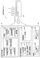
- FIG. 1 is a diagram for explaining the outline of the processing of the load leveling apparatus 10 according to the present embodiment.
- VM generation, deletion, migration, etc. are repeated.
- the load may be biased among the computes that make up the virtualization infrastructure.
- Active VM has a high load because it is in charge of request processing, but Standby VM has a low load and the load is likely to be biased.
- the load leveling apparatus 10 monitors the load of each host (compute) and detects load imbalance when an application that adopts the ACT / SBY configuration is installed in a VM of a virtualization platform. To do.
- the load leveling apparatus 10 reduces the load bias by switching the system between Active VM (the VM of the ACT system) and Standby VM (the VM of the SBY system) when detecting the load bias.
- the VM “# 1” (ACT) and the VM “# 11” (SBY) form a redundant pair, and similarly, the VM “# 2” (ACT) and the VM “# 22” (SBY). ), VM “# 3” (ACT) and VM “# 33” (SBY), and VM “# 4” (ACT) and VM “# 44” (SBY) are redundant pairs.
- the compute “# 1” has a large load because a large number of ACT VMs are arranged (see reference numeral A).
- the compute “# 4” has a low load because a large number of SBY VMs are arranged (see symbol B).
- a VM here, VM “# 1” arranged in a compute (compute “# 1”) having a high load and a compute (compute “# 4”) having a low load.
- the load leveling is realized by performing system switching between Active VM and Standby VM in the pair of VMs (VM “# 11” in this case) arranged in).
- the load leveling apparatus 10 balances the load between the hosts (compute) by reducing the influence on the service regardless of the application limitation of the virtualization method. Can be realized.
- FIG. 2 is a diagram showing a configuration of the load leveling system 1 including the load leveling apparatus 10 according to the present embodiment.
- a plurality of computes 30 physical resources: hosts (computers) on which VMs operate), a virtualization platform control device (virtualization platform) 20, and a load leveling system 10 connect networks and the like. Connected via communication.
- One or more VMs 3 can be built in the compute 30 as a virtual environment under the control of the virtualization platform controller 20. Further, one or more applications can be arranged (installed) in the VM 3 and provide a service based on a request from a user terminal (not shown).
- the virtualization platform control device 20 is communicatively connected to the load leveling device 10, each of the computes 30 and the like, and controls the VM 3 and allocates resources. Further, the virtualization platform control device 20 monitors the resources of each compute 30 and each VM 3.
- the load leveling apparatus 10 is communicatively connected to the virtualization platform control apparatus 20 and the like, acquires load information (load information) of each VM 3, and detects the load bias for each of the computes 30 when the load bias is detected. In order to reduce the above, the instruction information for the system switching of the ACT / SBY configuration of the VM 3 forming the pair is output.
- the virtualization platform control device 20 and the load leveling device 10 will be described in detail.
- the virtualization platform control device (virtualization platform) 20 is realized by a computer including a control unit, an input / output unit (none of which is shown), and a storage unit 23.
- the input / output unit includes a communication interface for transmitting / receiving information, and an input / output interface for transmitting / receiving information to / from an input device such as a touch panel or a keyboard or an output device such as a monitor.
- the storage unit 23 includes a flash memory, a hard disk, a RAM (Random Access Memory), and the like. As shown in FIG. 2, the storage unit 23 of the virtualization platform control device 20 stores a resource information repository 200 and a virtual machine image repository 250.
- the resource information repository 200 stores a resource management table 210 (resource management information) including information on VMs 3 (allocation destination information) constructed in each compute 30 (see FIG. 3 described later).
- the virtual machine image repository 250 stores a VM image which is a template for starting a virtual instance (VM) including the installed guest OS.
- control unit includes a resource payout control unit 21 and a monitoring function unit 22. It should be noted that this control unit also has other existing functions necessary for realizing the virtualization platform.
- the resource payout control unit 21 manages resources and allocates resources to the VM 3, and includes a resource management unit 211, a resource extraction / selection unit 212, and a virtual machine control unit 213.
- the resource management unit 211 manages the resource status of each compute 30 (host) using the resource management table 210 (see FIG. 3).
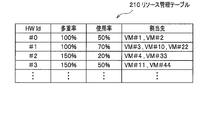
- FIG. 3 is a diagram showing an example of the data configuration of the resource management table 210 (resource management information) according to this embodiment.
- information on “allocation destination” of the VM 3 is stored in association with “HWId” that is identification information of the compute 30 (physical resource). For example, as shown in FIG. 3, it is indicated that the VM “# 1” and the VM “# 2” are allocated to the compute 30 of the HWId “# 0”.
- the resource management table 210 may store the “multiplication rate” and the “usage rate” of the compute 30 in association with the “HWId”.
- the “multiplication rate” is the ratio of the CPU performance of the reference CPU to the CPU performance of each compute 30 (CPU performance ratio), and represents the upper limit of the “usage rate” of the allocatable CPU. As shown in FIG. 3, 100% is not an upper limit value for the value of this multiplex rate, and a value is set according to the performance ratio of the compute 30. In the high-performance compute 30, a value larger than 100% (for example, "150%") is set. As a result, even in a system including the computes 30 (physical servers) having different performances, resources can be allocated based on one piece of resource request information.
- the “usage rate” indicates the cumulative CPU usage rate of the allocated virtual CPUs.
- the resource extraction / selection unit 212 When the resource extraction / selection unit 212 receives the resource request information (VM activation request), the resource extraction / selection unit 212 extracts allocatable resources (allocation destination physical resource candidates), and selects a resource from the candidates according to a predetermined allocation policy. Select the allocation destination physical resource.
- the resource request information VM activation request
- the resource extraction / selection unit 212 extracts allocatable resources (allocation destination physical resource candidates), and selects a resource from the candidates according to a predetermined allocation policy. Select the allocation destination physical resource.
- the virtual machine control unit 213 activates the VM 3 for the compute 30 selected by the resource extraction / selection unit 212 using the VM image stored in the virtual machine image repository 250.
- the monitoring function unit 22 includes a resource monitoring unit 221 that monitors loads on the compute 30 and the VM 3.
- the resource monitoring unit 221 monitors, for example, the CPU usage rate and the memory usage rate of each of the computes 30 and the VM 3, acquires the load information, and stores the load information in the storage unit 23. Further, it is assumed that the resource monitoring unit 221 executes monitoring of the load of each of the computes 30 at a predetermined time interval (here, referred to as “monitoring interval ⁇ ”).
- the virtualization platform control device 20 also has a load leveling function by live migration (not shown) as a function of the existing virtualization platform. Also, the virtualization platform control device 20 has a function of returning the setting information such as the configuration of each compute 30 when the load leveling device 10 makes an inquiry about the setting information such as the configuration of each compute 30. Is also equipped.
- the load leveling system 1 including the load leveling apparatus 10 it is not necessary to modify the application or IF (interface) of the existing virtualization platform (virtualization platform control device 20), and as it is. It is possible to realize the operation and function of the present invention by utilizing the above. Therefore, it is possible to reduce the burden of system modification by a system administrator or the like when executing the present invention.
- the load leveling apparatus 10 acquires the resource monitoring result information (load information) of the VM 3 from the virtualization platform control apparatus 20 or the like, calculates the load of the compute 30 (“host load” described below), and distributes the load. In the case of detecting ",” in order to reduce the bias of the load, the system switching instruction information of the ACT / SBY configuration of the paired VM3 is output.
- the load leveling apparatus 10 inquires of the virtualization platform control apparatus 20 about the setting information such as the configuration of each target compute 30, and acquires the setting information to determine whether or not the configuration allows live migration. To do. Then, when live migration is possible, the load leveling apparatus 10 compares (average value of) the system switching time and the migration time, and adopts the method with the shorter time to execute the load leveling. (See below for details).
- the load leveling apparatus 10 is realized by a computer including a control unit, an input / output unit (none of which is shown), and a storage unit 12.
- the input / output unit includes a communication interface for transmitting / receiving information, and an input / output interface for transmitting / receiving information to / from an input device such as a touch panel or a keyboard or an output device such as a monitor.
- the storage unit 12 is composed of a flash memory, a hard disk, a RAM and the like. As shown in FIG. 2, the redundant configuration management repository 100, the system switching time information 150, and the live migration time information 160 are stored in the storage unit 12 of the load leveling apparatus 10 (details will be described later). Further, the storage unit 12 temporarily stores a program (load leveling program) for executing each function of the control unit and information necessary for the processing of the control unit.
- a program load leveling program
- the control unit includes a load leveling function unit 11 and executes load leveling processing of each compute 30.
- the load leveling function unit 11 includes a redundant configuration management unit 111, a load determination unit 112, a VM placement determination unit 113, a switching instruction unit 114, and a leveling method setting unit 115.
- the redundant configuration management unit 111 is the information of the allocation destination of the resource management table 210 (FIG. 3) stored in the storage unit 23 (resource information repository 200) of the virtualization infrastructure control device 20, that is, the VM 3 constructed in the compute 30.
- the update information is acquired and the redundant configuration management table 110 (redundant configuration management information) stored in its own storage unit 12 (redundant configuration management repository 100) is updated.
- the redundant configuration management unit 111 obtains update information by inquiring of the virtualization infrastructure control device 20 at a predetermined time interval (for example, the monitoring interval ⁇ ) whether the resource management table 210 has been updated. Good. Further, when the resource management unit 211 of the virtualization infrastructure control device 20 updates the resource management table 210, the update information may be notified to the load leveling device 10.
- FIG. 4 is a diagram showing an example of the data configuration of the redundant configuration management table 110 (redundant configuration management information) according to this embodiment.
- the application name (App) and the application ID (App ID) are associated with each other, and the ID (identifier) (VM ID) of the VM 3 forming a redundant configuration pair and the application (App) thereof are associated with each other.
- the attached IP address (Virtual IP) is stored. As shown in FIG.
- a pair of redundant configurations (ACT / SBY configuration) of VM3 corresponding to an application whose application name (App) is “VNF1” and whose application ID (App ID) is “# 01” is It indicates that the VM 3 is a VM 3 having a VM ID “# 1” or “# 11” and its Virtual IP is “192.168.xx.xx”.
- system switching between Active VM and Standby VM may be executed depending not only on the state of the compute 30 and VM3, but also on individual requirements of the application (purpose such as maintenance and software upgrade). Therefore, in the resource management table 210 (FIG. 3) or the like provided in the virtualization platform controller 20 (virtualization platform) that does not consider individual requirements of the application, which VM3 is the ACT system or the SBY system ( App status) is not managed.
- the load leveling apparatus 10 side has a configuration in which the App state is not managed in the redundant configuration management table 110 and the like, and does not have a function of executing individual requirements of the application, which is common to various applications. The system that can be used for is realized.
- the load determination unit 112 calculates the “host load” as the load of each compute 30.
- the load determination unit 112 calculates the host load by the following (Equation 1).
- Host load (total value of VM load installed in host) / (capacity of host) ... (Equation 1)
- the load of the VM3 is the CPU usage rate of each VM3, and the capacity of the host is 100.
- the load determination unit 112 may directly acquire the load information of each VM 3 from each VM 3, or may acquire it from the virtualization infrastructure control device 20. Further, the load determination unit 112 executes the calculation of the host load at a preset time interval (for example, calculation interval ⁇ ).
- the calculation interval ⁇ is a constant multiple of the monitoring interval ⁇ .
- the load determination unit 112 may use the value of the load information of the VM 3 acquired at the closest time from the time of calculation of the load, or the average value of the past predetermined period. Alternatively, a weighted average value or the like may be used. The weighting of the weighted average value is performed by giving a higher weight to the latest t3 when there is data at times t1, t2, and t3 from the oldest.
- the load determination unit 112 calculates the standard deviation of the host loads of all hosts. When the calculated standard deviation of the host load is larger than the preset (predetermined) standard standard deviation ⁇ , the load determining unit 112 determines that the deviation of the load between the hosts is large, and information to that effect (see below). “Host load bias notification”) to the VM placement determination unit 113.
- the method of determining the bias of the load of the compute 30 (host) by the load determining unit 112 is not limited to the above method.
- the number of Active VMs and Standby VMs may be used as the load, and the number of Active VMs may be compared to determine the load bias.
- the VM placement determination unit 113 extracts the host (compute 30) having the largest average value of the host load in the predetermined period, and selects the VM 3 having the highest load in the host. Then, the VM placement determination unit 113 refers to the redundant configuration management table 110 (FIG. 4) and determines a VM (Standby VM) paired with the VM (Active VM) as a switching candidate. The VM placement determination unit 113 simulates and determines whether the average value of the host load becomes equal to or less than the index value ⁇ when the pair that is the switching candidate is switched.
- the VM placement determination unit 113 selects the VM3 having the next highest load and the VM3 of the pair in the host as a switching candidate, and the average value of the host load becomes the index value ⁇ or less. This process is repeated until. Then, the VM placement determination unit 113 determines a pair of switching candidates at the time when the average value of the host load becomes equal to or less than the index value ⁇ as a pair for system switching. The details will be described with reference to FIG. 7 described later.
- the method of determining the VM3 pair to be the system switching target by the VM placement determination unit 113 is not limited to the above method.
- the optimal / suboptimal system switching plan may be calculated by utilizing the existing solution method of the combinatorial optimization problem.
- the switching instruction unit 114 instructs the VM3 and the like to switch the system of the VM3 of the pair determined by the VM placement determination unit 113.
- the system switching may be performed automatically, or may be performed manually with the intervention of a system administrator.
- the system switching instruction may be given directly to the VM 3 or may be given to the VM 3 via an EMS (Element Management System) that manages the application.
- EMS Event Management System
- the leveling method setting unit 115 inquires of the virtualization platform control device 20 about the setting information such as the configuration of each target compute 30, and determines whether or not the configuration allows live migration. Note that the technology related to this determination is detailed in, for example, Non-Patent Document 4 (https://docs.openstack.org/nova/queens/admin/configuring-migrations.html#section-configuring-compute-migrations). Then, when the live migration is possible, the leveling method setting unit 115 performs the system switching indicating the time measured by the system switching before (past) that is performed by the system switching instruction of the load leveling apparatus 10. The time is compared with the time required for live migration (hereinafter referred to as “live migration time”), and the method with the shorter time is adopted as the load leveling method.
- live migration time the time required for live migration
- the leveling method setting unit 115 acquires the time taken for the system switching when the system switching is performed between the VMs 3 of the pair having the ACT / SBY configuration based on the instruction from the switching instruction unit 114. Then, the system switching time information 150 is stored in the storage unit 12. For example, the switching instruction unit 114 may acquire the system switching time together with the switching completion response.
- the system switching time information 150 may be the information measured by the application executed by the VM 3 or the information measured by the EMS.
- the switching instruction unit 114 may poll the application at predetermined time intervals to monitor the state and measure the switching time.
- the leveling method setting unit 115 acquires the live migration time executed by the load leveling method based on the existing live migration from the virtualization platform control device 20 or the like and stores it in the storage unit 12. I'll do it.
- the system administrator or the like verifies the live migration time in advance, and the leveling method setting unit 115 sets a fixed value from the result and stores it as the live migration time information 160 in the storage unit 12. You may do it.
- the leveling method setting unit 115 refers to the storage unit 12, calculates the average value of the system switching time of a predetermined time (period) using the system switching time information 150 and the live migration time information 160, and calculates the average value.
- the live migration time is compared with the average value of the system switching time for a predetermined time, and the load leveling method with the shorter time is adopted (set).
- the leveling method setting unit 115 transmits a setting instruction for enabling the load leveling function by live migration of the virtualization platform control device 20.
- the leveling technique setting unit 115 performs virtualization platform control.
- a setting instruction for disabling the load leveling function by live migration of the device 20 is transmitted.
- the load leveling apparatus 10 and the virtualization platform control apparatus 20 are described as separate apparatuses (separate housings). However, each configuration of the load leveling apparatus 10 described above is different from the virtualization platform control apparatus 20. May be incorporated into the device to be configured as one device (housing).
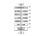
- FIG. 5 is a flowchart showing the flow of the VM 3 start-up process in the load leveling system 1 according to this embodiment.
- the resource payout control unit 21 of the virtualization platform control device 20 receives a new VM3 activation request (step S1). Note that, here, description will be made assuming that the activation request for the two VMs 3 forming a pair is made in the ACT / SBY configuration.
- the resource extraction / selection unit 212 of the resource payout control unit 21 refers to the resource management table 210 (FIG. 3) in the resource information repository 200 of the storage unit 23, and allocates the resource. (Allocation destination physical resource candidate) is extracted (step S2). Then, the resource extraction / selection unit 212 selects an allocation destination resource (compute 30) from the extracted candidates according to a predetermined allocation policy (step S3).
- the predetermined allocation policy for example, the Affinity rule or the Anti-Affinity rule is applied, the fixed allocation of the CPU (CPU Pinning) is applied, or the compute 30 with a small amount of resources used by the VM 3 that is already allocated is selected. Etc. are the rules.
- This predetermined allocation policy is an existing VM allocation destination selection method, and is detailed in Non-Patent Document 5 (https://docs.openstack.org/ocata/config-reference/compute/schedulers.html), for example.
- the resource management unit 211 updates the resource management table 210 (FIG. 3) in the resource information repository 200 (step S4). Specifically, the resource management unit 211 adds the VM ID of the VM 3 to be newly activated to the “allocation destination” column corresponding to the HWId of the selected compute 30. Here, the VM IDs of the two VM3s that make a pair are registered as the ACT / SBY configuration. Then, the resource management unit 211 notifies the load leveling apparatus 10 of update information indicating that the resource management table 210 has been updated.
- the redundant configuration management unit 111 of the load leveling apparatus 10 Upon receiving the update information from the virtualization platform controller 20, the redundant configuration management unit 111 of the load leveling apparatus 10 updates the redundant configuration management table 110 (FIG. 4) in the redundant configuration management repository 100 (step S5).
- the virtual machine control unit 213 of the virtualization platform control device 20 refers to the virtual machine image repository 250 in the storage unit 23 and uses the VM image corresponding to the compute 30 selected in step S4 to create a new one.
- the VM 3 is activated (step S6).
- the resource management unit 211 outputs the response information indicating that the new VM 3 has been activated (step S7), and the processing ends.
- the load leveling apparatus 10 acquires the update information and sets the redundant configuration management table 110 to It becomes possible to update to the latest state.
- FIG. 5 it has been described that the activation request for the two VMs 3 that make a pair as the ACT / SBY configuration is made at one time, but the VMs 3 that make a pair as the ACT / SBY configuration may be separately activated. Good.
- the resource management unit 211 of the virtualization platform control device 20 updates the load management information indicating that the resource management table 210 has been updated. Notifying the optimization device 10.
- FIG. 6 is a flowchart showing the flow of the load bias determination processing executed by the load leveling apparatus 10 according to this embodiment.
- the load determination unit 112 calculates the load (host load) of each compute 30 and calculates the standard deviation thereof. Then, the load determination unit 112 determines, based on the calculated host load, whether the load bias is larger than a preset (predetermined) standard standard deviation ⁇ , and if it is large, the load bias between the hosts is large. To determine.
- the resource monitoring unit 221 of the virtualization infrastructure control device 20 monitors the load of the host (compute 30) and the VM 3 at the monitoring interval ⁇ . The details will be described below.
- the load determination unit 112 acquires the load information (here, the CPU usage rate) of each VM 3 (step S11).
- the load determination unit 112 acquires the load information from the virtualization infrastructure control device 20, for example, at predetermined time intervals (for example, the monitoring interval ⁇ ). Then, the load determination unit 112 may determine the bias of the load using the load information stored in the storage unit 12, or may send the request information to the virtualization infrastructure control device 20 at every predetermined time interval.
- the load information may be acquired by transmitting.
- step S15 the load determination unit 112 calculates the host load of each host (compute 30) according to the above (Equation 1).
- the load of the VM3 is the CPU usage rate of each VM3, and the capacity of the host is calculated as 100.
- the value of the load acquired at the closest time from the time of calculation may be used, or the average value of the past predetermined period may be used. Alternatively, a weighted average value may be used.
- the load determination unit 112 calculates the standard deviation of the host load of each host (compute 30) (step S16). Then, the load determination unit 112 determines whether the calculated standard deviation of the host load is larger than a preset (predetermined) reference standard deviation ⁇ (step S17). Here, when the standard deviation of the host load is less than or equal to the standard standard deviation ⁇ (step S17 ⁇ No), the load determination unit 112 determines that the load bias of each host is not large, and returns to step S10. On the other hand, when the standard deviation of the host load is larger than the standard standard deviation ⁇ (step S17 ⁇ Yes), the load determination unit 112 determines that the bias of the loads of the hosts is large, and proceeds to the next step S18.
- step S18 the load determination unit 112 outputs information (host load bias notification) indicating that the load bias of each host 3 is large, to the VM placement determination unit 113, and ends the processing.
- information host load bias notification
- the load leveling apparatus 10 (load determining unit 112) can determine whether the load of each host is greater than a predetermined standard.
- FIG. 7 is a flowchart showing the flow of a system switching instruction output process executed by the load leveling apparatus 10 according to this embodiment.
- the VM placement determination unit 113 refers to the redundant configuration management table 110 (FIG. 4) when the load determination unit 112 acquires the information (host load bias notification) that the load bias of each host (compute 30) is large. , Switching candidates of the VM3 of the pair having the ACT / SBY configuration are calculated. Then, the switching instruction unit 114 outputs the system switching instruction information to the VM 3 of the pair calculated as the system switching target.
- FIG. 7 is a flowchart showing the flow of a system switching instruction output process executed by the load leveling apparatus 10 according to this embodiment.
- the VM placement determination unit 113 refers to the redundant configuration management table 110 (FIG. 4) when the load determination unit 112 acquires the information (host load bias notification) that the load bias of each host (compute 30) is large. , Switching candidates of the VM3 of the pair having the
- the VM placement determination unit 113 of the load leveling apparatus 10 determines that the load determination unit 112 determines that the load on each host (compute 30) is highly biased (host load bias). (Notification) is received (step S20).
- the VM placement determination unit 113 uses the host load information of each host (compute 30) for a predetermined period to determine the average value of the host load of each host (hereinafter referred to as the “host load average value”).
- the host having the largest host load average value is calculated and extracted (step S21).
- the VM placement determination unit 113 arranges the loads of the VMs 3 (hereinafter, referred to as “VM loads”) in descending order within the extracted host with the largest average host load value (step S22).
- VM loads the loads of the VMs 3
- the value of the load acquired at the closest time from the time of calculation may be used, or the average value of the past predetermined period may be used. Alternatively, a weighted average value may be used.
- the VM placement determination unit 113 determines whether the calculated host load average value is larger than a preset index value ⁇ of the host load average value (step S26).
- the process proceeds to step S27, and it is determined whether Y is equal to the number of VMs on the host.
- step S27 ⁇ Yes the system administrator or the like is notified that the load leveling process cannot be executed (load leveling NG) (step S28).
- step S27 ⁇ No the process returns to step S24 and continues.
- step S26 ⁇ No the switching instruction unit 114 selects one of all VM3 pairs for which the host load average value is calculated in step S25. One VM3 pair is selected, and a system switching instruction is output for that VM3 pair (step S30). The switching instruction unit 114 repeats the output of the system switching instruction of Step S30 for the pair of VM3 for which the VM placement determination unit 113 has calculated the host load average value in Step S25 (Steps S29 to S31), and ends the processing. ..
- the load leveling apparatus 10 can realize load leveling by the system switching processing regardless of the application limitation of the virtualization method, that is, even when live migration cannot be applied. ..
- FIG. 8 is a flowchart showing the flow of the leveling method setting process executed by the load leveling apparatus 10 according to this embodiment.
- the leveling method setting unit 115 determines whether or not the setting of the compute 30 is a live migration-enabled configuration. Then, when the leveling method setting unit 115 determines that live migration is possible, the average value of the system switching times related to the load leveling by the system switching of the VM 3 and the live migration time related to the load leveling by the live migration are set. And the shorter load leveling method is selected and set (validated).
- the leveling method setting process is executed at predetermined time intervals independently of the load bias determination process (FIG. 6) and the system switching instruction output process (FIG. 7) described above.
- the leveling method setting unit 115 of the load leveling apparatus 10 inquires of the virtualization platform control apparatus 20 about the setting information such as the config of the target compute 30, and acquires the setting information to determine whether the live migration is possible. The determination is made (step S40).
- the leveling method setting unit 115 ends the process. In this case, the load leveling apparatus 10 executes load leveling by switching the system of the VM3 pair.
- the leveling method setting unit 115 determines that the live migration is possible (step S40 ⁇ Yes)
- the leveling method setting unit 115 proceeds to the next step S41.
- step S41 the leveling method setting unit 115 determines whether or not a predetermined time has elapsed. Then, when the predetermined time has not elapsed (step S41 ⁇ No), the process waits until the predetermined time elapses. On the other hand, when the predetermined time has elapsed (step S41 ⁇ Yes), the process proceeds to the next step S42.
- step S42 the leveling method setting unit 115 acquires the system switching time between the Active VM and the Standby VM, which is measured on the application side, and stores it in the storage unit 12 as the system switching time information 150. Then, the leveling method setting unit 115 calculates the average value of the system switching time in a predetermined time (period).
- the leveling method setting unit 115 acquires the live migration time (step S43).
- This live migration time may be acquired by presetting information as a fixed value in the storage unit 12, or acquired by measuring the time required for live migration using the load leveling function of existing live migration. You may.
- the leveling method setting unit 115 compares the average value of the system switching times with the live migration time, and determines whether the average value of the system switching times is longer (step S44). If the average value of the system switching times is longer (step S44 ⁇ Yes), the leveling method setting unit 15 sets the leveling method to live migration. Specifically, the leveling method setting unit 15 switches the leveling method from system switching to live migration. That is, the leveling method setting unit 115 outputs instruction information for activating the load leveling function by live migration of the virtualization infrastructure control device 20 (step S45). Then, the process returns to step S41 to continue the process.
- the leveling method setting unit 15 sets the leveling method to system switching of the pair of VM3. To do. Specifically, the leveling method setting unit 115 determines whether the load leveling function by live migration of the virtualization platform controller 20 is valid, and if it is valid, the load leveling function by live migration is disabled. (Step S46). As a result, the load leveling function unit 11 is set to execute the load leveling process by switching the system, and the process returns to step S41 to continue the process.
- the load leveling apparatus 10 compares the average value of the system switching time with the live migration time and adopts the shorter load leveling method, so that the service is stopped by stopping the application or the like accompanying the load leveling. The influence can be further reduced.
- the load leveling apparatus 10 the load leveling method, and the load leveling program according to the present embodiment, in the virtualization platform, regardless of the application limitation of the virtualization method, the service can be provided. It is possible to reduce the influence of the above and realize the leveling of the load between the hosts (compute). In addition, since it can be used without modifying the existing virtualization platform control device 20 (virtualization platform), it is possible to reduce the burden of system modification by the system administrator or the like.
- VM virtual machine
Landscapes
- Engineering & Computer Science (AREA)
- Software Systems (AREA)
- Theoretical Computer Science (AREA)
- Physics & Mathematics (AREA)
- General Engineering & Computer Science (AREA)
- General Physics & Mathematics (AREA)
- Quality & Reliability (AREA)
- Hardware Redundancy (AREA)
Abstract
【課題】仮想化基盤において、仮想化手法の適用制限に関わりなく、かつ、サービスへの影響を低減して、ホスト(コンピュート)間の負荷の平準化を実現する。 【解決手段】負荷平準化装置10は、各VM3のコンピュート30に対する負荷情報を取得し、当該VM3が配置されているコンピュート30毎に合計して各コンピュート30の負荷を算出して各コンピュート30の負荷の標準偏差を算出し、算出した標準偏差が所定の基準標準偏差より大きい場合に、負荷の偏りが大きいと判定する負荷判定部112と、各コンピュート30の負荷のうち最も高い負荷のコンピュート30を抽出し、当該コンピュート30に配置されるVM3を選択し、選択したVM3とペアとなるVM3を特定して系切り替えをするペアのVMとして決定するVM配置決定部113と、決定したペアのVMについて系切り替えする指示情報を出力する切替指示部114と、を備える。
Description
本発明は、仮想化基盤におけるVM(Virtual Machine:仮想マシン)間の系切り替えを利用した負荷平準化装置、負荷平準化方法および負荷平準化プログラムに関する。
近年、通信サービスにおいて、仮想化技術を適用したネットワーク機能の仮想化(NFV:Network Functions Virtualization)の採用が進展している。ネットワークの仮想化は、従来専用のハードウェアを用いて実現されていたネットワーク機能をソフトウェア化して汎用サーバ上で動作させるように構成する。このようなネットワーク機能の仮想化技術をキャリア網に適用することで、経済的にスケーラビリティと信頼性を両立させることや、迅速なサービスの提供、サービス毎の需要に応じた柔軟なリソース割当、ハードウェアの寿命に縛られないサービス展開等が実現できると期待されている。
この仮想化技術を用いてサーバやネットワークといった物理資源を抽象化・隠蔽し、複数のアプリケーションやサービスに対して共通基盤を提供するシステムを仮想化基盤という。
仮想化基盤を実現する技術として、例えば、VMware vSphere(「VMware vSphere」は登録商標)と、OpenStack(「OpenStack」は登録商標)とが知られている。
VMware vSphereは、既存の仮想化基盤ソフトウェアの1つであり、そのうち、柔軟なリソース制御と稼働ホストの分散を実現する技術としてDRS(Distributed Resource Scheduler)がある(非特許文献1参照)。DRSでは、コンピュート毎に負荷を測定し、偏りが発生した場合にはライブマイグレーションにより負荷の高いコンピュートから低いコンピュートに対してVMを移行することで負荷を平準化させることが可能である。
VMware vSphereは、既存の仮想化基盤ソフトウェアの1つであり、そのうち、柔軟なリソース制御と稼働ホストの分散を実現する技術としてDRS(Distributed Resource Scheduler)がある(非特許文献1参照)。DRSでは、コンピュート毎に負荷を測定し、偏りが発生した場合にはライブマイグレーションにより負荷の高いコンピュートから低いコンピュートに対してVMを移行することで負荷を平準化させることが可能である。
OpenStackは、クラウド環境構築用のオープンソースソフトウェア群であり、そのうち、Watcherは、リソース最適化を目的とするコンポーネントである(非特許文献2参照)。このWatcherにより、コンピュートのロードアベレージや電力最適化の目標指標値を設定し、その達成に向けてマイグレーション等を自動で実行する。
一方、通信ソフトウェアの多くは、ACT(Active)/SBY(Standby)構成やN+M構成のようなHA(High Availability)構成を採用することにより可用性を高めている。例えば、ACT/SBY構成では、動作中(Active)コンポーネントと、待機中(Standby)コンポーネントとが存在し、Activeコンポーネントに障害が発生した場合には、Standbyコンポーネントが処理を引き継ぐことで、サービスの停止を防いだり、停止時間を極めて短い時間にしたりすることが可能である。
"vSphere DRS," [online],2018/10/3,VMware,Inc.,[平成30年10月25日検索],インターネット<URL:https://blogs.vmware.com/jp-cim/2014/02/vspheredrs.html>
"Watcher," [online],[平成30年10月25日検索],インターネット<URL:https://wiki.openstack.org/wiki/Watcher>
"SR-IOV," OpenStack Docs[online],[平成30年10月25日検索],インターネット<URL:https://docs.openstack.org/newton/networking-guide/config-sriov.html>
上記した仮想化基盤によるシステムにおいて、複数のアプリケーションを搭載した場合、VMの生成や削除、マイグレーション等が繰り返されることにより、仮想化基盤を構成するコンピュート間で負荷が偏るケースが発生することがある。
特に、ACT/SBY構成を採用するアプリケーションを仮想化基盤に搭載すると、Active VMはリクエスト処理を担当するため負荷が高いが、Standby VMは負荷が低い。そのため、負荷の偏りが発生し易い。このような負荷の偏りが発生すると、負荷の高いコンピュートに搭載されたアプリケーションに性能劣化等の影響がでる可能性がある。
特に、ACT/SBY構成を採用するアプリケーションを仮想化基盤に搭載すると、Active VMはリクエスト処理を担当するため負荷が高いが、Standby VMは負荷が低い。そのため、負荷の偏りが発生し易い。このような負荷の偏りが発生すると、負荷の高いコンピュートに搭載されたアプリケーションに性能劣化等の影響がでる可能性がある。
上記した非特許文献1に記載の技術には、コンピュート毎に負荷を測定し、偏りが発生した場合にはライブマイグレーションにより負荷の高いコンピュートから低いコンピュートに対してVMを移行することにより負荷を平準化させる仕組みが存在する。
しかしながら、性能要件の高いネットワーク機器の仮想化時にネットワークIO(Input/Output)の高速化と効率化を達成するため、例えばSR-IOV(Single Root I/O Virtualization)(非特許文献3参照)といった技術を利用することがあるが、仮想化基盤によっては、その際にライブマイグレーションを適用できない、といった制限(以下、「仮想化手法の適用制限」と称する。)が生じるケースが存在する。
また、VMのライブマイグレーションは、仮想ストレージ構成と割当リソース量によってはマイグレーションに時間がかかるため、負荷平準化のためにライブマイグレーションを頻度高く実行することに懸念がある場合がある。例えば、エフェメラルディスクを用いて仮想マシンインスタンスを起動しているときには、仮想ディスクイメージの内容を、移行前のインスタンスと移行後のインスタンス間で複製する処理(ブロックマイグレーション)が必要なため、時間がかかってしまう。
また、VMのライブマイグレーションは、仮想ストレージ構成と割当リソース量によってはマイグレーションに時間がかかるため、負荷平準化のためにライブマイグレーションを頻度高く実行することに懸念がある場合がある。例えば、エフェメラルディスクを用いて仮想マシンインスタンスを起動しているときには、仮想ディスクイメージの内容を、移行前のインスタンスと移行後のインスタンス間で複製する処理(ブロックマイグレーション)が必要なため、時間がかかってしまう。
このような点を鑑みて本発明がなされたのであり、本発明は、仮想化基盤において、仮想化手法の適用制限に関わりなく、かつ、サービスへの影響を低減して、ホスト(コンピュート)間の負荷の平準化を実現することができる、負荷平準化装置、負荷平準化方法および負荷平準化プログラムを提供することを課題とする。
前記した課題を解決するため、請求項1に記載の発明は、ACT(Active)/SBY(Standby)構成を採用するアプリケーションを、仮想化基盤の異なるコンピュート上に構築されたVM(Virtual Machine)に搭載し、Active VMとStandby VMとのペアのVMによる冗長構成とした際に、仮想化基盤と連携動作することで複数の前記コンピュートの負荷平準化を行う負荷平準化装置であって、前記アプリケーションに対応付けた、前記ペアとなるVMそれぞれの識別子を格納する冗長構成管理情報が記憶される記憶部と、各前記VMの前記コンピュートに対する負荷を示す負荷情報を取得し、前記負荷情報を当該VMが配置されている前記コンピュート毎に合計して各コンピュートの負荷を算出し、算出した各コンピュートの負荷の標準偏差を算出し、算出した標準偏差が所定の基準標準偏差より大きい場合に、前記コンピュート間の負荷の偏りが大きいと判定する負荷判定部と、前記コンピュート間の負荷の偏りが大きいと判定された場合に、前記算出した各コンピュートの負荷のうち最も高い負荷のコンピュートを抽出し、抽出した当該コンピュートに配置されるVMを選択し、前記選択したVMとペアとなるVMを前記冗長構成管理情報を参照して特定し、前記選択したVMと前記特定したそのペアとなるVMとを、Active VMとStandby VMとの系切り替えをするペアのVMとして決定するVM配置決定部と、前記決定したペアのVMについて系切り替えする指示情報を出力する切替指示部と、を備えることを特徴とする負荷平準化装置とした。
また、請求項4に記載の発明は、ACT(Active)/SBY(Standby)構成を採用するアプリケーションを、仮想化基盤の異なるコンピュート上に構築されたVM(Virtual Machine)に搭載し、Active VMとStandby VMとのペアのVMによる冗長構成とした際に、仮想化基盤と連携動作することで複数の前記コンピュートの負荷平準化を行う負荷平準化装置の負荷平準化方法であって、前記負荷平準化装置が、前記アプリケーションに対応付けた、前記ペアとなるVMそれぞれの識別子を格納する冗長構成管理情報が記憶される記憶部を備えており、各前記VMの前記コンピュートに対する負荷を示す負荷情報を取得し、前記負荷情報を当該VMが配置されている前記コンピュート毎に合計して各コンピュートの負荷を算出し、算出した各コンピュートの負荷の標準偏差を算出し、算出した標準偏差が所定の基準標準偏差より大きい場合に、前記コンピュート間の負荷の偏りが大きいと判定するステップと、前記コンピュート間の負荷の偏りが大きいと判定された場合に、前記算出した各コンピュートの負荷のうち最も高い負荷のコンピュートを抽出し、抽出した当該コンピュートに配置されるVMを選択し、前記選択したVMとペアとなるVMを前記冗長構成管理情報を参照して特定し、前記選択したVMと前記特定したそのペアとなるVMとを、Active VMとStandby VMとの系切り替えをするペアのVMとして決定するステップと、前記決定したペアのVMについて系切り替えする指示情報を出力するステップと、を実行することを特徴とする負荷平準化方法とした。
このようにすることで、負荷平準化装置は、VMの負荷情報を取得して、各コンピュートの負荷を算出し、算出した各コンピュートの負荷の標準偏差が所定の基準標準偏差より大きい場合に、コンピュート間の負荷の偏りが大きいと判定する。そして、負荷平準化装置は、負荷が最も高いコンピュートに配置されるVMを選択し、そのペアとなるVMとの間で系切り替えする指示情報を出力することができる。
よって、負荷平準化装置は、例えば、仮想化基盤において、SR-IOV等が設定されているような仮想化手法の適用制限がある場合であっても、コンピュート間の負荷平準化を実現することができる。
よって、負荷平準化装置は、例えば、仮想化基盤において、SR-IOV等が設定されているような仮想化手法の適用制限がある場合であっても、コンピュート間の負荷平準化を実現することができる。
請求項2に記載の発明は、前記VM配置決定部が、前記算出した各コンピュートの負荷のうち最も高い負荷のコンピュートを抽出したときに、抽出した当該コンピュートに配置されるVMのうち負荷の高い順にVMを選択し、前記選択したVMとペアとなるVMを前記冗長構成管理情報を参照して特定し、前記選択したVMとそのペアとなるVMとを系切り替えした場合の前記各コンピュートの負荷をシミュレーションし、前記シミュレーションした各コンピュートの負荷の標準偏差が前記所定の基準標準偏差以下になるまで前記抽出したコンピュートに配置されるVMの選択を繰り返して、前記系切り替えするペアのVMを決定すること、を特徴とする請求項1に記載の負荷平準化装置とした。
このようにすることで、負荷平準化装置は、所定の基準標準偏差以下になるように、系切り替えするペアのVMを決定するので、より確実に負荷の平準化を実現することができる。
請求項3に記載の発明は、前記記憶部には、前記コンピュートに配置されるVMを、他のコンピュートにライブマイグレーションした場合にかかる時間を示すライブマイグレーション時間と、過去において前記指示情報に基づき系切り替えした場合にかかった時間を示す系切り替え時間とが記憶されており、所定期間の前記系切り替え時間の平均値を算出し、算出した前記系切り替え時間の平均値と、前記ライブマイグレーション時間とを比較し、前記ライブマイグレーション時間の方が短ければ、ライブマイグレーションによる負荷平準化機能を有効にする設定情報を出力し、前記系切り替え時間の平均値の方が短ければ、前記ライブマイグレーションによる負荷平準化機能を無効にする設定情報を出力する平準化手法設定部を、さらに備えることを特徴とする請求項1または請求項2に記載の負荷平準化装置とした。
このように、負荷平準化装置は、系切り替え時間の平均値とライブマイグレーション時間とを比較して、短い方の負荷平準化手法を設定させることができる。よって、サービスへの影響をより低減して、コンピュート間の負荷の平準化を実現することができる。
請求項5に記載の発明は、コンピュータを、請求項1乃至請求項3のいずれか1項に記載の負荷平準化装置として機能させるための負荷平準化プログラムとした。
このようにすることにより、一般的なコンピュータを用いて、請求項1乃至請求項3のいずれか1項に記載の負荷平準化装置の各機能を実現することができる。
本発明によれば、仮想化基盤において、仮想化手法の適用制限に関わりなく、かつ、サービスへの影響を低減して、ホスト(コンピュート)間の負荷の平準化を実現する、負荷平準化装置、負荷平準化方法および負荷平準化プログラムを提供することができる。
次に、本発明を実施するための形態(以下、「本実施形態」と称する。)について説明する。まず、本実施形態に係る負荷平準化装置10(後記する図2参照)が実行する処理の概要を説明する。
<概要>
図1は、本実施形態に係る負荷平準化装置10の処理の概要を説明するための図である。
上記したように、仮想化基盤(後記する図2の「仮想化基盤制御装置20」)により、コンピュート(Compute)に複数のアプリケーションを搭載した場合、VM生成や削除、マイグレーション等が繰り返されることで、仮想化基盤を構成するコンピュート間で負荷が偏るケースが発生し得る。特に、ACT/SBY構成を採用するアプリケーションを仮想化基盤に搭載すると、Active VMは、リクエスト処理を担当するため負荷が高いが、Standby VMは負荷が低く負荷の偏りが発生しやすい。
そこで、本実施形態に係る負荷平準化装置10は、ACT/SBY構成を採用するアプリケーションを仮想化基盤のVMに搭載した際に、各ホスト(コンピュート)の負荷を監視し、負荷の偏りを検出する。そして、負荷平準化装置10は、負荷の偏りを検出した場合に、Active VM(ACT系のVM)とStandby VM(SBY系のVM)との系切り替えによって、負荷の偏りを低減することを特徴とする。
図1は、本実施形態に係る負荷平準化装置10の処理の概要を説明するための図である。
上記したように、仮想化基盤(後記する図2の「仮想化基盤制御装置20」)により、コンピュート(Compute)に複数のアプリケーションを搭載した場合、VM生成や削除、マイグレーション等が繰り返されることで、仮想化基盤を構成するコンピュート間で負荷が偏るケースが発生し得る。特に、ACT/SBY構成を採用するアプリケーションを仮想化基盤に搭載すると、Active VMは、リクエスト処理を担当するため負荷が高いが、Standby VMは負荷が低く負荷の偏りが発生しやすい。
そこで、本実施形態に係る負荷平準化装置10は、ACT/SBY構成を採用するアプリケーションを仮想化基盤のVMに搭載した際に、各ホスト(コンピュート)の負荷を監視し、負荷の偏りを検出する。そして、負荷平準化装置10は、負荷の偏りを検出した場合に、Active VM(ACT系のVM)とStandby VM(SBY系のVM)との系切り替えによって、負荷の偏りを低減することを特徴とする。
ここで、図1では、VM「#1」(ACT)とVM「#11」(SBY)が冗長構成のペアとなり、同様に、VM「#2」(ACT)とVM「#22」(SBY)、VM「#3」(ACT)とVM「#33」(SBY)、VM「#4」(ACT)とVM「#44」(SBY)が冗長構成のペアであるものとする。
この場合、図1(a)に示すように、コンピュート「#1」は、ACT系のVMが多く配置されているため、負荷が高くなっている(符号A参照)。一方、コンピュート「#4」は、SBY系のVMが多く配置されているため、負荷が低い(符号B参照)。このような負荷の偏りが発生すると、負荷の高いコンピュートに搭載されたアプリケーションに性能劣化といった影響が発生する可能性がある。
そこで、図1(b)に示すように、負荷の高いコンピュート(コンピュート「#1」)に配置されたVM(ここでは、VM「#1」)と、負荷が低いコンピュート(コンピュート「#4」)に配置されているペアのVM(ここでは、VM「#11」)とにおいて、Active VM とStandby VMの系切り替えを行うことにより、負荷の平準化を実現する。
この場合、図1(a)に示すように、コンピュート「#1」は、ACT系のVMが多く配置されているため、負荷が高くなっている(符号A参照)。一方、コンピュート「#4」は、SBY系のVMが多く配置されているため、負荷が低い(符号B参照)。このような負荷の偏りが発生すると、負荷の高いコンピュートに搭載されたアプリケーションに性能劣化といった影響が発生する可能性がある。
そこで、図1(b)に示すように、負荷の高いコンピュート(コンピュート「#1」)に配置されたVM(ここでは、VM「#1」)と、負荷が低いコンピュート(コンピュート「#4」)に配置されているペアのVM(ここでは、VM「#11」)とにおいて、Active VM とStandby VMの系切り替えを行うことにより、負荷の平準化を実現する。
このようにすることにより、本実施形態に係る負荷平準化装置10は、仮想化手法の適用制限に関わりなく、かつ、サービスへの影響を低減して、ホスト(コンピュート)間の負荷の平準化を実現することができる。
<本実施形態>
次に、負荷平準化装置10を含む負荷平準化システム1について説明する。
図2は、本実施形態に係る負荷平準化装置10を含む負荷平準化システム1の構成を示す図である。
負荷平準化システム1は、複数のコンピュート30(物理リソース:VMが動作するホスト(コンピュータ))と、仮想化基盤制御装置(仮想化基盤)20と、負荷平準化装置10とが、ネットワーク等を介して通信接続される。
次に、負荷平準化装置10を含む負荷平準化システム1について説明する。
図2は、本実施形態に係る負荷平準化装置10を含む負荷平準化システム1の構成を示す図である。
負荷平準化システム1は、複数のコンピュート30(物理リソース:VMが動作するホスト(コンピュータ))と、仮想化基盤制御装置(仮想化基盤)20と、負荷平準化装置10とが、ネットワーク等を介して通信接続される。
コンピュート30には、仮想化基盤制御装置20の制御に基づき、仮想化環境として1つ以上のVM3を構築することができる。また、VM3には、1つ以上のアプリケーションが配置(搭載)することができ、ユーザ端末(図示省略)からの要求に基づくサービスを提供する。
仮想化基盤制御装置20は、負荷平準化装置10、各コンピュート30等に通信接続され、VM3の制御やリソースの割り当て等を行う。また、仮想化基盤制御装置20は、各コンピュート30および各VM3のリソース監視を行う。
負荷平準化装置10は、仮想化基盤制御装置20等と通信接続され、各VM3の負荷の情報(負荷情報)を取得し、各コンピュート30について負荷の偏りを検出した場合に、その負荷の偏りを低減するため、ペアとなるVM3のACT/SBY構成の系切り替えの指示情報を出力する。
以下、仮想化基盤制御装置20と、負荷平準化装置10について、詳細に説明する。
仮想化基盤制御装置20は、負荷平準化装置10、各コンピュート30等に通信接続され、VM3の制御やリソースの割り当て等を行う。また、仮想化基盤制御装置20は、各コンピュート30および各VM3のリソース監視を行う。
負荷平準化装置10は、仮想化基盤制御装置20等と通信接続され、各VM3の負荷の情報(負荷情報)を取得し、各コンピュート30について負荷の偏りを検出した場合に、その負荷の偏りを低減するため、ペアとなるVM3のACT/SBY構成の系切り替えの指示情報を出力する。
以下、仮想化基盤制御装置20と、負荷平準化装置10について、詳細に説明する。
≪仮想化基盤制御装置≫
仮想化基盤制御装置(仮想化基盤)20は、制御部、入出力部(いずれも図示省略)および記憶部23を備えるコンピュータ等により実現される。
入出力部は、情報の送受信を行うための通信インタフェース、および、タッチパネルやキーボード等の入力装置や、モニタ等の出力装置との間で情報の送受信を行うための入出力インタフェースからなる。
仮想化基盤制御装置(仮想化基盤)20は、制御部、入出力部(いずれも図示省略)および記憶部23を備えるコンピュータ等により実現される。
入出力部は、情報の送受信を行うための通信インタフェース、および、タッチパネルやキーボード等の入力装置や、モニタ等の出力装置との間で情報の送受信を行うための入出力インタフェースからなる。
記憶部23は、フラッシュメモリやハードディスク、RAM(Random Access Memory)等により構成される。この仮想化基盤制御装置20の記憶部23には、図2に示すように、リソース情報リポジトリ200と仮想マシンイメージリポジトリ250とが記憶される。
リソース情報リポジトリ200には、各コンピュート30に構築するVM3の情報(割当先の情報)を含むリソース管理テーブル210(リソース管理情報)が格納される(後記する図3参照)。また、仮想マシンイメージリポジトリ250には、インストール済みのゲストOSを含む仮想インスタンス(VM)を起動するためのテンプレートであるVMイメージが格納される。
リソース情報リポジトリ200には、各コンピュート30に構築するVM3の情報(割当先の情報)を含むリソース管理テーブル210(リソース管理情報)が格納される(後記する図3参照)。また、仮想マシンイメージリポジトリ250には、インストール済みのゲストOSを含む仮想インスタンス(VM)を起動するためのテンプレートであるVMイメージが格納される。
また、制御部は、図2に示すように、リソース払出制御部21と、監視機能部22とを含んで構成される。なお、この制御部には、仮想化基盤を実現するために必要となる他の既存機能も備える。
リソース払出制御部21は、リソースの管理とVM3へのリソースの割り当てを行い、リソース管理部211、リソース抽出・選定部212、仮想マシン制御部213を備える。
リソース払出制御部21は、リソースの管理とVM3へのリソースの割り当てを行い、リソース管理部211、リソース抽出・選定部212、仮想マシン制御部213を備える。
リソース管理部211は、各コンピュート30(ホスト)のリソース状況を、リソース管理テーブル210(図3参照)を用いて管理する。
図3は、本実施形態に係るリソース管理テーブル210(リソース管理情報)のデータ構成の一例を示す図である。
リソース管理テーブル210には、コンピュート30(物理リソース)の識別情報である「HWId」に対応付けて、VM3の「割当先」の情報が格納される。
例えば、図3に示すように、HWId「#0」のコンピュート30に、VM「#1」とVM「#2」が割り当てられていることを示している。
リソース管理テーブル210には、コンピュート30(物理リソース)の識別情報である「HWId」に対応付けて、VM3の「割当先」の情報が格納される。
例えば、図3に示すように、HWId「#0」のコンピュート30に、VM「#1」とVM「#2」が割り当てられていることを示している。
また、このリソース管理テーブル210には、「HWId」に対応付けて、そのコンピュート30の「多重率」や「使用率」を格納するようにしてもよい。
「多重率」は、基準となるCPUのCPU性能と各コンピュート30のCPU性能の比率(CPU性能比率)であり、割当可能なCPUの「使用率」の上限を表わすものである。この多重率の値は、図3に示すように、100%が上限値ではなく、コンピュート30の性能比率に応じて値が設定される。高性能なコンピュート30では、100%より大きな値(例えば、「150%」)を設定する。これにより、性能の異なるコンピュート30(物理サーバ)で構成されるシステムにおいても、一つのリソース要求情報に基づいて、リソースを割り当てることができる。
「使用率」は、割当済みの仮想CPUについて累積したCPU使用率を示す。
「多重率」は、基準となるCPUのCPU性能と各コンピュート30のCPU性能の比率(CPU性能比率)であり、割当可能なCPUの「使用率」の上限を表わすものである。この多重率の値は、図3に示すように、100%が上限値ではなく、コンピュート30の性能比率に応じて値が設定される。高性能なコンピュート30では、100%より大きな値(例えば、「150%」)を設定する。これにより、性能の異なるコンピュート30(物理サーバ)で構成されるシステムにおいても、一つのリソース要求情報に基づいて、リソースを割り当てることができる。
「使用率」は、割当済みの仮想CPUについて累積したCPU使用率を示す。
リソース抽出・選定部212は、リソース要求情報(VMの起動要求)を受け付けた場合に、割当可能なリソース(割当先物理リソース候補)を抽出し、その候補の中から、所定の割当ポリシにより、割当先物理リソースを選定する。
仮想マシン制御部213は、リソース抽出・選定部212が選定したコンピュート30について、仮想マシンイメージリポジトリ250に記憶されたVMイメージを用いて、VM3を起動する。
監視機能部22は、コンピュート30およびVM3の負荷を監視するリソース監視部221を備える。
リソース監視部221は、例えば、各コンピュート30やVM3のCPU使用率、メモリ使用率等を監視し、負荷情報として取得して記憶部23に記憶する。また、リソース監視部221は、各コンピュート30の負荷の監視を予め設定した所定の時間間隔(ここでは、「監視間隔α」とする。)で実行しているものとする。
リソース監視部221は、例えば、各コンピュート30やVM3のCPU使用率、メモリ使用率等を監視し、負荷情報として取得して記憶部23に記憶する。また、リソース監視部221は、各コンピュート30の負荷の監視を予め設定した所定の時間間隔(ここでは、「監視間隔α」とする。)で実行しているものとする。
この仮想化基盤制御装置20は、既存の仮想化基盤が備える機能として、他に、ライブマイグレーションによる負荷平準化機能(図示省略)を備えている。また、仮想化基盤制御装置20は、負荷平準化装置10から各コンピュート30のコンフィグ(Configuration)等の設定情報の問合せがあった場合に、その各コンピュート30のコンフィグ等の設定情報を返信する機能も備えている。
なお、本実施形態に係る負荷平準化装置10を含む負荷平準化システム1では、既存の仮想化基盤(仮想化基盤制御装置20)のアプリケーションやIF(インタフェース)に修正を加える必要がなく、そのまま利用して本発明の作用・機能を実現することができる。よって、本発明を実行する際のシステム管理者等によるシステム改変の負担を軽減することができる。
なお、本実施形態に係る負荷平準化装置10を含む負荷平準化システム1では、既存の仮想化基盤(仮想化基盤制御装置20)のアプリケーションやIF(インタフェース)に修正を加える必要がなく、そのまま利用して本発明の作用・機能を実現することができる。よって、本発明を実行する際のシステム管理者等によるシステム改変の負担を軽減することができる。
≪負荷平準化装置≫
負荷平準化装置10は、仮想化基盤制御装置20等からVM3のリソース監視の結果情報(負荷情報)を取得して、コンピュート30の負荷(後記する「ホスト負荷」)を算出し、負荷の偏りを検出した場合に、その負荷の偏りを低減するため、ペアとなるVM3のACT/SBY構成の系切り替えの指示情報を出力する。
なお、負荷平準化装置10は、仮想化基盤制御装置20に対し、対象とする各コンピュート30のコンフィグ(Configuration)等の設定情報を問い合わせて取得し、ライブマイグレーションが可能な構成か否かを判定する。そして、負荷平準化装置10は、ライブマイグレーションが可能な場合は、系切り替え時間(の平均値)とマイグレーション時間とを比較し、より時間の短い方の手法を採用して負荷平準化を実行させる(詳細は後記)。
負荷平準化装置10は、仮想化基盤制御装置20等からVM3のリソース監視の結果情報(負荷情報)を取得して、コンピュート30の負荷(後記する「ホスト負荷」)を算出し、負荷の偏りを検出した場合に、その負荷の偏りを低減するため、ペアとなるVM3のACT/SBY構成の系切り替えの指示情報を出力する。
なお、負荷平準化装置10は、仮想化基盤制御装置20に対し、対象とする各コンピュート30のコンフィグ(Configuration)等の設定情報を問い合わせて取得し、ライブマイグレーションが可能な構成か否かを判定する。そして、負荷平準化装置10は、ライブマイグレーションが可能な場合は、系切り替え時間(の平均値)とマイグレーション時間とを比較し、より時間の短い方の手法を採用して負荷平準化を実行させる(詳細は後記)。
負荷平準化装置10は、制御部、入出力部(いずれも図示省略)および記憶部12を備えるコンピュータ等により実現される。
入出力部は、情報の送受信を行うための通信インタフェース、および、タッチパネルやキーボード等の入力装置や、モニタ等の出力装置との間で情報の送受信を行うための入出力インタフェースからなる。
入出力部は、情報の送受信を行うための通信インタフェース、および、タッチパネルやキーボード等の入力装置や、モニタ等の出力装置との間で情報の送受信を行うための入出力インタフェースからなる。
記憶部12は、フラッシュメモリやハードディスク、RAM等により構成される。この負荷平準化装置10の記憶部12には、図2に示すように、冗長構成管理リポジトリ100と、系切替時間情報150と、ライブマイグレーション時間情報160とが記憶される(詳細は後記)。また、この記憶部12には、制御部の各機能を実行させるためのプログラム(負荷平準化プログラム)や、制御部の処理に必要な情報が一時的に記憶される。
また、制御部は、図2に示すように、負荷平準化機能部11を備えており、各コンピュート30の負荷平準化処理を実行する。
この負荷平準化機能部11は、冗長構成管理部111と、負荷判定部112と、VM配置決定部113と、切替指示部114と、平準化手法設定部115とを含んで構成される。
この負荷平準化機能部11は、冗長構成管理部111と、負荷判定部112と、VM配置決定部113と、切替指示部114と、平準化手法設定部115とを含んで構成される。
冗長構成管理部111は、仮想化基盤制御装置20の記憶部23(リソース情報リポジトリ200)に格納されたリソース管理テーブル210(図3)の割当先の情報、つまり、コンピュート30に構築されるVM3の情報が更新された場合に、この更新情報を取得し、自身の記憶部12(冗長構成管理リポジトリ100)に格納された冗長構成管理テーブル110(冗長構成管理情報)を更新する。なお、冗長構成管理部111は、所定の時間間隔(例えば、監視間隔α)で、リソース管理テーブル210が更新されたか否かを仮想化基盤制御装置20に問い合わせることにより、更新情報を取得してもよい。また、仮想化基盤制御装置20のリソース管理部211が、リソース管理テーブル210を更新した場合に、その更新情報を、負荷平準化装置10へ通知するように設定してもよい。
図4は、本実施形態に係る冗長構成管理テーブル110(冗長構成管理情報)のデータ構成の一例を示す図である。
冗長構成管理テーブル110には、アプリケーション名(App)およびアプリケーションID(App ID)に対応付けて、冗長構成のペアとなるVM3のID(識別子)(VM ID)と、そのアプリケーション(App)に対応付けたIPアドレス(Virtual IP)とが格納される。
図4に示すように、例えば、アプリケーション名(App)が「VNF1」でアプリケーションID(App ID)が「#01」のアプリケーションに対応する、VM3の冗長構成(ACT/SBY構成)のペアが、VM ID「#1」「#11」のVM3であり、そのVirtual IPが「192.168.xx.xx」であることを示している。
冗長構成管理テーブル110には、アプリケーション名(App)およびアプリケーションID(App ID)に対応付けて、冗長構成のペアとなるVM3のID(識別子)(VM ID)と、そのアプリケーション(App)に対応付けたIPアドレス(Virtual IP)とが格納される。
図4に示すように、例えば、アプリケーション名(App)が「VNF1」でアプリケーションID(App ID)が「#01」のアプリケーションに対応する、VM3の冗長構成(ACT/SBY構成)のペアが、VM ID「#1」「#11」のVM3であり、そのVirtual IPが「192.168.xx.xx」であることを示している。
なお、Active VMとStandby VMとの系切り替えは、コンピュート30やVM3の状態のみならず、アプリケーションの個別要件(メンテナンスやソフトウェアアップグレード等の目的)にも依存して実行されることがある。そのため、アプリケーションの個別要件を意識しない仮想化基盤制御装置20(仮想化基盤)が備えるリソース管理テーブル210(図3)等では、どちらのVM3がACT系であるかSBY系であるかの状態(App状態)を管理していない。これに伴い、負荷平準化装置10側においても、冗長構成管理テーブル110等においてApp状態の管理を行わない構成とし、アプリケーションの個別要件を実行する機能を備えないことにより、様々なアプリケーションに共通的に利用可能なシステムを実現可能としている。
図2に戻り、負荷判定部112は、各コンピュート30の負荷として、「ホスト負荷」を算出する。負荷判定部112は、ホスト負荷を次の(式1)により算出する。
ホスト負荷 = (ホストに搭載されているVMの負荷の合計値)/(ホストの容量) ・・・(式1)
ここで、例えば、CPU使用率を指標とした場合は、VM3の負荷は各VM3のCPU使用率となり、ホストの容量は100となる。
ホスト負荷 = (ホストに搭載されているVMの負荷の合計値)/(ホストの容量) ・・・(式1)
ここで、例えば、CPU使用率を指標とした場合は、VM3の負荷は各VM3のCPU使用率となり、ホストの容量は100となる。
負荷判定部112は、各VM3の負荷情報を、直接各VM3から取得するようにしてもよいし、仮想化基盤制御装置20から取得するようにしてもよい。
また、負荷判定部112は、ホスト負荷の算出を予め設定した所定の時間間隔(例えば、算出間隔β)で実行する。なお、算出間隔βは、監視間隔αの定数倍とする。
負荷判定部112は、各コンピュート30の負荷(ホスト負荷)について、負荷の算出時から最も近い時刻に取得したVM3の負荷情報の値を利用するようにしてもよいし、過去所定期間の平均値や重み付き平均値等を利用するようにしてもよい。この重み付き平均値の重みは、例えば、古い順から時刻t1,t2,t3のデータがある場合、最も新しいt3に、より高い重みを付けることにより行う。
また、負荷判定部112は、ホスト負荷の算出を予め設定した所定の時間間隔(例えば、算出間隔β)で実行する。なお、算出間隔βは、監視間隔αの定数倍とする。
負荷判定部112は、各コンピュート30の負荷(ホスト負荷)について、負荷の算出時から最も近い時刻に取得したVM3の負荷情報の値を利用するようにしてもよいし、過去所定期間の平均値や重み付き平均値等を利用するようにしてもよい。この重み付き平均値の重みは、例えば、古い順から時刻t1,t2,t3のデータがある場合、最も新しいt3に、より高い重みを付けることにより行う。
負荷判定部112は、各ホスト(コンピュート30)のホスト負荷を算出すると、全ホストのホスト負荷の標準偏差を算出する。そして、負荷判定部112は、算出したホスト負荷の標準偏差が、予め設定した(所定の)基準標準偏差γより大きい場合、ホスト間の負荷の偏りが大きいと判定し、その旨の情報(後記する「ホスト負荷偏り通知」)をVM配置決定部113に出力する。
なお、負荷判定部112によるコンピュート30(ホスト)の負荷の偏りの判定手法は、上記の手法に限定されない。例えば、Active VM、Standby VMの個数を負荷とし、この個数の比較を行うなどして負荷の偏りを判定してもよい。
VM配置決定部113は、所定期間のホスト負荷の平均値が最も大きいホスト(コンピュート30)を抽出し、そのホスト内で最も負荷の高いVM3を選択する。そして、VM配置決定部113は、冗長構成管理テーブル110(図4)を参照し、そのVM(Active VM)とペアになるVM(Standby VM)を切替候補として決定する。VM配置決定部113は、切替候補となったペアを切り替えた場合に、ホスト負荷の平均値が指標値δ以下になるかをシミュレーションして判定する。指標値δ以下にならない場合、VM配置決定部113は、当該ホスト内で次に負荷の高いVM3とそのペアのVM3を選択して切替候補とし、ホスト負荷の平均値が指標値δ以下になるまで、この処理を繰り返す。そして、VM配置決定部113は、ホスト負荷の平均値が指標値δ以下になった時点での切替候補のペアを、系切り替えのペアとして決定する。なお、詳細は、後記する図7を用いて説明する。
なお、VM配置決定部113による、系切り替えの対象となるVM3のペアの決定手法は、上記手法に限定されない。例えば、既存の組み合わせ最適化問題の解法を利用して最適/準最適な系切り替え案を算出するようにしてもよい。
切替指示部114は、VM配置決定部113が決定したペアのVM3についての系切り替えを、そのVM3等に対して指示する。
系切り替えの実行は、自動で行われるようにしてもよいし、システム管理者が介在して手動で行われるようにしてもよい。また、系切り替えの指示は、VM3に直接してもよいし、アプリケーションを管理するEMS(Element Management System)を経由してVM3に指示するようにしてもよい。
系切り替えの実行は、自動で行われるようにしてもよいし、システム管理者が介在して手動で行われるようにしてもよい。また、系切り替えの指示は、VM3に直接してもよいし、アプリケーションを管理するEMS(Element Management System)を経由してVM3に指示するようにしてもよい。
平準化手法設定部115は、対象とする各コンピュート30のコンフィグ等の設定情報を仮想化基盤制御装置20に問い合わせて取得し、ライブマイグレーションが可能な構成か否かを判定する。なお、この判定に関する技術は、例えば、非特許文献4(https://docs.openstack.org/nova/queens/admin/configuring-migrations.html#section-configuring-compute-migrations)に詳しい。そして、平準化手法設定部115は、ライブマイグレーションが可能である場合に、負荷平準化装置10の系切り替えの指示により行われたそれ以前(過去)の系切り替えで計測された時間を示す系切り替え時間と、ライブマイグレーションにかかる時間(以下、「ライブマイグレーション時間」と称する。)とを比較し、短い時間の方の手法を負荷平準化手法として採用する。
具体的には、平準化手法設定部115は、切替指示部114の指示に基づき、ACT/SBY構成のペアのVM3間で系切り替えが行われた場合に、その系切り替えにかかった時間を取得し、系切替時間情報150として、記憶部12に記憶しておく。例えば、切替指示部114が切り替え完了応答とともに、系切り替え時間を取得するようにしてもよい。
この系切替時間情報150は、VM3で実行されるアプリケーションにより測定した情報を取得してもよいし、EMSが測定した情報を取得するようにしてもよい。切替指示部114からアプリケーションに対して所定の時間間隔でポーリングすることにより状態を監視し、切替時間を測定するようにしてもよい。
この系切替時間情報150は、VM3で実行されるアプリケーションにより測定した情報を取得してもよいし、EMSが測定した情報を取得するようにしてもよい。切替指示部114からアプリケーションに対して所定の時間間隔でポーリングすることにより状態を監視し、切替時間を測定するようにしてもよい。
また、ライブマイグレーション時間に関しては、平準化手法設定部115が、既存のライブマイグレーションによる負荷平準化手法により実行されたライブマイグレーション時間を、仮想化基盤制御装置20等から取得し、記憶部12に記憶しておく。または、システム管理者等がライブマイグレーション時間について事前の検証をしておき、平準化手法設定部115は、その結果から固定値を設定し、ライブマイグレーション時間情報160として記憶部12に記憶しておくようにしてもよい。
平準化手法設定部115は、記憶部12を参照し、系切替時間情報150とライブマイグレーション時間情報160とを用いて、所定時間(期間)の系切替時間の平均値を算出し、その算出した所定時間の系切替時間の平均値とライブマイグレーション時間とを比較し、時間の短い方の負荷平準化手法を採用(設定)する。
なお、負荷平準化手法を、ライブマイグレーションに切り替える際には、仮想化基盤制御装置20のライブマイグレーションによる負荷平準化機能を有効にする設定指示を、平準化手法設定部115が送信する。また、平準化手法設定部115は、一度仮想化基盤制御装置20のライブマイグレーションによる負荷平準化機能を有効にした後において、系切り替えによる負荷平準化手法を採用した場合には、仮想化基盤制御装置20のライブマイグレーションによる負荷平準化機能を無効にする設定指示を送信する。
このようにすることにより、負荷平準化に伴うアプリケーションの停止等によるサービスへの影響を、より低減する負荷平準化手法を設定することができる。
このようにすることにより、負荷平準化に伴うアプリケーションの停止等によるサービスへの影響を、より低減する負荷平準化手法を設定することができる。
なお、図2においては、負荷平準化装置10と仮想化基盤制御装置20とを別装置(別筺体)として説明したが、上記した負荷平準化装置10の各構成を、仮想化基盤制御装置20に組み込んで一つの装置(筺体)として構成するようにしてもよい。
<処理の流れ>
次に、負荷平準化装置10が実行する処理の流れについて、図5~図8を参照して説明する。まず、図5を参照して、仮想化基盤制御装置20によるVM3の起動処理について説明する。例えば、このVM3の起動処理を契機として、負荷平準化装置10の記憶部12(冗長構成管理リポジトリ100)内の冗長構成管理テーブル110(図4)が更新される。
次に、負荷平準化装置10が実行する処理の流れについて、図5~図8を参照して説明する。まず、図5を参照して、仮想化基盤制御装置20によるVM3の起動処理について説明する。例えば、このVM3の起動処理を契機として、負荷平準化装置10の記憶部12(冗長構成管理リポジトリ100)内の冗長構成管理テーブル110(図4)が更新される。
(VMの起動処理に伴う冗長構成管理テーブルの更新)
図5は、本実施形態に係る負荷平準化システム1におけるVM3の起動処理の流れを示すフローチャートである。
まず、仮想化基盤制御装置20のリソース払出制御部21が新たなVM3の起動要求を受け付ける(ステップS1)。なお、ここでは、ACT/SBY構成としてペアとなる2つのVM3の起動要求がなされたものとして説明する。
図5は、本実施形態に係る負荷平準化システム1におけるVM3の起動処理の流れを示すフローチャートである。
まず、仮想化基盤制御装置20のリソース払出制御部21が新たなVM3の起動要求を受け付ける(ステップS1)。なお、ここでは、ACT/SBY構成としてペアとなる2つのVM3の起動要求がなされたものとして説明する。
ステップS1において、起動要求を受け付けると、リソース払出制御部21のリソース抽出・選定部212は、記憶部23のリソース情報リポジトリ200内のリソース管理テーブル210(図3)を参照し、割当可能なリソース(割当先物理リソース候補)を抽出する(ステップS2)。そして、リソース抽出・選定部212が、その抽出された候補の中から、所定の割当ポリシにより、割当先となるリソース(コンピュート30)を選定する(ステップS3)。
所定の割当ポリシは、例えば、AffinityルールやAnti-Affinityルールを適用したり、CPUの固定割当(CPU Pinning)を適用したり、既に割り当てられているVM3の使用リソース量の少ないコンピュート30を選択する等のルールである。この所定の割当ポリシは、既存のVMの割当先選定手法であり、例えば非特許文献5(https://docs.openstack.org/ocata/config-reference/compute/schedulers.html)に詳しい。
ステップS3において起動するVM3の割当先となるコンピュート30が選定されると、リソース管理部211は、リソース情報リポジトリ200内のリソース管理テーブル210(図3)を更新する(ステップS4)。具体的には、リソース管理部211が、選定したコンピュート30のHWIdに対応する「割当先」欄に、新たに起動させるVM3のVM IDを追加する。ここでは、ACT/SBY構成としてペアとなる2つのVM3のVM IDが登録される。
そして、リソース管理部211は、リソース管理テーブル210が更新されたことを示す更新情報を、負荷平準化装置10に通知する。
そして、リソース管理部211は、リソース管理テーブル210が更新されたことを示す更新情報を、負荷平準化装置10に通知する。
負荷平準化装置10の冗長構成管理部111は、仮想化基盤制御装置20から更新情報を受信すると、冗長構成管理リポジトリ100内の冗長構成管理テーブル110(図4)を更新する(ステップS5)。
続いて、仮想化基盤制御装置20の仮想マシン制御部213は、記憶部23内の仮想マシンイメージリポジトリ250を参照し、ステップS4において選択されたコンピュート30に対応するVMイメージを用いて、新たなVM3を起動する(ステップS6)。
そして、リソース管理部211が、新たなVM3が起動されたことを示す応答情報を出力し(ステップS7)、処理を終える。
そして、リソース管理部211が、新たなVM3が起動されたことを示す応答情報を出力し(ステップS7)、処理を終える。
このようにすることで、仮想化基盤制御装置20により、新たなVM3が起動され設定が更新される度に、負荷平準化装置10はその更新情報を取得して、冗長構成管理テーブル110を、最新の状態に更新することが可能となる。
なお、図5においては、ACT/SBY構成としてペアとなる2つのVM3の起動要求が一度になされたものとして説明したが、ACT/SBY構成としてペアとなるVM3を別々に起動させるようにしてもよい。その場合、各VM3それぞれについてリソース管理テーブル210(図3)を更新した後、仮想化基盤制御装置20のリソース管理部211が、リソース管理テーブル210が更新されたことを示す更新情報を、負荷平準化装置10に通知する。
なお、図5においては、ACT/SBY構成としてペアとなる2つのVM3の起動要求が一度になされたものとして説明したが、ACT/SBY構成としてペアとなるVM3を別々に起動させるようにしてもよい。その場合、各VM3それぞれについてリソース管理テーブル210(図3)を更新した後、仮想化基盤制御装置20のリソース管理部211が、リソース管理テーブル210が更新されたことを示す更新情報を、負荷平準化装置10に通知する。
(負荷偏り判定処理)
次に、負荷平準化装置10の負荷判定部112による負荷偏り判定処理について説明する。
図6は、本実施形態に係る負荷平準化装置10が実行する負荷偏り判定処理の流れを示すフローチャートである。
負荷判定部112は、各コンピュート30の負荷(ホスト負荷)を算出し、その標準偏差を算出する。そして、負荷判定部112は、算出したホスト負荷に基づき、負荷の偏りが予め設定した(所定の)基準標準偏差γより大きいか否かを判定し、大きい場合にホスト間の負荷の偏りが大きいと判定する。
なお、ここでは、仮想化基盤制御装置20のリソース監視部221が、監視間隔αでホスト(コンピュート30)とVM3の負荷を監視しているものとする。以下、具体的に説明する。
次に、負荷平準化装置10の負荷判定部112による負荷偏り判定処理について説明する。
図6は、本実施形態に係る負荷平準化装置10が実行する負荷偏り判定処理の流れを示すフローチャートである。
負荷判定部112は、各コンピュート30の負荷(ホスト負荷)を算出し、その標準偏差を算出する。そして、負荷判定部112は、算出したホスト負荷に基づき、負荷の偏りが予め設定した(所定の)基準標準偏差γより大きいか否かを判定し、大きい場合にホスト間の負荷の偏りが大きいと判定する。
なお、ここでは、仮想化基盤制御装置20のリソース監視部221が、監視間隔αでホスト(コンピュート30)とVM3の負荷を監視しているものとする。以下、具体的に説明する。
まず、負荷判定部112は、負荷の監視結果である負荷情報を取得する回数を制御するための定数Xに0を設定(X=0)する(ステップS10)。
次に、負荷判定部112は、各VM3の負荷情報(ここでは、CPU使用率とする。)を取得する(ステップS11)。負荷判定部112は、例えば、仮想化基盤制御装置20から、所定の時間間隔(例えば、監視間隔α)毎に、負荷情報を取得しておく。そして、負荷判定部112は、記憶部12内に記憶されたその負荷情報を用いて負荷の偏りを判定してもよいし、所定の時間間隔毎に、仮想化基盤制御装置20に要求情報を送信して負荷情報を取得してもよい。
続いて、負荷判定部112は、監視間隔αが経過(Wait=α)するまで待つ(ステップS12)。そして、負荷判定部112は、Xに1を加算(X=X+1)する(ステップS13)。
次に、負荷判定部112は、ホスト負荷算出のために事前に設定した算出間隔β(βは、αの定数倍)が経過したか否かを判定する。具体的には、負荷判定部112は、X=β/αが成り立つか否かにより算出間隔βが経過したか否かを判定する(ステップS14)。
ここで、X=β/αが成り立たなければ(ステップS14→No)、ステップS11に戻り、負荷情報の取得の処理を続ける。
一方、X=β/αが成り立てば(ステップS14→Yes)、次のステップS15に進む。
ここで、X=β/αが成り立たなければ(ステップS14→No)、ステップS11に戻り、負荷情報の取得の処理を続ける。
一方、X=β/αが成り立てば(ステップS14→Yes)、次のステップS15に進む。
ステップS15において、負荷判定部112は、各ホスト(コンピュート30)のホスト負荷を上記した(式1)により算出する。
ここで、CPU使用率を負荷の指標とした場合、VM3の負荷は、各VM3のCPU使用率であり、ホストの容量は100として算出する。
なお、負荷は、算出時から最も近い時刻に取得した負荷の値を用いてもよいし、過去の所定期間の平均値を用いてもよい。また、重み付き平均値を用いてもよい。
なお、負荷は、算出時から最も近い時刻に取得した負荷の値を用いてもよいし、過去の所定期間の平均値を用いてもよい。また、重み付き平均値を用いてもよい。
続いて、負荷判定部112は、各ホスト(コンピュート30)のホスト負荷の標準偏差を算出する(ステップS16)。
そして、負荷判定部112は、算出したホスト負荷の標準偏差が、予め設定した(所定の)基準標準偏差γより大きいか否かを判定する(ステップS17)。
ここで、ホスト負荷の標準偏差が、基準標準偏差γ以下の場合(ステップS17→No)、負荷判定部112は、各ホストの負荷の偏りが大きくないと判定し、ステップS10へ戻る。
一方、ホスト負荷の標準偏差が、基準標準偏差γより大きい場合(ステップS17→Yes)、負荷判定部112は、各ホストの負荷の偏りが大きいと判定し、次のステップS18へ進む。
そして、負荷判定部112は、算出したホスト負荷の標準偏差が、予め設定した(所定の)基準標準偏差γより大きいか否かを判定する(ステップS17)。
ここで、ホスト負荷の標準偏差が、基準標準偏差γ以下の場合(ステップS17→No)、負荷判定部112は、各ホストの負荷の偏りが大きくないと判定し、ステップS10へ戻る。
一方、ホスト負荷の標準偏差が、基準標準偏差γより大きい場合(ステップS17→Yes)、負荷判定部112は、各ホストの負荷の偏りが大きいと判定し、次のステップS18へ進む。
ステップS18において、負荷判定部112は、各ホスト3の負荷の偏りが大きいと判定した旨の情報(ホスト負荷偏り通知)を、VM配置決定部113に出力し、処理を終える。
このようにすることで、負荷平準化装置10(負荷判定部112)は、各ホストの負荷が所定の基準よりも大きくなっているか否かを判定することができる。
(系切り替え指示出力処理)
次に、負荷平準化装置10のVM配置決定部113と切替指示部114による系切り替え指示出力処理について説明する。
図7は、本実施形態に係る負荷平準化装置10が実行する系切り替え指示出力処理の流れを示すフローチャートである。
VM配置決定部113は、負荷判定部112により、各ホスト(コンピュート30)の負荷の偏りが大きい旨の情報(ホスト負荷偏り通知)を取得すると、冗長構成管理テーブル110(図4)を参照し、ACT/SBY構成となるペアのVM3の切替候補を算出する。そして、切替指示部114が、系切り替えの対象として算出したペアのVM3に対し、系切り替えの指示情報を出力する。以下、具体的に説明する。
次に、負荷平準化装置10のVM配置決定部113と切替指示部114による系切り替え指示出力処理について説明する。
図7は、本実施形態に係る負荷平準化装置10が実行する系切り替え指示出力処理の流れを示すフローチャートである。
VM配置決定部113は、負荷判定部112により、各ホスト(コンピュート30)の負荷の偏りが大きい旨の情報(ホスト負荷偏り通知)を取得すると、冗長構成管理テーブル110(図4)を参照し、ACT/SBY構成となるペアのVM3の切替候補を算出する。そして、切替指示部114が、系切り替えの対象として算出したペアのVM3に対し、系切り替えの指示情報を出力する。以下、具体的に説明する。
まず、負荷平準化装置10(負荷平準化機能部11)のVM配置決定部113は、負荷判定部112から各ホスト(コンピュート30)の負荷の偏りが大きいと判定した旨の情報(ホスト負荷偏り通知)を受信する(ステップS20)。
続いて、VM配置決定部113は、各ホスト(コンピュート30)における所定期間のホスト負荷の情報を用いて、各ホストのホスト負荷の平均値(以下、「ホスト負荷平均値」と称する。)を算出し、ホスト負荷平均値が最も大きいホストを抽出する(ステップS21)。
次に、VM配置決定部113は、抽出したホスト負荷平均値が最も大きいホスト内で、各VM3の負荷(以下、「VM負荷」と称する。)を降順に並べる(ステップS22)。
なお、このとき利用する各VM3のVM負荷は、算出時から最も近い時刻に取得した負荷の値を用いてもよいし、過去の所定期間の平均値を用いてもよい。また、重み付き平均値を用いてもよい。
なお、このとき利用する各VM3のVM負荷は、算出時から最も近い時刻に取得した負荷の値を用いてもよいし、過去の所定期間の平均値を用いてもよい。また、重み付き平均値を用いてもよい。
続いて、VM配置決定部113は、VM負荷の高いVM3を抽出する回数を制御するための定数Yに0を設定(Y=0)する(ステップS23)。そして、VM配置決定部113は、Yに1を加算(Y=Y+1)する(ステップS24)。
続いて、VM配置決定部113は、各VM3のうちVM負荷が高い順にY番目のVM3を抽出し、冗長構成管理テーブル110(図4)を参照して、抽出したVM3とペアとなるVM3、つまり、抽出したVM3について、ACT/SBY構成となるペアのVM3を特定する。
なお、Y=1の場合、VM配置決定部113は、各VM3のうちVM負荷が最も高いVM3を抽出し、そのペアのVM3を特定する。Y=2の場合、VM配置決定部113は、VM負荷が2番目に高いVM3を抽出し、そのペアのVM3を特定する。以下同様である。
そして、VM配置決定部113は、Y番目に特定したVM3のペアを系切り替えしたと仮定した場合のホスト負荷および所定期間のホスト負荷平均値を算出する(ステップS25)。
なお、Y=1の場合、VM配置決定部113は、各VM3のうちVM負荷が最も高いVM3を抽出し、そのペアのVM3を特定する。Y=2の場合、VM配置決定部113は、VM負荷が2番目に高いVM3を抽出し、そのペアのVM3を特定する。以下同様である。
そして、VM配置決定部113は、Y番目に特定したVM3のペアを系切り替えしたと仮定した場合のホスト負荷および所定期間のホスト負荷平均値を算出する(ステップS25)。
次に、VM配置決定部113は、算出したホスト負荷平均値が、予め設定したホスト負荷平均値の指標値δより大きいか否かを判定する(ステップS26)。
ここで、ホスト負荷平均値が指標値δより大きい場合(ステップS26→Yes)、ステップS27に進み、Yがホスト上のVM数と等しいか否かを判定する。そして、Yがホスト上のVM数と等しい場合には(ステップS27→Yes)、負荷平準化処理を実行できない旨(負荷平準化NG)をシステム管理者等に通知する(ステップS28)。一方、Yがホスト上のVM数と等しくない場合には(ステップS27→No)、ステップS24に戻り処理を続ける。
ここで、ホスト負荷平均値が指標値δより大きい場合(ステップS26→Yes)、ステップS27に進み、Yがホスト上のVM数と等しいか否かを判定する。そして、Yがホスト上のVM数と等しい場合には(ステップS27→Yes)、負荷平準化処理を実行できない旨(負荷平準化NG)をシステム管理者等に通知する(ステップS28)。一方、Yがホスト上のVM数と等しくない場合には(ステップS27→No)、ステップS24に戻り処理を続ける。
また、ステップS26において、ホスト負荷平均値が指標値δ以下である場合(ステップS26→No)、切替指示部114が、ステップS25においてホスト負荷平均値を算出したすべてのVM3のペアのうちの一つのVM3のペアを選択し、そのVM3のペアについて系切り替え指示を出力する(ステップS30)。なお、切替指示部114は、VM配置決定部113がステップS25において、ホスト負荷平均値を算出したVM3のペア分、ステップS30の系切り替え指示の出力を繰り返し(ステップS29~S31)、処理を終える。
このようにすることで、負荷平準化装置10は、仮想化手法の適用制限に関わりなく、つまり、ライブマイグレーションが適用できない場合であっても、系切り替え処理により負荷平準化を実現することができる。
(平準化手法設定処理)
次に、負荷平準化装置10の平準化手法設定部115が実行する平準化手法設定処理について説明する。
図8は、本実施形態に係る負荷平準化装置10が実行する平準化手法設定処理の流れを示すフローチャートである。
この平準化手法設定処理では、まず、平準化手法設定部115が、コンピュート30の設定がライブマイグレーション可能な構成か否かを判定する。そして、平準化手法設定部115は、ライブマイグレーションが可能と判定した場合に、VM3の系切り替えによる負荷平準化に係る系切り替え時間の平均値と、ライブマイグレーションによる負荷平準化に係るライブマイグレーション時間とを比較し、短い方の負荷平準化手法を選択して設定(有効化)する処理を行う。なお、この平準化手法設定処理は、上記した、負荷偏り判定処理(図6)および系切り替え指示出力処理(図7)とは独立して所定の時間間隔で実行される。
次に、負荷平準化装置10の平準化手法設定部115が実行する平準化手法設定処理について説明する。
図8は、本実施形態に係る負荷平準化装置10が実行する平準化手法設定処理の流れを示すフローチャートである。
この平準化手法設定処理では、まず、平準化手法設定部115が、コンピュート30の設定がライブマイグレーション可能な構成か否かを判定する。そして、平準化手法設定部115は、ライブマイグレーションが可能と判定した場合に、VM3の系切り替えによる負荷平準化に係る系切り替え時間の平均値と、ライブマイグレーションによる負荷平準化に係るライブマイグレーション時間とを比較し、短い方の負荷平準化手法を選択して設定(有効化)する処理を行う。なお、この平準化手法設定処理は、上記した、負荷偏り判定処理(図6)および系切り替え指示出力処理(図7)とは独立して所定の時間間隔で実行される。
まず、負荷平準化装置10の平準化手法設定部115は、対象とするコンピュート30のコンフィグ等の設定情報を仮想化基盤制御装置20に問い合わせて取得し、ライブマイグレーションが可能な構成か否かを判定する(ステップS40)。
ここで、ライブマイグレーション可能な構成でないと判定した場合(ステップS40→No)、平準化手法設定部115は、処理を終了する。この場合、負荷平準化装置10は、VM3のペアの系切り替えによる負荷平準化を実行する。
一方、平準化手法設定部115は、ライブマイグレーション可能な構成であると判定した場合には(ステップS40→Yes)、次のステップS41に進む。
ここで、ライブマイグレーション可能な構成でないと判定した場合(ステップS40→No)、平準化手法設定部115は、処理を終了する。この場合、負荷平準化装置10は、VM3のペアの系切り替えによる負荷平準化を実行する。
一方、平準化手法設定部115は、ライブマイグレーション可能な構成であると判定した場合には(ステップS40→Yes)、次のステップS41に進む。
ステップS41において、平準化手法設定部115は、所定の時間が経過したか否かを判定する。そして、所定の時間が経過していない場合には(ステップS41→No)、所定の時間が経過するまで待つ。一方、所定の時間が経過した場合は(ステップS41→Yes)、次のステップS42に進む。
ステップS42において、平準化手法設定部115は、アプリケーション側で計測している、Active VMとStandby VMとの系切り替え時間を取得し、記憶部12に系切替時間情報150として格納する。そして、平準化手法設定部115は、系切り替え時間について所定時間(期間)での平均値を算出する。
続いて、平準化手法設定部115は、ライブマイグレーション時間を取得する(ステップS43)。このライブマイグレーション時間は、記憶部12に固定値として予め設定された情報を取得するようにしてもよいし、ライブマイグレーションにかかる時間を、既存のライブマイグレーションによる負荷平準化機能により測定することにより取得してもよい。
次に、平準化手法設定部115は、系切り替え時間の平均値とライブマイグレーション時間とを比較し、系切り替え時間の平均値の方が長いか否かを判定する(ステップS44)。
ここで、系切り替え時間の平均値の方が長ければ(ステップS44→Yes)、平準化手法設定部15は、平準化手法をライブマイグレーションに設定する。具体的には、平準化手法設定部15は、平準化手法を系切り替えからライブマイグレーションに切り替える。即ち、平準化手法設定部115は、仮想化基盤制御装置20のライブマイグレーションによる負荷平準化機能を有効化する指示情報を出力する(ステップS45)。そして、ステップS41に戻り処理を続ける。
一方、系切り替え時間の平均値の方がライブマイグレーション時間より長くなければ(同じも含む)(ステップS44→No)、平準化手法設定部15は、平準化手法をVM3のペアの系切り替えに設定する。具体的には、平準化手法設定部115は、仮想化基盤制御装置20のライブマイグレーションによる負荷平準化機能が有効であるかを判定し、有効であれば、ライブマイグレーションによる負荷平準化機能を無効化する(ステップS46)。これにより、負荷平準化機能部11による系切り替えによる負荷平準化処理が実行される設定となり、ステップS41に戻り処理を続ける。
ここで、系切り替え時間の平均値の方が長ければ(ステップS44→Yes)、平準化手法設定部15は、平準化手法をライブマイグレーションに設定する。具体的には、平準化手法設定部15は、平準化手法を系切り替えからライブマイグレーションに切り替える。即ち、平準化手法設定部115は、仮想化基盤制御装置20のライブマイグレーションによる負荷平準化機能を有効化する指示情報を出力する(ステップS45)。そして、ステップS41に戻り処理を続ける。
一方、系切り替え時間の平均値の方がライブマイグレーション時間より長くなければ(同じも含む)(ステップS44→No)、平準化手法設定部15は、平準化手法をVM3のペアの系切り替えに設定する。具体的には、平準化手法設定部115は、仮想化基盤制御装置20のライブマイグレーションによる負荷平準化機能が有効であるかを判定し、有効であれば、ライブマイグレーションによる負荷平準化機能を無効化する(ステップS46)。これにより、負荷平準化機能部11による系切り替えによる負荷平準化処理が実行される設定となり、ステップS41に戻り処理を続ける。
このように、負荷平準化装置10は、系切り替え時間の平均値とライブマイグレーション時間とを比較し短い方の負荷平準化手法を採用するため、負荷平準化に伴うアプリケーションの停止等によるサービスへの影響をより低減することができる。
以上説明したように、本実施形態に係る、負荷平準化装置10、負荷平準化方法および負荷平準化プログラムによれば、仮想化基盤において、仮想化手法の適用制限に関わりなく、かつ、サービスへの影響を低減して、ホスト(コンピュート)間の負荷の平準化を実現することができる。また、既存の仮想化基盤制御装置20(仮想化基盤)の修正を加えることなく利用可能となるため、システム管理者等によるシステム改変の負担を軽減することもできる。
1 負荷平準化システム
3 VM(仮想マシン)
10 負荷平準化装置
11 負荷平準化機能部
12 記憶部
20 仮想化基盤制御装置
21 リソース払出制御部
22 監視機能部
23 記憶部
30 コンピュート(ホスト)
100 冗長構成管理リポジトリ
110 冗長構成管理テーブル(冗長構成管理情報)
111 冗長構成管理部
112 負荷判定部
113 VM配置決定部
114 切替指示部
115 平準化手法設定部
150 系切替時間情報
160 ライブマイグレーション時間情報
200 リソース情報リポジトリ
210 リソース管理テーブル(リソース管理情報)
211 リソース管理部
212 リソース抽出・選定部
213 仮想マシン制御部
221 リソース監視部
250 仮想マシンイメージリポジトリ
3 VM(仮想マシン)
10 負荷平準化装置
11 負荷平準化機能部
12 記憶部
20 仮想化基盤制御装置
21 リソース払出制御部
22 監視機能部
23 記憶部
30 コンピュート(ホスト)
100 冗長構成管理リポジトリ
110 冗長構成管理テーブル(冗長構成管理情報)
111 冗長構成管理部
112 負荷判定部
113 VM配置決定部
114 切替指示部
115 平準化手法設定部
150 系切替時間情報
160 ライブマイグレーション時間情報
200 リソース情報リポジトリ
210 リソース管理テーブル(リソース管理情報)
211 リソース管理部
212 リソース抽出・選定部
213 仮想マシン制御部
221 リソース監視部
250 仮想マシンイメージリポジトリ
Claims (5)
- ACT(Active)/SBY(Standby)構成を採用するアプリケーションを、仮想化基盤の異なるコンピュート上に構築されたVM(Virtual Machine)に搭載し、Active VMとStandby VMとのペアのVMによる冗長構成とした際に、仮想化基盤と連携動作することで複数の前記コンピュートの負荷平準化を行う負荷平準化装置であって、
前記アプリケーションに対応付けた、前記ペアとなるVMそれぞれの識別子を格納する冗長構成管理情報が記憶される記憶部と、
各前記VMの前記コンピュートに対する負荷を示す負荷情報を取得し、前記負荷情報を当該VMが配置されている前記コンピュート毎に合計して各コンピュートの負荷を算出し、算出した各コンピュートの負荷の標準偏差を算出し、算出した標準偏差が所定の基準標準偏差より大きい場合に、前記コンピュート間の負荷の偏りが大きいと判定する負荷判定部と、
前記コンピュート間の負荷の偏りが大きいと判定された場合に、前記算出した各コンピュートの負荷のうち最も高い負荷のコンピュートを抽出し、抽出した当該コンピュートに配置されるVMを選択し、前記選択したVMとペアとなるVMを前記冗長構成管理情報を参照して特定し、前記選択したVMと前記特定したそのペアとなるVMとを、Active VMとStandby VMとの系切り替えをするペアのVMとして決定するVM配置決定部と、
前記決定したペアのVMについて系切り替えする指示情報を出力する切替指示部と、
を備えることを特徴とする負荷平準化装置。 - 前記VM配置決定部は、
前記算出した各コンピュートの負荷のうち最も高い負荷のコンピュートを抽出したときに、抽出した当該コンピュートに配置されるVMのうち負荷の高い順にVMを選択し、前記選択したVMとペアとなるVMを前記冗長構成管理情報を参照して特定し、前記選択したVMとそのペアとなるVMとを系切り替えした場合の前記各コンピュートの負荷をシミュレーションし、前記シミュレーションした各コンピュートの負荷の標準偏差が前記所定の基準標準偏差以下になるまで前記抽出したコンピュートに配置されるVMの選択を繰り返して、前記系切り替えするペアのVMを決定すること、
を特徴とする請求項1に記載の負荷平準化装置。 - 前記記憶部には、前記コンピュートに配置されるVMを、他のコンピュートにライブマイグレーションした場合にかかる時間を示すライブマイグレーション時間と、過去において前記指示情報に基づき系切り替えした場合にかかった時間を示す系切り替え時間とが記憶されており、
所定期間の前記系切り替え時間の平均値を算出し、算出した前記系切り替え時間の平均値と、前記ライブマイグレーション時間とを比較し、前記ライブマイグレーション時間の方が短ければ、ライブマイグレーションによる負荷平準化機能を有効にする設定情報を出力し、前記系切り替え時間の平均値の方が短ければ、前記ライブマイグレーションによる負荷平準化機能を無効にする設定情報を出力する平準化手法設定部を、さらに備えること
を特徴とする請求項1または請求項2に記載の負荷平準化装置。 - ACT(Active)/SBY(Standby)構成を採用するアプリケーションを、仮想化基盤の異なるコンピュート上に構築されたVM(Virtual Machine)に搭載し、Active VMとStandby VMとのペアのVMによる冗長構成とした際に、仮想化基盤と連携動作することで複数の前記コンピュートの負荷平準化を行う負荷平準化装置の負荷平準化方法であって、
前記負荷平準化装置は、
前記アプリケーションに対応付けた、前記ペアとなるVMそれぞれの識別子を格納する冗長構成管理情報が記憶される記憶部を備えており、
各前記VMの前記コンピュートに対する負荷を示す負荷情報を取得し、前記負荷情報を当該VMが配置されている前記コンピュート毎に合計して各コンピュートの負荷を算出し、算出した各コンピュートの負荷の標準偏差を算出し、算出した標準偏差が所定の基準標準偏差より大きい場合に、前記コンピュート間の負荷の偏りが大きいと判定するステップと、
前記コンピュート間の負荷の偏りが大きいと判定された場合に、前記算出した各コンピュートの負荷のうち最も高い負荷のコンピュートを抽出し、抽出した当該コンピュートに配置されるVMを選択し、前記選択したVMとペアとなるVMを前記冗長構成管理情報を参照して特定し、前記選択したVMと前記特定したそのペアとなるVMとを、Active VMとStandby VMとの系切り替えをするペアのVMとして決定するステップと、
前記決定したペアのVMについて系切り替えする指示情報を出力するステップと、
を実行することを特徴とする負荷平準化方法。 - コンピュータを、請求項1乃至請求項3のいずれか1項に記載の負荷平準化装置として機能させるための負荷平準化プログラム。
Priority Applications (1)
| Application Number | Priority Date | Filing Date | Title |
|---|---|---|---|
| US17/288,080 US12039377B2 (en) | 2018-11-02 | 2019-10-29 | Load leveling device, load leveling method, and load leveling program |
Applications Claiming Priority (2)
| Application Number | Priority Date | Filing Date | Title |
|---|---|---|---|
| JP2018-207710 | 2018-11-02 | ||
| JP2018207710A JP7014130B2 (ja) | 2018-11-02 | 2018-11-02 | 負荷平準化装置、負荷平準化方法および負荷平準化プログラム |
Publications (1)
| Publication Number | Publication Date |
|---|---|
| WO2020090777A1 true WO2020090777A1 (ja) | 2020-05-07 |
Family
ID=70464449
Family Applications (1)
| Application Number | Title | Priority Date | Filing Date |
|---|---|---|---|
| PCT/JP2019/042265 Ceased WO2020090777A1 (ja) | 2018-11-02 | 2019-10-29 | 負荷平準化装置、負荷平準化方法および負荷平準化プログラム |
Country Status (3)
| Country | Link |
|---|---|
| US (1) | US12039377B2 (ja) |
| JP (1) | JP7014130B2 (ja) |
| WO (1) | WO2020090777A1 (ja) |
Cited By (1)
| Publication number | Priority date | Publication date | Assignee | Title |
|---|---|---|---|---|
| WO2022003932A1 (ja) * | 2020-07-03 | 2022-01-06 | 日本電信電話株式会社 | サーマルスロットリング抑止装置、サーマルスロットリング抑止方法、および、サーマルスロットリング抑止プログラム |
Families Citing this family (6)
| Publication number | Priority date | Publication date | Assignee | Title |
|---|---|---|---|---|
| CN114546100A (zh) * | 2022-03-16 | 2022-05-27 | 中国工商银行股份有限公司 | 一种数据中心供电调整方法及装置 |
| CN114466019B (zh) * | 2022-04-11 | 2022-09-16 | 阿里巴巴(中国)有限公司 | 分布式计算系统、负载均衡方法、设备及存储介质 |
| CN114744649A (zh) * | 2022-04-19 | 2022-07-12 | 北京百度网讯科技有限公司 | 云计算单元的控制方法、装置、设备、介质及程序产品 |
| US20240281301A1 (en) * | 2022-05-13 | 2024-08-22 | Rakuten Mobile, Inc. | Execution platform determination system and execution platform determination method |
| US20240272895A1 (en) * | 2022-05-13 | 2024-08-15 | Rakuten Mobile, Inc. | Replace system and replace method |
| CN117312023A (zh) * | 2022-06-24 | 2023-12-29 | 比亚迪股份有限公司 | 车辆的控制方法、车辆及计算机可读存储介质 |
Citations (2)
| Publication number | Priority date | Publication date | Assignee | Title |
|---|---|---|---|---|
| JP2016153929A (ja) * | 2015-02-20 | 2016-08-25 | 日本電信電話株式会社 | 分散システム、負荷分散方法及びプログラム |
| WO2016162916A1 (ja) * | 2015-04-06 | 2016-10-13 | 株式会社日立製作所 | 管理計算機およびリソース管理方法 |
Family Cites Families (3)
| Publication number | Priority date | Publication date | Assignee | Title |
|---|---|---|---|---|
| US8185893B2 (en) * | 2006-10-27 | 2012-05-22 | Hewlett-Packard Development Company, L.P. | Starting up at least one virtual machine in a physical machine by a load balancer |
| CN108989194B (zh) * | 2017-05-31 | 2021-07-09 | 微软技术许可有限责任公司 | 分布式IPSec网关 |
| US11579909B2 (en) * | 2018-07-31 | 2023-02-14 | Vmware, Inc. | Honoring resource scheduler constraints during maintenances |
-
2018
- 2018-11-02 JP JP2018207710A patent/JP7014130B2/ja active Active
-
2019
- 2019-10-29 WO PCT/JP2019/042265 patent/WO2020090777A1/ja not_active Ceased
- 2019-10-29 US US17/288,080 patent/US12039377B2/en active Active
Patent Citations (2)
| Publication number | Priority date | Publication date | Assignee | Title |
|---|---|---|---|---|
| JP2016153929A (ja) * | 2015-02-20 | 2016-08-25 | 日本電信電話株式会社 | 分散システム、負荷分散方法及びプログラム |
| WO2016162916A1 (ja) * | 2015-04-06 | 2016-10-13 | 株式会社日立製作所 | 管理計算機およびリソース管理方法 |
Cited By (3)
| Publication number | Priority date | Publication date | Assignee | Title |
|---|---|---|---|---|
| WO2022003932A1 (ja) * | 2020-07-03 | 2022-01-06 | 日本電信電話株式会社 | サーマルスロットリング抑止装置、サーマルスロットリング抑止方法、および、サーマルスロットリング抑止プログラム |
| JPWO2022003932A1 (ja) * | 2020-07-03 | 2022-01-06 | ||
| JP7416247B2 (ja) | 2020-07-03 | 2024-01-17 | 日本電信電話株式会社 | サーマルスロットリング抑止装置、サーマルスロットリング抑止方法、および、サーマルスロットリング抑止プログラム |
Also Published As
| Publication number | Publication date |
|---|---|
| JP7014130B2 (ja) | 2022-02-01 |
| JP2020071840A (ja) | 2020-05-07 |
| US20210373968A1 (en) | 2021-12-02 |
| US12039377B2 (en) | 2024-07-16 |
Similar Documents
| Publication | Publication Date | Title |
|---|---|---|
| WO2020090777A1 (ja) | 負荷平準化装置、負荷平準化方法および負荷平準化プログラム | |
| US11113782B2 (en) | Dynamic kernel slicing for VGPU sharing in serverless computing systems | |
| US11146498B2 (en) | Distributed resource scheduling based on network utilization | |
| US10956227B2 (en) | Resource based virtual computing instance scheduling | |
| JP4519098B2 (ja) | 計算機の管理方法、計算機システム、及び管理プログラム | |
| Kosta et al. | Thinkair: Dynamic resource allocation and parallel execution in the cloud for mobile code offloading | |
| KR101977726B1 (ko) | 가상 데스크탑 서비스 방법 및 장치 | |
| US11714668B2 (en) | Supporting quality-of-service for virtual machines based on operational events | |
| JP2016103179A (ja) | 計算機リソースの割り当て方法及び計算機システム | |
| US12032988B2 (en) | Virtual machine operation management in computing devices | |
| Celesti et al. | Improving virtual machine migration in federated cloud environments | |
| TW201347459A (zh) | 管理方法及其系統 | |
| Telenyk et al. | Architecture and conceptual bases of cloud IT infrastructure management | |
| JP7176633B2 (ja) | 仮想化基盤制御装置、仮想化基盤制御方法および仮想化基盤制御プログラム | |
| JP7367758B2 (ja) | 仮想化基盤制御装置、仮想化基盤制御方法および仮想化基盤制御プログラム | |
| Sahasrabudhe et al. | Improved filter-weight algorithm for utilization-aware resource scheduling in OpenStack | |
| Liu et al. | Improving resource utilization of a cloud-based testing platform for android applications | |
| JP6958945B2 (ja) | 中央処理装置、処理方法及びプログラム | |
| Mohammed et al. | Experimental report on setting up a cloud computing environment at the University of Bradford | |
| US12021934B1 (en) | Pass-through proxy for managing service connections | |
| Kapil | A comparision study: XenMotion vs vmotion | |
| Telenyk et al. | An approach to software defined cloud infrastructure management | |
| Lundberg et al. | Performance implications of resource over-allocation during the live migration | |
| Nema et al. | Vm consolidation technique for green cloud computing | |
| Uppalapati | Optimizing Energy Consumption Using Live Migration |
Legal Events
| Date | Code | Title | Description |
|---|---|---|---|
| 121 | Ep: the epo has been informed by wipo that ep was designated in this application |
Ref document number: 19880892 Country of ref document: EP Kind code of ref document: A1 |
|
| NENP | Non-entry into the national phase |
Ref country code: DE |
|
| 122 | Ep: pct application non-entry in european phase |
Ref document number: 19880892 Country of ref document: EP Kind code of ref document: A1 |