WO2020090742A1 - Optical fiber - Google Patents
Optical fiber Download PDFInfo
- Publication number
- WO2020090742A1 WO2020090742A1 PCT/JP2019/042179 JP2019042179W WO2020090742A1 WO 2020090742 A1 WO2020090742 A1 WO 2020090742A1 JP 2019042179 W JP2019042179 W JP 2019042179W WO 2020090742 A1 WO2020090742 A1 WO 2020090742A1
- Authority
- WO
- WIPO (PCT)
- Prior art keywords
- optical fiber
- refractive index
- fiber according
- diameter
- less
- Prior art date
Links
Images


Classifications
-
- G—PHYSICS
- G02—OPTICS
- G02B—OPTICAL ELEMENTS, SYSTEMS OR APPARATUS
- G02B6/00—Light guides; Structural details of arrangements comprising light guides and other optical elements, e.g. couplings
- G02B6/02—Optical fibres with cladding with or without a coating
- G02B6/036—Optical fibres with cladding with or without a coating core or cladding comprising multiple layers
-
- G—PHYSICS
- G02—OPTICS
- G02B—OPTICAL ELEMENTS, SYSTEMS OR APPARATUS
- G02B6/00—Light guides; Structural details of arrangements comprising light guides and other optical elements, e.g. couplings
- G02B6/02—Optical fibres with cladding with or without a coating
- G02B6/02395—Glass optical fibre with a protective coating, e.g. two layer polymer coating deposited directly on a silica cladding surface during fibre manufacture
-
- C—CHEMISTRY; METALLURGY
- C03—GLASS; MINERAL OR SLAG WOOL
- C03C—CHEMICAL COMPOSITION OF GLASSES, GLAZES OR VITREOUS ENAMELS; SURFACE TREATMENT OF GLASS; SURFACE TREATMENT OF FIBRES OR FILAMENTS MADE FROM GLASS, MINERALS OR SLAGS; JOINING GLASS TO GLASS OR OTHER MATERIALS
- C03C13/00—Fibre or filament compositions
- C03C13/04—Fibre optics, e.g. core and clad fibre compositions
- C03C13/045—Silica-containing oxide glass compositions
-
- C—CHEMISTRY; METALLURGY
- C03—GLASS; MINERAL OR SLAG WOOL
- C03C—CHEMICAL COMPOSITION OF GLASSES, GLAZES OR VITREOUS ENAMELS; SURFACE TREATMENT OF GLASS; SURFACE TREATMENT OF FIBRES OR FILAMENTS MADE FROM GLASS, MINERALS OR SLAGS; JOINING GLASS TO GLASS OR OTHER MATERIALS
- C03C25/00—Surface treatment of fibres or filaments made from glass, minerals or slags
- C03C25/10—Coating
- C03C25/104—Coating to obtain optical fibres
- C03C25/1065—Multiple coatings
-
- C—CHEMISTRY; METALLURGY
- C03—GLASS; MINERAL OR SLAG WOOL
- C03C—CHEMICAL COMPOSITION OF GLASSES, GLAZES OR VITREOUS ENAMELS; SURFACE TREATMENT OF GLASS; SURFACE TREATMENT OF FIBRES OR FILAMENTS MADE FROM GLASS, MINERALS OR SLAGS; JOINING GLASS TO GLASS OR OTHER MATERIALS
- C03C3/00—Glass compositions
- C03C3/04—Glass compositions containing silica
- C03C3/06—Glass compositions containing silica with more than 90% silica by weight, e.g. quartz
-
- G—PHYSICS
- G02—OPTICS
- G02B—OPTICAL ELEMENTS, SYSTEMS OR APPARATUS
- G02B6/00—Light guides; Structural details of arrangements comprising light guides and other optical elements, e.g. couplings
- G02B6/02—Optical fibres with cladding with or without a coating
- G02B6/02004—Optical fibres with cladding with or without a coating characterised by the core effective area or mode field radius
- G02B6/02009—Large effective area or mode field radius, e.g. to reduce nonlinear effects in single mode fibres
- G02B6/02014—Effective area greater than 60 square microns in the C band, i.e. 1530-1565 nm
Definitions
- the present invention relates to an optical fiber.
- the small-diameter optical fiber is an optical fiber in which a portion mainly made of glass has a small diameter, and has a small clad diameter.
- a thin optical fiber includes a thin outer diameter including a coating portion formed so as to cover the outer periphery of the cladding portion due to the thinning of the cladding diameter.
- Non-Patent Document 1 a configuration has been disclosed in which the relative refractive index difference between the core portion and the cladding portion is increased (Non-Patent Document 1). Since the optical fiber of Non-Patent Document 1 has a high relative refractive index difference, its characteristics are ITU-T (International Telecommunication Union) G.264. It does not comply with the standard of a standard single-mode optical fiber (hereinafter, referred to as G.652 standard) defined by 652. Further, as a small-diameter optical fiber, a configuration is disclosed in which a trench layer having a relative refractive index difference of ⁇ 0.08% or more is provided (Patent Document 1). The optical fiber of Patent Document 1 is G.
- Patent Document 2 a configuration is disclosed in which a primary coat layer and a secondary coat layer are provided as coating portions, and the secondary coating layer is 25 ⁇ m or less (Patent Document 2).
- the optical fiber of Patent Document 2 has a fiber diameter of 125 ⁇ m, but the diameter is reduced by reducing the coating thickness.
- Patent Document 3 discloses a configuration for suppressing microbend loss in an optical fiber having a relatively large effective core area (Aeff) of 130 ⁇ m 2 or more.
- the primary coating layer has an outer diameter of 185 ⁇ m or more and 220 ⁇ m or less
- the secondary coating layer has an outer diameter of 225 ⁇ m or more and 260 ⁇ m or less.
- Patent Document 1 Japanese Unexamined Patent Publication No.
- the cladding diameter when the cladding diameter is reduced, for example, 100 ⁇ m or less, the reduction in diameter affects the microbend loss of the optical fiber, and the microbend loss increases. Conceivable.
- the increase in microbend loss is due to G.G. This is important in an optical fiber having a characteristic conforming to the 652 standard or a characteristic close thereto.
- the present invention has been made in view of the above, and an object thereof is to provide an optical fiber having a small diameter and suppressing an increase in microbend loss.
- an optical fiber in order to solve the above-mentioned problems and achieve the object, an optical fiber according to an aspect of the present invention, a core portion made of silica-based glass, covers the outer periphery of the core portion, from the maximum refractive index of the core portion.
- the cladding part has an outer diameter of 100 ⁇ m or less, and the relative refractive index difference ⁇ 1 of the core part is Is 0.5% or less, and the thickness of the coating portion is 10 ⁇ m or more.
- the coating portion has a primary coating layer located on the cladding portion side and a secondary coating layer located on the outer peripheral side of the primary coating layer, and the primary coating layer Is 10 ⁇ m or more in thickness.
- the optical fiber according to one aspect of the present invention is characterized in that the thickness of the primary coating layer is 30 ⁇ m or less.
- the optical fiber according to one aspect of the present invention is characterized in that the outer diameter of the clad portion is 95 ⁇ m or less.
- the optical fiber according to one aspect of the present invention has a microbend loss at a wavelength of 1550 nm that is ITU-T. It is 10 times or less than the microbend loss at a wavelength of 1550 nm of a standard optical fiber having a characteristic conforming to the standard defined by 652 and having a resin coating portion having a thickness of 62.5 ⁇ m on the outer circumference of a clad portion.
- the optical fiber according to one aspect of the present invention is characterized in that the microbend loss is a value measured by a polishing paper method.
- the optical fiber according to one aspect of the present invention is characterized by having a step type refractive index profile.
- the optical fiber according to one aspect of the present invention is characterized by having a W-shaped refractive index profile.
- the optical fiber according to one aspect of the present invention is characterized by having a trench type refractive index profile.
- the optical fiber according to one aspect of the present invention is characterized in that the mode field diameter at a wavelength of 1310 nm is in the range of 8.0 ⁇ m to 10.0 ⁇ m.
- the optical fiber according to one aspect of the present invention is characterized in that the mode field diameter at a wavelength of 1550 nm is 9 ⁇ m or more.
- the optical fiber according to one aspect of the present invention is characterized in that the relative refractive index difference ⁇ 1 of the core portion is 0.25% or more.
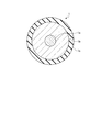
- FIG. 1 is a schematic sectional view of an optical fiber according to an embodiment.
- FIG. 2A is a schematic diagram of a step-type refractive index profile that can be used in the optical fiber according to the embodiment.
- FIG. 2B is a schematic diagram of a W-shaped refractive index profile that can be used in the optical fiber according to the embodiment.
- FIG. 2C is a schematic diagram of a trench type refractive index profile that can be used in the optical fiber according to the embodiment.
- FIG. 3 is a diagram showing an example of the relationship between the center core ⁇ and the mode field diameter or the limit fiber diameter.
- FIG. 4 is a diagram showing an example of the relationship between the effective core area and the normalized microbend loss.
- FIG. 5 is a diagram showing an example of the relationship between the primary thickness and the normalized microbend loss.
- the cutoff wavelength means ITU-T G.264.
- other terms not specifically defined in this specification are described in G. 650.1 and G.I.
- the definition and measurement method in 650.2 shall be followed.
- FIG. 1 is a schematic sectional view of an optical fiber according to an embodiment.
- the optical fiber 1 includes a core portion 1a located substantially at the center, a clad portion 1b that covers the outer periphery of the core portion 1a, and a coating portion 1c that covers the outer periphery of the clad portion 1b.
- Both the core part 1a and the clad part 1b are made of silica glass.
- the core portion 1a is made of quartz glass to which a dopant for adjusting the refractive index such as germanium (Ge) or fluorine (F) is added.
- the clad portion 1b has a refractive index lower than the maximum refractive index of the core portion 1a.
- the clad portion 1b is made of, for example, pure silica glass containing no dopant for adjusting the refractive index.
- the outer diameter (clad diameter) of the clad portion 1b is 100 ⁇ m or less, preferably less than 100 ⁇ m.
- the diameter is smaller than the cladding diameter of the single mode optical fiber conforming to the 652 standard, which is about 125 ⁇ m.
- the clad diameter is more preferably 95 ⁇ m or less from the viewpoint of reducing the diameter.
- G A single mode optical fiber compliant with the 652 standard may be referred to as a standard SMF as a standard optical fiber.
- a standard SMF usually has a resin coating portion having a thickness of about 62.5 ⁇ m on the outer periphery of the clad portion. Therefore, the outer diameter of the resin coating portion is about 250 ⁇ m.
- the optical fiber 1 has a refractive index profile as shown in FIGS. 2A, 2B, and 2C, for example.
- 2A, 2B, and 2C each show a refractive index profile in the radial direction from the central axis of the core portion 1a of the optical fiber 1.
- FIG. 2A shows a step type refractive index profile.
- profile P11 shows the refractive index profile of the core part 1a
- profile P12 shows the refractive index profile of the clad part 1b.
- the refractive index profile is indicated by the relative refractive index difference with respect to the cladding portion 1b.
- the diameter of the core portion 1a is 2a
- the relative refractive index difference of the core portion 1a with respect to the cladding portion 1b is ⁇ 1.
- FIG. 2B shows a so-called W-shaped refractive index profile.
- profile P21 shows the refractive index profile of the core part 1a
- profile P22 shows the refractive index profile of the clad part 1b.
- the core portion 1a surrounds the center core portion having a diameter of 2a and the outer periphery of the center core portion, and the refractive index is smaller than the refractive index of the clad portion and the inner diameter is 2a and the outer diameter is 2b. It consists of a depressed layer.
- the relative refractive index difference of the center core portion with respect to the clad portion 1b is ⁇ 1.
- the relative refractive index difference of the depressed layer with respect to the clad portion 1b is ⁇ 2.
- FIG. 2C shows a so-called trench type refractive index profile.
- profile P31 shows the refractive index profile of the core part 1a
- profile P32 shows the refractive index profile of the clad part 1b.
- the core portion 1a surrounds the center core portion having a diameter of 2a and the outer periphery of the center core portion, and the refractive index is smaller than the refractive index of the center core portion and the inner diameter is 2a and the outer diameter is 2b. It is composed of an intermediate layer and a trench layer surrounding the outer periphery of the intermediate layer and having a refractive index smaller than that of the cladding portion and having an inner diameter of 2b and an outer diameter of 2c.
- the relative refractive index difference of the center core portion with respect to the intermediate layer is ⁇ 1.
- the relative refractive index difference of the intermediate layer with respect to the clad portion 1b is ⁇ 2. It should be noted that ⁇ 2 is usually set to 0% or in the vicinity thereof, for example, in a range between ⁇ 0.2% and 0.2%.
- the relative refractive index difference of the trench layer with respect to the clad portion 1b is ⁇ 3.
- the coating portion 1c is made of resin, for example, and has a function of protecting the glass portion of the optical fiber 1.
- the coating portion 1c is made of, for example, a UV curable resin or the like and has a layer structure of one layer or two or more layers.
- the coating portion 1c includes a primary coating layer located on the cladding portion side and a secondary coating layer located on the outer peripheral side of the primary coating layer.
- the UV curable resin used for the coating portion 1c include urethane acrylate-based, polybutadiene acrylate-based, epoxy acrylate-based, silicone acrylate-based, polyester acrylate-based, etc. Not limited.
- the coating part 1c has a Young's modulus of about 10 to 800 MPa in the case of a one-layer structure, and 200 MPa in the present embodiment.
- the Young's modulus of the primary coating layer is about 0.2 to 1.5 MPa, which is 0.5 MPa in this embodiment.
- the Young's modulus of the secondary coating layer is about 500 to 2000 MPa, and is 1000 MPa in this embodiment.
- the thickness of the coating portion 1c is 10 ⁇ m or more, and particularly in the case of a two-layer structure, the thickness of the primary coating layer is 10 ⁇ m or more.
- the optical fiber 1 according to the present embodiment has the above-described configuration, so that the cladding portion 1b has a small diameter of 100 ⁇ m or less and the increase in microbend loss is suppressed. Therefore, the optical fiber 1 is suitable for realizing a high-density optical fiber cable.
- the following is a specific explanation.
- the present inventors have conducted the following studies in order to realize a small-diameter optical fiber in which an increase in microbend loss is suppressed.
- leakage loss is small in order to realize a small diameter optical fiber.
- the leakage loss is preferably suppressed to 0.001 dB / km or less at a wavelength of 1625 nm.
- the mode field diameter (MFD) of the small diameter optical fiber at the wavelength of 1550 nm is preferably 9 ⁇ m or more. Therefore, in the case of the three types of refractive index profiles illustrated in FIG. 2, simulation calculation was performed for various combinations of parameters related to the refractive index profile shown in FIG. 2, and the optical characteristics of the optical fiber in each combination were calculated.
- the minimum cladding diameter (limit fiber diameter) at which the leakage loss can be 0.001 dB / km or less at a wavelength of 1625 nm and the MFD at a wavelength of 1550 nm were investigated by simulation calculation. It can be said that the smaller the limit fiber diameter, the more suitable is the combination of parameters for reducing the diameter of the optical fiber.
- Table 1 shows the range of values used in the simulation calculation for the parameters ⁇ 1, ⁇ 2, ⁇ 3, b / a, c / a shown in FIG. 2a is a value within the range of 6.5 ⁇ m to 10 ⁇ m.
- FIG. 3 is a diagram showing an example of the relationship between the center core ⁇ and the MFD or the limit fiber diameter based on the above calculation result.
- the center core ⁇ means ⁇ 1.
- FIG. 3 only data whose cutoff wavelength is 1530 nm or less in the result of simulation calculation is plotted.
- the contours of the data points are omitted in the overlapping portions.
- the legend is not distinguished by the refractive index profile, it can be said that the tendency does not depend on the refractive index profile.
- the center core ⁇ ( ⁇ 1) be 0.5% or less regardless of the refractive index profile.
- the center core ⁇ is preferably 0.25% or more, and when the limit fiber diameter is 95 ⁇ m or less, the center core ⁇ is 0.3% or more.
- ⁇ 1 is preferably 0.5% or less, preferably 0.25% or more, and more preferably 0.3% or more.
- ⁇ 1 is preferably 0.25% or more from the viewpoint that the MFD of the small-diameter optical fiber at the wavelength of 1550 nm is about 10.5 ⁇ m or less to reduce the difference from the MFD of the standard SMF.
- the following optical fibers can be exemplified as the optical fibers for which the MFDs of the small-diameter optical fibers are brought close to each other to improve the compatibility. That is, G.
- An optical fiber conforming to the 657 standard (so-called bend resistant optical fiber) or the like is used. Therefore, as a characteristic of the small-diameter optical fiber, it is also preferable that the MFD at a wavelength of 1310 nm is in the range of 8.0 ⁇ m to 10.0 ⁇ m.
- the MFD at a wavelength of 1310 nm is in the range of 8.6 ⁇ m to 9.5 ⁇ m.
- the transmission loss of an optical fiber increases when the optical fiber cable is used.
- the increase amount of the transmission loss at this time is closely related to the microbend loss, and the increase amount is large when the microbend loss is large.
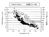
- FIG. 4 is a diagram showing an example of the relationship between standardized microbend loss and Aeff at a wavelength of 1550 nm of standard SMF and some Aeff expanded optical fibers.
- the standardized microbend loss is a value obtained by standardizing the microbend loss of a certain optical fiber with the microbend loss of the standard SMF.
- the Aeff of the standard SMF is about 80 ⁇ m 2
- the standardized microbend loss of the standard SMF itself is 1.
- the standard SMF is assumed to have a resin coating part having a two-layer structure with a thickness of about 62.5 ⁇ m on the outer periphery of the clad part.
- the normalized microbend loss is preferably 10 or less, and more preferably 5 or less. That is, the microbend loss of the small-diameter optical fiber is preferably 10 times or less that of the standard SMF, and more preferably 5 times or less.
- the microbend loss shown in FIG. 4 is measured by the fixed diameter drum method (a kind of abrasive paper method) defined by JIS C6823: 2010_10.
- the refractive index profile was set to step type, W type, or trench type, and design parameters such as ⁇ 1 in each profile were optimized by simulation calculation.
- optimization means G. 652 standard, G.I. 654 standard, or G. It means optimizing the compatibility with the optical fiber defined in the 657 standard.
- the coating portion had a two-layer structure including a primary coating layer and a secondary coating layer.
- the Young's modulus of the primary coating layer was 0.5 MPa, and the Young's modulus of the secondary coating layer was 1000 MPa.
- the thickness of the secondary coating layer was 120 ⁇ m, and the thickness of the primary coating layer was different values in the range of 5 ⁇ m to 30 ⁇ m. Then, the microbend loss of these manufactured small diameter optical fibers was measured by the fixed drum diameter method.
- FIG. 5 is a diagram showing an example of the relationship between the primary thickness and the normalized microbend loss in the above measurement.
- the primary thickness is the thickness of the primary coating layer.
- the primary thickness needs to be 10 ⁇ m or more. That is, the thickness of the coating portion needs to be 10 ⁇ m or more. If the primary thickness is 30 ⁇ m, the normalized microbend loss can be set to about 1, so the primary thickness may be 30 ⁇ m or less. It was also confirmed that there is not much correlation between the thickness of the secondary coating layer and the normalized microbend loss, and the primary thickness is important.
- the step type, the W type, and the trench type are exemplified as the refractive index profile, but other refractive index profiles such as the segment core type and the W + side core type can also be applied.
- the present invention is not limited to the above embodiment.
- the present invention also includes those configured by appropriately combining the above-described components. Further, further effects and modified examples can be easily derived by those skilled in the art. Therefore, the broader aspects of the present invention are not limited to the above embodiments, and various modifications can be made.
- optical fiber according to the present invention can be suitably used in the field of optical communication such as datacom and telecom.
- Optical fiber 1a Core part 1b Cladding part 1c Coating part P11, P12, P21, P22, P31, P32 Profile
Abstract
The purpose of the present invention is to obtain an optical fiber which has a small diameter and in which an increase in microbending loss is suppressed. The optical fiber comprises: a core part that is made of silica-based glass; a cladding part that covers the outer periphery of the core part and is made of silica-based glass having a refractive index lower than the maximum refractive index of the core part; and a coating part that covers the outer periphery of the cladding part, wherein the outer diameter of the cladding part is 100 μm or less, the relative refractive index difference Δ1 of the core part is 0.5 % or less, and the thickness of the coating part is 10 μm or more.
Description
本発明は、光ファイバに関する。
The present invention relates to an optical fiber.
データコムやテレコムの分野において、高密度光ファイバケーブルを実現する光ファイバとして、細径の光ファイバが注目されている。ここで、細径光ファイバとは、主に光ファイバのガラスからなる部分を細径化したものであり、クラッド径が細径のものである。ただし、クラッド径が細径化されたことによって、クラッド部の外周を覆うように形成されたコーティング部を含む外径が細径化されたものも細径光ファイバに含まれる。
In the fields of datacom and telecom, small-diameter optical fibers are drawing attention as optical fibers that realize high-density optical fiber cables. Here, the small-diameter optical fiber is an optical fiber in which a portion mainly made of glass has a small diameter, and has a small clad diameter. However, a thin optical fiber includes a thin outer diameter including a coating portion formed so as to cover the outer periphery of the cladding portion due to the thinning of the cladding diameter.
従来、細径の光ファイバとして、クラッド部に対するコア部の比屈折率差を高くした構成が開示されている(非特許文献1)。非特許文献1の光ファイバは、比屈折率差を高くしているので、その特性が、ITU-T(国際電気通信連合)G.652で定義される標準的なシングルモード光ファイバの規格(以下、G.652規格)に準拠するものではない。また、細径の光ファイバとして、比屈折率差が-0.08%以上のトレンチ層を設けた構成が開示されている(特許文献1)。特許文献1の光ファイバは、G.652規格に準拠するものであり、そのクラッド径(ファイバ径)は100μm~125μm程度である。また、細径の光ファイバとして、プライマリコート層とセカンダリコート層とをコーティング部として有し、セカンダリコーティング層を25μm以下にした構成が開示されている(特許文献2)。特許文献2の光ファイバは、ファイバ径は125μmであるが、コーティング厚を小さくすることによって細径化を実現している。
Conventionally, as a small-diameter optical fiber, a configuration has been disclosed in which the relative refractive index difference between the core portion and the cladding portion is increased (Non-Patent Document 1). Since the optical fiber of Non-Patent Document 1 has a high relative refractive index difference, its characteristics are ITU-T (International Telecommunication Union) G.264. It does not comply with the standard of a standard single-mode optical fiber (hereinafter, referred to as G.652 standard) defined by 652. Further, as a small-diameter optical fiber, a configuration is disclosed in which a trench layer having a relative refractive index difference of −0.08% or more is provided (Patent Document 1). The optical fiber of Patent Document 1 is G. It complies with the 652 standard, and its cladding diameter (fiber diameter) is about 100 μm to 125 μm. Further, as a small-diameter optical fiber, a configuration is disclosed in which a primary coat layer and a secondary coat layer are provided as coating portions, and the secondary coating layer is 25 μm or less (Patent Document 2). The optical fiber of Patent Document 2 has a fiber diameter of 125 μm, but the diameter is reduced by reducing the coating thickness.
また、特許文献3には、有効コア断面積(Aeff)が130μm2以上と比較的大きい光ファイバにて、マイクロベンド損失を抑制する構成が開示されている。特許文献3の光ファイバは、プライマリコーティング層の外径が185μm以上220μm以下であり、セカンダリコーティング層の外径が225μm以上260μm以下である。
Further, Patent Document 3 discloses a configuration for suppressing microbend loss in an optical fiber having a relatively large effective core area (Aeff) of 130 μm 2 or more. In the optical fiber of Patent Document 3, the primary coating layer has an outer diameter of 185 μm or more and 220 μm or less, and the secondary coating layer has an outer diameter of 225 μm or more and 260 μm or less.
ここで、石英系ガラスからなる光ファイバにおいて、クラッド径を細径化、たとえば100μm以下にした場合には、その細径化が光ファイバのマイクロベンド損失に影響を及ぼし、マイクロベンド損失が増加すると考えられる。特に、マイクロベンド損失の増加は、最も実用化されている光ファイバである、G.652規格に準拠する特性、またはそれに近い特性を有する光ファイバにおいて重要である。
Here, in an optical fiber made of silica-based glass, when the cladding diameter is reduced, for example, 100 μm or less, the reduction in diameter affects the microbend loss of the optical fiber, and the microbend loss increases. Conceivable. In particular, the increase in microbend loss is due to G.G. This is important in an optical fiber having a characteristic conforming to the 652 standard or a characteristic close thereto.
本発明は、上記に鑑みてなされたものであって、その目的は、細径であるとともにマイクロベンド損失の増加が抑制された光ファイバを提供することにある。
The present invention has been made in view of the above, and an object thereof is to provide an optical fiber having a small diameter and suppressing an increase in microbend loss.
上述した課題を解決し、目的を達成するために、本発明の一態様に係る光ファイバは、石英系ガラスからなるコア部と、前記コア部の外周を覆い、前記コア部の最大屈折率よりも低い屈折率を有する石英系ガラスからなるクラッド部と、前記クラッド部の外周を覆うコーティング部と、を備え、前記クラッド部の外径は100μm以下であり、前記コア部の比屈折率差Δ1は0.5%以下であり、前記コーティング部の厚さは10μm以上であることを特徴とする。
In order to solve the above-mentioned problems and achieve the object, an optical fiber according to an aspect of the present invention, a core portion made of silica-based glass, covers the outer periphery of the core portion, from the maximum refractive index of the core portion. A cladding part made of silica-based glass having a low refractive index, and a coating part covering the outer periphery of the cladding part. The cladding part has an outer diameter of 100 μm or less, and the relative refractive index difference Δ1 of the core part is Is 0.5% or less, and the thickness of the coating portion is 10 μm or more.
本発明の一態様に係る光ファイバは、前記コーティング部は、前記クラッド部側に位置するプライマリコーティング層と、前記プライマリコーティング層の外周側に位置するセカンダリコーティング層とを有し、前記プライマリコーティング層の厚さが10μm以上であることを特徴とする。
In the optical fiber according to an aspect of the present invention, the coating portion has a primary coating layer located on the cladding portion side and a secondary coating layer located on the outer peripheral side of the primary coating layer, and the primary coating layer Is 10 μm or more in thickness.
本発明の一態様に係る光ファイバは、前記プライマリコーティング層の厚さが30μm以下であることを特徴とする。
The optical fiber according to one aspect of the present invention is characterized in that the thickness of the primary coating layer is 30 μm or less.
本発明の一態様に係る光ファイバは、前記クラッド部の外径が95μm以下であることを特徴とする。
The optical fiber according to one aspect of the present invention is characterized in that the outer diameter of the clad portion is 95 μm or less.
本発明の一態様に係る光ファイバは、波長1550nmにおけるマイクロベンド損失が、ITU-T G.652で定義される規格に準拠する特性を有しかつクラッド部の外周に厚さが62.5μmの樹脂コーティング部を有する標準光ファイバの波長1550nmにおけるマイクロベンド損失の10倍以下であることを特徴とする。
The optical fiber according to one aspect of the present invention has a microbend loss at a wavelength of 1550 nm that is ITU-T. It is 10 times or less than the microbend loss at a wavelength of 1550 nm of a standard optical fiber having a characteristic conforming to the standard defined by 652 and having a resin coating portion having a thickness of 62.5 μm on the outer circumference of a clad portion. And
本発明の一態様に係る光ファイバは、前記マイクロベンド損失は、研磨紙法にて測定した値であることを特徴とする。
The optical fiber according to one aspect of the present invention is characterized in that the microbend loss is a value measured by a polishing paper method.
本発明の一態様に係る光ファイバは、ステップ型の屈折率プロファイルを有することを特徴とする。
The optical fiber according to one aspect of the present invention is characterized by having a step type refractive index profile.
本発明の一態様に係る光ファイバは、W型の屈折率プロファイルを有することを特徴とする。
The optical fiber according to one aspect of the present invention is characterized by having a W-shaped refractive index profile.
本発明の一態様に係る光ファイバは、トレンチ型の屈折率プロファイルを有することを特徴とする。
The optical fiber according to one aspect of the present invention is characterized by having a trench type refractive index profile.
本発明の一態様に係る光ファイバは、波長1310nmにおけるモードフィールド径が8.0μmから10.0μmまでの範囲内であることを特徴とする。
The optical fiber according to one aspect of the present invention is characterized in that the mode field diameter at a wavelength of 1310 nm is in the range of 8.0 μm to 10.0 μm.
本発明の一態様に係る光ファイバは、波長1550nmにおけるモードフィールド径が9μm以上であることを特徴とする。
The optical fiber according to one aspect of the present invention is characterized in that the mode field diameter at a wavelength of 1550 nm is 9 μm or more.
本発明の一態様に係る光ファイバは、前記コア部の比屈折率差Δ1が0.25%以上であることを特徴とする。
The optical fiber according to one aspect of the present invention is characterized in that the relative refractive index difference Δ1 of the core portion is 0.25% or more.
本発明によれは、細径であるとともにマイクロベンド損失の増加が抑制された光ファイバを実現できるという効果を奏する。
According to the present invention, it is possible to realize an optical fiber having a small diameter and suppressing an increase in microbend loss.
以下に、図面を参照しながら、本発明の実施形態を詳細に説明する。なお、以下に説明する実施形態により本発明が限定されるものではない。また、各図面において、同一または対応する構成要素には適宜同一の符号を付している。また、本明細書においては、カットオフ波長とは、ITU-T G.650.1で定義するケーブルカットオフ波長をいう。また、その他、本明細書で特に定義しない用語についてはG.650.1およびG.650.2における定義、測定方法に従うものとする。
Hereinafter, embodiments of the present invention will be described in detail with reference to the drawings. The present invention is not limited to the embodiments described below. Moreover, in each drawing, the same or corresponding components are designated by the same reference numerals. In addition, in the present specification, the cutoff wavelength means ITU-T G.264. A cable cutoff wavelength defined by 650.1. Further, other terms not specifically defined in this specification are described in G. 650.1 and G.I. The definition and measurement method in 650.2 shall be followed.
(実施形態)
図1は、実施形態に係る光ファイバの模式的な断面図である。光ファイバ1は、略中心に位置するコア部1aと、コア部1aの外周を覆うクラッド部1bと、クラッド部1bの外周を覆うコーティング部1cとを備えている。 (Embodiment)
FIG. 1 is a schematic sectional view of an optical fiber according to an embodiment. Theoptical fiber 1 includes a core portion 1a located substantially at the center, a clad portion 1b that covers the outer periphery of the core portion 1a, and a coating portion 1c that covers the outer periphery of the clad portion 1b.
図1は、実施形態に係る光ファイバの模式的な断面図である。光ファイバ1は、略中心に位置するコア部1aと、コア部1aの外周を覆うクラッド部1bと、クラッド部1bの外周を覆うコーティング部1cとを備えている。 (Embodiment)
FIG. 1 is a schematic sectional view of an optical fiber according to an embodiment. The
コア部1aとクラッド部1bとは、いずれも石英系ガラスからなる。たとえば、コア部1aは、ゲルマニウム(Ge)やフッ素(F)などの屈折率調整用のドーパントが添加された石英ガラスからなる。クラッド部1bは、コア部1aの最大屈折率よりも低い屈折率を有する。クラッド部1bは、たとえば屈折率調整用のドーパントを含まない純石英ガラスからなる。
Both the core part 1a and the clad part 1b are made of silica glass. For example, the core portion 1a is made of quartz glass to which a dopant for adjusting the refractive index such as germanium (Ge) or fluorine (F) is added. The clad portion 1b has a refractive index lower than the maximum refractive index of the core portion 1a. The clad portion 1b is made of, for example, pure silica glass containing no dopant for adjusting the refractive index.
クラッド部1bの外径(クラッド径)は、100μm以下、好ましくは100μm未満であり、G.652規格に準拠するシングルモード光ファイバのクラッド径である約125μmよりも細径化されている。なお、クラッド径は95μm以下であることが細径化の観点からはより好ましい。以下、G.652規格に準拠するシングルモード光ファイバを標準光ファイバとして標準SMFと記載する場合がある。このような標準SMFは、通常はクラッド部の外周に厚さが約62.5μmの樹脂コーティング部を有している。したがって、樹脂コーティング部の外径は約250μmとなる。
The outer diameter (clad diameter) of the clad portion 1b is 100 μm or less, preferably less than 100 μm. The diameter is smaller than the cladding diameter of the single mode optical fiber conforming to the 652 standard, which is about 125 μm. The clad diameter is more preferably 95 μm or less from the viewpoint of reducing the diameter. Hereinafter, G. A single mode optical fiber compliant with the 652 standard may be referred to as a standard SMF as a standard optical fiber. Such a standard SMF usually has a resin coating portion having a thickness of about 62.5 μm on the outer periphery of the clad portion. Therefore, the outer diameter of the resin coating portion is about 250 μm.
光ファイバ1は、たとえば図2A、図2B、および図2Cに示すような屈折率プロファイルを有する。図2A、図2B、および図2Cはいずれも、光ファイバ1のコア部1aの中心軸から半径方向における屈折率プロファイルを示している。
The optical fiber 1 has a refractive index profile as shown in FIGS. 2A, 2B, and 2C, for example. 2A, 2B, and 2C each show a refractive index profile in the radial direction from the central axis of the core portion 1a of the optical fiber 1.
図2Aは、ステップ型の屈折率プロファイルを示している。図2Aにおいて、プロファイルP11がコア部1aの屈折率プロファイルを示し、プロファイルP12がクラッド部1bの屈折率プロファイルを示す。なお、屈折率プロファイルは、クラッド部1bに対する比屈折率差で示している。ステップ型の屈折率プロファイルでは、コア部1aの直径(コア径)は2aであり、クラッド部1bに対するコア部1aの比屈折率差はΔ1である。
FIG. 2A shows a step type refractive index profile. In FIG. 2A, profile P11 shows the refractive index profile of the core part 1a, and profile P12 shows the refractive index profile of the clad part 1b. The refractive index profile is indicated by the relative refractive index difference with respect to the cladding portion 1b. In the step type refractive index profile, the diameter of the core portion 1a (core diameter) is 2a, and the relative refractive index difference of the core portion 1a with respect to the cladding portion 1b is Δ1.
図2Bは、いわゆるW型の屈折率プロファイルを示している。図2Bにおいて、プロファイルP21がコア部1aの屈折率プロファイルを示し、プロファイルP22がクラッド部1bの屈折率プロファイルを示す。W型の屈折率プロファイルでは、コア部1aは、直径が2aのセンタコア部と、センタコア部の外周を囲んでおり、屈折率がクラッド部の屈折率よりも小さく内径が2aで外径が2bのディプレスト層とで構成されている。クラッド部1bに対するセンタコア部の比屈折率差はΔ1である。クラッド部1bに対するディプレスト層の比屈折率差はΔ2である。
FIG. 2B shows a so-called W-shaped refractive index profile. In FIG. 2B, profile P21 shows the refractive index profile of the core part 1a, and profile P22 shows the refractive index profile of the clad part 1b. In the W-shaped refractive index profile, the core portion 1a surrounds the center core portion having a diameter of 2a and the outer periphery of the center core portion, and the refractive index is smaller than the refractive index of the clad portion and the inner diameter is 2a and the outer diameter is 2b. It consists of a depressed layer. The relative refractive index difference of the center core portion with respect to the clad portion 1b is Δ1. The relative refractive index difference of the depressed layer with respect to the clad portion 1b is Δ2.
図2Cは、いわゆるトレンチ型の屈折率プロファイルを示している。図2Cにおいて、プロファイルP31がコア部1aの屈折率プロファイルを示し、プロファイルP32がクラッド部1bの屈折率プロファイルを示す。トレンチ型の屈折率プロファイルでは、コア部1aは、直径が2aのセンタコア部と、センタコア部の外周を囲んでおり、屈折率がセンタコア部の屈折率よりも小さく内径が2aで外径が2bの中間層と、中間層の外周を囲んでおり、屈折率がクラッド部の屈折率よりも小さく内径が2bで外径が2cのトレンチ層とで構成されている。中間層に対するセンタコア部の比屈折率差はΔ1である。クラッド部1bに対する中間層の比屈折率差はΔ2である。なお、Δ2は、通常は0%またはその近傍、たとえば-0.2%~0.2%の間の範囲に設定される。クラッド部1bに対するトレンチ層の比屈折率差はΔ3である。
FIG. 2C shows a so-called trench type refractive index profile. In FIG. 2C, profile P31 shows the refractive index profile of the core part 1a, and profile P32 shows the refractive index profile of the clad part 1b. In the trench type refractive index profile, the core portion 1a surrounds the center core portion having a diameter of 2a and the outer periphery of the center core portion, and the refractive index is smaller than the refractive index of the center core portion and the inner diameter is 2a and the outer diameter is 2b. It is composed of an intermediate layer and a trench layer surrounding the outer periphery of the intermediate layer and having a refractive index smaller than that of the cladding portion and having an inner diameter of 2b and an outer diameter of 2c. The relative refractive index difference of the center core portion with respect to the intermediate layer is Δ1. The relative refractive index difference of the intermediate layer with respect to the clad portion 1b is Δ2. It should be noted that Δ2 is usually set to 0% or in the vicinity thereof, for example, in a range between −0.2% and 0.2%. The relative refractive index difference of the trench layer with respect to the clad portion 1b is Δ3.
図1に戻って、コーティング部1cは、たとえば樹脂からなり、光ファイバ1のガラス部分を保護する機能を有する。コーティング部1cは、たとえばUV硬化樹脂等からなり、1層または2層以上の層構造を有する。コーティング部1cが2層構造の場合、コーティング部1cは、クラッド部側に位置するプライマリコーティング層と、プライマリコーティング層の外周側に位置するセカンダリコーティング層とからなる。コーティング部1cに用いられるUV硬化樹脂としては、たとえばウレタンアクリレート系、ポリブタジエンアクリレート系、エポキシアクリレート系、シリコーンアクリレート系、ポリエステルアクリレート系などがあるが、光ファイバのコーティングに使用されるものであれば特に限定されない。
Returning to FIG. 1, the coating portion 1c is made of resin, for example, and has a function of protecting the glass portion of the optical fiber 1. The coating portion 1c is made of, for example, a UV curable resin or the like and has a layer structure of one layer or two or more layers. When the coating portion 1c has a two-layer structure, the coating portion 1c includes a primary coating layer located on the cladding portion side and a secondary coating layer located on the outer peripheral side of the primary coating layer. Examples of the UV curable resin used for the coating portion 1c include urethane acrylate-based, polybutadiene acrylate-based, epoxy acrylate-based, silicone acrylate-based, polyester acrylate-based, etc. Not limited.
コーティング部1cは、1層構造の場合は、ヤング率が10~800MPaの程度であり、本実施形態では200MPaである。一方、コーティング部1cが2層構造の場合は、プライマリコーティング層のヤング率は0.2~1.5MPaの程度であり、本実施形態では0.5MPaである。セカンダリコーティング層のヤング率は500~2000MPaの程度であり、本実施形態では1000MPaである。
The coating part 1c has a Young's modulus of about 10 to 800 MPa in the case of a one-layer structure, and 200 MPa in the present embodiment. On the other hand, when the coating portion 1c has a two-layer structure, the Young's modulus of the primary coating layer is about 0.2 to 1.5 MPa, which is 0.5 MPa in this embodiment. The Young's modulus of the secondary coating layer is about 500 to 2000 MPa, and is 1000 MPa in this embodiment.
コーティング部1cの厚さは10μm以上であり、特に2層構造の場合はプライマリコーティング層の厚さが10μm以上である。
The thickness of the coating portion 1c is 10 μm or more, and particularly in the case of a two-layer structure, the thickness of the primary coating layer is 10 μm or more.
本実施形態に係る光ファイバ1は、上記構成を備えることによって、クラッド部1bが100μm以下と細径であるとともに、マイクロベンド損失の増加が抑制されたものとなる。したがって、光ファイバ1は、高密度光ファイバケーブルの実現に好適なものである。
The optical fiber 1 according to the present embodiment has the above-described configuration, so that the cladding portion 1b has a small diameter of 100 μm or less and the increase in microbend loss is suppressed. Therefore, the optical fiber 1 is suitable for realizing a high-density optical fiber cable.
以下、具体的に説明する。本発明者らは、マイクロベンド損失の増加が抑制された細径光ファイバを実現するために、以下のような検討を行った。
The following is a specific explanation. The present inventors have conducted the following studies in order to realize a small-diameter optical fiber in which an increase in microbend loss is suppressed.
まず、細径光ファイバを実現するためには、リーケージ損失(漏れ損失)が小さいことが重要である。リーケージ損失は、たとえば波長1625nmにて0.001dB/km以下に抑制されていることが好ましい。また、細径光ファイバを標準SMFと光接続した際に接続損失を抑制するためには、細径光ファイバの波長1550nmにおけるモードフィールド径(MFD)が9μm以上であることが好ましい。そこで、図2に例示する3種の屈折率プロファイルの場合に、図2に示す屈折率プロファイルに関するパラメータの様々な組み合わせに対してシミュレーション計算を行ない、各組み合わせにおける光ファイバの光学特性を算出した。そして、リーケージ損失が波長1625nmにて0.001dB/km以下とできる最小のクラッド径(限界ファイバ径)と、波長1550nmにおけるMFDとを、シミュレーション計算によって調査した。なお、限界ファイバ径が小さい程、光ファイバの細径化に適したパラメータの組み合わせといえる。
First of all, it is important that leakage loss (leakage loss) is small in order to realize a small diameter optical fiber. The leakage loss is preferably suppressed to 0.001 dB / km or less at a wavelength of 1625 nm. Further, in order to suppress the connection loss when the small diameter optical fiber is optically connected to the standard SMF, the mode field diameter (MFD) of the small diameter optical fiber at the wavelength of 1550 nm is preferably 9 μm or more. Therefore, in the case of the three types of refractive index profiles illustrated in FIG. 2, simulation calculation was performed for various combinations of parameters related to the refractive index profile shown in FIG. 2, and the optical characteristics of the optical fiber in each combination were calculated. Then, the minimum cladding diameter (limit fiber diameter) at which the leakage loss can be 0.001 dB / km or less at a wavelength of 1625 nm and the MFD at a wavelength of 1550 nm were investigated by simulation calculation. It can be said that the smaller the limit fiber diameter, the more suitable is the combination of parameters for reducing the diameter of the optical fiber.
表1は、図2に示したパラメータであるΔ1、Δ2、Δ3、b/a、c/aについて、シミュレーション計算に用いた値の範囲を示している。なお、2aは、6.5μmから10μmまでの範囲内の値とした。
Table 1 shows the range of values used in the simulation calculation for the parameters Δ1, Δ2, Δ3, b / a, c / a shown in FIG. 2a is a value within the range of 6.5 μm to 10 μm.

図3は、上記計算結果に基づく、センタコアΔと、MFDまたは限界ファイバ径との関係の一例を示す図である。ここで、センタコアΔはΔ1を意味する。また、図3では、シミュレーション計算の結果においてカットオフ波長が1530nm以下であったデータのみをプロットしている。また、図3では、白四角または黒菱形の凡例で示したデータ点について、データ点の輪郭が重なっている部分では輪郭の図示を省略している。また、図3では、屈折率プロファイルによって凡例を区別していないので、屈折率プロファイルによらない傾向を示しているといえる。
FIG. 3 is a diagram showing an example of the relationship between the center core Δ and the MFD or the limit fiber diameter based on the above calculation result. Here, the center core Δ means Δ1. Further, in FIG. 3, only data whose cutoff wavelength is 1530 nm or less in the result of simulation calculation is plotted. In addition, in FIG. 3, regarding the data points indicated by the legend of white squares or black rhombuses, the contours of the data points are omitted in the overlapping portions. Further, in FIG. 3, since the legend is not distinguished by the refractive index profile, it can be said that the tendency does not depend on the refractive index profile.
図3から明らかなように、波長1550nmにおけるMFDを9μm以上にする場合には、屈折率プロファイルによらず、センタコアΔ(Δ1)を0.5%以下にすることが好ましい。また、限界ファイバ径を100μm以下にする場合には、センタコアΔを0.25%以上にすることが好ましく、限界ファイバ径を95μm以下にする場合には、センタコアΔを0.3%以上にすることが好ましい。したがって、Δ1は0.5%以下が好ましく、0.25%以上が好ましく、0.3%以上がより好ましい。なお、細径光ファイバの波長1550nmにおけるMFDを10.5μm以下程度とし、標準SMFのMFDとの差を小さくする観点からも、Δ1は0.25%以上が好ましい。このように2つ光ファイバのMFDの差を小さくすることによって、2つ光ファイバの接続特性等の適合性が確保される。
As is apparent from FIG. 3, when the MFD at a wavelength of 1550 nm is 9 μm or more, it is preferable that the center core Δ (Δ1) be 0.5% or less regardless of the refractive index profile. When the limit fiber diameter is 100 μm or less, the center core Δ is preferably 0.25% or more, and when the limit fiber diameter is 95 μm or less, the center core Δ is 0.3% or more. Preferably. Therefore, Δ1 is preferably 0.5% or less, preferably 0.25% or more, and more preferably 0.3% or more. Note that Δ1 is preferably 0.25% or more from the viewpoint that the MFD of the small-diameter optical fiber at the wavelength of 1550 nm is about 10.5 μm or less to reduce the difference from the MFD of the standard SMF. By reducing the difference in MFD between the two optical fibers in this manner, compatibility such as connection characteristics between the two optical fibers is ensured.
なお、細径光ファイバのMFDを近づけ、適合性を高くする対象の光ファイバとしては、標準SMFの他に、たとえば以下の光ファイバが例示できる。すなわち、ITU-TのG.654規格に準拠する光ファイバ(いわゆるカットオフシフト光ファイバ)やG.657規格に準拠する光ファイバ(いわゆる曲げ耐性光ファイバ)などである。したがって、細径光ファイバの特性としては、波長1310nmにおけるMFDが8.0μmから10.0μmまでの範囲内であることも好ましい。なお、G.652規格では、波長1310nmにおけるMFDは8.6μmから9.5μmまでの範囲内である。
In addition to the standard SMF, for example, the following optical fibers can be exemplified as the optical fibers for which the MFDs of the small-diameter optical fibers are brought close to each other to improve the compatibility. That is, G. An optical fiber conforming to the 654 standard (so-called cut-off shift optical fiber) or G. An optical fiber conforming to the 657 standard (so-called bend resistant optical fiber) or the like is used. Therefore, as a characteristic of the small-diameter optical fiber, it is also preferable that the MFD at a wavelength of 1310 nm is in the range of 8.0 μm to 10.0 μm. G. According to the 652 standard, the MFD at a wavelength of 1310 nm is in the range of 8.6 μm to 9.5 μm.
つづいて、マイクロベンド損失の検討結果について説明する。通常、光ファイバの伝送損失は、光ファイバケーブルとされた状態では増加する。このときの伝送損失の増加量はマイクロベンド損失と密接な関係があり、マイクロベンド損失が大きいと増加量も大きい。
Next, I will explain the examination results of microbend loss. Usually, the transmission loss of an optical fiber increases when the optical fiber cable is used. The increase amount of the transmission loss at this time is closely related to the microbend loss, and the increase amount is large when the microbend loss is large.
細径光ファイバのマクロベンド損失を検討する上で、まず、現在、海底光ケーブルなどの用途で実用化されている、Aeffが大きい光ファイバ(Aeff拡大光ファイバとも呼ばれる)におけるマイクロベンド損失の程度を検討した。
In considering the macrobend loss of a small-diameter optical fiber, first, the degree of microbend loss in an optical fiber with a large Aeff (also called an Aeff expanded optical fiber), which is currently put into practical use in applications such as submarine optical cables, is described. investigated.
図4は、標準SMFおよび幾つかのAeff拡大光ファイバの波長1550nmにおけるAeffと、規格化マイクロベンド損失との関係の一例を示す図である。ここで、規格化マイクロベンド損失とは、或る光ファイバのマイクロベンド損失を、標準SMFのマイクロベンド損失で規格化した値である。なお、標準SMFのAeffは約80μm2であり、標準SMF自身の規格化マイクロベンド損失は1である。なお、標準SMFは、クラッド部の外周に厚さが約62.5μmの2層構造の樹脂コーティング部を有しているものとする。
FIG. 4 is a diagram showing an example of the relationship between standardized microbend loss and Aeff at a wavelength of 1550 nm of standard SMF and some Aeff expanded optical fibers. Here, the standardized microbend loss is a value obtained by standardizing the microbend loss of a certain optical fiber with the microbend loss of the standard SMF. The Aeff of the standard SMF is about 80 μm 2, and the standardized microbend loss of the standard SMF itself is 1. The standard SMF is assumed to have a resin coating part having a two-layer structure with a thickness of about 62.5 μm on the outer periphery of the clad part.
細径光ファイバのマイクロベンド損失についても、実用化されている、Aeffが150μm2程度までのAeff拡大光ファイバのマイクロベンド損失程度に抑制することが、実用上好ましい。したがって、図4からわかるように、規格化マイクロベンド損失は10以下が好ましく、5以下がより好ましい。すなわち、細径光ファイバのマイクロベンド損失は、標準SMFの10倍以下が好ましく、5倍以下がより好ましい。なお、図4に示すマイクロベンド損失は、JIS C6823:2010_10で規定された固定径ドラム法(研磨紙法の一種)で測定されたものである。
Regarding the microbend loss of the small-diameter optical fiber, it is practically preferable to suppress it to the microbend loss of the Aeff expanded optical fiber having an Aeff of up to about 150 μm 2, which has been put to practical use. Therefore, as can be seen from FIG. 4, the normalized microbend loss is preferably 10 or less, and more preferably 5 or less. That is, the microbend loss of the small-diameter optical fiber is preferably 10 times or less that of the standard SMF, and more preferably 5 times or less. The microbend loss shown in FIG. 4 is measured by the fixed diameter drum method (a kind of abrasive paper method) defined by JIS C6823: 2010_10.
以上の検討結果をもとに、屈折率プロファイルをステップ型、W型、またはトレンチ型に設定して、各プロファイルにおけるΔ1等の設計パラメータをシミュレーション計算にて最適化した。ここで、最適化とは、G.652規格、G.654規格、またはG.657規格で規定される光ファイバに対する適合性を最適化することを意味する。このシミュレーション計算結果に基づき、クラッド径を75μmから100μmまでの範囲の異なる値とした複数の細径光ファイバを作製した。なお、コーティング部については、プライマリコーティング層とセカンダリコーティング層との2層構造とした。プライマリコーティング層のヤング率は0.5MPaとし、セカンダリコーティング層のヤング率は1000MPaとした。セカンダリコーティング層の厚さは120μmとし、プライマリコーティング層の厚さは5μmから30μmまでの範囲の異なる値とした。そして、作製したこれらの細径光ファイバのマイクロベンド損失を、固定ドラム径法にて測定した。
Based on the above examination results, the refractive index profile was set to step type, W type, or trench type, and design parameters such as Δ1 in each profile were optimized by simulation calculation. Here, optimization means G. 652 standard, G.I. 654 standard, or G. It means optimizing the compatibility with the optical fiber defined in the 657 standard. Based on the results of this simulation calculation, a plurality of small-diameter optical fibers having different cladding diameters ranging from 75 μm to 100 μm were manufactured. The coating portion had a two-layer structure including a primary coating layer and a secondary coating layer. The Young's modulus of the primary coating layer was 0.5 MPa, and the Young's modulus of the secondary coating layer was 1000 MPa. The thickness of the secondary coating layer was 120 μm, and the thickness of the primary coating layer was different values in the range of 5 μm to 30 μm. Then, the microbend loss of these manufactured small diameter optical fibers was measured by the fixed drum diameter method.
図5は、上記測定におけるプライマリ厚と規格化マイクロベンド損失との関係の一例を示す図である。ここで、プライマリ厚とはプライマリコーティング層の厚さである。図5に示すように、規格化マイクロベンド損失を10以下にするには、プライマリ厚を10μm以上とする必要がある。つまり、コーティング部の厚さは10μm以上とする必要がある。また、プライマリ厚が30μmであれば、規格化マイクロベンド損失を1程度とできるので、プライマリ厚は30μm以下でもよい。また、セカンダリコーティング層の厚さと規格化マイクロベンド損失との間にはあまり相関がなく、プライマリ厚が重要であることも確認された。
FIG. 5 is a diagram showing an example of the relationship between the primary thickness and the normalized microbend loss in the above measurement. Here, the primary thickness is the thickness of the primary coating layer. As shown in FIG. 5, in order to reduce the normalized microbend loss to 10 or less, the primary thickness needs to be 10 μm or more. That is, the thickness of the coating portion needs to be 10 μm or more. If the primary thickness is 30 μm, the normalized microbend loss can be set to about 1, so the primary thickness may be 30 μm or less. It was also confirmed that there is not much correlation between the thickness of the secondary coating layer and the normalized microbend loss, and the primary thickness is important.
なお、上記実施形態では、屈折率プロファイルとしてステップ型、W型、トレンチ型を例示しているが、セグメントコア型やW+サイドコア型などのその他の屈折率プロファイルについても適用できる。
In the above embodiment, the step type, the W type, and the trench type are exemplified as the refractive index profile, but other refractive index profiles such as the segment core type and the W + side core type can also be applied.
また、上記実施形態により本発明が限定されるものではない。上述した各構成要素を適宜組み合わせて構成したものも本発明に含まれる。また、さらなる効果や変形例は、当業者によって容易に導き出すことができる。よって、本発明のより広範な態様は、上記の実施形態に限定されるものではなく、様々な変更が可能である。
Further, the present invention is not limited to the above embodiment. The present invention also includes those configured by appropriately combining the above-described components. Further, further effects and modified examples can be easily derived by those skilled in the art. Therefore, the broader aspects of the present invention are not limited to the above embodiments, and various modifications can be made.
本発明に係る光ファイバは、データコムやテレコムなどの光通信分野に好適に利用できる。
The optical fiber according to the present invention can be suitably used in the field of optical communication such as datacom and telecom.
1 光ファイバ
1a コア部
1b クラッド部
1c コーティング部
P11、P12、P21、P22、P31、P32 プロファイル 1Optical fiber 1a Core part 1b Cladding part 1c Coating part P11, P12, P21, P22, P31, P32 Profile
1a コア部
1b クラッド部
1c コーティング部
P11、P12、P21、P22、P31、P32 プロファイル 1
Claims (12)
- 石英系ガラスからなるコア部と、
前記コア部の外周を覆い、前記コア部の最大屈折率よりも低い屈折率を有する石英系ガラスからなるクラッド部と、
前記クラッド部の外周を覆うコーティング部と、
を備え、
前記クラッド部の外径は100μm以下であり、
前記コア部の比屈折率差Δ1は0.5%以下であり、
前記コーティング部の厚さは10μm以上であることを特徴とする光ファイバ。 A core made of quartz glass,
Covering the outer periphery of the core portion, a cladding portion made of silica-based glass having a refractive index lower than the maximum refractive index of the core portion,
A coating portion that covers the outer periphery of the clad portion,
Equipped with
The outer diameter of the clad portion is 100 μm or less,
The relative refractive index difference Δ1 of the core portion is 0.5% or less,
The optical fiber, wherein the coating portion has a thickness of 10 μm or more. - 前記コーティング部は、前記クラッド部側に位置するプライマリコーティング層と、前記プライマリコーティング層の外周側に位置するセカンダリコーティング層とを有し、前記プライマリコーティング層の厚さが10μm以上であることを特徴とする請求項1に記載の光ファイバ。 The coating part has a primary coating layer located on the cladding part side and a secondary coating layer located on the outer peripheral side of the primary coating layer, and the thickness of the primary coating layer is 10 μm or more. The optical fiber according to claim 1.
- 前記プライマリコーティング層の厚さが30μm以下であることを特徴とする請求項2に記載の光ファイバ。 The optical fiber according to claim 2, wherein the thickness of the primary coating layer is 30 μm or less.
- 前記クラッド部の外径が95μm以下であることを特徴とする請求項1~3のいずれか一つに記載の光ファイバ。 The optical fiber according to any one of claims 1 to 3, wherein the outer diameter of the clad portion is 95 µm or less.
- 波長1550nmにおけるマイクロベンド損失が、ITU-T G.652で定義される規格に準拠する特性を有しかつクラッド部の外周に厚さが62.5μmの樹脂コーティング部を有する標準光ファイバの波長1550nmにおけるマイクロベンド損失の10倍以下であることを特徴とする請求項1~4のいずれか一つに記載の光ファイバ。 The microbend loss at the wavelength of 1550 nm is ITU-T G. It is 10 times or less than the microbend loss at a wavelength of 1550 nm of a standard optical fiber having a characteristic conforming to the standard defined by 652 and having a resin coating portion having a thickness of 62.5 μm on the outer circumference of a clad portion. The optical fiber according to any one of claims 1 to 4.
- 前記マイクロベンド損失は、研磨紙法にて測定した値であることを特徴とする請求項5に記載の光ファイバ。 The optical fiber according to claim 5, wherein the microbend loss is a value measured by a polishing paper method.
- ステップ型の屈折率プロファイルを有することを特徴とする請求項1~6のいずれか一つに記載の光ファイバ。 The optical fiber according to any one of claims 1 to 6, which has a step type refractive index profile.
- W型の屈折率プロファイルを有することを特徴とする請求項1~6のいずれか一つに記載の光ファイバ。 The optical fiber according to any one of claims 1 to 6, which has a W-shaped refractive index profile.
- トレンチ型の屈折率プロファイルを有することを特徴とする請求項1~6のいずれか一つに記載の光ファイバ。 The optical fiber according to any one of claims 1 to 6, which has a trench type refractive index profile.
- 波長1310nmにおけるモードフィールド径が8.0μmから10.0μmまでの範囲内であることを特徴とする請求項1~9のいずれか一つに記載の光ファイバ。 The optical fiber according to any one of claims 1 to 9, wherein the mode field diameter at a wavelength of 1310 nm is in the range of 8.0 μm to 10.0 μm.
- 波長1550nmにおけるモードフィールド径が9μm以上であることを特徴とする請求項1~10のいずれか一つに記載の光ファイバ。 The optical fiber according to any one of claims 1 to 10, which has a mode field diameter of 9 µm or more at a wavelength of 1550 nm.
- 前記コア部の比屈折率差Δ1が0.25%以上であることを特徴とする請求項1~11のいずれか一つに記載の光ファイバ。 The optical fiber according to any one of claims 1 to 11, wherein the relative refractive index difference Δ1 of the core portion is 0.25% or more.
Priority Applications (3)
| Application Number | Priority Date | Filing Date | Title |
|---|---|---|---|
| JP2020553894A JP7407729B2 (en) | 2018-10-30 | 2019-10-28 | optical fiber |
| EP19880435.3A EP3876010A4 (en) | 2018-10-30 | 2019-10-28 | Optical fiber |
| US17/232,221 US11624871B2 (en) | 2018-10-30 | 2021-04-16 | Optical fiber |
Applications Claiming Priority (2)
| Application Number | Priority Date | Filing Date | Title |
|---|---|---|---|
| JP2018204298 | 2018-10-30 | ||
| JP2018-204298 | 2018-10-30 |
Related Child Applications (1)
| Application Number | Title | Priority Date | Filing Date |
|---|---|---|---|
| US17/232,221 Continuation US11624871B2 (en) | 2018-10-30 | 2021-04-16 | Optical fiber |
Publications (1)
| Publication Number | Publication Date |
|---|---|
| WO2020090742A1 true WO2020090742A1 (en) | 2020-05-07 |
Family
ID=70464445
Family Applications (1)
| Application Number | Title | Priority Date | Filing Date |
|---|---|---|---|
| PCT/JP2019/042179 WO2020090742A1 (en) | 2018-10-30 | 2019-10-28 | Optical fiber |
Country Status (4)
| Country | Link |
|---|---|
| US (1) | US11624871B2 (en) |
| EP (1) | EP3876010A4 (en) |
| JP (1) | JP7407729B2 (en) |
| WO (1) | WO2020090742A1 (en) |
Families Citing this family (1)
| Publication number | Priority date | Publication date | Assignee | Title |
|---|---|---|---|---|
| US11803007B2 (en) * | 2019-11-08 | 2023-10-31 | Fujikura Ltd. | Optical fiber |
Citations (9)
| Publication number | Priority date | Publication date | Assignee | Title |
|---|---|---|---|---|
| JPH0519144A (en) | 1991-07-11 | 1993-01-29 | Fujikura Ltd | Optical fiber |
| JP2007033466A (en) * | 2004-08-11 | 2007-02-08 | Furukawa Electric Co Ltd:The | Optical fiber, optical fiber ribbon, and optical interconnection system |
| US20110058780A1 (en) * | 2009-06-26 | 2011-03-10 | Qingrong Han | Single-mode fiber and production method thereof |
| JP2013125064A (en) * | 2011-12-13 | 2013-06-24 | Nippon Telegr & Teleph Corp <Ntt> | Cutoff wavelength-controlled optical fiber and optical fiber cable |
| JP2015219271A (en) | 2014-05-14 | 2015-12-07 | 住友電気工業株式会社 | Optical fiber |
| JP2016522428A (en) * | 2013-04-15 | 2016-07-28 | コーニング インコーポレイテッド | Small diameter optical fiber |
| EP3098631A1 (en) * | 2014-01-26 | 2016-11-30 | Fiberhome Telecommunication Technologies Co. Ltd | Small bending radius single-mode optical fiber with compatibility |
| WO2016190297A1 (en) | 2015-05-27 | 2016-12-01 | 株式会社フジクラ | Optical fiber |
| WO2018159146A1 (en) * | 2017-03-03 | 2018-09-07 | 住友電気工業株式会社 | Optical fiber |
Family Cites Families (5)
| Publication number | Priority date | Publication date | Assignee | Title |
|---|---|---|---|---|
| US7715675B2 (en) * | 2003-07-18 | 2010-05-11 | Corning Incorporated | Optical fiber coating system and coated optical fiber |
| WO2009062131A1 (en) * | 2007-11-09 | 2009-05-14 | Draka Comteq, B.V. | Microbend- resistant optical fiber |
| US9383511B2 (en) * | 2013-05-02 | 2016-07-05 | Corning Incorporated | Optical fiber with large mode field diameter and low microbending losses |
| CN106125192B (en) * | 2016-06-01 | 2019-03-22 | 中天科技光纤有限公司 | A kind of ultra-low loss large effective area fiber and its preparation process |
| US9989699B2 (en) * | 2016-10-27 | 2018-06-05 | Corning Incorporated | Low bend loss single mode optical fiber |
-
2019
- 2019-10-28 WO PCT/JP2019/042179 patent/WO2020090742A1/en unknown
- 2019-10-28 EP EP19880435.3A patent/EP3876010A4/en active Pending
- 2019-10-28 JP JP2020553894A patent/JP7407729B2/en active Active
-
2021
- 2021-04-16 US US17/232,221 patent/US11624871B2/en active Active
Patent Citations (9)
| Publication number | Priority date | Publication date | Assignee | Title |
|---|---|---|---|---|
| JPH0519144A (en) | 1991-07-11 | 1993-01-29 | Fujikura Ltd | Optical fiber |
| JP2007033466A (en) * | 2004-08-11 | 2007-02-08 | Furukawa Electric Co Ltd:The | Optical fiber, optical fiber ribbon, and optical interconnection system |
| US20110058780A1 (en) * | 2009-06-26 | 2011-03-10 | Qingrong Han | Single-mode fiber and production method thereof |
| JP2013125064A (en) * | 2011-12-13 | 2013-06-24 | Nippon Telegr & Teleph Corp <Ntt> | Cutoff wavelength-controlled optical fiber and optical fiber cable |
| JP2016522428A (en) * | 2013-04-15 | 2016-07-28 | コーニング インコーポレイテッド | Small diameter optical fiber |
| EP3098631A1 (en) * | 2014-01-26 | 2016-11-30 | Fiberhome Telecommunication Technologies Co. Ltd | Small bending radius single-mode optical fiber with compatibility |
| JP2015219271A (en) | 2014-05-14 | 2015-12-07 | 住友電気工業株式会社 | Optical fiber |
| WO2016190297A1 (en) | 2015-05-27 | 2016-12-01 | 株式会社フジクラ | Optical fiber |
| WO2018159146A1 (en) * | 2017-03-03 | 2018-09-07 | 住友電気工業株式会社 | Optical fiber |
Non-Patent Citations (2)
| Title |
|---|
| See also references of EP3876010A4 |
| T. MURASE ET AL.: "Development of Small Diameter Cladding Fiber", REVIEW OF SHOWA ELECTRIC WIRE AND CABLE REVIEW, vol. 53, no. 1, 2003, pages 32 - 36 |
Also Published As
| Publication number | Publication date |
|---|---|
| JP7407729B2 (en) | 2024-01-04 |
| EP3876010A4 (en) | 2022-07-06 |
| US20210231864A1 (en) | 2021-07-29 |
| US11624871B2 (en) | 2023-04-11 |
| EP3876010A1 (en) | 2021-09-08 |
| JPWO2020090742A1 (en) | 2021-09-24 |
Similar Documents
| Publication | Publication Date | Title |
|---|---|---|
| JP4833071B2 (en) | Single mode optical fiber | |
| JP5379396B2 (en) | Transmission optical fiber with large effective area | |
| US9188736B2 (en) | Low bend loss optical fiber | |
| WO2020162406A1 (en) | Optical fiber | |
| US11314017B2 (en) | Optical fiber | |
| JPS62501733A (en) | single mode optical fiber | |
| CN103257397A (en) | Single mode optical fibre | |
| KR102638033B1 (en) | Optical fiber | |
| JP6500451B2 (en) | Optical fiber | |
| WO2007034923A1 (en) | Optical fiber | |
| US11880064B2 (en) | Optical fiber | |
| WO2015186719A1 (en) | Optical fiber | |
| WO2012128250A1 (en) | Optical fiber, optical fiber cord, and optical fiber cable | |
| WO2020090742A1 (en) | Optical fiber | |
| JP7145814B2 (en) | optical fiber | |
| CN110824610B (en) | Bending insensitive single mode fiber | |
| JPH11167038A (en) | Dispersed shift optical fiber | |
| JP2023101891A (en) | optical fiber |
Legal Events
| Date | Code | Title | Description |
|---|---|---|---|
| 121 | Ep: the epo has been informed by wipo that ep was designated in this application |
Ref document number: 19880435 Country of ref document: EP Kind code of ref document: A1 |
|
| ENP | Entry into the national phase |
Ref document number: 2020553894 Country of ref document: JP Kind code of ref document: A |
|
| NENP | Non-entry into the national phase |
Ref country code: DE |
|
| ENP | Entry into the national phase |
Ref document number: 2019880435 Country of ref document: EP Effective date: 20210531 |