WO2020090039A1 - 走行経路決定装置および作業機 - Google Patents
走行経路決定装置および作業機 Download PDFInfo
- Publication number
- WO2020090039A1 WO2020090039A1 PCT/JP2018/040527 JP2018040527W WO2020090039A1 WO 2020090039 A1 WO2020090039 A1 WO 2020090039A1 JP 2018040527 W JP2018040527 W JP 2018040527W WO 2020090039 A1 WO2020090039 A1 WO 2020090039A1
- Authority
- WO
- WIPO (PCT)
- Prior art keywords
- information
- travel route
- work
- area
- divided
- Prior art date
Links
- 238000011156 evaluation Methods 0.000 claims abstract description 17
- 238000005259 measurement Methods 0.000 claims description 11
- 230000007613 environmental effect Effects 0.000 claims description 9
- 238000000034 method Methods 0.000 description 23
- 238000012545 processing Methods 0.000 description 15
- 238000010586 diagram Methods 0.000 description 14
- 230000006870 function Effects 0.000 description 10
- 230000008569 process Effects 0.000 description 10
- 244000025254 Cannabis sativa Species 0.000 description 3
- 238000004891 communication Methods 0.000 description 3
- 230000008859 change Effects 0.000 description 2
- 230000001186 cumulative effect Effects 0.000 description 2
- 239000004065 semiconductor Substances 0.000 description 2
- 241001494496 Leersia Species 0.000 description 1
- HBBGRARXTFLTSG-UHFFFAOYSA-N Lithium ion Chemical compound [Li+] HBBGRARXTFLTSG-UHFFFAOYSA-N 0.000 description 1
- PXHVJJICTQNCMI-UHFFFAOYSA-N Nickel Chemical compound [Ni] PXHVJJICTQNCMI-UHFFFAOYSA-N 0.000 description 1
- 230000009194 climbing Effects 0.000 description 1
- 238000001514 detection method Methods 0.000 description 1
- 230000000694 effects Effects 0.000 description 1
- 230000014509 gene expression Effects 0.000 description 1
- 230000006698 induction Effects 0.000 description 1
- 238000009434 installation Methods 0.000 description 1
- 229910001416 lithium ion Inorganic materials 0.000 description 1
- 238000012986 modification Methods 0.000 description 1
- 230000004048 modification Effects 0.000 description 1
- 229910000652 nickel hydride Inorganic materials 0.000 description 1
- 230000004044 response Effects 0.000 description 1
- 238000012876 topography Methods 0.000 description 1
Images


Classifications
-
- G—PHYSICS
- G05—CONTROLLING; REGULATING
- G05D—SYSTEMS FOR CONTROLLING OR REGULATING NON-ELECTRIC VARIABLES
- G05D1/00—Control of position, course or altitude of land, water, air, or space vehicles, e.g. automatic pilot
- G05D1/02—Control of position or course in two dimensions
- G05D1/021—Control of position or course in two dimensions specially adapted to land vehicles
- G05D1/0212—Control of position or course in two dimensions specially adapted to land vehicles with means for defining a desired trajectory
- G05D1/0217—Control of position or course in two dimensions specially adapted to land vehicles with means for defining a desired trajectory in accordance with energy consumption, time reduction or distance reduction criteria
-
- A—HUMAN NECESSITIES
- A01—AGRICULTURE; FORESTRY; ANIMAL HUSBANDRY; HUNTING; TRAPPING; FISHING
- A01D—HARVESTING; MOWING
- A01D34/00—Mowers; Mowing apparatus of harvesters
- A01D34/006—Control or measuring arrangements
- A01D34/008—Control or measuring arrangements for automated or remotely controlled operation
-
- G—PHYSICS
- G05—CONTROLLING; REGULATING
- G05D—SYSTEMS FOR CONTROLLING OR REGULATING NON-ELECTRIC VARIABLES
- G05D1/00—Control of position, course or altitude of land, water, air, or space vehicles, e.g. automatic pilot
- G05D1/02—Control of position or course in two dimensions
- G05D1/021—Control of position or course in two dimensions specially adapted to land vehicles
- G05D1/0212—Control of position or course in two dimensions specially adapted to land vehicles with means for defining a desired trajectory
- G05D1/0225—Control of position or course in two dimensions specially adapted to land vehicles with means for defining a desired trajectory involving docking at a fixed facility, e.g. base station or loading bay
-
- A—HUMAN NECESSITIES
- A01—AGRICULTURE; FORESTRY; ANIMAL HUSBANDRY; HUNTING; TRAPPING; FISHING
- A01D—HARVESTING; MOWING
- A01D2101/00—Lawn-mowers
Definitions
- the present invention mainly relates to a travel route determination device applicable to a working machine.
- Work machines such as lawn mowers generally perform work in a work area in order while traveling at a predetermined vehicle speed.
- the work area is not always flat and may have some undulations (see Patent Document 1).
- the traveling route of the work machine may be required to be determined in consideration of the ups and downs of the work area.
- the purpose of the present invention is to determine the travel route of the work machine in consideration of the ups and downs of the work area.
- One aspect of the present invention relates to a travel route determination device, wherein the travel route determination device is a travel route determination device for determining a travel route of a work machine in a work area, and obtains topographical information of the work area. Acquisition means, evaluation means for evaluating the gradient distribution of the work area based on the topographical information, and a travel route from the current position of the work machine to the destination in the work area, in which the undulations on the travel route are reduced. As described above, there is provided a determining unit that determines based on the gradient distribution.
- the traveling route of the work machine can be determined in consideration of the ups and downs of the work area.
- FIG. 6 It is a schematic diagram for demonstrating the structural example of a work system. It is a block diagram for explaining an example of composition of a work system. It is a block diagram and a schematic diagram for explaining an example of composition of a work machine. It is a flow chart for explaining an example of a work mode by a work machine. 6 is a flowchart for explaining an example of a method of determining a travel route. A schematic diagram for explaining topographical information. The figure for demonstrating the evaluation result of gradient distribution. The figure for demonstrating the movement cost between adjacent areas. It is a figure for explaining an example of topographical information. It is a figure for explaining other examples of topographical information. It is a figure for demonstrating the example of the setting method of a movement cost. FIG.
- FIG. 6 is a diagram for explaining an example of a method of virtually dividing a work area into a plurality of areas.
- FIG. 6 is a diagram for explaining another example of the method of virtually dividing the work area.
- FIG. 6 is a diagram for explaining another example of the method of virtually dividing the work area.
- FIG. 1A is a schematic diagram showing a work mode by the work system SY according to the embodiment.
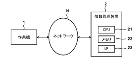
- FIG. 1B is a block diagram showing a configuration example of the work system SY.
- the work system SY includes a work machine (work vehicle) 1, an information management device (server) 2 and a station 3.
- FIG. 1A shows a work machine 1, an information management device 2 and a station 3, and a house H of their owners.
- the work machine 1 performs a predetermined work in the work area WR.
- the work area WR is the garden (turf) of the house H
- the work content is lawn mowing work
- the work machine 1 is an unmanned traveling lawn mower.
- the concept of the working machine 1 includes a snow removing machine and an agricultural working machine (for example, cultivating machine) in addition to the lawn mower. ..
- FIG. 1 shows a mountain-shaped or convex region R CC and a valley-shaped or concave region R CV as an example of this undulation.
- the work machine 1 and the information management device 2 can communicate with each other via the network N, and the work machine 1 performs the above work while exchanging necessary information with the information management device 2 to manage the information.
- the device 2 manages information related to the work (for example, information indicating work status).
- the information management device 2 includes a central processing unit (CPU) 21, a memory 22, and an external communication interface 23.
- the information management device 2 performs information communication with the work machine 1 via the network N, and also the work machine 1 Process the information received from or transmitted to the work machine 1.
- the information management device 2 is installed in the owner's house H of the work area WR, but as another embodiment, the information management device 2 is installed relatively far from the work area WR. Good.
- the function of the information management device 2 can be realized by the CPU 21 executing a predetermined program in this embodiment, but as another embodiment, a PLD (programmable logic device), an ASIC (special purpose semiconductor integrated circuit). ) Or the like. That is, the function of the information management device 2 can be realized by both software and hardware.
- the program is assumed to be stored in the memory 22 in advance, but as another embodiment, it may be provided via a network or a storage medium.
- the station 3 is installed in a work area WR (for example, on the side of the house H or at the end of the work area WR), and the work machine 1 is housed in the station 3 while it is not working. Although details will be described later, the working machine 1 operates based on a built-in battery, and the station 3 enables charging of the battery while the working machine 1 is accommodated.
- the station 3 may be referred to as a charging station.
- FIG. 1C is a block diagram showing a configuration example of the work machine 1.
- the work machine 1 includes a work unit 101, a work control unit 102, a traveling unit 103, a traveling control unit 104, a measuring unit 105, a computing unit 106, an information holding unit 107, a battery 108, and a charging connector unit 109.
- the work unit 101 is configured to be able to perform work in the work area WR, and in the present embodiment, includes a lawn mowing blade 1011 and a motor 1012 provided in the lower portion of the vehicle body 10 of the work machine 1.
- the blade 1011 is provided in the shape of a disk, and receives power from the motor 1012 to rotate to cut grass in the work area WR.
- a known electric motor such as a three-phase induction motor may be used as the motor 1012.
- the work control unit 102 is an electrical component formed by mounting one or more electronic components such as a semiconductor IC on a printed wiring board, and controls the drive of the work unit 101.
- the traveling unit 103 is provided below the vehicle body 10 so as to be able to travel the working machine 1.
- the traveling unit 103 includes a motor 1031, a pair of left and right rear wheels 1032 that are drive wheels, and a pair of left and right front wheels 1033 that are driven wheels. including.
- the motor 1031 is provided for each of the pair of rear wheels 1032 and can individually drive these.
- a known electric motor may be used for the motor 1031 as in the motor 1012.
- the motor 1031 enables the working machine 1 to move forward, backward, turn (right turn or left turn), etc. by adjusting the rotation direction and the number of rotations of each of the pair of rear wheels 1032.
- the traveling control unit 104 is an electrical component in which one or more electronic components are mounted on a printed wiring board, and controls the driving of the traveling unit 103.
- the measurement unit 105 is a sensor group for acquiring information related to the operation of the work machine 1, such as the traveling state of the work machine 1, the work mode, and the surrounding environment, and includes, for example, a camera 1051 and a G sensor 1052. ..
- the camera 1051 can acquire information around the work machine 1 (topography of the work area WR, presence or absence of obstacles, etc.).
- the camera 1051 is assumed to image the front of the work machine 1.
- the work machine 1 changes the direction at that position, images the surroundings with the camera 1051, and based on the image information obtained by this and the direction of the work machine 1 in the work area WR, the work area WR It is also possible to obtain topographical information.
- the camera 1051 may be an omnidirectional camera capable of capturing an image around the work machine 1.
- the G sensor 1052 can detect the posture of the work machine 1 (the inclination of the vehicle body 10 with respect to the horizontal direction, etc.).
- the measurement unit 105 may further include various sensors in addition to the camera 1051 and the G sensor 1052.
- the measurement unit 105 may further include a GPS (Global Positioning System) sensor for acquiring information indicating the position of the device itself in the work area WR.
- the measuring unit 105 can further include a humidity sensor, a temperature sensor, an atmospheric pressure sensor, and the like that can acquire environmental information around the work machine 1.
- the measurement unit 105 is a sensor for acquiring information necessary for calculating the position of the own device based on the odometry method (for example, a sensor for detecting the rotation speed of the wheel, a steering angle, etc.). Can be further included.
- the arithmetic unit 106 performs arithmetic processing for performing overall control of the work machine 1 and functions as a system controller.
- the calculation unit 106 includes a CPU 1061, a memory 1062, and an external communication interface 1063, and can exchange signals and information with each element of the work machine 1 via, for example, a bus. There is.
- the calculation unit 106 outputs a control signal to the work control unit 102 to drive the work unit 101, or receives a predetermined detection signal from the work control unit 102 to detect the load on the work unit 101.
- the calculation unit 106 can also receive a signal or information indicating a predetermined measurement result from the measurement unit 105 and perform drive control of each element or feedback control of each element by calculation processing based on the signal or information. Although details will be described later, the calculation unit 106 also functions as a travel route determination device for determining the travel route of the work machine 1. The function of the calculation unit 106 can be realized by either software or hardware, like the information management device 2.
- a non-volatile memory such as an EEPROM or a flash memory, or any other known storage medium is used for the information holding unit 107, and the details will be described later, but the information holding unit 107 can hold predetermined information. Further, the arithmetic unit 106 can read necessary information from the information holding unit 107 and perform arithmetic processing, and can also store the result obtained by the arithmetic processing in the information holding unit 107. ..
- the battery 108 a rechargeable secondary battery such as a lithium ion battery or a nickel hydride battery is used.
- the charging connector unit 109 is provided so as to be electrically connectable to the station 3, and in the state electrically connected to the station 3, the battery 108 is charged by the electric power supplied from the station 3.
- the charging connector portion 109 is provided in the front portion of the vehicle body 10 in this embodiment, but may be provided in the rear portion of the vehicle body 10 as another embodiment.
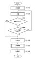
- FIG. 2A is a flowchart showing an example of a work mode by the work machine 1.
- the work and traveling of the work machine 1 are realized mainly by the arithmetic processing by the arithmetic unit 106 and drive control of each element of the work machine 1 based on the result, and the following steps are mainly performed by the arithmetic unit 106.
- this flowchart is started, for example, when a command for starting work is input by a user such as an owner, and the work machine 1 is stored in the station 3 until then.
- This work start command is input using the information management device 2 or as a part of the information management device 2 via a mobile terminal (for example, a smartphone), and when the work start reservation function is used, the work start command is input. It shall be entered at the set time.
- step S1010 (hereinafter, simply referred to as “S1010”; the same applies to other steps)), the initial settings required to start the work are performed.
- the terrain information of the work area WR is held in advance in the information holding unit 107, and the calculation unit 106 reads out this terrain information from the information holding unit 107, and also stores each element of the work machine 1. Put it in a drivable state.
- the topographical information includes horizontal and vertical coordinate information about the work area WR. That is, the topographical information is map information including information indicating the outer shape of the work area WR in a top view and information about the height direction (elevation information), and may be expressed as three-dimensional coordinate information or the like.
- the work machine 1 starts from the station 3 and puts the work unit 101 into an operating state to start work in the work area WR.
- the work machine 1 heads to the designated portion of the work area WR and performs work there.
- the work implement 1 proceeds with the work while detecting its own position using the above-mentioned topographical information of the work area WR, but the work aspect is not limited to this.
- the work machine 1 may proceed with the work while detecting a predetermined installation object in the work area WR, and as an example, while detecting an electromagnetic wave from a wire that defines the work area WR. It is also possible to work.
- S1030 it is determined whether or not there is a return instruction. If there is a return instruction, the process proceeds to S1050, and if not, the process proceeds to S1040.
- the return command is input by the user using the information management device 2 or as a part of the information management device 2 via the mobile terminal, and when the work end reservation function is used, input at the work end set time. Shall be done.
- the process proceeds to S1050, and if not, the process returns to S1020 to continue the work.
- the reference amount may be set to a value sufficient for the work implement 1 to return to the station 3 from any position within the work area WR.
- step S1050 the work unit 1 is stopped and the work is interrupted in response to the return instruction in S1030 or in S1040 when the remaining amount of the battery 108 becomes less than the reference amount.
- step S1060 although the details will be described later, a calculation process for determining a traveling route to the station 3 is performed.
- step S1070 the vehicle returns to the station 3 along the travel route determined in step S1060, and the present flow chart ends.
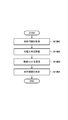
- FIG. 2B is a flowchart showing the contents of the arithmetic processing of S1060. According to this flowchart, from the position (current location) of the work implement 1 to the charging station 3 (destination) when there is a return instruction (S1030) or when the remaining amount of the battery 108 is less than the reference amount (S1040). Determine the travel route.
- topographical information of the work area WR is acquired.
- This topographical information is previously stored in the information storage unit 107 as described above, and has already been read in S1010. Therefore, in the present embodiment, the calculation unit 106 diverts the topographical information read in S1010.
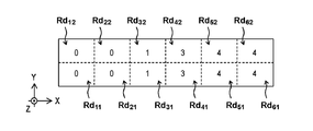
- FIG. 3A is a schematic diagram for explaining the terrain information of the work area WR.
- the X direction, the Y direction, and the Z direction are shown.
- the X direction and the Y direction correspond to the horizontal directions orthogonal to each other, and the Z direction is the X direction and the Y direction. It shall correspond to the vertical direction orthogonal to both.
- the work area WR is virtually divided into a plurality of areas.
- the work area WR has a total of 12 squares, 6 squares in the X direction and 2 squares in the Y direction, so that each area is a quadrangle. It is assumed to be divided. Each of these divided areas may be expressed as a “divided area” below.
- the i-th one in the X direction and the j-th one in the Y direction are set as divided areas Rd ij , and, for example, the fifth one in the X direction and the second one in the Y direction are divided.
- the area is Rd 52 .
- the divided regions Rd 11 , Rd 21 , Rd 12 and Rd 22 form a horizontal plane (a flat surface parallel to both the X direction and the Y direction).
- the divided areas Rd 51 , Rd 61 , Rd 52, and Rd 62 form a horizontal plane at a position higher than the divided areas Rd 11 , Rd 21 , Rd 12, and Rd 22 (position in the + Z direction).
- the divided areas Rd 31 , Rd 41 , Rd 32, and Rd 42 connect the divided areas Rd 11 , Rd 21 , Rd 12, and Rd 22 to the divided areas Rd 51 , Rd 61 , Rd 52, and Rd 62.
- the inclined surface is formed as described above.
- the term "inclination" used herein refers to a mode that is neither horizontal nor vertical, that is, a mode that intersects with one or both of the X direction and the Y direction and intersects with the Z direction.
- the gradient distribution of the work area WR is evaluated. This evaluation is performed based on the above-mentioned topographical information, and thereby, the aspect of the gradient of the work area WR (whether there is undulation, unevenness, height difference, etc., and its degree) is evaluated.
- FIG. 3B shows the evaluation result of the gradient distribution based on the terrain information (see FIG. 3A) of the work area WR.
- elevation information is given to each of the divided areas Rd 11 to Rd 62 .
- the positions of the divided areas Rd 31 and Rd 32 at positions relatively higher than those in the Z direction. For example, Z 1 is given to the information.
- the movement cost between the divided regions Rd 11 to Rd 62 is set based on the evaluation result of S1062.
- This movement cost may be set based on the height difference (positional information in the Z direction) of adjacent ones of the divided regions Rd 11 to Rd 62 , and when moving from one of them to the other. It is possible to cope with the probability of occurrence of an unexpected situation that may occur in. For example, when the inclination angle of the traveling surface of the work machine 1 is increased, slipping of the work machine 1 and accompanying peeling of the work area WR (turf) are likely to occur. Therefore, it is preferable that the movement cost is set high for movement when traveling on a surface having a large inclination angle.
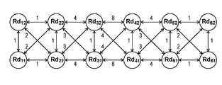
- FIG. 3C shows an example of setting the movement cost between the divided areas Rd 11 to Rd 62 .
- the movement cost from the divided area Rd 11 to the divided area Rd 21 is set to “1”.
- This cost is conveniently set as a cost corresponding to a moving distance of one square in the X direction, since there is no difference in height between the divided areas Rd 11 and Rd 21 .
- the movement cost from the divided area Rd 11 to the divided area Rd 22 is set to “2”.
- This cost is conveniently set as a cost corresponding to a moving distance of one square in the diagonal direction (X direction and Y direction) without any difference in height between the divided regions Rd 11 and Rd 22. ..
- the movement cost from the divided area Rd 21 to the divided area Rd 31 is set to “4”, for example. Since this cost has a height difference between the divided areas Rd 21 and Rd 31 , based on both the cost corresponding to the moving distance of one square in the X direction and the cost corresponding to the inclination due to this height difference, It is set for convenience.
- the movement cost from the divided area Rd 21 to the divided area Rd 32 is set to, for example, “3”. Although there is a difference in height between the divided regions Rd 21 and Rd 32 , the inclination is gentler than that between the divided regions Rd 21 and Rd 31 . Therefore, this cost is conveniently set based on both the cost corresponding to the movement distance of one square in the diagonal direction and the cost corresponding to the loosened inclination. That is, the moving cost from the divided area Rd 21 to the divided area Rd 32 is set to a value smaller than the moving cost from the divided area Rd 21 to the divided area Rd 31 .
- the movement cost from the divided area Rd 31 to the divided area Rd 41 is set to “8”, for example. Since this cost has a height difference between the divided regions Rd 31 and Rd 41 , based on both the cost corresponding to the moving distance of one square in the X direction and the cost corresponding to the inclination due to this height difference, It is set for convenience. Since the height difference between the divided regions Rd 31 and Rd 41 is larger than the height difference between the divided regions Rd 21 and Rd 31 , the movement cost from the divided region Rd 31 to the divided region Rd 41 is divided from the divided region Rd 21. It is set to a value larger than the cost of moving to the area Rd 31 .
- the movement cost from the divided area Rd 31 to the divided area Rd 42 is set to “4”, for example. Although there is a difference in height between the divided regions Rd 31 and Rd 42 , the inclination is gentler than that between the divided regions Rd 31 and Rd 41 . Therefore, this cost is conveniently set based on both the cost corresponding to the movement distance of one square in the diagonal direction and the cost corresponding to the loosened inclination. That is, the moving cost from the divided area Rd 31 to the divided area Rd 42 is set to a value smaller than the moving cost from the divided area Rd 31 to the divided area Rd 41 .
- the movement cost between the divided areas is set mainly based on the degree of inclination due to the height difference between the divided areas.
- the movement cost between the divided areas adjacent to each other is set to the same value in any direction.
- the movement cost from the divided area Rd 31 to the divided area Rd 42 is set to “4”, but the movement cost from the divided area Rd 42 to the divided area Rd 31 is also set to “4”. I shall.
- the travel route is determined based on the travel cost set in S1063.
- the travel route from the divided area Rd 11 corresponding to the current location to the divided area Rd 62 corresponding to the destination is determined.
- the travel route may be determined so that the movement cost between the divided areas from the divided area Rd 11 to the divided area Rd 62 satisfies a predetermined condition.
- the travel route is such that the total value of the travel costs when passing through the travel route becomes smaller than the reference value or takes the minimum value, or the travel cost between the divided areas is It may be determined so that the reference value is not exceeded.
- the total travel cost of route C is 12, which is smaller than the total travel cost of routes A and B. Further, even if the movement costs of other routes are taken into consideration, there is no route smaller than the total value of the movement costs of the route C. Therefore, in the example of FIG. 3C, the route C is selected and determined as the traveling route from the divided region Rd 11 (current position) to the divided region Rd 62 (destination).
- the contents of the arithmetic processing of FIG. 2B are described using the models shown in FIGS. 3A to 3C for convenience, but the work region WR has a vast area and complicated undulations. Therefore, the actual calculation processing by the calculation unit 106 can be complicated. Therefore, a predetermined simplified model can be used for the arithmetic processing of the arithmetic unit 106. For example, in the evaluation of the gradient distribution of the work area WR, after the coordinate information is given to each divided area (Rd 11 etc.) based on the topographical information of the work area WR, the movement cost is set based on the coordinate information. Therefore, it can be realized relatively easily.
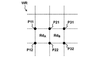
- FIG. 4A is a schematic diagram for explaining coordinate information of divided areas (for example, divided areas Rd A and Rd B ).
- the work area WR is virtually divided into a plurality of areas by the calculation unit 106.
- the calculation unit 106 divides the work area WR so that each divided region becomes a quadrangle, and the calculation unit 106 gives coordinate information based on the coordinates of the corners to each divided region. ..
- the calculation unit 106 gives the average value of the coordinates of the corners of a certain divided area as coordinate information.
- the corners of the other divided regions Rd B are defined as points P 21 , P 31 , P 22 and P 32 .
- the work area WR is divided so that each divided area becomes a quadrangle, but the shape of the divided area is not limited to this, and the work area WR may have various shapes. It is divisible.
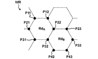
- the work area WR may be divided so that each divided area is a hexagon.
- the coordinate information of each divided area is given based on the coordinates of the corner.
- the coordinate information of a certain divided area Rd A in FIG. 4B gives the average value of the coordinates of the corner points P 11 , P 12 , P 21 , P 22 , P 31 and P 32 as the coordinate information.
- the coordinate information of the other divided areas Rd B gives the average value of the coordinates of the corner points P 22 , P 23 , P 32 , P 33 , P 42, and P 43 as coordinate information.
- each divided area may be based on the coordinates of the corner, and in the present embodiment, the average value thereof is used, but in another embodiment, it may be the median value thereof. Alternatively, or additionally, the calculated value may take into consideration the standard deviation or the like.
- the work area WR is supposed to be virtually divided into a plurality of areas by the calculation unit 106, but the division mode may be predetermined according to a predetermined rule.
- the information for specifying the rule may be included in the topographical information of the work area WR as attribute information.
- the coordinate information assigned to each divided area may be included in the topographical information of the work area WR as attribute information.
- the movement cost between divided areas is set based on this coordinate information.
- the movement cost is set mainly based on the degree of inclination due to the height difference between the divided areas. Additionally, the movement cost may be set based on the height difference itself.
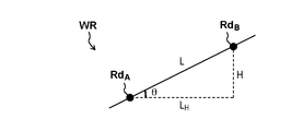
- FIG. 5 is a schematic diagram for explaining an example of a method of setting the movement cost between the divided areas Rd A -Rd B.
- Cost of moving between the divided regions Rd A -Rd B includes a coordinate information given to the dividing regions Rd A, is set based on the coordinate information given to the divided region Rd B.
- the coordinate in the divided region Rd A (X A, Y A , Z A) is given, the coordinates in the divided region Rd B (X B, Y B , Z B) shall be given.
- the distance L is the coordinates (X A, Y A, Z A) - the coordinates (X B, Y B, Z B) indicates the distance between the distance L H is between the divided regions Rd A -Rd B Of the divided regions Rd A -Rd B in the horizontal direction.
- L ⁇ (X A ⁇ X B ) 2 + (Y A ⁇ Y B ) 2 + (Z A ⁇ Z B ) 2 ⁇ 1/2
- L H ⁇ (X A ⁇ X B ) 2 + (Y A ⁇ Y B ) 2 ⁇ 1/2
- H
- , Can be expressed as Further, the inclination angle ⁇ between the divided areas Rd A -Rd B is ⁇ arcsin (H / L), Can be expressed as
- the moving cost (moving cost C AB ) when moving from the divided area Rd A to the divided area Rd B can be evaluated using various simple models, and for example, the inclination angle ⁇ (0 ° ⁇ ⁇ ⁇ 90. Is used as an evaluation value.
- the larger the inclination angle ⁇ the larger the movement cost C AB (C AB ⁇ K 0 at ⁇ ⁇ 90 °).
- the movement cost C AB may be set to a predetermined value when traveling on a horizontal plane and to increase as the inclination angle ⁇ increases.
- the larger the inclination angle ⁇ the larger the movement cost C AB (C AB ⁇ ⁇ at ⁇ ⁇ 90 °).
- the moving cost C AB has the same meaning as in the second example.
- C AB L ⁇ (K 2 + K 3 ⁇ sin ⁇ )
- K 2 coefficient (K 2 ⁇ 0)
- K 3 coefficient (K 3 ⁇ 0)
- the moving cost C AB also increases (C AB ⁇ L ⁇ (K 2 + K 3 ) at ⁇ ⁇ 90 °).
- K 3 > K 2 it becomes possible to set the movement cost with emphasis on the degree of inclination.
- the moving cost C AB may be a combination of these setting methods, or another function according to the simplified model is further used. It may be combined.
- the above-described movement cost may be set by using the height difference H or using the height difference H and the distance L H without using the inclination angle ⁇ , which reduces the processing load of the calculation unit 106. It is also possible to reduce it.
- the coordinate information assigned to each divided area may further include information indicating the degree of inclination of the divided area itself, and for the above-mentioned movement cost, refer to this information incidentally. May be set by.
- the movement cost between divided areas is set to be the same value in any direction, but the movement cost in one direction and the movement cost in the other direction are For example, they may be set individually by using different expressions or different coefficients. That is, even if the moving cost C AB when moving from the divided area Rd A to the divided area Rd B and the moving cost C BA when moving from the divided area Rd B to the divided area Rd A have different values. Good.
- the traveling route from the current position to the destination is determined based on the set movement cost.
- the travel route is determined so that the total value of the movement costs between the divided regions forming the travel route is the minimum.
- the travel route is determined based on the movement cost between the divided areas set above, but other elements may be additionally referred to in the determination.
- the probability of occurrence of an unexpected situation may vary depending on the surrounding environment of the work machine 1. Therefore, the travel route may be determined based on the environmental information around the work machine 1.
- Examples of the above environmental information include information such as humidity, temperature, and atmospheric pressure.
- the information on the humidity, temperature, atmospheric pressure and the like can be acquired by various sensors of the measuring unit 105, for example.
- the coefficient of friction between the running portion 103 and the running surface may also change, which may affect the probability of occurrence of the unexpected situation. For example, it can be said that when the humidity is high, slip is likely to occur when traveling on an inclined surface. Therefore, the travel route may be determined in consideration of this fact.
- weather information is another example of the environmental information.
- the weather information can be acquired via the network N, for example.
- the concept of the weather information includes not only information indicating the present weather but also information about relatively near future weather. For example, when it is predicted that it will rain in the relatively near future, the travel route may be determined in consideration of this fact.
- Such environment information may be used at the time of S1063, that is, may be used for an equation when setting the movement cost, for example, adjustment of numerical values such as the coefficient K 0 .
- the coefficient K 0 or the like should be changed so that the moving cost C AB becomes larger (as compared with the case where the humidity is relatively low) as the inclination angle ⁇ becomes larger. Is possible.
- an allowable range of ups and downs through which the work machine 1 can pass may be set on the basis of such environmental information, that is, the allowable range limits a part of the traveling route in S1064. May be applied to.
- the calculation unit 106 may determine the travel route so as not to move between the divided areas having a movement cost corresponding to the above-described allowable range or a movement cost higher than that in S1064, for example. Thereby, for example, when the degree of inclination in any part of a certain traveling route does not satisfy the above-mentioned allowable range (even if the total value of the moving costs of the traveling route is the minimum), the calculation unit 106. Will select another travel route without selecting that travel route.
- the division of the work area WR into a plurality of areas does not necessarily have to be performed uniformly as illustrated in FIGS. 4A and 4B, and the division mode may be partially changed. Examples of changing the division mode include changing the division density (the number of divisions per unit area of the work area WR) or the division area (area per division area).
- the work area WR may be divided into a plurality of divided areas Rd L and Rd S having different sizes and shapes.
- the large-sized divided region Rd L is formed in the X direction and the Y direction
- the small-sized divided region Rd S is formed in the diagonal direction thereof. Therefore, the divided region Rd L has an octagonal shape, and the divided region Rd S has a quadrangular shape. According to such a division mode, it is possible to highly accurately evaluate the movement cost in the diagonal direction, and it is possible to more appropriately determine the traveling route of the work machine 1 in S1060.
- the division mode may be changed so that the division area of the portion where the undulation exists is smaller than the other division areas.
- the region including the mountain-shaped or convex-shaped region R CC has a small size as shown by a dashed line in the drawing. It is divided (referred to as a divided area Rd ′).
- the area including the area R CC is further divided into smaller sizes as indicated by the chain double-dashed line in the figure (referred to as divided areas Rd ′′).
- the case of the convex region R CC is illustrated, but the same applies to the case of the valley or concave region R CV .
- a region including the region R CC (or R CV ) has a small size divided region Rd.
- the shapes of the divided regions Rd, Rd ′, and Rd ′′ are not limited to these examples, and the work region RW can be divided into various shapes and various sizes. Therefore, the divided regions Rd, Rd ′, and Rd ′ can be divided.
- Rd ′′ may be, for example, a trapezoid, or a polygon in which the lengths of all sides are different from each other. Even in such a case, the coordinate information can be given to each of the divided areas Rd, Rd ', and Rd "by the same procedure as described above (see FIGS. 4A and 4B).
- the calculation unit 106 functions as a travel route determination device, acquires the terrain information of the work area WR (see S1061 in FIG. 2), and then calculates the work area WR based on the terrain information.
- the gradient distribution is evaluated (see S1062).
- This topographical information includes horizontal and vertical coordinate information about the work area WR (see FIG. 3A), and the calculation unit 106 can perform the evaluation of the gradient distribution by a relatively simple calculation process. (See Figures 3B and 3C).
- the calculation unit 106 based on the evaluation result of the gradient distribution, the travel route from the current position of the work machine 1 to the destination (for example, the charging station 3) in the work region WR, the undulation in the travel route becomes small. (See S1063 to S1064).
- the traveling route of the work machine 1 can be appropriately determined in consideration of the undulations of the work area WR.
- the terrain information of the work area WR may include various types of information, and the travel route may be determined by further referring to these pieces of information.
- the terrain information may further include information indicating the number of convex regions R CC or concave regions R CV existing in each divided region Rd (concavo-convex number information). For example, even if the movement cost between certain divided regions is relatively low, if the number of regions R CC or R CV existing in one or the other of the divided regions is relatively large, the divided regions are passed through. Determine the travel route so as not to. This is useful when the region R CC or R CV is relatively small, so that, for example, the wheels 1032 or 1033 will fit into the region R CC or R CV when passing through the divided region.
- an unmanned traveling lawnmower provided with the battery 108 is illustrated as the working machine 1, but in this example, when the remaining amount of the battery 108 becomes less than the reference amount, the charging station 3 as the destination is provided. It is possible to appropriately determine the travel route for returning appropriately. According to the present embodiment, the work implement 1 does not pass through a relatively steep slope when returning from the current location to the charging station 3 as the destination. As a result, it is possible to prevent the occurrence of unexpected situations such as slipping of the working machine 1 that may occur when the work machine 1 passes through the inclined surface and accompanying peeling of the grass. Further, by returning along the appropriate travel route, the work machine 1 can also return to the charging station 3 at a vehicle speed higher than the vehicle speed during work. The same applies to the configuration in which the battery 108 is not provided, that is, even in such a case, the work implement 1 does not pass through a relatively steep inclined surface (unforeseen circumstances caused by this). The destination can be properly reached (without causing it).
- the calculation process for determining the traveling route may be performed in the calculation unit 106 of the work machine 1, but may be performed outside the work machine 1, for example, in the information management device 2.
- the information management device 2 functions as a travel route determination device, and the working machine 1 receives the result of the arithmetic processing from the information management device 2 and travels along the traveling route based on the result of the arithmetic processing. Good.
- the terrain information of the work area WR is assumed to be held in advance in the information holding unit 107, but as another embodiment, the terrain information can be received from the information management device 2. ..
- the terrain information may be generated by the work machine 1 itself, and for example, the calculation unit 106 may perform terrain based on the measurement result of the measuring unit 105 (mainly image information obtained by the camera 1051). Information may be generated and the topographical information may be stored in the information holding unit 107. In this case, when the working machine 1 travels in the work area WR and acquires topographical information before starting the first work for the work area WR, the Topographic information becomes available. Further, when performing the second and subsequent operations, this topographical information can be read from the information holding unit 107.
- a first aspect relates to a travel route determination device (for example, 106, 2), and the travel route determination device determines a travel route for determining a travel route of a work machine (for example, 1) in a work area (for example, WR).
- An acquisition unit for example, S1061 that acquires topographical information of the work area
- an evaluation unit for example, S1062 to S1063 that evaluates the gradient distribution of the work area based on the topographical information
- a determining unit for example, S1064 that determines the traveling route of the working machine from the current position to the destination on the basis of the gradient distribution so as to reduce the undulations on the traveling route.
- the travel route of the work machine in consideration of the ups and downs of the work area. For example, when a relatively steep inclined surface is avoided and the inclined surface is passed, It is possible to prevent the occurrence of unexpected situations such as slippage of the working machine.
- the topographical information includes horizontal and vertical coordinate information about the work area.
- the gradient distribution of the work area can be evaluated by a relatively simple calculation process.
- the topographical information includes coordinate information given to each of a plurality of areas (for example, Rd) obtained by virtually dividing the work area.
- the gradient distribution of the work area can be evaluated by a simpler arithmetic process.
- the evaluation unit evaluates a movement cost (for example, C AB ) when moving between the regions based on a gradient between the regions obtained from the coordinate information, and the determination unit, A travel route from the current location to the destination is determined so that the total value of the travel costs between the regions forming the travel route is minimized.
- a movement cost for example, C AB
- the fourth aspect it is possible to calculate the total value of the travel costs when traveling along the travel route from the current position to the destination by cumulative addition of the travel costs between the divided areas, and therefore, determine the optimum travel route. It will be possible.
- the divided regions include a first region (for example, Rd A ) and a second region (for example, Rd B ) that are adjacent to each other and are provided with the coordinate information of different heights. Therefore, the evaluation means may include the movement cost (for example, C AB ) when moving from the first area to the second area and the movement cost (when moving from the second area to the first area ( For example, C BA ) and are separately evaluated.
- the fifth aspect it is possible to more appropriately determine the travel route by evaluating different moving costs when moving up the slope and when moving down the slope. ..
- peeling of the grass, which is the work area is more likely to occur when moving down an inclined surface than when moving up an inclined surface. Therefore, according to the fifth aspect, it can be said that it is advantageous to maintain the work area in an appropriate state.
- the terrain information further includes unevenness number information indicating the number of convex or concave areas existing in each of the divided areas
- the determining unit further includes the unevenness number information. The travel route is determined based on
- the travel route is determined so as not to pass through the divided area. As a result, it is possible to prevent an unexpected situation in which the wheel 1032 or 1033 is unnecessarily fitted into the convex or concave region.
- a second acquisition unit that acquires environment information around the work machine is further provided, and the determination unit further determines the travel route based on the environment information.
- the travel route can be more appropriately determined. It becomes possible to decide.
- the environment information includes information indicating humidity.
- the influence on the traveling of the work machine due to the ups and downs of the traveling surface can be changed depending on, for example, the humidity. Therefore, according to the eighth aspect, the traveling route can be more appropriately determined.
- the environment information includes weather information.
- the influence on the traveling of the work machine due to the undulation of the traveling surface may change depending on, for example, the weather. Therefore, according to the ninth aspect, the traveling route can be more appropriately determined.
- a tenth aspect relates to a work machine (for example, 1), and the work machine includes the above-described travel route determination device (for example, 106), a traveling unit (for example, 103) for traveling a vehicle, and the travel route. And a travel control unit (for example, 104) that controls the travel unit based on the travel route determined by the determination unit of the determination device.
- the work machine includes the above-described travel route determination device (for example, 106), a traveling unit (for example, 103) for traveling a vehicle, and the travel route.
- a travel control unit for example, 104 that controls the travel unit based on the travel route determined by the determination unit of the determination device.
- the traveling route determination device described above can be suitably applied to a general work machine.
- this traveling route determination device can also be used for automatic operation and driving support control of a riding-type working machine.
- a measurement unit for example, 105) for measuring the terrain of the work area
- an information holding unit for example, 107 that holds the measurement result of the measurement unit as the terrain information
- the work machine itself it becomes possible for the work machine itself to acquire the terrain information of the work area.
- a battery for example, 108 is further provided, and when the remaining amount of the battery becomes less than a reference amount, the traveling route determination device sets the charging station as the destination by the determination unit. Determine the travel route.
- the above-described travel route determination device can be preferably applied to a work machine that performs work with power using a battery.
- the work implement interrupts the work and returns to the charging station, and in many cases, the work implement charges at a vehicle speed higher than the working speed. Return to the station. Therefore, it can be said that the traveling route determination device can be preferably used in such an application.
- a method for determining a travel route of a work machine in a work area the step of obtaining topographic information of the work area, and evaluating a gradient distribution of the work area based on the topographic information. And a determination step of determining a travel route from the current position of the work machine to the destination in the work area based on the gradient distribution so that the undulations on the travel route are small.
- Yet another mode is a program for causing a computer to execute each step in the above method.
- Yet another aspect is a computer-readable recording medium in which the above program is recorded.
Abstract
本発明は走行経路決定装置に係り、前記走行経路決定装置は、作業領域における作業機の走行経路を決定するための走行経路決定装置であって、前記作業領域の地形情報を取得する取得手段と、前記作業領域の勾配分布を前記地形情報に基づいて評価する評価手段と、前記作業領域における前記作業機の現在地から目的地までの走行経路を、該走行経路における起伏が小さくなるように、前記勾配分布に基づいて決定する決定手段とを備え、これにより、作業機の走行経路を作業領域の起伏を考慮して決定可能にする。
Description
本発明は、主に作業機に適用可能な走行経路決定装置に関する。
芝刈機等の作業機は、一般に、作業領域における作業を所定の車速で走行しながら順に行う。作業領域は、必ずしも平坦であるとは限らず、何らかの起伏を有することもある(特許文献1参照)。
作業領域の起伏を作業機が通過する際、走行部においてスリップが発生することもある。そのため、作業機の走行経路は、このような作業領域の起伏を考慮して決定されることが求められる場合がある。
本発明の目的は、作業機の走行経路を作業領域の起伏を考慮して決定することにある。
本発明の一つの側面は走行経路決定装置に係り、前記走行経路決定装置は、作業領域における作業機の走行経路を決定するための走行経路決定装置であって、前記作業領域の地形情報を取得する取得手段と、前記作業領域の勾配分布を前記地形情報に基づいて評価する評価手段と、前記作業領域における前記作業機の現在地から目的地までの走行経路を、該走行経路における起伏が小さくなるように、前記勾配分布に基づいて決定する決定手段と、を備えることを特徴とする。
本発明によれば、作業機の走行経路を作業領域の起伏を考慮して決定可能となる。
以下、添付図面を参照しながら本発明の実施形態について説明する。尚、各図は、実施形態の構造ないし構成を示す模式図であり、図示された各部材の寸法は必ずしも現実のものを反映するものではない。また、各図において同一の要素には同一の参照番号を付しており、本明細書において重複する内容については説明を省略する。
図1Aは、実施形態に係る作業システムSYによる作業態様を示す模式図である。図1Bは、作業システムSYの構成例を示すブロック図である。作業システムSYは、作業機(作業用車両)1、情報管理装置(サーバー)2およびステーション3を備える。図1Aには、作業機1、情報管理装置2およびステーション3と併せて、それらのオーナーの家Hが示される。
作業機1は、作業領域WRにおいて所定の作業を行う。本実施形態においては、作業領域WRを家Hの庭(芝地)とし、作業内容を芝刈作業とし、また、作業機1は無人走行式芝刈機とする。尚、作業内容の他の例として除雪作業や農作業(例えば耕運作業)も挙げられ、よって、作業機1の概念には、芝刈機の他、除雪機や農作業機(例えば耕運機)も含まれる。
詳細については後述とするが、作業領域WRは、必ずしも平坦ではなく、一般に傾斜や段差等で形成される起伏を有する。図1には、この起伏の例として、山状あるいは凸状の領域RCC、及び、谷状あるいは凹状の領域RCVを示す。
作業機1と情報管理装置2とはネットワークNを介して相互に通信可能であり、作業機1は、情報管理装置2との間で必要な情報の授受を行いながら上記作業を行い、情報管理装置2は、上記作業に関連する情報(例えば作業状況を示す情報など)を管理する。情報管理装置2は、中央演算装置(CPU)21、メモリ22、及び、外部通信インタフェース23を備え、例えば、ネットワークNを介して作業機1との間で情報通信を行い、また、作業機1から受信した情報あるいは作業機1に送信する情報を処理する。ここでは、情報管理装置2は作業領域WRのオーナーの家H内に設置されるものとするが、他の実施形態として、情報管理装置2は作業領域WRから比較的離れた場所に設置されてもよい。
尚、情報管理装置2の機能は、本実施形態ではCPU21が所定のプログラムを実行することにより実現されうるが、他の実施形態として、PLD(プログラマブルロジックデバイス)、ASIC(特定用途向け半導体集積回路)等により実行されてもよい。即ち、情報管理装置2の機能は、ソフトウェア及びハードウェアの何れによっても実現可能である。尚、本実施形態では、上記プログラムは、メモリ22に予め格納されているものとするが、他の実施形態として、ネットワークや記憶媒体を介して提供されてもよい。
ステーション3は作業領域WR(例えば家Hの側方等、作業領域WRの端部)に設置され、作業機1は、作業を行っていない間、このステーション3に収容される。詳細については後述とするが、作業機1は内蔵バッテリに基づいて動作し、ステーション3は、作業機1を収容している間、このバッテリを充電可能とする。ステーション3は、充電用ステーションと表現されてもよい。
図1Cは、作業機1の構成例を示すブロック図である。作業機1は、作業部101、作業制御部102、走行部103、走行制御部104、計測部105、演算部106、情報保持部107、バッテリ108及び充電用コネクタ部109を備える。
作業部101は、作業領域WRでの作業を実現可能に構成され、本実施形態では、作業機1の車体10下方部に設けられた芝刈用ブレード1011およびモータ1012を含む。ブレード1011は、ディスク状に設けられており、モータ1012からの動力を受けて回転することにより作業領域WRの芝を刈り取る。モータ1012には、例えば三相誘導モータ等、公知の電動モータが用いられればよい。作業制御部102は、例えば半導体IC等の1以上の電子部品がプリント配線基板に実装されて成る電装部品であり、作業部101の駆動制御を行う。
走行部103は、車体10下方部において作業機1を走行可能に設けられ、本実施形態では、モータ1031、駆動輪である左右一対の後輪1032、及び、従動輪である左右一対の前輪1033を含む。モータ1031は、一対の後輪1032の個々に対して設けられ、これらを個別に駆動可能とする。モータ1031には、モータ1012同様、公知の電動モータが用いられればよい。例えば、モータ1031は、一対の後輪1032の個々の回転方向および回転数を調整することにより作業機1の前進、後退、旋回(右折または左折)等を可能とする。走行制御部104は、作業制御部102同様、1以上の電子部品がプリント配線基板に実装されて成る電装部品であり、走行部103の駆動制御を行う。
計測部105は、例えば作業機1の走行状態、作業態様、周囲の環境等、作業機1の動作に関連する情報を取得するためのセンサ群であり、例えば、カメラ1051およびGセンサ1052を含む。カメラ1051は、作業機1の周囲の情報(作業領域WRの地形、障害物の有無など)を取得可能とする。本実施形態では、カメラ1051は作業機1前方についての撮像を行うものとする。例えば、作業機1は、その位置で向きを変えながらカメラ1051により周囲の撮像を行い、それにより得られる画像情報と、作業領域WR内における作業機1の向きとに基づいて、作業領域WRの地形情報を取得することも可能とする。尚、他の実施形態として、カメラ1051には、作業機1周囲の様子を撮像可能な全方位カメラが用いられてもよい。Gセンサ1052は、作業機1の姿勢(水平方向に対する車体10の傾き等)を検出可能とする。
計測部105は、カメラ1051およびGセンサ1052の他、多様なセンサを更に含みうる。例えば、計測部105は、作業領域WRにおける自機位置を示す情報を取得するためのGPS(Global Positioning System)センサを更に含みうる。また、例えば、計測部105は、作業機1周辺の環境情報を取得可能な湿度センサ、温度センサ、気圧センサ等を更に含みうる。また、例えば、計測部105は、自機位置の算出をオドメトリ法に基づいて行うのに必要な情報を取得するためのセンサ(例えば、車輪の回転数、操舵角等を検出するためのセンサ)を更に含みうる。
演算部106は、作業機1の全体制御を行うための演算処理を行い、システムコントローラとして機能する。本実施形態では、演算部106は、CPU1061、メモリ1062、及び、外部通信インタフェース1063を含み、例えばバスを介して、作業機1の各要素との間で信号ないし情報の授受が可能となっている。例えば、演算部106は、作業制御部102に制御信号を出力して作業部101を駆動し、或いは、作業制御部102から所定の検出信号を受け取って作業部101の負荷を検出する。また、演算部106は、計測部105から所定の計測結果を示す信号ないし情報を受け取り、それに基づく演算処理により、各要素の駆動制御あるいは各要素についてのフィードバック制御を行うことも可能である。詳細については後述とするが、演算部106は、作業機1の走行経路を決定するための走行経路決定装置としても機能する。尚、演算部106の機能は、情報管理装置2同様、ソフトウェア及びハードウェアの何れによっても実現可能である。
情報保持部107には、EEPROM、フラッシュメモリ等の不揮発性メモリ、その他の公知の記憶媒体が用いられ、詳細については後述とするが、情報保持部107は、所定の情報を保持可能とする。また、演算部106は、この情報保持部107から必要な情報を読み出して演算処理を行うことも可能であるし、演算処理により得られた結果を情報保持部107に格納することも可能である。
バッテリ108は、リチウムイオン電池、ニッケル水素電池等、充電可能な二次電池が用いられるものとする。充電用コネクタ部109は、ステーション3に電気接続可能に設けられ、ステーション3に電気接続された状態ではステーション3から供給される電力によりバッテリ108が充電される。尚、充電用コネクタ部109は、本実施形態では車体10前方部に設けられるものとするが、他の実施形態として車体10後方部に設けられてもよい。
図2Aは、作業機1による作業態様の一例を示すフローチャートである。作業機1の作業および走行は、主に演算部106による演算処理およびその結果に基づく作業機1の各要素の駆動制御により実現され、以下の各ステップは主に演算部106により行われる。本フローチャートは、例えば、オーナー等のユーザにより作業開始の命令(コマンド)が入力されたことにより開始され、それまでは作業機1はステーション3に格納されているものとする。この作業開始の命令は、情報管理装置2を用いて或いは情報管理装置2の一部として携帯端末(例えばスマートフォン等)を介して入力され、作業開始の予約機能が用いられる場合には作業開始の設定時刻に入力されるものとする。
ステップS1010(以下、単に「S1010」という。他のステップについても同様とする。)では、作業を開始するのに必要な初期設定を行う。本実施形態においては、作業領域WRの地形情報が情報保持部107に予め保持されているものとし、演算部106は、この地形情報を情報保持部107から読み出すと共に、作業機1の各要素を駆動可能な状態にする。詳細については後述とするが、上記地形情報は、作業領域WRについての水平方向および垂直方向の座標情報を含む。即ち、この地形情報は、作業領域WRの上面視での外形を示す情報と、高さ方向に関する情報(標高情報)とを含む地図情報であり、三次元座標情報等と表現されてもよい。
S1020では、作業機1はステーション3から出発すると共に作業部101を稼働状態にして、作業領域WRにおける作業を開始する。作業領域WRの一部について作業を行うことが予めユーザにより指定されている場合には、作業機1は、作業領域WRにおける該指定された部分に向かい、そこで作業を行う。本実施形態では、作業機1は、作業領域WRの上記地形情報を用いて自機位置を検出しながら作業を進めることとするが、作業態様はこれに限られるものではない。例えば、他の実施形態として、作業機1は、作業領域WR内の所定の設置物を検出しながら作業を進めてもよく、一例として、作業領域WRを画定するワイヤからの電磁波を検出しながら作業を行うことも可能である。
S1030では、帰還命令の有無を判定する。帰還命令があった場合にはS1050に進み、そうでない場合にはS1040に進む。帰還命令は、情報管理装置2を用いて或いは情報管理装置2の一部として携帯端末を介してユーザにより入力され、また、作業終了の予約機能が用いられる場合には作業終了の設定時刻に入力されるものとする。
S1040では、バッテリ108の残量が基準量より少なくなったか否かを判定する。バッテリ108の残量が基準量より少ない場合にはS1050に進み、そうでない場合にはS1020に戻って作業を継続する。この基準量には、作業機1が作業領域WR内の何れの位置からでもステーション3に帰還するのに充分な値が設定されていればよい。
S1050では、S1030で帰還命令があったことに応じて又はS1040でバッテリ108の残量が基準量より少なくなったことに応じて、作業部1を停止状態にして作業を中断する。S1060では、詳細については後述とするが、ステーション3までの走行経路を決定するための演算処理を行う。S1070では、S1060で決定された走行経路に沿ってステーション3に帰還し、以上により本フローチャートを終了とする。
図2Bは、S1060の演算処理の内容を示すフローチャートである。本フローチャートにより、帰還命令があった際(S1030)またはバッテリ108の残量が基準量より少なくなった際(S1040)の作業機1の位置(現在地)から充電用ステーション3(目的地)までの走行経路を決定する。
先ず、S1061では、作業領域WRの地形情報を取得する。この地形情報は、前述のとおり情報保持部107に予め保持されており、S1010で既に読み出されている。よって、本実施形態においては、演算部106は、S1010で読み出された地形情報を流用するものとする。
図3Aは、作業領域WRの地形情報を説明するための模式図である。図中には、説明の容易化のため、X方向、Y方向及びZ方向が示され、X方向及びY方向は、互いに直交する水平方向に対応し、Z方向は、X方向及びY方向の双方に直交する垂直方向に対応するものとする。作業領域WRは、仮想的に複数の領域に分割されており、ここでは理解の容易化のため、各領域が四角形となるようにX方向に6マスかつY方向に2マスの計12マスに分割されているものとする。これら分割された領域の個々は、以下において「分割領域」と表現する場合がある。また、これらの分割領域のうち、X方向の第i番目かつY方向の第j番目のものを分割領域Rdijとし、例えば、X方向の第5番目かつY方向の第2番目のものを分割領域Rd52とする。
本例においては、分割領域Rd11、Rd21、Rd12及びRd22は水平面(X方向及びY方向の双方に平行な平坦面)を形成している。また、分割領域Rd51、Rd61、Rd52及びRd62は、分割領域Rd11、Rd21、Rd12及びRd22よりも高い位置(+Z方向の位置)で水平面を形成している。また、分割領域Rd31、Rd41、Rd32及びRd42は、分割領域Rd11、Rd21、Rd12及びRd22と、分割領域Rd51、Rd61、Rd52及びRd62と、を接続するように傾斜した傾斜面を形成しているものとする。尚、ここでいう傾斜とは、水平でもなく且つ垂直でもない態様、即ち、X方向及びY方向の一方又は双方と交差し且つZ方向と交差する態様をいう。
次に、S1062では、作業領域WRの勾配分布の評価を行う。この評価は上記地形情報に基づいて行われ、これにより、作業領域WRの勾配の態様(起伏、凹凸、高低差等の有無、その度合い)についての評価を行う。
図3Bは、作業領域WRの地形情報(図3A参照)に基づく勾配分布の評価結果を示す。ここでは、分割領域Rd11~Rd62の個々について標高情報が与えられる。例えば、分割領域Rd11、Rd21、Rd12及びRd22のZ方向の位置情報を基準(Z=0)として、それらより相対的に高い位置の分割領域Rd31及びRd32のZ方向の位置情報には、例えばZ=1が与えられる。同様にして、分割領域Rd41及びRd42のZ方向の位置情報には、例えばZ=3が与えられ、また、分割領域Rd51、Rd61、Rd52及びRd62のZ方向の位置情報には、例えばZ=4が与えられる。このようにして、作業領域WRの分割領域Rd11~Rd62の勾配分布が評価されうる。
その後、S1063では、S1062の評価結果に基づいて分割領域Rd11~Rd62間の移動コストを設定する。この移動コストは、分割領域Rd11~Rd62のうち、互いに隣り合うものについて、それらの高低差(Z方向の位置情報)に基づいて設定されればよく、それらの一方から他方に移動する際に生じうる不測の事態の発生確率に対応しうる。例えば、作業機1の走行面の傾斜角が大きくなると、作業機1のスリップ、それに伴う作業領域WR(芝地)の剥がれ等が発生する可能性が高くなる。そのため、傾斜角が大きい面を走行する場合の移動に対しては、その移動コストは高く設定されるとよい。
図3Cは、分割領域Rd11~Rd62間の移動コストの設定の一例を示す。例えば、分割領域Rd11から分割領域Rd21への移動コストは「1」に設定されるものとする。このコストは、分割領域Rd11及びRd21間には高低差がなく、X方向1マス分の移動距離に相当するコストとして、便宜的に設定されたものである。また、分割領域Rd11から分割領域Rd22への移動コストは「2」に設定されるものとする。このコストは、分割領域Rd11及びRd22間には高低差がなく、対角方向(X方向かつY方向)1マス分の移動距離に相当するコストとして、便宜的に設定されたものである。
この場合、分割領域Rd21から分割領域Rd31への移動コストは、例えば「4」に設定される。このコストは、分割領域Rd21及びRd31間に高低差があるため、X方向1マス分の移動距離に相当するコストと、この高低差に伴う傾斜に相当するコストとの双方に基づいて、便宜的に設定されたものである。
一方、分割領域Rd21から分割領域Rd32への移動コストは、例えば「3」に設定される。分割領域Rd21及びRd32間には高低差があるものの、分割領域Rd21及びRd31間に比べて傾斜が緩くなる。そのため、このコストは、対角方向1マス分の移動距離に相当するコストと、該緩くなった傾斜に相当するコストとの双方に基づいて、便宜的に設定されたものである。即ち、分割領域Rd21から分割領域Rd32への移動コストは、分割領域Rd21から分割領域Rd31への移動コストよりも小さい値で設定される。
同様に、分割領域Rd31から分割領域Rd41への移動コストは、例えば「8」に設定される。このコストは、分割領域Rd31及びRd41間に高低差があるため、X方向1マス分の移動距離に相当するコストと、この高低差に伴う傾斜に相当するコストとの双方に基づいて、便宜的に設定されたものである。分割領域Rd31及びRd41間の高低差は、分割領域Rd21及びRd31間の高低差よりも大きいため、分割領域Rd31から分割領域Rd41への移動コストは、分割領域Rd21から分割領域Rd31への移動コストよりも大きい値で設定される。
一方、分割領域Rd31から分割領域Rd42への移動コストは、例えば「4」に設定される。分割領域Rd31及びRd42間には高低差があるものの、分割領域Rd31及びRd41間に比べて傾斜が緩くなる。そのため、このコストは、対角方向1マス分の移動距離に相当するコストと、該緩くなった傾斜に相当するコストとの双方に基づいて、便宜的に設定されたものである。即ち、分割領域Rd31から分割領域Rd42への移動コストは、分割領域Rd31から分割領域Rd41への移動コストよりも小さい値で設定される。
詳細については後述とするが、このように、各分割領域間の移動コストは、主に、その分割領域間の高低差に伴う傾斜の度合いに基づいて設定される。尚、図3Cの例では、互いに隣り合う分割領域間の移動コストは、何れの方向についても同一の値で設定されるものとする。例えば、上述のとおり、分割領域Rd31から分割領域Rd42への移動コストは「4」に設定されるが、分割領域Rd42から分割領域Rd31への移動コストも「4」に設定されるものとする。
最後に、S1064では、上記S1063で設定された移動コストに基づいて、走行経路を決定する。ここでは、現在地に対応する分割領域Rd11から、目的地に対応する分割領域Rd62までの走行経路を決定する。走行経路は、分割領域Rd11から分割領域Rd62までに通った各分割領域間の移動コストが所定条件を満たすように決定されればよい。例えば、走行経路は、その走行経路を通った場合の移動コストの合計値が、基準値より小さくなるように、または、最小値をとるように、或いは、各分割領域間の移動コストが何れも基準値を超えないように、決定されるとよい。
例えば、図3Cの例において、移動コストの合計値が最小値となる走行経路を決定する場合について考える。図3Cの例においては、走行経路の候補として、
(経路A) Rd11→Rd21→Rd31→Rd41→Rd51→Rd62、
(経路B) Rd11→Rd21→Rd31→Rd42→Rd52→Rd62、
(経路C) Rd11→Rd21→Rd32→Rd41→Rd52→Rd62、
等が考えられる。ここで、経路Aにおいては移動コストの合計値は19となる。また、経路Bにおいては移動コストの合計値は14となる。これに対して、経路Cにおいては移動コストの合計値は12となり、経路A及びBにおける移動コストの合計値に比べて小さい。また、他の経路の移動コストを考慮しても、経路Cにおける移動コストの合計値より小さい経路はない。よって、図3Cの例においては、分割領域Rd11(現在地)から分割領域Rd62(目的地)までの走行経路として、上記経路Cが選択され決定されることとなる。
以上では、説明の簡易化のため、便宜的に図3A~図3C記載のモデルを用いて図2Bの演算処理の内容を説明したが、作業領域WRは広大な面積を有し且つ複雑な起伏を有しうるため、演算部106による実際の演算処理は複雑になりうる。そのため、演算部106の演算処理には、所定の簡易化モデルが用いられうる。例えば、作業領域WRの勾配分布の評価は、作業領域WRの地形情報に基づいて各分割領域(Rd11等)に座標情報を与えた後に、それらの座標情報に基づいて移動コストを設定することにより、比較的簡便に実現可能である。
図4Aは、分割領域(例えば分割領域RdA及びRdB)の座標情報を説明するための模式図である。作業領域WRは、演算部106により仮想的に複数の領域に分割される。この例では、演算部106は、各分割領域が四角形となるように作業領域WRを分割するものとし、演算部106は、分割領域の個々に対して、そのコーナーの座標に基づく座標情報を与える。例えば、演算部106は、或る分割領域に、そのコーナーの座標の平均値を座標情報として与える。
例えば、分割領域RdAについては、そのコーナーを点P11、P21、P12及びP22とする。これら点P11、P21、P12及びP22の座標は、(X,Y,Z)座標において、
P11=(X11,Y11,Z11)、
P21=(X21,Y21,Z21)、
P12=(X12,Y12,Z12)、
P22=(X22,Y22,Z22)、
と表わせるものとする。この場合、分割領域RdAには、次の式:
XA=(X11+X21+X12+X22)/4;
YA=(Y11+Y21+Y12+Y22)/4;
ZA=(Z11+Z21+Z12+Z22)/4、
を満たす座標(XA,YA,ZA)の情報が与えられる。
P11=(X11,Y11,Z11)、
P21=(X21,Y21,Z21)、
P12=(X12,Y12,Z12)、
P22=(X22,Y22,Z22)、
と表わせるものとする。この場合、分割領域RdAには、次の式:
XA=(X11+X21+X12+X22)/4;
YA=(Y11+Y21+Y12+Y22)/4;
ZA=(Z11+Z21+Z12+Z22)/4、
を満たす座標(XA,YA,ZA)の情報が与えられる。
同様に、他の分割領域RdBについては、そのコーナーを点P21、P31、P22及びP32とする。これら点P31及びP32の座標は、(X,Y,Z)座標において、
P31=(X31,Y31,Z31)、
P32=(X32,Y32,Z32)、
と表わせるものとする。この場合、分割領域RdBには、次の式:
XB=(X21+X31+X22+X32)/4;
YB=(Y21+Y31+Y22+Y32)/4;
ZB=(Z21+Z31+Z22+Z32)/4、
を満たす座標(XB,YB,ZB)の情報が与えられる。
P31=(X31,Y31,Z31)、
P32=(X32,Y32,Z32)、
と表わせるものとする。この場合、分割領域RdBには、次の式:
XB=(X21+X31+X22+X32)/4;
YB=(Y21+Y31+Y22+Y32)/4;
ZB=(Z21+Z31+Z22+Z32)/4、
を満たす座標(XB,YB,ZB)の情報が与えられる。
尚、図4Aの例では、各分割領域が四角形となるように作業領域WRが分割されるものとしたが、分割領域の形状はこれに限られるものではなく、作業領域WRは多様な形状に分割可能である。
例えば、図4Bに示されるように、作業領域WRは各分割領域が六角形となるように分割されてもよい。この場合においても、各分割領域の座標情報は、そのコーナーの座標に基づいて与えられる。例えば、図4Bにおける或る分割領域RdAの座標情報は、そのコーナーとなる点P11、P12、P21、P22、P31及びP32の座標の平均値を座標情報として与える。また、他の分割領域RdBの座標情報は、そのコーナーとなる点P22、P23、P32、P33、P42及びP43の座標の平均値を座標情報として与える。
尚、各分割領域に与えられる座標情報は、そのコーナーの座標に基づくものであればよく、本実施形態ではそれらの平均値としたが、他の実施形態として、それらの中央値としてもよいし、代替的/付随的に、標準偏差等が考慮された演算値としてもよい。
また、本実施形態では、作業領域WRは、演算部106により仮想的に複数の領域に分割されるものとしたが、分割態様は所定のルールに従って予め決められていてもよい。その場合、上記ルールを特定するための情報が、属性情報として、作業領域WRの地形情報に含まれるとよい。或いは、各分割領域に割り当てられる座標情報が、属性情報として、作業領域WRの地形情報に含まれていてもよい。
以上のようにして各分割領域に座標情報が与えられた後、この座標情報に基づいて、分割領域間の移動コストが設定される。移動コストは、図3B及び図3Cを参照しながら述べたように、主として各分割領域間の高低差に伴う傾斜の度合いに基づいて設定される。付随的に、移動コストは、上記高低差そのものに基づいて設定されてもよい。
図5は、分割領域RdA‐RdB間の移動コストの設定方法の例を説明するための模式図である。分割領域RdA‐RdB間の移動コストは、分割領域RdAに与えられた座標情報と、分割領域RdBに与えられた座標情報とに基づいて設定される。分割領域RdAには上記座標(XA,YA,ZA)が与えられ、分割領域RdBには上記座標(XB,YB,ZB)が与えられるものとする。図中において、距離Lは、座標(XA,YA,ZA)‐座標(XB,YB,ZB)間の距離を示し、距離LHは、分割領域RdA‐RdB間の水平方向の距離を示し、距離Hは、分割領域RdA‐RdB間の高低差を示す。即ち、
L={(XA-XB)2+(YA-YB)2+(ZA-ZB)2}1/2、
LH={(XA-XB)2+(YA-YB)2}1/2、
H=|ZA-ZB|、
と表せる。また、分割領域RdA‐RdB間の傾斜角θは、
θ=arcsin(H/L)、
と表せる。
L={(XA-XB)2+(YA-YB)2+(ZA-ZB)2}1/2、
LH={(XA-XB)2+(YA-YB)2}1/2、
H=|ZA-ZB|、
と表せる。また、分割領域RdA‐RdB間の傾斜角θは、
θ=arcsin(H/L)、
と表せる。
分割領域RdAから分割領域RdBに移動する場合の移動コスト(移動コストCABとする。)は、多様な簡易モデルを用いて評価可能であり、例えば傾斜角θ(0°≦θ<90°)を用いて評価値として生成される。
移動コストCABの設定方法の第1の例として、水平面を走行する場合の移動コストを極めて小さいものと仮定し、移動コストCABは、
CAB=K0×sinθ、
K0:係数(K0>0)
と設定されてもよい。この例において、分割領域RdA‐RdB間が水平な場合(θ=0°の場合)には移動コストCABは、
CAB=0、
と設定される。また、傾斜角θが大きくなるほど移動コストCABが大きくなることとなる(θ→90°でCAB→K0、となる。)。
CAB=K0×sinθ、
K0:係数(K0>0)
と設定されてもよい。この例において、分割領域RdA‐RdB間が水平な場合(θ=0°の場合)には移動コストCABは、
CAB=0、
と設定される。また、傾斜角θが大きくなるほど移動コストCABが大きくなることとなる(θ→90°でCAB→K0、となる。)。
第2の例として、移動コストCABは、水平面を走行する場合に所定値となり且つ傾斜角θが大きくなるほど大きくなるように設定されてもよい。例えば、移動コストCABは、
CAB=K1×L/cоsθ、
K1:係数(K1>0)
と設定されてもよい。この例において、分割領域RdA‐RdB間が水平な場合(θ=0°の場合)には移動コストCABは、
CAB=K1×L、
と設定される。また、傾斜角θが大きくなる程、移動コストCABが大きくなることとなる(θ→90°でCAB→∞、となる。)。
CAB=K1×L/cоsθ、
K1:係数(K1>0)
と設定されてもよい。この例において、分割領域RdA‐RdB間が水平な場合(θ=0°の場合)には移動コストCABは、
CAB=K1×L、
と設定される。また、傾斜角θが大きくなる程、移動コストCABが大きくなることとなる(θ→90°でCAB→∞、となる。)。
第3の例として、上記第2の例同様の趣旨で、移動コストCABは、
CAB=L×(K2+K3×sinθ)、
K2:係数(K2≧0)
K3:係数(K3≧0)
と設定されてもよい。この例において、分割領域RdA‐RdB間が水平な場合(θ=0°の場合)には移動コストCABは、
CAB=L×K2、
と設定される。また、傾斜角θが大きくなる程、移動コストCABが大きくなることとなる(θ→90°でCAB→L×(K2+K3)、となる。)。尚、K3>K2とすることで、傾斜の度合いを重視した移動コストを設定可能となる。
CAB=L×(K2+K3×sinθ)、
K2:係数(K2≧0)
K3:係数(K3≧0)
と設定されてもよい。この例において、分割領域RdA‐RdB間が水平な場合(θ=0°の場合)には移動コストCABは、
CAB=L×K2、
と設定される。また、傾斜角θが大きくなる程、移動コストCABが大きくなることとなる(θ→90°でCAB→L×(K2+K3)、となる。)。尚、K3>K2とすることで、傾斜の度合いを重視した移動コストを設定可能となる。
ここでは第1~第3の例の3つの設定方法を例示したが、移動コストCABは、これらの設定方法が組み合わされてもよいし、或いは、簡易化モデルに応じた他の関数が更に組み合わされてもよい。例えば、傾斜角θを用いずに、高低差Hを用いることにより或いは高低差H及び距離LHを用いることにより上述の移動コストを設定してもよく、これにより、演算部106の処理負担の低減を図ることも可能である。或いは、例えば、各分割領域に割り当てられる座標情報には、その分割領域そのものの傾斜の度合いを示す情報が更に含まれていてもよく、上述の移動コストは、この情報を付随的に参照することにより設定されてもよい。
前述の図3Cの例では、分割領域間の移動コストは、何れの方向についても同一の値で設定されるものとしたが、一方向についての移動コストと、他方向についての移動コストとは、例えば異なる式あるいは異なる係数を用いて、個別に設定されてもよい。即ち、分割領域RdAから分割領域RdBに移動する場合の移動コストCABと、分割領域RdBから分割領域RdAに移動する場合の移動コストCBAとは、互いに異なる値となってもよい。
この理由としては、高低差のある分割領域間の移動において、登りの場合と下りの場合とでは、前述の不測の事態(スリップ等)の発生し易さが異なる場合が多いことが挙げられる。多くの場合、傾斜面を登って移動する場合に比べて、傾斜面を下って移動する場合に作業機1のスリップ等が発生し易い。よって、上記図5の例においては(ZA<ZBの場合)、移動コストCAB及びCBAは、
CAB<CBA、
となるように設定されるとよい。
CAB<CBA、
となるように設定されるとよい。
以上のようにして各分割領域間の移動コストが設定された後、該設定された移動コストに基づいて、現在地から目的地までの走行経路が決定される。前述の図3Cの例では、走行経路は、その走行経路を形成する各分割領域間の移動コストの合計値が最小となるように、決定される。この場合、現在地から目的地まで走行経路に沿って移動する際の移動コストの合計値を、分割領域間の移動コストの累積加算により算出可能となるため、無用に走行することのない走行経路を適切に決定可能となる。
ここでは、上記設定された分割領域間の移動コストに基づいて走行経路を決定する態様を例示したが、該決定に際して、付随的に他の要素が参照されてもよい。例えば、傾斜面を走行する際に生じうる不測の事態(芝地の剥がれ等)の発生確率は、作業機1の周辺環境によっても変動しうる。そのため、上記走行経路の決定は、更に作業機1周辺の環境情報に基づいて行われてもよい。
上記環境情報の例としては、湿度、温度、気圧等の情報が挙げられる。これら湿度、温度、気圧等の情報は、例えば計測部105の各種センサにより取得可能である。湿度、温度、気圧等が変動すると、走行部103と走行面との摩擦係数も変動しうるため、このことは、上記不測の事態の発生確率に影響を与えうる。例えば、湿度が高い場合には傾斜面を走行する際にスリップが発生し易いと云える。よって、上記走行経路の決定は、このことを考慮して行われてもよい。
上記不測の事態の発生確率は一般に天候にも依存しうるため、上記環境情報の他の例としては、天候情報が挙げられる。天候情報は、例えばネットワークNを介して取得可能である。この天候情報の概念には、現在の天候を示す情報の他、比較的近い将来の天候に関する情報も含まれる。例えば、比較的近い将来において雨が降ることが予測される場合には、上記走行経路の決定は、このことを考慮して行われてもよい。
このような環境情報は、S1063の際に利用されてもよく、即ち、移動コストを設定する際の式、例えば係数K0等の数値の調整、に用いられうる。例えば、湿度が比較的高い場合には、傾斜角θが大きくなる程、移動コストCABが更に(湿度が比較的低い場合よりも)大きくなるように、係数K0等の数値を変更することが可能である。
或いは、このような環境情報に基づいて、作業機1が通過可能な起伏の許容範囲が設定されてもよく、即ち、該許容範囲は、S1064の際に、一部の走行経路を制限するのに適用されてもよい。例えば、演算部106は、例えばS1064の際に、上記許容範囲に相当する移動コストまたはそれより大きい移動コストの分割領域間を移動することのないように、走行経路を決定してもよい。これにより、例えば、或る走行経路の何れかの部分における傾斜の度合いが上記許容範囲を満たさない場合には(その走行経路の移動コストの合計値が最小であったとしても)、演算部106は、その走行経路を選択しないで他の走行経路を選択することとなる。
作業領域WRの複数の領域への分割は、必ずしも、図4A及び図4Bに例示されるように一様に行われる必要はなく、その分割態様は部分的に変更されてもよい。分割態様の変更例としては、分割密度(作業領域WRの単位面積あたりの分割数)あるいは分割面積(分割領域1つ当たりの面積)等を変更することが挙げられる。
例えば、図6Aに示されるように、作業領域WRは、互いにサイズ及び形状の異なる複数の分割領域RdL及びRdSに分割されてもよい。具体的には、X方向及びY方向に大サイズの分割領域RdLが形成され、それらの対角方向において小サイズの分割領域RdSが形成されるように分割される。よって、分割領域RdLは八角形の形状となり、分割領域RdSは四角形の形状となる。このような分割態様によれば、対角方向の移動コストの評価を高精度化することが可能となり、S1060において作業機1の走行経路を更に適切に決定可能となる。
また、例えば、図6Bに示されるように、分割態様は、起伏の存在する部分の分割領域が他の分割領域よりも小さくなるように変更されてもよい。例えば、図4Aの例に基づく四角形の形状に分割された分割領域Rdのうち、山状あるいは凸状の領域RCCを含むものについては、図中において一点鎖線で示されるように、小サイズに分割される(分割領域Rd’とする。)。この分割領域Rd’のうち、領域RCCを含むものについては、図中において二点鎖線で示されるように、更に小サイズに分割される(分割領域Rd”とする。)。ここでは山状あるいは凸状の領域RCCの場合を例示したが、谷状あるいは凹状の領域RCVの場合についても同様である。
上記図6Bの例においては、分割領域Rd、Rd’及びRd”のそれぞれに対して、図4A及び図4Bを参照しながら述べたように、座標情報が与えられる。このような分割態様によれば、起伏の存在する部分についての移動コストの評価を更に高精度化することが可能となり、S1060において作業機1の走行経路を更に適切に決定可能となる。また、分割領域Rdを比較的広く設けつつ、領域RCC又はRCVに対応する分割領域Rdのみを更に分割することにより、上記移動コストの評価の高精度化を実現しながら、演算部106の処理負担を低減することも可能となる。
また、図6Cに示されるように、図4Bの例に基づく六角形の形状に分割された分割領域Rdのうち、領域RCC(或いはRCV)を含むものについては、小サイズの分割領域Rd’或いは更に小サイズの分割領域Rd”に分割可能である。このような分割態様によっても上記図6B同様の効果が得られる。
分割領域Rd、Rd’及びRd”の形状は、これらの例に限られるものではなく、作業領域RWは多様な形状で且つ多様なサイズに分割可能である。よって、分割領域Rd、Rd’及びRd”は、例えば台形であってもよいし、或いは、全ての辺の長さが互いに異なる多角形であってもよい。このような場合においても、前述同様の手順で(図4A及び図4B参照)、分割領域Rd、Rd’及びRd”のそれぞれに座標情報を与えることが可能である。
以上、本実施形態によれば、演算部106は、走行経路決定装置として機能し、作業領域WRの地形情報を取得した後(図2、S1061参照)、この地形情報に基づいて作業領域WRの勾配分布を評価する(S1062参照)。この地形情報は、作業領域WRについての水平方向および垂直方向の座標情報を含んでおり(図3A参照)、演算部106は、上記勾配分布の評価を比較的簡便な演算処理により行うことができる(図3B及び図3C参照)。そして、演算部106は、この勾配分布の評価結果に基づいて、作業領域WRにおける作業機1の現在地から目的地(例えば充電用ステーション3)までの走行経路を、該走行経路における起伏が小さくなるように決定する(S1063~S1064参照)。本実施形態によれば、作業機1の走行経路を作業領域WRの起伏を考慮して適切に決定可能となる。
他の実施形態として、作業領域WRの地形情報には更に多様な情報が含まれてもよく、上記走行経路の決定は、これらの情報を更に参照することにより行われてもよい。一例として、地形情報は、各分割領域Rdに存在する凸状の領域RCC又は凹状の領域RCVの数を示す情報(凹凸数情報)を、更に含んでいてもよい。例えば、或る分割領域間の移動コストが比較的低かったとしても、それらの一方または他方の分割領域に存在する領域RCC又はRCVの数が比較的多い場合には、該分割領域を通過しないように走行経路を決定する。このことは領域RCC又はRCVが比較的小規模な場合に有用であり、これにより、例えば該分割領域を通過した際に車輪1032又は1033が領域RCC又はRCVに嵌ってしまうような事態を回避し、不測の事態の発生を未然に防ぐことが可能となる。また、分割領域Rdを小サイズの分割領域Rd’或いは更に小サイズの分割領域Rd”に分割する必要もないため、演算部106の処理負担の低減を図ることも可能となる。
ここでは作業機1としてバッテリ108を備える無人走行式芝刈機を例示したが、この例においては、例えばバッテリ108の残量が基準量より少なくなった場合に、目的地としての充電用ステーション3に適切に帰還するための走行経路を適切に決定可能となる。本実施形態によれば、作業機1は、現在地から目的地としての充電用ステーション3に帰還する際に比較的急峻な傾斜面を通過しない。これにより、傾斜面を通過した際に生じうる作業機1のスリップ、それに伴う芝地の剥がれ等、不測の事態の発生を防止可能となる。また、適切な走行経路に沿って帰還することにより、作業機1は、作業時の車速よりも高い車速で充電用ステーション3に帰還することも可能となる。これらのことは、バッテリ108を備えない構成についても同様であり、即ち、このような場合においても、作業機1は、比較的急峻な傾斜面を通過することなく(それに起因する不測の事態を発生させることなく)適切に目的地に到達可能となる。
また、上記走行経路を決定するための演算処理は、作業機1の演算部106において行われてもよいが、作業機1外で行われてもよく、例えば情報管理装置2で行われてもよい。この場合、情報管理装置2が走行経路決定装置として機能し、作業機1は、該演算処理の結果を情報管理装置2から受け取り、該演算処理の結果に基づく走行経路に沿って走行を行えばよい。
また、本実施形態では、作業領域WRの地形情報は予め情報保持部107に保持されているものとしたが、他の実施形態として、該地形情報は情報管理装置2から受け取ることも可能である。更に他の実施形態として、上記地形情報は作業機1自身で生成されてもよく、例えば、演算部106は、計測部105の計測結果(主にカメラ1051により得られる画像情報)に基づいて地形情報を生成し、該該地形情報を情報保持部107に格納してもよい。この場合、作業領域WRについて1回目の作業を開始する前に、作業機1が作業領域WRを走行して地形情報を取得することにより、該1回目の作業を実際に行う際には、この地形情報を利用可能となる。また、2回目以降の作業を行う際には、この地形情報を情報保持部107から読み出すことが可能である。
上述の実施形態を以下のとおり纏める:
第1の態様は、走行経路決定装置(例えば106、2)に係り、前記走行経路決定装置は、作業領域(例えばWR)における作業機(例えば1)の走行経路を決定するための走行経路決定装置であって、前記作業領域の地形情報を取得する取得手段(例えばS1061)と、前記作業領域の勾配分布を前記地形情報に基づいて評価する評価手段(例えばS1062~S1063)と、前記作業領域における前記作業機の現在地から目的地までの走行経路を、該走行経路における起伏が小さくなるように、前記勾配分布に基づいて決定する決定手段(例えばS1064)と、を備える。
第1の態様は、走行経路決定装置(例えば106、2)に係り、前記走行経路決定装置は、作業領域(例えばWR)における作業機(例えば1)の走行経路を決定するための走行経路決定装置であって、前記作業領域の地形情報を取得する取得手段(例えばS1061)と、前記作業領域の勾配分布を前記地形情報に基づいて評価する評価手段(例えばS1062~S1063)と、前記作業領域における前記作業機の現在地から目的地までの走行経路を、該走行経路における起伏が小さくなるように、前記勾配分布に基づいて決定する決定手段(例えばS1064)と、を備える。
第1の態様によれば、作業機の走行経路を作業領域の起伏を考慮して適切に決定可能となり、例えば、比較的急峻な傾斜面の通過を回避し、傾斜面を通過した場合に生じうる作業機のスリップ等、不測の事態の発生を防止可能となる。
第2の態様では、前記地形情報は、前記作業領域についての水平方向および垂直方向の座標情報を含む。
第2の態様によれば、上記作業領域の勾配分布を、比較的簡便な演算処理により評価可能となる。
第3の態様では、前記地形情報は、前記作業領域を仮想的に分割して得られる複数の領域(例えばRd)のそれぞれに対して与えられた座標情報を含む。
第3の態様によれば、上記作業領域の勾配分布を、より簡便な演算処理により評価可能となる。
第4の態様では、前記評価手段は、前記座標情報から得られる各領域間の勾配に基づいて、各領域間を移動する際の移動コスト(例えばCAB)を評価し、前記決定手段は、前記現在地から前記目的地までの走行経路を、該走行経路を形成する各領域間の前記移動コストの合計値が最小となるように、決定する。
第4の態様によれば、現在地から目的地まで走行経路に沿って移動する際の移動コストの合計値を分割領域間の移動コストの累積加算により算出可能となるため、最適な走行経路を決定可能となる。
第5の態様では、前記分割された複数の領域は、互いに隣り合い且つ互いに異なる高さの前記座標情報が与えられた第1領域(例えばRdA)および第2領域(例えばRdB)を含んでおり、前記評価手段は、前記第1領域から前記第2領域に移動する場合の前記移動コスト(例えばCAB)と、前記第2領域から前記第1領域に移動する場合の前記移動コスト(例えばCBA)とを個別に評価する。
第5の態様によれば、傾斜面を登って移動する場合と、該傾斜面を下って移動する場合とで、互いに異なる移動コストとして評価することで、走行経路を更に適切に決定可能となる。例えば、芝刈機の例では、傾斜面を下って移動する場合の方が、該傾斜面を登って移動する場合に比べて、作業領域である芝地の剥がれ等が発生しやすい。そのため、第5の態様によれば、作業領域を適切な状態に維持するのにも有利と云える。
第6の態様では、前記地形情報は、前記分割された複数の領域のそれぞれに存在する凸状または凹状の領域の数を示す凹凸数情報を更に含み、前記決定手段は、更に前記凹凸数情報に基づいて前記走行経路を決定する。
第6の態様によれば、或る分割領域間の移動コストが比較的低かったとしても、それらの一方または他方の分割領域に存在する凸状または凹状の領域の数が比較的多い場合には、該分割領域を通過しないように走行経路を決定する。これにより、車輪1032又は1033が凸状または凹状の領域に無用に嵌ってしまうといった不測の事態の発生を防ぐことが可能となる。
第7の態様では、前記作業機周辺の環境情報を取得する第2の取得手段を更に備え、前記決定手段は、更に前記環境情報に基づいて前記走行経路を決定する。
作業機の走行への影響は、走行面の状態等の作業機周辺の環境によって異なることが多いため、第7の態様によれば、更に環境情報を参照することで、走行経路を更に適切に決定可能となる。
第8の態様では、前記環境情報は、湿度を示す情報を含む。
走行面の起伏による作業機の走行への影響は、例えば湿度によって変わりうるため、第8の態様によれば、走行経路を更に適切に決定可能となる。
第9の態様では、前記環境情報は天候情報を含む。
走行面の起伏による作業機の走行への影響は、例えば天気によって変わりうるため、第9の態様によれば、走行経路を更に適切に決定可能となる。
第10の態様は、作業機(例えば1)に係り、前記作業機は、上述の走行経路決定装置(例えば106)と、車両の走行を行うための走行部(例えば103)と、前記走行経路決定装置の前記決定手段により決定された前記走行経路に基づいて前記走行部を制御する走行制御部(例えば104)と、を備える。
第10の態様によれば、一般的な作業機に対して上述の走行経路決定装置を好適に適用可能である。尚、実施形態においては無人走行式芝刈機に適用した例を示したが、この走行経路決定装置は、乗用型の作業機の自動運転や運転支援制御の際にも利用可能である。
第11の態様では、前記作業領域の地形を計測するための計測部(例えば105)と、前記計測部による計測結果を前記地形情報として保持する情報保持部(例えば107)と、を更に備える。
第11の態様によれば、作業機自身で作業領域の地形情報を取得可能となる。
第12の態様では、バッテリ(例えば108)を更に備え、前記走行経路決定装置は、前記バッテリの残量が基準量より少なくなった場合に、充電用ステーションを前記目的地として前記決定手段により前記走行経路を決定する。
第12の態様によれば、バッテリを用いた動力により作業を行う作業機に対して上述の走行経路決定装置を好適に適用可能である。バッテリの残量が基準量より少なくなった場合には作業機は作業を中断して充電用ステーションに帰還し、その際、多くの場合、作業機は、作業時の車速よりも高い車速で充電用ステーションに帰還する。そのため、このような用途において上記走行経路決定装置は好適に利用可能と云える。
その他の態様として、作業領域における作業機の走行経路を決定するための方法であって、前記作業領域の地形情報を取得する取得工程と、前記作業領域の勾配分布を前記地形情報に基づいて評価する評価工程と、前記作業領域における前記作業機の現在地から目的地までの走行経路を、該走行経路における起伏が小さくなるように、前記勾配分布に基づいて決定する決定工程と、を有する方法が挙げられる。
更に他の態様として、コンピュータに上記方法における各工程を実行させるためのプログラムが挙げられる。
更に他の態様として、上記プログラムを記録したコンピュータ読み取り可能な記録媒体が挙げられる。
本発明は上記実施の形態に制限されるものではなく、本発明の精神及び範囲から離脱することなく、様々な変更及び変形が可能である。従って、本発明の範囲を公にするために、以下の請求項を添付する。
Claims (12)
- 作業領域における作業機の走行経路を決定するための走行経路決定装置であって、
前記作業領域の地形情報を取得する取得手段と、
前記作業領域の勾配分布を前記地形情報に基づいて評価する評価手段と、
前記作業領域における前記作業機の現在地から目的地までの走行経路を、該走行経路における起伏が小さくなるように、前記勾配分布に基づいて決定する決定手段と、を備える
ことを特徴とする走行経路決定装置。 - 前記地形情報は、前記作業領域についての水平方向および垂直方向の座標情報を含む
ことを特徴とする請求項1記載の走行経路決定装置。 - 前記地形情報は、前記作業領域を仮想的に分割して得られる複数の領域のそれぞれに対して与えられた座標情報を含む
ことを特徴とする請求項1または請求項2記載の走行経路決定装置。 - 前記評価手段は、前記座標情報から得られる各領域間の勾配に基づいて、各領域間を移動する際の移動コストを評価し、
前記決定手段は、前記現在地から前記目的地までの走行経路を、該走行経路を形成する各領域間の前記移動コストの合計値が最小となるように、決定する
ことを特徴とする請求項3記載の走行経路決定装置。 - 前記分割された複数の領域は、互いに隣り合い且つ互いに異なる高さの前記座標情報が与えられた第1領域および第2領域を含んでおり、
前記評価手段は、前記第1領域から前記第2領域に移動する場合の前記移動コストと、前記第2領域から前記第1領域に移動する場合の前記移動コストとを個別に評価する
ことを特徴とする請求項4記載の走行経路決定装置。 - 前記地形情報は、前記分割された複数の領域のそれぞれに存在する凸状または凹状の領域の数を示す凹凸数情報を更に含み、
前記決定手段は、更に前記凹凸数情報に基づいて前記走行経路を決定する
ことを特徴とする請求項3から請求項5の何れか1項記載の走行経路決定装置。 - 前記作業機周辺の環境情報を取得する第2の取得手段を更に備え、
前記決定手段は、更に前記環境情報に基づいて前記走行経路を決定する
ことを特徴とする請求項1から請求項6の何れか1項記載の走行経路決定装置。 - 前記環境情報は、湿度を示す情報を含む
ことを特徴とする請求項7記載の走行経路決定装置。 - 前記環境情報は気候情報を含む
ことを特徴とする請求項7または請求項8記載の走行経路決定装置。 - 請求項1から請求項9の何れか1項記載の走行経路決定装置と、車両の走行を行うための走行部と、前記走行経路決定装置の前記決定手段により決定された前記走行経路に基づいて前記走行部を制御する走行制御部と、を備える
ことを特徴とする作業機。 - 前記作業領域の地形を計測するための計測部と、前記計測部による計測結果を前記地形情報として保持する情報保持部と、を更に備える
ことを特徴とする請求項10記載の作業機。 - バッテリを更に備え、
前記走行経路決定装置は、前記バッテリの残量が基準量より少なくなった場合に、充電用ステーションを前記目的地として前記決定手段により前記走行経路を決定する
ことを特徴とする請求項10または請求項11記載の作業機。
Priority Applications (4)
| Application Number | Priority Date | Filing Date | Title |
|---|---|---|---|
| JP2020554670A JP7136917B2 (ja) | 2018-10-31 | 2018-10-31 | 走行経路決定装置および作業機 |
| PCT/JP2018/040527 WO2020090039A1 (ja) | 2018-10-31 | 2018-10-31 | 走行経路決定装置および作業機 |
| EP18938382.1A EP3855271B1 (en) | 2018-10-31 | 2018-10-31 | Travel route determination device and working machine |
| US17/230,314 US20210232146A1 (en) | 2018-10-31 | 2021-04-14 | Traveling route determination apparatus and work machine |
Applications Claiming Priority (1)
| Application Number | Priority Date | Filing Date | Title |
|---|---|---|---|
| PCT/JP2018/040527 WO2020090039A1 (ja) | 2018-10-31 | 2018-10-31 | 走行経路決定装置および作業機 |
Related Child Applications (1)
| Application Number | Title | Priority Date | Filing Date |
|---|---|---|---|
| US17/230,314 Continuation US20210232146A1 (en) | 2018-10-31 | 2021-04-14 | Traveling route determination apparatus and work machine |
Publications (1)
| Publication Number | Publication Date |
|---|---|
| WO2020090039A1 true WO2020090039A1 (ja) | 2020-05-07 |
Family
ID=70464085
Family Applications (1)
| Application Number | Title | Priority Date | Filing Date |
|---|---|---|---|
| PCT/JP2018/040527 WO2020090039A1 (ja) | 2018-10-31 | 2018-10-31 | 走行経路決定装置および作業機 |
Country Status (4)
| Country | Link |
|---|---|
| US (1) | US20210232146A1 (ja) |
| EP (1) | EP3855271B1 (ja) |
| JP (1) | JP7136917B2 (ja) |
| WO (1) | WO2020090039A1 (ja) |
Cited By (1)
| Publication number | Priority date | Publication date | Assignee | Title |
|---|---|---|---|---|
| EP4159020A1 (en) * | 2021-09-30 | 2023-04-05 | Iseki & Co., Ltd. | Work vehicle |
Families Citing this family (1)
| Publication number | Priority date | Publication date | Assignee | Title |
|---|---|---|---|---|
| CN115032995B (zh) * | 2022-06-17 | 2023-07-14 | 未岚大陆(北京)科技有限公司 | 运动控制方法、装置、电子设备及计算机存储介质 |
Citations (5)
| Publication number | Priority date | Publication date | Assignee | Title |
|---|---|---|---|---|
| JPH09128043A (ja) | 1995-11-02 | 1997-05-16 | Hitachi Ltd | 無人移動作業機械の制御方式 |
| US20040068352A1 (en) * | 2002-10-03 | 2004-04-08 | Deere & Company, A Delaware Corporation | Method and system for determining an energy-efficient path of a machine |
| JP2016028311A (ja) * | 2014-07-10 | 2016-02-25 | 株式会社リコー | ロボット、プログラム、及び記憶媒体 |
| JP2016186751A (ja) * | 2015-03-27 | 2016-10-27 | 本田技研工業株式会社 | 無人作業車の制御装置 |
| US20180051991A1 (en) * | 2016-08-17 | 2018-02-22 | Sharp Laboratories Of America, Inc. | Lazier graph-based path planning for autonomous navigation |
Family Cites Families (4)
| Publication number | Priority date | Publication date | Assignee | Title |
|---|---|---|---|---|
| GB2358843B (en) * | 2000-02-02 | 2002-01-23 | Logical Technologies Ltd | An autonomous mobile apparatus for performing work within a pre-defined area |
| US7912574B2 (en) | 2006-06-19 | 2011-03-22 | Kiva Systems, Inc. | System and method for transporting inventory items |
| CN104268862B (zh) * | 2014-09-18 | 2017-04-26 | 中国人民解放军国防科学技术大学 | 一种自主车三维地形可通行性分析方法 |
| KR101854680B1 (ko) * | 2016-04-29 | 2018-06-14 | 엘지전자 주식회사 | 이동 로봇 및 그 제어방법 |
-
2018
- 2018-10-31 WO PCT/JP2018/040527 patent/WO2020090039A1/ja unknown
- 2018-10-31 EP EP18938382.1A patent/EP3855271B1/en active Active
- 2018-10-31 JP JP2020554670A patent/JP7136917B2/ja active Active
-
2021
- 2021-04-14 US US17/230,314 patent/US20210232146A1/en active Pending
Patent Citations (5)
| Publication number | Priority date | Publication date | Assignee | Title |
|---|---|---|---|---|
| JPH09128043A (ja) | 1995-11-02 | 1997-05-16 | Hitachi Ltd | 無人移動作業機械の制御方式 |
| US20040068352A1 (en) * | 2002-10-03 | 2004-04-08 | Deere & Company, A Delaware Corporation | Method and system for determining an energy-efficient path of a machine |
| JP2016028311A (ja) * | 2014-07-10 | 2016-02-25 | 株式会社リコー | ロボット、プログラム、及び記憶媒体 |
| JP2016186751A (ja) * | 2015-03-27 | 2016-10-27 | 本田技研工業株式会社 | 無人作業車の制御装置 |
| US20180051991A1 (en) * | 2016-08-17 | 2018-02-22 | Sharp Laboratories Of America, Inc. | Lazier graph-based path planning for autonomous navigation |
Non-Patent Citations (1)
| Title |
|---|
| See also references of EP3855271A4 |
Cited By (1)
| Publication number | Priority date | Publication date | Assignee | Title |
|---|---|---|---|---|
| EP4159020A1 (en) * | 2021-09-30 | 2023-04-05 | Iseki & Co., Ltd. | Work vehicle |
Also Published As
| Publication number | Publication date |
|---|---|
| JP7136917B2 (ja) | 2022-09-13 |
| EP3855271A1 (en) | 2021-07-28 |
| EP3855271B1 (en) | 2023-06-07 |
| EP3855271A4 (en) | 2021-10-13 |
| JPWO2020090039A1 (ja) | 2021-09-16 |
| US20210232146A1 (en) | 2021-07-29 |
Similar Documents
| Publication | Publication Date | Title |
|---|---|---|
| US11334082B2 (en) | Autonomous machine navigation and training using vision system | |
| EP3942381B1 (en) | Smart scheduling for autonomous machine operation | |
| US11832553B2 (en) | Autonomous grounds maintenance machines with path planning for trap and obstacle avoidance | |
| CN109932726B (zh) | 机器人测距校准方法、装置、机器人和介质 | |
| WO2020090039A1 (ja) | 走行経路決定装置および作業機 | |
| CN108873878A (zh) | 自主机器人及其控制方法、装置、系统和计算机可读介质 | |
| KR20210007263A (ko) | 잔디 깎기 로봇 및 그 제어 방법 | |
| US20210302980A1 (en) | Autonomous work system, autonomous work setting method, and storage medium | |
| EP4066076B1 (en) | Autonomous machine navigation in various lighting environments | |
| US20230069475A1 (en) | Autonomous machine navigation with object detection and 3d point cloud | |
| CN114937258B (zh) | 割草机器人的控制方法、割草机器人以及计算机存储介质 | |
| CN112346446A (zh) | 自动导引运输车脱码恢复方法、装置及电子设备 | |
| WO2023246688A1 (zh) | 异常区域标定方法及相关装置 | |
| US20230225241A1 (en) | Autonomous machine having vision system for navigation and method of using same | |
| JP2023109111A (ja) | 草刈機 |
Legal Events
| Date | Code | Title | Description |
|---|---|---|---|
| 121 | Ep: the epo has been informed by wipo that ep was designated in this application |
Ref document number: 18938382 Country of ref document: EP Kind code of ref document: A1 |
|
| ENP | Entry into the national phase |
Ref document number: 2020554670 Country of ref document: JP Kind code of ref document: A |
|
| ENP | Entry into the national phase |
Ref document number: 2018938382 Country of ref document: EP Effective date: 20210420 |
|
| NENP | Non-entry into the national phase |
Ref country code: DE |