WO2020085408A1 - 使い捨ておむつ - Google Patents
使い捨ておむつ Download PDFInfo
- Publication number
- WO2020085408A1 WO2020085408A1 PCT/JP2019/041604 JP2019041604W WO2020085408A1 WO 2020085408 A1 WO2020085408 A1 WO 2020085408A1 JP 2019041604 W JP2019041604 W JP 2019041604W WO 2020085408 A1 WO2020085408 A1 WO 2020085408A1
- Authority
- WO
- WIPO (PCT)
- Prior art keywords
- base point
- deformation
- region
- width direction
- deformation base
- Prior art date
- Legal status (The legal status is an assumption and is not a legal conclusion. Google has not performed a legal analysis and makes no representation as to the accuracy of the status listed.)
- Ceased
Links
Images




Classifications
-
- A—HUMAN NECESSITIES
- A61—MEDICAL OR VETERINARY SCIENCE; HYGIENE
- A61F—FILTERS IMPLANTABLE INTO BLOOD VESSELS; PROSTHESES; DEVICES PROVIDING PATENCY TO, OR PREVENTING COLLAPSING OF, TUBULAR STRUCTURES OF THE BODY, e.g. STENTS; ORTHOPAEDIC, NURSING OR CONTRACEPTIVE DEVICES; FOMENTATION; TREATMENT OR PROTECTION OF EYES OR EARS; BANDAGES, DRESSINGS OR ABSORBENT PADS; FIRST-AID KITS
- A61F13/00—Bandages or dressings; Absorbent pads
- A61F13/15—Absorbent pads, e.g. sanitary towels, swabs or tampons for external or internal application to the body; Supporting or fastening means therefor; Tampon applicators
- A61F13/53—Absorbent pads, e.g. sanitary towels, swabs or tampons for external or internal application to the body; Supporting or fastening means therefor; Tampon applicators characterised by the absorbing medium
- A61F13/531—Absorbent pads, e.g. sanitary towels, swabs or tampons for external or internal application to the body; Supporting or fastening means therefor; Tampon applicators characterised by the absorbing medium having a homogeneous composition through the thickness of the pad
- A61F13/532—Absorbent pads, e.g. sanitary towels, swabs or tampons for external or internal application to the body; Supporting or fastening means therefor; Tampon applicators characterised by the absorbing medium having a homogeneous composition through the thickness of the pad inhomogeneous in the plane of the pad
- A61F13/533—Absorbent pads, e.g. sanitary towels, swabs or tampons for external or internal application to the body; Supporting or fastening means therefor; Tampon applicators characterised by the absorbing medium having a homogeneous composition through the thickness of the pad inhomogeneous in the plane of the pad having discontinuous areas of compression
-
- A—HUMAN NECESSITIES
- A61—MEDICAL OR VETERINARY SCIENCE; HYGIENE
- A61F—FILTERS IMPLANTABLE INTO BLOOD VESSELS; PROSTHESES; DEVICES PROVIDING PATENCY TO, OR PREVENTING COLLAPSING OF, TUBULAR STRUCTURES OF THE BODY, e.g. STENTS; ORTHOPAEDIC, NURSING OR CONTRACEPTIVE DEVICES; FOMENTATION; TREATMENT OR PROTECTION OF EYES OR EARS; BANDAGES, DRESSINGS OR ABSORBENT PADS; FIRST-AID KITS
- A61F13/00—Bandages or dressings; Absorbent pads
- A61F13/15—Absorbent pads, e.g. sanitary towels, swabs or tampons for external or internal application to the body; Supporting or fastening means therefor; Tampon applicators
- A61F13/45—Absorbent pads, e.g. sanitary towels, swabs or tampons for external or internal application to the body; Supporting or fastening means therefor; Tampon applicators characterised by the shape
- A61F13/49—Absorbent pads, e.g. sanitary towels, swabs or tampons for external or internal application to the body; Supporting or fastening means therefor; Tampon applicators characterised by the shape specially adapted to be worn around the waist, e.g. diapers or nappies
Definitions
- the present invention relates to a disposable diaper having an absorbent core provided with a deformation base point portion.
- Patent Document 1 provides a disposable diaper having an absorbent core provided with a deformation base point portion.
- the deformation base point portion of Patent Document 1 is configured by a pair of groove-shaped portions extending in the front-rear direction.
- the groove-like portion serves as a deformation starting point of the absorbent core.
- the absorbent core is deformed at the time of wearing, with the groove-shaped portion as a base point.
- the above-mentioned disposable diaper has the following problems.
- the front waistline region of the disposable diaper is pulled up to the ventral side (front side), or the crotch region is pressed inward in the width direction.
- the waistline holding region extending in the width direction from the fastening portion of the fastening tape is in close contact with the body, in the front waistline region, with the rear edge of the waistline holding region as a base point, the rear edge of the waistline holding region The region on the crotch side is more likely to be deformed than that.
- a region between the rear edge of the waistline holding region in the front waistline region and the center of the disposable diaper in the front-rear direction is likely to receive an inward force in the width direction and a forward force due to the movement of the legs.
- the widthwise center of the absorbent core is crushed, or the vicinity of the leg opening is crushed, causing the absorbent core to undergo unintended deformation.
- the body cannot be covered with the absorbent core, which may cause leakage.
- the disposable diaper which concerns on one aspect has the front-back waist region, the back waist region, and the crotch region arrange
- An absorption core disposed in a region, a fastening tape disposed in the rear waistline region and capable of being fixed to the front waistline region, and a waistline extending along the width direction in the front waistline region and the rear waistline region
- a second virtual line extending in a direction and a third virtual line passing through the centers of the first virtual line and the second virtual line in the front-rear direction and extending in the width direction are set, the deformation base point portion At least a part is provided in the abdominal region between the first virtual line and the third virtual line.
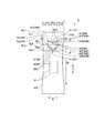
- FIG. 1 is a plan view of the disposable diaper according to the embodiment viewed from the skin surface side.
- FIG. 2 is a plan view of the absorbent core according to the embodiment.
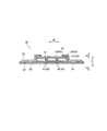
- FIG. 3 is a schematic cross-sectional view taken along the line AA of the disposable diaper shown in FIG.
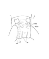
- FIG. 4 is a diagram schematically showing a state in which a wearer wearing a disposable diaper has legs lowered.
- FIG. 5 is a diagram schematically showing the disposable diaper in which the wearer wears the disposable diaper and the leg is raised, and the wearer raises the leg.
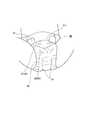
- FIG. 6 is a diagram schematically showing the disposable diaper in a state where the wearer raises the legs and closes the legs.
- FIG. 7 is a schematic cross section along the front-back direction of the disposable diaper in the state which the wearer lowered the leg.
- FIG. 8 is a schematic cross section along the front-back direction of the disposable diaper in the state which the wearer raised the leg.
- FIG. 9 is a plan view showing an absorbent core according to a modified example.
- the disposable diaper which concerns on one aspect has the front-back waist region, the back waist region, and the crotch region arrange
- An absorption core disposed in a region, a fastening tape disposed in the rear waistline region and capable of being fixed to the front waistline region, and a waistline extending along the width direction in the front waistline region and the rear waistline region
- a second virtual line extending in a direction and a third virtual line passing through the centers of the first virtual line and the second virtual line in the front-rear direction and extending in the width direction are set, the deformation base point portion At least a part is provided in the abdominal region between the first virtual line and the third virtual line.
- the inward force in the width direction and the inward force in the width direction are likely to be applied to the front region between the first virtual line and the second virtual line in the front-rear direction.
- the abdominal region which is the front half of the front region, faces the front bulge of the leg, and therefore, when the wearer raises the leg or closes the leg, the abdominal region receives a force to pull the leg forward.
- the wearer closes the legs the wearer is likely to receive a force that is pressed inward in the width direction. Since the girth holding region of the disposable diaper is in close contact with the body, the abdominal region is deformed with the rear end edge of the girth holding region as a base point.
- the absorbent core in the abdominal region is deformed even when the deformation base point portion is set as the base point.
- the deformation base point portion extends outward in the width direction toward the front side and is arranged so as to face the force applied by the movement of the leg. Therefore, the absorbent core in the abdominal region deforms with the deformation base point portion as a base point according to the movement of the leg.
- the front end edge of the deformation base point portion may be separated from the first virtual line in the front-rear direction.
- the deformation base point of the absorbent core can be formed at a position apart from the waistline holding region in the front-rear direction. It is possible to suppress the positional displacement in the waistline holding region and suppress the positional displacement of the entire disposable diaper.
- the deformation base point portion can be provided in the vicinity of the leg-surrounding opening portion where the force of the wearer's leg is likely to act, and the deformation base point corresponding to the movement of the leg is more easily formed.
- the front end edge of the deformation base point portion is It may be located in front of the fourth virtual line.
- the front abdominal region the region between the first imaginary line and the fourth imaginary line
- the absorbent core is easily deformed with the deformation base point portion as a base point when the leg is lifted.
- the front end edge of the deformation base point portion is It may be located behind the fourth imaginary line.
- the force is particularly likely to be applied to the area behind the fourth virtual line.
- the front end edge of the deformation base point portion is located on the rear side of the fourth imaginary line, the absorbent core easily deforms with the deformation base point portion as a base point when the legs are closed. By controlling the deformation when the legs are closed, the deformation easily returns to the original position according to the movement of the legs thereafter, and it is easy to keep the body covered with the absorbent core and suppress the leakage.
- the absorbent core has a pair of side regions located on both sides in the width direction of a region obtained by dividing the entire region of the absorbent core in the width direction into four equal parts.
- the outer edge of the base point may be located in the side region.
- the side region of the absorbent core is located near the leg and is likely to receive the force of the leg. Since the deformation base point portion is located in the side area of the absorbent core, the absorbent core is easily deformed with the deformation base point portion as a base point according to the movement of the leg. Further, the force applied to the deformation base point portion is transmitted along the deformation base point portion on the extension line of the deformation base point portion.
- the deformation base point portion Since the deformation base point portion is located in the side area of the absorbent core, the deformation base point of the deformation base point portion easily reaches the outer edge of the absorbent core. When the deformation base point reaches the outer edge of the absorbent core, the fold line due to the deformation base point is stably formed, and the intended deformed state of the absorbent core is easily maintained.
- the absorbent core has a pair of central regions located on a central side in the width direction among regions obtained by dividing the entire region of the absorbent core in the width direction into four equal parts.
- the inner edge of the part may be located in the central region.
- the force applied to the outer edge of the absorbent core by the movement of the leg can be guided to the center side in the width direction of the absorbent core. Deformation can be controlled over the entire width of the absorbent core, and unintended deformation can be suppressed.
- the length of each deformation base point portion in the width direction may be 1 ⁇ 4 or more of the entire area of the absorbent core in the width direction. According to this aspect, the deformation can be controlled over the entire width direction of the absorbent core, and the unintended deformation can be suppressed.
- the crotch deformation guide portion extends in the front-rear direction across the second virtual line and guides the deformation of the absorbent core in the thickness direction, and the deformation base point portion is the crotch part. It may be arranged on a guide extension line extending from the front end edge of the deformation guide portion to the front side. According to this aspect, the deformation base point portion extends in the width direction, and the deformation extending in the front-rear direction from the crotch deformation guide portion can be separated.
- the absorbent core can be deformed according to the crotch and the abdomen.
- the deformation intersection point where the deformation extension lines extending along the deformation base point portion from the respective deformation base point portions forming the pair of deformation base point portions intersect is located on the front side of the third virtual line.
- the deformation based on each deformation base point portion extends to the crotch side along the deformation extension line, and intersects at the deformation intersection of the pair of deformation extension lines. The region sandwiched by the deformation extension lines is deformed so as to bulge with respect to the body by being sandwiched by both legs.
- the region sandwiched by the deformation extension lines can cover the bulge on the lower side (groin side) than the depression of the lower abdominal portion. Since the deformation intersection is not located on the rear side of the third imaginary line, the deformation that bulges with respect to the body via the deformation base point does not easily reach the crotch, and the absorbability for the crotch is easily secured.
- the front end edge of the deformation base point portion is separated from the first virtual line in the front-rear direction, passing through the center of the first virtual line and the third virtual line in the front-rear direction,
- the deformation intersection may be located on the front side of the fourth imaginary line.
- the front abdominal region the region between the first imaginary line and the fourth imaginary line
- the deformation intersection point becomes the fourth virtual line. It may be located on the rear side with respect to.
- the force that is pressed inward in the width direction is likely to be applied to the region behind the fourth imaginary line. This inward force in the width direction acts not only on the rear abdominal region but also on the rear side of the rear abdominal region.
- the region sandwiched by the deformation extension lines is provided on the rear side of the rear abdomen region, and the deformation of the absorbent core can be controlled even in the region facing the crotch.
- the core intersection point at which the deformation extension line extending from each deformation base point portion along the deformation base point portion and the outer edge of the absorbent core intersect is located rearward of the first virtual line. You can do it.
- the deformation with the deformation base point portion as the base point extends along the deformation extension line and is easily transmitted to the outer edge of the absorbent core. Since the core intersection is located on the rear side of the first imaginary line, the deformation of the absorbent core due to the deformation base point is difficult to be transmitted to the waistline holding region, and the waistline can be maintained.
- the maximum width of the deformation base point portion may be longer than the thickness of the absorbent core in a region close to the deformation base point portion. According to this aspect, it is easy to deform the absorbent core with the deformation base portion as the base point over the entire area in the thickness direction, and it is easier to realize the intended deformation.
- a high-rigidity portion having higher rigidity than a region outside the deformation base point portion in the width direction may be provided between the pair of deformation base point portions.
- the high-rigidity portion since the high-rigidity portion is provided between the deformation base points, a difference in rigidity occurs between a region outside the deformation base point portion in the width direction and a region inside the deformation base point portion, and the deformation occurs. The absorbent core is more easily deformed from the base point.
- the high-rigidity portion makes it difficult for the deformation base point portion to deform, and it is easy to maintain the deformation from the deformation base point portion.
- it becomes difficult for the region between the deformation base point portions to have a width, and the length in the width direction of the region between the pair of deformation base point portions can be secured, and leakage can be suppressed.
- the pair of deformation base point portions may be continuous in the width direction. According to this aspect, when pressed from both sides in the width direction by both legs, the pair of deformation base point portions interfere with each other, and it is easy to maintain the deformation based on the deformation base point portions. In addition, the area between the deformation base point portions does not easily fit into the width, and the length in the width direction of the area between the pair of deformation base point portions can be secured and leakage can be suppressed.
- a stretchable member that expands and contracts in the width direction may be provided outside the front and rear inner ends of the waistline holding region in the front and rear direction.
- the closeness of the waistline holding region to the body can be enhanced, and even if the crotch region moves in the front-rear direction due to the movement of the legs, it is possible to suppress the displacement of the waistline holding region in the front-rear direction. Therefore, even when repeated lifting and lowering operations of the legs are performed, displacement of the entire absorbent core is suppressed, and the absorbent core is deformed based on the deformation base point portion according to the movement of the legs to cover the body. Easy to continue.
- a waist rigidity region having higher rigidity than a region extending rearward from the first virtual line may be provided on the front side of the first virtual line.
- the waist rigid region can suppress deformation of the waistline holding region, the waistline holding region can continuously cover the waist of the wearer, and the abdominal bulge can be continuously covered.
- the pair of deformation base point portions includes a pair of first deformation base point portions and a pair of second deformation base point portions located rearward of the pair of first deformation base point portions. You can do it.
- the absorbent core is deformed with the first deformation base point portion located on the front side as a base point.
- the wearer closes the legs or a force is applied inward in the width direction, the region deformed with the first deformation base point portion as a base point is deformed with the second deformation base point portion as a base point.
- the second deformation base point portion can also control the deformation of the region deformed with the first deformation base point portion as a base point.
- the first angle of the first deformation base point portion with respect to the width direction may be smaller than the second angle of the second deformation base point portion with respect to the width direction.
- the first deformation base point portion located on the front side is more likely to be acted upon by the force that is pulled up to the ventral side than the force that is pressed inward in the width direction.
- the second deformation base point portion located on the rear side is more likely to be acted upon by a force pressed inward in the width direction than the first deformation base point portion.
- the absorbent core is more likely to be deformed with the deformation base point part as a base point, and the deformation of the absorbent core can be controlled more.
- a first deformation extension line extending from the first deformation base point portion along the first deformation base point portion and a second deformation extension extending from the second deformation base point portion along the second deformation base point portion.
- the extension lines may intersect at the outer side in the width direction with respect to the outer edge of the absorbent core.
- the first deformation base point portion and the second deformation base point portion may be separated from each other in the front-rear direction. According to this aspect, it becomes difficult for the deformation caused by the first deformation base point portion and the deformation caused by the second deformation base point portion to interfere with each other, and each can form an independent base point.
- the disposable diaper is a tape type disposable diaper.
- FIG. 1 is a plan view of the disposable diaper 10 according to the present embodiment as viewed from the skin surface side
- FIG. 2 is a plan view of the absorbent core according to the embodiment as viewed from the skin surface side.
- the plan views shown in FIGS. 1 and 2 show the disposable diaper in an expanded state.
- FIG. 3 is a schematic cross-sectional view taken along the line AA of the disposable diaper shown in FIG.
- the stretched state in the present invention is a state in which the disposable diaper 10 is stretched to a state in which wrinkles are not formed.
- the natural state in the present invention means, in the case of the disposable diaper 10 housed in the package, the disposable diaper 10 is taken out from the package, and the atmosphere is kept at 20 ° C. ⁇ 2 ° C. and a relative humidity of 60% ⁇ 5% RH. It is in a state of being left for 24 hours.
- the disposable diaper 10 has a front-back direction L and a width direction W orthogonal to each other.
- the front-back direction L is defined by the direction extending to the front side of the body and the back side of the body.
- the front-rear direction L is a direction that extends in the front-rear direction in the deployed disposable diaper 10.
- the disposable diaper 10 has a thickness direction T orthogonal to both the front-rear direction L and the width direction W.
- the thickness direction T extends to a skin surface side T1 facing the wearer side and a non-skin surface side T2 opposite to the skin surface side.
- the disposable diaper 10 has a front waistline region S1, a back waistline region S2, and a crotch region S3.
- the front waistline region S1 is a region facing the front waistline (abdomen) of the wearer.
- the back waistline region S2 is a region facing the back waistline (back part) of the wearer, and includes a region on which the body (buttock) is placed when worn.
- the crotch region S3 is located in the crotch of the wearer and is a region arranged between the front waistline region S1 and the rear waistline region S2.
- the crotch region S3 is a region in which leg openings 65 arranged around the legs of the wearer are provided.
- the leg openings 65 are portions that are recessed inward in the width direction from the outer edge of the disposable diaper.
- the disposable diaper 10 includes an absorbent core 31 containing an absorbent material.
- the absorbent core 31 may be disposed at least in the crotch region S3, may be disposed in the front waistline region S1, and may be also disposed in the rear waistline region S2.
- the absorbent core 31 comprises an absorbent material such as ground pulp or super absorbent polymer (SAP), or mixtures thereof.
- the absorbent core 31 may be covered by the core wrap 32.
- the absorber 30 may be configured by the absorbent core 31 and the core wrap 32.
- the core wrap 32 may be made of tissue and may be disposed on the skin surface side T1 of the absorbent core 31 and the non-skin surface side T2 of the absorbent core.
- a surface sheet 21 and a side sheet 22 may be provided on the skin side T1 of the absorbent body 30 including the absorbent core 31.
- the topsheet 21 may be disposed across the center of the absorber 30 in the width direction W.
- the side sheet 22 may be arranged so as to cover the outer side portion of the top sheet 21.
- the topsheet 21 and the sidesheets 22 may be made of a liquid-permeable sheet such as a nonwoven fabric or a perforated plastic film.
- the inner portion of the side seat 22 may be folded back and overlapped.
- a leak-proof stretchable portion 43 that stretches in the front-rear direction L may be provided between the overlapping side seats 22.
- the leak-proof stretchable portion 43 may be made of rubber thread that stretches in the front-rear direction L.
- the side sheet 22 and the leak-proof stretchable portion 43 constitute a leak-proof gather that stands up on the skin surface side T1 when worn.
- the back sheet 23 and the exterior sheet 24 may be provided on the non-skin surface side T2 of the absorber 30.
- the exterior sheet 24 may be provided on the non-skin surface side T2 of the back sheet 23.
- the length of the back sheet 23 in the width direction W is shorter than the length of the exterior sheet 24 in the width direction W, and the length of the back sheet 23 in the front-rear direction L is shorter than the length of the exterior sheet 24 in the front-rear direction L.
- the back sheet 23 may be made of a liquid impermeable film.
- the exterior sheet 24 may be made of a liquid-permeable nonwoven fabric.
- Fastening tape 91 is provided in the rear waistline area S2.
- the fastening tape 91 is arranged in the rear waistline region S2 and can be fixed to the front waistline region S1.
- the fastening tape 91 has a base portion 92 and a locking portion 93.
- the base portion 92 is arranged between the exterior sheet 24 and the side sheet 22 in the thickness direction T, and extends outward from the exterior sheet 24 and the side sheet 22 in the width direction W.
- the locking portion 93 is disposed on the base portion 92 and may engage with the target portion 95.
- the target portions 95 are arranged at intervals in the width direction W in the front waistline region S1, and are configured such that the fastening tapes 91 are fixed to each other.
- the disposable diaper may not include the target portion, and the locking portion 93 may be fixed to the exterior sheet in the front waistline region.
- the disposable diaper has a waistline holding region 60.
- the waistline holding region 60 is a region that is in close contact with the wearer's waistline in a worn state, and is a region that extends in the width direction W from the fastening portion 93 of the fastening tape.
- the waistline holding region 60 in the rear waistline region S2 is a region extending in the width direction W from the locking portion 93 of the fastening tape 91.
- the waistline holding region 60 in the front waistline region S1 and the waistline holding region 60 in the rear waistline region pass through the center of the disposable diaper in the front-rear direction and extend in the width direction W in the front-rear centerline (second virtual line described below) 10LC. It becomes line symmetric with respect to.
- the distance between the front end edge of the waistline holding region 60 and the front-rear centerline 10LC in the front waistline region S1 matches the distance between the front end edge of the waistline holding region 60 and the front-rear centerline 10LC in the rear waistline region S2.
- the waistline holding region is shown by hatching.
- the disposable diaper 10 may have a leg elastic part 42 that expands and contracts in the front-rear direction outside the absorbent core 31 in the width direction W.
- the leg stretchable portion 42 may be provided between the side sheet 22 and the back sheet 23, and between the side sheet 22 and the exterior sheet 24.
- the leg stretchable portion 42 is configured by a belt-shaped stretchable sheet that stretches in the front-rear direction L. Due to the contraction of the leg elastic part 42, the leg opening of the disposable diaper 10 fits around the leg when worn.
- the disposable diaper 10 may have a waist elastic part 45 extending in the width direction W along the rear edge of the disposable diaper.
- the waist elastic part 45 constitutes the elastic member of the present invention.
- the waist elastic part 45 may be provided between the back sheet 23 and the exterior sheet 24, between the top sheet 21 and the exterior sheet 24, and between the side sheet 22 and the exterior sheet 24.
- the rear end edge of the waist elastic part 45 may be located in front of the rear edge of the disposable diaper, and the front end edge of the waist elastic part 45 may be located in front of the rear edge of the absorbent core 31.
- the waist elastic part 45 may extend outside the absorbent core 31 in the width direction W.
- the waist elastic part 45 is configured by a belt-shaped elastic sheet that expands and contracts in the width direction W.
- the disposable diaper 10 may have a pair of crotch elastic portions 41 provided in a region of the crotch region that overlaps with the absorbent core 31.
- the crotch elastic part 41 may form the crotch deformation guide part 85 of the present invention.
- the crotch elastic part 41 may be arranged on the non-skin surface side of the absorber 30.
- the crotch stretchable portion 41 may be arranged between the absorbent core 31 and the back sheet 23, or may be provided between the core wrap 32 arranged on the non-skin surface side T2 of the absorbent core 31 and the back sheet 23. Alternatively, it may be provided between the back sheet 23 and the exterior sheet 24.
- the crotch stretchable portion 41 of the present embodiment is arranged between the back sheet 23 and the exterior sheet 24.
- the crotch stretchable portions 41 extend in the front-rear direction L and are arranged at intervals in the width direction W.
- the crotch stretchable portions 41 are not arranged at the center of the absorbent core 31 in the width direction W, but two at each side of the absorbent core 31 with respect to the center of the absorbent core 31 in the width direction W.
- the crotch stretchable portion 41 is made of rubber thread arranged along the front-rear direction L.
- the crotch elastic part 41 may be configured by a belt-shaped elastic sheet that stretches in the front-back direction, may be configured by one thread rubber, or may be configured by three or more thread rubbers. It may be configured.
- the inseam stretchable portion 41 may straddle the front-rear centerline 10LC. By contracting the crotch elastic part 41, the front-rear centerline 10LC can be pulled up to the body side.
- the crotch stretchable portion 41 may be arranged only on the front side of the front-rear centerline 10LC without straddling the front-rear centerline 10LC, or only on the rear side of the front-rear centerline 10LC. It may be arranged in.
- At least a part of the crotch elastic part 41 is located inside the outer edge of the absorbent core 31 in the width direction W in the narrow part 35 described later. At least a part of the crotch stretchable portion 41 is arranged within the narrow portion 35 in the front-rear direction. The rear end edge of the crotch stretchable portion 41 is arranged in front of the rear end edge of the narrow portion 35. Further, the front end edge of the crotch stretchable portion 41 may be arranged rearward of the front end edge of the narrow portion 35.
- the absorbent core 31 in the crotch region S3 is pulled up to the body side by the contraction of the crotch elastic part 41.
- a pair of inseam stretchable portions 41 are located on both outer sides of the center in the width direction W, and a region that overlaps with the inseam stretchable portion 41 is pulled up by contraction of the inseam stretchable portion 41, and is sandwiched by the left and right inseam stretchable portions 41. Is pulled up while maintaining a flat shape along the body.
- the pair of crotch stretchable portions 41 are located inside the outer edge 31E of the absorbent core 31 in the width direction W, and the region located between the pair of crotch stretchable portions 41 is more widthwise W than the pair of crotch stretchable portions 41.
- the center of the absorbent core in the width direction W is deformed into a convex shape with the side portion as a base point, and the fit property to the crotch of the body can be secured.
- the stretchable portion including the leg stretchable portion 42, the leak-proof stretchable portion 43, the waist stretchable portion 45, and the crotch stretchable portion 41 in the present invention are arranged in a state in which an elastic member such as a rubber thread or a stretchable sheet can stretch. It does not include a portion in which the elastic member is arranged in a non-expandable state. That is, the stretchable portion is the effective length portion of the elastic member that constitutes the stretchable portion.
- the crotch stretchable portion 41 may be arranged only on the front side of the front-rear centerline 10LC without straddling the front-rear centerline 10LC, or only on the rear side of the front-rear centerline 10LC. It may be arranged in.
- the outer side portion in the present invention is a portion occupying a certain range in the width direction W including the outer side edge in the width direction W, and the outer side edge is the outer side edge in the width direction W.
- the inner side portion is a portion that occupies a certain range in the width direction W including the inner side edge in the width direction W, and the inner side edge is the inner side edge in the width direction W.
- the outer edge is an outer edge in the front-rear direction
- the inner edge is an inner edge in the front-rear direction.
- the overlapping state is a state in which one member and the other member are overlapped in a plan view, and the other member is arranged on the skin surface side or the non-skin surface side of the one member. It is in a state of being.
- the overlapping state includes not only a state in which one member and the other member are in contact with each other, but also a configuration in which another member is interposed between the one member and the other member.
- the disposable diaper 10 has a front region R10 and an abdominal region R20.
- the front region R10 and the abdomen region R20 are provided between the waistline holding region 60 and the front-rear centerline 10LC.
- a first virtual line VL1 passing through the rear end edge of the waistline holding region 60 in the front waistline region and extending in the width direction W
- a second virtual line VL2 passing through the center of the disposable diaper in the front-rear direction and extending in the width direction W
- a third virtual line VL3 passing through the center of the first virtual line VL1 and the second virtual line VL2 in the front-rear direction L and extending in the width direction W
- a center of the first virtual line VL1 and the third virtual line VL3 in the front-rear direction L and a center of the first virtual line VL1 and the third virtual line VL3 in the front-rear direction L.
- the front region R10 is a region between the first virtual line VL1 and the second virtual line VL2.
- the second virtual line VL2 matches the front-rear centerline 10LC.
- the abdominal region R20 is a region between the first virtual line VL1 and the third virtual line VL3.
- the abdominal region R20 is the front half region of the front region R10.
- the abdominal region R20 has a front abdominal region R21 and a rear abdominal region R22.
- the front abdomen region R21 is a front half region of the abdomen region R20 and is a region between the first virtual line VL1 and the fourth virtual line VL4.
- the rear abdominal region R22 is a rear half region of the abdominal region R20, and is a region between the third virtual line VL3 and the fourth virtual line VL4.
- the disposable diaper according to the present invention is configured to control the deformation of the absorbent core in the front region R10 when the wearer moves the leg. The deformation mode when worn will be described in detail later.
- the absorbent core 31 has a region obtained by dividing the entire region of the absorbent core in the width direction W into four equal parts.
- the four-divided region has a pair of side regions 31S located on both sides in the width direction W and a pair of central regions 31C.
- the pair of central regions 31C are arranged on both sides of the center of the absorbent core in the width direction W.
- the pair of side regions 31S are arranged on both sides of the central region 31C in the width direction W.
- the absorbent core 31 has a narrow portion 35 whose length in the width direction W is shorter than the maximum width 31M of the absorbent core 31, and a wide portion arranged outside the narrow portion 35 in the front-rear direction.
- the narrow portion 35 is arranged between the wide portions arranged at the front and rear.
- the length of the narrow portion 35 in the width direction W increases toward the outside in the front-rear direction L.
- the shape of the absorbent core 31 in plan view is an hourglass shape.
- the shape of the absorbent body including the core wrap may be an hourglass shape.
- the absorbent core 31 may have a low basis weight portion 33 in which the basis weight of the absorbent material is lower than the surrounding area.
- the low basis weight portion 33 may constitute the crotch deformation guide portion 85 of the present invention.
- the low grammage portion 33 is provided along the front-rear direction L.
- the low basis weight portion 33 may extend in the front-rear direction L, may be parallel to the front-rear direction L, or may be inclined at an angle of less than 90 degrees with respect to the front-rear direction L.
- the low basis weight portion 33 is a portion where the basis weight of the absorbent material is lower than that of the surrounding absorbent core 31, is thinner than the surrounding absorbent core 31, and has low rigidity. Therefore, the low grammage portion 33 is likely to become a deformation base point in the mounted state. A deformation base point that extends in the front-rear direction in the worn state is easily formed on the absorbent core 31.
- the low grammage portion 33 may be a portion where the grammage of the absorbent material is substantially zero (the grammage of design is 0, but includes a portion where the surrounding absorbent material is mixed), or the surrounding area. It may be a portion where the absorbent material having a smaller basis weight is arranged.
- the low basis weight portion 33 may be a slit having a constant length in the width direction W, or may be a notch in which the length in the width direction W is practically zero.
- the length of each low basis weight portion 33 in the width direction W may be 2 mm or more and 10 mm or less, and more preferably the thickness of the absorbent core 31 or more and 8 mm or less. Since the length of the low basis weight portion 33 in the width direction W is equal to or greater than the thickness of the absorbent core 31, the absorbent core 31 is easily deformed in the thickness direction with the low basis weight portion 33 as a base point.
- the length of the low basis weight portion 33 in the width direction W is 8 mm or less, it is possible to suppress the anxiety about the absorption performance due to the long length of the low basis weight portion 33 in the width direction W.
- the length of 33 in the front-rear direction L may be 30 mm or more and 180 mm or less.
- the low basis weight portions 33 are arranged in a pair in the width direction W at intervals.
- the low grammage portion 33 is provided in the central region 31C.
- the low grammage portions 33 may be arranged at intervals in the width direction W on both sides of the width center line 10WC passing through the center of the disposable diaper in the width direction and extending in the front-rear direction.
- the center of the low basis weight portion 33 in the front-rear direction may be arranged rearward of the front-rear centerline 10LC.
- the front edge 33F of the low basis weight portion 33 may be located in front of the front edge of the crotch elastic portion 41, and the rear edge 33R of the low basis weight portion 33 matches the rear edge of the crotch elastic portion 41 or It may be located in front of the rear edge.
- the outer edge of the low basis weight portion 33 may be aligned with the thread rubber located outside the width direction W in the thread rubber forming the crotch stretchable portion 41 in the width direction W, and the inner edge of the low basis weight portion 33.
- In the width direction W may match the thread rubber that is positioned inside the width direction W among the thread rubber that forms the crotch stretchable portion 41.
- the low basis weight portion 33 may be arranged in a region overlapping with the crotch stretchable portion 41.
- the absorbent core 31 is deformed with a low basis weight portion extending in the front-rear direction when worn as a base point. Therefore, due to the contraction of the crotch stretchable portion 41, the absorbent core 31 is easily deformed by the convex shape toward the body side, and the absorbent core 31 can be properly accommodated in the crotch of the wearer.
- the low grammage portion 33 which serves as a deformation starting point of the absorbent core 31, has a grammage lower than that of the surrounding region, can suppress the thickness even after absorbing body fluid, and can maintain a deformed state.
- the measurement of the “basis weight of the absorbent core” in this specification shall be performed by the following measuring method.
- a sample taken out from the package and left in that state for 12 hours in an atmosphere of 20 ° C. ⁇ 2 ° C. and a relative humidity of 60% ⁇ 5% RH is used.
- the packaging sheet is opened and the folded disposable diaper is developed.
- the part for measuring the basis weight is cut out from the disposable diaper, and the part other than the absorbent core such as the topsheet is removed from the cut out part.
- the area and weight of the portion for measuring the basis weight of the absorbent core are measured. The basis weight is calculated based on the weight and the area.
- the absorbent core 31 may be provided with a pair of deformation base points 80.
- the deformation base point portions 80 extend outward in the width direction W toward the front side, and are arranged in a pair in the width direction W at intervals.
- the pair of deformation base points 80 may be line-symmetric with respect to the width center line 10WC.
- the deformation base point portion 80 may be the deformation base point of the absorbent core 31, and the embossed portion obtained by compressing the absorbent core in the thickness direction, the low basic weight portion in which the basic weight of the absorbent material is lower than the surroundings, and the absorbent material are arranged.
- the slit may be formed by at least one of a slit and a cut portion obtained by cutting the absorbent core in the thickness direction.
- the deformation base point portion 80 has a base point edge 80G that is an edge of the deformation base point.
- the base point edge is an edge at which a polygonal line of the thickness of the absorbent core 31 is formed.
- the base point edge 80G of the present embodiment is an edge extending in the width direction W at the deformation base point portion 80.
- FIG. 4 is a diagram schematically showing a state in which a wearer wearing a disposable diaper has legs lowered.
- FIG. 5 is the figure which showed typically the state which the wearer wearing the disposable diaper raised the leg.
- FIG. 6 is a diagram schematically showing a state in which a wearer wearing a disposable diaper lifts his legs and closes his legs.
- FIG. 7 is a schematic cross section along the front-back direction of the disposable diaper in the state which the wearer lowered the leg.
- FIG. 8 is a schematic cross section along the front-back direction of the disposable diaper in the state which the wearer raised the leg. 7 and 8 show only the line of the entire disposable diaper, the deformation base point portion 80, and the fastening tape for convenience of description, and other members are omitted.
- BL shown in Drawing 7 and Drawing 8 shows a line of a wearer's body.
- the disposable diaper of the present invention is configured so that the deformation of the absorbent core 31 in the front region R10 is controlled by the deformation base point portion 80.
- a recess extending in the width direction W is generally formed at the lower end of the abdomen.
- the recess at the lower end of the abdomen is curved upward from the center in the width direction W toward the outside in the width direction W, and is particularly easily formed particularly in an infant.
- the fastening tape is generally fastened in a position opposite the bulge of the wearer so that the disposable diaper can cover the bulge of the wearer's abdomen.
- the leg openings 65 in the front waistline region S1 and the back waistline region S2 are arranged so as to surround the wearer's legs.
- the wearer's legs are generally separated from the outer edge of the absorbent core 31, and the absorbent core 31 has an inner side in the width direction W. It is in a state where no force is applied to the inside or a slight force toward the inside in the width direction W is applied.
- the disposable diaper is arranged along the bulge of the abdomen and the recess of the lower end of the abdomen.
- the front region R10 is in a state in which no force is applied to the abdominal side by the legs or a slight force is applied to the anterior region.
- the inward force in the width direction W and the inward force in the width direction W are likely to be applied to the front region R10.
- the abdomen region R20 which is the front half of the front region R10, faces the front part of the leg that bulges toward the front side, the force that is pulled up to the front side when the wearer raises the leg or closes the leg.
- the force of being pressed inward in the width direction W is also likely to be received.
- the front region R10 is deformed with the rear end edge of the waistline holding region 60 as a base point.
- the deformation base point portion 80 is provided in at least a part of the abdomen region R20 in the front region R10, and the absorbent core of the abdomen region R20 deforms with the deformation base point portion 80 as a base point.
- the deformation base point portion 80 extends outward in the width direction W toward the front side and is arranged so as to face the force applied by the movement of the leg. Therefore, the absorbent core 31 in the abdomen region R20 deforms with the deformation base point portion 80 as a base point.
- the base point edge 80G of the deformation base point portion 80 may extend outward in the width direction W toward the front side.
- the base edge 80G of each deformation base point 80 may extend outward in the width direction W toward the front side.
- the extension line connecting the base point portions constitutes the base point edge.
- the base point edge 80G may be linear as in the present embodiment, or may be curved.
- the deformation base point portion 80 may be provided at least in part in the abdominal region R20, may be provided only in the abdominal region R20, may extend from the abdominal region R20 to the front side, or the abdomen. It may extend from the region R20 to the rear side.
- the front end edge 80F of the deformation base point portion 80 may be separated from the first virtual line VL1 in the front-rear direction L. That is, the deformation base point portion 80 may be provided only on the rear side of the first imaginary line VL1 and may be provided so as not to overlap the waistline holding region 60. According to this configuration, the deformation base point of the absorbent core 31 can be formed at a position separated from the waistline holding region 60 in the front-rear direction L. The position shift of the waistline holding region 60 can be suppressed, and the position shift of the entire disposable diaper can be suppressed. In addition, the deformation base point portion 80 can be provided in the vicinity of the crotch of the wearer, and the deformation base point corresponding to the movement of the leg is more easily formed.
- the front end edge 80F of the deformation base point portion 80 may be located in front of the fourth virtual line VL4.
- the first deformation base point portion 81 as the deformation base point portion 80 is arranged, and the front end edge 81F of the first deformation base point portion 81 is arranged.
- the pair of first deformation base point portions 81 may be separated in the width direction and may be separated from the width center line 10WC.
- the first deformation base point portion 81 may be separated from the outer edge of the absorbent core.
- the absorbent core is easily deformed with the deformation base point portion 80 as a base point when the leg is lifted.
- the front end edge 80F of the deformation base point portion 80 may be located on the rear side of the fourth virtual line VL4.
- the second deformation base point portion 82 as the deformation base point portion 80 is arranged, and the front end edge 82F of the second deformation base point portion 82 is arranged.
- the pair of second deformation base point portions 82 may be separated in the width direction and may be separated from the width center line 10WC.
- the second deformation base point portion 82 may be separated from the outer edge of the absorbent core.
- the absorbent core is easily deformed with the deformation base point portion 80 as a base point when the legs are closed.
- the deformation easily returns to the original position according to the movement of the legs thereafter, and it is easy to keep the body covered with the absorbent core and suppress the leakage.
- the rear end edge 80R of the deformation base point portion 80 may be on the front side of the second virtual line VL2, and more preferably on the front side of the third virtual line VL3.
- the second virtual line VL2 and a region in the vicinity of the second virtual line VL2 in the front-rear direction are likely to be guided by the excrement from the excretion port, and are preferably arranged facing the excretion port. Since the rear end edge 80R of the deformation base point portion 80 is located on the front side of the third virtual line VL3, the absorbent core can be disposed so as to face the excretory opening and ensure the absorbent performance.
- the deformation base point portion 80 may include a first deformation base point portion 81 and a second deformation base point portion 82.
- the absorbent core 31 is deformed with the first deformation base point portion 81 located on the front side as a base point.
- FIG. 6 when the wearer applies a force toward the inner side in the width direction W by closing the legs or the like, the region deformed with the first deformation base point portion 81 as a base point has the second deformation base point portion 82 as a base point. Transforms into.
- the first deformation base point portion 81 when the first deformation base point portion 81 is deformed with respect to the base point and further pressed from the crotch region side to the front side, the first deformation base point portion 81 is already the deformation base point, and therefore moves to the front side. Instead, the region on the rear side of the first deformation base point portion 81 swells in the direction away from the wearer (see FIG. 8). At this time, since the second deformation base point portion 82 is on the rear side of the first deformation base point portion 81, the deformation base point by the second deformation base point portion 82 is further formed in the region bulging in the direction away from the wearer. It is also possible to control the deformation of the area that bulges away from the wearer. As shown in FIG.
- the second deformation base point portion 82 moves toward the wearer side from the first deformation base point portion 81 side toward the second deformation base point portion 82 side. And the deformation that bulges toward the wearer from the second virtual line side toward the second deformation base point portion 82 side.
- the deformation having the second deformation base point portion 82 as the apex can be supported, and the deformed state can be easily maintained.
- the second deformation base point portion 82 can also control the deformation of the region deformed with the first deformation base point portion 81 as the base point.
- the first angle ⁇ of the first deformation base point portion 81 with respect to the width direction W may be smaller than the second angle ⁇ of the second deformation base point portion 82 with respect to the width direction W.
- the first deformation base point portion 81 is more likely to be acted on by the abdomen than the force pressed inward in the width direction W, and the second deformation base point portion 82 is wider than the first deformation base point portion 81 in the width direction W.
- the force of being pressed inward is easy to act.
- the absorption core is more easily deformed with the deformation base point portion as the base point, and the deformation of the absorption core can be controlled more.
- the first deformation base point portion 81 and the second deformation base point portion 82 may be separated in the front-rear direction L. According to this configuration, it becomes difficult for the deformation by the first deformation base point portion 81 and the deformation by the second deformation base point portion 82 to interfere with each other, and each can form an independent base point.
- a first deformation extension line EL1 extending from the first deformation base point portion 81 along the first deformation base point portion 81 and a second deformation extension line extending from the second deformation base point portion 82 along the second deformation base point portion 82.
- the extension line EL2 may intersect outside the outer edge 31E of the absorbent core in the width direction W. That is, the first deformation extension line EL1 and the second deformation extension line EL2 do not intersect inside the outer edge 31E of the absorbent core 31 in the width direction W.
- the first deformation extension line EL1 and the second deformation extension line EL2 are lines extending along the base point edge 80G.
- the deformation by the first deformation base point portion 81 and the deformation by the second deformation base point portion 82 can be released to the outer edge 31E of the absorbent core. It becomes difficult for the deformation by the first deformation base point portion 81 and the deformation by the second deformation base point portion 82 to interfere with each other, and it becomes easy to realize the deformation state with each of them as the base point.
- the outer edge 80E of the deformation base point portion 80 may be located in the side area.
- the outer edge 81E of the first deformation base point portion 81 of the present embodiment is located in the side area 31S
- the outer edge 82E of the second deformation base point portion 82 is located in the central area 31C.
- the side region 31S is located near the leg and is likely to receive the force of the leg. Since the deformation base point portion is located in the side area of the absorbent core, the absorbent core is easily deformed with the deformation base point portion as a base point according to the movement of the leg. Further, the force applied to the deformation base point portion is transmitted along the deformation base point portion on the extension line of the deformation base point portion.
- the deformation base point of the deformation base point portion easily reaches the outer edge of the absorbent core.
- the deformation base point is stabilized, and the intended deformed state of the absorbent core is easily maintained.
- the outer edge 80E of the deformation base point portion 80 may reach the outer edge of the absorbent core or may be separated from the outer edge of the absorbent core.
- the outer edge of the deformation starting point may be separated from the outer edge of the absorbent core. It is possible to suppress the force of the leg from being directly transmitted to the deformation base point portion and prevent the absorbent core from being excessively deformed with the deformation base point portion as a base point.
- the inner edge 80I of the deformation base point portion 80 may be located in the central region 31C.
- the inner edge 81I of the first deformation base point portion 81 and the inner edge 82I of the second deformation base point portion 82 of the present embodiment are located in the central region 31C.
- the length of each deformation base point portion in the width direction W may be 1 ⁇ 4 or more of the entire width direction W of the absorbent core 31.
- the length in the width direction W of each deformation base point portion is the length in the width direction W of each deformation base point portion that configures the pair of deformation base point portions, and for example, each length that configures the pair of first deformation base point portions 81.
- This is the length of the first deformation base point portion 81 in the width direction W. Therefore, the length of the pair of deformation base points in the width direction W is 1/2 or more of the entire area of the absorbent core 31 in the width direction W. According to this configuration, since the deformation base point portion is arranged in half or more of the entire area of the absorbent core 31 in the width direction W, the deformation can be controlled over the entire absorbent core 31, and unintended deformation can be suppressed.
- the disposable diaper may have a crotch deformation guide portion 85 that extends in the front-rear direction L across the second virtual line VL2 and guides the deformation of the absorbent core in the thickness direction.
- a crotch deformation guide portion 85 that extends in the front-rear direction L across the second virtual line VL2 and guides the deformation of the absorbent core in the thickness direction.
- the crotch deformation guide portion 85 includes a low basis weight portion having a low basis weight of the absorbent material, an embossed portion obtained by compressing the absorbent core and the like in the thickness direction, and an elastic member arranged to overlap the absorbent core in the thickness direction.
- the crotch deformation guide portion 85 of the present embodiment includes the low basis weight portion 33 formed in the absorbent core 31 and the crotch stretchable portion 41 arranged on the non-skin surface side T2 with respect to the absorbent core. It is composed by.
- the deformation base point portion 80 may be arranged on a guide extension line EL3 extending from the front end edge of the crotch deformation guide portion 85 to the front side.
- the deformation base point portion 80 extends in the width direction W and can divide the deformation extending from the crotch deformation guide portion 85 in the front-rear direction L.
- the absorbent core can be deformed according to the crotch and the abdomen.
- the deformation intersection point P1 between the deformation extension lines extending along the deformation base point portion from each of the deformation base point portions forming the pair of deformation base point portions may be located in front of the third virtual line VL3.
- the deformation extension line extending from each deformation base point portion along the deformation base point portion extends inward in the width direction W from the deformation base point portion toward the rear side.
- the deformation intersection P1 is an intersection where the deformation extension lines in the pair of deformation base points intersect with each other, and is located rearward of the deformation base points.
- the deformation intersection P1 is located on the width center line 10WC when the pair of deformation base points are line-symmetric with respect to the width center line 10WC.
- the deformation intersection P11 between the first deformation extension lines EL1 is located on the front side of the third virtual line VL3, and the deformation between the second deformation extension lines EL2.
- the intersection P12 is located behind the third virtual line VL3.
- the deformation with each deformation base point as the base point extends to the crotch side along the deformation extension line and intersects at the deformation intersection point P1.
- the region sandwiched by the deformation extension lines is deformed so as to bulge with respect to the body by being sandwiched by both legs. As shown in FIG. 8, when the first deformation base point portion 81 is located in the vicinity of the depression of the lower abdomen, the region sandwiched by the deformation extension lines covers the bulge on the lower side (groin side) than the depression of the lower abdominal portion.
- the deformation intersection point P1 is not located on the rear side of the third virtual line VL3, the deformation that bulges with respect to the body from the deformation base point portion 80 as the base point does not easily reach the crotch and the absorbability for the crotch is easily secured.
- the deformation intersection P1 may be located in front of the fourth virtual line VL4.
- the deformation intersection P11 of the first deformation base point portion 81 is located on the front side of the fourth virtual line VL4, and the front edge 81F of the first deformation base point portion 81 is separated from the first virtual line VL1. is doing. Therefore, the inclination of the first deformation base point portion 81 with respect to the width direction W becomes gentle.
- the front abdominal region R21 is likely to receive a force that is pulled up to the abdominal side when the wearer raises his legs.
- the deformation intersection P1 may be located on the rear side of the fourth virtual line.
- the deformation intersection P12 of the second deformation base point portion 82 is located behind the fourth virtual line VL4.
- the rear abdomen region is likely to receive a force that is pressed inward in the width direction W when the wearer closes the legs. This inward force in the width direction W acts not only on the rear abdominal region but also on the rear side of the rear abdominal region.
- the region sandwiched by the deformation extension lines is provided on the rear side of the rear abdomen region, and the deformation of the absorbent core can be controlled even in the region facing the crotch.
- the core intersection point P2 at which the deformation extension line extending from each deformation base point portion along the deformation base point portion and the outer edge of the absorbent core intersect may be located behind the first virtual line VL1. That is, the core intersection point P2 may be separated from the first virtual line VL1.
- P22 and P22 are located behind the first virtual line VL1.
- the deformation based on the deformation base point portion 80 extends along the deformation extension line and is easily transmitted to the outer edge 31E of the absorbent core 31. Since the core intersection is located on the rear side of the first virtual line VL1, the deformation of the absorbent core 31 by the deformation base point portion 80 is difficult to be transmitted to the waistline holding region 60, and the state of holding the waistline can be maintained.
- the maximum width TM of the deformation base point portion 80 is longer than the thickness of the absorbent core 31 in the region close to the deformation base point portion 80.
- the width of the deformation base point portion 80 is the length in the direction orthogonal to the direction in which the deformation base point portion 80 extends, and shows the maximum width TM of the deformation base point portion 80 in FIG. 2. Since the maximum width TM of the deformation base point portion 80 is thicker than the thickness of the absorbent core 31, the absorbent core 31 is likely to be deformed with the deformation base point portion 80 as a base point over the entire area in the thickness direction T, and it is easier to realize the intended deformation. Become.
- the portion where the width of the deformation base point portion 80 is longer than the thickness of the absorbent core 31 occupies more than half of the deformation base point portion 80. Is preferred.
- the entire area of the absorbent core 31 in the thickness direction T is likely to be deformed in a portion of the deformation base point portion 80 which is half or more.
- An elastic member that expands and contracts in the width direction W may be provided outside the inner end edge of the waistline holding region 60 in the front-rear direction L in the front-rear direction L.
- An inner edge of the waistline holding region 60 in the front-rear direction L includes a rear edge of the waistline holding region 60 in the front waistline region S1 and a front edge of the waistline holding region 60 in the rear waistline region S2.
- the waist elastic part 45 as an elastic member is arranged on the rear side of the waistline holding region 60 in the rear waistline region S2, behind the front end edge.
- the waist elastic part 45 as the elastic member may be disposed at least in an area outside the front and rear direction L of the inner peripheral edge of the waist peripheral holding area 60 in the front and rear direction L. It may be arranged inside the front and rear direction L rather than the inner end edge in the front and rear direction L of the waistline holding region 60 across the inner end edge in the direction L.
- Adhesion of the waistline holding region 60 to the body is enhanced by the waistline stretching portion 45, and even if the crotch region S3 moves in the front-rear direction L due to the movement of the legs, displacement of the waistline holding region 60 in the front-rear direction L can be suppressed. Therefore, even when repeated lifting and lowering operations of the legs are performed, displacement of the entire absorbent core is suppressed, and the absorbent core is deformed based on the deformation base point portion according to the movement of the legs to cover the body. Easy to continue.
- a waist rigidity region having higher rigidity than a region extending from the first virtual line VL1 to the rear side may be provided in front of the first virtual line VL1.
- the region extending rearward from the first virtual line VL1 is a region adjacent to the first virtual line VL1 and extending rearward from the first virtual line VL1.
- the waist rigidity region is a region in which the target portion 95 is arranged, and the rigidity of the waist rigidity region is greater than the rigidity of the region from the first virtual line VL1 to the front end edge of the first deformation base point portion 81. Is also high.
- the waist rigid region may be a region where materials such as the target portion 95 are arranged, or a region where the embossed portion of the absorbent core 31 is provided. The waist rigid region suppresses deformation of the waistline holding region, the waistline holding region can continuously cover the waist of the wearer, and the abdominal bulge can be continuously covered.
- “Bending rigidity” in the present specification may be a value measured by Gurley stiffness.
- Gurley stiffness can be measured using a No. 311 Gurley type flexibility tester manufactured by Yasuda Seiki Seisakusho Co., Ltd. according to JIS-L1096.
- the length of the sample in the Gurley stiffness measurement in the width direction W can be 30 mm, and the length in the front-rear direction L can be 25 mm.
- FIG. 9 schematically shows an absorbent core according to a modified example.
- the absorbent core 31A according to Modification 1 includes a pair of deformation base point portions 80A and a high-rigidity portion 87 provided between the pair of deformation base point portions 80A.
- the high-rigidity portion 87 is a region having higher bending rigidity than the surrounding region.
- the high-rigidity portion 87 may be a portion having a higher basis weight than the surrounding area, or may be a portion in which the absorbent core 31 is compressed in the thickness direction.
- the deformation base point portion 80A and the high-rigidity portion 87 according to Modification Example 1 are configured by an embossed portion obtained by compressing the absorbent core 31.
- the high-rigidity portion 87 may be separated from the outer edge of the absorbent core, and may be provided only inside the deformation base point portion 80A in the width direction.
- the rigidity of the high-rigidity portion 87 is higher than the rigidity of the region outside the deformation base point portion 80A in the width direction W. Since the high-rigidity portion 87 is provided between the deformation base point portions 80A, a rigidity difference occurs between an area outside the deformation base point portion 80A in the width direction W and an area inside the deformation base point portion 80A, and the deformation base point The absorbent core is more likely to be deformed with the portion 80A as the base point. Further, the high-rigidity portion makes it difficult for the deformation base point portion 80A to deform, and it is easy to maintain the deformation with the deformation base point portion 80A as the base point. In addition, it becomes difficult for the region between the deformation base point portions 80A to have a width, and the length in the width direction W of the region between the pair of deformation base point portions 80A can be secured and leakage can be suppressed.
- the high rigidity portion 87 may be separated from the deformation base point portion 80A in the width direction W, or may be adjacent to the deformation base point portion 80A in the width direction W.
- the region outside the deformation base point portion 80A in the width direction W is more likely to be deformed than the region between the deformation base point portions 80A, and the difference in rigidity is This makes the absorbent core easier to deform.
- the high rigidity portion and the deformation starting point portion 80A may be integrated.
- the deformation base point portion 80A includes a region extending from the base edge 80G to the thickness of the absorbent core 31 inward in the direction perpendicular to the line along the base edge. I'm out.
- FIG. 9B is a plan view of the absorbent core 31B according to the second modification.
- the modification base point portions 80B according to Modification Example 2 are continuous in the width direction W. That is, the inner edges of the respective deformation base point portions 80B forming the pair of deformation base point portions 80B communicate with each other. According to this configuration, when the legs are pressed from both sides in the width direction W, the pair of deformation base points 80B interfere with each other, and it is easy to maintain the deformation based on the deformation base points 80B. In addition, it becomes difficult for the region between the deformation base point portions 80B to have a width, and the length in the width direction W of the region between the pair of deformation base point portions 80B can be secured, and leakage can be suppressed.
- the first deformation base point portion 81 is continuous in the width direction W, and the second deformation base point portion 82. Is preferably not continuous in the width direction W.
- the second deformation base point portion 82 is located on the crotch side, and a relatively inward force in the width direction W is applied when the legs are closed. Therefore, if the second deformation base point portions 82 are connected to each other, the deformation base point of the second deformation base point portion 82 may be stretched against the movement of the leg inward in the width direction W, which may cause discomfort. Since the second deformation base point portions 82 are separated from each other in the width direction W, the region between the second deformation base point portions 82 is flexibly deformed, thereby not hindering the movement of the leg when the leg is closed, It is possible to suppress discomfort.
- a disposable diaper capable of appropriately covering the wearer's body by deforming the absorbent core along the buttocks and crotch of the body.
Landscapes
- Health & Medical Sciences (AREA)
- Epidemiology (AREA)
- Engineering & Computer Science (AREA)
- Biomedical Technology (AREA)
- Heart & Thoracic Surgery (AREA)
- Vascular Medicine (AREA)
- Life Sciences & Earth Sciences (AREA)
- Animal Behavior & Ethology (AREA)
- General Health & Medical Sciences (AREA)
- Public Health (AREA)
- Veterinary Medicine (AREA)
- Absorbent Articles And Supports Therefor (AREA)
Abstract
脚の動きに応じた吸収コアの変形をコントロールし、吸収コアによって身体を覆い続けることができる使い捨ておむつを提供する。使い捨ておむつ(10)は、吸収コア(31)と、後胴回り域に配置されたファスニングテープ(91)と、前胴回り域及び後胴回り域において幅方向に沿って延びる胴回り保持領域(60)と、を有する。吸収コアには、前側に向かって前記幅方向の外側に延び、かつ幅方向に間隔を空けて配置された一対の変形基点部(80)が設けられている。前胴回り域における胴回り保持領域の後端縁を通り、かつ幅方向に延びる第1仮想線(VL1)と、使い捨ておむつの前後方向の中心を通り、幅方向に延びる第2仮想線(VL3)と、第1仮想線と第2仮想線の前後方向の中心を通り、かつ幅方向に延びる第3仮想線(VL3)と、を設定すると、変形基点部の少なくとも一部は、第1仮想線と第3仮想線との間の腹部領域(R20)に設けられている。
Description
本発明は、吸収コアに変形基点部を設けた使い捨ておむつに関する。
特許文献1には、吸収コアに変形基点部を設けた使い捨ておむつが提供されている。特許文献1の変形基点部は、前後方向に延びる一対の溝状部によって構成されている。溝状部は、吸収コアの変形基点となる。このように構成された使い捨ておむつは、装着時に、溝状部を基点に吸収コアが変形する。
しかし、上述の使い捨ておむつは、以下の問題があった。
使い捨ておむつを着用した着用者が脚を動かすと、使い捨ておむつの前胴回り域が腹側(前側)に引き上げられたり、股下域が幅方向の内側に押圧されたりする。このとき、ファスニングテープの係止部から幅方向に延びる胴回り保持領域が身体に密着しているため、前胴回り域においては、胴回り保持領域の後端縁を基点として、胴回り保持領域の後端縁よりも股下側の領域が変形し易い。
使い捨ておむつを着用した着用者が脚を動かすと、使い捨ておむつの前胴回り域が腹側(前側)に引き上げられたり、股下域が幅方向の内側に押圧されたりする。このとき、ファスニングテープの係止部から幅方向に延びる胴回り保持領域が身体に密着しているため、前胴回り域においては、胴回り保持領域の後端縁を基点として、胴回り保持領域の後端縁よりも股下側の領域が変形し易い。
前胴回り域における胴回り保持領域の後端縁と使い捨ておむつの前後方向の中心との間の領域には、脚の動きによって幅方向の内側に向かう力及び前側に向かう力がかかり易い。具体的には、着用者が両脚を上げつつ両脚を閉じると、吸収コアの幅方向の中央が潰れたり、脚回り開口部の近傍が潰れてしまったりして、吸収コアが意図しない変形をすることがある。これにより、吸収コアによって身体を覆うことができず、漏れが発生するおそれがあった。
よって、脚の動きに応じた吸収コアの変形をコントロールし、吸収コアによって身体を覆い続けることができる使い捨ておむつが望まれる。
一態様に係る使い捨ておむつは、互いに直交する前後方向及び幅方向と、前胴回り域、後胴回り域、及び前記前胴回り域及び前記後胴回り域との間に配置された股下域と、少なくとも前記股下域に配置された吸収コアと、前記後胴回り域に配置され、かつ前記前胴回り域に止着可能なファスニングテープと、前記前胴回り域及び前記後胴回り域において、前記幅方向に沿って延びる胴回り保持領域と、を有する使い捨ておむつであって、前記吸収コアには、前側に向かって前記幅方向の外側に延び、かつ前記幅方向に間隔を空けて配置された一対の変形基点部が設けられており、前記前胴回り域における前記胴回り保持領域の後端縁を通り、かつ前記幅方向に延びる第1仮想線と、前記使い捨ておむつの前記前後方向の中心を通り、前記幅方向に延びる第2仮想線と、前記第1仮想線と前記第2仮想線の前記前後方向の中心を通り、かつ前記幅方向に延びる第3仮想線と、を設定すると、前記変形基点部の少なくとも一部は、前記第1仮想線と前記第3仮想線との間の腹部領域に設けられている。
(1)実施形態の概要
本明細書及び添付図面の記載により、少なくとも以下の事項が明らかとなる。
本明細書及び添付図面の記載により、少なくとも以下の事項が明らかとなる。
一態様に係る使い捨ておむつは、互いに直交する前後方向及び幅方向と、前胴回り域、後胴回り域、及び前記前胴回り域及び前記後胴回り域との間に配置された股下域と、少なくとも前記股下域に配置された吸収コアと、前記後胴回り域に配置され、かつ前記前胴回り域に止着可能なファスニングテープと、前記前胴回り域及び前記後胴回り域において、前記幅方向に沿って延びる胴回り保持領域と、を有する使い捨ておむつであって、前記吸収コアには、前側に向かって前記幅方向の外側に延び、かつ前記幅方向に間隔を空けて配置された一対の変形基点部が設けられており、前記前胴回り域における前記胴回り保持領域の後端縁を通り、かつ前記幅方向に延びる第1仮想線と、前記使い捨ておむつの前記前後方向の中心を通り、前記幅方向に延びる第2仮想線と、前記第1仮想線と前記第2仮想線の前記前後方向の中心を通り、かつ前記幅方向に延びる第3仮想線と、を設定すると、前記変形基点部の少なくとも一部は、前記第1仮想線と前記第3仮想線との間の腹部領域に設けられている。
本態様によれば、着用者が脚を動かすと、前後方向における第1仮想線と第2仮想線の間の前側領域には、幅方向の内側に向かう力及び前側に向かう力がかかり易い。このとき、前側領域のうち前側半分となる腹部領域は、脚の前側に膨らんだ部分と対向しているため、着用者が脚を上げたり、脚を閉じたりすると、前側に引き上げられる力を受けやすく、着用者が脚を閉じた際は、幅方向の内側に押圧される力も受けやすい。使い捨ておむつの胴回り保持領域が身体に密着しているため、腹部領域は、胴回り保持領域の後端縁を基点として変形する。このとき、腹部領域の吸収コアは、変形基点部を基点しても変形する。変形基点部は、前側に向かって幅方向の外側に延びており、脚の動きによって作用する力に対向して配置されている。よって、腹部領域の吸収コアは、脚の動きに応じて変形基点部を基点として変形する。脚の動きに応じた吸収コアの変形をコントロールすることにより、吸収コアの意図しない変形を抑制し、吸収コアによって身体を覆い続けることができる。加えて、脚の動きに応じた吸収コアの変形をコントロールすることにより、吸収コアが変形前の状態に戻りやすく、身体を覆い続けることができる。
好ましい一態様によれば、前記変形基点部の前端縁は、前記第1仮想線と前記前後方向において離間してよい。本態様によれば、胴回り保持領域と前後方向に離れた位置に、吸収コアの変形基点を形成できる。胴回り保持領域における位置ずれを抑制し、使い捨ておむつの全体の位置ずれを抑制できる。また、着用者の脚の力が作用しやすい脚回り開口部の近傍に、変形基点部を設けることができ、脚の動きに応じた変形基点がより形成され易い。
好ましい一態様によれば、前記第1仮想線と前記第3仮想線の前後方向の中心を通り、かつ前記幅方向に延びる第4仮想線を設定すると、前記変形基点部の前端縁は、前記第4仮想線よりも前側に位置してよい。着用者が脚を上げると、腹部領域のうち前側半分となる前腹部領域(第1仮想線と第4仮想線の間の領域)に対して特に力がかかり易い。前腹部領域に変形基点部の前端縁が位置することため、脚上げの際に吸収コアが変形基点部を基点として変形しやすい。脚上げ時の吸収コアの変形をコントロールすることにより、その後の脚の動きに応じて変形が元に戻りやすく、吸収コアによって体を覆い続け、漏れを抑制しやすい。
好ましい一態様によれば、前記第1仮想線と前記第3仮想線の前後方向の中心を通り、かつ前記幅方向に延びる第4仮想線を設定すると、前記変形基点部の前端縁は、前記第4仮想線よりも後側に位置してよい。着用者が脚を閉じると、第4仮想線よりも後側の領域に対して特に力がかかり易い。第4仮想線よりも後側に変形基点部の前端縁が位置することにより、脚閉じの際に吸収コアが変形基点部を基点として変形しやすい。脚閉じ時に変形をコントロールすることにより、その後の脚の動きに応じて変形が元に戻りやすく、吸収コアによって体を覆い続け、漏れを抑制しやすい。
好ましい一態様によれば、前記吸収コアは、前記吸収コアの前記幅方向の全域を4等分した領域のうち、前記幅方向の両側部に位置する一対の側部領域を有し、前記変形基点部の外側縁は、前記側部領域に位置してよい。本態様によれば、吸収コアの側部領域は、脚の近くに位置しており、脚の力を受けやすい。吸収コアの側部領域に変形基点部が位置するため、脚の動きに応じて吸収コアが変形基点部を基点に変形しやすい。また、変形基点部にかかった力は、変形基点部に沿って変形基点部の延長線上に伝達される。吸収コアの側部領域に変形基点部が位置するため、変形基点部による変形基点が吸収コアの外側縁に到達し易い。吸収コアの外側縁まで変形基点が到達することにより、変形基点による折り目が安定して形成され、吸収コアの意図した変形状態を維持し易い。
好ましい一態様によれば、前記吸収コアは、前記吸収コアの前記幅方向の全域を4等分した領域のうち、前記幅方向の中央側に位置する一対の中央領域を有し、前記変形基点部の内側縁は、前記中央領域に位置してよい。本態様によれば、脚の動きによって吸収コアの外側縁にかかった力を吸収コアの幅方向の中央側まで導くことができる。吸収コアの幅方向の全体に亘って変形をコントロールでき、意図しない変形を抑制できる。
好ましい一態様によれば、各変形基点部の前記幅方向の長さは、吸収コアの前記幅方向の全域に対する1/4以上であってよい。本態様によれば、吸収コアの幅方向の全体に亘って変形をコントロールでき、意図しない変形を抑制できる。
好ましい一態様によれば、前記第2仮想線を跨いで前記前後方向に延び、かつ前記吸収コアの厚さ方向の変形を誘導する股下変形誘導部を有し、前記変形基点部は、前記股下変形誘導部の前端縁から前側に延びる誘導延長線上に配置されてよい。本態様によれば、変形基点部は、幅方向に延びており、股下変形誘導部から前後方向に延びる変形を分断できる。股間と対向する領域の吸収コアは、股下変形誘導部に基づいて変形し、股間から離れた腹部と対向する領域の吸収コアは、変形基点部に基づいて変形する。股間と腹部のそれぞれに応じた吸収コアの変形を実現できる。
好ましい一態様によれば、一対の変形基点部を構成する各変形基点部から前記変形基点部に沿って延びる変形延長線同士が交わる変形交点は、前記第3仮想線よりも前記前側に位置してよい。本態様によれば、各変形基点部を基点とした変形は、変形延長線に沿って股下側に延び、一対の変形延長線同士の変形交点で交わる。変形延長線によって挟まれた領域は、両脚によって挟まれることにより、身体に対して膨らむように変形する。変形基点部が下腹部の凹み近傍に位置する場合、変形延長線によって挟まれた領域によって下腹部の凹みよりも下側(股間側)の膨らみを覆うことができる。変形交点が第3仮想線よりも後側に位置しないため、変形基点部を介した身体に対して膨らむ変形が股間まで到達し難く、股間に対する吸収性を確保しやすい。
好ましい一態様によれば、前記変形基点部の前端縁は、前記第1仮想線と前記前後方向において離間しており、前記第1仮想線と前記第3仮想線の前後方向の中心を通り、かつ前記幅方向に延びる第4仮想線を設定すると、前記変形交点は、前記第4仮想線よりも前記前側に位置してよい。本態様によれば、腹部領域のうち前側半分となる前腹部領域(第1仮想線と第4仮想線の間の領域)には、着用者が脚を上げた際に腹側に引き上げられる力がかかりやすい。前腹部領域において変形基点部の幅方向に対する傾きが緩やかに配置されるため、脚上げの際に変形基点部に力がかかりやすく、当該変形基点部を介してより変形しやすくなる。
好ましい一態様によれば、前記第1仮想線と前記第3仮想線の前後方向の中心を通り、かつ前記幅方向に延びる第4仮想線を設定すると、前記変形交点は、前記第4仮想線よりも前記後側に位置してよい。本態様によれば、第4仮想線よりも後側の領域には、着用者が脚を閉じた際に幅方向の内側に押圧される力がかかりやすい。この幅方向の内側に向かう力は、後腹部領域のみならず、後腹部領域よりも後側にも作用する。変形延長線によって挟まれた領域が、後腹部領域よりも後側にも設けられ、股間に対向する領域においても吸収コアの変形をコントロールできる。
好ましい一態様によれば、各変形基点部から前記変形基点部に沿って延びる変形延長線と、前記吸収コアの外側縁と、が交わるコア交点は、前記第1仮想線よりも後側に位置してよい。本態様によれば、変形基点部を基点とした変形は、変形延長線に沿って延び、吸収コアの外側縁まで伝達しやすい。記第1仮想線よりも後側にコア交点が位置するため、変形基点部による吸収コアの変形が胴回り保持領域まで伝わり難く、胴回りを保持した状態を維持できる。
好ましい一態様によれば、前記変形基点部の最大幅は、前記変形基点部と近接する領域における前記吸収コアの厚みよりも長くてよい。本態様によれば、吸収コアの厚さ方向の全域にわたって変形基点部を基点に変形しやすくなり、意図した変形をより実現しやすい。
好ましい一態様によれば、前記一対の変形基点部の間には、前記変形基点部よりも前記幅方向の外側の領域よりも剛性が高い高剛性部が設けられてよい。本態様によれば、変形基点部間に高剛性部が設けられていることにより、変形基点部よりも幅方向の外側の領域と変形基点部よりも内側の領域との剛性差が生じ、変形基点部を基点として吸収コアがより変形し易くなる。また、高剛性部によって変形基点部が変形しにくく、変形基点部を基点とした変形を維持しやすい。加えて、変形基点部間の領域が幅入りし難くなり、一対の変形基点部間の領域の幅方向の長さを確保し、漏れを抑制できる。
好ましい一態様によれば、前記一対の変形基点部は、前記幅方向において連なってよい。本態様によれば、両脚によって幅方向の両側から押圧された際に、一対の変形基点部同士が干渉し、変形基点部を基点とした変形を維持しやすい。また、変形基点部間の領域が幅入りし難くなり、一対の変形基点部間の領域の幅方向の長さを確保し、漏れを抑制できる。
好ましい一態様によれば、前記胴回り保持領域の前記前後方向の内端縁よりも前記前後方向の外側には、前記幅方向に伸縮する伸縮性部材が設けられてよい。本態様によれば、胴回り保持領域の身体に対する密着性を高め、脚の動きによって股下域が前後方向に移動しても、胴回り保持領域の前後方向の位置ずれを抑制できる。よって、繰り返しの脚の上げ下げ動作が行われた場合であっても、吸収コア全体の位置ずれを抑制し、脚の動きに応じて変形基点部を基点に吸収コアを変形させて、身体を覆い続け易い。
好ましい一態様によれば、前記第1仮想線よりも前側には、前記第1仮想線から後側に延びる領域よりも剛性が高いウエスト剛性領域が設けられてよい。本態様によれば、ウエスト剛性領域によって胴回り保持領域の変形を抑制し、胴回り保持領域によって着用者の腰回りを覆い続けることができ、腹部の膨らみを覆い続けることができる。
好ましい一態様によれば、前記一対の変形基点部は、一対の第1変形基点部と、前記一対の第1変形基点部よりも後側に位置する一対の第2変形基点部と、を有してよい。本態様によれば、着用者が脚を上げたりして引き上げる力がかかると、前側に位置する第1変形基点部を基点に吸収コアが変形する。次いで、着用者が脚を閉じたりして、幅方向の内側に向かう力がかかると、第1変形基点部を基点に変形した領域が、第2変形基点部を基点に変形する。第2変形基点部によって、第1変形基点部を基点に変形した領域の変形もコントロールすることができる。
好ましい一態様によれば、前記第1変形基点部の前記幅方向に対する第1角度は、前記第2変形基点部の前記幅方向に対する第2角度よりも小さくてよい。本態様によれば、前側に位置する第1変形基点部は、幅方向の内側に押圧される力よりも腹側に引き上げられる力が作用しやすい。後側に位置する第2変形基点部は、第1変形基点部よりも幅方向の内側に押圧される力が作用しやすい。作用する力に対向する角度で第1変形基点部及び第2変形基点部を配置することにより、変形基点部を基点として吸収コアがより変形し易く、吸収コアの変形をよりコントロールできる。
好ましい一態様によれば、前記第1変形基点部から前記第1変形基点部に沿って延びる第1変形延長線と、前記第2変形基点部から第2変形基点部に沿って延びる第2変形延長線は、前記吸収コアの外側縁よりも前記幅方向の外側において交わってよい。本態様によれば、第1変形基点部による変形と第2変形基点部による変形とをそれぞれ吸収コアの外側縁に逃がすことができる。その結果、第1変形基点部による変形と第2変形基点部による変形とが干渉し難くなり、それぞれを基点とした変形状態を実現しやすい。
好ましい一態様によれば、前記第1変形基点部と前記第2変形基点部は、前記前後方向において離間してよい。本態様によれば、第1変形基点部による変形と第2変形基点部による変形とが干渉し難くなり、それぞれが独立した基点を構成できる。
(2)使い捨ておむつの全体概略構成
以下、図面を参照して、実施形態に係る使い捨ておむつについて説明する。なお、以下の図面の記載において、同一又は類似の部分には、同一又は類似の符号を付している。ただし、図面は模式的なものであり、各寸法の比率等は現実のものとは異なることに留意すべきである。したがって、具体的な寸法等は、以下の説明を参酌して判断すべきである。また、図面相互間においても互いの寸法の関係や比率が異なる部分が含まれ得る。
以下、図面を参照して、実施形態に係る使い捨ておむつについて説明する。なお、以下の図面の記載において、同一又は類似の部分には、同一又は類似の符号を付している。ただし、図面は模式的なものであり、各寸法の比率等は現実のものとは異なることに留意すべきである。したがって、具体的な寸法等は、以下の説明を参酌して判断すべきである。また、図面相互間においても互いの寸法の関係や比率が異なる部分が含まれ得る。
使い捨ておむつは、テープ型の使い捨ておむつである。図1は、本実施形態に係る使い捨ておむつ10の肌面側から見た平面図であり、図2は、実施形態に係る吸収コアを肌面側から見た平面図である。図1及び図2に示す平面図は、伸長状態の使い捨ておむつを示している。図3は、図1に示す使い捨ておむつのA-A断面に沿った模式断面図である。なお、本発明における伸長状態とは、使い捨ておむつ10を皺が形成されない状態まで伸長させた状態である。また、本発明における自然状態とは、パッケージに収容されている使い捨ておむつ10にあっては、パッケージから使い捨ておむつ10を取り出し、20℃±2℃、相対湿度60%±5%RHの雰囲気下において24時間放置した状態である。
使い捨ておむつ10は、互いに直交する前後方向L及び幅方向Wを有する。前後方向Lは、身体前側と身体後側とに延びる方向によって規定される。言い換えると、前後方向Lは、展開された使い捨ておむつ10において前後に延びる方向である。また、使い捨ておむつ10は、前後方向Lと幅方向Wの両方の直交する厚さ方向Tを有する。厚さ方向Tは、着用者側に向かう肌面側T1と、肌面側と反対側の非肌面側T2と、に延びる。
使い捨ておむつ10は、前胴回り域S1と、後胴回り域S2と、股下域S3と、を有する。前胴回り域S1は、着用者の前胴回り(腹部)に対向する領域である。後胴回り域S2は、着用者の後胴回り(背部)に対向する領域であり、装着時に身体(臀部)が載せられる領域を含む。股下域S3は、着用者の股下に位置し、前胴回り域S1と後胴回り域S2との間に配置された領域である。股下域S3は、着用者の脚回りに配置される脚回り開口部65が設けられた領域である。脚回り開口部65は、使い捨ておむつの外側縁から幅方向の内側に凹む部分である。
使い捨ておむつ10は、吸収材料を含む吸収コア31を含む。吸収コア31は、少なくとも股下域S3に配置されてよく、前胴回り域S1にも配置されていてよいし、後胴回り域S2にも配置されていてよい。吸収コア31は、粉砕パルプもしくは高吸収性ポリマー(SAP)、又はこれらの混合物等の吸収材料を含む。吸収コア31は、コアラップ32によって覆われてよい。吸収コア31とコアラップ32によって吸収体30が構成されてよい。コアラップ32は、テッシュによって構成され、吸収コア31の肌面側T1と吸収コアの非肌面側T2に配置されてよい。
図1及び図3に示すように、吸収コア31を含む吸収体30の肌面側T1には、表面シート21及びサイドシート22が設けられてよい。表面シート21は、吸収体30の幅方向Wの中心を跨いで配置されてよい。サイドシート22は、表面シート21の外側部を覆うように配置されてよい。表面シート21及びサイドシート22は、例えば不織布や開孔プラスチックフィルムのような透液性シートによって構成されていてよい。サイドシート22の内側部は、折り返されて重なってよい。重なったサイドシート22間には、前後方向Lに伸縮する防漏伸縮部43が設けられてよい。防漏伸縮部43は、前後方向Lに伸縮する糸ゴムによって構成されてよい。サイドシート22と防漏伸縮部43は、着用時に肌面側T1に起立する防漏ギャザーを構成する。
吸収体30の非肌面側T2には、裏面シート23及び外装シート24が設けられてよい。外装シート24は、裏面シート23の非肌面側T2に設けられてよい。裏面シート23の幅方向Wの長さは、外装シート24の幅方向Wの長さよりも短く、裏面シート23の前後方向Lの長さは、外装シート24の前後方向Lの長さよりも短い。裏面シート23は、液不透過性のフィルムによって構成されてよい。外装シート24は、液透過性の不織布によって構成されてよい。
後胴回り域S2には、ファスニングテープ91が設けられている。ファスニングテープ91は、後胴回り域S2に配置され、かつ前胴回り域S1に止着可能に構成されている。ファスニングテープ91は、ベース部92と係止部93を有する。ベース部92は、厚さ方向Tにおいて外装シート24及びサイドシート22の間に配置され、幅方向Wにおいて外装シート24及びサイドシート22から外側に延出している。係止部93は、ベース部92上に配置されており、ターゲット部95に係合してよい。ターゲット部95は、前胴回り域S1において幅方向Wに間隔を空けて配置されており、ファスニングテープ91がそれぞれ止着するように構成されている。また、変形例において、使い捨ておむつがターゲット部を備えてなく、前胴回り域の外装シートに係止部93が止着するように構成されていてもよい。
使い捨ておむつは、胴回り保持領域60を有する。胴回り保持領域60は、着用された状態で着用者の胴回りに密着する領域であり、ファスニングテープの係止部93から幅方向Wに延びる領域である。後胴回り域S2における胴回り保持領域60は、ファスニングテープ91の係止部93から幅方向Wに延びる領域である。前胴回り域S1における胴回り保持領域60と、後胴回り域における胴回り保持領域60と、は、使い捨ておむつの前後方向の中心を通り、幅方向Wに延びる前後中心線(後述する第2仮想線)10LCに対して線対称となる。すなわち、前胴回り域S1における胴回り保持領域60の後端縁と前後中心線10LCとの距離は、後胴回り域S2における胴回り保持領域60の前端縁と前後中心線10LCとの距離と一致する。図1において、胴回り保持領域に斜線を付して示す。
使い捨ておむつ10は、吸収コア31よりも幅方向Wの外側において前後方向に伸縮する脚回り伸縮部42を有してよい。脚回り伸縮部42は、サイドシート22と裏面シート23の間、及びサイドシート22と外装シート24の間に設けられてよい。脚回り伸縮部42は、前後方向Lに伸縮する帯状の伸縮シートによって構成されている。脚回り伸縮部42の収縮によって、着用時に使い捨ておむつ10の脚回り開口部が脚回りにフィットする。
使い捨ておむつ10は、使い捨ておむつの後端縁に沿って幅方向Wに延びる腰回り伸縮部45を有してよい。腰回り伸縮部45は、本発明の伸縮性部材を構成する。腰回り伸縮部45は、裏面シート23と外装シート24の間、表面シート21と外装シート24の間、及びサイドシート22と外装シート24の間に設けられてよい。腰回り伸縮部45の後端縁は、使い捨ておむつの後端縁よりも前側に位置し、腰回り伸縮部45の前端縁は、吸収コア31の後端縁よりも前側に位置してよい。腰回り伸縮部45は、吸収コア31よりも幅方向Wの外側に延出してよい。腰回り伸縮部45は、幅方向Wに伸縮する帯状の伸縮シートによって構成されている。
使い捨ておむつ10は、股下域の吸収コア31に重なる領域に設けられた一対の股下伸縮部41を有してよい。股下伸縮部41は、本発明の股下変形誘導部85を構成してよい。股下伸縮部41は、吸収体30よりも非肌面側に配置されてよい。股下伸縮部41は、吸収コア31と裏面シート23の間に配置されていてもよいし、吸収コア31よりも非肌面側T2に配置されたコアラップ32と裏面シート23の間に設けられていてもよいし、裏面シート23と外装シート24の間に設けられてもよい。本実施の形態の股下伸縮部41は、裏面シート23と外装シート24の間に配置されている。股下伸縮部41は、前後方向Lに延び、かつ幅方向Wに間隔を空けて配置されている。股下伸縮部41は、吸収コア31の幅方向Wの中心に配置されてなく、吸収コア31の幅方向Wの中心に対する両側にそれぞれ2本ずつ配置されている。股下伸縮部41は、前後方向Lに沿って配置された糸ゴムによって構成されている。なお、他の形態において、股下伸縮部41は、前後方向に伸縮する帯状の伸縮シートによって構成されてよいし、1本の糸ゴムによって構成されていてもよいし、3本以上の糸ゴムによって構成されてもよい。
股下伸縮部41は、前後中心線10LCを跨がってよい。股下伸縮部41の収縮によって、前後中心線10LCを身体側に引き上げることができる。特に、使用前に使い捨ておむつの肌面側どうしが向き合うように二つに折り畳まれた形態にあっては、折り畳みによる折り癖を引き上げることができる。なお、他の形態において、股下伸縮部41は、前後中心線10LCを跨がってなく、前後中心線10LCよりも前側のみに配置されていてもよいし、前後中心線10LCよりも後側のみに配置されていてもよい。
股下伸縮部41の少なくとも一部は、後述する幅狭部35において吸収コア31の外側縁よりも幅方向Wの内側に位置する。股下伸縮部41の少なくとも一部は、前後方向において幅狭部35の範囲内に配置されている。股下伸縮部41の後端縁は、幅狭部35の後端縁よりも前側に配置されている。また、股下伸縮部41の前端縁は、幅狭部35の前端縁よりも後側に配置されてよい。
股下域S3の吸収コア31は、股下伸縮部41の収縮によって身体側に引き上げられる。一対の股下伸縮部41が幅方向Wの中心の両外側に位置しており、股下伸縮部41の収縮によって股下伸縮部41と重なる部位が引き上げられ、左右の股下伸縮部41によって挟まれた領域は、身体に沿うような平坦な形状を維持しつつ引き上げられる。一対の股下伸縮部41は、吸収コア31の外側縁31Eよりも幅方向Wの内側に位置し、一対の股下伸縮部41間に位置する領域は、一対の股下伸縮部41よりも幅方向Wの外側の領域に対して身体側に引き上げられる。よって、吸収コアの幅方向Wの中心が側部を基点として凸状に変形し、身体の股間に対するフィット性を確保できる。
また、本発明における脚回り伸縮部42、防漏伸縮部43、腰回り伸縮部45及び股下伸縮部41を含む伸縮部は、糸ゴムや伸縮性シートなどの弾性部材が伸縮可能な状態で配置された部分であり、伸縮しない状態で弾性部材が配置された部分を含まない。すなわち、伸縮部は、伸縮部を構成する弾性部材の有効長部分である。なお、他の形態において、股下伸縮部41は、前後中心線10LCを跨がってなく、前後中心線10LCよりも前側のみに配置されていてもよいし、前後中心線10LCよりも後側のみに配置されていてもよい。
ここで、本発明における外側部とは、幅方向Wにおける外側の縁を含む幅方向Wに一定の範囲を占める部分であり、外側縁とは、幅方向Wにおける外側の縁である。また、内側部とは、幅方向Wにおける内側の縁を含む幅方向Wに一定の範囲を占める部分であり、内側縁とは、幅方向Wにおける内側の縁である。また、外端縁は、前後方向における外縁であり、内端縁は、前後方向における内縁である。また、本発明において重なっている状態とは、平面視にて一方の部材と他方の部材が重なっている状態であり、一方の部材の肌面側又は非肌面側に他方の部材が配置されている状態である。重なっている状態では、一方の部材と他方の部材が互いに接している状態のみならず、一方の部材と他方の部材の間に他の部材が介在している構成も含む。
使い捨ておむつ10は、前側領域R10及び腹部領域R20を有する。前側領域R10及び腹部領域R20は、胴回り保持領域60と前後中心線10LCとの間に設けられている。前胴回り域における胴回り保持領域60の後端縁を通り、かつ幅方向Wに延びる第1仮想線VL1と、使い捨ておむつの前後方向の中心を通り、幅方向Wに延びる第2仮想線VL2と、第1仮想線VL1と第2仮想線VL2の前後方向Lの中心を通り、かつ幅方向Wに延びる第3仮想線VL3と、第1仮想線VL1と第3仮想線VL3の前後方向Lの中心を通り、かつ幅方向Wに延びる第4仮想線と、を設定すると、前側領域R10は、第1仮想線VL1と第2仮想線VL2の間の領域である。なお、第2仮想線VL2は、前後中心線10LCと一致する。腹部領域R20は、第1仮想線VL1と第3仮想線VL3の間の領域である。腹部領域R20は、前側領域R10のうち前側半分の領域である。腹部領域R20は、前腹部領域R21と後腹部領域R22を有する。前腹部領域R21は、腹部領域R20のうち前側半分の領域であり、第1仮想線VL1と第4仮想線VL4の間の領域である。後腹部領域R22は、腹部領域R20のうち後側半分の領域であり、第3仮想線VL3と第4仮想線VL4の間の領域である。本発明に係る使い捨ておむつは、着用者が脚を動かした際に、前側領域R10における吸収コアの変形をコントロールできるように構成されている。着用時の変形態様については、後述にて詳細に説明する。
(3)吸収コアの構成
次いで、吸収コア31の構成について詳細に説明する。図2に示すように、吸収コア31は、吸収コアの幅方向Wの全域を4等分した領域を有する。4等分した領域は、幅方向Wの両側部に位置する一対の側部領域31Sと、一対の中央領域31Cと、を有する。一対の中央領域31Cは、吸収コアの幅方向Wの中心を挟んで両側に配置されている。一対の側部領域31Sは、中央領域31Cの幅方向Wの両側に配置されている。
次いで、吸収コア31の構成について詳細に説明する。図2に示すように、吸収コア31は、吸収コアの幅方向Wの全域を4等分した領域を有する。4等分した領域は、幅方向Wの両側部に位置する一対の側部領域31Sと、一対の中央領域31Cと、を有する。一対の中央領域31Cは、吸収コアの幅方向Wの中心を挟んで両側に配置されている。一対の側部領域31Sは、中央領域31Cの幅方向Wの両側に配置されている。
吸収コア31は、吸収コア31の最大幅31Mよりも幅方向Wの長さが短い幅狭部35と、幅狭部35の前後方向の外側に配置された幅広部と、を有する。幅狭部35は、前後に配置された幅広部の間に配置されている。幅狭部35の幅方向Wの長さは、前後方向Lの外側に向かって長くなっている。吸収コア31の平面視の形状は、砂時計形状である。なお、吸収コア31のみならず、コアラップを含んだ吸収体の形状が、砂時計形状であってもよい。
吸収コア31は、周囲の領域よりも吸収材料の坪量が低い低坪量部33を有してよい。低坪量部33は、本発明の股下変形誘導部85を構成してよい。低坪量部33は、前後方向Lに沿って設けられている。低坪量部33は、前後方向Lに延びていればよく、前後方向Lに対して平行であってもよいし、前後方向Lに対して90度未満の角度で傾斜してもよい。
低坪量部33は、周囲の吸収コア31よりも吸収材料の坪量が低い部分であり、周囲の吸収コア31よりも厚さが薄く、かつ剛性が低い。よって、低坪量部33は、装着状態で変形基点となり易い。吸収コア31には、着用状態で前後方向に延びる変形基点が形成され易い。低坪量部33は、吸収材料の坪量が実質的に零の部分(設計上の坪量が0であるが、周囲の吸収材料が混入した部分を含む)であってもよいし、周囲よりも少ない坪量の吸収材料が配置された部分であってもよい。低坪量部33は、幅方向Wに一定の長さを有するスリットであってもよいし、幅方向Wの長さが実施的に零である切り込みであってもよい。各低坪量部33の幅方向Wの長さは、2mm以上10mm以下であってよく、より好適には、吸収コア31の厚さ以上、8mm以下でよい。低坪量部33の幅方向Wの長さが吸収コア31の厚さ以上であることにより、低坪量部33を基点に吸収コア31が厚さ方向に変形し易くなる。また、低坪量部33の幅方向Wの長さが8mm以下であることにより、低坪量部33の幅方向Wの長さが長いことによる吸収性能に対する不安感を抑制できる低坪量部33の前後方向Lの長さは、30mm以上180mm以下であってよい。
低坪量部33は、幅方向Wに間隔を空けて一対で配置されている。低坪量部33は、中央領域31Cに設けられている。低坪量部33は、使い捨ておむつの幅方向の中心を通り、かつ前後方向に延びる幅中心線10WCの両側に、幅方向Wに間隔を空けて配置されてよい。低坪量部33の前後方向の中心は、前後中心線10LCよりも後側に配置されてよい。低坪量部33の前端縁33Fは、股下伸縮部41の前端縁よりも前側に位置してよく、低坪量部33の後端縁33Rは、股下伸縮部41の後端縁と一致又は後端縁よりも前側に位置してよい。低坪量部33の外側縁は、股下伸縮部41を構成する糸ゴムのうち幅方向Wの外側に位置する糸ゴムと幅方向Wにおいて一致していてよく、低坪量部33の内側縁は、股下伸縮部41を構成する糸ゴムのうち幅方向Wの内側に位置する糸ゴムと幅方向Wにおいて一致していてよい。
股下伸縮部41と重なる領域に低坪量部33が配置されていてもよい。吸収コア31は、着用時に前後方向に延びる低坪量部を基点に変形する。よって、股下伸縮部41の収縮によって吸収コア31が身体側に凸状により変形し易くなり、着用者の股間に吸収コア31を適切に収めることができる。吸収コア31の変形基点となる低坪量部33は、周囲の領域よりも坪量が低く、体液を吸収した後も厚さを抑えることができ、変形状態を維持できる。
本明細書における「吸収コアの坪量」の測定は、以下の測定方法によって行われるものとする。使い捨ておむつ10がパッケージなどに封入されている場合には、パッケージから取り出し、その状態にて20℃±2℃、相対湿度60%±5%RHの雰囲気下において12時間放置したサンプルを用いる。包装シート等によって包装された使い捨ておむつにおいては包装シートを開封し、折り畳まれた使い捨ておむつを展開する。次いで、坪量を測定する部分を使い捨ておむつから切り出し、切り出した部分から表面シート等、吸収コア以外の部分を取り除く。そして、吸収コアの坪量を測定する部分の面積及び重量を測定する。重量と面積とに基づいて坪量を算出する。
吸収コア31には、一対の変形基点部80が設けられてよい。変形基点部80は、前側に向かって幅方向Wの外側に延び、かつ幅方向Wに間隔を空けて一対で配置されている。一対の変形基点部80は、幅中心線10WCに対して線対称であってよい。変形基点部80は、吸収コア31の変形基点となればよく、吸収コアを厚さ方向に圧縮したエンボス部、吸収材料の坪量が周囲よりも低い低坪量部、吸収材料が配置されていないスリット、及び吸収コアを厚さ方向に切断した切断部の少なくともいずれかによって構成されてよい。変形基点部80は、変形基点の縁となる基点縁80Gを有する。基点縁は、吸収コア31の厚さの折れ線が形成される縁である。本実施の形態の基点縁80Gは、変形基点部80において幅方向Wに延びる縁である。
(4)使い捨ておむつの着用時の変形態様
次いで、図4から図8に基づいて、使い捨ておむつ10の着用時の変形態様について説明する。図4は、使い捨ておむつを着用した着用者が脚を下げた状態を模式的に示した図である。図5は、使い捨ておむつを着用した着用者が脚を上げた状態を模式的に示した図である。図6は、使い捨ておむつを着用した着用者が脚を上げ、かつ脚を閉じた状態を模式的に示した図である。図7は、着用者が脚を下げた状態における使い捨ておむつの前後方向に沿った模式断面図である。図8は、着用者が脚を上げた状態における使い捨ておむつの前後方向に沿った模式断面図である。図7及び図8は、説明の便宜上、使い捨ておむつ全体のライン、変形基点部80及びファスニングテープのみを示しており、その他の部材については省略している。また、図7及び図8に示すBLは、着用者の身体のラインを示している。
次いで、図4から図8に基づいて、使い捨ておむつ10の着用時の変形態様について説明する。図4は、使い捨ておむつを着用した着用者が脚を下げた状態を模式的に示した図である。図5は、使い捨ておむつを着用した着用者が脚を上げた状態を模式的に示した図である。図6は、使い捨ておむつを着用した着用者が脚を上げ、かつ脚を閉じた状態を模式的に示した図である。図7は、着用者が脚を下げた状態における使い捨ておむつの前後方向に沿った模式断面図である。図8は、着用者が脚を上げた状態における使い捨ておむつの前後方向に沿った模式断面図である。図7及び図8は、説明の便宜上、使い捨ておむつ全体のライン、変形基点部80及びファスニングテープのみを示しており、その他の部材については省略している。また、図7及び図8に示すBLは、着用者の身体のラインを示している。
本発明の使い捨ておむつは、前側領域R10における吸収コア31の変形を、変形基点部80によってコントロールするように構成されている。図7及び図8に示すように、着用者の腹側には、一般的に、腹部の下端に幅方向Wに延びる凹みが形成される。この腹部の下端の凹みは、幅方向Wの中央から幅方向Wの外側に向かって上方に湾曲しており、特に乳幼児においてはっきりと形成され易い。使い捨ておむつによって着用者の腹部の膨らみを覆うことができるように、ファスニングテープは、一般的に、着用者の膨らみと対向する位置に止着される。
着用状態では、前胴回り域S1と後胴回り域S2の脚回り開口部65が着用者の脚を囲むように配置されている。図4に示すように、着用者が脚を下げた状態では、一般的に、着用者の脚は、吸収コア31の外側縁と離間しており、吸収コア31には、幅方向Wの内側に向かう力がかかっていないか、幅方向Wの内側に向かう力が僅かにかかった状態である。また、図7に示すように、着用者が脚を下げた状態では、腹部の膨らみ及び腹部の下端の凹みに沿って使い捨ておむつが配置されている。図7に示す状態では、前側領域R10には、脚によって腹側に引き上げる力がかかっていないか、腹側に引き上げる力が僅かにかかった状態である。
次いで、着用者が脚を動かすと、前側領域R10には、幅方向Wの内側に向かう力及び前側に向かう力がかかり易い。このとき、前側領域R10のうち前側半分となる腹部領域R20は、脚の前側に膨らんだ部分と対向しているため、着用者が脚を上げたり、脚を閉じたりすると、前側に引き上げられる力を受けやすく、着用者が脚を閉じた際は、幅方向Wの内側に押圧される力も受けやすい。
このとき、使い捨ておむつの胴回り保持領域60は、身体に密着しているため、前側領域R10は、胴回り保持領域60の後端縁を基点として変形する。このとき、前側領域R10内の腹部領域R20の少なくとも一部に変形基点部80が設けられており、腹部領域R20の吸収コアは、変形基点部80を基点に変形する。変形基点部80は、前側に向かって幅方向Wの外側に延びており、脚の動きによって作用する力に対向して配置されている。よって、腹部領域R20の吸収コア31は、変形基点部80を基点として変形する。脚の動きに応じた吸収コアの変形をコントロールすることにより、吸収コアの意図しない変形を抑制し、吸収コアによって覆うことができるとともに、元の状態に吸収コアが戻りやすく、身体を覆い続けることができる。
変形基点部80は、基点縁80Gが前側に向かって幅方向Wの外側に延びていればよい。本実施の形態のように、2以上の変形基点部80を有する形態にあっては、それぞれの変形基点部80の基点縁80Gが、前側に向かって幅方向Wの外側に延びていればよい。また、変形基点部が幅方向に連続しない形態にあっては、基点部を繋いだ延長線が基点縁を構成する。また、基点縁80Gは、本実施の形態のように直線状であってもよいし、曲線状であってもよい。
変形基点部80は、少なくとも一部が腹部領域R20に設けられていればよく、腹部領域R20内のみに設けられていてもよいし、腹部領域R20から前側に延出していてもよいし、腹部領域R20から後側に延出していてもよい。
変形基点部80の前端縁80Fは、第1仮想線VL1と前後方向Lにおいて離間してよい。すなわち、変形基点部80は、第1仮想線VL1よりも後側のみに設けられ、胴回り保持領域60に重ならないように設けられてよい。この構成によれば、胴回り保持領域60と前後方向Lに離れた位置に、吸収コア31の変形基点を形成できる。胴回り保持領域60の位置ずれを抑制し、使い捨ておむつの全体の位置ずれを抑制できる。また、着用者の股間の近傍に変形基点部80を設けることができ、脚の動きに応じた変形基点がより形成され易い。
変形基点部80の前端縁80Fは、第4仮想線VL4よりも前側に位置してよい。本実施の形態の前腹部領域R21には、変形基点部80としての第1変形基点部81が配置されており、第1変形基点部81の前端縁81Fが配置されている。一対の第1変形基点部81は、幅方向に離間し、幅中心線10WCに対して離間してよい。第1変形基点部81は、吸収コアの外側縁と離間してよい。図4及び図7に示す脚を下げた状態から、着用者が脚を上げると、図5及び図8に示すように、脚によって前側領域R10が引き上げられ、特に、腹部領域R20のうち前側半分となる前腹部領域R21に対して特に力がかかり易い。前腹部領域R21に変形基点部80の前端縁80Fが位置することにより、脚上げの際に吸収コアが変形基点部80を基点として変形しやすい。脚上げ時の吸収コアの変形をコントロールすることにより、その後の脚の動きに応じて変形が元に戻りやすく、吸収コア31によって体を覆い続け、漏れを抑制しやすい。
変形基点部80の前端縁80Fは、第4仮想線VL4よりも後側に位置してよい。本実施の形態の後腹部領域R22には、変形基点部80としての第2変形基点部82が配置されており、第2変形基点部82の前端縁82Fが配置されている。一対の第2変形基点部82は、幅方向に離間し、幅中心線10WCに対して離間してよい。第2変形基点部82は、吸収コアの外側縁と離間してよい。着用者が脚を閉じると、腹部領域R20のうち後側半分となる後腹部領域R22に対して特に力がかかり易い。後腹部領域に変形基点部の前端縁が位置することにより、脚閉じの際に吸収コアが変形基点部80を基点として変形しやすい。脚閉じ時に変形をコントロールすることにより、その後の脚の動きに応じて変形が元に戻りやすく、吸収コアによって体を覆い続け、漏れを抑制しやすい。
変形基点部80の後端縁80Rが、第2仮想線VL2よりも前側であってよく、より好適には、第3仮想線VL3よりも前側であってよい。第2仮想線VL2及びその前後方向Lにおける近傍の領域は、排泄口からの排泄物が導かれ易く、排泄口に対向して配置することが好ましい。変形基点部80の後端縁80Rが第3仮想線VL3よりも前側に位置することにより、排泄口に対向して吸収コアを対向して配置し、吸収性能を確保できる。
変形基点部80は、第1変形基点部81と第2変形基点部82を有してよい。図5及び図7に示すように、着用者が脚を上げたりして引き上げる力がかかると、前側に位置する第1変形基点部81を基点に吸収コア31が変形する。図6に示すように、着用者が脚を閉じる等して幅方向Wの内側に向かう力がかかると、第1変形基点部81を基点に変形した領域が、第2変形基点部82を基点に変形する。具体的には、第1変形基点部81を基点に変形した状態で股下域側から更に前側に押圧されると、第1変形基点部81は、既に変形基点となっているため、前側に移動せず、第1変形基点部81よりも後側の領域が、着用者から離れる方向に膨らむ(図8参照)。このとき、第1変形基点部81よりも後側に第2変形基点部82があるため、着用者から離れる方向に膨らんだ領域内に更に第2変形基点部82による変形基点が形成される。着用者から離れる方向に膨らんだ領域の変形もコントロールできる。図8に示すように、第2変形基点部82を基点として変形することにより、第2変形基点部82は、第1変形基点部81側から第2変形基点部82側に向かって着用者側に膨らむ変形と、第2仮想線側から第2変形基点部82側に向かって着用者側に膨らむ変形と、の頂点となる。第2変形基点部82を前後方向Lに挟んだ両側の領域で、第2変形基点部82を頂点とした変形を支えることができ、その変形状態を維持し易くなる。その結果、第2変形基点部82によって、第1変形基点部81を基点に変形した領域の変形もコントロールすることができる。
図2に示すように、第1変形基点部81の幅方向Wに対する第1角度αは、第2変形基点部82の幅方向Wに対する第2角度βよりも小さくてよい。第1変形基点部81は、幅方向Wの内側に押圧される力よりも腹側に引き上げられる力が作用しやすく、第2変形基点部82は、第1変形基点部81よりも幅方向Wの内側に押圧される力が作用しやすい。作用する力に対向する角度で第1変形基点部81及び第2変形基点部82を配置することにより、変形基点部を基点として吸収コアがより変形し易く、吸収コアの変形をよりコントロールできる。
第1変形基点部81と第2変形基点部82は、前後方向Lにおいて離間してよい。この構成によれば、第1変形基点部81による変形と第2変形基点部82による変形とが干渉し難くなり、それぞれが独立した基点を構成できる。
平面視にて、第1変形基点部81から第1変形基点部81に沿って延びる第1変形延長線EL1と、第2変形基点部82から第2変形基点部82に沿って延びる第2変形延長線EL2は、吸収コアの外側縁31Eよりも幅方向Wの外側において交わってよい。すなわち、第1変形延長線EL1と第2変形延長線EL2とは、吸収コア31の外側縁31Eよりも幅方向Wの内側で交わらない。図2に示すように、第1変形延長線EL1及び第2変形延長線EL2は、基点縁80Gに沿って延びる線である。第1変形基点部81による変形と第2変形基点部82による変形とをそれぞれ吸収コアの外側縁31Eに逃がすことができる。第1変形基点部81による変形と第2変形基点部82による変形とが干渉し難くなり、それぞれを基点とした変形状態を実現しやすくなる。
変形基点部80の外側縁80Eは、側部領域に位置してよい。本実施の形態の第1変形基点部81の外側縁81Eは、側部領域31Sに位置しており、第2変形基点部82の外側縁82Eは、中央領域31Cに位置している。側部領域31Sは、脚の近くに位置しており、脚の力を受けやすい。吸収コアの側部領域に変形基点部が位置するため、脚の動きに応じて吸収コアが変形基点部を基点に変形しやすい。また、変形基点部にかかった力は、変形基点部に沿って変形基点部の延長線上に伝達される。変形基点部による変形基点が吸収コアの外側縁に到達し易い。吸収コアの外側縁まで変形基点が到達することにより、変形基点が安定し、吸収コアの意図した変形状態を維持しやすい。
変形基点部80の外側縁80Eは、吸収コアの外側縁に到達していてもよいし、吸収コアの外側縁と離間していてもよい。好適には、変形基点部の外側縁は、吸収コアの外側縁と離間していてよい。脚の力が変形基点部にダイレクトに伝わることを抑制し、吸収コアが変形基点部を基点として変形しすぎることを抑制できる。
変形基点部80の内側縁80Iは、中央領域31Cに位置してよい。本実施の形態の第1変形基点部81の内側縁81I及び第2変形基点部82の内側縁82Iは、中央領域31Cに位置している。この構成によれば、脚の動きによって吸収コア31の外側縁31Eにかかった力を吸収コア31の幅方向Wの中央側まで導くことができる。吸収コア31の幅方向Wの全体に亘って変形をコントロールでき、意図しない変形を抑制できる。
各変形基点部の幅方向Wの長さは、吸収コア31の幅方向Wの全域に対する1/4以上であってよい。各変形基点部の幅方向Wの長さは、一対の変形基点部を構成する各変形基点部の幅方向Wの長さであり、例えば、一対の第1変形基点部81を構成する各第1変形基点部81の幅方向Wの長さである。よって、一対の変形基点部の幅方向Wの長さは、吸収コア31の幅方向Wの全域に対する1/2以上となる。この構成によれば、吸収コア31の幅方向Wの全域の半分以上において変形基点部が配置されるため、吸収コア31の全体に亘って変形をコントロールでき、意図しない変形を抑制できる。
使い捨ておむつは、第2仮想線VL2を跨いで前後方向Lに延び、かつ吸収コアの厚さ方向の変形を誘導する股下変形誘導部85を有してよい。着用者が脚を閉じると、股下変形誘導部85を介して吸収コアが前後方向Lに沿う基点に基づいて変形し、着用者の股間に収まるように吸収コアの幅をコンパクトに配置しやすい。股下変形誘導部85は、吸収材料の坪量が低い低坪量部、吸収コア等を厚さ方向に圧縮したエンボス部、及び吸収コアと厚さ方向に重なって配置された弾性部材のうち、少なくともいずれかによって構成される。図3等に示すように、本実施の形態の股下変形誘導部85は、吸収コア31に形成された低坪量部33と吸収コアよりも非肌面側T2に配置された股下伸縮部41によって構成されている。
変形基点部80は、股下変形誘導部85の前端縁から前側に延びる誘導延長線EL3上に配置されてよい。変形基点部80は、幅方向Wに延びており、股下変形誘導部85から前後方向Lに延びる変形を分断できる。股間と対向する領域の吸収コアは、股下変形誘導部に基づいて変形し、股間から離れた腹部と対向する領域の吸収コアは、変形基点部に基づいて変形する。股間と腹部のそれぞれに応じた吸収コアの変形を実現できる。
一対の変形基点部を構成する各変形基点部から変形基点部に沿って延びる変形延長線同士の変形交点P1は、第3仮想線VL3よりも前側に位置してよい。各変形基点部から変形基点部に沿って延びる変形延長線は、変形基点部から後側に向かって幅方向Wの内側に延びている。変形交点P1は、一対の変形基点部における変形延長線同士が交わる交点であり、変形基点部よりも後側に位置する。変形交点P1は、一対の変形基点部が幅中心線10WCに対して線対称である場合には、幅中心線10WC上に位置する。本実施の形態においては、本実施の形態においては、第1変形延長線EL1同士の変形交点P11は、第3仮想線VL3よりも前側に位置しており、第2変形延長線EL2同士の変形交点P12は、第3仮想線VL3よりも後側に位置している。
各変形基点部を基点とした変形は、変形延長線に沿って股下側に延び、変形交点P1で交わる。変形延長線によって挟まれた領域は、両脚によって挟まれることにより、身体に対して膨らむように変形する。図8に示すように、第1変形基点部81が下腹部の凹み近傍に位置する場合、変形延長線によって挟まれた領域によって下腹部の凹みよりも下側(股間側)の膨らみを覆うことができる。また、変形交点P1が第3仮想線VL3よりも後側に位置しないため、変形基点部80を基点とした身体に対して膨らむ変形が股間まで到達し難く、股間に対する吸収性を確保しやすい。
変形交点P1は、第4仮想線VL4よりも前側に位置してよい。本実施の形態においては、第1変形基点部81の変形交点P11は、第4仮想線VL4よりも前側に位置し、第1変形基点部81の前端縁81Fは、第1仮想線VL1と離間している。よって、第1変形基点部81の幅方向Wに対する傾きは、緩やかになる。前腹部領域R21には、着用者が脚を上げた際に腹側に引き上げられる力がかかりやすい。前腹部領域R21において第1変形基点部81の幅方向Wに対する角度が緩やかであるため、脚上げの際に第1変形基点部81に力がかかりやすく、当該変形基点部を介してより変形しやすくなる。
変形交点P1は、第4仮想線よりも後側に位置してよい。本実施の形態においては、第2変形基点部82の変形交点P12は、第4仮想線VL4よりも後側に位置している。後腹部領域には、着用者が脚を閉じた際に幅方向Wの内側に押圧される力がかかりやすい。この幅方向Wの内側に向かう力は、後腹部領域のみならず、後腹部領域よりも後側にも作用する。変形延長線によって挟まれた領域が、後腹部領域よりも後側にも設けられ、股間に対向する領域においても吸収コアの変形をコントロールできる。
各変形基点部から変形基点部に沿って延びる変形延長線と、吸収コアの外側縁と、が交わるコア交点P2は、第1仮想線VL1よりも後側に位置してよい。すなわち、コア交点P2は、第1仮想線VL1と離間していてよい。本実施の形態においては、第1変形延長線EL1と吸収コアの外側縁31Eとが交わる第1コア交点P21と、第2変形延長線EL2と吸収コアの外側縁31Eとが交わる第2コア交点P22と、は、第1仮想線VL1よりも後側に位置している。
変形基点部80を基点とした変形は、変形延長線に沿って延び、吸収コア31の外側縁31Eまで伝達しやすい。第1仮想線VL1よりも後側にコア交点が位置するため、変形基点部80による吸収コア31の変形が胴回り保持領域60まで伝わり難く、胴回りを保持した状態を維持できる。
変形基点部80の最大幅TMは、変形基点部80と近接する領域における吸収コア31の厚みよりも長い。ここで、変形基点部80の幅は、変形基点部80が延びる方向と直交する方向の長さであり、図2において、変形基点部80の最大幅TMを示す。変形基点部80の最大幅TMが吸収コア31の厚みよりも厚いため、吸収コア31が厚さ方向Tの全域にわたって変形基点部80を基点に変形しやすくなり、意図した変形をより実現しやすくなる。なお、変形基点部80の幅方向Wの長さが変化する構成にあっては、変形基点部80の幅が吸収コア31の厚みよりも長い部分が、変形基点部80の半分以上を占めていることが好ましい。変形基点部80の半分以上の部分において、吸収コア31の厚さ方向Tの全域が変形し易くなる。
胴回り保持領域60の前後方向Lの内端縁よりも前後方向Lの外側には、幅方向Wに伸縮する伸縮性部材が設けられてよい。胴回り保持領域60の前後方向Lの内端縁は、前胴回り域S1における胴回り保持領域60の後端縁と、後胴回り域S2における胴回り保持領域60の前端縁と、を含む。本実施の形態では、後胴回り域S2の胴回り保持領域60の前端縁よりも後側に、伸縮性部材としての腰回り伸縮部45が配置されている。なお、伸縮性部材としての腰回り伸縮部45は、胴回り保持領域60の前後方向Lの内端縁よりも前後方向Lの外側の領域に少なくとも配置されていればよく、胴回り保持領域60の前後方向Lの内端縁を跨がって、胴回り保持領域60の前後方向Lの内端縁よりも前後方向Lの内側にも配置されていてもよい。
胴回り保持領域60の身体に対する密着性を腰回り伸縮部45によって高め、脚の動きによって股下域S3が前後方向Lに移動しても、胴回り保持領域60の前後方向Lの位置ずれを抑制できる。よって、繰り返しの脚の上げ下げ動作が行われた場合であっても、吸収コア全体の位置ずれを抑制し、脚の動きに応じて変形基点部を基点に吸収コアを変形させて、身体を覆い続け易い。
第1仮想線VL1よりも前側には、第1仮想線VL1から後側に延びる領域よりも剛性が高いウエスト剛性領域が設けられてよい。第1仮想線VL1から後側に延びる領域は、第1仮想線VL1と隣接し、第1仮想線VL1から後側に延びる領域である。本実施の形態では、ウエスト剛性領域は、ターゲット部95が配置された領域であり、ウエスト剛性領域の剛性は、第1仮想線VL1と第1変形基点部81の前端縁までの領域の剛性よりも高い。なお、ウエスト剛性領域は、ターゲット部95等の資材が配置された領域であってもよいし、吸収コア31のエンボス部が設けられた領域であってもよい。ウエスト剛性領域によって胴回り保持領域の変形を抑制し、胴回り保持領域によって着用者の腰回りを覆い続けることができ、腹部の膨らみを覆い続けることができる。
本明細書における「曲げ剛性」は、ガーレー剛軟度によって測定された値であってもよい。ガーレー剛軟度の測定は、(株)安田精機製作所製のNo311のガーレー式柔軟度試験機を用いて、JIS-L1096に準拠して測定することが可能である。ガーレー剛軟度の測定のサンプルの幅方向Wの長さは、30mm、前後方向Lの長さは、25mmとすることができる。
次いで、図9に基づいて変形例に係る吸収コアについて説明する。図9は、変形例に係る吸収コアを模式的に示している。なお、以下の変形例の説明において、上述の実施形態と同様の構成については、同符号を用いて説明を省略する。図9(a)は、変形例1に係る吸収コア31Aの平面図である。変形例1に係る吸収コア31Aは、一対の変形基点部80Aと、一対の変形基点部80Aの間に設けられた高剛性部87と、を有する。高剛性部87は、周囲の領域よりも曲げ剛性が高い領域である。高剛性部87は、周囲の領域よりも目付が高い部分であってもよいし、吸収コア31が厚さ方向に圧縮された部分であってもよい。変形例1に係る変形基点部80A及び高剛性部87は、吸収コア31を圧縮したエンボス部によって構成されている。高剛性部87は、吸収コアの外側縁と離間していてよく、変形基点部80Aよりも幅方向の内側のみに設けられてよい。
高剛性部87の剛性は、変形基点部80Aよりも幅方向Wの外側の領域の剛性よりも高い。変形基点部80A間に高剛性部87が設けられていることにより、変形基点部80Aよりも幅方向Wの外側の領域と変形基点部80Aよりも内側の領域との剛性差が生じ、変形基点部80Aを基点として吸収コアがより変形し易くなる。また、高剛性部によって変形基点部80Aが変形しにくく、変形基点部80Aを基点とした変形を維持しやすい。加えて、変形基点部80A間の領域が幅入りし難くなり、一対の変形基点部80A間の領域の幅方向Wの長さを確保し、漏れを抑制できる。
高剛性部87は、変形基点部80Aと幅方向Wに離間していてもよいし、変形基点部80Aと幅方向Wにおいて隣接していてもよい。高剛性部と変形基点部80Aが隣接する構成にあっては、変形基点部80Aよりも幅方向Wの外側の領域が、変形基点部80A間の領域に対してより変形し易くなり、剛性差によって吸収コアがより変形し易くなる。また、高剛性部と変形基点部80Aの両方が、同じ構成(エンボス部又は高剛性部)によって形成された形態にあっては、高剛性部と変形基点部80Aが一体化していてもよい。高剛性部と変形基点部80Aが一体化した構成においては、変形基点部80Aは、基点縁80Gから吸収コア31の厚さ分まで基点縁に沿った線に対する垂直方向の内側に延びる領域を含んでいる。
図9(b)は、変形例2に係る吸収コア31Bの平面図である。変形例2に係る変形基点部80Bは、幅方向Wにおいて連なっている。すなわち、一対の変形基点部80Bを構成する各変形基点部80Bの内側縁同士が連通している。この構成によれば、両脚によって幅方向Wの両側から押圧された際に、一対の変形基点部80B同士が干渉し、変形基点部80Bを基点とした変形を維持しやすい。また、変形基点部80B間の領域が幅入りし難くなり、一対の変形基点部80B間の領域の幅方向Wの長さを確保し、漏れを抑制できる。
なお、上述の実施形態のように、第1変形基点部81と第2変形基点部82を有する形態にあっては、第1変形基点部81が幅方向Wにおいて連なり、第2変形基点部82が幅方向Wにおいて連なっていないことが好ましい。第2変形基点部82は、股間側に位置し、脚閉じの際に幅方向Wの内側に向かう力が比較的強くかかる。そのため、第2変形基点部82同士が連なっていると、幅方向Wの内側に向かう脚の動きに対して第2変形基点部82による変形基点が突っ張り、違和感が生じるおそれがある。第2変形基点部82同士が幅方向Wにおいて離間しているため、第2変形基点部82の間の領域が柔軟に変形することにより、脚閉じの際の脚の動きを阻害せずに、違和感を抑制できる。
以上、上述の実施形態を用いて本発明について詳細に説明したが、当業者にとっては、本発明が本明細書中に説明した実施形態に限定されるものではないということは明らかである。本発明は、特許請求の範囲の記載により定まる本発明の趣旨及び範囲を逸脱することなく修正及び変更態様として実施することができる。したがって、本明細書の記載は、例示説明を目的とするものであり、本発明に対して何ら制限的な意味を有するものではない。
なお、2018年10月25日に出願された日本国特許出願第2018-201342号の全内容が、参照により、本明細書に組み込まれる。
本発明によれば、身体の臀部及び股間に沿うように吸収コアを変形させ、着用者の身体を適切に覆うことができる使い捨ておむつを提供できる。
10 :使い捨ておむつ、31 :吸収コア、31C :中央領域、31S :側部領域、33 :低坪量部(股下変形誘導部)、41 :股下伸縮部(股下変形誘導部)、45 :腰回り伸縮部(伸縮性部材)、60 :胴回り保持領域、65 :脚回り開口部、80 :変形基点部、81 :第1変形基点部、82 :第2変形基点部、85 :股下変形誘導部、87 :高剛性部、91 :ファスニングテープ、92 :ベース部、93 :係止部、95 :ターゲット部、L :前後方向、P1、P11、P12 :変形交点P2、P21、P22 :コア交点、R10 :前側領域、R20 :腹部領域、R21 :前腹部領域、R22 :後腹部領域、S1 :前胴回り域、S2 :後胴回り域、S3 :股下域、T :厚さ方向、T1 :肌面側、T2 :非肌面側、TM :最大幅、VL1 :第1仮想線、VL2 :第2仮想線、VL3 :第3仮想線、VL4 :第4仮想線、W :幅方向、α :第1角度、β :第2角度
Claims (21)
- 互いに直交する前後方向及び幅方向と、
前胴回り域、後胴回り域、及び前記前胴回り域及び前記後胴回り域との間に配置された股下域と、
少なくとも前記股下域に配置された吸収コアと、
前記後胴回り域に配置され、かつ前記前胴回り域に止着可能なファスニングテープと、
前記前胴回り域及び前記後胴回り域において、前記幅方向に沿って延びる胴回り保持領域と、を有する使い捨ておむつであって、
前記吸収コアには、前側に向かって前記幅方向の外側に延び、かつ前記幅方向に間隔を空けて配置された一対の変形基点部が設けられており、
前記前胴回り域における前記胴回り保持領域の後端縁を通り、かつ前記幅方向に延びる第1仮想線と、前記使い捨ておむつの前記前後方向の中心を通り、前記幅方向に延びる第2仮想線と、前記第1仮想線と前記第2仮想線の前記前後方向の中心を通り、かつ前記幅方向に延びる第3仮想線と、を設定すると、
前記変形基点部の少なくとも一部は、前記第1仮想線と前記第3仮想線との間の腹部領域に設けられている、使い捨ておむつ。 - 前記変形基点部の前端縁は、前記第1仮想線と前記前後方向において離間している、請求項1に記載の使い捨ておむつ。
- 前記第1仮想線と前記第3仮想線の前記前後方向の中心を通り、かつ前記幅方向に延びる第4仮想線を設定すると、
前記変形基点部の前端縁は、前記第4仮想線よりも前側に位置している、請求項2に記載の使い捨ておむつ。 - 前記第1仮想線と前記第3仮想線の前記前後方向の中心を通り、かつ前記幅方向に延びる第4仮想線を設定すると、
前記変形基点部の前端縁は、前記第4仮想線よりも後側に位置している、請求項2に記載の使い捨ておむつ。 - 前記吸収コアは、前記吸収コアの前記幅方向の全域を4等分した領域のうち、前記幅方向の両側部に位置する一対の側部領域を有し、
前記変形基点部の外側縁は、前記側部領域に位置する、請求項1から請求項4のいずれか1項に記載の使い捨ておむつ。 - 前記吸収コアは、前記吸収コアの前記幅方向の全域を4等分した領域のうち、前記幅方向の中央側に位置する一対の中央領域を有し、
前記変形基点部の内側縁は、前記中央領域に位置する、請求項1から請求項5のいずれか1項に記載の使い捨ておむつ。 - 各変形基点部の前記幅方向の長さは、前記吸収コアの前記幅方向の全域に対する1/4以上である、請求項1から請求項6のいずれか1項に記載の使い捨ておむつ。
- 前記第2仮想線を跨いで前記前後方向に延び、かつ前記吸収コアの厚さ方向の変形を誘導する股下変形誘導部を有し、
前記変形基点部は、前記股下変形誘導部の前端縁から前側に延びる誘導延長線上に配置されている、請求項1から請求項7のいずれか1項に記載の使い捨ておむつ。 - 一対の変形基点部を構成する各変形基点部から前記変形基点部に沿って延びる変形延長線同士が交わる変形交点は、前記第3仮想線よりも前記前側に位置している、請求項1から請求項8のいずれか1項に記載の使い捨ておむつ。
- 前記変形基点部の前端縁は、前記第1仮想線と前記前後方向において離間しており、
前記第1仮想線と前記第3仮想線の前後方向の中心を通り、かつ前記幅方向に延びる第4仮想線を設定すると、 前記変形交点は、前記第4仮想線よりも前記前側に位置している、請求項9に記載の使い捨ておむつ。 - 前記第1仮想線と前記第3仮想線の前後方向の中心を通り、かつ前記幅方向に延びる第4仮想線を設定すると、 前記変形交点は、前記第4仮想線よりも前記後側に位置している、請求項9に記載の使い捨ておむつ。
- 各変形基点部から前記変形基点部に沿って延びる変形延長線と、前記吸収コアの外側縁と、が交わるコア交点は、前記第1仮想線よりも後側に位置する、請求項1から請求項11のいずれか1項に記載の使い捨ておむつ。
- 前記変形基点部の最大幅は、前記変形基点部と近接する領域における前記吸収コアの厚みよりも長い、請求項1から請求項12のいずれか1項に記載の使い捨ておむつ。
- 前記一対の変形基点部の間には、前記変形基点部よりも前記幅方向の外側の領域よりも剛性が高い高剛性部が設けられている、請求項1から請求項13のいずれか1項に記載の使い捨ておむつ。
- 前記一対の変形基点部は、前記幅方向において連なっている、請求項1から請求項13のいずれか1項に記載の使い捨ておむつ。
- 前記胴回り保持領域の前記前後方向の内端縁よりも前記前後方向の外側には、前記幅方向に伸縮する伸縮性部材が設けられている、請求項1から請求項15のいずれか1項に記載の使い捨ておむつ。
- 前記第1仮想線よりも前側には、前記第1仮想線から後側に延びる領域よりも剛性が高いウエスト剛性領域が設けられている、請求項1から請求項16のいずれか1項に記載の使い捨ておむつ。
- 前記一対の変形基点部は、一対の第1変形基点部と、前記一対の第1変形基点部よりも後側に位置する一対の第2変形基点部と、を有する、請求項1から請求項17のいずれか1項に記載の使い捨ておむつ。
- 前記第1変形基点部の前記幅方向に対する第1角度は、前記第2変形基点部の前記幅方向に対する第2角度よりも小さい、請求項18に記載の使い捨ておむつ。
- 前記第1変形基点部の前端縁から前記第1変形基点部に沿って延びる第1変形延長線と、前記第2変形基点部の前端縁から第2変形基点部に沿って延びる第2変形延長線は、前記吸収コアの外側縁よりも前記幅方向の外側において交わる、請求項18又は請求項19に記載の使い捨ておむつ。
- 前記第1変形基点部と前記第2変形基点部は、前記前後方向において離間している、請求項18から請求項20のいずれか1項に記載の使い捨ておむつ。
Applications Claiming Priority (2)
| Application Number | Priority Date | Filing Date | Title |
|---|---|---|---|
| JP2018-201342 | 2018-10-25 | ||
| JP2018201342A JP6960384B2 (ja) | 2018-10-25 | 2018-10-25 | 使い捨ておむつ |
Publications (1)
| Publication Number | Publication Date |
|---|---|
| WO2020085408A1 true WO2020085408A1 (ja) | 2020-04-30 |
Family
ID=70331660
Family Applications (1)
| Application Number | Title | Priority Date | Filing Date |
|---|---|---|---|
| PCT/JP2019/041604 Ceased WO2020085408A1 (ja) | 2018-10-25 | 2019-10-24 | 使い捨ておむつ |
Country Status (2)
| Country | Link |
|---|---|
| JP (1) | JP6960384B2 (ja) |
| WO (1) | WO2020085408A1 (ja) |
Families Citing this family (2)
| Publication number | Priority date | Publication date | Assignee | Title |
|---|---|---|---|---|
| JP7562441B2 (ja) | 2021-02-17 | 2024-10-07 | 大王製紙株式会社 | 使い捨ておむつ |
| JP2023182445A (ja) * | 2022-06-14 | 2023-12-26 | ユニ・チャーム株式会社 | 吸収性物品 |
Citations (4)
| Publication number | Priority date | Publication date | Assignee | Title |
|---|---|---|---|---|
| JP2012030093A (ja) * | 2011-09-30 | 2012-02-16 | Daio Paper Corp | 吸収性物品 |
| JP2014069002A (ja) * | 2012-10-01 | 2014-04-21 | Uni Charm Corp | 吸収性物品 |
| JP2016123636A (ja) * | 2014-12-26 | 2016-07-11 | ユニ・チャーム株式会社 | 使い捨ておむつ |
| JP2018161266A (ja) * | 2017-03-24 | 2018-10-18 | 大王製紙株式会社 | パンツタイプ使い捨ておむつ |
Family Cites Families (1)
| Publication number | Priority date | Publication date | Assignee | Title |
|---|---|---|---|---|
| JP2017213425A (ja) * | 2017-08-14 | 2017-12-07 | ユニ・チャーム株式会社 | 使い捨ておむつ |
-
2018
- 2018-10-25 JP JP2018201342A patent/JP6960384B2/ja active Active
-
2019
- 2019-10-24 WO PCT/JP2019/041604 patent/WO2020085408A1/ja not_active Ceased
Patent Citations (4)
| Publication number | Priority date | Publication date | Assignee | Title |
|---|---|---|---|---|
| JP2012030093A (ja) * | 2011-09-30 | 2012-02-16 | Daio Paper Corp | 吸収性物品 |
| JP2014069002A (ja) * | 2012-10-01 | 2014-04-21 | Uni Charm Corp | 吸収性物品 |
| JP2016123636A (ja) * | 2014-12-26 | 2016-07-11 | ユニ・チャーム株式会社 | 使い捨ておむつ |
| JP2018161266A (ja) * | 2017-03-24 | 2018-10-18 | 大王製紙株式会社 | パンツタイプ使い捨ておむつ |
Also Published As
| Publication number | Publication date |
|---|---|
| JP2020065817A (ja) | 2020-04-30 |
| JP6960384B2 (ja) | 2021-11-05 |
Similar Documents
| Publication | Publication Date | Title |
|---|---|---|
| US8377025B2 (en) | Absorbent article | |
| CN107106378A (zh) | 吸收性物品 | |
| WO2016052415A1 (ja) | 吸収性物品 | |
| JP2016067626A5 (ja) | ||
| JP2020065817A (ja) | 使い捨ておむつ | |
| JP7178172B2 (ja) | 吸収性物品 | |
| CN111107818B (zh) | 吸收性物品 | |
| WO2019131269A1 (ja) | 吸収性物品 | |
| TW200940039A (en) | Absorbent wearing article and its manufacturing method | |
| CN112566596B (zh) | 一次性尿布 | |
| CN112566600B (zh) | 一次性尿布 | |
| CN114099152B (zh) | 一次性尿布 | |
| JP6775554B2 (ja) | 吸収性物品 | |
| TWI795520B (zh) | 吸收性物品 | |
| JP7762542B2 (ja) | パンツ型使い捨ておむつ | |
| JP3243631U (ja) | 吸収性物品の包装体 | |
| JP2019130278A (ja) | 吸収性物品 | |
| JP6677772B2 (ja) | 使い捨ておむつ | |
| JP2024100519A (ja) | 使い捨ておむつ | |
| JP2020089797A (ja) | 使い捨ておむつ | |
| WO2019131921A1 (ja) | パンツ型吸収性物品 |
Legal Events
| Date | Code | Title | Description |
|---|---|---|---|
| 121 | Ep: the epo has been informed by wipo that ep was designated in this application |
Ref document number: 19876776 Country of ref document: EP Kind code of ref document: A1 |
|
| NENP | Non-entry into the national phase |
Ref country code: DE |
|
| 122 | Ep: pct application non-entry in european phase |
Ref document number: 19876776 Country of ref document: EP Kind code of ref document: A1 |