WO2020085122A1 - Sliding member - Google Patents
Sliding member Download PDFInfo
- Publication number
- WO2020085122A1 WO2020085122A1 PCT/JP2019/040209 JP2019040209W WO2020085122A1 WO 2020085122 A1 WO2020085122 A1 WO 2020085122A1 JP 2019040209 W JP2019040209 W JP 2019040209W WO 2020085122 A1 WO2020085122 A1 WO 2020085122A1
- Authority
- WO
- WIPO (PCT)
- Prior art keywords
- branch
- pressure generating
- generating mechanism
- negative pressure
- fluid
- Prior art date
Links
Images


Classifications
-
- F—MECHANICAL ENGINEERING; LIGHTING; HEATING; WEAPONS; BLASTING
- F16—ENGINEERING ELEMENTS AND UNITS; GENERAL MEASURES FOR PRODUCING AND MAINTAINING EFFECTIVE FUNCTIONING OF MACHINES OR INSTALLATIONS; THERMAL INSULATION IN GENERAL
- F16C—SHAFTS; FLEXIBLE SHAFTS; ELEMENTS OR CRANKSHAFT MECHANISMS; ROTARY BODIES OTHER THAN GEARING ELEMENTS; BEARINGS
- F16C17/00—Sliding-contact bearings for exclusively rotary movement
- F16C17/04—Sliding-contact bearings for exclusively rotary movement for axial load only
- F16C17/045—Sliding-contact bearings for exclusively rotary movement for axial load only with grooves in the bearing surface to generate hydrodynamic pressure, e.g. spiral groove thrust bearings
-
- F—MECHANICAL ENGINEERING; LIGHTING; HEATING; WEAPONS; BLASTING
- F16—ENGINEERING ELEMENTS AND UNITS; GENERAL MEASURES FOR PRODUCING AND MAINTAINING EFFECTIVE FUNCTIONING OF MACHINES OR INSTALLATIONS; THERMAL INSULATION IN GENERAL
- F16C—SHAFTS; FLEXIBLE SHAFTS; ELEMENTS OR CRANKSHAFT MECHANISMS; ROTARY BODIES OTHER THAN GEARING ELEMENTS; BEARINGS
- F16C17/00—Sliding-contact bearings for exclusively rotary movement
- F16C17/10—Sliding-contact bearings for exclusively rotary movement for both radial and axial load
- F16C17/102—Sliding-contact bearings for exclusively rotary movement for both radial and axial load with grooves in the bearing surface to generate hydrodynamic pressure
-
- F—MECHANICAL ENGINEERING; LIGHTING; HEATING; WEAPONS; BLASTING
- F16—ENGINEERING ELEMENTS AND UNITS; GENERAL MEASURES FOR PRODUCING AND MAINTAINING EFFECTIVE FUNCTIONING OF MACHINES OR INSTALLATIONS; THERMAL INSULATION IN GENERAL
- F16C—SHAFTS; FLEXIBLE SHAFTS; ELEMENTS OR CRANKSHAFT MECHANISMS; ROTARY BODIES OTHER THAN GEARING ELEMENTS; BEARINGS
- F16C33/00—Parts of bearings; Special methods for making bearings or parts thereof
- F16C33/02—Parts of sliding-contact bearings
- F16C33/04—Brasses; Bushes; Linings
- F16C33/06—Sliding surface mainly made of metal
- F16C33/10—Construction relative to lubrication
- F16C33/1025—Construction relative to lubrication with liquid, e.g. oil, as lubricant
- F16C33/106—Details of distribution or circulation inside the bearings, e.g. details of the bearing surfaces to affect flow or pressure of the liquid
- F16C33/107—Grooves for generating pressure
-
- F—MECHANICAL ENGINEERING; LIGHTING; HEATING; WEAPONS; BLASTING
- F16—ENGINEERING ELEMENTS AND UNITS; GENERAL MEASURES FOR PRODUCING AND MAINTAINING EFFECTIVE FUNCTIONING OF MACHINES OR INSTALLATIONS; THERMAL INSULATION IN GENERAL
- F16J—PISTONS; CYLINDERS; SEALINGS
- F16J15/00—Sealings
- F16J15/16—Sealings between relatively-moving surfaces
- F16J15/34—Sealings between relatively-moving surfaces with slip-ring pressed against a more or less radial face on one member
- F16J15/3404—Sealings between relatively-moving surfaces with slip-ring pressed against a more or less radial face on one member and characterised by parts or details relating to lubrication, cooling or venting of the seal
- F16J15/3408—Sealings between relatively-moving surfaces with slip-ring pressed against a more or less radial face on one member and characterised by parts or details relating to lubrication, cooling or venting of the seal at least one ring having an uneven slipping surface
- F16J15/3412—Sealings between relatively-moving surfaces with slip-ring pressed against a more or less radial face on one member and characterised by parts or details relating to lubrication, cooling or venting of the seal at least one ring having an uneven slipping surface with cavities
- F16J15/3416—Sealings between relatively-moving surfaces with slip-ring pressed against a more or less radial face on one member and characterised by parts or details relating to lubrication, cooling or venting of the seal at least one ring having an uneven slipping surface with cavities with at least one continuous groove
-
- F—MECHANICAL ENGINEERING; LIGHTING; HEATING; WEAPONS; BLASTING
- F16—ENGINEERING ELEMENTS AND UNITS; GENERAL MEASURES FOR PRODUCING AND MAINTAINING EFFECTIVE FUNCTIONING OF MACHINES OR INSTALLATIONS; THERMAL INSULATION IN GENERAL
- F16J—PISTONS; CYLINDERS; SEALINGS
- F16J15/00—Sealings
- F16J15/16—Sealings between relatively-moving surfaces
- F16J15/34—Sealings between relatively-moving surfaces with slip-ring pressed against a more or less radial face on one member
- F16J15/3404—Sealings between relatively-moving surfaces with slip-ring pressed against a more or less radial face on one member and characterised by parts or details relating to lubrication, cooling or venting of the seal
- F16J15/3408—Sealings between relatively-moving surfaces with slip-ring pressed against a more or less radial face on one member and characterised by parts or details relating to lubrication, cooling or venting of the seal at least one ring having an uneven slipping surface
- F16J15/3424—Sealings between relatively-moving surfaces with slip-ring pressed against a more or less radial face on one member and characterised by parts or details relating to lubrication, cooling or venting of the seal at least one ring having an uneven slipping surface with microcavities
-
- F—MECHANICAL ENGINEERING; LIGHTING; HEATING; WEAPONS; BLASTING
- F16—ENGINEERING ELEMENTS AND UNITS; GENERAL MEASURES FOR PRODUCING AND MAINTAINING EFFECTIVE FUNCTIONING OF MACHINES OR INSTALLATIONS; THERMAL INSULATION IN GENERAL
- F16C—SHAFTS; FLEXIBLE SHAFTS; ELEMENTS OR CRANKSHAFT MECHANISMS; ROTARY BODIES OTHER THAN GEARING ELEMENTS; BEARINGS
- F16C2361/00—Apparatus or articles in engineering in general
-
- F—MECHANICAL ENGINEERING; LIGHTING; HEATING; WEAPONS; BLASTING
- F16—ENGINEERING ELEMENTS AND UNITS; GENERAL MEASURES FOR PRODUCING AND MAINTAINING EFFECTIVE FUNCTIONING OF MACHINES OR INSTALLATIONS; THERMAL INSULATION IN GENERAL
- F16C—SHAFTS; FLEXIBLE SHAFTS; ELEMENTS OR CRANKSHAFT MECHANISMS; ROTARY BODIES OTHER THAN GEARING ELEMENTS; BEARINGS
- F16C33/00—Parts of bearings; Special methods for making bearings or parts thereof
- F16C33/02—Parts of sliding-contact bearings
- F16C33/04—Brasses; Bushes; Linings
- F16C33/06—Sliding surface mainly made of metal
- F16C33/10—Construction relative to lubrication
- F16C33/1025—Construction relative to lubrication with liquid, e.g. oil, as lubricant
- F16C33/106—Details of distribution or circulation inside the bearings, e.g. details of the bearing surfaces to affect flow or pressure of the liquid
- F16C33/1065—Grooves on a bearing surface for distributing or collecting the liquid
Definitions
- the present invention relates to, for example, mechanical seals, bearings, and other sliding members suitable for sliding parts.
- the present invention relates to a sliding member such as a seal ring or a bearing which is required to reduce friction on the sliding surface and prevent fluid from leaking from the sliding surface.
- the positive pressure generated by the positive pressure generating mechanism provided on the sealed fluid side spreads the sliding surface, and a fluid film with a liquid film interposed on the sliding surface. Sliding torque can be reduced by making into a lubrication state. Further, the negative pressure generated by the negative pressure generating mechanism provided on the leak side causes a pumping action of sucking fluid from the leak side to the sliding surface, so that the leak amount can be made extremely small.
- the above technique has a problem that a positive pressure generating groove is required to be provided on the sealed fluid side of the sliding surface and a negative pressure generating groove is required to be provided on the leaking side, resulting in an increase in the size of the sliding surface component. . Further, when the above technique is applied to a device for both rotations, it is necessary to provide a dynamic pressure generation mechanism for forward rotation and a dynamic pressure generation mechanism for reverse rotation, which causes a problem of complicated structure.
- An object of the present invention is to provide a sliding member which can be downsized while reducing sliding torque and improving a sealing function, and which can be applied to a device for both rotations.
- the sliding member of the present invention comprises: A pair of sliding members that slide relative to each other on a sliding surface, At least one of the sliding surfaces has a negative pressure generating mechanism surrounded by lands, A first branch portion disposed in the sliding surface and branched from the negative pressure generating mechanism.
- cavitation is generated in the negative pressure generating mechanism due to the pressure drop, and the fluid is vaporized, so that sliding with a gas having low viscosity becomes dominant and the sliding torque can be reduced.
- the negative pressure in the negative pressure generating mechanism provides a pumping action of sucking fluid into the sliding surface from the leak side, so that the leak can be made extremely small.
- the wedge effect in the first branch portion can generate a positive pressure to keep the sliding surface in a fluid lubricated state. Since the negative pressure generating mechanism can improve the contradictory performance of reducing sliding torque and improving sealing performance without separately providing a positive pressure generating mechanism and a negative pressure generating mechanism as in the prior art. Miniaturization is possible.
- the sliding member of the present invention is It is characterized in that it further comprises a second branch portion disposed in the sliding surface and branched from the first branch portion. According to this feature, the first branching portion is further branched by the second branching portion, so that it can be easily applied to both rotating devices.
- the sliding member of the present invention is The first branch portion is provided with an overlapping portion that overlaps the adjacent first branch portion in the circumferential direction. According to this feature, since the first branch portion has the overlapping portion that overlaps with the adjacent first branch portion in the circumferential direction, the leakage flow from the first branch portion that generates a high positive pressure to the negative pressure generating mechanism is restricted. As a result, the utilization efficiency of the high positive pressure generated by the first branch portion can be improved, and the sliding surface can be maintained in a fluid lubricated state.
- the sliding member of the present invention is The second branch portion is characterized by including an overlapping portion that overlaps the adjacent first branch portion in the circumferential direction. According to this feature, since the second branch portion has the overlapping portion that overlaps the adjacent first branch portion in the circumferential direction, the leakage flow from the second branch portion that generates a high positive pressure to the negative pressure generating mechanism is restricted. As a result, the utilization efficiency of the high positive pressure generated by the second branch portion can be improved, and the sliding surface can be maintained in a fluid lubricated state.
- the sliding member of the present invention is At least the negative pressure generating mechanism includes a guide groove extending from the negative pressure generating mechanism toward the first branch portion. According to this feature, at least the fluid flowing at the bottom of the negative pressure generating mechanism can be guided in the desired direction by the guide groove.
- the sliding member of the present invention is It is characterized by including the first branch portion extending in the clockwise direction and the first branch portion extending in the counterclockwise direction. According to this feature, since the first branch portion extending in the clockwise direction and the first branch portion extending in the counterclockwise direction are provided, it can be easily applied to both rotating devices.
- the sliding member of the present invention is The end portion of the first branch portion is a tapered groove portion. According to this feature, the liquid flowing through the first branch portion is squeezed by the tapered groove portion at the end portion and the pressure increases, so that the sliding surface is slid by the fluid lubrication state with the liquid film interposed. Torque can be reduced.
- the sliding member of the present invention is It is characterized by including the second branch portion extending in the clockwise direction and the second branch portion extending in the counterclockwise direction. According to this feature, since the second branch portion extending in the clockwise direction and the second branch portion extending in the counterclockwise direction are provided, it can be easily applied to both rotating devices.
- the sliding member of the present invention is The second branch portion is characterized in that it is a tapered groove portion. According to this feature, since the liquid flowing through the second branch portion is narrowed by the tapered groove portion and the pressure rises, the sliding torque is reduced by bringing the liquid surface into the fluid lubrication state. it can.
- the sliding member of the present invention is The first branch portion and the second branch portion are arranged symmetrically with respect to a radial axis connecting the center of the negative pressure generating mechanism in the circumferential direction and the center of rotation. According to this feature, since the branch portions are symmetrically arranged with respect to the radial axis, the fluid lubrication effect and the pumping effect can be exhibited regardless of the forward rotation and the reverse rotation.
- the sliding member of the present invention is A plurality of the negative pressure generating mechanisms are arranged on the sliding surface. According to this feature, the negative pressure generating mechanism and the branch portion can be optimally arranged according to the size of the sliding surface.
- the sliding member of the present invention is A fluid introduction groove communicating with the sealed fluid side, a dynamic pressure generating mechanism having one end communicating with the fluid introduction groove and the other end surrounded by a land portion, and an opening provided in the land portion and communicating with the fluid introduction groove A groove is further provided.
- the sliding member of the present invention is The present invention is characterized by including the dynamic pressure generating mechanism extending in the clockwise direction and the dynamic pressure generating mechanism extending in the counterclockwise direction. According to this feature, the dynamic pressure generating mechanism extending in the clockwise direction and the dynamic pressure generating mechanism extending in the counterclockwise direction reliably generate a large positive pressure irrespective of the rotation direction, and the sliding surface Can be kept in a fluid lubrication state.
- the sliding member of the present invention is The dynamic pressure generating mechanism is arranged symmetrically with respect to the fluid introduction groove. According to this feature, since the dynamic pressure generation mechanism is symmetrically arranged with respect to the fluid introduction groove, the fluid lubrication effect and the pumping effect can be exhibited regardless of the forward rotation and the reverse rotation.
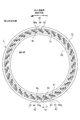
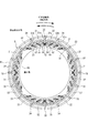
- FIG. 2 is a view showing a sliding surface of a sliding member of Example 1 as viewed from the arrow WW of FIG. 1.
- FIG. 8 is a diagram showing a sliding surface of a sliding member of Example 2 as viewed from the direction of arrows WW in FIG. 1.
- FIG. 8 is a diagram showing a sliding surface of a sliding member of Example 3 as seen from the arrow WW in FIG. 1. It is a partially expanded view of the sliding surface of FIG.
- FIG. 8 is a diagram showing a sliding surface of a sliding member of Example 4 as seen from the arrow WW of FIG. 1.
- FIG. 8 is a diagram showing a sliding surface of a sliding member of Example 5 as seen from the arrow WW of FIG. 1. It is a partially expanded view of the sliding surface of FIG. FIG. 8 is a diagram showing a sliding surface of a sliding member of Example 6 as viewed in the direction of arrows WW in FIG. 1.
- a sliding member according to a first embodiment of the present invention will be described with reference to FIGS. 1 and 2.
- a mechanical seal that is an example of a sliding member will be described.
- the outer peripheral side of the sliding member constituting the mechanical seal will be described as the sealed fluid side, and the inner peripheral side will be described as the leak side.
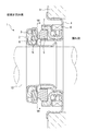
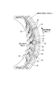
- FIG. 1 is a vertical cross-sectional view showing an example of the mechanical seal 1, which is an inside type that seals a sealed fluid that is about to leak from the outer circumference of the sliding surface toward the inner circumference. It consists of a side cartridge and a fixed side cartridge.
- the rotating side cartridge includes a sleeve 2 fitted on a rotating shaft 10, an annular rotating side sealing ring 3 as one sliding member, and a packing 8 for sealing between the sleeve 2 and the rotating side sealing ring 3.
- the rotation-side cartridge rotates integrally with the rotation shaft 10.
- the fixed-side cartridge includes a housing 4 attached to a casing 9, an annular fixed-side sealing ring 5 that is the other sliding member, a bellows 7 that seals the fixed-side sealing ring 5 and the housing, and a fixed-side sealing.
- the fixed side cartridge is fixed to the casing 9 in the rotational direction and the axial direction.
- FIG. 1 shows a case where the width of the sliding surface of the rotary side sealing ring 3 is wider than the width of the sliding surface of the fixed side sealing ring 5, the present invention is not limited to this, and in the opposite case. Needless to say, the present invention can also be applied to.
- the material of the rotating side sealing ring 3 and the stationary side sealing ring 5 is selected from silicon carbide (SiC) having excellent wear resistance and carbon having excellent self-lubricating property.
- the side seal ring 3 can be made of SiC and the fixed side seal ring 5 can be made of carbon.
- a negative pressure generating mechanism 41 and a branch portion 42 are provided on the leak side of the sliding surface S of the stationary seal ring 5.
- the negative pressure generating mechanism 41 is an annular bottomed groove. Further, the negative pressure generating mechanism 41 and the branch portion 42 are surrounded by the sealed fluid side land portion R1 and the leakage side land portion R2, and are isolated from the leakage side and the sealed fluid side.
- the branch portion 42 is a branch base portion 43 that radially branches from the negative pressure generating mechanism 41 toward the sealed fluid side, and a branch end that extends in the rotation direction (counterclockwise direction) of the mating sliding surface from the end portion of the branch base portion 43.
- the part 44 (the end part according to the present invention).
- the branch end portion 44 is a bottomed groove portion in which the radial width gradually tapers toward the downstream side, and is provided with a narrow step 44a surrounded by a land portion and having a stepwise narrowing depth. ing.
- the branch end portion 44 has an overlapping portion Lp that overlaps the adjacent branch portion 42 in the circumferential direction.
- the negative pressure generating mechanism 41 and the branch portion 42 are grooves having a depth of 0.1 ⁇ m to 10 ⁇ m.
- the negative pressure generating mechanism 41 and the branch portion 42 may have a constant depth or may be gradually shallower toward the narrowed step 44a of the branch end portion 44.
- the negative pressure generating mechanism 41 is integrally formed in an annular shape, but may be divided into a plurality of pieces with the land portion sandwiched in the circumferential direction.
- the fluid in the negative pressure generating mechanism 41 moves in the moving direction of the rotating seal ring 3 due to its viscosity. It follows and moves, and flows into the branch part 42 by the centrifugal force. At this time, the amount of fluid flowing out of the negative pressure generating mechanism 41 becomes larger than the amount of fluid flowing into the negative pressure generating mechanism 41, and the inside of the negative pressure generating mechanism 41 becomes negative pressure, causing cavitation.
- the sliding torque due to friction with gas of low viscosity becomes dominant, and the sliding torque can be reduced compared to conventional fluid lubrication with liquid. Further, since the negative pressure generating mechanism 41 has a negative pressure, a pumping action of sucking fluid from the leak side into the negative pressure generating mechanism 41 occurs, so that the leakage can be made extremely small.
- the inside of the negative pressure generating mechanism 41 is in a cavitation state, not all of it becomes a gas, and there is a flow of liquid.
- This liquid is heavier than gas and collects at the bottom of the negative pressure generating mechanism 41, and flows into the branch portion 42 due to the influence of centrifugal force.
- the fluid flowing into the branch portion 42 flows to the branch end portion 44 on the downstream side, and a large positive pressure is generated due to the throttling effect of the tapered groove portion of the branch end portion 44 and the wedge effect of the narrowing step 44a.
- the positive pressure spreads between the sliding surfaces S, and the sliding torque can be further reduced by bringing the sliding surfaces into a fluid lubrication state with a liquid film interposed.
- the branch end portion 44 of the branch portion 42 has an overlapping portion Lp that overlaps the adjacent branch portion 42 in the circumferential direction.
- the centrifugal force generated by the rotation of the rotary seal ring 3 and the overlapping portion Lp can prevent the high pressure generated at the branch end portion 44 of the branch portion 42 from leaking to the negative pressure generating mechanism 41.
- the high pressure generated at the branch portion can be efficiently used to reliably push and spread the sliding surface S to maintain the fluid lubrication state.
- the sliding member of Example 1 has the following effects. 1. Since cavitation is generated inside the negative pressure generating mechanism 41, friction due to a gas having a low viscosity becomes dominant in the negative pressure generating mechanism 41, and sliding torque can be reduced as compared with conventional fluid lubrication using liquid. . 2. Since the negative pressure generating mechanism 41 has a negative pressure, a pumping action of sucking the fluid into the negative pressure generating mechanism 41 from the leak side occurs, and the leakage can be extremely reduced. 3. The fluid flowing from the negative pressure generating mechanism 41 to the branch end portion 44 through the branch base portion 43 generates a large positive pressure due to the throttling effect of the tapered groove portion of the branch end portion 44 and the wedge effect of the narrowing step 44a.
- FIG. 3 shows the sliding surface S of the sliding member according to the second embodiment, which is different from the first embodiment in that the guide groove 45 is provided at the bottom of the negative pressure generating mechanism 41 and the branch portion 42.
- the same members and configurations as those of the first embodiment will be denoted by the same reference numerals, and overlapping description will be omitted.
- a negative pressure generating mechanism 41, a branch portion 42, and a guide groove 45 are arranged on the leak side of the sliding surface S of the stationary seal ring 5. Further, the negative pressure generating mechanism 41 and the branch portion 42 are surrounded by the sealed fluid side land portion R1 and the leak side land portion R2, and are separated from the leak side and the sealed fluid side.
- the configuration of the portion 42 is the same as that of the first embodiment.
- a guide groove 45 is provided at the bottom of the negative pressure generating mechanism 41, the branch portion 42, and the branch end portion 44.
- the guide grooves 45 are arranged at the bottoms of the negative pressure generating mechanism 41, the branch portion 42, and the branch end portion 44 with a predetermined number of streak-shaped grooves arranged at predetermined intervals, and as a whole, the negative pressure generating mechanism 41 separates the branch portion 42. It is arranged with a directivity toward the branch end 44.
- the fluid in the negative pressure generating mechanism 41 moves in the moving direction of the rotating seal ring 3 due to its viscosity. It follows and moves, and flows into the branch part 42. At this time, more fluid flows into the branch portion 42 than the fluid supplied into the negative pressure generating mechanism 41, and the inside of the negative pressure generating mechanism 41 becomes negative pressure, causing cavitation.
- the fluid that has passed from the negative pressure generating mechanism 41 through the branch portion 42 and concentrated at the branch end portion 44 on the downstream side of the branch portion 42 is large due to the throttling effect of the tapered groove portion of the branch end portion 44 and the wedge effect of the narrowing step 44a. Positive pressure is generated. The positive pressure spreads the sliding surfaces S, and the sliding torque can be reduced by bringing the sliding surfaces into a fluid lubrication state with a liquid film interposed.
- the guide groove 45 is arranged with a predetermined number of continuous streak-like grooves arranged at a predetermined interval so as to guide the flow from the negative pressure generating mechanism 41 to the branch portion and the branch end portion 44, but the present invention is not limited to this. Absent.
- the guide groove 45 may be independently arranged for each of the negative pressure generating mechanism 41, the branch base portion 43, and the branch end portion 44.
- the guide groove 45 is centrally arranged at a location where the flow is concentrated, and the negative pressure generating mechanism 41 moves to the branch base portion 43 and the branch end portion 44. You may make it guide a flow efficiently.
- the depth of the guide groove is deeper than the depth of the negative pressure generating mechanism 41, and is deeper by about 1 ⁇ m or more than the depth of the negative pressure generating mechanism 41 of 0.1 ⁇ m to 10 ⁇ m.
- the sliding member of the second embodiment exhibits the following effects in addition to the effects 1 to 5 of the first embodiment.
- the guide groove 45 arranged at the bottom of the negative pressure generating mechanism 41, the branch base portion 43, and the branch end portion 44 efficiently guides the fluid from the negative pressure generating mechanism 41 to the branch base portion 43 and the branch end portion 44.
- a large positive pressure is generated in the fluid guided to the branch end portion 44 due to the throttling effect of the tapered groove portion of the branch end portion 44 and the wedge effect of the narrowing step 44a.
- the positive pressure spreads the sliding surfaces S, and the sliding torque can be reduced by bringing the sliding surfaces into a fluid lubrication state with a liquid film interposed.
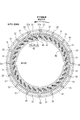
- FIG. 4 shows the sliding surface S of the sliding member according to the third embodiment, in which a fluid introducing groove 33, a dynamic pressure generating mechanism 31, and an opening groove 35 are provided in the land portion R1 on the sealed fluid side. Is different from the first embodiment.
- the configurations of the negative pressure generating mechanism 41 and the branch portion 42 are the same as those in the first embodiment.
- the same members and configurations as those of the first embodiment will be denoted by the same reference numerals, and overlapping description will be omitted.
- the sliding surface S of the fixed-side sealing ring 5 has a negative pressure generating mechanism 41, a branch portion 42, a guide groove 45, a fluid introduction groove 33 in the land portion R1 on the sealed fluid side, and a dynamic pressure.
- the generating mechanism 31 and the opening groove 35 are provided.
- an annular open groove 35 and a fluid introduction groove 33 having one end communicating with the sealed fluid side and the other end communicating with the open groove 35 are provided inside the land portion R1.
- the fluid introducing grooves 33 are provided at a predetermined number (16 in the embodiment of FIG. 4) at substantially equal intervals.
- a dynamic pressure generating mechanism 31 including a groove portion is arranged in the land portion R1.
- the dynamic pressure generating mechanism 31 has an opening 31a communicating with the fluid introduction groove 33 at one end (upstream end) and a toe 31b surrounded by a land R1 at the other end (downstream end). Have.
- the dynamic pressure generating mechanism 31 is a groove having a depth of 0.1 ⁇ m to 10 ⁇ m.
- the groove depths of the fluid introduction groove 33 and the opening groove 35 are formed to be about 10 to 50 times that of the dynamic pressure generating mechanism 31.
- the liquid in the cavitation is guided to the branch portion 42 by the negative pressure generating mechanism 41 and the guide groove 45 provided in the branch portion 42.
- a large positive pressure is generated in the liquid introduced to the branch portion 42 due to the throttling effect due to the tapered shape of the branch end portion 44 of the branch portion 42 and the wedge effect at the narrowing step 44a, so that the sliding surface S is expanded.
- the sliding surface S can be maintained in a fluid lubrication state.
- the fluid taken into the dynamic pressure generation mechanism 31 from the fluid introduction groove 33 generates a large positive pressure due to the wedge effect at the toe 31b.
- the sliding surface S is expanded and the fluid lubrication effect of the sliding surface S can be further enhanced.
- the fluid is supplied from the sealed fluid side at a plurality of locations on the sliding surface S. Therefore, when the fluid lubrication state is not sufficient in a low speed rotation state such as at start-up. Also, the sliding surface S can be lubricated by the fluid supplied from the fluid introduction groove 33.
- an open groove 35 is provided between the dynamic pressure generating mechanism 31, the negative pressure generating mechanism 41 and the branch portion 42.
- the open groove 35 has a function of releasing the dynamic pressure (positive pressure) generated by the dynamic pressure generating mechanism 31 to the same level as the pressure on the sealed fluid side, and a positive effect generated by the wedge effect in the narrowing step 44a of the branch end 44. Has a role of releasing pressure. This prevents the high-pressure fluid from the dynamic pressure generating mechanism 31 from flowing into the negative pressure generating mechanism 41, weakening the pumping effect of the negative pressure generating mechanism 41, and branching from the positive pressure generating function of the dynamic pressure generating mechanism 31. It is possible to prevent the positive pressure generating function of the portion 42 from interfering with each other (see FIG. 5).
- the sliding member of the third embodiment has the following effects in addition to the effects 1 to 4 of the first embodiment and the effects of the second embodiment.
- the fluid taken in from the fluid introducing groove 33 can generate a large positive pressure due to the wedge effect at the toe portion 31b.
- the sliding surface S is expanded and the fluid lubrication effect of the sliding surface S can be further enhanced.
- the fluid is supplied from the sealed fluid side at a plurality of locations on the sliding surface S, so that even when the fluid lubrication state is not sufficient in the low speed rotation state such as at the time of start-up.
- the fluid supplied from the fluid introduction groove 33 can contribute to the lubrication of the sliding surface S. 3.
- the opening groove 35 releases the dynamic pressure (positive pressure) generated by the dynamic pressure generating mechanism 31. This prevents the high-pressure fluid from flowing from the dynamic pressure generating mechanism 31 to the negative pressure generating mechanism 41 and weakening the pumping effect of the negative pressure generating mechanism 41, and at the same time, the positive pressure generating function and the branch portion of the dynamic pressure generating mechanism 31. It is possible to prevent the positive pressure generating function of 42 from interfering with each other.
- the branch portions 42 have the same shape, but the present invention is not limited to this, and the size, shape, or depth of the branch portions 42 may be different, or the branch portions 42 may be different. Some of them may be different in size, shape or depth.
- sliding member according to the fourth embodiment of the present invention will be described.
- the sliding members according to the first to third embodiments are suitable for unidirectional rotation
- the sliding member according to the fourth embodiment is a sliding member suitable for bidirectional rotation.
- the same members and configurations as those in the first to third embodiments are designated by the same reference numerals, and the duplicated description will be omitted.
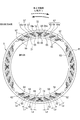
- a negative pressure generating mechanism 21 first branch parts 52, 62, 72 and second branch parts 74, 84 are provided on the leak side of the sliding surface S of the fixed side seal ring 5.
- the negative pressure generating mechanism 21 is an annular bottomed groove. Further, the negative pressure generating mechanism 21, the first branch parts 52, 62, 72 and the second branch parts 74, 84 are arranged in a predetermined number (four in the embodiment of FIG. 6) with the land part sandwiched therebetween. To be done.
- the negative pressure generating mechanism 21, the first branch portions 52, 62, 72 and the second branch portions 74, 84 are surrounded by the sealed fluid side land portion R1 and the leak side land portion R2, and are connected to the leak side and the sealed fluid side. It is isolated. Further, guide grooves 55, 65 are provided at the bottoms of the negative pressure generating mechanism 21, the first branch parts 52, 62, 72 and the second branch parts 74, 84.
- the first branch portion 52 includes a branch base portion 53 that radially branches from the negative pressure generating mechanism 21 toward the sealed fluid side, and a branch end portion 54 (the present invention that extends counterclockwise from the end portion of the branch base portion 53). End part).
- the first branch 62 includes a branch base 63 that radially branches from the negative pressure generating mechanism 21 toward the sealed fluid side, and a branch end 64 that extends clockwise from the end of the branch base 63. End portion according to the invention).
- the branch ends 54 and 64 are grooves that gradually taper in the radial direction, and are provided with narrowing steps 54a and 64a that are surrounded by lands and have a depth that decreases stepwise.
- the negative pressure generating mechanism 21 is provided with a predetermined number of first branch portions 52 and 62 (three in the embodiment of FIG. 6).
- a first branch part 72 is arranged to branch in the radial direction from the negative pressure generating mechanism 21 toward the sealed fluid side.
- the second branch part 74 is branched counterclockwise from the end of the first branch part 72, and the second branch part 84 is branched from the end of the first branch part 72 in the clockwise direction.
- the second branch portions 74 and 84 are narrowed bottomed groove portions whose width in the radial direction is gradually tapered, and the end portions thereof are surrounded by a land portion and the depth of the stepped portion 74a is narrowed stepwise. , 84a.
- the negative pressure generating mechanism 21, the first branch parts 52, 62, 72 and the second branch parts 74, 84 are grooves having a depth of 0.1 ⁇ m to 10 ⁇ m.
- the negative pressure generating mechanism 41 and the branch portion 42 may have a constant depth, or the branch end portions 54, 64 and the second branch portions 74, 84 may be narrowed and gradually shallowed toward the step. .
- the first branch portions 52 and 62 have overlapping portions Lp that overlap the adjacent first branch portions 52 and 62 in the circumferential direction.
- the second branch portions 74 and 84 each have an overlapping portion Lp that overlaps the adjacent first branch portions 52 and 62 in the circumferential direction.
- Guide grooves 55, 65 are provided at the bottoms of the negative pressure generating mechanism 21, the first branch parts 52, 62, 72 and the second branch parts 74, 84.
- a predetermined number of guide grooves 55, 65 are provided at the bottom of the negative pressure generating mechanism 21, the first branch portions 52, 62, 72 and the second branch portions 74, 84, and as a whole, the negative pressure generating mechanism 21 and the branch end portion 54.
- 64, and the second branch parts 74, 84 are directed toward the tips.
- a normal liquid flow also exists inside the negative pressure generating mechanism 21 in the cavitation state. Since this liquid is heavier than gas and collects at the bottom of the negative pressure generating mechanism 21, the guide grooves 55 provided at the bottoms of the negative pressure generating mechanism 21, the first branch parts 52, 62, 72 and the second branch parts 74, 84, By 65, the liquid can be efficiently guided from the negative pressure generating mechanism 21 to the first branch parts 52, 62, 72 and the second branch parts 74, 84.
- the liquid introduced from the negative pressure generating mechanism 21 to the first branch parts 52, 62, 72 and the second branch parts 74, 84 is a throttling effect due to the tapered shape of the branch end parts 54, 64 and the second branch parts 74, 84.
- first branch portions 52 and 62 are overlapped portions Lp that overlap the adjacent first branch portions 52 and 62 in the circumferential direction
- second branch portions 74 and 84 are the adjacent first branch portions 52 and 62, respectively.
- first branch portion 52 having the branch end portion 54 extending in the counterclockwise direction and the first branch portion 62 having the branch end portion 64 extending in the clockwise direction are arranged in the circumferential direction of the negative pressure generating mechanism 21. Are arranged symmetrically with respect to the radial axis connecting the center of the and the center of rotation.
- second branch portion 74 extending in the counterclockwise direction and the second branch portion 84 extending in the clockwise direction are also arranged with respect to the radial axis connecting the center of the negative pressure generating mechanism 21 in the circumferential direction and the rotation center. And are arranged symmetrically.
- the negative pressure generating mechanism 21 sucks the fluid from the leak side into the negative pressure generating mechanism 21 by the negative pressure not only when the rotary seal ring 3 rotates counterclockwise but also when it rotates clockwise.
- the pumping action is exerted, and the first branch portion 52 and the first branch portion 62, and the second branch portion 74 and the second branch portion 84 can generate a high pressure to exert a fluid lubrication effect.
- the sliding member of Example 4 has the following effects. 1. By generating a negative pressure in the negative pressure generating mechanism 21 so that the inside of the negative pressure generating mechanism 21 serves as a cavitation region, the friction due to the gas becomes dominant in the negative pressure generating mechanism 21, so that the fluid generated by the conventional liquid is used. Sliding torque can be reduced compared to lubrication. 2. Since the negative pressure generating mechanism 21 has a negative pressure, the pumping action of sucking the fluid into the negative pressure generating mechanism 21 from the leak side is exhibited, so that the leakage can be reduced. 3.
- the negative pressure generating mechanism 21, the first branch portions 52, 62, 72 and the guide grooves 55, 65 provided at the bottoms of the second branch portions 74, 84 allow the negative pressure generating mechanism 21 to move to the first branch portions 52, 62.
- the liquid can be efficiently guided to the 72 and the second branch portions 74 and 84. 4.
- the liquid introduced from the negative pressure generating mechanism 21 to the first branch parts 52, 62, 72 and the second branch parts 74, 84 has a squeezing effect due to the tapered shapes of the branch end parts 54, 64 and the second branch parts 74, 84. Then, a large positive pressure is generated due to the wedge effect of the narrowed steps 54a, 64a, 74a, 84a.
- the sliding surface S is spread by this positive pressure, and the sliding surface S can be maintained in a fluid lubricated state.
- the first branch portions 52, 62 and the second branch portions 74, 84 have overlapping portions Lp that overlap the adjacent first branch portions 52, 62 in the circumferential direction. Due to the overlapping portion Lp, the branch ends 54 and 64 and the second branch portions 74 and 84 that generate high pressure do not directly face the negative pressure generating mechanism 21, so that the fluid having high pressure generates negative pressure. It is possible to prevent it from directly flowing into the mechanism 21. As a result, the high positive pressure generated at the branch portion can be efficiently used to reliably maintain the fluid lubrication state of the sliding surface S. 6.
- a guide groove is provided at the bottom of the negative pressure generating mechanism 21, the first branch parts 52, 62, 72 and the second branch parts 74, 84, but the same as in the first embodiment.
- the guide groove may not be provided.
- FIG. 7 shows the sliding surface S of the sliding member according to the fifth embodiment.
- the fluid introducing grooves 33, 34, the dynamic pressure generating mechanisms 31, 32 and the opening groove 35 are provided in the land R1 on the sealed fluid side.
- the configurations of the negative pressure generating mechanism 21, the first branch parts 52, 62, 72, the second branch parts 74, 84, and the guide grooves 55, 65 are the same as those in the fourth embodiment.
- the same members and configurations as those in the fourth embodiment will be designated by the same reference numerals, and overlapping description will be omitted.
- the sliding surface S of the fixed-side sealing ring 5 has a negative pressure generating mechanism 21, a first branch portion 52, 62, 72, and a second branch portion 74, 84 in the land R2 on the leak side.
- the guide grooves 55 and 65, and the fluid introduction grooves 33 and 34, the dynamic pressure generating mechanisms 31 and 32, and the opening groove 35 are provided in the land portion R1 on the sealed fluid side.
- the negative pressure generating mechanism 21, the first branch parts 52, 62, 72, the second branch parts 74, 84, and the guide grooves 55, 65 are surrounded by the land part R2 on the leak side, and are isolated from the sealed fluid side and the leak side. ing.
- the negative pressure generating mechanism 21, the first branch parts 52, 62, 72, the second branch parts 74, 84, and the guide grooves 55, 65 have the same configurations as those of the fourth embodiment, and therefore the description thereof will be omitted.
- an annular open groove 35 and fluid introduction grooves 33, 34 having one end communicating with the sealed fluid side and the other end communicating with the open groove 35 are provided.
- the fluid introduction grooves 33 and 34 are provided in a predetermined number (8 in the embodiment of FIG. 7) alternately at approximately equal intervals.
- dynamic pressure generating mechanisms 31 and 32 are provided in the land portion R1, one end of each of the dynamic pressure generating mechanisms 31 and 32 communicates with the fluid introduction groove 33 through the openings 31a and 32a, and the other end thereof is the land portion R1. It is composed of a groove portion having toe portions 31b and 32b surrounded by.
- the fluid introduction groove 33 communicates with the sealed fluid side and the open groove 35, and also with the dynamic pressure generating mechanisms 31, 32.
- the fluid introducing groove 34 only communicates with the sealed fluid side and the open groove 35, and does not communicate with the dynamic pressure generating mechanisms 31, 32.
- the dynamic pressure generating mechanisms 31 and 32 are grooves each having a depth of 0.1 ⁇ m to 10 ⁇ m.
- the depths of the fluid introduction grooves 33, 34 and the open groove 35 are formed to be about 10 to 50 times as deep as the dynamic pressure generating mechanisms 31, 32.
- the sliding member (rotary seal ring 3) on the mating side rotates counterclockwise, the fluid introduced from the fluid introduction groove 33 into the dynamic pressure generating mechanism 31 produces a large positive pressure due to the wedge effect at the toe 31b. .
- the sliding surface S is expanded and the fluid lubrication effect of the sliding surface S can be further enhanced.
- the fluid is supplied from the sealed fluid side at a plurality of locations on the sliding surface S, so that the fluid lubrication state is not sufficient in a low speed rotation state such as at the time of startup. Even if there is, the fluid supplied from the fluid introduction grooves 33, 34 can contribute to the lubrication of the sliding surface S.
- the rotary side sealing ring 3 is a clock.
- the sliding surface S is expanded regardless of whether it is rotated in the clockwise direction or the counterclockwise direction, and the sliding torque can be reduced by bringing the sliding surface S into a fluid lubrication state with a liquid film interposed.
- an open groove 35 is provided between the dynamic pressure generating mechanisms 31, 32 and the negative pressure generating mechanism 21, the first branch parts 52, 62, 72, and the second branch parts 74, 84.
- the opening groove 35 has a function of releasing the dynamic pressure (positive pressure) generated by the dynamic pressure generating mechanisms 31, 32 to the same level as the pressure on the sealed fluid side, the first branch parts 52, 62, 72, and the second branch part. It has a role of guiding a large positive pressure generated by the wedge effect in the branch portions 74 and 84 to the open groove 35 and releasing it to the high pressure fluid side.
- the sliding member of the fifth embodiment exhibits the following effects in addition to the effects 1 to 6 of the fourth embodiment.
- a plurality of fluid introduction grooves 33, 34 are provided, the fluid is supplied from the sealed fluid side at a plurality of locations on the sliding surface S.
- the fluid supplied from the fluid introduction grooves 33, 34 can contribute to the lubrication of the sliding surface S.
- the fluid introduced from the fluid introduction groove 33 generates a large positive pressure due to the wedge effect in the toe 31b, so that the sliding surface S is spread and the liquid film is formed on the sliding surface S.
- the sliding torque can be reduced by establishing a fluid lubrication state with the interposition of. 3.
- the dynamic pressure generating mechanisms 31, 32 are formed symmetrically with respect to the fluid introduction groove 33, it is possible to reliably generate a large positive pressure regardless of whether the rotation side sealing ring 3 rotates in the forward or reverse direction. 4.
- the open groove 35 releases the positive pressure generated by the dynamic pressure generating mechanisms 31, 32 and the large positive pressure generated by the first branch portions 52, 62, 72 and the second branch portions 74, 84 to the high pressure fluid side. Therefore, it is possible to prevent the high-pressure fluid from the dynamic pressure generating mechanisms 31 and 32 from flowing into the negative pressure generating mechanism 21 to weaken the pumping effect of the negative pressure generating mechanism 21, and to increase the positive pressure of the dynamic pressure generating mechanisms 31 and 32. It is possible to prevent the generating function from interfering with the positive pressure generating function of the first branch portions 52, 62, 72 and the second branch portions 74, 84.
- the dynamic pressure generating mechanism 31 extending in the counterclockwise direction and the dynamic pressure generating mechanism 32 extending in the clockwise direction are symmetrically arranged with respect to the fluid introduction groove 33, but the invention is not limited to this. .
- the dynamic pressure generating mechanism 31 and the dynamic pressure generating mechanism 32 may have different shapes, sizes, and depths. Further, the dynamic pressure generating mechanism 31 and the dynamic pressure generating mechanism 32 may be displaced in the radial direction with respect to the fluid introduction groove 33.
- FIG. 9 shows the sliding surface S of the sliding member according to the sixth embodiment.
- the same number of the first branch portions 52 extending in the counterclockwise direction and the first branch portions 62 extending in the clockwise direction are arranged.
- the sixth embodiment is different in that the numbers of the first branch portions 52 and the first branch portions 62 are different.
- the configurations of the negative pressure generating mechanism 21, the first branch parts 52, 62, 72, the second branch parts 74, 84, and the guide grooves 55, 65 are the same as those in the fourth embodiment.
- the same members and configurations as those in the fourth embodiment will be designated by the same reference numerals, and overlapping description will be omitted.
- a negative pressure generating mechanism 21, first branch parts 52, 62, 72 and second branch parts 74, 84 are provided on the leak side of the sliding surface S of the fixed side seal ring 5.
- the negative pressure generating mechanism 21 is an annular bottomed groove. Further, the negative pressure generating mechanism 21, the first branch parts 52, 62, 72 and the second branch parts 74, 84 slide a predetermined number (four in the embodiment of FIG. 9) across the land part. It is arranged on the surface S.
- the negative pressure generating mechanism 21, the first branch portions 52, 62, 72 and the second branch portions 74, 84 are surrounded by the sealed fluid side land portion R1 and the leak side land portion R2, and are connected to the leak side and the sealed fluid side. It is isolated. Further, guide grooves 55, 65 are provided at the bottoms of the negative pressure generating mechanism 21, the first branch parts 52, 62, 72 and the second branch parts 74, 84.
- the first branch portion 52 includes a branch base portion 53 that radially branches from the negative pressure generating mechanism 21 toward the sealed fluid side, and a branch end portion 54 (the present invention that extends counterclockwise from the end portion of the branch base portion 53). End part).
- the first branch 62 includes a branch base 63 that radially branches from the negative pressure generating mechanism 21 toward the sealed fluid side, and a branch end 64 that extends clockwise from the end of the branch base 63. End portion according to the invention).
- a predetermined number of first branch portions 52 (five in the embodiment of FIG. 9) and a predetermined number of first branch portions 62 (one in the embodiment of FIG. 9) are arranged in one negative pressure generating mechanism 21. There is.
- first branch portion 72 that branches in the radial direction from the negative pressure generating mechanism 21 toward the sealed fluid side is disposed between the first branch portion 52 and the first branch portion 62.
- One second branch 74 is provided to branch from the end of the first branch 72 in the counterclockwise direction, and one second branch 84 is provided to branch from the end of the first branch 72 in the clockwise direction.
- the number of first branch portions 52 extending counterclockwise is larger than the number of first branch portions 62 extending clockwise. This makes it possible to provide a sliding member that is suitable for a device that is frequently used counterclockwise and is rarely used clockwise.
- the ratio between the number of the first branch portions 52 extending in the counterclockwise direction and the number of the first branch portions 62 extending in the clockwise direction can be determined according to specific usage conditions.
- the size, shape, and depth of the first branch portion 52 extending in the counterclockwise direction and the size of the first branch portion 62 extending in the clockwise direction may be different depending on the frequency of use in the rotation direction.
- the shapes, sizes, and depths of the first branch portions 52 or the first branch portions 62 may be different from each other.
- the number, size, shape, and depth of the second branch portion 74 extending in the counterclockwise direction and the second branch portion 84 extending in the clockwise direction also differ according to the frequency of use in the rotation direction. You may do it.
- the strength of the fluid lubrication function can be changed depending on the direction of rotation. For example, when the number of the first branch portion 52 and the second branch portion 74 extending in the counterclockwise direction is larger than that of the first branch portion 62 and the second branch portion 84 extending in the clockwise direction, the clockwise rotation is performed. The fluid lubrication function during counterclockwise rotation can be enhanced more than that.
- a guide groove is provided at the bottom of the negative pressure generating mechanism 21, the first branch parts 52, 62, 72 and the second branch parts 74, 84, but the same as in the first embodiment.
- the guide groove may not be provided.
- the outer peripheral side is the sealed fluid side and the inner peripheral side is the leak side.
- the present invention is not limited to this, and it is also applicable when the inner peripheral side is the sealed fluid side and the outer peripheral side is the leak side.
- the negative pressure generating mechanism, the land portion and the guide groove are provided on the sliding surface S of the fixed side sealing ring 5, they may be provided on the sliding surface of the rotating side sealing ring 3.
Abstract
Description
摺動面にて互いに相対摺動する一対の摺動部材であって,
少なくとも一方の前記摺動面は,ランド部に囲まれた負圧発生機構と,
前記摺動面内に配設されるとともに前記負圧発生機構から分岐する第1分岐部と,を備えることを特徴としている。
この特徴によれば,負圧発生機構内は圧力低下によりキャビテーションが発生して,流体が気化するので,粘性の小さい気体との摺動が支配的となり,摺動トルクを低減することができる。また,負圧発生機構内の負圧によって漏れ側から摺動面内に流体を吸い込むポンピング作用が得られるので,漏れを極めて小さくできる。さらに,第1分岐部におけるくさび効果によって正圧を発生して摺動面を流体潤滑状態に保つことができる。従来技術のように正圧発生機構と負圧発生機構を別個に設けることなく,一つの負圧発生機構によって,摺動トルクの低減及び密封性の向上という相反する性能を向上することができるので小形化が可能となる。 In order to solve the above problems, the sliding member of the present invention comprises:
A pair of sliding members that slide relative to each other on a sliding surface,
At least one of the sliding surfaces has a negative pressure generating mechanism surrounded by lands,
A first branch portion disposed in the sliding surface and branched from the negative pressure generating mechanism.
According to this feature, cavitation is generated in the negative pressure generating mechanism due to the pressure drop, and the fluid is vaporized, so that sliding with a gas having low viscosity becomes dominant and the sliding torque can be reduced. Further, the negative pressure in the negative pressure generating mechanism provides a pumping action of sucking fluid into the sliding surface from the leak side, so that the leak can be made extremely small. Further, the wedge effect in the first branch portion can generate a positive pressure to keep the sliding surface in a fluid lubricated state. Since the negative pressure generating mechanism can improve the contradictory performance of reducing sliding torque and improving sealing performance without separately providing a positive pressure generating mechanism and a negative pressure generating mechanism as in the prior art. Miniaturization is possible.
前記摺動面内に配設されるとともに前記第1分岐部から分岐する第2分岐部をさらに備えることを特徴としている。
この特徴によれば,第1分岐部がさらに第2分岐部によって分岐するので,両回転機器に容易に適用できる。 The sliding member of the present invention is
It is characterized in that it further comprises a second branch portion disposed in the sliding surface and branched from the first branch portion.
According to this feature, the first branching portion is further branched by the second branching portion, so that it can be easily applied to both rotating devices.
前記第1分岐部は,隣接する前記第1分岐部と周方向に重なる重なり部を備えることを特徴としている。
この特徴によれば,第1分岐部は,隣接する第1分岐部と周方向に重なる重なり部を有するので,高い正圧を発する第1分岐部から負圧発生機構への漏れ流れを規制して,第1分岐部が発生する高い正圧の利用効率を高め,摺動面を流体潤滑状態に維持することができる。 The sliding member of the present invention is
The first branch portion is provided with an overlapping portion that overlaps the adjacent first branch portion in the circumferential direction.
According to this feature, since the first branch portion has the overlapping portion that overlaps with the adjacent first branch portion in the circumferential direction, the leakage flow from the first branch portion that generates a high positive pressure to the negative pressure generating mechanism is restricted. As a result, the utilization efficiency of the high positive pressure generated by the first branch portion can be improved, and the sliding surface can be maintained in a fluid lubricated state.
前記第2分岐部は,隣接する前記第1分岐部と周方向に重なる重なり部を備えることを特徴としている。
この特徴によれば,第2分岐部は,隣接する第1分岐部と周方向に重なる重なり部を有するので,高い正圧を発する第2分岐部から負圧発生機構への漏れ流れを規制して,第2分岐部が発生する高い正圧の利用効率を高め,摺動面を流体潤滑状態に維持することができる。 The sliding member of the present invention is
The second branch portion is characterized by including an overlapping portion that overlaps the adjacent first branch portion in the circumferential direction.
According to this feature, since the second branch portion has the overlapping portion that overlaps the adjacent first branch portion in the circumferential direction, the leakage flow from the second branch portion that generates a high positive pressure to the negative pressure generating mechanism is restricted. As a result, the utilization efficiency of the high positive pressure generated by the second branch portion can be improved, and the sliding surface can be maintained in a fluid lubricated state.
少なくとも前記負圧発生機構は,前記負圧発生機構から前記第1分岐部へ向かうガイドグルーブを備えることを特徴としている。
この特徴によれば,少なくとも負圧発生機構の底部を流れる流体をガイドグルーブにより所望の方向へ導くことができる。 The sliding member of the present invention is
At least the negative pressure generating mechanism includes a guide groove extending from the negative pressure generating mechanism toward the first branch portion.
According to this feature, at least the fluid flowing at the bottom of the negative pressure generating mechanism can be guided in the desired direction by the guide groove.
時計方向に延設される前記第1分岐部及び反時計方向に延設される前記第1分岐部を備えることを特徴としている。
この特徴によれば,時計方向に延設される第1分岐部及び反時計方向に延設される第1分岐部を備えるので,両回転機器に容易に適用できる。 The sliding member of the present invention is
It is characterized by including the first branch portion extending in the clockwise direction and the first branch portion extending in the counterclockwise direction.
According to this feature, since the first branch portion extending in the clockwise direction and the first branch portion extending in the counterclockwise direction are provided, it can be easily applied to both rotating devices.
前記第1分岐部の端部は先細りの溝部であることを特徴としている。
この特徴によれば,第1分岐部を流れる液体は,端部の先細りの溝部により絞られて圧力が上昇するので,摺動面に液膜を介在させた流体潤滑状態とすることにより摺動トルクを低減できる。 The sliding member of the present invention is
The end portion of the first branch portion is a tapered groove portion.
According to this feature, the liquid flowing through the first branch portion is squeezed by the tapered groove portion at the end portion and the pressure increases, so that the sliding surface is slid by the fluid lubrication state with the liquid film interposed. Torque can be reduced.
時計方向に延設される前記第2分岐部及び反時計方向に延設される前記第2分岐部を備えることを特徴としている。
この特徴によれば,時計方向に延設される第2分岐部及び反時計方向に延設される第2分岐部を備えるので,両回転機器に容易に適用できる。 The sliding member of the present invention is
It is characterized by including the second branch portion extending in the clockwise direction and the second branch portion extending in the counterclockwise direction.
According to this feature, since the second branch portion extending in the clockwise direction and the second branch portion extending in the counterclockwise direction are provided, it can be easily applied to both rotating devices.
前記第2分岐部は先細りの溝部であることを特徴としている。
この特徴によれば,第2分岐部を流れる液体は,先細りの溝部により絞られて圧力が上昇するので,摺動面に液膜を介在させた流体潤滑状態とすることにより摺動トルクを低減できる。 The sliding member of the present invention is
The second branch portion is characterized in that it is a tapered groove portion.
According to this feature, since the liquid flowing through the second branch portion is narrowed by the tapered groove portion and the pressure rises, the sliding torque is reduced by bringing the liquid surface into the fluid lubrication state. it can.
前記負圧発生機構の周方向の中心と回転中心とを結ぶ径方向軸に対して,前記第1分岐部及び前記第2分岐部は対称に配設されることを特徴としている。
この特徴によれば,分岐部は,径方向軸に対して対称に配設されているので,正回転,逆回転に関わらず流体潤滑効果及びポンピング効果を発揮することができる。 The sliding member of the present invention is
The first branch portion and the second branch portion are arranged symmetrically with respect to a radial axis connecting the center of the negative pressure generating mechanism in the circumferential direction and the center of rotation.
According to this feature, since the branch portions are symmetrically arranged with respect to the radial axis, the fluid lubrication effect and the pumping effect can be exhibited regardless of the forward rotation and the reverse rotation.
前記負圧発生機構は,前記摺動面に複数配設されることを特徴としている。
この特徴によれば,摺動面の大きさに応じて,負圧発生機構及び分岐部を最適に配置することができる。 The sliding member of the present invention is
A plurality of the negative pressure generating mechanisms are arranged on the sliding surface.
According to this feature, the negative pressure generating mechanism and the branch portion can be optimally arranged according to the size of the sliding surface.
被密封流体側に連通する流体導入溝と,一端が前記流体導入溝に連通するとともに他端がランド部によって囲まれる動圧発生機構と,ランド部内に設けられるとともに前記流体導入溝に連通する開放溝と,をさらに備えることを特徴としている。
この特徴によれば,摺動面は,流体導入溝から流体が供給されるので,起動時などの低速回転状態において流体潤滑状態が十分でないときであっても,流体導入溝から供給される流体によって,摺動面Sの潤滑することができるとともに,動圧発生機構が流体導入溝から取り入れた流体をくさび効果により大きな正圧を発生して,摺動面を流体潤滑状態に保つことができる。 The sliding member of the present invention is
A fluid introduction groove communicating with the sealed fluid side, a dynamic pressure generating mechanism having one end communicating with the fluid introduction groove and the other end surrounded by a land portion, and an opening provided in the land portion and communicating with the fluid introduction groove A groove is further provided.
According to this feature, since the fluid is supplied from the fluid introduction groove to the sliding surface, the fluid supplied from the fluid introduction groove can be supplied even when the fluid lubrication state is not sufficient in the low speed rotation state such as at the start-up. As a result, the sliding surface S can be lubricated, and the dynamic pressure generating mechanism can generate a large positive pressure by the wedge effect of the fluid taken in from the fluid introduction groove to keep the sliding surface in a fluid lubricated state. .
時計方向に延設される前記動圧発生機構及び反時計方向に延設される前記動圧発生機構を備えることを特徴とするとしている。
この特徴によれば,時計方向に延設される動圧発生機構及び反時計方向に延設される動圧発生機構によって,回転方向に関係なく確実に大きな正圧を発生して,摺動面を流体潤滑状態に保つことができる。 The sliding member of the present invention is
The present invention is characterized by including the dynamic pressure generating mechanism extending in the clockwise direction and the dynamic pressure generating mechanism extending in the counterclockwise direction.
According to this feature, the dynamic pressure generating mechanism extending in the clockwise direction and the dynamic pressure generating mechanism extending in the counterclockwise direction reliably generate a large positive pressure irrespective of the rotation direction, and the sliding surface Can be kept in a fluid lubrication state.
前記動圧発生機構は前記流体導入溝に対し対称に配置されること特徴としている。
この特徴によれば,動圧発生機構は流体導入溝に対し対称に配置されているので,正回転,逆回転に関わらず流体潤滑効果及びポンピング効果を発揮することができる。 The sliding member of the present invention is
The dynamic pressure generating mechanism is arranged symmetrically with respect to the fluid introduction groove.
According to this feature, since the dynamic pressure generation mechanism is symmetrically arranged with respect to the fluid introduction groove, the fluid lubrication effect and the pumping effect can be exhibited regardless of the forward rotation and the reverse rotation.
1.負圧発生機構41はその内部にキャビテーションが発生するので,負圧発生機構41内では粘性の小さい気体による摩擦が支配的となり,従来の液体による流体潤滑に比べ摺動トルクを低減することができる。
2.負圧発生機構41内は負圧となるので,漏れ側から負圧発生機構41内に流体を吸い込むポンピング作用が生じ,漏れを極めて小さくできる。
3.負圧発生機構41から分岐基部43を通り分岐端部44に流れ込んだ流体は,分岐端部44の先細り溝部による絞り効果と,狭まり段差44aによるくさび効果により大きな正圧が発生する。この正圧により摺動面S間は押し広げられ,摺動面に液膜を介在させた流体潤滑状態とすることにより摺動トルクを一層低減することができる。
4.分岐部42の分岐端部44は隣接する分岐基部43と周方向に重なる重なり部Lpを有するので,高い圧力を発生する分岐端部44から負圧発生機構41への漏れ流れを規制できる。これにより,分岐部42が発生する高い圧力を効率良く利用して,確実に摺動面Sの流体潤滑状態を維持することができる。
5.従来技術のように正圧発生機構と負圧発生機構を別個に設けることなく,摺動トルクの低減及び密封性の向上という相反する性能を向上することができるので小形化が可能となる。 As described above, the sliding member of Example 1 has the following effects.
1. Since cavitation is generated inside the negative
2. Since the negative
3. The fluid flowing from the negative
4. Since the
5. Since it is possible to improve the contradictory performances of reducing the sliding torque and improving the sealing performance without separately providing the positive pressure generating mechanism and the negative pressure generating mechanism as in the prior art, it is possible to reduce the size.
負圧発生機構41,分岐基部43及び分岐端部44の底部に配設されたガイドグルーブ45によって,流体は,負圧発生機構41から分岐基部43及び分岐端部44へ効率的に導かれる。分岐端部44に導かれた流体は,分岐端部44の先細りの溝部による絞り効果と,狭まり段差44aによるくさび効果により大きな正圧が発生する。この正圧により摺動面S間は押し広げられ,摺動面に液膜を介在させた流体潤滑状態とすることにより摺動トルクを低減することができる。 As described above, the sliding member of the second embodiment exhibits the following effects in addition to the
The
1.動圧発生機構31は,流体導入溝33から取り入れた流体が止端部31bにおけるくさび効果により大きな正圧を発生させることができる。これにより,摺動面Sは押し広げられ,摺動面Sの流体潤滑効果を一層高めることができる。
2.流体導入溝33が複数設けられることにより,摺動面Sは複数箇所で被密封流体側から流体が供給されるので,起動時などの低速回転状態において流体潤滑状態が十分でないときであっても,流体導入溝33から供給される流体によって,摺動面Sの潤滑に寄与することができる。
3.開放溝35は,動圧発生機構31で発生した動圧(正圧)を開放する。これにより,動圧発生機構31から負圧発生機構41へ高圧流体が流れ込んで,負圧発生機構41のポンピング効果が弱まることを防止するとともに,動圧発生機構31の正圧発生機能と分岐部42の正圧発生機能が干渉するのを防止することができる。 As described above, the sliding member of the third embodiment has the following effects in addition to the
1. In the dynamic
2. By providing the plurality of
3. The opening
1.負圧発生機構21に負圧を発生させて,負圧発生機構21の内部をキャビテーション領域とすることによって,負圧発生機構21においては気体による摩擦が支配的となるので,従来の液体による流体潤滑に比べ摺動トルクを低減することができる。
2.負圧発生機構21内は負圧となるので,漏れ側から負圧発生機構21内に流体を吸い込むポンピング作用を発揮するので,漏れを低減できる。
3.負圧発生機構21,第1分岐部52,62,72及び第2分岐部74,84の底部に設けられたガイドグルーブ55,65により,負圧発生機構21から第1分岐部52,62,72及び第2分岐部74,84へ液体を効率良く導くことができる。
4.負圧発生機構21から第1分岐部52,62,72及び第2分岐部74,84へ導かれた液体は,分岐端部54,64,第2分岐部74,84の先細り形状による絞り効果と,狭まり段差54a,64a,74a,84aによるくさび効果により大きな正圧が発生する。この正圧により摺動面Sは押し広げられ,摺動面Sを流体潤滑状態に維持することができる。
5.第1分岐部52,62,第2分岐部74,84は,それぞれ隣接する第1分岐部52,62と周方向に重なる重なり部Lpを有する。重なり部Lpによって,高い圧力を発生する分岐端部54,64及び第2分岐部74,84は,負圧発生機構21と直接に面することがなくなるので,高い圧力を有する流体が負圧発生機構21へ直接流れ込むことを防ぐことができる。これにより,分岐部が発生する高い正圧を効率良く利用して,確実に摺動面Sの流体潤滑状態を維持することができる。
6.第1分岐部52及び第1分岐部62,並びに,第2分岐部74と第2分岐部84は,負圧発生機構21の周方向の中心と回転中心とを結ぶ径方向軸に対して,対称に配設されている。これにより,回転方向に関係なく,上記1~5の効果を発揮することができる。
7.従来技術のように正圧発生機構と負圧発生機構を別個に設けることなく,一つの負圧発生機構によって,摺動トルクの低減及び密封性の向上という相反する性能を向上することができるので小形化が可能となる。 As described above, the sliding member of Example 4 has the following effects.
1. By generating a negative pressure in the negative
2. Since the negative
3. The negative
4. The liquid introduced from the negative
5. The
6. The
7. Since it is possible to improve the contradictory performance of reducing sliding torque and improving sealing performance by one negative pressure generating mechanism without separately providing a positive pressure generating mechanism and a negative pressure generating mechanism as in the prior art. Miniaturization is possible.
1.流体導入溝33,34が複数設けられることにより,摺動面Sは複数箇所で被密封流体側から流体が供給されるので,起動時などの低速回転状態において流体潤滑状態が十分でないときであっても,流体導入溝33,34から供給される流体によって,摺動面Sの潤滑に寄与することができる。
2.動圧発生機構31,32は,流体導入溝33から取り入れた流体が止端部31bにおけるくさび効果により大きな正圧を発生させるので,摺動面Sが押し広げられ,摺動面Sに液膜を介在させた流体潤滑状態とすることにより摺動トルクを低減することができる。
3.動圧発生機構31,32は,流体導入溝33に対して対称に形成されるので,回転側密封環3が正逆どちらに回転しても確実に大きな正圧を発生させることができる。
4.開放溝35は,動圧発生機構31,32にて発生した正圧及び第1分岐部52,62,72,及び第2分岐部74,84にて発生した大きな正圧を高圧流体側に逃すので,動圧発生機構31,32からの高圧の流体が負圧発生機構21へ流れ込んで,負圧発生機構21のポンピング効果が弱まることを防止するとともに,動圧発生機構31,32の正圧発生機能と第1分岐部52,62,72,及び第2分岐部74,84との正圧発生機能が干渉するのを防止することができる。 As described above, the sliding member of the fifth embodiment exhibits the following effects in addition to the
1. Since a plurality of
2. In the dynamic
3. Since the dynamic
4. The
2 スリーブ
3 回転側密封環
4 ハウジング
5 固定側密封環
6 コイルドウェーブスプリング
7 ベローズ
8 パッキン
9 ケーシング
10 回転軸
21 負圧発生機構
31 動圧発生機構
31a 開口部
31b 止端部
32 動圧発生機構
32a 開口部
32b 止端部
33 流体導入溝
34 流体導入溝
35 開放溝
37 第2分岐部
41 負圧発生機構
42 分岐部(第1分岐部)
43 分岐基部
44 分岐端部(端部)
44a 狭まり段差
45 ガイドグルーブ
52 第1分岐部
53 分岐基部
54 分岐端部(端部)
54a 狭まり段差
55 ガイドグルーブ
62 第1分岐部
63 分岐基部
64 分岐端部(端部)
65 ガイドグルーブ
64a 狭まり段差
72 第1分岐部
74 第2分岐部
74a 狭まり段差
84 第2分岐部
84a 狭まり段差
Lp 重なり部
R1 被密封流体側ランド部
R2 漏れ側ランド部
S 摺動面 1
43
65
Claims (14)
- 摺動面にて互いに相対摺動する一対の摺動部材であって,
少なくとも一方の前記摺動面は,ランド部に囲まれた負圧発生機構と,
前記摺動面内に配設されるとともに前記負圧発生機構から分岐する第1分岐部と,を備えることを特徴とする摺動部材。 A pair of sliding members that slide relative to each other on a sliding surface,
At least one of the sliding surfaces has a negative pressure generating mechanism surrounded by lands,
And a first branch portion disposed in the sliding surface and branched from the negative pressure generating mechanism. - 前記摺動面内に配設されるとともに前記第1分岐部から分岐する第2分岐部をさらに備えることを特徴とする請求項1に記載の摺動部材。 The sliding member according to claim 1, further comprising a second branch portion that is disposed in the sliding surface and branches from the first branch portion.
- 前記第1分岐部は,隣接する前記第1分岐部と周方向に重なる重なり部を備えることを特徴とする請求項2に記載の摺動部材。 The sliding member according to claim 2, wherein the first branch portion includes an overlapping portion that circumferentially overlaps the adjacent first branch portion.
- 前記第2分岐部は,隣接する前記第1分岐部と周方向に重なる重なり部を備えることを特徴とする請求項2又は3に記載の摺動部材。 The sliding member according to claim 2 or 3, wherein the second branch portion includes an overlapping portion that circumferentially overlaps the adjacent first branch portion.
- 少なくとも前記負圧発生機構は,前記負圧発生機構から前記第1分岐部へ向かうガイドグルーブを備えることを特徴とする請求項2ないし4のいずれかに記載の摺動部材。 5. The sliding member according to claim 2, wherein at least the negative pressure generating mechanism includes a guide groove extending from the negative pressure generating mechanism toward the first branch portion.
- 時計方向に延設される前記第1分岐部及び反時計方向に延設される前記第1分岐部を備えることを特徴とする請求項2ないし5のいずれかに記載の摺動部材。 The sliding member according to any one of claims 2 to 5, comprising the first branch portion extending in the clockwise direction and the first branch portion extending in the counterclockwise direction.
- 前記第1分岐部の端部は先細りの溝部であることを特徴とする請求項6に記載の摺動部材。 The sliding member according to claim 6, wherein the end portion of the first branch portion is a tapered groove portion.
- 時計方向に延設される前記第2分岐部及び反時計方向に延設される前記第2分岐部を備えることを特徴とする請求項2ないし7のいずれかに記載の摺動部材。 The sliding member according to any one of claims 2 to 7, comprising the second branch portion extending in the clockwise direction and the second branch portion extending in the counterclockwise direction.
- 前記第2分岐部は先細りの溝部であることを特徴とする請求項8に記載の摺動部材。 The sliding member according to claim 8, wherein the second branch portion is a tapered groove portion.
- 前記負圧発生機構の周方向の中心と回転中心とを結ぶ径方向軸に対して,前記第1分岐部及び前記第2分岐部は対称に配設されることを特徴とする請求項2ないし9のいずれかに記載の摺動部材。 The first branch portion and the second branch portion are arranged symmetrically with respect to a radial axis connecting the center of the negative pressure generating mechanism in the circumferential direction and the center of rotation. 9. The sliding member according to any one of 9.
- 前記負圧発生機構は,前記摺動面に複数配設されることを特徴とする請求項2ないし10のいずれかに記載の摺動部材。 The sliding member according to any one of claims 2 to 10, wherein a plurality of the negative pressure generating mechanisms are arranged on the sliding surface.
- 被密封流体側に連通する流体導入溝と,一端が前記流体導入溝に連通するとともに他端がランド部によって囲まれる動圧発生機構と,ランド部内に設けられるとともに前記流体導入溝に連通する開放溝と,をさらに備えることを特徴とする請求項2ないし11のいずれかに記載の摺動部材。 A fluid introduction groove communicating with the sealed fluid side, a dynamic pressure generating mechanism having one end communicating with the fluid introduction groove and the other end surrounded by a land portion, and an opening provided in the land portion and communicating with the fluid introduction groove The sliding member according to any one of claims 2 to 11, further comprising a groove.
- 時計方向に延設される前記動圧発生機構及び反時計方向に延設される前記動圧発生機構を備えること特徴とする請求項12に記載の摺動部材。 The sliding member according to claim 12, further comprising the dynamic pressure generating mechanism extending in the clockwise direction and the dynamic pressure generating mechanism extending in the counterclockwise direction.
- 前記動圧発生機構は前記流体導入溝に対し対称に配置されること特徴とする請求項12又は13に記載の摺動部材。 The sliding member according to claim 12 or 13, wherein the dynamic pressure generating mechanism is symmetrically arranged with respect to the fluid introduction groove.
Priority Applications (5)
| Application Number | Priority Date | Filing Date | Title |
|---|---|---|---|
| KR1020217009776A KR20210045487A (en) | 2018-10-24 | 2019-10-11 | Sliding member |
| EP19876680.0A EP3872375A4 (en) | 2018-10-24 | 2019-10-11 | Sliding member |
| JP2020553153A JP7387238B2 (en) | 2018-10-24 | 2019-10-11 | sliding member |
| CN201980065303.2A CN112789434B (en) | 2018-10-24 | 2019-10-11 | Sliding member |
| US17/277,282 US20210355992A1 (en) | 2018-10-24 | 2019-10-11 | Sliding member |
Applications Claiming Priority (2)
| Application Number | Priority Date | Filing Date | Title |
|---|---|---|---|
| JP2018200450 | 2018-10-24 | ||
| JP2018-200450 | 2018-10-24 |
Publications (1)
| Publication Number | Publication Date |
|---|---|
| WO2020085122A1 true WO2020085122A1 (en) | 2020-04-30 |
Family
ID=70331135
Family Applications (1)
| Application Number | Title | Priority Date | Filing Date |
|---|---|---|---|
| PCT/JP2019/040209 WO2020085122A1 (en) | 2018-10-24 | 2019-10-11 | Sliding member |
Country Status (6)
| Country | Link |
|---|---|
| US (1) | US20210355992A1 (en) |
| EP (1) | EP3872375A4 (en) |
| JP (1) | JP7387238B2 (en) |
| KR (1) | KR20210045487A (en) |
| CN (1) | CN112789434B (en) |
| WO (1) | WO2020085122A1 (en) |
Cited By (1)
| Publication number | Priority date | Publication date | Assignee | Title |
|---|---|---|---|---|
| US20220205540A1 (en) * | 2019-09-06 | 2022-06-30 | John Crane Inc. | Non-pusher dry gas seal with sealing elastomer and systems utilizing same |
Citations (4)
| Publication number | Priority date | Publication date | Assignee | Title |
|---|---|---|---|---|
| JPH05322050A (en) * | 1992-05-18 | 1993-12-07 | Nippon Pillar Packing Co Ltd | Noncontact mechanical seal |
| WO2012046749A1 (en) | 2010-10-06 | 2012-04-12 | イーグル工業株式会社 | Sliding part |
| WO2014050920A1 (en) * | 2012-09-29 | 2014-04-03 | イーグル工業株式会社 | Sliding part |
| WO2014174725A1 (en) * | 2013-04-24 | 2014-10-30 | イーグル工業株式会社 | Sliding part |
Family Cites Families (4)
| Publication number | Priority date | Publication date | Assignee | Title |
|---|---|---|---|---|
| DE4303237A1 (en) * | 1992-02-06 | 1993-10-21 | Eagle Ind Co Ltd | Gas seal |
| US6189896B1 (en) * | 1999-04-08 | 2001-02-20 | Caterpillar Inc. | Controlled leakage rotating seal ring with elements for receiving and holding a lubricant on a face thereof |
| EP3163133B1 (en) * | 2014-06-26 | 2020-02-12 | Eagle Industry Co., Ltd. | Sliding component |
| JP6522000B2 (en) * | 2014-11-08 | 2019-05-29 | イーグル工業株式会社 | Sliding parts |
-
2019
- 2019-10-11 WO PCT/JP2019/040209 patent/WO2020085122A1/en unknown
- 2019-10-11 US US17/277,282 patent/US20210355992A1/en active Pending
- 2019-10-11 JP JP2020553153A patent/JP7387238B2/en active Active
- 2019-10-11 EP EP19876680.0A patent/EP3872375A4/en active Pending
- 2019-10-11 CN CN201980065303.2A patent/CN112789434B/en active Active
- 2019-10-11 KR KR1020217009776A patent/KR20210045487A/en active IP Right Grant
Patent Citations (4)
| Publication number | Priority date | Publication date | Assignee | Title |
|---|---|---|---|---|
| JPH05322050A (en) * | 1992-05-18 | 1993-12-07 | Nippon Pillar Packing Co Ltd | Noncontact mechanical seal |
| WO2012046749A1 (en) | 2010-10-06 | 2012-04-12 | イーグル工業株式会社 | Sliding part |
| WO2014050920A1 (en) * | 2012-09-29 | 2014-04-03 | イーグル工業株式会社 | Sliding part |
| WO2014174725A1 (en) * | 2013-04-24 | 2014-10-30 | イーグル工業株式会社 | Sliding part |
Cited By (2)
| Publication number | Priority date | Publication date | Assignee | Title |
|---|---|---|---|---|
| US20220205540A1 (en) * | 2019-09-06 | 2022-06-30 | John Crane Inc. | Non-pusher dry gas seal with sealing elastomer and systems utilizing same |
| US11821523B2 (en) * | 2019-09-06 | 2023-11-21 | John Crane Inc. | Non-pusher dry gas seal with sealing elastomer and systems utilizing same |
Also Published As
| Publication number | Publication date |
|---|---|
| CN112789434B (en) | 2023-09-29 |
| JPWO2020085122A1 (en) | 2021-09-16 |
| EP3872375A4 (en) | 2022-07-06 |
| KR20210045487A (en) | 2021-04-26 |
| CN112789434A (en) | 2021-05-11 |
| US20210355992A1 (en) | 2021-11-18 |
| JP7387238B2 (en) | 2023-11-28 |
| EP3872375A1 (en) | 2021-09-01 |
Similar Documents
| Publication | Publication Date | Title |
|---|---|---|
| JP6861730B2 (en) | Sliding parts | |
| JP6058018B2 (en) | Sliding parts | |
| JP6776232B2 (en) | Sliding parts | |
| JP6910371B2 (en) | Sliding parts | |
| EP3361128B1 (en) | Sliding component | |
| JP6204974B2 (en) | Sliding parts | |
| WO2018092742A1 (en) | Sliding component | |
| JP7369151B2 (en) | sliding parts | |
| JP7201690B2 (en) | sliding parts | |
| JP6345695B2 (en) | Sliding parts | |
| JP6279474B2 (en) | Sliding parts | |
| JP7098260B2 (en) | Sliding parts | |
| KR20200008160A (en) | Sliding member | |
| WO2020171102A1 (en) | Sliding component | |
| WO2020085122A1 (en) | Sliding member | |
| JP7334017B2 (en) | sliding member | |
| WO2023027102A1 (en) | Sliding component | |
| JP2020153468A (en) | Slide component |
Legal Events
| Date | Code | Title | Description |
|---|---|---|---|
| 121 | Ep: the epo has been informed by wipo that ep was designated in this application |
Ref document number: 19876680 Country of ref document: EP Kind code of ref document: A1 |
|
| ENP | Entry into the national phase |
Ref document number: 2020553153 Country of ref document: JP Kind code of ref document: A |
|
| ENP | Entry into the national phase |
Ref document number: 20217009776 Country of ref document: KR Kind code of ref document: A |
|
| NENP | Non-entry into the national phase |
Ref country code: DE |
|
| ENP | Entry into the national phase |
Ref document number: 2019876680 Country of ref document: EP Effective date: 20210525 |