WO2020083985A1 - Method and device for load-free determining of load-dependent positioning parameters of a synchronous machine without a position sensor - Google Patents
Method and device for load-free determining of load-dependent positioning parameters of a synchronous machine without a position sensor Download PDFInfo
- Publication number
- WO2020083985A1 WO2020083985A1 PCT/EP2019/078879 EP2019078879W WO2020083985A1 WO 2020083985 A1 WO2020083985 A1 WO 2020083985A1 EP 2019078879 W EP2019078879 W EP 2019078879W WO 2020083985 A1 WO2020083985 A1 WO 2020083985A1
- Authority
- WO
- WIPO (PCT)
- Prior art keywords
- current
- anisotropy
- load
- inductance
- free
- Prior art date
Links
Classifications
-
- H—ELECTRICITY
- H02—GENERATION; CONVERSION OR DISTRIBUTION OF ELECTRIC POWER
- H02P—CONTROL OR REGULATION OF ELECTRIC MOTORS, ELECTRIC GENERATORS OR DYNAMO-ELECTRIC CONVERTERS; CONTROLLING TRANSFORMERS, REACTORS OR CHOKE COILS
- H02P21/00—Arrangements or methods for the control of electric machines by vector control, e.g. by control of field orientation
- H02P21/04—Arrangements or methods for the control of electric machines by vector control, e.g. by control of field orientation specially adapted for very low speeds
-
- H—ELECTRICITY
- H02—GENERATION; CONVERSION OR DISTRIBUTION OF ELECTRIC POWER
- H02P—CONTROL OR REGULATION OF ELECTRIC MOTORS, ELECTRIC GENERATORS OR DYNAMO-ELECTRIC CONVERTERS; CONTROLLING TRANSFORMERS, REACTORS OR CHOKE COILS
- H02P6/00—Arrangements for controlling synchronous motors or other dynamo-electric motors using electronic commutation dependent on the rotor position; Electronic commutators therefor
- H02P6/14—Electronic commutators
- H02P6/16—Circuit arrangements for detecting position
- H02P6/18—Circuit arrangements for detecting position without separate position detecting elements
- H02P6/185—Circuit arrangements for detecting position without separate position detecting elements using inductance sensing, e.g. pulse excitation
-
- H—ELECTRICITY
- H02—GENERATION; CONVERSION OR DISTRIBUTION OF ELECTRIC POWER
- H02P—CONTROL OR REGULATION OF ELECTRIC MOTORS, ELECTRIC GENERATORS OR DYNAMO-ELECTRIC CONVERTERS; CONTROLLING TRANSFORMERS, REACTORS OR CHOKE COILS
- H02P6/00—Arrangements for controlling synchronous motors or other dynamo-electric motors using electronic commutation dependent on the rotor position; Electronic commutators therefor
- H02P6/14—Electronic commutators
- H02P6/16—Circuit arrangements for detecting position
- H02P6/18—Circuit arrangements for detecting position without separate position detecting elements
- H02P6/186—Circuit arrangements for detecting position without separate position detecting elements using difference of inductance or reluctance between the phases
Definitions
- fundamental wave methods require a current-dependent parameterization of the inductance [4] [5]
- Anisotropy-based methods [6] [7] [8] evaluate the positional dependency of the inductance of the machine, which does not require a speed, but have several problems and hurdles that explain why many applications still have one today Position encoder (with its disadvantages) need.
- anisotropy-based methods require a current-dependent parameterization of the anisotropy shift [9] [10] [11] [12].
- Encoderless control of synchronous machines in the entire speed range is implemented by a combination of methods from both classes [8] [13].
- Magnetic simulation data can be used to determine the current-dependent course of inductance and anisotropy shift [14] [15], which deviate from reality and require access to the machine design. Or these curves can be measured on a test bench with a load machine and position encoder [16] [17], which in practice can be too time-consuming or impossible if an unknown synchronous machine is to be connected in the field.
- the change in inductance (in the event of a change in current) can alternatively be tracked using online identification methods [23] [24] [25] [26], which, however, are delayed in principle (factor 10-1000 slower than the actual change) ) and are therefore accurate / stable only when stationary.
- Fig. 1 rotor cross-sections with surface-mounted (left) and with buried
- Fig. 8b with assumption for the anisotropy shift
- Fig. 8c with assumption for the unique rotor position assignment (RPA).
- machine is used here in the sense of an “electrical machine”, ie an electric motor or an electrical generator.
- L d and L q are defined as the quotient of flux linkage (flow for short) and current and are characterized in that they have only one axis reference (eg q) in the subscript
- Anisotropy-based methods use the high-frequency relationship
- admittance Y Current response, which is why the inverse differential inductance is relevant, which is often simply referred to as admittance Y.
- anisotropy amount Y & is half the difference between the directionally largest and smallest admittance
- Direction dependency always means: Dependence on the direction of the current-voltage relationship (not the rotor position) over which various differential inductance values are effective (acting in the d-direction or, in q-direction and
- the coupling component is approximately zero, which means that
- the anisotropy angle () u is the direction of the smallest differential inductance and consequently the largest admittance.
- the direction of the largest differential inductance and consequently the smallest admittance is offset by ⁇ 90 ° (electrical).
- the anisotropy angle can therefore be calculated from both variables, for example as follows
- Synchronous machines have a rotor cross-section in which the amount and shape of the soft magnetic material do not differ between the different magnetic paths of the phase windings, so that their magnetic anisotropy is based solely on the fact that the exciting element (e.g. permanent magnet or excitation winding) localizes the soft magnetic material ( depending on the direction).
- the magnetic anisotropy of these machines in the de-energized state is usually smaller, namely
- 2nd Synchronous machines show a rotor cross-section in which the amount and / or shape of the soft magnetic material between distinguishes the different magnetic paths of the phase windings, which creates an additional anisotropic component.
- the magnetic anisotropy of these machines in the de-energized state is usually greater, namely
- FIG. 1 shows a typical example of a geometrically isotropic machine on the left and a typical example of a geometrically anisotropic machine on the right. Only the hatched areas have a high magnetic conductivity and, due to the geometry of the right cross section, lead to a significantly increased inductance in the q direction.
- a method for the load-free determination of load-dependent position assignment parameters of a synchronous machine without a position encoder is presented below.
- the synchronous machine is controlled via clocked clamping voltages, from which the inductance or admittance is calculated in connection with the measured current response.
- the smallest load-free and the largest load-free differential inductance can also be known. From the smallest and the most
- a load-free differential inductance corresponds to the derivative of the flux linkage after the current (cf. (10) - (12>) at the operating point with zero current.
- the smallest and the largest differential inductance are the direction-dependent smallest and largest differential inductance values of an operating point, the directional dependency corresponding to the magnetic anisotropy.
- the smallest load-free and the largest load-free differential inductance L dd0 and L qq0 are not known, these values can be calculated from the current-voltage relationship by electrical excitation of the machines.
- the excitation can be, for example, test pulses, sinusoidal voltage profiles or a discrete-time voltage injection pattern.
- There are easily different approaches to the calculation which usually relate the voltage excitation and the current response (eg current amplitude or current difference per time interval) in relation.
- the anisotropy amount U D and the isotropic component U S can be internal calculation variables, from their values and the isotropic component at zero current and the inductances, for example
- any other rules for calculating a differential inductance can also be used to measure the values and to provide as a basis for the method described in this document and / or for the described embodiments.
- differential inductances are only directly effective for anisotropy methods, in some embodiments they are also used to parameterize fundamental wave methods.
- ⁇ occurs when the shaft drives quickly (eg nominal speed) in the event of a short circuit in the terminals
- any other rules for calculating an amount of current equivalent to the excitation by the PM (or the field winding) can be used to determine the value of the short-circuit current for that described in this document
- the basic idea of the saturation assumption and all of its embodiments is that in the de-energized state the machine is saturated to a certain degree in the d-direction by the PM and unsaturated in the q-direction and that the same degree of saturation will be present in the q-direction, if the short-circuit current i pm is impressed in the q direction.
- some designs are subject to the assumption that the q-axis (direction perpendicular to the PM) assumes the same magnetic behavior as the d -axis (direction of the PM) in the de-energized state when in q direction the short-circuit current is impressed.
- the rise (indicated by the dashed tangent with the rise triangle) is equal to the differential d inductance in the de-energized state
- the PM flow ip pm can usually be calculated from the nameplate data (e.g. 0.471 times the nominal torque divided by the nominal current and number of pole pairs) or alternatively determined by rotating the shaft (e.g. from the ratio of induced voltage to speed).
- the short circuit current is now p as the quotient from the excitation or PM flow chaining divided by a combination of the load-free
- the combination corresponds to averaging, for example with the coefficients.
- the short-circuit current can, for example, by a short-circuit ver
- the short-circuit current i pm is a key parameter for the following calculations of parameters for fundamental wave methods in section 3.1 and for anisotropy methods in sections 3.2 and 3.3.
- the presented calculation approaches for the parameters for anisotropy methods are preferably applicable to geometrically isotropic machine types. Therefore, in some embodiments, compensation and / or use for the location assignment of the anisotropy saturation calculations only takes place if the difference between the no-load largest and the no-load differential inductance is less than 20% of their sum.
- One parameter of fundamental wave methods that is stored depending on the current to take account of saturation is, for example, the absolute inductance in the q direction
- the absolute inductance Lq is calculated as a parameter for evaluating the induced voltage in such a way that, based on its value valid at zero current, it also has the largest differential-free inductance without load increasing current so that when the short-circuit current is reached () is equal to the mean value of the smallest and largest differential inductance (L i t0 and Iw o).
- FIG. 3 shows an exemplary current-flow relationship in the q direction, which for a geometrically isotropic machine is the same as that in the d direction - with the difference that the curves are shifted horizontally relative to one another in such a way that the q curve symmetrically through the origin and the d-curve runs through -tprn.
- central fundamental wave parameter L q can be approximated. This approximation applies well to geometrically isotropic machines. In the case of geometrically anisotropic machines, this approximation is subject to errors in the conservative range - that is, the Saturation is compensated too weakly because the actuation behavior of the soft magnetic material in the q direction cannot be derived from the d direction, but can still be used.
- a saturation current vector is calculated by vectorially adding the phase current vector and the short-circuit current vector, the short-circuit current vector having the magnitude of the short-circuit current and oriented in the direction of the PM.
- the saturation current vector by ft the phase current vector by ft and the short-circuit current vector
- anisotropy shift 0 lir ie the shift in the anisotropy angle relative to the rotor (or the anisotropy angle in rotor coordinates) after the saturation current has been aligned in rotor coordinates
- the anisotropy shift is used as a parameter
- This shift angle is, for example, in operation under load from the measured anisotropy angle (Result of the anisotropy identification, eg one of the methods [6] [7] [8] [31]) subtracted in order to obtain the estimated rotor position
- the anisotropy amount depends on the saturation current
- a rule for unambiguous rotor position assignment can also be derived from the values known at the beginning /, d f0 , i qqQ and i pm .
- the anisotropy amount K D is calculated as a parameter for a clear anisotropy rotor position assignment in such a way that it increases progressively from its value effective at zero current above the saturation current amount
- the effective at zero current becomes effective in some embodiments
- a progressive course means that the increase in f A (x) for positive arguments x is always positive and increases with increasing arguments
- the progressive increase in the anisotropy amount corresponds to an increase proportional to the third power of the saturation current amount. This is represented, for example, by the following formula:
- An anisotropy vector can be constructed from the anisotropy amount and anisotropy orientation in which all variables U D and 0 ! from the saturation current vector f depend. In contrast to (37), it cannot be assumed for the derivation of the unique rotor position assignment that the d-current component is zero
- stator current vectorially in stator coordinates and give the saturation current in stator coordinates.
- a model anisotropy vector constructed which has the length of the Anisotropiebetrags ⁇ Y A) and is aligned in two-fold anisotropy angle (2q a), wherein the anisotropy angle corresponds to (q a) the sum of rotor position (0 r) and Anisotropieverschiebung (q ⁇ IT) so that the model Anisotropy vector as a function of phase current vector (i *) and rotor position (0 r ) is described.
- This model anisotropy vector is then represented by, for example.
- the positional dependence of the model anisotropy vector is linearized for various stator-fixed current values in the target current working point uses a linear position assignment rule, which is a projection of the measured anisotropy vector corresponds to the linearization applicable to the measured current.
- the target current operating point lies on the q axis
- the coefficients k x , k y and fc 0 are stored model parameters and and the current result of the current measurement and anisotropy
- the location assignment coefficients k x , k y and k 0 are determined only once after the initial determination of the inductances L dd0 , L qqü and the PM-
- the anisotropy model e.g. respectively the measured current and a variable rotor position estimate ( This estimate is varied in such a way that the model best matches the current anisotropy measurement (e.g. or> D ) matches.
- S ), which is close to the measured value und and the associated one, can be searched for, for example, for the location assignment in operation
- Position value can be used as an estimate. For example, based on (58), the model based on (48) is now considered with a variable rotor position value $ r
- Shaping corresponds to varying to best match a minimization of the distance between the model value and the measured value
- the extreme point found can then be adopted as an estimated value ⁇ r .
- a gradient descent method can be used to minimize it where the prefactor fe ⁇ depends on the position dependency
- Bandwidth of the tracking of ⁇ r can scale.
- the estimation errors caused by the fundamental wave inductance are significantly reduced in all machines using the saturation assumption compared to the operation with neglect of saturation, ie with constant parameter L q .
- that estimation error does not exceed an error threshold of 5 ° electrically in a practical four-fold overload, while errors of up to 20 ° occur with constant L q .
- those estimation errors are larger ( ⁇ 10 ° electrical in the load range shown) than with SPMs, but nevertheless significantly less than when operating with constant L q. Therefore, using the saturation assumption of the fundamental wave inductance can also make sense for geometrically anisotropic machines.
- the estimation errors caused by the anisotropy shift are significantly reduced in geometrically isotropic machines using the saturation assumption compared to operation without taking saturation into account, ie with direct use of the anisotropy angle as the rotor position value.
- SPM1 also represents a more difficult case where the estimation error also increases up to 15 ° with saturation assumption.
- IPMs those anisotropy estimation errors are not only significantly larger than with SPMs, but also also often larger in amount than when using the anisotropy angle as the rotor position value. It is therefore not sensible to use the saturation assumption for the anisotropy shift in geometrically anisotropic machines.
- a device for controlling and regulating a induction machine comprising a stator and a rotor, with one having a device for detecting a Number of phase currents and with a controller for controlling the PWM converter, which is set up and designed to carry out the method as described above; and one
- Donors have a number of disadvantages, such as Increased system costs, reduced robustness, increased probability of failure and larger space requirements, which are the reason for the great industrial interest in obtaining the angle signal without using an encoder and using it for efficient control.
- Basic wave methods evaluate the voltage induced under motion, deliver very good signal properties at medium and high speeds, but fail in the lower speed range, especially when stationary.
- Anisotropy-based methods evaluate the position dependency of the inductance of the machine, which does not require a speed, but have several problems and hurdles that explain why many applications still require a position encoder (with its disadvantages).
- the saturation behavior for a machine type can either be derived with average accuracy from the data of the computer-aided machine design, or can be determined experimentally with high accuracy on a test bench with position encoder and load machine. Often, however, both options are not available, e.g. if an unknown synchronous machine is connected to a converter and should achieve the best possible control results based on short initialization tests. Because these tests should also often be torque-free, a direct measurement of the actuation behavior is not always possible.
- the embodiments described here relate certain physical properties of a synchronous machine to one another in such a way that rules can be derived in order to draw conclusions from the measurement values obtained in the torque-free state of the saturation behavior under load up to multiple overloads. This now enables even synchronous machines to be controlled stably and efficiently without a position encoder after a short, torque-free initiation measurement without a test bench (usual condition in the field) in the entire speed and load range up to multiple overloads.
Abstract
The invention relates to a method or a device for load-free determining of load-dependent positioning parameters of a synchronous machine without a position sensor, which is controlled via pulsed terminal voltages from which, and in combination with the measured current response, the inductance or admittance is calculated or wherein from the load-free lowest and the load-free highest differential inductance are known, wherein based on the load-free lowest and the load-free highest differential inductance and the short-circuit current, the magnetic saturation behaviour under the load of the absolute inductance and/or the magnetic anisotropy of the synchronous machine is predicted and used in the position-sensor-free control operation for positioning.
Description
Verfahren und Vorrichtung zur lastfreien Bestimmung lastabhängiger Lagezuordnungs- Method and device for load-free determination of load-dependent position assignment
Parameter einer Synchronmaschine ohne LagegeberParameters of a synchronous machine without position encoder
1 Stand der Technik 1 State of the art
Verfahren, die eine effiziente Regelung einer Synchronmaschine ohne Lagegeber er- möglichen {häufig als„geberlose“ oder„sensorlose“ Regelung bezeichnet) werden in 2 Klassen unterteilt: Processes that enable efficient control of a synchronous machine without position encoder (often referred to as "encoderless" or "sensorless" control) are divided into two classes:
1. Grundwellenverfahren [1] [2] [3] werten die unter Bewegung induzierte Spannung aus, liefern bei mittleren und hohen Drehzahlen sehr gute Signal-Eigen schaften, aber versagen im unteren Drehzahlbereich, insbesondere bei Stillstand. Für den Betrieb unter Last (Sättigung) benötigen Grundwellenverfahren eine Strom-abhängige Parametrierung der Induktivität [4] [5] 1. Basic wave method [1] [2] [3] evaluate the voltage induced under motion, deliver very good signal properties at medium and high speeds, but fail in the lower speed range, especially when stationary. For operation under load (saturation), fundamental wave methods require a current-dependent parameterization of the inductance [4] [5]
2. Anisotropie-basierte Verfahren [6] [7] [8] werten die Lageabhängigkeit der Induk- tivität der Maschine aus, wozu keine Drehzahl notwendig ist, aber weisen meh rere Probleme und Hürden auf, die erklären, warum viele Anwendungen bis heute einen Lagegeber (mit seinen Nachteilen) benötigen. Für den Betrieb unter Last (Sättigung) erfordern Anisotropie-basierte Verfahren eine Strom-abhängige Parametrierung der Anisotropie-Verschiebung [9] [10] [11] [12]. 2. Anisotropy-based methods [6] [7] [8] evaluate the positional dependency of the inductance of the machine, which does not require a speed, but have several problems and hurdles that explain why many applications still have one today Position encoder (with its disadvantages) need. For operation under load (saturation), anisotropy-based methods require a current-dependent parameterization of the anisotropy shift [9] [10] [11] [12].
Geberlose Regelung von Synchronmaschinen im gesamten Drehzahlbereich wird durch eine Kombination von Verfahren beider Klassen umgesetzt [8] [13]. Encoderless control of synchronous machines in the entire speed range is implemented by a combination of methods from both classes [8] [13].
Zur Bestimmung des stromabhängigen Verlaufs von Induktivität und Anisotropiever- schiebung können magnetische Simulationsdaten herangezogen werden [14] [15], welche Abweichungen zur Realität aufweisen und den Zugriff auf das Maschinendesign erfordern. Oder es können diese Verläufe an einem Prüfstandsaufbau mit Lastmaschine und Lagegeber gemessen werden [16] [17], was aber in der Praxis zu aufwendig bis unmöglich sein kann, wenn eine unbekannte Synchronmaschine im Feld angeschlos sen werden soll. Magnetic simulation data can be used to determine the current-dependent course of inductance and anisotropy shift [14] [15], which deviate from reality and require access to the machine design. Or these curves can be measured on a test bench with a load machine and position encoder [16] [17], which in practice can be too time-consuming or impossible if an unknown synchronous machine is to be connected in the field.
Für den Anschluss einer unbekannten Synchronmaschine gibt es Ansätze zur initialen Parameter-Identifikation mit Vernachlässigung der Stromabhängigkeit [18] [19], welche
im Betrieb unter erhöhter Last ungenau/instabil werden. Andere Ansätze identifizieren zusätzlich mittels kurzzeitiger makroskopischer Anregung [20] [21] [22] die Lastabhängigkeit, was jedoch zwangsläufig mit Drehmomentspitzen einhergeht, die nicht in jeder Anwendung akzeptabel sind und zudem bei nicht blockiertem Rotor die Ergebnisse derFor the connection of an unknown synchronous machine there are approaches for initial parameter identification with neglect of the current dependency [18] [19], which become imprecise / unstable when operating under increased load. Other approaches also use short-term macroscopic excitation [20] [21] [22] to identify the load dependency, which inevitably goes hand in hand with torque peaks that are not acceptable in every application and also the results of the unblocked rotor
Identifikation verfälschen. Falsify identification.
Die Veränderung der Induktivität (bei Stromänderung) kann alternativ über Online-Iden- tifikationsverfahren nachgeführt werden [23] [24] [25] [26], welche jedoch prinzipbedingt einen zeitlichen Verzug aufweisen (Faktor 10-1000 langsamer als die tatsächliche Än- derung) und damit nur im stationären Zustand genau/stabil sind. The change in inductance (in the event of a change in current) can alternatively be tracked using online identification methods [23] [24] [25] [26], which, however, are delayed in principle (factor 10-1000 slower than the actual change) ) and are therefore accurate / stable only when stationary.
Für die Anisotropie-Verschiebung existieren ebenfalls Ansätze zur Identifikation [27]Approaches to identification also exist for the anisotropy shift [27]
[28] im Betrieb, welche jedoch ein korrekt (nichtlinear) parametriertes Grundwellenmodel! erfordern und erst dann gute Ergebnisse liefern, wenn über eine ausreichende Zeitdauer Betriebspunkte in einem bestimmten Drehzahlbereich mit möglichst verschiedenen Drehmomentwerten durchlaufen wurden, was nicht in allen Anwendungen vo- rausgesetzt werden kann. [28] in operation, which, however, is a correctly (non-linear) parameterized fundamental wave model! require and only deliver good results if operating points in a certain speed range with as different torque values as possible have been run through over a sufficient period of time, which cannot be assumed in all applications.
2 Grundlagen 2 basics
Es folgt eine allgemeine Erläuterung, auch betreffend fakultative Ausgestaltungen der Erfindung. Dabei zeigen: The following is a general explanation, also regarding optional embodiments of the invention. Show:
Fig. 1 Rotorquerschnitte mit Oberflächen-montierten (links) und mit vergrabenen Fig. 1 rotor cross-sections with surface-mounted (left) and with buried
(rechts) Permanentmagneten, weichmagnetisches Material schraffiert, Permanentfluss-Rschtung durch Dreieck angezeigt (right) permanent magnets, soft magnetic material hatched, permanent flux cut indicated by triangle
Fig. 2 Qualitative Darstellung des Strom-Fluss-Zusammenhangs in d-Richtung mit differentiellen Induktivitäten Fig. 2 Qualitative representation of the current-flow relationship in the d direction with differential inductors
Fig. 3 Qualitative Darstellung des Strom-Fluss-Zusammenhangs in q-Richtung mit differentiellen und absoluten Induktivitäten Fig. 3 Qualitative representation of the current-flow relationship in the q direction with differential and absolute inductors
Fig. 4 Stromvektorsummation in Rotorkoordinaten und Anisotropieverschiebung bei geometrisch isotropen Maschinen
Fig, 5 Qualitativer Verlauf des Anisotropiebetrags über dem Betrag des Sätti- gungsstroms Fig. 4 current vector summation in rotor coordinates and anisotropy shift in geometrically isotropic machines Fig. 5 Qualitative course of the anisotropy amount over the amount of the saturation current
Fig. 6 Stro m vekto rs u m m ation in Statorkoordinaten und resultierende Abhängigkeit des Betrages und des Winkels des Sättigungsstroms von der Rotorlage Fig. 6 Stro m vekto rs u m m ation in stator coordinates and resulting dependency of the amount and the angle of the saturation current on the rotor position
Fig. 7a-f Aus Messdaten berechnete Verläufe von 3 geometrisch isotropen (SPM) und 3 geometrisch anisotropen (IPM) PM-Synchronmaschinen, jeweils aufgetragen über der normierten Last
 jeweils oben: der Verlauf der absoluten Induktivität L
 gemessen (durchgängig) und gemäß Sätti gungsannahme (gestrichelt), jeweils vertikal mittig: der Verlauf des resul- tierenden Grundwellen-Winkelfehlers ohne (gepunktet) und
 7a-f curves of 3 geometrically isotropic (SPM) and 3 geometrically anisotropic (IPM) PM synchronous machines calculated from measured data, each plotted against the normalized load in each case above: the course of the absolute inductance L Measured (continuous) and according to the saturation assumption (dashed), each vertically centered: the course of the resulting fundamental wave angle error without (dotted) and
mit (gestrichelt) Sättigungsannahme, und jeweils unten: der Verlauf des Anisotropie-basierten Schätzfehlers in elektrischen Grad ohne (ge
 with (dashed) saturation assumption, and below: the course of the anisotropy-based estimation error in electrical degrees without (ge
punktet) und mit (gestrichelt) Sättigungsannahme. Die vertikale gepunktete Linie markiert jeweils den Nennstrom laut Typenschild. scores) and with (dashed) saturation assumption. The vertical dotted line marks the nominal current according to the nameplate.
Fig. 8a-c Experimentelle Ergebnisse des geschlossenen geberlosen Regelkreises mit SPM3 jeweils aufgetragen über der Zeit in Sekunden; jeweils oben die geschätzte Rotorlage in [rad], jeweils vertikal mittig der q-Strom in ge-
 8a-c Experimental results of the closed sensorless control loop with SPM3 in each case plotted over time in seconds; the estimated rotor position in [rad] at the top, the q-current in vertical
schätzten Rotorkoordinaten und jedweils unten der Anisotropie-ba-
 estimated rotor coordinates and each below the anisotropy base
sierte Schätzfehler Fig. 8a zeigt den Betrieb ohne Sätti
 Estimated error Fig. 8a shows the operation without saturation
gungsannahme, Fig. 8b mit Annahme zur Anisotropie- Verschiebung und Fig. 8c mit Annahme zur eindeutigen Rotorlage-Zuordnung (RPA). supply assumption, Fig. 8b with assumption for the anisotropy shift and Fig. 8c with assumption for the unique rotor position assignment (RPA).
Es wird darauf hingewiesen, dass die Figuren nur beispielhafte Anordnungen von Maschinen bzw. Verläufe physikalischer Größen zeigen, und dass das hier beschriebene Verfahren bzw. dessen Ausführungsformen nicht auf die Darstellungen in den Figuren beschränkt sind. It is pointed out that the figures only show exemplary arrangements of machines or courses of physical quantities, and that the method described here and its embodiments are not limited to the representations in the figures.
Der Begriff "Maschine" wird hier im Sinne einer "elektrischen Maschine” also eines Elektromotors oder eines elektrischen Generators verwendet. The term “machine” is used here in the sense of an “electrical machine”, ie an electric motor or an electrical generator.
Grundwellenverfahren nutzen die allgemeine Spannungsgleichung der Maschine

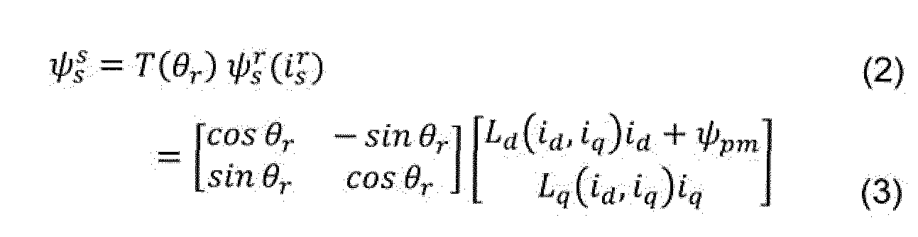 woraus sich unter Kenntnis der Parameter Widerstand Rs und absoluter q-Induktivität Lq aus der Zeitverläufe von Strom und Spannung bei mittleren und hohen Drehzahlen die Rotorlage 9r berechnen lässt, z.B mitels folgender Rechenvorschrift
 Fundamental wave methods use the general voltage equation of the machine Knowing the parameters of resistance R s and absolute q inductance L q, the rotor position 9 r can be calculated from the time profiles of current and voltage at medium and high speeds, for example using the following calculation rule
Dabei sind die sog. absoluten Induktivitäten Ld und Lq als Quotient aus Fiussverkettung (kurz Fluss) und Strom definiert und dadurch gekennzeichnet, dass sie im Subskript nur einen Achsenbezug (z.B. q) tragen The so-called absolute inductances L d and L q are defined as the quotient of flux linkage (flow for short) and current and are characterized in that they have only one axis reference (eg q) in the subscript

Anisotropie-basierte Verfahren nutzen den Hochfrequenz-Zusammenhang Anisotropy-based methods use the high-frequency relationship

Rotorlage-Schätzwert §r zuordnen
 Assign rotor position estimate to § r
Dabei sind die sog. differentiellen Induktivitäte und als Ableitung des The so-called differential inductances and as a derivative of the
Flusses nach dem Strom definiert und tragen zwei Achsenbezüge im Subskript
River defined by the current and bear two axis references in the subscript

In der Regel verläuft der Fluss über dem Strom nichtlinear, weshalb die WerteUsually the flow across the stream is non-linear, which is why the values
Häufig arbeiten Anisotropie-Verfahren jedoch mit Spannungsinjektion und werten dieHowever, anisotropy methods often work with voltage injection and evaluate that
Stromantwort aus, weshalb die inverse differentielle Induktivität relevant ist, die häufig vereinfacht als Admittanz Y bezeichnet wird Current response, which is why the inverse differential inductance is relevant, which is often simply referred to as admittance Y.

Hierin ist der sog. Anisotropiebetrag Y& die halbe Differenz zwischen der richtungsabhängig größten und kleinsten Admittanz Here the so-called anisotropy amount Y & is half the difference between the directionally largest and smallest admittance

Im unbestromten Zustand ist die Koppelkomponente näherungsweise Null, wodurch
 In the de-energized state, the coupling component is approximately zero, which means that
sich (18) vereinfacht zu
 simplified (18)
Der Anisotropiewinkel ()u ist die Richtung der kleinsten differentiellen Induktivität und folglich der größten Admittanz. Um ±90° (elektrisch) versetzt findet sich die Richtung der größten differentiellen Induktivität und folglich der kleinsten Admittanz. Der Aniso tropiewinkel kann deshalb aus beiden Größen äquivalent beispielsweise wie folgt berechnet werden The anisotropy angle () u is the direction of the smallest differential inductance and consequently the largest admittance. The direction of the largest differential inductance and consequently the smallest admittance is offset by ± 90 ° (electrical). The anisotropy angle can therefore be calculated from both variables, for example as follows

Weiterhin werden im Rahmen der hier beschriebenen Ausführungsformen hinsichtlich der Rotortopologie von Synchronmaschinen zwei Klassen unterschieden: Furthermore, two classes are distinguished within the scope of the embodiments described here with regard to the rotor topology of synchronous machines:
1.
 Synchronmaschinen haben einen Rotorquerschnitt, in dem sich die Menge und Form des weichmagnetischen Materials zwischen den verschiedenen Magnetpfaden der Phasenwickiungen nicht unterscheidet, so- dass ihre magnetische Anisotropie sich ausschließlich dadurch begründet, dass das erregende Element (z.B. Permanentmagnet oder Erregerwicklung) das weichmagnetische Material lokal (d.h. richtungsabhängig) sättigt. Die magneti sche Anisotropie dieser Maschinen im unbestromten Zustand ist meist kleiner, nämlich1. Synchronous machines have a rotor cross-section in which the amount and shape of the soft magnetic material do not differ between the different magnetic paths of the phase windings, so that their magnetic anisotropy is based solely on the fact that the exciting element (e.g. permanent magnet or excitation winding) localizes the soft magnetic material ( depending on the direction). The magnetic anisotropy of these machines in the de-energized state is usually smaller, namely
2.
 Synchronmaschinen zeigen einen Rotorquerschnitt, in dem sich die Menge und/oder Form des weichmagnetischen Materials zwischen
den verschiedenen Magnetpfaden der Phasenwicklungen unterscheidet, was eine zusätzliche anisotrope Komponente erzeugt. Die magnetische Anisotropie dieser Maschinen im unbestromten Zustand ist dadurch meist größer, nämlich
Synchronmaschinen zeigen einen Rotorquerschnitt, in dem sich die Menge und/oder Form des weichmagnetischen Materials zwischen
den verschiedenen Magnetpfaden der Phasenwicklungen unterscheidet, was eine zusätzliche anisotrope Komponente erzeugt. Die magnetische Anisotropie dieser Maschinen im unbestromten Zustand ist dadurch meist größer, nämlich
 2nd Synchronous machines show a rotor cross-section in which the amount and / or shape of the soft magnetic material between distinguishes the different magnetic paths of the phase windings, which creates an additional anisotropic component. As a result, the magnetic anisotropy of these machines in the de-energized state is usually greater, namely
Fig. 1 zeigt links ein typisches Beispiel für eine geometrisch isotrope Maschine und rechts ein typisches Beispiel für eine geometrisch anisotrope Maschine. Nur die schraffierten Bereiche haben eine hohe magnetische Leitfähigkeit und führen aufgrund der Geometrie des rechten Querschnitts bei diesem zu einer deutlich erhöhten Induktivität in q-Richtung. 1 shows a typical example of a geometrically isotropic machine on the left and a typical example of a geometrically anisotropic machine on the right. Only the hatched areas have a high magnetic conductivity and, due to the geometry of the right cross section, lead to a significantly increased inductance in the q direction.
Unabhängig von der tatsächlichen Geometrie ist eine Zuweisung der meisten Maschi- nen in ihre entsprechende Klasse auf Basis des Klemmverhaltens möglich, wenn die initial Vorgefundene Anisotropie gegen den Schwellwert 20% verglichen wird. Regardless of the actual geometry, most machines can be assigned to their corresponding class on the basis of the clamping behavior if the initially found anisotropy is compared against the threshold value 20%.
3 Sättigungsannahmen 3 saturation assumptions
Im Folgenden wird ein Verfahren zur lastfreien Bestimmung lastabhängiger Lagezuordnungsparameter einer Synchronmaschine ohne Lagegeber vorgestellt. Die Synchronmaschine wird über getaktete Klemmspannungen angesteuert, aus denen in Verbin- dung mit der gemessenen Stromantwort die Induktivität bzw. Admittanz berechnet wird. Alternativ zu dieser Berechnung kann die lastfrei kleinste und die lastfrei größte diffe rentielle Induktivität und auch bekannt sein. Aus der lastfrei kleinsten und

 A method for the load-free determination of load-dependent position assignment parameters of a synchronous machine without a position encoder is presented below. The synchronous machine is controlled via clocked clamping voltages, from which the inductance or admittance is calculated in connection with the measured current response. As an alternative to this calculation, the smallest load-free and the largest load-free differential inductance can also be known. From the smallest and the most
der lastfrei größten differentiellen Induktivität und und dem Kurzschiuss-

 the largest load-free differential inductor and and the short-circuit
strom wird das magnetische Sättigungsverhalten unter Last der absoluten Indukti-
 current the magnetic saturation behavior under load of the absolute inductance
vität und der magnetischen Anisotropie der Synchronmaschine vorhergesagt und im Lagegeber-losen Regelungsbetrieb kompensiert und/oder zur Lagezuordnung genutzt. and the magnetic anisotropy of the synchronous machine are predicted and compensated for in position-less control mode and / or used for position assignment.
In manchen Ausführungsformen entspricht eine lastfreie differentielle Induktivität der Ableitung der Flussverkettung nach dem Strom (vgl. (10)-(12>) im Betriebspunkt mit Null Strom.
In manchen Ausführungsformen sind die kleinste und die größte differentielle Induktivi- tät der richtungsanhängig kleinste und größte differentielle Induktivitätswert eines Betriebspunktes, wobei die Richtungsabhängigkeit der magnetischen Anisotropie entspricht. In some embodiments, a load-free differential inductance corresponds to the derivative of the flux linkage after the current (cf. (10) - (12>) at the operating point with zero current. In some embodiments, the smallest and the largest differential inductance are the direction-dependent smallest and largest differential inductance values of an operating point, the directional dependency corresponding to the magnetic anisotropy.
Wenn die lastfrei kleinste und die lastfrei größte differentielle Induktivität Ldd0 und Lqq0 nicht bekannt sind, können diese Werte durch elektrische Anregung der Maschinen aus dem Strom-Spannungs-Zusammenhang berechnet werden. Die Anregung können beispielsweise Testpulse, sinusförmige Spannungsverläufe oder ein zeitdiskretes Span- nungs-lnjektionsmuster sein. Zur Berechnung finden sich leicht verschiedene Ansätze, die üblicherweise die Spannungsanregung und die Stromantwort (z.B. Stromamplitude oder Stromdifferenz pro Zeitintervall) ins Verhältnis setzten. Bei Anisotropie-Verfahren mit zeitdiskretem Injektionsmuster [31] [32] zum Beispiel können der Anisotropie- Be trag UD und der isotrope Anteil US interne Rechengrößen sein, aus deren Werten und der isotrope Anteil bei Nullstrom und die Induktivitäten beispiels


 If the smallest load-free and the largest load-free differential inductance L dd0 and L qq0 are not known, these values can be calculated from the current-voltage relationship by electrical excitation of the machines. The excitation can be, for example, test pulses, sinusoidal voltage profiles or a discrete-time voltage injection pattern. There are easily different approaches to the calculation, which usually relate the voltage excitation and the current response (eg current amplitude or current difference per time interval) in relation. For anisotropy methods with a time-discrete injection pattern [31] [32], for example, the anisotropy amount U D and the isotropic component U S can be internal calculation variables, from their values and the isotropic component at zero current and the inductances, for example
weise wie folgt berechnet werden können can be calculated as follows

Aber auch beliebige andere Vorschriften zur Berechnung einer differentiellen Induktivität können verwendet werden, um die Werte
 und
und
 als Grundlage für das in diesem Dokument beschriebene Verfahren und/oder für die beschriebenen Ausführungs- formen zur Verfügung zu stellen. But any other rules for calculating a differential inductance can also be used to measure the values and to provide as a basis for the method described in this document and / or for the described embodiments.
Auch wenn differentielle Induktivitäten nur für Anisotropie-Verfahren direkt wirksam sind, werden sie in manchen Ausführungsformen ebenfalls zur Parametrierung von Grundwellenverfahren genutzt. Even if differential inductances are only directly effective for anisotropy methods, in some embodiments they are also used to parameterize fundamental wave methods.
Der Kurzschlussstrom ist allgemein ein zur Erregung durch den Permanentmagnet
 The short circuit current is generally one for excitation by the permanent magnet
(PM) (oder durch die Erregerwicklung) äquivalenter Strombetrag, der beispielsweise
■ in negativer d-Richtung eingeprägt zur Auslöschung der Flussverkettung
 führt, oder (PM) (or through the excitation winding) equivalent amount of current, for example ■ Embossed in negative d direction to extinguish the river chain leads, or
■ sich einstellt, wenn die Welle bei Kurzschluss der Klemmen (Null Spannung) schnell (z.B. Nenndrehzahl) angetrieben, oder ■ occurs when the shaft drives quickly (eg nominal speed) in the event of a short circuit in the terminals, or
■ nach einem zu den vorgenannten Methoden physikalisch äquivalenten Prinzip bestimmt wird, oder Is determined according to a principle that is physically equivalent to the aforementioned methods, or
« der mit einer der nachfolgenden Berechnungsvorschriften im Rahmen der vorgestellten Sättigungsannahme ermittelt wird. « Which is determined using one of the following calculation rules as part of the saturation assumption presented.
Aber auch beliebige andere Vorschriften zur Berechnung eines zur Erregung durch den PM (oder die Erregerwicklung) äquivalenten Strombetrags können verwendet werden, um den Wert des Ku rzschl ussstroms für das in diesem Dokument beschriebene
 However, any other rules for calculating an amount of current equivalent to the excitation by the PM (or the field winding) can be used to determine the value of the short-circuit current for that described in this document
Verfahren und/oder für die beschriebenen Ausführungsformen zur Verfügung zu stel len. To provide methods and / or for the described embodiments.
Die grundlegende Idee der Sättigungsannahme und aller ihrer Ausführungsformen ist, dass im unbestromten Zustand die Maschine in d-Richtung durch den PM in einem bestimmten Grad gesättigt und in q-Richtung ungesättigt ist und dass in q-Richtung der gleiche Grad an Sättigung vorliegen wird, wenn in q-Richtung der Kurzschlussstrom ipm eingeprägt wird. Konkret unterliegt manchen A u sf ü h ru n gsf ormen die Annahme, dass die q-Achse (Richtung quer zum PM) das gleiche magnetische Verhalten an- nimmt, wie die d -Achse (Richtung des PM) im unbestromten Zustand, wenn in q-Rich tung der Kurzschlussstrom eingeprägt wird.The basic idea of the saturation assumption and all of its embodiments is that in the de-energized state the machine is saturated to a certain degree in the d-direction by the PM and unsaturated in the q-direction and that the same degree of saturation will be present in the q-direction, if the short-circuit current i pm is impressed in the q direction. Specifically, some designs are subject to the assumption that the q-axis (direction perpendicular to the PM) assumes the same magnetic behavior as the d -axis (direction of the PM) in the de-energized state when in q direction the short-circuit current is impressed.
Fig. 2 zeigt qualitativ einen beispielhaften Strom-Fluss-Zusammenhang in d-Richtung, welcher aufgrund der Sättigung des weichmagnetischen Materials eine gekrümmte Form aufweist. Ohne d-Strom id = 0 gleicht der Fluss dem PM-Fluss h und der
 2 shows qualitatively an exemplary current-flow relationship in the d direction, which has a curved shape due to the saturation of the soft magnetic material. Without d-current i d = 0, the flow is the same as the PM flow h and the
Anstieg (angedeutet durch die gestrichelte Tangente mit Anstiegs-Dreieck) gleicht der differentiellen d-lnduktivität im unbestromten Zustand ist der
 The rise (indicated by the dashed tangent with the rise triangle) is equal to the differential d inductance in the de-energized state
Fluss ausgelöscht i}>d ~ 0, das Eisen folglich ungesättigt und gemäß Sättigungsan nahme der Anstieg der Flusskurve gleich der differentiellen q-Induktivität im unbestrom- ten ZustanFlow extinguished i}> d ~ 0, the iron consequently unsaturated and, according to the saturation assumption, the rise in the flow curve equals the differential q inductance in the de-energized state

Auf Basis dieser Daten
 kann nun im Rahmen der Sättigungsannahme der Kurzschlussstrom
 m wie folgt berechnet werden. In Fig. 2 ist ersichtlich, dass für d-Ströme zwischen
 alle Anstiegswerte zwischenBased on this data can now within the scope of the saturation assumption the short-circuit current m can be calculated as follows. In Fig. 2 it can be seen that for d-currents between all increase values between
gig variieren kann. gig can vary.
In manchen Ausführungsformen wird nun der Kurzschlussstrom
 p als Quotient aus der Erreger- bzw. PM-Flussverkettung geteilt durch eine Kombination der lastfrei
 In some embodiments, the short circuit current is now p as the quotient from the excitation or PM flow chaining divided by a combination of the load-free
kleinsten und der lastfrei größten differentiellen Induktivität
 und
und
 berechnet. Diese Berechnung kann beispielsweise wie folgt erfolgen
 wobei mittels und der Einfluss der jeweiligen Induktivität gewichtet werden kann.smallest and the load-free largest differential inductance and calculated. This calculation can be carried out as follows, for example whereby the influence of the respective inductance can be weighted by means of and.
In manchen Ausführungsformen entspricht die Kombination einer Mittelwertbildung, beispielsweise mit den Koeffizienten Dazu wird beispielsweise angenom-
 In some embodiments, the combination corresponds to averaging, for example with the coefficients.
men, dass der mittlere Anstieg dem Mittelwert der Randanstiege gleichtthat the mean increase equals the mean of the edge increases

sodass wie folgt berechnet werden kannso that can be calculated as follows

Alternativ kann der Kurzschlussstrom beispielsweise durch einen Kurzschlussver
 Alternatively, the short-circuit current can, for example, by a short-circuit ver
such bestimmt werden. Unabhängig von seiner Bestimmung ist der Kurzschlussstrom ipm ein Schlüsselparameter für die nun folgenden Berechnungen von Parametern für Grundwellenverfahren in Abschnitt 3.1 und für Anisotropie-Verfahren in Abschnitt 3.2 und 3.3.
Die vorgestellten Berechnungsansätze der Parameter für Anisotropie-Verfahren sind vorzugsweise auf geometrisch isotrope Maschinentypen anwendbar. Deshalb findet in machen Ausführungsformen eine Kompensation und/oder Nutzung zur Lagezuordnung der Anisotropie-Sättigungsberechnungen nur dann statt, wenn die Differenz zwischen der lastfrei größten und der lastfrei kleinsten differentiellen Induktivität weniger als 20% ihrer Summe beträgt. to be determined. Regardless of its determination, the short-circuit current i pm is a key parameter for the following calculations of parameters for fundamental wave methods in section 3.1 and for anisotropy methods in sections 3.2 and 3.3. The presented calculation approaches for the parameters for anisotropy methods are preferably applicable to geometrically isotropic machine types. Therefore, in some embodiments, compensation and / or use for the location assignment of the anisotropy saturation calculations only takes place if the difference between the no-load largest and the no-load differential inductance is less than 20% of their sum.
3.1 Grundwelleninduktivität 3.1 fundamental wave inductance
Ein Parameter von Grundwellenverfahren, der zur Berücksichtigung von Sättigung stromabhängig hinterlegt wird, ist beispielsweise die absolute Induktivität in q-RichtungOne parameter of fundamental wave methods that is stored depending on the current to take account of saturation is, for example, the absolute inductance in the q direction
V ln manchen Ausführungsformen wird die absolute Induktivität Lq als Parameter zur Auswertung der induzierten Spannung so berechnet, dass sie ausgehend von ihrem bei Null Strom geltenden Wert, der lastfrei größten differentiellen Induktivität mit
 zunehmendem Strom so absinkt, dass sie bei Erreichen des Kurzschlussstroms ( )
 dem Mittelwert der lastfrei kleinsten und größten differentiellen Induktivität ( L i t0 und Iw o) gleicht. V In some embodiments, the absolute inductance Lq is calculated as a parameter for evaluating the induced voltage in such a way that, based on its value valid at zero current, it also has the largest differential-free inductance without load increasing current so that when the short-circuit current is reached () is equal to the mean value of the smallest and largest differential inductance (L i t0 and Iw o).
Fig. 3 zeigt einen beispielhaften Strom-Fluss-Zusammenhang in q-Richtung, der sich für eine geometrisch isotrope Maschine gleich zu dem der d-Richtung ergibt - mit dem Unterschied, dass die Kurven zueinander derart horizontal verschoben sind, dass die q-Kurve punktsymmetrisch durch den Ursprung und die d-Kurve durch -tprn verläuft. 3 shows an exemplary current-flow relationship in the q direction, which for a geometrically isotropic machine is the same as that in the d direction - with the difference that the curves are shifted horizontally relative to one another in such a way that the q curve symmetrically through the origin and the d-curve runs through -tprn.
Gemäß obiger Sättigungsannahme dem die folgenden Ausführungsbeispiele unterlie gen, erreicht wenn wo dann ebenfalls der Anstieg ist.According to the above saturation assumption, the following exemplary embodiments are subject to when reached where the rise is also.
Die absolute Induktivität Lq trägt jedoch einen von Lqq verschiedenen Wert, wie die ge punkteten Linien veranschaulichen. However, the absolute inductance Lq has a value different from Lqq, as the dotted lines illustrate.
Um von den (möglicherweise Injektions-basiert gemessenen) differentiellen Induktivitä- ten und auf den Verlauf der absoluten Induktivität ) zu schlussfolgern,

 wird beispielsweise zunächst angenommen, dass der Verlauf der differentiellen Indukti vität Lqqiiq) linear und symmetrisch L istIn order to conclude from the (possibly injection-based measured) differential inductances and on the course of the absolute inductance), For example, it is initially assumed that the course of the differential inductivity L q qii q ) is linear and symmetrical L.

Gemäß (11 ) ergibt sich beispielsweise per IntegrationAccording to (11), this results, for example, by integration


0 ergibt (29) und entspricht damit dem Fakt, dass für Nullstrom die differenti
 0 results in (29) and thus corresponds to the fact that the differenti for zero current
elle und die absolute Induktivität gleich sind. elle and the absolute inductance are the same.
Beispielsweise mit diesem linearen Gesetz (29) bzw. (30)-(31 ) kann basierend auf den initial mess- und/oder berechenbaren Parametern und die Sättigung des

 For example, with this linear law (29) or (30) - (31) based on the initially measurable and / or calculable parameters and the saturation of the
zentralen Grundwellenparameters Lq approximiert werden. Diese Approximation trifft bei geometrisch isotropen Maschinen gut zu. Bei geometrisch anisotropen Maschinen ist diese Approximation zwar mit Fehlern im konservativen Bereich behaftet - d.h. die
Sättigung wird zu schwach kompensiert weil das Sätigungsverhalten des weichmagnetischen Materials in q-Richtung nicht aus der d-Richtung abgeleitet werden kann, aber dennoch anwendbar. central fundamental wave parameter L q can be approximated. This approximation applies well to geometrically isotropic machines. In the case of geometrically anisotropic machines, this approximation is subject to errors in the conservative range - that is, the Saturation is compensated too weakly because the actuation behavior of the soft magnetic material in the q direction cannot be derived from the d direction, but can still be used.
Eine Kompensation gemäß dieser Approximation ist besser als keine Kompensation anzuwenden. Daher kann das Gesetz für die Stromabhängigkeit der Grundwellenin- duktivität (29) bzw. (30)~(31) auf alle PM-Maschinen angewendet werden - für geomet risch isotrope, wie auch für geometrisch anisotrope. Compensation according to this approximation is better than no compensation. Therefore, the law for the current dependence of the fundamental inductance (29) or (30) ~ (31) can be applied to all PM machines - for geometrically isotropic as well as for geometrically anisotropic.
3.2 Anisotropieverschiebung 3.2 Anisotropy shift
Die Anisotropie von geometrisch isotropen Maschinen ist hervorgerufen durch lokaleThe anisotropy of geometrically isotropic machines is caused by local ones
Sättigung des weichmagnetischen Materials, welche im unbestromten Zustand in PM- Richtung maximal ist. Dann ist die Anisotropie mit dem Rotor ausgerichtet und läuft bei Drehung näherungsweise mit ihm um. Unter Einprägung eines Drehmoment-bildenden Stroms zeigt sich eine relative Verschiebung zwischen Rotor und Anisotropie, weil der quer zum PM ausgerichtete Strom den Sättigungszustand beeinflusst. Saturation of the soft magnetic material, which is maximum in the non-energized state in the PM direction. Then the anisotropy is aligned with the rotor and rotates approximately with it when rotating. When a torque-generating current is impressed, a relative shift between the rotor and anisotropy is shown, because the current oriented transversely to the PM influences the saturation state.
In manchen Ausführungsformen wird ein Sättigungsstromvektor durch vektorielle Addi- tion des Phasenstromvektors und des Kurzschlussstromvektors berechnet, wobei der Kurzschlussstromvektor den Betrag des Kurzschlussstroms hat und in Richtung des PM ausgerichtet ist. In some embodiments, a saturation current vector is calculated by vectorially adding the phase current vector and the short-circuit current vector, the short-circuit current vector having the magnitude of the short-circuit current and oriented in the direction of the PM.
In der folgenden beispielhaften Beschreibung der Ausführungsform ist der Sättigungs stromvektor durch ft , der Phasenstromvektor durch ft und der Kurzschlussstromvek-
 In the following exemplary description of the embodiment, the saturation current vector by ft, the phase current vector by ft and the short-circuit current vector
tor durch repräsentiert - jeweils in Statorkoordinaten ausgedrückt (Superskript s). Die gleichen Vektoren in Rotorkoordinaten dargestellt sind , ft und ftgate represented by - each expressed in stator coordinates (superscript s). The same vectors are represented in rotor coordinates, ft and ft
Der Kurzschlussstrom und der Strom in der Stators ick lung
 überlagern sich nun
 The short-circuit current and the current in the stator development overlap now
beispielsweise linear und die Summe ergibt den Sättigungsstromfor example linear and the sum gives the saturation current


Damit ergibt sich die sog. Anisotropieverschiebung 0lir , d.h. die Verschiebung des Anisotropiewinkels relativ zum Rotor (bzw. der Anisotropiewinkel in Rotorkoordinaten), nach der Ausrichtung des Sättigungsstroms in Rotorkoordinaten
 This results in the so-called anisotropy shift 0 lir, ie the shift in the anisotropy angle relative to the rotor (or the anisotropy angle in rotor coordinates) after the saturation current has been aligned in rotor coordinates

So wird in machen Ausführungsformen die Anisotropieverschiebung als Parameter
 Thus, in some embodiments, the anisotropy shift is used as a parameter
zur Auswertung der magnetischen Anisotropie so berechnet, dass sie mit zunehmendem Phasenstrom so anwächst, dass die damit angenommene Ausrichtung der-Aniso- tropie der Richtung des Sättigungsstromvektors entspricht for evaluating the magnetic anisotropy, it is calculated so that it increases with increasing phase current in such a way that the assumed orientation of the anisotropy corresponds to the direction of the saturation current vector
Fig. 4 zeigt beispielhaft, wie der Kurzschlussstrom und der Statorstrom in Rotor

 4 shows an example of how the short-circuit current and the stator current in the rotor
koordinaten vektoriell addiert werden, woraus sich der Sättigungsstrom
 ί ergibt, des- sen Ausrichtung in Rotorkoordinaten bei geometrisch isotropen Maschinen der Aniso- tropieverschiebung gleicht.coordinates are added vectorially, resulting in the saturation current ί results in the alignment in rotor coordinates of geometrically isotropic machines being the same as the anisotropy shift.
Dieser Verschiebungswinkel
 wird beispielsweise im Betrieb unter Last vom gemes- senen Anisotropiewinkel
 (Ergebnis der Anisotropie-Identifikation, z.B. eines der Verfahren [6] [7] [8] [31]) subtrahiert, um die geschätzte Rotorlage zu erhalten
 This shift angle is, for example, in operation under load from the measured anisotropy angle (Result of the anisotropy identification, eg one of the methods [6] [7] [8] [31]) subtracted in order to obtain the estimated rotor position
Weil bei geometrisch isotropen Maschinen die sog. Maximum-Torque-per-Ampere (MTPA) Solistrom-T rajektorie nahezu auf der q-Achse liegt werden diese Maschinen im unteren Drehzahlbereich meist ohne d-Sollstromanteil betrieben. Damit lässt sich (35) vereinfachen zu

 Because in geometrically isotropic machines the so-called maximum torque-per-ampere (MTPA) solistream trajectory is almost on the q-axis, these machines are usually operated in the lower speed range without a d-nominal current component. This can be simplified (35)
Letztere lineare Approximation (38) verhält sich beispielsweise im BereichThe latter linear approximation (38) behaves for example in the area
tendenziell konservativ (keine Überkompensation) mit Approximationsfehlern bis klei ner 3,7°, wobei sie rechensparsamer ist als (37), insbesondere weil der Faktor tends to be conservative (no overcompensation) with approximation errors up to less than 3.7 °, whereby it is more computationally economical than (37), especially because of the factor
3.3 Parameter für eindeutige Anisotropie-Rotorlage-Zuordnung 3.3 Parameters for clear anisotropy-rotor position assignment
Wird zusätzlich der Anisotropiebetrag in Abhängigkeit vom Sättigungsstrom
 In addition, the anisotropy amount depends on the saturation current
t einbezogen, kann aus den eingangs bekannten Werten /,d f0, iqqQ und ipm ebenfalls eine Vorschrift zur eindeutigen Rotorlagezuordnung abgeleitet werden. Including t , a rule for unambiguous rotor position assignment can also be derived from the values known at the beginning /, d f0 , i qqQ and i pm .
In manchen Ausführungsformen wird der Anisotropiebetrag KD als Parameter zur ein deutigen Anisotropie-Rotorlagezuordnung so berechnet, dass er ausgehend von sei nem bei Nullstrom wirksamen Wert über dem Sättigungsstrombetrag progressiv an wächst In some embodiments, the anisotropy amount K D is calculated as a parameter for a clear anisotropy rotor position assignment in such a way that it increases progressively from its value effective at zero current above the saturation current amount

Dabei wird gemäß (40) in manchen Ausführungsformen der bei Nullstrom wirksameAccording to (40), the effective at zero current becomes effective in some embodiments
Wert des Anisotropiebetrags aus den lastfreien differentiellen InduktivitätenValue of the anisotropy amount from the load-free differential inductors

Ein progressiver Verlauf bedeutet konkret, dass der Anstieg von fA(x) für positive Argu mente x stets positiv ist und mit größer werdendem Argument ansteigt In concrete terms, a progressive course means that the increase in f A (x) for positive arguments x is always positive and increases with increasing arguments


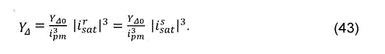
In manchen Ausführungsformen entspricht das progressive Anwachsen des Anisotro- piebetrags einem Anwachsen proportional zur dritten Potenz des Sättigungsstrombetrags Dies wird beispielsweise durch die folgende Formel repräsentiert:
 In some embodiments, the progressive increase in the anisotropy amount corresponds to an increase proportional to the third power of the saturation current amount. This is represented, for example, by the following formula:
Aus Anisotropiebetrag und Anisotropieausrichtung lässt sich ein beispielhafter Anisotropievektor konstruieren
 in welchem alle Variablen UD und 0 ! vom Sättigungsstromvektor
 f abhängen. Im Un- terschied zu (37) kann für die Herleitung der eindeutigen Rotorlagezuordnung nun je- doch nicht angenommen werden, dass der d-Stromanteil Null ist
 An anisotropy vector can be constructed from the anisotropy amount and anisotropy orientation in which all variables U D and 0 ! from the saturation current vector f depend. In contrast to (37), it cannot be assumed for the derivation of the unique rotor position assignment that the d-current component is zero
und es wird beispielsweise nicht die Anisotropieverschiebung relativ zum Rotorand it does not, for example, the anisotropy shift relative to the rotor

Fig 6 zeigt beispielhaft wie sich in (47) der Kurzschlussstrom i6 shows an example of how the short-circuit current i in (47)
was (43) und (47) begründet. which justifies (43) and (47).
Mit (
 kann der Anisotropievektor yA nun also beispielsweise als Funktion vom Strom in Statorkoordinaten tf und der Rotorlage Qr ausgedrückt wer- den With ( the anisotropy vector y A can now be expressed, for example, as a function of the current in stator coordinates tf and the rotor position Q r

was gemäß [33] die Grundlage zur Berechnung einer eindeutigen Rotorlagezuord nungsvorschrift ist. which, according to [33], is the basis for calculating a clear rotor position assignment rule.
In manchen Ausführungsformen wird also ein Modell-Anisotropievektor
 konstruiert, der die Länge des Anisotropiebetrags {YA) hat und im zweifachen Anisotropiewinkel (2qa) ausgerichtet ist, wobei der Anisotropiewinkel (qa) der Summe aus Rotorlage (0r) und Anisotropieverschiebung ( qίIT ) entspricht, sodass der Modell-Anisotropievektor als Funktion von Phasenstromvektor (i*) und Rotorlage (0r) beschrieben ist. Dieser Mo- dell-Anisotropievektor ist dann beispielsweise durch repräsentiert.So in some embodiments, a model anisotropy vector constructed which has the length of the Anisotropiebetrags {Y A) and is aligned in two-fold anisotropy angle (2q a), wherein the anisotropy angle corresponds to (q a) the sum of rotor position (0 r) and Anisotropieverschiebung (q ίIT) so that the model Anisotropy vector as a function of phase current vector (i *) and rotor position (0 r ) is described. This model anisotropy vector is then represented by, for example.
Im Folgenden werden zwei Ausführungsbeispiele beschrieben, die (49) in eine eindeu- tige Lagezuordnungsvorschrift ( überführen.Two exemplary embodiments are described below, which convert (49) into a unique position assignment rule ().
3.3.1 Lineare Lagezuordnung 3.3.1 Linear position assignment
In manchen Ausführungsformen wird die Lageabhängigkeit des Modell-Anisotropievek tors für verschiedene statorfeste Stromwerte im Sollstrom-Arbeitsp u nkt linearisiert und
eine lineare Lagezuordnungsvorschrift verwendet, die einer Projektion des gemesse- nen Anisotropievektors
 auf die für den gemessenen Strom geltende Linearisierung entspricht. In some embodiments, the positional dependence of the model anisotropy vector is linearized for various stator-fixed current values in the target current working point uses a linear position assignment rule, which is a projection of the measured anisotropy vector corresponds to the linearization applicable to the measured current.
Dazu wird die Abhängigkeit der Funktion (49) von der Rotorlage ()r unter der Randbe dingung eines unveränderten Stroms in Statorkoordinaten if = const. (die sog. SFC- Trajektorie) im Sollstrom-Arbeitspunkt linearisiert. For this purpose, the dependency of the function (49) on the rotor position () r under the boundary condition of an unchanged current in stator coordinates if = const. (the so-called SFC trajectory) linearized in the target current operating point.
Wie zuvor erwähnt, liegt bei geometrisch isotropen Maschinen der Sollstrom-Arbeits punkt auf der q-Achse
 As previously mentioned, in geometrically isotropic machines, the target current operating point lies on the q axis
Um diesen Arbeitspunkt kann (50) mittels der virtuellen Verschiebung h (kleiner Wert, z.B. 1°) linearisiert werden Around this working point (50) can be linearized using the virtual shift h (small value, e.g. 1 °)

worin mA s der Anstieg und yf0 der Offset der Gerade ist, welche (49) im und nahe um den Arbeitspunkt beschreibt
 where m A s is the rise and yf 0 is the offset of the straight line that describes (49) in and near the working point
Aus diesen linearisierten Parametern ml und yj0 kann nun eine beispielhafte lineareAn exemplary linear one can now be made from these linearized parameters ml and yj 0
Lagezuordnungsvorschrift abgeleitet werden
 die einer Projektion des gemessenen Anisotropievektors auf die Ge
 Location assignment rule can be derived that of a projection of the measured anisotropy vector onto the Ge
rade mit Übernahme des zugehörigen Winkelwerts entspricht.rade with transfer of the associated angle value.

Diese lässt sich beispielsweise im Rahmen dieser Sättigungsannahme vereinfacht be rechnen, indem aus (49) für Stromwinkel und ausge-

 wertet wird This can be calculated in a simplified manner, for example within the framework of this saturation assumption, by using (49) for the current angle and is evaluated

Aus (51) und (52) bzw. (58) und (59) kann nun eine beispielhafte lineare Lagezuord- nungsvorschrift abgeleitet werden An exemplary linear position assignment rule can now be derived from (51) and (52) or (58) and (59)

Betrieb zu abzuarbeiten. Dabei sind die Koeffizienten kx, ky und fc0 hinterlegte Modell- parameter und und das aktuelle Ergebnis der Strommessung und Anisotro-

 To process operation. The coefficients k x , k y and fc 0 are stored model parameters and and the current result of the current measurement and anisotropy
pie-ldentifikation im Betrieb.
ln manchen Ausführungsformen werden die Lagezuordnungskoeffizienten kx, ky und k0 nur einmal nach der initialen Ermittlung der Induktivitäten Ldd0 , Lqqü und des PM-Pie identification in operation. In some embodiments, the location assignment coefficients k x , k y and k 0 are determined only once after the initial determination of the inductances L dd0 , L qqü and the PM-
Flusswerts i(>pm (bzw. des Kurzschiussstroms ipm) für mehrere q-Stromwerte mittels (58H62), (48) und (25) berechnet und als Tabelle über dem Strom abgelegt. Dann ge- nügt es, im Betrieb die zum aktuellen Stromwert passenden Koeffizienten ) zu
 Flow value i (> pm (or the short-circuit current i pm ) for several q-current values is calculated using (58H62), (48) and (25) and stored as a table above the current. Then it is sufficient to operate the current current Current value matching coefficients)
wählen/interpolieren und mittels (63) die Rotorlage zuzuordnen. select / interpolate and assign the rotor position using (63).
3.3.2 Suchansatz 3.3.2 Search approach
In manchen Ausführungsformen wird dem Anisotropiemodell (beispielsweise
 bzw
bzw
 der gemessene Strom und ein variabler Rotorlage-Schätzwert (
 geführt, wobei dieser Schätzwert so variiert wird dass das Modell bestmöglich mit dem aktuellen Anisotropiemesswert (beispielsweise
 bzw. >D) übereinstimmt. In some embodiments, the anisotropy model (e.g. respectively the measured current and a variable rotor position estimate ( This estimate is varied in such a way that the model best matches the current anisotropy measurement (e.g. or> D ) matches.
Dafür kann zur Lagezuordnung im Betrieb beispielsweise der Punkt der SFC Modell- trajektorie y£ (i|S) gesucht werden, der dem Messwert ή naheliegt und der zugehörige
 For this purpose, the point of the SFC model trajectory y £ (i | S ), which is close to the measured value und and the associated one, can be searched for, for example, for the location assignment in operation
Lagewert als Schätzwert verwendet werden. Beispielsweise wird in Anlehnung an (58) das auf (48) basierende Modell nun mit variablem Rotorlagewert $r betrachtet

 Position value can be used as an estimate. For example, based on (58), the model based on (48) is now considered with a variable rotor position value $ r
wobei q( und i\} im Betrieb Messwerte sind und er so variiert wird, dass das Modell bestmöglich mit dem aktuellen Messwert y übereinstimmt. In manchen Ausführungs-
 where q ( and i \ } are measured values during operation and e r is varied so that the model matches the current measured value y as closely as possible.
formen entspricht das Variieren zur bestmöglichen Übereinstimmung einer Minimierung des Abstandes zwischen Modellwert und Messwert
 Shaping corresponds to varying to best match a minimization of the distance between the model value and the measured value
Anschließend kann die gefundene Extremstelle als Schätzwert §r übernommen werden. Zur Minimierung kann beispielsweise ein Gradientenabstiegsverfahren genutzt werden
 worin der Vorfaktor fe · beispielsweise abhängig von der Lageabhängigkeit die
 The extreme point found can then be adopted as an estimated value § r . For example, a gradient descent method can be used to minimize it where the prefactor fe · depends on the position dependency
Bandbreite der Nachführung von §r skalieren kann. Bandwidth of the tracking of § r can scale.
4 Experimentelle Ergebnisse 4 Experimental results
Fig. 7a-f verifiziert die Sättigungsannahmen für die Grundwelleninduktivität und die Anisotropie-Verschiebung anhand dreier geometrisch isotroper (SPM) und dreier geometrisch anisotroper (1PM) Synchronmaschinen von 6 verschiedenen Herstellern mit unterschiedlichen Werten für Nennleistung und Anisotropie-Verhältnis (SR). Die verti- kalen gepunkteten Linien, welche Nennlast markieren, setzen den dargestellten Überlastbereich und den Punkt mit Kurzschlussstrom (<q/ipm = 1) in Relation. 7a-f verify the saturation assumptions for the fundamental wave inductance and the anisotropy shift using three geometrically isotropic (SPM) and three geometrically anisotropic (1PM) synchronous machines from 6 different manufacturers with different values for nominal power and anisotropy ratio (SR). The vertical dotted lines, which mark the nominal load, relate the overload range shown and the point with short-circuit current (< q / i pm = 1).
Die durch die Grundwelleninduktivität verursachten Schätzfehler sind bei allen Maschi- nen unter Verwendung der Sättigungsannahme deutlich verringert gegenüber dem Be- trieb mit Vernachlässigung der Sättigung, d.h. mit konstantem Parameter Lq. Für alle SPMs überschreitet jener Schätzfehler in praxisrelevantem Rahmen von vierfacher Überlast eine Fehlerschwelle von 5° elektrisch nicht, während mit konstantem Lq bis zu 20° Fehler entstehen. Bei IPMs sind jene Schätzfehler größer (im dargestellten Lastbe- reich <10° elektrisch) als bei SPMs, aber dennoch deutlich geringer, als bei Betrieb mit konstantem Lq , Deshalb kann eine Verwendung der Sättigungsannahme der Grundwelleninduktivität auch bei geometrisch anisotropen Maschinen sinnvoll sein. The estimation errors caused by the fundamental wave inductance are significantly reduced in all machines using the saturation assumption compared to the operation with neglect of saturation, ie with constant parameter L q . For all SPMs, that estimation error does not exceed an error threshold of 5 ° electrically in a practical four-fold overload, while errors of up to 20 ° occur with constant L q . With IPMs, those estimation errors are larger (<10 ° electrical in the load range shown) than with SPMs, but nevertheless significantly less than when operating with constant L q. Therefore, using the saturation assumption of the fundamental wave inductance can also make sense for geometrically anisotropic machines.
Die durch die Anisotropie-Verschiebung verursachten Schätzfehler sind bei geometrisch isotropen Maschinen unter Verwendung der Sättigungsannahme deutlich verringert gegenüber dem Betrieb ohne Berücksichtigung der Sättigung, d.h. mit direkter Ver wendung des Anisotropiewinkeis als Rotorlagewert. Bei SPMs bleibt jener Schätzfehler mit Sättigungsannahme meist kleiner 7° elektrisch, während mit qίh. = 0 bis zu 60° Fehler entstehen. Jedoch ist mit SPM1 auch ein schwierigerer Fall dargestellt, wo der Schätzfehler auch mit Sättigungsannahme auf bis zu 15° ansteigt. Bei IPMs hingegen sind jene Anisotropie-Schätzfehler nicht nur deutlich größer als bei SPMs, sondern
auch häufig betragsmäßig größer, als bei direkter Verwendung des Anisotropiewinkeis als Rotorlagewert. Deshalb ist eine Verwendung der Sättigungsannahme für die Aniso- tropie-Verschiebung bei geometrisch anisotropen Maschinen nicht sinnvoll. The estimation errors caused by the anisotropy shift are significantly reduced in geometrically isotropic machines using the saturation assumption compared to operation without taking saturation into account, ie with direct use of the anisotropy angle as the rotor position value. In SPMs, that estimation error with saturation assumption usually remains less than 7 ° electrical, while with q ίh . = 0 up to 60 ° errors occur. However, SPM1 also represents a more difficult case where the estimation error also increases up to 15 ° with saturation assumption. In contrast, with IPMs those anisotropy estimation errors are not only significantly larger than with SPMs, but also also often larger in amount than when using the anisotropy angle as the rotor position value. It is therefore not sensible to use the saturation assumption for the anisotropy shift in geometrically anisotropic machines.
Fig. 8a-c vergleicht die experimentellen Ergebnisse aus dem geberlosen Betrieb mit der geometrisch isotropen Maschine SPM3 unter Parametrierung ohne Sättigungsan- nahme, mit Anisotropie-Verschiebungs-Annahme und mit Annahme zur eindeutigen Rotorlagezuordnung nach dem Ausführungsbeispiel in Abschnitt 3.3.1. In allen Fällen wurde SPM3 durch eine Lastmaschine langsam angetrieben und ihre Rotorlage aus- schließlich Anisotropie-basiert geschätzt und zur Transformation der Feldorientierten Stromregelung verwendet. Der q-Sollstrom wurde ab t = 0 langsam erhöht, sodass er bei ca. 0.6s Nennstrom und bei ca. 3s den Kurzschlussstrom ipm erreicht ist. Ohne Sättigungsannahme (Fig. 8a) wächst der mittlere (Flarmonische ausgeblendet) Schätzfeh- ier schnell an, überschreitet bereits bei Nennstrom 10° und der Regelkreis wird vor Erreichen des Kurzschlussstroms instabil. Mit der vorgestellten Annahme zur Anisotropie- Verschiebung (Fig. 8b) überschreitet der mittlere Schätzfehler erst bei ca. dreifachem Nennstrom die 10° Schwelle und ist damit auch bei höheren Drehmomenten noch für eine effiziente Stromregelung nutzbar. Aber auch in diesem Fall wird der Regelkreis vor Erreichen des Kurzschlussstroms instabil, weil der Zusammenhang zwischen Anisotro piewinkel und Rotorlage uneindeutig [34] wird. Mit der vorgestellten Annahme zur ein deutigen Rotorlagezuordnung (Fig. 8c) bleibt der mittlere Schätzfehler im gesamten Lastbereich kleiner als 10º und ist damit ohne Drehmomentbeschränkung für eine effi ziente Stromregelung nutzbar. Darüber hinaus wird der Regelkreis auch bei hohen Lasten nicht instabil, weil die in [34] beschriebenen Ursachen für diese Art der Zuordnung nicht gelten. In allen Fällen sind in der geschätzten Rotoriage und besonders im 8a-c compares the experimental results from the encoderless operation with the geometrically isotropic machine SPM3 under parameterization without assumption of saturation, with anisotropy displacement assumption and with assumption for the unique rotor position assignment according to the embodiment in section 3.3.1. In all cases, the SPM3 was driven slowly by a load machine and its rotor position was estimated exclusively based on anisotropy and used to transform the field-oriented current control. The q nominal current was slowly increased from t = 0, so that it is reached at approx.0.6s nominal current and at approx. 3s short-circuit current i pm . Without assumption of saturation (Fig. 8a), the middle (flarmonic masked) estimate increases quickly, exceeds 10 ° at nominal current and the control circuit becomes unstable before the short-circuit current is reached. With the assumption about the anisotropy shift presented (FIG. 8b), the average estimation error only exceeds the 10 ° threshold at approximately three times the nominal current and can therefore still be used for efficient current control even at higher torques. In this case, too, the control circuit becomes unstable before the short-circuit current is reached, because the relationship between the anisotropy angle and the rotor position becomes ambiguous [34]. With the assumption presented for a clear rotor position assignment (FIG. 8c), the mean estimation error remains less than 10 ° in the entire load range and can therefore be used for an efficient current control without torque limitation. In addition, the control loop does not become unstable even at high loads because the causes described in [34] do not apply to this type of assignment. In all cases are in the estimated rotoriage and especially in
Schätzfehler jedoch zwei- und sechs-periodische Oberwellen zu sehen, welche durch eine statorfeste und eine negative vierte Anisotropie-Harmonische [32] hervorgerufen werden, die im vorgestellten Verfahren nicht berücksichtigt werden. Eine zusätzliche Berücksichtigung dieser oder weiterer Harmonischer ist aber auch bei keiner der vorge- ste Ilten Ausführungsformen ausgeschlossen. However, there are two and six periodic harmonics, which are caused by a stator-fixed and a negative fourth anisotropy harmonic [32], which are not considered in the presented method. However, additional consideration of this or further harmonics is also not ruled out in any of the previous embodiments.
Weitere Aspekte betreffen: Other aspects concern:
(i) Eine Vorrichtung zur Steuerung und Regelung einer Drehfeldmaschine, umfassend einen Stator und einen Rotor, mit einem mit einer Einrichtung zur Erfassung einer
Anzahl von Phasenströmen und mit einem Controller zur Ansteuerung des PWM-Um- richters, der zur Durchführung des Verfahrens wie oben beschrieben eingerichtet und ausgebildet ist; und einen (i) A device for controlling and regulating a induction machine, comprising a stator and a rotor, with one having a device for detecting a Number of phase currents and with a controller for controlling the PWM converter, which is set up and designed to carry out the method as described above; and one
(ii) Synchronmaschine, umfassend einen Stator und einen Rotor mit oder ohne Permanentmagnete, mit einer Vorrichtung zur Steuerung und/oder Regelung wie in Punkt (i) beschrieben. (ii) Synchronous machine comprising a stator and a rotor with or without permanent magnets, with a device for control and / or regulation as described in point (i).
5 Zusammenfassung 5 Summary
Die heute etablierte, hocheffiziente Ansteuerung von Elektromaschinen setzt voraus, dass der Rotorwinkel zu jedem Zeitpunkt bekannt ist, d.h. in der Regel gemessen wird. Ohne diese Kenntnis können nur deutlich ineffizientere Ansteuerverfahren eingesetzt werden. Die Messung erfolgt im Betrieb mittels eines Sensors, der an der Rotorwelle angebracht ist - der sogenannte Rotorlagegeber oder kurz Geber. Today's established, highly efficient control of electrical machines requires that the rotor angle is known at all times, i.e. is usually measured. Without this knowledge, only significantly inefficient control methods can be used. The measurement is carried out during operation by means of a sensor attached to the rotor shaft - the so-called rotor position encoder or encoder for short.
Geber bringen eine Reihe von Nachteilen mit sich, wie z.B. erhöhte Systemkosten, verringerte Robustheit, erhöhte Ausfallwahrscheinlichkeit und größerer Bauraumbedarf, die das große industrielle Interesse begründen, das Winkelsignal ohne Verwendung ei- nes Gebers zu gewinnen und für die effiziente Regelung einzusetzen. Donors have a number of disadvantages, such as Increased system costs, reduced robustness, increased probability of failure and larger space requirements, which are the reason for the great industrial interest in obtaining the angle signal without using an encoder and using it for efficient control.
Verfahren, die dies ermöglichen, werden als„geberlose" oder sensorlose“ Regelung bezeichnet und teilen sich in 2 Klassen auf: Methods that make this possible are called "sensorless" or sensorless "control and are divided into two classes:
1. Grundwellenverfahren werten die unter Bewegung induzierte Spannung aus, lie- fern bei mittleren und hohen Drehzahlen sehr gute Signal-Eigenschaften, aber versagen im unteren Drehzahlbereich, insbesondere bei Stillstand. 1. Basic wave methods evaluate the voltage induced under motion, deliver very good signal properties at medium and high speeds, but fail in the lower speed range, especially when stationary.
2. Anisotropie-basierte Verfahren werten die Lageabhängigkeit der Induktivität der Maschine aus, wozu keine Drehzahl notwendig ist, aber weisen mehrere Prob leme und Hürden auf, die erklären, warum viele Anwendungen bis heute einen Lagegeber (mit seinen Nachteilen) benötigen. 2. Anisotropy-based methods evaluate the position dependency of the inductance of the machine, which does not require a speed, but have several problems and hurdles that explain why many applications still require a position encoder (with its disadvantages).
Beide Verfahrensklassen benötigen bestimmte magnetische Parameter der Maschine, um aus Spannung und Strom die Rotorlage berechnen zu können. Durch magnetische
Sätigung hängen diese Parameter jedoch Bestromungszustand ab. Die Güte und Sta- bilität der Lageschätzung bei hohen Lasten hängt damit von der Genauigkeit der Kenntnis des Sättigungsverhaltens der Parameter ab. Both process classes require certain magnetic parameters of the machine in order to be able to calculate the rotor position from voltage and current. By magnetic However, these parameters depend on the current status. The quality and stability of the position estimate at high loads thus depends on the accuracy of the knowledge of the saturation behavior of the parameters.
Das Sättigungsverhalten kann für einen Maschinentyp entweder mit mitlerer Genauigkeit aus den Daten der computergestützten Maschinenkonstruktion abgeleitet, oder mit hoher Genauigkeit an einem Prüfstand mit Lagegeber und Lastmaschine experimentell ermittelt werden. Häufig sind aber beide Möglichkeiten nicht gegeben, wenn z.B. eine unbekannte Synchronmaschine an einen Umrichter angeschlossen wird und auf Basis kurzer Initialisierungstests möglichst gute Regelungsergebnisse erreichen soll. Weil diese Tests zudem häufig drehmomentfrei sein sollen, ist eine direkte Messung des Sätigungsverhaltens nicht immer möglich. The saturation behavior for a machine type can either be derived with average accuracy from the data of the computer-aided machine design, or can be determined experimentally with high accuracy on a test bench with position encoder and load machine. Often, however, both options are not available, e.g. if an unknown synchronous machine is connected to a converter and should achieve the best possible control results based on short initialization tests. Because these tests should also often be torque-free, a direct measurement of the actuation behavior is not always possible.
Die hier beschriebenen Ausführungsformen bringt bestimmte physikalische Eigen- schaften einer Synchronmaschine so miteinander in Zusammenhang, dass Regeln abgeleitet werden können, um aus Messwerten, die im drehmomentfreien Zustand ge wonnen wurden, auf das Sättigungsverhalten unter Last bis hin zu mehrfacher Überlast zu schlussfolgern. Dies ermöglicht es nun, auch unbekannte Synchronmaschinen nach einer kurzen, drehmomentfreien Initiaüsierungsmessung ohne Prüfstand (übliche Bedingung im Feld) im gesamten Drehzahl- und Lastbereich bis hin zu mehrfacher Überlast stabil und effizient ohne Lagegeber zu regeln.
The embodiments described here relate certain physical properties of a synchronous machine to one another in such a way that rules can be derived in order to draw conclusions from the measurement values obtained in the torque-free state of the saturation behavior under load up to multiple overloads. This now enables even synchronous machines to be controlled stably and efficiently without a position encoder after a short, torque-free initiation measurement without a test bench (usual condition in the field) in the entire speed and load range up to multiple overloads.
Literaturverzeichnis bibliography
[1] R. Wu und G. R. Slemon,„A permanent magnet motor drive without a shaft [1] R. Wu and G. R. Slemon, "A permanent magnet motor drive without a shaft
sensor," IEEE Trans on Industry Applications, pp. 1005-1011 , Sept 1991. sensor, "IEEE Trans on Industry Applications, pp. 1005-1011, Sept 1991.
[2] T. Furuhashi, S. Sangwongwanich und S. Okuma,„A position-and-velocity [2] T. Furuhashi, S. Sangwongwanich and S. Okuma, "A position-and-velocity
sensorless controi for brushless DC motors using an adaptive sliding mode observer,“ IEEE Trans on Industrial Electronics pp. 89-95, 04 1992. sensorless controi for brushless DC motors using an adaptive sliding mode observer, “IEEE Trans on Industrial Electronics pp. 89-95, 04 1992.
[3] J. Hu, C. Romenesko und A. L. Markunas,„haft sensorless angular position and velocity estimation for a dynamoelectric machine based on extended rotor flux“. [3] J. Hu, C. Romenesko and A. L. Markunas, "haft sensorless angular position and velocity estimation for a dynamoelectric machine based on extended rotor flux".
US Patent US10917018, 12 08 2004. US Patent US10917018, 12.08.2004.
[4] Z. Q. Zhu, Y. U, D. Howe, C. M. Bingham und D. Stone,„Influenae of Machine Topology and Cross-Coupling Magnetic Saturation on Rotor Position Estimation Accuracy in Extended Back-EMF Based Sensorless PM Brushless AC Drives,“ in IEEE Industry Applications Annual Meeting, New Orleans, 2007. [4] ZQ Zhu, Y. U, D. Howe, CM Bingham and D. Stone, "Influenae of Machine Topology and Cross-Coupling Magnetic Saturation on Rotor Position Estimation Accuracy in Extended Back-EMF Based Sensorless PM Brushless AC Drives," in IEEE Industry Applications Annual Meeting, New Orleans, 2007.
[5] H. Nagura, Y. Iwaji, J. Nakatsugawa und N. Iwasaki,„Steuervorrichtung für [5] H. Nagura, Y. Iwaji, J. Nakatsugawa and N. Iwasaki, “Control Device for
Synchronmotoren“ EP JP Patent EP2290806, 27 08 2009. Synchronous motors “EP JP Patent EP2290806, 27 08 2009.
[6] M. Schrödl und R. Ensbacher,„Verfahren und Schaltungsanordnungen zur [6] M. Schrödl and R. Ensbacher, "Methods and circuit arrangements for
bestimmung maschinenbezogener elektromagnetischer und mechanischer zustandsgrössen an über Umrichter gespeisten elektrodydynamischen Determination of machine-related electromagnetic and mechanical status parameters on electrodydynamic devices fed via converters
drehfeidmaschinen“. US EP DE Patent W01992019038A1 , 08 04 1992. rotary field machines ”. US EP DE Patent W01992019038A1, 08 04 1992.
[7] P. L. Jansen und R. D. Lorenz,„Transducerless position and velocity estimation in induction and salient ac machines," IEEE Trans on Industrial Applications, vol. [7] P.L. Jansen and R.D. Lorenz, "Transducerless position and velocity estimation in induction and salient ac machines," IEEE Trans on Industrial Applications, vol.
31, p. 240-247, 1995. 31, p. 240-247, 1995.
[8] M. J. Corley und R. D. Lorenz,„Rotor position and velocity estimation for a salient- pole permanent magnet synchronous machine at standstill and high speeds,“ [8] M. J. Corley and R. D. Lorenz, "Rotor position and velocity estimation for a salient pole permanent magnet synchronous machine at standstill and high speeds,"
IEEE Trans on Industrial Applications, vol. 34, p. 784-789, 1998. IEEE Trans on Industrial Applications, vol. 34, p. 784-789, 1998.
[9] K. Ide,„Magnetic pole position estimating method and controi apparatus for [9] K. Ide, "Magnetic pole position estimating method and controi apparatus for
synchronous motor“. US JP CN Patent US6801011 , 26 03 2001. synchronous motor ". US JP CN Patent US6801011, 26.03.2001.
[10] N. Bianchi und S. Bolognani,„Influence of rotor geometry of an interior PM motor on sensorless controi feasibility,“ in IEEE Conf. IAS Annual Meeting, 2005. [10] N. Bianchi and S. Bolognani, "Influence of rotor geometry of an interior PM motor on sensorless controi feasibility," in IEEE Conf. IAS Annual Meeting, 2005.
[11] T. Frenzke,„Impacts of cross-saturation on sensorless controi of surface [11] T. Frenzke, "Impacts of cross-saturation on sensorless controi of surface
permanent magnet synchronous motors,“ in Conf. EPE, Dresden, 2005.
[12] P. Balazovic und R Filka,„Motor Controller for determining a Position of a rotor of an AC motor, AC motor System, and method of determining a position of a rotor of an AC motor“. US Patent US8217605, 10 11 2000. permanent magnet synchronous motors, “in Conf. EPE, Dresden, 2005. [12] P. Balazovic and R Filka, "Motor Controller for determining a Position of a rotor of an AC motor, AC motor System, and method of determining a position of a rotor of an AC motor". U.S. Patent US8217605, 10 11 2000.
[13] E. Yamada und Y. Kawabata,„Method of Controlling Operation of synchronous motor and motor control apparatus for the same“ US JP Patent US5969496, 23 [13] E. Yamada and Y. Kawabata, "Method of Controlling Operation of synchronous motor and motor control apparatus for the same" US JP Patent US5969496, 23
06 1997. 06 1997.
[14] S. Chai, B. Lee, J. Hong, S. Suf und S. Kim,„Design of IPMSM having high power density for position sensorless Operation with high-frequency Signal injection and the method of calculating inductance profile,“ in IEEE Conf. ICEMS, Beijing, 2011. [14] S. Chai, B. Lee, J. Hong, S. Suf and S. Kim, "Design of IPMSM having high power density for position sensorless operation with high-frequency signal injection and the method of calculating inductance profile," in IEEE Conf. ICEMS, Beijing, 2011.
[15] A. Stirban, I. Boldea und G. Andreescu,„Motion-Sensorless Control of BLDC-PM Motor With Offline FEM-information-Assisted Position and Speed Observer,“ IEEE Trans on Industry Applications, pp. 1950-1958, 11 2012. [15] A. Stirban, I. Boldea and G. Andreescu, "Motion-Sensorless Control of BLDC-PM Motor With Offline FEM-information-Assisted Position and Speed Observer," IEEE Trans on Industry Applications, pp. 1950-1958, 11 2012.
[16] S. Ebersberger und B. Piepenbreier,„Identification of differential inductances of permanent magnet synchronous machines using test current Signal injection,“ in International Symposium on Power Electronics, Sorrento, 2012. [16] S. Ebersberger and B. Piepenbreier, "Identification of differential inductances of permanent magnet synchronous machines using test current Signal injection," in International Symposium on Power Electronics, Sorrento, 2012.
[17] H. Peter und I. Hahn,„Determination of differential inductances of permanent magnet synchronous machines for sensorless control,“ in IEEE Conf. IEMDC, Niagara Falls, 2011. [17] H. Peter and I. Hahn, "Determination of differential inductances of permanent magnet synchronous machines for sensorless control," in IEEE Conf. IEMDC, Niagara Falls, 2011.
[18] S. Villwock und H. Zatocil,„Vorrichtung und Verfahren zur drehgeberlosen [18] S. Villwock and H. Zatocil, "Device and method for encoderless
Identifikation elektrischer Ersatzschaltbildparameter eines Drehstrom- Synchronmotors“. EP US CN Patent EP2421147, 16 08 2010. Identification of electrical equivalent circuit parameters of a three-phase synchronous motor ”. EP US CN Patent EP2421147, 16 08 2010.
[19] Z. Gao, L. A. Turner und R. S. Colby,„Methods and devices for estimation of [19] Z. Gao, L.A. Turner and R. S. Colby, "Methods and devices for estimation of
induction motor inductance Parameters“. US CA Patent US8373379, 21 10 2010. induction motor inductance parameters ". US CA patent US8373379, 21 10 2010.
[20] J. Boecker und H. Lorenz,„Verfahren zur Messung richtungsabhängig gesättigter Streuinduktivitäten von Asynchronmotoren“. DE Patent DE19836237, 05 08 1998. [20] J. Boecker and H. Lorenz, "Method for measuring directionally dependent leakage inductances of asynchronous motors". DE patent DE19836237, 05 08 1998.
[21] J. Liu, M. M. Harbaugh, T. A. Nondahl, P. B. Schmidt und S. Royak,„Method and apparatus for automatically identifying electrical Parameters in a sensor-less PMSM“. US Patent US8228013B2, 10 09 2008. [21] J. Liu, M. M. Harbaugh, T. A. Nondahl, P. B. Schmidt and S. Royak, "Method and apparatus for automatically identifying electrical parameters in a sensor-less PMSM". US Patent US8228013B2, 10.09.2008.
[22] P. Landsmann und R. Kennel,„Q-axis pulse based Identification of the anisotropy displacement over load for surface mounted PMSM,“ in IEEE Conf. [22] P. Landsmann and R. Kennel, "Q-axis pulse based Identification of the anisotropy displacement over load for surface mounted PMSM," in IEEE Conf.
SLED/PRECEDE, Munich, 2013.
[23] S. Ichikawa, M. Tomita, S Doki und S. Okuma,„Sensorless control of permanent- magnet synchronous motors using online parameter Identification based on system Identification theory,“ IEEE Trans on Industrial Electronics, pp. 363 372, 04 2006. SLED / PRECEDE, Munich, 2013. [23] S. Ichikawa, M. Tomita, S Doki and S. Okuma, "Sensorless control of permanent-magnet synchronous motors using online parameter Identification based on system Identification theory," IEEE Trans on Industrial Electronics, pp. 363 372, 04 2006.
[24] M. A. Hamida, J. De Leon, A. Glumineau und R. Boisliveau,„An Adaptive [24] M. A. Hamida, J. De Leon, A. Glumineau and R. Boisliveau, “An Adaptive
Interconnected Observer for Sensorless Control of PM Synchronous Motors With Online Parameter Identification,“ IEEE Trans on Industrial Electronics, pp. 739- 748, 02 2013. Interconnected Observer for Sensorless Control of PM Synchronous Motors With Online Parameter Identification, “IEEE Trans on Industrial Electronics, pp. 739-748, 02 2013.
[25] T. Boileau, T. Leboeuf, B. Nahid-Mobarakeh und F. Meibody-Tabar,„Online [25] T. Boileau, T. Leboeuf, B. Nahid-Mobarakeh and F. Meibody-Tabar, “Online
Identification of PMSM Parameters: Parameter Identifiability and Estimator Comparative Study,“ IEEE Trans on Industry Applications, pp. 1944-1957, 07 201 1. Identification of PMSM Parameters: Parameter Identifiability and Estimator Comparative Study, “IEEE Trans on Industry Applications, pp. 1944-1957, 07.201.
[26] S. Bolognani, M. Zigliotto und K. Unterkofler,„On-Iine Parameter Commissioning in Sensorless PMSM Drives,“ in IEEE Conf. ISIE, Guimaraes, 1997. [26] S. Bolognani, M. Zigliotto and K. Unterkofler, "On-Iine Parameter Commissioning in Sensorless PMSM Drives," in IEEE Conf. ISIE, Guimaraes, 1997.
[27] P. Landsmann, D. Paulus und R. Kennel,„Online Identification of load angle [27] P. Landsmann, D. Paulus and R. Kennel, “Online Identification of load angle
compensation for anisotropy based sensorless control,“ in IEEE Conf. SLED, Birmingham, 201 1. compensation for anisotropy based sensorless control, "in IEEE Conf. SLED, Birmingham, 201 1.
[28] K. Wiedmann und A. Mertens,„Novel MRAS approach for online Identification of key Parameters for self-sensing control of PM synchronous machines,“ in IEEE Conf. EPE/PEMC, Novi Sad, 2012. [28] K. Wiedmann and A. Mertens, "Novel MRAS approach for online identification of key parameters for self-sensing control of PM synchronous machines," in IEEE Conf. EPE / PEMC, Novi Sad, 2012.
[29] M. Schrödl,„Detection of the rotor position of a permanent mag net synchronous machine at stand still,“ IEEE Conf. ICEM, p. 51-56, 1988. [29] M. Schrödl, "Detection of the rotor position of a permanent mag net synchronous machine at stand still," IEEE Conf. ICEM, p. 51-56, 1988.
[30] D. Paulus, P. Landsmann und R. Kennel,„Sensorless field- oriented control for permanent magnet synchronous machines with an arbitrary injection scheme and direct angle calculation,“ IEEE Conf SLED, pp. 41-46, 2011. [30] D. Paulus, P. Landsmann and R. Kennel, "Sensorless field-oriented control for permanent magnet synchronous machines with an arbitrary injection scheme and direct angle calculation," IEEE Conf SLED, pp. 41-46, 2011.
[31] P. Landsmann,„Verfahren zur Identifikation der magnetischen Anisotropie einer elektrischen Drehfeldmaschine“. DE, EP, WO Patent DE102015217986, 18 09 2015. [31] P. Landsmann, "Method for the Identification of the Magnetic Anisotropy of an Electric Rotary Field Machine". DE, EP, WO patent DE102015217986, 18 09 2015.
[32] P. L. S. K. a. R. K. D. Paulus,„Arbitrary injection for permanent magnet [32] P. L. S. K. a. R.K.D. Paulus, "Arbitrary injection for permanent magnet
synchronous machines with multiple saliencies,“ in IEEE Conf. ECCE, Denver, 2013.
[33] P. Landsmann, D. Paulus und S Kühl,„Verfahren und Vorrichtung zur Regelung einer Synchronmaschine ohne Lagegeber mittels eindeutiger Zuordnung der Admittanz oder Induktivität zur Rotorlage '. DE Patent DExxxxxxxx, 22 08 2018. synchronous machines with multiple saliencies, "in IEEE Conf. ECCE, Denver, 2013. [33] P. Landsmann, D. Paulus and S Kühl, "Method and device for controlling a synchronous machine without a position sensor by means of a clear assignment of the admittance or inductance to the rotor position". DE patent DExxxxxxxx, 22 08 2018.
[34] W. Hammel, P. Landsmann und R. M. Kennel,„Operating point dependent [34] W. Hammel, P. Landsmann and R. M. Kennel, "Operating point dependent
an isotrop ies and assessment for position-sensorless control,“ in EPE/ECCE Europe, Karlsruhe, 2016.
an isotrop ies and assessment for position-sensorless control, “in EPE / ECCE Europe, Karlsruhe, 2016.
Claims
1 . Verfahren zur lastfreien Bestimmung lastabhängiger Lagezuordnungsparameter einer Synchronmaschine ohne Lagegeber, welche über getaktete 1 . Method for the load-free determination of load-dependent position assignment parameters of a synchronous machine without a position encoder, which is via clocked
Klemmspannungen angesteuert wird, aus denen in Verbindung mit der gemessenen Stromantwort die Induktivität bzw. Ad mittanz berechnet wird oder wobei die lastfrei kleinste und die lastfrei größte differentielle Induktivität bekannt sind, Clamp voltages are controlled, from which the inductance or admittance is calculated in connection with the measured current response, or the smallest load-free and the largest load-free differential inductance are known.
wobei aus der lastfrei kleinsten und der lastfrei größten differentiellen Induktivität und dem Kurzschlussstrom das magnetische Sättigungsverhalten unter Last der absoluten Induktivität und/oder der magnetischen Anisotropie der whereby from the load-free smallest and the load-free largest differential inductance and the short-circuit current, the magnetic saturation behavior under load of the absolute inductance and / or the magnetic anisotropy of the
Synchronmaschine vorhergesagt und im Lagegeber-losen Regelungsbetrieb zur Lagezuordnung genutzt wird. Synchronous machine is predicted and is used for position assignment in position-less control mode.
2. Verfahren nach Anspruch 1 , 2. The method according to claim 1,
wobei das magnetische Sättigungsverhalten unter Last der absoluten Induktivität und/oder der magnetischen Anisotropie der Synchronmaschine vorhergesagt und im Lagegeber-losen Regelungsbetrieb kompensiert wird. the magnetic saturation behavior is predicted under load of the absolute inductance and / or the magnetic anisotropy of the synchronous machine and is compensated for in control mode without position encoder.
3. Verfahren nach einem der vorhergehenden Ansprüche, 3. The method according to any one of the preceding claims,
wobei eine lastfreie differentielle Induktivität der Ableitung der Flussverkettung nach dem Strom im Betriebspunkt mit Null Strom entspricht. where a load-free differential inductance corresponds to the derivation of the flux linkage after the current at the operating point with zero current.
4. Verfahren nach einem der vorhergehenden Ansprüche, 4. The method according to any one of the preceding claims,
wobei die kleinste und die größte differentielle induktivätät der richtungsanhängig kleinste und größte differentielle Induktivitätswert eines Betriebspunktes sind, wobei die Richtungsabhängigkeit der magnetischen Anisotropie entspricht. the smallest and the largest differential inductance being the directionally smallest and largest differential inductance value of an operating point, the directional dependence corresponding to the magnetic anisotropy.
5. Verfahren nach einem der vorhergehenden Ansprüche, 5. The method according to any one of the preceding claims,
wobei der Wert des Kurzschlussstroms dem Betrag des Statorstroms entspricht, der sich bei Nenndrehzahl mit Null Spannung einstellt. the value of the short-circuit current corresponds to the amount of the stator current which is set at zero voltage at the rated speed.
6. Verfahren nach einem der vorhergehenden Ansprüche, 6. The method according to any one of the preceding claims,
wobei der Kurzschlussstrom als Quotient aus der Erreger- bzw.
Permanentmagnet-Flussverkettung geteilt durch eine Kombination der lastfrei kleinsten und der lastfrei größten Induktivität berechnet wird. where the short-circuit current as a quotient from the excitation or Permanent magnet flux linkage divided by a combination of the smallest and the largest inductance.
7. Verfah ren nach Anspruch 6, 7. Procedure according to claim 6,
wobei die Kombination einer Mittelwertbildung entspricht. where the combination corresponds to averaging.
8. Verfahren nach einem der vorhergehenden Ansprüche, 8. The method according to any one of the preceding claims,
wobei dem Verfahren die Annahme unterliegt, dass die q-Achse, d.h. Richtung quer zum Permanentmagneten, das gleiche magnetische Verhalten annimmt, wie die d-Achse, d.h. Richtung des Permanentmagneten, im unbestromten Zustand, wenn in q-Richtung der Kurzschlussstrom eingeprägt wird. the method being based on the assumption that the q-axis, i.e. Direction across the permanent magnet, assumes the same magnetic behavior as the d-axis, i.e. Direction of the permanent magnet, in the de-energized state, if the short-circuit current is impressed in the q direction.
9. Verfahren nach einem der vorhergehenden Ansprüche, 9. The method according to any one of the preceding claims,
wobei die absolute Induktivität Lq als Parameter zur Auswertung der induziertenwhere the absolute inductance L q as a parameter for evaluating the induced
Spannung so berechnet wird, dass sie ausgehend von ihrem bei Null Strom geltenden Wert, der iastfrei größten differentiellen Induktivität, mit zunehmendem Strom so absinkt, dass sie bei Erreichen des Kurzschlussstroms dem Mittelwert der lastfrei kleinsten und der lastfrei größten differentiellen Induktivität gleicht. Voltage is calculated in such a way that, based on its value at zero current, the iastfree largest differential inductance, it decreases with increasing current so that when the short-circuit current is reached it equals the mean value of the no-load smallest and the no-load largest differential inductance.
10. Verfahren nach einem der Ansprüche 1 bis 8, 10. The method according to any one of claims 1 to 8,
wobei ein Sättigungsstromvektor durch vektorielle Addition eines where a saturation current vector by vectorial addition of a
Phasenstromvektors und eines Kurzschlussstromvektors berechnet wird wobei der Kurzschlussstromvektor den Betrag des Kurzschlussstroms hat und in Richtung des Permanentmagneten ausgerichtet ist. Phase current vector and a short-circuit current vector is calculated, the short-circuit current vector having the magnitude of the short-circuit current and being oriented in the direction of the permanent magnet.
1 1. Verfahren nach Anspruch 10, 1 1. The method according to claim 10,
wobei die Anisotropieverschiebung ßar als Parameter zur Auswertung der magnetischen Anisotropie so berechnet wird, dass sie mit zunehmendem the anisotropy shift β ar being calculated as a parameter for evaluating the magnetic anisotropy so that it increases with increasing
Phasenstrom so anwächst, dass die damit angenommene Ausrichtung der Anisotropie der Richtung des Sättigungsstromvektors entspricht. Phase current increases so that the assumed alignment of the anisotropy corresponds to the direction of the saturation current vector.
12. Verfahren nach einem der Ansprüche 10 oder 1 1 , 12. The method according to any one of claims 10 or 1 1,
wobei der Anisotropiebetrag YD als Parameter zur eindeutigen Anisotropie- Rotorlagezuordnung so berechnet wird, dass er ausgehend von seinem bei
Nullstrom wirksamen Wert YD0 über dem Sättigungsstrombetrag progressiv anwächst. wherein the anisotropy amount Y D is calculated as a parameter for the unique anisotropy rotor position assignment in such a way that it starts from Effective zero current value Y D0 increases progressively above the saturation current amount.
13. Verfahren nach Anspruch 12, 13. The method according to claim 12,
wobei der bei Nullstrom wirksame Wert des Anisotropiebetrags
 aus der lastfrei kleinsten und der lastfrei grö ßten differentiellen Induktivität ermittelt wird. where the value of the anisotropy amount effective at zero current from the load-free smallest and the load-free largest differential inductance.
14. Verfahren nach Anspruch 12 oder 13, 14. The method according to claim 12 or 13,
wobei das progressive Anwachsen einem Anwachsen proportional zur dritten Potenz des Sättigungsstrombetrags entspricht. the progressive increase corresponding to an increase proportional to the third power of the saturation current.
15. Verfahren nach einem der Ansprüche 1 1 bis 14, 15. The method according to any one of claims 1 1 to 14,
wobei ein Modell-Anisotropievektor konstruiert wird, der die Länge des a model anisotropy vector is constructed that measures the length of the
Anisotropiebetrags hat und im zweifachen Anisotropiewinkel ausgerichtet ist, wobei der Anisotropiewinkel der Summe aus Rotorlage und Has anisotropy amount and is aligned in two anisotropy angles, the anisotropy angle being the sum of the rotor position and
Antsotropieverschiebung entspricht, sodass der Modell-Anisotropievektor als Funktion von Phasenstrom vektor und Rotorlage beschrieben ist. Antsotropy shift corresponds, so that the model anisotropy vector is described as a function of phase current vector and rotor position.
16. Verfahren nach Anspruch 15, 16. The method according to claim 15,
wobei die Lageabhängigkeit des Modeli-Anisotropievektors für verschiedene statorfeste Stromwerte im Sollstrom-Arbeitspunkt linearisiert wird und eine lineare Lagezuordnungsvorschrift verwendet wird, die einer Projektion des gemessenen Anisotropievektors auf die für den gemessenen Strom geltende Linearisierung entspricht. the positional dependence of the model anisotropy vector for various stator-fixed current values in the setpoint current operating point is linearized and a linear position assignment rule is used which corresponds to a projection of the measured anisotropy vector onto the linearization applicable to the measured current.
17. Verfahren nach Anspruch 15, 17. The method according to claim 15,
wobei dem Anisotropiemodell der gemessene Strom und ein variabler Rotorlage- Schätzwert zugeführt wird, wobei dieser Schätzwert so variiert wird, dass das Modell bestmöglich mit einem aktuellen Anisotropiemesswert übereinstimmt. the measured current and a variable rotor position estimated value are fed to the anisotropy model, this estimated value being varied such that the model best matches a current anisotropy measured value.
18. Verfahren nach Anspruch 1 7, 18. The method according to claim 1 7,
wobei das Variieren zur bestmöglichen Übereinstimmung einer Minimierung des Abstandes zwischen Modellwert und Messwert entspricht.
where the variation corresponds to a minimization of the distance between the model value and the measured value to best match.
19. Verfahren nach einem der Ansprüche 10 bis 18, 19. The method according to any one of claims 10 to 18,
wobei eine Kompensation und/oder Nutzung zur Lagezuordnung der Anisotropie- Sättigungsberechnungen nur dann stattfindet wenn die Differenz zwischen der lastfrei größten und der iastfrei kleinsten differentiellen Induktivität weniger als 20% ihrer Summe beträgt. where compensation and / or use to assign the position of the anisotropy saturation calculations only takes place if the difference between the load-free largest and the iast-free smallest differential inductance is less than 20% of their sum.
20. Vorrichtung zur Steuerung und Regelung einer Drehfeldmaschine, umfassend einen Stator und einen Rotor, mit einem steuerbaren PWM-Umrichter zur Ausgabe von getakteten Klemmspannungen, mit einer Einrichtung zur Erfassung einer Anzahl von Phasenströmen und mit einem Controller zur Ansteuerung des PWM-Umrichters, der zur Durchführung des Verfahrens nach einem der vorhergehenden Ansprüche eingerichtet und ausgebildet ist. 20. Device for controlling and regulating a induction machine, comprising a stator and a rotor, with a controllable PWM converter for outputting clocked clamping voltages, with a device for detecting a number of phase currents and with a controller for controlling the PWM converter, the is set up and designed to carry out the method according to one of the preceding claims.
21 . Synchronmaschine, umfassend einen Stator und einen Rotor mit oder ohne 21st Synchronous machine comprising a stator and a rotor with or without
Permanentmagnete, mit einer Vorrichtung zur Steuerung und/oder Regelung nach Anspruch 20.
Permanent magnets, with a device for control and / or regulation according to claim 20.
Priority Applications (2)
| Application Number | Priority Date | Filing Date | Title |
|---|---|---|---|
| EP19794498.6A EP3871331A1 (en) | 2018-10-24 | 2019-10-23 | Method and device for load-free determining of load-dependent positioning parameters of a synchronous machine without a position sensor |
| US17/225,744 US11641172B2 (en) | 2018-10-24 | 2021-04-08 | Method and device for load-free determining of load-dependent positioning parameters of a synchronous machine without a position sensor |
Applications Claiming Priority (4)
| Application Number | Priority Date | Filing Date | Title |
|---|---|---|---|
| DE102018008384 | 2018-10-24 | ||
| DE102018008384.6 | 2018-10-24 | ||
| DE102018008689.6 | 2018-11-05 | ||
| DE102018008689.6A DE102018008689A1 (en) | 2018-10-24 | 2018-11-05 | Method and device for the load-free determination of load-dependent position assignment parameters of a synchronous machine without a position encoder |
Related Child Applications (1)
| Application Number | Title | Priority Date | Filing Date |
|---|---|---|---|
| US17/225,744 Continuation US11641172B2 (en) | 2018-10-24 | 2021-04-08 | Method and device for load-free determining of load-dependent positioning parameters of a synchronous machine without a position sensor |
Publications (1)
| Publication Number | Publication Date |
|---|---|
| WO2020083985A1 true WO2020083985A1 (en) | 2020-04-30 |
Family
ID=68344838
Family Applications (1)
| Application Number | Title | Priority Date | Filing Date |
|---|---|---|---|
| PCT/EP2019/078879 WO2020083985A1 (en) | 2018-10-24 | 2019-10-23 | Method and device for load-free determining of load-dependent positioning parameters of a synchronous machine without a position sensor |
Country Status (1)
| Country | Link |
|---|---|
| WO (1) | WO2020083985A1 (en) |
Citations (11)
| Publication number | Priority date | Publication date | Assignee | Title |
|---|---|---|---|---|
| WO1992019038A1 (en) | 1991-04-11 | 1992-10-29 | Elin Energieanwendung Gesellschaft M.B.H. | Process and circuits for determining machine-related electromagnetic and mechanical state variables on electrodynamic induction machines supplied via converters |
| US5969496A (en) | 1997-06-23 | 1999-10-19 | Toyota Jidosha Kabushiki Kaisha | Method of controlling operation of synchronous motor and motor control apparatus for the same |
| DE19836237C1 (en) | 1998-08-05 | 2000-03-30 | Daimler Chrysler Ag | Method of measuring direction dependent saturated stray inductance in asynchronous motors using test pulses |
| US6801011B2 (en) | 2001-03-26 | 2004-10-05 | Kabushiki Kaisha Yaskawa Denki | Magnetic pole position estimating method and control apparatus for synchronous motor |
| EP2290806A2 (en) | 2009-08-27 | 2011-03-02 | Hitachi, Ltd. | Control apparatus for synchronous motor |
| EP2421147A1 (en) | 2010-08-16 | 2012-02-22 | Baumüller Nürnberg GmbH | Device and method for identifying equivalent circuit parameters of an alternating current synchronous motor without using a rotary encoder |
| US8217605B2 (en) | 2000-11-10 | 2012-07-10 | Freescale Semiconductor, Inc. | Motor controller for determining a position of a rotor of an AC motor, AC motor system, and method of determining a position of a rotor of an AC motor |
| US8228013B2 (en) | 2008-09-10 | 2012-07-24 | Rockwell Automation Technologies, Inc. | Method and apparatus for automatically identifying electrical parameters in a sensor-less PMSM |
| US8373379B2 (en) | 2010-10-21 | 2013-02-12 | Schneider Electric USA, Inc. | Methods and devices for estimation of induction motor inductance parameters |
| DE102015217986A1 (en) | 2015-09-18 | 2017-03-23 | Technische Universität München | Method for identifying the magnetic anisotropy of an electric induction machine |
| US20180131305A1 (en) * | 2016-11-09 | 2018-05-10 | Microchip Technology Incorporated | System and method for starting synchronous motors |
-
2019
- 2019-10-23 WO PCT/EP2019/078879 patent/WO2020083985A1/en unknown
Patent Citations (11)
| Publication number | Priority date | Publication date | Assignee | Title |
|---|---|---|---|---|
| WO1992019038A1 (en) | 1991-04-11 | 1992-10-29 | Elin Energieanwendung Gesellschaft M.B.H. | Process and circuits for determining machine-related electromagnetic and mechanical state variables on electrodynamic induction machines supplied via converters |
| US5969496A (en) | 1997-06-23 | 1999-10-19 | Toyota Jidosha Kabushiki Kaisha | Method of controlling operation of synchronous motor and motor control apparatus for the same |
| DE19836237C1 (en) | 1998-08-05 | 2000-03-30 | Daimler Chrysler Ag | Method of measuring direction dependent saturated stray inductance in asynchronous motors using test pulses |
| US8217605B2 (en) | 2000-11-10 | 2012-07-10 | Freescale Semiconductor, Inc. | Motor controller for determining a position of a rotor of an AC motor, AC motor system, and method of determining a position of a rotor of an AC motor |
| US6801011B2 (en) | 2001-03-26 | 2004-10-05 | Kabushiki Kaisha Yaskawa Denki | Magnetic pole position estimating method and control apparatus for synchronous motor |
| US8228013B2 (en) | 2008-09-10 | 2012-07-24 | Rockwell Automation Technologies, Inc. | Method and apparatus for automatically identifying electrical parameters in a sensor-less PMSM |
| EP2290806A2 (en) | 2009-08-27 | 2011-03-02 | Hitachi, Ltd. | Control apparatus for synchronous motor |
| EP2421147A1 (en) | 2010-08-16 | 2012-02-22 | Baumüller Nürnberg GmbH | Device and method for identifying equivalent circuit parameters of an alternating current synchronous motor without using a rotary encoder |
| US8373379B2 (en) | 2010-10-21 | 2013-02-12 | Schneider Electric USA, Inc. | Methods and devices for estimation of induction motor inductance parameters |
| DE102015217986A1 (en) | 2015-09-18 | 2017-03-23 | Technische Universität München | Method for identifying the magnetic anisotropy of an electric induction machine |
| US20180131305A1 (en) * | 2016-11-09 | 2018-05-10 | Microchip Technology Incorporated | System and method for starting synchronous motors |
Non-Patent Citations (23)
| Title |
|---|
| A. STIRBANI. BOLDEAG. ANDREESCU: "Motion-Sensorless Control of BLDC-PM Motor With Offline FEM-Information-Assisted Position and Speed Observer", IEEE TRANS. ON IRIDUSTRY APPLICATIONS, November 2012 (2012-11-01), pages 1950 - 1958, XP011484808, DOI: 10.1109/TIA.2012.2226194 |
| CHEN LEI ET AL: "Impact of bridge-saturation on anisotropy-based initial rotor polarity detection of interior permanent-magnet synchronous machines", 2016 19TH INTERNATIONAL CONFERENCE ON ELECTRICAL MACHINES AND SYSTEMS (ICEMS), THE INSTITUTE OF ELECTRICAL ENGINEERS OF JAPAN, 13 November 2016 (2016-11-13), pages 1 - 6, XP033054070 * |
| D. PAULUSP. LANDSMANNR. KENNEL: "Sensorless field- oriented control for permanent magnet synchronous machines with an arbitrary injection scheme and direct angle calculation", IEEE CONF. SLED, 2011, pages 41 - 46, XP032063454, DOI: 10.1109/SLED.2011.6051543 |
| H. PETERI. HAHN: "Determination of differential inductances of permanent magnet synchronous machines for sensorless control", IEEE CONF. IEMDC, NIAGARA FALLS, 2011 |
| K. WIEDMANNA. MERTENS: "Novel MRAS approach for online identification of key parameters for self-sensing control of PM synchronous machines", IEEE CONF. EPE/PEMC, NOVI SAD, 2012 |
| M. A. HAMIDAJ. DE LEONA. GLUMINEAUR. BOISLIVEAU: "An Adaptive Interconnected Observer for Sensorless Control of PM Synchronous Motors With Online Parameter Identification", IEEE TRANS. ON INDUSTRIAL ELECTRONICS, February 2013 (2013-02-01), pages 739 - 748 |
| M. J. CORLEYR. D. LORENZ: "Rotor position and velocity estimation for a salientpole permanent magnet synchronous machine at standstill and high speeds", IEEE TRANS, ON INDUSTRIAL APPLICATIONS, vol. 34, 1998, pages 784 - 789 |
| M. SCHRÖDL: "Detection of the rotor position of a permanent magnet synchronous machine at standstill", IEEE CONF. ICEM, 1988, pages 51 - 56 |
| N. BIANCHIS. BOLOGNANI: "Influence of rotor geometry of an interior PM motor on sensorless control feasibility", IEEE CONF IAS ANNUAL MEETING, 2005 |
| P. L. JANSENR. D. LORENZ: "Transducerless position and velocity estimation in induction and salient ac machines", IEEE TRANS, ON INDUSTRIAL APPLICATIONS, vol. 31, 1995, pages 240 - 247 |
| P. L. S. K. A. R. K. D. PAULUS: "Arbitrary injection for permanent magnet synchronous machines with multiple saliencies", IEEE CONF. ECCE, DENVER, 2013 |
| P. LANDSMANND. PAULUSR. KENNEL: "Online identification of load angle compensation for anisotropy based sensorless control", IEEE CONF. SLED, BIRMINGHAM, 2011 |
| P. LANDSMANNR. KENNEL, IEEE CONF. SLEDIPRECEDE, MUNICH, 2013 |
| R. WUG. R. SLEMON: "A permanent magnet motor drive without a shaft sensor", IEEE TRANS. ON INDUSTRY APPLICATIONS, September 1991 (1991-09-01), pages 1005 - 1011 |
| S. BOLOGNANIM. ZIGLIOTTOK. UNTERKOFLER: "On-line Parameter Commissioning in Sensorless PMSM Drives", IEEE CONF. ISIE, GUIMARAES, 1997 |
| S. CHAIB. LEEJ. HONGS. SULS. KIM: "Design of IPMSM having high power density for position sensorless operation with high-frequency signal injection and the method of calculating inductance profile", IEEE CONF. ICEMS, BEIJING, 2011 |
| S. EBERSBERGERB. PIEPENBREIER: "Identification of differential inductances of permanent magnet synchronous machines using test current signal injection", INTERNATIONAL SYMPOSIUM ON POWER ELECTRONICS, SORRENTO, 2012 |
| S. ICHIKAWAM. TOMITAS. DOKIS. OKUMA: "Sensorless control of permanentmagnet synchronous motors using online parameter identification based on system identification theory", IEEE TRANS. ON INDUSTRIAL ELECTRONICS, April 2006 (2006-04-01), pages 363 - 372, XP002558621, DOI: 10.1109/TIE.2006.870875 |
| T. BOILEAUT. LEBOEUFB. NAHID-MOBARAKEHF. MEIBODY-TABAR: "Online Identification of PMSM Parameters: Parameter Identifiability and Estimator Comparative Study", IEEE TRANS. ON INDUSTRY APPLICATIONS, July 2011 (2011-07-01), pages 1944 - 1957, XP011329986, DOI: 10.1109/TIA.2011.2155010 |
| T. FRENZKE: "Impacts of cross-saturation on sensorless control of surface permanent magnet synchronous motors", CONF. EPE, DRESDEN, 2005 |
| T. FURUHASHIS. SANGWONGWANICHS. OKUMA: "A position-and-velocity sensorless control for brushless DC motors using an adaptive sliding mode observer", IEEE TRANS. ON INDUSTRIAL ELECTRONICS, April 1992 (1992-04-01), pages 89 - 95, XP000300677, DOI: 10.1109/41.166729 |
| W. HAMMELP. LANDSMANNR. M. KENNE!: "Operating point dependent anisotropies and assessment for position-sensorless control", EPE/ECCE EUROPE, KARLSRUHE, 2016 |
| Z. Q. ZHUY. LID. HOWEC. M. BINGHAMD. STONE: "Influence of Machine Topology and Cross-Coupling Magnetic Saturation on Rotor Position Estimation Accuracy in Extended Back-EMF Based Sensorless PM Brushless AC Drives", IEEE INDUSTRY APPLICATIONS ANNUAL MEETING, 2007 |
Similar Documents
| Publication | Publication Date | Title |
|---|---|---|
| DE102006047206B9 (en) | A method of estimating a magnetic pole position in an engine and apparatus for controlling the motor based on the estimated position | |
| EP3288175B1 (en) | Method for sensorless control of a pmsm motor | |
| DE60024222T2 (en) | Method for estimating the rotor position of a synchronous motor, method for controlling a sensorless synchronous motor and a controller for a synchronous motor | |
| EP2023479B1 (en) | System for seamless velocity and/or location determination including standstill for a permanent magnet rotor of an electric machine | |
| DE102012221757A1 (en) | Synchronous machine control device | |
| EP3288179B1 (en) | Method for sensorless determination of the orientation of the rotor of an ironless pmsm motor | |
| WO1992019038A1 (en) | Process and circuits for determining machine-related electromagnetic and mechanical state variables on electrodynamic induction machines supplied via converters | |
| DE102007057499A1 (en) | Control method for e.g. synchronous reluctance motor, involves referencing magnetic-state information with use of obtained command information and detection information, and controlling output of motor | |
| DE102009051923A1 (en) | Control device for calculating an electrical power consumption of an industrial machine | |
| DE102006042702A1 (en) | A method of estimating a magnetic pole position in a synchronous motor | |
| EP3837763A1 (en) | Method and device for controlling a synchronous machine without a position sensor by means of one-to-one assignment of the admittance or inductance to the rotor position | |
| DE112010001465T5 (en) | AC motor control device and AC motor driver system | |
| EP3332476A1 (en) | Method for identifying the magnetic anisotropy of an electric rotary field machine | |
| EP0847617A1 (en) | Process and device for correcting the flow direction of the model flow of a sensor-free, field-oriented rotating magnetic field machine down to zero frequency | |
| EP3172829A1 (en) | Method for determining a rotor frequency and/or a rotor angle of a rotor of a reluctance machine, control device, and drive assembly | |
| DE112008003590T5 (en) | Magnetic pole position estimation method for AC synchronous motor | |
| WO2016156006A1 (en) | Method for sensor-free position determination of the rotor of electronically commutated synchronous machines | |
| DE60036679T2 (en) | Control for a switched reluctance machine | |
| WO2021105057A1 (en) | Method and device for controlling a synchronous machine without a position sensor by means of unique assignment of the flux linkage to the rotor position | |
| DE102008006098A1 (en) | Torque estimating device for IPM motors | |
| EP1746717B1 (en) | Method for sensorless speed estimation of an asynchronous induction machine | |
| EP3729634B1 (en) | Method for determining a rotor position of a three-phase machine without using a rotary encoder, and device for controlling a three-phase motor without using a rotary encoder | |
| EP1746718B1 (en) | Method for directly controlling the reactance of a revolving field machine | |
| EP3871331A1 (en) | Method and device for load-free determining of load-dependent positioning parameters of a synchronous machine without a position sensor | |
| WO2020083985A1 (en) | Method and device for load-free determining of load-dependent positioning parameters of a synchronous machine without a position sensor |
Legal Events
| Date | Code | Title | Description |
|---|---|---|---|
| 121 | Ep: the epo has been informed by wipo that ep was designated in this application |
Ref document number: 19794498 Country of ref document: EP Kind code of ref document: A1 |
|
| ENP | Entry into the national phase |
Ref document number: 2019794498 Country of ref document: EP Effective date: 20210525 |