WO2020080329A1 - Spout and spout-equipped pouch - Google Patents
Spout and spout-equipped pouch Download PDFInfo
- Publication number
- WO2020080329A1 WO2020080329A1 PCT/JP2019/040377 JP2019040377W WO2020080329A1 WO 2020080329 A1 WO2020080329 A1 WO 2020080329A1 JP 2019040377 W JP2019040377 W JP 2019040377W WO 2020080329 A1 WO2020080329 A1 WO 2020080329A1
- Authority
- WO
- WIPO (PCT)
- Prior art keywords
- pouch
- spout
- flange
- end surface
- back direction
- Prior art date
Links
Images


Classifications
-
- B—PERFORMING OPERATIONS; TRANSPORTING
- B65—CONVEYING; PACKING; STORING; HANDLING THIN OR FILAMENTARY MATERIAL
- B65D—CONTAINERS FOR STORAGE OR TRANSPORT OF ARTICLES OR MATERIALS, e.g. BAGS, BARRELS, BOTTLES, BOXES, CANS, CARTONS, CRATES, DRUMS, JARS, TANKS, HOPPERS, FORWARDING CONTAINERS; ACCESSORIES, CLOSURES, OR FITTINGS THEREFOR; PACKAGING ELEMENTS; PACKAGES
- B65D75/00—Packages comprising articles or materials partially or wholly enclosed in strips, sheets, blanks, tubes, or webs of flexible sheet material, e.g. in folded wrappers
- B65D75/52—Details
- B65D75/58—Opening or contents-removing devices added or incorporated during package manufacture
- B65D75/5861—Spouts
- B65D75/5872—Non-integral spouts
- B65D75/5883—Non-integral spouts connected to the package at the sealed junction of two package walls
-
- B—PERFORMING OPERATIONS; TRANSPORTING
- B65—CONVEYING; PACKING; STORING; HANDLING THIN OR FILAMENTARY MATERIAL
- B65D—CONTAINERS FOR STORAGE OR TRANSPORT OF ARTICLES OR MATERIALS, e.g. BAGS, BARRELS, BOTTLES, BOXES, CANS, CARTONS, CRATES, DRUMS, JARS, TANKS, HOPPERS, FORWARDING CONTAINERS; ACCESSORIES, CLOSURES, OR FITTINGS THEREFOR; PACKAGING ELEMENTS; PACKAGES
- B65D2231/00—Means for facilitating the complete expelling of the contents
- B65D2231/001—Means for facilitating the complete expelling of the contents the container being a bag
-
- B—PERFORMING OPERATIONS; TRANSPORTING
- B65—CONVEYING; PACKING; STORING; HANDLING THIN OR FILAMENTARY MATERIAL
- B65D—CONTAINERS FOR STORAGE OR TRANSPORT OF ARTICLES OR MATERIALS, e.g. BAGS, BARRELS, BOTTLES, BOXES, CANS, CARTONS, CRATES, DRUMS, JARS, TANKS, HOPPERS, FORWARDING CONTAINERS; ACCESSORIES, CLOSURES, OR FITTINGS THEREFOR; PACKAGING ELEMENTS; PACKAGES
- B65D2575/00—Packages comprising articles or materials partially or wholly enclosed in strips, sheets, blanks, tubes or webs of flexible sheet material, e.g. in folded wrappers
- B65D2575/52—Details
- B65D2575/58—Opening or contents-removing devices added or incorporated during package manufacture
- B65D2575/583—Opening or contents-removing devices added or incorporated during package manufacture the non-integral spout having an elongate cross-sectional shape, e.g. canoe or boat shaped
Definitions
- the present invention relates to a spout attached to a pouch and a pouch with a spout.
- a pouch formed into a bag shape by heat-sealing stacked films as a container for storing contents having viscosity and fluidity such as jelly-like beverages
- a spout having a spout hole can be attached to the spout of such a pouch to make it possible to easily spout the contents.
- the pouch is moved from the outer side to the inner side in the left-right direction to the front film portion and the back film portion.
- the film contact area R in which the film adheres to each other expands, and such left and right film contact areas R are connected or almost connected in the vicinity of the center of the pouch left-right direction.
- the left and right film contact regions R are connected or almost connected, it becomes difficult to pour out the contents remaining on the bottom portion 124 of the pouch below the connected film contact regions R.
- the spout having the flange portion protruding to the outer peripheral side as disclosed in Patent Document 2 has the following problems.
- the user grasps the flange portion formed above the attachment portion with the finger of one hand and the finger of the other hand.
- the cap may be rotated while holding the cap with.
- the thickness of the flange portion in the up-down direction is generally thin, the flange portion may bite into the finger holding the flange portion, causing the user to feel pain or discomfort. There was such a problem.
- the present invention solves these problems, and an object thereof is to provide a convenient spout and a pouch with a spout with a simple structure.
- the spout of the present invention is a spout that includes an attachment portion that is attached to the pouch, and an extension portion that extends downward from the attachment portion and that forms a flow path for contents inside the pouch.
- the extending portion has a portion in which the shape when viewed from the lower side is asymmetrical in the front-back direction of the pouch when an imaginary line parallel to the left-right direction of the pouch is used as a reference. By having it in a partial area, the above problem is solved.
- the pouch with a spout of the present invention solves the above problem by including the spout and a pouch that has a front film portion and a back film portion and is attached to the attachment portion.
- a spout according to another aspect of the present invention is a spout attached to a pouch, one or more flanges formed above the attachment, and a spout formed on the attachment and extending in a vertical direction.
- the first flange portion faces a first front side flange end surface facing the front side in the front and back direction of the pouch and a back side in the front and back direction of the pouch.
- a first back side flange end surface, and the first front side flange end surface is outside the front and back sides of the pouch more than the front side mounting portion end surface at a central position corresponding to the center axis of the pouring hole in the left and right direction of the pouch.
- a spout according to another aspect of the present invention is a mounting portion mounted on a pouch, one or more flange portions formed above the mounting portion, and a vertical portion formed on the mounting portion.
- a spout having a pouring hole wherein the one or more flange portions include a first flange portion formed at a lowermost portion, and the attachment portion is a front side facing a front side in a front-back direction of the pouch. It has a mounting portion end surface and a back side mounting portion end surface facing the back side in the front and back direction of the pouch, and the first flange portion has a first front side flange end surface facing the front side in the front and back direction of the pouch and a back side in the front and back direction of the pouch.
- first back-side flange end surface that faces the pouch front-back surface rather than the front-side mounting portion end surface at a central position corresponding to the central axis of the pouring hole in the pouch left-right direction.
- the first back side flange end surface at the central position, the back side mounting portion end surface inside the pouch front and back direction, or the The problem is solved by being located at the same position in the front and back direction of the pouch as the end surface of the back side mounting portion.
- a pouch with a spout is a pouch with a spout that includes the spout and a pouch that has a front film portion and a back film portion and is attached to the attachment portion, and the distance D1. Is set to be equal to or larger than the thickness dimension T1 of the front side film portion, and the distance D2 is set to be equal to or larger than the thickness dimension T2 of the back side film portion, thereby solving the above problem.
- the shape when viewed from below is asymmetrical in the front and back direction of the pouch.
- the deformed state of each film portion such as wrinkles due to contact with the extended portion at the time of reducing the remaining amount of the content, and the front film portion. It can be different from the back film part.
- the left and right film contact regions where the front film portion and the back film portion are in contact with each other are expanded in the vicinity of the center of the pouch in the left-right direction. Since it is possible to suppress or delay the phenomenon of being connected or almost connected with each other, it is possible to prevent the contents from being enclosed in the bottom portion of the pouch below the film adhesion region and to pour out the contents well. be able to.
- the shape when viewed from below is asymmetrically formed in the left and right direction of the pouch.
- the pouch can be changed in the left and right directions with and. Thereby, it is possible to shift the position of the vertical wrinkles formed in the front film portion and the position of the vertical wrinkles formed in the back film portion due to the contact with the extension portion in the left-right direction of the pouch.
- the shape when viewed from the lower side of the lower end portion of the extending portion is formed asymmetrically in the front-back direction of the pouch and in the left-right direction of the pouch, so that the contents described above can be obtained. Since the deformed state of each film portion due to contact with the extended portion at the time of reducing the remaining amount can be easily obtained in the area below the extended portion, the above-mentioned is also described in the area below the extended portion. It is possible to suppress the phenomenon that the left and right film contact regions are connected or almost connected near the center of the pouch in the left-right direction.
- the extension portion in the vertical direction since it is possible to control the deformation state of each film portion in the area below the extension portion, it is possible to design the extension portion in the vertical direction to have a short dimension.
- the extended portion does not prevent the front side film portion and the back side film portion from being in close contact with each other in the area lower than the extended portion, the contents remaining in the area lower than the extended portion Can be reduced.
- the tip of the extension part is prevented from coming into contact with the bottom part of the pouch, the bag is broken near the bottom, or the extension part itself is broken. Prevent things. Further, it becomes possible to reduce the material cost and weight of the spout.
- the extending portion has a front side vertical wrinkle forming portion extending in a direction in which the extending portion extends on a side of the pouch facing the front side film portion of the extending portion and at least on the downstream side.
- a back side vertical wrinkle forming part extending in a direction in which the extending part extends, and at least a downstream side of the extending part facing the back side film part of the pouch, and a front side vertical wrinkle forming part and a back side of the extending part.
- the vertical wrinkle forming portion is formed at a position displaced from each other in the left-right direction of the pouch.
- the extending portion has the curved portion formed by curving the plate-shaped member, so that the remaining amount of the content is in the middle of the content pouring.
- the extending portion has a twisted portion formed by twisting the plate member so that the upper end and the lower end of the plate member form an angle. In the middle of pouring the contents, even if each film part is in contact with the twist part, it is possible to form a gap between the twisted twist part and each film part.
- the contents can be satisfactorily poured out by using as a flow path, and at the final stage of the contents pouring, each film part is brought into close contact or almost close contact with the outer surface of the twist part, and the gap is Since it can be eliminated or narrowed, the amount of contents remaining in the gap can be reduced. Further, by forming the twisted portion in a twisted shape of the plate-shaped member so that the upper end and the lower end of the plate-shaped member form an angle, the twisted portion is formed between the upper end and the lower end of the twisted part with a simple configuration.
- the lower end of the extension part Since it is possible to adjust the relationship of the orientation of the pouch, it is possible to arrange the lower end of the extension part so that the lower end part of the extension part is asymmetrical in the lateral direction of the pouch and the front-back direction of the pouch, regardless of the aspect of the upper end side of the extension part. For example, it is possible to easily adjust the direction of the lower end portion side of the extended portion. Further, since the rigidity of the extended portion can be improved by forming the extended portion from the twisted portion in which the plate member is twisted, the extension portion is extended in the pouch due to the user's operation or the like. It is possible to prevent the installation portion from being damaged.
- the curved portion is formed in at least the lower region of the extension portion, when the spout is manufactured by injection molding, the degree of freedom in design above the extension portion can be increased. It is possible to increase the height, and it is not necessary to take special consideration in the mold manufacturing, such as the position of the gate and the alignment of the molds, and the mold manufacturing can be facilitated.
- the first front-side flange end surface and the first back-side flange end surface are located at the central position corresponding to the central axis of the pouring hole in the left-right direction of the pouch, and thus the front-side mounting portion end surface or the back-side mounting portion end surface.
- the distance D1 in the pouch front-back direction between the front-side mounting portion end surface and the first front-side flange end surface at the central position is set within 0.5 mm
- the distance D2 in the pouch front-back direction between the back-side mounting portion end surface and the first back-side flange end surface at the central position is set within 0.5 mm.
- the step between the mounting portion and the first flange portion becomes small, and when the user grips the spout with his / her finger when the cap is opened / closed, the user grips both the mounting portion and the first flange portion. Since it is easy to do so, it is possible to suppress the first flange portion from biting into the user's finger, and it is possible to stably grip the spout without causing the user to feel pain or discomfort. Moreover, since the amount of material of the first flange portion can be reduced, the manufacturing cost can be reduced.
- the distance D1 in the pouch front-back direction between the end surface of the front-side mounting portion and the end surface of the first front-side flange is set to be equal to or greater than the thickness dimension T1 of the front-side film portion
- the back-side mounting portion end surface is By setting the distance D2 in the front and back direction of the pouch between the first end and the end surface of the first flange to be equal to or more than the thickness dimension T2 of the back film portion, when the user grips the spout with the finger, the finger of the user is the front film. Since it is possible to suppress hitting the edge and the edge of the backside film, the spout can be gripped without causing the user to feel pain or discomfort.
- the distance D1 in the front and back direction of the pouch between the end surface of the front mounting portion and the end surface of the first front flange is 1.0 to 3.0 times the thickness dimension T1 of the front film portion.
- the distance D2 in the front and back direction of the pouch between the end surface of the back side mounting portion and the end surface of the first back side flange is set to 1.0 to 3.0 times the thickness dimension T2 of the back side film portion, so that the user When the user grips the spout with his / her finger, the user's finger may touch the so-called poly pool formed by melting the adhesive layer of each film part when welding each film part to the attachment part of the spout. Can be suppressed.
- the first front-side flange end surface is located at the center position inward of the front-side mounting portion end surface in the front-back direction of the pouch or at the same position in the front-side mounting portion end surface as the front-back direction of the pouch.
- the first back-side flange end surface is located at the center position inside the back-side mounting portion end surface in the front-back direction of the pouch or at the same position in the back-side mounting portion end surface as the pouch front-back direction.
- At least one of the first front-side flange end surface and the first back-side flange end surface is relative to the cap portion when the cap is opened relative to the cap portion when the cap is opened, rather than the central position in the left-right direction of the pouch.
- the flat portion of each of the second flange bulging portions formed in parallel to the left and right direction and the vertical direction of the pouch is the maximum of the flange bulging portion of the first flange portion in the front and back direction of the pouch.
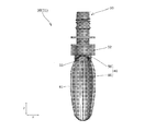
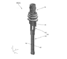
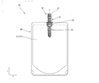
- Explanatory drawing which shows the pouch with a spout which concerns on 1st Embodiment of this invention.
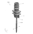
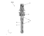
- Explanatory drawing which shows the spout which concerns on 1st Embodiment seen from the pouch front-back direction.
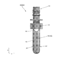
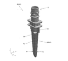
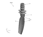
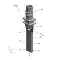
- Explanatory drawing which shows the spout which concerns on 1st Embodiment seen diagonally.
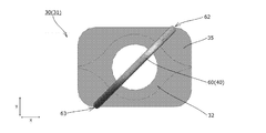
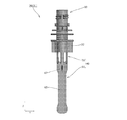
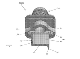
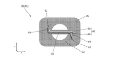
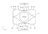
- Explanatory drawing which shows the spout which concerns on 1st Embodiment seen from a lower part.
- Explanatory drawing which shows roughly the state of each part at the time of the content pouring of 1st Embodiment.
- Explanatory drawing which shows the spout which concerns on 2nd Embodiment seen from the pouch front-back direction.
- Explanatory drawing which shows the spout which concerns on 2nd Embodiment seen diagonally. Explanatory drawing which shows the flow path formation part of the spout which concerns on 2nd Embodiment in sectional view. Explanatory drawing which shows the spout which concerns on 2nd Embodiment seeing from below. Explanatory drawing which shows the spout which concerns on 3rd Embodiment seen from the pouch front-back direction. Explanatory drawing which shows the spout which concerns on 3rd Embodiment seen diagonally. Explanatory drawing which shows the flow path formation part of the spout which concerns on 3rd Embodiment in sectional view. Explanatory drawing which shows the spout which concerns on 3rd Embodiment seen from lower direction.
- FIG. 20 is an explanatory view showing the spout according to the fifth embodiment as viewed obliquely from an angle different from FIG. 19.
- Explanatory drawing which shows the spout which concerns on 5th Embodiment seeing from below.
- Explanatory drawing which shows the spout which concerns on 6th Embodiment seen from the pouch front-back direction.
- Explanatory drawing which shows the spout which concerns on 6th Embodiment seen diagonally.
- Explanatory drawing which shows the spout which concerns on 7th Embodiment seen from the pouch front-back direction Explanatory drawing which shows the spout which concerns on 7th Embodiment seen diagonally.
- Explanatory drawing which shows the flow path formation part of the spout which concerns on 7th Embodiment in sectional view. Explanatory drawing which shows the spout which concerns on 7th Embodiment seeing from below. Explanatory drawing which shows the spout which concerns on 8th Embodiment seen from the pouch front-back direction. Explanatory drawing which shows the spout which concerns on 8th Embodiment from the opposite side to FIG. 29 seeing from the front-back direction of a pouch. Explanatory drawing which shows the spout which concerns on 8th Embodiment seen diagonally. Explanatory drawing which shows the flow path formation part of the spout which concerns on 8th Embodiment in sectional view.
- Explanatory drawing which shows the spout which concerns on 8th Embodiment seeing from below.
- Explanatory drawing which shows the spout which concerns on 9th Embodiment seen from the pouch front-back direction.
- Explanatory drawing which shows the spout which concerns on 9th Embodiment seeing diagonally.
- Explanatory drawing which shows the flow path formation part of the spout which concerns on 9th Embodiment in sectional view.
- Explanatory drawing which shows the spout which concerns on 9th Embodiment seeing from below.
- Explanatory drawing which shows the pouch with a spout which concerns on 10th Embodiment of this invention.
- Explanatory drawing which shows the spout main body as seen from the front and back sides of the pouch.
- Explanatory drawing which shows the dimensional relationship of a 1st flange part and a mounting part seen from an upper part.
- Explanatory drawing which shows the dimensional relationship of a 2nd flange part and a mounting part seen from an upper part.
- Explanatory drawing which shows the modification of a 1st flange part or a 2nd flange part.
- Explanatory drawing which shows the modification of a 2nd flange part.
- the spout-equipped pouch 10 is configured by attaching a spout 30 functioning as a spout to a pouch 20 formed in a bag shape by heat-sealing stacked films at a predetermined location, and forming a jelly. It contains a viscous content such as a beverage or a fluid content such as a liquid or a sherbet (content liquid).
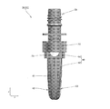
- the spout 30 is made of a synthetic resin or the like, and as shown in FIG. 1, has a spout body 31 attached to the pouch 20, and a cap portion 37 detachably attached to the spout body 31.
- the spout body 31 has a boat-shaped cross section (specifically, the spout body 31 protrudes outward from the both ends of the pouch left-right direction X in the cylindrical portion toward the outside of the pouch left-right direction X). (A shape in which a substantially triangular protrusion is formed) or a rhombus-shaped mounting portion 32, a spout cylinder portion 33 extending upward from the mounting portion 32, and a space above each other above the mounting portion 32. It integrally has a plurality of formed flange portions 35 and 36, and an extending portion 40 that extends downward from the attachment portion 32 and that is disposed inside the pouch 20 (content storage portion 23).
- the mounting portion 32 is disposed between the front side film portion 21 and the back side film portion 22 of the pouch 20 in a state in which the longitudinal direction thereof is oriented in the pouch left-right direction X, and heat attachment or It is a portion that is fixed to the front film portion 21 and the back film portion 22 by adhesion or the like.
- the mounting portion 32 has a round hole-shaped pouring hole 32a formed along the vertical direction Z.
- the spouting tube portion 33 is a cylindrical portion having a spouting hole 32a of the mounting portion 32 and a round hole-shaped spouting hole 33a continuous in the up-down direction Z.
- a screw capable of engaging with the cap portion 37 is provided on the upper end side (above the second upper flange portion 36) of the spout tube portion 33.
- the portion 33b is formed on the upper end side (above the second upper flange portion 36) of the spout tube portion 33.
- the plurality of flange portions 35, 36 have a first flange portion 35 formed at the bottom (formed closest to the mounting portion 32) and an upper portion of the first flange portion 35.
- a plurality of (two in the present embodiment) second flange portions 36 that are formed are included.
- the extension portion 40 is a portion for forming a flow path for contents inside the pouch 20 (contents storage portion 23), and as shown in FIGS. 1 to 4, below the attachment portion 32.
- the upper base portion 50 is continuously formed, and the flow path forming portion 60 is continuously formed below the upper base portion 50.
- the upper side base portion 50 is formed in a flat plate shape (or a substantially flat plate shape) and is integrally formed on the lower surface of the mounting portion 32 in a state parallel to the pouch left-right direction X and the vertical direction Z. There is. As shown in FIGS. 1 to 4, the upper side base portion 50 is formed with a through hole 51 penetratingly formed in the thickness direction thereof (pouch front-back direction Y) and communicating with the pouring hole 32a of the mounting portion 32. There is.
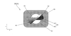
- the flow path forming portion 60 is composed of a twist portion (curving portion) 61 having a shape in which a plate-shaped member is curved so as to be twisted.
- the twist portion 61 has a substantially rectangular shape and a flat plate shape (or a substantially flat plate shape) in which R portions for reducing damage due to contact with the bag are formed at both corners on the lower end side thereof.
- a predetermined angle 45 ° in the present embodiment
- the plate-like members are evenly twisted so that they form a predetermined angle (45 ° in the present embodiment).
- the upper end portion of the twist portion 61 is integrally formed with the lower end surface of the upper base portion 50 with its longitudinal direction oriented in the pouch left-right direction X. Further, as shown in FIGS. 2 to 4, the lower end portion of the twist portion 61 has a longitudinal direction at a predetermined angle (45 ° in this embodiment) with respect to the pouch left-right direction X (and the pouch front-back direction Y). Is formed to make.
- the flow path forming portion 60 includes one front side vertical wrinkle forming portion 62 for forming a vertical wrinkle on the front side film portion 21 when the remaining amount of the content is reduced. It has one back side vertical wrinkle forming part 63 for forming a vertical wrinkle on the back side film part 22 when the remaining amount of the content is reduced.
- the front side vertical wrinkle forming portion 62 has a direction in which the extending portion 40 extends (that is, the front side and at least the downstream side of the flow path forming portion 60 facing the front side film portion 21 of the pouch 20). It is a portion formed so as to extend in the vertical direction Z (parallel or substantially parallel).
- the front-side vertical wrinkle forming part 62 faces the front-side film part 21 of the pouch 20 in each cross section of the flow-path forming part 60 (twist part 61) viewed in a cross section perpendicular to the vertical direction Z.
- the height of the pouch in the front-back direction Y is the highest, that is, it is located closest to the front film portion 21 side.
- the back side vertical wrinkle forming portion 63 is arranged on the back side of the flow path forming portion 60 facing the back side film portion 22 of the pouch 20 and at least on the downstream side in the direction in which the extending portion 40 extends (that is, It is a portion formed so as to extend in the vertical direction Z (parallel or substantially parallel).
- the back side vertical wrinkle formation part 63 faces the back side film part 22 of the pouch 20 in each cross section of the flow path formation part 60 (twist part 61) viewed in a cross section perpendicular to the vertical direction Z.
- the height of the pouch in the front-back direction Y is the highest on the back side, that is, it is located closest to the back film portion 22 side.
- the front side vertical wrinkle forming portion 62 and the back side vertical wrinkle forming portion 63 are formed at positions displaced from each other in the lateral direction X of the pouch, as shown in FIGS. 2 to 4.
- the left and right side edges (at least the lower side portions thereof) of the plate-shaped member forming the twist portion 61 (flow passage forming portion 60) are the front side vertical wrinkle forming portion 62.
- it functions as the back side vertical wrinkle forming portion 63.
- the left and right edges (vertical wrinkle forming portions 62, 63) of the plate-shaped member that constitutes the twist portion 61, as viewed in the pouch left-right direction X, are located on the front and back sides of the pouch as they move downward.
- the height in the direction Y is increased.
- the front side vertical wrinkle forming portion 62 and the back side vertical wrinkle forming portion 63 in the pouch front-back direction Y are formed.
- the distance D between the front side vertical wrinkle forming portion 62 and the back side vertical wrinkle forming portion 63 in the pouch front and back direction Y at the farthest position is equal to the pouch left and right (at the position where each vertical wrinkle forming portion 62, 63 is arranged). It is preferably set to 5 to 30% of the inner width dimension W of the content storage portion 23 of the pouch 20 in the direction X.
- the distance D in FIG. 4 indicates the distance D at the lower end of each vertical wrinkle forming portion 62, 63.
- the dimension of each vertical wrinkle forming portion 62, 63 in the extending direction of the extending portion 40 is preferably set to 20 to 60 mm.
- the extension 40 has a virtual line whose shape when viewed from below (projected in the vertical direction Z) is parallel to the pouch left-right direction X.
- a virtual line that is asymmetrical to the pouch front-back direction Y and is parallel to the pouch front-back direction Y (a virtual line that passes through the extended part 40) is used as a reference when (a virtual line passing through the extension 40) is used as a reference.
- the pouch is formed asymmetrically in the left-right direction X. Further, as shown in FIG.
- the extending portion 40 is also asymmetric in the front-back direction Y of the pouch and asymmetric in the left-right direction X of the pouch with respect to the shape of the lower end portion as viewed from the lower side.
- the lower end portion of the extending portion 40 in the present specification means a portion in the vicinity of the lowermost end portion including the lowermost end portion of the extending portion 40, and specifically, the extending portion in the vertical direction Z. It means the lower 10% of the entire length of the portion 40.
- the vertical dimension of the extending portion 40 is set to be 2 ⁇ 3 or less of the vertical dimension of the content storage portion 23 of the pouch 20, that is, the spout 30 in the horizontal direction X of the pouch is attached.
- the position in the example shown in FIG. 1, the center position in the left-right direction X of the pouch, it is set to 2/3 or less of the vertical dimension of the content-accommodating portion 23 of the pouch 20.
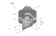
- each film portion 21 and 22 of the pouch 20 came into contact with the extended portion 40 as shown in FIG. It becomes a state.
- the flow path forming portion 60 is composed of the twisted portion 61 in which the plate-like member is curved so as to be twisted, as shown in FIG. Even when the film portions 21 and 22 come into contact with the extending portion 40, the gap G can be secured around the flow path forming portion 60. Thereby, the content can be satisfactorily poured out by using the gap G as a flow path.
- the extension portion 40 has the front side vertical wrinkle forming portion 62 and the back side vertical wrinkle forming portion 63, as shown in FIG. Since vertical wrinkles can be formed in the film portions 21 and 22 even in the lower region, the gap G generated between the front film portion 21 and the back film portion 22 due to the formation of the vertical wrinkles is contained. It can be used as a flow path for product discharge.
- the front side vertical wrinkle forming portion 62 and the back side vertical wrinkle forming portion 63 of the extension portion 40 are formed at positions displaced from each other in the pouch left-right direction X, as shown in FIG. It is possible to shift the position of the vertical wrinkles formed on 21 and the position of the vertical wrinkles formed on the back film portion 22 in the horizontal direction X of the pouch. Suppress or delay the phenomenon that the left and right film contact regions where the front side film part 21 and the back side film part 22 are in contact with each other, which expands from both outsides to the inside, are connected or almost connected in the vicinity of the center of the pouch left-right direction X. be able to.
- the flow path forming section 60 is composed of the twisted section 61 which is formed by bending the plate-shaped member to be twisted. Therefore, as the remaining amount of the content is reduced, the film portions 21 and 22 can be brought into close contact or almost close contact with the outer surface of the twisted portion (curved portion) 61 to eliminate or narrow the gap G. , The amount of contents remaining in the gap G can be reduced.
- the front side film portion 21 and the back side film portion 22 can be brought into close contact with each other in a region below the extending portion 40, so that the portion below the extending portion 40 It is possible to reduce the amount of the contents remaining in the area.
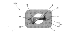
- the second embodiment is exactly the same as the above-described first embodiment except for a part of the configuration, and therefore the description of the configuration other than the difference is omitted.
- the plate-shaped member is formed on the rear side in the twisting direction of the plate-shaped member.
- a lip portion 64 that rises in the front and back direction of the member is formed.
- the twist portion 61 has the lip portions 64 that rise in the front and back directions of the plate-shaped member on both left and right edges of the plate-shaped member, the rigidity of the twist portion 61 can be improved and It is possible to prevent the installation portion 40 from being damaged.
- a method of forming the twist portion 61 it is conceivable to form the twist portion 61 by bending (twisting) a plate-shaped member, but in such a case, the lip portion 64 is formed into a plate shape. It is also possible to use it as a part for catching a tool when bending (twisting) a member.
- FIGS. 10 to 13 a pouch 10 with a spout according to a third embodiment of the present invention will be described based on FIGS. 10 to 13.
- the third embodiment is exactly the same as the above-described first embodiment except for a part of the configuration, and therefore the description of the configuration other than the difference is omitted.
- the twist portion 61 (flow passage forming portion 60) has a shape in which a flat plate-shaped member is twisted around the vertical axis by a predetermined angle (45 °).
- the twist portion 61 is a curved plate-shaped plate member that is curved so as to undulate in the left-right direction of the plate-shaped member. It has a shape twisted around a predetermined angle (45 °).
- FIGS. 14 to 17 a pouch 10 with a spout according to a fourth embodiment of the present invention will be described based on FIGS. 14 to 17.
- the fourth embodiment is exactly the same as the above-described third embodiment except for a part of the configuration, and therefore the description of the configuration other than the difference is omitted.
- plate-shaped members are formed on the left and right edges of the plate-shaped member that constitutes the twist part 61 (flow path forming part 60) on the rear side in the twisting direction of the plate-shaped member.
- a lip portion 64 that rises in the front and back direction of the member is formed.
- FIGS. 18 to 21 a pouch 10 with a spout according to a fifth embodiment of the present invention will be described based on FIGS. 18 to 21.
- the fifth embodiment is exactly the same as the above-described first embodiment except for a part of the configuration, and therefore the description of the configuration other than the difference is omitted.
- the extension portion 40 forms an angle of a predetermined angle (45 ° in the present embodiment) with respect to the pouch left-right direction X and the pouch front-back direction Y.
- the flow path forming portion 60 is formed in a flat plate shape (or a substantially flat plate shape) and is continuously formed below the mounting portion 32.
- a through hole 68 is formed in the upper portion of the flow path forming portion 60 so as to penetrate along the thickness direction thereof and communicate with the pouring hole 32a of the mounting portion 32. .
- the extending portion 40 is formed such that the entire shape of the extending portion 40 when viewed from below is asymmetrical in the pouch front-back direction Y and asymmetric in the pouch left-right direction X. . Further, as shown in FIG. 21, the extending portion 40 is also asymmetric in the front-back direction Y of the pouch and in the left-right direction X of the pouch with respect to the shape of the lower end portion as viewed from the lower side.
- the left and right side edges (at least the lower side portions thereof) of the flat plate-like flow path forming portion 60 are the front side vertical wrinkle forming portion 62 or the back side vertical wrinkle forming portion. Function as 63.
- a pouch 10 with a spout according to a sixth embodiment of the present invention will be described with reference to FIGS.
- the sixth embodiment is exactly the same as the above-described first embodiment except for a part of the configuration, and therefore the description of the configuration other than the difference is omitted.
- the extending portion 40 is a substantially rectangular and flat plate-like member having R portions formed at both corners on the lower end side thereof, and is provided around the vertical axis.
- the twisted portion 61 (flow passage forming portion 60) is twisted at an angle (20 ° in the present embodiment).
- the upper end portion of the twist portion 61 is attached to the lower end surface of the mounting portion 32 so that the longitudinal direction thereof forms an angle (about 11 ° in the present embodiment) with the pouch left-right direction X. It is formed integrally. 22 to 24, the lower end portion of the twist portion 61 is formed such that its longitudinal direction forms an angle (about 9 ° in the present embodiment) with respect to the pouch left-right direction X.
- a through hole 68 is formed in the upper portion of the twist portion 61 (flow passage forming portion 60) so as to penetrate in the thickness direction thereof and communicates with the pouring hole 32a of the mounting portion 32. Are formed.
- the extending portion 40 has a shape in which the lower end of the extending portion 40 is asymmetrical in the front / back direction Y of the pouch and asymmetric in the left / right direction X of the pouch. There is.
- the left and right side edges (at least the lower side portions thereof) of the flow path forming portion 60 function as the front side vertical wrinkle forming portion 62 or the back side vertical wrinkle forming portion 63. To do.
- a pouch 10 with a spout according to a seventh embodiment of the present invention will be described based on FIGS. 25 to 28.
- the seventh embodiment is exactly the same as the above-described first embodiment except for a part of the configuration, and therefore the description of the configuration other than the difference is omitted.
- the flow path forming portion 60 is composed of a curved portion 61 in which a plate-shaped member is curved in a substantially C shape when viewed in the vertical direction Z. ing.
- the C-shaped curved portion 61 is arranged so as to open in one of the front and back directions Y of the pouch.
- a through hole 51 is formed in the upper base portion 50 so as to penetrate therethrough along the vertical direction Z and communicates with the pouring hole 32a of the mounting portion 32. ing.
- the extension portion 40 is formed such that the shape of the extension portion 40 as viewed from the lower side is asymmetrical in the pouch front-back direction Y. Further, as shown in FIG. 28, the extending portion 40 is also formed asymmetrically in the front-back direction Y of the pouch with respect to the shape of the lower end portion as viewed from the lower side.
- the pouch with spout 10 according to the eighth embodiment of the present invention will be described with reference to FIGS. 29 to 33.
- the eighth embodiment is exactly the same as the above-described first embodiment except for a part of the configuration, and therefore the description of the configuration other than the difference is omitted.
- the flow path forming portion 60 includes a flat plate-shaped base portion 65 disposed in parallel with the pouch left-right direction X and the vertical direction Z, and the pouch front and back sides of the base portion 65. It has a first protruding piece 66 protruding from one surface in the direction Y and a second protruding piece 67 protruding from the other surface in the pouch front-back direction Y of the base portion 65.
- the first projecting piece 66 is formed over the entire area of the base part 65 in the vertical direction Z at the center of the pouch left-right direction X of the base portion 65, and the second projecting piece 67 is formed in the pouch left-right direction of the base part 65. It is formed only on the upper side portion of the base portion 65 at the center of X.
- the first projecting piece 66 and the second projecting piece 67 are formed parallel to the front-back direction P and the vertical direction Z of the pouch.
- the upper base 50 includes a plurality of (four) pieces extending in the up-down direction Z so as to connect the attachment portion 32 and the flow path forming portion 60. It is composed of connecting pieces.
- the extending portion 40 has a shape in which the lower end portion when viewed from the lower side is formed asymmetrically in the front-back direction Y of the pouch.
- FIGS. 34 to 37 a pouch 10 with a spout according to a ninth embodiment of the present invention will be described with reference to FIGS. 34 to 37.
- the ninth embodiment is exactly the same as the above-described first embodiment except for a part of the configuration, and therefore the description of the configuration other than the difference is omitted.
- the flow path forming portion 60 is a flat plate integrally formed on the lower end surface of the upper side base portion 50 in a state where the longitudinal direction thereof is directed in the pouch left-right direction X.
- the base portion 65 has a shape (or a substantially flat plate shape), and the left and right edges of the base portion 65 have lip portions 64 that stand up in the front-back direction of the base portion 65.
- the base portion 65 is formed parallel to the horizontal direction X and the vertical direction Z of the pouch, and one of the lip portions 64 projects toward one side of the front and back direction of the base portion 65, and the other of the lip portions 64 is a base. It is formed so as to project toward the other side of the front and back direction of the portion 65.
- the left and right lip portions 64 (at least the lower side portions thereof) of the flow path forming portion 60 function as the front side vertical wrinkle forming portion 62 or the back side vertical wrinkle forming portion 63. To do.
- the extension portion 40 is formed such that the shape of the extension portion 40 as viewed from the lower side is asymmetrical in the pouch front-back direction Y and asymmetric in the pouch left-right direction X. . Further, as shown in FIG. 37, the extending portion 40 is also asymmetrical in the pouch front-back direction Y and asymmetric in the pouch left-right direction X, even when viewed from the lower side of the lower end portion thereof.
- the pouch with spout 10 according to the tenth embodiment of the present invention will be described below with reference to the drawings.
- the spout-equipped pouch 10 is configured by attaching a spout 30 functioning as a spout to a pouch 20 formed in a bag shape by heat-sealing stacked films at a predetermined location, and forming a jelly. It contains a viscous and fluid content (content liquid) such as a beverage.
- the spout 30 is made of a synthetic resin or the like, and has a spout body 31 attached to the pouch 20 and a cap portion 37 detachably attached to the spout body 31 by screw engagement, as shown in FIG. There is.
- the spout body 31 has a boat-shaped cross-section (specifically, a substantially cylindrical portion that protrudes outward from the vicinities of both ends of the pouch left-right direction X toward the outside in the left-right direction X of the pouch).
- a mounting part 32 formed in a shape in which a triangular protrusion is formed), a spouting cylinder part 33 extending upward from the mounting part 32, and a downward extending from the mounting part 32 to the inside of the pouch 20.
- the extended portion 40 arranged is integrally provided with a plurality of flange portions 35 and 36 which are formed above the mounting portion 32 and are spaced apart from each other.
- the mounting portion 32 is disposed between the front side film portion 21 and the back side film portion 22 of the pouch 20 with its longitudinal direction facing the pouch left-right direction X, and is attached by heat welding or the like. It is a portion fixed to the front film portion 21 and the back film portion 22.
- the mounting portion 32 has a front-side mounting portion end surface 32b facing the front side in the pouch front-back direction Y and a back-side mounting portion end surface 32c facing the back side in the pouch front-back direction Y.
- the mounting portion 32 has a round hole-shaped pouring hole 32a formed along the vertical direction Z.
- the spout tube portion 33 is a cylindrical portion having a spout hole 32a of the mounting portion 32 and a round spout hole 33a continuous in the vertical direction Z.
- a screw portion 33b engageable with the cap portion 37 is provided at the upper end side (above the second flange portion 36) of the dispensing cylinder portion 33, on the outer peripheral surface of the dispensing cylinder portion 33.
- an inter-flange portion 33c is formed on the outer peripheral surface of the pouring cylinder portion 33, as shown in FIG.
- the inter-flange portion 33c faces the front or back side of the pouch front and back direction Y, faces the front and back end faces parallel to the pouch left and right direction X and the up and down direction Z, and faces the left and right sides of the pouch left and right direction X. It has a left end face and a right end face that are parallel to the direction Y and the vertical direction Z.
- the front end surface and the back end surface of the inter-flange portion 33c are formed so as not to protrude outward in the pouch front-back direction Y beyond the flange portions 35, 36 over the entire surface thereof.
- the front end surface and the back end surface of the inter-flange portion 33c are located in the pouch front-back direction more than the flange portions 35, 36 at the central position C corresponding to the central axis of the pouring hole 32a in the pouch left-right direction X. It is located inside Y.
- the left end surface and the right end surface of the inter-flange portion 33c are located inside the pouch left-right direction X with respect to the flange portions 35 and 36.
- the extension portion 40 is a portion that is disposed inside the pouch 20 and forms a flow path for pouring the contents into the pouch 20.
- the plurality of flange portions 35, 36 have a first flange portion 35 formed at the bottom (formed closest to the mounting portion 32) and an upper portion of the first flange portion 35.
- the formed second flange portion 36 is included.
- the first flange portion 35 is formed above the mounting portion 32 so as to be adjacent to each other without a gap, and as shown in FIGS. 39 and 40, the first front side flange end surface 35a facing the front side in the pouch front and back direction Y and the pouch front and back sides. It has the 1st back side flange end surface 35b which faces the back side in the direction Y.
- each of the flange end surfaces 35a, 35b of the first flange portion 35 is on the front side in the rotational direction of the spout body 31 relative to the cap portion 37 when the cap is opened (a torque is applied when the cap is opened).
- Side a first flange bulging portion 35c, a flat portion 35e formed on the rear side in the rotational direction, and R portions formed on both ends of the flange end surfaces 35a and 35b in the pouch left-right direction X. is doing.
- the first flange bulging portion 35c is formed by bulging outward in the front-back direction Y of the pouch at a position closer to the front side in the rotational direction than the central position C, and specifically, The convex portion is formed as a convex portion protruding outward in the front-back direction Y of the pouch from the flat portion 35e.
- Each first flange bulge 35c has a flat portion 35d formed in parallel with the pouch left-right direction X and the vertical direction Z.
- the flat portion 35e is formed so as to straddle the center position C, and is formed in parallel with the pouch horizontal direction X and the vertical direction Z.
- the flange end surfaces 35a, 35b are located outside the mounting portion end surfaces 32a, 32b in the front-back direction Y of the pouch.
- the second flange portion 36 is formed on the outer periphery of the spout tube portion 33 above the first flange portion 35 and below the screw portion 33b.
- the second flange portion 36 has a second front side flange end surface 36a facing the front side in the pouch front and back direction Y and a second back side flange end surface 36b facing the back side in the pouch front and back direction Y. ing.
- each of the flange end surfaces 36a, 36b of the second flange portion 36 bulges outward in the front-back direction Y of the pouch at a position closer to the front side and the rear side in the rotational direction than the central position C.
- the second flange bulging portions 36c are respectively provided.
- R portions are formed at both ends of the flange end surfaces 35a and 35b in the left-right direction X of the pouch.
- each of the second flange bulging portions 36c has a concave curved surface 36d formed on the central position C side and a flat portion 36e formed outside the curved surface 36d in the left-right direction P of the pouch. And have.
- the curved surface 36d on the front side and the curved surface 36d on the rear side in the rotation direction are smoothly and continuously formed as shown in FIG. 41, whereby the flange end surfaces 36a, 36b in the left-right direction X of the pouch.
- a concave curved portion 36f is formed in the center.
- each flat portion 36e is located outside the curved surface 36d in the front-back direction Y of the pouch, and is formed parallel to the left-right direction X and the vertical direction Z of the pouch.
- the flat portion 36e of the second flange portion 36 is closer to the pouch front-back direction Y than the outermost portion (the flat portion 35d in the present embodiment) of the first flange bulging portion 35c of the first flange portion 35 in the pouch front-back direction Y. It is located outside or in the same position as the outermost portion of the first flange bulging portion 35c in the front-back direction Y of the pouch.
- the cap portion 37 has a screw portion (not shown) engageable with the screw portion 33b of the spout body 31 on its inner peripheral surface, and rotates the cap portion 37 with respect to the spout body 31 about the vertical axis.
- the cap portion 37 is configured to be opened and closed. Specifically, in the present embodiment, when the cap portion 37 is viewed from above, when the cap portion 37 is rotated clockwise, the cap portion 37 is closed and the cap portion 37 is rotated counterclockwise.
- the cap portion 37 is configured to be opened when it is opened.
- the distance D1 in the pouch front-back direction Y between the front-side mounting portion end surface 32b (the outermost portion) and the first front-side flange end surface 35a (the outermost portion) at the central position C is , 0.5 mm or less.
- the distance D1 is preferably set to be equal to or greater than the thickness dimension T1 of the front film portion 21, and further, the distance D1 is set to 1.0 to 3.0 times the thickness dimension T1 of the front film portion 21.
- the distance D2 in the pouch front-back direction Y between the back side mounting portion end surface 32c (the outermost portion) and the first back flange end surface 35b (the outermost portion) at the central position C is , 0.5 mm or less.
- the distance D2 is preferably set to be equal to or larger than the thickness dimension T2 of the back side film portion 22, and further, the distance D2 is set to 1.0 to 3.0 times the thickness dimension T2 of the back side film portion 22.
- the distance D2 is set to 1.0 to 3.0 times the thickness dimension T2 of the back side film portion 22.
- the thickness dimension T1 and the thickness dimension T2 are set equal, and the distance D1 and the distance D2 are set equal.
- the distance D3 in the pouch front-back direction Y between the front-side mounting portion end surface 32b (the outermost portion) and the second front-side flange end surface 36a (the outermost portion) at the central position C is , 0.5 mm or less.
- the distance D4 in the pouch front-back direction Y between (the outermost portion of) the back side mounting portion end surface 32c and the second back side flange end surface 36b at the central position C is set within 0.5 mm. Has been done.
- the distance D5 in the pouch front-back direction Y between the front end surface (the outermost portion) of the inter-flange portion 33c and the first front flange end surface 35a (the outermost portion) at the central position C is 0.5 mm or less.
- the distance D6 in the front-back direction Y of the pouch between the front end surface (the outermost portion) of the inter-flange portion 33c and the second front flange end surface 36a (the outermost portion) at the center position C. Is set within 0.5 mm.
- the distance D7 in the pouch front-back direction Y between (the outermost portion of) the back side end surface of the inter-flange portion 33c and (the outermost portion) of the first back side flange end surface 35b at the central position C is within 0.5 mm.
- the distance D8 in the front-back direction Y of the pouch between the front end surface (the outermost portion) of the inter-flange portion 33c and the second back flange end surface 36b (the outermost portion) at the center position C. Is set within 0.5 mm.
- the pouch 10 with spout 10 may be configured by arbitrarily combining the configurations of the plurality of embodiments and modifications described above or below.
- the film forming the pouch 20 may be in any specific form, and specific examples thereof include synthetic resin films such as polyester, polypropylene, polyamide, polyethylene, polybutylene terephthalate, and ethylene-vinyl alcohol copolymer. Formed by laminating a known synthetic resin film such as a coating film or a vapor deposition film that imparts gas barrier property or moisture barrier property to these synthetic resin films, or laminating paper or aluminum foil on the synthetic resin film. And the like.
- the front film portion 21 and the back film portion 22 may be formed of separate films separated from each other, or may be formed as one continuous film.
- the entire flow path forming portion 60 has been described as including the curved portion (twist portion) 61, but the vertical direction of the flow path forming portion 60 is described.
- the twisted portion (curved portion) 61 may be formed only in a partial area of Z, and for example, the twisted portion (curved portion) 61 may be formed only in the area below the flow path forming portion 60.
- the twist portion 61 has been described as having a shape in which the plate member is twisted by 20 ° or 45 °, but the twist angle of the twist portion 61 is It is not limited to the above, and any one may be used.
- the twisting angle of the twisted portion 61 is set to 10 ° to 60 °, a gap G is formed around the twisted portion 61 even when the film portions 21 and 22 are in contact with the twisted portion 61 during the process of pouring out the contents.
- the twist portion 61 has been described as having a shape in which the plate member is twisted around the vertical axis (of the pouch 20 or the plate member).
- the central axis of the twist is not limited to the vertical axis, and for example, an axis inclined with respect to the vertical axis (of the pouch 20 or the plate member) may be the center of the twist.
- the lip portions 64 are formed on the left and right edges of the plate member or the base portion 65, but the left and right sides of the plate member or the base portion 65 are described.
- the lip portion 64 may be formed on only one of the edges.
- the lip portion 64 is formed over the entire left and right side edges of the plate-shaped member in the up-down direction Z, but the plate-shaped member or the base portion is described.
- the lip portions 64 may be formed only in a part of the left and right side edges of 65 in the up-down direction Z, for example, the lip portions 64 may be formed only in the area below the plate member or the base portion 65. .
- a portion of which the shape (cross-sectional shape) when viewed from the lower side is formed asymmetrically in the pouch front-back direction Y is located in at least a partial region of the extended portion 40 in the vertical direction Z. It only needs to be formed.
- at least a part of the extended portion 40 in the up-down direction Z is also a portion in which the shape (cross-sectional shape) when viewed from below is formed asymmetrically in the lateral direction X of the pouch. It only needs to be formed.
- the vertical dimension of the extension portion 40 is described as being set to be 2 ⁇ 3 or less of the vertical dimension of the content storage portion 23 of the pouch 20, but the extension portion 40 is described.
- the vertical dimension of the above is not limited to this, and for example, the vertical dimension of the extending portion 40 may be set to about 60 to 90% of the vertical dimension of the content storage portion 23 of the pouch 20.
- the extended portion 40 has been described as being integrally formed with the mounting portion 32, but the extended portion 40 and the mounting portion 32 are separately formed and mounted by fitting or the like. The extension portion 40 may be attached to the portion 32.
- the first flange portion 35 has been described as being formed adjacent to and above the attachment portion 32, but the first flange portion 35 is provided above the attachment portion 32 and the attachment portion 32. May be formed separately from.
- both the first front-side flange end surface 35a and the first back-side flange end surface 35b have been described as having the first flange bulging portion 35c, but the first front-side flange end surface 35a.
- the first flange bulging portion 35c may be formed on only one of the first back side flange end surfaces 35b.
- the central position of the mounting portion 32, the spouting cylinder portion 33, the inter-flange portion 33c, the first flange portion 35, and the second flange portion 36 in the pouch left-right direction X is the central position.
- at least one central position of the mounting portion 32, the spouting tubular portion 33, the inter-flange portion 33c, the first flange portion 35, and the second flange portion 36 is the central position. It may be displaced from C in the lateral direction X of the pouch.
- the central position of the mounting portion 32, the spouting tubular portion 33, the inter-flange portion 33c, the first flange portion 35, and the second flange portion 36 in the pouch front-back direction Y is the front and back of the pouch.
- the mounting portion 32, the pouring cylinder portion 33, the inter-flange portion 33c, the first flange portion 35, and the At least one central position of the two flange portions 36 may be displaced in the pouch front-back direction Y from the central position corresponding to the central axis of the pouring hole 32a in the pouch front-back direction Y.
- the flange end surfaces 35a, 35b, 36a, 36b are described as being located outside the mounting portion end surfaces 32a, 32b in the central position C in the front-back direction Y of the pouch.
- At least one of the flange end surfaces 35a, 35b, 36a, 36b is located inside the mounting portion end surfaces 32a, 32b in the pouch front-back direction Y at the central position C, or the mounting portion end surfaces 32a, 32b are the same in the pouch front-back direction Y. It may be located at a position.
- the distances D1 to D4 are set to have the same dimensions, but the dimension design of the distances D1 to D4 is not limited to the above, and at least one of the distances D1 to D4 is set.
- the dimensions of the distances D1 to D4 may be arbitrarily set, for example, one of them may have a different dimension.
- the dimension difference between the distance D1 and the distance D3 is within 0.25 mm, and the dimension of the distance D3 is larger than that of the distance D1. It is preferable to set a large value.
- the dimension setting of the distance D2 and the dimension setting of the distance D4 are made different, it is preferable that the dimension difference between the distance D2 and the distance D4 is within 0.25 mm, and the distance D4 is larger than the distance D4. It is preferable to set a large size.
- the first flange portion 35 has been described as being formed in the shape shown in FIG.
- the specific aspect of the first flange portion 35 is not limited to the above.
- a shape similar to the shape of the second flange portion 36 shown in FIG. 41 may be adopted, and as in the modification shown in FIG. A mode in which the portion 35c is not formed may be adopted.
- the first front side flange end surface 35a and the first back side flange end surface 35b are formed so as to straddle the central position C, and are flat portions parallel to the pouch horizontal direction X and the vertical direction Z. And R portions formed on both ends of the flat portion of the pouch in the left-right direction X.
- the distances D1 and D2 described above are set within 0.5 mm.
- the second flange portion 36 has been described as being formed in the shape shown in FIG. 41, but the specific aspect of the second flange portion 36 is not limited to the above, and for example, As the aspect of the second flange portion 36, the same shape as the shape of the first flange portion 35 shown in FIG. 40 may be adopted, and as in the modification shown in FIG. A mode in which 35c is not formed may be adopted. In the modification shown in FIG.
- the second front side flange end surface 36a and the second back side flange end surface 36b are formed so as to straddle the central position C, and are flat parts parallel to the pouch horizontal direction X and the vertical direction Z. And R portions formed on both ends of the flat portion of the pouch in the left-right direction X. Further, in the modification shown in FIG. 42, the distances D3 and D4 described above are set within 0.5 mm. Moreover, as the aspect of the second flange portion 36, the aspect as shown in FIG. 43 in which the above-mentioned distances D3 and D4 are set to be larger than 0.5 mm may be adopted.
- the second flange bulging portion 36 protruding outward in the front and back direction Y of the pouch can prevent the finger of the user who holds the mounting portion 32 or the first flange portion 35 from hitting the cap portion 37.
- a so-called band split type cap portion 37 in which a TE (tamper evidence) band remains on the side of the cap portion 37 it is possible to prevent the user's finger from hitting the TE band. Therefore, it is possible to stably open and close the cap.
- one second flange portion 36 has been described, but the number of the second flange portions 36 may be two or more. The flange portion 36 may not be formed.
- the spout-equipped pouch 10 can be conveyed through the rail between the first flange portion 35 and the second flange portion 36, so that the second flange portion 36 is It is preferably formed.
- knurling is performed on the attachment end surfaces 32a, 32b of the attachment portion 32 and the flange end surfaces 35a, 35b, 36a, 36b of the flange portions 35, 36, particularly the flange end surfaces 35a, 35b of the first flange portion 35.
- anti-slip processing such as blast processing may be applied.
- the front film portion 21 and the back film portion 22 may be formed of separate films separated from each other, or may be formed as one continuous film.
- Bay Curved surface 36e ⁇ ⁇ ⁇ Flat portion 36f ⁇ ⁇ ⁇ Concave curved portion 37 ⁇ ⁇ ⁇ Cap portion 40 ⁇ ⁇ ⁇ Extended portion 50 ⁇ ⁇ ⁇ Upper side base portion 51 ⁇ ⁇ ⁇ Through hole 60 ⁇ ⁇ ⁇ Flow path forming portion 61 ⁇ ..Twist part (curved part) 62 ... front side vertical wrinkle forming part 63 ... back side vertical wrinkle forming part 64 ... lip part 65 ... base part 66 ... first projecting piece 67 ... second projecting piece 68 ... Through hole C ⁇ ⁇ ⁇ Central position X ⁇ ⁇ ⁇ Pouch left and right direction Y ⁇ ⁇ ⁇ Pouch front and back direction Z ⁇ ⁇ ⁇ Vertical direction
Landscapes
- Engineering & Computer Science (AREA)
- Mechanical Engineering (AREA)
- Bag Frames (AREA)
Abstract
Provided is a spout that is of simple construction and convenient to use. This spout (30) is equipped with: an attachment part (32) to be mounted to a pouch (20); and an extension part (40) that extends downward from the attachment part (32) so as to form a content flow passage inside the pouch (20), wherein the extension part (40) has, at least in a region thereof in the vertical direction, a portion shaped so as to be asymmetrical in the obverse-reverse direction (Y) of the pouch when viewed from below, with reference to a virtual line parallel to the right-left direction (X) of the pouch.
Description
本発明は、パウチに装着されるスパウトおよびスパウト付きパウチに関する。
The present invention relates to a spout attached to a pouch and a pouch with a spout.
従来、ゼリー状飲料等の粘性および流動性を有した内容物を収容する容器として、重ねたフィルムを所定箇所で熱溶着することで袋状に形成したパウチを用いることが公知であり、また、このようなパウチの注出口に、注出孔を有したスパウトを装着することで、内容物を容易に注出することを可能にすることも公知である。
Conventionally, it is known to use a pouch formed into a bag shape by heat-sealing stacked films as a container for storing contents having viscosity and fluidity such as jelly-like beverages, It is also known that a spout having a spout hole can be attached to the spout of such a pouch to make it possible to easily spout the contents.
このようなスパウト付きパウチでは、内容物の残量低減時に、表側フィルム部と裏側フィルム部とが密着して、スパウトの注出孔の入口付近を塞がれ、内容物の注出が阻害されてしまうことがある。
In such a pouch with a spout, when the remaining amount of the content is reduced, the front film portion and the back film portion are in close contact with each other and the vicinity of the inlet of the spout pouring hole is blocked to prevent the pouring of the content. It may happen.
そこで、上述したような、スパウトの注出孔の入り口付近が塞がってしまう現象を回避するために、パウチに装着されるスパウトの取付部の下方に、取付部から下方に向けて延び、パウチの内側に配置されて内容物用の流路を形成するための延設部(閉塞防止部材)を設けることが知られている(例えば、特許文献1を参照)。
Therefore, in order to avoid the above-described phenomenon in which the vicinity of the entrance of the spout pouring hole is blocked, the spout attached to the pouch is extended below the attachment part of the spout, and the pouch of the pouch is extended downward. It is known to provide an extended portion (blocking prevention member) arranged inside to form a flow path for contents (see, for example, Patent Document 1).
しかしながら、このような延設部を設けた場合でも、図44に示すように、内容物の残量低減が進むに従ってパウチ左右方向の両外側から内側に向けて、表側フィルム部と裏側フィルム部とが密着したフィルム密着領域Rが拡大していき、このような左右のフィルム密着領域Rがパウチ左右方向の中央付近において繋がるまたはほぼ繋がってしまう現象が生じることがある。そして、このような左右のフィルム密着領域Rが繋がるまたはほぼ繋がってしまうと、繋がったフィルム密着領域Rの下方のパウチの底部124に残留した内容物を注出することが困難になる。
However, even when such an extended portion is provided, as shown in FIG. 44, as the remaining amount of the content is reduced, the pouch is moved from the outer side to the inner side in the left-right direction to the front film portion and the back film portion. There is a possibility that the film contact area R in which the film adheres to each other expands, and such left and right film contact areas R are connected or almost connected in the vicinity of the center of the pouch left-right direction. When the left and right film contact regions R are connected or almost connected, it becomes difficult to pour out the contents remaining on the bottom portion 124 of the pouch below the connected film contact regions R.
また、上述したような、繋がったフィルム密着領域Rの下方のパウチの底部124に残留した内容物を注出することが困難になるという現象を回避する1つの案として、延設部の上下方向寸法を長く設定することも考えられるが、この場合、パウチを正立させたときやパウチが落下した場合に、延設部の先端がパウチの底付近に接触し、底部を破袋し、又は延設部自身が折れてしまうことにもなる。また、延設部の材料コストや重量が増加してしまうという問題が生じる。
In addition, as one plan for avoiding the phenomenon that it becomes difficult to pour out the contents remaining on the bottom portion 124 of the pouch below the connected film adhesion region R as described above, as a plan, It may be possible to set the dimension long, but in this case, when the pouch is erected upright or when the pouch falls, the tip of the extension part comes into contact with the vicinity of the bottom of the pouch, and the bottom part is broken, or The extension part itself may break. Further, there arises a problem that the material cost and the weight of the extension portion increase.
また、上述した問題とは別の問題として、特許文献2に開示されるような、外周側に突出するフランジ部が形成されたスパウトにおいては、以下の問題がある。
Further, as a problem different from the above-mentioned problem, the spout having the flange portion protruding to the outer peripheral side as disclosed in Patent Document 2 has the following problems.
すなわち、このようなスパウト付きパウチでは、使用者がキャップ開閉の操作を行う時、使用者が、一方の手の指で取付部の上方に形成されたフランジ部を掴むとともに、他方の手の指でキャップを掴んだ状態で、キャップを回転させることがある。
That is, in such a pouch with a spout, when the user performs the operation of opening and closing the cap, the user grasps the flange portion formed above the attachment portion with the finger of one hand and the finger of the other hand. The cap may be rotated while holding the cap with.
ところが、上下方向におけるフランジ部の厚みは薄く形成されているのが一般的であるため、フランジ部を掴んだ指にフランジ部が食い込み、使用者に痛みや不快感を覚させてしまうことがあるといった問題があった。
However, since the thickness of the flange portion in the up-down direction is generally thin, the flange portion may bite into the finger holding the flange portion, causing the user to feel pain or discomfort. There was such a problem.
そこで、本発明は、これらの問題点を解決するものであり、簡素な構成で、便利なスパウトおよびスパウト付きパウチを提供することを目的とするものである。
Therefore, the present invention solves these problems, and an object thereof is to provide a convenient spout and a pouch with a spout with a simple structure.
本発明のスパウトは、パウチに装着される取付部と、前記取付部から下方に向けて延び、パウチの内側に内容物用の流路を形成するための延設部とを備えたスパウトであって、前記延設部は、パウチ左右方向に平行な仮想線を基準とした場合に、下方側から見た場合の形状がパウチ表裏方向に非対称に形成された部分を、その上下方向における少なくとも一部領域に有していることにより、前記課題を解決するものである。
本発明のスパウト付きパウチは、前記スパウトと、表側フィルム部および裏側フィルム部を有し前記取付部に装着されるパウチとを備えたことにより、前記課題を解決するものである。
本発明の他の態様のスパウトは、パウチに装着される取付部と、前記取付部の上方に形成される1つ以上のフランジ部と、前記取付部に形成され上下方向に沿って延びる注出孔とを備えたスパウトであって、前記1つ以上のフランジ部には、最も下方に形成される第1フランジ部が含まれ、前記取付部は、パウチ表裏方向における表側に面する表側取付部端面と、パウチ表裏方向における裏側に面する裏側取付部端面とを有し、前記第1フランジ部は、パウチ表裏方向における表側に面する第1表側フランジ端面と、パウチ表裏方向における裏側に面する第1裏側フランジ端面とを有し、前記第1表側フランジ端面は、パウチ左右方向において前記注出孔の中心軸に対応する中央位置において、前記表側取付部端面よりもパウチ表裏方向の外側に位置し、前記第1裏側フランジ端面は、前記中央位置において、前記裏側取付部端面よりもパウチ表裏方向の外側に位置し、前記中央位置における、前記表側取付部端面と前記第1表側フランジ端面との間のパウチ表裏方向の距離D1は、0.5mm以内に設定され、前記中央位置における、前記裏側取付部端面と前記第1裏側フランジ端面との間のパウチ表裏方向の距離D2は、0.5mm以内に設定されていることにより、前記課題を解決するものである。
また、本発明の他の態様のスパウトは、パウチに装着される取付部と、前記取付部の上方に形成される1つ以上のフランジ部と、前記取付部に形成され上下方向に沿って延びる注出孔とを備えたスパウトであって、前記1つ以上のフランジ部には、最も下方に形成される第1フランジ部が含まれ、前記取付部は、パウチ表裏方向における表側に面する表側取付部端面と、パウチ表裏方向における裏側に面する裏側取付部端面とを有し、前記第1フランジ部は、パウチ表裏方向における表側に面する第1表側フランジ端面と、パウチ表裏方向における裏側に面する第1裏側フランジ端面とを有し、前記第1表側フランジ端面は、パウチ左右方向において前記注出孔の中心軸に対応する中央位置において、前記表側取付部端面よりもパウチ表裏方向の内側、または、前記表側取付部端面とパウチ表裏方向の同じ位置に位置し、前記第1裏側フランジ端面は、前記中央位置において、前記裏側取付部端面よりもパウチ表裏方向の内側、または、前記裏側取付部端面とパウチ表裏方向の同じ位置に位置していることにより、前記課題を解決するものである。
また、本発明の他の態様のスパウト付きパウチは、前記スパウトと、表側フィルム部および裏側フィルム部を有し前記取付部に装着されるパウチとを備えたスパウト付きパウチであって、前記距離D1は、前記表側フィルム部の厚み寸法T1以上に設定され、前記距離D2は、前記裏側フィルム部の厚み寸法T2以上に設定されていることにより、前記課題を解決するものである。 The spout of the present invention is a spout that includes an attachment portion that is attached to the pouch, and an extension portion that extends downward from the attachment portion and that forms a flow path for contents inside the pouch. The extending portion has a portion in which the shape when viewed from the lower side is asymmetrical in the front-back direction of the pouch when an imaginary line parallel to the left-right direction of the pouch is used as a reference. By having it in a partial area, the above problem is solved.
The pouch with a spout of the present invention solves the above problem by including the spout and a pouch that has a front film portion and a back film portion and is attached to the attachment portion.
A spout according to another aspect of the present invention is a spout attached to a pouch, one or more flanges formed above the attachment, and a spout formed on the attachment and extending in a vertical direction. A spout having a hole, wherein the one or more flange portions include a first flange portion formed at a lowermost position, and the mounting portion is a front mounting portion facing a front side in a front-back direction of the pouch. It has an end surface and a back side mounting portion end surface facing the back side in the front and back direction of the pouch, and the first flange portion faces a first front side flange end surface facing the front side in the front and back direction of the pouch and a back side in the front and back direction of the pouch. A first back side flange end surface, and the first front side flange end surface is outside the front and back sides of the pouch more than the front side mounting portion end surface at a central position corresponding to the center axis of the pouring hole in the left and right direction of the pouch. And the first back side flange end surface is located outside the back side mounting portion end surface in the pouch front and back direction at the central position, and the front side mounting portion end surface and the first front side flange end surface at the central position. The distance D1 in the front and back direction of the pouch is set within 0.5 mm, and the distance D2 in the front and back direction of the pouch between the end surface of the back mounting portion and the end surface of the first back flange at the central position is 0. The problem is solved by setting the thickness within 0.5 mm.
In addition, a spout according to another aspect of the present invention is a mounting portion mounted on a pouch, one or more flange portions formed above the mounting portion, and a vertical portion formed on the mounting portion. A spout having a pouring hole, wherein the one or more flange portions include a first flange portion formed at a lowermost portion, and the attachment portion is a front side facing a front side in a front-back direction of the pouch. It has a mounting portion end surface and a back side mounting portion end surface facing the back side in the front and back direction of the pouch, and the first flange portion has a first front side flange end surface facing the front side in the front and back direction of the pouch and a back side in the front and back direction of the pouch. And a first back-side flange end surface that faces the pouch front-back surface rather than the front-side mounting portion end surface at a central position corresponding to the central axis of the pouring hole in the pouch left-right direction. Of the front side mounting portion end surface and the pouch front and back direction at the same position, the first back side flange end surface at the central position, the back side mounting portion end surface inside the pouch front and back direction, or the The problem is solved by being located at the same position in the front and back direction of the pouch as the end surface of the back side mounting portion.
A pouch with a spout according to another aspect of the present invention is a pouch with a spout that includes the spout and a pouch that has a front film portion and a back film portion and is attached to the attachment portion, and the distance D1. Is set to be equal to or larger than the thickness dimension T1 of the front side film portion, and the distance D2 is set to be equal to or larger than the thickness dimension T2 of the back side film portion, thereby solving the above problem.
本請求項1に係る発明によれば、延設部が、パウチ左右方向に平行な仮想線を基準とした場合に、下方側から見た場合の形状がパウチ表裏方向に非対称に形成された部分を、その上下方向における少なくとも一部領域に有していることにより、内容物の残量低減時における延設部との接触に起因したシワ等の各フィルム部の変形状態を、表側フィルム部と裏側フィルム部とで異ならせることができる。これにより、内容物の残量低減が進むに従ってパウチ左右方向の両外側から内側に向けて拡大する、表側フィルム部と裏側フィルム部とが密着した左右のフィルム密着領域が、パウチ左右方向の中央付近において繋がるまたはほぼ繋がってしまう現象を抑制または遅らせることが可能であるため、当該フィルム密着領域の下方のパウチの底部に内容物が封入されてしまうことを抑制し、内容物を良好に注出することができる。
According to the invention of claim 1, when the extending portion is based on an imaginary line parallel to the left and right direction of the pouch, the shape when viewed from below is asymmetrical in the front and back direction of the pouch. By having at least a partial region in the vertical direction, the deformed state of each film portion such as wrinkles due to contact with the extended portion at the time of reducing the remaining amount of the content, and the front film portion. It can be different from the back film part. As a result, the left and right film contact regions where the front film portion and the back film portion are in contact with each other are expanded in the vicinity of the center of the pouch in the left-right direction. Since it is possible to suppress or delay the phenomenon of being connected or almost connected with each other, it is possible to prevent the contents from being enclosed in the bottom portion of the pouch below the film adhesion region and to pour out the contents well. be able to.
本請求項2に係る発明によれば、延設部が、パウチ表裏方向に平行な仮想線を基準とした場合に、下方側から見た場合の形状がパウチ左右方向に非対称に形成された部分を、その上下方向における少なくとも一部領域に有していることにより、内容物の残量低減時における延設部との接触に起因した各フィルム部の変形状態を、表側フィルム部と裏側フィルム部とでパウチ左右方向に異ならせることができる。これにより、特に、延設部との接触に起因して表側フィルム部に形成される縦ジワの位置と裏側フィルム部に形成される縦ジワの位置とをパウチ左右方向にずらすことが可能であるため、上述したフィルム密着領域がパウチ左右方向の中央付近で繋がるまたはほぼ繋がってしまう現象を抑制できる。
本請求項4に係る発明によれば、延設部の下端部の下方側から見た場合の形状が、パウチ表裏方向およびパウチ左右方向に非対称に形成されていることにより、上述した、内容物の残量低減時における延設部との接触に起因した各フィルム部の変形状態を、延設部よりも下方の領域においても得やすくなるため、延設部の下方の領域においても、上述した左右のフィルム密着領域がパウチ左右方向の中央付近で繋がるまたはほぼ繋がってしまう現象を抑制できる。また、延設部の下方の領域における各フィルム部の変形状態を制御することが可能であるため、延設部の上下方向の寸法を短く設計することが可能になるため、内容物注出の最終段階において、延設部よりも下方の領域において表側フィルム部と裏側フィルム部とが密着することを延設部が阻害することがないため、延設部よりも下方の領域に残留する内容物の量を低減することができる。また、パウチを正立させたときやパウチが落下したときでも、延設部の先端がパウチの底部に接触することを抑制し、底付近を破袋し、又は延設部自身が折れてしまうことを防げる。また、スパウトの材料コストや重量を低減することも可能となる。
本請求項5に係る発明によれば、延設部が、延設部のパウチの表側フィルム部に面する側かつ少なくとも下流側において、延設部が延びる方向に延びた表側縦ジワ形成部と、延設部のパウチの裏側フィルム部に面する側かつ少なくとも下流側において、延設部が延びる方向に延びた裏側縦ジワ形成部とを有し、延設部の表側縦ジワ形成部と裏側縦ジワ形成部とが互いにパウチ左右方向にずれた位置に形成されている。これにより、延設部よりも下方の領域においても、各フィルム部に縦ジワを形成し、縦ジワの形成に起因して生じる表側フィルム部および裏側フィルム部の間隙を内容物注出用の流路として利用することができるばかりでなく、表側フィルム部に形成される縦ジワの位置と裏側フィルム部に形成される縦ジワの位置とをパウチ左右方向にずらすことが可能であるため、上述したフィルム密着領域がパウチ左右方向の中央付近で繋がるまたはほぼ繋がってしまう現象を抑制できる。
本請求項7に係る発明によれば、延設部が、板状部材を湾曲させた形状の湾曲部を有していることにより、内容物注出の途中段階においては、内容物の残量低減の進行に伴って各フィルム部が延設部に接触した時にも、延設部の周囲に間隙を確保し、当該間隙を流路として利用して内容物を良好に注出することができ、また、内容物注出の最終段階においては、内容物の残量低減の進行に伴って各フィルム部を湾曲部の外面に密着させまたはほぼ密着させ、前記間隙を無くすまたは狭くすることが可能であるため、前記間隙に残留する内容物の量を低減することができる。また、内容物を注出させる時には、使用者の指によってパウチを外側から押すことで、延設部と各フィルム部との間に残留した内容物を絞り出すことがあるが、本請求項7に係る発明では、使用者の指を湾曲部にフィットさせ易いため、使用者に不快感を覚えさせることなく、上述した絞り出しを円滑に行うことができる。
本請求項8に係る発明によれば、延設部が、板状部材の上端部と下端部とが角度を成すように板状部材を捻った形状のツイスト部を有していることにより、内容物注出の途中段階においては、各フィルム部がツイスト部に接触した状態でも、捻られた形状のツイスト部と各フィルム部との間に間隙を形成することが可能であるため、当該間隙を流路として利用して内容物を良好に注出することができ、また、内容物注出の最終段階においては、各フィルム部をツイスト部の外面に密着させまたはほぼ密着させ、前記間隙を無くすまたは狭くすることが可能であるため、前記間隙に残留する内容物の量を低減することができる。また、板状部材の上端部と下端部とが角度を成すように板状部材を捻った形状でツイスト部を形成することにより、簡素な構成で、ツイスト部の上端部と下端部との間の向きの関係を調整することが可能であるため、延設部の上端側の態様に関わらず、延設部の下端部がパウチ左右方向やパウチ表裏方向に非対称になるように配置することができる等、延設部の下端部側の向きを容易に調整することができる。また、板状部材を捻った形状のツイスト部から延設部を構成することにより、延設部の剛性を向上させることが可能であるため、使用者の操作等に起因してパウチ内で延設部が破損することを抑制できる。
本請求項9に係る発明によれば、湾曲部が、延設部の少なくとも下方側の領域に形成されるので、スパウトをインジェクション成形により製造する場合、延設部上方の設計上の自由度を高くでき、金型製作上、ゲートの位置、金型の合わせ等に特別の考慮が不要となり、金型製作を容易にすることができる。 According to the invention of claim 2, when the extending portion is based on an imaginary line parallel to the front and back directions of the pouch, the shape when viewed from below is asymmetrically formed in the left and right direction of the pouch. By having at least a partial area in the up-down direction, the deformed state of each film portion due to contact with the extended portion when the remaining amount of the content is reduced, the front film portion and the back film portion. The pouch can be changed in the left and right directions with and. Thereby, it is possible to shift the position of the vertical wrinkles formed in the front film portion and the position of the vertical wrinkles formed in the back film portion due to the contact with the extension portion in the left-right direction of the pouch. Therefore, it is possible to suppress the phenomenon that the above-described film contact region is connected or almost connected near the center of the pouch in the left-right direction.
According to the invention of claim 4, the shape when viewed from the lower side of the lower end portion of the extending portion is formed asymmetrically in the front-back direction of the pouch and in the left-right direction of the pouch, so that the contents described above can be obtained. Since the deformed state of each film portion due to contact with the extended portion at the time of reducing the remaining amount can be easily obtained in the area below the extended portion, the above-mentioned is also described in the area below the extended portion. It is possible to suppress the phenomenon that the left and right film contact regions are connected or almost connected near the center of the pouch in the left-right direction. In addition, since it is possible to control the deformation state of each film portion in the area below the extension portion, it is possible to design the extension portion in the vertical direction to have a short dimension. In the final stage, since the extended portion does not prevent the front side film portion and the back side film portion from being in close contact with each other in the area lower than the extended portion, the contents remaining in the area lower than the extended portion Can be reduced. Further, even when the pouch is erected or dropped, the tip of the extension part is prevented from coming into contact with the bottom part of the pouch, the bag is broken near the bottom, or the extension part itself is broken. Prevent things. Further, it becomes possible to reduce the material cost and weight of the spout.
According to the invention of claim 5, the extending portion has a front side vertical wrinkle forming portion extending in a direction in which the extending portion extends on a side of the pouch facing the front side film portion of the extending portion and at least on the downstream side. , A back side vertical wrinkle forming part extending in a direction in which the extending part extends, and at least a downstream side of the extending part facing the back side film part of the pouch, and a front side vertical wrinkle forming part and a back side of the extending part. The vertical wrinkle forming portion is formed at a position displaced from each other in the left-right direction of the pouch. As a result, vertical wrinkles are formed in each film portion even in the region below the extended portion, and the gap between the front film portion and the back film portion caused by the formation of the vertical wrinkles is used for pouring the contents. Not only can be used as a path, but the position of the vertical wrinkles formed on the front film portion and the position of the vertical wrinkles formed on the back film portion can be shifted in the left-right direction of the pouch, so that It is possible to suppress the phenomenon that the film adhesion region is connected or almost connected near the center of the pouch in the left-right direction.
According to the invention of claim 7, the extending portion has the curved portion formed by curving the plate-shaped member, so that the remaining amount of the content is in the middle of the content pouring. Even when each film portion comes into contact with the extended portion as the reduction progresses, a gap can be secured around the extended portion and the gap can be used as a flow path to satisfactorily pour out the contents. Also, in the final stage of pouring out the contents, as the remaining amount of the contents is reduced, each film part is brought into close contact or almost close contact with the outer surface of the curved part, so that the gap can be eliminated or narrowed. Therefore, the amount of the contents remaining in the gap can be reduced. Further, when pouring out the contents, the contents remaining between the extended portion and each film portion may be squeezed out by pushing the pouch from the outside with the user's finger. In such an invention, since the user's finger can be easily fitted to the curved portion, the above-described squeezing can be smoothly performed without causing the user to feel discomfort.
According to the invention of claim 8, the extending portion has a twisted portion formed by twisting the plate member so that the upper end and the lower end of the plate member form an angle. In the middle of pouring the contents, even if each film part is in contact with the twist part, it is possible to form a gap between the twisted twist part and each film part. The contents can be satisfactorily poured out by using as a flow path, and at the final stage of the contents pouring, each film part is brought into close contact or almost close contact with the outer surface of the twist part, and the gap is Since it can be eliminated or narrowed, the amount of contents remaining in the gap can be reduced. Further, by forming the twisted portion in a twisted shape of the plate-shaped member so that the upper end and the lower end of the plate-shaped member form an angle, the twisted portion is formed between the upper end and the lower end of the twisted part with a simple configuration. Since it is possible to adjust the relationship of the orientation of the pouch, it is possible to arrange the lower end of the extension part so that the lower end part of the extension part is asymmetrical in the lateral direction of the pouch and the front-back direction of the pouch, regardless of the aspect of the upper end side of the extension part. For example, it is possible to easily adjust the direction of the lower end portion side of the extended portion. Further, since the rigidity of the extended portion can be improved by forming the extended portion from the twisted portion in which the plate member is twisted, the extension portion is extended in the pouch due to the user's operation or the like. It is possible to prevent the installation portion from being damaged.
According to the invention of claim 9, since the curved portion is formed in at least the lower region of the extension portion, when the spout is manufactured by injection molding, the degree of freedom in design above the extension portion can be increased. It is possible to increase the height, and it is not necessary to take special consideration in the mold manufacturing, such as the position of the gate and the alignment of the molds, and the mold manufacturing can be facilitated.
本請求項12に係る発明によれば、第1表側フランジ端面および第1裏側フランジ端面が、パウチ左右方向において注出孔の中心軸に対応する中央位置において、表側取付部端面または裏側取付部端面よりもパウチ表裏方向の外側に位置している場合において、中央位置における表側取付部端面と第1表側フランジ端面との間のパウチ表裏方向の距離D1が0.5mm以内に設定されているとともに、中央位置における裏側取付部端面と第1裏側フランジ端面との間のパウチ表裏方向の距離D2が0.5mm以内に設定されている。これにより、取付部と第1フランジ部との間の段差が小さくなり、キャップ開閉時等において、使用者が指でスパウトを把持する時に、使用者が取付部および第1フランジ部の両方を把持することが容易になるため、第1フランジ部が使用者の指に食い込むことを抑制でき、使用者に痛みや不快感を覚えさせることなく、スパウトを安定して把持することができる。また、第1フランジ部の材料の量を低減することが可能であるため、製造コストを低減できる。
According to the invention of claim 12, the first front-side flange end surface and the first back-side flange end surface are located at the central position corresponding to the central axis of the pouring hole in the left-right direction of the pouch, and thus the front-side mounting portion end surface or the back-side mounting portion end surface. In the case where the pouch is located outside in the front-back direction, the distance D1 in the pouch front-back direction between the front-side mounting portion end surface and the first front-side flange end surface at the central position is set within 0.5 mm, The distance D2 in the pouch front-back direction between the back-side mounting portion end surface and the first back-side flange end surface at the central position is set within 0.5 mm. As a result, the step between the mounting portion and the first flange portion becomes small, and when the user grips the spout with his / her finger when the cap is opened / closed, the user grips both the mounting portion and the first flange portion. Since it is easy to do so, it is possible to suppress the first flange portion from biting into the user's finger, and it is possible to stably grip the spout without causing the user to feel pain or discomfort. Moreover, since the amount of material of the first flange portion can be reduced, the manufacturing cost can be reduced.
本請求項13に係る発明によれば、表側取付部端面と第1表側フランジ端面との間のパウチ表裏方向の距離D1を、表側フィルム部の厚み寸法T1以上に設定するとともに、裏側取付部端面と第1裏側フランジ端面との間のパウチ表裏方向の距離D2を、裏側フィルム部の厚み寸法T2以上に設定することにより、使用者が指でスパウトを把持する時に、使用者の指が表側フィルム部および裏側フィルムの縁部に当たることを抑制することが可能であるため、使用者に痛みや不快感を覚えさせることなく、スパウトを把持することができる。
本請求項14に係る発明によれば、表側取付部端面と第1表側フランジ端面との間のパウチ表裏方向の距離D1を、表側フィルム部の厚み寸法T1の1.0~3.0倍に設定するとともに、裏側取付部端面と第1裏側フランジ端面との間のパウチ表裏方向の距離D2を、裏側フィルム部の厚み寸法T2の1.0~3.0倍に設定することにより、使用者が指でスパウトを把持する時に、スパウトの取付部に対して各フィルム部を溶着する時に各フィルム部の接着層等が溶融して形成される所謂ポリ溜まりに、使用者の指が触れることを抑制することができる。
本請求項15に係る発明によれば、第1表側フランジ端面が、中央位置において表側取付部端面よりもパウチ表裏方向の内側または表側取付部端面とパウチ表裏方向の同じ位置に位置しているとともに、第1裏側フランジ端面が、中央位置において裏側取付部端面よりもパウチ表裏方向の内側または裏側取付部端面とパウチ表裏方向の同じ位置に位置している。これにより、キャップ開閉時等において、第1フランジ部が使用者の指に食い込むことを抑制することが可能であるため、使用者に痛みや不快感を覚えさせることなく、スパウトを安定して把持することができる。
本請求項16に係る発明によれば、第1表側フランジ端面または第1裏側フランジ端面の少なくとも一方が、パウチ左右方向における中央位置よりも、キャップ開栓時におけるキャップ部に対するスパウト本体の相対的な回転方向の前方側に寄った位置のみに、パウチ表裏方向の外側に膨出した第1フランジ膨出部を有していることにより、キャップ開封時に、使用者の指を第1フランジ膨出部に引っ掛けることが可能であるため、キャップの開け易さを向上することができるとともに、キャップ閉塞時には、使用者の指が第1フランジ膨出部に引っ掛かることが回避されるため、キャップの締め過ぎを抑制することができる。
本請求項18に係る発明によれば、パウチ左右方向および上下方向に平行に形成された各第2フランジ膨出部のフラット部が、パウチ表裏方向における第1フランジ部のフランジ膨出部の最外箇所よりもパウチ表裏方向の外側、または、パウチ表裏方向において第1フランジ部のフランジ膨出部の最外箇所と同じ位置に位置していることにより、スパウト付きパウチの搬送時等において、搬送方向に前後のスパウト間でフラット部同士を当接させて、搬送方向に沿って複数のスパウト付きパウチを玉突き状態で搬送することが可能であるため、スパウト付きパウチの搬送性を向上させることができる。 According to the invention of claim 13, the distance D1 in the pouch front-back direction between the end surface of the front-side mounting portion and the end surface of the first front-side flange is set to be equal to or greater than the thickness dimension T1 of the front-side film portion, and the back-side mounting portion end surface is By setting the distance D2 in the front and back direction of the pouch between the first end and the end surface of the first flange to be equal to or more than the thickness dimension T2 of the back film portion, when the user grips the spout with the finger, the finger of the user is the front film. Since it is possible to suppress hitting the edge and the edge of the backside film, the spout can be gripped without causing the user to feel pain or discomfort.
According to the invention of claim 14, the distance D1 in the front and back direction of the pouch between the end surface of the front mounting portion and the end surface of the first front flange is 1.0 to 3.0 times the thickness dimension T1 of the front film portion. Along with the setting, the distance D2 in the front and back direction of the pouch between the end surface of the back side mounting portion and the end surface of the first back side flange is set to 1.0 to 3.0 times the thickness dimension T2 of the back side film portion, so that the user When the user grips the spout with his / her finger, the user's finger may touch the so-called poly pool formed by melting the adhesive layer of each film part when welding each film part to the attachment part of the spout. Can be suppressed.
According to the invention of claim 15, the first front-side flange end surface is located at the center position inward of the front-side mounting portion end surface in the front-back direction of the pouch or at the same position in the front-side mounting portion end surface as the front-back direction of the pouch. The first back-side flange end surface is located at the center position inside the back-side mounting portion end surface in the front-back direction of the pouch or at the same position in the back-side mounting portion end surface as the pouch front-back direction. This makes it possible to prevent the first flange portion from biting into the user's finger when the cap is opened and closed, etc., so that the user can stably grip the spout without causing pain or discomfort to the user. can do.
According to the invention of claim 16, at least one of the first front-side flange end surface and the first back-side flange end surface is relative to the cap portion when the cap is opened relative to the cap portion when the cap is opened, rather than the central position in the left-right direction of the pouch. By having the first flange bulging portion that bulges outward in the front and back direction of the pouch only at a position closer to the front side in the rotation direction, the user's finger can be bulged to the first flange bulging portion when the cap is opened. It is possible to improve the ease of opening the cap because it can be hooked to the user's finger, and when the cap is closed, it is possible to prevent the user's finger from being caught in the first flange bulge portion. Can be suppressed.
According to the invention of claim 18, the flat portion of each of the second flange bulging portions formed in parallel to the left and right direction and the vertical direction of the pouch is the maximum of the flange bulging portion of the first flange portion in the front and back direction of the pouch. When the pouch with a spout is transported, since it is located outside the outer side of the pouch in the front-back direction or at the same position as the outermost position of the flange bulging portion of the first flange portion in the front-back direction of the pouch, it can be transported. It is possible to improve the transportability of spout-equipped pouches by abutting the flat parts between the front and rear spouts in the direction, and transporting a plurality of pouches with spouts in a beading state along the transport direction. it can.
以下に、本発明の第1実施形態に係るスパウト付きパウチ10について、図面に基づいて説明する。
Hereinafter, the pouch with spout 10 according to the first embodiment of the present invention will be described with reference to the drawings.
スパウト付きパウチ10は、図1に示すように、重ねたフィルムを所定箇所で熱溶着することで袋状に形成されたパウチ20に、注出口として機能するスパウト30を装着して構成され、ゼリー状飲料等の粘性を有する内容物や、液体状、シャーベット状等の流動性を有した内容物(内容液)を収容するものである。
As shown in FIG. 1, the spout-equipped pouch 10 is configured by attaching a spout 30 functioning as a spout to a pouch 20 formed in a bag shape by heat-sealing stacked films at a predetermined location, and forming a jelly. It contains a viscous content such as a beverage or a fluid content such as a liquid or a sherbet (content liquid).
以下、スパウト付きパウチ10の各構成要素について、図面に基づいて説明する。
Each component of the pouch with spout 10 will be described below with reference to the drawings.
スパウト30は、合成樹脂等から形成され、図1に示すように、パウチ20に装着されるスパウト本体31と、スパウト本体31に着脱可能に取り付けられるキャップ部37とを有している。
The spout 30 is made of a synthetic resin or the like, and as shown in FIG. 1, has a spout body 31 attached to the pouch 20, and a cap portion 37 detachably attached to the spout body 31.
スパウト本体31は、図2や図3に示すように、その断面形状が舟形(具体的には、円筒状の部分のパウチ左右方向Xの両端付近からパウチ左右方向Xの外側に向けて突出する略三角形状の突出部が形成された形状)や菱形に形成された取付部32と、取付部32から上方に向けて延びる注出筒部33と、取付部32の上方において互いに間隔を置いて形成される複数のフランジ部35、36と、取付部32から下方に向けて延びパウチ20の内側(内容物収容部23)に配置される延設部40とを一体に有している。
As shown in FIGS. 2 and 3, the spout body 31 has a boat-shaped cross section (specifically, the spout body 31 protrudes outward from the both ends of the pouch left-right direction X in the cylindrical portion toward the outside of the pouch left-right direction X). (A shape in which a substantially triangular protrusion is formed) or a rhombus-shaped mounting portion 32, a spout cylinder portion 33 extending upward from the mounting portion 32, and a space above each other above the mounting portion 32. It integrally has a plurality of formed flange portions 35 and 36, and an extending portion 40 that extends downward from the attachment portion 32 and that is disposed inside the pouch 20 (content storage portion 23).
取付部32は、図2~図4に示すように、その長手方向をパウチ左右方向Xに向けた状態で、パウチ20の表側フィルム部21および裏側フィルム部22の間に配置され、熱溶着や接着等によって表側フィルム部21および裏側フィルム部22に固着される部位である。
取付部32は、図4に示すように、上下方向Zに沿って形成された丸孔状の注出孔32aを有している。 As shown in FIGS. 2 to 4, the mountingportion 32 is disposed between the front side film portion 21 and the back side film portion 22 of the pouch 20 in a state in which the longitudinal direction thereof is oriented in the pouch left-right direction X, and heat attachment or It is a portion that is fixed to the front film portion 21 and the back film portion 22 by adhesion or the like.
As shown in FIG. 4, the mountingportion 32 has a round hole-shaped pouring hole 32a formed along the vertical direction Z.
取付部32は、図4に示すように、上下方向Zに沿って形成された丸孔状の注出孔32aを有している。 As shown in FIGS. 2 to 4, the mounting
As shown in FIG. 4, the mounting
注出筒部33は、図3や図4に示すように、取付部32の注出孔32aに上下方向Zに連続する丸孔状の注出孔33aを有した円筒状の部位である。
注出筒部33の上端側(上方の第2フランジ部36よりも上方側)において、注出筒部33の外周面には、図1に示すように、キャップ部37に係合可能なネジ部33bが形成されている。 As shown in FIG. 3 and FIG. 4, the spoutingtube portion 33 is a cylindrical portion having a spouting hole 32a of the mounting portion 32 and a round hole-shaped spouting hole 33a continuous in the up-down direction Z.
As shown in FIG. 1, on the upper end side (above the second upper flange portion 36) of thespout tube portion 33, on the outer peripheral surface of the spout tube portion 33, a screw capable of engaging with the cap portion 37 is provided. The portion 33b is formed.
注出筒部33の上端側(上方の第2フランジ部36よりも上方側)において、注出筒部33の外周面には、図1に示すように、キャップ部37に係合可能なネジ部33bが形成されている。 As shown in FIG. 3 and FIG. 4, the spouting
As shown in FIG. 1, on the upper end side (above the second upper flange portion 36) of the
複数のフランジ部35、36には、図1に示すように、最も下方に形成される(取付部32の最も近くに形成される)第1フランジ部35と、第1フランジ部35の上方に形成される複数(本実施形態では2つ)の第2フランジ部36とが含まれる。
As shown in FIG. 1, the plurality of flange portions 35, 36 have a first flange portion 35 formed at the bottom (formed closest to the mounting portion 32) and an upper portion of the first flange portion 35. A plurality of (two in the present embodiment) second flange portions 36 that are formed are included.
次に、第1実施形態における延設部40について、以下に説明する。
Next, the extended portion 40 in the first embodiment will be described below.
まず、延設部40は、パウチ20の内側(内容物収容部23)に内容物用の流路を形成するための部位であり、図1~4に示すように、取付部32の下方に連続して形成された上方側基部50と、上方側基部50の下方に連続して形成された流路形成部60とを有している。
First, the extension portion 40 is a portion for forming a flow path for contents inside the pouch 20 (contents storage portion 23), and as shown in FIGS. 1 to 4, below the attachment portion 32. The upper base portion 50 is continuously formed, and the flow path forming portion 60 is continuously formed below the upper base portion 50.
上方側基部50は、図3に示すように、平板状(または略平板状)に形成され、パウチ左右方向Xおよび上下方向Zに平行な状態で、取付部32の下面に一体に形成されている。
上方側基部50には、図1~4に示すように、その厚み方向(パウチ表裏方向Y)に沿って貫通形成され、取付部32の注出孔32aに連通する貫通孔51が形成されている。 As shown in FIG. 3, the upperside base portion 50 is formed in a flat plate shape (or a substantially flat plate shape) and is integrally formed on the lower surface of the mounting portion 32 in a state parallel to the pouch left-right direction X and the vertical direction Z. There is.
As shown in FIGS. 1 to 4, the upperside base portion 50 is formed with a through hole 51 penetratingly formed in the thickness direction thereof (pouch front-back direction Y) and communicating with the pouring hole 32a of the mounting portion 32. There is.
上方側基部50には、図1~4に示すように、その厚み方向(パウチ表裏方向Y)に沿って貫通形成され、取付部32の注出孔32aに連通する貫通孔51が形成されている。 As shown in FIG. 3, the upper
As shown in FIGS. 1 to 4, the upper
流路形成部60は、図2~図4に示すように、板状部材を捻るように湾曲させた形状のツイスト部(湾曲部)61から構成されている。
As shown in FIGS. 2 to 4, the flow path forming portion 60 is composed of a twist portion (curving portion) 61 having a shape in which a plate-shaped member is curved so as to be twisted.
ツイスト部61は、図2~図4に示すように、その下端側の両角部に、袋への接触によるダメージ軽減のためのR部が形成された略矩形状かつ平板状(または略平板状)の板状部材を、(パウチ20または板状部材の)上下軸回りに所定角度(本実施形態では、45°)捻った形状を有し、言い換えると、板状部材の上端部と下端部とが所定角度(本実施形態では、45°)を成すように板状部材を均等に捻った形状を有している。
As shown in FIGS. 2 to 4, the twist portion 61 has a substantially rectangular shape and a flat plate shape (or a substantially flat plate shape) in which R portions for reducing damage due to contact with the bag are formed at both corners on the lower end side thereof. ) Has a shape in which the plate member is twisted around the vertical axis (of the pouch 20 or the plate member) by a predetermined angle (45 ° in the present embodiment), in other words, the upper end portion and the lower end portion of the plate member. And have a shape in which the plate-like members are evenly twisted so that they form a predetermined angle (45 ° in the present embodiment).
ツイスト部61の上端部は、図2~図4に示すように、その長手方向をパウチ左右方向Xに向けた状態で、上方側基部50の下端面に一体に形成されている。
また、ツイスト部61の下端部は、図2~図4に示すように、その長手方向がパウチ左右方向X(およびパウチ表裏方向Y)に対して所定角度(本実施形態では、45°)を成すように形成されている。 As shown in FIGS. 2 to 4, the upper end portion of thetwist portion 61 is integrally formed with the lower end surface of the upper base portion 50 with its longitudinal direction oriented in the pouch left-right direction X.
Further, as shown in FIGS. 2 to 4, the lower end portion of thetwist portion 61 has a longitudinal direction at a predetermined angle (45 ° in this embodiment) with respect to the pouch left-right direction X (and the pouch front-back direction Y). Is formed to make.
また、ツイスト部61の下端部は、図2~図4に示すように、その長手方向がパウチ左右方向X(およびパウチ表裏方向Y)に対して所定角度(本実施形態では、45°)を成すように形成されている。 As shown in FIGS. 2 to 4, the upper end portion of the
Further, as shown in FIGS. 2 to 4, the lower end portion of the
流路形成部60(ツイスト部61)は、図2~図4に示すように、内容物の残量低減時に表側フィルム部21に縦ジワを形成するための1つの表側縦ジワ形成部62と、内容物の残量低減時に裏側フィルム部22に縦ジワを形成するための1つの裏側縦ジワ形成部63とを有している。
As shown in FIGS. 2 to 4, the flow path forming portion 60 (twist portion 61) includes one front side vertical wrinkle forming portion 62 for forming a vertical wrinkle on the front side film portion 21 when the remaining amount of the content is reduced. It has one back side vertical wrinkle forming part 63 for forming a vertical wrinkle on the back side film part 22 when the remaining amount of the content is reduced.
表側縦ジワ形成部62は、図2~4に示すように、パウチ20の表側フィルム部21に面する流路形成部60の表側かつ少なくとも下流側において、延設部40が延びる方向(すなわち、上下方向Zに平行またはほぼ平行)に延びるように形成された部位である。
表側縦ジワ形成部62は、上下方向Zに直交するように断面視した流路形成部60(ツイスト部61)の各断面内で、パウチ20の表側フィルム部21に面する流路形成部60の表側のうちパウチ表裏方向Yにおける高さが最も高く、すなわち、最も表側フィルム部21側に位置している。
これにより、内容物の残量低減時には、表側縦ジワ形成部62が表側フィルム部21に接触し、表側フィルム部21に縦ジワを形成することができる。 As shown in FIGS. 2 to 4, the front side verticalwrinkle forming portion 62 has a direction in which the extending portion 40 extends (that is, the front side and at least the downstream side of the flow path forming portion 60 facing the front side film portion 21 of the pouch 20). It is a portion formed so as to extend in the vertical direction Z (parallel or substantially parallel).
The front-side verticalwrinkle forming part 62 faces the front-side film part 21 of the pouch 20 in each cross section of the flow-path forming part 60 (twist part 61) viewed in a cross section perpendicular to the vertical direction Z. The height of the pouch in the front-back direction Y is the highest, that is, it is located closest to the front film portion 21 side.
As a result, when the remaining amount of the content is reduced, the front side verticalwrinkle forming portion 62 contacts the front side film portion 21, and the vertical wrinkle can be formed on the front side film portion 21.
表側縦ジワ形成部62は、上下方向Zに直交するように断面視した流路形成部60(ツイスト部61)の各断面内で、パウチ20の表側フィルム部21に面する流路形成部60の表側のうちパウチ表裏方向Yにおける高さが最も高く、すなわち、最も表側フィルム部21側に位置している。
これにより、内容物の残量低減時には、表側縦ジワ形成部62が表側フィルム部21に接触し、表側フィルム部21に縦ジワを形成することができる。 As shown in FIGS. 2 to 4, the front side vertical
The front-side vertical
As a result, when the remaining amount of the content is reduced, the front side vertical
裏側縦ジワ形成部63は、図2~4に示すように、パウチ20の裏側フィルム部22に面する流路形成部60の裏側かつ少なくとも下流側において、延設部40が延びる方向(すなわち、上下方向Zに平行またはほぼ平行)に延びるように形成された部位である。
裏側縦ジワ形成部63は、上下方向Zに直交するように断面視した流路形成部60(ツイスト部61)の各断面内で、パウチ20の裏側フィルム部22に面する流路形成部60の裏側のうちパウチ表裏方向Yにおける高さが最も高く、すなわち、最も裏側フィルム部22側に位置している。
これにより、内容物の残量低減時には、裏側縦ジワ形成部63が裏側フィルム部22に接触し、裏側フィルム部22に縦ジワを形成することができる。 As shown in FIGS. 2 to 4, the back side verticalwrinkle forming portion 63 is arranged on the back side of the flow path forming portion 60 facing the back side film portion 22 of the pouch 20 and at least on the downstream side in the direction in which the extending portion 40 extends (that is, It is a portion formed so as to extend in the vertical direction Z (parallel or substantially parallel).
The back side verticalwrinkle formation part 63 faces the back side film part 22 of the pouch 20 in each cross section of the flow path formation part 60 (twist part 61) viewed in a cross section perpendicular to the vertical direction Z. The height of the pouch in the front-back direction Y is the highest on the back side, that is, it is located closest to the back film portion 22 side.
As a result, when the remaining amount of the content is reduced, the back side verticalwrinkle forming portion 63 comes into contact with the back side film portion 22, and a vertical wrinkle can be formed on the back side film portion 22.
裏側縦ジワ形成部63は、上下方向Zに直交するように断面視した流路形成部60(ツイスト部61)の各断面内で、パウチ20の裏側フィルム部22に面する流路形成部60の裏側のうちパウチ表裏方向Yにおける高さが最も高く、すなわち、最も裏側フィルム部22側に位置している。
これにより、内容物の残量低減時には、裏側縦ジワ形成部63が裏側フィルム部22に接触し、裏側フィルム部22に縦ジワを形成することができる。 As shown in FIGS. 2 to 4, the back side vertical
The back side vertical
As a result, when the remaining amount of the content is reduced, the back side vertical
表側縦ジワ形成部62と裏側縦ジワ形成部63とは、図2~4に示すように、互いにパウチ左右方向Xにずれた位置に形成されている。
The front side vertical wrinkle forming portion 62 and the back side vertical wrinkle forming portion 63 are formed at positions displaced from each other in the lateral direction X of the pouch, as shown in FIGS. 2 to 4.
第1実施形態では、図2~4に示すように、ツイスト部61(流路形成部60)を構成する板状部材の左右両側縁(の少なくとも下方側部分)が、表側縦ジワ形成部62または裏側縦ジワ形成部63として機能する。
In the first embodiment, as shown in FIGS. 2 to 4, the left and right side edges (at least the lower side portions thereof) of the plate-shaped member forming the twist portion 61 (flow passage forming portion 60) are the front side vertical wrinkle forming portion 62. Alternatively, it functions as the back side vertical wrinkle forming portion 63.
ツイスト部61を構成する板状部材の左右両側縁(縦ジワ形成部62、63)は、図2~4に示すように、パウチ左右方向Xに見た場合に、下方に向かうに従って、パウチ表裏方向Yにおける高さが高くなるように形成されている。
As shown in FIGS. 2 to 4, the left and right edges (vertical wrinkle forming portions 62, 63) of the plate-shaped member that constitutes the twist portion 61, as viewed in the pouch left-right direction X, are located on the front and back sides of the pouch as they move downward. The height in the direction Y is increased.
なお、各フィルム部21、22に良好に縦ジワを形成するためには、図1や図4に示すように、パウチ表裏方向Yにおいて表側縦ジワ形成部62と裏側縦ジワ形成部63とが最も離れた位置における、パウチ表裏方向Yにおける表側縦ジワ形成部62と裏側縦ジワ形成部63との間の距離Dが、(各縦ジワ形成部62、63が配置された位置における)パウチ左右方向Xにおけるパウチ20の内容物収容部23の内幅寸法Wの5~30%で設定されているのが好ましい。なお、図4の距離Dは、各縦ジワ形成部62、63の下端部における距離Dを示している。
また、延設部40が延びる方向における各縦ジワ形成部62、63の寸法は、20~60mmで設定されているのが好ましい。 In order to favorably form the vertical wrinkles on each of the film portions 21 and 22, as shown in FIGS. 1 and 4, the front side vertical wrinkle forming portion 62 and the back side vertical wrinkle forming portion 63 in the pouch front-back direction Y are formed. The distance D between the front side vertical wrinkle forming portion 62 and the back side vertical wrinkle forming portion 63 in the pouch front and back direction Y at the farthest position is equal to the pouch left and right (at the position where each vertical wrinkle forming portion 62, 63 is arranged). It is preferably set to 5 to 30% of the inner width dimension W of the content storage portion 23 of the pouch 20 in the direction X. The distance D in FIG. 4 indicates the distance D at the lower end of each vertical wrinkle forming portion 62, 63.
The dimension of each vertical wrinkle forming portion 62, 63 in the extending direction of the extending portion 40 is preferably set to 20 to 60 mm.
また、延設部40が延びる方向における各縦ジワ形成部62、63の寸法は、20~60mmで設定されているのが好ましい。 In order to favorably form the vertical wrinkles on each of the
The dimension of each vertical
第1実施形態では、図4に示すように、延設部40は、その全体を下方側から見た場合(上下方向Zに投影した場合)の形状が、パウチ左右方向Xに平行な仮想線(延設部40内を通る仮想線)を基準とした場合にパウチ表裏方向Yに非対称、かつ、パウチ表裏方向Yに平行な仮想線(延設部40内を通る仮想線)を基準とした場合にパウチ左右方向Xに非対称に形成されている。
また、図4に示すように、延設部40は、その下端部を下方側から見た場合の形状についても、パウチ表裏方向Yに非対称かつパウチ左右方向Xに非対称に形成されている。
なお、本明細書内における延設部40の下端部とは、延設部40の最下端部を含む最下端部の近傍部分のことを意味し、具体的には、上下方向Zにおける延設部40の全長のうち下側10%の部位のことを意味する。 In the first embodiment, as shown in FIG. 4, theextension 40 has a virtual line whose shape when viewed from below (projected in the vertical direction Z) is parallel to the pouch left-right direction X. A virtual line that is asymmetrical to the pouch front-back direction Y and is parallel to the pouch front-back direction Y (a virtual line that passes through the extended part 40) is used as a reference when (a virtual line passing through the extension 40) is used as a reference. In this case, the pouch is formed asymmetrically in the left-right direction X.
Further, as shown in FIG. 4, the extendingportion 40 is also asymmetric in the front-back direction Y of the pouch and asymmetric in the left-right direction X of the pouch with respect to the shape of the lower end portion as viewed from the lower side.
In addition, the lower end portion of the extendingportion 40 in the present specification means a portion in the vicinity of the lowermost end portion including the lowermost end portion of the extending portion 40, and specifically, the extending portion in the vertical direction Z. It means the lower 10% of the entire length of the portion 40.
また、図4に示すように、延設部40は、その下端部を下方側から見た場合の形状についても、パウチ表裏方向Yに非対称かつパウチ左右方向Xに非対称に形成されている。
なお、本明細書内における延設部40の下端部とは、延設部40の最下端部を含む最下端部の近傍部分のことを意味し、具体的には、上下方向Zにおける延設部40の全長のうち下側10%の部位のことを意味する。 In the first embodiment, as shown in FIG. 4, the
Further, as shown in FIG. 4, the extending
In addition, the lower end portion of the extending
延設部40の上下方向寸法は、図1に示すように、パウチ20の内容物収容部23の上下方向寸法の2/3以下に設定され、すなわち、パウチ左右方向Xにおけるスパウト30を取り付けた位置(図1に示す例では、パウチ左右方向Xにおける中央位置)における、パウチ20の内容物収容部23の上下方向寸法の2/3以下に設定されている。
As shown in FIG. 1, the vertical dimension of the extending portion 40 is set to be ⅔ or less of the vertical dimension of the content storage portion 23 of the pouch 20, that is, the spout 30 in the horizontal direction X of the pouch is attached. At the position (in the example shown in FIG. 1, the center position in the left-right direction X of the pouch), it is set to 2/3 or less of the vertical dimension of the content-accommodating portion 23 of the pouch 20.
次に、内容物注出時におけるスパウト付きパウチ10の各部の状態について、図5に基づいて以下に説明する。
Next, the state of each part of the pouch with spout 10 at the time of pouring the contents will be described below with reference to FIG.
まず、スパウト付きパウチ10内の内容物の注出が進むと、内容物注出の途中段階において、図5に示すように、パウチ20の各フィルム部21、22が延設部40に接触した状態となる。
First, as the content in the pouch with spout 10 was poured out, each film portion 21 and 22 of the pouch 20 came into contact with the extended portion 40 as shown in FIG. It becomes a state.
ここで、内容物注出の途中段階においては、流路形成部60が板状部材を捻るように湾曲させた形状のツイスト部61から構成されていることから、図5に示すように、各フィルム部21、22が延設部40に接触した時にも、流路形成部60の周囲に間隙Gを確保することができる。これにより、当該間隙Gを流路として利用して内容物を良好に注出することができる。
Here, in the middle stage of pouring out the contents, since the flow path forming portion 60 is composed of the twisted portion 61 in which the plate-like member is curved so as to be twisted, as shown in FIG. Even when the film portions 21 and 22 come into contact with the extending portion 40, the gap G can be secured around the flow path forming portion 60. Thereby, the content can be satisfactorily poured out by using the gap G as a flow path.
また、内容物注出の途中段階においては、延設部40が表側縦ジワ形成部62および裏側縦ジワ形成部63を有していることから、図5に示すように、延設部40よりも下方の領域においても各フィルム部21、22に縦ジワを形成することが可能であるため、縦ジワの形成に起因して表側フィルム部21および裏側フィルム部22の間に生じる間隙Gを内容物注出用の流路として利用することができる。
Further, in the middle stage of pouring out the contents, since the extension portion 40 has the front side vertical wrinkle forming portion 62 and the back side vertical wrinkle forming portion 63, as shown in FIG. Since vertical wrinkles can be formed in the film portions 21 and 22 even in the lower region, the gap G generated between the front film portion 21 and the back film portion 22 due to the formation of the vertical wrinkles is contained. It can be used as a flow path for product discharge.
また、延設部40の表側縦ジワ形成部62と裏側縦ジワ形成部63とが、互いにパウチ左右方向Xにずれた位置に形成されていることにより、図5に示すように、表側フィルム部21に形成される縦ジワの位置と裏側フィルム部22に形成される縦ジワの位置とをパウチ左右方向Xにずらすことが可能であるため、内容物の残量低減が進むに従ってパウチ左右方向Xの両外側から内側に向けて拡大する、表側フィルム部21と裏側フィルム部22とが密着した左右のフィルム密着領域が、パウチ左右方向Xの中央付近において繋がるまたはほぼ繋がってしまう現象を抑制または遅らせることができる。
Further, since the front side vertical wrinkle forming portion 62 and the back side vertical wrinkle forming portion 63 of the extension portion 40 are formed at positions displaced from each other in the pouch left-right direction X, as shown in FIG. It is possible to shift the position of the vertical wrinkles formed on 21 and the position of the vertical wrinkles formed on the back film portion 22 in the horizontal direction X of the pouch. Suppress or delay the phenomenon that the left and right film contact regions where the front side film part 21 and the back side film part 22 are in contact with each other, which expands from both outsides to the inside, are connected or almost connected in the vicinity of the center of the pouch left-right direction X. be able to.
次に、更に内容物の注出が進んだ、内容物注出の最終段階においては、流路形成部60が板状部材を捻るように湾曲させた形状のツイスト部61から構成されていることから、内容物の残量低減の進行に伴って各フィルム部21、22をツイスト部(湾曲部)61の外面に密着させまたはほぼ密着させ、間隙Gを無くすまたは狭くすることが可能であるため、間隙Gに残留する内容物の量を低減することができる。
Next, in the final stage of the content pouring, in which the pouring of the content is further advanced, the flow path forming section 60 is composed of the twisted section 61 which is formed by bending the plate-shaped member to be twisted. Therefore, as the remaining amount of the content is reduced, the film portions 21 and 22 can be brought into close contact or almost close contact with the outer surface of the twisted portion (curved portion) 61 to eliminate or narrow the gap G. , The amount of contents remaining in the gap G can be reduced.
また、内容物注出の最終段階においては、延設部40よりも下方の領域において、表側フィルム部21と裏側フィルム部22とを密着させることが可能であるため、延設部40よりも下方の領域に残留する内容物の量を低減することができる。
Further, in the final stage of pouring out the contents, the front side film portion 21 and the back side film portion 22 can be brought into close contact with each other in a region below the extending portion 40, so that the portion below the extending portion 40 It is possible to reduce the amount of the contents remaining in the area.
次に、本発明の第2実施形態に係るスパウト付きパウチ10について、図6~9に基づいて説明する。ここで、第2実施形態では、一部構成以外については、前述した第1実施形態と全く同じであるため、相違点以外の構成については、その説明を省略する。
Next, a pouch with spout 10 according to the second embodiment of the present invention will be described with reference to FIGS. 6 to 9. Here, the second embodiment is exactly the same as the above-described first embodiment except for a part of the configuration, and therefore the description of the configuration other than the difference is omitted.
第2実施形態では、図6~9に示すように、ツイスト部61(流路形成部60)を構成する板状部材の左右両側縁に、板状部材の捻り方向の後方側において、板状部材の表裏方向に立ち上がるリップ部64が形成されている。
In the second embodiment, as shown in FIGS. 6 to 9, on the left and right edges of the plate-shaped member forming the twist portion 61 (flow passage forming portion 60), the plate-shaped member is formed on the rear side in the twisting direction of the plate-shaped member. A lip portion 64 that rises in the front and back direction of the member is formed.
このように、ツイスト部61が、板状部材の左右両側縁に、板状部材の表裏方向に立ち上がるリップ部64を有していることにより、ツイスト部61の剛性を向上させることができ、延設部40の破損等を抑制することができる。また、ツイスト部61の形成方法として、板状部材を湾曲させる(捻る)ことでツイスト部61を形成することも一案として考えられるが、この様な場合には、リップ部64を、板状部材を湾曲させる(捻る)時に工具を引っ掛ける部位として利用することも可能である。
As described above, since the twist portion 61 has the lip portions 64 that rise in the front and back directions of the plate-shaped member on both left and right edges of the plate-shaped member, the rigidity of the twist portion 61 can be improved and It is possible to prevent the installation portion 40 from being damaged. In addition, as a method of forming the twist portion 61, it is conceivable to form the twist portion 61 by bending (twisting) a plate-shaped member, but in such a case, the lip portion 64 is formed into a plate shape. It is also possible to use it as a part for catching a tool when bending (twisting) a member.
次に、本発明の第3実施形態に係るスパウト付きパウチ10について、図10~13に基づいて説明する。ここで、第3実施形態では、一部構成以外については、前述した第1実施形態と全く同じであるため、相違点以外の構成については、その説明を省略する。
Next, a pouch 10 with a spout according to a third embodiment of the present invention will be described based on FIGS. 10 to 13. Here, the third embodiment is exactly the same as the above-described first embodiment except for a part of the configuration, and therefore the description of the configuration other than the difference is omitted.
上述した第1実施形態では、図4に示すように、ツイスト部61(流路形成部60)が、平板状の板状部材を上下軸回りに所定角度(45°)捻った形状を有しているものとして説明したが、第3実施形態では、図10~13に示すように、ツイスト部61が、板状部材の左右方向に波打つように湾曲した湾曲板状の板状部材を上下軸回りに所定角度(45°)捻った形状を有している。
In the first embodiment described above, as shown in FIG. 4, the twist portion 61 (flow passage forming portion 60) has a shape in which a flat plate-shaped member is twisted around the vertical axis by a predetermined angle (45 °). However, in the third embodiment, as shown in FIGS. 10 to 13, the twist portion 61 is a curved plate-shaped plate member that is curved so as to undulate in the left-right direction of the plate-shaped member. It has a shape twisted around a predetermined angle (45 °).
次に、本発明の第4実施形態に係るスパウト付きパウチ10について、図14~17に基づいて説明する。ここで、第4実施形態では、一部構成以外については、前述した第3実施形態と全く同じであるため、相違点以外の構成については、その説明を省略する。
Next, a pouch 10 with a spout according to a fourth embodiment of the present invention will be described based on FIGS. 14 to 17. Here, the fourth embodiment is exactly the same as the above-described third embodiment except for a part of the configuration, and therefore the description of the configuration other than the difference is omitted.
第4実施形態では、図14~17に示すように、ツイスト部61(流路形成部60)を構成する板状部材の左右両側縁に、板状部材の捻り方向の後方側において、板状部材の表裏方向に立ち上がるリップ部64が形成されている。
In the fourth embodiment, as shown in FIGS. 14 to 17, plate-shaped members are formed on the left and right edges of the plate-shaped member that constitutes the twist part 61 (flow path forming part 60) on the rear side in the twisting direction of the plate-shaped member. A lip portion 64 that rises in the front and back direction of the member is formed.
次に、本発明の第5実施形態に係るスパウト付きパウチ10について、図18~21に基づいて説明する。ここで、第5実施形態では、一部構成以外については、前述した第1実施形態と全く同じであるため、相違点以外の構成については、その説明を省略する。
Next, a pouch 10 with a spout according to a fifth embodiment of the present invention will be described based on FIGS. 18 to 21. Here, the fifth embodiment is exactly the same as the above-described first embodiment except for a part of the configuration, and therefore the description of the configuration other than the difference is omitted.
第5実施形態では、図18~21に示すように、延設部40が、パウチ左右方向Xおよびパウチ表裏方向Yに対して所定角度(本実施形態では45°)の角度を成すように、取付部32の下方に連続して形成された平板状(または略平板状)の流路形成部60から構成されている。
In the fifth embodiment, as shown in FIGS. 18 to 21, the extension portion 40 forms an angle of a predetermined angle (45 ° in the present embodiment) with respect to the pouch left-right direction X and the pouch front-back direction Y. The flow path forming portion 60 is formed in a flat plate shape (or a substantially flat plate shape) and is continuously formed below the mounting portion 32.
流路形成部60の上方側部分には、図18~21に示すように、その厚み方向に沿って貫通形成され、取付部32の注出孔32aに連通する貫通孔68が形成されている。
As shown in FIGS. 18 to 21, a through hole 68 is formed in the upper portion of the flow path forming portion 60 so as to penetrate along the thickness direction thereof and communicate with the pouring hole 32a of the mounting portion 32. .
第5実施形態では、図21に示すように、延設部40は、その全体を下方側から見た場合の形状が、パウチ表裏方向Yに非対称かつパウチ左右方向Xに非対称に形成されている。
また、図21に示すように、延設部40は、その下端部を下方側から見た場合の形状についても、パウチ表裏方向Yに非対称かつパウチ左右方向Xに非対称に形成されている。 In the fifth embodiment, as shown in FIG. 21, the extendingportion 40 is formed such that the entire shape of the extending portion 40 when viewed from below is asymmetrical in the pouch front-back direction Y and asymmetric in the pouch left-right direction X. .
Further, as shown in FIG. 21, the extendingportion 40 is also asymmetric in the front-back direction Y of the pouch and in the left-right direction X of the pouch with respect to the shape of the lower end portion as viewed from the lower side.
また、図21に示すように、延設部40は、その下端部を下方側から見た場合の形状についても、パウチ表裏方向Yに非対称かつパウチ左右方向Xに非対称に形成されている。 In the fifth embodiment, as shown in FIG. 21, the extending
Further, as shown in FIG. 21, the extending
また、第5実施形態では、図18~21に示すように、平板状の流路形成部60の左右両側縁(の少なくとも下方側部分)が、表側縦ジワ形成部62または裏側縦ジワ形成部63として機能する。
Further, in the fifth embodiment, as shown in FIGS. 18 to 21, the left and right side edges (at least the lower side portions thereof) of the flat plate-like flow path forming portion 60 are the front side vertical wrinkle forming portion 62 or the back side vertical wrinkle forming portion. Function as 63.
次に、本発明の第6実施形態に係るスパウト付きパウチ10について、図22~24に基づいて説明する。ここで、第6実施形態では、一部構成以外については、前述した第1実施形態と全く同じであるため、相違点以外の構成については、その説明を省略する。
Next, a pouch 10 with a spout according to a sixth embodiment of the present invention will be described with reference to FIGS. Here, the sixth embodiment is exactly the same as the above-described first embodiment except for a part of the configuration, and therefore the description of the configuration other than the difference is omitted.
第6実施形態では、図22~24に示すように、延設部40が、その下端側の両角部にR部が形成された略矩形状かつ平板状の板状部材を上下軸回りに所定角度(本実施形態では20°)捻った形状のツイスト部61(流路形成部60)から構成されている。
In the sixth embodiment, as shown in FIGS. 22 to 24, the extending portion 40 is a substantially rectangular and flat plate-like member having R portions formed at both corners on the lower end side thereof, and is provided around the vertical axis. The twisted portion 61 (flow passage forming portion 60) is twisted at an angle (20 ° in the present embodiment).
ツイスト部61の上端部は、図22~24に示すように、その長手方向がパウチ左右方向Xに対して角度(本実施形態では約11°)を成すように、取付部32の下端面に一体に形成されている。
また、ツイスト部61の下端部は、図22~24に示すように、その長手方向がパウチ左右方向Xに対して角度(本実施形態では約9°)を成すように形成されている。 22 to 24, the upper end portion of thetwist portion 61 is attached to the lower end surface of the mounting portion 32 so that the longitudinal direction thereof forms an angle (about 11 ° in the present embodiment) with the pouch left-right direction X. It is formed integrally.
22 to 24, the lower end portion of thetwist portion 61 is formed such that its longitudinal direction forms an angle (about 9 ° in the present embodiment) with respect to the pouch left-right direction X.
また、ツイスト部61の下端部は、図22~24に示すように、その長手方向がパウチ左右方向Xに対して角度(本実施形態では約9°)を成すように形成されている。 22 to 24, the upper end portion of the
22 to 24, the lower end portion of the
ツイスト部61(流路形成部60)の上方側部分には、図22~24に示すように、その厚み方向に沿って貫通形成され、取付部32の注出孔32aに連通する貫通孔68が形成されている。
As shown in FIGS. 22 to 24, a through hole 68 is formed in the upper portion of the twist portion 61 (flow passage forming portion 60) so as to penetrate in the thickness direction thereof and communicates with the pouring hole 32a of the mounting portion 32. Are formed.
第6実施形態では、図24に示すように、延設部40は、その下端部を下方側から見た場合の形状が、パウチ表裏方向Yに非対称かつパウチ左右方向Xに非対称に形成されている。
In the sixth embodiment, as shown in FIG. 24, the extending portion 40 has a shape in which the lower end of the extending portion 40 is asymmetrical in the front / back direction Y of the pouch and asymmetric in the left / right direction X of the pouch. There is.
また、第6実施形態では、図22~24に示すように、流路形成部60の左右両側縁(の少なくとも下方側部分)が、表側縦ジワ形成部62または裏側縦ジワ形成部63として機能する。
Further, in the sixth embodiment, as shown in FIGS. 22 to 24, the left and right side edges (at least the lower side portions thereof) of the flow path forming portion 60 function as the front side vertical wrinkle forming portion 62 or the back side vertical wrinkle forming portion 63. To do.
次に、本発明の第7実施形態に係るスパウト付きパウチ10について、図25~28に基づいて説明する。ここで、第7実施形態では、一部構成以外については、前述した第1実施形態と全く同じであるため、相違点以外の構成については、その説明を省略する。
Next, a pouch 10 with a spout according to a seventh embodiment of the present invention will be described based on FIGS. 25 to 28. Here, the seventh embodiment is exactly the same as the above-described first embodiment except for a part of the configuration, and therefore the description of the configuration other than the difference is omitted.
第7実施形態では、図25~28に示すように、流路形成部60が、上下方向Zから見た場合に略C字状に板状部材を湾曲させた形状の湾曲部61から構成されている。C字状の湾曲部61は、パウチ表裏方向Yの一方に開口するように配置されている。
In the seventh embodiment, as shown in FIGS. 25 to 28, the flow path forming portion 60 is composed of a curved portion 61 in which a plate-shaped member is curved in a substantially C shape when viewed in the vertical direction Z. ing. The C-shaped curved portion 61 is arranged so as to open in one of the front and back directions Y of the pouch.
また、第7実施形態では、図25~28に示すように、上方側基部50に、上下方向Zに沿って貫通形成され、取付部32の注出孔32aに連通する貫通孔51が形成されている。
In addition, in the seventh embodiment, as shown in FIGS. 25 to 28, a through hole 51 is formed in the upper base portion 50 so as to penetrate therethrough along the vertical direction Z and communicates with the pouring hole 32a of the mounting portion 32. ing.
第7実施形態では、図28に示すように、延設部40は、その全体を下方側から見た場合の形状が、パウチ表裏方向Yに非対称に形成されている。
また、図28に示すように、延設部40は、その下端部を下方側から見た場合の形状についても、パウチ表裏方向Yに非対称に形成されている。 In the seventh embodiment, as shown in FIG. 28, theextension portion 40 is formed such that the shape of the extension portion 40 as viewed from the lower side is asymmetrical in the pouch front-back direction Y.
Further, as shown in FIG. 28, the extendingportion 40 is also formed asymmetrically in the front-back direction Y of the pouch with respect to the shape of the lower end portion as viewed from the lower side.
また、図28に示すように、延設部40は、その下端部を下方側から見た場合の形状についても、パウチ表裏方向Yに非対称に形成されている。 In the seventh embodiment, as shown in FIG. 28, the
Further, as shown in FIG. 28, the extending
次に、本発明の第8実施形態に係るスパウト付きパウチ10について、図29~33に基づいて説明する。ここで、第8実施形態では、一部構成以外については、前述した第1実施形態と全く同じであるため、相違点以外の構成については、その説明を省略する。
Next, the pouch with spout 10 according to the eighth embodiment of the present invention will be described with reference to FIGS. 29 to 33. Here, the eighth embodiment is exactly the same as the above-described first embodiment except for a part of the configuration, and therefore the description of the configuration other than the difference is omitted.
第8実施形態では、図29~33に示すように、流路形成部60が、パウチ左右方向Xおよび上下方向Zに平行に配置された平板状のベース部65と、ベース部65のパウチ表裏方向Yの一方の面から突出した第1突出片66と、ベース部65のパウチ表裏方向Yの他方の面から突出した第2突出片67とを有している。
第1突出片66は、ベース部65のパウチ左右方向Xの中央において、ベース部65の上下方向Zの全域に亘って形成され、また、第2突出片67は、ベース部65のパウチ左右方向Xの中央において、ベース部65の上方側部分のみに形成されている。第1突出片66および第2突出片67は、パウチ表裏方向Yおよび上下方向Zに対して平行に形成されている。 In the eighth embodiment, as shown in FIGS. 29 to 33, the flowpath forming portion 60 includes a flat plate-shaped base portion 65 disposed in parallel with the pouch left-right direction X and the vertical direction Z, and the pouch front and back sides of the base portion 65. It has a first protruding piece 66 protruding from one surface in the direction Y and a second protruding piece 67 protruding from the other surface in the pouch front-back direction Y of the base portion 65.
The first projectingpiece 66 is formed over the entire area of the base part 65 in the vertical direction Z at the center of the pouch left-right direction X of the base portion 65, and the second projecting piece 67 is formed in the pouch left-right direction of the base part 65. It is formed only on the upper side portion of the base portion 65 at the center of X. The first projecting piece 66 and the second projecting piece 67 are formed parallel to the front-back direction P and the vertical direction Z of the pouch.
第1突出片66は、ベース部65のパウチ左右方向Xの中央において、ベース部65の上下方向Zの全域に亘って形成され、また、第2突出片67は、ベース部65のパウチ左右方向Xの中央において、ベース部65の上方側部分のみに形成されている。第1突出片66および第2突出片67は、パウチ表裏方向Yおよび上下方向Zに対して平行に形成されている。 In the eighth embodiment, as shown in FIGS. 29 to 33, the flow
The first projecting
第8実施形態では、上方側基部50は、図29~33に示すように、取付部32と流路形成部60とを連結するように、上下方向Zに沿って延びる複数(4本)の連結片から構成されている。
In the eighth embodiment, as shown in FIGS. 29 to 33, the upper base 50 includes a plurality of (four) pieces extending in the up-down direction Z so as to connect the attachment portion 32 and the flow path forming portion 60. It is composed of connecting pieces.
第8実施形態では、図33に示すように、延設部40は、その下端部を下方側から見た場合の形状が、パウチ表裏方向Yに非対称に形成されている。
In the eighth embodiment, as shown in FIG. 33, the extending portion 40 has a shape in which the lower end portion when viewed from the lower side is formed asymmetrically in the front-back direction Y of the pouch.
次に、本発明の第9実施形態に係るスパウト付きパウチ10について、図34~37に基づいて説明する。ここで、第9実施形態では、一部構成以外については、前述した第1実施形態と全く同じであるため、相違点以外の構成については、その説明を省略する。
Next, a pouch 10 with a spout according to a ninth embodiment of the present invention will be described with reference to FIGS. 34 to 37. Here, the ninth embodiment is exactly the same as the above-described first embodiment except for a part of the configuration, and therefore the description of the configuration other than the difference is omitted.
第9実施形態では、図34~37に示すように、流路形成部60が、その長手方向をパウチ左右方向Xに向けた状態で、上方側基部50の下端面に一体に形成された平板状(または略平板状)のベース部65と、ベース部65の左右両側縁において、ベース部65の表裏方向に立ち上がるリップ部64とを有している。
ベース部65は、パウチ左右方向Xおよび上下方向Zに平行に形成され、また、リップ部64の一方は、ベース部65の表裏方向の一方側に向けて突出し、リップ部64の他方は、ベース部65の表裏方向の他方側に向けて突出するように形成されている。 In the ninth embodiment, as shown in FIGS. 34 to 37, the flowpath forming portion 60 is a flat plate integrally formed on the lower end surface of the upper side base portion 50 in a state where the longitudinal direction thereof is directed in the pouch left-right direction X. The base portion 65 has a shape (or a substantially flat plate shape), and the left and right edges of the base portion 65 have lip portions 64 that stand up in the front-back direction of the base portion 65.
Thebase portion 65 is formed parallel to the horizontal direction X and the vertical direction Z of the pouch, and one of the lip portions 64 projects toward one side of the front and back direction of the base portion 65, and the other of the lip portions 64 is a base. It is formed so as to project toward the other side of the front and back direction of the portion 65.
ベース部65は、パウチ左右方向Xおよび上下方向Zに平行に形成され、また、リップ部64の一方は、ベース部65の表裏方向の一方側に向けて突出し、リップ部64の他方は、ベース部65の表裏方向の他方側に向けて突出するように形成されている。 In the ninth embodiment, as shown in FIGS. 34 to 37, the flow
The
第9実施形態では、図34~37に示すように、流路形成部60の左右のリップ部64(の少なくとも下方側部分)が、表側縦ジワ形成部62または裏側縦ジワ形成部63として機能する。
In the ninth embodiment, as shown in FIGS. 34 to 37, the left and right lip portions 64 (at least the lower side portions thereof) of the flow path forming portion 60 function as the front side vertical wrinkle forming portion 62 or the back side vertical wrinkle forming portion 63. To do.
第9実施形態では、図37に示すように、延設部40は、その全体を下方側から見た場合の形状が、パウチ表裏方向Yに非対称かつパウチ左右方向Xに非対称に形成されている。
また、図37に示すように、延設部40は、その下端部を下方側から見た場合の形状についても、パウチ表裏方向Yに非対称かつパウチ左右方向Xに非対称に形成されている。 In the ninth embodiment, as shown in FIG. 37, theextension portion 40 is formed such that the shape of the extension portion 40 as viewed from the lower side is asymmetrical in the pouch front-back direction Y and asymmetric in the pouch left-right direction X. .
Further, as shown in FIG. 37, the extendingportion 40 is also asymmetrical in the pouch front-back direction Y and asymmetric in the pouch left-right direction X, even when viewed from the lower side of the lower end portion thereof.
また、図37に示すように、延設部40は、その下端部を下方側から見た場合の形状についても、パウチ表裏方向Yに非対称かつパウチ左右方向Xに非対称に形成されている。 In the ninth embodiment, as shown in FIG. 37, the
Further, as shown in FIG. 37, the extending
以下に、本発明の第10実施形態に係るスパウト付きパウチ10について、図面に基づいて説明する。
The pouch with spout 10 according to the tenth embodiment of the present invention will be described below with reference to the drawings.
スパウト付きパウチ10は、図38に示すように、重ねたフィルムを所定箇所で熱溶着することで袋状に形成されたパウチ20に、注出口として機能するスパウト30を装着して構成され、ゼリー状飲料等の粘性および流動性を有した内容物(内容液)を収容するものである。
As shown in FIG. 38, the spout-equipped pouch 10 is configured by attaching a spout 30 functioning as a spout to a pouch 20 formed in a bag shape by heat-sealing stacked films at a predetermined location, and forming a jelly. It contains a viscous and fluid content (content liquid) such as a beverage.
以下、スパウト付きパウチ10の各構成要素について、図面に基づいて説明する。
Each component of the pouch with spout 10 will be described below with reference to the drawings.
スパウト30は、合成樹脂等から形成され、図38に示すように、パウチ20に装着されるスパウト本体31と、スパウト本体31に着脱可能にねじ係合によって取り付けられるキャップ部37とを有している。
The spout 30 is made of a synthetic resin or the like, and has a spout body 31 attached to the pouch 20 and a cap portion 37 detachably attached to the spout body 31 by screw engagement, as shown in FIG. There is.
スパウト本体31は、図38~4に示すように、その断面形状が舟形(具体的には、円筒状の部分のパウチ左右方向Xの両端付近からパウチ左右方向Xの外側に向けて突出する略三角形状の突出部が形成された形状)に形成された取付部32と、取付部32から上方に向けて延びる注出筒部33と、取付部32から下方に向けて延びパウチ20の内側に配置される延設部40と、取付部32の上方において互いに間隔を置いて形成される複数のフランジ部35、36とを一体に有している。
As shown in FIGS. 38 to 4, the spout body 31 has a boat-shaped cross-section (specifically, a substantially cylindrical portion that protrudes outward from the vicinities of both ends of the pouch left-right direction X toward the outside in the left-right direction X of the pouch). A mounting part 32 formed in a shape in which a triangular protrusion is formed), a spouting cylinder part 33 extending upward from the mounting part 32, and a downward extending from the mounting part 32 to the inside of the pouch 20. The extended portion 40 arranged is integrally provided with a plurality of flange portions 35 and 36 which are formed above the mounting portion 32 and are spaced apart from each other.
取付部32は、図38~4に示すように、その長手方向をパウチ左右方向Xに向けた状態で、パウチ20の表側フィルム部21および裏側フィルム部22の間に配置され、熱溶着等によって表側フィルム部21および裏側フィルム部22に固着される部位である。
取付部32は、図39~4に示すように、パウチ表裏方向Yにおける表側に面する表側取付部端面32bと、パウチ表裏方向Yにおける裏側に面する裏側取付部端面32cとを有している。
取付部32は、図40や図41に示すように、上下方向Zに沿って形成された丸孔状の注出孔32aを有している。 As shown in FIGS. 38 to 4, the mountingportion 32 is disposed between the front side film portion 21 and the back side film portion 22 of the pouch 20 with its longitudinal direction facing the pouch left-right direction X, and is attached by heat welding or the like. It is a portion fixed to the front film portion 21 and the back film portion 22.
As shown in FIGS. 39 to 4, the mountingportion 32 has a front-side mounting portion end surface 32b facing the front side in the pouch front-back direction Y and a back-side mounting portion end surface 32c facing the back side in the pouch front-back direction Y. .
As shown in FIGS. 40 and 41, the mountingportion 32 has a round hole-shaped pouring hole 32a formed along the vertical direction Z.
取付部32は、図39~4に示すように、パウチ表裏方向Yにおける表側に面する表側取付部端面32bと、パウチ表裏方向Yにおける裏側に面する裏側取付部端面32cとを有している。
取付部32は、図40や図41に示すように、上下方向Zに沿って形成された丸孔状の注出孔32aを有している。 As shown in FIGS. 38 to 4, the mounting
As shown in FIGS. 39 to 4, the mounting
As shown in FIGS. 40 and 41, the mounting
注出筒部33は、図39~4に示すように、取付部32の注出孔32aに上下方向Zに連続する丸孔状の注出孔33aを有した円筒状の部位である。
注出筒部33の上端側(第2フランジ部36よりも上方側)において、注出筒部33の外周面には、図39に示すように、キャップ部37に係合可能なネジ部33bが形成されている。 As shown in FIGS. 39 to 4, thespout tube portion 33 is a cylindrical portion having a spout hole 32a of the mounting portion 32 and a round spout hole 33a continuous in the vertical direction Z.
As shown in FIG. 39, at the upper end side (above the second flange portion 36) of the dispensingcylinder portion 33, on the outer peripheral surface of the dispensing cylinder portion 33, a screw portion 33b engageable with the cap portion 37 is provided. Are formed.
注出筒部33の上端側(第2フランジ部36よりも上方側)において、注出筒部33の外周面には、図39に示すように、キャップ部37に係合可能なネジ部33bが形成されている。 As shown in FIGS. 39 to 4, the
As shown in FIG. 39, at the upper end side (above the second flange portion 36) of the dispensing
また、第1フランジ部35と第2フランジ部36との間において、注出筒部33の外周面には、図39に示すように、フランジ間部33cが形成されている。
フランジ間部33cは、パウチ表裏方向Yの表側または裏側に面し、パウチ左右方向Xおよび上下方向Zに平行な表側端面および裏側端面と、パウチ左右方向Xの左側または右側に面し、パウチ表裏方向Yおよび上下方向Zに平行な左側端面および右側端面とを有している。
フランジ間部33cの表側端面および裏側端面は、その全面に亘って、フランジ部35、36よりも、パウチ表裏方向Yの外側に突出しないように形成されているのが好ましい。
なお、本実施形態では、フランジ間部33cの表側端面および裏側端面は、パウチ左右方向Xにおいて注出孔32aの中心軸に対応する中央位置Cにおいて、フランジ部35、36よりも、パウチ表裏方向Yの内側に位置している。
また、フランジ間部33cの左側端面および右側端面は、フランジ部35、36よりも、パウチ左右方向Xの内側に位置している。 Further, between thefirst flange portion 35 and the second flange portion 36, an inter-flange portion 33c is formed on the outer peripheral surface of the pouring cylinder portion 33, as shown in FIG.
Theinter-flange portion 33c faces the front or back side of the pouch front and back direction Y, faces the front and back end faces parallel to the pouch left and right direction X and the up and down direction Z, and faces the left and right sides of the pouch left and right direction X. It has a left end face and a right end face that are parallel to the direction Y and the vertical direction Z.
It is preferable that the front end surface and the back end surface of theinter-flange portion 33c are formed so as not to protrude outward in the pouch front-back direction Y beyond the flange portions 35, 36 over the entire surface thereof.
In addition, in this embodiment, the front end surface and the back end surface of theinter-flange portion 33c are located in the pouch front-back direction more than the flange portions 35, 36 at the central position C corresponding to the central axis of the pouring hole 32a in the pouch left-right direction X. It is located inside Y.
Further, the left end surface and the right end surface of theinter-flange portion 33c are located inside the pouch left-right direction X with respect to the flange portions 35 and 36.
フランジ間部33cは、パウチ表裏方向Yの表側または裏側に面し、パウチ左右方向Xおよび上下方向Zに平行な表側端面および裏側端面と、パウチ左右方向Xの左側または右側に面し、パウチ表裏方向Yおよび上下方向Zに平行な左側端面および右側端面とを有している。
フランジ間部33cの表側端面および裏側端面は、その全面に亘って、フランジ部35、36よりも、パウチ表裏方向Yの外側に突出しないように形成されているのが好ましい。
なお、本実施形態では、フランジ間部33cの表側端面および裏側端面は、パウチ左右方向Xにおいて注出孔32aの中心軸に対応する中央位置Cにおいて、フランジ部35、36よりも、パウチ表裏方向Yの内側に位置している。
また、フランジ間部33cの左側端面および右側端面は、フランジ部35、36よりも、パウチ左右方向Xの内側に位置している。 Further, between the
The
It is preferable that the front end surface and the back end surface of the
In addition, in this embodiment, the front end surface and the back end surface of the
Further, the left end surface and the right end surface of the
延設部40は、図38に示すように、パウチ20の内部に配置され、パウチ20の内部に内容物を注出するための流路を形成するための部位である。
As shown in FIG. 38, the extension portion 40 is a portion that is disposed inside the pouch 20 and forms a flow path for pouring the contents into the pouch 20.
複数のフランジ部35、36には、図39に示すように、最も下方に形成された(取付部32の最も近くに形成される)第1フランジ部35と、第1フランジ部35の上方に形成された第2フランジ部36とが含まれる。
As shown in FIG. 39, the plurality of flange portions 35, 36 have a first flange portion 35 formed at the bottom (formed closest to the mounting portion 32) and an upper portion of the first flange portion 35. The formed second flange portion 36 is included.
第1フランジ部35は、取付部32の上方に隙間無く隣接して形成され、図39や図40に示すように、パウチ表裏方向Yにおける表側に面する第1表側フランジ端面35aと、パウチ表裏方向Yにおける裏側に面する第1裏側フランジ端面35bとを有している。
The first flange portion 35 is formed above the mounting portion 32 so as to be adjacent to each other without a gap, and as shown in FIGS. 39 and 40, the first front side flange end surface 35a facing the front side in the pouch front and back direction Y and the pouch front and back sides. It has the 1st back side flange end surface 35b which faces the back side in the direction Y.
第1フランジ部35の各フランジ端面35a、35bは、図40に示すように、キャップ開栓時におけるキャップ部37に対するスパウト本体31の相対的な回転方向の前方側(キャップ開栓時にトルクがかかる側)に形成された第1フランジ膨出部35cと、回転方向の後方側に形成された平坦部35eと、フランジ端面35a、35bのパウチ左右方向Xの両端に形成されたR部とを有している。
As shown in FIG. 40, each of the flange end surfaces 35a, 35b of the first flange portion 35 is on the front side in the rotational direction of the spout body 31 relative to the cap portion 37 when the cap is opened (a torque is applied when the cap is opened). Side), a first flange bulging portion 35c, a flat portion 35e formed on the rear side in the rotational direction, and R portions formed on both ends of the flange end surfaces 35a and 35b in the pouch left-right direction X. is doing.
第1フランジ膨出部35cは、図40に示すように、中央位置Cよりも、回転方向の前方側に寄った位置において、パウチ表裏方向Yの外側に膨出して形成され、具体的には、平坦部35eよりもパウチ表裏方向Yの外側に突出した凸部として形成されている。
各第1フランジ膨出部35cは、パウチ左右方向Xおよび上下方向Zに平行に形成されたフラット部35dを有している。
平坦部35eは、図40に示すように、中央位置Cを跨ぐように形成され、また、パウチ左右方向Xおよび上下方向Zに平行に形成されている。
各フランジ端面35a、35b(の平坦部35e)は、中央位置Cにおいて、各取付部端面32a、32bよりもパウチ表裏方向Yの外側に位置している。 As shown in FIG. 40, the firstflange bulging portion 35c is formed by bulging outward in the front-back direction Y of the pouch at a position closer to the front side in the rotational direction than the central position C, and specifically, The convex portion is formed as a convex portion protruding outward in the front-back direction Y of the pouch from the flat portion 35e.
Eachfirst flange bulge 35c has a flat portion 35d formed in parallel with the pouch left-right direction X and the vertical direction Z.
As shown in FIG. 40, theflat portion 35e is formed so as to straddle the center position C, and is formed in parallel with the pouch horizontal direction X and the vertical direction Z.
At the central position C, the flange end surfaces 35a, 35b (the flat portions 35e thereof) are located outside the mounting portion end surfaces 32a, 32b in the front-back direction Y of the pouch.
各第1フランジ膨出部35cは、パウチ左右方向Xおよび上下方向Zに平行に形成されたフラット部35dを有している。
平坦部35eは、図40に示すように、中央位置Cを跨ぐように形成され、また、パウチ左右方向Xおよび上下方向Zに平行に形成されている。
各フランジ端面35a、35b(の平坦部35e)は、中央位置Cにおいて、各取付部端面32a、32bよりもパウチ表裏方向Yの外側に位置している。 As shown in FIG. 40, the first
Each
As shown in FIG. 40, the
At the central position C, the
第2フランジ部36は、図39に示すように、第1フランジ部35の上方かつネジ部33bよりも下方において、注出筒部33の外周に形成されている。
As shown in FIG. 39, the second flange portion 36 is formed on the outer periphery of the spout tube portion 33 above the first flange portion 35 and below the screw portion 33b.
第2フランジ部36は、図41に示すように、パウチ表裏方向Yにおける表側に面する第2表側フランジ端面36aと、パウチ表裏方向Yにおける裏側に面する第2裏側フランジ端面36bとを有している。
As shown in FIG. 41, the second flange portion 36 has a second front side flange end surface 36a facing the front side in the pouch front and back direction Y and a second back side flange end surface 36b facing the back side in the pouch front and back direction Y. ing.
第2フランジ部36の各フランジ端面36a、36bは、図41に示すように、中央位置Cよりも、回転方向の前方側および後方側に寄った位置に、パウチ表裏方向Yの外側に膨出した第2フランジ膨出部36cをそれぞれ有している。
また、フランジ端面35a、35bのパウチ左右方向Xの両端には、R部が形成されている。 As shown in FIG. 41, each of the flange end surfaces 36a, 36b of the second flange portion 36 bulges outward in the front-back direction Y of the pouch at a position closer to the front side and the rear side in the rotational direction than the central position C. The second flange bulging portions 36c are respectively provided.
Further, R portions are formed at both ends of the flange end surfaces 35a and 35b in the left-right direction X of the pouch.
また、フランジ端面35a、35bのパウチ左右方向Xの両端には、R部が形成されている。 As shown in FIG. 41, each of the
Further, R portions are formed at both ends of the flange end surfaces 35a and 35b in the left-right direction X of the pouch.
各第2フランジ膨出部36cは、図41に示すように、中央位置C側に形成された凹状の湾曲面36dと、湾曲面36dよりもパウチ左右方向Xの外側に形成されたフラット部36eとを有している。
As shown in FIG. 41, each of the second flange bulging portions 36c has a concave curved surface 36d formed on the central position C side and a flat portion 36e formed outside the curved surface 36d in the left-right direction P of the pouch. And have.
回転方向の前方側の湾曲面36dと後方側の湾曲面36dとは、図41に示すように、滑らかに連続して形成されており、これにより、フランジ端面36a、36bのパウチ左右方向Xの中央には、凹状湾曲部36fが形成されている。
The curved surface 36d on the front side and the curved surface 36d on the rear side in the rotation direction are smoothly and continuously formed as shown in FIG. 41, whereby the flange end surfaces 36a, 36b in the left-right direction X of the pouch. A concave curved portion 36f is formed in the center.
各フラット部36eは、図38に示すように、湾曲面36dよりもパウチ表裏方向Yの外側に位置し、また、パウチ左右方向Xおよび上下方向Zに平行に形成されている。
第2フランジ部36のフラット部36eは、パウチ表裏方向Yにおける第1フランジ部35の第1フランジ膨出部35cの最外箇所(本実施形態では、フラット部35d)よりもパウチ表裏方向Yの外側、または、パウチ表裏方向Yにおいて第1フランジ膨出部35cの最外箇所と同じ位置に位置している。 As shown in FIG. 38, eachflat portion 36e is located outside the curved surface 36d in the front-back direction Y of the pouch, and is formed parallel to the left-right direction X and the vertical direction Z of the pouch.
Theflat portion 36e of the second flange portion 36 is closer to the pouch front-back direction Y than the outermost portion (the flat portion 35d in the present embodiment) of the first flange bulging portion 35c of the first flange portion 35 in the pouch front-back direction Y. It is located outside or in the same position as the outermost portion of the first flange bulging portion 35c in the front-back direction Y of the pouch.
第2フランジ部36のフラット部36eは、パウチ表裏方向Yにおける第1フランジ部35の第1フランジ膨出部35cの最外箇所(本実施形態では、フラット部35d)よりもパウチ表裏方向Yの外側、または、パウチ表裏方向Yにおいて第1フランジ膨出部35cの最外箇所と同じ位置に位置している。 As shown in FIG. 38, each
The
キャップ部37は、スパウト本体31のネジ部33bに係合可能なネジ部(図示しない)をその内周面に有し、上下軸を中心としてスパウト本体31に対してキャップ部37を回転させることで、キャップ部37に対して開栓および閉栓されるように構成されている。具体的には、本実施形態では、キャップ部37を上方から見た場合に、キャップ部37を時計回りに回転させた場合に、キャップ部37が閉栓され、キャップ部37を反時計回りに回転させた場合に、キャップ部37が開栓されるように構成されている。
The cap portion 37 has a screw portion (not shown) engageable with the screw portion 33b of the spout body 31 on its inner peripheral surface, and rotates the cap portion 37 with respect to the spout body 31 about the vertical axis. The cap portion 37 is configured to be opened and closed. Specifically, in the present embodiment, when the cap portion 37 is viewed from above, when the cap portion 37 is rotated clockwise, the cap portion 37 is closed and the cap portion 37 is rotated counterclockwise. The cap portion 37 is configured to be opened when it is opened.
次に、スパウト付きパウチ10の各部間の寸法関係について、以下に説明する。
Next, the dimensional relationship between each part of the pouch with spout 10 will be described below.
まず、図40に示すように、中央位置Cにおける、表側取付部端面32b(の最外箇所)と第1表側フランジ端面35a(の最外箇所)との間のパウチ表裏方向Yの距離D1は、0.5mm以内に設定されている。
また、距離D1は、表側フィルム部21の厚み寸法T1以上に設定されることが好ましく、更には、距離D1は、表側フィルム部21の厚み寸法T1の1.0~3.0倍に設定されていることが好ましい。 First, as shown in FIG. 40, the distance D1 in the pouch front-back direction Y between the front-side mountingportion end surface 32b (the outermost portion) and the first front-side flange end surface 35a (the outermost portion) at the central position C is , 0.5 mm or less.
The distance D1 is preferably set to be equal to or greater than the thickness dimension T1 of thefront film portion 21, and further, the distance D1 is set to 1.0 to 3.0 times the thickness dimension T1 of the front film portion 21. Preferably.
また、距離D1は、表側フィルム部21の厚み寸法T1以上に設定されることが好ましく、更には、距離D1は、表側フィルム部21の厚み寸法T1の1.0~3.0倍に設定されていることが好ましい。 First, as shown in FIG. 40, the distance D1 in the pouch front-back direction Y between the front-side mounting
The distance D1 is preferably set to be equal to or greater than the thickness dimension T1 of the
また、図40に示すように、中央位置Cにおける、裏側取付部端面32c(の最外箇所)と第1裏側フランジ端面35b(の最外箇所)との間のパウチ表裏方向Yの距離D2は、0.5mm以内に設定されている。
また、距離D2は、裏側フィルム部22の厚み寸法T2以上に設定されることが好ましく、更には、距離D2は、裏側フィルム部22の厚み寸法T2の1.0~3.0倍に設定されていることが好ましい。 In addition, as shown in FIG. 40, the distance D2 in the pouch front-back direction Y between the back side mountingportion end surface 32c (the outermost portion) and the first back flange end surface 35b (the outermost portion) at the central position C is , 0.5 mm or less.
Further, the distance D2 is preferably set to be equal to or larger than the thickness dimension T2 of the backside film portion 22, and further, the distance D2 is set to 1.0 to 3.0 times the thickness dimension T2 of the back side film portion 22. Preferably.
また、距離D2は、裏側フィルム部22の厚み寸法T2以上に設定されることが好ましく、更には、距離D2は、裏側フィルム部22の厚み寸法T2の1.0~3.0倍に設定されていることが好ましい。 In addition, as shown in FIG. 40, the distance D2 in the pouch front-back direction Y between the back side mounting
Further, the distance D2 is preferably set to be equal to or larger than the thickness dimension T2 of the back
なお、本実施形態では、厚み寸法T1と厚み寸法T2とは等しく設定され、また、距離D1と距離D2とは等しく設定されている。
In the present embodiment, the thickness dimension T1 and the thickness dimension T2 are set equal, and the distance D1 and the distance D2 are set equal.
また、図41に示すように、中央位置Cにおける、表側取付部端面32b(の最外箇所)と第2表側フランジ端面36a(の最外箇所)との間のパウチ表裏方向Yの距離D3は、0.5mm以内に設定されている。
また、中央位置Cにおける、裏側取付部端面32c(の最外箇所)と第2裏側フランジ端面36b(の最外箇所)との間のパウチ表裏方向Yの距離D4は、0.5mm以内に設定されている。 Further, as shown in FIG. 41, the distance D3 in the pouch front-back direction Y between the front-side mountingportion end surface 32b (the outermost portion) and the second front-side flange end surface 36a (the outermost portion) at the central position C is , 0.5 mm or less.
In addition, the distance D4 in the pouch front-back direction Y between (the outermost portion of) the back side mountingportion end surface 32c and the second back side flange end surface 36b at the central position C is set within 0.5 mm. Has been done.
また、中央位置Cにおける、裏側取付部端面32c(の最外箇所)と第2裏側フランジ端面36b(の最外箇所)との間のパウチ表裏方向Yの距離D4は、0.5mm以内に設定されている。 Further, as shown in FIG. 41, the distance D3 in the pouch front-back direction Y between the front-side mounting
In addition, the distance D4 in the pouch front-back direction Y between (the outermost portion of) the back side mounting
また、中央位置Cにおける、フランジ間部33cの表側端面(の最外箇所)と第1表側フランジ端面35a(の最外箇所)との間のパウチ表裏方向Yの距離D5は、0.5mm以内に設定され、また、また、中央位置Cにおける、フランジ間部33cの表側端面(の最外箇所)と第2表側フランジ端面36a(の最外箇所)との間のパウチ表裏方向Yの距離D6は、0.5mm以内に設定されている。
また、中央位置Cにおける、フランジ間部33cの裏側端面(の最外箇所)と第1裏側フランジ端面35b(の最外箇所)との間のパウチ表裏方向Yの距離D7は、0.5mm以内に設定され、また、また、中央位置Cにおける、フランジ間部33cの表側端面(の最外箇所)と第2裏側フランジ端面36b(の最外箇所)との間のパウチ表裏方向Yの距離D8は、0.5mm以内に設定されている。 Further, the distance D5 in the pouch front-back direction Y between the front end surface (the outermost portion) of theinter-flange portion 33c and the first front flange end surface 35a (the outermost portion) at the central position C is 0.5 mm or less. The distance D6 in the front-back direction Y of the pouch between the front end surface (the outermost portion) of the inter-flange portion 33c and the second front flange end surface 36a (the outermost portion) at the center position C. Is set within 0.5 mm.
Further, the distance D7 in the pouch front-back direction Y between (the outermost portion of) the back side end surface of theinter-flange portion 33c and (the outermost portion) of the first back side flange end surface 35b at the central position C is within 0.5 mm. The distance D8 in the front-back direction Y of the pouch between the front end surface (the outermost portion) of the inter-flange portion 33c and the second back flange end surface 36b (the outermost portion) at the center position C. Is set within 0.5 mm.
また、中央位置Cにおける、フランジ間部33cの裏側端面(の最外箇所)と第1裏側フランジ端面35b(の最外箇所)との間のパウチ表裏方向Yの距離D7は、0.5mm以内に設定され、また、また、中央位置Cにおける、フランジ間部33cの表側端面(の最外箇所)と第2裏側フランジ端面36b(の最外箇所)との間のパウチ表裏方向Yの距離D8は、0.5mm以内に設定されている。 Further, the distance D5 in the pouch front-back direction Y between the front end surface (the outermost portion) of the
Further, the distance D7 in the pouch front-back direction Y between (the outermost portion of) the back side end surface of the
以上、本発明の実施形態を詳述したが、本発明は上記実施形態に限定されるものではなく、請求の範囲に記載された本発明を逸脱することなく種々の設計変更を行なうことが可能である。
Although the embodiments of the present invention have been described in detail above, the present invention is not limited to the above embodiments, and various design changes can be made without departing from the present invention described in the claims. Is.
例えば、上述または後述した複数の実施形態や変形例の各構成を、任意に組み合わせてスパウト付きパウチ10を構成しても何ら構わない。
また、パウチ20を構成するフィルムの具体的態様は、如何なるものでもよく、その具体例としては、ポリエステル、ポリプロピレン、ポリアミド、ポリエチレン、ボリブチレンテレフタレート、エチレン-ビニルアルコール共重合体等の合成樹脂性フィルムや、これら合成樹脂性フィルムにガスバリア性や水分バリア性を付与したコーティングフィルム又は蒸着フィルム等の公知の合成樹脂性フィルムを積層したり、合成樹脂製フィルムに紙またはアルミ箔を積層することで形成されたもの等が挙げられる。
また、表側フィルム部21および裏側フィルム部22は、互いに分離した別個のフィルムから構成されていてもよく、一枚の連続したフィルムとして構成されていてもよい。 For example, thepouch 10 with spout 10 may be configured by arbitrarily combining the configurations of the plurality of embodiments and modifications described above or below.
Further, the film forming thepouch 20 may be in any specific form, and specific examples thereof include synthetic resin films such as polyester, polypropylene, polyamide, polyethylene, polybutylene terephthalate, and ethylene-vinyl alcohol copolymer. Formed by laminating a known synthetic resin film such as a coating film or a vapor deposition film that imparts gas barrier property or moisture barrier property to these synthetic resin films, or laminating paper or aluminum foil on the synthetic resin film. And the like.
Further, thefront film portion 21 and the back film portion 22 may be formed of separate films separated from each other, or may be formed as one continuous film.
また、パウチ20を構成するフィルムの具体的態様は、如何なるものでもよく、その具体例としては、ポリエステル、ポリプロピレン、ポリアミド、ポリエチレン、ボリブチレンテレフタレート、エチレン-ビニルアルコール共重合体等の合成樹脂性フィルムや、これら合成樹脂性フィルムにガスバリア性や水分バリア性を付与したコーティングフィルム又は蒸着フィルム等の公知の合成樹脂性フィルムを積層したり、合成樹脂製フィルムに紙またはアルミ箔を積層することで形成されたもの等が挙げられる。
また、表側フィルム部21および裏側フィルム部22は、互いに分離した別個のフィルムから構成されていてもよく、一枚の連続したフィルムとして構成されていてもよい。 For example, the
Further, the film forming the
Further, the
また、上述した第1~4、6、7実施形態では、流路形成部60全体が、湾曲部(ツイスト部)61から構成されているものとして説明したが、流路形成部60の上下方向Zにおける一部の領域のみにツイスト部(湾曲部)61を形成してもよく、例えば、流路形成部60の下方側の領域のみにツイスト部(湾曲部)61を形成してもよい。
また、上述した第1~4、6実施形態では、ツイスト部61が、板状部材を20°または45°捻った形状を有しているものとして説明したが、ツイスト部61を捻る角度は、上記に限定されず如何なるものでもよい。ツイスト部61を捻る角度は、10°~60°で設定すると、内容物注出の途中段階において、各フィルム部21、22がツイスト部61に接触した状態でも、ツイスト部61の周囲に間隙Gを形成することが可能であるとともに、内容物注出の最終段階において、各フィルム部21、22をツイスト部61の外面に密着させ又はほぼ密着させ、前記隙間を無くす又は狭くすることが可能であるため、好ましい。
また、上述した第1~4、6実施形態では、ツイスト部61が、板状部材を(パウチ20または板状部材の)上下軸回りに捻った形状を有しているものとして説明したが、捻りの中心軸は、前記上下軸に限定されず、例えば、(パウチ20または板状部材の)上下軸に対して傾斜した軸を捻りの中心としてもよい。 Further, in the above-described first to fourth, sixth, and seventh embodiments, the entire flowpath forming portion 60 has been described as including the curved portion (twist portion) 61, but the vertical direction of the flow path forming portion 60 is described. The twisted portion (curved portion) 61 may be formed only in a partial area of Z, and for example, the twisted portion (curved portion) 61 may be formed only in the area below the flow path forming portion 60.
Further, in the above-described first to fourth and sixth embodiments, thetwist portion 61 has been described as having a shape in which the plate member is twisted by 20 ° or 45 °, but the twist angle of the twist portion 61 is It is not limited to the above, and any one may be used. If the twisting angle of the twisted portion 61 is set to 10 ° to 60 °, a gap G is formed around the twisted portion 61 even when the film portions 21 and 22 are in contact with the twisted portion 61 during the process of pouring out the contents. In addition, it is possible to form or to close or substantially close the film portions 21 and 22 to the outer surface of the twist portion 61 at the final stage of pouring out the contents to eliminate or narrow the gap. Therefore, it is preferable.
Further, in the above-described first to fourth and sixth embodiments, thetwist portion 61 has been described as having a shape in which the plate member is twisted around the vertical axis (of the pouch 20 or the plate member). The central axis of the twist is not limited to the vertical axis, and for example, an axis inclined with respect to the vertical axis (of the pouch 20 or the plate member) may be the center of the twist.
また、上述した第1~4、6実施形態では、ツイスト部61が、板状部材を20°または45°捻った形状を有しているものとして説明したが、ツイスト部61を捻る角度は、上記に限定されず如何なるものでもよい。ツイスト部61を捻る角度は、10°~60°で設定すると、内容物注出の途中段階において、各フィルム部21、22がツイスト部61に接触した状態でも、ツイスト部61の周囲に間隙Gを形成することが可能であるとともに、内容物注出の最終段階において、各フィルム部21、22をツイスト部61の外面に密着させ又はほぼ密着させ、前記隙間を無くす又は狭くすることが可能であるため、好ましい。
また、上述した第1~4、6実施形態では、ツイスト部61が、板状部材を(パウチ20または板状部材の)上下軸回りに捻った形状を有しているものとして説明したが、捻りの中心軸は、前記上下軸に限定されず、例えば、(パウチ20または板状部材の)上下軸に対して傾斜した軸を捻りの中心としてもよい。 Further, in the above-described first to fourth, sixth, and seventh embodiments, the entire flow
Further, in the above-described first to fourth and sixth embodiments, the
Further, in the above-described first to fourth and sixth embodiments, the
また、上述した第2、4、9実施形態では、板状部材またはベース部65の左右両側縁にリップ部64が形成されているものとして説明したが、板状部材またはベース部65の左右両側縁の一方のみにリップ部64を形成してもよい。
また、上述した第2、4、9実施形態では、板状部材の左右両側縁の上下方向Zの全域に亘ってリップ部64が形成されているものとして説明したが、板状部材またはベース部65の左右両側縁の上下方向Zの一部領域のみにリップ部64を形成してもよく、例えば、板状部材またはベース部65の下方側の領域のみにリップ部64を形成してもよい。 In the second, fourth, and ninth embodiments described above, thelip portions 64 are formed on the left and right edges of the plate member or the base portion 65, but the left and right sides of the plate member or the base portion 65 are described. The lip portion 64 may be formed on only one of the edges.
In the second, fourth, and ninth embodiments described above, thelip portion 64 is formed over the entire left and right side edges of the plate-shaped member in the up-down direction Z, but the plate-shaped member or the base portion is described. The lip portions 64 may be formed only in a part of the left and right side edges of 65 in the up-down direction Z, for example, the lip portions 64 may be formed only in the area below the plate member or the base portion 65. .
また、上述した第2、4、9実施形態では、板状部材の左右両側縁の上下方向Zの全域に亘ってリップ部64が形成されているものとして説明したが、板状部材またはベース部65の左右両側縁の上下方向Zの一部領域のみにリップ部64を形成してもよく、例えば、板状部材またはベース部65の下方側の領域のみにリップ部64を形成してもよい。 In the second, fourth, and ninth embodiments described above, the
In the second, fourth, and ninth embodiments described above, the
また、延設部40のうち、下方側から見た場合の形状(断面形状)がパウチ表裏方向Yに非対称に形成された部分については、延設部40の上下方向Zにおける少なくとも一部領域に形成されていればよい。
また、延設部40のうち、下方側から見た場合の形状(断面形状)がパウチ左右方向Xに非対称に形成された部分についても、延設部40の上下方向Zにおける少なくとも一部領域に形成されていればよい。 Further, in the extendedportion 40, a portion of which the shape (cross-sectional shape) when viewed from the lower side is formed asymmetrically in the pouch front-back direction Y is located in at least a partial region of the extended portion 40 in the vertical direction Z. It only needs to be formed.
Further, also in the extendedportion 40, at least a part of the extended portion 40 in the up-down direction Z is also a portion in which the shape (cross-sectional shape) when viewed from below is formed asymmetrically in the lateral direction X of the pouch. It only needs to be formed.
また、延設部40のうち、下方側から見た場合の形状(断面形状)がパウチ左右方向Xに非対称に形成された部分についても、延設部40の上下方向Zにおける少なくとも一部領域に形成されていればよい。 Further, in the extended
Further, also in the extended
また、上述した実施形態では、延設部40の上下方向寸法が、パウチ20の内容物収容部23の上下方向寸法の2/3以下に設定されているものとして説明したが、延設部40の上下方向寸法はこれに限定されず、例えば、延設部40の上下方向寸法を、パウチ20の内容物収容部23の上下方向寸法の6~9割程度に設定してもよい。
また、上述した実施形態では、延設部40が取付部32に一体に形成されているものとして説明したが、延設部40と取付部32とを別体に形成し、嵌合等によって取付部32に延設部40を取り付けるように構成してもよい。 Further, in the above-described embodiment, the vertical dimension of theextension portion 40 is described as being set to be ⅔ or less of the vertical dimension of the content storage portion 23 of the pouch 20, but the extension portion 40 is described. The vertical dimension of the above is not limited to this, and for example, the vertical dimension of the extending portion 40 may be set to about 60 to 90% of the vertical dimension of the content storage portion 23 of the pouch 20.
Further, in the above-described embodiment, theextended portion 40 has been described as being integrally formed with the mounting portion 32, but the extended portion 40 and the mounting portion 32 are separately formed and mounted by fitting or the like. The extension portion 40 may be attached to the portion 32.
また、上述した実施形態では、延設部40が取付部32に一体に形成されているものとして説明したが、延設部40と取付部32とを別体に形成し、嵌合等によって取付部32に延設部40を取り付けるように構成してもよい。 Further, in the above-described embodiment, the vertical dimension of the
Further, in the above-described embodiment, the
また、上述した第10実施形態では、第1フランジ部35が取付部32の上方に隣接して形成されているものとして説明したが、第1フランジ部35を取付部32の上方に取付部32から離間して形成してもよい。
また、上述した第10実施形態では、第1表側フランジ端面35aおよび第1裏側フランジ端面35bの両方が第1フランジ膨出部35cを有しているものとして説明したが、第1表側フランジ端面35aまたは第1裏側フランジ端面35bの一方のみに、第1フランジ膨出部35cを形成してもよい。
また、上述した第10実施形態では、取付部32、注出筒部33、フランジ間部33c、第1フランジ部35、および、第2フランジ部36のパウチ左右方向Xの中央位置が、中央位置Cに一致しているものとして説明したが、取付部32、注出筒部33、フランジ間部33c、第1フランジ部35、および、第2フランジ部36の少なくとも1つの中央位置が、中央位置Cからパウチ左右方向Xにずれていてもよい。
また、上述した第10実施形態では、取付部32、注出筒部33、フランジ間部33c、第1フランジ部35、および、第2フランジ部36のパウチ表裏方向Yの中央位置が、パウチ表裏方向Yにおいて注出孔32aの中心軸に対応する中央位置に一致しているものとして説明したが、取付部32、注出筒部33、フランジ間部33c、第1フランジ部35、および、第2フランジ部36の少なくとも1つの中央位置が、パウチ表裏方向Yにおいて注出孔32aの中心軸に対応する中央位置からパウチ表裏方向Yにずれていてもよい。
また、上述した第10実施形態では、フランジ端面35a、35b、36a、36bが、中央位置Cにおいて、取付部端面32a、32bよりもパウチ表裏方向Yの外側に位置しているものとして説明したが、フランジ端面35a、35b、36a、36bの少なくとも1つが、中央位置Cにおいて、取付部端面32a、32bよりもパウチ表裏方向Yの内側、または、取付部端面32a、32bとパウチ表裏方向Yの同じ位置に、位置していてもよい。
また、上述した第10実施形態では、距離D1~D4が互いに同じ寸法で設定されているものとして説明したが、距離D1~D4の寸法設計は上記に限定されず、距離D1~D4の少なくとも1つを他と異なる寸法とする等、距離D1~D4の寸法を任意に設定すればよい。
なお、距離D1の寸法設定と距離D3の寸法設定とを異ならせる場合、距離D1と距離D3との寸法差を0.25mm以内に収めるのが好ましく、また、距離D1よりも距離D3の寸法を大きく設定するのが好ましい。
また、同様に、距離D2の寸法設定と距離D4の寸法設定とを異ならせる場合、距離D2と距離D4との寸法差を0.25mm以内に収めるのが好ましく、また、距離D2よりも距離D4の寸法を大きく設定するのが好ましい。
また、上述した第10実施形態では、第1フランジ部35が、図40に示す形状で形成されているものとして説明したが、第1フランジ部35の具体的態様は、上記に限定されず、例えば、第1フランジ部35の態様として、図41に示す第2フランジ部36の形状と同様の形状を採用してもよく、また、図42に示す変形例のように、第1フランジ膨出部35cが形成されていない態様を採用してもよい。なお、この図42に示す変形例では、第1表側フランジ端面35aおよび第1裏側フランジ端面35bが、中央位置Cを跨ぐように形成された、パウチ左右方向Xおよび上下方向Zに平行な平坦部と、平坦部のパウチ左右方向Xの両端に形成されたR部とから構成されている。また、図42に示す変形例では、上述した距離D1、D2が0.5mm以内に設定されている。
また、上述した第10実施形態では、第2フランジ部36が、図41に示す形状で形成されているものとして説明したが、第2フランジ部36の具体的態様は上記に限定されず、例えば、第2フランジ部36の態様として、図40に示す第1フランジ部35の形状と同様の形状を採用してもよく、また、図42に示す変形例のように、第1フランジ膨出部35cが形成されていない態様を採用してもよい。なお、この図42に示す変形例では、第2表側フランジ端面36aおよび第2裏側フランジ端面36bが、中央位置Cを跨ぐように形成された、パウチ左右方向Xおよび上下方向Zに平行な平坦部と、平坦部のパウチ左右方向Xの両端に形成されたR部とから構成されている。また、図42に示す変形例では、上述した距離D3、D4が0.5mm以内に設定されている。
また、第2フランジ部36の態様として、上述した距離D3、D4が0.5mmよりも大きく設定された図43に示すような態様を採用してもよい。この場合、パウチ表裏方向Yの外側に張り出した第2フランジ膨出部36によって、取付部32や第1フランジ部35を掴んだ使用者の指がキャップ部37に当たることを抑制することができ、特に、キャップ部37側にTE(タンパーエビデント)バンドが残る所謂バンドスプリットタイプのキャップ部37を採用した場合であっても、使用者の指がTEバンドに当たることを抑制することが可能であるため、キャップ開閉を安定して行うことができる。
また、上述した第10実施形態では、第2フランジ部36が1つ形成されているものとして説明したが、第2フランジ部36の数量は、2つ以上であってもよく、また、第2フランジ部36を形成しなくてもよい。しかしながら、第2フランジ部36を形成した場合、第1フランジ部35と第2フランジ部36との間にレールを通して、スパウト付きパウチ10を搬送することが可能であるため、第2フランジ部36を形成するのが好ましい。
また、取付部32の各取付部端面32a、32bおよび各フランジ部35、36の各フランジ端面35a、35b、36a、36b、特に、第1フランジ部35の各フランジ端面35a、35bに、ローレット加工、ブラスト加工等の滑り止め加工を施してもよい。
また、表側フィルム部21および裏側フィルム部22は、互いに分離した別個のフィルムから構成されていてもよく、一枚の連続したフィルムとして構成されていてもよい。 In addition, in the tenth embodiment described above, thefirst flange portion 35 has been described as being formed adjacent to and above the attachment portion 32, but the first flange portion 35 is provided above the attachment portion 32 and the attachment portion 32. May be formed separately from.
In addition, in the tenth embodiment described above, both the first front-sideflange end surface 35a and the first back-side flange end surface 35b have been described as having the first flange bulging portion 35c, but the first front-side flange end surface 35a. Alternatively, the first flange bulging portion 35c may be formed on only one of the first back side flange end surfaces 35b.
Further, in the tenth embodiment described above, the central position of the mountingportion 32, the spouting cylinder portion 33, the inter-flange portion 33c, the first flange portion 35, and the second flange portion 36 in the pouch left-right direction X is the central position. Although it has been described as being in agreement with C, at least one central position of the mounting portion 32, the spouting tubular portion 33, the inter-flange portion 33c, the first flange portion 35, and the second flange portion 36 is the central position. It may be displaced from C in the lateral direction X of the pouch.
In addition, in the tenth embodiment described above, the central position of the mountingportion 32, the spouting tubular portion 33, the inter-flange portion 33c, the first flange portion 35, and the second flange portion 36 in the pouch front-back direction Y is the front and back of the pouch. Although it has been described as being aligned with the central position corresponding to the central axis of the pouring hole 32a in the direction Y, the mounting portion 32, the pouring cylinder portion 33, the inter-flange portion 33c, the first flange portion 35, and the At least one central position of the two flange portions 36 may be displaced in the pouch front-back direction Y from the central position corresponding to the central axis of the pouring hole 32a in the pouch front-back direction Y.
In addition, in the tenth embodiment described above, the flange end surfaces 35a, 35b, 36a, 36b are described as being located outside the mounting portion end surfaces 32a, 32b in the central position C in the front-back direction Y of the pouch. , At least one of the flange end surfaces 35a, 35b, 36a, 36b is located inside the mounting portion end surfaces 32a, 32b in the pouch front-back direction Y at the central position C, or the mounting portion end surfaces 32a, 32b are the same in the pouch front-back direction Y. It may be located at a position.
Further, in the tenth embodiment described above, the distances D1 to D4 are set to have the same dimensions, but the dimension design of the distances D1 to D4 is not limited to the above, and at least one of the distances D1 to D4 is set. The dimensions of the distances D1 to D4 may be arbitrarily set, for example, one of them may have a different dimension.
When the dimension setting of the distance D1 and the dimension setting of the distance D3 are made different, it is preferable that the dimension difference between the distance D1 and the distance D3 is within 0.25 mm, and the dimension of the distance D3 is larger than that of the distance D1. It is preferable to set a large value.
Similarly, when the dimension setting of the distance D2 and the dimension setting of the distance D4 are made different, it is preferable that the dimension difference between the distance D2 and the distance D4 is within 0.25 mm, and the distance D4 is larger than the distance D4. It is preferable to set a large size.
Further, in the tenth embodiment described above, thefirst flange portion 35 has been described as being formed in the shape shown in FIG. 40, but the specific aspect of the first flange portion 35 is not limited to the above. For example, as the aspect of the first flange portion 35, a shape similar to the shape of the second flange portion 36 shown in FIG. 41 may be adopted, and as in the modification shown in FIG. A mode in which the portion 35c is not formed may be adopted. In addition, in the modification shown in FIG. 42, the first front side flange end surface 35a and the first back side flange end surface 35b are formed so as to straddle the central position C, and are flat portions parallel to the pouch horizontal direction X and the vertical direction Z. And R portions formed on both ends of the flat portion of the pouch in the left-right direction X. In the modification shown in FIG. 42, the distances D1 and D2 described above are set within 0.5 mm.
Further, in the tenth embodiment described above, thesecond flange portion 36 has been described as being formed in the shape shown in FIG. 41, but the specific aspect of the second flange portion 36 is not limited to the above, and for example, As the aspect of the second flange portion 36, the same shape as the shape of the first flange portion 35 shown in FIG. 40 may be adopted, and as in the modification shown in FIG. A mode in which 35c is not formed may be adopted. In the modification shown in FIG. 42, the second front side flange end surface 36a and the second back side flange end surface 36b are formed so as to straddle the central position C, and are flat parts parallel to the pouch horizontal direction X and the vertical direction Z. And R portions formed on both ends of the flat portion of the pouch in the left-right direction X. Further, in the modification shown in FIG. 42, the distances D3 and D4 described above are set within 0.5 mm.
Moreover, as the aspect of thesecond flange portion 36, the aspect as shown in FIG. 43 in which the above-mentioned distances D3 and D4 are set to be larger than 0.5 mm may be adopted. In this case, the second flange bulging portion 36 protruding outward in the front and back direction Y of the pouch can prevent the finger of the user who holds the mounting portion 32 or the first flange portion 35 from hitting the cap portion 37. In particular, even when a so-called band split type cap portion 37 in which a TE (tamper evidence) band remains on the side of the cap portion 37, it is possible to prevent the user's finger from hitting the TE band. Therefore, it is possible to stably open and close the cap.
In addition, in the tenth embodiment described above, onesecond flange portion 36 has been described, but the number of the second flange portions 36 may be two or more. The flange portion 36 may not be formed. However, when the second flange portion 36 is formed, the spout-equipped pouch 10 can be conveyed through the rail between the first flange portion 35 and the second flange portion 36, so that the second flange portion 36 is It is preferably formed.
In addition, knurling is performed on the attachment end surfaces 32a, 32b of the attachment portion 32 and the flange end surfaces 35a, 35b, 36a, 36b of the flange portions 35, 36, particularly the flange end surfaces 35a, 35b of the first flange portion 35. Alternatively, anti-slip processing such as blast processing may be applied.
Further, thefront film portion 21 and the back film portion 22 may be formed of separate films separated from each other, or may be formed as one continuous film.
また、上述した第10実施形態では、第1表側フランジ端面35aおよび第1裏側フランジ端面35bの両方が第1フランジ膨出部35cを有しているものとして説明したが、第1表側フランジ端面35aまたは第1裏側フランジ端面35bの一方のみに、第1フランジ膨出部35cを形成してもよい。
また、上述した第10実施形態では、取付部32、注出筒部33、フランジ間部33c、第1フランジ部35、および、第2フランジ部36のパウチ左右方向Xの中央位置が、中央位置Cに一致しているものとして説明したが、取付部32、注出筒部33、フランジ間部33c、第1フランジ部35、および、第2フランジ部36の少なくとも1つの中央位置が、中央位置Cからパウチ左右方向Xにずれていてもよい。
また、上述した第10実施形態では、取付部32、注出筒部33、フランジ間部33c、第1フランジ部35、および、第2フランジ部36のパウチ表裏方向Yの中央位置が、パウチ表裏方向Yにおいて注出孔32aの中心軸に対応する中央位置に一致しているものとして説明したが、取付部32、注出筒部33、フランジ間部33c、第1フランジ部35、および、第2フランジ部36の少なくとも1つの中央位置が、パウチ表裏方向Yにおいて注出孔32aの中心軸に対応する中央位置からパウチ表裏方向Yにずれていてもよい。
また、上述した第10実施形態では、フランジ端面35a、35b、36a、36bが、中央位置Cにおいて、取付部端面32a、32bよりもパウチ表裏方向Yの外側に位置しているものとして説明したが、フランジ端面35a、35b、36a、36bの少なくとも1つが、中央位置Cにおいて、取付部端面32a、32bよりもパウチ表裏方向Yの内側、または、取付部端面32a、32bとパウチ表裏方向Yの同じ位置に、位置していてもよい。
また、上述した第10実施形態では、距離D1~D4が互いに同じ寸法で設定されているものとして説明したが、距離D1~D4の寸法設計は上記に限定されず、距離D1~D4の少なくとも1つを他と異なる寸法とする等、距離D1~D4の寸法を任意に設定すればよい。
なお、距離D1の寸法設定と距離D3の寸法設定とを異ならせる場合、距離D1と距離D3との寸法差を0.25mm以内に収めるのが好ましく、また、距離D1よりも距離D3の寸法を大きく設定するのが好ましい。
また、同様に、距離D2の寸法設定と距離D4の寸法設定とを異ならせる場合、距離D2と距離D4との寸法差を0.25mm以内に収めるのが好ましく、また、距離D2よりも距離D4の寸法を大きく設定するのが好ましい。
また、上述した第10実施形態では、第1フランジ部35が、図40に示す形状で形成されているものとして説明したが、第1フランジ部35の具体的態様は、上記に限定されず、例えば、第1フランジ部35の態様として、図41に示す第2フランジ部36の形状と同様の形状を採用してもよく、また、図42に示す変形例のように、第1フランジ膨出部35cが形成されていない態様を採用してもよい。なお、この図42に示す変形例では、第1表側フランジ端面35aおよび第1裏側フランジ端面35bが、中央位置Cを跨ぐように形成された、パウチ左右方向Xおよび上下方向Zに平行な平坦部と、平坦部のパウチ左右方向Xの両端に形成されたR部とから構成されている。また、図42に示す変形例では、上述した距離D1、D2が0.5mm以内に設定されている。
また、上述した第10実施形態では、第2フランジ部36が、図41に示す形状で形成されているものとして説明したが、第2フランジ部36の具体的態様は上記に限定されず、例えば、第2フランジ部36の態様として、図40に示す第1フランジ部35の形状と同様の形状を採用してもよく、また、図42に示す変形例のように、第1フランジ膨出部35cが形成されていない態様を採用してもよい。なお、この図42に示す変形例では、第2表側フランジ端面36aおよび第2裏側フランジ端面36bが、中央位置Cを跨ぐように形成された、パウチ左右方向Xおよび上下方向Zに平行な平坦部と、平坦部のパウチ左右方向Xの両端に形成されたR部とから構成されている。また、図42に示す変形例では、上述した距離D3、D4が0.5mm以内に設定されている。
また、第2フランジ部36の態様として、上述した距離D3、D4が0.5mmよりも大きく設定された図43に示すような態様を採用してもよい。この場合、パウチ表裏方向Yの外側に張り出した第2フランジ膨出部36によって、取付部32や第1フランジ部35を掴んだ使用者の指がキャップ部37に当たることを抑制することができ、特に、キャップ部37側にTE(タンパーエビデント)バンドが残る所謂バンドスプリットタイプのキャップ部37を採用した場合であっても、使用者の指がTEバンドに当たることを抑制することが可能であるため、キャップ開閉を安定して行うことができる。
また、上述した第10実施形態では、第2フランジ部36が1つ形成されているものとして説明したが、第2フランジ部36の数量は、2つ以上であってもよく、また、第2フランジ部36を形成しなくてもよい。しかしながら、第2フランジ部36を形成した場合、第1フランジ部35と第2フランジ部36との間にレールを通して、スパウト付きパウチ10を搬送することが可能であるため、第2フランジ部36を形成するのが好ましい。
また、取付部32の各取付部端面32a、32bおよび各フランジ部35、36の各フランジ端面35a、35b、36a、36b、特に、第1フランジ部35の各フランジ端面35a、35bに、ローレット加工、ブラスト加工等の滑り止め加工を施してもよい。
また、表側フィルム部21および裏側フィルム部22は、互いに分離した別個のフィルムから構成されていてもよく、一枚の連続したフィルムとして構成されていてもよい。 In addition, in the tenth embodiment described above, the
In addition, in the tenth embodiment described above, both the first front-side
Further, in the tenth embodiment described above, the central position of the mounting
In addition, in the tenth embodiment described above, the central position of the mounting
In addition, in the tenth embodiment described above, the
Further, in the tenth embodiment described above, the distances D1 to D4 are set to have the same dimensions, but the dimension design of the distances D1 to D4 is not limited to the above, and at least one of the distances D1 to D4 is set. The dimensions of the distances D1 to D4 may be arbitrarily set, for example, one of them may have a different dimension.
When the dimension setting of the distance D1 and the dimension setting of the distance D3 are made different, it is preferable that the dimension difference between the distance D1 and the distance D3 is within 0.25 mm, and the dimension of the distance D3 is larger than that of the distance D1. It is preferable to set a large value.
Similarly, when the dimension setting of the distance D2 and the dimension setting of the distance D4 are made different, it is preferable that the dimension difference between the distance D2 and the distance D4 is within 0.25 mm, and the distance D4 is larger than the distance D4. It is preferable to set a large size.
Further, in the tenth embodiment described above, the
Further, in the tenth embodiment described above, the
Moreover, as the aspect of the
In addition, in the tenth embodiment described above, one
In addition, knurling is performed on the
Further, the
10 ・・・ スパウト付きパウチ
20 ・・・ パウチ
21 ・・・ 表側フィルム部
22 ・・・ 裏側フィルム部
23 ・・・ 内容物収容部
30 ・・・ スパウト
31 ・・・ スパウト本体
32 ・・・ 取付部
32a ・・・ 注出孔
32b ・・・ 表側取付部端面
32c ・・・ 裏側取付部端面
33 ・・・ 注出筒部
33a ・・・ 注出孔
33b ・・・ ネジ部
33c ・・・ フランジ間部
35 ・・・ 第1フランジ部
35a ・・・ 第1表側フランジ端面
35b ・・・ 第1裏側フランジ端面
35c ・・・ 第1フランジ膨出部
35d ・・・ フラット部
35e ・・・ 平坦部
36 ・・・ 第2フランジ部
36a ・・・ 第2表側フランジ端面
36b ・・・ 第2裏側フランジ端面
36c ・・・ 第2フランジ膨出部
36d ・・・ 湾曲面
36e ・・・ フラット部
36f ・・・ 凹状湾曲部
37 ・・・ キャップ部
40 ・・・ 延設部
50 ・・・ 上方側基部
51 ・・・ 貫通孔
60 ・・・ 流路形成部
61 ・・・ ツイスト部(湾曲部)
62 ・・・ 表側縦ジワ形成部
63 ・・・ 裏側縦ジワ形成部
64 ・・・ リップ部
65 ・・・ ベース部
66 ・・・ 第1突出片
67 ・・・ 第2突出片
68 ・・・ 貫通孔
C ・・・ 中央位置
X ・・・ パウチ左右方向
Y ・・・ パウチ表裏方向
Z ・・・ 上下方向 10 ・ ・ ・ Pouch withspout 20 ・ ・ ・ Pouch 21 ・ ・ ・ Front side film part 22 ・ ・ ・ Back side film part 23 ・ ・ ・ Contents storage part 30 ・ ・ ・ Spout 31 ・ ・ ・ Spout body 32 ・ ・ ・ Installation Part 32a ・ ・ ・ Pourout hole 32b ・ ・ ・ Front side mounting part end face 32c ・ ・ ・ Back side mounting part end face 33 ・ ・ ・ Pouring cylinder part 33a ・ ・ ・ Pouring hole 33b ・ ・ ・ Screw part 33c ・ ・ ・ Flange Intersection 35 ... 1st flange part 35a ... 1st front side flange end surface 35b ... 1st back side flange end surface 35c ... 1st flange bulge part 35d ... flat part 35e ... flat part 36 ... 2nd flange part 36a ... 2nd front side flange end surface 36b ... 2nd back side flange end surface 36c ... 2nd flange bulge part 36d ... Bay Curved surface 36e ・ ・ ・ Flat portion 36f ・ ・ ・ Concave curved portion 37 ・ ・ ・ Cap portion 40 ・ ・ ・ Extended portion 50 ・ ・ ・ Upper side base portion 51 ・ ・ ・ Through hole 60 ・ ・ ・ Flow path forming portion 61 ・..Twist part (curved part)
62 ... front side verticalwrinkle forming part 63 ... back side vertical wrinkle forming part 64 ... lip part 65 ... base part 66 ... first projecting piece 67 ... second projecting piece 68 ... Through hole C ・ ・ ・ Central position X ・ ・ ・ Pouch left and right direction Y ・ ・ ・ Pouch front and back direction Z ・ ・ ・ Vertical direction
20 ・・・ パウチ
21 ・・・ 表側フィルム部
22 ・・・ 裏側フィルム部
23 ・・・ 内容物収容部
30 ・・・ スパウト
31 ・・・ スパウト本体
32 ・・・ 取付部
32a ・・・ 注出孔
32b ・・・ 表側取付部端面
32c ・・・ 裏側取付部端面
33 ・・・ 注出筒部
33a ・・・ 注出孔
33b ・・・ ネジ部
33c ・・・ フランジ間部
35 ・・・ 第1フランジ部
35a ・・・ 第1表側フランジ端面
35b ・・・ 第1裏側フランジ端面
35c ・・・ 第1フランジ膨出部
35d ・・・ フラット部
35e ・・・ 平坦部
36 ・・・ 第2フランジ部
36a ・・・ 第2表側フランジ端面
36b ・・・ 第2裏側フランジ端面
36c ・・・ 第2フランジ膨出部
36d ・・・ 湾曲面
36e ・・・ フラット部
36f ・・・ 凹状湾曲部
37 ・・・ キャップ部
40 ・・・ 延設部
50 ・・・ 上方側基部
51 ・・・ 貫通孔
60 ・・・ 流路形成部
61 ・・・ ツイスト部(湾曲部)
62 ・・・ 表側縦ジワ形成部
63 ・・・ 裏側縦ジワ形成部
64 ・・・ リップ部
65 ・・・ ベース部
66 ・・・ 第1突出片
67 ・・・ 第2突出片
68 ・・・ 貫通孔
C ・・・ 中央位置
X ・・・ パウチ左右方向
Y ・・・ パウチ表裏方向
Z ・・・ 上下方向 10 ・ ・ ・ Pouch with
62 ... front side vertical
Claims (18)
- パウチに装着される取付部と、前記取付部から下方に向けて延び、パウチの内側に内容物用の流路を形成するための延設部とを備えたスパウトであって、
前記延設部は、パウチ左右方向に平行な仮想線を基準とした場合に、下方側から見た場合の形状がパウチ表裏方向に非対称に形成された部分を、その上下方向における少なくとも一部領域に有していることを特徴とするスパウト。 A spout having an attachment portion to be mounted on the pouch, and an extension portion extending downward from the attachment portion for forming a flow path for contents inside the pouch,
The extending portion is a portion in which the shape when viewed from the lower side is asymmetrically formed in the front-back direction of the pouch when an imaginary line parallel to the left-right direction of the pouch is used as a reference, and at least a partial region in the vertical direction thereof. A spout characterized by having. - 前記延設部は、パウチ表裏方向に平行な仮想線を基準とした場合に、下方側から見た場合の形状がパウチ左右方向に非対称に形成された部分を、その上下方向における少なくとも一部領域に有していることを特徴とする請求項1に記載のスパウト。 The extending portion is a portion in which the shape when viewed from below is asymmetrically formed in the left-right direction of the pouch when an imaginary line parallel to the front-back direction of the pouch is used as a reference, and at least a partial region in the vertical direction thereof. The spout according to claim 1, wherein the spout is included in the spout.
- 前記延設部は、その全体を下方側から見た場合の形状が、パウチ左右方向に平行な仮想線を基準とした場合にパウチ表裏方向に非対称、かつ、パウチ表裏方向に平行な仮想線を基準とした場合にパウチ左右方向に非対称に形成されていることを特徴とする請求項2に記載のスパウト。 The extended portion has a shape when viewed from the lower side as a whole, asymmetrical in the pouch front-back direction when a virtual line parallel to the pouch left-right direction is used as a reference, and a virtual line parallel to the pouch front-back direction. The spout according to claim 2, wherein the spout is formed asymmetrically in the left-right direction when used as a reference.
- 前記延設部は、その下端部を下方側から見た場合の形状が、パウチ左右方向に平行な仮想線を基準とした場合にパウチ表裏方向に非対称、かつ、パウチ表裏方向に平行な仮想線を基準とした場合にパウチ左右方向に非対称に形成されていることを特徴とする請求項2または請求項3に記載のスパウト。 The extending portion has a shape in which the lower end portion is viewed from below, the shape is asymmetrical in the pouch front-back direction when a virtual line parallel to the pouch left-right direction is used as a reference, and a virtual line parallel to the pouch front-back direction. The spout according to claim 2 or 3, wherein the spout is formed asymmetrically in the left-right direction with reference to.
- 前記延設部は、前記延設部のパウチの表側フィルム部に面する側において、前記延設部が延びる方向に延びた表側縦ジワ形成部と、前記延設部のパウチの裏側フィルム部に面する側において、前記延設部が延びる方向に延びた裏側縦ジワ形成部とを有し、
前記表側縦ジワ形成部と前記裏側縦ジワ形成部とは、互いにパウチ左右方向にずれた位置に形成されていることを特徴とする請求項2乃至請求項4のいずれかに記載のスパウト。 The extension portion, on the side facing the front side film portion of the pouch of the extension portion, the front side vertical wrinkle forming portion extending in the extending direction of the extension portion, and the back side film portion of the pouch of the extension portion. On the side facing, having a back side vertical wrinkle forming portion extending in the direction in which the extending portion extends,
The spout according to any one of claims 2 to 4, wherein the front side vertical wrinkle forming portion and the back side vertical wrinkle forming portion are formed at positions displaced from each other in the lateral direction of the pouch. - 前記延設部は、前記表側縦ジワ形成部を1つ有するとともに、前記裏側縦ジワ形成部を1つ有していることを特徴とする請求項5に記載のスパウト。 The spout according to claim 5, wherein the extended portion has one front side vertical wrinkle forming portion and one back side vertical wrinkle forming portion.
- 前記延設部は、その上下方向における少なくとも一部の領域に、板状部材を湾曲させた形状の湾曲部を有していることを特徴とする請求項1乃至請求項6のいずれかに記載のスパウト。 7. The extending portion has a curved portion formed by curving a plate-shaped member in at least a partial region in the vertical direction of the extended portion. Spout.
- 前記湾曲部は、前記板状部材の上端部と下端部とが角度を成すように前記板状部材を捻った形状のツイスト部であることを特徴とする請求項7に記載のスパウト。 The spout according to claim 7, wherein the curved portion is a twisted portion in which the plate member is twisted so that an upper end and a lower end of the plate member form an angle.
- 前記湾曲部は、前記延設部の少なくとも下方側の領域に形成されていることを特徴とする請求項7または請求項8に記載のスパウト。 The spout according to claim 7 or 8, wherein the curved portion is formed at least in a region on the lower side of the extending portion.
- 請求項1乃至請求項8のいずれかに記載のスパウトと、表側フィルム部および裏側フィルム部を有し前記取付部に装着されるパウチとを備えたスパウト付きパウチ。 A pouch with a spout, comprising: the spout according to any one of claims 1 to 8; and a pouch that has a front film portion and a back film portion and is attached to the mounting portion.
- 前記延設部の上下方向寸法は、前記パウチの内容物収容部の上下方向寸法の2/3以下であることを特徴とする請求項10に記載のスパウト付きパウチ。 The pouch with a spout according to claim 10, wherein the vertical dimension of the extending portion is not more than ⅔ of the vertical dimension of the content storage portion of the pouch.
- パウチに装着される取付部と、前記取付部の上方に形成される1つ以上のフランジ部と、前記取付部に形成され上下方向に沿って延びる注出孔とを備えたスパウトであって、
前記1つ以上のフランジ部には、最も下方に形成される第1フランジ部が含まれ、
前記取付部は、パウチ表裏方向における表側に面する表側取付部端面と、パウチ表裏方向における裏側に面する裏側取付部端面とを有し、
前記第1フランジ部は、パウチ表裏方向における表側に面する第1表側フランジ端面と、パウチ表裏方向における裏側に面する第1裏側フランジ端面とを有し、
前記第1表側フランジ端面は、パウチ左右方向において前記注出孔の中心軸に対応する中央位置において、前記表側取付部端面よりもパウチ表裏方向の外側に位置し、
前記第1裏側フランジ端面は、前記中央位置において、前記裏側取付部端面よりもパウチ表裏方向の外側に位置し、
前記中央位置における、前記表側取付部端面と前記第1表側フランジ端面との間のパウチ表裏方向の距離D1は、0.5mm以内に設定され、
前記中央位置における、前記裏側取付部端面と前記第1裏側フランジ端面との間のパウチ表裏方向の距離D2は、0.5mm以内に設定されていることを特徴とするスパウト。 A spout having a mounting portion mounted on the pouch, one or more flange portions formed above the mounting portion, and a spout hole formed in the mounting portion and extending in the vertical direction,
The one or more flange portions include a first flange portion formed at the bottom,
The mounting portion has a front side mounting portion end surface facing the front side in the pouch front and back direction, and a back side mounting portion end surface facing the back side in the pouch front and back direction,
The first flange portion has a first front side flange end surface facing the front side in the pouch front and back direction, and a first back side flange end surface facing the back side in the pouch front and back direction,
The first front-side flange end surface is located outside the front-side mounting portion end surface in the pouch front-back direction at a central position corresponding to the central axis of the pouring hole in the pouch left-right direction,
The first back side flange end surface is located outside the back side mounting portion end surface in the pouch front and back direction at the central position,
A distance D1 in the pouch front-back direction between the front-side mounting portion end surface and the first front-side flange end surface at the central position is set within 0.5 mm,
A spout characterized in that a distance D2 in the front and back direction of the pouch between the end surface of the back side mounting portion and the end surface of the first back side flange at the central position is set within 0.5 mm. - 請求項12に記載のスパウトと、表側フィルム部および裏側フィルム部を有し前記取付部に装着されるパウチとを備えたスパウト付きパウチであって、
前記距離D1は、前記表側フィルム部の厚み寸法T1以上に設定され、
前記距離D2は、前記裏側フィルム部の厚み寸法T2以上に設定されていることを特徴とするスパウト付きパウチ。 A pouch with a spout, comprising: the spout according to claim 12; and a pouch that has a front film portion and a back film portion and is attached to the attachment portion.
The distance D1 is set to be equal to or greater than the thickness dimension T1 of the front film portion,
The pouch with a spout, wherein the distance D2 is set to a thickness dimension T2 or more of the back film portion. - 前記距離D1は、前記表側フィルム部の厚み寸法T1の1.0~3.0倍に設定され、
前記距離D2は、前記裏側フィルム部の厚み寸法T2の1.0~3.0倍に設定されていることを特徴とする請求項13に記載のスパウト付きパウチ。 The distance D1 is set to 1.0 to 3.0 times the thickness dimension T1 of the front film portion,
14. The pouch with a spout according to claim 13, wherein the distance D2 is set to 1.0 to 3.0 times the thickness dimension T2 of the back film portion. - パウチに装着される取付部と、前記取付部の上方に形成される1つ以上のフランジ部と、前記取付部に形成され上下方向に沿って延びる注出孔とを備えたスパウトであって、
前記1つ以上のフランジ部には、最も下方に形成される第1フランジ部が含まれ、
前記取付部は、パウチ表裏方向における表側に面する表側取付部端面と、パウチ表裏方向における裏側に面する裏側取付部端面とを有し、
前記第1フランジ部は、パウチ表裏方向における表側に面する第1表側フランジ端面と、パウチ表裏方向における裏側に面する第1裏側フランジ端面とを有し、
前記第1表側フランジ端面は、パウチ左右方向において前記注出孔の中心軸に対応する中央位置において、前記表側取付部端面よりもパウチ表裏方向の内側、または、前記表側取付部端面とパウチ表裏方向の同じ位置に位置し、
前記第1裏側フランジ端面は、前記中央位置において、前記裏側取付部端面よりもパウチ表裏方向の内側、または、前記裏側取付部端面とパウチ表裏方向の同じ位置に位置していることを特徴とするスパウト。 A spout having a mounting portion mounted on the pouch, one or more flange portions formed above the mounting portion, and a spout hole formed in the mounting portion and extending in the vertical direction,
The one or more flange portions include a first flange portion formed at the bottom,
The mounting portion has a front side mounting portion end surface facing the front side in the pouch front and back direction, and a back side mounting portion end surface facing the back side in the pouch front and back direction,
The first flange portion has a first front side flange end surface facing the front side in the pouch front and back direction, and a first back side flange end surface facing the back side in the pouch front and back direction,
The first front-side flange end surface is located inside the pouch front-back direction with respect to the front-side mounting portion end surface at the center position corresponding to the central axis of the pouring hole in the left-right direction of the pouch, or the front-side mounting portion end surface and the pouch front-back direction. Located in the same position of
At the central position, the first back side flange end surface is located inside the back side mounting portion end surface in the front and back direction of the pouch or at the same position in the back side mounting portion end surface and the front and back direction of the pouch. Spout. - 前記スパウトは、前記取付部および前記フランジ部を有したスパウト本体と、前記スパウト本体に対してねじ係合によって取り付けられるキャップ部とを有し、
前記第1表側フランジ端面または前記第1裏側フランジ端面の少なくとも一方は、パウチ左右方向における前記中央位置よりも、キャップ開栓時における前記キャップ部に対する前記スパウト本体の相対的な回転方向の前方側に寄った位置のみに、パウチ表裏方向の外側に膨出した第1フランジ膨出部を有していることを特徴とする請求項12または請求項15に記載のスパウト。 The spout has a spout body having the attachment portion and the flange portion, and a cap portion attached to the spout body by screw engagement,
At least one of the first front side flange end surface and the first back side flange end surface is located on the front side in the relative rotation direction of the spout body with respect to the cap portion when the cap is opened, rather than the central position in the pouch left-right direction. The spout according to claim 12 or 15, wherein the spout has a first flange bulging portion that bulges outward in the front-back direction of the pouch only at a position closer to the pouch. - 前記フランジ部には、前記第1フランジ部の上方に形成された第2フランジ部が含まれ、
前記第2フランジ部は、パウチ表裏方向における表側に面する第2表側フランジ端面と、パウチ表裏方向における裏側に面する第2裏側フランジ端面とを有し、
前記第2表側フランジ端面および前記第2裏側フランジ端面は、パウチ左右方向における前記中央位置よりも、前記回転方向の前方側および後方側に寄った位置に、パウチ表裏方向の外側に張り出した第2フランジ膨出部をそれぞれ有していることを特徴とする請求項16に記載のスパウト。 The flange portion includes a second flange portion formed above the first flange portion,
The second flange portion has a second front-side flange end surface facing the front side in the pouch front-back direction, and a second back-side flange end surface facing the back side in the pouch front-back direction,
The second front-side flange end surface and the second back-side flange end surface project outwardly in the front-back direction of the pouch at a position closer to the front side and the rear side in the rotation direction than the central position in the left-right direction of the pouch. The spout according to claim 16, wherein each of the spouts has a flange bulge. - 前記各第2フランジ膨出部は、パウチ左右方向および上下方向に平行なフラット部を有し、
前記フラット部は、パウチ表裏方向における前記第1フランジ部の前記フランジ膨出部の最外箇所よりもパウチ表裏方向の外側、または、パウチ表裏方向において前記第1フランジ部の前記フランジ膨出部の最外箇所と同じ位置に位置していることを特徴とする請求項17に記載のスパウト。 Each of the second flange bulging portions has a flat portion parallel to the pouch left-right direction and the vertical direction,
The flat portion is outside the outermost portion of the flange bulging portion of the first flange portion in the pouch front-back direction outside the pouch front-back direction, or the flange bulging portion of the first flange portion in the pouch front-back direction. The spout according to claim 17, wherein the spout is located at the same position as the outermost portion.
Applications Claiming Priority (4)
| Application Number | Priority Date | Filing Date | Title |
|---|---|---|---|
| JP2018-196841 | 2018-10-18 | ||
| JP2018196840A JP6737314B2 (en) | 2018-10-18 | 2018-10-18 | Spouts and pouches with spouts |
| JP2018196841A JP7167620B2 (en) | 2018-10-18 | 2018-10-18 | spouts and pouches with spouts |
| JP2018-196840 | 2018-10-18 |
Publications (1)
| Publication Number | Publication Date |
|---|---|
| WO2020080329A1 true WO2020080329A1 (en) | 2020-04-23 |
Family
ID=70283784
Family Applications (1)
| Application Number | Title | Priority Date | Filing Date |
|---|---|---|---|
| PCT/JP2019/040377 WO2020080329A1 (en) | 2018-10-18 | 2019-10-15 | Spout and spout-equipped pouch |
Country Status (1)
| Country | Link |
|---|---|
| WO (1) | WO2020080329A1 (en) |
Citations (5)
| Publication number | Priority date | Publication date | Assignee | Title |
|---|---|---|---|---|
| JPH0438955U (en) * | 1990-07-30 | 1992-04-02 | ||
| JPH1159702A (en) * | 1997-08-25 | 1999-03-02 | Toyo Seikan Kaisha Ltd | Pouch with spout |
| JP2002002722A (en) * | 2000-06-20 | 2002-01-09 | Dainippon Printing Co Ltd | Pouch |
| JP2006168820A (en) * | 2004-12-20 | 2006-06-29 | Dainippon Printing Co Ltd | Spout for pouch |
| JP2011173615A (en) * | 2010-02-24 | 2011-09-08 | Japan Crown Cork Co Ltd | Spout integrally molded of synthetic resin |
-
2019
- 2019-10-15 WO PCT/JP2019/040377 patent/WO2020080329A1/en active Application Filing
Patent Citations (5)
| Publication number | Priority date | Publication date | Assignee | Title |
|---|---|---|---|---|
| JPH0438955U (en) * | 1990-07-30 | 1992-04-02 | ||
| JPH1159702A (en) * | 1997-08-25 | 1999-03-02 | Toyo Seikan Kaisha Ltd | Pouch with spout |
| JP2002002722A (en) * | 2000-06-20 | 2002-01-09 | Dainippon Printing Co Ltd | Pouch |
| JP2006168820A (en) * | 2004-12-20 | 2006-06-29 | Dainippon Printing Co Ltd | Spout for pouch |
| JP2011173615A (en) * | 2010-02-24 | 2011-09-08 | Japan Crown Cork Co Ltd | Spout integrally molded of synthetic resin |
Similar Documents
| Publication | Publication Date | Title |
|---|---|---|
| US8181823B2 (en) | Pouch and method of producing pouch container with spout | |
| US9309041B2 (en) | Container fitment having ellipsoidal opening | |
| US9145233B2 (en) | Multiple-compartment container | |
| US20070228073A1 (en) | Tear and spill resistant package for dispensing liquids in a controlled manner | |
| US20140034663A1 (en) | Container closure with a spout and a lid | |
| EP2006209B1 (en) | Pouch container | |
| US9102423B2 (en) | Flip-lock instant closure mechanism and method | |
| JP2010522674A (en) | Integrated dispensing component | |
| JP5588698B2 (en) | Bag body with spout | |
| JP6737314B2 (en) | Spouts and pouches with spouts | |
| JP5028031B2 (en) | Pouch container with spout | |
| JP2000043902A (en) | Liquid storage pouch | |
| WO2020080329A1 (en) | Spout and spout-equipped pouch | |
| JP3777773B2 (en) | Packaging bag with dispensing function | |
| JP7167620B2 (en) | spouts and pouches with spouts | |
| JP2020063081A5 (en) | ||
| JP7238855B2 (en) | spouts and pouches with spouts | |
| US20170166378A1 (en) | Detachable fitment | |
| JP6670464B2 (en) | Spout tap for liquid container | |
| US20140312078A1 (en) | Closure for Flexible Film Pouch | |
| JP2012140145A (en) | Soft package gusset bag container | |
| JP2018079981A (en) | Pouch with spout | |
| JP5459631B2 (en) | Refillable pouch | |
| JP5313793B2 (en) | Beverage container | |
| JP2024021304A (en) | Package for refilling |
Legal Events
| Date | Code | Title | Description |
|---|---|---|---|
| 121 | Ep: the epo has been informed by wipo that ep was designated in this application |
Ref document number: 19872629 Country of ref document: EP Kind code of ref document: A1 |
|
| NENP | Non-entry into the national phase |
Ref country code: DE |
|
| 122 | Ep: pct application non-entry in european phase |
Ref document number: 19872629 Country of ref document: EP Kind code of ref document: A1 |