WO2020080258A1 - Viewing angle expansion film, polarizing plate, liquid crystal display device, and method for manufacturing viewing angle expansion film - Google Patents
Viewing angle expansion film, polarizing plate, liquid crystal display device, and method for manufacturing viewing angle expansion film Download PDFInfo
- Publication number
- WO2020080258A1 WO2020080258A1 PCT/JP2019/040089 JP2019040089W WO2020080258A1 WO 2020080258 A1 WO2020080258 A1 WO 2020080258A1 JP 2019040089 W JP2019040089 W JP 2019040089W WO 2020080258 A1 WO2020080258 A1 WO 2020080258A1
- Authority
- WO
- WIPO (PCT)
- Prior art keywords
- viewing angle
- film
- hole
- containing portion
- polarizing plate
- Prior art date
Links
Images


Classifications
-
- B—PERFORMING OPERATIONS; TRANSPORTING
- B29—WORKING OF PLASTICS; WORKING OF SUBSTANCES IN A PLASTIC STATE IN GENERAL
- B29C—SHAPING OR JOINING OF PLASTICS; SHAPING OF MATERIAL IN A PLASTIC STATE, NOT OTHERWISE PROVIDED FOR; AFTER-TREATMENT OF THE SHAPED PRODUCTS, e.g. REPAIRING
- B29C55/00—Shaping by stretching, e.g. drawing through a die; Apparatus therefor
- B29C55/02—Shaping by stretching, e.g. drawing through a die; Apparatus therefor of plates or sheets
- B29C55/04—Shaping by stretching, e.g. drawing through a die; Apparatus therefor of plates or sheets uniaxial, e.g. oblique
-
- B—PERFORMING OPERATIONS; TRANSPORTING
- B29—WORKING OF PLASTICS; WORKING OF SUBSTANCES IN A PLASTIC STATE IN GENERAL
- B29C—SHAPING OR JOINING OF PLASTICS; SHAPING OF MATERIAL IN A PLASTIC STATE, NOT OTHERWISE PROVIDED FOR; AFTER-TREATMENT OF THE SHAPED PRODUCTS, e.g. REPAIRING
- B29C59/00—Surface shaping of articles, e.g. embossing; Apparatus therefor
- B29C59/02—Surface shaping of articles, e.g. embossing; Apparatus therefor by mechanical means, e.g. pressing
-
- G—PHYSICS
- G02—OPTICS
- G02B—OPTICAL ELEMENTS, SYSTEMS OR APPARATUS
- G02B5/00—Optical elements other than lenses
- G02B5/02—Diffusing elements; Afocal elements
-
- G—PHYSICS
- G02—OPTICS
- G02B—OPTICAL ELEMENTS, SYSTEMS OR APPARATUS
- G02B5/00—Optical elements other than lenses
- G02B5/30—Polarising elements
-
- G—PHYSICS
- G02—OPTICS
- G02F—OPTICAL DEVICES OR ARRANGEMENTS FOR THE CONTROL OF LIGHT BY MODIFICATION OF THE OPTICAL PROPERTIES OF THE MEDIA OF THE ELEMENTS INVOLVED THEREIN; NON-LINEAR OPTICS; FREQUENCY-CHANGING OF LIGHT; OPTICAL LOGIC ELEMENTS; OPTICAL ANALOGUE/DIGITAL CONVERTERS
- G02F1/00—Devices or arrangements for the control of the intensity, colour, phase, polarisation or direction of light arriving from an independent light source, e.g. switching, gating or modulating; Non-linear optics
- G02F1/01—Devices or arrangements for the control of the intensity, colour, phase, polarisation or direction of light arriving from an independent light source, e.g. switching, gating or modulating; Non-linear optics for the control of the intensity, phase, polarisation or colour
- G02F1/13—Devices or arrangements for the control of the intensity, colour, phase, polarisation or direction of light arriving from an independent light source, e.g. switching, gating or modulating; Non-linear optics for the control of the intensity, phase, polarisation or colour based on liquid crystals, e.g. single liquid crystal display cells
- G02F1/133—Constructional arrangements; Operation of liquid crystal cells; Circuit arrangements
- G02F1/1333—Constructional arrangements; Manufacturing methods
- G02F1/1335—Structural association of cells with optical devices, e.g. polarisers or reflectors
Definitions
- the present invention relates to a viewing angle widening film, a polarizing plate, a liquid crystal display device, and a manufacturing method of the viewing angle widening film.
- the TN mode and VA mode liquid crystal display devices have established technology and can be supplied at a relatively low cost, but on the other hand, the display quality is poor when the display surface is observed from an oblique direction, and the usable viewing angle is often narrow. . Specifically, the relationship between the brightness of the image displayed on the screen and the luminance measured by observing the image is significantly different between the case of observing from the front and the case of observing from an oblique direction. It can be difficult to see. For this reason, the TN-mode liquid crystal display device has been conventionally mainly used for a display device such as a small-to-medium-sized television or a personal computer which is viewed from a fixed angle. However, in recent years, it has been attempted to use a liquid crystal display of these modes together with a means for enlarging the viewing angle even in a device such as a tablet terminal that requires visibility in a wide viewing angle.
- JP-A-2013-151162 (corresponding publication: US Patent Application Publication No. 2002/180107) International Publication No. 2009/084661 (Corresponding Publication: US Patent Application Publication No. 2011/039084)
- a display device that can realize good display in a wider viewing angle.
- a display device that maintains the contrast ratio of a liquid crystal display device at a high level and that has a gradation luminance characteristic observed from an oblique direction close to a gradation luminance characteristic observed from the front.
- the gradation brightness characteristic refers to the relationship between the brightness of the image displayed on the screen and the brightness measured by observing the image.
- improvement in color glare a phenomenon such as moire interference
- a viewing angle widening film capable of eliminating such a phenomenon is required.
- an object of the present invention is to provide a high-contrast ratio and a wide-angle viewing angle, and to provide a viewing angle widening film capable of eliminating a moire interference phenomenon, a manufacturing method thereof, a polarizing plate, and a liquid crystal display device. With the goal.
- the present inventor has found that the above-mentioned problems can be solved by providing a hole-containing portion in a specific mode on at least one surface of the viewing angle widening film. Specifically, the hole-containing portion is provided such that the longitudinal direction of the hole-containing portion is inclined within a predetermined angle range with respect to the short side direction of the viewing angle widening film or the long side direction of the viewing angle widening film. It has been found that the above can solve the above problems. Based on such knowledge, the present inventor has completed the present invention. That is, the present invention is as follows.
- a viewing angle expansion film for expanding the viewing angle comprises a plurality of hole-containing portions on at least one surface, and is rectangular,
- the hole-containing portion contains holes
- the longitudinal direction of the hole-containing portion is 3 ° or more and 45 ° or less with respect to the short side direction of the viewing angle widening film, or 3 ° or more and 45 ° or less with respect to the long side direction of the viewing angle widening film.
- a viewing angle expansion film. [2] The longitudinal direction of the hole-containing portion is 5 ° or more and 15 ° or less with respect to the short side direction of the viewing angle widening film, or 5 ° or more and 15 ° with respect to the long side direction of the viewing angle widening film.
- Two or more resin layers are provided, The viewing angle widening film according to [1] or [2], wherein at least one of the resin layers is a layer including the hole-containing portion.
- a polarizing plate comprising the viewing angle widening film according to any one of [1] to [5] and a polarizer.
- the angle formed by the longitudinal direction of the hole-containing portion and the direction parallel to the absorption axis of the polarizer is 3 ° or more and 45 ° or less, or the longitudinal direction of the hole-containing portion and the absorption axis of the polarizer are The polarizing plate according to [6], which forms an angle of 3 ° or more and 45 ° or less with a vertical direction.
- the angle formed by the absorption axis of the polarizer and the longitudinal direction of the hole-containing portion is 45 ° + ⁇ 1, The polarizing plate according to [6], wherein the ⁇ 1 is 3 ° or more and 45 ° or less.
- a TN mode liquid crystal display device comprising the polarizing plate according to [6] or [8] and a TN mode liquid crystal cell in this order from the viewing side,
- the polarizing plate is arranged such that the surface on the viewing angle widening film side is the viewing side,
- the angle formed by the azimuth angle that causes gradation inversion when the display screen is viewed from an oblique direction and the longitudinal direction of the hole-containing portion is 90 ° + ⁇ 1.
- a TN-mode liquid crystal display device in which ⁇ 1 is 3 ° or more and 45 ° or less.
- a VA-mode liquid crystal display device comprising the polarizing plate according to [6] or [7] and a VA-mode liquid crystal cell in this order from the viewing side,
- the polarizing plate is arranged such that the surface on the viewing angle widening film side is the viewing side
- a VA mode liquid crystal display device wherein an angle formed by a longitudinal direction of the hole-containing portion and a direction perpendicular to an absorption axis of the polarizer is 3 ° or more and 45 ° or less.
- An IPS mode liquid crystal display device comprising the polarizing plate according to [6] or [7] and a liquid crystal cell of IPS mode in this order from the viewing side,
- the polarizing plate is arranged such that the surface on the viewing angle widening film side is the viewing side
- An IPS-mode liquid crystal display device wherein an angle formed by a longitudinal direction of the hole-containing portion and a direction perpendicular to an absorption axis of the polarizer is 3 ° or more and 45 ° or less.
- the first film includes one or more resin layers, In the step 1, the hole-containing portion is formed in one or more layers of the resin layer, In the step 2, the viewing angle according to [12] or [13], wherein the first film is stretched at a temperature lower than a glass transition temperature of a resin forming a resin layer in which the hole-containing portion is formed. Enlarged film manufacturing method.
- a viewing angle widening film a method of manufacturing the film, a polarizing plate, and a liquid crystal display device, which have both a high contrast ratio and a wide viewing angle and can eliminate the moire interference phenomenon.
- FIG. 1 is a plan view schematically showing an example of a viewing angle widening film.
- FIG. 2 is an enlarged schematic diagram schematically showing a hole-containing portion observed when the viewing angle widening film is observed in a plane.
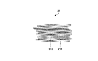
- FIG. 3 is an enlarged schematic view showing an example of the structure of the craze.
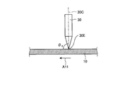
- FIG. 4 is a perspective view schematically showing an example of the craze processing apparatus.
- FIG. 5 is a side view schematically showing the vicinity of the blade of FIG. 4 in an enlarged manner.
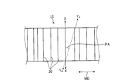
- FIG. 6 is a plan view schematically showing the first film having a hole-containing portion.
- polarizing plate includes not only a rigid member but also a flexible member such as a resin film.
- the directions of the constituent elements are “parallel”, “vertical” or “orthogonal” unless otherwise specified, within a range that does not impair the effects of the present invention, for example, usually ⁇ 5 °, preferably ⁇ 2.
- the error may be included in the range of 0 °, more preferably ⁇ 1 °.
- the MD direction is the flow direction of the film in the manufacturing line
- the TD direction is the direction parallel to the film surface and perpendicular to the MD direction. is there.
- the longitudinal direction of a long film may be referred to as the MD direction of the film
- the width direction may be referred to as the TD direction of the film.
- the "long" film means a film having a length of 5 times or more, preferably 10 times or more, and specifically a roll, with respect to the width. A film having such a length that it can be wound into a shape and stored or transported.
- the upper limit of the length of the long film is not particularly limited and may be, for example, 100,000 times or less the width.
- nx represents a refractive index in a direction perpendicular to the in-plane direction of the film, that is, the thickness direction and giving the maximum refractive index.
- ny represents the refractive index in the in-plane direction and in the direction orthogonal to the nx direction.
- nz represents the refractive index in the thickness direction.
- d represents the thickness of the film.
- the measurement wavelength is 590 nm unless otherwise specified.
- the viewing angle widening film of the present invention is a film for widening the viewing angle of a liquid crystal display device.
- the viewing angle widening film of the present invention has a plurality of hole-containing portions on at least one surface and has a rectangular shape.
- the rectangular shape may include a sheet and a long shape.
- the hole-containing portion contains holes, and the longitudinal direction of the hole-containing portion is 3 ° or more and 45 ° or less with respect to the short side direction of the viewing angle widening film, or the viewing angle is widened. It is 3 ° or more and 45 ° or less with respect to the long side direction of the film.
- FIG. 1 is a plan view schematically showing an example of a viewing angle widening film.
- the long viewing angle widening film 1 includes a plurality of linear hole-containing portions 20 that are parallel to each other.
- each of the hole-containing portions 20 is illustrated as a single thin line in FIG. 1, the hole-containing portion 20 is a region having a width and a depth, in which a large number of holes (not shown in FIG. 1) are included. ) Is provided.
- the hole-containing portion 20 shows a mode in which the hole-containing portion 20 is formed from one end of the viewing angle widening film 1 to the other end opposite to the end. It may be formed from one end of the viewing angle widening film to a position not reaching the other end, or may be formed at a position not reaching any end of the viewing angle widening film.
- ⁇ 1a indicates an angle with respect to the longitudinal direction of the hole-containing portion 20 (direction indicated by Y1-Y1) and the short side direction of the viewing angle widening film 1 (direction indicated by XX line).
- ⁇ 1b represents an angle formed by the longitudinal direction of the hole-containing portion 20 (direction indicated by Y1-Y1) and the long side direction of the viewing angle widening film 1 (direction indicated by ZZ line).
- the example shown in FIG. 1 is an example in which the longitudinal direction of the hole-containing portion is 3 ° or more and 45 ° or less with respect to the short side direction of the viewing angle widening film. That is, in the viewing angle widening film 1 shown in FIG. 1, ⁇ 1a is 3 ° or more and 45 ° or less. ⁇ 1a is preferably 5 ° or more, more preferably 6 ° or more, particularly preferably 7 ° or more, preferably 20 ° or less, more preferably 15 ° or less. By setting the range of ⁇ 1a as described above, it is possible to eliminate the moire interference phenomenon.
- the present invention also includes a mode in which the longitudinal direction of the hole-containing portion is 3 ° or more and 45 ° or less with respect to the long side direction of the viewing angle widening film.
- ⁇ 1b is 3 ° or more and 45 ° or less.
- ⁇ 1b is preferably 5 ° or more, more preferably 6 ° or more, particularly preferably 7 ° or more, preferably 20 ° or less, more preferably 15 ° or less.
- FIG. 2 is an enlarged schematic diagram schematically showing a hole-containing portion observed when the viewing angle widening film is observed in a plane.
- the vertical direction of the paper surface and the longitudinal direction of the hole containing portion are shown to be substantially parallel.
- L is the length of the hole-containing portion in the longitudinal direction
- L1 is the length from the center 20P of the hole-containing portion to 20A1 (0.4L)
- L2 is the length from the center 20P of the hole-containing portion to 20A2 ( 0.4 L).
- the term "longitudinal direction of the hole-containing portion” means that the lengths of the hole-containing portion in the longitudinal direction are L, and the positions 20A1 and 20A2 having a longitudinal length of ⁇ 0.4 L from the center 20P are connected.
- the hole-containing portion can be observed using, for example, an optical microscope or a digital microscope.
- the "longitudinal direction of the hole-containing portion” means, for example, the longitudinal direction of 80% or more of the hole-containing portion observed with an optical microscope, a digital microscope, etc.
- the hole-containing part contains holes, the light incident on the hole-containing part is scattered.
- the inclusion of pores causes the refractive index of the pore-containing portion to be different from that of the portion of the pore-containing layer where the pore-containing portion is not formed.
- the angle of the light scattering direction can be expanded. Without being bound to a particular theory, it is believed that the widening of the viewing angle is achieved by such light scattering over a wide range.
- the holes contained in the hole containing portion may or may not penetrate in the thickness direction of the viewing angle widening film.
- the structure since the hole-containing portion contains holes, the structure has a depth in the thickness direction of the viewing angle widening film.
- Each pore-containing portion usually has a large number of pores, but the structure of the pore-containing portion is not limited to this, and may be a single crack-shaped pore.
- the depth of the hole-containing portion may extend over the entire thickness of the hole-containing layer or may extend over only a part thereof.
- the plurality of hole-containing portions may be provided substantially parallel to each other.
- the hole-containing portions being “substantially parallel” to each other may be at an angle of more than 0 ° with each other within a range where the effect of the present invention can be obtained.
- the hole-containing portion may not have a perfect straight line but may have a partially folded shape, so that there are partially non-parallel portions and the angles formed by each other may be more than 0 °.
- the individual hole-containing parts usually have a substantially linear shape.
- the shape of the hole-containing portion being “substantially linear” includes the case where the hole-containing portion has a fold within the range in which the effect of the present invention can be obtained.
- Intervals P between adjacent hole-containing portions may be constant or random.
- the interval P between the adjacent hole-containing portions 20 is not constant but random. From the viewpoint of obtaining a high effect of widening the viewing angle, it is preferable that the interval P between the hole-containing portions is random.
- the distance P between the adjacent hole-containing portions is not particularly limited, but it is preferable that the distance is narrow from the viewpoint of suppressing a phenomenon such as moire interference and obtaining good display screen quality.
- the distance may be preferably 50 ⁇ m or less, more preferably 30 ⁇ m or less, and further preferably 5 ⁇ m or less.
- the maximum value of the intervals in the viewing angle widening film is equal to or less than the upper limit.
- the lower limit of the interval is not particularly limited, but may be 0.5 ⁇ m or more.
- a part or all of the plurality of hole-containing portions included in the viewing angle widening film is made of craze. From the viewpoint of ease of forming the hole-containing portion, the hole-containing portion is preferably made of craze.
- Craze refers to a substantially linear crack formed on the film. Crazes typically have fibrils formed between such fissures and voids formed therebetween as pores. Fibrils refer to fibers obtained by fibrillation of molecules constituting a resin.
- FIG. 3 is an enlarged schematic diagram showing an example of the structure of craze.
- the craze 21 has a large number of elongated fibrils 211 and voids 212 existing therebetween.
- the fibrils 211 usually extend in a direction substantially orthogonal to the longitudinal direction of the craze as the hole-containing portion.
- the craze having such a structure can be formed by subjecting a film to craze processing. By cracking the film and applying pressure to the film, cracks can be formed in the film, and in the gaps between the cracks, the molecules that form the resin can be made into fibers and fibrils and voids between them can be formed. . Details of craze processing will be described later.
- the fibril diameter is usually 5 nm to 50 nm, preferably 10 nm to 50 nm, more preferably 10 nm to 40 nm, and even more preferably 20 nm to 40 nm.
- the diameter of the void in the craze is usually 5 nm to 45 nm, preferably 10 nm to 30 nm.
- the width of the craze is usually 20 nm to 800 nm, preferably 30 nm to 600 nm, more preferably 40 nm to 300 nm.
- the craze height is usually 0.3 ⁇ m to 50 ⁇ m, preferably 0.4 ⁇ m to 30 ⁇ m, and more preferably 0.5 ⁇ m to 20 ⁇ m.
- the diameter of the fibrils here, the diameter of the voids and the width of the craze, and the value of the craze height are average values, specifically, observing any three points where the craze is expressed with a scanning electron microscope, It can be determined by measuring the size of fibrils and voids.
- the viewing angle widening film of the present invention may have a hole-containing portion on both surfaces, or may have a hole-containing portion on only one of the surfaces.
- the viewing angle widening film of the present invention may have a single-layer structure composed of one layer or a multi-layer structure composed of two or more layers.
- the hole-containing portion may be formed on at least one surface of the layer.
- the viewing angle widening film is preferably a resin film (resin layer).
- the pore-containing portion may be formed in a plurality of layers or may be formed in only one layer.
- the viewing angle widening film may have two or more resin layers, or may be a combination of a resin layer and a layer made of a material other than resin.
- the viewing angle widening film of the present invention preferably has two or more resin layers, and at least one of the resin layers is a layer containing a hole-containing portion.
- the thickness of the layer containing the pore-containing portion is preferably 0.2 ⁇ m or more, more preferably 0.5 ⁇ m or more, preferably 20 ⁇ m or less, more preferably 10 ⁇ m or less.
- the total thickness of the hole-containing layers is preferably within this range.
- the thickness of the pore-containing layer is within such a range, the pore-containing layer having the effect of the present invention can be easily constructed.
- the layer including the hole-containing portion has optical anisotropy
- its refractive index can be (nx + ny) / 2.
- the hole-containing portion is preferably formed in the resin layer.
- the resin forming the resin layer including the pore-containing portion preferably contains an alicyclic structure-containing polymer and a hydrocarbon compound.
- an example of the material forming the resin layer including the hole-containing portion will be described, but the present invention is not limited to this aspect, and other materials can be used.
- the resin constituting the layer containing the pore-containing portion contains a polymer having an alicyclic structure, which is a polymer having a low water absorption rate, and thus has a good visual field even after storage in a high humidity environment.
- the angular expansion characteristic can be maintained.
- Examples of the alicyclic structure-containing polymer include (1) norbornene-based polymer, (2) monocyclic cycloolefin-based polymer, (3) cyclic conjugated diene-based polymer, (4) vinyl alicyclic carbonization.
- Examples thereof include hydrogen-based polymers and hydrides of (1) to (4).
- the norbornene-based polymer and its hydride are preferable from the viewpoint of heat resistance, mechanical strength and the like.
- Examples of the norbornene-based polymer include ring-opening polymers of norbornene monomers, ring-opening copolymers of norbornene monomers with other monomers capable of ring-opening copolymerization, and hydrides thereof; addition polymers of norbornene monomers, Examples thereof include addition copolymers of the norbornene monomer and other copolymerizable monomers.
- a hydride of a ring-opening polymer of a norbornene monomer and a hydride of a ring-opening copolymer of a norbornene monomer and another monomer capable of ring-opening copolymerization are particularly preferable from the viewpoint of transparency.
- the polystyrene-equivalent or polyisoprene-equivalent weight average molecular weight of the alicyclic structure-containing polymer measured by gel permeation chromatography is usually 5,000 or more, preferably 10,000 or more, and more preferably 15,000 or more. And is usually 50,000 or less, preferably 45,000 or less, more preferably 40,000 or less.
- the cyclic hydrocarbon group-containing compound hydride unit [I] is obtained by polymerizing a cyclic hydrocarbon group-containing compound, and further, if the unit obtained by such polymerization has an unsaturated bond, the unsaturated bond is formed. It is a structural unit having a structure obtained by hydrogenation. However, the cyclic hydride group-containing compound hydride unit [I] includes a unit obtained by any production method as long as it has the structure.
- the cyclic hydride group-containing compound hydride unit [I] is preferably a structural unit obtained by polymerization of an aromatic vinyl compound. More specifically, it is a structural unit (aromatic vinyl compound hydride unit [I]) having a structure obtained by polymerizing an aromatic vinyl compound and hydrogenating its unsaturated bond.
- the aromatic vinyl compound hydride unit [I] includes a unit obtained by any manufacturing method as long as it has the structure.
- a structural unit having a structure obtained by polymerizing styrene and hydrogenating its unsaturated bond may be referred to as a styrene hydride unit.
- the styrene hydride unit also includes a unit obtained by any production method as long as it has the structure.
- Examples of the aromatic vinyl compound hydride unit [I] include structural units represented by the following structural formula (1).
- R c represents an alicyclic hydrocarbon group.
- R c include cyclohexyl groups such as cyclohexyl groups; decahydronaphthyl groups and the like.
- R 1 , R 2 and R 3 are each independently a hydrogen atom, a chain hydrocarbon group, a halogen atom, an alkoxy group, a hydroxyl group, an ester group, a cyano group, an amide group or an imide group.
- R 1 , R 2 and R 3 are preferably a hydrogen atom and a chain hydrocarbon group having 1 to 6 carbon atoms from the viewpoint of heat resistance, low birefringence and mechanical strength.
- the chain hydrocarbon group is preferably a saturated hydrocarbon group, more preferably an alkyl group.
- aromatic vinyl compound hydride unit [I] include structural units represented by the following formula (1-1).
- the structural unit represented by the formula (1-1) is a styrene hydride unit.
- hydride unit [I] of the cyclic hydrocarbon group-containing compound those having stereoisomers can be used in any stereoisomers.
- the cyclic hydrocarbon group-containing compound hydride unit [I] only one type may be used, or two or more types may be used in combination at an arbitrary ratio.
- the chain hydrocarbon compound hydride unit [II] is obtained by polymerizing a chain hydrocarbon compound and further hydrogenating the unsaturated bond if the unit obtained by such polymerization has an unsaturated bond. Is a structural unit having a structure described below. However, the chain hydrocarbon compound hydride unit [II] includes a unit obtained by any production method as long as it has the structure.
- the chain hydrocarbon compound hydride unit [II] is preferably a structural unit obtained by polymerization of a diene compound. More specifically, a structural unit having a structure obtained by polymerizing a diene compound and further hydrogenating the unsaturated bond if the unit obtained by such polymerization has an unsaturated bond (diene compound hydrogen Compound unit [II]).
- the diene compound hydride unit [II] includes a unit obtained by any manufacturing method as long as it has the structure.
- a structural unit having a structure obtained by polymerizing isoprene and hydrogenating its unsaturated bond may be referred to as an isoprene hydride unit.
- the isoprene hydride unit also includes a unit obtained by any production method as long as it has the structure.
- the diene compound hydride unit [II] is preferably a structural unit obtained by polymerization of a conjugated diene compound. More specifically, it preferably has a structure obtained by polymerizing a conjugated diene compound such as a chain conjugated diene compound and hydrogenating the unsaturated bond. Examples thereof include a structural unit represented by the following structural formula (2) and a structural unit represented by the structural formula (3).
- R 4 to R 9 are each independently a hydrogen atom, a chain hydrocarbon group, a halogen atom, an alkoxy group, a hydroxyl group, an ester group, a cyano group, an amide group, an imide group, a silyl group. Or represents a chain hydrocarbon group substituted with a polar group (halogen atom, alkoxy group, hydroxyl group, ester group, cyano group, amide group, imide group, or silyl group).
- R 4 to R 9 are preferably a hydrogen atom and a chain hydrocarbon group having 1 to 6 carbon atoms from the viewpoint of heat resistance, low birefringence, mechanical strength and the like.
- the chain hydrocarbon group is preferably a saturated hydrocarbon group, more preferably an alkyl group.
- R 10 to R 15 are each independently a hydrogen atom, a chain hydrocarbon group, a halogen atom, an alkoxy group, a hydroxyl group, an ester group, a cyano group, an amide group, an imide group or a silyl group. Or represents a chain hydrocarbon group substituted with a polar group (halogen atom, alkoxy group, hydroxyl group, ester group, cyano group, amide group, imide group, or silyl group).
- R 10 to R 15 are preferably a hydrogen atom and a chain hydrocarbon group having 1 to 6 carbon atoms from the viewpoint of heat resistance, low birefringence, mechanical strength and the like.
- the chain hydrocarbon group is preferably a saturated hydrocarbon group, more preferably an alkyl group.
- diene compound hydride unit [II] include structural units represented by the following formulas (2-1) to (2-3).
- the structural units represented by the formulas (2-1) to (2-3) are isoprene hydride units.
- any of the stereoisomers of the chain hydrocarbon compound hydride unit [II] having stereoisomers can be used.
- the chain hydrocarbon compound hydride unit [II] only one kind may be used, or two or more kinds may be used in combination at an arbitrary ratio.
- the hydrogenated block copolymer [G] preferably has a triblock molecular structure having one block [E] per molecule and two blocks [D] connected to both ends thereof per molecule. That is, the hydrogenated block copolymer [G] has one block [E] per molecule; and a cyclic hydride group-containing compound hydride unit [I] linked to one end of the block [E].
- the total of the block [D1] and the block [D2] and the block [D1] falls within a specific range.
- the weight ratio (D1 + D2) / E is preferably 45/55 or more, more preferably 50/50 or more, preferably 89/11 or less, more preferably 86/14 or less.
- the weight ratio of the block [D1] and the block [D2] is preferably from the viewpoint of easily obtaining a pore-containing layer having preferable properties. It is preferable that D1 / D2 falls within a specific range. Specifically, the weight ratio D1 / D2 is preferably 1 or more, more preferably 3 or more, particularly preferably 5 or more, preferably 15 or less, more preferably 14 or less, and particularly preferably 13 or less.
- the weight average molecular weight Mw of the hydrogenated block copolymer [G] is preferably 50,000 or more, more preferably 55,000 or more, particularly preferably 60,000 or more, preferably 85,000 or less, more preferably 80,000 or less, particularly preferably 75,000. It is the following. When the weight average molecular weight Mw is within the above range, it is possible to easily obtain a resin layer having a hole-containing portion having preferable properties.
- the molecular weight distribution (weight average molecular weight (Mw) / number average molecular weight (Mn)) of the hydrogenated block copolymer [G] is preferably 2.0 or less, more preferably 1.7 or less, and particularly preferably 1.5. It is below, preferably 1.0 or above. When the weight average molecular weight Mw is within the above range, the polymer viscosity can be lowered and the moldability can be enhanced.
- the weight average molecular weight Mw and the number average molecular weight Mn of the hydrogenated block copolymer [G] can be measured as polystyrene equivalent values by gel permeation chromatography using tetrahydrofuran as a solvent.
- the block [D1] and the block [D2] each independently include only the cyclic hydrocarbon group-containing compound hydride unit [I], but other than the cyclic hydrocarbon group-containing compound hydride unit [I].
- the optional structural unit include structural units based on vinyl compounds other than the cyclic hydrocarbon group-containing compound hydride unit [I].
- the content of any structural unit in the block [D] is preferably 10% by weight or less, more preferably 5% by weight or less, and particularly preferably 1% by weight or less.
- the block [E] consists only of a chain hydrocarbon compound hydride unit [II], or consists only of a cyclic hydrocarbon group-containing compound hydride unit [I] and a chain hydrocarbon compound hydride unit [II]. However, it may contain any unit other than the units [I] and [II]. Examples of the optional structural unit include structural units based on vinyl compounds other than the units [I] and [II].
- the content of any structural unit in the block [E] is preferably 10% by weight or less, more preferably 5% by weight or less, and particularly preferably 1% by weight or less.
- the weight ratio [I] / [II] is preferably 0.1 or more, more preferably 0.2 or more, particularly preferably 0.3 or more, preferably 1.5 or less, more preferably 1.4 or less. It is particularly preferably 1.3 or less.
- the weight ratio [I] / [II] of the units [I] and [II] in the molecule of the hydrogenated block copolymer [G] is preferably 70/30 or more, more preferably 72/28 or more, It is particularly preferably 74/26 or more, preferably 89/11 or less, more preferably 85/15 or less, and particularly preferably 83/17 or less.
- the ratio of the units [I] and [II] is within the above range, it is possible to easily obtain a pore-containing layer having preferable properties.
- the method for producing the hydrogenated block copolymer [G] is not particularly limited, and any production method can be adopted.
- the hydrogenated block copolymer [G] for example, a monomer corresponding to the cyclic hydrocarbon group-containing compound hydride unit [I] and the chain hydrocarbon compound hydride unit [II] is prepared, and these are prepared. It can be produced by polymerizing and polymerizing the obtained polymer [F]. Specific production can be carried out by appropriately combining, for example, the method described in WO 2016/152871 and other known methods.
- the hydrogenation rate in the hydrogenation reaction is usually 90% or more, preferably 95% or more, more preferably 97% or more. By increasing the hydrogenation rate, low birefringence and thermal stability of the hydrogenated block copolymer [G] can be improved.
- the hydrogenation rate can be measured by 1 H-NMR.
- the resin forming the pore-containing layer preferably contains a hydrocarbon compound other than the alicyclic structure-containing polymer described above.
- the resin forming the hole-containing layer contains a hydrocarbon compound having a number average molecular weight of 200 to 1500, whereby holes capable of achieving the viewing angle widening property can be developed.
- the number average molecular weight of the hydrocarbon compound is 200 to 1500.
- the number average molecular weight of the hydrocarbon compound is preferably 300 or more, more preferably 500 or more, preferably 1400 or less, more preferably 1300 or less.
- hydrocarbon compounds examples include petroleum resins and plant-based hydrocarbon resins.
- the hydrocarbon compound may be not only a compound consisting of carbon atoms and hydrogen atoms but also a compound containing a small amount of oxygen atoms.
- it may be a compound having 1 or less oxygen atom with respect to 8 carbon atoms.
- the petroleum resin means a resin obtained by polymerizing diolefins and monoolefins in a fraction of a cracked oil produced as a by-product during the production of ethylene by steam cracking of petroleum by a known method.
- Examples of petroleum resins are C5-based petroleum resins (wherein the above-mentioned fraction is derived from C5 fractions such as isoprene, 1,3-pentadiene, cyclopentene, cyclopentadiene, dicyclopentadiene (DCPD)), C9-based petroleum resins.
- the above-mentioned fraction is made from C9 fraction such as vinyltoluene, ⁇ -methylstyrene, indene, alkylindene, etc.), C5 and C9 copolymerized petroleum resin, hydrogenated C5 petroleum resin, hydrogenated C9 Petroleum resin, petroleum resin which is a copolymer of DCPD and other compounds and its hydride (hydrogenated DCPD petroleum resin) (for example, copolymer of DCPD and C9 fraction, copolymer of DCPD and aromatic compound) Polymers and their hydrides).
- C9 fraction such as vinyltoluene, ⁇ -methylstyrene, indene, alkylindene, etc.
- C5 and C9 copolymerized petroleum resin hydrogenated C5 petroleum resin
- hydrogenated C9 Petroleum resin petroleum resin which is a copolymer of DCPD and other compounds and its hydride (hydrogenated DCPD petroleum resin) (for example, copolymer of DCPD and C9 fraction, copolymer of DC
- petroleum resin examples include "Arcon (registered trademark)” manufactured by Arakawa Chemical Industry Co., Ltd., “Petocol (registered trademark)” manufactured by Tosoh Corporation, and Idemitsu Petrochemical Co., Ltd. Examples include the product name “I-MARV” and the T-REZ H series manufactured by JXTG Energy Co., Ltd.
- Examples of the plant-based hydrocarbon resin include rosin acid, dimer acid (difunctional C36 compound, etc.), and various terpene resins (pinene resin, next terpene resin, aromatic modified terpene resin, terpene phenol resin, hydrogenated terpene resin). ) Is mentioned. More specific examples of the plant-based hydrocarbon resin include rosin derivatives manufactured by Arakawa Chemical Industry Co., Ltd., hydrogenated dimer acid manufactured by Croda Japan Co., Ltd., and terpene resins manufactured by Yasuhara Chemical Co., Ltd. .
- the resin forming the pore-containing layer may contain one kind or two or more kinds of hydrocarbon compounds.
- the hydrocarbon compound is preferably hydrogenated petroleum resin, and more preferably one or more selected from hydrogenated C9 petroleum resin and hydrogenated DCPD petroleum resin.
- the hydrocarbon compound preferably has a softening point of 90 ° C or higher and 150 ° C or lower.
- the softening point of the hydrocarbon compound is more preferably 100 ° C. or higher, further preferably 110 ° C. or higher, and more preferably 145 ° C. or lower.
- the proportion of the hydrocarbon compound in the resin constituting the pore-containing layer is preferably 0.5% by weight or more, more preferably 5% by weight or more, based on the total amount of the alicyclic structure-containing polymer and the hydrocarbon compound. %, Preferably 40% by weight or less, more preferably 35% by weight or less.
- the glass transition temperature (Tg) of the resin forming the resin layer including the pore-containing portion is preferably 115 ° C. or higher, more preferably 118 ° C. or higher, still more preferably 120 ° C. or higher.
- the upper limit of the glass transition temperature is not particularly limited, but is preferably 160 ° C or lower, more preferably 150 ° C or lower.
- the resin that constitutes the resin layer including the pore-containing portion may optionally contain an optional component other than the alicyclic structure-containing polymer and the hydrocarbon compound.
- optional components include ultraviolet absorbers, antioxidants, heat stabilizers, light stabilizers, antistatic agents, dispersants, chlorine scavengers, flame retardants, crystallization nucleating agents, strengthening agents, antiblocking agents, antifogging agents.
- the resin forming the resin layer including the hole-containing portion preferably contains an ultraviolet absorber.
- ultraviolet absorbers examples include oxybenzophenone compounds, benzotriazole compounds, salicylate compounds, benzophenone ultraviolet absorbers, benzotriazole ultraviolet absorbers, acrylonitrile ultraviolet absorbers, triazine compounds, nickel complex salt compounds, And inorganic powders.
- UV absorbers examples include 2,2'-methylenebis (4- (1,1,3,3-tetramethylbutyl) -6- (2H-benzotriazol-2-yl) phenol), 2- ( 2'-hydroxy-3'-tert-butyl-5'-methylphenyl) -5-chlorobenzotriazole, 2,4-di-tert-butyl-6- (5-chlorobenzotriazol-2-yl) phenol, 2,2'-dihydroxy-4,4'-dimethoxybenzophenone and 2,2 ', 4,4'-tetrahydroxybenzophenone can be mentioned.
- a particularly suitable example is 2,2'-methylenebis (4- (1,1,3,3-tetramethylbutyl) -6- (2H-benzotriazol-2-yl) phenol).
- the content of the ultraviolet absorber is preferably 0.5 to 5% by weight per 100% by weight of the resin.
- the viewing angle widening film of the present invention may include only the resin layer including the hole-containing portion, or may include the resin layer including the hole-containing portion and any resin layer that does not include the hole-containing portion in combination. .
- a useful viewing angle widening film can be formed by combining a resin layer containing a hole-containing portion with a resin layer other than the resin layer.
- An example of such an optional resin layer is a reinforcing layer having higher strength than the resin layer including the hole-containing portion.
- the resin layer including the hole-containing portion may have low strength by containing holes.
- a viewing angle widening film having both optical performance and strength can be obtained.
- the arbitrary resin layer is a protective layer provided on one or both of the front surface and the back surface of the resin layer including the hole-containing portion.
- the resin layer containing the hole-containing portion may have irregularities on its surface by containing pores.
- the protective layer may further have the function as the reinforcing layer described above.
- the viewing angle widening film of the present invention has a layer structure of 2 layers and 3 layers of skin layer / core layer / skin layer, the core layer is a hole-containing layer, and the skin layer is a reinforcing layer and / or a protective layer. Can function as a layer.
- Another example of the optional resin layer is an easy-adhesion layer for improving the adhesiveness between the viewing angle widening film and other members.
- the resin forming such a layer is not particularly limited, and any material having desired characteristics can be appropriately selected.
- the resin constituting the reinforcing layer and the protective layer as a polymer, a resin containing a polymer selected from polystyrene, polypropylene, polyethylene, polyester, polyamide, polyvinylidene fluoride, and an alicyclic structure-containing polymer can be mentioned.
- the resin constituting the reinforcing layer and the protective layer those having desired characteristics can be appropriately selected from the examples of these resins.
- the thickness of the viewing angle widening film is preferably 5 ⁇ m or more, more preferably 10 ⁇ m or more, still more preferably 20 ⁇ m or more.
- the upper limit is not particularly limited, but is preferably 100 ⁇ m or less, more preferably 70 ⁇ m or less, and further preferably 40 ⁇ m or less.
- the viewing angle widening film of the present invention may be a long film or a single film.
- the viewing angle widening film is manufactured as a long film from the viewpoint of increasing manufacturing efficiency.
- a single-viewing angle expansion film can be manufactured by cutting out a long viewing angle expansion film into a desired shape.
- the viewing angle widening film of the present invention may be a film having small optical anisotropy and being substantially optically isotropic, or may be an optically anisotropic film.
- such anisotropy may be due to the hole-containing layer, or may be due to a layer other than the hole-containing layer, It may be due to both of them.
- the viewing angle widening film of the present invention is an optically anisotropic film
- its in-plane retardation Re is preferably 360 nm or less, more preferably 330 nm or less, still more preferably 300 nm or less.
- the lower limit is not particularly limited, but is preferably 10 nm or more, more preferably 20 nm or more, and further preferably 30 nm or more.
- the retardation Rth in the thickness direction is preferably 400 nm or less, more preferably 350 nm or less, and further preferably 300 nm or less.
- the lower limit is not particularly limited, but is preferably 10 nm or more, more preferably 20 nm or more, and further preferably 30 nm or more.
- the total light transmittance of the viewing angle widening film is preferably 70% or more, more preferably 80% or more.
- the light transmittance can be measured using a spectrophotometer (UV-Vis near-infrared spectrophotometer "V-570" manufactured by JASCO Corporation) according to JIS K0115.
- the method for producing a viewing angle widening film of the present invention comprises the step 1 of forming a hole-containing portion on at least one surface of the first film, and stretching the first film subjected to the step 1 to obtain the hole-containing portion. And step 2 of expanding the hole diameter of.
- Step 1 is a step of forming a hole containing portion on at least one surface of the first film.
- the first film is a film used for forming the hole-containing portion, and may be referred to as a "material film”.
- the layer structure of the material film is not particularly limited, and may be a layer structure suitable for the desired layer structure of the viewing angle widening film.
- it may have a layer structure including a resin layer including a hole-containing portion and a layer other than the resin layer. More specifically, by combining a layer that can be a layer containing pore-containing portions by craze processing and a layer in which craze does not occur even by such craze processing, a resin layer containing pore-containing portions, and a resin layer other than that.
- Examples of the material film manufacturing method include an injection molding method, an extrusion molding method, a press molding method, an inflation molding method, a blow molding method, a calender molding method, a cast molding method, and a compression molding method.
- the conditions such as the temperature of the molten resin when manufacturing the material film can be appropriately changed according to the type of the material film, and can be performed under known conditions.
- examples of the method for producing the material film include coextrusion T-die method, coextrusion inflation method, coextrusion lamination method, dry lamination, cocasting method, and coating molding. There is a law.
- the material film has two or more resin layers
- a resin which is a material of one layer (layer A) is molded into a film, and the resin which is a material of layers other than the layer A is dissolved in a solvent in the film-shaped layer A.
- a material film can be obtained by applying the coating liquid thus obtained and drying.
- the material film may be an unstretched unstretched film or a stretched stretched film. Further, a film having a multilayer structure obtained by laminating a stretched film formed of a certain material and an unstretched film formed of the same material may be used as the material film.
- the hole-containing portion is formed on the surface of the material film, whereby the first film including the hole-containing portion is obtained.
- Examples of a specific method for forming the hole-containing portion include craze processing. By performing craze processing, it is possible to efficiently produce a viewing angle widening film in which the hole-containing portion is made of craze.
- FIG. 4 is a perspective view schematically showing an example of the craze processing apparatus
- FIG. 5 is a side view schematically showing the vicinity of the blade of FIG. 4 in an enlarged manner.
- the device is observed from the TD direction.
- the craze processing apparatus 100 includes a payout roll 41, transport rolls 42 and 43, and a blade 30.
- the blade 30 includes an edge 30E extending in a direction parallel to the TD direction.
- the first film 10 transported in the direction of the arrow A11 from the payout roll 41 is supported by the transport rolls 42 and 43 while being urged against the edge 30E of the blade 30. Be transported. Thereby, pressure can be applied to the first film 10.
- the surface of the first film 10 is deformed by pressure, the hole-containing portion 20 extending in the direction substantially parallel to the TD direction is formed, and the first film 11 including the hole-containing portion is obtained.
- the longitudinal direction of the hole-containing portion is parallel to the TD direction (XX line direction).
- the angle at which the blade 30 contacts the first film 10 can be appropriately adjusted to the angle at which a desired craze is formed.
- the angle is represented as an angle ⁇ x formed by the center line 30C of the blade 30 observed from the extension direction of the edge 30E and the downstream surface of the first film 10.
- the angle ⁇ x is preferably 10 ° to 60 °, more preferably 15 ° to 50 °, even more preferably 20 ° to 40 °.
- the tension of the material film when the blade is pressed against the first film can be appropriately adjusted to a value at which a desired craze is formed.
- the tension is preferably 100 N / m to 1000 N / m, more preferably 300 N / m to 800 N / m.
- craze may occur in all of the two or more resin layers, Crazing may occur only in the resin layer. Further, in the case where craze occurs in only a part of the resin layers, craze may occur in the outermost surface layer and craze may occur in the inner layer.
- a material film consisting of a core layer made of a material having a relatively small tensile elongation and brittleness and skin layers made of a relatively flexible material on the front and back surfaces thereof is subjected to craze processing, the craze is applied only to the core layer. Can occur.
- Such a film can also be used as a material for the viewing angle widening film of the present invention.
- Step 2 is a step of stretching the first film subjected to Step 1 to expand the pore diameter of the pore-containing portion.
- the pore diameter of the pore-containing portion (pore diameter) is expanded, whereby a viewing angle widening film exhibiting a viewing angle widening effect can be obtained.
- the method for stretching the first film including the pore-containing portion obtained by performing step 1 is not particularly limited, but diagonal stretching is preferable. A specific example of a suitable stretching method will be described with reference to FIG. FIG. 6 is a plan view schematically showing the first film 11 having a hole-containing portion.
- the stretching of the first film 11 including the hole-containing portion is performed in the short side direction (X- It is preferable to perform stretching (oblique stretching) at an angle indicated by ⁇ A with respect to the X-ray direction).
- the stretching angle ⁇ A is 3 ° or more and 45 °, it is possible to obtain a viewing angle widening film in which the angle ⁇ 1a formed by the longitudinal direction of the hole-containing portion and the short side direction of the film is 3 ° or more and 45 °.
- the viewing angle widening film in which the angle ⁇ 1b formed by the longitudinal direction of the hole-containing portion and the long-side direction of the film is 3 ° or more and 45 ° or less is a hole-containing portion with respect to the TD direction (XX line direction) shown in FIG.
- the first resin film 11 formed by stretching the first film 11 in which the longitudinal directions of the first resin film 11 are parallel to each other in the direction indicated by ⁇ A with respect to the short side direction (XX line direction) of the film It can be manufactured by cutting the stretched first resin film into a rectangular shape having a long side in the direction.
- the stretching can be performed using a known stretching device.
- the stretching device include a longitudinal uniaxial stretching machine, a tenter stretching machine, a bubble stretching machine, and a roller stretching machine.
- the stretching temperature of the first film 11 including the hole-containing portion is preferably It is (Tg-30 ° C) or higher, more preferably (Tg-10 ° C) or higher, preferably Tg or lower, more preferably (Tg-5) ° C or lower.
- Tg represents the glass transition temperature of the resin forming the resin layer in which the hole-containing portion is formed.
- the stretch ratio is preferably 1.05 or more, more preferably 1.1 or more, preferably 2.0 or less, more preferably 1.5 or less.
- the total stretching ratio represented by the product of the stretching ratios in each stretching direction falls within the above range.
- the hole-containing portion is formed by a blade provided with an edge 30E extending in a direction parallel to the TD direction, but the angle of the blade is, for example, the short side direction or the long side of the first film.
- the hole-containing portion may be formed by arranging at a predetermined angle with respect to the side direction.
- the first film including the hole-containing portion may be the viewing angle widening film, but the first film including the hole-containing portion may be used.
- Performing the step of stretching the film to expand the pore diameter (step 2) is preferable because a viewing angle widening film in which the pore diameter of the pore-containing portion is expanded can be obtained.
- the viewing angle widening film of the present invention is a film for widening the viewing angle. Specifically, it can be used for widening the viewing angle of a display device such as a liquid crystal display device.
- the function of the viewing angle widening film of the present invention is not limited to this.
- the viewing angle widening film of the present invention may exhibit not only the function as the viewing angle widening film but also the other functions.
- functions other than the viewing angle widening film include a function as a protective film, a function as a retardation film, and a function as an optical compensation film.
- it can be preferably used as a polarizing plate that also exhibits a function as a polarizing plate protective film.
- the polarizing plate of the present invention includes the viewing angle widening film of the present invention and a polarizer.
- the viewing angle widening film can also function as a polarizing plate protective film.
- a polarizing plate can be manufactured by, for example, laminating a polarizer and a viewing angle widening film.
- the polarizer and the viewing angle widening film may be directly attached without an adhesive layer, or may be attached via an adhesive layer formed of an adhesive. .
- another protective film may be interposed between the polarizer and the viewing angle widening film.
- the surface may be located on the polarizer side or on the opposite side to the polarizer.
- the polarizing plate of the present invention may be provided with a viewing angle widening film on only one surface of the polarizer, or may be provided with a viewing angle widening film on both surfaces.
- the polarizing plate may be provided with any film other than the viewing angle expansion film that can function as a protective film on the other surface of the polarizer.
- the visual field expanding film can be in direct contact with the polarizer.
- the polarizing plate of the present invention may further have another layer interposed between the visual field widening film and the polarizer.
- the field-of-view magnifying film can function as a protective film for protecting the polarizer in the polarizing plate.
- the polarizing plate and the liquid crystal display device of the present invention can be configured by simply adding a visual field expanding film to the existing liquid crystal display device.
- a polarizing plate and a liquid crystal display device of the present invention can be constructed by combining with a film.
- the angle formed by the longitudinal direction of the hole-containing portion and the direction perpendicular to the absorption axis of the polarizer is 3 ° or more and 45 ° or less. preferable. Accordingly, the viewing angle of the VA mode liquid crystal display device can be expanded.
- the polarizing plate of the present invention when used in a TN mode liquid crystal display device to be described later, when the display screen of the liquid crystal display device is viewed from an oblique direction, the azimuth angle at which gradation is inverted and the longitudinal direction of the hole-containing portion are formed. It is preferable that the angle is 90 ° + ⁇ 1 and ⁇ 1 is 3 ° or more and 45 ° or less. As a result, the viewing angle of the TN mode liquid crystal display device can be expanded.
- the polarizer can be produced, for example, by adsorbing iodine or a dichroic dye on a polyvinyl alcohol film and then uniaxially stretching it in a boric acid bath.
- it can be produced by adsorbing iodine or a dichroic dye on a polyvinyl alcohol film, stretching the film, and further modifying a part of the polyvinyl alcohol unit in the molecular chain into a polyvinylene unit.
- a polarizer having a function of separating polarized light into reflected light and transmitted light such as a grid polarizer, a multilayer polarizer, and a cholesteric liquid crystal polarizer may be used.
- a polarizer containing polyvinyl alcohol is preferable.
- the polarization degree of the polarizer is preferably 98% or more, more preferably 99% or more.
- the average thickness of the polarizer is preferably 5 ⁇ m to 80 ⁇ m.
- any optically transparent adhesive may be used.
- adhesives include water-based adhesives, solvent-based adhesives, two-component curable adhesives, ultraviolet curable adhesives, and pressure-sensitive adhesives.
- a water-based adhesive is preferable, and a polyvinyl alcohol-based water-based adhesive is particularly preferable.
- the adhesive may be used alone or in combination of two or more kinds at an arbitrary ratio.
- the average thickness of the adhesive layer is preferably 0.05 ⁇ m or more, more preferably 0.1 ⁇ m or more, preferably 5 ⁇ m or less, more preferably 1 ⁇ m or less.
- the method of bonding the viewing angle widening film and the polarizer there is no limitation on the method of bonding the viewing angle widening film and the polarizer.
- the laminating method after applying an adhesive to one surface of the polarizer as needed, the polarizer and the viewing angle widening film are laminated using a roll laminator, and dried if necessary. The method to do is mentioned. The drying time and the drying temperature are appropriately selected according to the type of adhesive.
- the viewing angle widening film of the present invention and the polarizing plate of the present invention can be used in a liquid crystal display device.
- a known liquid crystal cell such as a TN (Twisted Nematic) mode, a VA (Virtual Alignment) mode, and an IPS (In-Plane Switching) mode can be used as a liquid crystal cell constituting the liquid crystal display device.
- the TN mode and the VA mode are preferable from the viewpoint of effectively expanding the viewing angle.
- the viewing angle widening film of the present invention or the polarizing plate of the present invention is preferably used in a TN mode liquid crystal display device.
- the TN mode liquid crystal display device of the present invention is provided with the polarizing plate of the present invention and the TN mode liquid crystal cell in this order from the viewer side, and the viewing side of the polarizing plate is the viewing angle widening film side.
- the azimuth angle that is gradation-reversed and the longitudinal direction of the hole-containing portion are 90 ° + ⁇ 1 ( ⁇ 1 is 3 ° or more and 45 ° or less). is there.
- the azimuth angle at which the gradation is reversed means that the polarizing plate of the present invention was replaced with a polarizing plate having the same structure as the polarizing plate of the present invention except that the viewing angle widening film of the present invention was not provided. This is the azimuth angle at which the gradation is reversed.
- TN-mode liquid crystal display devices usually include a polarizing plate and a light source on the side opposite to the viewing side of the TN-mode liquid crystal cell.
- the polarizing plate arranged on the side opposite to the viewing side the polarizing plate of the present invention may be used, or a polarizing plate other than the polarizing plate of the present invention such as a known polarizing plate may be used.
- the light source any light source such as a known light source can be used.
- the viewing side means the side where the observer of the displayed image is located when using the liquid crystal display device.
- the display screen When the liquid crystal display is operated to change from a black display state (a state where black is displayed on the entire screen) to a white display state (a state where white is displayed on the entire screen) by gradually increasing the brightness, the display screen The brightness of will also gradually increase. For example, when an operation is performed to display an 8-bit gray scale (a black display state is 0, a white display state is 255, and an intermediate gradation is represented by a value of 0 to 255) on the display screen of the liquid crystal display device, the scale is As 0 is increased from 0 to 255, the brightness of the display screen also increases. However, depending on the viewing direction, when the operation of gradually increasing the brightness is performed, the brightness of the display screen may decrease in contrast.
- the gradation inversion may be observed at a certain azimuth angle when the display screen of the liquid crystal display device is viewed from an oblique direction.
- the angle formed by the azimuth angle at which the gradation is inverted when the display screen is viewed obliquely and the longitudinal direction of the hole-containing portion is 90 ° + ⁇ 1 ( ⁇ 1 is 3 ° or more and 45 ° or less). ), It is possible to reduce such gradation inversion and widen the viewing angle.
- the azimuth angle for gradation inversion is not limited to one direction, but may be two directions or an angle range having a certain degree of spread. In that case, the direction in which the viewing angle is most desired to be widened can be determined, and the longitudinal direction of the hole-containing portion can be set in the direction perpendicular to the direction.
- the angle formed by the absorption axis of the polarizer and the longitudinal direction of the hole-containing portion is 45 ° + ⁇ 1 ( ⁇ 1 is 3 ° or more and 45 ° or less). Some can be preferably used.
- Normal TN-mode liquid crystal display device having a rectangular display screen, the display screen is upright in a substantially vertical direction, and is used in a state in which the long side direction of the rectangle is a horizontal direction and the short side direction is a substantially vertical direction. In many cases, gradation inversion is often observed when observed from the lower side. In a normal TN-mode liquid crystal display device, the polarizer often forms an angle of 45 ° between its absorption axis and the horizontal direction of the display screen.
- the polarizing plate of the present invention has an angle between the absorption axis of the polarizer and the longitudinal direction of the hole-containing portion of 45 ° + ⁇ 1 ( ⁇ 1 is 3 ° or more and 45 ° or less),
- the angle formed by the absorption axis and the horizontal direction of the display screen is 45 °, and the angle formed by the longitudinal direction of the hole-containing portion and the horizontal direction of the display screen is inclined by ⁇ 1 (3 ° or more and 45 ° or less) from the parallel direction easily. Therefore, the viewing angle of the TN mode liquid crystal display device can be easily expanded.
- VA mode liquid crystal display device The viewing angle widening film of the present invention or the polarizing plate of the present invention is also preferably used in a VA mode liquid crystal display device.
- the VA mode liquid crystal display device of the present invention is provided with the polarizing plate of the present invention and the VA mode liquid crystal cell in this order from the viewing side, and the polarizing plate has a viewing angle expansion film side as the viewing side. Will be arranged.
- VA mode liquid crystal display devices usually include a polarizing plate and a light source on the side opposite to the viewing side of the VA mode liquid crystal cell.
- the polarizing plate arranged on the side opposite to the viewing side the polarizing plate of the present invention may be used, or a polarizing plate other than the polarizing plate of the present invention such as a known polarizing plate may be used.
- the light source any light source such as a known light source can be used.
- the angle formed by the longitudinal direction of the hole-containing portion and the direction parallel to the absorption axis of the polarizer is 3 ° or more and 45 ° or less. Those having an angle between the longitudinal direction of the hole-containing portion and the direction perpendicular to the absorption axis of the polarizer of 3 ° or more and 45 ° or less can be preferably used.
- the relationship between the longitudinal direction of the hole-containing portion and the long side direction of the display screen is arranged at an angle of 3 ° or more and 45 ° or less from the parallel or 3 from the vertical.
- the arrangement is such that the angle is not less than 45 ° and not more than 45 °.
- the longitudinal direction of the hole-containing portion may be 3 ° or more and 45 ° or less from the direction perpendicular to the azimuth angle direction required to widen the viewing angle.
- the longitudinal direction of the hole containing portion is 3 ° with respect to the direction parallel to the short side direction. It is preferable that the arrangement is inclined at 45 ° or less.
- the longitudinal direction of the hole-containing portion may be an arrangement inclined by 3 ° or more and 45 ° or less from a direction parallel to the absorption axis of the polarizer or an arrangement inclined by 3 ° or more and 45 ° or less from a vertical direction. With such an arrangement, the viewing angle of the VA mode liquid crystal display device can be expanded.
- the viewing angle widening film of the present invention or the polarizing plate of the present invention is also preferably used in an IPS mode liquid crystal display device.
- the IPS mode liquid crystal display device of the present invention is provided with the polarizing plate of the present invention and the IPS mode liquid crystal cell in this order from the viewing side, and the polarizing plate has the viewing side on the viewing side and the viewing side. Will be arranged.
- An IPS-mode liquid crystal display device usually includes a polarizing plate and a light source on the side opposite to the viewing side of the IPS-mode liquid crystal cell.
- the polarizing plate arranged on the side opposite to the viewing side the polarizing plate of the present invention may be used, or a polarizing plate other than the polarizing plate of the present invention such as a known polarizing plate may be used.
- the light source any light source such as a known light source can be used.
- the angle formed by the longitudinal direction of the hole-containing portion and the direction parallel to the absorption axis of the polarizer is 3 ° or more and 45 ° or less. It is preferable to use one having an angle between the longitudinal direction of the hole-containing portion and the direction perpendicular to the absorption axis of the polarizer of 3 ° or more and 45 ° or less.
- the relationship between the longitudinal direction of the hole-containing portion and the long side direction of the display screen is arranged at an angle of 3 ° or more and 45 ° or less from the parallel or 3 from the vertical.
- the arrangement is such that the angle is not less than 45 ° and not more than 45 °.
- the longitudinal direction of the hole-containing portion may be 3 ° or more and 45 ° or less from the direction perpendicular to the azimuth angle direction required to widen the viewing angle.
- the longitudinal direction of the hole containing portion is 3 ° with respect to the direction parallel to the short side direction. It is preferable that the arrangement is inclined at 45 ° or less.
- the longitudinal direction of the hole-containing portion may be an arrangement inclined by 3 ° or more and 45 ° or less from a direction parallel to the absorption axis of the polarizer or an arrangement inclined by 3 ° or more and 45 ° or less from a vertical direction. With such an arrangement, the viewing angle of the IPS mode liquid crystal display device can be expanded.
- the color of each gradation from 0 (black) to 255 (white) on the 256 gradation gray scale was displayed, and the luminance was observed from the front direction and the direction of the polar angle of 75 °.
- the azimuth in the direction of the polar angle of 75 ° was the in-plane direction of the display device, which was perpendicular to the longitudinal direction of the hole-containing portion.
- the in-plane direction of the display device was perpendicular to the longitudinal direction of the hole-containing portion, and in the comparative example, the in-plane direction of the display device corresponding to each example.
- the normalized brightness was calculated with the brightness at the gray scale 0 being 0% and the brightness at the gray scale 255 being 100%, and the relationship between the gray scale and the standardized brightness was obtained.
- the absolute value of the difference between the normalized luminance in the front direction and the normalized luminance in the polar angle 75 ° direction is calculated for each grayscale gradation, and the maximum value of these values is obtained as ⁇ (%). It was A low ⁇ indicates that the viewing angle characteristics are good.
- the hole-containing portions formed in the viewing angle widening films manufactured in Examples and Comparative Examples were observed using a digital microscope (manufactured by Keyence Corporation).
- the "longitudinal direction of the hole-containing portion" is defined as the direction connecting the positions 20A1 and 20A2 whose length in the longitudinal direction from the center 20P is ⁇ 0.4L, where L is the total length of the hole-containing portion in the longitudinal direction. .
- the longitudinal direction of 80% or more of the hole-containing parts was defined as the "longitudinal direction of the hole-containing parts".
- Example 1 (1-1. Preparation of material film)
- a multi-layer film having a layer structure of two layers of two types of skin layer / core layer was produced.
- a resin film 1 (trade name: ZEONOR film, manufactured by Nippon Zeon Co., Ltd., glass transition temperature 126 ° C., thickness 48 ⁇ m) containing a norbornene-based polymer (described as “COP” in the table) is used. I was there.
- norbornene-based polymer 1 (trade name: Zeonex T62R, manufactured by Zeon Corporation) and hydrogenated C9-based petroleum resin 1 (trade name: Alcon P140, manufactured by Arakawa Chemical Industry Co., Ltd., number average) Molecular weight: 940, softening point: 140 ⁇ 5 ° C.) was used.
- the coating liquid 1 containing the material of the core layer (norbornene-based polymer 1 and hydrogenated C9-based petroleum resin 1) was applied to one surface of the resin film 1 using a die coater.
- Coating solution 1 was prepared by stirring 12 parts of norbornene-based polymer 1 and 3 parts of hydrogenated C9-based petroleum resin 1 together with 85 parts of cyclohexane for 24 hours.
- the coating amount of the coating liquid 1 was adjusted so that the thickness of the core layer after drying was 6 ⁇ m.
- the resin film 1 coated with the coating liquid 1 was dried in an oven at 85 ° C. for 5 minutes to obtain a material film.
- the resulting material film had a width of 300 mm, a skin layer thickness of 48 ⁇ m, and a core layer thickness of 6 ⁇ m.
- the glass transition temperature of the resin forming the core layer was 148 ° C.
- the proportion of hydrogenated C9 petroleum resin 1 (hydrocarbon compound) in the resin constituting the core layer was 20%.
- FIGS. 4 and 5 A viewing angle widening film was manufactured using the apparatus schematically shown in FIGS. 4 and 5.
- the first film 10 obtained in (1-1) is arranged so that the surface on the core layer side is in contact with the blade 30, and the first film 10 is pressed against the blade 30 to adjust the tension of the first film 10.
- Craze processing was carried out at 500 N / m in the direction of arrow A11 at a speed of 50 mm / min to obtain a first film 11 including a hole-containing portion.
- the direction of the edge 30E of the blade 30 was the width direction (TD direction) of the first film.
- the angle ⁇ x formed by the center line 30C of the blade 30 observed from the extension direction of the edge 30E and the downstream surface of the first film 10 was set to 20 °.
- the craze-processed film (first film 11 including a hole-containing portion) was stretched at a temperature of 130 ° C. in a direction of 5 ° with respect to its width direction (short side direction: XX line direction shown in FIG. 6) ( A viewing angle widening film 1 was obtained by continuously obliquely stretching in the direction of the angle ⁇ A shown in the drawing. In this viewing angle widening film, the longitudinal direction of the hole-containing portion was inclined by 5 ° with respect to the short side direction of the film.
- the hole-containing part of the obtained viewing angle widening film appeared on the core layer side.
- the hole-containing portion is a substantially linear craze, the longitudinal directions of the hole-containing portion are substantially parallel to each other, and are inclined 5 ° with respect to the TD direction (short side direction) of the viewing angle widening film. It was The spacing P between the pore-containing portions was a random spacing of 26 ⁇ m or less.
- the average value of the width of each hole-containing portion was 6.2 ⁇ m, and the average value of the depth (hole height) of the hole-containing portion was 5 ⁇ m. These values were obtained by selecting three arbitrary points on the craze film and observing a 25 ⁇ m square area with a scanning electron microscope.
- the viewing angle widening film obtained in (1-2) was attached to the polarizing plate on the viewing side surface of a linearly polarized light VA mode liquid crystal display device (BenQ, 27 inches, model GW2760HS).
- a linearly polarized light VA mode liquid crystal display device (BenQ, 27 inches, model GW2760HS).
- the angle formed by the direction perpendicular to the absorption axis of the polarizer in the viewing side polarizing plate and the longitudinal direction of the hole-containing portion of the viewing angle widening film is ⁇ A (5 ° in Example 1), and The directions were adjusted so that the angle formed by the longitudinal direction of the hole-containing portion and the direction parallel to the short side direction of the rectangular display screen was ⁇ A (5 ° in Example 1).
- the viewing angle widening film was attached such that the surface on the side where the hole-containing portion was formed was the viewing side. Thereby, the liquid crystal display device of the present invention was obtained.
- Examples 2 to 5 A liquid crystal display device and its components were obtained and evaluated by the same operations as in Example 1 except for the following changes.
- the stretching direction of the craze-processed film was set to be the stretching angle ( ⁇ A) described in each table with respect to the width direction (short side direction: XX line direction shown in FIG. 6) of the film.
- the hole-containing parts of the viewing angle widening films obtained in Examples 2 to 5 and Comparative Examples 2 to 3 were developed in the core layer.
- the hole containing portion is a substantially linear craze, the longitudinal direction of the hole containing portion is substantially parallel to each other, at an angle of ⁇ A with respect to the TD direction (short side direction) of the viewing angle widening film, It was inclined.
- the spacing P between the pore-containing portions was a random spacing of 26 ⁇ m or less.
- the average value of the width of each hole-containing portion was 6.2 ⁇ m, and the average value of the depth (hole height) of the hole-containing portion was 5 ⁇ m.
- the hole-containing portion of the viewing angle widening film obtained in Comparative Example 1 appeared in the core layer.
- the hole-containing portion was a substantially linear craze, and the longitudinal directions of the hole-containing portion were substantially parallel to each other and parallel to the TD direction (short side direction) of the viewing angle widening film.
- the spacing P between the pore-containing portions was a random spacing of 26 ⁇ m or less.
- the average value of the width of each hole-containing portion was 6.2 ⁇ m, and the average value of the depth (hole height) of the hole-containing portion was 5 ⁇ m.
- Example 4 A liquid crystal display device and its components were obtained and evaluated by the same operations as in Example 1 except for the following changes.
- the stretching temperature was 140 ° C.
- the hole-containing portion of the viewing angle widening film obtained in Comparative Example 4 appeared in the core layer.
- the pore-containing portion was a substantially linear craze, and the longitudinal directions of the pore-containing portion were substantially parallel to each other and substantially parallel to the TD direction of the film.
- the interval P between the hole-containing parts was a random interval of 26 ⁇ m or less, and the average depth (height) of the hole-containing parts was 5 ⁇ m. Since the craze was filled during the stretching, the average width of the hole-containing portion was 0.01 ⁇ m.
- the contrast ratios in Examples in which the longitudinal direction of the hole-containing portion is 3 ° or more and 45 ° or less with respect to the TD direction (short side direction) of the viewing angle widening film. was 2100 or more, ⁇ was 22 or less, and the evaluation of glare was A or B. That is, in the example using the viewing angle widening film of the present invention, a liquid crystal display device was obtained which was compatible with a high contrast ratio and a wide viewing angle and was able to eliminate the moire interference phenomenon.
Abstract
A viewing angle expansion film for expanding a viewing angle, wherein the viewing angle expansion film is provided with a plurality of hole-including parts on at least one surface thereof and has a rectangular shape, the hole-including parts include holes, and the longitudinal direction of the hole-including parts is angled 3° to 45° with respect to the short-side direction of the viewing angle expansion film, or 3° to 45° with respect to the long-side direction of the viewing angle expansion film. Also provided are a polarizing plate and a liquid crystal display device provided with the viewing angle expansion film, and a method for manufacturing a viewing angle expansion film.
Description
本発明は、視野角拡大フィルム、偏光板、液晶表示装置、及び視野角拡大フィルムの製造方法に関する。
The present invention relates to a viewing angle widening film, a polarizing plate, a liquid crystal display device, and a manufacturing method of the viewing angle widening film.
TNモード及びVAモードの液晶表示装置は、技術が確立され比較的安価に供給可能である一方、表示面を斜め方向から観察した場合の表示品質が劣り、利用可能な視野角が狭い場合が多い。具体的には、画面に表示した画像の明るさと、画像を観察して測定される輝度との関係が、正面から観察した場合と斜め方向から観察した場合とで大きく相違し、液晶表示装置の視認が困難となりうる。このため、TNモードの液晶表示装置は、従来は中小型テレビやパーソナルコンピュータなどの決まった角度から視認する表示装置に主に採用されてきた。しかしながら、近年、タブレット型端末などの、広視野角での視認性が求められる装置でも、視野角を拡大するための手段と共に、これらのモードの液晶表示を用いることが試みられている。
The TN mode and VA mode liquid crystal display devices have established technology and can be supplied at a relatively low cost, but on the other hand, the display quality is poor when the display surface is observed from an oblique direction, and the usable viewing angle is often narrow. . Specifically, the relationship between the brightness of the image displayed on the screen and the luminance measured by observing the image is significantly different between the case of observing from the front and the case of observing from an oblique direction. It can be difficult to see. For this reason, the TN-mode liquid crystal display device has been conventionally mainly used for a display device such as a small-to-medium-sized television or a personal computer which is viewed from a fixed angle. However, in recent years, it has been attempted to use a liquid crystal display of these modes together with a means for enlarging the viewing angle even in a device such as a tablet terminal that requires visibility in a wide viewing angle.
視野角を拡大するための手段の例としては、特定の位相差を有し、それにより視野角を補償する位相差層が知られている。また、そのような位相差層の製造方法についても、種々の提案がなされている(例えば特許文献1及び2)。
As an example of means for enlarging the viewing angle, a retardation layer having a specific phase difference and thereby compensating for the viewing angle is known. In addition, various proposals have been made regarding a method of manufacturing such a retardation layer (for example, Patent Documents 1 and 2).
しかしながら、より広範囲な視野角において良好な表示を実現しうる表示装置が求められている。具体的には、液晶表示装置のコントラスト比を高い水準に保ちながら、且つ、斜め方向から観察した階調輝度特性が、正面から観察した階調輝度特性に近い表示装置が求められている。ここで階調輝度特性とは、画面に表示した画像の明るさと、その画像を観察して測定される輝度との関係をいう。
さらに、表示装置においては色のギラツキ(モアレ状の干渉等の現象)についても改善が求められており、このような現象を解消可能な視野角拡大フィルムが求められている。
従って、本発明の目的は、高いコントラスト比と、広範囲な視野角を両立し、モアレ状の干渉現象を解消可能な視野角拡大フィルム及びその製造方法、偏光板、ならびに液晶表示装置を提供することを目的とする。 However, there is a demand for a display device that can realize good display in a wider viewing angle. Specifically, there is a demand for a display device that maintains the contrast ratio of a liquid crystal display device at a high level and that has a gradation luminance characteristic observed from an oblique direction close to a gradation luminance characteristic observed from the front. Here, the gradation brightness characteristic refers to the relationship between the brightness of the image displayed on the screen and the brightness measured by observing the image.
Further, in display devices, improvement in color glare (a phenomenon such as moire interference) is also required, and a viewing angle widening film capable of eliminating such a phenomenon is required.
Therefore, an object of the present invention is to provide a high-contrast ratio and a wide-angle viewing angle, and to provide a viewing angle widening film capable of eliminating a moire interference phenomenon, a manufacturing method thereof, a polarizing plate, and a liquid crystal display device. With the goal.
本発明者は前記の課題を解決するべく検討した結果、視野角拡大フィルムの少なくとも一方の面に、孔含有部を特定の態様で設けることにより、上記課題を解決しうることを見出した。具体的には、孔含有部の長手方向が、視野角拡大フィルムの短辺方向または、視野角拡大フィルムの長辺方向に対して、所定の角度範囲で傾くように、孔含有部を設けることにより、上記課題を解決しうることを見出した。かかる知見に基づき、本発明者は本発明を完成させた。
すなわち、本発明は以下のとおりである。 As a result of studies to solve the above-mentioned problems, the present inventor has found that the above-mentioned problems can be solved by providing a hole-containing portion in a specific mode on at least one surface of the viewing angle widening film. Specifically, the hole-containing portion is provided such that the longitudinal direction of the hole-containing portion is inclined within a predetermined angle range with respect to the short side direction of the viewing angle widening film or the long side direction of the viewing angle widening film. It has been found that the above can solve the above problems. Based on such knowledge, the present inventor has completed the present invention.
That is, the present invention is as follows.
〔1〕 視野角を拡大するための視野角拡大フィルムであって、
前記視野角拡大フィルムは、少なくとも一方の面に孔含有部を複数備え、かつ、長方形状であり、
前記孔含有部は孔を含有し、
前記孔含有部の長手方向は、前記視野角拡大フィルムの短辺方向に対して、3°以上45°以下、または、前記視野角拡大フィルムの長辺方向に対して、3°以上45°以下である、視野角拡大フィルム。
〔2〕 前記孔含有部の長手方向は、前記視野角拡大フィルムの短辺方向に対して、5°以上15°以下、または前記視野角拡大フィルムの長辺方向に対して、5°以上15°以下である、〔1〕に記載の視野角拡大フィルム。
〔3〕 2層以上の樹脂層を備え、
前記樹脂層の1層以上は前記孔含有部を含む層である、〔1〕または〔2〕に記載の視野角拡大フィルム。
〔4〕 前記視野角拡大フィルムが、偏光板保護フィルムである、〔1〕~〔3〕のいずれか1項に記載の視野角拡大フィルム。
〔5〕 前記孔含有部がクレーズからなる、〔1〕~〔4〕のいずれか1項に記載の視野角拡大フィルム。
〔6〕 〔1〕~〔5〕のいずれか1項に記載の視野角拡大フィルムと、偏光子とを備える、偏光板。
〔7〕 前記孔含有部の長手方向と、前記偏光子の吸収軸に平行な方向とのなす角が3°以上45°以下、または前記孔含有部の長手方向と前記偏光子の吸収軸に垂直な方向とのなす角が3°以上45°以下である、〔6〕に記載の偏光板。
〔8〕 前記偏光子の吸収軸と前記孔含有部の長手方向とのなす角が45°+θ1であり、
前記θ1が3°以上45°以下である、〔6〕に記載の偏光板。
〔9〕 視認側から、〔6〕又は〔8〕に記載の偏光板、及びTNモードの液晶セルを、この順で備えるTNモードの液晶表示装置であって、
前記偏光板は、その前記視野角拡大フィルム側の面が視認側となるよう配置され、
表示画面を斜め方向から視認した時に階調反転する方位角度と前記孔含有部の長手方向とのなす角が90°+θ1であり、
前記θ1が3°以上45°以下である、TNモードの液晶表示装置。
〔10〕 視認側から、〔6〕又は〔7〕に記載の偏光板、及びVAモードの液晶セルを、この順で備えるVAモードの液晶表示置であって、
前記偏光板は、その前記視野角拡大フィルム側の面が視認側となるよう配置され、
前記孔含有部の長手方向と前記偏光子の吸収軸に垂直な方向とのなす角が3°以上45°以下である、VAモードの液晶表示装置。
〔11〕 視認側から、〔6〕又は〔7〕に記載の偏光板、及びIPSモードの液晶セルを、この順で備えるIPSモードの液晶表示置であって、
前記偏光板は、その前記視野角拡大フィルム側の面が視認側となるよう配置され、
前記孔含有部の長手方向と前記偏光子の吸収軸に垂直な方向とのなす角が3°以上45°以下である、IPSモードの液晶表示装置。
〔12〕 〔1〕~〔5〕のいずれか1項に記載の視野角拡大フィルムの製造方法であって、
第1のフィルムの、少なくとも一方の面に前記孔含有部を形成する工程1と、
前記工程1を行った第1のフィルムを延伸して、前記孔含有部の孔径を拡げる工程2と、を含む、視野角拡大フィルムの製造方法。
〔13〕 前記工程2において、前記第1のフィルムを斜め延伸する、〔12〕に記載の視野角拡大フィルムの製造方法。
〔14〕 前記第1のフィルムは1層以上の樹脂層を備え、
前記工程1において、前記樹脂層の1層以上に前記孔含有部を形成し、
前記工程2において、前記第1のフィルムを、前記孔含有部を形成した樹脂層を構成する樹脂の、ガラス転移温度よりも低い温度で延伸する、〔12〕または〔13〕に記載の視野角拡大フィルムの製造方法。 [1] A viewing angle expansion film for expanding the viewing angle,
The viewing angle widening film comprises a plurality of hole-containing portions on at least one surface, and is rectangular,
The hole-containing portion contains holes,
The longitudinal direction of the hole-containing portion is 3 ° or more and 45 ° or less with respect to the short side direction of the viewing angle widening film, or 3 ° or more and 45 ° or less with respect to the long side direction of the viewing angle widening film. A viewing angle expansion film.
[2] The longitudinal direction of the hole-containing portion is 5 ° or more and 15 ° or less with respect to the short side direction of the viewing angle widening film, or 5 ° or more and 15 ° with respect to the long side direction of the viewing angle widening film. The viewing angle widening film according to [1], which is at most °.
[3] Two or more resin layers are provided,
The viewing angle widening film according to [1] or [2], wherein at least one of the resin layers is a layer including the hole-containing portion.
[4] The viewing angle widening film according to any one of [1] to [3], wherein the viewing angle widening film is a polarizing plate protective film.
[5] The viewing angle widening film according to any one of [1] to [4], wherein the hole-containing portion is made of craze.
[6] A polarizing plate comprising the viewing angle widening film according to any one of [1] to [5] and a polarizer.
[7] The angle formed by the longitudinal direction of the hole-containing portion and the direction parallel to the absorption axis of the polarizer is 3 ° or more and 45 ° or less, or the longitudinal direction of the hole-containing portion and the absorption axis of the polarizer are The polarizing plate according to [6], which forms an angle of 3 ° or more and 45 ° or less with a vertical direction.
[8] The angle formed by the absorption axis of the polarizer and the longitudinal direction of the hole-containing portion is 45 ° + θ1,
The polarizing plate according to [6], wherein the θ1 is 3 ° or more and 45 ° or less.
[9] A TN mode liquid crystal display device comprising the polarizing plate according to [6] or [8] and a TN mode liquid crystal cell in this order from the viewing side,
The polarizing plate is arranged such that the surface on the viewing angle widening film side is the viewing side,
The angle formed by the azimuth angle that causes gradation inversion when the display screen is viewed from an oblique direction and the longitudinal direction of the hole-containing portion is 90 ° + θ1.
A TN-mode liquid crystal display device in which θ1 is 3 ° or more and 45 ° or less.
[10] A VA-mode liquid crystal display device comprising the polarizing plate according to [6] or [7] and a VA-mode liquid crystal cell in this order from the viewing side,
The polarizing plate is arranged such that the surface on the viewing angle widening film side is the viewing side,
A VA mode liquid crystal display device, wherein an angle formed by a longitudinal direction of the hole-containing portion and a direction perpendicular to an absorption axis of the polarizer is 3 ° or more and 45 ° or less.
[11] An IPS mode liquid crystal display device comprising the polarizing plate according to [6] or [7] and a liquid crystal cell of IPS mode in this order from the viewing side,
The polarizing plate is arranged such that the surface on the viewing angle widening film side is the viewing side,
An IPS-mode liquid crystal display device, wherein an angle formed by a longitudinal direction of the hole-containing portion and a direction perpendicular to an absorption axis of the polarizer is 3 ° or more and 45 ° or less.
[12] A method for producing a viewing angle widening film according to any one of [1] to [5],
Step 1 of forming the hole-containing portion on at least one surface of the first film,
A method for producing a viewing angle widening film, which comprises a step 2 of stretching the first film subjected to thestep 1 to expand the hole diameter of the hole containing portion.
[13] The method for producing a viewing angle widening film according to [12], wherein in the step 2, the first film is obliquely stretched.
[14] The first film includes one or more resin layers,
In thestep 1, the hole-containing portion is formed in one or more layers of the resin layer,
In the step 2, the viewing angle according to [12] or [13], wherein the first film is stretched at a temperature lower than a glass transition temperature of a resin forming a resin layer in which the hole-containing portion is formed. Enlarged film manufacturing method.
前記視野角拡大フィルムは、少なくとも一方の面に孔含有部を複数備え、かつ、長方形状であり、
前記孔含有部は孔を含有し、
前記孔含有部の長手方向は、前記視野角拡大フィルムの短辺方向に対して、3°以上45°以下、または、前記視野角拡大フィルムの長辺方向に対して、3°以上45°以下である、視野角拡大フィルム。
〔2〕 前記孔含有部の長手方向は、前記視野角拡大フィルムの短辺方向に対して、5°以上15°以下、または前記視野角拡大フィルムの長辺方向に対して、5°以上15°以下である、〔1〕に記載の視野角拡大フィルム。
〔3〕 2層以上の樹脂層を備え、
前記樹脂層の1層以上は前記孔含有部を含む層である、〔1〕または〔2〕に記載の視野角拡大フィルム。
〔4〕 前記視野角拡大フィルムが、偏光板保護フィルムである、〔1〕~〔3〕のいずれか1項に記載の視野角拡大フィルム。
〔5〕 前記孔含有部がクレーズからなる、〔1〕~〔4〕のいずれか1項に記載の視野角拡大フィルム。
〔6〕 〔1〕~〔5〕のいずれか1項に記載の視野角拡大フィルムと、偏光子とを備える、偏光板。
〔7〕 前記孔含有部の長手方向と、前記偏光子の吸収軸に平行な方向とのなす角が3°以上45°以下、または前記孔含有部の長手方向と前記偏光子の吸収軸に垂直な方向とのなす角が3°以上45°以下である、〔6〕に記載の偏光板。
〔8〕 前記偏光子の吸収軸と前記孔含有部の長手方向とのなす角が45°+θ1であり、
前記θ1が3°以上45°以下である、〔6〕に記載の偏光板。
〔9〕 視認側から、〔6〕又は〔8〕に記載の偏光板、及びTNモードの液晶セルを、この順で備えるTNモードの液晶表示装置であって、
前記偏光板は、その前記視野角拡大フィルム側の面が視認側となるよう配置され、
表示画面を斜め方向から視認した時に階調反転する方位角度と前記孔含有部の長手方向とのなす角が90°+θ1であり、
前記θ1が3°以上45°以下である、TNモードの液晶表示装置。
〔10〕 視認側から、〔6〕又は〔7〕に記載の偏光板、及びVAモードの液晶セルを、この順で備えるVAモードの液晶表示置であって、
前記偏光板は、その前記視野角拡大フィルム側の面が視認側となるよう配置され、
前記孔含有部の長手方向と前記偏光子の吸収軸に垂直な方向とのなす角が3°以上45°以下である、VAモードの液晶表示装置。
〔11〕 視認側から、〔6〕又は〔7〕に記載の偏光板、及びIPSモードの液晶セルを、この順で備えるIPSモードの液晶表示置であって、
前記偏光板は、その前記視野角拡大フィルム側の面が視認側となるよう配置され、
前記孔含有部の長手方向と前記偏光子の吸収軸に垂直な方向とのなす角が3°以上45°以下である、IPSモードの液晶表示装置。
〔12〕 〔1〕~〔5〕のいずれか1項に記載の視野角拡大フィルムの製造方法であって、
第1のフィルムの、少なくとも一方の面に前記孔含有部を形成する工程1と、
前記工程1を行った第1のフィルムを延伸して、前記孔含有部の孔径を拡げる工程2と、を含む、視野角拡大フィルムの製造方法。
〔13〕 前記工程2において、前記第1のフィルムを斜め延伸する、〔12〕に記載の視野角拡大フィルムの製造方法。
〔14〕 前記第1のフィルムは1層以上の樹脂層を備え、
前記工程1において、前記樹脂層の1層以上に前記孔含有部を形成し、
前記工程2において、前記第1のフィルムを、前記孔含有部を形成した樹脂層を構成する樹脂の、ガラス転移温度よりも低い温度で延伸する、〔12〕または〔13〕に記載の視野角拡大フィルムの製造方法。 [1] A viewing angle expansion film for expanding the viewing angle,
The viewing angle widening film comprises a plurality of hole-containing portions on at least one surface, and is rectangular,
The hole-containing portion contains holes,
The longitudinal direction of the hole-containing portion is 3 ° or more and 45 ° or less with respect to the short side direction of the viewing angle widening film, or 3 ° or more and 45 ° or less with respect to the long side direction of the viewing angle widening film. A viewing angle expansion film.
[2] The longitudinal direction of the hole-containing portion is 5 ° or more and 15 ° or less with respect to the short side direction of the viewing angle widening film, or 5 ° or more and 15 ° with respect to the long side direction of the viewing angle widening film. The viewing angle widening film according to [1], which is at most °.
[3] Two or more resin layers are provided,
The viewing angle widening film according to [1] or [2], wherein at least one of the resin layers is a layer including the hole-containing portion.
[4] The viewing angle widening film according to any one of [1] to [3], wherein the viewing angle widening film is a polarizing plate protective film.
[5] The viewing angle widening film according to any one of [1] to [4], wherein the hole-containing portion is made of craze.
[6] A polarizing plate comprising the viewing angle widening film according to any one of [1] to [5] and a polarizer.
[7] The angle formed by the longitudinal direction of the hole-containing portion and the direction parallel to the absorption axis of the polarizer is 3 ° or more and 45 ° or less, or the longitudinal direction of the hole-containing portion and the absorption axis of the polarizer are The polarizing plate according to [6], which forms an angle of 3 ° or more and 45 ° or less with a vertical direction.
[8] The angle formed by the absorption axis of the polarizer and the longitudinal direction of the hole-containing portion is 45 ° + θ1,
The polarizing plate according to [6], wherein the θ1 is 3 ° or more and 45 ° or less.
[9] A TN mode liquid crystal display device comprising the polarizing plate according to [6] or [8] and a TN mode liquid crystal cell in this order from the viewing side,
The polarizing plate is arranged such that the surface on the viewing angle widening film side is the viewing side,
The angle formed by the azimuth angle that causes gradation inversion when the display screen is viewed from an oblique direction and the longitudinal direction of the hole-containing portion is 90 ° + θ1.
A TN-mode liquid crystal display device in which θ1 is 3 ° or more and 45 ° or less.
[10] A VA-mode liquid crystal display device comprising the polarizing plate according to [6] or [7] and a VA-mode liquid crystal cell in this order from the viewing side,
The polarizing plate is arranged such that the surface on the viewing angle widening film side is the viewing side,
A VA mode liquid crystal display device, wherein an angle formed by a longitudinal direction of the hole-containing portion and a direction perpendicular to an absorption axis of the polarizer is 3 ° or more and 45 ° or less.
[11] An IPS mode liquid crystal display device comprising the polarizing plate according to [6] or [7] and a liquid crystal cell of IPS mode in this order from the viewing side,
The polarizing plate is arranged such that the surface on the viewing angle widening film side is the viewing side,
An IPS-mode liquid crystal display device, wherein an angle formed by a longitudinal direction of the hole-containing portion and a direction perpendicular to an absorption axis of the polarizer is 3 ° or more and 45 ° or less.
[12] A method for producing a viewing angle widening film according to any one of [1] to [5],
A method for producing a viewing angle widening film, which comprises a step 2 of stretching the first film subjected to the
[13] The method for producing a viewing angle widening film according to [12], wherein in the step 2, the first film is obliquely stretched.
[14] The first film includes one or more resin layers,
In the
In the step 2, the viewing angle according to [12] or [13], wherein the first film is stretched at a temperature lower than a glass transition temperature of a resin forming a resin layer in which the hole-containing portion is formed. Enlarged film manufacturing method.
本発明によれば、高いコントラスト比と、広範囲な視野角を両立し、モアレ状の干渉現象を解消可能な視野角拡大フィルム及びその製造方法、偏光板、並びに液晶表示装置が提供される。
According to the present invention, there is provided a viewing angle widening film, a method of manufacturing the film, a polarizing plate, and a liquid crystal display device, which have both a high contrast ratio and a wide viewing angle and can eliminate the moire interference phenomenon.
以下、本発明について実施形態及び例示物を示して詳細に説明する。ただし、本発明は以下に示す実施形態及び例示物に限定されるものではなく、本発明の請求の範囲及びその均等の範囲を逸脱しない範囲において任意に変更して実施しうる。
Hereinafter, the present invention will be described in detail by showing embodiments and exemplifications. However, the present invention is not limited to the embodiments and exemplifications shown below, and may be implemented by being arbitrarily modified within the scope of the claims of the present invention and the scope of equivalents thereof.
以下の説明において、「偏光板」とは、剛直な部材だけでなく、例えば樹脂製のフィルムのように可撓性を有する部材も含む。
In the following description, “polarizing plate” includes not only a rigid member but also a flexible member such as a resin film.
以下の説明において、構成要素の方向が「平行」、「垂直」又は「直交」とは、特に断らない限り、本発明の効果を損ねない範囲内、例えば、通常±5°、好ましくは±2°、より好ましくは±1°の範囲内での誤差を含んでいてもよい。
In the following description, the directions of the constituent elements are “parallel”, “vertical” or “orthogonal” unless otherwise specified, within a range that does not impair the effects of the present invention, for example, usually ± 5 °, preferably ± 2. The error may be included in the range of 0 °, more preferably ± 1 °.
以下の説明において、また、MD方向(machine direction)は、製造ラインにおけるフィルムの流れ方向であり、TD方向(traverse direction)は、フィルム面に平行な方向であって、MD方向に垂直な方向である。また便宜上、長尺のフィルムの長手方向をフィルムのMD方向、幅方向をフィルムのTD方向と呼ぶ場合もある。以下の説明において、「長尺」のフィルムとは、幅に対して、5倍以上の長さを有するフィルムをいい、好ましくは10倍若しくはそれ以上の長さを有し、具体的にはロール状に巻き取られて保管又は運搬される程度の長さを有するフィルムをいう。長尺のフィルムの長さの上限は、特に制限は無く、例えば、幅に対して10万倍以下としうる。
In the following description, the MD direction (machine direction) is the flow direction of the film in the manufacturing line, and the TD direction (traverse direction) is the direction parallel to the film surface and perpendicular to the MD direction. is there. Further, for convenience, the longitudinal direction of a long film may be referred to as the MD direction of the film, and the width direction may be referred to as the TD direction of the film. In the following description, the "long" film means a film having a length of 5 times or more, preferably 10 times or more, and specifically a roll, with respect to the width. A film having such a length that it can be wound into a shape and stored or transported. The upper limit of the length of the long film is not particularly limited and may be, for example, 100,000 times or less the width.
以下の説明において、視野角拡大フィルム等のフィルムの面内レターデーションReは、別に断らない限り、Re=(nx-ny)×dで表される値である。また、フィルムの厚み方向のレターデーションRthは、別に断らない限り、Rth={(nx+ny)/2-nz}×dで表される値である。ここで、nxは、フィルムの面内方向即ち厚み方向に垂直な方向であって最大の屈折率を与える方向の屈折率を表す。nyは、面内方向であってnxの方向に直交する方向の屈折率を表す。nzは厚み方向の屈折率を表す。dは、フィルムの厚みを表す。測定波長は、別に断らない限り、590nmである。
In the following description, the in-plane retardation Re of a film such as a viewing angle widening film is a value represented by Re = (nx−ny) × d unless otherwise specified. Further, the retardation Rth in the thickness direction of the film is a value represented by Rth = {(nx + ny) / 2-nz} × d unless otherwise specified. Here, nx represents a refractive index in a direction perpendicular to the in-plane direction of the film, that is, the thickness direction and giving the maximum refractive index. ny represents the refractive index in the in-plane direction and in the direction orthogonal to the nx direction. nz represents the refractive index in the thickness direction. d represents the thickness of the film. The measurement wavelength is 590 nm unless otherwise specified.
〔1.視野角拡大フィルムの概要〕
本発明の視野角拡大フィルムは、液晶表示装置の視野角を拡大するためのフィルムである。
本発明の、視野角拡大フィルムは、少なくとも一方の面に孔含有部を複数備え、かつ、長方形状である。本発明において、長方形状には、枚葉及び長尺状を含みうる。 [1. Overview of viewing angle widening film)
The viewing angle widening film of the present invention is a film for widening the viewing angle of a liquid crystal display device.
The viewing angle widening film of the present invention has a plurality of hole-containing portions on at least one surface and has a rectangular shape. In the present invention, the rectangular shape may include a sheet and a long shape.
本発明の視野角拡大フィルムにおいて、孔含有部は孔を含有し、孔含有部の長手方向は、視野角拡大フィルムの短辺方向に対して、3°以上45°以下、または、視野角拡大フィルムの長辺方向に対して、3°以上45°以下である。孔含有部の長手方向が視野角拡大フィルムの短辺方向または視野角拡大フィルムの長辺方向に対し所定角度をなすように設けることにより、モアレ状の干渉現象を解消しうる。
In the viewing angle widening film of the present invention, the hole-containing portion contains holes, and the longitudinal direction of the hole-containing portion is 3 ° or more and 45 ° or less with respect to the short side direction of the viewing angle widening film, or the viewing angle is widened. It is 3 ° or more and 45 ° or less with respect to the long side direction of the film. By providing the longitudinal direction of the hole-containing portion at a predetermined angle with respect to the short side direction of the viewing angle widening film or the long side direction of the viewing angle widening film, the moire interference phenomenon can be eliminated.
〔2.孔含有部〕
本発明の視野角拡大フィルムは、孔含有部を複数備え、孔含有部は孔を含有する。
図1は、視野角拡大フィルムの一例を模式的に示す平面図である。図1の例において、長尺状の視野角拡大フィルム1は、互いに平行な直線状の孔含有部20を複数備える。図1において孔含有部20のそれぞれは一本の細い線として図示しているが、孔含有部20は、幅及び深さのある領域であり、その中に多数の孔(図1において不図示)を備える。 [2. Pore-containing part]
The viewing angle widening film of the present invention includes a plurality of hole-containing parts, and the hole-containing parts contain holes.
FIG. 1 is a plan view schematically showing an example of a viewing angle widening film. In the example of FIG. 1, the long viewingangle widening film 1 includes a plurality of linear hole-containing portions 20 that are parallel to each other. Although each of the hole-containing portions 20 is illustrated as a single thin line in FIG. 1, the hole-containing portion 20 is a region having a width and a depth, in which a large number of holes (not shown in FIG. 1) are included. ) Is provided.
本発明の視野角拡大フィルムは、孔含有部を複数備え、孔含有部は孔を含有する。
図1は、視野角拡大フィルムの一例を模式的に示す平面図である。図1の例において、長尺状の視野角拡大フィルム1は、互いに平行な直線状の孔含有部20を複数備える。図1において孔含有部20のそれぞれは一本の細い線として図示しているが、孔含有部20は、幅及び深さのある領域であり、その中に多数の孔(図1において不図示)を備える。 [2. Pore-containing part]
The viewing angle widening film of the present invention includes a plurality of hole-containing parts, and the hole-containing parts contain holes.
FIG. 1 is a plan view schematically showing an example of a viewing angle widening film. In the example of FIG. 1, the long viewing
図1において、孔含有部20は、視野角拡大フィルム1の一方の端部から該端部と対向する他方の端部に至るように形成されている態様を示しているが、孔含有部は、視野角拡大フィルムの一端部から、他端部に至らない位置まで形成されていてもよいし、視野角拡大フィルムのいずれの端部にも至らない位置に形成されていてもよい。
In FIG. 1, the hole-containing portion 20 shows a mode in which the hole-containing portion 20 is formed from one end of the viewing angle widening film 1 to the other end opposite to the end. It may be formed from one end of the viewing angle widening film to a position not reaching the other end, or may be formed at a position not reaching any end of the viewing angle widening film.
図1において、θ1aは、孔含有部20の長手方向(Y1-Y1で示す方向)と視野角拡大フィルム1の短辺方向(X-X線で示す方向)に対する角度を示す。また図1において、θ1bは、孔含有部20の長手方向(Y1-Y1で示す方向)と視野角拡大フィルム1の長辺方向(Z-Z線で示す方向)とのなす角度を示す。
In FIG. 1, θ1a indicates an angle with respect to the longitudinal direction of the hole-containing portion 20 (direction indicated by Y1-Y1) and the short side direction of the viewing angle widening film 1 (direction indicated by XX line). Further, in FIG. 1, θ1b represents an angle formed by the longitudinal direction of the hole-containing portion 20 (direction indicated by Y1-Y1) and the long side direction of the viewing angle widening film 1 (direction indicated by ZZ line).
図1に示す例は、孔含有部の長手方向が、視野角拡大フィルムの短辺方向に対して、3°以上45°以下の例である。つまり、図1に示す視野角拡大フィルム1においては、θ1aが3°以上45°以下である。θ1aは、好ましくは5°以上、より好ましくは6°以上、特に好ましくは7°以上であり、好ましくは20°以下、より好ましくは15°以下である。θ1aの範囲を上記のようにすることにより、モアレ状の干渉現象を解消することができる。
The example shown in FIG. 1 is an example in which the longitudinal direction of the hole-containing portion is 3 ° or more and 45 ° or less with respect to the short side direction of the viewing angle widening film. That is, in the viewing angle widening film 1 shown in FIG. 1, θ1a is 3 ° or more and 45 ° or less. θ1a is preferably 5 ° or more, more preferably 6 ° or more, particularly preferably 7 ° or more, preferably 20 ° or less, more preferably 15 ° or less. By setting the range of θ1a as described above, it is possible to eliminate the moire interference phenomenon.
本発明は、孔含有部の長手方向が、視野角拡大フィルムの長辺方向に対して3°以上45°以下である態様も含む。この態様ではθ1bが、3°以上45°以下である。θ1bは、好ましくは5°以上、より好ましくは6°以上、特に好ましくは7°以上であり、好ましくは20°以下、より好ましくは15°以下である。θ1bの範囲を上記のようにすることにより、モアレ状の干渉現象を解消することができる。
The present invention also includes a mode in which the longitudinal direction of the hole-containing portion is 3 ° or more and 45 ° or less with respect to the long side direction of the viewing angle widening film. In this aspect, θ1b is 3 ° or more and 45 ° or less. θ1b is preferably 5 ° or more, more preferably 6 ° or more, particularly preferably 7 ° or more, preferably 20 ° or less, more preferably 15 ° or less. By setting the range of θ1b as described above, it is possible to eliminate the moire interference phenomenon.
本発明における「孔含有部の長手方向」について図2を参照しつつ説明する。図2は、視野角拡大フィルムを平面的に観察した際に観察される孔含有部を、模式的に示す拡大模式図である。図2においては、「孔含有部の長手方向」を説明するために、紙面の上下方向と孔含有部の長手方向が略平行となるように示している。図中、Lは孔含有部の長手方向の長さ、L1は孔含有部の中心20Pから20A1までの長さ(0.4L)、L2は孔含有部の中心20Pから20A2までの長さ(0.4L)である。本発明において、「孔含有部の長手方向」とは、孔含有部の長手方向の全長をLとすると、中心20Pからの長手方向の長さが±0.4Lの位置20A1及び20A2を結んだ方向をいう。孔含有部は、例えば、光学顕微鏡、デジタルマイクロスコープ等を用いて観察することが可能である。「孔含有部の長手方向」は、例えば、光学顕微鏡、デジタルマイクロスコープ等を用いて観察した孔含有部のうち、80%以上の孔含有部の長手方向を、「孔含有部の長手方向」としうる。
The "longitudinal direction of the hole-containing portion" in the present invention will be described with reference to FIG. FIG. 2 is an enlarged schematic diagram schematically showing a hole-containing portion observed when the viewing angle widening film is observed in a plane. In FIG. 2, in order to describe the “longitudinal direction of the hole containing portion”, the vertical direction of the paper surface and the longitudinal direction of the hole containing portion are shown to be substantially parallel. In the figure, L is the length of the hole-containing portion in the longitudinal direction, L1 is the length from the center 20P of the hole-containing portion to 20A1 (0.4L), and L2 is the length from the center 20P of the hole-containing portion to 20A2 ( 0.4 L). In the present invention, the term "longitudinal direction of the hole-containing portion" means that the lengths of the hole-containing portion in the longitudinal direction are L, and the positions 20A1 and 20A2 having a longitudinal length of ± 0.4 L from the center 20P are connected. Say the direction. The hole-containing portion can be observed using, for example, an optical microscope or a digital microscope. The "longitudinal direction of the hole-containing portion" means, for example, the longitudinal direction of 80% or more of the hole-containing portion observed with an optical microscope, a digital microscope, etc. Can
孔含有部は孔を含有するので、孔含有部に入射した光は散乱される。また、孔を含有することで、孔含有部の屈折率は、孔含有層の孔含有部が形成されていない箇所と異なる屈折率を発現する。その結果、光の散乱方向の角度が拡大しうる。特定の理論に拘束されるものではないが、かかる広範囲への光の散乱により、視野角の拡大が達成されるものと考えられる。
ㆍ Because the hole-containing part contains holes, the light incident on the hole-containing part is scattered. In addition, the inclusion of pores causes the refractive index of the pore-containing portion to be different from that of the portion of the pore-containing layer where the pore-containing portion is not formed. As a result, the angle of the light scattering direction can be expanded. Without being bound to a particular theory, it is believed that the widening of the viewing angle is achieved by such light scattering over a wide range.
孔含有部に含有されている孔は、視野角拡大フィルムの厚み方向に貫通していてもよく、貫通していなくてもよい。いずれの場合であっても、孔含有部は孔を含有するので、視野角拡大フィルムの厚み方向に深さのある構造となる。各孔含有部は、通常多数の孔を有するが、孔含有部の構造はこれに限られず、単一のクラック状の孔からなっていてもよい。孔含有部の深さは、孔含有層の厚み方向の全体にわたっていてもよく、その一部のみにわたっていてもよい。
The holes contained in the hole containing portion may or may not penetrate in the thickness direction of the viewing angle widening film. In any case, since the hole-containing portion contains holes, the structure has a depth in the thickness direction of the viewing angle widening film. Each pore-containing portion usually has a large number of pores, but the structure of the pore-containing portion is not limited to this, and may be a single crack-shaped pore. The depth of the hole-containing portion may extend over the entire thickness of the hole-containing layer or may extend over only a part thereof.
複数の孔含有部は、互いに略平行に設けられうる。孔含有部が互いに「略平行」であるとは、本発明の効果が得られる範囲内で、互いになす角が0°を超える角度であってもよい。例えば、孔含有部は完全な直線ではなく、部分的に褶曲した形状であってもよいので、部分的に非平行な部分があり、互いになす角度が0°を超える角度であってもよい。具体的には、好ましくは±40°以内、より好ましくは±30°以内の角度をなす部分があってもよい。互いに「略平行」な孔含有部は、このような角度関係を有しうるので、孔含有層において、複数の孔含有部は、互いに交差した箇所を有していてもよい。
The plurality of hole-containing portions may be provided substantially parallel to each other. The hole-containing portions being “substantially parallel” to each other may be at an angle of more than 0 ° with each other within a range where the effect of the present invention can be obtained. For example, the hole-containing portion may not have a perfect straight line but may have a partially folded shape, so that there are partially non-parallel portions and the angles formed by each other may be more than 0 °. Specifically, there may be a portion forming an angle of preferably within ± 40 °, more preferably within ± 30 °. Since the hole-containing portions that are “substantially parallel” to each other may have such an angular relationship, in the hole-containing layer, the plurality of hole-containing portions may have intersections with each other.
個々の孔含有部は、通常、略直線状の形状を有する。孔含有部の形状が「略直線状」であるとは、本発明の効果が得られる範囲内での褶曲を有する場合をも包含する。
The individual hole-containing parts usually have a substantially linear shape. The shape of the hole-containing portion being “substantially linear” includes the case where the hole-containing portion has a fold within the range in which the effect of the present invention can be obtained.
隣り合う孔含有部の間隔Pは、一定でもよく、ランダムであってもよい。例えば、図1に示す例では、隣り合う孔含有部20の間隔Pは、一定ではなくランダムな間隔となっている。高い視野角拡大の効果を得る観点から、孔含有部の間隔Pはランダムであることが好ましい。
Intervals P between adjacent hole-containing portions may be constant or random. For example, in the example shown in FIG. 1, the interval P between the adjacent hole-containing portions 20 is not constant but random. From the viewpoint of obtaining a high effect of widening the viewing angle, it is preferable that the interval P between the hole-containing portions is random.
隣り合う孔含有部の間隔Pは、特に限定されないが、モアレ状の干渉等の現象を抑制し、良好な表示画面品質を得る等の観点からは、狭い間隔であることが好ましい。かかる間隔について、具体的には、好ましくは50μm以下、より好ましくは30μm以下、さらに好ましくは5μm以下としうる。間隔がランダムである場合、視野角拡大フィルム中の間隔の最大値が、当該上限以下であることが好ましい。なお、前記間隔の下限は特に制限されないが、0.5μm以上としうる。
The distance P between the adjacent hole-containing portions is not particularly limited, but it is preferable that the distance is narrow from the viewpoint of suppressing a phenomenon such as moire interference and obtaining good display screen quality. Specifically, the distance may be preferably 50 μm or less, more preferably 30 μm or less, and further preferably 5 μm or less. When the intervals are random, it is preferable that the maximum value of the intervals in the viewing angle widening film is equal to or less than the upper limit. The lower limit of the interval is not particularly limited, but may be 0.5 μm or more.
好ましい態様において、視野角拡大フィルムが備える複数の孔含有部は、その一部又は全部が、クレーズからなる。孔含有部の形成のしやすさの観点から、孔含有部はクレーズからなることが好ましい。
In a preferred embodiment, a part or all of the plurality of hole-containing portions included in the viewing angle widening film is made of craze. From the viewpoint of ease of forming the hole-containing portion, the hole-containing portion is preferably made of craze.
クレーズとは、フィルムに形成される略直線状の割れ目のことをいう。クレーズは通常、かかる割れ目の間において形成されるフィブリルと、その間に形成される、孔としてのボイドとを有する。フィブリルとは、樹脂を構成する分子が繊維化することにより得られた繊維をいう。
Craze refers to a substantially linear crack formed on the film. Crazes typically have fibrils formed between such fissures and voids formed therebetween as pores. Fibrils refer to fibers obtained by fibrillation of molecules constituting a resin.
図3は、クレーズの構造の一例を示す拡大模式図である。図3において、クレーズ21は多数の細長いフィブリル211と、その間に存在するボイド212とを有している。フィブリル211は通常、孔含有部としてのクレーズの長手方向と略直交する方向に延長して存在する。このような構造を有するクレーズは、フィルムをクレーズ加工することにより形成しうる。フィルムをクレーズ加工し、フィルムに圧力を加えることにより、フィルムに割れ目を形成させ、さらに、割れ目の間隙内において、樹脂を構成する分子を繊維化させ、フィブリルとその間のボイドを形成させることができる。クレーズ加工の詳細は後述する。
FIG. 3 is an enlarged schematic diagram showing an example of the structure of craze. In FIG. 3, the craze 21 has a large number of elongated fibrils 211 and voids 212 existing therebetween. The fibrils 211 usually extend in a direction substantially orthogonal to the longitudinal direction of the craze as the hole-containing portion. The craze having such a structure can be formed by subjecting a film to craze processing. By cracking the film and applying pressure to the film, cracks can be formed in the film, and in the gaps between the cracks, the molecules that form the resin can be made into fibers and fibrils and voids between them can be formed. . Details of craze processing will be described later.
フィブリルの直径は、通常5nm~50nmであり、好ましくは10nm~50nmであり、より好ましくは10nm~40nmであり、さらにより好ましくは20nm~40nmである。クレーズにおけるボイドの直径は、通常5nm~45nmであり、好ましくは10nm~30nmである。孔含有部がクレーズからなる場合、かかるクレーズの幅は、通常20nm~800nmであり、好ましくは30nm~600nmであり、より好ましくは40nm~300nmである。クレーズ高さについて、通常0.3μm~50μmであり、好ましくは0.4μm~30μm、より好ましくは0.5μm~20μmである。ここでのフィブリルの直径、ボイドの直径及びクレーズの幅、クレーズ高さの値は、平均値であり、具体的にはクレーズが発現している任意の3箇所を走査型電子顕微鏡で観察し、フィブリルとボイドの大きさを測定することにより求めうる。
The fibril diameter is usually 5 nm to 50 nm, preferably 10 nm to 50 nm, more preferably 10 nm to 40 nm, and even more preferably 20 nm to 40 nm. The diameter of the void in the craze is usually 5 nm to 45 nm, preferably 10 nm to 30 nm. When the pore-containing portion is composed of a craze, the width of the craze is usually 20 nm to 800 nm, preferably 30 nm to 600 nm, more preferably 40 nm to 300 nm. The craze height is usually 0.3 μm to 50 μm, preferably 0.4 μm to 30 μm, and more preferably 0.5 μm to 20 μm. The diameter of the fibrils here, the diameter of the voids and the width of the craze, and the value of the craze height are average values, specifically, observing any three points where the craze is expressed with a scanning electron microscope, It can be determined by measuring the size of fibrils and voids.
〔3.視野角拡大フィルムの構造〕
本発明の視野角拡大フィルムは、両面に孔含有部を備えていてもよいし、いずれか一方の面のみに孔含有部を備えていてもよい。また、本発明の視野角拡大フィルムは、1つの層から構成される単層構造であってもよいし、2層以上から構成される多層構造であってもよい。 [3. Structure of viewing angle widening film)
The viewing angle widening film of the present invention may have a hole-containing portion on both surfaces, or may have a hole-containing portion on only one of the surfaces. The viewing angle widening film of the present invention may have a single-layer structure composed of one layer or a multi-layer structure composed of two or more layers.
視野角拡大フィルムが単層構造の場合、孔含有部は層の少なくとも一方の面に形成されうる。視野角拡大フィルムが単層構造の場合、視野角拡大フィルムは、樹脂からなるフィルム(樹脂層)であることが好ましい。
When the viewing angle widening film has a single-layer structure, the hole-containing portion may be formed on at least one surface of the layer. When the viewing angle widening film has a single-layer structure, the viewing angle widening film is preferably a resin film (resin layer).
視野角拡大フィルムが多層構造の場合、孔含有部は複数の層に形成されていてもよいし、1つの層のみに形成されていてもよい。また、視野角拡大フィルムが多層構造の場合、2層以上の樹脂層を備えていてもよいし、樹脂層と樹脂以外の材料からなる層との組み合わせであってもよい。
本発明の視野角拡大フィルムは2層以上の樹脂層を備え、且つ樹脂層の1層以上が孔含有部を含む層であることが好ましい。 When the viewing angle widening film has a multi-layer structure, the pore-containing portion may be formed in a plurality of layers or may be formed in only one layer. When the viewing angle widening film has a multilayer structure, it may have two or more resin layers, or may be a combination of a resin layer and a layer made of a material other than resin.
The viewing angle widening film of the present invention preferably has two or more resin layers, and at least one of the resin layers is a layer containing a hole-containing portion.
孔含有部を含む層(「孔含有層」ともいう)の厚みは、好ましくは0.2μm以上、より好ましくは0.5μm以上であり、好ましくは20μm以下、より好ましくは10μm以下である。視野角拡大フィルムが2層以上の孔含有層を備える場合、孔含有層の合計厚みがこの範囲であることが好ましい。孔含有層の厚みがかかる範囲内であることにより、本発明の効果を有する孔含有層を容易に構成することができる。
The thickness of the layer containing the pore-containing portion (also referred to as “pore-containing layer”) is preferably 0.2 μm or more, more preferably 0.5 μm or more, preferably 20 μm or less, more preferably 10 μm or less. When the viewing angle widening film includes two or more hole-containing layers, the total thickness of the hole-containing layers is preferably within this range. When the thickness of the pore-containing layer is within such a range, the pore-containing layer having the effect of the present invention can be easily constructed.
孔含有部を含む層が光学的な異方性を有する場合、その屈折率は、(nx+ny)/2としうる。
When the layer including the hole-containing portion has optical anisotropy, its refractive index can be (nx + ny) / 2.
〔4.視野角拡大フィルムの材料〕
本発明において、孔含有部は、樹脂層に形成されていることが好ましい。孔含有部を含む樹脂層を構成する樹脂は、脂環式構造含有重合体及び炭化水素化合物を含むことが好ましい。以下、孔含有部を含む樹脂層を構成する材料の一例について説明するが、本発明は当該態様に限定されず、他の材料を用いうる。 [4. Materials for viewing angle widening film]
In the present invention, the hole-containing portion is preferably formed in the resin layer. The resin forming the resin layer including the pore-containing portion preferably contains an alicyclic structure-containing polymer and a hydrocarbon compound. Hereinafter, an example of the material forming the resin layer including the hole-containing portion will be described, but the present invention is not limited to this aspect, and other materials can be used.
〔4.1.脂環式構造含有重合体〕
本発明においては、孔含有部を含む層を構成する樹脂が、吸水率の低い重合体である脂環式構造含有重合体を含むことにより、高湿環境にて保管した後においても良好な視野角拡大特性を維持しうる。 [4.1. Alicyclic structure-containing polymer]
In the present invention, the resin constituting the layer containing the pore-containing portion contains a polymer having an alicyclic structure, which is a polymer having a low water absorption rate, and thus has a good visual field even after storage in a high humidity environment. The angular expansion characteristic can be maintained.
脂環式構造含有重合体の例としては、(1)ノルボルネン系重合体、(2)単環の環状オレフィン系重合体、(3)環状共役ジエン系重合体、(4)ビニル脂環式炭化水素系重合体、及び(1)~(4)の水素化物などが挙げられる。これらの中でも、耐熱性、機械的強度等の観点から、ノルボルネン系重合体及びその水素化物が好ましい。
Examples of the alicyclic structure-containing polymer include (1) norbornene-based polymer, (2) monocyclic cycloolefin-based polymer, (3) cyclic conjugated diene-based polymer, (4) vinyl alicyclic carbonization. Examples thereof include hydrogen-based polymers and hydrides of (1) to (4). Among these, the norbornene-based polymer and its hydride are preferable from the viewpoint of heat resistance, mechanical strength and the like.
ノルボルネン系重合体としては、例えば、ノルボルネンモノマーの開環重合体、ノルボルネンモノマーと開環共重合可能なその他のモノマーとの開環共重合体、及びそれらの水素化物;ノルボルネンモノマーの付加重合体、ノルボルネンモノマーと共重合可能なその他のモノマーとの付加共重合体などが挙げられる。これらの中でも、透明性の観点から、ノルボルネンモノマーの開環重合体の水素化物やノルボルネンモノマーと開環共重合可能なその他のモノマーとの開環共重合体の水素化物が特に好ましい。
Examples of the norbornene-based polymer include ring-opening polymers of norbornene monomers, ring-opening copolymers of norbornene monomers with other monomers capable of ring-opening copolymerization, and hydrides thereof; addition polymers of norbornene monomers, Examples thereof include addition copolymers of the norbornene monomer and other copolymerizable monomers. Among these, a hydride of a ring-opening polymer of a norbornene monomer and a hydride of a ring-opening copolymer of a norbornene monomer and another monomer capable of ring-opening copolymerization are particularly preferable from the viewpoint of transparency.
脂環式構造含有重合体のゲル・パーミエーション・クロマトグラフィーにより測定したポリスチレン換算又はポリイソプレン換算の重量平均分子量は、通常5,000以上、好ましくは10,000以上、より好ましくは15,000以上であり、通常50,000以下、好ましくは45,000以下、より好ましくは40,000以下である。
The polystyrene-equivalent or polyisoprene-equivalent weight average molecular weight of the alicyclic structure-containing polymer measured by gel permeation chromatography is usually 5,000 or more, preferably 10,000 or more, and more preferably 15,000 or more. And is usually 50,000 or less, preferably 45,000 or less, more preferably 40,000 or less.
〔4.1.1.水素化ブロック共重合体[G]〕
脂環式構造含有重合体のある例として、環式炭化水素基含有化合物水素化物単位[I]を有する、2つ以上の重合体ブロック[D]と、鎖状炭化水素化合物水素化物単位[II]、又は単位[I]及び単位[II]の組み合わせを有する1つ以上の重合体ブロック[E]を含む水素化ブロック共重合体[G]が挙げられる。 [4.1.1. Hydrogenated block copolymer [G]]
As an example of the alicyclic structure-containing polymer, two or more polymer blocks [D] having a cyclic hydrocarbon group-containing compound hydride unit [I] and a chain hydrocarbon compound hydride unit [II] ] Or a hydrogenated block copolymer [G] containing one or more polymer blocks [E] having a combination of units [I] and units [II].
〔環式炭化水素基含有化合物水素化物単位[I]〕
環式炭化水素基含有化合物水素化物単位[I]は、環式炭化水素基含有化合物を重合し、さらに、かかる重合により得られた単位が不飽和結合を有していればその不飽和結合を水素化して得られる構造を有する構造単位である。ただし、環式炭化水素基含有化合物水素化物単位[I]は、当該構造を有する限りにおいて、どのような製造方法で得られた単位をも含む。 [Cyclic Hydrocarbon Group-Containing Compound Hydride Unit [I]]
The cyclic hydrocarbon group-containing compound hydride unit [I] is obtained by polymerizing a cyclic hydrocarbon group-containing compound, and further, if the unit obtained by such polymerization has an unsaturated bond, the unsaturated bond is formed. It is a structural unit having a structure obtained by hydrogenation. However, the cyclic hydride group-containing compound hydride unit [I] includes a unit obtained by any production method as long as it has the structure.
環式炭化水素基含有化合物水素化物単位[I]は、好ましくは、芳香族ビニル化合物の重合により得られる構造単位である。より具体的には、芳香族ビニル化合物を重合し、その不飽和結合を水素化して得られる構造を有する構造単位(芳香族ビニル化合物水素化物単位[I])である。ただし、芳香族ビニル化合物水素化物単位[I]は、当該構造を有する限りにおいて、どのような製造方法で得られた単位をも含む。
同様に、本願においては、例えばスチレンを重合し、その不飽和結合を水素化して得られる構造を有する構造単位を、スチレン水素化物単位と呼ぶことがある。スチレン水素化物単位も、当該構造を有する限りにおいて、どのような製造方法で得られた単位をも含む。
芳香族ビニル化合物水素化物単位[I]の例としては、以下の構造式(1)で表される構造単位が挙げられる。 The cyclic hydride group-containing compound hydride unit [I] is preferably a structural unit obtained by polymerization of an aromatic vinyl compound. More specifically, it is a structural unit (aromatic vinyl compound hydride unit [I]) having a structure obtained by polymerizing an aromatic vinyl compound and hydrogenating its unsaturated bond. However, the aromatic vinyl compound hydride unit [I] includes a unit obtained by any manufacturing method as long as it has the structure.
Similarly, in the present application, for example, a structural unit having a structure obtained by polymerizing styrene and hydrogenating its unsaturated bond may be referred to as a styrene hydride unit. The styrene hydride unit also includes a unit obtained by any production method as long as it has the structure.
Examples of the aromatic vinyl compound hydride unit [I] include structural units represented by the following structural formula (1).

構造式(1)において、Rcは脂環式炭化水素基を表す。Rcの例を挙げると、シクロヘキシル基等のシクロヘキシル基類;デカヒドロナフチル基類等が挙げられる。
In Structural Formula (1), R c represents an alicyclic hydrocarbon group. Examples of R c include cyclohexyl groups such as cyclohexyl groups; decahydronaphthyl groups and the like.
構造式(1)において、R1、R2及びR3は、それぞれ独立に、水素原子、鎖状炭化水素基、ハロゲン原子、アルコキシ基、ヒドロキシル基、エステル基、シアノ基、アミド基、イミド基、シリル基、又は、極性基(ハロゲン原子、アルコキシ基、ヒドロキシル基、エステル基、シアノ基、アミド基、イミド基、又はシリル基)で置換された鎖状炭化水素基を表す。中でもR1、R2及びR3としては、耐熱性、低複屈折性及び機械強度等の観点から水素原子及び炭素原子数1~6個の鎖状炭化水素基であることが好ましい。鎖状炭化水素基としては飽和炭化水素基が好ましく、アルキル基がより好ましい。
In the structural formula (1), R 1 , R 2 and R 3 are each independently a hydrogen atom, a chain hydrocarbon group, a halogen atom, an alkoxy group, a hydroxyl group, an ester group, a cyano group, an amide group or an imide group. Represents a chain hydrocarbon group substituted with a silyl group or a polar group (a halogen atom, an alkoxy group, a hydroxyl group, an ester group, a cyano group, an amide group, an imide group, or a silyl group). Among them, R 1 , R 2 and R 3 are preferably a hydrogen atom and a chain hydrocarbon group having 1 to 6 carbon atoms from the viewpoint of heat resistance, low birefringence and mechanical strength. The chain hydrocarbon group is preferably a saturated hydrocarbon group, more preferably an alkyl group.
芳香族ビニル化合物水素化物単位[I]の好ましい具体例としては、下記式(1-1)で表される構造単位が挙げられる。式(1-1)で表される構造単位は、スチレン水素化物単位である。
Specific preferred examples of the aromatic vinyl compound hydride unit [I] include structural units represented by the following formula (1-1). The structural unit represented by the formula (1-1) is a styrene hydride unit.

環式炭化水素基含有化合物水素化物単位[I]の例示物において立体異性体を有するものは、そのいずれの立体異性体も使用することができる。環式炭化水素基含有化合物水素化物単位[I]は、1種類だけ用いてもよく、2種類以上を任意の比率で組み合わせて用いてもよい。
In the exemplified hydride unit [I] of the cyclic hydrocarbon group-containing compound, those having stereoisomers can be used in any stereoisomers. As the cyclic hydrocarbon group-containing compound hydride unit [I], only one type may be used, or two or more types may be used in combination at an arbitrary ratio.
〔鎖状炭化水素化合物水素化物単位[II]〕
鎖状炭化水素化合物水素化物単位[II]は、鎖状炭化水素化合物を重合し、さらに、かかる重合により得られた単位が不飽和結合を有していればその不飽和結合を水素化して得られる構造を有する構造単位である。ただし、鎖状炭化水素化合物水素化物単位[II]は、当該構造を有する限りにおいて、どのような製造方法で得られた単位をも含む。 [Chain hydrocarbon compound hydride unit [II]]
The chain hydrocarbon compound hydride unit [II] is obtained by polymerizing a chain hydrocarbon compound and further hydrogenating the unsaturated bond if the unit obtained by such polymerization has an unsaturated bond. Is a structural unit having a structure described below. However, the chain hydrocarbon compound hydride unit [II] includes a unit obtained by any production method as long as it has the structure.
鎖状炭化水素化合物水素化物単位[II]は、好ましくは、ジエン化合物の重合により得られる構造単位である。より具体的には、ジエン化合物を重合し、さらに、かかる重合により得られた単位が不飽和結合を有していればその不飽和結合を水素化して得られる構造を有する構造単位(ジエン化合物水素化物単位[II])である。但し、ジエン化合物水素化物単位[II]は、当該構造を有する限りにおいて、どのような製造方法で得られた単位をも含む。
同様に、本願においては、例えばイソプレンを重合し、その不飽和結合を水素化して得られる構造を有する構造単位を、イソプレン水素化物単位と呼ぶことがある。イソプレン水素化物単位も、当該構造を有する限りにおいて、どのような製造方法で得られた単位をも含む。 The chain hydrocarbon compound hydride unit [II] is preferably a structural unit obtained by polymerization of a diene compound. More specifically, a structural unit having a structure obtained by polymerizing a diene compound and further hydrogenating the unsaturated bond if the unit obtained by such polymerization has an unsaturated bond (diene compound hydrogen Compound unit [II]). However, the diene compound hydride unit [II] includes a unit obtained by any manufacturing method as long as it has the structure.
Similarly, in the present application, a structural unit having a structure obtained by polymerizing isoprene and hydrogenating its unsaturated bond may be referred to as an isoprene hydride unit. The isoprene hydride unit also includes a unit obtained by any production method as long as it has the structure.
ジエン化合物水素化物単位[II]は、共役ジエン化合物の重合により得られる構造単位であることが好ましい。より具体的には、鎖状共役ジエン化合物等の共役ジエン化合物を重合し、その不飽和結合を水素化して得られる構造を有することが好ましい。その例としては、以下の構造式(2)で表される構造単位、及び構造式(3)で表される構造単位が挙げられる。
The diene compound hydride unit [II] is preferably a structural unit obtained by polymerization of a conjugated diene compound. More specifically, it preferably has a structure obtained by polymerizing a conjugated diene compound such as a chain conjugated diene compound and hydrogenating the unsaturated bond. Examples thereof include a structural unit represented by the following structural formula (2) and a structural unit represented by the structural formula (3).

構造式(2)において、R4~R9は、それぞれ独立に、水素原子、鎖状炭化水素基、ハロゲン原子、アルコキシ基、ヒドロキシル基、エステル基、シアノ基、アミド基、イミド基、シリル基、又は、極性基(ハロゲン原子、アルコキシ基、ヒドロキシル基、エステル基、シアノ基、アミド基、イミド基、又はシリル基)で置換された鎖状炭化水素基を表す。中でもR4~R9としては、耐熱性、低複屈折性及び機械強度等の観点から水素原子及び炭素原子数1~6個の鎖状炭化水素基であることが好ましい。鎖状炭化水素基としては飽和炭化水素基が好ましく、アルキル基がより好ましい。
In the structural formula (2), R 4 to R 9 are each independently a hydrogen atom, a chain hydrocarbon group, a halogen atom, an alkoxy group, a hydroxyl group, an ester group, a cyano group, an amide group, an imide group, a silyl group. Or represents a chain hydrocarbon group substituted with a polar group (halogen atom, alkoxy group, hydroxyl group, ester group, cyano group, amide group, imide group, or silyl group). Among them, R 4 to R 9 are preferably a hydrogen atom and a chain hydrocarbon group having 1 to 6 carbon atoms from the viewpoint of heat resistance, low birefringence, mechanical strength and the like. The chain hydrocarbon group is preferably a saturated hydrocarbon group, more preferably an alkyl group.

構造式(3)において、R10~R15は、それぞれ独立に、水素原子、鎖状炭化水素基、ハロゲン原子、アルコキシ基、ヒドロキシル基、エステル基、シアノ基、アミド基、イミド基、シリル基、又は、極性基(ハロゲン原子、アルコキシ基、ヒドロキシル基、エステル基、シアノ基、アミド基、イミド基、又はシリル基)で置換された鎖状炭化水素基を表す。中でもR10~R15としては、耐熱性、低複屈折性及び機械強度等の観点から水素原子及び炭素原子数1~6個の鎖状炭化水素基であることが好ましい。鎖状炭化水素基としては飽和炭化水素基が好ましく、アルキル基がより好ましい。
In the structural formula (3), R 10 to R 15 are each independently a hydrogen atom, a chain hydrocarbon group, a halogen atom, an alkoxy group, a hydroxyl group, an ester group, a cyano group, an amide group, an imide group or a silyl group. Or represents a chain hydrocarbon group substituted with a polar group (halogen atom, alkoxy group, hydroxyl group, ester group, cyano group, amide group, imide group, or silyl group). Among them, R 10 to R 15 are preferably a hydrogen atom and a chain hydrocarbon group having 1 to 6 carbon atoms from the viewpoint of heat resistance, low birefringence, mechanical strength and the like. The chain hydrocarbon group is preferably a saturated hydrocarbon group, more preferably an alkyl group.
ジエン化合物水素化物単位[II]の好ましい具体例としては、下記式(2-1)~(2-3)で表される構造単位が挙げられる。式(2-1)~(2-3)で表される構造単位は、イソプレン水素化物単位である。
Specific preferred examples of the diene compound hydride unit [II] include structural units represented by the following formulas (2-1) to (2-3). The structural units represented by the formulas (2-1) to (2-3) are isoprene hydride units.

鎖状炭化水素化合物水素化物単位[II]の例示物において立体異性体を有するものは、そのいずれの立体異性体も使用することができる。鎖状炭化水素化合物水素化物単位[II]は、1種類だけ用いてもよく、2種類以上を任意の比率で組み合わせて用いてもよい。
Any of the stereoisomers of the chain hydrocarbon compound hydride unit [II] having stereoisomers can be used. As the chain hydrocarbon compound hydride unit [II], only one kind may be used, or two or more kinds may be used in combination at an arbitrary ratio.
〔4.1.2.水素化ブロック共重合体[G]の詳細〕
水素化ブロック共重合体[G]は、1分子あたり1つのブロック[E]と、その両端に連結された1分子当たり2つのブロック[D]とを有するトリブロック分子構造を有することが好ましい。すなわち、水素化ブロック共重合体[G]は、1分子あたり1つのブロック[E]と;ブロック[E]の一端に連結され、環式炭化水素基含有化合物水素化物単位[I]を有する、1分子あたり1つのブロック[D1]と;ブロック[E]の他端に連結され、環式炭化水素基含有化合物水素化物単位[I]を有する、1分子あたり1つのブロック[D2]と;を含むトリブロック共重合体であることが好ましい。 [4.1.2. Details of Hydrogenated Block Copolymer [G]]
The hydrogenated block copolymer [G] preferably has a triblock molecular structure having one block [E] per molecule and two blocks [D] connected to both ends thereof per molecule. That is, the hydrogenated block copolymer [G] has one block [E] per molecule; and a cyclic hydride group-containing compound hydride unit [I] linked to one end of the block [E]. One block [D1] per molecule; one block [D2] per molecule having a cyclic hydride group-containing compound hydride unit [I] linked to the other end of the block [E]; It is preferably a triblock copolymer containing.
上述したトリブロック共重合体としての水素化ブロック共重合体[G]においては、好ましい特性を有する孔含有層を容易に得る観点から、ブロック[D1]及びブロック[D2]の合計と、ブロック[E]との重量比(D1+D2)/Eが、特定の範囲に収まることが好ましい。具体的には、重量比(D1+D2)/Eは、好ましくは45/55以上、より好ましくは50/50以上であり、好ましくは89/11以下、より好ましくは86/14以下である。
In the hydrogenated block copolymer [G] as the above-mentioned triblock copolymer, from the viewpoint of easily obtaining the pore-containing layer having preferable characteristics, the total of the block [D1] and the block [D2] and the block [D1] It is preferable that the weight ratio (D1 + D2) / E with E] falls within a specific range. Specifically, the weight ratio (D1 + D2) / E is preferably 45/55 or more, more preferably 50/50 or more, preferably 89/11 or less, more preferably 86/14 or less.
また、上述したトリブロック共重合体としての水素化ブロック共重合体[G]においては、好ましい特性を有する孔含有層を容易に得る観点から、ブロック[D1]とブロック[D2]との重量比D1/D2が、特定の範囲に収まることが好ましい。具体的には、重量比D1/D2は、好ましくは1以上、より好ましくは3以上、特に好ましくは5以上であり、好ましくは15以下、より好ましくは14以下、特に好ましくは13以下である。
In the hydrogenated block copolymer [G] as the above-mentioned triblock copolymer, the weight ratio of the block [D1] and the block [D2] is preferably from the viewpoint of easily obtaining a pore-containing layer having preferable properties. It is preferable that D1 / D2 falls within a specific range. Specifically, the weight ratio D1 / D2 is preferably 1 or more, more preferably 3 or more, particularly preferably 5 or more, preferably 15 or less, more preferably 14 or less, and particularly preferably 13 or less.
水素化ブロック共重合体[G]の重量平均分子量Mwは、好ましくは50000以上、より好ましくは55000以上、特に好ましくは60000以上であり、好ましくは85000以下、より好ましくは80000以下、特に好ましくは75000以下である。重量平均分子量Mwが前記範囲にあることにより、好ましい特性を有する孔含有部を含む樹脂層を容易に得ることができる。
The weight average molecular weight Mw of the hydrogenated block copolymer [G] is preferably 50,000 or more, more preferably 55,000 or more, particularly preferably 60,000 or more, preferably 85,000 or less, more preferably 80,000 or less, particularly preferably 75,000. It is the following. When the weight average molecular weight Mw is within the above range, it is possible to easily obtain a resin layer having a hole-containing portion having preferable properties.
水素化ブロック共重合体[G]の分子量分布(重量平均分子量(Mw)/数平均分子量(Mn))は、好ましくは2.0以下、より好ましくは1.7以下、特に好ましくは1.5以下であり、好ましくは1.0以上である。重量平均分子量Mwが前記範囲にあることにより、重合体粘度を低めて成形性を高めることができる。
The molecular weight distribution (weight average molecular weight (Mw) / number average molecular weight (Mn)) of the hydrogenated block copolymer [G] is preferably 2.0 or less, more preferably 1.7 or less, and particularly preferably 1.5. It is below, preferably 1.0 or above. When the weight average molecular weight Mw is within the above range, the polymer viscosity can be lowered and the moldability can be enhanced.
水素化ブロック共重合体[G]の重量平均分子量Mw及び数平均分子量Mnは、テトラヒドロフランを溶媒としたゲル・パーミエーション・クロマトグラフィーによって、ポリスチレン換算の値として測定しうる。
The weight average molecular weight Mw and the number average molecular weight Mn of the hydrogenated block copolymer [G] can be measured as polystyrene equivalent values by gel permeation chromatography using tetrahydrofuran as a solvent.
ブロック[D1]及びブロック[D2]は、それぞれ独立に、環式炭化水素基含有化合物水素化物単位[I]のみからなることが好ましいが、環式炭化水素基含有化合物水素化物単位[I]以外に任意の単位を含みうる。任意の構造単位の例としては、環式炭化水素基含有化合物水素化物単位[I]以外のビニル化合物に基づく構造単位が挙げられる。ブロック[D]における任意の構造単位の含有率は、好ましくは10重量%以下、より好ましくは5重量%以下、特に好ましくは1重量%以下である。
It is preferable that the block [D1] and the block [D2] each independently include only the cyclic hydrocarbon group-containing compound hydride unit [I], but other than the cyclic hydrocarbon group-containing compound hydride unit [I]. Can include any unit. Examples of the optional structural unit include structural units based on vinyl compounds other than the cyclic hydrocarbon group-containing compound hydride unit [I]. The content of any structural unit in the block [D] is preferably 10% by weight or less, more preferably 5% by weight or less, and particularly preferably 1% by weight or less.
ブロック[E]は、鎖状炭化水素化合物水素化物単位[II]のみからなるか、又は環式炭化水素基含有化合物水素化物単位[I]及び鎖状炭化水素化合物水素化物単位[II]のみからなることが好ましいが、単位[I]及び[II]以外に任意の単位を含みうる。任意の構造単位の例としては、単位[I]及び[II]以外のビニル化合物に基づく構造単位が挙げられる。ブロック[E]における任意の構造単位の含有率は、好ましくは10重量%以下、より好ましくは5重量%以下、特に好ましくは1重量%以下である。
The block [E] consists only of a chain hydrocarbon compound hydride unit [II], or consists only of a cyclic hydrocarbon group-containing compound hydride unit [I] and a chain hydrocarbon compound hydride unit [II]. However, it may contain any unit other than the units [I] and [II]. Examples of the optional structural unit include structural units based on vinyl compounds other than the units [I] and [II]. The content of any structural unit in the block [E] is preferably 10% by weight or less, more preferably 5% by weight or less, and particularly preferably 1% by weight or less.
ブロック[E]が、環式炭化水素基含有化合物水素化物単位[I]及び鎖状炭化水素化合物水素化物単位[II]を含む場合、ブロック[E]中の単位[I]及び[II]の重量比[I]/[II]は、好ましくは0.1以上、より好ましくは0.2以上、特に好ましくは0.3以上であり、好ましくは1.5以下、より好ましくは1.4以下、特に好ましくは1.3以下である。
また、水素化ブロック共重合体[G]の分子における、単位[I]及び[II]の重量比[I]/[II]は、好ましくは70/30以上、より好ましくは72/28以上、特に好ましくは74/26以上であり、好ましくは89/11以下、より好ましくは85/15以下、特に好ましくは83/17以下である。単位[I]及び[II]の比率が前記範囲にあることにより、好ましい特性を有する孔含有層を容易に得ることができる。 When the block [E] contains a cyclic hydride group-containing compound hydride unit [I] and a chain hydrocarbon compound hydride unit [II], the units [I] and [II] in the block [E] The weight ratio [I] / [II] is preferably 0.1 or more, more preferably 0.2 or more, particularly preferably 0.3 or more, preferably 1.5 or less, more preferably 1.4 or less. It is particularly preferably 1.3 or less.
The weight ratio [I] / [II] of the units [I] and [II] in the molecule of the hydrogenated block copolymer [G] is preferably 70/30 or more, more preferably 72/28 or more, It is particularly preferably 74/26 or more, preferably 89/11 or less, more preferably 85/15 or less, and particularly preferably 83/17 or less. When the ratio of the units [I] and [II] is within the above range, it is possible to easily obtain a pore-containing layer having preferable properties.
水素化ブロック共重合体[G]の製造方法は、特に限定されず任意の製造方法を採用しうる。水素化ブロック共重合体[G]は、例えば、環式炭化水素基含有化合物水素化物単位[I]及び鎖状炭化水素化合物水素化物単位[II]に対応する単量体を用意し、これらを重合させ、得られた重合体[F]を水素化することにより製造しうる。具体的な製造は、例えば国際公開第2016/152871号に記載される方法及びその他の既知の方法を適宜組み合わせて実施しうる。水素化反応における水素化率は、通常90%以上、好ましくは95%以上、より好ましくは97%以上である。水素化率を高くすることにより、水素化ブロック共重合体[G]の低複屈折性及び熱安定性等を高めることができる。水素化率は1H-NMRにより測定できる。
The method for producing the hydrogenated block copolymer [G] is not particularly limited, and any production method can be adopted. For the hydrogenated block copolymer [G], for example, a monomer corresponding to the cyclic hydrocarbon group-containing compound hydride unit [I] and the chain hydrocarbon compound hydride unit [II] is prepared, and these are prepared. It can be produced by polymerizing and polymerizing the obtained polymer [F]. Specific production can be carried out by appropriately combining, for example, the method described in WO 2016/152871 and other known methods. The hydrogenation rate in the hydrogenation reaction is usually 90% or more, preferably 95% or more, more preferably 97% or more. By increasing the hydrogenation rate, low birefringence and thermal stability of the hydrogenated block copolymer [G] can be improved. The hydrogenation rate can be measured by 1 H-NMR.
〔4.2.炭化水素化合物〕
孔含有層を構成する樹脂は、上に述べた脂環式構造含有重合体以外の炭化水素化合物を含むことが好ましい。本発明においては孔含有層を構成する樹脂が、数平均分子量が200~1500の炭化水素化合物を含むことにより、視野角拡大特性を達成させる孔を発現させることができる。 [4.2. Hydrocarbon compound]
The resin forming the pore-containing layer preferably contains a hydrocarbon compound other than the alicyclic structure-containing polymer described above. In the present invention, the resin forming the hole-containing layer contains a hydrocarbon compound having a number average molecular weight of 200 to 1500, whereby holes capable of achieving the viewing angle widening property can be developed.
炭化水素化合物の数平均分子量は200~1500である。炭化水素化合物の数平均分子量は、好ましくは300以上、より好ましくは500以上であり、好ましくは1400以下、より好ましくは1300以下である。炭化水素化合物の数平均分子量を下限値以上とすることにより炭化水素化合物がブリードアウトしないという効果が得られ、数平均分子量を上限値以下とすることにより、視野角拡大特性をより良好なものとする孔を容易に発現させることができる。
The number average molecular weight of the hydrocarbon compound is 200 to 1500. The number average molecular weight of the hydrocarbon compound is preferably 300 or more, more preferably 500 or more, preferably 1400 or less, more preferably 1300 or less. By setting the number average molecular weight of the hydrocarbon compound to the lower limit value or more, the effect that the hydrocarbon compound does not bleed out is obtained, and by setting the number average molecular weight to the upper limit value or less, the viewing angle expansion property is improved. The holes to be formed can be easily expressed.
炭化水素化合物の例としては、石油樹脂、及び植物系の炭化水素樹脂が挙げられる。本願において、炭化水素化合物は、炭素原子及び水素原子のみからなる化合物のみならず、少量の酸素原子を含む化合物であってもよい。例えば、炭素原子数8個に対して1個以下の酸素原子を有する化合物であってもよい。
Examples of hydrocarbon compounds include petroleum resins and plant-based hydrocarbon resins. In the present application, the hydrocarbon compound may be not only a compound consisting of carbon atoms and hydrogen atoms but also a compound containing a small amount of oxygen atoms. For example, it may be a compound having 1 or less oxygen atom with respect to 8 carbon atoms.
石油樹脂とは、石油類のスチームクラッキングによるエチレン類の製造の際に副生する分解油の、留分中のジオレフィン及びモノオレフィン類を、公知の方法で重合して得られるものをいう。
石油樹脂の例は、C5系石油樹脂(前記留分がイソプレン、1,3-ペンタジエン、シクロペンテン、シクロペンタジエン、ジシクロペンタジエン(DCPD)などのC5留分を原料とするもの)、C9系石油樹脂(前記留分がビニルトルエン、α―メチルスチレン、インデン、アルキルインデンなどのC9留分を原料とするもの)、C5系とC9系の共重合石油樹脂、水素化C5系石油樹脂、水素化C9系石油樹脂、並びにDCPDとその他の化合物との共重合体である石油樹脂及びその水素化物(水素化DCPD系石油樹脂)(例えばDCPDとC9留分の共重合体、DCPDと芳香族化合物の共重合体、及びそれらの水素化物)が挙げられる。 The petroleum resin means a resin obtained by polymerizing diolefins and monoolefins in a fraction of a cracked oil produced as a by-product during the production of ethylene by steam cracking of petroleum by a known method.
Examples of petroleum resins are C5-based petroleum resins (wherein the above-mentioned fraction is derived from C5 fractions such as isoprene, 1,3-pentadiene, cyclopentene, cyclopentadiene, dicyclopentadiene (DCPD)), C9-based petroleum resins. (The above-mentioned fraction is made from C9 fraction such as vinyltoluene, α-methylstyrene, indene, alkylindene, etc.), C5 and C9 copolymerized petroleum resin, hydrogenated C5 petroleum resin, hydrogenated C9 Petroleum resin, petroleum resin which is a copolymer of DCPD and other compounds and its hydride (hydrogenated DCPD petroleum resin) (for example, copolymer of DCPD and C9 fraction, copolymer of DCPD and aromatic compound) Polymers and their hydrides).
石油樹脂の具体例としては、荒川化学工業(株)製の商品名「アルコン(登録商標)」、東ソー(株)製の商品名「ペトコール(登録商標)」、出光石油化学(株)製の商品名「アイマーブ」、及びJXTGエネルギー(株)製のT-REZ Hシリーズが挙げられる。
Specific examples of the petroleum resin include "Arcon (registered trademark)" manufactured by Arakawa Chemical Industry Co., Ltd., "Petocol (registered trademark)" manufactured by Tosoh Corporation, and Idemitsu Petrochemical Co., Ltd. Examples include the product name "I-MARV" and the T-REZ H series manufactured by JXTG Energy Co., Ltd.
植物系の炭化水素樹脂の例としては、ロジン酸、ダイマー酸(二官能C36化合物等)、及び各種テルペン樹脂(ピネン樹脂、次テルペン樹脂、芳香族変性テルペン樹脂、テルペンフェノール樹脂、水添テルペン樹脂)が挙げられる。
植物系の炭化水素樹脂のより具体的な例としては、荒川化学工業(株)製のロジン誘導体、クローダジャパン(株)製の水添ダイマー酸、ヤスハラケミカル(株)製のテルペン樹脂などが挙げられる。 Examples of the plant-based hydrocarbon resin include rosin acid, dimer acid (difunctional C36 compound, etc.), and various terpene resins (pinene resin, next terpene resin, aromatic modified terpene resin, terpene phenol resin, hydrogenated terpene resin). ) Is mentioned.
More specific examples of the plant-based hydrocarbon resin include rosin derivatives manufactured by Arakawa Chemical Industry Co., Ltd., hydrogenated dimer acid manufactured by Croda Japan Co., Ltd., and terpene resins manufactured by Yasuhara Chemical Co., Ltd. .
孔含有層を構成する樹脂は、1種又は2種以上の炭化水素化合物を含みうる。炭化水素化合物は、好ましくは水素化石油樹脂であり、より好ましくは水素化C9系石油樹脂及び水素化DCPD系石油樹脂から選ばれる1種以上である。
The resin forming the pore-containing layer may contain one kind or two or more kinds of hydrocarbon compounds. The hydrocarbon compound is preferably hydrogenated petroleum resin, and more preferably one or more selected from hydrogenated C9 petroleum resin and hydrogenated DCPD petroleum resin.
炭化水素化合物は、軟化点が90℃以上150℃以下のものが好ましい。炭化水素化合物の軟化点は、より好ましくは100℃以上であり、さらに好ましくは110℃以上、より好ましくは145℃以下である。炭化水素化合物の軟化点が上限値以下とすることにより、視野角拡大フィルムにおいて、視野角拡大特性をより良好なものとする孔を発現させることができ、軟化点を下限値以上とすることにより、高温環境にて保管した後においても良好な視野角拡大特性を維持しうる。前記軟化点は、JIS K 2531によって規定された環球法により測定することができる。
The hydrocarbon compound preferably has a softening point of 90 ° C or higher and 150 ° C or lower. The softening point of the hydrocarbon compound is more preferably 100 ° C. or higher, further preferably 110 ° C. or higher, and more preferably 145 ° C. or lower. By setting the softening point of the hydrocarbon compound to the upper limit or lower, in the viewing angle widening film, it is possible to develop pores that make the viewing angle widening property better, and by setting the softening point to the lower limit or higher. Also, good viewing angle widening characteristics can be maintained even after storage in a high temperature environment. The softening point can be measured by the ring and ball method specified by JIS K2531.
〔4.2.1.炭化水素化合物の割合〕
孔含有層を構成する樹脂における炭化水素化合物の割合は、脂環式構造含有重合体及び炭化水素化合物の合計量に対して、好ましくは0.5重量%以上、より好ましくは5重量%以上であり、好ましくは40重量%以下、より好ましくは35重量%以下である。炭化水素化合物を下限値以上とすることにより、視野角拡大特性を良好なものとする孔を容易に発現させることができ、炭化水素化合物を上限値以下とすることにより、高湿環境にて保管した後においても良好な視野角拡大特性を維持しうる。 [4.2.1. Ratio of hydrocarbon compound]
The proportion of the hydrocarbon compound in the resin constituting the pore-containing layer is preferably 0.5% by weight or more, more preferably 5% by weight or more, based on the total amount of the alicyclic structure-containing polymer and the hydrocarbon compound. %, Preferably 40% by weight or less, more preferably 35% by weight or less. By setting the hydrocarbon compound to the lower limit or more, it is possible to easily develop pores that make the viewing angle widening property good, and by setting the hydrocarbon compound to the upper limit or less, it is stored in a high humidity environment. Even after this, good viewing angle widening characteristics can be maintained.
〔4.3.孔含有部を含む樹脂層を構成する樹脂の特性等〕
孔含有部を含む樹脂層を構成する樹脂のガラス転移温度(Tg)は、好ましくは115℃以上、より好ましくは118℃以上、さらに好ましくは120℃以上である。ガラス転移温度の上限は特に限定されないが、好ましくは160℃以下、より好ましくは150℃以下である。孔含有部を含む樹脂層を構成する樹脂のTgを下限値以上とすることにより、高温環境にて保管した後においても良好な視野角拡大特性を維持しうる。 [4.3. Characteristics of resin constituting resin layer including pore-containing portion]
The glass transition temperature (Tg) of the resin forming the resin layer including the pore-containing portion is preferably 115 ° C. or higher, more preferably 118 ° C. or higher, still more preferably 120 ° C. or higher. The upper limit of the glass transition temperature is not particularly limited, but is preferably 160 ° C or lower, more preferably 150 ° C or lower. By setting the Tg of the resin forming the resin layer including the hole-containing portion to the lower limit value or more, it is possible to maintain good viewing angle widening characteristics even after storage in a high temperature environment.
孔含有部を含む樹脂層を構成する樹脂は、必要に応じて脂環式構造含有重合体及び炭化水素化合物以外の任意成分を含有していてもよい。任意成分の例は、紫外線吸収剤、酸化防止剤、熱安定剤、光安定剤、帯電防止剤、分散剤、塩素捕捉剤、難燃剤、結晶化核剤、強化剤、ブロッキング防止剤、防曇剤、離型剤、顔料、有機又は無機の充填剤、中和剤、滑剤、分解剤、金属不活性化剤、汚染防止剤、及び抗菌剤が挙げられる。
孔含有部を含む樹脂層を構成する樹脂は紫外線吸収剤を含有していることが好ましい。 The resin that constitutes the resin layer including the pore-containing portion may optionally contain an optional component other than the alicyclic structure-containing polymer and the hydrocarbon compound. Examples of optional components include ultraviolet absorbers, antioxidants, heat stabilizers, light stabilizers, antistatic agents, dispersants, chlorine scavengers, flame retardants, crystallization nucleating agents, strengthening agents, antiblocking agents, antifogging agents. Agents, release agents, pigments, organic or inorganic fillers, neutralizing agents, lubricants, decomposing agents, metal deactivators, antifouling agents, and antibacterial agents.
The resin forming the resin layer including the hole-containing portion preferably contains an ultraviolet absorber.
紫外線吸収剤の例は、オキシベンゾフェノン系化合物、ベンゾトリアゾール系化合物、サリチル酸エステル系化合物、ベンゾフェノン系紫外線吸収剤、ベンゾトリアゾール系紫外線吸収剤、アクリロニトリル系紫外線吸収剤、トリアジン系化合物、ニッケル錯塩系化合物、及び無機粉体が挙げられる。好適な紫外線吸収剤の例は、2,2’-メチレンビス(4-(1,1,3,3-テトラメチルブチル)-6-(2H-ベンゾトリアゾール-2-イル)フェノール)、2-(2’-ヒドロキシ-3’-tert-ブチル-5’-メチルフェニル)-5-クロロベンゾトリアゾール、2,4-ジ-tert-ブチル-6-(5-クロロベンゾトリアゾール-2-イル)フェノール、2,2’-ジヒドロキシ-4,4’-ジメトキシベンゾフェノン、2,2’,4,4’-テトラヒドロキシベンゾフェノンが挙げられる。特に好適なものの例は、2,2’-メチレンビス(4-(1,1,3,3-テトラメチルブチル)-6-(2H-ベンゾトリアゾール-2-イル)フェノール)が挙げられる。
Examples of ultraviolet absorbers are oxybenzophenone compounds, benzotriazole compounds, salicylate compounds, benzophenone ultraviolet absorbers, benzotriazole ultraviolet absorbers, acrylonitrile ultraviolet absorbers, triazine compounds, nickel complex salt compounds, And inorganic powders. Examples of suitable UV absorbers are 2,2'-methylenebis (4- (1,1,3,3-tetramethylbutyl) -6- (2H-benzotriazol-2-yl) phenol), 2- ( 2'-hydroxy-3'-tert-butyl-5'-methylphenyl) -5-chlorobenzotriazole, 2,4-di-tert-butyl-6- (5-chlorobenzotriazol-2-yl) phenol, 2,2'-dihydroxy-4,4'-dimethoxybenzophenone and 2,2 ', 4,4'-tetrahydroxybenzophenone can be mentioned. A particularly suitable example is 2,2'-methylenebis (4- (1,1,3,3-tetramethylbutyl) -6- (2H-benzotriazol-2-yl) phenol).
孔含有部を含む樹脂層を構成する樹脂が紫外線吸収剤を含有する場合、紫外線吸収剤の含有量は、樹脂100重量%当たり0.5~5重量%が好ましい。
When the resin forming the resin layer including the pore-containing portion contains an ultraviolet absorber, the content of the ultraviolet absorber is preferably 0.5 to 5% by weight per 100% by weight of the resin.
〔5.孔含有部を含む樹脂層以外の樹脂層〕
本発明の視野角拡大フィルムは、孔含有部を含む樹脂層のみを備えてもよく、孔含有部を含む樹脂層と、孔含有部を含まない任意の樹脂層とを組み合わせて備えてもよい。孔含有部を含む樹脂層と、それ以外の樹脂層とを組み合わせることにより、有用な視野角拡大フィルムを構成することができる。 [5. Resin layer other than resin layer including hole-containing portion]
The viewing angle widening film of the present invention may include only the resin layer including the hole-containing portion, or may include the resin layer including the hole-containing portion and any resin layer that does not include the hole-containing portion in combination. . A useful viewing angle widening film can be formed by combining a resin layer containing a hole-containing portion with a resin layer other than the resin layer.
かかる任意の樹脂層の一例としては、孔含有部を含む樹脂層より強度の高い補強層が挙げられる。孔含有部を含む樹脂層は孔を含有することにより、強度が低いものとなり得るところ、かかる補強層を設けることにより、光学的性能と強度とを兼ね備えた視野角拡大フィルムを得ることができる。
An example of such an optional resin layer is a reinforcing layer having higher strength than the resin layer including the hole-containing portion. The resin layer including the hole-containing portion may have low strength by containing holes. However, by providing such a reinforcing layer, a viewing angle widening film having both optical performance and strength can be obtained.
任意の樹脂層の別の一例として、孔含有部を含む樹脂層のおもて面及び裏面の一方又は両方に設けた保護層が挙げられる。孔含有部を含む樹脂層は孔を含有することにより、その表面に凹凸があり得るところ、かかる保護層を設けることにより、光学的性能と表面の平滑性とを兼ね備えた視野角拡大フィルムを得ることができる。保護層は、上に述べた補強層としての機能をもさらに有するものであってもよい。例えば、本発明の視野角拡大フィルムを、スキン層/コア層/スキン層の2種3層の層構成を有するものとし、コア層を孔含有層とし、スキン層を補強層及び/又は保護層として機能しうる層としうる。
Another example of the arbitrary resin layer is a protective layer provided on one or both of the front surface and the back surface of the resin layer including the hole-containing portion. The resin layer containing the hole-containing portion may have irregularities on its surface by containing pores. By providing such a protective layer, a viewing angle widening film having both optical performance and surface smoothness is obtained. be able to. The protective layer may further have the function as the reinforcing layer described above. For example, the viewing angle widening film of the present invention has a layer structure of 2 layers and 3 layers of skin layer / core layer / skin layer, the core layer is a hole-containing layer, and the skin layer is a reinforcing layer and / or a protective layer. Can function as a layer.
任意の樹脂層のさらに別の一例として、視野角拡大フィルムと他の部材との接着性を向上させるための易接着層が挙げられる。
Another example of the optional resin layer is an easy-adhesion layer for improving the adhesiveness between the viewing angle widening film and other members.
本発明の視野角拡大フィルムが、孔含有部を含む樹脂層以外の樹脂層を有する場合、かかる層を構成する樹脂は、特に限定されず、所望の特性を有する任意の材料を適宜選択しうる。例えば、補強層及び保護層を構成する樹脂としては、重合体として、ポリスチレン、ポリプロピレン、ポリエチレン、ポリエステル、ポリアミド、ポリフッ化ビニリデン、及び脂環式構造含有重合体から選ばれる重合体を含む樹脂が挙げられる。補強層及び保護層を構成する樹脂はこれらの樹脂の例示のうち、所望の特性を有するものを適宜選択しうる。
When the viewing angle widening film of the present invention has a resin layer other than the resin layer including the hole-containing portion, the resin forming such a layer is not particularly limited, and any material having desired characteristics can be appropriately selected. . For example, as the resin constituting the reinforcing layer and the protective layer, as a polymer, a resin containing a polymer selected from polystyrene, polypropylene, polyethylene, polyester, polyamide, polyvinylidene fluoride, and an alicyclic structure-containing polymer can be mentioned. To be As the resin constituting the reinforcing layer and the protective layer, those having desired characteristics can be appropriately selected from the examples of these resins.
視野角拡大フィルムの厚みは、好ましくは5μm以上、より好ましくは10μm以上、さらに好ましくは20μm以上である。上限については特に限定されないが、好ましくは100μm以下、より好ましくは70μm以下、さらに好ましくは40μm以下である。
The thickness of the viewing angle widening film is preferably 5 μm or more, more preferably 10 μm or more, still more preferably 20 μm or more. The upper limit is not particularly limited, but is preferably 100 μm or less, more preferably 70 μm or less, and further preferably 40 μm or less.
〔6.視野角拡大フィルムの形状、物性等〕
本発明の視野角拡大フィルムは、長尺のフィルムであってもよく、枚葉のフィルムであってもよい。通常、製造効率を高める観点から、視野角拡大フィルムは長尺のフィルムとして製造される。また、枚葉の視野角拡大フィルムを製造する場合には、長尺の視野角拡大フィルムを所望の形状に切り出すことにより、枚葉の視野角拡大フィルムを製造しうる。 [6. Shape and physical properties of viewing angle widening film)
The viewing angle widening film of the present invention may be a long film or a single film. Usually, the viewing angle widening film is manufactured as a long film from the viewpoint of increasing manufacturing efficiency. Further, in the case of manufacturing a single-viewing angle expansion film, a single-viewing angle expansion film can be manufactured by cutting out a long viewing angle expansion film into a desired shape.
本発明の視野角拡大フィルムは、光学異方性が小さく実質的に光学的に等方性のフィルムであってもよく、光学的に異方性のフィルムであってもよい。視野角拡大フィルムが光学的に異方性である場合、かかる異方性は、孔含有層に起因するものであってもよく、孔含有層以外の層に起因するものであってもよく、それらの両方に起因するものであってもよい。
The viewing angle widening film of the present invention may be a film having small optical anisotropy and being substantially optically isotropic, or may be an optically anisotropic film. When the viewing angle widening film is optically anisotropic, such anisotropy may be due to the hole-containing layer, or may be due to a layer other than the hole-containing layer, It may be due to both of them.
本発明の視野角拡大フィルムが光学的に異方性のフィルムである場合、その面内レターデーションReは、好ましくは360nm以下、より好ましくは330nm以下、さらに好ましくは300nm以下である。下限については特に限定されないが、好ましくは10nm以上、より好ましくは20nm以上、さらに好ましくは30nm以上である。また、厚み方向のレターデーションRthは、好ましくは400nm以下、より好ましくは350nm以下、さらに好ましくは300nm以下である。下限については特に限定されないが、好ましくは10nm以上、より好ましくは20nm以上、さらに好ましくは30nm以上である。
When the viewing angle widening film of the present invention is an optically anisotropic film, its in-plane retardation Re is preferably 360 nm or less, more preferably 330 nm or less, still more preferably 300 nm or less. The lower limit is not particularly limited, but is preferably 10 nm or more, more preferably 20 nm or more, and further preferably 30 nm or more. The retardation Rth in the thickness direction is preferably 400 nm or less, more preferably 350 nm or less, and further preferably 300 nm or less. The lower limit is not particularly limited, but is preferably 10 nm or more, more preferably 20 nm or more, and further preferably 30 nm or more.
視野角拡大フィルムの全光線透過率は、好ましくは70%以上、より好ましくは80%以上である。光線透過率は、JIS K0115に準拠して、分光光度計(日本分光(株)社製、紫外可視近赤外分光光度計「V-570」)を用いて測定しうる。
The total light transmittance of the viewing angle widening film is preferably 70% or more, more preferably 80% or more. The light transmittance can be measured using a spectrophotometer (UV-Vis near-infrared spectrophotometer "V-570" manufactured by JASCO Corporation) according to JIS K0115.
〔7.視野角拡大フィルムの製造方法〕
本発明の視野角拡大フィルムの製造方法は、第1のフィルムの少なくとも一方の面に孔含有部を形成する工程1と、工程1を行った第1のフィルムを延伸して、前記孔含有部の孔径を拡げる工程2とを含む。 [7. Manufacturing method of viewing angle widening film]
The method for producing a viewing angle widening film of the present invention comprises thestep 1 of forming a hole-containing portion on at least one surface of the first film, and stretching the first film subjected to the step 1 to obtain the hole-containing portion. And step 2 of expanding the hole diameter of.
本発明の視野角拡大フィルムの製造方法は、第1のフィルムの少なくとも一方の面に孔含有部を形成する工程1と、工程1を行った第1のフィルムを延伸して、前記孔含有部の孔径を拡げる工程2とを含む。 [7. Manufacturing method of viewing angle widening film]
The method for producing a viewing angle widening film of the present invention comprises the
[7.1.工程1]
工程1は、第1のフィルムの少なくとも一方の面に孔含有部を形成する工程である。工程1を行うことにより本発明の視野角拡大フィルムの材料となる第1のフィルムに孔含有部を形成することができる。第1のフィルムは孔含有部の形成に供するためのフィルムであり、「材料フィルム」という場合がある。 [7.1. Process 1]
Step 1 is a step of forming a hole containing portion on at least one surface of the first film. By carrying out step 1, it is possible to form a hole-containing portion in the first film which is a material of the viewing angle widening film of the present invention. The first film is a film used for forming the hole-containing portion, and may be referred to as a "material film".
工程1は、第1のフィルムの少なくとも一方の面に孔含有部を形成する工程である。工程1を行うことにより本発明の視野角拡大フィルムの材料となる第1のフィルムに孔含有部を形成することができる。第1のフィルムは孔含有部の形成に供するためのフィルムであり、「材料フィルム」という場合がある。 [7.1. Process 1]
〔7.1.1.第1のフィルム(材料フィルム)の製造〕
材料フィルムの層構成は、特に限定されず、所望の視野角拡大フィルムの層構成に適合した層構成としうる。例えば、孔含有部を含む樹脂層と、それ以外の樹脂層となる層とを含む層構成としうる。より具体的には、クレーズ加工により孔含有部を含む層となり得る層と、かかるクレーズ加工によってもクレーズが発生しない層とを組み合わせて、孔含有部を含む樹脂層と、それ以外の樹脂層とを備える視野角拡大フィルムを得るための材料フィルムを構成しうる。 [7.1.1. Production of first film (material film)]
The layer structure of the material film is not particularly limited, and may be a layer structure suitable for the desired layer structure of the viewing angle widening film. For example, it may have a layer structure including a resin layer including a hole-containing portion and a layer other than the resin layer. More specifically, by combining a layer that can be a layer containing pore-containing portions by craze processing and a layer in which craze does not occur even by such craze processing, a resin layer containing pore-containing portions, and a resin layer other than that. A material film for obtaining a viewing angle widening film having
材料フィルムの製造方法の例としては、射出成形法、押出成形法、プレス成形法、インフレーション成形法、ブロー成形法、カレンダー成形法、注型成形法、及び圧縮成形法が挙げられる。
Examples of the material film manufacturing method include an injection molding method, an extrusion molding method, a press molding method, an inflation molding method, a blow molding method, a calender molding method, a cast molding method, and a compression molding method.
材料フィルムを製造する際の溶融樹脂温度等の条件は、材料フィルムの種類に応じて適宜変更することができ、公知の条件で行うことができる。
The conditions such as the temperature of the molten resin when manufacturing the material film can be appropriately changed according to the type of the material film, and can be performed under known conditions.
材料フィルムが2層以上の樹脂層を備える場合、材料フィルムの製造方法の例としては、共押出Tダイ法、共押出インフレーション法、共押出ラミネーション法、ドライラミネーション、共流延法、及びコーティング成形法が挙げられる。
When the material film has two or more resin layers, examples of the method for producing the material film include coextrusion T-die method, coextrusion inflation method, coextrusion lamination method, dry lamination, cocasting method, and coating molding. There is a law.
材料フィルムが2層以上の樹脂層を備える場合、コーティング成形法により材料フィルムを製造するのが好ましい。コーティング成形法による場合、例えば、1つの層(層A)の材料となる樹脂をフィルム状に成形し、当該フィルム状の層Aに、層A以外の層の材料となる樹脂を溶媒に溶解してなる塗布液を塗布し、乾燥することにより材料フィルムを得ることができる。
When the material film has two or more resin layers, it is preferable to manufacture the material film by a coating molding method. In the case of the coating molding method, for example, a resin which is a material of one layer (layer A) is molded into a film, and the resin which is a material of layers other than the layer A is dissolved in a solvent in the film-shaped layer A. A material film can be obtained by applying the coating liquid thus obtained and drying.
材料フィルムは、延伸されていない未延伸フィルムであってもよく、延伸された延伸フィルムであってもよい。また、ある材料で形成された延伸フィルムと、同じ材料で形成された未延伸フィルムとを貼合して得られる複層構造のフィルムを材料フィルムとしてもよい。
The material film may be an unstretched unstretched film or a stretched stretched film. Further, a film having a multilayer structure obtained by laminating a stretched film formed of a certain material and an unstretched film formed of the same material may be used as the material film.
〔7.1.2.孔含有部の形成〕
第1のフィルム(材料フィルム)を製造後、材料フィルムの面上に孔含有部を形成することにより、孔含有部を含む第1のフィルムが得られる。
孔含有部を形成する具体的な方法の例としては、クレーズ加工が挙げられる。クレーズ加工を行うことにより、孔含有部がクレーズからなる視野角拡大フィルムを、効率的に製造することができる。 [7.1.2. Formation of hole-containing part]
After the first film (material film) is manufactured, the hole-containing portion is formed on the surface of the material film, whereby the first film including the hole-containing portion is obtained.
Examples of a specific method for forming the hole-containing portion include craze processing. By performing craze processing, it is possible to efficiently produce a viewing angle widening film in which the hole-containing portion is made of craze.
クレーズ加工の具体例を、図4及び図5を参照して説明する。図4は、クレーズ加工装置の一例を模式的に示す斜視図であり、図5は、図4のブレード付近を拡大して模式的に示す側面図である。図5では、装置をTD方向から観察している。
A specific example of craze processing will be described with reference to FIGS. 4 and 5. FIG. 4 is a perspective view schematically showing an example of the craze processing apparatus, and FIG. 5 is a side view schematically showing the vicinity of the blade of FIG. 4 in an enlarged manner. In FIG. 5, the device is observed from the TD direction.
図4の例において、クレーズ加工装置100は、繰り出しロール41、搬送ロール42及び43、並びにブレード30を備える。ブレード30は、TD方向に平行な方向に延長するエッジ30Eを備える。
クレーズ加工装置100の操作において、繰り出しロール41から矢印A11方向に搬送された第1のフィルム10は、搬送ロール42及び43により、ブレード30のエッジ30Eに対して付勢された状態で支持されて搬送される。これにより、第1のフィルム10に圧力を加えることができる。その結果、第1のフィルム10の表面に、加圧による変形が生じ、TD方向に略平行な方向に延長する孔含有部20が形成され、孔含有部を含む第1のフィルム11が得られる(図6参照)。孔含有部を含む第1のフィルム11においては、TD方向(X-X線方向)に対して孔含有部の長手方向が平行である。 In the example of FIG. 4, thecraze processing apparatus 100 includes a payout roll 41, transport rolls 42 and 43, and a blade 30. The blade 30 includes an edge 30E extending in a direction parallel to the TD direction.
In the operation of thecraze processing apparatus 100, the first film 10 transported in the direction of the arrow A11 from the payout roll 41 is supported by the transport rolls 42 and 43 while being urged against the edge 30E of the blade 30. Be transported. Thereby, pressure can be applied to the first film 10. As a result, the surface of the first film 10 is deformed by pressure, the hole-containing portion 20 extending in the direction substantially parallel to the TD direction is formed, and the first film 11 including the hole-containing portion is obtained. (See Figure 6). In the first film 11 including the hole-containing portion, the longitudinal direction of the hole-containing portion is parallel to the TD direction (XX line direction).
クレーズ加工装置100の操作において、繰り出しロール41から矢印A11方向に搬送された第1のフィルム10は、搬送ロール42及び43により、ブレード30のエッジ30Eに対して付勢された状態で支持されて搬送される。これにより、第1のフィルム10に圧力を加えることができる。その結果、第1のフィルム10の表面に、加圧による変形が生じ、TD方向に略平行な方向に延長する孔含有部20が形成され、孔含有部を含む第1のフィルム11が得られる(図6参照)。孔含有部を含む第1のフィルム11においては、TD方向(X-X線方向)に対して孔含有部の長手方向が平行である。 In the example of FIG. 4, the
In the operation of the
クレーズ加工において、ブレード30が第1のフィルム10に接する角度は、所望のクレーズが形成される角度に適宜調整しうる。当該角度は、図4及び図5の例では、エッジ30Eの延長方向から観察したブレード30の中心線30Cと、第1のフィルム10の下流側の表面とがなす角度θxとして表される。角度θxは、10°~60°が好ましく、15°~50°がより好ましく、20°~40°がさらに好ましい。
In craze processing, the angle at which the blade 30 contacts the first film 10 can be appropriately adjusted to the angle at which a desired craze is formed. In the example of FIGS. 4 and 5, the angle is represented as an angle θx formed by the center line 30C of the blade 30 observed from the extension direction of the edge 30E and the downstream surface of the first film 10. The angle θx is preferably 10 ° to 60 °, more preferably 15 ° to 50 °, even more preferably 20 ° to 40 °.
第1のフィルムにブレードを押し当てる際の材料フィルムの張力は、所望のクレーズが形成される値に適宜調整しうる。当該張力は、100N/m~1000N/mが好ましく、300N/m~800N/mがより好ましい。
The tension of the material film when the blade is pressed against the first film can be appropriately adjusted to a value at which a desired craze is formed. The tension is preferably 100 N / m to 1000 N / m, more preferably 300 N / m to 800 N / m.
第1のフィルムとして、2層以上の樹脂層を備える材料フィルムを用い、かかる材料フィルムにクレーズ加工を行った場合、2層以上の樹脂層の全てにクレーズが発生する場合もあり、一部の樹脂層のみにクレーズが発生する場合もある。さらに、一部の樹脂層のみにクレーズが発生する場合は、最表面の層にクレーズが発生する場合もあり、内側の層にクレーズが発生する場合もある。例えば、比較的引張伸びが小さく脆い材質のコア層と、そのおもて面及び裏面の、比較的柔軟な材質のスキン層とからなる材料フィルムにクレーズ加工を行った場合、コア層のみにクレーズが発生しうる。そのようなフィルムも、本発明の視野角拡大フィルムの材料として用いうる。
When a material film having two or more resin layers is used as the first film and the material film is subjected to craze processing, craze may occur in all of the two or more resin layers, Crazing may occur only in the resin layer. Further, in the case where craze occurs in only a part of the resin layers, craze may occur in the outermost surface layer and craze may occur in the inner layer. For example, when a material film consisting of a core layer made of a material having a relatively small tensile elongation and brittleness and skin layers made of a relatively flexible material on the front and back surfaces thereof is subjected to craze processing, the craze is applied only to the core layer. Can occur. Such a film can also be used as a material for the viewing angle widening film of the present invention.
[7.2.工程2]
工程2は、工程1を行った第1のフィルムを延伸して、孔含有部の孔径を拡げる工程である。工程2を行うことにより孔含有部の孔径(孔の径)が拡がり、これにより視野角拡大効果を奏する視野角拡大フィルムが得られる。 [7.2. Process 2]
Step 2 is a step of stretching the first film subjected toStep 1 to expand the pore diameter of the pore-containing portion. By carrying out the step 2, the pore diameter of the pore-containing portion (pore diameter) is expanded, whereby a viewing angle widening film exhibiting a viewing angle widening effect can be obtained.
工程2は、工程1を行った第1のフィルムを延伸して、孔含有部の孔径を拡げる工程である。工程2を行うことにより孔含有部の孔径(孔の径)が拡がり、これにより視野角拡大効果を奏する視野角拡大フィルムが得られる。 [7.2. Process 2]
Step 2 is a step of stretching the first film subjected to
工程1を行うことにより得られた孔含有部を含む第1のフィルムを延伸する方法は、特に限定はないが、斜め延伸を行うのが好ましい。好適な延伸方法の具体例を、図6を参照しつつ説明する。図6は、孔含有部を形成した第1のフィルム11を模式的に示す平面図である。
The method for stretching the first film including the pore-containing portion obtained by performing step 1 is not particularly limited, but diagonal stretching is preferable. A specific example of a suitable stretching method will be described with reference to FIG. FIG. 6 is a plan view schematically showing the first film 11 having a hole-containing portion.
製造効率が優れ、孔含有部の長手方向の制御が容易に行えるという観点から、図6に示すように、孔含有部を含む第1のフィルム11の延伸は、フィルムの短辺方向(X-X線方向)に対しθAで示す角度に延伸(斜め延伸)を行うのが好ましい。延伸の角度θAを3°以上45°とすると、孔含有部の長手方向と、フィルムの短辺方向とのなす角θ1aが3°以上45°の視野角拡大フィルムを得ることができる。
From the viewpoint of excellent production efficiency and easy control of the longitudinal direction of the hole-containing portion, as shown in FIG. 6, the stretching of the first film 11 including the hole-containing portion is performed in the short side direction (X- It is preferable to perform stretching (oblique stretching) at an angle indicated by θA with respect to the X-ray direction). When the stretching angle θA is 3 ° or more and 45 °, it is possible to obtain a viewing angle widening film in which the angle θ1a formed by the longitudinal direction of the hole-containing portion and the short side direction of the film is 3 ° or more and 45 °.
孔含有部の長手方向とフィルムの長辺方向とのなす角θ1bが3°以上45°以下の視野角拡大フィルムは、図6に示すTD方向(X-X線方向)に対して孔含有部の長手方向が平行に形成された第1のフィルム11を、フィルムの短辺方向(X-X線方向)に対しθAで示す方向に延伸した後、延伸後の第1の樹脂フィルム11のTD方向を長辺とする長方形状に、延伸後の第1の樹脂フィルムを切断することにより製造しうる。
The viewing angle widening film in which the angle θ1b formed by the longitudinal direction of the hole-containing portion and the long-side direction of the film is 3 ° or more and 45 ° or less is a hole-containing portion with respect to the TD direction (XX line direction) shown in FIG. Of the first resin film 11 formed by stretching the first film 11 in which the longitudinal directions of the first resin film 11 are parallel to each other in the direction indicated by θA with respect to the short side direction (XX line direction) of the film. It can be manufactured by cutting the stretched first resin film into a rectangular shape having a long side in the direction.
延伸は、公知の延伸装置を用いて行うことができる。延伸装置の例は、縦一軸延伸機、テンター延伸機、バブル延伸機、及びローラー延伸機が挙げられる。
The stretching can be performed using a known stretching device. Examples of the stretching device include a longitudinal uniaxial stretching machine, a tenter stretching machine, a bubble stretching machine, and a roller stretching machine.
工程1において、1層以上の樹脂層を備える第1のフィルムの、1層以上の樹脂層に孔含有部を形成した場合、孔含有部を含む第1のフィルム11の延伸温度は、好ましくは(Tg-30℃)以上、より好ましくは(Tg-10℃)以上であり、好ましくはTg以下、より好ましくは(Tg-5)℃以下である。ここで、「Tg」とは、孔含有部を形成した樹脂層を構成する樹脂のガラス転移温度を表す。延伸温度を上限値以下とすることにより、延伸による孔含有部の孔径拡大効果をより有効なものとすることができる。
In step 1, when the hole-containing portion is formed in the one or more resin layers of the first film including the one or more resin layers, the stretching temperature of the first film 11 including the hole-containing portion is preferably It is (Tg-30 ° C) or higher, more preferably (Tg-10 ° C) or higher, preferably Tg or lower, more preferably (Tg-5) ° C or lower. Here, "Tg" represents the glass transition temperature of the resin forming the resin layer in which the hole-containing portion is formed. By setting the stretching temperature at the upper limit or less, the effect of expanding the pore diameter of the pore-containing portion by stretching can be made more effective.
延伸倍率は、好ましくは1.05以上、より好ましくは1.1以上であり、好ましくは2.0以下、より好ましくは1.5以下である。二軸延伸のように異なる複数の方向に延伸を行う場合、各延伸方向における延伸倍率の積で表される総延伸倍率が、前記の範囲に収まることが好ましい。
The stretch ratio is preferably 1.05 or more, more preferably 1.1 or more, preferably 2.0 or less, more preferably 1.5 or less. When stretching is performed in a plurality of different directions such as biaxial stretching, it is preferable that the total stretching ratio represented by the product of the stretching ratios in each stretching direction falls within the above range.
上記製造方法においては、工程1において、孔含有部をTD方向に平行な方向に延長するエッジ30Eを備えるブレードにより形成したが、ブレードの角度を、例えば、第1のフィルムの短辺方向または長辺方向に対して所定の角度をなすように配して孔含有部を形成してもよい。このような方法で孔含有部を含む第1のフィルムを製造した場合は、当該孔含有部を含む第1のフィルムを、視野角拡大フィルムとしてもよいが、当該孔含有部を含む第1のフィルムを延伸して孔径を拡げる工程(工程2)を行うと、孔含有部の孔の径を拡げた視野角拡大フィルムが得られるので、好ましい。
In the above-mentioned manufacturing method, in step 1, the hole-containing portion is formed by a blade provided with an edge 30E extending in a direction parallel to the TD direction, but the angle of the blade is, for example, the short side direction or the long side of the first film. The hole-containing portion may be formed by arranging at a predetermined angle with respect to the side direction. When the first film including the hole-containing portion is produced by such a method, the first film including the hole-containing portion may be the viewing angle widening film, but the first film including the hole-containing portion may be used. Performing the step of stretching the film to expand the pore diameter (step 2) is preferable because a viewing angle widening film in which the pore diameter of the pore-containing portion is expanded can be obtained.
〔8.視野角拡大フィルムの用途:偏光板〕
本発明の視野角拡大フィルムは、視野角を拡大するためのフィルムである。具体的には、液晶表示装置等の表示装置の視野角を拡大させる用途に用いうる。但し、本発明の視野角拡大フィルムの機能は、これに限られない。例えば、本発明の視野角拡大フィルムは、視野角拡大フィルムとしての機能に加えて、それ以外の機能とを併せて発揮するものであってもよい。かかる視野角拡大フィルム以外の機能の例としては、保護フィルムとしての機能、位相差フィルムとしての機能、及び光学補償フィルムとしての機能が挙げられる。特に以下に述べる通り、偏光板において偏光板保護フィルムとしての機能を併せて発揮するものとして、好ましく用いうる。 [8. Use of viewing angle widening film: polarizing plate)
The viewing angle widening film of the present invention is a film for widening the viewing angle. Specifically, it can be used for widening the viewing angle of a display device such as a liquid crystal display device. However, the function of the viewing angle widening film of the present invention is not limited to this. For example, the viewing angle widening film of the present invention may exhibit not only the function as the viewing angle widening film but also the other functions. Examples of functions other than the viewing angle widening film include a function as a protective film, a function as a retardation film, and a function as an optical compensation film. In particular, as will be described below, it can be preferably used as a polarizing plate that also exhibits a function as a polarizing plate protective film.
本発明の偏光板は、本発明の視野角拡大フィルムと、偏光子とを備える。本発明の偏光板において、視野角拡大フィルムは、偏光板保護フィルムとしても機能しうる。このような偏光板は、例えば、偏光子と視野角拡大フィルムとを貼合することにより製造しうる。本発明の偏光板において、偏光子と視野角拡大フィルムとは、接着層を介することなく直接貼合されていてもよく、接着剤により形成された接着層を介して貼合されていてもよい。さらに、偏光子と視野角拡大フィルムとの間に、さらに他の保護フィルムが介在していてもよい。
The polarizing plate of the present invention includes the viewing angle widening film of the present invention and a polarizer. In the polarizing plate of the present invention, the viewing angle widening film can also function as a polarizing plate protective film. Such a polarizing plate can be manufactured by, for example, laminating a polarizer and a viewing angle widening film. In the polarizing plate of the present invention, the polarizer and the viewing angle widening film may be directly attached without an adhesive layer, or may be attached via an adhesive layer formed of an adhesive. . Furthermore, another protective film may be interposed between the polarizer and the viewing angle widening film.
視野角拡大フィルムが、その一方の表面の側のみに孔含有部を有する場合、当該表面は、偏光子側に位置してもよく、偏光子と反対側に位置してもよい。
When the viewing angle widening film has a hole-containing portion only on one surface side thereof, the surface may be located on the polarizer side or on the opposite side to the polarizer.
本発明の偏光板は、偏光子の一方の面だけに視野角拡大フィルムを備えてもよく、両方の面に視野角拡大フィルムを備えてもよい。偏光子の一方の面だけに視野角拡大フィルムを備える場合、偏光板は、偏光子の他方の面において、保護フィルムとして機能しうる、視野角拡大フィルム以外の任意のフィルムを備えうる。
The polarizing plate of the present invention may be provided with a viewing angle widening film on only one surface of the polarizer, or may be provided with a viewing angle widening film on both surfaces. When the viewing angle expansion film is provided on only one surface of the polarizer, the polarizing plate may be provided with any film other than the viewing angle expansion film that can function as a protective film on the other surface of the polarizer.
本発明の偏光板においては、視野拡大フィルムは、偏光子と直接接しうる。又は本発明の偏光板は、視野拡大フィルムと偏光子との間に介在する他の層をさらに有してもよい。視野拡大フィルムが、偏光子に直接又は接着剤層のみを介して接している場合、視野拡大フィルムは、偏光板において偏光子を保護する保護フィルムとして機能しうる。
一方、本発明の偏光板及び液晶表示装置は、既成の液晶表示装置に、視野拡大フィルムを追加するだけでも構成しうる。具体的には、視認側偏光子よりもさらに視認側に保護フィルム等の種々の構成要素を備える液晶表示装置の表示面に、視野拡大フィルムを載置することにより、視認側偏光子と視野拡大フィルムとを組み合わせ、本発明の偏光板及び液晶表示装置を構成しうる。 In the polarizing plate of the present invention, the visual field expanding film can be in direct contact with the polarizer. Alternatively, the polarizing plate of the present invention may further have another layer interposed between the visual field widening film and the polarizer. When the field-of-view magnifying film is in contact with the polarizer directly or via only the adhesive layer, the field-of-view magnifying film can function as a protective film for protecting the polarizer in the polarizing plate.
On the other hand, the polarizing plate and the liquid crystal display device of the present invention can be configured by simply adding a visual field expanding film to the existing liquid crystal display device. Specifically, by placing a visual field expansion film on the display surface of a liquid crystal display device having various constituent elements such as a protective film on the visual recognition side further than the visual recognition side polarizer, the visual recognition side polarizer and the visual field expansion A polarizing plate and a liquid crystal display device of the present invention can be constructed by combining with a film.
本発明の偏光板を、後述するVAモードの液晶表示装置において用いる場合、孔含有部の長手方向と偏光子の吸収軸に垂直な方向とのなす角が3°以上45°以下であることが好ましい。これにより、VAモードの液晶表示装置の視野角を拡大することができる。
When the polarizing plate of the present invention is used in a VA mode liquid crystal display device described later, the angle formed by the longitudinal direction of the hole-containing portion and the direction perpendicular to the absorption axis of the polarizer is 3 ° or more and 45 ° or less. preferable. Accordingly, the viewing angle of the VA mode liquid crystal display device can be expanded.
また、本発明の偏光板を、後述するTNモードの液晶表示装置において用いる場合、液晶表示装置の表示画面を斜め方向から視認した時に階調反転する方位角度と孔含有部の長手方向とのなす角が90°+θ1であり、θ1が3°以上45°以下であることが好ましい。これにより、TNモードの液晶表示装置の視野角を拡大することができる。
When the polarizing plate of the present invention is used in a TN mode liquid crystal display device to be described later, when the display screen of the liquid crystal display device is viewed from an oblique direction, the azimuth angle at which gradation is inverted and the longitudinal direction of the hole-containing portion are formed. It is preferable that the angle is 90 ° + θ1 and θ1 is 3 ° or more and 45 ° or less. As a result, the viewing angle of the TN mode liquid crystal display device can be expanded.
偏光子は、例えば、ポリビニルアルコールフィルムにヨウ素若しくは二色性染料を吸着させた後、ホウ酸浴中で一軸延伸することによって製造しうる。また、例えば、ポリビニルアルコールフィルムにヨウ素もしくは二色性染料を吸着させ延伸し、さらに分子鎖中のポリビニルアルコール単位の一部をポリビニレン単位に変性することによっても製造しうる。さらに、偏光子として、例えば、グリッド偏光子、多層偏光子、コレステリック液晶偏光子などの、偏光を反射光と透過光とに分離する機能を有する偏光子を用いてもよい。これらの中でも、ポリビニルアルコールを含んでなる偏光子が好ましい。偏光子の偏光度は、好ましくは98%以上、より好ましくは99%以上である。偏光子の平均厚みは、好ましくは5μm~80μmである。
The polarizer can be produced, for example, by adsorbing iodine or a dichroic dye on a polyvinyl alcohol film and then uniaxially stretching it in a boric acid bath. Alternatively, for example, it can be produced by adsorbing iodine or a dichroic dye on a polyvinyl alcohol film, stretching the film, and further modifying a part of the polyvinyl alcohol unit in the molecular chain into a polyvinylene unit. Further, as the polarizer, for example, a polarizer having a function of separating polarized light into reflected light and transmitted light, such as a grid polarizer, a multilayer polarizer, and a cholesteric liquid crystal polarizer may be used. Among these, a polarizer containing polyvinyl alcohol is preferable. The polarization degree of the polarizer is preferably 98% or more, more preferably 99% or more. The average thickness of the polarizer is preferably 5 μm to 80 μm.
偏光子と視野角拡大フィルムとを接着するための接着剤としては、光学的に透明な任意の接着剤を用いうる。接着剤の例は、水性接着剤、溶剤型接着剤、二液硬化型接着剤、紫外線硬化型接着剤、及び感圧性接着剤が挙げられる。この中でも、水性接着剤が好ましく、特にポリビニルアルコール系の水性接着剤が好ましい。また、接着剤は、1種類を単独で用いてもよく、2種類以上を任意の比率で組み合わせて用いてもよい。
As the adhesive for bonding the polarizer and the viewing angle widening film, any optically transparent adhesive may be used. Examples of adhesives include water-based adhesives, solvent-based adhesives, two-component curable adhesives, ultraviolet curable adhesives, and pressure-sensitive adhesives. Among these, a water-based adhesive is preferable, and a polyvinyl alcohol-based water-based adhesive is particularly preferable. Further, the adhesive may be used alone or in combination of two or more kinds at an arbitrary ratio.
接着層の平均厚みは、好ましくは0.05μm以上、より好ましくは0.1μm以上であり、好ましくは5μm以下、より好ましくは1μm以下である。
The average thickness of the adhesive layer is preferably 0.05 μm or more, more preferably 0.1 μm or more, preferably 5 μm or less, more preferably 1 μm or less.
視野角拡大フィルムと偏光子とを貼合する方法に制限は無い。貼合方法の好ましい例としては、偏光子の一方の面に必要に応じて接着剤を塗布した後、ロールラミネーターを用いて偏光子と視野角拡大フィルムとを貼り合せ、必要に応じて乾燥を行う方法が挙げられる。乾燥時間及び乾燥温度は、接着剤の種類に応じて適宜選択される。
There is no limitation on the method of bonding the viewing angle widening film and the polarizer. As a preferred example of the laminating method, after applying an adhesive to one surface of the polarizer as needed, the polarizer and the viewing angle widening film are laminated using a roll laminator, and dried if necessary. The method to do is mentioned. The drying time and the drying temperature are appropriately selected according to the type of adhesive.
〔9.液晶表示装置〕
本発明の視野角拡大フィルム、及び本発明の偏光板は、液晶表示装置に使用しうる。液晶表示装置を構成する液晶セルは、TN(Twisted Nematic)モード、VA(Virtical Alignment)モード、IPS(In-Plane Switching)モード等の公知のものを使用することができる。これらのうち、視野角を効果的に拡大できる観点からTNモード及びVAモードが好ましい。 [9. Liquid crystal display device)
The viewing angle widening film of the present invention and the polarizing plate of the present invention can be used in a liquid crystal display device. A known liquid crystal cell such as a TN (Twisted Nematic) mode, a VA (Virtual Alignment) mode, and an IPS (In-Plane Switching) mode can be used as a liquid crystal cell constituting the liquid crystal display device. Of these, the TN mode and the VA mode are preferable from the viewpoint of effectively expanding the viewing angle.
〔9.1.TNモードの液晶表示装置〕
本発明の視野角拡大フィルム、又は本発明の偏光板は、TNモードの液晶表示装置に使用されることが好ましい。 [9.1. TN mode liquid crystal display device]
The viewing angle widening film of the present invention or the polarizing plate of the present invention is preferably used in a TN mode liquid crystal display device.
本発明の視野角拡大フィルム、又は本発明の偏光板は、TNモードの液晶表示装置に使用されることが好ましい。 [9.1. TN mode liquid crystal display device]
The viewing angle widening film of the present invention or the polarizing plate of the present invention is preferably used in a TN mode liquid crystal display device.
本発明のTNモードの液晶表示装置は、視認側から本発明の偏光板、及びTNモードの液晶セルを、この順で備え、偏光板は、その視野角拡大フィルム側の面が視認側となるよう配置され、液晶表示装置の表示画面を斜め方向から視認した時に階調反転する方位角度と、孔含有部の長手方向とのなす角が90°+θ1(θ1は3°以上45°以下)である。ここでの階調反転する方位角度とは、本発明の偏光板に代えて、本発明の視野角拡大フィルムを有しない他は本発明の偏光板と同じ構成を有する偏光板を設けて観察した際における、階調反転する方位角度である。
The TN mode liquid crystal display device of the present invention is provided with the polarizing plate of the present invention and the TN mode liquid crystal cell in this order from the viewer side, and the viewing side of the polarizing plate is the viewing angle widening film side. When the display screen of the liquid crystal display device is viewed in an oblique direction, the azimuth angle that is gradation-reversed and the longitudinal direction of the hole-containing portion are 90 ° + θ1 (θ1 is 3 ° or more and 45 ° or less). is there. Here, the azimuth angle at which the gradation is reversed means that the polarizing plate of the present invention was replaced with a polarizing plate having the same structure as the polarizing plate of the present invention except that the viewing angle widening film of the present invention was not provided. This is the azimuth angle at which the gradation is reversed.
TNモードの液晶表示装置は、通常、TNモードの液晶セルの視認側とは反対側に偏光板及び光源を備える。視認側とは反対側に配置される偏光板としては、本発明の偏光板を使用してもよく、公知の偏光板等の、本発明の偏光板以外の偏光板を使用してもよい。また、光源としては、公知の光源等の、任意の光源を使用しうる。
TN-mode liquid crystal display devices usually include a polarizing plate and a light source on the side opposite to the viewing side of the TN-mode liquid crystal cell. As the polarizing plate arranged on the side opposite to the viewing side, the polarizing plate of the present invention may be used, or a polarizing plate other than the polarizing plate of the present invention such as a known polarizing plate may be used. Further, as the light source, any light source such as a known light source can be used.
視認側とは、液晶表示装置の使用に際して、表示される画像の観察者が位置する側をいう。
The viewing side means the side where the observer of the displayed image is located when using the liquid crystal display device.
通常、液晶表示装置を、黒表示状態(画面全面に黒色を表示した状態)から、明度を徐々に上げて白表示状態(画面全面に白色を表示した状態)とするよう操作した場合、表示画面の輝度も徐々に上昇することになる。例えば、液晶表示装置の表示画面に8ビットグレースケール(黒表示状態を0、白表示状態を255とし、中間階調は0から255の値で表現される)を表示させるよう操作した場合、スケールを0から255まで上昇させるのに伴い、表示画面の輝度も上昇する。しかしながら、観察する方向によっては、明度を徐々に上昇させる操作を行うと、それに反して表示画面の輝度が下降する場合がある。このように、表示装置に表示させる明度を上昇又は下降させる操作と、実際の表示画面の輝度の上昇又は下降が一致しないことを、「階調反転」という。階調反転は、液晶表示装置の表示画面を斜め方向から視認した時に、ある方位角度においてみられることがある。本発明のTNモードの液晶表示装置は、表示画面を斜め方向から視認した時に階調反転する方位角度と孔含有部の長手方向とのなす角を90°+θ1(θ1は3°以上45°以下)とすることにより、そのような階調反転を低減し、視野角度を拡大することができる。
階調反転する方位角度は一方向に限られず、二方向、あるいはある程度の広がりを持った角度範囲である場合もある。その場合は、そのうちで、最も視野角を拡大したい方向を定め、当該方向と垂直な方向に、孔含有部の長手方向を設定しうる。
本発明のTNモードの液晶表示装置において、本発明の偏光板としては、偏光子の吸収軸と孔含有部の長手方向とのなす角が45°+θ1(θ1は3°以上45°以下)であるものを好ましく用いうる。通常のTNモードの液晶表示装置(矩形の表示画面を有し、表示画面が略垂直方向に直立し、矩形の長辺方向が水平方向、短辺方向が略垂直方向となる状態で使用されるもの)においては、下側から観察した際に階調反転が見られる場合が多い。また、通常のTNモードの液晶表示装置においては、偏光子は、その吸収軸と表示画面水平方向とがなす角が45°である場合が多い。したがって、本発明の偏光板として、偏光子の吸収軸と孔含有部の長手方向とのなす角が45°+θ1(θ1は3°以上45°以下)であるものを用いた場合、偏光子の吸収軸と表示画面水平方向とがなす角が45°となり且つ孔含有部の長手方向と表示画面水平方向とのなす角度を平行方向からθ1(3°以上45°以下)傾ける配置を容易に行うことができるので、TNモードの液晶表示装置の視野角の拡大を容易に行うことができる。 Normally, when the liquid crystal display is operated to change from a black display state (a state where black is displayed on the entire screen) to a white display state (a state where white is displayed on the entire screen) by gradually increasing the brightness, the display screen The brightness of will also gradually increase. For example, when an operation is performed to display an 8-bit gray scale (a black display state is 0, a white display state is 255, and an intermediate gradation is represented by a value of 0 to 255) on the display screen of the liquid crystal display device, the scale is As 0 is increased from 0 to 255, the brightness of the display screen also increases. However, depending on the viewing direction, when the operation of gradually increasing the brightness is performed, the brightness of the display screen may decrease in contrast. In this way, the operation of increasing or decreasing the brightness displayed on the display device and the actual increase or decrease of the brightness of the display screen do not coincide with each other, which is called “gradation inversion”. The gradation inversion may be observed at a certain azimuth angle when the display screen of the liquid crystal display device is viewed from an oblique direction. In the TN mode liquid crystal display device of the present invention, the angle formed by the azimuth angle at which the gradation is inverted when the display screen is viewed obliquely and the longitudinal direction of the hole-containing portion is 90 ° + θ1 (θ1 is 3 ° or more and 45 ° or less). ), It is possible to reduce such gradation inversion and widen the viewing angle.
The azimuth angle for gradation inversion is not limited to one direction, but may be two directions or an angle range having a certain degree of spread. In that case, the direction in which the viewing angle is most desired to be widened can be determined, and the longitudinal direction of the hole-containing portion can be set in the direction perpendicular to the direction.
In the TN mode liquid crystal display device of the present invention, as the polarizing plate of the present invention, the angle formed by the absorption axis of the polarizer and the longitudinal direction of the hole-containing portion is 45 ° + θ1 (θ1 is 3 ° or more and 45 ° or less). Some can be preferably used. Normal TN-mode liquid crystal display device (having a rectangular display screen, the display screen is upright in a substantially vertical direction, and is used in a state in which the long side direction of the rectangle is a horizontal direction and the short side direction is a substantially vertical direction. In many cases, gradation inversion is often observed when observed from the lower side. In a normal TN-mode liquid crystal display device, the polarizer often forms an angle of 45 ° between its absorption axis and the horizontal direction of the display screen. Therefore, when the polarizing plate of the present invention has an angle between the absorption axis of the polarizer and the longitudinal direction of the hole-containing portion of 45 ° + θ1 (θ1 is 3 ° or more and 45 ° or less), The angle formed by the absorption axis and the horizontal direction of the display screen is 45 °, and the angle formed by the longitudinal direction of the hole-containing portion and the horizontal direction of the display screen is inclined by θ1 (3 ° or more and 45 ° or less) from the parallel direction easily. Therefore, the viewing angle of the TN mode liquid crystal display device can be easily expanded.
〔9.2.VAモードの液晶表示装置〕
本発明の視野角拡大フィルム、又は本発明の偏光板はまた、VAモードの液晶表示装置に使用されることが好ましい。 [9.2. VA mode liquid crystal display device]
The viewing angle widening film of the present invention or the polarizing plate of the present invention is also preferably used in a VA mode liquid crystal display device.
本発明の視野角拡大フィルム、又は本発明の偏光板はまた、VAモードの液晶表示装置に使用されることが好ましい。 [9.2. VA mode liquid crystal display device]
The viewing angle widening film of the present invention or the polarizing plate of the present invention is also preferably used in a VA mode liquid crystal display device.
本発明のVAモードの液晶表示装置は、視認側から、本発明の偏光板、及びVAモードの液晶セルを、この順で備え、偏光板は、その視野角拡大フィルム側の面が視認側となるよう配置される。
The VA mode liquid crystal display device of the present invention is provided with the polarizing plate of the present invention and the VA mode liquid crystal cell in this order from the viewing side, and the polarizing plate has a viewing angle expansion film side as the viewing side. Will be arranged.
VAモードの液晶表示装置は、通常、VAモードの液晶セルの視認側とは反対側に偏光板及び光源を備える。視認側とは反対側に配置される偏光板としては、本発明の偏光板を使用してもよく、公知の偏光板等の、本発明の偏光板以外の偏光板を使用してもよい。また、光源としては、公知の光源等の、任意の光源を使用しうる。
VA mode liquid crystal display devices usually include a polarizing plate and a light source on the side opposite to the viewing side of the VA mode liquid crystal cell. As the polarizing plate arranged on the side opposite to the viewing side, the polarizing plate of the present invention may be used, or a polarizing plate other than the polarizing plate of the present invention such as a known polarizing plate may be used. Further, as the light source, any light source such as a known light source can be used.
本発明のVAモードの液晶表示装置において、本発明の偏光板としては、孔含有部の長手方向と、偏光子の吸収軸に対して平行な方向となす角が3°以上45°以下であるもの、又は、孔含有部の長手方向と偏光子の吸収軸に垂直な方向とのなす角が3°以上45°以下であるものを好ましく用いうる。通常の液晶表示装置において、このような偏光板を配置する場合において、孔含有部の長手方向と表示画面の長辺方向との関係は平行から3°以上45°以下傾けた配置又は垂直から3°以上45°以下傾けた配置であることが好ましい。孔含有部の長手方向は、視野角を拡大することが求められる方位角方向に対して垂直な方向から3°以上45°以下としうる。例えば、矩形の表示画面を有する表示装置において、その長辺方向における視野角を拡大することが求められる場合においては、孔含有部の長手方向が、その短辺方向に平行な方向に対し3°以上45°以下傾けた配置とすることが好ましい。孔含有部の長手方向は、偏光子の吸収軸に対して平行な方向から3°以上45°以下傾けた配置又は垂直な方向から3°以上45°以下傾けた配置としうる。このような配置とすることにより、VAモードの液晶表示装置の視野角を拡大することができる。
In the VA mode liquid crystal display device of the present invention, in the polarizing plate of the present invention, the angle formed by the longitudinal direction of the hole-containing portion and the direction parallel to the absorption axis of the polarizer is 3 ° or more and 45 ° or less. Those having an angle between the longitudinal direction of the hole-containing portion and the direction perpendicular to the absorption axis of the polarizer of 3 ° or more and 45 ° or less can be preferably used. In the case of disposing such a polarizing plate in an ordinary liquid crystal display device, the relationship between the longitudinal direction of the hole-containing portion and the long side direction of the display screen is arranged at an angle of 3 ° or more and 45 ° or less from the parallel or 3 from the vertical. It is preferable that the arrangement is such that the angle is not less than 45 ° and not more than 45 °. The longitudinal direction of the hole-containing portion may be 3 ° or more and 45 ° or less from the direction perpendicular to the azimuth angle direction required to widen the viewing angle. For example, in a display device having a rectangular display screen, when it is required to increase the viewing angle in the long side direction, the longitudinal direction of the hole containing portion is 3 ° with respect to the direction parallel to the short side direction. It is preferable that the arrangement is inclined at 45 ° or less. The longitudinal direction of the hole-containing portion may be an arrangement inclined by 3 ° or more and 45 ° or less from a direction parallel to the absorption axis of the polarizer or an arrangement inclined by 3 ° or more and 45 ° or less from a vertical direction. With such an arrangement, the viewing angle of the VA mode liquid crystal display device can be expanded.
〔9.3.IPSモードの液晶表示装置〕
本発明の視野角拡大フィルム、又は本発明の偏光板はまた、IPSモードの液晶表示装置に使用されることが好ましい。 [9.3. IPS-mode liquid crystal display device]
The viewing angle widening film of the present invention or the polarizing plate of the present invention is also preferably used in an IPS mode liquid crystal display device.
本発明の視野角拡大フィルム、又は本発明の偏光板はまた、IPSモードの液晶表示装置に使用されることが好ましい。 [9.3. IPS-mode liquid crystal display device]
The viewing angle widening film of the present invention or the polarizing plate of the present invention is also preferably used in an IPS mode liquid crystal display device.
本発明のIPSモードの液晶表示装置は、視認側から、本発明の偏光板、及びIPSモードの液晶セルを、この順で備え、偏光板は、その視野角拡大フィルム側の面が視認側となるよう配置される。
The IPS mode liquid crystal display device of the present invention is provided with the polarizing plate of the present invention and the IPS mode liquid crystal cell in this order from the viewing side, and the polarizing plate has the viewing side on the viewing side and the viewing side. Will be arranged.
IPSモードの液晶表示装置は、通常、IPSモードの液晶セルの視認側とは反対側に偏光板及び光源を備える。視認側とは反対側に配置される偏光板としては、本発明の偏光板を使用してもよく、公知の偏光板等の、本発明の偏光板以外の偏光板を使用してもよい。また、光源としては、公知の光源等の、任意の光源を使用しうる。
An IPS-mode liquid crystal display device usually includes a polarizing plate and a light source on the side opposite to the viewing side of the IPS-mode liquid crystal cell. As the polarizing plate arranged on the side opposite to the viewing side, the polarizing plate of the present invention may be used, or a polarizing plate other than the polarizing plate of the present invention such as a known polarizing plate may be used. Further, as the light source, any light source such as a known light source can be used.
本発明のIPSモードの液晶表示装置において、本発明の偏光板としては、孔含有部の長手方向と、偏光子の吸収軸に対して平行な方向となす角が3°以上45°以下であるもの、又は、孔含有部の長手方向と偏光子の吸収軸に垂直な方向とのなす角が3°以上45°以下がであるものを好ましく用いうる。通常の液晶表示装置において、このような偏光板を配置する場合において、孔含有部の長手方向と表示画面の長辺方向との関係は平行から3°以上45°以下傾けた配置又は垂直から3°以上45°以下傾けた配置であることが好ましい。孔含有部の長手方向は、視野角を拡大することが求められる方位角方向に対して垂直な方向から3°以上45°以下としうる。例えば、矩形の表示画面を有する表示装置において、その長辺方向における視野角を拡大することが求められる場合においては、孔含有部の長手方向が、その短辺方向に平行な方向に対し3°以上45°以下傾けた配置とすることが好ましい。孔含有部の長手方向は、偏光子の吸収軸に対して平行な方向から3°以上45°以下傾けた配置又は垂直な方向から3°以上45°以下傾けた配置としうる。このような配置とすることにより、IPSモードの液晶表示装置の視野角を拡大することができる。
In the IPS mode liquid crystal display device of the present invention, in the polarizing plate of the present invention, the angle formed by the longitudinal direction of the hole-containing portion and the direction parallel to the absorption axis of the polarizer is 3 ° or more and 45 ° or less. It is preferable to use one having an angle between the longitudinal direction of the hole-containing portion and the direction perpendicular to the absorption axis of the polarizer of 3 ° or more and 45 ° or less. In the case of disposing such a polarizing plate in an ordinary liquid crystal display device, the relationship between the longitudinal direction of the hole-containing portion and the long side direction of the display screen is arranged at an angle of 3 ° or more and 45 ° or less from the parallel or 3 from the vertical. It is preferable that the arrangement is such that the angle is not less than 45 ° and not more than 45 °. The longitudinal direction of the hole-containing portion may be 3 ° or more and 45 ° or less from the direction perpendicular to the azimuth angle direction required to widen the viewing angle. For example, in a display device having a rectangular display screen, when it is required to increase the viewing angle in the long side direction, the longitudinal direction of the hole containing portion is 3 ° with respect to the direction parallel to the short side direction. It is preferable that the arrangement is inclined at 45 ° or less. The longitudinal direction of the hole-containing portion may be an arrangement inclined by 3 ° or more and 45 ° or less from a direction parallel to the absorption axis of the polarizer or an arrangement inclined by 3 ° or more and 45 ° or less from a vertical direction. With such an arrangement, the viewing angle of the IPS mode liquid crystal display device can be expanded.
以下、実施例を示して本発明について具体的に説明する。ただし、本発明は以下の実施例に限定されるものではなく、本発明の請求の範囲及びその均等の範囲を逸脱しない範囲において任意に変更して実施しうる。
The present invention will be specifically described below with reference to examples. However, the present invention is not limited to the following examples, and may be implemented by being arbitrarily modified within the scope of the claims and equivalents thereof.
以下の説明において、量を表す「%」及び「部」は、別に断らない限り重量基準である。以下の操作は、別に断らない限り、常温常圧大気中にて行った。
In the following description, "%" and "parts" representing amounts are based on weight unless otherwise specified. The following operations were performed in a normal temperature and normal pressure atmosphere unless otherwise specified.
〔評価方法〕
(コントラスト比、及びΔγ)
実施例及び比較例の液晶表示装置について、コントラスト比、及びΔγを測定した。
測定には、分光放射計(トプコン社製、製品名「SR-LEDW」)を用いた。コントラスト比は、表示装置の正面方向(極角0°)から測定した。測定に際し、装置の表示面に照射される光の照度は0ルクスとした。白表示状態時の輝度及び黒表示状態時の輝度を測定して、(白表示状態時の輝度)/(黒表示状態時の輝度)の比をコントラスト比として求めた。高いコントラスト比は、コントラスト比が良好であることを示す。 〔Evaluation methods〕
(Contrast ratio and Δγ)
The contrast ratio and Δγ of the liquid crystal display devices of Examples and Comparative Examples were measured.
A spectroradiometer (manufactured by Topcon, product name “SR-LEDW”) was used for the measurement. The contrast ratio was measured from the front direction of the display device (polar angle 0 °). At the time of measurement, the illuminance of light applied to the display surface of the device was 0 lux. The luminance in the white display state and the luminance in the black display state were measured, and the ratio of (luminance in white display state) / (luminance in black display state) was determined as a contrast ratio. A high contrast ratio indicates that the contrast ratio is good.
(コントラスト比、及びΔγ)
実施例及び比較例の液晶表示装置について、コントラスト比、及びΔγを測定した。
測定には、分光放射計(トプコン社製、製品名「SR-LEDW」)を用いた。コントラスト比は、表示装置の正面方向(極角0°)から測定した。測定に際し、装置の表示面に照射される光の照度は0ルクスとした。白表示状態時の輝度及び黒表示状態時の輝度を測定して、(白表示状態時の輝度)/(黒表示状態時の輝度)の比をコントラスト比として求めた。高いコントラスト比は、コントラスト比が良好であることを示す。 〔Evaluation methods〕
(Contrast ratio and Δγ)
The contrast ratio and Δγ of the liquid crystal display devices of Examples and Comparative Examples were measured.
A spectroradiometer (manufactured by Topcon, product name “SR-LEDW”) was used for the measurement. The contrast ratio was measured from the front direction of the display device (
また、256階調のグレースケールにおける0(黒)~255(白)までの各階調の色を表示し、正面方向及び極角75°の方向から輝度を観察した。極角75°の方向の方位角は、孔含有部の長手方向と垂直な、表示装置面内方向とした。実施例においては、孔含有部の長手方向と垂直な、表示装置面内方向とし、比較例においては、各実施例に対応した表示装置面内方向とした。それぞれの方向の観察において、グレースケール0における輝度を0%、グレースケール255における輝度を100%とした規格化輝度を計算し、グレースケールと規格化輝度との関係を求めた。グレースケールのそれぞれの階調において、正面方向の規格化輝度と極角75°方向の規格化輝度との差の絶対値を求め、それらの値のうちの最大値を、Δγ(%)として得た。低いΔγは、視野角特性が良好であることを示す。
In addition, the color of each gradation from 0 (black) to 255 (white) on the 256 gradation gray scale was displayed, and the luminance was observed from the front direction and the direction of the polar angle of 75 °. The azimuth in the direction of the polar angle of 75 ° was the in-plane direction of the display device, which was perpendicular to the longitudinal direction of the hole-containing portion. In the example, the in-plane direction of the display device was perpendicular to the longitudinal direction of the hole-containing portion, and in the comparative example, the in-plane direction of the display device corresponding to each example. In the observation in each direction, the normalized brightness was calculated with the brightness at the gray scale 0 being 0% and the brightness at the gray scale 255 being 100%, and the relationship between the gray scale and the standardized brightness was obtained. The absolute value of the difference between the normalized luminance in the front direction and the normalized luminance in the polar angle 75 ° direction is calculated for each grayscale gradation, and the maximum value of these values is obtained as Δγ (%). It was A low Δγ indicates that the viewing angle characteristics are good.
(ギラツキ感の評価)
実施例及び比較例の液晶表示装置について、白表示状態したときに、色分離が発生するか否か目視にて観察し、下記の評価基準により評価を行った。
A:ギラツキ感(色分離)がない
B:ギラツキ感(色分離)が僅かに認められたが、画質に影響を与えるほどではなかった。
C:ギラツキ感(色分離)の発生が著しかった (Evaluation of glare)
With respect to the liquid crystal display devices of Examples and Comparative Examples, when white display was performed, it was visually observed whether or not color separation occurred, and evaluated according to the following evaluation criteria.
A: No glare (color separation) B: Glitter (color separation) was slightly observed, but it was not enough to affect the image quality.
C: Glistening (color separation) was remarkable.
(孔含有部の長手方向の観察)
実施例および比較例で製造した視野角拡大フィルムに形成された孔含有部を、デジタルマイクロスコープ(キーエンス社製)を用いて観察した。「孔含有部の長手方向」は、孔含有部の長手方向の全長をLとしたときに、中心20Pからの長手方向の長さが±0.4Lの位置20A1,20A2を結んだ方向とした。観察した孔含有部のうち、80%以上の孔含有部の長手方向を、「孔含有部の長手方向」とした。 (Observation in the longitudinal direction of the hole containing part)
The hole-containing portions formed in the viewing angle widening films manufactured in Examples and Comparative Examples were observed using a digital microscope (manufactured by Keyence Corporation). The "longitudinal direction of the hole-containing portion" is defined as the direction connecting the positions 20A1 and 20A2 whose length in the longitudinal direction from thecenter 20P is ± 0.4L, where L is the total length of the hole-containing portion in the longitudinal direction. . Of the observed hole-containing parts, the longitudinal direction of 80% or more of the hole-containing parts was defined as the "longitudinal direction of the hole-containing parts".
実施例および比較例で製造した視野角拡大フィルムに形成された孔含有部を、デジタルマイクロスコープ(キーエンス社製)を用いて観察した。「孔含有部の長手方向」は、孔含有部の長手方向の全長をLとしたときに、中心20Pからの長手方向の長さが±0.4Lの位置20A1,20A2を結んだ方向とした。観察した孔含有部のうち、80%以上の孔含有部の長手方向を、「孔含有部の長手方向」とした。 (Observation in the longitudinal direction of the hole containing part)
The hole-containing portions formed in the viewing angle widening films manufactured in Examples and Comparative Examples were observed using a digital microscope (manufactured by Keyence Corporation). The "longitudinal direction of the hole-containing portion" is defined as the direction connecting the positions 20A1 and 20A2 whose length in the longitudinal direction from the
〔実施例1〕
(1-1.材料フィルムの調製)
第1のフィルム(材料フィルム)として、スキン層/コア層の、2種2層の層構成を有する多層フィルムを作製した。スキン層の材料としては、ノルボルネン系重合体(表中、「COP」と記載)を含む樹脂フィルム1(商品名:ゼオノアフィルム、日本ゼオン株式会社製、ガラス転移温度126℃、厚み48μm)を用いた。コア層の材料としては、ノルボルネン系重合体1(商品名:ゼオネックスT62R、日本ゼオン株式会社製)および水素化C9系石油樹脂1(商品名:アルコンP140、荒川化学工業(株)製、数平均分子量:940、軟化点:140±5℃)を用いた。
樹脂フィルム1の一方の面に、ダイコーターを用いて、コア層の材料(ノルボルネン系重合体1及び水素化C9系石油樹脂1)を含む塗布液1を塗布した。塗布液1は、12部のノルボルネン系重合体1及び3部の水素化C9系石油樹脂1を、85部のシクロヘキサンとともに24時間撹拌して調製した。塗布液1の塗布量は、乾燥後のコア層の厚みが6μmとなるように調整した。
塗布液1を塗布した樹脂フィルム1を85℃のオーブン内で5分間乾燥し、材料フィルムを得た。得られた材料フィルムは幅300mm、スキン層の厚みが48μm、コア層の厚みが6μmであった。コア層を構成する樹脂のガラス転移温度は148℃であった。コア層を構成する樹脂中の水素化C9系石油樹脂1(炭化水素化合物)の割合は20%であった。 [Example 1]
(1-1. Preparation of material film)
As the first film (material film), a multi-layer film having a layer structure of two layers of two types of skin layer / core layer was produced. As the material for the skin layer, a resin film 1 (trade name: ZEONOR film, manufactured by Nippon Zeon Co., Ltd., glass transition temperature 126 ° C., thickness 48 μm) containing a norbornene-based polymer (described as “COP” in the table) is used. I was there. As materials for the core layer, norbornene-based polymer 1 (trade name: Zeonex T62R, manufactured by Zeon Corporation) and hydrogenated C9-based petroleum resin 1 (trade name: Alcon P140, manufactured by Arakawa Chemical Industry Co., Ltd., number average) Molecular weight: 940, softening point: 140 ± 5 ° C.) was used.
Thecoating liquid 1 containing the material of the core layer (norbornene-based polymer 1 and hydrogenated C9-based petroleum resin 1) was applied to one surface of the resin film 1 using a die coater. Coating solution 1 was prepared by stirring 12 parts of norbornene-based polymer 1 and 3 parts of hydrogenated C9-based petroleum resin 1 together with 85 parts of cyclohexane for 24 hours. The coating amount of the coating liquid 1 was adjusted so that the thickness of the core layer after drying was 6 μm.
Theresin film 1 coated with the coating liquid 1 was dried in an oven at 85 ° C. for 5 minutes to obtain a material film. The resulting material film had a width of 300 mm, a skin layer thickness of 48 μm, and a core layer thickness of 6 μm. The glass transition temperature of the resin forming the core layer was 148 ° C. The proportion of hydrogenated C9 petroleum resin 1 (hydrocarbon compound) in the resin constituting the core layer was 20%.
(1-1.材料フィルムの調製)
第1のフィルム(材料フィルム)として、スキン層/コア層の、2種2層の層構成を有する多層フィルムを作製した。スキン層の材料としては、ノルボルネン系重合体(表中、「COP」と記載)を含む樹脂フィルム1(商品名:ゼオノアフィルム、日本ゼオン株式会社製、ガラス転移温度126℃、厚み48μm)を用いた。コア層の材料としては、ノルボルネン系重合体1(商品名:ゼオネックスT62R、日本ゼオン株式会社製)および水素化C9系石油樹脂1(商品名:アルコンP140、荒川化学工業(株)製、数平均分子量:940、軟化点:140±5℃)を用いた。
樹脂フィルム1の一方の面に、ダイコーターを用いて、コア層の材料(ノルボルネン系重合体1及び水素化C9系石油樹脂1)を含む塗布液1を塗布した。塗布液1は、12部のノルボルネン系重合体1及び3部の水素化C9系石油樹脂1を、85部のシクロヘキサンとともに24時間撹拌して調製した。塗布液1の塗布量は、乾燥後のコア層の厚みが6μmとなるように調整した。
塗布液1を塗布した樹脂フィルム1を85℃のオーブン内で5分間乾燥し、材料フィルムを得た。得られた材料フィルムは幅300mm、スキン層の厚みが48μm、コア層の厚みが6μmであった。コア層を構成する樹脂のガラス転移温度は148℃であった。コア層を構成する樹脂中の水素化C9系石油樹脂1(炭化水素化合物)の割合は20%であった。 [Example 1]
(1-1. Preparation of material film)
As the first film (material film), a multi-layer film having a layer structure of two layers of two types of skin layer / core layer was produced. As the material for the skin layer, a resin film 1 (trade name: ZEONOR film, manufactured by Nippon Zeon Co., Ltd., glass transition temperature 126 ° C., thickness 48 μm) containing a norbornene-based polymer (described as “COP” in the table) is used. I was there. As materials for the core layer, norbornene-based polymer 1 (trade name: Zeonex T62R, manufactured by Zeon Corporation) and hydrogenated C9-based petroleum resin 1 (trade name: Alcon P140, manufactured by Arakawa Chemical Industry Co., Ltd., number average) Molecular weight: 940, softening point: 140 ± 5 ° C.) was used.
The
The
(1-2.視野角拡大フィルム)
図4及び図5に概略的に示す装置を用いて、視野角拡大フィルムの製造を行った。装置において、ブレード30としては、SUS製のブレード(ブレードの先端R=0.2mm)を採用した。
(1-1)で得た第1のフィルム10を、そのコア層側の面がブレード30に接するように配置し、第1のフィルム10をブレード30に押し当て、第1のフィルム10の張力500N/mで、矢印A11の方向に50mm/minの速度で搬送させてクレーズ加工を行い、孔含有部を含む第1のフィルム11を得た。
クレーズ加工に際して、ブレード30のエッジ30Eの方向は、第1のフィルムの幅方向(TD方向)とした。エッジ30Eの延長方向から観察したブレード30の中心線30Cと、第1のフィルム10の下流側の表面とがなす角度θxは20°とした。
クレーズ加工したフィルム(孔含有部を含む第1のフィルム11)を、延伸温度130℃で、その幅方向(短辺方向:図6に示すX-X線方向)に対して5°の方向(図示θAの角度の方向)に連続的に斜め延伸することにより、視野角拡大フィルム1を得た。この視野角拡大フィルムにおいては、孔含有部の長手方向は、当該フィルムの短辺方向に対して、5°傾いていた。 (1-2. Viewing angle expansion film)
A viewing angle widening film was manufactured using the apparatus schematically shown in FIGS. 4 and 5. In the apparatus, a blade made of SUS (blade tip R = 0.2 mm) was used as theblade 30.
Thefirst film 10 obtained in (1-1) is arranged so that the surface on the core layer side is in contact with the blade 30, and the first film 10 is pressed against the blade 30 to adjust the tension of the first film 10. Craze processing was carried out at 500 N / m in the direction of arrow A11 at a speed of 50 mm / min to obtain a first film 11 including a hole-containing portion.
At the time of craze processing, the direction of theedge 30E of the blade 30 was the width direction (TD direction) of the first film. The angle θx formed by the center line 30C of the blade 30 observed from the extension direction of the edge 30E and the downstream surface of the first film 10 was set to 20 °.
The craze-processed film (first film 11 including a hole-containing portion) was stretched at a temperature of 130 ° C. in a direction of 5 ° with respect to its width direction (short side direction: XX line direction shown in FIG. 6) ( A viewing angle widening film 1 was obtained by continuously obliquely stretching in the direction of the angle θA shown in the drawing. In this viewing angle widening film, the longitudinal direction of the hole-containing portion was inclined by 5 ° with respect to the short side direction of the film.
図4及び図5に概略的に示す装置を用いて、視野角拡大フィルムの製造を行った。装置において、ブレード30としては、SUS製のブレード(ブレードの先端R=0.2mm)を採用した。
(1-1)で得た第1のフィルム10を、そのコア層側の面がブレード30に接するように配置し、第1のフィルム10をブレード30に押し当て、第1のフィルム10の張力500N/mで、矢印A11の方向に50mm/minの速度で搬送させてクレーズ加工を行い、孔含有部を含む第1のフィルム11を得た。
クレーズ加工に際して、ブレード30のエッジ30Eの方向は、第1のフィルムの幅方向(TD方向)とした。エッジ30Eの延長方向から観察したブレード30の中心線30Cと、第1のフィルム10の下流側の表面とがなす角度θxは20°とした。
クレーズ加工したフィルム(孔含有部を含む第1のフィルム11)を、延伸温度130℃で、その幅方向(短辺方向:図6に示すX-X線方向)に対して5°の方向(図示θAの角度の方向)に連続的に斜め延伸することにより、視野角拡大フィルム1を得た。この視野角拡大フィルムにおいては、孔含有部の長手方向は、当該フィルムの短辺方向に対して、5°傾いていた。 (1-2. Viewing angle expansion film)
A viewing angle widening film was manufactured using the apparatus schematically shown in FIGS. 4 and 5. In the apparatus, a blade made of SUS (blade tip R = 0.2 mm) was used as the
The
At the time of craze processing, the direction of the
The craze-processed film (
得られた視野角拡大フィルムの孔含有部は、コア層側に発現した。その孔含有部は、略直線状の形状のクレーズであり、孔含有部の長手方向は、互いに略平行であり、視野角拡大フィルムのTD方向(短辺方向)に対して5°傾斜していた。孔含有部の間隔Pは、26μm以下のランダムな間隔であった。個々の孔含有部の幅の平均値は6.2μm、孔含有部の深さ(孔の高さ)の平均値は5μmであった。これらの値は、クレーズフィルムの任意の箇所3点を選択し、走査型電子顕微鏡で25μm角の面積を観察することにより求めた。
The hole-containing part of the obtained viewing angle widening film appeared on the core layer side. The hole-containing portion is a substantially linear craze, the longitudinal directions of the hole-containing portion are substantially parallel to each other, and are inclined 5 ° with respect to the TD direction (short side direction) of the viewing angle widening film. It was The spacing P between the pore-containing portions was a random spacing of 26 μm or less. The average value of the width of each hole-containing portion was 6.2 μm, and the average value of the depth (hole height) of the hole-containing portion was 5 μm. These values were obtained by selecting three arbitrary points on the craze film and observing a 25 μm square area with a scanning electron microscope.
(1-3.液晶表示装置の製造)
直線偏光VAモードの液晶表示装置(BenQ製、27インチ、型式GW2760HS)の視認側表面の偏光板に、(1-2)で得られた視野角拡大フィルムを貼合した。貼合に際しては、視認側偏光板における偏光子の吸収軸に垂直な方向と、視野角拡大フィルムの孔含有部の長手方向とのなす角がθA(実施例1では5°)になり、且つ、孔含有部の長手方向と矩形の表示画面の短辺方向に平行な方向とのなす角がθA(実施例1では5°)となるように、これらの向きを調整した。また、視野角拡大フィルムの貼合は、孔含有部が形成された側の面が視認側となるように行った。これにより、本発明の液晶表示装置を得た。 (1-3. Manufacturing of liquid crystal display device)
The viewing angle widening film obtained in (1-2) was attached to the polarizing plate on the viewing side surface of a linearly polarized light VA mode liquid crystal display device (BenQ, 27 inches, model GW2760HS). When laminating, the angle formed by the direction perpendicular to the absorption axis of the polarizer in the viewing side polarizing plate and the longitudinal direction of the hole-containing portion of the viewing angle widening film is θA (5 ° in Example 1), and The directions were adjusted so that the angle formed by the longitudinal direction of the hole-containing portion and the direction parallel to the short side direction of the rectangular display screen was θA (5 ° in Example 1). Further, the viewing angle widening film was attached such that the surface on the side where the hole-containing portion was formed was the viewing side. Thereby, the liquid crystal display device of the present invention was obtained.
(1-4.評価)
(1-3)で得られた液晶表示装置について、コントラスト比及びΔγを測定し、目視によりギラツキ感を評価し、結果を表1に示した。 (1-4. Evaluation)
With respect to the liquid crystal display device obtained in (1-3), the contrast ratio and Δγ were measured, and glare was visually evaluated, and the results are shown in Table 1.
(1-3)で得られた液晶表示装置について、コントラスト比及びΔγを測定し、目視によりギラツキ感を評価し、結果を表1に示した。 (1-4. Evaluation)
With respect to the liquid crystal display device obtained in (1-3), the contrast ratio and Δγ were measured, and glare was visually evaluated, and the results are shown in Table 1.
〔実施例2~5、比較例1~3〕
下記の変更点の他は、実施例1と同じ操作により、液晶表示装置及びその構成要素を得て評価した。
・クレーズ加工したフィルムの延伸方向を、フィルムの幅方向(短辺方向:図6に示すX-X線方向)に対して各表に記載の延伸角度(θA)となるようにした。 [Examples 2 to 5, Comparative Examples 1 to 3]
A liquid crystal display device and its components were obtained and evaluated by the same operations as in Example 1 except for the following changes.
The stretching direction of the craze-processed film was set to be the stretching angle (θA) described in each table with respect to the width direction (short side direction: XX line direction shown in FIG. 6) of the film.
実施例2~5及び比較例2~3において得られた視野角拡大フィルムの孔含有部は、コア層に発現した。その孔含有部は、略直線状の形状のクレーズであり、孔含有部の長手方向は、互いに略平行であり、視野角拡大フィルムのTD方向(短辺方向)に対してθAの角度で、傾斜していた。孔含有部の間隔Pは、26μm以下のランダムな間隔であった。個々の孔含有部の幅の平均値は6.2μm、孔含有部の深さ(孔の高さ)の平均値は5μmであった。
The hole-containing parts of the viewing angle widening films obtained in Examples 2 to 5 and Comparative Examples 2 to 3 were developed in the core layer. The hole containing portion is a substantially linear craze, the longitudinal direction of the hole containing portion is substantially parallel to each other, at an angle of θA with respect to the TD direction (short side direction) of the viewing angle widening film, It was inclined. The spacing P between the pore-containing portions was a random spacing of 26 μm or less. The average value of the width of each hole-containing portion was 6.2 μm, and the average value of the depth (hole height) of the hole-containing portion was 5 μm.
比較例1において得られた視野角拡大フィルムの孔含有部はコア層に発現した。その孔含有部は、略直線状の形状のクレーズであり、孔含有部の長手方向は、互いに略平行であり、視野角拡大フィルムのTD方向(短辺方向)に対して平行であった。孔含有部の間隔Pは、26μm以下のランダムな間隔であった。個々の孔含有部の幅の平均値は6.2μm、孔含有部の深さ(孔の高さ)の平均値は5μmであった。
The hole-containing portion of the viewing angle widening film obtained in Comparative Example 1 appeared in the core layer. The hole-containing portion was a substantially linear craze, and the longitudinal directions of the hole-containing portion were substantially parallel to each other and parallel to the TD direction (short side direction) of the viewing angle widening film. The spacing P between the pore-containing portions was a random spacing of 26 μm or less. The average value of the width of each hole-containing portion was 6.2 μm, and the average value of the depth (hole height) of the hole-containing portion was 5 μm.
〔比較例4〕
下記の変更点の他は、実施例1と同じ操作により、液晶表示装置及びその構成要素を得て評価した。
・クレーズ加工したフィルム11の延伸方向を、フィルムの幅方向(短辺方向:図6に示すX-X線方向)に対して平行(θA=0°)となるようにした。
・延伸温度を140℃とした。 [Comparative Example 4]
A liquid crystal display device and its components were obtained and evaluated by the same operations as in Example 1 except for the following changes.
The stretching direction of the craze-processedfilm 11 was set to be parallel (θA = 0 °) to the width direction (short side direction: XX line direction shown in FIG. 6) of the film.
-The stretching temperature was 140 ° C.
下記の変更点の他は、実施例1と同じ操作により、液晶表示装置及びその構成要素を得て評価した。
・クレーズ加工したフィルム11の延伸方向を、フィルムの幅方向(短辺方向:図6に示すX-X線方向)に対して平行(θA=0°)となるようにした。
・延伸温度を140℃とした。 [Comparative Example 4]
A liquid crystal display device and its components were obtained and evaluated by the same operations as in Example 1 except for the following changes.
The stretching direction of the craze-processed
-The stretching temperature was 140 ° C.
比較例4において得られた視野角拡大フィルムの孔含有部は、コア層に発現した。その孔含有部は、略直線状の形状のクレーズであり、孔含有部の長手方向は、互いに略平行であり、フィルムのTD方向と略平行であった。孔含有部の間隔Pは、26μm以下のランダムな間隔であり、孔含有部の深さ(高さ)の平均値は5μmであった。延伸の際にクレーズが埋まったため、孔含有部の幅の平均値は、0.01μmであった。
The hole-containing portion of the viewing angle widening film obtained in Comparative Example 4 appeared in the core layer. The pore-containing portion was a substantially linear craze, and the longitudinal directions of the pore-containing portion were substantially parallel to each other and substantially parallel to the TD direction of the film. The interval P between the hole-containing parts was a random interval of 26 μm or less, and the average depth (height) of the hole-containing parts was 5 μm. Since the craze was filled during the stretching, the average width of the hole-containing portion was 0.01 μm.


表1~表3に示す結果から明らかな通り、孔含有部の長手方向が視野角拡大フィルムのTD方向(短辺方向)に対して3°以上45°以下である実施例においては、コントラスト比が2100以上で、Δγが22以下、ギラツキ感の評価がA又はBであった。つまり、本発明の視野角拡大フィルムを用いた実施例では、高いコントラスト比と広範囲な視野角を両立し、モアレ状の干渉現象を解消可能な液晶表示装置が得られた。
As is clear from the results shown in Tables 1 to 3, the contrast ratios in Examples in which the longitudinal direction of the hole-containing portion is 3 ° or more and 45 ° or less with respect to the TD direction (short side direction) of the viewing angle widening film. Was 2100 or more, Δγ was 22 or less, and the evaluation of glare was A or B. That is, in the example using the viewing angle widening film of the present invention, a liquid crystal display device was obtained which was compatible with a high contrast ratio and a wide viewing angle and was able to eliminate the moire interference phenomenon.
1…視野角拡大フィルム
10…第1のフィルム(材料フィルム)
11…孔含有部を含む第1のフィルム
20…孔含有部
21…クレーズ(孔含有部)
211…フィブリル
212…孔
100…クレーズ加工装置
30…ブレード 1 ... Viewingangle widening film 10 ... First film (material film)
11 ... 1st film containing ahole containing part 20 ... Hole containing part 21 ... Craze (hole containing part)
211 ...Fibril 212 ... Hole 100 ... Craze processing device 30 ... Blade
10…第1のフィルム(材料フィルム)
11…孔含有部を含む第1のフィルム
20…孔含有部
21…クレーズ(孔含有部)
211…フィブリル
212…孔
100…クレーズ加工装置
30…ブレード 1 ... Viewing
11 ... 1st film containing a
211 ...
Claims (14)
- 視野角を拡大するための視野角拡大フィルムであって、
前記視野角拡大フィルムは、少なくとも一方の面に孔含有部を複数備え、かつ、長方形状であり、
前記孔含有部は孔を含有し、
前記孔含有部の長手方向は、前記視野角拡大フィルムの短辺方向に対して、3°以上45°以下、または、前記視野角拡大フィルムの長辺方向に対して、3°以上45°以下である、視野角拡大フィルム。 A viewing angle expansion film for expanding the viewing angle,
The viewing angle widening film comprises a plurality of hole-containing portions on at least one surface, and is rectangular,
The hole-containing portion contains holes,
The longitudinal direction of the hole-containing portion is 3 ° or more and 45 ° or less with respect to the short side direction of the viewing angle widening film, or 3 ° or more and 45 ° or less with respect to the long side direction of the viewing angle widening film. A viewing angle expansion film. - 前記孔含有部の長手方向は、前記視野角拡大フィルムの短辺方向に対して、5°以上15°以下、または前記視野角拡大フィルムの長辺方向に対して、5°以上15°以下である、請求項1に記載の視野角拡大フィルム。 The longitudinal direction of the hole-containing portion is 5 ° or more and 15 ° or less with respect to the short side direction of the viewing angle widening film, or 5 ° or more and 15 ° or less with respect to the long side direction of the viewing angle widening film. The viewing angle widening film according to claim 1.
- 2層以上の樹脂層を備え、
前記樹脂層の1層以上は前記孔含有部を含む層である、請求項1または2に記載の視野角拡大フィルム。 With two or more resin layers,
The viewing angle widening film according to claim 1, wherein at least one of the resin layers is a layer including the hole-containing portion. - 前記視野角拡大フィルムが、偏光板保護フィルムである、請求項1~3のいずれか1項に記載の視野角拡大フィルム。 The viewing angle widening film according to any one of claims 1 to 3, wherein the viewing angle widening film is a polarizing plate protective film.
- 前記孔含有部がクレーズからなる、請求項1~4のいずれか1項に記載の視野角拡大フィルム。 The viewing angle widening film according to any one of claims 1 to 4, wherein the hole-containing portion is made of craze.
- 請求項1~5のいずれか1項に記載の視野角拡大フィルムと、偏光子とを備える、偏光板。 A polarizing plate comprising the viewing angle widening film according to any one of claims 1 to 5 and a polarizer.
- 前記孔含有部の長手方向と、前記偏光子の吸収軸に平行な方向とのなす角が3°以上45°以下、または前記孔含有部の長手方向と前記偏光子の吸収軸に垂直な方向とのなす角が3°以上45°以下である、請求項6に記載の偏光板。 An angle formed by the longitudinal direction of the hole-containing portion and a direction parallel to the absorption axis of the polarizer is 3 ° or more and 45 ° or less, or a direction perpendicular to the longitudinal direction of the hole-containing portion and the absorption axis of the polarizer. The polarizing plate according to claim 6, wherein the angle formed by and is 3 ° or more and 45 ° or less.
- 前記偏光子の吸収軸と前記孔含有部の長手方向とのなす角が45°+θ1であり、
前記θ1が3°以上45°以下である、請求項6に記載の偏光板。 The angle formed by the absorption axis of the polarizer and the longitudinal direction of the hole-containing portion is 45 ° + θ1,
The polarizing plate according to claim 6, wherein the θ1 is 3 ° or more and 45 ° or less. - 視認側から、請求項6又は8に記載の偏光板、及びTNモードの液晶セルを、この順で備えるTNモードの液晶表示装置であって、
前記偏光板は、その前記視野角拡大フィルム側の面が視認側となるよう配置され、
表示画面を斜め方向から視認した時に階調反転する方位角度と前記孔含有部の長手方向とのなす角が90°+θ1であり、
前記θ1が3°以上45°以下である、TNモードの液晶表示装置。 A TN-mode liquid crystal display device comprising the polarizing plate according to claim 6 or 8 and a TN-mode liquid crystal cell in this order from the viewing side,
The polarizing plate is arranged such that the surface on the viewing angle widening film side is the viewing side,
The angle formed by the azimuth angle that causes gradation inversion when the display screen is viewed from an oblique direction and the longitudinal direction of the hole-containing portion is 90 ° + θ1.
A TN-mode liquid crystal display device in which θ1 is 3 ° or more and 45 ° or less. - 視認側から、請求項6又は7に記載の偏光板、及びVAモードの液晶セルを、この順で備えるVAモードの液晶表示置であって、
前記偏光板は、その前記視野角拡大フィルム側の面が視認側となるよう配置され、
前記孔含有部の長手方向と前記偏光子の吸収軸に垂直な方向とのなす角が3°以上45°以下である、VAモードの液晶表示装置。 A VA mode liquid crystal display device comprising the polarizing plate according to claim 6 or 7 and a VA mode liquid crystal cell in this order from the viewing side,
The polarizing plate is arranged such that the surface on the viewing angle widening film side is the viewing side,
A VA mode liquid crystal display device, wherein an angle formed by a longitudinal direction of the hole-containing portion and a direction perpendicular to an absorption axis of the polarizer is 3 ° or more and 45 ° or less. - 視認側から、請求項6又は7に記載の偏光板、及びIPSモードの液晶セルを、この順で備えるIPSモードの液晶表示置であって、
前記偏光板は、その前記視野角拡大フィルム側の面が視認側となるよう配置され、
前記孔含有部の長手方向と前記偏光子の吸収軸に垂直な方向とのなす角が3°以上45°以下である、IPSモードの液晶表示装置。 An IPS mode liquid crystal display device comprising the polarizing plate according to claim 6 or 7 and an IPS mode liquid crystal cell in this order from the viewing side,
The polarizing plate is arranged such that the surface on the viewing angle widening film side is the viewing side,
An IPS-mode liquid crystal display device, wherein an angle formed by a longitudinal direction of the hole-containing portion and a direction perpendicular to an absorption axis of the polarizer is 3 ° or more and 45 ° or less. - 請求項1~5のいずれか1項に記載の視野角拡大フィルムの製造方法であって、
第1のフィルムの、少なくとも一方の面に前記孔含有部を形成する工程1と、
前記工程1を行った第1のフィルムを延伸して、前記孔含有部の孔径を拡げる工程2と、を含む、視野角拡大フィルムの製造方法。 A method of manufacturing a viewing angle widening film according to any one of claims 1 to 5,
Step 1 of forming the hole-containing portion on at least one surface of the first film,
A method for producing a viewing angle widening film, which comprises a step 2 of stretching the first film subjected to the step 1 to expand the hole diameter of the hole containing portion. - 前記工程2において、前記第1のフィルムを斜め延伸する、請求項12に記載の視野角拡大フィルムの製造方法。 The method for manufacturing a viewing angle widening film according to claim 12, wherein in the step 2, the first film is obliquely stretched.
- 前記第1のフィルムは1層以上の樹脂層を備え、
前記工程1において、前記樹脂層の1層以上に前記孔含有部を形成し、
前記工程2において、前記第1のフィルムを、前記孔含有部を形成した樹脂層を構成する樹脂の、ガラス転移温度よりも低い温度で延伸する、請求項12または請求項13に記載の視野角拡大フィルムの製造方法。 The first film comprises one or more resin layers,
In the step 1, the hole-containing portion is formed in one or more layers of the resin layer,
The viewing angle according to claim 12 or 13, wherein in the step 2, the first film is stretched at a temperature lower than a glass transition temperature of a resin forming a resin layer in which the hole-containing portion is formed. Enlarged film manufacturing method.
Applications Claiming Priority (2)
| Application Number | Priority Date | Filing Date | Title |
|---|---|---|---|
| JP2018197982 | 2018-10-19 | ||
| JP2018-197982 | 2018-10-19 |
Publications (1)
| Publication Number | Publication Date |
|---|---|
| WO2020080258A1 true WO2020080258A1 (en) | 2020-04-23 |
Family
ID=70283389
Family Applications (1)
| Application Number | Title | Priority Date | Filing Date |
|---|---|---|---|
| PCT/JP2019/040089 WO2020080258A1 (en) | 2018-10-19 | 2019-10-10 | Viewing angle expansion film, polarizing plate, liquid crystal display device, and method for manufacturing viewing angle expansion film |
Country Status (2)
| Country | Link |
|---|---|
| TW (1) | TW202028781A (en) |
| WO (1) | WO2020080258A1 (en) |
Cited By (1)
| Publication number | Priority date | Publication date | Assignee | Title |
|---|---|---|---|---|
| CN114924435A (en) * | 2022-05-24 | 2022-08-19 | 东莞市光志光电有限公司 | Method for processing various structures of viewing angle film |
Citations (7)
| Publication number | Priority date | Publication date | Assignee | Title |
|---|---|---|---|---|
| WO2007046467A1 (en) * | 2005-10-20 | 2007-04-26 | Mitsubishi Rayon Co., Ltd. | Light control film, laminated light control film, production method of light control film, and production method of laminated light control film |
| JP2008003468A (en) * | 2006-06-26 | 2008-01-10 | Mitsubishi Rayon Co Ltd | Method for producing electromagnetic shielding film |
| US20160010820A1 (en) * | 2012-08-21 | 2016-01-14 | Sergiy Vasylyev | Optical article for directing and distributing light |
| WO2017010368A1 (en) * | 2015-07-10 | 2017-01-19 | 日本ゼオン株式会社 | Viewing angle expansion film, polarizing plate, and liquid crystal display device |
| WO2017104720A1 (en) * | 2015-12-17 | 2017-06-22 | 日本ゼオン株式会社 | Liquid crystal display device |
| WO2018123838A1 (en) * | 2016-12-28 | 2018-07-05 | 日本ゼオン株式会社 | Viewing angle expansion film, polarizing plate, and liquid crystal display device |
| WO2019156003A1 (en) * | 2018-02-08 | 2019-08-15 | 日本ゼオン株式会社 | Viewing angle expansion film, polarizing plate, and liquid crystal display device |
-
2019
- 2019-10-10 WO PCT/JP2019/040089 patent/WO2020080258A1/en active Application Filing
- 2019-10-18 TW TW108137619A patent/TW202028781A/en unknown
Patent Citations (7)
| Publication number | Priority date | Publication date | Assignee | Title |
|---|---|---|---|---|
| WO2007046467A1 (en) * | 2005-10-20 | 2007-04-26 | Mitsubishi Rayon Co., Ltd. | Light control film, laminated light control film, production method of light control film, and production method of laminated light control film |
| JP2008003468A (en) * | 2006-06-26 | 2008-01-10 | Mitsubishi Rayon Co Ltd | Method for producing electromagnetic shielding film |
| US20160010820A1 (en) * | 2012-08-21 | 2016-01-14 | Sergiy Vasylyev | Optical article for directing and distributing light |
| WO2017010368A1 (en) * | 2015-07-10 | 2017-01-19 | 日本ゼオン株式会社 | Viewing angle expansion film, polarizing plate, and liquid crystal display device |
| WO2017104720A1 (en) * | 2015-12-17 | 2017-06-22 | 日本ゼオン株式会社 | Liquid crystal display device |
| WO2018123838A1 (en) * | 2016-12-28 | 2018-07-05 | 日本ゼオン株式会社 | Viewing angle expansion film, polarizing plate, and liquid crystal display device |
| WO2019156003A1 (en) * | 2018-02-08 | 2019-08-15 | 日本ゼオン株式会社 | Viewing angle expansion film, polarizing plate, and liquid crystal display device |
Cited By (1)
| Publication number | Priority date | Publication date | Assignee | Title |
|---|---|---|---|---|
| CN114924435A (en) * | 2022-05-24 | 2022-08-19 | 东莞市光志光电有限公司 | Method for processing various structures of viewing angle film |
Also Published As
| Publication number | Publication date |
|---|---|
| TW202028781A (en) | 2020-08-01 |
Similar Documents
| Publication | Publication Date | Title |
|---|---|---|
| KR20060046047A (en) | Polarizing plate, polarizing plate integrated type optical compensation film, liquid crystal display and spontaneous light type display device | |
| JP7056152B2 (en) | Liquid crystal display device | |
| KR101509276B1 (en) | Stretched film, process for producing the same, and liquid-crystal display | |
| JP2005274725A (en) | Optical laminate, optical element, and liquid crystal display device | |
| JP6834957B2 (en) | Liquid crystal display device | |
| JPWO2010035720A1 (en) | Manufacturing method of optical film | |
| JP6977736B2 (en) | Liquid crystal display device | |
| JP5531452B2 (en) | Polarizing plate, manufacturing method of polarizing plate, and liquid crystal display device | |
| WO2020080258A1 (en) | Viewing angle expansion film, polarizing plate, liquid crystal display device, and method for manufacturing viewing angle expansion film | |
| JP2010191385A (en) | Retardation plate | |
| JP2012113478A (en) | Touch panel | |
| JP4433854B2 (en) | Optical laminated body with improved viewing angle characteristics, optical element using the optical laminated body, and liquid crystal display device | |
| JP4419606B2 (en) | Optical laminated body, optical element, and liquid crystal display device | |
| WO2019156003A1 (en) | Viewing angle expansion film, polarizing plate, and liquid crystal display device | |
| JP4586326B2 (en) | Optical laminate and method for producing the same | |
| JP2010266723A (en) | Method of manufacturing retardation film, retardation film, circularly polarized film, circularly polarized plate, and liquid crystal display device | |
| WO2020262498A1 (en) | Viewing angle expansion film, polarizing plate, liquid crystal display device, and method for manufacturing viewing angle expansion film | |
| JP4935878B2 (en) | Optical laminate manufacturing method, optical element, and liquid crystal display device | |
| JP4935873B2 (en) | OPTICAL LAMINATE, OPTICAL ELEMENT, LIQUID CRYSTAL DISPLAY DEVICE, AND METHOD FOR PRODUCING OPTICAL LAMINATE | |
| JP4325317B2 (en) | Optical laminate, optical element, liquid crystal display device, and method for producing optical laminate | |
| TW202020522A (en) | Liquid crystal display device | |
| JP2006062109A (en) | Stretched laminate |
Legal Events
| Date | Code | Title | Description |
|---|---|---|---|
| 121 | Ep: the epo has been informed by wipo that ep was designated in this application |
Ref document number: 19874684 Country of ref document: EP Kind code of ref document: A1 |
|
| NENP | Non-entry into the national phase |
Ref country code: DE |
|
| 122 | Ep: pct application non-entry in european phase |
Ref document number: 19874684 Country of ref document: EP Kind code of ref document: A1 |
|
| NENP | Non-entry into the national phase |
Ref country code: JP |