WO2020080044A1 - Communication control device, communication device, communication control method, communication method, communication control program, communication program, and communication system - Google Patents
Communication control device, communication device, communication control method, communication method, communication control program, communication program, and communication system Download PDFInfo
- Publication number
- WO2020080044A1 WO2020080044A1 PCT/JP2019/037195 JP2019037195W WO2020080044A1 WO 2020080044 A1 WO2020080044 A1 WO 2020080044A1 JP 2019037195 W JP2019037195 W JP 2019037195W WO 2020080044 A1 WO2020080044 A1 WO 2020080044A1
- Authority
- WO
- WIPO (PCT)
- Prior art keywords
- base station
- communication
- information
- unit
- relay
- Prior art date
Links
Images


Classifications
-
- H—ELECTRICITY
- H04—ELECTRIC COMMUNICATION TECHNIQUE
- H04W—WIRELESS COMMUNICATION NETWORKS
- H04W40/00—Communication routing or communication path finding
- H04W40/02—Communication route or path selection, e.g. power-based or shortest path routing
- H04W40/12—Communication route or path selection, e.g. power-based or shortest path routing based on transmission quality or channel quality
-
- H—ELECTRICITY
- H04—ELECTRIC COMMUNICATION TECHNIQUE
- H04W—WIRELESS COMMUNICATION NETWORKS
- H04W16/00—Network planning, e.g. coverage or traffic planning tools; Network deployment, e.g. resource partitioning or cells structures
- H04W16/24—Cell structures
- H04W16/26—Cell enhancers or enhancement, e.g. for tunnels, building shadow
-
- H—ELECTRICITY
- H04—ELECTRIC COMMUNICATION TECHNIQUE
- H04W—WIRELESS COMMUNICATION NETWORKS
- H04W40/00—Communication routing or communication path finding
- H04W40/02—Communication route or path selection, e.g. power-based or shortest path routing
- H04W40/22—Communication route or path selection, e.g. power-based or shortest path routing using selective relaying for reaching a BTS [Base Transceiver Station] or an access point
-
- H—ELECTRICITY
- H04—ELECTRIC COMMUNICATION TECHNIQUE
- H04W—WIRELESS COMMUNICATION NETWORKS
- H04W48/00—Access restriction; Network selection; Access point selection
- H04W48/16—Discovering, processing access restriction or access information
-
- H—ELECTRICITY
- H04—ELECTRIC COMMUNICATION TECHNIQUE
- H04W—WIRELESS COMMUNICATION NETWORKS
- H04W48/00—Access restriction; Network selection; Access point selection
- H04W48/18—Selecting a network or a communication service
-
- H—ELECTRICITY
- H04—ELECTRIC COMMUNICATION TECHNIQUE
- H04W—WIRELESS COMMUNICATION NETWORKS
- H04W72/00—Local resource management
- H04W72/04—Wireless resource allocation
- H04W72/044—Wireless resource allocation based on the type of the allocated resource
- H04W72/0453—Resources in frequency domain, e.g. a carrier in FDMA
-
- H—ELECTRICITY
- H04—ELECTRIC COMMUNICATION TECHNIQUE
- H04W—WIRELESS COMMUNICATION NETWORKS
- H04W92/00—Interfaces specially adapted for wireless communication networks
- H04W92/04—Interfaces between hierarchically different network devices
- H04W92/14—Interfaces between hierarchically different network devices between access point controllers and backbone network device
-
- H—ELECTRICITY
- H04—ELECTRIC COMMUNICATION TECHNIQUE
- H04W—WIRELESS COMMUNICATION NETWORKS
- H04W92/00—Interfaces specially adapted for wireless communication networks
- H04W92/16—Interfaces between hierarchically similar devices
- H04W92/20—Interfaces between hierarchically similar devices between access points
-
- H—ELECTRICITY
- H04—ELECTRIC COMMUNICATION TECHNIQUE
- H04W—WIRELESS COMMUNICATION NETWORKS
- H04W76/00—Connection management
- H04W76/10—Connection setup
- H04W76/12—Setup of transport tunnels
-
- H—ELECTRICITY
- H04—ELECTRIC COMMUNICATION TECHNIQUE
- H04W—WIRELESS COMMUNICATION NETWORKS
- H04W84/00—Network topologies
- H04W84/02—Hierarchically pre-organised networks, e.g. paging networks, cellular networks, WLAN [Wireless Local Area Network] or WLL [Wireless Local Loop]
- H04W84/04—Large scale networks; Deep hierarchical networks
- H04W84/042—Public Land Mobile systems, e.g. cellular systems
- H04W84/047—Public Land Mobile systems, e.g. cellular systems using dedicated repeater stations
Definitions
- the present disclosure relates to a communication control device, a communication device, a communication control method, a communication method, a communication control program, a communication program, and a communication system.
- a technology called a relay has been used for the purpose of complementing areas where radio waves are hard to reach.
- a technique using wireless communication for a backhaul line between a relay base station and a donor base station has received attention.
- the present disclosure proposes a communication control device, a communication device, a communication control method, a communication method, a communication control program, a communication program, and a communication system that can realize stable communication.
- a communication control device is a communication including a relay base station to which the communication device can connect and a donor base station that provides a wireless backhaul line to the relay base station.
- the data exchanged between the communication device and the donor base station is based on the acquisition unit that acquires information about the service that the communication device connected to the system receives using the communication system, and the information about the service.
- a determining unit that determines a route to go through.
- FIG. 8 is a diagram showing an example of route selection when the communication quality of a part of the backhaul lines shown in FIG. 7 deteriorates.
- FIG. 8 is a diagram showing an example of route selection when the communication quality of a part of the backhaul lines shown in FIG. 7 deteriorates.
- FIG. 8 is a diagram showing another example of route selection when the communication quality of some backhaul lines of the backhaul line shown in FIG. 7 deteriorates. It is a figure which shows the example of a route selection when a terminal device receives several services simultaneously. It is a figure which shows the example of a route selection when the communication quality of some backhaul lines shown in FIG. 9A deteriorates. It is a figure which shows an example of the connection state of a terminal device and a donor base station. It is a figure which shows an example of a connection process when there is no network slice information from a proximity base station. It is a flow chart which shows an example of monitoring processing of backhaul line quality.
- a plurality of constituent elements having substantially the same functional configuration may be distinguished by attaching different numbers after the same reference numerals.
- a plurality of configurations having substantially the same functional configuration are distinguished as donor base stations 20 1 and 20 2 as necessary.
- only the same reference numeral is given.
- the donor base stations 20 1 and 20 2 when it is not necessary to distinguish the donor base stations 20 1 and 20 2 from each other, they are simply referred to as the donor base station 20.
- a technology called a relay may be used to supplement an area where radio waves are hard to reach such as indoors.
- the relay has the same function as a base station called L3 relay, which is standardized by Rel-10 of 3GPP (3rd Generation Partnership Project), from a function that only amplifies the signal called a repeater or booster.
- L3 relay which is standardized by Rel-10 of 3GPP (3rd Generation Partnership Project)
- 3GPP 3rd Generation Partnership Project
- 3GPP 3rd Generation Partnership Project
- RAT Radio Access Technology
- LTE Long Term Evolution
- NR New Radio
- LTE and NR are types of cellular communication technology, and enable mobile communication of terminal devices by arranging multiple areas covered by base stations in a cell shape.
- LTE includes LTE-A (LTE-Advanced), LTE-A Pro (LTE-Advanced Pro), and EUTRA (Evolved Universal Terrestrial Radio Access).
- NR shall include NRAT (New Radio Access Technology) and FEUTRA (Further EUTRA). Note that a single base station may manage multiple cells.
- a cell corresponding to LTE is referred to as an LTE cell and a cell corresponding to NR is referred to as an NR cell.
- NR is a radio access technology (RAT) of the next generation (fifth generation) of LTE.
- RAT radio access technology
- NR is a wireless access technology that can support various use cases including eMBB (Enhanced Mobile Broadband), mMTC (Massive Machine Type Communications), and URLLC (Ultra-Reliable and Low Latency Communications).
- eMBB Enhanced Mobile Broadband
- mMTC Massive Machine Type Communications
- URLLC Ultra-Reliable and Low Latency Communications
- 5G 5th generation mobile communication system
- IAB Integrated Access and Backhaul
- NR NR of millimeter waves
- the propagation distance of millimeter waves is short. Therefore, when using a millimeter wave for a backhaul, it is assumed that a multi-hop relaying a plurality of relays (relay base stations) from a base station (donor base station) to a terminal device is used.
- millimeter waves often change dynamically in communication quality, it is expected that the path from the donor base station to the terminal device will switch frequently when millimeter waves are used for the backhaul.
- the frequent switching of paths is not limited to the case where millimeter waves are used for the backhaul, and is assumed when radio waves other than the millimeter waves are used for the backhaul. If the path is switched frequently, the stability of communication may be impaired.
- the communication system includes a relay base station and a donor base station that provides a wireless backhaul line to the relay base station.
- the communication control device included in the communication system includes a terminal device and a donor base station based on information about a service that the terminal device receives using the communication system (for example, information about whether or not the service requires high-speed communication). Determines the route through which data to and from. Since the communication control device determines the route according to the service, stable communication is realized.
- the concept of network slicing is introduced to provide communication services optimized for various communication characteristics according to use cases. Therefore, a path switching mechanism that takes network slicing into consideration is introduced. Will be required.
- the communication control device realizes stable communication by switching the path in consideration of network slicing (hereinafter, also referred to as network slice).
- the wireless network included in the communication system 1 is, for example, a wireless network using a wireless access method specified by NR.
- the communication system 1 may include a wireless network of a wireless access method other than NR.
- the communication system 1 of this embodiment supports a plurality of network slices.
- the concept of a base station includes not only a donor base station but also a relay base station (hereinafter also referred to as a relay station or a relay station device). Further, the concept of a base station includes not only a structure having a function of a base station (Structure) but also a device installed in the structure.
- the structure is, for example, a building such as a high-rise building, a house, a steel tower, a station facility, an airport facility, a port facility, and a stadium.
- the concept of a structure includes not only buildings but also non-building structures such as tunnels, bridges, dams, fences, steel columns, and equipment such as cranes, gates, and windmills. Further, the concept of a structure includes not only structures on the ground (land) or in the ground, but also structures on the water such as a jetty and a megafloat, and structures underwater such as an ocean observation facility.
- the base station may be a base station device configured to be movable.
- the base station may be a device installed in a moving body or the moving body itself.
- the mobile body may be a mobile terminal such as a smartphone.
- the moving body may be a moving body that moves on the ground (on land) (for example, a vehicle such as an automobile, a bus, a truck, a train, or a linear motor car), or moves in the ground (for example, in a tunnel). It may be a moving body (for example, a subway).
- the moving body may be a moving body that moves on the water (for example, a ship such as a passenger ship, a cargo ship, or a hovercraft), or a moving body that moves underwater (for example, a submarine, a submarine, an unmanned submersible, etc. Submersible).
- the moving body may be a moving body that moves in the atmosphere (for example, an airplane such as an airplane, an airship, or a drone), or a moving body that moves outside the atmosphere (for example, an artificial satellite, a spaceship, a space station). , An artificial celestial body such as a probe).
- the LTE base station is sometimes called eNodeB (Evolved Node B) or eNB.
- the NR base station may be referred to as gNodeB or gNB.
- a terminal device also referred to as a mobile station, a mobile station device, or a terminal
- the terminal device is a type of communication device and is also called a mobile station, a mobile station device, or a terminal.
- the concept of a communication device includes not only a portable terminal device such as a portable terminal but also a device installed in a structure or a moving body, for example.
- the concept of a communication device includes not only a terminal device but also a base station (donor base station, relay base station, etc.).
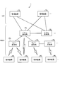
- FIG. 1 is a diagram illustrating a configuration example of a communication system 1 according to an embodiment of the present disclosure.
- the communication system 1 includes a management device 10, a donor base station 20, a relay base station 30, and a terminal device 40.
- the communication system 1 provides a user with a wireless network capable of mobile communication by operating the wireless communication devices configuring the communication system 1 in cooperation with each other.
- the wireless communication device is a device having a wireless communication function, and corresponds to the donor base station 20, the relay base station 30, and the terminal device 40 in the example of FIG. 1. In the following description, the wireless communication device may be simply referred to as a communication device.
- one or a plurality of devices included in the communication system 1 function as a communication control device that determines a route from the donor base station to the terminal device.
- the communication management device is the donor base station 20, but the communication control device is not limited to the donor base station 20.
- the communication management device may be the management device 10 or a device other than the management device 10 and the donor base station 20.
- the communication system 1 may include a plurality of management devices 10, donor base stations 20, relay base stations 30, and terminal devices 40, respectively.
- the communication system 1 includes management devices 10 1 , 10 2, etc. as the management device 10.
- the communication system 1 includes donor base stations 20 1 and 20 2 as the donor base station 20 and relay base stations 30 1 , 30 2 , and 30 3 as the relay base station 30.
- the communication system 1 includes terminal devices 40 1 , 40 2 , 40 3, 40 4, etc. as the terminal device 40.
- the management device 10 is a device that manages a wireless network.
- the management device 10 is a device that functions as an MME (Mobility Management Entity) or an AMF (Access and Mobility Management Function).
- the management device 10 constitutes a core network CN.
- the core network CN is, for example, EPC (Evolved Packet Core) or 5GC (5G Core network).
- the management device 10 is connected to each of the donor base stations 20.
- the management device 10 manages the communication of the donor base station 20.
- the management device 10 may manage the communication of the relay base station 30.
- the donor base station 20 is a base station that wirelessly communicates with the terminal device 40.
- the donor base station 20 can wirelessly communicate with the terminal device 40.
- the donor base station 20 may be configured to be able to wirelessly communicate with other donor base stations 20 and relay base stations 30.
- the donor base station 20 may be a ground base station device (ground station device) installed on the ground.
- the donor base station 20 may be a base station device arranged on a structure on the ground or a base station device installed on a moving body moving on the ground.
- the donor base station 20 may be an antenna installed in a structure such as a building and a signal processing device connected to the antenna.
- the donor base station 20 may be a structure or a moving body itself. “Ground” is not only the ground (terrestrial) but also the ground in a broad sense that includes ground, water, and water.
- the donor base station 20 is not limited to the ground base station.
- the donor base station 20 may be a non-ground base station (non-ground station) that can float in the air or space.
- the donor base station 20 may be an aircraft station device or a satellite station device.
- the aircraft station device is a wireless communication device that can float in the atmosphere, such as an aircraft.
- the aircraft station device may be a device mounted on an aircraft or the like, or may be the aircraft itself.
- the concept of an aircraft includes not only heavy aircraft such as airplanes and gliders, but also light aircraft such as balloons and airships.
- the concept of an aircraft includes not only heavy aircraft and light aircraft, but also rotorcraft such as helicopters and autogyros.
- the aircraft station device (or the aircraft on which the aircraft station device is mounted) may be an unmanned aircraft such as a drone.
- the concept of unmanned aerial vehicles includes unmanned aircraft systems (UAS) and tethered unmanned aerial vehicles systems (tethered UAS).
- unmanned aerial vehicles includes light unmanned aviation systems (LTA: Lighter than Air UAS) and heavy unmanned aviation systems (HTA: Heavier than Air UAS).
- LTA Lighter than Air UAS
- HTA Heavier than Air UAS
- HAPs High Altitude UAS Platforms
- Satellite device is a wireless communication device that can float outside the atmosphere.
- the satellite station device may be a device mounted on a space vehicle such as an artificial satellite, or may be the space vehicle itself.
- the satellite stations are low earth orbiting (LEO) satellites, medium earth orbiting (MEO) satellites, geostationary earth orbiting (GEO) satellites, and highly elliptical orbiting (HEO). It may be any satellite.
- the satellite station device may be a device mounted on a low-orbit satellite, a medium-orbit satellite, a geostationary satellite, or a high-elliptic orbit satellite.
- the donor base station 20 1 is connected to a relay base station 30.
- the donor base station 20 1 can indirectly wirelessly communicate with the terminal device 40 via the relay base station 30 1 .
- the donor base station 20 2 it is possible to indirectly communicate wirelessly with the terminal device 40 via the relay base station 30.
- the relay base station 30 is a device that serves as a relay station for the base station.
- the relay base station 30 is a kind of base station.
- the relay base station 30 can wirelessly communicate with the terminal device 40.
- the relay base station 30 relays communication between the donor base station 20 and the terminal device 40.
- the relay base station 30 may be configured to be able to wirelessly communicate with another relay base station 30 and the donor base station 20.
- the relay base station 30 functions as an MT (Mobile Termination) function with respect to the donor base station 20 or operates as a UE, and DU () with respect to another relay base station 30 (child relay base station). It may operate as a Distributed Unit).
- the relay base station 30 may be a ground station device or a non-ground station device.
- the relay base station 30 constitutes the radio access network RAN together with the donor base station 20.
- the terminal device 40 is, for example, a mobile phone, a smart device (smartphone or tablet), a PDA (Personal Digital Assistant), or a personal computer. Further, the terminal device 40 may be an M2M (Machine to Machine) device or an IoT (Internet of Things) device. Further, the terminal device 40 may be a wireless communication device installed in a mobile body or the mobile body itself. The terminal device 40 can wirelessly communicate with the donor base station 20 and the relay base station 30. The terminal device 40 may be capable of wireless communication, for example, D2D (Device to Device) communication, also in communication (side link) with another terminal device 40. Here, the D2D communication may be communication based on an interface called PC5.
- D2D Device to Device
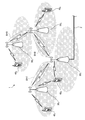
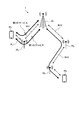
- FIG. 2 is a diagram for explaining IAB.
- the base station having the optical fiber F in the backhaul (donor base station 20 1 shown in FIG. 2) operates as the donor base station and other base stations (relay base stations 30 1 , 30 2 , 30). 3 ) to directly or indirectly provide wireless backhauls BH1 and BH2.
- the relay station 30 as a parent relay station provides a wireless backhaul BH3 to the relay base station 30 3. Note that the example of FIG.
- the donor base station 20 1 operates as a parent node (Parent node), and the relay base station 30 3 operates as a child node (Child node).
- the downlink (DL) of the wireless backhaul BH2 is DL Parent BH
- the uplink (UL) of the wireless backhaul BH2 is UL Parent BH
- the DL of the wireless backhaul BH3 is DL Child BH
- the UL of the wireless backhaul BH3 is UL Child BH. Call each one.
- the donor base station 20 can simultaneously provide an access line to any wireless communication device.
- the donor base station 20 may have a means for distinguishing between the relay base station and an arbitrary wireless communication device.
- Providing the backhaul line and the access line may include at least a process of allocating and scheduling Radio Resource, for example, Physical Resource Block (PRB).
- PRB Physical Resource Block
- the donor base station 20 1 provides backhaul lines BH1 and BH2 to the relay base stations 30 1 and 30 2 , and at the same time provides an access line to the terminal device 40 3 .
- the donor base station 20 may support time, frequency, and spatial multiplexing as a method of multiplexing the access line and the backhaul line.
- the relay base station 30 can provide an access line to an arbitrary wireless communication device at the same time as constructing the backhaul line BH1.
- the relay base station 30 may have a means for distinguishing the relay base station from an arbitrary wireless communication device.
- Providing a backhaul line and an access line may include at least a process of Radio Resource, for example, PRB allocation and scheduling.
- the relay base station 30 1 establishes a backhaul line with the donor base station 20 1 and, at the same time, provides an access line to the terminal device 40 1 .
- the relay base station 30 2 builds backhaul lines BH2 and BH3 with the donor base station 20 1 and the relay base station 30 3 and at the same time provides an access line to the terminal device 40 4 . Furthermore, the relay base station 30 3 builds a backhaul line BH3 with the relay base station 30 2 and at the same time provides an access line to the terminal device 40 2 .
- the relay base station 30 may support time, frequency, and spatial multiplexing as a method of multiplexing the access line and the backhaul line.
- the management device 10 is a device that manages a wireless network.
- the management device 10 is a device that manages the communication of the donor base station 20.
- the management device 10 may manage the communication of the relay base station 30.
- the management device 10 is, for example, a device having a function as an MME (Mobility Management Entity).
- the management device 10 is a device having a function as an AMF (Access and Mobility Management Function), for example.
- the management device 10 is not limited to a device having a function as an MME or AMF.
- some or all of the functions of the management device 10 may be integrated into a function called Central Unit (CU) in the concept of IAB.
- the function of this CU may be implemented in the donor base station 20.
- the management device 10 may have a gateway function.
- the management device 10 may have a function as an S-GW (Serving Gateway) or a P-GW (Packet Data Network Gateway).
- the management device 10 may have a function as a UPF (User Plane Function).
- the management device 10 does not necessarily have to be a device that constitutes the core network.
- the core network is a W-CDMA (Wideband Code Division Multiple Access) or cdma2000 (Code Division Multiple Access 2000) core network.
- the management device 10 may be a device that functions as an RNC (Radio Network Controller).
- RNC Radio Network Controller
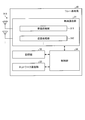
- FIG. 3 is a diagram illustrating a configuration example of the management device 10 according to the embodiment of the present disclosure.
- the management device 10 includes a communication unit 11, a storage unit 12, and a control unit 13.
- the configuration shown in FIG. 3 is a functional configuration, and the hardware configuration may be different from this.
- the functions of the management device 10 may be distributed and implemented in a plurality of physically separated configurations.
- the management device 10 may be composed of a plurality of server devices.
- the function of may be implemented as a CU in the donor base station.
- the communication unit 11 is a communication interface for communicating with other devices.
- the communication unit 11 may be a network interface or a device connection interface.
- the communication unit 11 may be a LAN (Local Area Network) interface such as a NIC (Network Interface Card), or a USB (Universal Serial Bus) host controller, a USB interface including a USB port, etc. Good.
- the communication unit 11 may be a wired interface or a wireless interface.
- the communication unit 11 functions as a communication unit of the management device 10.
- the communication unit 11 communicates with the donor base station 20 under the control of the control unit 13.
- the storage unit 12 is a storage device capable of reading and writing data such as DRAM (Dynamic Random Access Memory), SRAM (Static Random Access Memory), flash memory, and hard disk.
- the storage unit 12 functions as a storage unit of the management device 10.
- the storage unit 12 stores, for example, the connection state of the terminal device 40.
- the storage unit 12 stores the RRC (Radio Resource Control) state and the ECM (EPS Connection Management) state of the terminal device 40.
- the storage unit 12 may function as a home memory that stores the position information of the terminal device 40.
- the control unit 13 is a controller that controls each unit of the management device 10.
- the control unit 13 is realized by a processor such as a CPU (Central Processing Unit) and MPU (Micro Processing Unit).
- the control unit 13 is realized by the processor executing various programs stored in the storage device inside the management device 10 using a RAM (Random Access Memory) or the like as a work area.
- the control unit 13 may be realized by an integrated circuit such as an ASIC (Application Specific Integrated Circuit) or an FPGA (Field Programmable Gate Array).
- ASIC Application Specific Integrated Circuit
- FPGA Field Programmable Gate Array
- FIG. 4 is a diagram illustrating a configuration example of the donor base station 20 according to the embodiment of the present disclosure.
- the donor base station 20 can wirelessly communicate with the relay base station 30, the terminal device 40, and another donor base station 20. At this time, the wireless communication may be communication using millimeter waves.
- the donor base station 20 includes a wireless communication unit 21, a storage unit 22, and a control unit 23.
- the configuration shown in FIG. 4 is a functional configuration, and the hardware configuration may be different from this. Further, the function of the donor base station 20 may be distributed and implemented in a plurality of physically separated configurations.
- the wireless communication unit 21 is a wireless communication interface that wirelessly communicates with other wireless communication devices (for example, the terminal device 40 and the relay base station 30).
- the wireless communication unit 21 operates according to the control of the control unit 23.
- the wireless communication unit 21 supports one or more wireless access methods.
- the wireless communication unit 21 supports both NR and LTE.
- the wireless communication unit 21 may support W-CDMA and cdma2000 in addition to NR and LTE.
- the wireless communication unit 21 includes a reception processing unit 211, a transmission processing unit 212, and an antenna 213.
- the wireless communication unit 21 may include a plurality of reception processing units 211, transmission processing units 212, and antennas 213, respectively.
- each unit of the wireless communication unit 21 can be individually configured for each wireless access scheme.
- the reception processing unit 211 and the transmission processing unit 212 may be configured separately for LTE and NR.
- the reception processing unit 211 processes the uplink signal received via the antenna 213.
- the reception processing unit 211 includes a wireless reception unit 211a, a demultiplexing unit 211b, a demodulation unit 211c, and a decoding unit 211d.
- the radio reception unit 211a down-converts an uplink signal, removes unnecessary frequency components, controls an amplification level, orthogonal demodulation, converts into a digital signal, removes a guard interval, and removes a frequency domain signal by fast Fourier transform. Extract, etc.
- the demultiplexing unit 211b separates an uplink channel such as PUSCH (Physical Uplink Shared Channel) and PUCCH (Physical Uplink Control Channel) and an uplink reference signal from the signal output from the wireless reception unit 211a.
- PUSCH Physical Uplink Shared Channel
- PUCCH Physical Uplink Control Channel
- the demodulation unit 211c demodulates the received signal using a modulation method such as BPSK (Binary Phase Shift Keying) or QPSK (Quadrature Phase Shift Keying) for the modulation symbol of the uplink channel.
- the modulation method used by the demodulation unit 211c may be 16QAM (Quadrature Amplitude Modulation), 64QAM, or 256QAM.
- the decoding unit 211d performs a decoding process on the coded bits of the demodulated uplink channel.
- the decoded uplink data and uplink control information are output to the control unit 23.
- the transmission processing unit 212 performs transmission processing of downlink control information and downlink data.
- the transmission processing unit 212 includes an encoding unit 212a, a modulation unit 212b, a multiplexing unit 212c, and a wireless transmission unit 212d.
- the encoding unit 212a uses the downlink control information and downlink data input from the control unit 23 to perform block encoding, convolutional encoding, turbo encoding, LDPC (Low-Density Parity Check) encoding, polar encoding, etc. Encoding is performed using the encoding method of.
- the modulator 212b modulates the coded bits output from the encoder 212a by a predetermined modulation method such as BPSK, QPSK, 16QAM, 64QAM, 256QAM.
- the multiplexing unit 212c multiplexes the modulation symbol of each channel and the downlink reference signal, and arranges them in a predetermined resource element.
- the wireless transmission unit 212d performs various kinds of signal processing on the signal from the multiplexing unit 212c. For example, the wireless transmission unit 212d performs conversion into the time domain by fast Fourier transform, addition of a guard interval, generation of a baseband digital signal, conversion into an analog signal, quadrature modulation, up-conversion, removal of extra frequency components, Performs processing such as power amplification.
- the signal generated by the transmission processing unit 212 is transmitted from the antenna 213.
- the storage unit 22 is a data readable / writable storage device such as DRAM, SRAM, flash memory, and hard disk.
- the storage unit 22 functions as a storage unit of the donor base station 20.
- the control unit 23 is a controller that controls each unit of the donor base station 20.
- the control unit 23 is realized by a processor such as a CPU (Central Processing Unit) and MPU (Micro Processing Unit), for example.
- the control unit 23 is realized by the processor executing various programs stored in the storage device inside the donor base station 20 using a RAM (Random Access Memory) or the like as a work area.
- the control unit 23 may be realized by an integrated circuit such as an ASIC (Application Specific Integrated Circuit) or FPGA (Field Programmable Gate Array).
- ASIC Application Specific Integrated Circuit
- FPGA Field Programmable Gate Array
- the control unit 23 includes an acquisition unit 231, a determination unit 232, an instruction unit 233, a reception unit 234, and a transmission unit 235.
- Each block (acquisition unit 231 to transmission unit 235) forming the control unit 23 is a functional block showing the function of the control unit 23.
- These functional blocks may be software blocks or hardware blocks.
- each of the above functional blocks may be one software module realized by software (including a microprogram) or one circuit block on a semiconductor chip (die).
- each functional block may be one processor or one integrated circuit.
- the method of configuring the functional blocks is arbitrary.
- the control unit 23 may be configured in functional units different from the above functional blocks. The operation of each block (acquisition unit 231 to transmission unit 235) forming the control unit 23 will be described in detail in the description of a handover process and the like described later.
- FIG. 5 is a diagram illustrating a configuration example of the relay base station 30 according to the embodiment of the present disclosure.
- the relay base station 30 can wirelessly communicate with the terminal device 40. At this time, the wireless communication may be communication using millimeter waves.
- the relay base station 30 includes a wireless communication unit 31, a storage unit 32, a network communication unit 33, and a control unit 34. Note that the configuration shown in FIG. 5 is a functional configuration, and the hardware configuration may be different from this. Further, the function of the relay base station 30 may be distributed and implemented in a plurality of physically separated configurations.
- the wireless communication unit 31 is a wireless communication interface that wirelessly communicates with other wireless communication devices (for example, the donor base station 20 and the terminal device 40).
- the wireless communication unit 31 operates according to the control of the control unit 34.
- the wireless communication unit 31 includes a reception processing unit 311, a transmission processing unit 312, and an antenna 313.
- the configurations of the wireless communication unit 31, the reception processing unit 311, the transmission processing unit 312, and the antenna 313 are the same as those of the wireless communication unit 21, the reception processing unit 211, the transmission processing unit 212, and the antenna 213 of the donor base station 20.
- the storage unit 32 is a data readable / writable storage device such as DRAM, SRAM, flash memory, and hard disk.
- the storage unit 32 functions as a storage unit of the relay base station 30.
- the configuration of the storage unit 32 is similar to that of the storage unit 22 of the donor base station 20.
- the network communication unit 33 is a communication interface for communicating with other devices.
- the network communication unit 33 is a LAN interface such as NIC.
- the network communication unit 33 may be a wired interface or a wireless interface.
- the network communication unit 33 functions as a network communication unit of the relay base station 30.
- the network communication unit 33 communicates with the donor base station 20 under the control of the control unit 34.
- the control unit 34 is a controller that controls each unit of the relay base station 30.
- the control unit 34 has the same configuration as the control unit 23 of the donor base station 20.
- FIG. 6 is a diagram illustrating a configuration example of the terminal device 40 according to the embodiment of the present disclosure.
- the terminal device 40 can wirelessly communicate with the donor base station 20 and the relay base station 30. At this time, the wireless communication may be communication using millimeter waves.
- the terminal device 40 includes a wireless communication unit 41, a storage unit 42, a network communication unit 43, an input / output unit 44, and a control unit 45.
- the configuration shown in FIG. 6 is a functional configuration, and the hardware configuration may be different from this. Further, the functions of the terminal device 40 may be distributed and implemented in a plurality of physically separated configurations.
- the wireless communication unit 41 is a wireless communication interface that wirelessly communicates with other wireless communication devices (for example, the donor base station 20 and the relay base station 30).
- the wireless communication unit 41 operates under the control of the control unit 45.
- the wireless communication unit 41 supports one or more wireless access methods.
- the wireless communication unit 41 supports both NR and LTE.
- the wireless communication unit 41 may support W-CDMA or cdma2000 in addition to NR and LTE.
- the wireless communication unit 41 includes a reception processing unit 411, a transmission processing unit 412, and an antenna 413.
- the wireless communication unit 41 may include a plurality of reception processing units 411, transmission processing units 412, and antennas 413, respectively.
- each unit of the wireless communication unit 41 can be individually configured for each wireless access scheme.
- the reception processing unit 411 and the transmission processing unit 412 may be configured separately for LTE and NR.
- the reception processing unit 411 processes the downlink signal received via the antenna 413.
- the reception processing unit 411 includes a wireless reception unit 411a, a demultiplexing unit 411b, a demodulation unit 411c, and a decoding unit 411d.
- the wireless reception unit 411a down-converts a downlink signal, removes unnecessary frequency components, controls amplification level, orthogonal demodulation, converts to a digital signal, removes a guard interval, and removes a frequency domain signal by fast Fourier transform. Extract, etc.
- the demultiplexing unit 411b separates the downlink channel, the downlink synchronization signal, and the downlink reference signal from the signal output from the wireless reception unit 411a.
- the downlink channel is, for example, a channel such as PBCH (Physical Broadcast Channel), PDSCH (Physical Downlink Shared Channel), and PDCCH (Physical Downlink Control Channel).
- PBCH Physical Broadcast Channel
- PDSCH Physical Downlink Shared Channel
- PDCCH Physical Downlink Control Channel
- the demodulation unit 211c demodulates the received signal to the downlink channel modulation symbol by using a modulation method such as BPSK, QPSK, 16QAM, 64QAM, 256QAM.
- the decoding unit 411d performs a decoding process on the demodulated coded bits of the downlink channel.
- the decoded downlink data and downlink control information are output to the control unit 23.
- the transmission processing unit 412 performs transmission processing of uplink control information and uplink data.
- the transmission processing unit 412 includes an encoding unit 412a, a modulation unit 412b, a multiplexing unit 412c, and a wireless transmission unit 412d.
- the coding unit 412a performs block coding, convolutional coding, turbo coding, LDPC (Low-Density Parity Check) coding, polar coding, etc. on the uplink control information and uplink data input from the control unit 45. Encoding is performed using the encoding method of.
- the modulator 412b modulates the coded bits output from the encoder 412a by a predetermined modulation method such as BPSK, QPSK, 16QAM, 64QAM, 256QAM.
- the multiplexing unit 412c multiplexes the modulation symbol of each channel and the uplink reference signal, and arranges them in a predetermined resource element.
- the wireless transmission unit 412d performs various kinds of signal processing on the signal from the multiplexing unit 412c. For example, the wireless transmission unit 412d performs conversion into the time domain by inverse fast Fourier transform, addition of a guard interval, generation of a baseband digital signal, conversion into an analog signal, quadrature modulation, up-conversion, removal of extra frequency components. , Processing such as power amplification.
- the signal generated by the transmission processing unit 412 is transmitted from the antenna 413.
- the storage unit 42 is a data readable / writable storage device such as DRAM, SRAM, flash memory, and hard disk.
- the storage unit 42 functions as a storage unit of the terminal device 40.
- the network communication unit 43 is a communication interface for communicating with other devices.
- the network communication unit 43 is a LAN interface such as NIC.
- the network communication unit 43 may be a wired interface or a wireless interface.
- the network communication unit 43 functions as a network communication unit of the terminal device 40.
- the network communication unit 43 communicates with other devices under the control of the control unit 45.
- the input / output unit 44 is a user interface for exchanging information with the user.
- the input / output unit 44 is an operation device such as a keyboard, a mouse, operation keys, and a touch panel for the user to perform various operations.
- the input / output unit 44 is a display device such as a liquid crystal display (Liquid Crystal Display) or an organic EL display (Organic Electroluminescence Display).
- the input / output unit 44 may be an audio device such as a speaker or a buzzer.
- the input / output unit 44 may be a lighting device such as an LED (Light Emitting Diode) lamp.
- the input / output unit 44 functions as an input / output unit (input unit, output unit, operation unit or notification unit) of the terminal device 40.
- the control unit 45 is a controller that controls each unit of the terminal device 40.
- the control unit 45 is realized by a processor such as a CPU or MPU, for example.
- the control unit 45 is realized by the processor executing various programs stored in the storage device inside the terminal device 40 using the RAM or the like as a work area.
- the control unit 45 may be realized by an integrated circuit such as ASIC or FPGA.
- the CPU, MPU, ASIC, and FPGA can all be regarded as controllers.
- the control unit 45 includes an acquisition unit 451, an identification unit 452, a switching unit 453, a reception unit 454, and a transmission unit 455.
- Each block (acquisition unit 451 to transmission unit 455) forming the control unit 45 is a functional block showing the function of the control unit 45.
- These functional blocks may be software blocks or hardware blocks.
- each of the above functional blocks may be one software module realized by software (including a microprogram) or one circuit block on a semiconductor chip (die).
- each functional block may be one processor or one integrated circuit.
- the method of configuring the functional blocks is arbitrary.
- the control unit 45 may be configured in functional units different from the above functional blocks. The operation of each block (acquisition unit 451 to transmission unit 455) included in the control unit 45 will be described in detail in the description of connection processing, handover processing, and the like described later.
- Example of route selection >> Next, an example of selecting a route between the donor base station 20 and the terminal device 40 will be described.
- FIG. 7 is a diagram showing an example of route selection between the donor base station 20 and the terminal device 40. Specifically, it is a diagram showing an example of route selection with respect to two terminal devices, a terminal device 40 1 and a terminal device 40 2 .
- the terminal device 40 1 is communicating via the access line of the relay base station 30 1 .
- the relay base station 30 1 has a backhaul line BH1 with the donor base station 20 1 .
- the terminal device 40 2 is communicating via the access line of the relay base station 30 3 .
- the relay station 30 3 has a backhaul line BH3 between the relay station 30 2, further, the relay base station 30 2 has a backhaul line BH2 between the donor base station 20 1 ing.
- the relay base station 30 1 has a 1-hop backhaul line
- the relay base station 30 3 has a 2-hop backhaul line.
- the IAB backhaul line is expected to utilize millimeter waves and beamforming to exchange large amounts of data.
- mobile IAB relay stations will be discussed in the future, at the beginning of the introduction, most of the IAB relay stations are fixedly installed, and it is thought that beamforming is relatively easy to apply.
- millimeter waves there is a concern that communication quality will frequently deteriorate due to external factors such as blocking caused by a moving object or the like. Therefore, it is considered important to have a mechanism to quickly select and switch the optimal route.
- FIG. 8A is a diagram showing an example of route selection when the communication quality of a part of the backhaul lines shown in FIG. 7 deteriorates.
- the relay base station 30 1 establishes a backhaul line BH4 with the relay base station 30 3 .
- the terminal device 40 1 can connect to the donor base station 20 1 via the 3-hop backhaul line of BH2, BH3, and BH4 while maintaining the access line of the relay base station 30 1 .
- the terminal device 40 1 can also give up the access line of the relay base station 30 1 and build an access line with the donor base station 20 1 .
- FIG. 8B is a diagram showing another example of route selection when the communication quality of a part of the backhaul lines shown in FIG. 7 deteriorates.
- the terminal device 40 1 can determine whether to maintain the connection with the relay base station 30 1 or to establish a new connection with the donor base station 20 1 .
- the terminal device 40 1 cannot determine to construct a new backhaul line between the relay base station 30 1 and the relay base station 30 3 as in the case of FIG. 8A, at least the network side, for example, it may be necessary to donor base station 20 1 is involved in the selection of the optimal path.
- a node called CU Central Unit
- the CU can be restated as a communication control device.
- the relay base station 30 1 when the relay base station 30 1 detects Radio Link Failure (RLF) for BH1, it instructs the terminal device 40 1 to perform Connection Release. Further, when the relay base station 30 2 detects the RLF regarding BH2, the relay base station 30 2 instructs the relay base station 30 3 and the terminal device 40 2 to perform Connection Release.
- RLF Radio Link Failure
- the relay base station 30 2 if the relay station 30 3 is providing access line to a plurality of terminal devices 40, Broadcast, or in Groupcast manner, via the relay base station 30 2 The connection release may be instructed simultaneously to a plurality of terminal devices 40 using the route.
- the relay base stations that have lost all the backhaul lines execute Admission Control until the backhaul lines are reconstructed. Good. That is, the relay base stations 30 1 , 30 2, and 30 3 reject the connection request from the terminal device 40 or a different relay base station during this period. Also, the relay base stations 30 1 , 30 2, and 30 3 notify the information including the Access Class Barring set via the system information as the Access Control information during this period, so that the terminal device 40 or different You may make it suppress the connection request from a relay base station. Note that an internal timer period may be set as the period until the backhaul line is reconfigured, and the timer may be activated when the RLF is detected.
- Connection Release may be instructed after the timer expires.
- the parameter of the Access Class Barring may be set based on the period of the timer. Then, the terminal device 40 that has executed the Connection Release newly identifies the base station that supports the desired network slice and executes the connection process by the method described below.
- the CU may be arranged in the donor base station 20 or may be mounted in any device in the core network.
- the CU may be the control unit 23 included in the donor base station 20 or the control unit 13 included in the management device 10. If the donor base station 20 and the management device 10 are composed of a plurality of devices, one or more of them may function as a CU. It is also possible to give the relay base station 30 and the terminal device 40 a function as a CU.
- Example of route selection according to service used by terminal device> In 5G, the key is to realize the concept of network slicing. That is, it is assumed that the terminal device 40 appropriately receives communication services having different characteristics such as high throughput or low delay. For example, the terminal apparatus 40 1, when receiving the service that requires low delay and high path hop count as in the example of FIG. 8A has been selected, it may not meet the requirements of low delay . That is, the CU is desired to select an optimum route according to the service used by the terminal device 40. In this case, it is desired that the CU activates the measurement report and the handover regarding the backhaul line prior to the construction of the optimum route.
- the service type may be determined based on the identification information of the network slice, for example, slice ID (Slice ID).
- slice ID Slice ID
- the terminal apparatus 40 1 services requiring low latency, e.g., when undergoing URLLC (Ultra-Reliable Low Latency Communication ) is CU, in response to the slice ID corresponding to the low-latency services, FIG. A route via a backhaul line having a small number of hops such as 8B may be selected.
- the terminal device 40 services requiring a high throughput, for example, when undergoing eMBB (enhanced Mobile Broadband), the CU, in response to the slice ID corresponding to the high-throughput, for example, in FIG. 8B Thus, a route including a base station close to the terminal device 40 1 may be selected.
- CU monitors the load on each relay station 30 switches the path dynamically selects the route via the relay station 30 with less impact Good.
- CU when the terminal apparatus 40 1 is receiving a mMTC (massive Machine Type Communication), because it is not sensitive with respect to delay, CU, for example, as the traffic of each MTC is distributed, assigned to another MTC
- the backhaul line may be selected in consideration of the route used.
- LPWA Low Power Wide Area
- the slice ID may be, for example, S-NSSAI (Single Network Slice Selection Assistance Information).
- S-NSSAI is composed of SST (Slice / Service type).
- the S-NSSAI may be composed of SST and SD (Slice Differentiator).
- the service type may be determined based on other preset criteria than the slice ID.
- the slice ID can be regarded as information indicating a communication mode of a communication service received by the terminal device 40 using the wireless network of the communication system 1 (for example, whether the communication service received by the terminal device 40 is URLLC, eMBB, or mMTC).
- the service type may be determined based on the capability of the terminal device 40 (for example, UE Capability).
- FIG. 9A is a diagram showing a route selection example in which the terminal device 40 1 receives a plurality of services simultaneously. In the example of FIG. 9A, the terminal device 40 1 simultaneously receives two services (first service and second service) having different slice IDs.
- the CU When the quality of the backhaul line BH1 deteriorates, the CU gives an instruction to construct a backhaul line between the relay base station 30 1 and the relay base station 30 3 as shown in the example of FIG. 8A or 8B. .
- the CU specifies, for each slice ID, an optimal path of data exchanged between the donor base station 20 1 and the terminal device 40 1 .
- FIG. 9B is a diagram showing an example of route selection when the communication quality of a part of the backhaul lines shown in FIG. 9A deteriorates.
- the communication quality of the backhaul line BH1 that connects the relay base station 30 1 and the donor base station 20 1 has deteriorated.
- the CU specifies a route including a base station adjacent to the terminal device 40 1 as shown in FIG. 9B for the first service. In this case, the access line used by the terminal device 40 1 remains unchanged as the access line AL1, and thus the connection with the relay base station 30 1 is maintained.
- the CU specifies a route via the backhaul line having a small number of hops as shown in FIG. 9B for the second service. Therefore, CU, for example, to the terminal apparatus 40 1, so as to utilize the access line AL2 donor base station 20 1 instructs the handover to the donor base station 20 1.
- the slice ID regardless of the quality of the terminal device 40 first access line, the trigger degradation of the quality of the backhaul, the handover of the terminal device 40 1 can be started.
- the terminal apparatus 40 1 is reported differently whether information has the ability to connect the relay station 30, for example, the number of transceivers from the terminal device 40 1 at the same time There is a need. For example, to provide information about this capability (eg, UE Capability) as part of the NSSAI (Network Slice Selection Assistance Information) via any message (eg, Message 3) sent to the CU in the initial access process.
- UE Capability information about this capability
- NSSAI Network Slice Selection Assistance Information
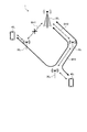
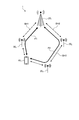
- FIG. 10 is a diagram illustrating an example of a connection state between the terminal device 40 1 and the donor base station 20 1 .
- the terminal device 40 1 is connected to the donor base station 20 1 via a route P1 via the backhaul line BH1.
- the backhaul line BH1 is a line connecting the relay base station 30 1 and the donor base station 20 1 .
- the route P2 illustrated in FIG. 10 is a route connecting the terminal device 40 1 and the donor base station 20 1 via the backhaul lines BH2 and BH3.
- the backhaul line BH2 is a line connecting the relay base station 30 2 and the donor base station 20 1
- the backhaul line BH3 is a line connecting the relay base station 30 3 and the relay base station 30 2. Is.
- CU is assumed to be a donor base station 20 1
- CU may be another device included in the communication system 1.
- the donor base station 20 1 of the following description (or, according to the donor base station 20) is replaced by another appropriate device.
- the service received by the terminal device 40 includes a plurality of communication services having different communication modes.
- the plurality of communication services include at least two communication services selected from mMTC, eMBB, and URLLC.
- the plurality of communication services may include communication services other than mMTC, eMBB, and URLLC.
- the terminal device 40 can simultaneously receive at least two communication services.
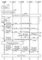
- FIG. 11 is a diagram illustrating an example of a connection process when there is no network slice information from a neighboring base station. Specifically, it is a diagram showing an example of a connection process in the case where information regarding a network slice is not provided from a neighboring base station via system information, or the neighboring base station does not support a desired network slice. .
- the terminal apparatus 40 1 is connected to the donor base station 20 1 in the route P1 shown in FIG. 10, and those that are not connected to the donor base station 20 1, the path P2.
- the terminal device 40 First, the terminal device 40 1, cell selection, or performing cell reselection process (step S101). Then, based on the processing result, the terminal device 40 1 executes the random access procedure (Random Access Procedure) for the relay base station 30 1 which is the highest ranked cell (step S102). Then, the terminal device 40 1 establishes an RRC connection (Radio Resource Control Connection) with the donor base station 20 1 via the access line of the relay base station 30 1 (step S103).
- RRC connection Radio Resource Control Connection
- an SRB Signaling Radio Bearer
- C-plane a control signal of a control plane
- the terminal device 40 1 can be any message of the random access processing (e.g., Message 3), or any message of RRC connection setup process (RRC Connection Setup Procedure) (e.g., RRC Connection Request, RRC Connection Setup Complete ) Can be used to notify the information about the service that the terminal device 40 1 receives.
- RRC Connection Setup Procedure e.g., RRC Connection Request, RRC Connection Setup Complete
- the terminal device 40 1 can notify the donor base station 20 1 of the desired slice ID using an arbitrary message of the RRC connection setup process.
- the slice ID may be, for example, S-NSSAI as described above.
- the acquisition unit 231 of the donor base station 20 1 acquires information about the service received by the terminal device 40 1 (for example, information on a slice ID desired by the terminal device 40 1 ).
- the route P1 set in the RRC connection establishment procedure with the donor base station 20 1 via the access line of the relay base station 30 1 can be considered as a default route.
- the terminal device 40 1 performs an attach process (Attach Procedure) (step S104).
- Attach Procedure user plane between the donor base station 20 1 (hereinafter, also referred to as U-plane.) DRB for transmitting and receiving data (Data Radio Bearer) are established.
- the CU sets a retransmission processing automatic repeat request (ARQ) method (for example, Hop by Hop or End to End) according to the slice ID.
- ARQ retransmission processing automatic repeat request
- an End to End ARQ process with a small delay that is, a method of controlling the ARQ process between a relay base station providing an access line and a donor base station 20 is provided. Is set. Further, in the case of a service that requires high throughput, for example, eMBB, a Hop by Hop ARQ process with good utilization efficiency of radio resources, that is, a method of controlling the ARQ process for each backhaul line is set.
- Hybrid ARQ processing is set between the terminal device 40 and the relay base station that provides the access line.
- Determination unit 232 of the donor base station 20 determines a path through the data to be exchanged between the terminal device 40 1 and the donor base station 20 1. For example, determination unit 232, together with the terminal apparatus 40 1 to identify the slice ID of desired, to identify the optimal route for providing network slice corresponding to the specified slice ID (T1 shown in FIG. 11).
- the instruction unit 233 of the donor base station 20 1 instructs the terminal device 40 1 to connect the donor base station 20 or the relay base station 30 based on the specified route. For example, the instruction unit 233 sets the terminal device 40 1 to execute the measurement report process including the relay base station 30 (for example, the relay base station 30 3 ) included in the specified route as the measurement target. This instruction is set, for example, via a connection reconfiguration message (steps S105a and S105b).
- the terminal device 40 1 When the setting is completed, the terminal device 40 1 returns a connection reconfiguration complete message to the donor base station 20 1 via the relay base station 30 1 (steps S106a and S106b). On the other hand, if the donor base station 20 1 can not determine the optimal route for providing a network slice corresponding to the desired slice ID returns a message refuse to provide the desired slice ID.
- the terminal device 40 1 performs the measurement including the relay base station 30 3 as the measurement target based on the set measurement report process (T2 shown in FIG. 11). Then, the terminal device 40 1 reports the measurement result to the donor base station 20 1 via the relay base station 30 1 (steps S107a and S107b).
- the instruction unit 233 of the donor base station 20 1 is specified to the terminal device 40 1 based on the route determined by the determination unit 232.
- the base station to be handed over For example, assume a case where the relay base station 30 that provides a network slice corresponding to a desired slice ID is the relay base station 30 3 .
- the instruction unit 233 based on the measurement results reported from the terminal device 40 1, to the terminal device 40 1 determines handover to the relay station 30 3.
- Various known standards can be adopted as the criterion for determining whether or not to execute the handover.
- the instruction unit 233 issues a slice base handover request (Slice based HO Request) to the relay base station 30 3 (step S108a, S108b).
- the donor base station 20 1 When the relay base station 30 3 responds to the donor base station 20 1 with a positive response (Slice based HO Request ACK) to the slice-based handover request (steps S109a and S109b), the donor base station 20 1 informs the terminal device 40 1. Then, a message (Slice based Connection Reconfiguration message) instructing the handover to the relay base station 30 3 is transmitted to the relay base station 30 1 (steps S110a and S110b).
- a message (Slice based Connection Reconfiguration message) instructing the handover to the relay base station 30 3 is transmitted to the relay base station 30 1 (steps S110a and S110b).
- the terminal device 40 1 Upon receiving the message, the terminal device 40 1 executes a random access process on the relay base station 30 3 (step S111). When the handover to the relay base station 30 3 is completed, the terminal device 40 1 transmits a slice-based connection reconfiguration complete message to the donor base station 20 1 (steps S112a and S112b). , S112c, S112d). As a result, the optimum path P2 that provides the network slice corresponding to the slice ID is set. That is, according to the conventional mobility management method, after the terminal device 401 establishes a default route based on cell selection or cell reselection processing, prior to transmission / reception of data via the network slice corresponding to the desired slice ID. Switching to the optimal route is performed.
- step S113 transmission / reception of data via the network slice corresponding to the desired slice ID is started (step S113). Transmission and reception of data, the donor base station 20 1 of the receiving unit 234, transmitting unit 235, the terminal device 40 1 of the receiving unit 454, performed by the transmitting unit 455.
- the terminal device 40 1 may utilize multiple network slices simultaneously, for each network slice can be performed independently the process shown in FIG. 11. That is, a plurality of radio bearers corresponding to each network slice can be simultaneously constructed. If the terminal device 40 1 has the ability to connect to a plurality of base stations at the same time, the terminal device 40 1 must simultaneously establish a radio bearer corresponding to each network slice with a plurality of base stations. You can also
- step S104 for establishing the DRB for transmitting / receiving the U-plane data is performed after the handover to the relay base station 30 3 providing the network slice corresponding to the desired slice ID is completed. It may be performed for the relay base station 30 3 .
- the terminal device 40 1 maintains the default route via the access line of the relay base station 30 1 as an SRB for transmitting and receiving a control signal of the C-plane, as one form of C / U-plane separation.
- a path including the relay base station 30 3 for the DRB that transmits / receives the U-plane data of the network slice corresponding to the desired slice ID may be established separately from the SRB.
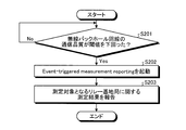
- FIG. 12 is a flowchart showing an example of the backhaul line quality monitoring process. The processing illustrated in FIG. 12 is executed by each of the plurality of relay base stations 30 included in the communication system 1, for example. The backhaul line quality monitoring process will be described below with reference to the flowchart of FIG.
- the relay base station 30 measures the quality of the wireless backhaul line with the parent relay base station 30 (or the donor base station 20 1 ) at a fixed cycle or a variable cycle and sets a threshold value. It is determined whether or not it is below (step S201).
- the measurement frequency, period, and threshold are set by control information (for example, RRC connection reconfiguration or RRC connection release).
- the quality of the backhaul line may be evaluated based on the reception strength or reception quality of the reference signal or the synchronization signal, that is, RSRP (Reference Signal Received Power) or RSRQ (Reference Signal Received Quality).
- RSRP Reference Signal Received Power
- RSRQ Reference Signal Received Quality
- the relay base station 30 activates the event triggered measurement result reporting process (Event Triggered measurement reporting) process (step S202).
- the relay station 30 in addition to the wireless backhaul link quality between a parent relay station, and reports the measurement results regarding the quality of the relay station 30 of the parent candidate to be measured to the donor base station 20 1 (step S203).
- each relay base station 30 of the parent candidate to be measured is set by, for example, the above-mentioned RRC connection resetting or RRC connection release.
- the donor base station 20 1 may set the report on the load for each relay station 30.
- the donor base station 20 1 may be set to report when the amount of traffic transmitted and received per unit time exceeds a threshold value.
- the amount of traffic transmitted / received per unit time may be a PRB usage indicating the ratio of used PRBs among all PRBs (Physical Resource Blocks) per unit frequency / unit time.
- the report on the load may be set in a unit called a flow or in a bearer unit.
- the donor base station 20 1, bearer or for each slice ID it is possible to determine the switching of the backhaul.
- the donor base station 20 1, the quality of the backhaul for each relay station, or, on the basis of the report on the load of the relay station, flow control, i.e., the scheduling of data to be transferred to the child relay station May be controlled. This scheduling may be performed for each QoS or slice ID.
- the donor base station 201 executes the Admission Control or the Access Control to the child relay base stations based on the quality of the backhaul line of each relay base station or the report on the load of each relay base station. Good.
- the Access Control broadcasts the Access Control information including the Access Class Barring set via the system information, for example.
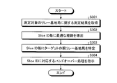
- FIG. 13 is a flowchart showing an example of a backhaul line handover process.
- the process shown in FIG. 13 is executed by the CU (for example, the donor base station 20).
- the donor base station 20 1 executes the following handover process, but the CU that executes the following handover process is not limited to the donor base station 20 1 .
- the relay base station 30 is a type of communication device.
- the handover process of the backhaul line will be described with reference to the flowchart of FIG.
- the measurement results regarding the quality of the relay station 30 to be measured is received from the relay station 30 which starts the event triggered measurement report process (step S301).
- the relay base station 30 that has activated the event activation measurement result report processing is referred to as the relay base station 30 that is the handover processing target.
- the acquisition unit 231 to the donor base station 20 1 from the relay base station 30, terminal device 40 in the communication system 1 The information on the service received using the wireless network (for example, the slice ID of the slice used by the terminal device 40) may be acquired. If the terminal device 40 receives a plurality of communication services, the acquisition unit 231 may acquire information on a plurality of communication services (for example, information on a plurality of slice IDs).
- the determination unit 232 of the donor base station 20 1, based on the information about the service, to determine a path through data exchanged is between the terminal device 40 1 and the donor base station 20 1. For example, the determination unit 232 derives an optimal path for each slice ID (step S302).
- the donor base station 20 1 based on the information of the optimum path, the relay station 30 handover processed to identify the base station to be the target of handover (step S303).
- the relay base station 30 that is the target of the handover process is the relay base station 30 1 shown in FIG. 9A.
- the donor base station 20 1 relays the donor base station 20 1 relays as shown in FIG. 9B.
- the base station 30 1 specifies the base station to be the target of the handover as the relay base station 30 3 .
- the base station that is the target of the handover (hereinafter referred to as the target base station) is not limited to the relay base station 30 and may be the donor base station 20.
- the instruction unit 233 to the donor base station 20 1, to the relay station 30 handover processing target, and instructs the handover process (step S304).
- the instruction unit 233 may instruct the handover for each slice ID.
- the relay base station 30 that is the target of the handover process may be instructed to perform a plurality of handovers corresponding to the slice IDs.
- the relay base station 30 establishes a plurality of connections with different target base stations.
- the slice ID e.g., Hop By Hop, or, End-to End
- the master relay base station of each backhaul line included in the route may be instructed to reset the ARQ process, or the handover is performed. Only the parent relay base station of the established backhaul line may be instructed to reset the ARQ process. Even when the ARQ process resetting is instructed only to the parent relay base station of the backhaul line for which the handover is executed, the transfer process or the parent relay base station of the other backhaul line is performed or , ARQ process reset may be instructed. On the other hand, when the End-to-End ARQ process is reset, the parent relay base station of each backhaul line may be instructed to reset the transfer process. Further, the relay base station that provides the access line may be instructed to reset the transfer process or the Hybrid ARQ process.
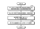
- FIG. 14 is a flowchart showing an example of handover processing of an access line.
- the process shown in FIG. 14 is executed by the CU (for example, the donor base station 20).
- the donor base station 20 1 executes the following handover process, but the CU that executes the following handover process is not limited to the donor base station 20 1 .
- the terminal device 40 is a type of communication device.
- the access line handover process will be described with reference to the flowchart of FIG.
- the acquisition unit 231 to the donor base station 20 1 the measurement results regarding the quality of the relay station 30 to be measured is acquired from the relay base station 30 which starts the event triggered measurement report process (step S401). Subsequently, the determination unit 232 of the donor base station 20 1 derives the optimum path for each slice ID (step S402). Then, the determination unit 232 specifies the relay base station 30 that provides the access line to the terminal device 40 for each slice ID based on the information of the optimum route (step S403).
- the instruction unit 233 to the donor base station 20 determines whether there is a change in the relay station 30 to provide access line to the terminal device 40 (step S404). For a slice ID that changes, the instruction unit 233 instructs the terminal device 40 using the service corresponding to the slice ID to perform the handover process (step S405). Further, the instruction unit 233 of the donor base station 201 resets the ARQ process corresponding to the slice ID.
- the parent relay base station of each backhaul line included in the route may be instructed to reconfigure the ARQ process or the influence of the route switching. Only the parent relay base station of the backhaul line that has received the instruction may be instructed to reset the ARQ process.
- the transfer process to the parent relay base station of the other backhaul line may be instructed to reset the ARQ process.
- the parent relay base station of each backhaul line may be instructed to reset the transfer process.
- Hybrid ARQ processing is set between the relay base station providing the access line and the terminal device 40.
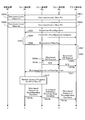
- 15A and 15B are diagrams illustrating an example of a signaling flow related to optimum path selection corresponding to a slice ID. The following description will be made assuming that the terminal device 40 1 and the donor base station 20 1 are in the connection state shown in FIG. 9A.
- both the first service (slice ID # 1) and the second service (slice ID # 2) are connected to the terminal device 40 1 via the access line AL1 and the backhaul line BH1. and transmission and reception of data between the donor base station 20 1 has been performed (step of FIG. 15A S501a, S501b, S502a, S502b ).
- the access line AL1 is a line between the terminal device 40 1 and the relay base station 30 1 .
- the backhaul line BH1 is a line between the relay base station 30 1 and the donor base station 20 1 .
- the donor base station 20 1 sends control information (for example, a Connection Reconfiguration message).
- control information for example, a Connection Reconfiguration message
- the measurement and its reporting method are set in the relay base station 30 1 via (step S503).
- the relay base station 30 1 transmits control information (for example, Connection Reconfiguration Complete message) to the donor base station 20 1 (step S504).
- the relay base station 30 1 starts monitoring the quality of the backhaul line between the donor base stations 20 1 based on the setting, and when the quality becomes equal to or lower than the threshold value, starts measuring the relay base station 30 that is the measurement target (Ste S505).
- the relay base station 30 to be measured is the relay base station 30 and the donor base station 20 1 that are the target base stations of the handover.
- the relay base station 30 1 activates the event triggered measurement result reporting process based on the set condition, and the current parent relay base station (or the donor base station 20 1 ) and the measurement target are measured. reporting the results measurements of the containing quality of relay station 30 to the donor base station 20 1 (step S506).
- Determination unit 232 of the donor base station 20 based on the information about the service to which the terminal device 40 1 receives via the communication system 1, through which data is exchanged between the terminal device 40 1 and the donor base station 20 1 Determine the route to take. For example, determination unit 232, the received measurement results, and, based on the slice ID corresponding to the service to the terminal apparatus 40 1 is utilized to derive an optimal route (step S507).
- the service which the terminal device 40 1 is utilized may be a plurality of service as shown in the example of FIG. 9A.
- the donor base station 20 1 identifies the slice ID needed to establish a new backhaul line (step S508).
- the instruction unit 233 of the donor base station 20 1 transmits a handover request, for example, a slice-based handover request (Slice based HO Request) to the relay base station 30 3 that is a target base station for handover regarding the specified slice ID. (Steps S509a and S509b).
- Relay station 30 3 which has finished the necessary preparations handover, response to the request of the handover, for example, returns slice base handover request acknowledgment (Slice based HO Request ACK) to the donor base station 20 1 (step S510a , S510b).
- the instruction unit 233 of the donor base station 20 1 instructs the relay base station 30 1 to perform a handover instruction including information on a slice ID for which handover of the backhaul line is necessary, for example, slice base.
- a connection reconfiguration (Slice based Connection Reconfiguration) is transmitted (step S511).
- the relay base station 30 1 Upon receiving the handover instruction, the relay base station 30 1 performs random access to switch the connection of the backhaul line for the first service (slice ID # 1) from the donor base station 20 1 to the relay base station 30 3. A process (Random Access Procedure) is executed (step S512).
- a relay base station 30 Upon completion of the switching of the connection of the backhaul line for a particular slice ID, a relay base station 30 1, the response to an instruction of the handover (e.g., a slice base connection reconfiguration complete (Slice based Connection Reconfiguration Complete)) the donor base station 20 1 to reply (step S513a, S513b, S513c), hand-over of the necessary backhaul line is completed.
- an instruction of the handover e.g., a slice base connection reconfiguration complete (Slice based Connection Reconfiguration Complete)
- the donor base station 20 1 notifies the relay base station 30 or the update of information for controlling the routing in the donor base station 20 1 (steps S514a, S514b, and S514c in FIG. 15B).
- the information for controlling the routing is, for example, information about the change of the routing table according to the slice ID, the bearer mapping according to the slice ID, or the control of the QoS flow mapping.
- the bearer mapping according to the slice ID may be information for identifying the route determined according to the slice ID, for example, bearer mapping according to the route ID.
- the QoS flow mapping according to the slice ID may be information for identifying the route determined according to the slice ID, for example, the QoS flow mapping according to the route ID.
- the relay base station 30 1 that provides the access line to the terminal device 40 1 uses the slice base connection resetting (step S511) received from the donor base station 20 1 to determine the terminal device 40 1 according to the slice ID. There set the measurement method and reporting method is required to switch the access line to the terminal apparatus 40 1 (step S515). At this time, the relay base station 30 1 may set the measurement method and the reporting method in the terminal device 40 1 via the control information (for example, slice-based connection resetting).
- the terminal device 40 1 measures the relay base station 30 or the donor base station 20 1 to be measured according to the slice ID based on the setting (T3 in FIG. 15B). Then, the terminal device 40 1 reports the measurement result to the donor base station 20 1 (steps S516a, S516b, S516c, S516d).
- the terminal device 40 1 that has received the handover instruction performs a random access process in order to switch the connection of the access line for the second service (slice ID # 2) from the relay base station 30 1 to the donor base station 20 1. Execute (step S518). Upon completion of the switching of the connection of the access line to a particular slice ID, the terminal device 40 1, the response to an instruction of the handover, for example, slice base connection reconfiguration complete (Slice based Connection Reconfiguration Complete) to the donor base station 20 1 A reply is sent (step S519), and the necessary access line handover is completed.
- slice base connection reconfiguration complete Slice based Connection Reconfiguration Complete
- the data related to the first service is transmitted / received via the access line AL1 and the backhaul lines BH2, BH3, BH4 (steps S520a, S520b, S520c, S520d).
- the access line AL1 is a line between the terminal device 40 1 and the relay base station 30 1 .
- the backhaul line BH2 is a line between the relay base station 30 2 and the donor base station 20 1 .
- the backhaul line BH3 is a line between the relay base station 30 3 and the relay base station 30 2 .
- the backhaul line BH4 is a line between the relay base station 30 1 and the relay base station 30 3 .
- the data related to the second service is transmitted / received via the access line AL2 between the terminal device 40 1 and the donor base station 20 1 (step S521).
- the relay base station 30 is a node that establishes a backhaul line with another relay base station 30 and transfers data, and in addition, establishes an access line to the terminal device 40 by itself. It is also a providing node. Therefore, the relay base station 30 that provides the access line to the terminal device 40 provides the terminal device 40 with information that assists the utilization of network slicing. For example, the relay base station 30 provides the terminal device 40 with the type of service that can be provided as an access line. For example, the relay base station 30 reports a list of slice IDs that can be handled as one of the system information.
- the slice ID may be, for example, S-NSSAI as described above.
- the idle mode terminal device 40 acquires the list of available slice IDs notified as the system information before transmitting the connection establishment request including the desired slice ID, and thus the relay base station to be connected It becomes possible to know whether or not the 30 can support the desired service.
- the donor base station 20 may notify the terminal device 40 in Connected mode of this slice ID list change via control information, for example, RRC signaling. Furthermore, when the service corresponding to the slice ID currently used by the terminal device 40 in Connected mode cannot be provided due to the change in the route of the backhaul line, the donor base station 20 can provide the service.
- the handover process to the target base station (for example, the donor base station 20 1 in FIG. 8B) may be activated. Specifically, the donor base station 20 may transmit, to the terminal device 40, control information regarding a connection setting change including information on the target base station, for example, an RRC connection reconfiguration message.
- the description of the donor base station 20 can be replaced with CU.
- the donor base station 20 determines the optimum route according to the service (for example, for each slice ID), the terminal device 40 cannot use the service because the communication speed is insufficient. Frequent path switching based on cause is reduced. As a result, the donor base station 20 can reduce signaling, and can realize stable communication.
- the terminal device 40 connects to the base station based on the judgment of the donor base station 20, but may connect to the base station based on its own judgment.
- FIG. 16 is a flowchart showing an example of the connection processing of the terminal device 40 based on the slice ID. Note that in the following description, the connection process shown in FIG. 16 is executed by the terminal device 40, but the device that executes the connection process may be a communication device other than the terminal device 40. Hereinafter, the connection processing of the terminal device 40 based on the slice ID will be described with reference to the flowchart of FIG.
- the acquisition unit 451 of the terminal device 40 in Idle mode acquires information regarding communication of a neighboring base station.
- the acquisition unit 451 acquires information about a network slice supported by a proximity base station via system information reported from a proximity base station (hereinafter, referred to as a proximity base station) (step S601).
- the proximity base station may be the relay base station 30 or the donor base station.
- the acquisition unit 451 acquires information regarding the communication of each of the plurality of adjacent base stations.
- the information regarding the network slice may be information about the slice ID of the network slice supported by the adjacent base station.
- the slice ID may be, for example, S-NSSAI as described above.
- the information about network slices may be a list of identification information that distinguishes a plurality of network slices.
- the identifying unit 452 of the terminal device 40 determines that the above-mentioned proximity as the base station supporting the desired network slice.
- the base station is specified (step S602). If there are a plurality of neighboring base stations, the identifying unit 452 identifies the base station supporting the desired network slice from the plurality of neighboring base stations.
- the terminal device 40 executes initial access to the proximity base station specified in step S602 and connects (step S603).
- the terminal device 40 identifies the base station that supports the desired network slice based on its own judgment and is connected, so that the signaling of the CU (for example, the donor base station 20) can be reduced. As a result, communication is stable.
- the handover process of terminal device based on slice ID> Next, the handover process of the terminal device 40 will be described.
- the terminal device 40 executes the handover based on the judgment of the donor base station 20, but may execute the handover based on its own judgment.
- FIG. 17 is a flowchart showing an example of a handover process of the terminal device 40 based on the slice ID.
- the handover process shown in FIG. 17 is performed by the terminal device 40, but the device that executes the handover process may be a communication device other than the terminal device 40.
- the handover process of the terminal device 40 based on the slice ID will be described with reference to the flowchart of FIG.
- the acquisition unit 451 of the terminal device 40 in Connected mode acquires control information regarding the setting of the measurement process via the connected base station (step S701).
- the acquired control information includes information on the base station that is a measurement candidate.
- the switching unit 453 of the terminal device 40 sets the measurement process based on the control information.
- the setting related to the measurement process is referred to as the measurement process setting.
- the identifying unit 452 of the terminal device 40 selects a base station that supports a desired slice ID from among the measurement candidate base stations. Then, the switching unit 453 of the terminal device 40 executes the measurement of the measurement item based on the measurement processing setting (step S702).
- the base station that is a measurement candidate may be the relay base station 30 or the donor base station 20.
- the measurement items based on the measurement processing settings are, for example, RSRP (Reference Signal Received Power), RSRQ (Reference Signal Received Quality), SINR (Signal to Interference and Noise Ratio), or RSSI (Received Signal Strength Indicator). .
- RSRP Reference Signal Received Power
- RSRQ Reference Signal Received Quality
- SINR Signal to Interference and Noise Ratio
- RSSI Receiveived Signal Strength Indicator
- the identifying unit 452 of the terminal device 40 identifies the target base station to be the handover destination based on the measurement result and the threshold value included in the measurement processing setting (step S703).
- the measurement value of the currently connected base station for example, the value of RSRP, RSRQ, SINR, or RSSI
- the measurement value of one base station among the plurality of measurement candidates is When it exceeds the second threshold, it is determined that the switching criterion of the base station is satisfied, and the base station that exceeds the second threshold is specified as the target base station.
- the switching criterion serving as the handover execution criterion is not limited to this example, and various known criteria can be adopted.
- the switching unit 453 of the terminal device 40 executes the handover to the target base station when the switching criterion of the base station is satisfied (step S704).
- the threshold included in the setting of the measurement process is a threshold in the measurement result for activating handover, and a different value may be set according to the slice ID.
- the terminal device 40 identifies the base station supporting the desired network slice by its own judgment and executes the handover, so that the signaling of the CU (for example, the donor base station 20) is reduced. it can. As a result, the communication of the communication system 1 is stable.
- the donor base station 20 uses the route of data exchanged between the terminal device 40 and the donor base station 20 based on the information about the service that the terminal device 40 receives using the communication system 1. It was determined.
- the information regarding the service is not limited to the slice ID, and may be information for identifying which of the plurality of communication services other than the slice ID, for example.
- the plurality of communication services may include at least two communication services selected from mMTC, eMBB, and URLLC.
- the donor base station 20 determines the route through which the data passes based on the slice ID. At this time, the donor base station 20 may determine the relay base station 30 through which the data passes, based on the information on the communication delay permitted by the network slice indicated by the slice ID. For example, the donor base station 20 determines the number of hops of the route according to the communication delay allowed by the network slice. Then, the donor base station 20 identifies a route having the determined number of hops or less.
- the terminal device 40 specifies the base station to connect from among the plurality of base stations based on the information of the network slices supported by each of the plurality of base stations. However, the terminal device 40 may specify the base station to be connected from among the plurality of base stations based on the information regarding the communication service supported by each of the plurality of base stations. At this time, the information regarding the communication service may be information indicating which of the plurality of communication services having different communication modes. At this time, the plurality of communication services may include at least two communication services selected from mMTC, eMBB, and URLLC.
- the terminal device 40 executes the cell selection or the cell reselection in the idle mode, and as a result of the cell reselection, the highest ranked cell (hereinafter referred to as the first relay base station 30)
- the initial access process may be executed by the above.
- the terminal device 40 constructs a radio bearer with the first relay base station 30, and then, if the first relay base station 30 does not support the desired network slice, the desired network slice.
- the relay base station 30 that supports the above may be the relay base station 30 that is the target of the handover process (hereinafter, referred to as the second relay base station 30).
- the terminal device 40 may execute a handover using the second relay base station as a target base station based on a measurement result including the second relay base station as a measurement target.
- the control device for controlling the management device 10, the donor base station 20, the relay base station 30, or the terminal device 40 of this embodiment may be realized by a dedicated computer system or a general-purpose computer system.
- a communication program for executing the above-described operation (for example, connection processing or handover processing) is stored in a computer-readable recording medium such as an optical disk, a semiconductor memory, a magnetic tape, or a flexible disk, and distributed. .
- the control device is configured by installing the program in a computer and executing the above processing.
- the control device may be a device (for example, a personal computer) external to the management device 10, the donor base station 20, the relay base station 30, or the terminal device 40.
- the control device is a device inside the management device 10, the donor base station 20, the relay base station 30, or the terminal device 40 (for example, the control unit 13, the control unit 23, the control unit 34, or the control unit 45). May be.
- the above communication program may be stored in a disk device provided in a server device on a network such as the Internet so that it can be downloaded to a computer.
- the above-mentioned functions may be realized by cooperation between an OS (Operating System) and application software.
- the part other than the OS may be stored in a medium for distribution, or the part other than the OS may be stored in the server device and downloaded to a computer.
- each component of each illustrated device is functionally conceptual, and does not necessarily have to be physically configured as illustrated. That is, the specific form of distribution / integration of each device is not limited to the one shown in the figure, and all or part of the device may be functionally or physically distributed / arranged in arbitrary units according to various loads and usage conditions. It can be integrated and configured.
- the communication control device (CU such as the donor base station 20) relates to the service that the terminal device 40 connected to the wireless network of the communication system 1 receives using the wireless network. Based on the information (for example, the slice ID and the information about the communication mode), the route through which the data exchanged between the terminal device 40 and the donor base station 20 passes is determined. Since the communication control device determines the optimum route according to the service (for example, for each slice ID), frequent path switching due to the reason that the service cannot be used is reduced. As a result, stable communication is realized since the signaling of the communication control device is reduced.
- the communication control device can quickly and flexibly construct a route suitable for each communication service having a different communication mode, and thus can reduce instability in communication quality.
- the communication control device can realize data transmission through a route suitable for each service having different characteristics based on the concept of network slicing. For example, the communication control device can provide the terminal device 40 with an appropriate path for each slice.
- the terminal device 40 specifies a base station to be connected from among the plurality of base stations based on the information regarding the communication of each of the plurality of base stations (for example, the donor base station 20 and the relay base station 30). For example, the terminal device 40 specifies information on network slices supported by each of the plurality of base stations. Since the terminal device 40 itself identifies the base station to be connected to, the signaling of the communication control device can be reduced. As a result, the terminal device 40 can stabilize the communication of the communication system 1.
- the present technology may also be configured as below.
- Acquiring information about a service received by the communication device which is connected to a communication system including a relay base station to which the communication device can connect and a donor base station that provides a wireless backhaul line to the relay base station
- the acquisition part A determining unit that determines a route through which data exchanged between the communication device and the donor base station passes, based on information about the service.
- Communication control device (2)
- the acquisition unit acquires the information for identifying which of the plurality of communication services the communication device receives, the communication service having different communication modes, The determining unit determines a route through which the data passes, based on information for identifying which of the plurality of communication services is used, The communication control device according to (1) above.
- the plurality of communication services include at least two communication services selected from among mMTC (massive Machine Type Communication), eMBB (enhanced Mobile BroadBand), and URLLC (Ultra-Reliable and Low Latency Communication).
- the communication device is capable of simultaneously receiving at least two communication services, The determination unit determines a route through which the data passes for each communication service, The communication control device according to (2) or (3).
- the communication system supports multiple network slices, The acquisition unit acquires the identification information of the network slice corresponding to the service as the information about the service, The determining unit determines a route through which the data passes based on the identification information of the network slice, The communication control device according to any one of (1) to (4) above.
- the determining unit determines the relay base station through which the data passes based on information on a communication delay permitted by the network slice indicated by the identification information, The communication control device according to (5).
- the communication device is capable of using at least two network slices simultaneously, The determining unit determines a route through which the data passes for each network slice, The communication control device according to (5).
- an instruction unit for instructing the donor base station or the relay base station to be connected The communication control device according to any one of (1) to (7).
- the instructing unit instructs the communication device to perform a handover to a base station specified based on the route determined by the determining unit when the criterion for the communication device to execute the handover is satisfied.
- the communication control device according to (8).
- An acquisition unit that acquires information regarding communication of each of a plurality of base stations included in a communication system that includes at least a relay base station as a base station and a donor base station that provides a wireless backhaul line to the relay base station, A specifying unit that specifies a base station to be connected from among the plurality of base stations, based on information about each of the plurality of base stations. Communication device.
- the acquisition unit as the information about the communication of each of the plurality of base stations, acquires information about a communication service supported by each of the plurality of base stations,
- the specifying unit specifies a base station to be connected from among the plurality of base stations based on information about communication services supported by each of the plurality of base stations,
- the communication device according to (10).
- the information about the communication service is information indicating which of the plurality of communication services the communication service supported by the base station has different communication modes,
- the plurality of communication services include at least two communication services selected from among mMTC (massive Machine Type Communication), eMBB (enhanced Mobile BroadBand), and URLLC (Ultra-Reliable and Low Latency Communication).
- mMTC massive Machine Type Communication
- eMBB enhanced Mobile BroadBand
- URLLC Ultra-Reliable and Low Latency Communication
- the acquisition unit as the information about the communication of each of the plurality of base stations, acquires the information of the network slice supported by each of the plurality of base stations
- the specifying unit based on the information of the network slice supported by each of the plurality of base stations, identifies the base station to be connected from among the plurality of base stations,
- the communication device according to any one of (10) to (12).
- a switching unit for executing handover The acquisition unit acquires information on a switching criterion that is a handover execution criterion, The switching unit determines whether or not the switching criterion is satisfied, and when the switching criterion is satisfied, executes a handover by using the base station specified by the specifying unit as a switching destination base station, The communication device according to any one of (10) to (13). (15) Obtain information about services received by the communication device, which is connected to a communication system including a relay base station connectable to the communication device and a donor base station providing a wireless backhaul line to the relay base station.
- a communication method executed by a communication device comprising: As a base station, at least a relay base station and a relay base station providing a wireless base station for providing a wireless backhaul line to a communication system including a plurality of base stations provided with information regarding communication, Based on the information about the communication of each of the plurality of base stations, to identify the base station to which the communication device is connected from among the plurality of base stations, Communication method.
- Computer Acquiring information about services received by the communication device connected to the communication system including a relay base station connectable to the communication device and a donor base station providing a wireless backhaul line to the relay base station Acquisition department, A determination unit that determines a route through which data exchanged between the communication device and the donor base station passes, based on information about the service; Communication control program to function as.
- a computer included in the communication device An acquisition unit that acquires information about communication of each of a plurality of base stations included in a communication system that includes at least a relay base station as a base station and a donor base station that provides a wireless backhaul line to the relay base station, A specifying unit that specifies a base station to which the communication device is connected from among the plurality of base stations based on information about communication of each of the plurality of base stations, Communication program to function as.
- a communication system comprising at least a relay base station to which a communication device can be connected, and a donor base station that provides a wireless backhaul line to the relay base station,
- the at least one device included in the communication system is An acquisition unit that acquires information about services that the communication device receives using the communication system;
- a determining unit that determines a route through which data exchanged between the communication device and the donor base station passes, based on information about the service. Communications system.
- a communication system comprising a relay base station as a base station and a donor base station providing a wireless backhaul line to the relay base station, and a communication device connectable to at least one of the plurality of base stations,
- the communication device is An acquisition unit that acquires information regarding communication of each of a plurality of base stations included in the communication system, A specifying unit that specifies a base station to be connected from among the plurality of base stations, based on information about each of the plurality of base stations. Communications system.
Abstract
Description
1.はじめに
2.通信システムの構成
2-1.通信システムの全体構成
2-2.管理装置の構成
2-3.ドナー基地局の構成
2-4.リレー基地局の構成
2-5.端末装置の構成
3.経路選択例
3-1.基本となる経路選択例
3-2.通信品質悪化の場合の経路選択例
3-3.端末装置が利用するサービスに応じた経路選択例
3-4.端末装置が複数のサービスを受けている場合の経路選択例
4.通信システムの動作
4-1.近接基地局からのネットワークスライス情報がない場合の接続処理
4-2.バックホール回線品質のモニタリング処理
4-3.バックホール回線のハンドオーバー処理
4-4.アクセス回線のハンドオーバー処理
4-5.スライスIDに対応する最適経路選択に係るシグナリングフロー
4-6.スライスIDに基づいた端末装置の接続処理
4-7.スライスIDに基づいた端末装置のハンドオーバー処理
5.変形例
6.むすび In addition, the present disclosure will be described in the following item order.
1.
以下、本開示の実施形態に係る通信システム1を説明する。通信システム1が備える無線ネットワークは、例えば、NRで規定される無線アクセス方式を使用した無線ネットワークである。勿論、通信システム1は、NR以外の無線アクセス方式の無線ネットワークを備えていてもよい。本実施形態の通信システム1は、複数のネットワークスライスをサポートしている。 << 2. Configuration of communication system >>
Hereinafter, the
図1は、本開示の実施形態に係る通信システム1の構成例を示す図である。通信システム1は、管理装置10と、ドナー基地局20と、リレー基地局30と、端末装置40と、を備える。通信システム1は、通信システム1を構成する各無線通信装置が連携して動作することで、ユーザに対し、移動通信が可能な無線ネットワークを提供する。無線通信装置は、無線通信の機能を有する装置のことであり、図1の例では、ドナー基地局20、リレー基地局30、及び端末装置40が該当する。以下の説明では、無線通信装置のことを単に通信装置ということがある。 <2-1. Overall configuration of communication system>
FIG. 1 is a diagram illustrating a configuration example of a
管理装置10は、無線ネットワークを管理する装置である。例えば、管理装置10はドナー基地局20の通信を管理する装置である。管理装置10はリレー基地局30の通信を管理してもよい。コアネットワークがEPCなのであれば、管理装置10は、例えば、MME(Mobility Management Entity)としての機能を有する装置である。また、コアネットワークが5GCなのであれば、管理装置10は、例えば、AMF(Access and Mobility Management Function)としての機能を有する装置である。勿論、管理装置10は、MMEやAMFとしての機能を有する装置に限られない。例えば、管理装置10の一部、若しくは、全ての機能は、IABの概念においてCentral Unit(CU)という機能に集約されてもよい。このCUの機能は、ドナー基地局20に実装されてもよい。 <2-2. Management device configuration>
The
次に、ドナー基地局20の構成を説明する。図4は、本開示の実施形態に係るドナー基地局20の構成例を示す図である。ドナー基地局20は、リレー基地局30、端末装置40、及び他のドナー基地局20と無線通信可能である。このとき、無線通信はミリ波を使った通信であってもよい。ドナー基地局20は、無線通信部21と、記憶部22と、制御部23と、を備える。なお、図4に示した構成は機能的な構成であり、ハードウェア構成はこれとは異なっていてもよい。また、ドナー基地局20の機能は、複数の物理的に分離された構成に分散して実装されてもよい。 <2-3. Donor base station configuration>
Next, the configuration of the
次に、リレー基地局30の構成を説明する。図5は、本開示の実施形態に係るリレー基地局30の構成例を示す図である。リレー基地局30は、端末装置40と無線通信可能である。このとき、無線通信はミリ波を使った通信であってもよい。リレー基地局30は、無線通信部31と、記憶部32と、ネットワーク通信部33と、制御部34と、を備える。なお、図5に示した構成は機能的な構成であり、ハードウェア構成はこれとは異なっていてもよい。また、リレー基地局30の機能は、複数の物理的に分離された構成に分散して実装されてもよい。 <2-4. Relay base station configuration>
Next, the configuration of the
次に、端末装置40の構成を説明する。図6は、本開示の実施形態に係る端末装置40の構成例を示す図である。端末装置40は、ドナー基地局20及びリレー基地局30と無線通信可能である。このとき、無線通信はミリ波を使った通信であってもよい。端末装置40は、無線通信部41と、記憶部42と、ネットワーク通信部43と、入出力部44と、制御部45と、を備える。なお、図6に示した構成は機能的な構成であり、ハードウェア構成はこれとは異なっていてもよい。また、端末装置40の機能は、複数の物理的に分離された構成に分散して実装されてもよい。 <2-5. Configuration of terminal device>
Next, the configuration of the terminal device 40 will be described. FIG. 6 is a diagram illustrating a configuration example of the terminal device 40 according to the embodiment of the present disclosure. The terminal device 40 can wirelessly communicate with the
次に、ドナー基地局20と端末装置40との間の経路の選択例について説明する。 << 3. Example of route selection >>
Next, an example of selecting a route between the
図7は、ドナー基地局20と端末装置40との間の経路選択例を示す図である。具体的には、端末装置401および端末装置402の2つの端末装置に対する経路選択例を示す図である。端末装置401はリレー基地局301のアクセス回線を介して通信を行っている。リレー基地局301はドナー基地局201との間にバックホール回線BH1を有している。また、端末装置402はリレー基地局303のアクセス回線を介して通信を行っている。リレー基地局303は、リレー基地局302との間にバックホール回線BH3を有しており、さらに、リレー基地局302はドナー基地局201との間にバックホール回線BH2を有している。図7の例では、リレー基地局301は、1ホップのバックホール回線を有し、リレー基地局303は、2ホップのバックホール回線を有している。 <3-1. Basic route selection example>
FIG. 7 is a diagram showing an example of route selection between the
IABのバックホール回線には、大容量なデータをやり取りするためにミリ波とビームフォーミングの活用が期待される。将来的には、移動可能なIABリレー局も議論される予定であるが、導入当初は、IABリレー局は固定設置されるケースがほとんどであり、ビームフォーミングの適用も比較的容易であると考えられる。ただし、ミリ波に関しては、外的な要因、例えば、移動物体等に起因したブロッキングにより、通信品質の劣化が頻繁に発生することが懸念される。そこで、素早く最適な経路を選択して切り替える仕組みが重要になると考えられる。 <3-2. Example of route selection when communication quality deteriorates>
The IAB backhaul line is expected to utilize millimeter waves and beamforming to exchange large amounts of data. Although mobile IAB relay stations will be discussed in the future, at the beginning of the introduction, most of the IAB relay stations are fixedly installed, and it is thought that beamforming is relatively easy to apply. To be However, regarding millimeter waves, there is a concern that communication quality will frequently deteriorate due to external factors such as blocking caused by a moving object or the like. Therefore, it is considered important to have a mechanism to quickly select and switch the optimal route.
5Gではネットワーク・スライシングというコンセプトの実現が鍵となっている。つまり、端末装置40は、例えば、高スループット、或いは、低遅延というように特質の異なる通信サービスを適宜受けることが想定される。例えば、端末装置401が、低遅延を要求するサービスを受けている場合、図8Aの例のようにホップ数の多い経路が選択されてしまうと、低遅延の要求を満たせない可能性がある。つまり、CUは、端末装置40が利用しているサービスに応じて最適な経路を選択することが望まれる。この場合、CUは、その最適な経路の構築に先立って、バックホール回線に関する測定報告、ハンドオーバーを起動することが望まれる。 <3-3. Example of route selection according to service used by terminal device>
In 5G, the key is to realize the concept of network slicing. That is, it is assumed that the terminal device 40 appropriately receives communication services having different characteristics such as high throughput or low delay. For example, the terminal apparatus 40 1, when receiving the service that requires low delay and high path hop count as in the example of FIG. 8A has been selected, it may not meet the requirements of low delay . That is, the CU is desired to select an optimum route according to the service used by the terminal device 40. In this case, it is desired that the CU activates the measurement report and the handover regarding the backhaul line prior to the construction of the optimum route.
端末装置40が同時に複数のサービスを受けるケースも想定される。例えば、端末装置40が同時に複数の異なるスライスIDに属する通信サービスを受けるケースも想定される。図9Aは、端末装置401が同時に複数のサービスを受けた場合の経路選択例を示す図である。図9Aの例では、端末装置401が、同時に、スライスIDが異なる2つのサービス(第1のサービスと第2のサービス)を受けている。 <3-4. Example of route selection when terminal device receives multiple services>
It is also possible that the terminal device 40 receives a plurality of services at the same time. For example, it is assumed that the terminal device 40 simultaneously receives communication services belonging to a plurality of different slice IDs. Figure 9A is a diagram showing a route selection example in which the terminal device 40 1 receives a plurality of services simultaneously. In the example of FIG. 9A, the terminal device 40 1 simultaneously receives two services (first service and second service) having different slice IDs.
次に、通信システム1の動作を説明する。 << 4. Operation of communication system >>
Next, the operation of the
図11は、近接基地局からのネットワークスライス情報がない場合の接続処理の一例を示す図である。具体的には、ネットワークスライスに関する情報がシステム情報を介して近接する基地局から提供されない、或いは、近接する基地局が所望するネットワークスライスをサポートしていない場合の接続処理の一例を示す図である。なお、図11の例では、端末装置401は図10に示す経路P1でドナー基地局201と接続されており、経路P2ではドナー基地局201と接続されていないものとする。 <4-1. Connection process when there is no network slice information from the neighboring base stations>
FIG. 11 is a diagram illustrating an example of a connection process when there is no network slice information from a neighboring base station. Specifically, it is a diagram showing an example of a connection process in the case where information regarding a network slice is not provided from a neighboring base station via system information, or the neighboring base station does not support a desired network slice. . In the example of FIG. 11, the terminal apparatus 40 1 is connected to the
次に、バックホール回線品質のモニタリング処理について説明する。図12は、バックホール回線品質のモニタリング処理の一例を示すフローチャートである。図12に示す処理は、例えば、通信システム1が備える複数のリレー基地局30がそれぞれ実行する。以下、図12のフローチャートを参照しながら、バックホール回線品質のモニタリング処理を説明する。 <4-2. Backhaul line quality monitoring process>
Next, a backhaul line quality monitoring process will be described. FIG. 12 is a flowchart showing an example of the backhaul line quality monitoring process. The processing illustrated in FIG. 12 is executed by each of the plurality of
次に、バックホール回線のハンドオーバー処理について説明する。図13は、バックホール回線のハンドオーバー処理の一例を示すフローチャートである。図13に示す処理はCU(例えば、ドナー基地局20)が実行する。以下の説明では、ドナー基地局201が以下のハンドオーバー処理を実行するものとするが、以下のハンドオーバー処理を実行するCUはドナー基地局201に限られない。また、上述したように、リレー基地局30は通信装置の一種である。以下、図13のフローチャートを参照しながら、バックホール回線のハンドオーバー処理を説明する。 <4-3. Backhaul line handover processing>
Next, a backhaul line handover process will be described. FIG. 13 is a flowchart showing an example of a backhaul line handover process. The process shown in FIG. 13 is executed by the CU (for example, the donor base station 20). In the following description, it is assumed that the
次に、アクセス回線のハンドオーバー処理について説明する。図14は、アクセス回線のハンドオーバー処理の一例を示すフローチャートである。なお、図14に示す処理はCU(例えば、ドナー基地局20)が実行する。以下の説明では、ドナー基地局201が以下のハンドオーバー処理を実行するものとするが、以下のハンドオーバー処理を実行するCUはドナー基地局201に限られない。また、上述したように、端末装置40は通信装置の一種である。以下、図14のフローチャートを参照しながら、アクセス回線のハンドオーバー処理を説明する。 <4-4. Access line handover processing>
Next, the access line handover processing will be described. FIG. 14 is a flowchart showing an example of handover processing of an access line. The process shown in FIG. 14 is executed by the CU (for example, the donor base station 20). In the following description, it is assumed that the
次に、スライスIDに対応する最適経路選択に係るシグナリングフローについて説明する。図15A及び図15Bは、スライスIDに対応する最適経路選択に係るシグナリングフローの一例を示す図である。以下の説明は、端末装置401とドナー基地局201が、図9Aに示す接続状態にあるものとして説明する。 <4-5. Signaling Flow for Optimal Route Selection Corresponding to Slice ID>
Next, the signaling flow related to the optimum route selection corresponding to the slice ID will be described. 15A and 15B are diagrams illustrating an example of a signaling flow related to optimum path selection corresponding to a slice ID. The following description will be made assuming that the terminal device 40 1 and the
次に、端末装置40の接続処理について説明する。上述の例では、端末装置40は、ドナー基地局20の判断に基づいて基地局に接続したが、自らの判断に基づいて基地局に接続してもよい。 <4-6. Terminal device connection processing based on slice ID>
Next, the connection process of the terminal device 40 will be described. In the above example, the terminal device 40 connects to the base station based on the judgment of the
次に、端末装置40のハンドオーバー処理について説明する。上述の例では、端末装置40は、ドナー基地局20の判断に基づいてハンドオーバーを実行したが、自らの判断に基づいてハンドオーバーを実行してもよい。 <4-7. Handover process of terminal device based on slice ID>
Next, the handover process of the terminal device 40 will be described. In the above example, the terminal device 40 executes the handover based on the judgment of the
上述の実施形態は一例を示したものであり、種々の変更及び応用が可能である。 << 5. Modification >>
The above-mentioned embodiment shows an example, and various modifications and applications are possible.
以上説明したように、本開示の一実施形態によれば、通信制御装置(ドナー基地局20等のCU)は通信システム1の無線ネットワークに接続する端末装置40が無線ネットワークを使って受けるサービスに関する情報(例えば、スライスIDや通信態様に関する情報)に基づいて、端末装置40とドナー基地局20との間でやり取りされるデータが経由する経路を決定する。通信制御装置がサービスに応じて(例えば、スライスID毎に)最適経路を決定しているので、サービスが利用できない等の原因に基づく頻繁なパスの切り替えが少なくなる。結果として、通信制御装置のシグナリングが少なくなるので安定した通信が実現する。 << 6. Conclusion >>
As described above, according to the embodiment of the present disclosure, the communication control device (CU such as the donor base station 20) relates to the service that the terminal device 40 connected to the wireless network of the
(1)
通信装置が接続可能なリレー基地局と該リレー基地局に無線バックホール回線を提供するドナー基地局とを備える通信システムに接続する前記通信装置が前記通信システムを使って受けるサービスに関する情報を取得する取得部と、
前記サービスに関する情報に基づいて、前記通信装置と前記ドナー基地局との間でやり取りされるデータが経由する経路を決定する決定部と、を備える、
通信制御装置。
(2)
前記取得部は、前記通信装置の受ける前記サービスが、通信態様の異なる複数の通信サービスのいずれであるかを特定するための情報を取得し、
前記決定部は、前記複数の通信サービスのいずれであるかを特定するための情報に基づいて、前記データが経由する経路を決定する、
前記(1)に記載の通信制御装置。
(3)
前記複数の通信サービスには、mMTC(massive Machine Type Communication)とeMBB(enhanced Mobile BroadBand)とURLLC(Ultra-Reliable and Low Latency Communication)との中から選択される少なくとも2つの通信サービスが含まれる、
前記(2)に記載の通信制御装置。
(4)
前記通信装置は、少なくとも2つの通信サービスを同時に受けることが可能であり、
前記決定部は、前記通信サービス毎に前記データが経由する経路を決定する、
前記(2)又は(3)に記載の通信制御装置。
(5)
前記通信システムは、複数のネットワークスライスをサポートしており、
前記取得部は、前記サービスに関する情報として、前記サービスに対応するネットワークスライスの識別情報を取得し、
前記決定部は、前記ネットワークスライスの前記識別情報に基づいて、前記データが経由する経路を決定する、
前記(1)から(4)のいずれか1つに記載の通信制御装置。
(6)
前記決定部は、前記識別情報が示す前記ネットワークスライスが許容する通信遅延の情報に基づいて前記データが経由する前記リレー基地局を決定する、
前記(5)に記載の通信制御装置。
(7)
前記通信装置は、少なくとも2つのネットワークスライスを同時に使用可能であり、
前記決定部は、前記ネットワークスライス毎に前記データが経由する経路を決定する、
前記(5)に記載の通信制御装置。
(8)
前記決定部が決定した経路に基づいて、前記通信装置に対して、接続する前記ドナー基地局或いは前記リレー基地局を指示する指示部、を備える、
前記(1)から(7)のいずれか1つに記載の通信制御装置。
(9)
前記指示部は、前記通信装置がハンドオーバーを実行する基準を満たした場合には、前記通信装置に対して、前記決定部が決定した経路に基づき特定される基地局にハンドオーバーするよう指示する、
前記(8)に記載の通信制御装置。
(10)
基地局として少なくともリレー基地局と該リレー基地局に無線バックホール回線を提供するドナー基地局とを備える通信システムが備える複数の基地局それぞれの通信に関する情報を取得する取得部と、
前記複数の基地局それぞれの通信に関する情報に基づいて、前記複数の基地局の中から接続する基地局を特定する特定部と、を備える、
通信装置。
(11)
前記取得部は、前記複数の基地局それぞれの通信に関する情報として、前記複数の基地局それぞれがサポートする通信サービスに関する情報を取得し、
前記特定部は、前記複数の基地局それぞれがサポートする通信サービスに関する情報に基づいて、前記複数の基地局の中から接続する基地局を特定する、
前記(10)に記載の通信装置。
(12)
前記通信サービスに関する情報は、前記基地局がサポートする通信サービスが通信態様の異なる複数の通信サービスのいずれであるかを示す情報であり、
前記複数の通信サービスには、mMTC(massive Machine Type Communication)とeMBB(enhanced Mobile BroadBand)とURLLC(Ultra-Reliable and Low Latency Communication)との中から選択される少なくとも2つの通信サービスが含まれる、
前記(11)に記載の通信装置。
(13)
前記取得部は、前記複数の基地局それぞれの通信に関する情報として、前記複数の基地局それぞれがサポートするネットワークスライスの情報を取得し、
前記特定部は、前記複数の基地局それぞれがサポートするネットワークスライスの情報に基づいて、前記複数の基地局の中から接続する基地局を特定する、
前記(10)から(12)のいずれか1つに記載の通信装置。
(14)
ハンドオーバーを実行する切替部、を備え、
前記取得部は、ハンドオーバーの実行基準となる切替基準の情報を取得し、
前記切替部は、前記切替基準が満たされたか否かを判別し、前記切替基準が満たされた場合には、前記特定部が特定した基地局を切り替え先の基地局としてハンドオーバーを実行する、
前記(10)から(13)のいずれか1つに記載の通信装置。
(15)
通信装置が接続可能なリレー基地局と該リレー基地局に無線バックホール回線を提供するドナー基地局とを備える通信システムに接続する前記通信装置が前記通信システムを使って受けるサービスに関する情報を取得し、
前記サービスに関する情報に基づいて、前記通信装置と前記ドナー基地局との間でやり取りされるデータが経由する経路を決定する、
通信制御方法。
(16)
通信装置が実行する通信方法であって、
基地局として少なくともリレー基地局と該リレー基地局に無線バックホール回線を提供するドナー基地局とを備える通信システムが備える複数の基地局それぞれの通信に関する情報を取得し、
前記複数の基地局それぞれの通信に関する情報に基づいて、前記複数の基地局の中から前記通信装置が接続する基地局を特定する、
通信方法。
(17)
コンピュータを、
通信装置が接続可能なリレー基地局と該リレー基地局に無線バックホール回線を提供するドナー基地局とを備える通信システムに接続する前記通信装置が前記通信システムを使って受けるサービスに関する情報を取得する取得部、
前記サービスに関する情報に基づいて、前記通信装置と前記ドナー基地局との間でやり取りされるデータが経由する経路を決定する決定部、
として機能させるための通信制御プログラム。
(18)
通信装置が有するコンピュータを、
基地局として少なくともリレー基地局と該リレー基地局に無線バックホール回線を提供するドナー基地局とを備える通信システムが備える複数の基地局それぞれの通信に関する情報を取得する取得部、
前記複数の基地局それぞれの通信に関する情報に基づいて、前記複数の基地局の中から前記通信装置が接続する基地局を特定する特定部、
として機能させるための通信プログラム。
(19)
通信装置が接続可能なリレー基地局と、該リレー基地局に無線バックホール回線を提供するドナー基地局と、を少なくとも備える通信システムであって、
前記通信システムが備える少なくとも1つの装置は、
前記通信装置が前記通信システムを使って受けるサービスに関する情報を取得する取得部と、
前記サービスに関する情報に基づいて、前記通信装置と前記ドナー基地局との間でやり取りされるデータが経由する経路を決定する決定部と、を備える、
通信システム。
(20)
基地局としてリレー基地局と該リレー基地局に無線バックホール回線を提供するドナー基地局とを備えるとともに、複数の前記基地局の少なくとも1つに接続可能な通信装置を備える通信システムであって、
前記通信装置は、
前記通信システムが備える複数の基地局それぞれの通信に関する情報を取得する取得部と、
前記複数の基地局それぞれの通信に関する情報に基づいて、前記複数の基地局の中から接続する基地局を特定する特定部と、を備える、
通信システム。 Note that the present technology may also be configured as below.
(1)
Acquiring information about a service received by the communication device, which is connected to a communication system including a relay base station to which the communication device can connect and a donor base station that provides a wireless backhaul line to the relay base station The acquisition part,
A determining unit that determines a route through which data exchanged between the communication device and the donor base station passes, based on information about the service.
Communication control device.
(2)
The acquisition unit acquires the information for identifying which of the plurality of communication services the communication device receives, the communication service having different communication modes,
The determining unit determines a route through which the data passes, based on information for identifying which of the plurality of communication services is used,
The communication control device according to (1) above.
(3)
The plurality of communication services include at least two communication services selected from among mMTC (massive Machine Type Communication), eMBB (enhanced Mobile BroadBand), and URLLC (Ultra-Reliable and Low Latency Communication).
The communication control device according to (2).
(4)
The communication device is capable of simultaneously receiving at least two communication services,
The determination unit determines a route through which the data passes for each communication service,
The communication control device according to (2) or (3).
(5)
The communication system supports multiple network slices,
The acquisition unit acquires the identification information of the network slice corresponding to the service as the information about the service,
The determining unit determines a route through which the data passes based on the identification information of the network slice,
The communication control device according to any one of (1) to (4) above.
(6)
The determining unit determines the relay base station through which the data passes based on information on a communication delay permitted by the network slice indicated by the identification information,
The communication control device according to (5).
(7)
The communication device is capable of using at least two network slices simultaneously,
The determining unit determines a route through which the data passes for each network slice,
The communication control device according to (5).
(8)
Based on the route determined by the determining unit, to the communication device, an instruction unit for instructing the donor base station or the relay base station to be connected,
The communication control device according to any one of (1) to (7).
(9)
The instructing unit instructs the communication device to perform a handover to a base station specified based on the route determined by the determining unit when the criterion for the communication device to execute the handover is satisfied. ,
The communication control device according to (8).
(10)
An acquisition unit that acquires information regarding communication of each of a plurality of base stations included in a communication system that includes at least a relay base station as a base station and a donor base station that provides a wireless backhaul line to the relay base station,
A specifying unit that specifies a base station to be connected from among the plurality of base stations, based on information about each of the plurality of base stations.
Communication device.
(11)
The acquisition unit, as the information about the communication of each of the plurality of base stations, acquires information about a communication service supported by each of the plurality of base stations,
The specifying unit specifies a base station to be connected from among the plurality of base stations based on information about communication services supported by each of the plurality of base stations,
The communication device according to (10).
(12)
The information about the communication service is information indicating which of the plurality of communication services the communication service supported by the base station has different communication modes,
The plurality of communication services include at least two communication services selected from among mMTC (massive Machine Type Communication), eMBB (enhanced Mobile BroadBand), and URLLC (Ultra-Reliable and Low Latency Communication).
The communication device according to (11).
(13)
The acquisition unit, as the information about the communication of each of the plurality of base stations, acquires the information of the network slice supported by each of the plurality of base stations,
The specifying unit, based on the information of the network slice supported by each of the plurality of base stations, identifies the base station to be connected from among the plurality of base stations,
The communication device according to any one of (10) to (12).
(14)
A switching unit for executing handover,
The acquisition unit acquires information on a switching criterion that is a handover execution criterion,
The switching unit determines whether or not the switching criterion is satisfied, and when the switching criterion is satisfied, executes a handover by using the base station specified by the specifying unit as a switching destination base station,
The communication device according to any one of (10) to (13).
(15)
Obtain information about services received by the communication device, which is connected to a communication system including a relay base station connectable to the communication device and a donor base station providing a wireless backhaul line to the relay base station. ,
Determining a route through which data exchanged between the communication device and the donor base station passes, based on information about the service,
Communication control method.
(16)
A communication method executed by a communication device, comprising:
As a base station, at least a relay base station and a relay base station providing a wireless base station for providing a wireless backhaul line to a communication system including a plurality of base stations provided with information regarding communication,
Based on the information about the communication of each of the plurality of base stations, to identify the base station to which the communication device is connected from among the plurality of base stations,
Communication method.
(17)
Computer,
Acquiring information about services received by the communication device connected to the communication system including a relay base station connectable to the communication device and a donor base station providing a wireless backhaul line to the relay base station Acquisition department,
A determination unit that determines a route through which data exchanged between the communication device and the donor base station passes, based on information about the service;
Communication control program to function as.
(18)
A computer included in the communication device,
An acquisition unit that acquires information about communication of each of a plurality of base stations included in a communication system that includes at least a relay base station as a base station and a donor base station that provides a wireless backhaul line to the relay base station,
A specifying unit that specifies a base station to which the communication device is connected from among the plurality of base stations based on information about communication of each of the plurality of base stations,
Communication program to function as.
(19)
A communication system comprising at least a relay base station to which a communication device can be connected, and a donor base station that provides a wireless backhaul line to the relay base station,
The at least one device included in the communication system is
An acquisition unit that acquires information about services that the communication device receives using the communication system;
A determining unit that determines a route through which data exchanged between the communication device and the donor base station passes, based on information about the service.
Communications system.
(20)
A communication system comprising a relay base station as a base station and a donor base station providing a wireless backhaul line to the relay base station, and a communication device connectable to at least one of the plurality of base stations,
The communication device is
An acquisition unit that acquires information regarding communication of each of a plurality of base stations included in the communication system,
A specifying unit that specifies a base station to be connected from among the plurality of base stations, based on information about each of the plurality of base stations.
Communications system.
10 管理装置
20 ドナー基地局
30 リレー基地局
40 端末装置
11 通信部
12、22、32、42 記憶部
13、23、34、45 制御部
21、31、41 無線通信部
33、43 ネットワーク通信部
44 入出力部
211、311、411 受信処理部
211a、411a 無線受信部
211b、411b 多重分離部
211c、411c 復調部
211d、411d 復号部
212、312、412 送信処理部
212a、412a 符号化部
212b、412b 変調部
212c、412c 多重部
212d、412d 無線送信部
213、313、413 アンテナ
231、451 取得部
232 決定部
233 指示部
234、454 受信部
235、455 送信部
452 特定部
453 切替部 1
Claims (20)
- 通信装置が接続可能なリレー基地局と該リレー基地局に無線バックホール回線を提供するドナー基地局とを備える通信システムに接続する前記通信装置が前記通信システムを使って受けるサービスに関する情報を取得する取得部と、
前記サービスに関する情報に基づいて、前記通信装置と前記ドナー基地局との間でやり取りされるデータが経由する経路を決定する決定部と、を備える、
通信制御装置。 Acquiring information about a service received by the communication device, which is connected to a communication system including a relay base station to which the communication device can connect and a donor base station that provides a wireless backhaul line to the relay base station The acquisition part,
A determining unit that determines a route through which data exchanged between the communication device and the donor base station passes, based on information about the service.
Communication control device. - 前記取得部は、前記通信装置の受ける前記サービスが、通信態様の異なる複数の通信サービスのいずれであるかを特定するための情報を取得し、
前記決定部は、前記複数の通信サービスのいずれであるかを特定するための情報に基づいて、前記データが経由する経路を決定する、
請求項1に記載の通信制御装置。 The acquisition unit acquires the information for identifying which of the plurality of communication services the communication device receives, the communication service having different communication modes,
The determining unit determines a route through which the data passes, based on information for identifying which of the plurality of communication services is used,
The communication control device according to claim 1. - 前記複数の通信サービスには、mMTC(massive Machine Type Communication)とeMBB(enhanced Mobile BroadBand)とURLLC(Ultra-Reliable and Low Latency Communication)との中から選択される少なくとも2つの通信サービスが含まれる、
請求項2に記載の通信制御装置。 The plurality of communication services include at least two communication services selected from among mMTC (massive Machine Type Communication), eMBB (enhanced Mobile BroadBand), and URLLC (Ultra-Reliable and Low Latency Communication).
The communication control device according to claim 2. - 前記通信装置は、少なくとも2つの通信サービスを同時に受けることが可能であり、
前記決定部は、前記通信サービス毎に前記データが経由する経路を決定する、
請求項2に記載の通信制御装置。 The communication device is capable of simultaneously receiving at least two communication services,
The determination unit determines a route through which the data passes for each communication service,
The communication control device according to claim 2. - 前記通信システムは、複数のネットワークスライスをサポートしており、
前記取得部は、前記サービスに関する情報として、前記サービスに対応するネットワークスライスの識別情報を取得し、
前記決定部は、前記ネットワークスライスの前記識別情報に基づいて、前記データが経由する経路を決定する、
請求項1に記載の通信制御装置。 The communication system supports multiple network slices,
The acquisition unit acquires the identification information of the network slice corresponding to the service as the information about the service,
The determining unit determines a route through which the data passes based on the identification information of the network slice,
The communication control device according to claim 1. - 前記決定部は、前記識別情報が示す前記ネットワークスライスが許容する通信遅延の情報に基づいて前記データが経由する前記リレー基地局を決定する、
請求項5に記載の通信制御装置。 The determining unit determines the relay base station through which the data passes based on information on a communication delay permitted by the network slice indicated by the identification information,
The communication control device according to claim 5. - 前記通信装置は、少なくとも2つのネットワークスライスを同時に使用可能であり、
前記決定部は、前記ネットワークスライス毎に前記データが経由する経路を決定する、
請求項5に記載の通信制御装置。 The communication device is capable of using at least two network slices simultaneously,
The determining unit determines a route through which the data passes for each network slice,
The communication control device according to claim 5. - 前記決定部が決定した経路に基づいて、前記通信装置に対して、接続する前記ドナー基地局或いは前記リレー基地局を指示する指示部、を備える、
請求項1に記載の通信制御装置。 Based on the route determined by the determining unit, to the communication device, an instruction unit for instructing the donor base station or the relay base station to be connected,
The communication control device according to claim 1. - 前記指示部は、前記通信装置がハンドオーバーを実行する基準を満たした場合には、前記通信装置に対して、前記決定部が決定した経路に基づき特定される基地局にハンドオーバーするよう指示する、
請求項8に記載の通信制御装置。 The instructing unit instructs the communication device to perform a handover to a base station specified based on the route determined by the determining unit when the criterion for the communication device to execute the handover is satisfied. ,
The communication control device according to claim 8. - 基地局として少なくともリレー基地局と該リレー基地局に無線バックホール回線を提供するドナー基地局とを備える通信システムが備える複数の基地局それぞれの通信に関する情報を取得する取得部と、
前記複数の基地局それぞれの通信に関する情報に基づいて、前記複数の基地局の中から接続する基地局を特定する特定部と、を備える、
通信装置。 An acquisition unit that acquires information regarding communication of each of a plurality of base stations included in a communication system that includes at least a relay base station as a base station and a donor base station that provides a wireless backhaul line to the relay base station,
A specifying unit that specifies a base station to be connected from among the plurality of base stations, based on information about each of the plurality of base stations.
Communication device. - 前記取得部は、前記複数の基地局それぞれの通信に関する情報として、前記複数の基地局それぞれがサポートする通信サービスに関する情報を取得し、
前記特定部は、前記複数の基地局それぞれがサポートする通信サービスに関する情報に基づいて、前記複数の基地局の中から接続する基地局を特定する、
請求項10に記載の通信装置。 The acquisition unit, as the information about the communication of each of the plurality of base stations, acquires information about a communication service supported by each of the plurality of base stations,
The specifying unit specifies a base station to be connected from among the plurality of base stations based on information about communication services supported by each of the plurality of base stations,
The communication device according to claim 10. - 前記通信サービスに関する情報は、前記基地局がサポートする通信サービスが通信態様の異なる複数の通信サービスのいずれであるかを示す情報であり、
前記複数の通信サービスには、mMTC(massive Machine Type Communication)とeMBB(enhanced Mobile BroadBand)とURLLC(Ultra-Reliable and Low Latency Communication)との中から選択される少なくとも2つの通信サービスが含まれる、
請求項11に記載の通信装置。 The information about the communication service is information indicating which of the plurality of communication services the communication service supported by the base station has different communication modes,
The plurality of communication services include at least two communication services selected from among mMTC (massive Machine Type Communication), eMBB (enhanced Mobile BroadBand), and URLLC (Ultra-Reliable and Low Latency Communication).
The communication device according to claim 11. - 前記取得部は、前記複数の基地局それぞれの通信に関する情報として、前記複数の基地局それぞれがサポートするネットワークスライスの情報を取得し、
前記特定部は、前記複数の基地局それぞれがサポートするネットワークスライスの情報に基づいて、前記複数の基地局の中から接続する基地局を特定する、
請求項10に記載の通信装置。 The acquisition unit, as the information about the communication of each of the plurality of base stations, acquires the information of the network slice supported by each of the plurality of base stations,
The specifying unit, based on the information of the network slice supported by each of the plurality of base stations, identifies the base station to be connected from among the plurality of base stations,
The communication device according to claim 10. - ハンドオーバーを実行する切替部、を備え、
前記取得部は、ハンドオーバーの実行基準となる切替基準の情報を取得し、
前記切替部は、前記切替基準が満たされたか否かを判別し、前記切替基準が満たされた場合には、前記特定部が特定した基地局を切り替え先の基地局としてハンドオーバーを実行する、
請求項10に記載の通信装置。 A switching unit for executing handover,
The acquisition unit acquires information on a switching criterion that is a handover execution criterion,
The switching unit determines whether or not the switching criterion is satisfied, and when the switching criterion is satisfied, executes a handover by using the base station specified by the specifying unit as a switching destination base station,
The communication device according to claim 10. - 通信装置が接続可能なリレー基地局と該リレー基地局に無線バックホール回線を提供するドナー基地局とを備える通信システムに接続する前記通信装置が前記通信システムを使って受けるサービスに関する情報を取得し、
前記サービスに関する情報に基づいて、前記通信装置と前記ドナー基地局との間でやり取りされるデータが経由する経路を決定する、
通信制御方法。 Obtain information about services received by the communication device, which is connected to a communication system including a relay base station connectable to the communication device and a donor base station providing a wireless backhaul line to the relay base station. ,
Determining a route through which data exchanged between the communication device and the donor base station passes, based on information about the service,
Communication control method. - 通信装置が実行する通信方法であって、
基地局として少なくともリレー基地局と該リレー基地局に無線バックホール回線を提供するドナー基地局とを備える通信システムが備える複数の基地局それぞれの通信に関する情報を取得し、
前記複数の基地局それぞれの通信に関する情報に基づいて、前記複数の基地局の中から前記通信装置が接続する基地局を特定する、
通信方法。 A communication method executed by a communication device, comprising:
As a base station, at least a relay base station and a base station that provides a wireless backhaul line to the relay base station, and obtains information about communication of each of a plurality of base stations included in a communication system including a base station,
Based on the information about the communication of each of the plurality of base stations, to identify the base station to which the communication device is connected from among the plurality of base stations,
Communication method. - コンピュータを、
通信装置が接続可能なリレー基地局と該リレー基地局に無線バックホール回線を提供するドナー基地局とを備える通信システムに接続する前記通信装置が前記通信システムを使って受けるサービスに関する情報を取得する取得部、
前記サービスに関する情報に基づいて、前記通信装置と前記ドナー基地局との間でやり取りされるデータが経由する経路を決定する決定部、
として機能させるための通信制御プログラム。 Computer,
Acquiring information about a service received by the communication device, which is connected to a communication system including a relay base station to which the communication device can connect and a donor base station that provides a wireless backhaul line to the relay base station Acquisition department,
A determination unit that determines a route through which data exchanged between the communication device and the donor base station passes, based on information about the service;
Communication control program to function as. - 通信装置が有するコンピュータを、
基地局として少なくともリレー基地局と該リレー基地局に無線バックホール回線を提供するドナー基地局とを備える通信システムが備える複数の基地局それぞれの通信に関する情報を取得する取得部、
前記複数の基地局それぞれの通信に関する情報に基づいて、前記複数の基地局の中から前記通信装置が接続する基地局を特定する特定部、
として機能させるための通信プログラム。 A computer included in the communication device,
An acquisition unit that acquires information about communication of each of a plurality of base stations included in a communication system that includes at least a relay base station as a base station and a donor base station that provides a wireless backhaul line to the relay base station,
A specifying unit that specifies a base station to which the communication device is connected from among the plurality of base stations based on information about communication of each of the plurality of base stations,
Communication program to function as. - 通信装置が接続可能なリレー基地局と、該リレー基地局に無線バックホール回線を提供するドナー基地局と、を少なくとも備える通信システムであって、
前記通信システムが備える少なくとも1つの装置は、
前記通信装置が前記通信システムを使って受けるサービスに関する情報を取得する取得部と、
前記サービスに関する情報に基づいて、前記通信装置と前記ドナー基地局との間でやり取りされるデータが経由する経路を決定する決定部と、を備える、
通信システム。 A communication system comprising at least a relay base station to which a communication device can be connected, and a donor base station that provides a wireless backhaul line to the relay base station,
The at least one device included in the communication system is
An acquisition unit that acquires information about services that the communication device receives using the communication system;
A determining unit that determines a route through which data exchanged between the communication device and the donor base station passes, based on information about the service.
Communications system. - 基地局としてリレー基地局と該リレー基地局に無線バックホール回線を提供するドナー基地局とを備えるとともに、複数の前記基地局の少なくとも1つに接続可能な通信装置を備える通信システムであって、
前記通信装置は、
前記通信システムが備える複数の基地局それぞれの通信に関する情報を取得する取得部と、
前記複数の基地局それぞれの通信に関する情報に基づいて、前記複数の基地局の中から接続する基地局を特定する特定部と、を備える、
通信システム。 A communication system comprising a relay base station as a base station and a donor base station providing a wireless backhaul line to the relay base station, and a communication device connectable to at least one of the plurality of base stations,
The communication device is
An acquisition unit that acquires information regarding communication of each of a plurality of base stations included in the communication system,
A specifying unit that specifies a base station to be connected from among the plurality of base stations, based on information about each of the plurality of base stations.
Communications system.
Priority Applications (4)
| Application Number | Priority Date | Filing Date | Title |
|---|---|---|---|
| US17/274,191 US20210345218A1 (en) | 2018-10-16 | 2019-09-24 | Communication control apparatus, communication apparatus, communication control method, communication method, communication control program, communication program, and communication system |
| BR112021006873-2A BR112021006873A2 (en) | 2018-10-16 | 2019-09-24 | communication and communication control apparatus, methods and programs, and a communication system. |
| KR1020217009389A KR20210075983A (en) | 2018-10-16 | 2019-09-24 | A communication control device, a communication device, a communication control method, a communication method, a communication control program, a communication program, and a communication system |
| EP19873546.6A EP3869869A4 (en) | 2018-10-16 | 2019-09-24 | Communication control device, communication device, communication control method, communication method, communication control program, communication program, and communication system |
Applications Claiming Priority (2)
| Application Number | Priority Date | Filing Date | Title |
|---|---|---|---|
| JP2018-195447 | 2018-10-16 | ||
| JP2018195447 | 2018-10-16 |
Publications (1)
| Publication Number | Publication Date |
|---|---|
| WO2020080044A1 true WO2020080044A1 (en) | 2020-04-23 |
Family
ID=70284518
Family Applications (1)
| Application Number | Title | Priority Date | Filing Date |
|---|---|---|---|
| PCT/JP2019/037195 WO2020080044A1 (en) | 2018-10-16 | 2019-09-24 | Communication control device, communication device, communication control method, communication method, communication control program, communication program, and communication system |
Country Status (5)
| Country | Link |
|---|---|
| US (1) | US20210345218A1 (en) |
| EP (1) | EP3869869A4 (en) |
| KR (1) | KR20210075983A (en) |
| BR (1) | BR112021006873A2 (en) |
| WO (1) | WO2020080044A1 (en) |
Cited By (11)
| Publication number | Priority date | Publication date | Assignee | Title |
|---|---|---|---|---|
| US20210176647A1 (en) * | 2018-04-24 | 2021-06-10 | Beijing Xiaomi Mobile Software Co., Ltd. | Method and apparatus of wireless backhaul connection |
| WO2021261347A1 (en) * | 2020-06-25 | 2021-12-30 | 日本電気株式会社 | Flying object control device, method, and program |
| WO2022025666A1 (en) * | 2020-07-30 | 2022-02-03 | 삼성전자 주식회사 | Method and device for simultaneously using network slices |
| WO2022230524A1 (en) * | 2021-04-26 | 2022-11-03 | キヤノン株式会社 | Communication device, control method for communication device, and program |
| WO2023079969A1 (en) * | 2021-11-08 | 2023-05-11 | キヤノン株式会社 | Iab donor, control method, program, and control device |
| WO2023089979A1 (en) * | 2021-11-18 | 2023-05-25 | キヤノン株式会社 | Communication device, communication method, and program |
| WO2023153333A1 (en) * | 2022-02-09 | 2023-08-17 | キヤノン株式会社 | Control device, control method, and program |
| WO2023188186A1 (en) * | 2022-03-30 | 2023-10-05 | 楽天モバイル株式会社 | Communication path determining system and communication path determining method |
| WO2023203893A1 (en) * | 2022-04-18 | 2023-10-26 | キヤノン株式会社 | Communication control device, communication device control method, and program |
| EP4307823A4 (en) * | 2021-03-11 | 2024-03-27 | Sony Group Corp | Communication device and communication method |
| JP7472979B2 (en) | 2020-06-25 | 2024-04-23 | 日本電気株式会社 | Aircraft control device, method, and program |
Families Citing this family (5)
| Publication number | Priority date | Publication date | Assignee | Title |
|---|---|---|---|---|
| CN113661736A (en) * | 2019-04-01 | 2021-11-16 | 富士通株式会社 | Base station device, terminal device, wireless communication system, and connection change method |
| US20210037522A1 (en) * | 2019-07-31 | 2021-02-04 | Qualcomm Incorporated | Techniques for connecting user equipment with multiple base stations through a wireless repeater |
| US11539830B2 (en) * | 2020-10-29 | 2022-12-27 | At&T Intellectual Property I, L.P. | Facilitation of display of 5G icons or other next generation network icons |
| US20220182130A1 (en) * | 2020-12-04 | 2022-06-09 | Qualcomm Incorporated | Techniques for using multi-connected repeaters in wireless communications |
| US11812346B2 (en) * | 2021-03-12 | 2023-11-07 | Verizon Patent And Licensing Inc. | System and method for controlling and managing integrated access and backhaul |
Family Cites Families (3)
| Publication number | Priority date | Publication date | Assignee | Title |
|---|---|---|---|---|
| US11477836B2 (en) * | 2017-03-30 | 2022-10-18 | Lg Electronics Inc. | Method for performing path reselection in wireless communication system and apparatus therefor |
| US20180376380A1 (en) * | 2017-06-23 | 2018-12-27 | Huawei Technologies Co., Ltd. | Exposure of capabilities of central units and distributed units in base station entities for admission control |
| US11812444B2 (en) * | 2018-08-03 | 2023-11-07 | Nokia Technologies Oy | Resource scheduling between network nodes |
-
2019
- 2019-09-24 BR BR112021006873-2A patent/BR112021006873A2/en unknown
- 2019-09-24 WO PCT/JP2019/037195 patent/WO2020080044A1/en unknown
- 2019-09-24 US US17/274,191 patent/US20210345218A1/en active Pending
- 2019-09-24 KR KR1020217009389A patent/KR20210075983A/en active Search and Examination
- 2019-09-24 EP EP19873546.6A patent/EP3869869A4/en not_active Withdrawn
Non-Patent Citations (9)
| Title |
|---|
| "3GPP RP-170168", March 2017, SAMSUNG, article "Motivation for Integrated Backhaul and Access" |
| "3GPP RP-172290", December 2017, QUALCOMM INCORPORATED, article "Study on Integrated Access and Backhaul for NR" |
| ERICSSON: "Supporting Slicing in IAB Networks", 3GPP TSG RAN WG2 #103BIS R2-1814366, vol. RAN WG2, 27 September 2018 (2018-09-27) - 8 October 2018 (2018-10-08), XP051523803 * |
| HUAWEI: "Slice support of IAB nodes", 3GPP TSG RAN WG3 #101 R3-184806, vol. RAN WG3, 10 August 2018 (2018-08-10), XP051528150 * |
| HUAWEI: "UP protocol design for architecture 1a", 3GPP TSG RAN WG3 ADHOC_R3-AH-1807 R3-183824, vol. RAN WG3, 2 July 2018 (2018-07-02), XP051468108 * |
| SAMSUNG ELECTRONICS R ET AL.: "Outcome of e-mail discussion [AH1807#08][IAB]: TP for TR 38.874 on Adaptation Layer", 3GPP TSG RAN WG2 ADHOC_2018_07_NR R2-1810973, vol. RAN WG2, 2 July 2018 (2018-07-02), XP051526678 * |
| See also references of EP3869869A4 |
| SONY: "Route management in IAB", 3GPP TSG RAN WG2 ADHOC_2018_07_NR R2-1810116, vol. RAN WG2, 1 July 2018 (2018-07-01), XP051467329 * |
| TCL COMMUNICATION: "QoS and route selection for IAB", 3GPP TSG RAN WG2 ADHOC_2018_07_NR R2-1810114, vol. RAN WG2, 1 July 2018 (2018-07-01), XP051467327 * |
Cited By (12)
| Publication number | Priority date | Publication date | Assignee | Title |
|---|---|---|---|---|
| US20210176647A1 (en) * | 2018-04-24 | 2021-06-10 | Beijing Xiaomi Mobile Software Co., Ltd. | Method and apparatus of wireless backhaul connection |
| US11510069B2 (en) * | 2018-04-24 | 2022-11-22 | Beijing Xiaomi Mobile Software Co., Ltd. | Method and apparatus of wireless backhaul connection |
| WO2021261347A1 (en) * | 2020-06-25 | 2021-12-30 | 日本電気株式会社 | Flying object control device, method, and program |
| JP7472979B2 (en) | 2020-06-25 | 2024-04-23 | 日本電気株式会社 | Aircraft control device, method, and program |
| WO2022025666A1 (en) * | 2020-07-30 | 2022-02-03 | 삼성전자 주식회사 | Method and device for simultaneously using network slices |
| EP4307823A4 (en) * | 2021-03-11 | 2024-03-27 | Sony Group Corp | Communication device and communication method |
| WO2022230524A1 (en) * | 2021-04-26 | 2022-11-03 | キヤノン株式会社 | Communication device, control method for communication device, and program |
| WO2023079969A1 (en) * | 2021-11-08 | 2023-05-11 | キヤノン株式会社 | Iab donor, control method, program, and control device |
| WO2023089979A1 (en) * | 2021-11-18 | 2023-05-25 | キヤノン株式会社 | Communication device, communication method, and program |
| WO2023153333A1 (en) * | 2022-02-09 | 2023-08-17 | キヤノン株式会社 | Control device, control method, and program |
| WO2023188186A1 (en) * | 2022-03-30 | 2023-10-05 | 楽天モバイル株式会社 | Communication path determining system and communication path determining method |
| WO2023203893A1 (en) * | 2022-04-18 | 2023-10-26 | キヤノン株式会社 | Communication control device, communication device control method, and program |
Also Published As
| Publication number | Publication date |
|---|---|
| KR20210075983A (en) | 2021-06-23 |
| EP3869869A1 (en) | 2021-08-25 |
| US20210345218A1 (en) | 2021-11-04 |
| EP3869869A4 (en) | 2021-12-15 |
| BR112021006873A2 (en) | 2021-07-20 |
Similar Documents
| Publication | Publication Date | Title |
|---|---|---|
| WO2020080044A1 (en) | Communication control device, communication device, communication control method, communication method, communication control program, communication program, and communication system | |
| WO2020235326A1 (en) | Communication device, information processing device, communication method, and information processing method | |
| EP2564636B1 (en) | Handover preparations | |
| WO2021029296A1 (en) | Terminal device, base station device, control method for terminal device, and control method for base station device | |
| US11785479B2 (en) | Terminal device and communication method | |
| WO2021090596A1 (en) | Terminal device, base station device, method for controlling terminal device, and method for controlling base station device | |
| CN115039502A (en) | Relay device for wireless communication system | |
| WO2021193251A1 (en) | Communication device and communication method | |
| WO2021241345A1 (en) | Information processing device, communication system, and information processing method | |
| CN116438848A (en) | Method and apparatus for efficient neighbor cell search in a wireless communication network | |
| WO2021192946A1 (en) | Base station device, application function node, and communication method | |
| GB2507437A (en) | Handover from a relay node | |
| WO2023127173A1 (en) | Communication method, communication device, and communication system | |
| WO2023042430A1 (en) | Control device, communication device, control method, communication method, and communication system | |
| WO2021192930A1 (en) | Application function node and communication method | |
| JP6899423B2 (en) | Communication system and handover control method | |
| WO2021241302A1 (en) | Information processing device, information processing system, and communication method | |
| US20220330334A1 (en) | Communication control device, communication device, communication control method, and communication method | |
| WO2023085125A1 (en) | Communication device and communication method | |
| WO2023282249A1 (en) | Communication control method, wireless terminal, and base station | |
| WO2023282250A1 (en) | Communication control method, wireless terminal, and base station | |
| WO2021070631A1 (en) | Terminal device, base station device, and communication control method | |
| JP2023160637A (en) | Terminal device, base station, and communication method | |
| TW202308340A (en) | Communication device and communication method | |
| CN117917173A (en) | Control device, communication apparatus, control method, communication method, and communication system |
Legal Events
| Date | Code | Title | Description |
|---|---|---|---|
| 121 | Ep: the epo has been informed by wipo that ep was designated in this application |
Ref document number: 19873546 Country of ref document: EP Kind code of ref document: A1 |
|
| NENP | Non-entry into the national phase |
Ref country code: DE |
|
| REG | Reference to national code |
Ref country code: BR Ref legal event code: B01A Ref document number: 112021006873 Country of ref document: BR |
|
| ENP | Entry into the national phase |
Ref document number: 2019873546 Country of ref document: EP Effective date: 20210517 |
|
| ENP | Entry into the national phase |
Ref document number: 112021006873 Country of ref document: BR Kind code of ref document: A2 Effective date: 20210409 |
|
| NENP | Non-entry into the national phase |
Ref country code: JP |