WO2020071405A1 - 検査ヘッドおよび歯周病検査装置 - Google Patents
検査ヘッドおよび歯周病検査装置Info
- Publication number
- WO2020071405A1 WO2020071405A1 PCT/JP2019/038858 JP2019038858W WO2020071405A1 WO 2020071405 A1 WO2020071405 A1 WO 2020071405A1 JP 2019038858 W JP2019038858 W JP 2019038858W WO 2020071405 A1 WO2020071405 A1 WO 2020071405A1
- Authority
- WO
- WIPO (PCT)
- Prior art keywords
- light
- emission
- measurement light
- gum
- reflection
- Prior art date
- Legal status (The legal status is an assumption and is not a legal conclusion. Google has not performed a legal analysis and makes no representation as to the accuracy of the status listed.)
- Ceased
Links
Images









Classifications
-
- G—PHYSICS
- G01—MEASURING; TESTING
- G01B—MEASURING LENGTH, THICKNESS OR SIMILAR LINEAR DIMENSIONS; MEASURING ANGLES; MEASURING AREAS; MEASURING IRREGULARITIES OF SURFACES OR CONTOURS
- G01B11/00—Measuring arrangements characterised by the use of optical techniques
- G01B11/22—Measuring arrangements characterised by the use of optical techniques for measuring depth
-
- A—HUMAN NECESSITIES
- A61—MEDICAL OR VETERINARY SCIENCE; HYGIENE
- A61B—DIAGNOSIS; SURGERY; IDENTIFICATION
- A61B5/00—Measuring for diagnostic purposes; Identification of persons
- A61B5/0059—Measuring for diagnostic purposes; Identification of persons using light, e.g. diagnosis by transillumination, diascopy, fluorescence
- A61B5/0062—Arrangements for scanning
- A61B5/0066—Optical coherence imaging
-
- A—HUMAN NECESSITIES
- A61—MEDICAL OR VETERINARY SCIENCE; HYGIENE
- A61B—DIAGNOSIS; SURGERY; IDENTIFICATION
- A61B5/00—Measuring for diagnostic purposes; Identification of persons
- A61B5/0059—Measuring for diagnostic purposes; Identification of persons using light, e.g. diagnosis by transillumination, diascopy, fluorescence
- A61B5/0077—Devices for viewing the surface of the body, e.g. camera, magnifying lens
- A61B5/0079—Devices for viewing the surface of the body, e.g. camera, magnifying lens using mirrors, i.e. for self-examination
-
- A—HUMAN NECESSITIES
- A61—MEDICAL OR VETERINARY SCIENCE; HYGIENE
- A61B—DIAGNOSIS; SURGERY; IDENTIFICATION
- A61B5/00—Measuring for diagnostic purposes; Identification of persons
- A61B5/0059—Measuring for diagnostic purposes; Identification of persons using light, e.g. diagnosis by transillumination, diascopy, fluorescence
- A61B5/0082—Measuring for diagnostic purposes; Identification of persons using light, e.g. diagnosis by transillumination, diascopy, fluorescence adapted for particular medical purposes
- A61B5/0088—Measuring for diagnostic purposes; Identification of persons using light, e.g. diagnosis by transillumination, diascopy, fluorescence adapted for particular medical purposes for oral or dental tissue
-
- A—HUMAN NECESSITIES
- A61—MEDICAL OR VETERINARY SCIENCE; HYGIENE
- A61B—DIAGNOSIS; SURGERY; IDENTIFICATION
- A61B5/00—Measuring for diagnostic purposes; Identification of persons
- A61B5/74—Details of notification to user or communication with user or patient; User input means
- A61B5/742—Details of notification to user or communication with user or patient; User input means using visual displays
-
- A—HUMAN NECESSITIES
- A61—MEDICAL OR VETERINARY SCIENCE; HYGIENE
- A61B—DIAGNOSIS; SURGERY; IDENTIFICATION
- A61B2562/00—Details of sensors; Constructional details of sensor housings or probes; Accessories for sensors
- A61B2562/02—Details of sensors specially adapted for in-vivo measurements
- A61B2562/0233—Special features of optical sensors or probes classified in A61B5/00
-
- G—PHYSICS
- G01—MEASURING; TESTING
- G01N—INVESTIGATING OR ANALYSING MATERIALS BY DETERMINING THEIR CHEMICAL OR PHYSICAL PROPERTIES
- G01N21/00—Investigating or analysing materials by the use of optical means, i.e. using sub-millimetre waves, infrared, visible or ultraviolet light
- G01N21/17—Systems in which incident light is modified in accordance with the properties of the material investigated
- G01N21/41—Refractivity; Phase-affecting properties, e.g. optical path length
- G01N21/45—Refractivity; Phase-affecting properties, e.g. optical path length using interferometric methods; using Schlieren methods
Definitions
- the present invention relates to an inspection head and a periodontal disease inspection device.
- Measuring the depth of the periodontal pocket is one of the tests for periodontal disease.
- the depth of the periodontal pocket is visually measured by a dentist or the like by inserting a rod-shaped measuring instrument called a pocket probe into the periodontal pocket.
- the measurement result may not always be accurate due to the adjustment of the force of the dentist, the insertion angle of the pocket probe, the visual error, and the like.
- bleeding from the gums at the time of the examination may cause periodontal disease infection to the affected part without periodontal disease.
- OCT optical coherence tomography
- the measurement light emitted from the OCT apparatus repeatedly transmits, reflects, and interferes up to the transmission limit, so that the excess light attenuates as it travels inside the object. Therefore, as the thickness of the detected object increases, the S / N of the obtained interference signal deteriorates. For this reason, accurate information on the detected object may not be obtained.
- An object of the present invention is to prevent a decrease in S / N of an interference signal due to an increase in the thickness of an object to be detected.
- an inspection head used in an apparatus for inspecting periodontal disease using a measurement light branched from a low interference light and a reference light, an emission surface for emitting parallel measurement light, It is characterized in that it comprises a holding portion formed with a reflecting surface which is parallel (substantially parallel only) to the emission surface and reflects the measurement light emitted from the emission surface.
- the emission surface is formed on the emission member, and the reflection surface is formed on the reflection member.
- the holding unit may hold the emission member and the reflection member.
- the holding unit supports, for example, the emission member and the reflection member such that the emission surface and the reflection surface can approach and separate from each other while maintaining a parallel state.
- ⁇ It may further include a rod-shaped gripping member having one end fixed to the holding portion.
- the gripping member can be bent at a predetermined angle using a straight line in the same direction as the optical axis of the emitted light as a rotation axis.
- a first transmission member for transmitting a force applied to at least one of the emission member and the reflection member so that the emission surface and the reflection surface approach each other may be further provided.
- the light emitting member may further include a pulling member that pulls the light emitting member and the reflective member so that the light emitting surface and the reflective surface are close to each other, or the light emitting member may be separated so that the light emitting surface and the reflective surface are separated from each other.
- the apparatus may further include a compression member that separates the reflection member and applies a force.
- the holding portion is, for example, a mouthpiece made of a flexible material, which is in close contact with the surface of the tooth at the boundary of the gum and a part of the gum.
- a recessed portion into which the teeth and a part of the gum enter is formed by wearing, and the emission surface is formed on one of two surfaces facing each other across the tooth in the recessed portion.
- the mouthpiece is formed and the reflection surface is formed on the other surface of the two surfaces.
- the reflection surface is, for example, a reflection surface of a front mirror or a back mirror.
- a periodontal disease inspection apparatus wherein the inspection head, an optical splitter that splits low-interference light into measurement light and reference light, and a parallel light that converts the measurement light split by the optical splitter into parallel light.
- An optical waveguide for guiding the measuring light converted into parallel light by the element and the parallelizing element to the inspection head and emitting the light from the emission surface, and the measurement light emitted from the emission surface of the inspection head is applied to the gums or teeth.
- the reflected light reflected from the gums or teeth due to the irradiation and the emitted light emitted from the emission surface of the inspection head are split by the optical splitter into the reflected light reflected from the reflection surface of the inspection head.
- Detector that outputs an interference signal that has detected the reference light reflected by the reference surface and the depth of the periodontal pocket based on the interference signal that is output from the photodetector And a periodontal pocket data generating means for generating data.
- the reflection surface is formed in parallel with the emission surface, measurement light reflected from the reflection surface can be obtained. If the interference signal is generated using not only the measurement light emitted from the emission surface but also the measurement light reflected from the reflection surface, a decrease in the S / N of the interference signal due to an increase in the thickness of the measured object can be reduced. . According to the second aspect, the interference signal is generated using not only the measurement light emitted from the emission surface but also the measurement light reflected from the reflection surface, so that the interference signal due to an increase in the thickness of the object to be measured is generated. The reduction in S / N can be reduced, and relatively accurate data on periodontal pockets can be obtained.
- FIG. 8 is a sectional view taken along the line VIII-VIII in FIG. 7.
- FIG. 8 is a cross-sectional view along the line IX-IX in FIG. 7.
- FIG. 11 is a sectional view taken along the line XI-XI in FIG. 10.
- FIG. 4 shows a state in which a gripping member of the inspection head is bent. It is sectional drawing of an inspection head. It is a perspective view of an inspection head. It is a perspective view of an emission member.
- FIG. 2 is a perspective view of a mouthpiece and teeth wrapped in gums. This shows a mouthpiece attached to a tooth. It is a top view of a mouthpiece.
- FIG. 19 is a sectional view taken along the line XIX-XIX in FIG. 18.
- FIG. 3 is a plan view of a mouthpiece attached to a tooth.
- FIG. 19 is a sectional view taken along the line XXI-XXI in FIG. 18.
- FIG. 21 is a sectional view taken along the line XXII-XXII in FIG. 20.
- FIG. 1 shows an embodiment of the present invention and is a block diagram showing a configuration of a periodontal disease inspection apparatus.
- a low interference light (low coherent light) L is emitted from a light source 1 such as SLD (Super Luminescent Diode).
- the low interference light L is split into the measurement light LM and the reference light LR by the beam splitter 2 (an example of an optical splitter).
- the light source 1 only needs to emit the low interference light L, and another light source such as a gas laser, a semiconductor laser, or a laser diode may be used.
- the measuring light LM split by the beam splitter 2 is transmitted from the first end face 7A of the measuring light LM of the first optical fiber 7 (the incident end face of the measuring light LM is a base end face in FIG. 1).
- the light enters the first optical fiber 7.
- the emission end face of the measurement light LM of the first optical fiber 7 (the emission end face of the measurement light LM is the end face on the tip side in FIG. 1) is connected to the deflection device 10.
- Five (five for convenience, but may be more or less) second optical fibers 21 to 25 are connected to the deflection device 10.
- the LM is deflected and collimated by the deflection device 10.
- the inspection head 20 of the periodontal disease inspection apparatus includes a holding unit 50.
- An emission member 30 that emits the measurement light LM is formed on the holding unit 50.
- the emission member 30 includes two plate-shaped members 31 and a deformable member 32, as described in detail later (see FIG. 7 and the like).
- the holding member 50 holds the emission member 30 and the reflection member 40 on which the reflection surface 41A that reflects the measurement light LM emitted from the emission surface 33A of the emission member 30 is formed.
- the reflection member 40 also includes a sheet-like mirror 41, a deformable member 42, and a plate-like member 43, as described later in detail (see FIG. 7 and the like).
- the emission member 30 and the reflection member 40 are held by the holder 50 so that the emission surface 33A of the emission member 30 and the reflection surface 41A of the reflection member 40 are parallel to each other.
- a holding member 60 by which a user holds the inspection head 20 is fixed to the holding unit 50.
- the portion of the second optical fibers 21 to 25 on the emission end face side of the measurement light LM enters the emission member 30 from the incidence surface 31A of the emission member 30 and is fixed in the emission member 30.
- the measurement light LM that has entered the second optical fibers 21 to 25 propagates through the second optical fibers 21 to 25 and exits from the exit surface 33A of the exit member 30.
- the measurement light LM is applied to the gum GU and the tooth TO to be measured.
- a part of the measurement light LM applied to the gum GU and the tooth TO to be measured is reflected from the gum GU and the tooth TO.
- the measuring light LM reflected from the gum GU and the tooth TO passes through the second optical fibers 21 to 25 and is guided to the first optical fiber 7 by the deflection device 10.
- a part of the measurement light LM passes through the gum GU and the tooth TO, and is reflected on the reflection surface 41A of the reflection member 40.
- the measurement light LM reflected from the reflection surface 41A also passes through the gum GU and the tooth TO, passes through the second optical fibers 21 to 25, and is guided to the first optical fiber 7 by the deflecting device 10.
- the measurement light LM reflected from the gum GU and the tooth TO and the measurement light LM reflected from the reflection surface 41A return are reflected by the beam splitter 2, and are reflected by the photodiode 4 (photodetector). Is an example).
- the reference light LR split by the beam splitter 2 is a reference mirror that is movable in the direction in which the reference light LR travels and in the opposite direction (positive and negative Z-axis directions in the embodiment shown in FIG. 1). 3 (reference surface).
- the reflected reference light LR passes through the beam splitter 2 and enters the photodiode 4.
- the reference mirror 3 is moved, and the propagation distance until the measurement light LM irradiates the gum GU and the tooth TO to be inspected and the reflected light from the gum GU and the tooth TO to be inspected are converted into the photodiode 4.
- the propagation distance before the reference light LR irradiates the reference mirror 3 and the propagation distance until the reflected light from the reference mirror enters the photodiode 4. are equal to each other, interference between the measurement light LM and the reference light LR occurs, and the photodiode 4 outputs an interference signal.
- the interference signal output from the photodiode 4 is input to a signal processing circuit 5 (which is an example of a periodontal pocket data generating unit), and a signal (periodontal image) representing an optical tomographic image (tomographic image) of the gum GU and the tooth TO. Data about the depth of the pocket) is generated.
- a signal representing the generated optical tomographic image is input to the display device 6, the optical tomographic image of the gum GU and the tooth TO is displayed on the display screen of the display device 6.
- the depth of the periodontal pocket between the gum GU and the tooth TO is calculated.
- the calculated depth of the periodontal pocket is also displayed on the display screen of the display device 6.
- An optical tomographic image is generated, and the depth of the periodontal pocket is calculated from the generated optical tomographic image.
- numerical data representing the depth of the periodontal pocket such as Numerical data may be considered as data on the depth of the periodontal pocket
- the depth of the periodontal pocket may be displayed on the display screen of the display device 6.
- the portion in the emission direction of the measurement light LM is defined as the distal end, and the direction of the reflected light of the measurement light LM is defined as the proximal end.
- FIG. 2 shows the configuration of the deflecting device 10.
- the first optical fiber 7 is connected to the deflecting device 10 as described above.
- a GRIN (gradient index) lens 11 (a GRIN lens is an example of a collimating element that collimates incident light and outputs the collimated light. Lens or other optical element).
- the measurement light LM collimated by the GRIN lens 11 is reflected by the fixed mirror 12 (which does not rotate, but may be rotated) and is guided to the deflection mirror 13.
- the deflecting mirror 13 is rotatable at a predetermined angle, and reflects incident light at a deflection angle corresponding to the rotation angle.
- a MEMS (Micro-Electro-Mechanical Systems) mirror is adopted as the deflecting mirror 13, for example.
- the measuring light LM reflected by the deflecting mirror 13 is collimated by an f- ⁇ lens 14 (an example of a collimating element that collimates the incident light and emits it, and may be another collimating element).
- the light enters one of the second optical fibers 21 to 25 from one of the incident end surfaces 21A to 25A of the second optical fibers 21 to 25 through one of the condenser lenses 15 to 19.
- parallelizing light is not limited to making light completely parallel, but is a concept that also includes making light substantially parallel.
- the collimating element makes the light slightly more converging than perfectly parallel. That is, it is preferable to reduce the influence of light attenuation and diffusion when transmitting light through a substance, and to prevent the focal point of light from being located near the parallelizing element.
- the measurement light LM can be incident on any of the second optical fibers 21 to 25.
- the measuring light LM passes through the condenser lens 15 and enters the second optical fiber 21 as shown in FIG.
- the measurement light LM is incident on the second optical fiber 22, 23 or 24 through the condenser lens 16, 17 or 18. I do.
- the measurement light LM passes through the condenser lens 19 and enters the second optical fiber 25.
- the measurement light LM emitted from the emission end face of the measurement light LM of the second optical fibers 21 to 25 (the measurement light LM which has been converted into parallel light in the second optical fibers 21 to 25 is guided to the inspection head 20). Is reflected on the gum GU, the tooth TO, and the reflection surface 41A, and re-enters the second optical fibers 21 to 25 from the output end face. After being reflected by the gum GU and the tooth TO, the measurement light LM that has entered the second optical fibers 21 to 25 again is emitted from the above-described first optical fiber 7 to the second optical fibers 21 to 25. The light enters the first optical fiber 7 again via the reverse path.
- FIG. 4 shows how the measuring beams B11, B21, B31, B41 and B51 are irradiated on the gum GU and the tooth TO to be inspected.
- the illustration of the emission member 30 is omitted.
- the measurement light LM the measurement light LM emitted from the second optical fibers 21, 22, 23, 24, and 25 is represented by the measurement lights B11, B12, B13, B14, and B15, and is reflected by the reflection surface 41A.
- B11, B12, B13, B14 and B15 are represented as reflected lights R11, R12, R13, R14 and R15.
- the measurement light B11 is the measurement light LM that propagates through the second optical fiber 21.
- the measurement light B21 is transmitted through the second optical fiber 22
- the measurement light B31 is transmitted through the second optical fiber 23
- the measurement light B41 is transmitted through the second optical fiber 24
- the measurement light B51 is transmitted through the second optical fiber 25.
- the measuring light LM that propagates.
- FIG. 4 is a side view of the gum GU and the tooth TO.
- the left side of FIG. 4 corresponds to one of the outside and the inside of the body, and the right side corresponds to the other of the outside and the inside of the body.
- a periodontal pocket PP is formed between the gum GU and the tooth TO.
- the fluctuation width ⁇ L of the measuring light beams B11 to B51 (the fluctuation width of the measuring light beams B11 to B51 in the depth direction of the periodontal pocket PP). If it is 6 mm or more, it can be determined whether or not it is a periodontal pocket PP for severe periodontal disease. Therefore, the number of the second optical fibers 21 to 25 and the respective diameters of the second optical fibers 21 to 25 are determined so that the deflection width ⁇ L of the measurement light beams B11 to B51 becomes 6 mm or more. Thus, it is preferable that there is a sufficient swing width to measure the depth of the periodontal pocket in one scan.
- a part of the measurement light B11 is reflected on each of the surface TO1 of the tooth TO and the inner surface TO2 on the back side of the tooth TO, and the reflected light is guided to the second optical fiber 21.
- Part of the measurement light B21 is the front surface GU of the left gum GU, the inner surface GU of the back surface of the left gum GU, the front surface TO1 of the tooth TO1, the inner surface TO2 of the back surface of the tooth TO, and the back surface of the right gum GU in FIG.
- the light reflected at each of the inner surfaces GU3 on the side is guided to the second optical fiber 22.
- each of the measurement lights B21 and B31 is a front surface GU1 of the left gum GU, an inner surface GU2 on the back side of the left gum GU in FIG. 4, a front surface TO1 of the tooth TO1, and an inner surface of the back surface of the tooth TO in FIG.
- the light is reflected on TO2 and the inner surface GU3 on the back side of the right gum GU, and the reflected light is guided to the second optical fibers 22 and 23.
- a part of the measurement light B51 is the front surface GU1 of the left gum GU and the inner surface GU2 of the back surface of the left gum GU in FIG.
- the reflected light R11 is the light obtained by reflecting the measurement light B11 transmitted through the tooth TO on the reflection surface 41A, transmitted through the tooth TO, and guided to the second optical fiber 21.
- the reflected light R12 is the measurement light B12 transmitted through the gum GU and the tooth TO reflected on the reflection surface 41A, transmitted through the gum GU and the tooth TO, and guided to the second optical fiber 22.
- reflected lights R13, R14, and R15 are measurement light B13, B14, and B15 that have passed through gum GU and tooth TO, respectively, are light reflected on reflection surface 41A, and have passed through gum GU and tooth TO. It is guided to each of the second optical fibers 23, 24 and 25.
- each of the reflected lights R11 to R51 of the measured lights B11 to B51 reflected on the reflecting surface 41A is the second light. It is guided to each of the optical fibers 21 to 25. The reflected light propagating in each of the second optical fibers 21 to 25 is emitted from the left end face 7A of the first optical fiber 7 as the reflected measurement light LM as described above.
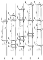
- 5 (A) to 5 (E) are examples of interference signals.
- 5 (A), 5 (B), 5 (C), 5 (D), and 5 (E) show interference signals obtained based on measurement lights B11, B21, B31, B41, and B51, respectively. This is an example.
- the measurement light B11 is directly applied to the portion of the tooth TO without the gum GU (see FIG. 4), and the intensity of light reflected from the surface of the tooth TO increases. For this reason, as shown in FIG. 5A, based on the reflected light from the surface TO1 on the left side of the tooth TO by the measurement light B11, as shown in FIG. Occurs.
- the measurement light B11 is also reflected on the inner surface TO2 on the back surface side of the tooth TO, and an interference signal S12 is generated at time t12 based on the reflected light as shown in FIG. 5A.
- the reflected light from the inner surface TO2 on the back side of the tooth TO is attenuated as the measurement light B11 travels inside the tooth TO which is the object to be measured.
- the amount of reflection is smaller than the light reflected from the surface TO1. Therefore, if the reflected light R11 from the reflecting surface 41A is not used, the level of the interference signal S12 becomes a level L12, which is a level that is much lower than the level of the interference signal S11 (level reduction).
- the interference signals S11 and S12 are generated using the reflected light R11 from the reflection surface 41A in addition to the reflection of the measurement light B11 on the inner surface TO2 on the back surface side of the tooth TO.
- the interference signal S12 is generated using the reflected light R11 from the reflection surface 41A (the interference signal S11 is also reflected light R11 from the reflection surface 41A).
- the level of the interference signal S12 is prevented from being greatly reduced as compared with the level L11 of the interference signal S11.
- the reflected light intensity from each of the inner surface TO2 on the side and the inner surface on the back side of the right gum GU is increased.
- the left side surface GU1 of the gum GU, the inner side GU of the back side of the left side gum GU2, the surface TO1 of the tooth TO1, the inner side TO2 of the back side of the tooth TO, and the right side gum As shown in FIG.
- interference signals S21, S22, S23, S24, and S25 are generated at times t21, t22, t23, t24, and t25 based on the respective reflected lights from the inner surface on the back surface side of the GU.
- the time difference ⁇ t21 from the time t21 to the time t22 indicates the thickness ⁇ 21 of the gum GU at the portion irradiated with the measurement light B21
- the time difference ⁇ t22 from the time t22 to the time t23 is the periodontal pocket at the portion irradiated with the measurement light B21.
- the distance between the gaps of PP (the distance of the gap between the tooth TO and the gum GU) ⁇ 22
- the time difference ⁇ t23 from time t23 to time t24 indicates the thickness ⁇ 23 of the tooth TO where the measuring light B21 is irradiated
- the time difference ⁇ 24 from t24 to time t25 indicates the thickness ⁇ 24 of the gum GU on the right side of the tooth TO at the portion irradiated with the measurement light B21.
- the level L24 of the interference signal S24 and the level L25 of the interference signal S25 become the interference signals S21, S22, Or, it is greatly reduced as compared with S23 (the level decrease is indicated by a chain line C2).
- each of the interference signals S21, S22, S23, S24, and S25 is generated using the reflected light R21 of the measurement light B21. Therefore, as shown in FIG. 5B, the levels of the interference signal S24, the interference signal S25, and the like are prevented from being significantly reduced.
- the measurement light B31 causes the left surface GU1, the left inner surface GU of the left gum GU, the inner surface GU2 of the left tooth GU, the inner surface TO2 of the lower surface of the tooth TO and the inner surface TO2 of the right gum GU to be exposed. And the intensity of the reflected light from each of them increases.
- the left side surface GU1 of the gum GU, the inner side GU on the back side of the left side gum GU2, the front side TO of the tooth TO1, the inner side TO2 of the back side of the tooth TO, and the right side gum As shown in FIG.
- interference signals S31, S32, S33, S34, and S35 are generated at times t31, t32, t33, t34, and t35 based on the respective reflected lights from the inner surface on the back surface side of the GU.
- the time difference ⁇ t31 from time t31 to time t32 indicates the thickness ⁇ 31 of the gum GU at the portion irradiated with the measurement light B31
- the time difference ⁇ t32 from time t32 to time t33 is the periodontal pocket at the portion irradiated with the measurement light B31.
- the distance between the gaps of PP (the distance of the gap between the tooth TO and the gum GU) ⁇ 32 is shown, and the time difference ⁇ t33 from time t33 to time t34 is the thickness ⁇ 33 of the tooth TO where the measurement light B31 is irradiated.
- the time difference ⁇ 34 from t34 to time t35 indicates the thickness ⁇ 34 of the gum GU on the right side of the tooth TO in the portion irradiated with the measurement light B31.
- the level L34 of the interference signal S34 and the level L35 of the interference signal S35 are changed to the interference signals S31, S32, Or, it is greatly reduced as compared with S33 (the level decrease is indicated by a chain line C3).
- each of the interference signals S31, S32, S33, S34, and S35 is generated using the reflected light R31 of the measurement light B31. Therefore, as shown in FIG. 5C, the levels of the interference signal S34 and the interference signal S35 are prevented from being significantly reduced.
- the left surface GU1, the left inner surface GU2 of the left gum GU, the inner surface GU2 of the tooth TO, the inner surface TO2 of the tooth TO rear surface, and the inner surface of the right gum GU on the rear surface are formed by the measurement light B41.
- the intensity of the reflected light from each of them increases.
- FIG. 5 (D) the left side surface GU1 of the gum GU, the inner side GU of the back side of the left side gum GU2, the front side TO of the tooth TO1, the inner side TO2 of the back side of the tooth TO, and the right side gum
- FIG. 5 (D) the left side surface GU1 of the gum GU, the inner side GU of the back side of the left side gum GU2, the front side TO of the tooth TO1, the inner side TO2 of the back side of the tooth TO, and the right side gum
- interference signals S41, S42, S43, S44, and S45 are generated at times t41, t42, t43, t44, and t45 based on the respective reflected lights from the inner surface on the back surface side of the GU.
- the time difference ⁇ t41 from time t41 to time t42 indicates the thickness ⁇ 41 of the gum GU at the portion irradiated with the measurement light B41
- the time difference ⁇ t42 from time t42 to time t43 is the periodontal pocket at the portion irradiated with the measurement light B41.
- the distance between the gaps of PP (the distance of the gap between the tooth TO and the gum GU) ⁇ 42, and the time difference ⁇ t43 from time t43 to time t44 indicates the thickness ⁇ 43 of the tooth TO at the portion irradiated with the measurement light B41.
- the time difference ⁇ 44 from t44 to time t45 indicates the thickness ⁇ 44 of the gum GU on the right side of the tooth TO in the portion irradiated with the measurement light B41.
- the level L44 of the interference signal S44 and the level L45 of the interference signal S45 become the interference signals S41, S42, Or, it is greatly reduced as compared with S43 (the level decrease is indicated by a chain line C4).
- each of the interference signals S41, S42, S43, S44 and S45 is generated using the reflected light R41 of the measurement light B41. Therefore, as shown in FIG. 5D, the levels of the interference signal S44, the interference signal S45, and the like are prevented from being significantly reduced.
- the measurement light B51 causes the left surface GU1 of the gum GU and the inner surface GU2 of the rear surface of the left gum GU (the same surface as the surface TO1 of the tooth TO because the periodontal pocket PP is not formed) and the tooth TO.
- the reflected light intensity from each of the inner surface TO2 on the back side and the inner surface on the back side of the right gum GU is increased.
- FIG. 5 (E) the left side surface GU1 of the gum GU, the inner surface GU2 on the back side of the left gum GU (the surface TO1 of the tooth TO), the inner surface TO2 on the back side of the tooth TO, and the right side of the right side.
- FIG. 5 (E) the left side surface GU1 of the gum GU, the inner surface GU2 on the back side of the left gum GU (the surface TO1 of the tooth TO), the inner surface TO2 on the back side of the tooth TO, and the right side of the right side.
- interference signals S51, S52, S53, and S54 are generated at times t51, t52, t53, and t54 based on the respective reflected lights from the inner surface on the back side of the gum GU.
- the time difference ⁇ t51 from the time t51 to the time t52 indicates the thickness ⁇ 51 of the gum GU at the portion irradiated with the measurement light B51
- the time difference ⁇ t52 from the time t52 to the time t53 is the thickness of the tooth TO at the portion irradiated with the measurement light B51.
- the time difference ⁇ 53 from the time t53 to the time t54 indicates the thickness ⁇ 53 of the gum GU on the right side of the tooth TO where the measurement light B51 is irradiated.
- the level L53 of the interference signal S53 and the level L54 of the interference signal S54 are compared with the interference signal S51 or S52. (The level decrease is indicated by a chain line C5).
- each of the interference signals S51, S52, S53 and S54 is generated using the reflected light R51 of the measurement light B51. Therefore, as shown in FIG. 5E, the levels of the interference signal S53, the interference signal S54, and the like are prevented from being significantly reduced.
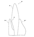
- FIG. 6 is an example of the optical tomographic image IM.
- the optical tomographic image IM includes an optical tomographic image Igu1 of the gum GU on the side irradiated with the measuring lights B11 to B51 and the like, an optical tomographic image Ito of the tooth TO and the gum GU on the side irradiated with the measuring lights B11 to B51 and the like. Includes an optical tomographic image Igu2 of the gum GU on the opposite side. Such an optical tomographic image IM is displayed on the display screen of the display device 6.
- the attenuation of the measurement lights B11 to B51 causes the optical tomogram of the gum GU on the opposite side to the incident surface side of the measurement lights B11 to B51.
- the image Igu2 is often not displayed clearly, in this embodiment, an interference signal S12 with a good S / N is generated using the reflected light R11 to R51, and the optical tomographic image IM is generated.
- the optical tomographic image Igu2 is also clearly displayed.
- the signal processing circuit 5 extracts the contour of the optical tomographic image Igu1 of the gum GU and the optical tomographic image Ito of the tooth TO, so that the signal processing circuit 5 calculates the depth ⁇ d of the periodontal pocket PP.
- a periodontal pocket is not formed between the optical tomographic image Igu2 and the optical tomographic image Ito of the tooth TO, but a periodontal pocket is formed between the optical tomographic image Igu2 and the optical tomographic image Ito of the tooth TO. In the case where is formed, the depth of the periodontal pocket can also be calculated.
- the optical tomographic image IM of the gum GU and the tooth TO is generated, and the contour of the optical tomographic images Igu1 and Ito is extracted from the generated optical tomographic image IM, thereby obtaining the depth of the periodontal pocket PP.
- the depth ⁇ d is calculated, the depth ⁇ d of the periodontal pocket PP is calculated by calculation without generating the optical tomographic images Igu1 and Ito (the optical tomographic images Igu1 and Ito may be generated). You may.
- the fluctuation width of the measuring beams B11 to B51 is such that the depth ⁇ d of the periodontal pocket PP can be measured in one scan even for severe periodontal disease.
- the measurement is performed a plurality of times (at least two places) at different upper and lower positions using the inspection head 20.
- the data on the depth ⁇ d of the periodontal pocket may be generated in the signal processing circuit (periodontal pocket data generating means) 5 based on the interference signal output from the photodiode 4.
- the emission member 30 of the inspection head 20 may use a single scan (measurement) to output measurement light having an amplitude corresponding to the range of measurement light B11 to B31 (equivalent to the range of B31 to B51) shown in FIG. Assume that it can be emitted.
- the first scanning (measurement) by the inspection head 20 is performed at a position where the measurement light can be emitted in a range corresponding to the measurement lights B11 to B31 shown in FIG.
- the interference signal obtained based on the measurement light emitted in the range of measurement light B11 to B31 shown in FIG. 4 in the first scan the upper half of the gum GU and the tooth TO shown in FIG.
- Optical tomographic images Igu1, Igu2 and Ito are obtained.
- the inspection head 20 is moved downward. It is assumed that the measurement light is emitted from the inspection head 20 to the range corresponding to the measurement lights B31 to B51 shown in FIG. 4 by the second scan performed at the position after the movement. In this case, an optical signal in the lower half of the gum GU and the tooth TO shown in FIG. 4 is obtained from the interference signal obtained based on the measurement light emitted in the range of the measurement light B31 to B51 shown in FIG. Images Igu1, Igu2 and Ito are obtained.
- the two optical tomographic images obtained by the measurement at the two different upper and lower positions are synthesized by the signal processing circuit 5, so that the optical tomographic images of the gum GU and the tooth TO shown in FIG. 4 are obtained.
- the optical tomographic images Igu1, Igu2, and Ito of the upper half of the gum GU and the tooth TO are combined with the optical tomographic images Igu1, Igu2, and Ito of the lower half so that overlapping portions overlap, and an optical tomogram obtained by one scan It goes without saying that continuity of the optical tomographic images in the vertical direction is ensured so that the same optical tomographic images as the images Igu1, Igu2 and Ito can be obtained.
- the second optical fibers 21 to 25 are arranged in one line, but may be arranged in two or more lines.
- the measurement light LM may be deflected also in the two-dimensional direction, and the measurement light may be guided to the optical fibers included in each row.
- the five second optical fibers 21 to 25 are not necessarily arranged in a straight line and may be curved in a curved line.
- FIGS. 7 to 12 show an example of the inspection head 20.
- FIGS. 7 to 12 are shown upside down with respect to FIGS. Assuming that FIGS. 7 to 12 show an upright state (or an upright state), FIGS. 1 and 4 show an upright state (or an upright state).
- sliding groove 52 is formed in sliding surface 51 of rectangular parallelepiped holding portion 50.
- the emission member 30 has a three-layer structure, and a deformable member 32 made of a resin or the like that can be deformed by applying a pressure between a relatively hard plate member 31 and a deformable plate member 33. Is sandwiched.
- the plate member 33 is deformed following the deformation of the deformable member 32.
- the front surface of one plate member 31 is an incident surface 31A
- the rear surface of the other plate member 33 is an emission surface 33A that emits B51 from measurement light B11.
- the reflecting member 40 also has a three-layer structure, and a deformable member 42 made of a resin or the like that can be deformed by applying pressure between the sheet-like mirror 41 and the relatively hard plate-like member 43. Is sandwiched.
- the surface in front of the sheet-like mirror 41 is a reflection surface. Since the emitting member 30 includes the deforming member 32 and the reflecting member 40 includes the deforming member 42, the tooth TO and the gum GU are sandwiched between the emitting member 30 and the reflecting member 40. Then, the tooth TO or the gum GU comes into close contact with the emission surface 33A and the reflection surface 41A.
- the emitting member 30 and the reflecting member 40 do not necessarily have to have a three-layer structure, and need not be deformable by the deformable members 32 and 42 or the like.
- the end surface of the deformable member 32 may be an emission surface without the plate-like member 33 of the emission member 30, and the measurement light B11 to B51 may be emitted.
- the emission surface 33A and the reflection surface 41A do not have to be in close contact with the tooth TO or the gum GU, and the emission member 30 and the reflection member 40 do not necessarily need to be deformed.
- FIG. 8 is a cross-sectional view taken along the line VIII-VIII of FIG.
- a hollow portion 53 is formed in the holding portion 50, and an upper portion of the hollow portion 53 is a sliding groove 52.
- a part of the lower part of the reflecting member 40 is a narrow part 44 having a narrow width, and a lower part of the narrow part 44 is a sliding part 45 having a width wider than the narrow part 44.
- the constricted portion 44 enters the sliding groove 52, and the reflecting member 40 slides along the sliding groove 52. Since the width of the sliding portion 45 is wider than the width of the sliding groove 52, the reflecting member 40 slides along the sliding groove 52 without coming off the holding portion 50.
- the other transmission member 62 of two transmission members 61 and 62 (see FIG. 9) described later is fixed to the sliding portion 45.
- the emission member 30 has the same configuration as the reflection member 40, and the emission member 30 slides along the sliding groove 52.
- the second optical fibers 21 to 25 are inserted into the entrance surface 31A outside the exit member 30, and the measurement beams B11 to B51 exit from the exit surface 33A opposite to the entrance surface 31A. .
- the measurement lights B11 to B51 are reflected on the reflection surface 41A of the reflection member 40 as described above.
- the holding surface 50 holds the emission surface 33A of the emission member 30 and the reflection surface 41A of the reflection member 40 in parallel.
- the bar-shaped gripping member 60 fixed to the lower surface of the holding unit 50 extends below the holding unit 50.
- the holding section 50 includes a fixing section 70 fixed to the holding section 50 and a bending section 80 that bends at a predetermined angle around a bending axis 75 (an example of a rotation axis).
- a concave portion 73 is formed in a lower portion of the fixing portion 70, and a convex portion 83 formed in an upper portion of the bent portion 80 enters the concave portion 73.
- the lower surface of the fixing portion 70 is an arc surface 74 formed in a protruding arc shape
- the upper surface of the bent portion 80 is an arc surface 84 formed in a concave arc shape.
- the arc surface 74 of the fixing portion 70 and the arc surface 84 of the bent portion 80 face each other, and the convex portion 83 formed above the bent portion 80 enters the concave portion 73.
- the bending shaft 75 penetrates the concave portion 73 and the convex portion 83 such that the direction of the central axis of the bending shaft 75 is the same as the emission direction of the measurement light beams B11 to B51. As a result, the bent portion 80 can be bent around the bending shaft 75 with respect to the fixed portion 70.
- Operation buttons 64 are formed on the surface of the bent portion 80. By operating the operation button 64 upward, the emission member 30 and the reflection member 40 are separated from each other, and by operating the operation button 64 downward, the emission member 30 and the reflection member 40 approach each other (the reverse of them). May be).
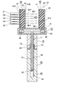
- FIG. 9 is a cross-sectional view taken along line IX-IX of FIG.
- fixed portion 70 is connected to hollow portion 53 in holding portion 50, and has hollow portion 71 extending downward in FIG.
- a hollow portion 81 extending in the direction is formed.
- Two transmission members 61 and 62 pass through the hollow portions 81 and 71 and the hollow portion 53.
- One transmission member 61 has a front end fixed to the sliding portion 34 of the emission member 30, and a rear end fixed to an operation shaft 63 connected to the operation button 64.
- the front end of the other transmission member 62 is fixed to the sliding portion 45 of the reflection member 40, and the rear end is fixed to the operation shaft 63 connected to the operation button 64.
- These two transmission members 61 and 62 are made of a resin, a spring, or the like, which is flexible but can transmit the pressing force of the emitting member 30 and the reflecting member 40 when a pressing force is applied.
- the operation button 64 When the operation button 64 is raised, a force that pushes the operation button 64 is applied to the operation shaft 63 of the operation button 64, and a force that pushes the emission member 30 by one of the transmission members 61 fixed to the operation shaft 63 is applied.
- a pushing force is applied to the reflecting member 40 by the other transmitting member 62 fixed to the shaft 63.
- a force is applied in a direction in which the emitting member 30 and the reflecting member 40 separate from each other, and as shown in FIGS. 5 and 7, the emitting surface 30A and the reflecting surface 41A maintain a parallel state, and the emitting member 30 and the reflecting member 40 Separate.
- the transmission members 61 and 62 function as a second transmission member.
- FIG. 10 is a perspective view of the inspection head 20, showing a state in which the emission member 30 and the reflection member 40 are close to each other.
- FIG. 11 is a cross-sectional view taken along line XI-XI of FIG. .
- the two transmission members 61 and 62 are pulled downward.
- the emission member 30 is pulled by one transmission member 61, and the reflection member is pulled by the other transmission member 62.
- the transmission members 61 and 62 function as first transmission members.
- FIG. 12 is a side view showing a state where the gripping member 60 is bent.
- the gripping member 60 may hinder the sandwiching. For this reason, the gripping member 60 is freely bendable about a bending shaft 75.
- the direction of the axis of the bending axis 75 is the same as the emission direction of the measurement light beams B11 to B51, but the axis of the bending axis 75 is centered on the axis in the longitudinal direction of the gripping member 60.
- the gripping member 60 may be fixed to the holder 50 so that the axis is perpendicular to the optical axis of the measurement light beams B11 to B51.
- the emission member 30 can be bent so as to fall forward or backward.
- FIG. 13 shows a modified example, and is a cross-sectional view of the inspection head 20 and corresponds to FIG. 13, the same components as those shown in FIG. 9 and the like are denoted by the same reference numerals, and description thereof will be omitted.
- a spring 65 having both ends fixed to the sliding portion 34 of the emission member 30 and the sliding portion 45 of the reflecting member 40 in the hollow portion 53 of the holding portion 50 is provided.
- the spring 65 may be a compression spring or a tension spring.
- the spring 65 is a compression spring (an example of a compression member)
- the operation button 64 is raised. State.
- the operation button 64 is lowered against the force of the spring 65, the operation member 64 is pulled by the force of the two transmission members 61 and 62 (functioning as the first transmission member), and the emission member 30 and the reflection member 40 approach.
- the operation button 64 is released, the emission member 30 and the reflection member 40 are separated by the compression force of the spring 65.
- the transmitting members 61 and 62 may be in the form of a string because a pulling force may be applied so that the emitting member 30 and the reflecting member 40 approach each other.
- the spring 65 is a tension spring (an example of a tension member)
- the operation button 64 is raised against the force of the spring 65, the operation member 64 is pushed by the forces of the two transmission members 61 and 62 (functioning as a second transmission member), and the light emitting member 30 and the reflecting member 40 are separated.
- the emission member 30 and the reflection member 40 are provided in the inspection head 20A so as to be slidable, so that the emission member 30 and the reflection member 40 can approach and separate from each other.
- one of the emission member 30 and the reflection member 40 is fixed to the holding portion 50A, and the other of the emission member 30 and the reflection member 40 is provided on the inspection head 20A so as to be slidable. May be approachable and separable.
- FIGS. 14 and 15 show another modification.
- FIG. 14 is a perspective view of the inspection head 20A.
- a sliding groove 52A is formed in a sliding surface 51A of the holding section 50A of the inspection head 20A along the longitudinal direction of the holding section 50A.
- the emitting member 35 has a deformable member 37 sandwiched between a plate-shaped member 36 and a deformable plate-shaped member 38.
- the plate member 38 is deformed following the deformation of the deformable member 37.
- the second optical fibers 21 to 25 are inserted into the entrance surface 36A of the exit member 35, and the measurement beams B11 to B51 exit from the exit surface 38A.
- the sliding groove 52A is formed so that the emission direction of the measurement light beams B11 to B51 and the sliding direction of the emission member 35 are the same.
- a reflecting member 49 is fixed to one end of the holding section 50A.
- the reflecting member 49 has a deformable member 47 sandwiched between a sheet-like mirror 46 and a plate-like member 48.
- the surface of the sheet-like mirror 46 is a reflection surface 46A.
- the reflection member 49 does not slide but may be slidable. Further, the emission member 35 may be fixed to one end of the holding portion 50A, and the reflection member 49 may be slidable.
- a cavity as shown in FIG. 9 and the like is formed inside the holding portion 50A to slide the emission member 35.
- An opening 90 is formed on the side surface of the holding portion 50A.
- a worm 91 is rotatably mounted inside the opening 90.
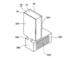
- FIG. 15 is a perspective view of the emission member 35.
- the emission member 35 has a narrow portion 39A having a narrow width similarly to the reflection member 40 shown in FIG. 8 and the like, and a sliding portion 39B is formed in the narrow portion 39A.
- the sliding portion 39B extends in the emission direction of the measurement light B21 from the measurement light B21, and the emission member 35 has a substantially L-shape when viewed from the side.
- a rack 39D is formed below the side surface 39C of the sliding portion 39B.
- a gripping member 60A is fixed to the lower surface of the holding portion 50A.
- the holding member 60A includes a fixed portion 70 fixed to the holding portion 50A and a bent portion 80A that can be bent with respect to the fixed portion 70 by a bending shaft 75.
- the inspection head 20A as shown in FIGS. 14 and 15 can also approach and separate while maintaining the parallel state between the emission surface 38A of the emission member 35 and the reflection surface 46A of the reflection member 49.
- the measurement light B21 to B25 is irradiated to the tooth TO or the tooth TO and the gum GU using the five optical fibers 21 to 25, but the five optical fibers 21 to 25 are not provided.
- the measurement light LM emitted from the first optical fiber 7 may be directly irradiated to the tooth TO or the tooth TO and the gum GU.
- the emission end face 7B of the measurement light LM of the first optical fiber 7 is By connecting to the inspection head 20 and moving the inspection head 20 up and down (the Z direction and the ⁇ Z direction in FIG. 1), the plurality of measurement lights LM and the reflected lights R11 to R51 corresponding to the measurement lights B11 to B51 described above are changed. The corresponding reflected light is obtained. That is, the measuring light LM, the measuring lights B21 to B25 and the like need only be applied to the teeth TO and the gums GU, and the optical fibers 21 to 25 need not be used.
- the measuring light LM is distributed to the five optical fibers 21 to 25 using the deflecting mirror 13, but the measuring light LM is transmitted using the crystal deflecting element (not shown).
- the five optical fibers 21 to 25 may be distributed.
- the measuring light LM that is incident is deflected according to the voltage applied to the crystal deflecting element.
- the optical fibers 21 to 25 are connected to the deflecting device 10, but the optical fibers 21 to 25 are built in the deflecting device 10, and the deflecting device 10 and the emission member 30 are integrated. You may.
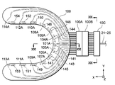
- FIGS. 16 to 22 show another embodiment, which is an example of a mouthpiece 100 as an inspection head. Specifically, the mouthpiece 100 corresponds to one mode of the holding unit.
- FIG. 16 The upper part of FIG. 16 is a perspective view of the mouthpiece 100, and the lower part of FIG. 16 is a gum GU and lower teeth TE (central incisors 121 and 122, side incisors 123 and 124) on which the mouthpiece 100 is mounted. , Canines 125 and 126, first premolars 127 and 128, second premolars 129 and 130, first molars 131 and 132, and second molars 133 and 134).
- the mouthpiece 100 is made of a flexible material, and holds a plurality of optical fibers included in the mouthpiece 100 movably independently in the optical axis direction of the optical fiber. However, it is not necessary to be movable.
- FIG. 17 shows a state in which the mouthpiece 100 is attached to the tooth TE and the gum GU.
- a depression is formed inside the mouthpiece 100 so that the inner surface of the mouthpiece 100 is in close contact with the surface of the tooth TE and the surface of the gum GU.
- FIG. 18 is a plan view of the mouthpiece 100.
- the mouthpiece 100 includes a large number of optical fibers 101A to 114A and the like (for simplicity, these optical fibers 101A to 114A and the like are indicated by broken lines).
- a large number of optical fibers extend from the front of the mouthpiece 100 (the right side in FIG. 17) to the outside of the mouthpiece 100.
- Many optical fibers are separably connected by a pair of connectors (connector 100A and connector 100B).
- the optical fibers 101A to 114A extending from the connector 100B are connected to one end of the deflecting device 10C, and five optical fibers 21 to 25 are connected to the other end of the deflecting device 10C.
- the deflecting device 10C deflects the measuring light LM output from the optical fibers 21 to 25 using a deflecting mirror provided inside the deflecting device 10C, and deflects the optical fibers 101A to 101E, 102A to 102E, and 103A to 103E, 104A.
- 105A to 105E, 106A to 106E, 107A to 107E, 108A to 108E, 109A to 109E, 110A to 110E, 111A to 111E, 112A to 112E, 113A to 113E or 114A to 114E (see FIG. 19). Propagate the LM.
- a position facing the other end surface of the optical fibers 101A to 114A or the like (the end surface not connected to the connector 100A and serving as an emission surface for emitting parallel measurement light) is provided via a recess.
- the reflection members 141 to 154 and the like are arranged.
- FIG. 19 is a sectional view taken along the line XIX-XIX in FIG. In FIG. 19, hatching is omitted.
- the deflecting device 10C includes a number of optical fibers 101A to 101E, 102A to 102E, 103A to 103E, 104A to 104E, 105A to 105E, 106A to 106E, 107A to 107E, and 108A to 108E extending from the mouthpiece 100 to the outside.
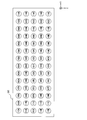
- Optical fibers 101A to 101E, 102A to 102E, 103A to 103E, 104A to 104E, 105A to 105E, 10A to 106E, 107A to 107E, 108A to 108E, 109A to 109E, 110A to 110E, 111A to 111E, 112A to 112E, 113A to 113E and 114A # to 114E are arranged in a line in the Z-axis direction (vertical direction).
- the measurement light LM emitted from the inside of the optical fibers 21 to 25 is emitted from the optical fibers 101A to 101E, 102A to 102E, 103A to 103E, 104A to 104E, 105A to 105E, 106A to 106E, 107A to 107E and 108A by the deflecting device 10C.
- the deflecting device 10C shown in FIGS. 18 and 20 deflects the measurement light LM emitted from the inside of the optical fiber 21 into the one-dimensional direction.
- the deflecting device 10C may deflect the measurement light LM emitted from the inside of the first optical fiber 7 in a two-dimensional direction.
- a first optical fiber 7 may be connected to the deflecting device 10C.
- FIG. 20 is a plan view showing a state where the mouthpiece 100 is mounted on the tooth TE and the gum GU.
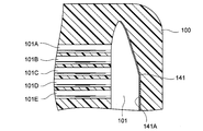
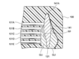
- FIG. 21 is a sectional view taken along the line XXI-XXI in FIG. 18, and FIG. 22 is a sectional view taken along the line XXII-XXII in FIG.
- the optical fibers 101A to 101E arranged in a line are arranged by the mouthpiece 100 such that the light emitting surface of the optical fibers 101A to 101E is exposed from the contact surface 86 of the tooth TE and the gum GU. Is held.
- the reflection member 141 is disposed at a position facing the emission end faces of the optical fibers 101A to 101E.
- the surface of the reflection member 141 is a reflection surface 141A.
- the mouthpiece 100 is made of an elastically deformable resin or the like. When the tooth TE and the gum GU are inserted into the space 101 between the emission end surfaces of the optical fibers 101A to 101E and the reflecting surface 141A, the mouthpiece 100 is moved from the optical fiber 101A.
- the emission end face of 101E is in close contact with the surface of the tooth TE or the gum GU, and the reflecting surface 141A is in close contact with the back surface of the tooth TE or the gum GU.
- the exit surfaces of the optical fibers 101A to 101E adheres to the surface and the outer surface of the central incisor 121.
- the exit surfaces of the optical fibers 102A to 102E come into close contact with the outer surfaces of the gum GU and the central incisor 122 surrounding the central incisor 122, and
- the emission surfaces of the fibers 103A to 103E are in close contact with the gum GU surrounding the side incisors 123 and the outer surface of the side incisors 123, and the emission surfaces of the optical fibers 104A to 104E are covering the side incisors 124.
- the emission surfaces of the optical fibers 105A to 105E are in close contact with the outer surfaces of the gums GU and the canines 125 surrounding the canines 125, and the emission surfaces of the optical fibers 106A to 106E are in close contact with the outer surfaces of the side incisors 124.
- the gum GU surrounding the canine tooth 126 and the outer surface of the canine tooth 126 are in close contact.
- the exit surfaces of the optical fibers 107A to 107E are in close contact with the gum GU surrounding the first premolar 127 and the outer surface of the first premolar 127, and the exit surfaces of the optical fibers 108A to 108E are the first premolar 128.
- the outer surfaces of the gum GU and the second premolar 129 which are in close contact with the outer surfaces of the gum GU and the first premolar 128 enclosing the second premolar 129 so that the output surfaces of the optical fibers 109A to 109E wrap the second premolar 129.
- the output surfaces of the optical fibers 110A to 110E are in close contact with the gum GU surrounding the second premolar 130 and the outer surfaces of the second premolars 130, and the output surfaces of the optical fibers 111A to 111E are the first large.
- the gum GU surrounding the molar 131 and the outer surface of the first molar 131 are brought into close contact with each other, and the output surfaces of the optical fibers and the optical fibers 112A to 112E are the first molar.
- the emission surfaces of the optical fibers 113A to 113E are in close contact with the external surfaces of the gum GU and the first molar 132 surrounding the gum GU and the second molar 133 surrounding the second molar 133.
- the output surfaces of the optical fibers 114A to 114E are in close contact with the outer surface of the second molar 134.
- the measurement light LM emitted from the second optical fibers 21 to 25 is deflected and enters the optical fibers 101A to 101E, the measurement light LM irradiates the gum GU and the central incisor 121 surrounding the central incisor 121. , The central incisor 121 and the gum GU.
- the measuring light LM transmitted through the gum GU or the central incisor 121 irradiates the reflecting surface 141A and is reflected from the reflecting surface 141A.
- the reference light LR Together with the photodiode 4 to obtain an optical tomographic image of the gum GU surrounding the central incisor 121 and the central incisor 121. Since the measurement light LM reflected from the reflection surface 141A is used, an interference signal having a good S / N can be obtained, and an optical tomographic image that is relatively easy to see can be obtained.
- the measurement light LM emitted from the second optical fibers 21 to 25 is deflected and enters the optical fibers 102A to 102E, the measurement light LM irradiates the gum GU surrounding the central incisor 122 and the central incisor 122. Therefore, an optical tomographic image of the gum GU surrounding the central incisor 122 and the central incisor 122 is obtained.
- the measurement light LM emitted from the second optical fibers 21 to 25 is deflected and enters the optical fibers 103A to 103E, the measurement light LM irradiates the gum GU and the side incisors 123 surrounding the side incisors 123.
- an optical tomographic image of the gum GU surrounding the lateral incisor 123 and the lateral incisor 123 is obtained.
- the measurement light LM emitted from the second optical fibers 21 to 25 is deflected and enters the optical fibers 104A to 10E, the measurement light LM irradiates the gum GU and the side incisors 124 surrounding the side incisors 124. Therefore, an optical tomographic image of the gum GU surrounding the lateral incisor 124 and the lateral incisor 124 is obtained.
- the measurement light LM emitted from the second optical fibers 21 to 25 When the measurement light LM emitted from the second optical fibers 21 to 25 is deflected and incident on the optical fibers 105A to 105E, the measurement light LM irradiates the gum GU surrounding the canine tooth 125 and the canine tooth 125. The optical tomographic image of the gum GU and the canine 125 enclosing is obtained.
- the measurement light LM emitted from the second optical fibers 21 to 25 is deflected and enters the optical fibers 106A to 106E, the measurement light LM irradiates the gum GU surrounding the canine tooth 126 and the canine tooth 126.
- the optical tomographic image of the gum GU and the canine 126 enclosing the GU is obtained.
- the measurement light LM emitted from the second optical fibers 21 to 25 is deflected and enters the optical fibers 107A to 107E
- the measurement light LM transmits the gum GU surrounding the first premolar 127 and the first Since the molar 127 is irradiated, an optical tomographic image of the gum GU surrounding the first molar 127 and the first molar 127 is obtained.
- the measurement light LM emitted from the second optical fibers 21 to 25 is deflected and enters the optical fibers 108A to 108E
- the measurement light LM causes the gums GU and the first premolars 128 surrounding the first premolars 128 to pass through.
- the measurement light LM emitted from the second optical fibers 21 to 25 When the measurement light LM emitted from the second optical fibers 21 to 25 is deflected and enters the optical fibers 110A to 110E, the measurement light LM causes the gum GU and the second premolar 130 surrounding the second premolar 130 to pass through. Since irradiation is performed, an optical tomographic image of the gum GU surrounding the second premolar 130 and the second premolar 130 is obtained.
- the measurement light LM emitted from the second optical fibers 21 to 25 when the measurement light LM emitted from the second optical fibers 21 to 25 is deflected and enters the optical fibers 111A to 111E, the measurement light LM outputs the gum GU and the first molar wrapping the first molar 131. Since the light 131 is irradiated, an optical tomographic image of the gum GU surrounding the first molar 131 and the first molar 131 is obtained.
- the measurement light LM emitted from the second optical fibers 21 to 25 is deflected and enters the optical fibers 112A to 112E, the measurement light LM causes the gums GU and the first molars 132 surrounding the first molars 132 to be illuminated.
- the measurement light LM emitted from the second optical fibers 21 to 25 When the measurement light LM emitted from the second optical fibers 21 to 25 is deflected and enters the optical fibers 114A to 114E, the measurement light LM causes the gums GU and the second molars 134 surrounding the second molars 134 to pass through. Since irradiation is performed, an optical tomographic image of the gum GU surrounding the second molar 134 and the second molar 134 is obtained.
- the reflection members 142, 143, 144, 145, 146, 147, 148, 149, 150, 151, 152, 153, and 154 are also opposed to the emission end face on the distal end side with respect to the end faces 112E, 113A to 113E, and 114A to 114E.
- An interference signal having a good S / N can be generated, and an optical tomographic image that is relatively easy to see can be obtained because an interference signal is generated using reflected light from these reflection members 142-154. Be able to It made.
- the mouthpiece 100 is attached to the tooth TE and the gum GU, and the measurement light LM is propagated from the second optical fibers 21 to 25, so that the measurer includes each tooth TO and each tooth TO to be measured.
- the depth of the plurality of periodontal pockets corresponding to the plurality of teeth TE can be detected without manually positioning the gums GU sequentially. As a result, it is possible to reduce the troublesomeness of the measurer and reduce the measurement time as compared with the case where the measurer sequentially positions each periodontal pocket corresponding to each tooth TO.
- the above-mentioned mouthpiece 100 can be formed by putting a number of optical fibers into a mold of the mouthpiece 100 prepared in advance and pouring a resin of a flexible material.
- the mouthpiece 100 may be formed by molding the shape of the mouthpiece 100 with a resin of a flexible material, and then forming the above-described space and passing a number of optical fibers through the space. May be generated.
- the mouthpiece 100 for the lower jaw was described.
- the depth of the periodontal pocket can be detected in the same manner for the mouthpiece 100 for the upper jaw instead of the lower jaw.
- an optical fiber is inserted into the mouthpiece 100 so as to detect the depth of the periodontal pocket on the inner surface of the tooth TE. It may be provided. In that case, the optical fiber would be provided in the mouthpiece 100 such that the emission surface of the optical fiber hits the inner surface of the tooth TE.
- the output end face of one row of optical fibers is configured to correspond to one tooth, but the output end face of two or more rows of optical fibers is corresponding to one tooth. May be applied.
- detachable connectors 100A and 100B are provided on the distal end side of the deflecting device 10C.
- a connector an example of a coupling member for detachably coupling the optical fibers 21 to 25 between the distal ends of the optical fibers 21 to 25 and the proximal end of the optical fibers 21 to 25 shown in FIG. May be provided.
- the mouthpiece 100 inspection head
- the mouthpiece 100 can be replaced relatively easily.
- the part including the tip of the optical fiber array that comes into contact with the subject's mouth can be removed, this part can be discarded and replaced with an unused part for each subject. Therefore, the degree of hygiene in periodontal disease examination can be increased. Further, since the discarded portion does not include relatively high members such as the deflection device, the running cost is reduced as compared with the case where these members are included in the discarded portion.
Landscapes
- Health & Medical Sciences (AREA)
- Life Sciences & Earth Sciences (AREA)
- Physics & Mathematics (AREA)
- Medical Informatics (AREA)
- Surgery (AREA)
- Veterinary Medicine (AREA)
- Public Health (AREA)
- Biophysics (AREA)
- Pathology (AREA)
- Engineering & Computer Science (AREA)
- Biomedical Technology (AREA)
- Heart & Thoracic Surgery (AREA)
- General Health & Medical Sciences (AREA)
- Molecular Biology (AREA)
- Animal Behavior & Ethology (AREA)
- Dentistry (AREA)
- Audiology, Speech & Language Pathology (AREA)
- Oral & Maxillofacial Surgery (AREA)
- Nuclear Medicine, Radiotherapy & Molecular Imaging (AREA)
- Radiology & Medical Imaging (AREA)
- General Physics & Mathematics (AREA)
- Dental Tools And Instruments Or Auxiliary Dental Instruments (AREA)
- Length Measuring Devices By Optical Means (AREA)
- Investigating Or Analysing Materials By Optical Means (AREA)
- Endoscopes (AREA)
Abstract
歯周病を検査する装置に用いられる検査ヘッド(20)において,平行光である測定光(B11)から(B15)が出射部(30)の出射面(32)から出射される。出射部(30)の出射面(32)に対向する位置に反射面(41)が形成されている反射部材(40)が設けられている。出射面(32)と反射面(41)とによって歯および歯茎を挟み,測定光(B11)から(B15)を出射する。歯および歯茎からの測定光(B11)から(B15)の反射光に加えて,反射面(41)からの測定光(B11)から(B15)の反射光を利用して干渉信号が生成される。S/Nの良好な干渉信号が得られる。
Description
この発明は,検査ヘッドおよび歯周病検査装置に関する。
歯周病の検査の一つとして歯周ポケットの深さを測ることが行われている。歯周ポケットの深さは,歯科医師等がポケット・プローブという棒状の測定器具を歯周ポケットの中に挿入して目視で測るのが一般的である。しかしながら,歯科医師等の力の加減,ポケット・プローブの挿入角度,目視誤差などにより測定結果が必ずしも正確でないことがある。また,検査時の歯茎からの出血等で,歯周病で無い患部への歯周病感染等も懸念される。このために,被検出物に光を照射して光断層情報から口腔内の情報を取得するOCT(optical coherence tomography)装置が考えられている(特許文献1)。
しかしながら,OCT装置から出射される測定光は,透過限界まで,透過,反射,干渉を繰り返し行うので,被検出物の内部を進むに連れて過光が減衰する。そのため,被検出物の厚みが大きくなるほど,得られる干渉信号のS/Nが悪くなる。このために,被検出物の正確な情報が得られないことがある。
この発明は,被検出物の厚みが大きくなることに起因した干渉信号のS/Nの低下を防止することを目的とする。
第1の発明は,低干渉光から分岐される測定光と参照光とを利用して歯周病を検査する装置に用いられる検査ヘッドにおいて,平行光である測定光を出射する出射面と,上記出射面に平行(ほぼ平行であればよい)であり,かつ上記出射面から出射される測定光を反射する反射面と,が形成されている保持部を備えていることを特徴とする。
上記出射面は出射部材に,上記反射面は反射部材にそれぞれ形成されており,上記保持部は,上記出射部材および上記反射部材を保持するとよい。
上記保持部は,たとえば,上記出射面と上記反射面とが平行状態を維持しつつ接近および離間可能に上記出射部材および上記反射部材を支持する。
一端部が上記保持部に固定されている棒状の把持部材をさらに備えてもよい。この場合,上記把持部材は,たとえば,上記出射光の光軸と同じ方向の直線を回転軸として所定の角度折り曲げ自在である。
上記出射面と上記反射面とが接近するように上記出射部材および上記反射部材の少なくとも一方に加える力を伝達する第1の伝達部材をさらに備えてもよいし,上記出射面と上記反射面とが離間するように上記出射部材および上記反射部材の少なくとも一方に加える力を伝達する第2の伝達部材をさらに備えてもよい。
上記出射面と上記反射面とが接近するように上記出射部材と上記反射部材とを引っ張る引っ張り部材をさらに備えてもよいし,上記出射面と上記反射面とが離間するように上記出射部材と上記反射部材とを離間させ力を与える圧縮部材をさらに備えてもよい。
上記保持部は,たとえば,歯茎の境目の歯の表面部分と歯茎の一部とに密着し,かつ可撓性材料からなるマウス・ピースである。この場合,好ましくは,装着することにより歯と歯茎の一部とが入り込む窪み部が形成されており,上記窪み部において歯を挟んで対向する2つの面のうち一方の面に上記出射面が形成され,かつ上記2つの面のうち他方の面に上記反射面が形成されているマウス・ピースである。
上記反射面は,たとえば,表面鏡または裏面鏡の反射面である。
第2の発明による歯周病検査装置は,上記検査ヘッド,低干渉光を測定光と参照光とに分岐する光分岐器,上記光分岐器によって分岐された測定光を平行光とする平行化素子,上記平行化素子によって平行光とされた測定光を,上記検査ヘッドに導光して上記出射面から出射させる光導波路,上記検査ヘッドの上記出射面から出射した測定光が歯茎または歯に照射されることにより歯茎または歯から反射された反射光および上記検査ヘッドの上記出射面から出射した出射光が上記検査ヘッドの上記反射面から反射された反射光と,上記光分岐器によって分岐された参照光が参照面によって反射された反射光と,を検出した干渉信号を出力する光検出器,ならびに上記光検出器から出力した干渉信号にもとづいて歯周ポケットの深さについてのデータを生成する歯周ポケット・データ生成手段を備えている。
第1の発明によると,出射面と平行な反射面が形成されているので,反射面から反射した測定光が得られる。出射面から出射した測定光だけでなく反射面から反射した測定光も用いて干渉信号を生成すれば,被測定物の厚みが大きくなることに起因する干渉信号のS/Nの低下を軽減できる。第2の発明によると,出射面から出射した測定光だけでなく,反射面から反射した測定光を用いて干渉信号を生成するので,被測定物の厚みが大きくなることに起因する干渉信号のS/Nの低下が軽減でき,歯周ポケットについて比較的正確なデータが得られる。
図1は,この発明の実施例を示すもので,歯周病検査装置の構成を示すブロック図である。
SLD(Super luminescent diode)などのような光源1から低干渉光(低コヒーレント光)Lが出射される。低干渉光Lは,ビーム・スプリッタ2(光分岐器の一例である)によって測定光LMと参照光LRとに分岐させられる。光源1からは低干渉光Lが出射されればよく,ガス・レーザ,半導体レーザ,レーザ・ダイオードなどの他の光源を用いてもよい。
ビーム・スプリッタ2によって分岐させられた測定光LMは,第1の光ファイバ7の測定光LMの入射端面7A(測定光LMの入射端面は,図1において基端側の端面となる)から第1の光ファイバ7に入射する。第1の光ファイバ7の測定光LMの出射端面(測定光LMの出射端面は,図1において先端側の端面となる)は偏向装置10に接続されている。偏向装置10には,5本(便宜上5本としているが5本よりも多くても少なくてもよい)の第2の光ファイバ21から25が接続されている。5本の光ファイバ21から25(光導波路の一例である)における測定光LMの入射端面のそれぞれに順に入射するように,第1の光ファイバ7における測定光LMの出射端面から出射した測定光LMが,偏向装置10によって偏向させられ,かつ平行化させられる。
歯周病検査装置の検査ヘッド20(詳細は,図7から図12などを参照)には保持部50が含まれている。この保持部50に測定光LMを出射する出射部材30が形成されている。出射部材30は,詳しくは後述するように(図7等を参照),2つの板状部材31と変形部材32とから構成されている。出射部材30と,出射部材30の出射面33Aから出射した測定光LMを反射する反射面41Aが形成されている反射部材40とが保持部50に保持されている。反射部材40も,詳しくは後述するように(図7等を参照),シート状の鏡41,変形部材42および板状部材43から構成されている。出射部材30の出射面33Aと反射部材40の反射面41Aとは平行となるように,出射部材30および反射部材40とが保持部50に保持されている。その保持部50には,ユーザが検査ヘッド20を把持する把持部材60が固定されている。第2の光ファイバ21から25の測定光LMの出射端面側の部分は出射部材30の入射面31Aから出射部材30内に入り込み,出射部材30内に固定されている。
第2の光ファイバ21から25に入射した測定光LMは,第2の光ファイバ21から25内を伝搬して出射部材30の出射面33Aから出射する。測定光LMは,測定対象である歯茎GUおよび歯TOに照射させられる。
測定対象である歯茎GUおよび歯TOに照射された測定光LMの一部は歯茎GUおよび歯TOから反射する。歯茎GUおよび歯TOから反射した測定光LMは,第2の光ファイバ21から25を通り,偏向装置10によって第1の光ファイバ7に導かれる。
また,測定光LMの一部は歯茎GUおよび歯TOを透過し,反射部材40の反射面41Aにおいて反射する。反射面41Aから反射した測定光LMも,歯茎GUおよび歯TOを透過し,第2の光ファイバ21から25を通り,偏向装置10によって第1の光ファイバ7に導かれる。
第1の光ファイバ7からは,歯茎GUおよび歯TOから反射した測定光LMならびに反射面41Aから反射した測定光LMが戻ってきて,ビーム・スプリッタ2において反射してフォトダイオード4(光検出器の一例である)に入射する。
また,ビーム・スプリッタ2において分岐させられた参照光LRは,参照光LRの進む方向およびその逆方向(図1に示す実施例においてはZ軸正方向および負方向)に移動自在な参照用ミラー3(参照面)において反射する。反射した参照光LRは,ビーム・スプリッタ2を透過してフォトダイオード4に入射する。
参照用ミラー3が移動させられて,測定光LMが被検査対象である歯茎GUおよび歯TOに照射するまでの伝播距離と被検査対象である歯茎GUおよび歯TOからの反射光がフォトダイオード4に入射するまでの伝播距離との総和の伝播距離と,参照光LRが参照用ミラー3を照射するまでの伝播距離と参照用ミラーからの反射光がフォトダイオード4に入射するまでの伝播距離との総和の伝播距離と,が等しくなると,測定光LMと参照光LRとの干渉が生じ,フォトダイオード4から干渉信号が出力される。
フォトダイオード4から出力した干渉信号は,信号処理回路5(歯周ポケット・データ生成手段の一例である)に入力し,歯茎GUおよび歯TOの光断層画像(断層画像)を表す信号(歯周ポケットの深さについてのデータ)が生成される。生成された光断層画像を表す信号が表示装置6に入力することにより,表示装置6の表示画面に歯茎GUおよび歯TOの光断層画像が表示される。光断層画像の輪郭抽出処理が信号処理回路5において行われることにより,歯茎GUと歯TOとの間にある歯周ポケットの深さが算出される。算出された歯周ポケットの深さも表示装置6の表示画面に表示される。光断層画像を生成し,生成された光断層画像から歯周ポケットの深さを算出しているが,光断層画像を生成することなく,歯周ポケットの深さを表す数値データ(そのような数値データも歯周ポケットの深さについてのデータと考えられる)を信号処理回路5において算出し,歯周ポケットの深さを表示装置6の表示画面に表示するようにしてもよい。
この実施例においては,光ファイバ7,21から25などにおいて,測定光LMの出射方向の部分を先端側とし,測定光LMの反射光の方向を基端側とする。
図2は,偏向装置10の構成を示している。
偏向装置10には,上述のように第1の光ファイバ7が接続されている。第1の光ファイバ7の測定光の出射端面7Bの前面にはGRIN(gradient index)レンズ11(GRINレンズは入射した光を平行化して出力する平行化素子の一例であり,平行化できれば他のレンズ,他の光学素子でもよい)が配置されている。GRINレンズ11によって平行化された測定光LMは,固定ミラー12(回転しないが,回転させるようにしてもよい)によって反射され,偏向ミラー13に導かれる。偏向ミラー13は,所定の角度回転可能であり,入射した光を回転角に応じた偏向角で反射させる。偏向ミラー13には,例えば,MEMS(Micro-Electro-Mechanical Systems)ミラーが採用される。偏向ミラー13において反射させられた測定光LMは,f-θレンズ14(入射した光を平行化して出射する平行化素子の一例であり,他の平行化素子でもよい)において平行化させられて集光レンズ15から19のうちのいずれかを通って,第2の光ファイバ21から25の入射端面21Aから25Aのいずれかから,第2の光ファイバ21から25のいずれかに入射する。なお,光を平行化するとは,光を完全に平行にすることに限定されず,光を略平行にすることも含む概念である。また,本実施形態において,平行化素子は,光を完全な平行よりもやや集光気味にすることが好ましい。すなわち,光の減衰及び物質を透過する際の拡散の影響を減らし,且つ,光の焦点が平行化素子から近傍に位置しないようにすることが好ましい。
偏向ミラー13の回転角を,制御装置(図示略)を用いて制御することにより,測定光LMを第2の光ファイバ21から25のうちのいずれかに入射させることができる。たとえば,偏向ミラー13を所定角度から角度θ1だけ回転させることにより,図2に示すように,測定光LMは,集光レンズ15を通って第2の光ファイバ21に入射する。同様に,偏向ミラー13を所定角度から角度θ2,θ3またはθ4だけそれぞれ回転させると,測定光LMは,集光レンズ16,17または18を通って第2の光ファイバ22,23または24に入射する。図3に示すように,偏向ミラー13を所定角度から角度θ5だけ回転させると,測定光LMは,集光レンズ19を通って第2の光ファイバ25に入射する。
第2の光ファイバ21から25の測定光LMの出射端面から出射した測定光LM(このように第2の光ファイバ21から25において,平行光とされた測定光LMが検査ヘッド20に導光させられる)は歯茎GUおよび歯TOならびに反射面41Aにおいて反射し,出射した出射端面から第2の光ファイバ21から25に再度入射する。歯茎GUおよび歯TOにおいて反射した後,再度第2の光ファイバ21から25に入射した測定光LMは,上述した第1の光ファイバ7から第2の光ファイバ21から25に出射される経路と逆の経路を経て,第1の光ファイバ7に再度入射する。
図4は,測定光B11,B21,B31,B41およびB51が検査対象である歯茎GUおよび歯TOに照射される様子を示すものである。図2においては,出射部材30の図示は省略されている。測定光LMのうち,第2の光ファイバ21,22,23,24および25から出射した測定光LMが測定光B11,B12,B13,B14およびB15によって表され,反射面41Aにおいて反射した測定光B11,B12,B13,B14およびB15が反射光R11,R12,R13,R14およびR15として表されている。
測定光B11は第2の光ファイバ21を伝搬する測定光LMである。同様に,測定光B21は第2の光ファイバ22を,測定光B31は第2の光ファイバ23を,測定光B41は第2の光ファイバ24を,測定光B51は第2の光ファイバ25を,それぞれ伝搬する測定光LMである。
図4は,歯茎GUおよび歯TOを側面から見たものであり,図4の左側が身体の外側および内側の一方,右側が身体の外側および内側の他方に相当する。
歯茎GUと歯TOとの間に歯周ポケットPPが形成されている。重度の歯周病の場合,歯周ポケットPPの深さは6mm以上となるから,測定光B11からB51の振れ幅ΔL(歯周ポケットPPの深さ方向における測定光B11からB51の振れ幅)が6mm以上あれば,重度の歯周病の歯周ポケットPPかどうかが判断できる。したがって,測定光B11からB51の振れ幅ΔLが6mm以上となるように,第2の光ファイバ21から25の本数および第2の光ファイバ21から25のそれぞれの径が決定される。このように,一度の走査で歯周ポケットの深さを測定するのに十分な振れ幅があることが好ましい。
測定光B11の一部は,歯TOの表面TO1および歯TO裏面側の内面TO2のそれぞれにおいて反射し,それらの反射光が第2の光ファイバ21に導かれる。測定光B21の一部は,図4において左側の歯茎GUの表面GU1,左側の歯茎GUの裏面側の内面GU2,歯TOの表面TO1,歯TO裏面側の内面TO2および右側の歯茎GUの裏面側の内面GU3のそれぞれにおいて反射し,それらの反射光が第2の光ファイバ22に導かれる。同様に,測定光B21およびB31のそれぞれの一部は,図4において左側の歯茎GUの表面GU1,左側の歯茎GUの裏面側の内面GU2,歯TOの表面TO1,歯TOの裏面側の内面TO2および右側の歯茎GUの裏面側の内面GU3のそれぞれにおいて反射し,それらの反射光が第2の光ファイバ22および23に導かれる。測定光B51の一部は,図4において左側の歯茎GUの表面GU1,左側の歯茎GUの裏面側の内面GU2(歯TOの裏面側には歯周ポケットが無いので,歯TOの表面TO1と同じ面となる),歯TO裏面側の内面TO2および右側の歯茎GUの裏面側の内面GU3のそれぞれにおいて反射し,それらの反射光が第2の光ファイバ22に導かれる。
図4において,反射光R11は,歯TOを透過した測定光B11が反射面41Aにおいて反射した光であり,歯TOを透過して第2の光ファイバ21に導かれる。反射光R12は,歯茎GUおよび歯TOを透過した測定光B12が反射面41Aにおいて反射した光であり,歯茎GUおよび歯TOを透過して第2の光ファイバ22に導かれる。同様に,反射光R13,R14およびR15は,歯茎GUおよび歯TOを透過した測定光B13,B14およびB15のそれぞれが,反射面41Aにおいて反射した光であり,歯茎GUおよび歯TOを透過して第2の光ファイバ23,24および25のそれぞれに導かれる。
この実施例においては,測定光B11からB51が歯TOなどにおいて反射した反射光のそれぞれに加えて,測定光B11からB51が反射面41Aにおいて反射した反射光R11からR51のそれぞれが,第2の光ファイバ21から25のそれぞれに導かれる。第2の光ファイバ21から25のそれぞれにおいて伝搬した反射光が,上述のように第1の光ファイバ7の左側の端面7Aから,反射した測定光LMとして出射する。
図5(A)から図5(E)は,干渉信号の一例である。
図5(A),図5(B),図5(C),図5(D)および図5(E)は,それぞれ測定光B11,B21,B31,B41およびB51にもとづいて得られる干渉信号の一例である。
測定光B11は,歯茎GUが無い歯TOの部分に直接照射されており(図4参照),歯TOの表面からの反射光強度が高くなる。このために,図5(A)に示すように,測定光B11による歯TOの左側の表面TO1からの反射光にもとづいて図5(A)に示すように時刻t11においてレベルL11の干渉信号S11が発生する。また,測定光B11は,歯TOの裏面側の内面TO2においても反射し,この反射光にもとづいて図5(A)に示すように時刻t12において干渉信号S12が発生する。ここで,実際には,測定光B11は,被測定物である歯TO内を進むに連れて,減衰等するために歯TOの裏面側の内面TO2からの反射光は,歯TOの左側の表面TO1からの反射光よりも反射量が少なくなる。そのため,仮に,反射面41Aからの反射光R11を利用しないとすると,干渉信号S12のレベルは,干渉信号S11のレベルと比較して,大きく低下したレベルであるレベルL12となってしまう(レベル低下をわかりやすくするために鎖線C1が図示されている)。しかしながら,この実施例においては,測定光B11の歯TOの裏面側の内面TO2における反射に加えて,反射面41Aからの反射光R11も利用して干渉信号S11およびS12が生成される。そのため,図5(A)に示されるように,この実施例では反射面41Aからの反射光R11も利用して干渉信号S12が生成されるので(干渉信号S11も反射面41Aからの反射光R11も利用される),干渉信号S12のレベルは干渉信号S11のレベルL11と比較して,大きく低下することが防止される。
測定光B21は,歯周ポケットPPの上端部を照射するから(図4参照),歯茎GUの左側の表面GU1,左側の歯茎GUの裏面側の内面GU2,歯TOの表面TO1,歯TO裏面側の内面TO2および右側の歯茎GUの裏面側の内面のそれぞれからの反射光強度が高くなる。このために,図5(B)に示すように,歯茎GUの左側の表面GU1,左側の歯茎GUの裏面側の内面GU2,歯TOの表面TO1,歯TO裏面側の内面TO2および右側の歯茎GUの裏面側の内面からのそれぞれの反射光にもとづいて図5(B)に示すように時刻t21,t22,t23,t24およびt25において干渉信号S21,S22,S23,S24およびS25が発生する。時刻t21から時刻t22までの時間差Δt21は測定光B21が照射される部分の歯茎GUの厚さΔ21を示し,時刻t22から時刻t23までの時間差Δt22は測定光B21が照射される部分の歯周ポケットPPのギャップ間距離(歯TOと歯茎GUとの隙間の距離)Δ22を示し,時刻t23から時刻t24までの時間差Δt23は測定光B21が照射される部分の歯TOの厚さΔ23を示し,時刻t24から時刻t25までの時間差Δ24は測定光B21が照射される部分の歯TOの右側の歯茎GUの厚さΔ24を示している。
仮に,反射光R21を利用しないで干渉信号S21,S22,S23,S24およびS25が生成されるとすると,特に,干渉信号S24のレベルL24および干渉信号S25のレベルL25が,干渉信号S21,S22,またはS23と比較して大きく低下してしまう(レベル低下が鎖線C2によって表されている)。しかしながら.本実施例では,干渉信号S11およびS12と同様に,干渉信号S21,S22,S23,S24およびS25のそれぞれにおいても測定光B21の反射光R21を用いて生成される。そのため,図5(B)に示されるように,干渉信号S24,干渉信号S25などのレベルが大きく低下することが防止される。
同様に,測定光B31により,歯茎GUの左側の表面GU1,左側の歯茎GUの裏面側の内面GU2,歯TOの表面TO1,歯TO裏面側の内面TO2および右側の歯茎GUの裏面側の内面のそれぞれからの反射光強度が高くなる。このために,図5(C)に示すように,歯茎GUの左側の表面GU1,左側の歯茎GUの裏面側の内面GU2,歯TOの表面TO1,歯TO裏面側の内面TO2および右側の歯茎GUの裏面側の内面からのそれぞれの反射光にもとづいて図5(C)に示すように時刻t31,t32,t33,t34およびt35において干渉信号S31,S32,S33,S34およびS35が発生する。時刻t31から時刻t32までの時間差Δt31は測定光B31が照射される部分の歯茎GUの厚さΔ31を示し,時刻t32から時刻t33までの時間差Δt32は測定光B31が照射される部分の歯周ポケットPPのギャップ間距離(歯TOと歯茎GUとの隙間の距離)Δ32を示し,時刻t33から時刻t34までの時間差Δt33は測定光B31が照射される部分の歯TOの厚さΔ33を示し,時刻t34から時刻t35までの時間差Δ34は測定光B31が照射される部分の歯TOの右側の歯茎GUの厚さΔ34を示している。
仮に,反射光R31を利用しないで干渉信号S31,S32,S33,S34およびS35が生成されるとすると,特に,干渉信号S34のレベルL34および干渉信号S35のレベルL35が,干渉信号S31,S32,またはS33と比較して大きく低下してしまう(レベル低下が鎖線C3によって表されている)。しかしながら.本実施例では,干渉信号S11およびS12と同様に,干渉信号S31,S32,S33,S34およびS35のそれぞれにおいても測定光B31の反射光R31を用いて生成される。そのため,図5(C)に示されるように,干渉信号S34,干渉信号S35などのレベルが大きく低下することが防止される。
同様に,測定光B41により,歯茎GUの左側の表面GU1,左側の歯茎GUの裏面側の内面GU2,歯TOの表面TO1,歯TO裏面側の内面TO2および右側の歯茎GUの裏面側の内面のそれぞれからの反射光強度が高くなる。このために,図5(D)に示すように,歯茎GUの左側の表面GU1,左側の歯茎GUの裏面側の内面GU2,歯TOの表面TO1,歯TO裏面側の内面TO2および右側の歯茎GUの裏面側の内面からのそれぞれの反射光にもとづいて図5(D)に示すように時刻t41,t42,t43,t44およびt45において干渉信号S41,S42,S43,S44およびS45が発生する。時刻t41から時刻t42までの時間差Δt41は測定光B41が照射される部分の歯茎GUの厚さΔ41を示し,時刻t42から時刻t43までの時間差Δt42は測定光B41が照射される部分の歯周ポケットPPのギャップ間距離(歯TOと歯茎GUとの隙間の距離)Δ42を示し,時刻t43から時刻t44までの時間差Δt43は測定光B41が照射される部分の歯TOの厚さΔ43を示し,時刻t44から時刻t45までの時間差Δ44は測定光B41が照射される部分の歯TOの右側の歯茎GUの厚さΔ44を示している。
仮に,反射光R41を利用しないで干渉信号S41,S42,S43,S44およびS45が生成されるとすると,特に,干渉信号S44のレベルL44および干渉信号S45のレベルL45が,干渉信号S41,S42,またはS43と比較して大きく低下してしまう(レベル低下が鎖線C4によって表されている)。しかしながら.本実施例では,干渉信号S11およびS12と同様に,干渉信号S41,S42,S43,S44およびS45のそれぞれにおいても測定光B41の反射光R41を用いて生成される。そのため,図5(D)に示されるように,干渉信号S44,干渉信号S45などのレベルが大きく低下することが防止される。
さらに,測定光B51により,歯茎GUの左側の表面GU1,左側の歯茎GUの裏面側の内面GU2(歯周ポケットPPが形成されていないので歯TOの表面TO1と同じ面となる),歯TO裏面側の内面TO2および右側の歯茎GUの裏面側の内面のそれぞれからの反射光強度が高くなる。このために,図5(E)に示すように,歯茎GUの左側の表面GU1,左側の歯茎GUの裏面側の内面GU2(歯TOの表面TO1),歯TO裏面側の内面TO2および右側の歯茎GUの裏面側の内面からのそれぞれの反射光にもとづいて図5(E)に示すように時刻t51,t52,t53,およびt54において干渉信号S51,S52,S53およびS54が発生する。時刻t51から時刻t52までの時間差Δt51は測定光B51が照射される部分の歯茎GUの厚さΔ51を示し,時刻t52から時刻t53までの時間差Δt52は測定光B51が照射される部分の歯TOの厚さΔ53を示し,時刻t53から時刻t54までの時間差Δ53は測定光B51が照射される部分の歯TOの右側の歯茎GUの厚さΔ53を示している。
仮に,反射光R51を利用しないで干渉信号S51,S52,S53およびS54が生成されるとすると,特に,干渉信号S53のレベルL53および干渉信号S54のレベルL54が,干渉信号S51またはS52と比較して大きく低下してしまう(レベル低下が鎖線C5によって表されている)。しかしながら.本実施例では,干渉信号S11およびS12と同様に,干渉信号S51,S52,S53およびS54のそれぞれにおいても測定光B51の反射光R51を用いて生成される。そのため,図5(E)に示されるように,干渉信号S53,干渉信号S54などのレベルが大きく低下することが防止される。
図5(A)から図5(E)の干渉信号のピーク値をプロットすることにより図6に示す歯茎GUと歯TOとの光断層画像が生成される。
図6は,光断層画像IMの一例である。
光断層画像IMには,測定光B11からB51などが照射される側の歯茎GUの光断層画像Igu1,歯TOの光断層画像Itoおよび測定光B11からB51などが照射される側の歯茎GUとは反対側の歯茎GUの光断層画像Igu2が含まれている。このような光断層画像IMが表示装置6の表示画面に表示される。
反射光R11からR51を利用しないで上述した干渉信号S12などが生成された場合には,測定光B11からB51の減衰により測定光B11からB51の入射面側とは反対側の歯茎GUの光断層画像Igu2は明瞭には表示されないことが多いが,この実施例では反射光R11からR51を利用してS/Nの良好な干渉信号S12などが生成され,光断層画像IMが生成されるので,光断層画像Igu2も明瞭に表示される。発明者が実際にダミーの歯および歯茎を用いて光断層画像を作成したところ,反射光R11からR51を利用することにより明瞭な光断層画像が得られた。
歯茎GUの光断層画像Igu1と歯TOの光断層画像Itoとが信号処理回路5において輪郭抽出されることにより,歯周ポケットPPの深さΔdが信号処理回路5において算出される。図6においては,光断層画像Igu2と歯TOの光断層画像Itoとの間に歯周ポケットが形成されていないが,光断層画像Igu2と歯TOの光断層画像Itoとの間に歯周ポケットが形成されている場合には,その歯周ポケットの深さも算出できる。
上述の実施例では,歯茎GUと歯TOとの光断層画像IMを生成し,生成された光断層画像IMのうち光断層画像Igu1とItoとの輪郭を抽出することにより歯周ポケットPPの深さΔdを算出しているが,光断層画像Igu1とItoとを生成することなく(光断層画像Igu1とItoとを生成してもよい),計算により歯周ポケットPPの深さΔdを算出してもよい。
また,上述の実施例では,測定光B11からB51の振れ幅は,重度の歯周病であっても一度の走査において歯周ポケットPPの深さΔdが測定できる程度のものとされている。しかしながら,一度の走査において歯周ポケットの深さΔdを測定できる程度の十分な振れ幅が無い場合に,検査ヘッド20を用いて上下の異なる位置で複数回(少なくとも2箇所)測定することにより,フォトダイオード4から出力された干渉信号にもとづいて歯周ポケットの深さΔdについてのデータを信号処理回路(歯周ポケット・データ生成手段)5において生成するようにしてもよい。
たとえば,検査ヘッド20の出射部材30が,一回の走査(測定)により図4に示される測定光B11からB31の範囲(B31からB51の範囲と同等)に相当する振れ幅の,測定光を出射できるとする。まず,図4に示される測定光B11からB31に相当する範囲に,測定光を出射可能な位置で,検査ヘッド20による一度目の走査(測定)が実施されるとする。この場合,たとえば,一度目の走査において図4に示される測定光B11からB31の範囲に出射される測定光にもとづいて得られる干渉信号から,図4に示す歯茎GUおよび歯TOの上半分の光断層画像Igu1,Igu2およびItoが得られる。次に検査ヘッド20を下方向に動かす。動かした後の位置で実施される二度目の走査により,図4に示される測定光B31からB51に相当する範囲に,検査ヘッド20から測定光が出射されるとする。この場合,二度目の走査において図4に示される測定光B31からB51の範囲に出射される測定光にもとづいて得られる干渉信号から,図4に示す歯茎GUおよび歯TOの下半分の光断層画像Igu1,Igu2およびItoが得られる。上下の異なる2箇所の位置に対する測定によって得られた2つの光断層画像が信号処理回路5において合成処理されることにより,図4に示す歯茎GUおよび歯TOの光断層画像が得られる。歯茎GUおよび歯TOの上半分の光断層画像Igu1,Igu2およびItoと下半分の光断層画像Igu1,Igu2およびItoとは重複部分については重複するように合成し,一度の走査により得られる光断層画像Igu1,Igu2およびItoと同じ光断層画像が得られるように,上下方向における光断層画像の連続性が担保されていることはいうまでもない。
上述の実施例においては,第2の光ファイバ21から25が一列に配列されているが,二列以上に配列されていてもよい。その場合には,二次元方向にも測定光LMを偏向できるようにし,各列に含まれる光ファイバに測定光を導くようにすることとなろう。また,5本の第2の光ファイバ21から25は,必ずしも一直線上に配列されていなくともよく曲線状に曲がっていてもよい。
図7から図12は,検査ヘッド20の一例を示している。
図7から図12は,図1および図4に対して上下が逆に示されている。図7から図12が正立の状態(または倒立の状態)を表しているとすると,図1および図4は倒立の状態(または正立の状態)を表している。
図7を参照して,直方体状の保持部50の摺動面51には,摺動溝52が形成されている。摺動面51上には,出射部材30および反射部材40が摺動自在に保持部50によって保持されている。出射部材30は三層構造となっており,比較的固い板状部材31と変形自在な板状部材33との間に,圧力が加わることにより変形自在な樹脂などにより構成されている変形部材32が挟まれている。板状部材33は,変形部材32の変形に追従して変形する。図7において,一方の板状部材31の手前の面が入射面31Aとされ,他方の板状部材33の奥側の面が測定光B11からB51を出射する出射面33Aとされている。また,反射部材40も三層構造となっており,シート状の鏡41と比較的固い板状部材43との間に,圧力が加わることにより変形自在な樹脂などにより構成されている変形部材42が挟まれている。図7において,シート状の鏡41の手前の面が反射面とされている。出射部材30には変形部材32が含まれており,反射部材40には変形部材42が含まれているから,出射部材30と反射部材40との間に,歯TOおよび歯茎GUが挟まれる場合に,出射面33Aと反射面41Aとに歯TOまたは歯茎GUが密着する。出射部材30および反射部材40は必ずしも三層構造でなくともよく,変形部材32,42などにより変形可能でなくともよい。また,出射部材30の板状部材33がなく,変形部材32の端面が出射面とされ,測定光B11からB51が出射してもよい。さらに, 歯TOまたは歯茎GUに、出射面33Aと反射面41Aとが密着しなくともよく,出射部材30および反射部材40が必ずしも変形する必要は無い。
図8は,図7のVIII-VIII線に沿う断面図である。
保持部50の中は空洞部53となっており,空洞部53の上部が摺動溝52となっている。反射部材40の下部の一部は,幅の狭いくびれ部44となっており,くびれ部44よりも下部がくびれ部44より幅が広い摺動部45となっている。くびれ部44が摺動溝52に入り込み,反射部材40が摺動溝52に沿って摺動する。摺動部45の幅が摺動溝52の幅よりも広いので,反射部材40が保持部50から外れることなく,摺動溝52に沿って摺動する。摺動部45には,後述する2本の伝達部材61,62(図9参照)のうちの他方の伝達部材62が固定されている。
出射部材30も反射部材40と同様の構成であり,出射部材30も摺動溝52に沿って摺動する。
図7に戻って,出射部材30の外側の入射面31Aには第2の光ファイバ21から25が挿入されており,入射面31Aと反対側の出射面33Aから測定光B11からB51が出射する。測定光B11からB51は,反射部材40の反射面41Aにおいて上述のように反射する。出射部材30の出射面33Aと反射部材40の反射面41Aとは平行となるように,保持部50に保持されている。
保持部50の下面に固定された棒状の把持部材60が,保持部50の下方に向かって伸びている。保持部50には,保持部50に固定されている固定部70と折り曲げ軸75(回転軸の一例である)を中心に所定の角度折り曲がる折り曲げ部80とが含まれている。固定部70の下部には凹部73が形成されており,この凹部73に,折り曲げ部80の上部に形成されている凸部83が入り込んでいる。固定部70の下面は,突出した円弧状に形成されている円弧面74となっており,折り曲げ部80の上面は,凹んだ円弧状に形成されている円弧面84となっている。固定部70の円弧面74と折り曲げ部80の円弧面84とが向かい合い,かつ凹部73に,折り曲げ部80の上部に形成されている凸部83が入り込んでいる。折り曲げ軸75の中心軸の方向が測定光B11からB51の出射方向と同じ方向となるように,折り曲げ軸75が凹部73と凸部83とを貫いている。これにより,折り曲げ部80は固定部70に対して,折り曲げ軸75を中心に折り曲げ自在となっている。
折り曲げ部80の表面には,操作ボタン64が形成されている。この操作ボタン64を上に操作することにより出射部材30と反射部材40とが離間し,操作ボタン64を下に操作することにより出射部材30と反射部材40とが接近する(それらの逆であってもよい)。
図9は図7のIX-IX線に沿う断面図である。
図9を参照して,固定部70には保持部50内の空洞部53と繋がっており,図7において下方向に伸びている中空部71が形成されており,かつ折り曲げ部80にも下方向に伸びている中空部81が形成されている。これらの中空部81,71および空洞部53内に2つの伝達部材61および62が通っている。一方の伝達部材61の先端は出射部材30の摺動部34に固定されており,後端は操作ボタン64につながっている操作軸63に固定されている。他方の伝達部材62の先端は反射部材40の摺動部45に固定されており,後端は操作ボタン64につながっている操作軸63に固定されている。これらの2つの伝達部材61および62は,可撓性ではあるが押す力が加わった場合に出射部材30および反射部材40を押す力を伝達できる樹脂,スプリングなどによって作成される。
操作ボタン64が上げられると操作ボタン64の操作軸63に,操作ボタン64が押し上げられる力が加わり,この操作軸63に固定されている一方の伝達部材61によって出射部材30に押す力が加わり,軸63に固定されている他方の伝達部材62によって反射部材40に押す力が加わる。出射部材30と反射部材40とが離れる方向に力が加わり,図5および図7に示すように,出射面33Aと反射面41Aとが平行状態を維持しつつ出射部材30と反射部材40とが離間する。この場合,伝達部材61および62は第2の伝達部材として機能する。
図10は,検査ヘッド20の斜視図であり,出射部材30と反射部材40とが接近している状態を示しており,図11は,図10のXI-XI線に沿った断面図である。
操作ボタン64が下げられると,2つの伝達部材61および62が下方に引っ張られる。一方の伝達部材61によって出射部材30が引っ張られ,他方の伝達部材62によって反射部材が引っ張られる。この結果,出射面33Aと反射面41Aとが平行状態を維持しつつ,出射部材30と反射部材40とが接近する。この場合,伝達部材61および62は第1の伝達部材として機能する。
図12は,把持部材60を折り曲げた状態を示している側面図である。
歯TOおよび歯茎GUを,検査ヘッド20の出射部材30と反射部材40とで挟む場合,把持部材60が邪魔となり挟みづらいことがある。このために,把持部材60は折り曲げ軸75を中心に折り曲げ自在とされている。
図1から図12に示す例では,折り曲げ軸75の軸の方向が測定光B11からB51の出射方向と同じとされているが,把持部材60の長手方向の軸を中心として,折り曲げ軸75の軸が測定光B11からB51の光軸と直角となるように把持部材60を保持部50に固定してもよい。図7等において,出射部材30が手前または奥に倒れるように折り曲げることができる。
図13は,変形例を示すもので,検査ヘッド20の断面図であり,図9に対応している。図13において図9等に示すものと同一物については同一符号を付して説明を省略する。
図13に示す検査ヘッド20においては,保持部50の空洞部53内において出射部材30の摺動部34と反射部材40の摺動部45に両端が固定されたばね65が設けられている。
ばね65は,圧縮ばねでも引っ張りばねでもよい。ばね65が圧縮ばね(圧縮部材の一例である)の場合には,操作ボタン64に力が加わっていない場合には,出射部材30と反射部材40とは離れており,操作ボタン64は上がっている状態となる。ばね65の力に抗して操作ボタン64を下げると2つの伝達部材61および62(第1の伝達部材として機能する)の力で引っ張られ,出射部材30と反射部材40とが接近する。操作ボタン64を離すとばね65の圧縮力により出射部材30と反射部材40とが離れる。ばね65が圧縮ばねの場合には,出射部材30と反射部材40とが接近するように引っ張り力が加えられればよいから伝達部材61および62はひも状のものでもよい。ばね65が引っ張りばね(引っ張り部材の一例である)の場合には,操作ボタン64に力が加わっていない場合には,出射部材30と反射部材40とは接近しており,操作ボタン64は下がっている状態となる。ばね65の力に抗して操作ボタン64を上げると2つの伝達部材61および62(第2の伝達部材として機能する)の力で押され,出射部材30と反射部材40とは離れる。操作ボタン64を離すとばね65の引っ張り力により出射部材30と反射部材40とが接近する。なお,ここまで,出射部材30および反射部材40の双方が摺動可能に検査ヘッド20Aに備えられることによって,出射部材30と反射部材40とが接近および離間可能な実施形態を説明した。しかしながら,出射部材30または反射部材40の一方が保持部50Aに固定され,出射部材30または反射部材40の他方が摺動可能に検査ヘッド20Aに備えられることによって,出射部材30と反射部材40とが接近および離間可能であってもよい。
図14および図15は,他の変形例を示している。
図14は,検査ヘッド20Aの斜視図である。
検査ヘッド20Aの保持部50Aには,保持部50Aの長手方向に沿って摺動面51Aに摺動溝52Aが形成されている。出射部材35は,板状部材36と変形自在な板状部材38との間に変形部材37が挟まれている。板状部材38は,変形部材37の変形に追従して変形する。出射部材35の入射面36Aには第2の光ファイバ21から25が挿入されており,出射面38Aから測定光B11からB51が出射する。測定光B11からB51の出射方向と出射部材35の摺動方向が同じとなるように摺動溝52Aが形成されている。保持部50Aの一端部には反射部材49が固定されている。反射部材49は,シート状の鏡46と板状部材48との間に変形部材47が挟まれている。シート状の鏡46の表面が反射面46Aとされている。図14に示す検査ヘッド20Aにおいては,反射部材49は摺動しないが摺動可能としてもよい。また,出射部材35が保持部50Aの一端部に固定され,反射部材49が摺動可能であってもよい。
保持部50Aの内部は,出射部材35を摺動させるために,図9等に示したような空洞が形成されている。保持部50Aの側面には開口部90が形成されている。開口部90の内部に,ウォーム91が回転自在に取り付けられている。
図15は,出射部材35の斜視図である。
出射部材35は,図8等に示した反射部材40と同様に幅の狭いとなっているくびれ部39Aが形成され,そのくびれ部39Aに摺動部39Bが形成されている。摺動部39Bは,測定光B21からB25の出射方向に伸びており,出射部材35は,側面から見てほぼL字型の形状となっている。摺動部39Bの側面39Cの下部にはラック39Dが形成されている。
出射部材35が保持部50Aに取り付けられると,保持部50Aのウォーム91の歯と出射部材35のラック39Dの歯とが噛み合う。ウォーム91を回転させることにより,出射部材35が保持部50Aの長手方向に摺動し,出射部材35と反射部材49とが接近,離間する。
保持部50Aの下面には把持部材60Aが固定されている。把持部材60Aには,保持部50Aに固定されている固定部70と折り曲げ軸75によって固定部70に対して折り曲げ自在な折り曲げ部80Aとが含まれている。
図14および図15に示すような検査ヘッド20Aによっても,出射部材35の出射面38Aと反射部材49の反射面46Aとが平行な状態を維持しつつ,接近,離間が可能となる。上述の実施例においては,5本の光ファイバ21から25を用いて測定光B21からB25を歯TOまたは歯TOおよび歯茎GUに照射しているが,5本の光ファイバ21から25を備えず、第1の光ファイバ7から出射される測定光LMを直接,歯TOまたは歯TOおよび歯茎GUに照射するよう構成されていてもよい。このような構成において、第1の光ファイバ7から出射される測定光LMを歯TOまたは歯TOおよび歯茎GUに照射する場合には,第1の光ファイバ7の測定光LMの出射端面7Bを検査ヘッド20に接続し,検査ヘッド20を上下(図1におけるZ方向および-Z方向)に動かすことにより,上述した測定光B11からB51に対応する複数の測定光LMおよび反射光R11からR51に対応する反射光が得られる。すなわち,歯TOおよび歯茎GUに測定光LM,測定光B21からB25などが照射されればよく,光ファイバ21から25が利用されなくともよい。また,図2に示す偏向装置10においては,偏向ミラー13を用いて測定光LMを5本の光ファイバ21から25に振り分けているが,結晶偏向素子(図示略)を用いて測定光LMを5本の光ファイバ21から25に振り分けてもよい。結晶偏向素子への印加電圧に応じて入射する測定光LMが偏向させられる。さらに,上述の実施例においては偏向装置10に光ファイバ21から25が接続されているが,偏向装置10内に光ファイバ21から25を内蔵させ,偏向装置10と出射部材30とを一体化させてもよい。
図16から図22は,他の実施例を示すもので,検査ヘッドであるマウス・ピース100の一例である。具体的には,マウス・ピース100は,保持部の一態様に相当する。
図16の上部は,マウス・ピース100の斜視図であり,図16の下部は,マウス・ピース100を装着する歯茎GUおよび下顎の歯TE(中切歯121および122,側切歯123および124,犬歯125および126,第一小臼歯127および128,第二小臼歯129および130,第一大臼歯131および132,第二大臼歯133および134)の斜視図である。
詳しくは後述するように(図18,図20などを参照),マウス・ピース100内には複数の光ファイバが含まれている。マウス・ピース100は可撓性材料でできており,マウス・ピース100に含まれている複数の光ファイバを,光ファイバの光軸方向に単独で移動自在に保持している。もっとも,移動自在でなくともよい。
図17は,歯TEおよび歯茎GUにマウス・ピース100を装着した様子を示している。
マウス・ピース100の内部には窪み部が形成されており,マウス・ピース100の内面と歯TEの表面および歯茎GUの表面とが密着する。
図18はマウス・ピース100の平面図である。
マウス・ピース100には,多数の光ファイバ101Aから114Aなどが含まれている(わかりやすくするために,これらの光ファイバ101Aから114Aなどが破線で示されている。)。マウス・ピース100の正面(図17において右側)から,多数の光ファイバがマウス・ピース100の外部に伸びている。多数の光ファイバは,一対のコネクタ(コネクタ100A及びコネクタ100B)によって,分離自在に結合されている。
コネクタ100Bから延びる光ファイバ101Aから114Aなどは,偏向装置10Cの一端部に接続され,偏向装置10Cの他端部には5本の光ファイバ21から25が接続されている。偏向装置10Cは, 偏向装置10C内部に設けられた偏向ミラーを用いて光ファイバ21から25から出力される測定光LMを偏向して,光ファイバ101Aから101E,102Aから102E,103Aから103E,104Aから104E,105Aから105E,106Aから106E,107Aから107E,108Aから108E,109Aから109E,110Aから110E,111Aから111E,112Aから112E,113Aから113Eまたは114Aから114E(図19参照)に測定光LMを伝搬させる。
光ファイバ101Aから114Aなどの他端面(コネクタ100Aに接続されていない端部の面であり,平行光である測定光を出射する出射面となる)に対向する位置には,窪み部を介して反射部材141から154などが配置されている。
図19は,図16のXIX-XIX線に沿う断面図である。図19においてはハッチングを省略している。
偏向装置10Cには,マウス・ピース100から外部に伸びている多数の光ファイバ101Aから101E,102Aから102E,103Aから103E,104Aから104E,105Aから105E,106Aから106E,107Aから107E,108Aから108E,109Aから109E,110Aから110E,111Aから111E,112Aから112E,113Aから113Eおよび114Aから114Eが接続されている。光ファイバ101Aから101E,102Aから102E,103Aから103E,104Aから104E,105Aから105E,10Aから106E,107Aから107E,108Aから108E,109Aから109E,110Aから110E,111Aから111E,112Aから112E,113Aから113Eおよび114A から114Eは,Z軸方向(上下方向)にそれぞれ一列に配列されている。
光ファイバ21から25内から出射した測定光LMは偏向装置10Cによって,光ファイバ101Aから101E,102Aから102E,103Aから103E,104Aから104E,105Aから105E,106Aから106E,107Aから107E,108Aから108E,109Aから109E,110Aから110E,111Aから111E,112Aから112E,113Aから113Eまたは114Aから114Eに偏向させられる。このように,図18および図20に示される偏向装置10Cは,光ファイバ21から25内から出射した測定光LMを,一次元方向に偏向するものである。しかしながら,偏向装置10Cは,第1の光ファイバ7内から出射した測定光LMを,二次元方向に偏向するものであってもよい。図18または図20において,5本の光ファイバ21から25に代えて,第1の光ファイバ7が偏向装置10Cに接続されてもよい。この場合,第1の光ファイバ7から5本の光ファイバ21から25に偏向させる偏向装置が不要となるので歯周病検査装置全体として備える偏向装置は1つである。
図20は,歯TEおよび歯茎GUにマウス・ピース100を装着した様子を示す平面図である。図21は,図18のXXI-XXI線に沿う断面図,図22は,図20のXXII-XXII線に沿う断面図である。
一列に配列されている光ファイバ101Aから101Eは,図21に示すように,光ファイバ101Aから101Eの光の出射面が歯TEおよび歯茎GUの密着面86から露出するようにマウス・ピース100によって保持されている。
光ファイバ101Aから101Eの出射端面に対向する位置に,反射部材141が配置されている。反射部材141の表面が反射面141Aとされている。マウスピース100は弾性変形可能な樹脂等で構成されており,光ファイバ101Aから101Eの出射端面と反射面141Aとの間の空間101に歯TEおよび歯茎GUが挿入されると,光ファイバ101Aから101Eの出射端面と歯TEの表面または歯茎GUとが密着し,反射面141Aと歯TEの裏面または歯茎GUとが密着する。
歯TEおよび歯茎GUにマウス・ピース100を装着すると,図20および図22に示すように,光ファイバ101Aから101Eの出射面(図22において右側)が中切歯121を包んでいる歯茎GUの表面および中切歯121の外側の表面に密着する。
同様に,歯TEおよび歯茎GUにマウス・ピース100を装着すると,光ファイバ102Aから102Eの出射面が中切歯122を包んでいる歯茎GUおよび中切歯122の外側の表面に密着し,光ファイバ103Aから103Eの出射面が側切歯123を包んでいる歯茎GUおよび側切歯123の外側の表面に密着し,光ファイバ104Aから104Eの出射面が側切歯124を包んでいる歯茎GUおよび側切歯124の外側の表面に密着し,光ファイバ105Aから105Eの出射面が犬歯125を包んでいる歯茎GUおよび犬歯125の外側の表面に密着し,光ファイバ106Aから106Eの出射面が犬歯126を包んでいる歯茎GUおよび犬歯126の外側の表面に密着する。また,光ファイバ107Aから107Eの出射面が第一小臼歯127を包んでいる歯茎GUおよび第一小臼歯127の外側の表面に密着し,光ファイバ108Aから108Eの出射面が第一小臼歯128を包んでいる歯茎GUおよび第一小臼歯128の外側の表面に密着し,光ファイバ109Aから109Eの出射面が第二小臼歯129を包んでいる歯茎GUおよび第二小臼歯129の外側の表面に密着し,光ファイバ110Aから110Eの出射面が第二小臼歯130を包んでいる歯茎GUおよび第二小臼歯130の外側の表面に密着し,光ファイバ111Aから111Eの出射面が第一大臼歯131を包んでいる歯茎GUおよび第一大臼歯131の外側の表面に密着し,光ファイバ,光ファイバ112Aから112Eの出射面が第一大臼歯132を包んでいる歯茎GUおよび第一大臼歯132の外側の表面に密着し,光ファイバ113Aから113Eの出射面が第二大臼歯133を包んでいる歯茎GUおよび第二大臼歯133の外側の表面に密着し,光ファイバ114Aから114Eの出射面が第二大臼歯134の外側の表面に密着する。
第2の光ファイバ21から25から出射した測定光LMが偏向させられて光ファイバ101Aから101Eに入射すると,測定光LMは中切歯121を包んでいる歯茎GUおよび中切歯121を照射し,中切歯121および歯茎GUから反射する。また,歯茎GUまたは中切歯121を透過した測定光LMは,反射面141Aを照射し,反射面141Aから反射する。中切歯121,歯茎GU,反射面141Aなどから反射した測定光LMは,測定光を出射した光ファイバ101Aから101Eに戻り,光ファイバ101Aから101E内を伝搬し,上述のように参照光LRとともにフォトダイオード4に入射して,中切歯121を包んでいる歯茎GUおよび中切歯121の光断層画像が得られる。反射面141Aから反射した測定光LMを利用しているので,良好なS/Nをもつ干渉信号が得られ,比較的見やすい光断層画像が得られる。
第2の光ファイバ21から25から出射した測定光LMが偏向させられて光ファイバ102Aから102Eに入射すると,測定光LMは中切歯122を包んでいる歯茎GUおよび中切歯122を照射するので,中切歯122を包んでいる歯茎GUおよび中切歯122の光断層画像が得られる。第2の光ファイバ21から25から出射した測定光LMが偏向させられて光ファイバ103Aから103Eに入射すると,測定光LMは側切歯123を包んでいる歯茎GUおよび側切歯123を照射するので,側切歯123を包んでいる歯茎GUおよび側切歯123の光断層画像が得られる。第2の光ファイバ21から25から出射した測定光LMが偏向させられて光ファイバ104Aから10Eに入射すると,測定光LMは側切歯124を包んでいる歯茎GUおよび側切歯124を照射するので,側切歯124を包んでいる歯茎GUおよび側切歯124の光断層画像が得られる。第2の光ファイバ21から25から出射した測定光LMが偏向させられて光ファイバ105Aから105Eに入射すると,測定光LMは犬歯125を包んでいる歯茎GUおよび犬歯125を照射するので,犬歯125を包んでいる歯茎GUおよび犬歯125の光断層画像が得られる。第2の光ファイバ21から25から出射した測定光LMが偏向させられて光ファイバ106Aから106Eに入射すると,測定光LMは犬歯126を包んでいる歯茎GUおよび犬歯126を照射するので,犬歯126を包んでいる歯茎GUおよび犬歯126の光断層画像が得られる。
同様に,第2の光ファイバ21から25から出射した測定光LMが偏向させられて光ファイバ107Aから107Eに入射すると,測定光LMは第一小臼歯127を包んでいる歯茎GUおよび第一小臼歯127を照射するので,第一小臼歯127を包んでいる歯茎GUおよび第一小臼歯127の光断層画像が得られる。第2の光ファイバ21から25から出射した測定光LMが偏向させられて光ファイバ108Aから108Eに入射すると,測定光LMは第一小臼歯128を包んでいる歯茎GUおよび第一小臼歯128を照射するので,第一小臼歯128を包んでいる歯茎GUおよび第一小臼歯128の光断層画像が得られる。第2の光ファイバ21から25から出射した測定光LMが偏向させられて光ファイバ109Aから109Eに入射すると,測定光LMは第二小臼歯129を包んでいる歯茎GUおよび第二小臼歯129を照射するので,第二小臼歯129を包んでいる歯茎GUおよび第二小臼歯129の光断層画像が得られる。第2の光ファイバ21から25から出射した測定光LMが偏向させられて光ファイバ110Aから110Eに入射すると,測定光LMは第二小臼歯130を包んでいる歯茎GUおよび第二小臼歯130を照射するので,第二小臼歯130を包んでいる歯茎GUおよび第二小臼歯130の光断層画像が得られる。
さらに,第2の光ファイバ21から25から出射した測定光LMが偏向させられて光ファイバ111Aから111Eに入射すると,測定光LMは第一大臼歯131を包んでいる歯茎GUおよび第一大臼歯131を照射するので,第一大臼歯131を包んでいる歯茎GUおよび第一大臼歯131の光断層画像が得られる。第2の光ファイバ21から25から出射した測定光LMが偏向させられて光ファイバ112Aから112Eに入射すると,測定光LMは第一大臼歯132を包んでいる歯茎GUおよび第一大臼歯132を照射するので,第一大臼歯132を包んでいる歯茎GUおよび第一大臼歯132の光断層画像が得られる。第2の光ファイバ21から25から出射した測定光LMが偏向させられて光ファイバ113Aから113Eに入射すると,測定光LMは第二大臼歯133を包んでいる歯茎GUおよび第二大臼歯133を照射するので,第二大臼歯133を包んでいる歯茎GUおよび第二大臼歯133の光断層画像が得られる。第2の光ファイバ21から25から出射した測定光LMが偏向させられて光ファイバ114Aから114Eに入射すると,測定光LMは第二大臼歯134を包んでいる歯茎GUおよび第二大臼歯134を照射するので,第二大臼歯134を包んでいる歯茎GUおよび第二大臼歯134の光断層画像が得られる。
光ファイバ101Aから101E以外の光ファイバ102Aから102E,103Aから103E,104Aから104E,105Aから105E,106Aから106E,107Aから107E,108Aから108E,109Aから109E,110Aから110E,1112Aから111E,112Aから112E,113Aから113Eおよび114Aから114Eについても,先端側の出射端面に対向して反射部材142,143,144,145,146,147,148,149,150,151,152,153および154も設けられており,これらの反射部材142-154からの反射光も利用して干渉信号を生成しているので良好なS/Nをもつ干渉信号を生成でき,かつ比較的見やすい光断層画像が得られることとなる。
マウス・ピース100を歯TEおよび歯茎GUに装着し,第2の光ファイバ21から25に測定光LMを伝搬させることにより,測定者が,測定対象の各歯TO及び各歯TOを含んでいる歯茎GUに対して,手動で順に位置合わせをすることなく,複数の歯TEに対応した複数の歯周ポケットの深さを検出できるようになる。その結果,測定者が各歯TOに対応した歯周ポケット毎に対して順に位置合わせをする場合と比較して,測定者の煩わしさの軽減及び測定時間の短縮が実現できる。
上述したマウス・ピース100はあらかじめ用意されているマウス・ピース100の型に多数の光ファイバを入れ,可撓性材料の樹脂を流し込むことにより生成できる。代替的に,可撓性材料の樹脂によってマウス・ピース100の形を成形した後に,上述した空間部を形成し,この空間部に多数の光ファイバを通すことによって,上述したマウス・ピース100を生成してもよい。また,いずれの生成方法であっても,多数の光ファイバ101Aから101E,102Aから102E,103Aから103E,104Aから104E,105Aから105E,106Aから106E,107Aから107E,108Aから108E,109Aから109E,110Aから110E,111Aから111E,112Aから112E,113Aから113Eおよび114Aから114Eのそれぞれの先端部にGRINレンズを備えたり,多数の光ファイバ101Aから101E,102Aから102E,103Aから103E,104Aから104E,105Aから105E,106Aから106E,107Aから107E,108Aから108E,109Aから109E,110Aから110E,111Aから111E,112Aから112E,113Aから113Eおよび114Aから114Eのそれぞれの先端部を加工することによって平行化素子としたりすることが好ましい。
上述の実施例では,下顎用のマウス・ピース100について説明したが,下顎用ではなく上顎用のマウス・ピース100についても同様にして歯周ポケットの深さを検出できる。また,歯TEの外側の面における歯周ポケットの深さを検出するのではなく,歯TEの内側の面における歯周ポケットの深さを検出するように,マウス・ピース100内に光ファイバを設けるようにしてもよい。その場合には,歯TEの内側の面に光ファイバの出射面が当たるように光ファイバがマウス・ピース100内に設けられることとなろう。さらに,上述の実施例においては,一つの歯に対応して1列の光ファイバの出射端面が当たるように構成されているが,一つの歯に対応して2列以上の光ファイバの出射端面が当たるように構成してもよい。
上述の実施例では,図18,図20などに示すように,偏向装置10Cよりも先端側に着脱自在なコネクタ100Aと100Bが設けられている。しかしながら,図1などに示す光ファイバ21から25の先端部と光ファイバ21から25の基端部との間に,光ファイバ21から25を,それぞれ分離自在に結合するコネクタ(結合部材の一例)が設けられていてもよい。いずれの場合であっても光ファイバ・アレイの基端部からマウス・ピース100(検査ヘッド)を取り外すことができ,比較的簡単にマウス・ピース100を取り換えることができる。その結果,被測定者の口腔内と接触する光ファイバ・アレイの先端部を含む部品が取り外し可能であることによって,この部品を廃棄し,被測定者毎に未使用の部品に取り換え可能なため,歯周病検査における衛生度を高めることができる。さらに,廃棄される部分には,偏向装置等の比較的の高い部材が含まれないことによって,これらの部材が廃棄される部分に含まれる場合と比較して,ランニングコストが軽減される。
1:光源,2:ビーム・スプリッタ,3:参照用ミラー,4:フォトダイオード,5:信号処理回路,6:表示装置,7:第1の光ファイバ,7A:入射端面,10:偏向装置,10C:偏向装置,11-15:第2の光ファイバ,20:検査ヘッド,20A:検査ヘッド,30:出射部材,31:板状部材,31A:入射面,32:変形部材,33:板状部材,33A:出射面,34:摺動部,35:出射部材,36:板状部材,36A:入射面,37:変形部材,38:板状部材,38A:出射面,39A:くびれ部,39B:摺動部,39C:側面,39D:ラック,40:反射部材,41:シート状の鏡,41A:反射面,42:変形部材,43:板状部材,44:くびれ部,45:摺動部,46:シート状の鏡,46A:反射面,47:変形部材,48:板状部材,49:出射部材,50:保持部,50A:保持部,51:摺動面,51A:摺動面,52:摺動溝,52A:摺動溝,53:空洞部,60:把持部材,60A:把持部材,61:伝達部材,62:伝達部材,63:操作軸,64:操作ボタン,65:ばね,70:固定部,71:中空部,73:凹部,74:円弧面,75:折り曲げ軸,80:折り曲げ部,80A:折り曲げ部,81:中空部,83:凸部,84:円弧面,86:密着面,90:開口部,91:ウォーム,100:マウス・ピース,100A:コネクタ,100B:コネクタ,101A-114A:光ファイバ,121:中切歯,122:中切歯,123:側切歯,124:側切歯,125:犬歯,126:犬歯,127:第一小臼歯,128:第一小臼歯,129:第二小臼歯,130:第二小臼歯,131:第一大臼歯,132:第一大臼歯,133:第二大臼歯,134:第二大臼歯,141:反射部材,141A:反射面,142-154:反射部材,B11-B14:測定光,B21,B31,B41,B51:測定光,C1-C5:鎖線,GU:歯茎,GU1:表面,GU2:内面,GU:内面,IM:光断層画像,Igu1:光断層画像,Igu2:光断層画像,Ito:光断層画像,L:低干渉光,LM:測定光,LR:参照光,PP:歯周ポケット,R11-R14:反射光,R21:反射光,R31:反射光,R41:反射光,R51:反射光,S11-S12:干渉信号,S21-S25:干渉信号,S31-S35:干渉信号,S41-S45:干渉信号,S51-S54:干渉信号,TE:歯,TO:歯,TO1:表面,TO2:内面
Claims (11)
- 低干渉光から分岐される測定光と参照光とを利用して歯周病を検査する装置に用いられる検査ヘッドにおいて,
平行光である測定光を出射する出射面と,上記出射面に平行であり,かつ上記出射面から出射される測定光を反射する反射面と,が形成されている保持部,
を備えた検査ヘッド。 - 上記出射面は出射部材に,上記反射面は反射部材にそれぞれ形成されており,
上記保持部は,
上記出射部材および上記反射部材を保持する,
請求項1に記載の検査ヘッド。 - 上記保持部は,
上記出射面と上記反射面とが平行状態を維持しつつ接近および離間可能に上記出射部材および上記反射部材を保持する,
請求項2に記載の検査ヘッド。 - 一端部が上記保持部に固定されている棒状の把持部材をさらに備え,
上記把持部材は,
上記出射光の光軸と同じ方向の直線を回転軸として所定の角度折り曲げ自在である,
請求項2または3に記載の検査ヘッド。 - 上記出射面と上記反射面とが接近するように上記出射部材および上記反射部材の少なくとも一方に加える力を伝達する第1の伝達部材,
をさらに備えた請求項3または4に記載の検査ヘッド。 - 上記出射面と上記反射面とが離間するように上記出射部材および上記反射部材の少なくとも一方に加える力を伝達する第2の伝達部材,
をさらに備えた請求項3から5のうち,いずれか一項に記載の検査ヘッド。 - 上記出射面と上記反射面とが接近するように上記出射部材と上記反射部材とを引っ張る引っ張り部材,
をさらに備えた請求項6に記載の検査ヘッド。 - 上記出射面と上記反射面とが離間するように上記出射部材と上記反射部材とを離間させ力を与える圧縮部材,
をさらに備えた請求項5に記載の検査ヘッド。 - 上記保持部は,
歯茎の境目の歯の表面部分と歯茎の一部とに密着し,かつ可撓性材料からなるマウス・ピースであって,
装着することにより歯と歯茎の一部とが入り込む窪み部が形成されており,
上記窪み部において歯を挟んで対向する2つの面のうち一方の面に上記出射面が形成され,かつ上記2つの面のうち他方の面に上記反射面が形成されているマウス・ピースである,
請求項1に記載の検査ヘッド。 - 上記反射面は,表面鏡または裏面鏡の反射面である,
請求項1から9のうち,いずれか一項に記載の検査ヘッド。 - 請求項1から10のうち,いずれか一項に記載の検査ヘッド,
低干渉光を測定光と参照光とに分岐する光分岐器,
上記光分岐器によって分岐された測定光を平行光とする平行化素子,
上記平行化素子によって平行光とされた測定光を,上記検査ヘッドに導光して上記出射面から出射させる光導波路,
上記検査ヘッドの上記出射面から出射した測定光が歯茎または歯に照射されることにより歯茎または歯から反射された反射光および上記検査ヘッドの上記出射面から出射した出射光が上記検査ヘッドの上記反射面から反射された反射光と,上記光分岐器によって分岐された参照光が参照面によって反射された反射光と,を検出した干渉信号を出力する光検出器,ならびに
上記光検出器から出力した干渉信号にもとづいて歯周ポケットの深さについてのデータを生成する歯周ポケット・データ生成手段,
を備えた歯周病検査装置。
Priority Applications (3)
| Application Number | Priority Date | Filing Date | Title |
|---|---|---|---|
| DE112019004972.0T DE112019004972T5 (de) | 2018-10-04 | 2019-10-02 | Untersuchungskopf und vorrichtung zur untersuchung von parodontalerkrankungen |
| CN201980065697.1A CN112804932A (zh) | 2018-10-04 | 2019-10-02 | 检查头及牙周病检查装置 |
| US17/219,364 US20210244284A1 (en) | 2018-10-04 | 2021-03-31 | Examination head and periodontal disease examination apparatus |
Applications Claiming Priority (2)
| Application Number | Priority Date | Filing Date | Title |
|---|---|---|---|
| JP2018189239A JP2020054751A (ja) | 2018-10-04 | 2018-10-04 | 検査ヘッドおよび歯周病検査装置 |
| JP2018-189239 | 2018-10-04 |
Related Child Applications (1)
| Application Number | Title | Priority Date | Filing Date |
|---|---|---|---|
| US17/219,364 Continuation US20210244284A1 (en) | 2018-10-04 | 2021-03-31 | Examination head and periodontal disease examination apparatus |
Publications (1)
| Publication Number | Publication Date |
|---|---|
| WO2020071405A1 true WO2020071405A1 (ja) | 2020-04-09 |
Family
ID=70054756
Family Applications (1)
| Application Number | Title | Priority Date | Filing Date |
|---|---|---|---|
| PCT/JP2019/038858 Ceased WO2020071405A1 (ja) | 2018-10-04 | 2019-10-02 | 検査ヘッドおよび歯周病検査装置 |
Country Status (5)
| Country | Link |
|---|---|
| US (1) | US20210244284A1 (ja) |
| JP (1) | JP2020054751A (ja) |
| CN (1) | CN112804932A (ja) |
| DE (1) | DE112019004972T5 (ja) |
| WO (1) | WO2020071405A1 (ja) |
Families Citing this family (5)
| Publication number | Priority date | Publication date | Assignee | Title |
|---|---|---|---|---|
| DE102023120051A1 (de) * | 2023-07-27 | 2025-01-30 | epitome GmbH | Vorrichtung zum Durchführen von Intraoralscans |
| DE102023120055B3 (de) * | 2023-07-27 | 2024-08-22 | epitome GmbH | Vorrichtung zum Durchführen von Intraoralscans |
| DE102023120250A1 (de) * | 2023-07-31 | 2025-02-06 | epitome GmbH | Vorrichtung zum Durchführen von Intraoralscans |
| DE102023123458A1 (de) * | 2023-08-31 | 2025-03-06 | epitome GmbH | Vorrichtung zum Durchführen von Intraoralscans |
| DE102023127620A1 (de) | 2023-10-10 | 2025-04-10 | epitome GmbH | Vorrichtung zum Durchführen von Intraoralscans |
Citations (1)
| Publication number | Priority date | Publication date | Assignee | Title |
|---|---|---|---|---|
| JP2011240155A (ja) * | 2005-11-22 | 2011-12-01 | Shofu Inc | 歯科用光コヒーレンストモグラフィー装置 |
Family Cites Families (1)
| Publication number | Priority date | Publication date | Assignee | Title |
|---|---|---|---|---|
| DE4307411A1 (de) * | 1993-03-09 | 1994-09-15 | Mira Gmbh | Zahnärztliches Untersuchungsinstrument |
-
2018
- 2018-10-04 JP JP2018189239A patent/JP2020054751A/ja active Pending
-
2019
- 2019-10-02 CN CN201980065697.1A patent/CN112804932A/zh active Pending
- 2019-10-02 DE DE112019004972.0T patent/DE112019004972T5/de not_active Withdrawn
- 2019-10-02 WO PCT/JP2019/038858 patent/WO2020071405A1/ja not_active Ceased
-
2021
- 2021-03-31 US US17/219,364 patent/US20210244284A1/en not_active Abandoned
Patent Citations (1)
| Publication number | Priority date | Publication date | Assignee | Title |
|---|---|---|---|---|
| JP2011240155A (ja) * | 2005-11-22 | 2011-12-01 | Shofu Inc | 歯科用光コヒーレンストモグラフィー装置 |
Also Published As
| Publication number | Publication date |
|---|---|
| US20210244284A1 (en) | 2021-08-12 |
| DE112019004972T5 (de) | 2021-06-24 |
| CN112804932A (zh) | 2021-05-14 |
| JP2020054751A (ja) | 2020-04-09 |
Similar Documents
| Publication | Publication Date | Title |
|---|---|---|
| JP2020054751A (ja) | 検査ヘッドおよび歯周病検査装置 | |
| US20250090286A1 (en) | Intraoral 3d scanner with high gain factor | |
| US11950880B2 (en) | Intraoral scanner with improved ray footprint | |
| JP5642114B2 (ja) | 歯科用光計測装置及び歯科用光計測診断器具 | |
| CN101849816A (zh) | 利用光学相干断层扫描技术的牙齿诊断系统 | |
| US20200178811A1 (en) | Periodontal disease examination apparatus, optical waveguide array, and mouthpiece | |
| JP6778435B2 (ja) | 歯周ポケット検査装置 | |
| KR20180032250A (ko) | 구강용 광영상 장치 | |
| US20240277229A1 (en) | Intraoral scanner using common-path optical coherence tomography | |
| CN117157501A (zh) | 具有光纤适配器的口内光学相干层析扫描仪 | |
| JP6198688B2 (ja) | プローブ並びに光干渉断層画像生成装置及びゼロ点補正方法 | |
| JP2022040940A (ja) | レンズ群,歯周病検査装置,歯周病検査システムおよび光検出器 | |
| JP2022040941A (ja) | レンズ,歯周病検査装置,歯周病検査システムおよび光検出器 | |
| JP2006325838A (ja) | 内視鏡システム |
Legal Events
| Date | Code | Title | Description |
|---|---|---|---|
| 121 | Ep: the epo has been informed by wipo that ep was designated in this application |
Ref document number: 19868570 Country of ref document: EP Kind code of ref document: A1 |
|
| WWE | Wipo information: entry into national phase |
Ref document number: 10202100000331 Country of ref document: CH |
|
| 122 | Ep: pct application non-entry in european phase |
Ref document number: 19868570 Country of ref document: EP Kind code of ref document: A1 |