WO2020071111A1 - Information processing device, information processing method, and program - Google Patents
Information processing device, information processing method, and programInfo
- Publication number
- WO2020071111A1 WO2020071111A1 PCT/JP2019/036465 JP2019036465W WO2020071111A1 WO 2020071111 A1 WO2020071111 A1 WO 2020071111A1 JP 2019036465 W JP2019036465 W JP 2019036465W WO 2020071111 A1 WO2020071111 A1 WO 2020071111A1
- Authority
- WO
- WIPO (PCT)
- Prior art keywords
- information
- attribute
- stream
- shape
- dimensional structure
- Prior art date
Links
Images


Classifications
-
- H—ELECTRICITY
- H04—ELECTRIC COMMUNICATION TECHNIQUE
- H04N—PICTORIAL COMMUNICATION, e.g. TELEVISION
- H04N9/00—Details of colour television systems
- H04N9/79—Processing of colour television signals in connection with recording
- H04N9/80—Transformation of the television signal for recording, e.g. modulation, frequency changing; Inverse transformation for playback
- H04N9/82—Transformation of the television signal for recording, e.g. modulation, frequency changing; Inverse transformation for playback the individual colour picture signal components being recorded simultaneously only
- H04N9/8205—Transformation of the television signal for recording, e.g. modulation, frequency changing; Inverse transformation for playback the individual colour picture signal components being recorded simultaneously only involving the multiplexing of an additional signal and the colour video signal
-
- H—ELECTRICITY
- H04—ELECTRIC COMMUNICATION TECHNIQUE
- H04L—TRANSMISSION OF DIGITAL INFORMATION, e.g. TELEGRAPHIC COMMUNICATION
- H04L65/00—Network arrangements, protocols or services for supporting real-time applications in data packet communication
- H04L65/60—Network streaming of media packets
- H04L65/65—Network streaming protocols, e.g. real-time transport protocol [RTP] or real-time control protocol [RTCP]
-
- G—PHYSICS
- G06—COMPUTING; CALCULATING OR COUNTING
- G06T—IMAGE DATA PROCESSING OR GENERATION, IN GENERAL
- G06T17/00—Three dimensional [3D] modelling, e.g. data description of 3D objects
-
- G—PHYSICS
- G06—COMPUTING; CALCULATING OR COUNTING
- G06T—IMAGE DATA PROCESSING OR GENERATION, IN GENERAL
- G06T9/00—Image coding
- G06T9/001—Model-based coding, e.g. wire frame
-
- G—PHYSICS
- G06—COMPUTING; CALCULATING OR COUNTING
- G06T—IMAGE DATA PROCESSING OR GENERATION, IN GENERAL
- G06T9/00—Image coding
- G06T9/40—Tree coding, e.g. quadtree, octree
-
- H—ELECTRICITY
- H04—ELECTRIC COMMUNICATION TECHNIQUE
- H04L—TRANSMISSION OF DIGITAL INFORMATION, e.g. TELEGRAPHIC COMMUNICATION
- H04L65/00—Network arrangements, protocols or services for supporting real-time applications in data packet communication
- H04L65/60—Network streaming of media packets
- H04L65/61—Network streaming of media packets for supporting one-way streaming services, e.g. Internet radio
-
- H—ELECTRICITY
- H04—ELECTRIC COMMUNICATION TECHNIQUE
- H04L—TRANSMISSION OF DIGITAL INFORMATION, e.g. TELEGRAPHIC COMMUNICATION
- H04L65/00—Network arrangements, protocols or services for supporting real-time applications in data packet communication
- H04L65/60—Network streaming of media packets
- H04L65/70—Media network packetisation
-
- H—ELECTRICITY
- H04—ELECTRIC COMMUNICATION TECHNIQUE
- H04N—PICTORIAL COMMUNICATION, e.g. TELEVISION
- H04N21/00—Selective content distribution, e.g. interactive television or video on demand [VOD]
- H04N21/80—Generation or processing of content or additional data by content creator independently of the distribution process; Content per se
- H04N21/81—Monomedia components thereof
- H04N21/816—Monomedia components thereof involving special video data, e.g 3D video
-
- H—ELECTRICITY
- H04—ELECTRIC COMMUNICATION TECHNIQUE
- H04N—PICTORIAL COMMUNICATION, e.g. TELEVISION
- H04N19/00—Methods or arrangements for coding, decoding, compressing or decompressing digital video signals
- H04N19/50—Methods or arrangements for coding, decoding, compressing or decompressing digital video signals using predictive coding
- H04N19/597—Methods or arrangements for coding, decoding, compressing or decompressing digital video signals using predictive coding specially adapted for multi-view video sequence encoding
-
- H—ELECTRICITY
- H04—ELECTRIC COMMUNICATION TECHNIQUE
- H04N—PICTORIAL COMMUNICATION, e.g. TELEVISION
- H04N19/00—Methods or arrangements for coding, decoding, compressing or decompressing digital video signals
- H04N19/70—Methods or arrangements for coding, decoding, compressing or decompressing digital video signals characterised by syntax aspects related to video coding, e.g. related to compression standards
Definitions
- the present disclosure relates to an information processing apparatus, an information processing method, and a program, and more particularly, to an information processing apparatus, an information processing method, and a program capable of efficiently performing processing in a client.
- Non-Patent Document 1 a compression method of Point @ Cloud, which is a set of points simultaneously having shape information and attribute information (especially color information) in a three-dimensional space, is defined.
- Point @ Cloud there is a method of separating Point @ Cloud data into a geometry indicating a three-dimensional shape and an attribute indicating color and reflection information as attribute information and encoding them.
- This method is called G-PCC (Geometry-based-Point-Cloud-Coding).
- the generated G-PCC stream is one continuous stream, and has a structure in which the client cannot independently access the geometry and the attribute. Therefore, for example, even in a use case using only the geometry or a use case using only one of the plurality of attributes, the client cannot individually access and acquire them. Therefore, it is necessary to perform the processing after acquiring all of the geometry and attribute constituting the G-PCC stream, and processing overhead occurs in the client, and it has been difficult to perform the processing efficiently.
- the present disclosure has been made in view of such a situation, and aims to enable a client to perform processing efficiently.
- An information processing device relates to a stream of shape information representing a shape of the three-dimensional structure and a stream of attribute information representing an attribute of the three-dimensional structure from 3D data representing the three-dimensional structure.
- a file generation unit that generates identification information for each of the streams and generates a file including the generated plurality of pieces of identification information.
- An information processing method or a program provides a stream of shape information representing a shape of the three-dimensional structure from 3D data representing the three-dimensional structure, and attribute information representing an attribute of the three-dimensional structure.
- the method includes generating identification information on a stream for each of the streams, and generating a file including the generated plurality of identification information.
- identification information relating to a stream of shape information representing a shape of a three-dimensional structure and a stream of attribute information representing an attribute of the three-dimensional structure are respectively obtained from 3D data representing a three-dimensional structure. Is generated for each of the streams, and a file including the generated plurality of pieces of identification information is generated.
- An information processing apparatus relates to a stream of shape information representing a shape of the three-dimensional structure and a stream of attribute information representing an attribute of the three-dimensional structure from 3D data representing the three-dimensional structure.
- An identification unit configured to identify and extract the shape information and the attribute information based on the identification information, based on the identification information, from a file generated and included for each of the streams,
- a construction unit configured to construct the three-dimensional structure using the shape information or the attribute information extracted by the extraction unit.
- An information processing method or a program provides a stream of shape information representing the shape of the three-dimensional structure from 3D data representing the three-dimensional structure, and attribute information representing an attribute of the three-dimensional structure.
- Identification information about the stream from the file generated and included for each of the streams, depending on the use case, based on the identification information, identifying and extracting the shape information and the attribute information, Constructing the three-dimensional structure using the extracted shape information or attribute information.
- identification information relating to a stream of shape information representing a shape of a three-dimensional structure and a stream of attribute information representing an attribute of the three-dimensional structure are respectively obtained from 3D data representing a three-dimensional structure. From the files generated and included for each stream, the shape information and the attribute information are identified and extracted based on the identification information according to the use case, and using the extracted shape information or attribute information, A three-dimensional structure is constructed.
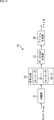
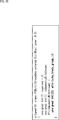
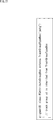
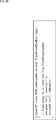
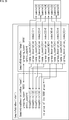
- FIG. 3 is a diagram showing a conventional stream structure. It is a figure explaining PC @ sample newly defined. It is a figure showing an example of PC @ sample.
- FIG. 6 is a diagram illustrating an example of information stored in a header.
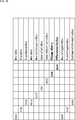
- FIG. 11 is a diagram illustrating an example in which a field for signaling the type of attribute is added. It is a figure showing an example of Attribute
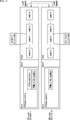
- FIG. 3 is a diagram illustrating an example when a G-PCC stream is stored in an ISOBMFF 1 track. It is a figure showing the definition of codec_specific_parameters. It is a diagram showing the structure of a newly defined PCSampleEntry It is a figure showing an example of PCParamSetBox.
- FIG. 9 is a diagram showing a modification of the ISOBMFF structure stored in 1 track. It is a figure which shows an example which stores geometry @ bitstream and attribute @ bitstream in 2 @ tracks of ISOBMFF. It is a figure showing an example of the syntax of PCMultiStreamBox.
- FIG. 21 is a diagram illustrating a modified example of PCMultiStreamBox. It is a figure showing an example of the syntax of PCAttributeTrackGroupBox.
- FIG. 21 is a diagram illustrating a modified example of PCMultiStreamBox. It is a figure which shows the example which signals geometry @ track and attribute @ track linked by track @ group. It is a figure showing an example of PCStreamGroupBox newly defined.
- FIG. 11 is a diagram illustrating a second example of the ISOBMFF structure stored in 2 track in the second identifiable method.
- FIG. 3 is a diagram illustrating DASH signaling.
- FIG. 3 is a diagram illustrating DASH signaling.
- FIG. 2 is a block diagram illustrating a configuration example of a data generation device.
- FIG. 3 is a block diagram illustrating a configuration example of a data reproduction device.
- FIG. 21 is a block diagram illustrating a configuration example of an embodiment of a computer to which the present technology is applied.
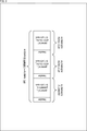
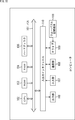
- FIG. 1 shows a stream structure encoded by G-PCC, and such a stream is referred to as G-PCC @ stream (or simply, PC @ stream).
- G-PCC stream is composed of 1 stream and is a sequence of point cloud frames arranged in decoding order.
- the point ⁇ cloud ⁇ frame (hereinafter also referred to as PC ⁇ frame) is Point ⁇ Cloud displayed at the same time.
- PC ⁇ frame is a continuous bitstream composed of a geometry @ bitstream (Geom shown in FIG. 1) indicating three-dimensional information and an attribute @ bitstream (Attr shown in FIG. 1) indicating attribute information such as color and reflection.
- One PC frame has one geometry bitstream and a plurality of attribute bitstreams (two attribute bitstreams in the example of FIG. 1).
- the SPS Sequence Parameter Set
- the GPS stores information necessary for decoding the geometry bitstream
- the APS Attribute Parameter Set
- the client decodes the geometry bitstream and the attribute bitstream in the G-PCC stream using individual decoders.
- the client decodes the geometry bitstream to generate colorless Point Cloud content.
- the client refers to the decoded information of the geometry @ bitstream, decodes the attribute @ bitstream, and adds attributes such as color and reflection based on the information.
- information on the generated geometry bitstream and attribute bitstream is newly generated as identification information, and a file including the generated identification information is generated.
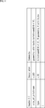
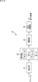
- PC sample a newly defined Point Cloud sample (hereinafter, referred to as a PC sample) will be described as equivalent to a Sample defined by ISOBMFF.
- 1 PC frame is composed of 1 PC sample. That is, the G-PCC stream is composed of a plurality of PC samples, and the 1 PC sample has the same structure as the 1 PC frame shown in FIG. Then, as in the case of the 1 PC frame, the client can construct the 1 PC sample to be displayed as the Point Cloud displayed at the same time by decoding the 1 PC sample.
- PC sample is composed of geometry bitstream and attribute bitstream that constitute Point ⁇ Cloud data displayed at the same time.
- FIG. 3 shows a configuration example in which 1 @ PC @ sample is composed of one geometry @ subsample and two attribute @ subsamples.
- 1 @ PC @ sample has a configuration in which geometry @ subsample, first attribute @ subsample, and second attribute @ subsample are continuously arranged.
- Each subsample has a structure composed of a bitstream corresponding to header information storing information on each bitstream in order to divide each bitstream.
- FIG. 4 shows an example of information stored in the header of FIG.
- size information (size_of_bitstream) indicating the size of the geometry @ bitstream or attribute @ bitstream and type information (type) indicating the type of each bitstream forming the PC @ sample are stored as identification information.
- identification information is information for identifying each bitstream, and is generated for each bitstream.
- SPS, $ GPS, and $ APS not stored in PC $ sample are stored in sample $ entry if they are, for example, ISOBMFF (see FIGS. 9 and 10 described later).
- the client can identify the boundary of each bitstream from the header. Therefore, the client can extract only the geometry bitstream from the PC sample and decode it independently. Similarly, the client can extract and decode only the necessary attribute ⁇ bitstream from PC ⁇ sample. Then, the client can easily input the geometry @ bitstream and the attribute @ bitstream decoded by different decoders to the corresponding decoders.
- the High-level syntax of G-PCC stream may be extended to signal the type of attribute.
- Attribute parameter set can be extended to signal attr_type, as shown in bold in FIG.
- the referenced Attribute parameter set is signaled as an identifier in the attribute bitstream.
- the semantics are the same as those of the attribute_type described above.
- the client can refer to the header, identify the geometry and the attribute, and individually access them. Even in a use case in which only the desired attribute is used, Processing can be performed efficiently.
- ⁇ Second identifiable method> Referring to FIG. 7 to FIG. 24, as a second identifiable method for enabling the client to divide the geometry and the attribute, an extension of the ISOBMFF track storing the sub sample information, the geometry, and the attribute explain.
- FIG. 7 shows an example when the G-PCC stream is stored in the 1 track of ISOBMFF.
- a newly defined PCSampleEntry (see FIG. 9) is stored in the moov of the ISOBMFF, and the PCSampleEntry is composed of a PCParamSetBox shown in FIG.
- subs (SubSampleInformationBox) is stored in the moof of the ISOBMFF. As shown in FIG. 7, the boundaries of the geometry subsample and attribute subsample ⁇ ⁇ ⁇ # 0 to #N in PC sample are signaled using can do. Note that SubSampleInformation will be described with reference to the outline of SubSampleInformationBox shown in FIG. 28 described later.
- codec_specific_parameters which is information of a subsample determined for each codec. That is, when the value of codec_specific_parameters is 0, it indicates that subsample is geometry subsample, and when the value of codec_specific_parameters is 1, it indicates that subsample is attribute subsample.
- subsample information may be provided in units of a continuous attribute @ subsample group.
- codec_specific_parameters may be further extended so that it can signal what attribute / bitstream the subsample is (color attribute, reflection attribute, and the like).
- FIG. 9 shows the structure of PCSampleEntry newly defined in the present disclosure.
- the sample entry of the track of the ISOBMFF storing the G-PCC stream is, for example, 'pcbs'.
- Each parameter set (Sequence Parameter Set, Geometry Parameter Set, and Attribute Parameter Set) as shown in FIG. 10 is stored in the $ PCParamSetBox.
- these parameter $ sets are referenced when decoding the PC $ sample.
- parameter set is not usually changed in PC sample units, so storing it in PCSampleEntry eliminates the need to repeatedly signal the same information for each PC sample, thus reducing file size.
- the storage destination of these parameter @ set includes seq_parameter_set_rbsp (), geometry_parameter_set (), and attribute_parameter_set () in PCParamSetBox.
- the client can identify the boundary between the geometry subsample and the attibute subsample (or the boundary between the attibute subsamples) without parsing the contents of the subsample. That is, the client can extract only the geometry ⁇ bitstream from the PC ⁇ sample and decode it independently by a simplified process of referring to only the signaling of the system layer. Similarly, the client can extract and decode only the necessary attribute ⁇ bitstream from PC ⁇ sample. In addition, the client can easily input the geometry @ bitstream and the attribute @ bitstream to different corresponding decoders.
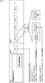
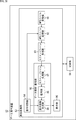
- FIG. 11 shows a configuration of an information processing apparatus that generates a PC stream from Point Cloud data on the server providing the content and executes a file generation process of generating a file in which the PC stream is stored in a file defined by ISOBMFF. It is a block diagram showing an example.
- the information processing apparatus 11 includes a separating unit 21, an encoding unit 22, a PC stream generating unit 23, and a file generating unit 24.
- the separation unit 21 separates the geometry and the attribute from the input Point Cloud data, and supplies them to the encoding unit 22.
- the encoding unit 22 encodes the geometry and the attribute supplied from the separation unit 21 to generate a geometry bitstream and an attribute bitstream. At this time, the encoding unit 22 generates each parameter set (Sequence Parameter Set, Geometry Parameter Set, and Attribute Parameter Set) referred to when decoding the geometry bitstream and the attribute bitstream. For example, the encoding unit 22 encodes geometry by Octree and attribute by Lifting coding or Region Adaptive Haar Transform. At this time, the encoding unit 22 can perform the encoding of the geometry and the encoding of the attribute in parallel by the two encoders 25-1 and 25-2.
- each parameter set Sequence Parameter Set, Geometry Parameter Set, and Attribute Parameter Set
- the PC stream generation unit 23 interleaves the geometry bitstream and the attribute bitstream encoded by the encoding unit 22 in units of a PC frame, and generates a PC sample as shown in FIG. Then, the PC stream generator 23 generates a PC stream composed of a plurality of PC samples and supplies the PC stream to the file generator 24.
- the file generation unit 24 stores the geometry bitstream and the attribute bitstream in the 1 track of the file defined by ISOBMFF, and generates a file. At this time, the file generation unit 24 generates size information indicating the size of the geometry @ bitstream or attribute @ bitstream, and type information indicating the type of each bitstream constituting the PC @ sample, and as the above-described identification information, Store in header.
- the information processing apparatus 11 configured as described above can generate a PC stream from Point Cloud data and output a file in which the PC stream is stored in 1 track.
- the file sample defined by the ISOBMFF is PC @ sample (FIGS. 3 and 7). Reference).
- FIG. 12 is a block diagram showing an example of the configuration of an information processing apparatus that executes a Point @ Cloud reproduction process of generating a display image from a file and reproducing Point @ Cloud data on the client side reproducing the content.
- the information processing device 12 includes an extraction unit 31, a decoding unit 32, a construction unit 33, and a display processing unit 34.
- the extraction unit 31 extracts a geometry bitstream and an attribute bitstream corresponding to a reproduction time from a file based on information (for example, the above-described identification information) signaled in the ISOBMFF Box, and supplies the extracted bitstream and attribute bitstream to the decoding unit 32.
- the extraction unit 31 can identify the geometry and the attribute and extract only the necessary geometry or attribute according to the various use cases described above.
- the extraction unit 31 may extract the geometry @ bitstream and the attribute @ bitstream corresponding to the playback time from the file based on the identification information stored in the header of the subsample, and supply the extracted bitstream and attribute @ bitstream to the decoding unit 32.
- the decoding unit 32 refers to each parameter set, decodes the geometry bitstream and the attribute bitstream supplied from the extraction unit 31, and supplies the geometry and attribute to the construction unit 33. At this time, the decoding unit 32 can perform the decoding of the geometry @ bitstream and the decoding of the attribute @ bitstream by the two decoders 35-1 and 35-2 in parallel and individually.
- the construction unit 33 constructs Point Cloud data using the geometry and attribute supplied from the decoding unit 32.
- the display processing unit 34 renders the Point Cloud data constructed by the construction unit 33 according to the display device of the client, generates a display image, and causes the display device (not shown) to display the image.
- the information processing device 12 configured as described above can reproduce Point @ Cloud data from a file and display a display image in which the Point @ Cloud data is rendered.
- FIG. 13 is a flowchart illustrating a file generation process in which the information processing apparatus 11 of FIG. 11 generates a file from Point Cloud data.
- step S11 the separation unit 21 separates geometry and attribute from the input Point @ Cloud.
- step S12 the encoding unit 22 encodes the geometry and attribute separated by the separation unit 21 in step S11, and generates a geometry bitstream and an attribute bitstream. At this time, the encoding unit 22 generates each parameter $ set.
- step S13 the PC stream generator 23 interleaves the geometry bitstream and the attribute bitstream generated in step S12 in units of a PC frame (PC sample) to generate a PC stream.
- step S14 the file generation unit 24 stores the PC stream generated in step S13 in the ISOBMFF that has signaled the Box including the metadata, and generates a file. Further, the file generation unit 24 generates size information and type information and stores them in the header of the file. At this time, the sample of ISOBMFF is PC sample.
- FIG. 14 is a flowchart illustrating a Point @ Cloud playback process in which the information processing apparatus 12 in FIG. 12 generates and plays back a display image from a file generated in the information processing apparatus 11.
- the extraction unit 31 uses the information (for example, the above-described identification information) signaled in the ISOBMFF Box. Extract the geometrygebitstream and attribute bitstream corresponding to the playback time from the file. Note that the extraction unit 31 may extract a geometry @ bitstream and an attribute @ bitstream corresponding to the reproduction time from the file based on the identification information stored in the header of the subsample.
- step S22 the decoding unit 32 refers to each parameter set and decodes the geometry bitstream and the attribute bitstream extracted in step S21 individually. At this time, the geometry @ bitstream and the attribute @ bitstream are individually decoded by two decoder instances.
- step S23 the construction unit 33 constructs Point @ Cloud data using the geometry and attribute obtained in the decoding in step S22.
- step S24 the display processing unit 34 renders the Point @ Cloud data constructed in step S23 to display a display image according to the display device of the client.
- step S25 the extraction unit 31 determines whether or not it is the end of PC @ stream. If it is not the end of PC @ stream, the process returns to step S21. If it is the end of PC @ stream, the process ends. .
- FIG. 15 shows a first example of the ISOBMFF structure when the geometry @ bitstream and the attribute @ bitstream are stored in the 1 @ track of the ISOBMFF by the second identifiable method.
- the geometry bitstream and the attribute bitstream constituting the 1 PC frame may be stored as 1 sample in the ISOBMFF without using the PC sample.
- geometry subsample and attribute subsample become geometry ⁇ ⁇ sample and attribute sample, respectively.
- ⁇ Geometry @ sample and attribute @ sample (s) constituting 1 @ PC @ frame may be signaled using sample @ group.
- the boundary between geometry @ sample and attribute @ sample may be signaled using sample @ group.
- the sample @ group will be described with reference to a sample @ group outline shown in FIG. 29 described later.
- the G-PCC stream is separated into one geometry bitstream and one attribute bitstream, one geometry bitstream is stored in the ISOBMFF 1 track, and one attribute bitstream is stored in the ISOBMFF 1 track.
- One example of 2 tracks is shown.
- the client can process the track storing only the geometry bitstream and easily decode only the geometry bitstream. Similarly, the client can process a track that stores only one attribute @ bitstream and easily decode only the required attribute @ bitstream. Further, the client can easily input the geometry @ bitstream and the attribute @ bitstream decoded by different decoders to the corresponding decoders.
- TrackAs shown in FIG. 17 the track storing the geometry bitstream is referred to as a geometry ⁇ ⁇ ⁇ track or a main track, and the track storing the attribute bitstream is referred to as an attribute track or a secondary track. Then, the relationship between the tracks is signaled by the track reference and the newly defined PCMultiStreamBox.
- a PCParamSetBox exists only in the main track, and the PCParamSetBox includes Sequence ⁇ Parameter ⁇ Set, Geometry ⁇ Parameter ⁇ Set, and Attribute ⁇ parameter ⁇ set.
- a PCParamSetBox may be present on both the main track and the sub track, in which case, the PCParamSetBox of the main track includes Sequence Parameter Set and Geometry Parameter Set, and the PCParamSetBox of the sub track includes Attribute Parameter Set. Good.
- sample group indicating the boundary of PC frame may be signaled.
- sample group indicating the boundary of PC frame may be signaled.
- a plurality of attribute @ tracks having different bitrates may be associated with one geometry @ track.
- FIG. 18 shows an example of the syntax of PCMultiStreamBox.
- isGeometryStream 1, it indicates that it is geometry @ track; otherwise, it indicates that it is attribute @ track. If it is a geometry @ track, the track_id of the associated attribute @ track is signaled.
- the client can identify which track is the geometry track only by parsing the TrackReferenceBox of an arbitrary 1 track by indicating the track reference.
- the client can then parse the geometryMultitrackBox's PCMultiStreamBox and identify all relevant attributeTracks. That is, the client can identify the entire configuration only by parsing the 2 @ track at the maximum, and can simplify the processing particularly in a case where a plurality of attribute @ tracks are linked.
- attribute @ track may include a plurality of attribute @ bitstreams corresponding to a plurality of types of attributes.
- FIG. 19 shows an example of the ISOBMFF structure when the geometry bitstream and the attribute stream bitstream are individually stored for each 1 track of the ISOBMFF by the second identifiable method.
- a plurality of attribute tracks may be collectively signaled by a track group, and as shown in FIG. 20, attribute_track_group_id may be linked to the attribute track group.
- the track group newly defines a PCAttributeTrackGroupBox as shown in FIG. 21 and the track_group_type is 'pctg'.
- an isInGeometryStream indicating whether the attribute is stored in the same track as the geometry may be added to the PCMultiStreamBox.
- a signal-capable Box can be provided.
- a geometry track and an attribute track linked by a track group may be signaled as shown in FIG.
- track24group newly defines a PCStreamGroupBox, and track_group_type is 'pcgp'.
- FIG. 25 shows a second example of the ISOBMFF structure when the geometry bitstream and the attribute bitstream are stored in the 1BMtrack of ISOBMFF by the second identifiable method.
- the client identifies the geometry and attribute by referring to the information regarding the subsample (SubSampleInformationBox) or the information indicating the relationship between the tracks (PCMultiStreamBox). Can be accessed. Therefore, the client can efficiently perform processing even in a use case in which only a desired geometry or a necessary attribute is used.
- ⁇ Third identifiable method> Referring to FIG. 26 and FIG. 27, as a third identifiable method for enabling the client to divide the geometry and the attribute, the DASH MPD (Media) when the geometry and the attribute are stored in separate tracks.
- the linking method in Presentation Description) will be described.
- the client when the client acquires the DASH distribution content, the client can refer to the PC Component Descriptor and independently acquire the geometry bitstream constituting the PC stream. Similarly, the client can independently decode the attribute @ bitstream. In addition, the client can switch the image quality of the attribute bitstream associated with the geometry bitstream, for example, according to the network bandwidth.
- association from geometry @ representation to attribute @ representation may be performed by Representation @ associationId.
- associationType is “patt”.
- association using the associationId is appropriate.
- the client can identify and independently access the geometry and attribute based on the association in DASH @ MPD. Therefore, the client can efficiently perform processing even in a use case in which only a desired attribute is used. Also, in the third identifiable method, similarly to the second identifiable method, PC @ sample as shown in FIG. 3 is stored as a sample stored in the mdat of ISOBMFF, and the size information And type information are stored.
- FIG. 28 shows an outline of the SubSampleInformationBox.
- a continuous specific byte area in a sample is defined as a sub-sample.
- the definition of sub-sample is determined for each encoding codec. For example, in the case of HEVC, NAL @ unit is a sub-sample.
- the SubSampleInformationBox information can be added for each sub-sample.
- FIG. 29 shows an outline of the Sample @ Group.
- the grouping_type of the Sample To Group Box indicates the grouping_type of the associated Sample Group Description Box.
- sample_count and group_description_index are signaled.
- group_description_index indicates the index of the associated Group @ Entry
- sample_count indicates the number of samples belonging to the Group @ Entry.
- FIG. 30 is a block diagram showing a configuration example of the data generation device.
- the data generation device 51 includes a control unit 61 and a file generation unit 62.
- the file generation unit 62 includes a data input unit 71, a data encoding / generation unit 72, and an MPD file generation unit 73. , A recording unit 74, and an upload unit 75.
- the data encoding / generation unit 72 has a pre-processing unit 76, an encoding unit 77, and a segment file generation unit 78.
- the pre-processing unit 76 corresponds to the above-described separating unit 21 of FIG. 11 and executes a process of separating geometry and attribute from the input Point @ Cloud.
- ⁇ Encoding section 77 corresponds to the encoding section 22 of FIG. 11 described above, and performs processing of encoding the geometry @ bitstream and the attribute @ bitstream and generating each parameter @ set.
- segment file generation unit 78 corresponds to the above-described PC $ stream generation unit 23 and file generation unit 24 in FIG. 11 and executes a process of generating a PC $ stream and generating a file in which the PC $ stream is stored in ISOBMFF. .
- FIG. 31 is a block diagram showing a configuration example of the data reproducing apparatus.
- the data reproduction device 52 includes a control unit 81 and a reproduction processing unit 82.
- the reproduction processing unit 82 includes an MPD file acquisition unit 91, an MPD file processing unit 92, a segment file acquisition unit 93, It comprises a display control unit 94, a data analysis / decoding unit 95, and a display unit 96.
- the data analysis / decoding unit 95 has a segment file processing unit 97, a decoding unit 98, and a display information generation unit 99.
- the segment file processing unit 97 corresponds to the extraction unit 31 in FIG. 12 described above, and executes a process of extracting a geometry @ bitstream and an attribute @ bitstream corresponding to a reproduction time according to a use case.
- ⁇ Decoding section 98 corresponds to decoding section 32 in FIG. 12 described above, and executes a process of individually decoding geometry @ bitstream and attribute @ bitstream.
- the display information generation unit 99 corresponds to the construction unit 33 and the display processing unit 34 in FIG. 12 described above, and constructs Point @ Cloud, renders Point @ Cloud, and displays a display image.
- the client can easily access each of the geometry and the attribute easily by defining the sample structure in which the boundary between the geometry and the attribute is clearly defined. Furthermore, the client can process each track individually by dividing the Point Cloud stream into a geometry bitstream and an attribute bitstream and storing them in 2 tracks of ISOBMFF. In addition, as described above, by defining the association method in DASH ⁇ MPD when the geometry and the attribute are stored in separate tracks, the client can easily access the geometry and the attribute independently. Can be.
- attribute information such as color and reflection is unnecessary, and there is a use case that uses only the three-dimensional shape information of Point Cloud, or when there are multiple attribute information such as color and reflection, for example, for preview, color attribute together with geometry Client processing in use cases such as using only
- FIG. 32 is a block diagram showing a configuration example of an embodiment of a computer on which a program for executing the above-described series of processes is installed.
- the program can be recorded in advance on the hard disk 105 or the ROM 103 as a recording medium built in the computer.
- the program can be stored (recorded) in the removable recording medium 111 driven by the drive 109.
- a removable recording medium 111 can be provided as so-called package software.
- examples of the removable recording medium 111 include a flexible disk, a CD-ROM (Compact Disc Only Memory), an MO (Magneto Optical) disc, a DVD (Digital Versatile Disc), a magnetic disc, and a semiconductor memory.
- the program may be installed in the computer from the removable recording medium 111 as described above, or may be downloaded to the computer via a communication network or a broadcast network and installed in the built-in hard disk 105. That is, for example, the program is wirelessly transferred from a download site to a computer via an artificial satellite for digital satellite broadcasting, or is transmitted to a computer via a network such as a LAN (Local Area Network) or the Internet by wire. be able to.
- LAN Local Area Network
- the computer has a built-in CPU (Central Processing Unit) 102, and an input / output interface 110 is connected to the CPU 102 via a bus 101.
- CPU Central Processing Unit
- the CPU 102 executes a program stored in a ROM (Read Only Memory) 103 when a command is input by a user operating the input unit 107 or the like via the input / output interface 110. .
- the CPU 102 loads a program stored in the hard disk 105 into a random access memory (RAM) 104 and executes the program.
- RAM random access memory
- the CPU 102 performs the processing according to the above-described flowchart or the processing performed by the configuration of the above-described block diagram. Then, the CPU 102 causes the processing result to be output from the output unit 106 or transmitted from the communication unit 108 via the input / output interface 110 as needed, and further recorded on the hard disk 105, for example.
- the input unit 107 includes a keyboard, a mouse, a microphone, and the like.
- the output unit 106 includes an LCD (Liquid Crystal Display), a speaker, and the like.
- the processing performed by the computer according to the program does not necessarily need to be performed in chronological order in the order described in the flowchart. That is, the processing performed by the computer in accordance with the program includes processing executed in parallel or individually (for example, parallel processing or processing by an object).
- the program may be processed by a single computer (processor) or may be processed in a distributed manner by a plurality of computers. Further, the program may be transferred to a remote computer and executed.
- a system means a set of a plurality of components (devices, modules (parts), etc.), and it does not matter whether all components are in the same housing. Therefore, a plurality of devices housed in separate housings and connected via a network, and one device housing a plurality of modules in one housing are all systems. .
- the configuration described as one device (or processing unit) may be divided and configured as a plurality of devices (or processing units).
- the configuration described above as a plurality of devices (or processing units) may be combined and configured as one device (or processing unit).
- a configuration other than those described above may be added to the configuration of each device (or each processing unit).
- a part of the configuration of a certain device (or processing unit) may be included in the configuration of another device (or other processing unit).
- the present technology can adopt a configuration of cloud computing in which one function is shared by a plurality of devices via a network and processed jointly.
- the above-described program can be executed in any device.
- the device only has to have necessary functions (functional blocks and the like) and can obtain necessary information.
- each step described in the above-described flowchart can be executed by a single device, or can be shared and executed by a plurality of devices.
- the plurality of processes included in the one step can be executed by one device or can be shared and executed by a plurality of devices.
- a plurality of processes included in one step can be executed as a plurality of steps.
- the processing described as a plurality of steps can be collectively executed as one step.
- the program executed by the computer may be configured so that the processing of the steps for describing the program is executed in chronological order according to the order described in this specification, or may be executed in parallel or by calling. It may be executed individually at a necessary timing such as time. That is, as long as no contradiction occurs, the processing of each step may be performed in an order different from the order described above. Further, the processing of the steps for describing the program may be executed in parallel with the processing of another program, or may be executed in combination with the processing of another program.
- the present technology can also have the following configurations.
- a stream of shape information representing the shape of the three-dimensional structure and identification information relating to a stream of attribute information representing the attribute of the three-dimensional structure are generated for each of the streams,
- An information processing apparatus comprising: a file generation unit that generates a file including a plurality of pieces of the generated identification information.
- the identification information includes size information indicating a size of each stream, and type information indicating a type of each stream.
- the file generation unit generates the file with a sample structure in which a boundary between the shape information and the attribute information is specified.
- the file generation unit indicates, in the header of each of the shape information and the attribute information of the subsamples constituting the file, size information indicating a size of the subsample as the identification information, and a type of the subsample.
- the information processing device according to any one of (1) to (3), wherein the type information is stored.
- the file generation unit stores the stream of the shape information and the stream of the attribute information in one track of an ISO Base Media File Format (ISOBMFF), and uses the information on the sub-samples constituting the file to store the shape.
- ISOBMFF ISO Base Media File Format
- the file generation unit in the header of each of the shape information and the attribute information of the sub-sample stored in mdat of ISOBMFF, as the identification information, size information indicating the size of the sub-sample, and the The information processing device according to (5), which stores type information indicating a type.
- the file generation unit separates the stream of the position and shape information and the stream of the attribute information, stores them separately for each track of ISOBMFF, and uses the information indicating the relationship between the tracks to store the information.
- the information processing device according to any one of (1) to (3), which signals position and shape information and the attribute information.
- the file generating unit separates the stream of the shape information and the stream of the attribute information, stores them separately for each track of ISOBMFF, and generates a DASH (Dynamic Adaptive Streaming over HTTP) MPD (Media Presentation).
- the information processing apparatus according to any one of (1) to (3), wherein the shape information and the attribute information are signaled using (Description).
- the file generation unit is stored in the mdat of ISOBMFF, in the header of each of the shape information and the attribute information of the subsample constituting the file, as the identification information, size information indicating the size of the subsample,
- the information processing apparatus according to (8), wherein type information indicating a type of the subsample is stored.
- the information processing device is Generating, for each of the streams, a stream of shape information representing the shape of the three-dimensional structure and a stream of attribute information representing the attribute of the three-dimensional structure, from the 3D data representing the three-dimensional structure; When, Generating a file including the generated plurality of pieces of identification information.
- (11) In the computer of the information processing device, Generating, for each of the streams, a stream of shape information representing the shape of the three-dimensional structure and a stream of attribute information representing the attribute of the three-dimensional structure, from the 3D data representing the three-dimensional structure; When, Generating a file including the generated plurality of pieces of identification information.
- a stream of shape information representing the shape of the three-dimensional structure and identification information relating to a stream of attribute information representing the attribute of the three-dimensional structure are generated for each of the streams.
- the information processing device is From the 3D data representing the three-dimensional structure, a stream of shape information representing the shape of the three-dimensional structure and identification information relating to a stream of attribute information representing the attribute of the three-dimensional structure are generated for each of the streams.
- 11 and 12 information processing device ⁇ 21 ⁇ separation unit, ⁇ 22 ⁇ encoding unit, ⁇ 23 ⁇ PC stream generation unit, ⁇ 24 ⁇ file generation unit, ⁇ 31 ⁇ extraction unit, ⁇ 32 ⁇ decoding unit, ⁇ 33 ⁇ construction unit, ⁇ 34 ⁇ display processing unit, ⁇ 51 ⁇ data generation device, # 52 Data reproducing device, ⁇ 61 ⁇ control unit, ⁇ 62 ⁇ file generation unit, ⁇ 71 ⁇ data input unit, ⁇ 72 ⁇ data encoding / generation unit, ⁇ 73 ⁇ MPD file generation unit, ⁇ 74 ⁇ recording unit, ⁇ 75 ⁇ upload unit, ⁇ 76 ⁇ preprocessing unit, ⁇ 77 ⁇ encoding unit, 78 segment file generation unit, 81 control unit, 82 playback processing unit, 91 MPD file acquisition unit, 92 MPD file processing unit, 93 segment file acquisition unit, 94 display control unit, 95 data analysis / decoding unit, 96 display unit, 97 Segment phi Processing unit, ⁇ 98 ⁇ decoding unit, ⁇ 99 ⁇ display information generation unit
Abstract
The present invention relates to an information processing device, an information processing method and a program which enable efficient processing in a client. From 3D data representing a three-dimensional structure, identification information relating to a stream of shape information representing shapes of the three-dimensional structure and a stream of attribute information representing attributes of the three-dimensional structure is generated for each stream, a file containing the multiple sets of generated identification information is generated, and this file is generated with a sample structure that clearly shows boundaries of the shape information and the attribute information. The present invention can be applied, for example, to a data generation device which generates data for distributing a Point Cloud, or to a data playback device for playing a Point Cloud.
Description
本開示は、情報処理装置および情報処理方法、並びにプログラムに関し、特に、クライアントにおける処理を効率良く行うことができるようにした情報処理装置および情報処理方法、並びにプログラムに関する。
The present disclosure relates to an information processing apparatus, an information processing method, and a program, and more particularly, to an information processing apparatus, an information processing method, and a program capable of efficiently performing processing in a client.
従来、非特許文献1で開示されているように、3次元空間上に形状情報および属性情報(特に色情報)を同時に持った点の集合であるPoint Cloudの圧縮方法が規定されている。
Conventionally, as disclosed in Non-Patent Document 1, a compression method of Point @ Cloud, which is a set of points simultaneously having shape information and attribute information (especially color information) in a three-dimensional space, is defined.
また、Point Cloudの圧縮方法の一つとして、Point Cloudデータを、3次元形状を示すgeometryと、属性情報として色や反射情報などを示すattributeとに分離して、それらを符号化する方法がある。この方法は、G-PCC(Geometry based Point Cloud Coding)と称されている。
Also, as one of the compression methods of Point @ Cloud, there is a method of separating Point @ Cloud data into a geometry indicating a three-dimensional shape and an attribute indicating color and reflection information as attribute information and encoding them. . This method is called G-PCC (Geometry-based-Point-Cloud-Coding).
そして、この符号化によって生成されたG-PCCのストリームを、ダウンロード再生したり、over IP(Internet Protocol) networkで配信したりするユースケースが期待されている。そこで、非特許文献2で開示されているように、既存の配信プラットフォームへのインパクトを抑制し、早期のサービス実現を目指すべく、MPEG(Moving Picture Experts Group)において、既存の枠組みであるISOBMFF/DASH(ISO Base Media File Format / Dynamic Adaptive Streaming over HTTP)による配信技術についての検討が開始された。
Use cases are expected where the G-PCC stream generated by this encoding is downloaded and played back or distributed over over IP (Internet Protocol) network. Therefore, as disclosed in Non-Patent Document 2, in order to suppress the impact on existing distribution platforms and achieve early service, MPEG (Moving Picture Experts Group) uses the existing framework ISOBMFF / DASH. A study on distribution technology using (ISO / Base / Media / File / Format / Dynamic / Adaptive / Streaming / over / HTTP) has started.
ところで、従来、生成されたG-PCCのストリームは、連続する1つのストリームであり、クライアントが、geometryおよびattributeそれぞれに独立してアクセスすることができない構造となっていた。そのため、例えば、geometryだけを用いるユースケースや、複数のattributeのうちの1つだけを用いるユースケースなどであっても、クライアントが、それらに個別にアクセスして取得することができない。従って、G-PCCのストリームを構成するgeometryおよびattributeの全てを取得した上で処理を行う必要があり、クライアントにおいて処理のオーバヘッドが発生し、処理を効率良く行うことは困難であった。
By the way, conventionally, the generated G-PCC stream is one continuous stream, and has a structure in which the client cannot independently access the geometry and the attribute. Therefore, for example, even in a use case using only the geometry or a use case using only one of the plurality of attributes, the client cannot individually access and acquire them. Therefore, it is necessary to perform the processing after acquiring all of the geometry and attribute constituting the G-PCC stream, and processing overhead occurs in the client, and it has been difficult to perform the processing efficiently.
本開示は、このような状況に鑑みてなされたものであり、クライアントにおける処理を効率良く行うことができるようにするものである。
(4) The present disclosure has been made in view of such a situation, and aims to enable a client to perform processing efficiently.
本開示の第1の側面の情報処理装置は、3次元構造を表す3Dデータから、前記3次元構造の形状を表す形状情報のストリーム、および、前記3次元構造の属性を表す属性情報のストリームに関する識別情報を、それぞれの前記ストリームごとに生成し、生成された複数の前記識別情報を含むファイルを生成するファイル生成部を備える。
An information processing device according to a first aspect of the present disclosure relates to a stream of shape information representing a shape of the three-dimensional structure and a stream of attribute information representing an attribute of the three-dimensional structure from 3D data representing the three-dimensional structure. A file generation unit that generates identification information for each of the streams and generates a file including the generated plurality of pieces of identification information.
本開示の第1の側面の情報処理方法またはプログラムは、3次元構造を表す3Dデータから、前記3次元構造の形状を表す形状情報のストリーム、および、前記3次元構造の属性を表す属性情報のストリームに関する識別情報を、それぞれの前記ストリームごとに生成することと、生成された複数の前記識別情報を含むファイルを生成することとを含む。
An information processing method or a program according to a first aspect of the present disclosure provides a stream of shape information representing a shape of the three-dimensional structure from 3D data representing the three-dimensional structure, and attribute information representing an attribute of the three-dimensional structure. The method includes generating identification information on a stream for each of the streams, and generating a file including the generated plurality of identification information.
本開示の第1の側面においては、3次元構造を表す3Dデータから、3次元構造の形状を表す形状情報のストリーム、および、3次元構造の属性を表す属性情報のストリームに関する識別情報が、それぞれの前記ストリームごとに生成され、その生成された複数の識別情報を含むファイルが生成される。
According to the first aspect of the present disclosure, identification information relating to a stream of shape information representing a shape of a three-dimensional structure and a stream of attribute information representing an attribute of the three-dimensional structure are respectively obtained from 3D data representing a three-dimensional structure. Is generated for each of the streams, and a file including the generated plurality of pieces of identification information is generated.
本開示の第2の側面の情報処理装置は、3次元構造を表す3Dデータから、前記3次元構造の形状を表す形状情報のストリーム、および、前記3次元構造の属性を表す属性情報のストリームに関する識別情報が、それぞれの前記ストリームごとに生成されて含まれるファイルから、ユースケースに応じて、前記識別情報をもとに、前記形状情報および前記属性情報を識別して抽出する抽出部と、前記抽出部により抽出された前記形状情報または前記属性情報を用いて、前記3次元構造を構築する構築部とを備える。
An information processing apparatus according to a second aspect of the present disclosure relates to a stream of shape information representing a shape of the three-dimensional structure and a stream of attribute information representing an attribute of the three-dimensional structure from 3D data representing the three-dimensional structure. An identification unit configured to identify and extract the shape information and the attribute information based on the identification information, based on the identification information, from a file generated and included for each of the streams, A construction unit configured to construct the three-dimensional structure using the shape information or the attribute information extracted by the extraction unit.
本開示の第2の側面の情報処理方法またはプログラムは、3次元構造を表す3Dデータから、前記3次元構造の形状を表す形状情報のストリーム、および、前記3次元構造の属性を表す属性情報のストリームに関する識別情報が、それぞれの前記ストリームごとに生成されて含まれるファイルから、ユースケースに応じて、前記識別情報をもとに、前記形状情報および前記属性情報を識別して抽出することと、その抽出された前記形状情報または前記属性情報を用いて、前記3次元構造を構築することとを含む。
An information processing method or a program according to a second aspect of the present disclosure provides a stream of shape information representing the shape of the three-dimensional structure from 3D data representing the three-dimensional structure, and attribute information representing an attribute of the three-dimensional structure. Identification information about the stream, from the file generated and included for each of the streams, depending on the use case, based on the identification information, identifying and extracting the shape information and the attribute information, Constructing the three-dimensional structure using the extracted shape information or attribute information.
本開示の第1の側面においては、3次元構造を表す3Dデータから、3次元構造の形状を表す形状情報のストリーム、および、3次元構造の属性を表す属性情報のストリームに関する識別情報が、それぞれのストリームごとに生成されて含まれるファイルから、ユースケースに応じて、識別情報をもとに、形状情報および属性情報が識別して抽出され、その抽出された形状情報または属性情報を用いて、3次元構造が構築される。
According to the first aspect of the present disclosure, identification information relating to a stream of shape information representing a shape of a three-dimensional structure and a stream of attribute information representing an attribute of the three-dimensional structure are respectively obtained from 3D data representing a three-dimensional structure. From the files generated and included for each stream, the shape information and the attribute information are identified and extracted based on the identification information according to the use case, and using the extracted shape information or attribute information, A three-dimensional structure is constructed.
以下、本技術を適用した具体的な実施の形態について、図面を参照しながら詳細に説明する。
Hereinafter, specific embodiments to which the present technology is applied will be described in detail with reference to the drawings.
<従来のstream構造>
本技術を適用したstream構造について説明する前に、図1を参照して、従来のstream構造について説明する。 <Conventional stream structure>
Before describing the stream structure to which the present technology is applied, a conventional stream structure will be described with reference to FIG.
本技術を適用したstream構造について説明する前に、図1を参照して、従来のstream構造について説明する。 <Conventional stream structure>
Before describing the stream structure to which the present technology is applied, a conventional stream structure will be described with reference to FIG.
図1には、G-PCCで符号化されたstream構造が示されており、このようなstreamは、G-PCC stream(または、単にPC stream)と称される。
FIG. 1 shows a stream structure encoded by G-PCC, and such a stream is referred to as G-PCC @ stream (or simply, PC @ stream).
例えば、G-PCC streamは、1 streamで構成されており、デコード順に並んだpoint cloud frameの連続である。ここで、point cloud frame(以下、PC frameとも記載する)とは、同時刻に表示されるPoint Cloudのことである。PC frameは、3次元情報を示すgeometry bitstream(図1に示すGeom)と、色や反射といった属性情報を示すattribute bitstream(図1に示すAttr)から構成される連続する1つのbitstreamである。
For example, G-PCC stream is composed of 1 stream and is a sequence of point cloud frames arranged in decoding order. Here, the point \ cloud \ frame (hereinafter also referred to as PC \ frame) is Point \ Cloud displayed at the same time. PC @ frame is a continuous bitstream composed of a geometry @ bitstream (Geom shown in FIG. 1) indicating three-dimensional information and an attribute @ bitstream (Attr shown in FIG. 1) indicating attribute information such as color and reflection.
なお、1つのPC frameは、1つのgeometry bitstreamと複数のattribute bitstream(図1の例では、2つのattribute bitstream)とを有する。また、SPS(Sequence Parameter Set)には、geometry bitstreamおよびattribute bitstreamのデコードに必要な共通情報として、G-PCC streamのシーケンスごとのメタ情報が格納されている。そして、GPS(Geometry Parameter Set)には、geometry bitstreamのデコードに必要な情報が格納されており、APS(Attribute Parameter Set)には、attribute bitstreamのデコードに必要な情報が格納されている。
One PC frame has one geometry bitstream and a plurality of attribute bitstreams (two attribute bitstreams in the example of FIG. 1). The SPS (Sequence Parameter Set) stores meta information for each G-PCC stream as common information necessary for decoding the geometry bitstream and the attribute bitstream. The GPS (Geometry Parameter Set) stores information necessary for decoding the geometry bitstream, and the APS (Attribute Parameter Set) stores information necessary for decoding the attribute bitstream.
そして、クライアントは、G-PCC stream内のgeometry bitstreamおよびattribute bitstreamを、それぞれ個別のデコーダでデコードする。まず、クライアントは、geometry bitstreamをデコードし、色のないPoint Cloudコンテンツを生成する。その後、クライアントは、デコードされたgeometry bitstreamの情報を参照した上でattribute bitstreamをデコードし、その情報に基づいて色や反射といった属性を付加する。
Then, the client decodes the geometry bitstream and the attribute bitstream in the G-PCC stream using individual decoders. First, the client decodes the geometry bitstream to generate colorless Point Cloud content. Thereafter, the client refers to the decoded information of the geometry @ bitstream, decodes the attribute @ bitstream, and adds attributes such as color and reflection based on the information.
ところで、G-PCC streamのユースケースとして、色付きのPoint Cloudデータを再生するという一般的なユースケースの他に、色や反射といった属性情報が不要で、Point Cloudデータの3次元形状情報だけを利用するユースケースがある。例えば、LiDAR(Light Detection and Ranging)およびカメラで取得した色付きの地図情報をPoint Cloudデータとして保持し、その中の地形情報(即ち、3次元形状情報)のみを抽出して自動車の運転制御などに利用するユースケースが考えられる。
By the way, as the use case of G-PCC の 他 stream, besides the general use case of playing colored Point Cloud data, attribute information such as color and reflection is not required, and only the three-dimensional shape information of Point Cloud data is used. There are use cases to do. For example, LiDAR (Light Detection and Ranging) and colored map information obtained by a camera are stored as Point Cloud data, and only terrain information (that is, three-dimensional shape information) is extracted and used for driving control of automobiles. Use cases to be used are conceivable.
また、色や反射といった属性情報が複数ついている場合には、例えば、プレビュー用にはgeometryとともに、反射の属性を利用せずに、色の属性だけ利用したいユースケースがある。また、複数の色属性がある場合には、それらのうちの1つの色属性だけ利用するなど、1つのattributeのみ抽出して利用したいユースケースもある。
In addition, when there is a plurality of pieces of attribute information such as color and reflection, for example, there is a use case where it is desired to use only the color attribute without using the reflection attribute together with the geometry for preview. Further, when there are a plurality of color attributes, there is a use case in which only one attribute is desired to be extracted and used, such as using only one of the color attributes.
しかしながら、例えば、G-PCC stream構造においては、attribute付きのPC frameをデコードするためには、geometryと複数のattributeを含めて1つのbitstreamとして扱う必要があり、明示的な境界情報も存在しない。このため、これらのユースケースにおいても、クライアントは、PC frameを構成するgeometryおよびattributeを全て取得した上で、ストリームの先頭から順に全てをデコードしなくてはならならず、利用しないattribute bitstreamをデコードすることになるため、処理効率が悪くなってしまう。
However, for example, in the G-PCC stream structure, in order to decode a PC frame with an attribute, it is necessary to treat it as one bitstream including a geometry and a plurality of attributes, and there is no explicit boundary information. Therefore, even in these use cases, the client must acquire all the geometry and attributes that make up the PC frame and decode all of them in order from the beginning of the stream. Processing efficiency is reduced.
そこで、本開示では、このように効率が悪くなることを解決するため、生成されるgeometry bitstreamおよびattribute bitstreamに関する情報を、新たに識別情報として生成し、その生成された識別情報を含むファイルを生成する手法を提案する。以下で説明する具体的な実施の形態は、このようなユースケースであっても、geometryおよびattributeをそれぞれに独立してアクセス可能とすることで、クライアントにおける処理を効率良く行うことができるようにするものである。
Therefore, in the present disclosure, in order to solve such inefficiency, information on the generated geometry bitstream and attribute bitstream is newly generated as identification information, and a file including the generated identification information is generated. We propose a method to In the specific embodiment described below, even in such a use case, by enabling the geometry and the attribute to be accessed independently of each other, the processing in the client can be efficiently performed. Is what you do.
<PC sampleの定義>
図2を参照して、ISOBMFFで定義されるSampleに相当するものとして、新たに定義するPoint Cloud sample(以下、PC sampleと称する)について説明する。 <Definition of PC sample>
With reference to FIG. 2, a newly defined Point Cloud sample (hereinafter, referred to as a PC sample) will be described as equivalent to a Sample defined by ISOBMFF.
図2を参照して、ISOBMFFで定義されるSampleに相当するものとして、新たに定義するPoint Cloud sample(以下、PC sampleと称する)について説明する。 <Definition of PC sample>
With reference to FIG. 2, a newly defined Point Cloud sample (hereinafter, referred to as a PC sample) will be described as equivalent to a Sample defined by ISOBMFF.
例えば、同時刻に表示されるPoint Cloudデータを構成する単位であるPC frameについて、1 PC frameは1 PC sampleから構成されると定義する。つまり、G-PCC streamは、複数のPC sampleから構成され、1 PC sampleは、図2に示す1 PC frameと同様な構造を有する。そして、クライアントは、1 PC frameと同様に、1 PC sampleをデコードすることで、同時刻に表示されるPoint Cloudとして構築することが可能となる。
{For example, for a PC frame that constitutes Point Cloud data displayed at the same time, it is defined that 1 PC frame is composed of 1 PC sample. That is, the G-PCC stream is composed of a plurality of PC samples, and the 1 PC sample has the same structure as the 1 PC frame shown in FIG. Then, as in the case of the 1 PC frame, the client can construct the 1 PC sample to be displayed as the Point Cloud displayed at the same time by decoding the 1 PC sample.
このように、PC sampleは、同時刻に表示されるPoint Cloudデータを構成するgeometry bitstreamおよびattribute bitstreamから構成される。
Thus, PC sample is composed of geometry bitstream and attribute bitstream that constitute Point を Cloud data displayed at the same time.
<第1の識別可能方法>
図3乃至図6を参照して、クライアントにおいてgeometryおよびattributeを分割するための識別を可能にする第1の識別可能方法として、geometryおよびattributeの境界を明示したsample構造について説明する。 <First identifiable method>
With reference to FIGS. 3 to 6, a sample structure in which the boundary between the geometry and the attribute is specified will be described as a first identifiable method for enabling the client to divide the geometry and the attribute.
図3には、1 PC sampleが、1つのgeometry subsampleと2つのattribute subsampleによって構成される構成例が示されている。
FIG. 3 shows a configuration example in which 1 @ PC @ sample is composed of one geometry @ subsample and two attribute @ subsamples.
図3に示すように、1 PC sampleは、geometry subsample、1つ目のattribute subsample、および、2つ目のattribute subsampleが連続的に配置された構成となっている。そして、各subsampleは、各bitstreamを分割するため各bitstreamに関する情報を格納したheader情報と対応するbitstreamから構成される構造となっている。
As shown in FIG. 3, 1 @ PC @ sample has a configuration in which geometry @ subsample, first attribute @ subsample, and second attribute @ subsample are continuously arranged. Each subsample has a structure composed of a bitstream corresponding to header information storing information on each bitstream in order to divide each bitstream.
図4には、図3のheaderに格納される情報の一例が示されている。
FIG. 4 shows an example of information stored in the header of FIG.
図4に示すように、headerには、geometry bitstreamまたはattribute bitstreamのサイズを示すサイズ情報(size_of_bitstream)と、PC sampleを構成する各bitstreamのタイプを示すタイプ情報(type)とが識別情報として格納される。例えば、bitstreamのタイプを示す情報が0である場合、geometry bitstreamであることを示し、bitstreamのタイプを示す情報が1である場合、attribute bitstreamであることを示す。この識別情報は、各bitstreamを識別するための情報であり、bitstreamごとに生成される。
As shown in FIG. 4, in the header, size information (size_of_bitstream) indicating the size of the geometry @ bitstream or attribute @ bitstream and type information (type) indicating the type of each bitstream forming the PC @ sample are stored as identification information. You. For example, if the information indicating the type of the bitstream is 0, it indicates that the geometry is a bitstream, and if the information indicating the type of the bitstream is 1, it indicates that the attribute is a bitstream. This identification information is information for identifying each bitstream, and is generated for each bitstream.
なお、PC sampleに格納されないSPS, GPS, APSは、例えば、ISOBMFFであればsample entryに格納(後述する図9および図10参照)される。
Note that SPS, $ GPS, and $ APS not stored in PC $ sample are stored in sample $ entry if they are, for example, ISOBMFF (see FIGS. 9 and 10 described later).
そして、これらのシグナリングによれば、クライアントは、headerから各bitstreamの境界を識別可能である。従って、クライアントは、PC sampleからgeometry bitstreamのみを抽出し、独立してデコードすることができる。同様に、クライアントは、PC sampleから必要なattribute bitstreamのみを抽出してデコードすることができる。そして、クライアントは、異なるデコーダでデコードされるgeometry bitstreamおよびattribute bitstreamを、それぞれ対応するデコーダに容易に入力することができる。
According to these signaling, the client can identify the boundary of each bitstream from the header. Therefore, the client can extract only the geometry bitstream from the PC sample and decode it independently. Similarly, the client can extract and decode only the necessary attribute \ bitstream from PC \ sample. Then, the client can easily input the geometry @ bitstream and the attribute @ bitstream decoded by different decoders to the corresponding decoders.
さらに、headerを拡張し、図5において太字で示すように、type=1(即ち、bitstreamがattribute bitstream)である場合において、その属性の種類をシグナルするフィールド(attribute_type)を追加してもよい。例えば、attributeの種類をシグナルするフィールドが0である場合、attributeの種類が色であることを示し、attributeの種類をシグナルするフィールドが1である場合、attributeの種類が反射であることを示す。また、attributeの種類をシグナルするフィールドを用いて、その他の種類を示すこともできる。
(5) Further, as shown in bold in FIG. 5, when the header is extended, a field (attribute_type) for signaling the type of the attribute may be added when type = 1 (that is, the bitstream is attributeatbitstream). For example, if the field that signals the type of attribute is 0, it indicates that the type of attribute is color, and if the field that signals the type of attribute is 1, it indicates that the type of attribute is reflection. Other types can also be indicated using a field that signals the type of attribute.
また、G-PCC streamのHigh level syntaxを拡張し、属性の種類をシグナルしてもよい。
Alternatively, the High-level syntax of G-PCC stream may be extended to signal the type of attribute.
例えば、Attribute parameter setを拡張し、図6において太字で示すように、attr_typeをシグナルすることができる。また、参照されるAttribute parameter setは、attribute bitstream内で識別子としてシグナルされる。なお、セマンティクスは、上述したattribute_typeと同様である。
For example, Attribute parameter set can be extended to signal attr_type, as shown in bold in FIG. Also, the referenced Attribute parameter set is signaled as an identifier in the attribute bitstream. The semantics are the same as those of the attribute_type described above.
以上のような第1の識別可能方法により、クライアントは、headerを参照して、geometryおよびattributeを識別して個別にアクセスすることができ、所望のattributeのみを利用するようなユースケースにおいても、効率良く処理を行うことができる。
According to the first identifiable method as described above, the client can refer to the header, identify the geometry and the attribute, and individually access them. Even in a use case in which only the desired attribute is used, Processing can be performed efficiently.
<第2の識別可能方法>
図7乃至図24を参照して、クライアントにおいてgeometryおよびattributeを分割するための識別を可能にする第2の識別可能方法として、sub sample information、geometry、およびattributeを格納するISOBMFFのtrackの拡張について説明する。 <Second identifiable method>
Referring to FIG. 7 to FIG. 24, as a second identifiable method for enabling the client to divide the geometry and the attribute, an extension of the ISOBMFF track storing the sub sample information, the geometry, and the attribute explain.
まず、図7乃至図15を参照し、第2の識別可能方法において、G-PCC streamのgeometry bitstreamおよびattribute bitstreamを、ISOBMFFの1 tracksに格納するケースについて説明する。
First, with reference to FIGS. 7 to 15, a case where the geometry-bitstream and the attribute-bitstream of the G-PCC stream are stored in 1-tracks of the ISOBMFF in the second identifiable method will be described.
図7には、G-PCC streamをISOBMFFの1 trackに格納する際の一例が示されている。
FIG. 7 shows an example when the G-PCC stream is stored in the 1 track of ISOBMFF.
例えば、ISOBMFFのmoovには、新たに定義するPCSampleEntry(図9参照)が格納され、PCSampleEntryは、図10に示すPCParamSetBoxからなる。
For example, a newly defined PCSampleEntry (see FIG. 9) is stored in the moov of the ISOBMFF, and the PCSampleEntry is composed of a PCParamSetBox shown in FIG.
また、ISOBMFFのmoofには、subs(SubSampleInformationBox)が格納され、図7に示すように、SubSampleInformationBoxを利用して、PC sample内のgeometry subsample、および、attribute subsample #0乃至#Nそれぞれの境界をシグナルすることができる。なお、SubSampleInformationについては、後述の図28に示すSubSampleInformationBoxの概要を参照して説明する。
In addition, subs (SubSampleInformationBox) is stored in the moof of the ISOBMFF. As shown in FIG. 7, the boundaries of the geometry subsample and attribute subsample お よ び # 0 to #N in PC sample are signaled using can do. Note that SubSampleInformation will be described with reference to the outline of SubSampleInformationBox shown in FIG. 28 described later.
そして、ISOBMFFのmdatに格納されるsampleとして、図3に示したようなPC sampleが格納され、そのヘッダに、サイズ情報およびタイプ情報が格納されている。
{> Then, as the sample stored in the mdat of the ISOBMFF, the PC $ sample as shown in FIG. 3 is stored, and the size information and the type information are stored in the header thereof.
ここで、図8に示すように、SubSampleInformationBoxにおいて、コーデックごとに決まるsubsampleの情報であるcodec_specific_parametersが定義される。即ち、codec_specific_parametersの値が0であるとき、subsampleはgeometry subsampleであることを示し、codec_specific_parametersの値が1であるとき、subsampleはattribute subsampleであることを示す。
Here, as shown in FIG. 8, in the SubSampleInformationBox, codec_specific_parameters, which is information of a subsample determined for each codec, is defined. That is, when the value of codec_specific_parameters is 0, it indicates that subsample is geometry subsample, and when the value of codec_specific_parameters is 1, it indicates that subsample is attribute subsample.
なお、subsample informationは、連続するattribute subsample群の単位で提供されてもよい。また、codec_specific_parametersをさらに拡張し、subsampleが何のattribute bitstreamなのか(色のattributeや、反射のattributeなど)をシグナルできるようにしてもよい。
Note that the subsample information may be provided in units of a continuous attribute @ subsample group. Further, the codec_specific_parameters may be further extended so that it can signal what attribute / bitstream the subsample is (color attribute, reflection attribute, and the like).
図9には、本開示で新たに定義するPCSampleEntryの構造が示されている。
FIG. 9 shows the structure of PCSampleEntry newly defined in the present disclosure.
図9に示す構成において、G-PCC streamを格納するISOBMFFのtrackのsample entryは、例えば、’pcbs’となる。
In the configuration shown in FIG. 9, the sample entry of the track of the ISOBMFF storing the G-PCC stream is, for example, 'pcbs'.
PCParamSetBoxには、図10に示すような各parameter set(Sequence Parameter Set、Geometry Parameter Set、およびAttribute Parameter Set)が格納される。例えば、これらのparameter setは、PC sampleをデコードする際に参照される。また、parameter setは、通常、PC sample単位で変更される情報ではないため、PCSampleEntryに格納することで、PC sampleごとに同じ情報を繰り返しシグナルする必要が不要となり、ファイルサイズを削減することができる。なお、これらのparameter setの格納先としては、PCParamSetBoxにおけるseq_parameter_set_rbsp(),geometry_parameter_set()、およびattribute_parameter_set()が挙げられる。
Each parameter set (Sequence Parameter Set, Geometry Parameter Set, and Attribute Parameter Set) as shown in FIG. 10 is stored in the $ PCParamSetBox. For example, these parameter $ sets are referenced when decoding the PC $ sample. Also, parameter set is not usually changed in PC sample units, so storing it in PCSampleEntry eliminates the need to repeatedly signal the same information for each PC sample, thus reducing file size. . The storage destination of these parameter @ set includes seq_parameter_set_rbsp (), geometry_parameter_set (), and attribute_parameter_set () in PCParamSetBox.
これらのシグナリングによれば、クライアントは、subsampleの中身をパースすることなく、geometryのsubsampleとattibuteのsubsampleとの境界(または、attibuteのsubsampleどうしの境界)を識別可能となる。つまり、クライアントは、システムレイヤのシグナリングのみを参照するという簡略化された処理で、PC sampleからgeometry bitstreamのみを抽出し、独立してデコードすることができる。同様に、クライアントは、PC sampleから必要なattribute bitstreamのみを抽出してデコードすることができる。また、クライアントは、geometry bitstreamおよびattribute bitstreamを、それぞれ対応する異なるデコーダに容易に入力することができる。
According to these signalings, the client can identify the boundary between the geometry subsample and the attibute subsample (or the boundary between the attibute subsamples) without parsing the contents of the subsample. That is, the client can extract only the geometry \ bitstream from the PC \ sample and decode it independently by a simplified process of referring to only the signaling of the system layer. Similarly, the client can extract and decode only the necessary attribute \ bitstream from PC \ sample. In addition, the client can easily input the geometry @ bitstream and the attribute @ bitstream to different corresponding decoders.
<情報処理装置の構成例>
図11は、コンテンツを提供するサーバ側で、Point CloudデータからPC streamを生成し、そのPC streamをISOBMFFで定義されるファイルに格納したファイルを生成するファイル生成処理を実行する情報処理装置の構成例を示すブロック図である。 <Configuration example of information processing device>
FIG. 11 shows a configuration of an information processing apparatus that generates a PC stream from Point Cloud data on the server providing the content and executes a file generation process of generating a file in which the PC stream is stored in a file defined by ISOBMFF. It is a block diagram showing an example.
図11に示すように、情報処理装置11は、分離部21、符号化部22、PC stream生成部23、およびファイル生成部24を備えて構成される。
As shown in FIG. 11, the information processing apparatus 11 includes a separating unit 21, an encoding unit 22, a PC stream generating unit 23, and a file generating unit 24.
分離部21は、入力されるPoint Cloudデータからgeometryおよびattributeを分離して、符号化部22に供給する。
The separation unit 21 separates the geometry and the attribute from the input Point Cloud data, and supplies them to the encoding unit 22.
符号化部22は、分離部21から供給されるgeometryおよびattributeをそれぞれ符号化して、geometry bitstreamおよびattribute bitstreamを生成する。このとき、符号化部22は、geometry bitstreamおよびattribute bitstreamを復号する際に参照される各parameter set(Sequence Parameter Set、Geometry Parameter Set、およびAttribute Parameter Set)を生成する。例えば、符号化部22は、geometryはOctreeで、attributeはLifting codingやRegion Adaptive Haar Transformで符号化を行う。このとき、符号化部22は、2台のエンコーダ25-1および25-2によって、geometryの符号化とattributeの符号化とを並列的に行うことができる。
The encoding unit 22 encodes the geometry and the attribute supplied from the separation unit 21 to generate a geometry bitstream and an attribute bitstream. At this time, the encoding unit 22 generates each parameter set (Sequence Parameter Set, Geometry Parameter Set, and Attribute Parameter Set) referred to when decoding the geometry bitstream and the attribute bitstream. For example, the encoding unit 22 encodes geometry by Octree and attribute by Lifting coding or Region Adaptive Haar Transform. At this time, the encoding unit 22 can perform the encoding of the geometry and the encoding of the attribute in parallel by the two encoders 25-1 and 25-2.
PC stream生成部23は、符号化部22により符号化されたgeometry bitstreamおよびattribute bitstreamを、PC frameを構成する単位でインターリーブし、図3に示したようなPC sampleを生成する。そして、PC stream生成部23は、複数のPC sampleからなるPC streamを生成して、ファイル生成部24に供給する。
The PC stream generation unit 23 interleaves the geometry bitstream and the attribute bitstream encoded by the encoding unit 22 in units of a PC frame, and generates a PC sample as shown in FIG. Then, the PC stream generator 23 generates a PC stream composed of a plurality of PC samples and supplies the PC stream to the file generator 24.
ファイル生成部24は、geometry bitstreamおよびattribute bitstreamを、ISOBMFFで定義されるファイルの1 trackに格納し、ファイルを生成する。このとき、ファイル生成部24は、geometry bitstreamまたはattribute bitstreamのサイズを示すサイズ情報、および、PC sampleを構成する各bitstreamのタイプを示すタイプ情報を生成し、上述した識別情報として、生成するファイルのheaderに格納する。
The file generation unit 24 stores the geometry bitstream and the attribute bitstream in the 1 track of the file defined by ISOBMFF, and generates a file. At this time, the file generation unit 24 generates size information indicating the size of the geometry @ bitstream or attribute @ bitstream, and type information indicating the type of each bitstream constituting the PC @ sample, and as the above-described identification information, Store in header.
このように構成される情報処理装置11は、Point CloudデータからPC streamを生成し、そのPC streamを1 trackに格納したファイルを出力することができる。
The information processing apparatus 11 configured as described above can generate a PC stream from Point Cloud data and output a file in which the PC stream is stored in 1 track.
また、情報処理装置11において、G-PCC streamを、メタデータを含むBoxをシグナルしたISOBMFFで定義されるファイルに格納する際、ISOBMFFで定義されるファイルsampleは、PC sample(図3および図7参照)となる。
Also, in the information processing apparatus 11, when the G-PCC @ stream is stored in the file defined by the ISOBMFF that has signaled the Box including the metadata, the file sample defined by the ISOBMFF is PC @ sample (FIGS. 3 and 7). Reference).
図12は、コンテンツを再生するクライアント側で、ファイルから表示画像を生成してPoint Cloudデータを再生するPoint Cloud再生処理を実行する情報処理装置の構成例を示すブロック図である。
FIG. 12 is a block diagram showing an example of the configuration of an information processing apparatus that executes a Point @ Cloud reproduction process of generating a display image from a file and reproducing Point @ Cloud data on the client side reproducing the content.
図12に示すように、情報処理装置12は、抽出部31、復号部32、構築部33、および表示処理部34を備えて構成される。
As shown in FIG. 12, the information processing device 12 includes an extraction unit 31, a decoding unit 32, a construction unit 33, and a display processing unit 34.
抽出部31は、ISOBMFFのBoxでシグナルされる情報(例えば、上述した識別情報)をもとに、ファイルから、再生時刻に対応するgeometry bitstreamおよびattribute bitstreamを抽出して復号部32に供給する。このとき、抽出部31は、geometryおよびattributeを識別して、上述したような様々なユースケースに応じて、必要なgeometryまたはattributeのみを抽出することができる。なお、抽出部31は、subsampleのheaderに格納される識別情報をもとに、ファイルから再生時刻に対応するgeometry bitstreamおよびattribute bitstreamを抽出して、復号部32に供給してもよい。
The extraction unit 31 extracts a geometry bitstream and an attribute bitstream corresponding to a reproduction time from a file based on information (for example, the above-described identification information) signaled in the ISOBMFF Box, and supplies the extracted bitstream and attribute bitstream to the decoding unit 32. At this time, the extraction unit 31 can identify the geometry and the attribute and extract only the necessary geometry or attribute according to the various use cases described above. Note that the extraction unit 31 may extract the geometry @ bitstream and the attribute @ bitstream corresponding to the playback time from the file based on the identification information stored in the header of the subsample, and supply the extracted bitstream and attribute @ bitstream to the decoding unit 32.
復号部32は、各parameter setを参照し、抽出部31から供給されるgeometry bitstreamおよびattribute bitstreamを復号して、geometryおよびattributeを構築部33に供給する。このとき、復号部32は、2台のデコーダ35-1および35-2によって、geometry bitstreamの復号とattribute bitstreamの復号とを並列的に、かつ、個別に行うことができる。
The decoding unit 32 refers to each parameter set, decodes the geometry bitstream and the attribute bitstream supplied from the extraction unit 31, and supplies the geometry and attribute to the construction unit 33. At this time, the decoding unit 32 can perform the decoding of the geometry @ bitstream and the decoding of the attribute @ bitstream by the two decoders 35-1 and 35-2 in parallel and individually.
構築部33は、復号部32から供給されるgeometryおよびattributeを用いて、Point Cloudデータを構築する。
The construction unit 33 constructs Point Cloud data using the geometry and attribute supplied from the decoding unit 32.
表示処理部34は、構築部33により構築されたPoint Cloudデータを、クライアントの表示デバイスに合わせてレンダリングし、表示画像を生成して、図示しない表示デバイスに表示させる。
The display processing unit 34 renders the Point Cloud data constructed by the construction unit 33 according to the display device of the client, generates a display image, and causes the display device (not shown) to display the image.
このように構成される情報処理装置12は、ファイルからPoint Cloudデータを再生して、Point Cloudデータをレンダリングした表示画像を表示させることができる。
The information processing device 12 configured as described above can reproduce Point @ Cloud data from a file and display a display image in which the Point @ Cloud data is rendered.
<ファイル生成処理およびPoint Cloud再生処理の処理例>
図13は、図11の情報処理装置11が、Point Cloudデータからファイルを生成するファイル生成処理を説明するフローチャートである。 <Example of file generation processing and Point Cloud playback processing>
FIG. 13 is a flowchart illustrating a file generation process in which theinformation processing apparatus 11 of FIG. 11 generates a file from Point Cloud data.
図13は、図11の情報処理装置11が、Point Cloudデータからファイルを生成するファイル生成処理を説明するフローチャートである。 <Example of file generation processing and Point Cloud playback processing>
FIG. 13 is a flowchart illustrating a file generation process in which the
例えば、情報処理装置11にPoint Cloudデータの入力が行われると処理が開始され、ステップS11において、分離部21は、入力されるPoint Cloudから、geometryおよびattributeを分離する。
For example, when Point @ Cloud data is input to the information processing apparatus 11, the process is started. In step S11, the separation unit 21 separates geometry and attribute from the input Point @ Cloud.
ステップS12において、符号化部22は、ステップS11で分離部21により分離されたgeometryおよびattributeを符号化して、geometry bitstreamおよびattribute bitstreamを生成する。このとき、符号化部22は、各parameter setを生成する。
In step S12, the encoding unit 22 encodes the geometry and attribute separated by the separation unit 21 in step S11, and generates a geometry bitstream and an attribute bitstream. At this time, the encoding unit 22 generates each parameter $ set.
ステップS13において、PC stream生成部23は、ステップS12で生成されたgeometry bitstreamおよびattribute bitstreamを、PC frameを構成する単位(PC sample)でインターリーブし、PC streamを生成する。
In step S13, the PC stream generator 23 interleaves the geometry bitstream and the attribute bitstream generated in step S12 in units of a PC frame (PC sample) to generate a PC stream.
ステップS14において、ファイル生成部24は、ステップS13で生成されたPC streamを、メタデータを含むBoxをシグナルしたISOBMFFに格納し、ファイルを生成する。また、ファイル生成部24は、サイズ情報およびタイプ情報を生成して、このファイルのheaderに格納する。このとき、ISOBMFFのsampleはPC sampleとなる。
In step S14, the file generation unit 24 stores the PC stream generated in step S13 in the ISOBMFF that has signaled the Box including the metadata, and generates a file. Further, the file generation unit 24 generates size information and type information and stores them in the header of the file. At this time, the sample of ISOBMFF is PC sample.
図14は、図12の情報処理装置12が、情報処理装置11において生成されたファイルから表示画像を生成して再生するPoint Cloud再生処理を説明するフローチャートである。
FIG. 14 is a flowchart illustrating a Point @ Cloud playback process in which the information processing apparatus 12 in FIG. 12 generates and plays back a display image from a file generated in the information processing apparatus 11.
例えば、情報処理装置12へファイルの先端から供給が始まると処理が開始され、ステップS21において、抽出部31は、ISOBMFFのBoxでシグナルされる情報(例えば、上述した識別情報)をもとに、ファイルから、再生時刻に対応するgeometry bitstreamおよびattribute bitstreamを抽出する。なお、抽出部31は、subsampleのheaderに格納される識別情報をもとに、ファイルから、再生時刻に対応するgeometry bitstreamおよびattribute bitstreamを抽出してもよい。
For example, when the supply to the information processing apparatus 12 is started from the beginning of the file, the process is started. In step S21, the extraction unit 31 uses the information (for example, the above-described identification information) signaled in the ISOBMFF Box. Extract the geometrygebitstream and attribute bitstream corresponding to the playback time from the file. Note that the extraction unit 31 may extract a geometry @ bitstream and an attribute @ bitstream corresponding to the reproduction time from the file based on the identification information stored in the header of the subsample.
ステップS22において、復号部32は、各parameter setを参照し、ステップS21で抽出されたgeometry bitstreamおよびattribute bitstreamを、それぞれ個別に復号する。このとき、geometry bitstreamおよびattribute bitstreamは、2デコーダインスタンスによる個別のデコードとなる。
In step S22, the decoding unit 32 refers to each parameter set and decodes the geometry bitstream and the attribute bitstream extracted in step S21 individually. At this time, the geometry @ bitstream and the attribute @ bitstream are individually decoded by two decoder instances.
ステップS23において、構築部33は、ステップS22の復号で得られたgeometryおよびattributeを用いて、Point Cloudデータを構築する。
In step S23, the construction unit 33 constructs Point @ Cloud data using the geometry and attribute obtained in the decoding in step S22.
ステップS24において、表示処理部34は、クライアントの表示デバイスに合わせ、ステップS23で構築されたPoint Cloudデータをレンダリングして表示画像を表示させる。
In step S24, the display processing unit 34 renders the Point @ Cloud data constructed in step S23 to display a display image according to the display device of the client.
ステップS25において、抽出部31は、PC streamの終端か否かを判定し、PC streamの終端でない場合には処理はステップS21に戻り、PC streamの終端である場合には、処理は終了される。
In step S25, the extraction unit 31 determines whether or not it is the end of PC @ stream. If it is not the end of PC @ stream, the process returns to step S21. If it is the end of PC @ stream, the process ends. .
以上のようなファイル生成処理およびPoint Cloud再生処理によって、クライアント側における処理を効率良く行うことができる。
フ ァ イ ル By the above-described file generation processing and Point Cloud reproduction processing, processing on the client side can be performed efficiently.
ここで、図15には、第2の識別可能方法でgeometry bitstreamおよびattribute bitstreamを、ISOBMFFの1 trackに格納したときのISOBMFF構造の第1の例が示されている。
Here, FIG. 15 shows a first example of the ISOBMFF structure when the geometry @ bitstream and the attribute @ bitstream are stored in the 1 @ track of the ISOBMFF by the second identifiable method.
なお、変形例として、図16に示すように、PC sampleを用いず、1 PC frameを構成するgeometry bitstreamおよびattribute bitstreamを、それぞれ1 sampleとしてISOBMFFに格納してもよい。このとき、geometry subsampleおよびattribute subsampleが、それぞれgemetry sampleおよびattribute sampleとなる。
As a modification, as shown in FIG. 16, the geometry bitstream and the attribute bitstream constituting the 1 PC frame may be stored as 1 sample in the ISOBMFF without using the PC sample. At this time, geometry subsample and attribute subsample become geometry な る sample and attribute sample, respectively.
また、1 PC frameを構成するgeometry sampleおよびattribute sample(s)は、sample groupを用いてシグナルしてもよい。同様に、geometry sampleおよびattribute sampleの境界についても、sample groupを用いてシグナルしてもよい。なお、sample groupについては、後述の図29に示すsample group概要を参照して説明する。
{Geometry @ sample and attribute @ sample (s) constituting 1 @ PC @ frame may be signaled using sample @ group. Similarly, the boundary between geometry @ sample and attribute @ sample may be signaled using sample @ group. The sample @ group will be described with reference to a sample @ group outline shown in FIG. 29 described later.
ここで、動画ではなく、時間情報を持たないG-PCCのPC sample(即ち、複数のPC sampleが連続するストリームではなく、単一のPC sample)をISOBMFFに格納する場合には、同様の情報をMedaDataBoxにシグナルすればよい。
Here, when storing a PC-sample of a G-PCC having no time information instead of a moving image (ie, a single PC-sample instead of a continuous stream of a plurality of PC-samples) in the ISOBMFF, similar information is stored. To MedaDataBox.
次に、図17乃至図25を参照し、第2の識別可能方法において、G-PCC streamのgeometry bitstreamおよびattribute bitstreamを、ISOBMFFの1 trackごとに、それぞれ個別に格納する方法について説明する。
Next, with reference to FIG. 17 to FIG. 25, a description will be given of a method of individually storing the geometry bitstream and the attribute bitstream of the G-PCC stream for each 1 track of the ISOBMFF in the second identifiable method.
図17には、G-PCCストリームを、1つのgeometry bitstreamと1つのattribute bitstreamとに分離し、1つのgeometry bitstreamをISOBMFFの1 trackに格納し、1つのattribute bitstreamをISOBMFFの1 trackに格納した2 tracksの一例が示されている。
In FIG. 17, the G-PCC stream is separated into one geometry bitstream and one attribute bitstream, one geometry bitstream is stored in the ISOBMFF 1 track, and one attribute bitstream is stored in the ISOBMFF 1 track. An example of 2 tracks is shown.
このように、2 tracksにgeometry bitstreamおよびattribute bitstreamを個別に格納することで、クライアントは、geometry bitstreamのみを格納するtrackを処理し、geometry bitstreamのみを容易にデコードできる。同様に、クライアントは、1つのattribute bitstreamのみを格納するtrackを処理し、必要なattribute bitstreamのみを容易にデコードすることができる。また、クライアントは、異なるデコーダでデコードされるgeometry bitstreamおよびattribute bitstreamを、それぞれ対応するデコーダに容易に入力できる。
As described above, by separately storing the geometry bitstream and the attribute bitstream in the 2 tracks, the client can process the track storing only the geometry bitstream and easily decode only the geometry bitstream. Similarly, the client can process a track that stores only one attribute @ bitstream and easily decode only the required attribute @ bitstream. Further, the client can easily input the geometry @ bitstream and the attribute @ bitstream decoded by different decoders to the corresponding decoders.
図17に示すように、geometry bitstreamを格納するtrackをgeometry trackまたは主trackと称し、attribute bitstreamを格納するtrackをattribute trackまたは副trackと称する。そして、それぞれのtrackの関係性を、track reference、および、新たに定義したPCMultiStreamBoxでシグナルする。
TrackAs shown in FIG. 17, the track storing the geometry bitstream is referred to as a geometry ま た は track or a main track, and the track storing the attribute bitstream is referred to as an attribute track or a secondary track. Then, the relationship between the tracks is signaled by the track reference and the newly defined PCMultiStreamBox.
また、図17に示す例では、主トラックのみにPCParamSetBoxが存在し、PCParamSetBoxは、Sequence Parameter Set,Geometry Parameter Set、およびAttribute parameter setを含む。なお、主trackおよび副track両方にPCParamSetBoxが存在してもよく、その際は、主トラックのPCParamSetBoxは、Sequence Parameter SetおよびGeometry Parameter Setを含み、副トラックのPCParamSetBoxは、Attribute Parameter Setを含むとしてもよい。
In the example shown in FIG. 17, a PCParamSetBox exists only in the main track, and the PCParamSetBox includes Sequence \ Parameter \ Set, Geometry \ Parameter \ Set, and Attribute \ parameter \ set. Note that a PCParamSetBox may be present on both the main track and the sub track, in which case, the PCParamSetBox of the main track includes Sequence Parameter Set and Geometry Parameter Set, and the PCParamSetBox of the sub track includes Attribute Parameter Set. Good.
さらに、PC frameの境界を示すsample groupをシグナルしてもよい。また、1つのgeometry trackに対して、例えば、bitrateの異なる複数のattribute trackを紐づけてもよい。
Furthermore, sample group indicating the boundary of PC frame may be signaled. Further, for example, a plurality of attribute @ tracks having different bitrates may be associated with one geometry @ track.
図18には、PCMultiStreamBoxのシンタックスの一例が示されている。
FIG. 18 shows an example of the syntax of PCMultiStreamBox.
例えば、isGeometryStream=1である場合にはgeometry trackであることを示し、それ以外の場合にはattribute trackであることを示す。また、geometry trackであれば、紐づくattribute trackのtrack_idをシグナルする。
{For example, if isGeometryStream = 1, it indicates that it is geometry @ track; otherwise, it indicates that it is attribute @ track. If it is a geometry @ track, the track_id of the associated attribute @ track is signaled.
このようなシグナリングによれば、クライアントは、track referenceが示されていることで、任意の1 trackのTrackReferenceBoxをパースするだけで、どのtrackがgeometry trackであるかを識別することができる。その後、クライアントは、geometry trackのPCMultiStreamBoxをパースし、全ての関連attribute trackを識別することができる。つまり、クライアントは、最大でも2 trackをパースするだけで全体の構成を識別可能であり、特に複数のattribute trackが紐づくケースにおいて処理を簡易化することが可能となる。
According to such signaling, the client can identify which track is the geometry track only by parsing the TrackReferenceBox of an arbitrary 1 track by indicating the track reference. The client can then parse the geometryMultitrackBox's PCMultiStreamBox and identify all relevant attributeTracks. That is, the client can identify the entire configuration only by parsing the 2 @ track at the maximum, and can simplify the processing particularly in a case where a plurality of attribute @ tracks are linked.
なお、PCMultiStreamBoxを拡張し、isGeometryBitstream=0(即ち、bitstreamがattribute bitstream)である場合において、その属性の種類(色や反射など)をシグナルするフィールド (attribute_type)を追加してもよい。また、attribute trackが、複数種類の属性に相当する複数attribute bitstreamを含むようにしてもよい。
Note that the PCMultiStreamBox may be extended to add a field (attribute_type) that signals the type of attribute (color, reflection, etc.) when isGeometryBitstream = 0 (that is, bitstream is attributeatbitstream). Also, attribute @ track may include a plurality of attribute @ bitstreams corresponding to a plurality of types of attributes.
ここで、図19には、第2の識別可能方法でgeometry bitstreamおよびattribute bitstreamを、ISOBMFFの1 trackごとに、それぞれ個別に格納したときのISOBMFF構造の一例が示されている。
Here, FIG. 19 shows an example of the ISOBMFF structure when the geometry bitstream and the attribute stream bitstream are individually stored for each 1 track of the ISOBMFF by the second identifiable method.
さらに、PCMultiStreamBoxのシンタックスの変形例として、複数のattribute trackをまとめてtrack groupでシグナルし、図20に示すように、attribute_track_group_idでattribute track groupに紐づけてもよい。
Further, as a modified example of the syntax of the PCMultiStreamBox, a plurality of attribute tracks may be collectively signaled by a track group, and as shown in FIG. 20, attribute_track_group_id may be linked to the attribute track group.
この場合、track groupは、図21に示すように、PCAttributeTrackGroupBoxを新たに定義し、track_group_typeは’pctg’である。
In this case, the track group newly defines a PCAttributeTrackGroupBox as shown in FIG. 21 and the track_group_type is 'pctg'.
また、図22において太字で示すように、PCMultiStreamBoxに、attributeがgeometryと同じtrackに格納されているか否かを示すisInGeometryStreamを追加してもよい。これにより、上述したように1 trackに格納するケースでも、シグナル可能なBoxとすることができる。
As shown in bold in FIG. 22, an isInGeometryStream indicating whether the attribute is stored in the same track as the geometry may be added to the PCMultiStreamBox. As a result, even in the case where data is stored in the 1 track as described above, a signal-capable Box can be provided.
さらに、PCMultiStreamBoxの代わりに、図23に示すように、track groupで紐づくgeometry trackおよびattribute trackをシグナルしてもよい。
Furthermore, instead of PCMultiStreamBox, a geometry track and an attribute track linked by a track group may be signaled as shown in FIG.
そして、図24に示すように、track groupは、PCStreamGroupBoxを新たに定義し、track_group_typeは’pcgp’である。このとき、track_group_idが等しいpcgpを有するtrackは、1つのPC streamを構成する。例えば、isGeometry=0であれば、そのtrackはattribute trackであることを示し、isGeometry=1であれば、そのtrackはgeometry trackであることを示す。
As shown in FIG. 24, track24group newly defines a PCStreamGroupBox, and track_group_type is 'pcgp'. At this time, tracks having pcgp with the same track_group_id constitute one PC @ stream. For example, if isGeometry = 0, it indicates that the track is attribute @ track, and if isGeometry = 1, it indicates that the track is geometry @ track.
なお、PCStreamGroupBoxを拡張し、isGeometry=0(即ち、bitstreamがattribute bitstream)である場合において、その属性の種類(色や反射など)をシグナルするフィールド(attribute_type)を追加してもよい。
Note that the PCStreamGroupBox may be extended to add a field (attribute_type) for signaling the type of attribute (color, reflection, etc.) when isGeometry = 0 (that is, bitstream is attribute @ bitstream).
ここで、図25には、第2の識別可能方法でgeometry bitstreamおよびattribute bitstreamを、ISOBMFFの1 trackに格納したときのISOBMFF構造の第2の例が示されている。
Here, FIG. 25 shows a second example of the ISOBMFF structure when the geometry bitstream and the attribute bitstream are stored in the 1BMtrack of ISOBMFF by the second identifiable method.
以上のような第2の識別可能方法により、クライアントは、サブサンプルに関する情報(SubSampleInformationBox)、または、各トラックの関係性を示す情報(PCMultiStreamBox)を参照して、geometryおよびattributeを識別して個別にアクセスすることができる。従って、クライアントは、所望のgeometryのみ、または、必要なattributeのみを利用するようなユースケースにおいても、効率良く処理を行うことができる。
According to the second identifiable method as described above, the client identifies the geometry and attribute by referring to the information regarding the subsample (SubSampleInformationBox) or the information indicating the relationship between the tracks (PCMultiStreamBox). Can be accessed. Therefore, the client can efficiently perform processing even in a use case in which only a desired geometry or a necessary attribute is used.
<第3の識別可能方法>
図26および図27を参照して、クライアントにおいてgeometryおよびattributeを分割するための識別を可能にする第3の識別可能方法として、geometryおよびattributeを個別のtrackに格納した場合の、DASH MPD(Media Presentation Description)における紐づけ方法について説明する。 <Third identifiable method>
Referring to FIG. 26 and FIG. 27, as a third identifiable method for enabling the client to divide the geometry and the attribute, the DASH MPD (Media) when the geometry and the attribute are stored in separate tracks. The linking method in Presentation Description) will be described.
例えば、図26に示すように、DASH MPDにおいて、SupplementalProperty or EssentialProperty@schemeIdUri=="urn:mpeg:mpegI:pointcloud"をPC Component Descriptorと定義する。そして、Representationは、attributeおよびgeometryのうちの、いずれか一方を示す。
For example, as shown in FIG. 26, in DASH @ MPD, SupplementalProperty @ or @ EssentialProperty @ schemeIdUri == "urn: mpeg: mpegI: pointcloud" is defined as PC @ Component @ Descriptor. Representation indicates one of attribute and geometry.
また、attribute representationからgeometry representationへの紐づけをRepresentation@dependencyIdで行う。これは、presentation時に、geometryがないとattributeをマッピングできないという依存関係があるためである。
Also, link from attribute representation to geometry representation by Representation @ dependencyId. This is because there is a dependency that the attribute cannot be mapped without the geometry during the presentation.
なお、Representationがattributeである場合において、その属性の種類(色や反射など)をシグナルするattribute type descriptor(SupplementalProperty or EssentialProperty@schemeIdUri=="urn:mpeg:mpegI:pc_attribute_type")を追加してもよい。
When Representation is attribute, attributeattype descriptor (SupplementalProperty or EssentialProperty @ schemeIdUri == "urn: mpeg: mpegI: pc_attribute_type") that signals the type of attribute (color, reflection, etc.) may be added. .
これらのシグナリングによれば、クライアントがDASH配信コンテンツを取得する際、PC Component Descriptorを参照し、PC streamを構成するgeometry bitstreamを独立して取得することができる。同様に、クライアントは、attribute bitstreamを独立してデコードすることができる。また、クライアントは、例えば、ネットワーク帯域幅に応じて、geometry bitstreamに紐づくattribute bitstreamの画質の切り替えを行うことも可能となる。
According to these signalings, when the client acquires the DASH distribution content, the client can refer to the PC Component Descriptor and independently acquire the geometry bitstream constituting the PC stream. Similarly, the client can independently decode the attribute @ bitstream. In addition, the client can switch the image quality of the attribute bitstream associated with the geometry bitstream, for example, according to the network bandwidth.
さらに、図27に示すように、geometry representationからattribute representationへの紐づけをRepresentation@associationIdで行ってもよい。ここで、associationTypeは”patt”となる。また、geometryは単独で色のないpoint cloudのpresentationを可能とするため、associationIdを用いた紐づけが適切である。
Furthermore, as shown in FIG. 27, the association from geometry @ representation to attribute @ representation may be performed by Representation @ associationId. Here, the associationType is “patt”. In addition, since the geometry alone enables the presentation of a point-cloud without color, association using the associationId is appropriate.
以上のような第3の識別可能方法により、クライアントは、DASH MPDにおける紐づけに基づいて、geometryおよびattributeを識別して個別にアクセスすることができる。従って、クライアントは、所望のattributeのみを利用するようなユースケースにおいても、効率良く処理を行うことができる。また、第3の識別可能方法においても、第2の識別可能方法と同様に、ISOBMFFのmdatに格納されるsampleとして、図3に示したようなPC sampleが格納され、そのヘッダに、サイズ情報およびタイプ情報が格納されている。
に よ り According to the third identifiable method as described above, the client can identify and independently access the geometry and attribute based on the association in DASH @ MPD. Therefore, the client can efficiently perform processing even in a use case in which only a desired attribute is used. Also, in the third identifiable method, similarly to the second identifiable method, PC @ sample as shown in FIG. 3 is stored as a sample stored in the mdat of ISOBMFF, and the size information And type information are stored.
ここで、図28には、SubSampleInformationBoxの概要が示されている。
Here, FIG. 28 shows an outline of the SubSampleInformationBox.
図28に示すように、sample中の、連続した特定byte領域をsub-sampleと定義している。また、sub-sampleの定義は符号化コーデックごとに決まっており、例えばHEVCなら、NAL unitがsub-sampleとなる。また、SubSampleInformationBoxでは、sub-sampleごとに情報を付加することができる。
連 続 As shown in FIG. 28, a continuous specific byte area in a sample is defined as a sub-sample. The definition of sub-sample is determined for each encoding codec. For example, in the case of HEVC, NAL @ unit is a sub-sample. In the SubSampleInformationBox, information can be added for each sub-sample.
また、図29には、Sample Groupの概要が示されている。
FIG. 29 shows an outline of the Sample @ Group.
図29に示すように、Sample To Group Boxのgrouping_typeは、紐づけられるSample Group Description Boxのgrouping_typeを示す。1 entryにつき、sample_countとgroup_description_indexがシグナルされる。そして、group_description_indexは、紐づくGroup Entryのindexを示し、sample_countは、そのGroup Entryに属するsample数を示す。
GroupAs shown in FIG. 29, the grouping_type of the Sample To Group Box indicates the grouping_type of the associated Sample Group Description Box. For each entry, sample_count and group_description_index are signaled. Then, group_description_index indicates the index of the associated Group @ Entry, and sample_count indicates the number of samples belonging to the Group @ Entry.
<システム構成>
図30および図31を参照して、本技術を適用したデータ生成装置およびデータ再生装置のシステム構成について説明する。 <System configuration>
With reference to FIG. 30 and FIG. 31, a system configuration of a data generation device and a data reproduction device to which the present technology is applied will be described.
図30および図31を参照して、本技術を適用したデータ生成装置およびデータ再生装置のシステム構成について説明する。 <System configuration>
With reference to FIG. 30 and FIG. 31, a system configuration of a data generation device and a data reproduction device to which the present technology is applied will be described.
図30には、データ生成装置の構成例を示すブロック図が示されている。
FIG. 30 is a block diagram showing a configuration example of the data generation device.
図30に示すように、データ生成装置51は、制御部61およびファイル生成部62を備えており、ファイル生成部62は、データ入力部71、データ符号化・生成部72、MPDファイル生成部73、記録部74、およびアップロード部75を備えて構成される。そして、データ符号化・生成部72は、前処理部76、符号化部77、およびセグメントファイル生成部78を有している。
As shown in FIG. 30, the data generation device 51 includes a control unit 61 and a file generation unit 62. The file generation unit 62 includes a data input unit 71, a data encoding / generation unit 72, and an MPD file generation unit 73. , A recording unit 74, and an upload unit 75. The data encoding / generation unit 72 has a pre-processing unit 76, an encoding unit 77, and a segment file generation unit 78.
例えば、前処理部76は、上述した図11の分離部21に対応し、入力されるPoint Cloudから、geometryおよびattributeを分離する処理を実行する。
{For example, the pre-processing unit 76 corresponds to the above-described separating unit 21 of FIG. 11 and executes a process of separating geometry and attribute from the input Point @ Cloud.
また、符号化部77は、上述した図11の符号化部22に対応し、geometry bitstreamおよびattribute bitstreamを符号化し、各parameter setを生成する処理を実行する。
{Encoding section 77 corresponds to the encoding section 22 of FIG. 11 described above, and performs processing of encoding the geometry @ bitstream and the attribute @ bitstream and generating each parameter @ set.
また、セグメントファイル生成部78は、上述した図11のPC stream生成部23およびファイル生成部24に対応し、PC streamを生成し、そのPC streamをISOBMFFに格納したファイルを生成する処理を実行する。
Further, the segment file generation unit 78 corresponds to the above-described PC $ stream generation unit 23 and file generation unit 24 in FIG. 11 and executes a process of generating a PC $ stream and generating a file in which the PC $ stream is stored in ISOBMFF. .
図31には、データ再生装置の構成例を示すブロック図が示されている。
FIG. 31 is a block diagram showing a configuration example of the data reproducing apparatus.
図31に示すように、データ再生装置52は、制御部81および再生処理部82を備えており、再生処理部82は、MPDファイル取得部91、MPDファイル処理部92、セグメントファイル取得部93、表示制御部94、データ解析・復号部95、および表示部96を備えて構成さる。そして、データ解析・復号部95は、セグメントファイル処理部97、復号部98、および表示情報生成部99を有している。
As shown in FIG. 31, the data reproduction device 52 includes a control unit 81 and a reproduction processing unit 82. The reproduction processing unit 82 includes an MPD file acquisition unit 91, an MPD file processing unit 92, a segment file acquisition unit 93, It comprises a display control unit 94, a data analysis / decoding unit 95, and a display unit 96. The data analysis / decoding unit 95 has a segment file processing unit 97, a decoding unit 98, and a display information generation unit 99.
例えば、セグメントファイル処理部97は、上述した図12の抽出部31に対応し、再生時刻に対応するgeometry bitstreamおよびattribute bitstreamを、ユースケースに応じて抽出する処理を実行する。
{For example, the segment file processing unit 97 corresponds to the extraction unit 31 in FIG. 12 described above, and executes a process of extracting a geometry @ bitstream and an attribute @ bitstream corresponding to a reproduction time according to a use case.
また、復号部98は、上述した図12の復号部32に対応し、geometry bitstreamおよびattribute bitstreamを、それぞれ個別に復号する処理を実行する。
{Decoding section 98 corresponds to decoding section 32 in FIG. 12 described above, and executes a process of individually decoding geometry @ bitstream and attribute @ bitstream.
また、表示情報生成部99は、上述した図12の構築部33および表示処理部34に対応し、Point Cloudを構築しPoint Cloudをレンダリングして表示画像を表示させる。
Also, the display information generation unit 99 corresponds to the construction unit 33 and the display processing unit 34 in FIG. 12 described above, and constructs Point @ Cloud, renders Point @ Cloud, and displays a display image.
以上のように、本技術によれば、geometryおよびattributeの境界を明示したsample構造を定義することで、クライアントは、容易に、geometryおよびattributeそれぞれに独立してアクセスすることができる。さらに、Point Cloud streamをgeometry bitstreamおよびattribute bitstreamに分け、ISOBMFFの2 tracksに、それぞれ格納することによって、クライアントは、各trackに個別に処理することができる。また、上述したように、geometryとattributeとを個別のtrackに格納した場合の、DASH MPDにおける紐づけ方法を定義することで、クライアントは、容易に、geometryおよびattributeそれぞれに独立してアクセスすることができる。
As described above, according to the present technology, the client can easily access each of the geometry and the attribute easily by defining the sample structure in which the boundary between the geometry and the attribute is clearly defined. Furthermore, the client can process each track individually by dividing the Point Cloud stream into a geometry bitstream and an attribute bitstream and storing them in 2 tracks of ISOBMFF. In addition, as described above, by defining the association method in DASH に MPD when the geometry and the attribute are stored in separate tracks, the client can easily access the geometry and the attribute independently. Can be.
これにより、クライアントは、geometryを単独でデコードすることや、複数のattributeのうちの、所望のattributeのみをデコードすることが可能となる。
This allows the client to decode the geometry alone or to decode only the desired attribute out of a plurality of attributes.
従って、色や反射といった属性情報が不要で、Point Cloudの3次元形状情報だけを利用するユースケースや、色や反射といった属性情報が複数ついている場合、例えば、プレビュー用にはgeometryとともに色の属性だけ利用する、といったユースケースにおけるクライアント処理を効率良く行うことができる。
Therefore, attribute information such as color and reflection is unnecessary, and there is a use case that uses only the three-dimensional shape information of Point Cloud, or when there are multiple attribute information such as color and reflection, for example, for preview, color attribute together with geometry Client processing in use cases such as using only
<コンピュータの構成例>
次に、上述した一連の処理(情報処理方法)は、ハードウェアにより行うこともできるし、ソフトウェアにより行うこともできる。一連の処理をソフトウェアによって行う場合には、そのソフトウェアを構成するプログラムが、汎用のコンピュータ等にインストールされる。 <Example of computer configuration>
Next, the above-described series of processing (information processing method) can be performed by hardware or can be performed by software. When a series of processes is performed by software, a program constituting the software is installed in a general-purpose computer or the like.
図32は、上述した一連の処理を実行するプログラムがインストールされるコンピュータの一実施の形態の構成例を示すブロック図である。
FIG. 32 is a block diagram showing a configuration example of an embodiment of a computer on which a program for executing the above-described series of processes is installed.
プログラムは、コンピュータに内蔵されている記録媒体としてのハードディスク105やROM103に予め記録しておくことができる。
The program can be recorded in advance on the hard disk 105 or the ROM 103 as a recording medium built in the computer.
あるいはまた、プログラムは、ドライブ109によって駆動されるリムーバブル記録媒体111に格納(記録)しておくことができる。このようなリムーバブル記録媒体111は、いわゆるパッケージソフトウェアとして提供することができる。ここで、リムーバブル記録媒体111としては、例えば、フレキシブルディスク、CD-ROM(Compact Disc Read Only Memory),MO(Magneto Optical)ディスク,DVD(Digital Versatile Disc)、磁気ディスク、半導体メモリ等がある。
Alternatively, the program can be stored (recorded) in the removable recording medium 111 driven by the drive 109. Such a removable recording medium 111 can be provided as so-called package software. Here, examples of the removable recording medium 111 include a flexible disk, a CD-ROM (Compact Disc Only Memory), an MO (Magneto Optical) disc, a DVD (Digital Versatile Disc), a magnetic disc, and a semiconductor memory.
なお、プログラムは、上述したようなリムーバブル記録媒体111からコンピュータにインストールする他、通信網や放送網を介して、コンピュータにダウンロードし、内蔵するハードディスク105にインストールすることができる。すなわち、プログラムは、例えば、ダウンロードサイトから、ディジタル衛星放送用の人工衛星を介して、コンピュータに無線で転送したり、LAN(Local Area Network)、インターネットといったネットワークを介して、コンピュータに有線で転送することができる。
The program may be installed in the computer from the removable recording medium 111 as described above, or may be downloaded to the computer via a communication network or a broadcast network and installed in the built-in hard disk 105. That is, for example, the program is wirelessly transferred from a download site to a computer via an artificial satellite for digital satellite broadcasting, or is transmitted to a computer via a network such as a LAN (Local Area Network) or the Internet by wire. be able to.
コンピュータは、CPU(Central Processing Unit)102を内蔵しており、CPU102には、バス101を介して、入出力インタフェース110が接続されている。
The computer has a built-in CPU (Central Processing Unit) 102, and an input / output interface 110 is connected to the CPU 102 via a bus 101.
CPU102は、入出力インタフェース110を介して、ユーザによって、入力部107が操作等されることにより指令が入力されると、それに従って、ROM(Read Only Memory)103に格納されているプログラムを実行する。あるいは、CPU102は、ハードディスク105に格納されたプログラムを、RAM(Random Access Memory)104にロードして実行する。
The CPU 102 executes a program stored in a ROM (Read Only Memory) 103 when a command is input by a user operating the input unit 107 or the like via the input / output interface 110. . Alternatively, the CPU 102 loads a program stored in the hard disk 105 into a random access memory (RAM) 104 and executes the program.
これにより、CPU102は、上述したフローチャートにしたがった処理、あるいは上述したブロック図の構成により行われる処理を行う。そして、CPU102は、その処理結果を、必要に応じて、例えば、入出力インタフェース110を介して、出力部106から出力、あるいは、通信部108から送信、さらには、ハードディスク105に記録等させる。
Thereby, the CPU 102 performs the processing according to the above-described flowchart or the processing performed by the configuration of the above-described block diagram. Then, the CPU 102 causes the processing result to be output from the output unit 106 or transmitted from the communication unit 108 via the input / output interface 110 as needed, and further recorded on the hard disk 105, for example.
なお、入力部107は、キーボードや、マウス、マイク等で構成される。また、出力部106は、LCD(Liquid Crystal Display)やスピーカ等で構成される。
The input unit 107 includes a keyboard, a mouse, a microphone, and the like. The output unit 106 includes an LCD (Liquid Crystal Display), a speaker, and the like.
ここで、本明細書において、コンピュータがプログラムに従って行う処理は、必ずしもフローチャートとして記載された順序に沿って時系列に行われる必要はない。すなわち、コンピュータがプログラムに従って行う処理は、並列的あるいは個別に実行される処理(例えば、並列処理あるいはオブジェクトによる処理)も含む。
Here, in this specification, the processing performed by the computer according to the program does not necessarily need to be performed in chronological order in the order described in the flowchart. That is, the processing performed by the computer in accordance with the program includes processing executed in parallel or individually (for example, parallel processing or processing by an object).
また、プログラムは、1のコンピュータ(プロセッサ)により処理されるものであっても良いし、複数のコンピュータによって分散処理されるものであっても良い。さらに、プログラムは、遠方のコンピュータに転送されて実行されるものであっても良い。
The program may be processed by a single computer (processor) or may be processed in a distributed manner by a plurality of computers. Further, the program may be transferred to a remote computer and executed.
さらに、本明細書において、システムとは、複数の構成要素(装置、モジュール(部品)等)の集合を意味し、すべての構成要素が同一筐体中にあるか否かは問わない。したがって、別個の筐体に収納され、ネットワークを介して接続されている複数の装置、及び、1つの筐体の中に複数のモジュールが収納されている1つの装置は、いずれも、システムである。
Furthermore, in this specification, a system means a set of a plurality of components (devices, modules (parts), etc.), and it does not matter whether all components are in the same housing. Therefore, a plurality of devices housed in separate housings and connected via a network, and one device housing a plurality of modules in one housing are all systems. .
また、例えば、1つの装置(または処理部)として説明した構成を分割し、複数の装置(または処理部)として構成するようにしてもよい。逆に、以上において複数の装置(または処理部)として説明した構成をまとめて1つの装置(または処理部)として構成されるようにしてもよい。また、各装置(または各処理部)の構成に上述した以外の構成を付加するようにしてももちろんよい。さらに、システム全体としての構成や動作が実質的に同じであれば、ある装置(または処理部)の構成の一部を他の装置(または他の処理部)の構成に含めるようにしてもよい。
Also, for example, the configuration described as one device (or processing unit) may be divided and configured as a plurality of devices (or processing units). Conversely, the configuration described above as a plurality of devices (or processing units) may be combined and configured as one device (or processing unit). Also, a configuration other than those described above may be added to the configuration of each device (or each processing unit). Further, if the configuration and operation of the entire system are substantially the same, a part of the configuration of a certain device (or processing unit) may be included in the configuration of another device (or other processing unit). .
また、例えば、本技術は、1つの機能を、ネットワークを介して複数の装置で分担、共同して処理するクラウドコンピューティングの構成をとることができる。
{Also, for example, the present technology can adopt a configuration of cloud computing in which one function is shared by a plurality of devices via a network and processed jointly.
また、例えば、上述したプログラムは、任意の装置において実行することができる。その場合、その装置が、必要な機能(機能ブロック等)を有し、必要な情報を得ることができるようにすればよい。
In addition, for example, the above-described program can be executed in any device. In that case, the device only has to have necessary functions (functional blocks and the like) and can obtain necessary information.
また、例えば、上述のフローチャートで説明した各ステップは、1つの装置で実行する他、複数の装置で分担して実行することができる。さらに、1つのステップに複数の処理が含まれる場合には、その1つのステップに含まれる複数の処理は、1つの装置で実行する他、複数の装置で分担して実行することができる。換言するに、1つのステップに含まれる複数の処理を、複数のステップの処理として実行することもできる。逆に、複数のステップとして説明した処理を1つのステップとしてまとめて実行することもできる。
Also, for example, each step described in the above-described flowchart can be executed by a single device, or can be shared and executed by a plurality of devices. Further, when a plurality of processes are included in one step, the plurality of processes included in the one step can be executed by one device or can be shared and executed by a plurality of devices. In other words, a plurality of processes included in one step can be executed as a plurality of steps. Conversely, the processing described as a plurality of steps can be collectively executed as one step.
なお、コンピュータが実行するプログラムは、プログラムを記述するステップの処理が、本明細書で説明する順序に沿って時系列に実行されるようにしても良いし、並列に、あるいは呼び出しが行われたとき等の必要なタイミングで個別に実行されるようにしても良い。つまり、矛盾が生じない限り、各ステップの処理が上述した順序と異なる順序で実行されるようにしてもよい。さらに、このプログラムを記述するステップの処理が、他のプログラムの処理と並列に実行されるようにしても良いし、他のプログラムの処理と組み合わせて実行されるようにしても良い。
It should be noted that the program executed by the computer may be configured so that the processing of the steps for describing the program is executed in chronological order according to the order described in this specification, or may be executed in parallel or by calling. It may be executed individually at a necessary timing such as time. That is, as long as no contradiction occurs, the processing of each step may be performed in an order different from the order described above. Further, the processing of the steps for describing the program may be executed in parallel with the processing of another program, or may be executed in combination with the processing of another program.
なお、本明細書において複数説明した本技術は、矛盾が生じない限り、それぞれ独立に単体で実施することができる。もちろん、任意の複数の本技術を併用して実施することもできる。例えば、いずれかの実施の形態において説明した本技術の一部または全部を、他の実施の形態において説明した本技術の一部または全部と組み合わせて実施することもできる。また、上述した任意の本技術の一部または全部を、上述していない他の技術と併用して実施することもできる。
技術 Note that the present technology, which has been described in plural in this specification, can be implemented independently and independently as long as no inconsistency arises. Of course, it is also possible to carry out the present invention by using a plurality of the present technologies in combination. For example, some or all of the present technology described in any of the embodiments may be combined with some or all of the present technology described in other embodiments. In addition, some or all of the above-described arbitrary technology may be implemented in combination with another technology that is not described above.
<構成の組み合わせ例>
なお、本技術は以下のような構成も取ることができる。
(1)
3次元構造を表す3Dデータから、前記3次元構造の形状を表す形状情報のストリーム、および、前記3次元構造の属性を表す属性情報のストリームに関する識別情報を、それぞれの前記ストリームごとに生成し、
生成された複数の前記識別情報を含むファイルを生成するファイル生成部
を備える情報処理装置。
(2)
前記識別情報には、各前記ストリームのサイズを示すサイズ情報、および、各前記ストリームのタイプを示すタイプ情報が含まれる
上記(1)に記載の情報処理装置。
(3)
前記ファイル生成部は、前記ファイルを、前記形状情報および前記属性情報の境界を明示したサンプル構造で生成する
上記(1)または(2)に記載の情報処理装置。
(4)
前記ファイル生成部は、前記ファイルを構成するサブサンプルの前記形状情報および前記属性情報それぞれのヘッダに、前記識別情報として、前記サブサンプルのサイズを示すサイズ情報、および、前記サブサンプルのタイプを示すタイプ情報を格納する
上記(1)乃至(3)のいずれかに記載の情報処理装置。
(5)
前記ファイル生成部は、前記形状情報のストリームおよび前記属性情報のストリームを、ISOBMFF(ISO Base Media File Format)の1つのトラックに格納し、前記ファイルを構成するサブサンプルに関する情報を利用して前記形状情報および前記属性情報の境界をシグナルする
上記(1)乃至(3)のいずれかに記載の情報処理装置。
(6)
前記ファイル生成部は、ISOBMFFのmdatに格納される前記サブサンプルの前記形状情報および前記属性情報それぞれのヘッダに、前記識別情報として、前記サブサンプルのサイズを示すサイズ情報、および、前記サブサンプルのタイプを示すタイプ情報を格納する
上記(5)に記載の情報処理装置。
(7)
前記ファイル生成部は、前記位置形状情報のストリームおよび前記属性情報のストリームを分離して、ISOBMFFの1つのトラックごとに、それぞれ個別に格納し、各トラックの関係性を示す情報を利用して前記位置形状情報および前記属性情報をシグナルする
上記(1)乃至(3)のいずれかに記載の情報処理装置。
(8)
前記ファイル生成部は、前記形状情報のストリームおよび前記属性情報のストリームを分離して、ISOBMFFの1つのトラックごとに、それぞれ個別に格納し、DASH(Dynamic Adaptive St reaming over HTTP)のMPD(Media Presentation Description)を利用して前記形状情報および前記属性情報をシグナルする
上記(1)乃至(3)のいずれかに記載の情報処理装置。
(9)
前記ファイル生成部は、ISOBMFFのmdatに格納される、前記ファイルを構成する前記サブサンプルの前記形状情報および前記属性情報それぞれのヘッダに、前記識別情報として、前記サブサンプルのサイズを示すサイズ情報、および、前記サブサンプルのタイプを示すタイプ情報を格納する
上記(8)に記載の情報処理装置。
(10)
情報処理装置が、
3次元構造を表す3Dデータから、前記3次元構造の形状を表す形状情報のストリーム、および、前記3次元構造の属性を表す属性情報のストリームに関する識別情報を、それぞれの前記ストリームごとに生成することと、
生成された複数の前記識別情報を含むファイルを生成することと
を含む情報処理方法。
(11)
情報処理装置のコンピュータに、
3次元構造を表す3Dデータから、前記3次元構造の形状を表す形状情報のストリーム、および、前記3次元構造の属性を表す属性情報のストリームに関する識別情報を、それぞれの前記ストリームごとに生成することと、
生成された複数の前記識別情報を含むファイルを生成することと
を含む情報処理を実行させるためのプログラム。
(12)
3次元構造を表す3Dデータから、前記3次元構造の形状を表す形状情報のストリーム、および、前記3次元構造の属性を表す属性情報のストリームに関する識別情報が、それぞれの前記ストリームごとに生成されて含まれるファイルから、ユースケースに応じて、前記識別情報をもとに、前記形状情報および前記属性情報を識別して抽出する抽出部と、
前記抽出部により抽出された前記形状情報または前記属性情報を用いて、前記3次元構造を構築する構築部と
を備える情報処理装置。
(13)
情報処理装置が、
3次元構造を表す3Dデータから、前記3次元構造の形状を表す形状情報のストリーム、および、前記3次元構造の属性を表す属性情報のストリームに関する識別情報が、それぞれの前記ストリームごとに生成されて含まれるファイルから、ユースケースに応じて、前記識別情報をもとに、前記形状情報および前記属性情報を識別して抽出することと、
その抽出された前記形状情報または前記属性情報を用いて、前記3次元構造を構築することと
を含む情報処理方法。
(14)
情報処理装置のコンピュータに、
3次元構造を表す3Dデータから、前記3次元構造の形状を表す形状情報のストリーム、および、前記3次元構造の属性を表す属性情報のストリームに関する識別情報が、それぞれの前記ストリームごとに生成されて含まれるファイルから、ユースケースに応じて、前記識別情報をもとに、前記形状情報および前記属性情報を識別して抽出することと、
その抽出された前記形状情報または前記属性情報を用いて、前記3次元構造を構築することと
を含む情報処理を実行させるためのプログラム。 <Example of configuration combination>
Note that the present technology can also have the following configurations.
(1)
From the 3D data representing the three-dimensional structure, a stream of shape information representing the shape of the three-dimensional structure and identification information relating to a stream of attribute information representing the attribute of the three-dimensional structure are generated for each of the streams,
An information processing apparatus comprising: a file generation unit that generates a file including a plurality of pieces of the generated identification information.
(2)
The information processing apparatus according to (1), wherein the identification information includes size information indicating a size of each stream, and type information indicating a type of each stream.
(3)
The information processing device according to (1) or (2), wherein the file generation unit generates the file with a sample structure in which a boundary between the shape information and the attribute information is specified.
(4)
The file generation unit indicates, in the header of each of the shape information and the attribute information of the subsamples constituting the file, size information indicating a size of the subsample as the identification information, and a type of the subsample. The information processing device according to any one of (1) to (3), wherein the type information is stored.
(5)
The file generation unit stores the stream of the shape information and the stream of the attribute information in one track of an ISO Base Media File Format (ISOBMFF), and uses the information on the sub-samples constituting the file to store the shape. The information processing device according to any one of (1) to (3), which signals a boundary between information and the attribute information.
(6)
The file generation unit, in the header of each of the shape information and the attribute information of the sub-sample stored in mdat of ISOBMFF, as the identification information, size information indicating the size of the sub-sample, and the The information processing device according to (5), which stores type information indicating a type.
(7)
The file generation unit separates the stream of the position and shape information and the stream of the attribute information, stores them separately for each track of ISOBMFF, and uses the information indicating the relationship between the tracks to store the information. The information processing device according to any one of (1) to (3), which signals position and shape information and the attribute information.
(8)
The file generating unit separates the stream of the shape information and the stream of the attribute information, stores them separately for each track of ISOBMFF, and generates a DASH (Dynamic Adaptive Streaming over HTTP) MPD (Media Presentation). The information processing apparatus according to any one of (1) to (3), wherein the shape information and the attribute information are signaled using (Description).
(9)
The file generation unit is stored in the mdat of ISOBMFF, in the header of each of the shape information and the attribute information of the subsample constituting the file, as the identification information, size information indicating the size of the subsample, The information processing apparatus according to (8), wherein type information indicating a type of the subsample is stored.
(10)
The information processing device is
Generating, for each of the streams, a stream of shape information representing the shape of the three-dimensional structure and a stream of attribute information representing the attribute of the three-dimensional structure, from the 3D data representing the three-dimensional structure; When,
Generating a file including the generated plurality of pieces of identification information.
(11)
In the computer of the information processing device,
Generating, for each of the streams, a stream of shape information representing the shape of the three-dimensional structure and a stream of attribute information representing the attribute of the three-dimensional structure, from the 3D data representing the three-dimensional structure; When,
Generating a file including the generated plurality of pieces of identification information.
(12)
From the 3D data representing the three-dimensional structure, a stream of shape information representing the shape of the three-dimensional structure and identification information relating to a stream of attribute information representing the attribute of the three-dimensional structure are generated for each of the streams. An extraction unit that identifies and extracts the shape information and the attribute information based on the identification information according to a use case from the included file,
A construction unit configured to construct the three-dimensional structure using the shape information or the attribute information extracted by the extraction unit.
(13)
The information processing device is
From the 3D data representing the three-dimensional structure, a stream of shape information representing the shape of the three-dimensional structure and identification information relating to a stream of attribute information representing the attribute of the three-dimensional structure are generated for each of the streams. From the included file, based on the use case, based on the identification information, identifying and extracting the shape information and the attribute information,
Constructing the three-dimensional structure using the extracted shape information or the attribute information.
(14)
In the computer of the information processing device,
From the 3D data representing the three-dimensional structure, a stream of shape information representing the shape of the three-dimensional structure and identification information relating to a stream of attribute information representing the attribute of the three-dimensional structure are generated for each of the streams. From the included file, based on the use case, based on the identification information, identifying and extracting the shape information and the attribute information,
Using the extracted shape information or attribute information to construct the three-dimensional structure.
なお、本実施の形態は、上述した実施の形態に限定されるものではなく、本開示の要旨を逸脱しない範囲において種々の変更が可能である。また、本明細書に記載された効果はあくまで例示であって限定されるものではなく、他の効果があってもよい。
Note that the present embodiment is not limited to the above-described embodiment, and various changes can be made without departing from the gist of the present disclosure. Further, the effects described in the present specification are merely examples and are not limited, and other effects may be provided.
11および12 情報処理装置, 21 分離部, 22 符号化部, 23 PC stream生成部, 24 ファイル生成部, 31 抽出部, 32 復号部, 33 構築部, 34 表示処理部, 51 データ生成装置, 52 データ再生装置, 61 制御部, 62 ファイル生成部, 71 データ入力部, 72 データ符号化・生成部, 73 MPDファイル生成部, 74 記録部, 75 アップロード部, 76 前処理部, 77 符号化部, 78 セグメントファイル生成部, 81 制御部, 82 再生処理部, 91 MPDファイル取得部, 92 MPDファイル処理部, 93 セグメントファイル取得部, 94 表示制御部, 95 データ解析・復号部, 96 表示部, 97 セグメントファイル処理部, 98 復号部, 99 表示情報生成部
11 and 12 information processing device, {21} separation unit, {22} encoding unit, {23} PC stream generation unit, {24} file generation unit, {31} extraction unit, {32} decoding unit, {33} construction unit, {34} display processing unit, {51} data generation device, # 52 Data reproducing device, {61} control unit, {62} file generation unit, {71} data input unit, {72} data encoding / generation unit, {73} MPD file generation unit, {74} recording unit, {75} upload unit, {76} preprocessing unit, {77} encoding unit, 78 segment file generation unit, 81 control unit, 82 playback processing unit, 91 MPD file acquisition unit, 92 MPD file processing unit, 93 segment file acquisition unit, 94 display control unit, 95 data analysis / decoding unit, 96 display unit, 97 Segment phi Processing unit, {98} decoding unit, {99} display information generation unit
Claims (14)
- 3次元構造を表す3Dデータから、前記3次元構造の形状を表す形状情報のストリーム、および、前記3次元構造の属性を表す属性情報のストリームに関する識別情報を、それぞれの前記ストリームごとに生成し、
生成された複数の前記識別情報を含むファイルを生成するファイル生成部
を備える情報処理装置。 From the 3D data representing the three-dimensional structure, a stream of shape information representing the shape of the three-dimensional structure and identification information relating to a stream of attribute information representing the attribute of the three-dimensional structure are generated for each of the streams,
An information processing apparatus comprising: a file generation unit that generates a file including a plurality of pieces of the generated identification information. - 前記識別情報には、各前記ストリームのサイズを示すサイズ情報、および、各前記ストリームのタイプを示すタイプ情報が含まれる
請求項1に記載の情報処理装置。 The information processing apparatus according to claim 1, wherein the identification information includes size information indicating a size of each of the streams, and type information indicating a type of each of the streams. - 前記ファイル生成部は、前記ファイルを、前記形状情報および前記属性情報の境界を明示したサンプル構造で生成する
請求項1に記載の情報処理装置。 The information processing device according to claim 1, wherein the file generation unit generates the file with a sample structure in which a boundary between the shape information and the attribute information is specified. - 前記ファイル生成部は、前記ファイルを構成するサブサンプルの前記形状情報および前記属性情報それぞれのヘッダに、前記識別情報として、前記サブサンプルのサイズを示すサイズ情報、および、前記サブサンプルのタイプを示すタイプ情報を格納する
請求項1に記載の情報処理装置。 The file generation unit indicates, in the header of each of the shape information and the attribute information of the subsamples constituting the file, size information indicating a size of the subsample as the identification information, and a type of the subsample. The information processing apparatus according to claim 1, wherein the information processing apparatus stores type information. - 前記ファイル生成部は、前記形状情報のストリームおよび前記属性情報のストリームを、ISOBMFF(ISO Base Media File Format)の1つのトラックに格納し、前記ファイルを構成するサブサンプルに関する情報を利用して前記形状情報および前記属性情報の境界をシグナルする
請求項1に記載の情報処理装置。 The file generation unit stores the stream of the shape information and the stream of the attribute information in one track of an ISO Base Media File Format (ISOBMFF), and uses the information on the sub-samples constituting the file to store the shape. The information processing device according to claim 1, wherein a signal indicating a boundary between information and the attribute information is signaled. - 前記ファイル生成部は、ISOBMFFのmdatに格納される前記サブサンプルの前記形状情報および前記属性情報それぞれのヘッダに、前記識別情報として、前記サブサンプルのサイズを示すサイズ情報、および、前記サブサンプルのタイプを示すタイプ情報を格納する
請求項5に記載の情報処理装置。 The file generation unit, in the header of each of the shape information and the attribute information of the sub-sample stored in mdat of ISOBMFF, as the identification information, size information indicating the size of the sub-sample, and the The information processing apparatus according to claim 5, wherein type information indicating a type is stored. - 前記ファイル生成部は、前記形状情報のストリームおよび前記属性情報のストリームを分離して、ISOBMFFの1つのトラックごとに、それぞれ個別に格納し、各トラックの関係性を示す情報を利用して前記形状情報および前記属性情報をシグナルする
請求項1に記載の情報処理装置。 The file generating unit separates the stream of the shape information and the stream of the attribute information, stores them separately for each track of ISOBMFF, and uses the information indicating the relationship between the tracks to store the shape. The information processing apparatus according to claim 1, wherein the information and the attribute information are signaled. - 前記ファイル生成部は、前記形状情報のストリームおよび前記属性情報のストリームを分離して、ISOBMFFの1つのトラックごとに、それぞれ個別に格納し、DASH(Dynamic Adaptive Streaming over HTTP)のMPD(Media Presentation Description)を利用して前記形状情報および前記属性情報をシグナルする
請求項1に記載の情報処理装置。 The file generation unit separates the stream of the shape information and the stream of the attribute information, stores them separately for each track of ISOBMFF, and stores the DPD (Dynamic Adaptive Streaming over HTTP) MPD (Media Presentation Description). The information processing apparatus according to claim 1, wherein the shape information and the attribute information are signaled by using ()). - 前記ファイル生成部は、ISOBMFFのmdatに格納される、前記ファイルを構成するサブサンプルの前記形状情報および前記属性情報それぞれのヘッダに、前記識別情報として、前記サブサンプルのサイズを示すサイズ情報、および、前記サブサンプルのタイプを示すタイプ情報を格納する
請求項8に記載の情報処理装置。 The file generation unit, stored in the mdat of ISOBMFF, in the header of each of the shape information and the attribute information of the sub-sample constituting the file, as the identification information, size information indicating the size of the sub-sample, and The information processing apparatus according to claim 8, wherein type information indicating a type of the subsample is stored. - 情報処理装置が、
3次元構造を表す3Dデータから、前記3次元構造の形状を表す形状情報のストリーム、および、前記3次元構造の属性を表す属性情報のストリームに関する識別情報を、それぞれの前記ストリームごとに生成することと、
生成された複数の前記識別情報を含むファイルを生成することと
を含む情報処理方法。 The information processing device is
Generating, for each of the streams, a stream of shape information representing the shape of the three-dimensional structure and a stream of attribute information representing the attribute of the three-dimensional structure, from the 3D data representing the three-dimensional structure; When,
Generating a file including the generated plurality of pieces of identification information. - 情報処理装置のコンピュータに、
3次元構造を表す3Dデータから、前記3次元構造の形状を表す形状情報のストリーム、および、前記3次元構造の属性を表す属性情報のストリームに関する識別情報を、それぞれの前記ストリームごとに生成することと、
生成された複数の前記識別情報を含むファイルを生成することと
を含む情報処理を実行させるためのプログラム。 In the computer of the information processing device,
Generating, for each of the streams, a stream of shape information representing the shape of the three-dimensional structure and a stream of attribute information representing the attribute of the three-dimensional structure, from the 3D data representing the three-dimensional structure; When,
Generating a file including the generated plurality of pieces of identification information. - 3次元構造を表す3Dデータから、前記3次元構造の形状を表す形状情報のストリーム、および、前記3次元構造の属性を表す属性情報のストリームに関する識別情報が、それぞれの前記ストリームごとに生成されて含まれるファイルから、ユースケースに応じて、前記識別情報をもとに、前記形状情報および前記属性情報を識別して抽出する抽出部と、
前記抽出部により抽出された前記形状情報または前記属性情報を用いて、前記3次元構造を構築する構築部と
を備える情報処理装置。 From the 3D data representing the three-dimensional structure, a stream of shape information representing the shape of the three-dimensional structure and identification information relating to a stream of attribute information representing the attribute of the three-dimensional structure are generated for each of the streams. An extraction unit that identifies and extracts the shape information and the attribute information based on the identification information according to a use case from the included file,
A construction unit configured to construct the three-dimensional structure using the shape information or the attribute information extracted by the extraction unit. - 情報処理装置が、
3次元構造を表す3Dデータから、前記3次元構造の形状を表す形状情報のストリーム、および、前記3次元構造の属性を表す属性情報のストリームに関する識別情報が、それぞれの前記ストリームごとに生成されて含まれるファイルから、ユースケースに応じて、前記識別情報をもとに、前記形状情報および前記属性情報を識別して抽出することと、
その抽出された前記形状情報または前記属性情報を用いて、前記3次元構造を構築することと
を含む情報処理方法。 The information processing device is
From the 3D data representing the three-dimensional structure, a stream of shape information representing the shape of the three-dimensional structure and identification information relating to a stream of attribute information representing the attribute of the three-dimensional structure are generated for each of the streams. From the included file, based on the use case, based on the identification information, identifying and extracting the shape information and the attribute information,
Constructing the three-dimensional structure using the extracted shape information or the attribute information. - 情報処理装置のコンピュータに、
3次元構造を表す3Dデータから、前記3次元構造の形状を表す形状情報のストリーム、および、前記3次元構造の属性を表す属性情報のストリームに関する識別情報が、それぞれの前記ストリームごとに生成されて含まれるファイルから、ユースケースに応じて、前記識別情報をもとに、前記形状情報および前記属性情報を識別して抽出することと、
その抽出された前記形状情報または前記属性情報を用いて、前記3次元構造を構築することと
を含む情報処理を実行させるためのプログラム。 In the computer of the information processing device,
From the 3D data representing the three-dimensional structure, a stream of shape information representing the shape of the three-dimensional structure and identification information relating to a stream of attribute information representing the attribute of the three-dimensional structure are generated for each of the streams. From the included file, based on the use case, based on the identification information, identifying and extracting the shape information and the attribute information,
Using the extracted shape information or attribute information to construct the three-dimensional structure.
Priority Applications (4)
| Application Number | Priority Date | Filing Date | Title |
|---|---|---|---|
| JP2020550265A JP7439762B2 (en) | 2018-10-02 | 2019-09-18 | Information processing device, information processing method, and program |
| CN201980063613.0A CN112789656A (en) | 2018-10-02 | 2019-09-18 | Information processing apparatus, information processing method, and program |
| US17/278,989 US20220038517A1 (en) | 2018-10-02 | 2019-09-18 | Information processing apparatus, information processing method, and program |
| EP19868888.9A EP3862971A4 (en) | 2018-10-02 | 2019-09-18 | Information processing device, information processing method, and program |
Applications Claiming Priority (2)
| Application Number | Priority Date | Filing Date | Title |
|---|---|---|---|
| JP2018187816 | 2018-10-02 | ||
| JP2018-187816 | 2018-10-02 |
Publications (1)
| Publication Number | Publication Date |
|---|---|
| WO2020071111A1 true WO2020071111A1 (en) | 2020-04-09 |
Family
ID=70054768
Family Applications (1)
| Application Number | Title | Priority Date | Filing Date |
|---|---|---|---|
| PCT/JP2019/036465 WO2020071111A1 (en) | 2018-10-02 | 2019-09-18 | Information processing device, information processing method, and program |
Country Status (5)
| Country | Link |
|---|---|
| US (1) | US20220038517A1 (en) |
| EP (1) | EP3862971A4 (en) |
| JP (1) | JP7439762B2 (en) |
| CN (1) | CN112789656A (en) |
| WO (1) | WO2020071111A1 (en) |
Cited By (3)
| Publication number | Priority date | Publication date | Assignee | Title |
|---|---|---|---|---|
| CN114554243A (en) * | 2020-11-26 | 2022-05-27 | 腾讯科技(深圳)有限公司 | Data processing method, device and equipment for point cloud media and storage medium |
| EP4164213A4 (en) * | 2020-06-09 | 2023-10-04 | Sony Group Corporation | Information processing device and method |
| EP4138397A4 (en) * | 2020-04-14 | 2024-03-27 | Lg Electronics Inc | Point cloud data transmission apparatus, point cloud data transmission method, point cloud data reception apparatus, and point cloud data reception method |
Families Citing this family (2)
| Publication number | Priority date | Publication date | Assignee | Title |
|---|---|---|---|---|
| CN113168719A (en) * | 2018-12-07 | 2021-07-23 | 松下电器(美国)知识产权公司 | Three-dimensional data encoding method, three-dimensional data decoding method, three-dimensional data encoding device, and three-dimensional data decoding device |
| MX2021006632A (en) * | 2018-12-26 | 2021-07-07 | Panasonic Ip Corp America | Three-dimensional data encoding method, three-dimensional data decoding method, three-dimensional data encoding device, and three-dimensional data decoding device. |
Citations (2)
| Publication number | Priority date | Publication date | Assignee | Title |
|---|---|---|---|---|
| JP2000113224A (en) * | 1998-10-06 | 2000-04-21 | Akira Kawanaka | Method for compressing three-dimensional data and restoring method |
| JP2003187266A (en) * | 2001-12-19 | 2003-07-04 | Ricoh Co Ltd | Three-dimensional shape processor and data processing method |
Family Cites Families (11)
| Publication number | Priority date | Publication date | Assignee | Title |
|---|---|---|---|---|
| WO2015008538A1 (en) * | 2013-07-19 | 2015-01-22 | ソニー株式会社 | Information processing device and information processing method |
| EP3096321B1 (en) * | 2014-01-14 | 2020-02-05 | Sony Corporation | Information processing device, information recording medium, information processing system, information processing method, and program |
| US10536721B2 (en) * | 2017-01-09 | 2020-01-14 | Qualcomm Incorporated | Restricted scheme design for video |
| US10306254B2 (en) * | 2017-01-17 | 2019-05-28 | Seiko Epson Corporation | Encoding free view point data in movie data container |
| US11514613B2 (en) * | 2017-03-16 | 2022-11-29 | Samsung Electronics Co., Ltd. | Point cloud and mesh compression using image/video codecs |
| KR20190129865A (en) | 2017-03-24 | 2019-11-20 | 소니 주식회사 | Information processing apparatus and information processing method, and program |
| KR102649892B1 (en) * | 2017-07-06 | 2024-03-21 | 프라운호퍼 게젤샤프트 쭈르 푀르데룽 데어 안겐반텐 포르슝 에. 베. | Portioned video streaming concepts |
| US10861196B2 (en) * | 2017-09-14 | 2020-12-08 | Apple Inc. | Point cloud compression |
| US11381621B2 (en) * | 2018-04-11 | 2022-07-05 | Samsung Electronics Co., Ltd. | Device and method for processing data in multimedia system |
| EP3821606A1 (en) * | 2018-07-11 | 2021-05-19 | Telefonaktiebolaget LM Ericsson (publ) | Video based point cloud codec bitstream specification |
| CN112313709A (en) * | 2018-08-10 | 2021-02-02 | 松下电器(美国)知识产权公司 | Three-dimensional data encoding method, three-dimensional data decoding method, three-dimensional data encoding device, and three-dimensional data decoding device |
-
2019
- 2019-09-18 CN CN201980063613.0A patent/CN112789656A/en active Pending
- 2019-09-18 WO PCT/JP2019/036465 patent/WO2020071111A1/en unknown
- 2019-09-18 JP JP2020550265A patent/JP7439762B2/en active Active
- 2019-09-18 US US17/278,989 patent/US20220038517A1/en active Pending
- 2019-09-18 EP EP19868888.9A patent/EP3862971A4/en active Pending
Patent Citations (2)
| Publication number | Priority date | Publication date | Assignee | Title |
|---|---|---|---|---|
| JP2000113224A (en) * | 1998-10-06 | 2000-04-21 | Akira Kawanaka | Method for compressing three-dimensional data and restoring method |
| JP2003187266A (en) * | 2001-12-19 | 2003-07-04 | Ricoh Co Ltd | Three-dimensional shape processor and data processing method |
Non-Patent Citations (2)
| Title |
|---|
| See also references of EP3862971A4 |
| W17675, FIRST IDEA ON SYSTEMS TECHNOLOGIES FOR POINT CLOUD CODING, April 2018 (2018-04-01) |
Cited By (4)
| Publication number | Priority date | Publication date | Assignee | Title |
|---|---|---|---|---|
| EP4138397A4 (en) * | 2020-04-14 | 2024-03-27 | Lg Electronics Inc | Point cloud data transmission apparatus, point cloud data transmission method, point cloud data reception apparatus, and point cloud data reception method |
| EP4164213A4 (en) * | 2020-06-09 | 2023-10-04 | Sony Group Corporation | Information processing device and method |
| CN114554243A (en) * | 2020-11-26 | 2022-05-27 | 腾讯科技(深圳)有限公司 | Data processing method, device and equipment for point cloud media and storage medium |
| CN114554243B (en) * | 2020-11-26 | 2023-06-20 | 腾讯科技(深圳)有限公司 | Data processing method, device and equipment of point cloud media and storage medium |
Also Published As
| Publication number | Publication date |
|---|---|
| EP3862971A4 (en) | 2022-08-17 |
| JPWO2020071111A1 (en) | 2021-09-24 |
| JP7439762B2 (en) | 2024-02-28 |
| US20220038517A1 (en) | 2022-02-03 |
| CN112789656A (en) | 2021-05-11 |
| EP3862971A1 (en) | 2021-08-11 |
Similar Documents
| Publication | Publication Date | Title |
|---|---|---|
| WO2020071111A1 (en) | Information processing device, information processing method, and program | |
| US11533350B2 (en) | Method and apparatus for encoding and transmitting at least a spatial part of a video sequence | |
| KR102450781B1 (en) | Method and apparatus for encoding media data comprising generated content | |
| JP6766157B2 (en) | Processing scene sections and areas of interest in video streaming | |
| US11516453B2 (en) | Information processing apparatus, information processing method, and program for point cloud sample processing | |
| TWI632810B (en) | Data generating device, data generating method, data reproducing device, and data reproducing method | |
| US20230025332A1 (en) | Method, device, and computer program for improving encapsulation of media content | |
| CN104904225A (en) | Method and corresponding device for streaming video data | |
| US20240107049A1 (en) | Information processing device and information processing method | |
| JP7415936B2 (en) | Information processing device and information processing method | |
| KR20210056999A (en) | Method and device for generating a media file including 3D video content, and method and device for playing 3D video content | |
| JP7287454B2 (en) | Information processing device, reproduction processing device, information processing method, and reproduction processing method | |
| WO2021065277A1 (en) | Information processing device, reproduction processing device, and information processing method | |
| US11206386B2 (en) | Information processing apparatus and information processing method | |
| JP2024515091A (en) | Media file processing method and device |
Legal Events
| Date | Code | Title | Description |
|---|---|---|---|
| 121 | Ep: the epo has been informed by wipo that ep was designated in this application |
Ref document number: 19868888 Country of ref document: EP Kind code of ref document: A1 |
|
| ENP | Entry into the national phase |
Ref document number: 2020550265 Country of ref document: JP Kind code of ref document: A |
|
| NENP | Non-entry into the national phase |
Ref country code: DE |
|
| ENP | Entry into the national phase |
Ref document number: 2019868888 Country of ref document: EP Effective date: 20210503 |