WO2020066901A1 - Battery pack and electrical equipment - Google Patents
Battery pack and electrical equipment Download PDFInfo
- Publication number
- WO2020066901A1 WO2020066901A1 PCT/JP2019/036998 JP2019036998W WO2020066901A1 WO 2020066901 A1 WO2020066901 A1 WO 2020066901A1 JP 2019036998 W JP2019036998 W JP 2019036998W WO 2020066901 A1 WO2020066901 A1 WO 2020066901A1
- Authority
- WO
- WIPO (PCT)
- Prior art keywords
- battery pack
- separator
- latch
- housing
- case
- Prior art date
Links
Images


Classifications
-
- B—PERFORMING OPERATIONS; TRANSPORTING
- B25—HAND TOOLS; PORTABLE POWER-DRIVEN TOOLS; MANIPULATORS
- B25F—COMBINATION OR MULTI-PURPOSE TOOLS NOT OTHERWISE PROVIDED FOR; DETAILS OR COMPONENTS OF PORTABLE POWER-DRIVEN TOOLS NOT PARTICULARLY RELATED TO THE OPERATIONS PERFORMED AND NOT OTHERWISE PROVIDED FOR
- B25F5/00—Details or components of portable power-driven tools not particularly related to the operations performed and not otherwise provided for
- B25F5/02—Construction of casings, bodies or handles
-
- B—PERFORMING OPERATIONS; TRANSPORTING
- B25—HAND TOOLS; PORTABLE POWER-DRIVEN TOOLS; MANIPULATORS
- B25D—PERCUSSIVE TOOLS
- B25D17/00—Details of, or accessories for, portable power-driven percussive tools
-
- H—ELECTRICITY
- H01—ELECTRIC ELEMENTS
- H01M—PROCESSES OR MEANS, e.g. BATTERIES, FOR THE DIRECT CONVERSION OF CHEMICAL ENERGY INTO ELECTRICAL ENERGY
- H01M50/00—Constructional details or processes of manufacture of the non-active parts of electrochemical cells other than fuel cells, e.g. hybrid cells
- H01M50/20—Mountings; Secondary casings or frames; Racks, modules or packs; Suspension devices; Shock absorbers; Transport or carrying devices; Holders
- H01M50/284—Mountings; Secondary casings or frames; Racks, modules or packs; Suspension devices; Shock absorbers; Transport or carrying devices; Holders with incorporated circuit boards, e.g. printed circuit boards [PCB]
-
- H—ELECTRICITY
- H01—ELECTRIC ELEMENTS
- H01M—PROCESSES OR MEANS, e.g. BATTERIES, FOR THE DIRECT CONVERSION OF CHEMICAL ENERGY INTO ELECTRICAL ENERGY
- H01M50/00—Constructional details or processes of manufacture of the non-active parts of electrochemical cells other than fuel cells, e.g. hybrid cells
- H01M50/20—Mountings; Secondary casings or frames; Racks, modules or packs; Suspension devices; Shock absorbers; Transport or carrying devices; Holders
- H01M50/258—Modular batteries; Casings provided with means for assembling
-
- H—ELECTRICITY
- H01—ELECTRIC ELEMENTS
- H01M—PROCESSES OR MEANS, e.g. BATTERIES, FOR THE DIRECT CONVERSION OF CHEMICAL ENERGY INTO ELECTRICAL ENERGY
- H01M50/00—Constructional details or processes of manufacture of the non-active parts of electrochemical cells other than fuel cells, e.g. hybrid cells
- H01M50/20—Mountings; Secondary casings or frames; Racks, modules or packs; Suspension devices; Shock absorbers; Transport or carrying devices; Holders
- H01M50/296—Mountings; Secondary casings or frames; Racks, modules or packs; Suspension devices; Shock absorbers; Transport or carrying devices; Holders characterised by terminals of battery packs
-
- H—ELECTRICITY
- H01—ELECTRIC ELEMENTS
- H01M—PROCESSES OR MEANS, e.g. BATTERIES, FOR THE DIRECT CONVERSION OF CHEMICAL ENERGY INTO ELECTRICAL ENERGY
- H01M2220/00—Batteries for particular applications
- H01M2220/30—Batteries in portable systems, e.g. mobile phone, laptop
-
- H—ELECTRICITY
- H01—ELECTRIC ELEMENTS
- H01M—PROCESSES OR MEANS, e.g. BATTERIES, FOR THE DIRECT CONVERSION OF CHEMICAL ENERGY INTO ELECTRICAL ENERGY
- H01M50/00—Constructional details or processes of manufacture of the non-active parts of electrochemical cells other than fuel cells, e.g. hybrid cells
- H01M50/20—Mountings; Secondary casings or frames; Racks, modules or packs; Suspension devices; Shock absorbers; Transport or carrying devices; Holders
- H01M50/204—Racks, modules or packs for multiple batteries or multiple cells
- H01M50/207—Racks, modules or packs for multiple batteries or multiple cells characterised by their shape
- H01M50/213—Racks, modules or packs for multiple batteries or multiple cells characterised by their shape adapted for cells having curved cross-section, e.g. round or elliptic
-
- H—ELECTRICITY
- H01—ELECTRIC ELEMENTS
- H01M—PROCESSES OR MEANS, e.g. BATTERIES, FOR THE DIRECT CONVERSION OF CHEMICAL ENERGY INTO ELECTRICAL ENERGY
- H01M50/00—Constructional details or processes of manufacture of the non-active parts of electrochemical cells other than fuel cells, e.g. hybrid cells
- H01M50/20—Mountings; Secondary casings or frames; Racks, modules or packs; Suspension devices; Shock absorbers; Transport or carrying devices; Holders
- H01M50/218—Mountings; Secondary casings or frames; Racks, modules or packs; Suspension devices; Shock absorbers; Transport or carrying devices; Holders characterised by the material
- H01M50/22—Mountings; Secondary casings or frames; Racks, modules or packs; Suspension devices; Shock absorbers; Transport or carrying devices; Holders characterised by the material of the casings or racks
- H01M50/227—Organic material
-
- H—ELECTRICITY
- H01—ELECTRIC ELEMENTS
- H01M—PROCESSES OR MEANS, e.g. BATTERIES, FOR THE DIRECT CONVERSION OF CHEMICAL ENERGY INTO ELECTRICAL ENERGY
- H01M50/00—Constructional details or processes of manufacture of the non-active parts of electrochemical cells other than fuel cells, e.g. hybrid cells
- H01M50/20—Mountings; Secondary casings or frames; Racks, modules or packs; Suspension devices; Shock absorbers; Transport or carrying devices; Holders
- H01M50/247—Mountings; Secondary casings or frames; Racks, modules or packs; Suspension devices; Shock absorbers; Transport or carrying devices; Holders specially adapted for portable devices, e.g. mobile phones, computers, hand tools or pacemakers
-
- Y—GENERAL TAGGING OF NEW TECHNOLOGICAL DEVELOPMENTS; GENERAL TAGGING OF CROSS-SECTIONAL TECHNOLOGIES SPANNING OVER SEVERAL SECTIONS OF THE IPC; TECHNICAL SUBJECTS COVERED BY FORMER USPC CROSS-REFERENCE ART COLLECTIONS [XRACs] AND DIGESTS
- Y02—TECHNOLOGIES OR APPLICATIONS FOR MITIGATION OR ADAPTATION AGAINST CLIMATE CHANGE
- Y02E—REDUCTION OF GREENHOUSE GAS [GHG] EMISSIONS, RELATED TO ENERGY GENERATION, TRANSMISSION OR DISTRIBUTION
- Y02E60/00—Enabling technologies; Technologies with a potential or indirect contribution to GHG emissions mitigation
- Y02E60/10—Energy storage using batteries
Definitions
- the present invention relates to a detachable battery pack in which a plurality of battery cells are accommodated in a case and an electric device using the same.
- Electric power such as a power tool that rotates a motor with electric power and converts the rotating motion into at least one of a reciprocating motion and a rotating motion of an operating member, a lighting device that emits light by electric energy, and an acoustic device that emits sound. It is widely used to use a battery pack as a power source in equipment.
- the battery pack includes a plurality of chargeable / dischargeable battery cells, and these are accommodated in a synthetic resin case.
- the battery pack is provided with an attachment / detachment mechanism to / from the electric device main body using the battery-side rail portion, and a terminal portion that enables electrical connection at the time of attachment.
- a device-side rail portion for guiding the battery-side rail portion is provided on the electric device main body side.
- the electric equipment to which such a battery pack is attached or detached includes an impact driver, a driver drill, a grinder, a sander, a nailer, a screw driver, a tacker, a dust collector, a blower, a pump, a high-pressure washer, a chain saw, and a mowing machine. It extends to a variety of equipment, such as machines, pruning equipment, tillers, torch lights, radios, etc. While the battery pack is required to have a predetermined electric capacity, it is required to be small and lightweight.
- Patent Document 1 is known as an example of an electric device (power tool) using such a battery pack.
- the battery pack is provided with an attachment / detachment mechanism for allowing the attachment / detachment to be slid horizontally with respect to the electric device main body, and a latch mechanism for locking the attachment / detachment mechanism so as not to come off from the attachment / detachment mechanism.
- the latch mechanism of Patent Literature 1 has a latch button (operation unit) that protrudes outward from the right and left side surfaces of the battery pack, and when removing the battery pack, pushes the latch button inward to temporarily retract the latch claw. Thus, the engagement state between the latch claw and the latch hole on the electric device main body side is released.
- the latch mechanism of the battery pack holds the latch claw in a state of being engaged with the latch hole on the side of the main body of the electric device by the action of a spring. Is held. Also, when the latch claw is mounted until it is engaged with the latch hole of the electric device main body, the plurality of battery terminals of the battery pack and the plurality of device terminals of the electric device main body come into contact with each other, and the power Supply becomes possible.
- the housing of the battery pack is divided into an upper case and a lower case, and the latch mechanism is supported on the upper case side of the battery pack so as to be horizontally movable (slidable) in the left-right direction.
- a sliding portion that guides the movement (sliding) of the latch mechanism is formed on the inner upper wall of the upper case, and a cover member that presses the latch portion mounted in contact with the sliding portion from below is provided on the inner side of the upper case.
- This cover member is separate from the upper case, and the cover member is screwed to the upper case.
- the cover members are provided for the right side latch mechanism and the left side latch mechanism, respectively, so that the number of parts increases and the man-hour for assembly work for screwing work increases. There were many. Further, a space for installing a cover member for holding the latch mechanism is required, which hinders the miniaturization of the battery pack.
- the present invention has been made in view of the above background, and an object of the present invention is to provide a battery pack and an electric device with a reduced number of components. Another object of the present invention is to provide a battery pack and an electric device in which a movable portion of a latch mechanism is held by an insulator in the battery pack to reduce the size of the battery pack in the height direction. is there. It is another object of the present invention to provide a battery pack and an electric device in which a structure for holding a movable portion and a sliding surface of a latch mechanism is improved so that the latch mechanism can operate smoothly.
- a housing having a plurality of battery cells, a first case portion and a second case portion located below the first case portion, and housing the plurality of battery cells,
- a latch portion is provided, and the latch portion has an operating portion operated by a worker, an urging portion for urging the operating portion to the outside of the housing, and a first contact portion with which one end of the urging portion abuts.
- the operation unit moves in the horizontal direction inside the upper wall of the housing, and a part of the operation unit is exposed to the outside through a through hole formed in the housing.
- a support portion for restricting horizontal movement of the latch portion is provided on the second case portion side.
- the support portion supports the latch portion from below.
- a supporting portion was provided on a member for holding the battery.
- a separator was provided as a member for holding the battery cell, and a support portion for supporting the latch portion from below on the separator and restricting the horizontal movement of the latch portion was formed.
- the separator is a molded product of a synthetic resin that maintains the battery cells in an aligned state. It is configured to be a sliding surface with the lower surface of the operation unit.
- the protrusions may be formed by a plurality of ribs formed on the upper surface of the separator and having long sides in the left-right direction.
- the housing accommodates a plurality of battery cells therein by being closed by the upper case in which a rail portion and a connection terminal are formed for mounting on the main body of the electric device.
- a lower case forming a space
- a through hole is formed in the side wall surface of the upper case
- a second contact portion is provided on the extension of the axis of the through hole, the other end of the biasing portion abutting,
- the second contact portion is configured to have an enclosing portion surrounding at least a part of the other end of the urging portion.
- the urging portion is a coil spring
- each of the first contact portion and the second contact portion is a projection that holds the coil spring by projecting to the center of the coil spring
- a concave portion for holding the coil spring is formed by partially receiving the end of the coil spring.
- the battery pack has a separator for maintaining a plurality of battery cells in an aligned state, and a circuit board fixed above the separator, and the support portion is provided on the circuit board. Further, the support portion may be provided on the second case portion (lower case).
- An electric device is configured by attaching the battery pack having the above configuration to an electric device body having a battery pack mounting portion.
- the present invention since a separate member (case member) attached to fix the latch inside the upper case is omitted, the number of parts of the battery pack can be reduced. Further, since the same function is performed by the ribs formed on the separator, the number of parts of the battery pack can be reduced, and the size of the battery pack can be reduced. In addition, the function of not only supporting the latch with the support member but also restricting the movement of the latch can also be used. Further, the circuit board can be positioned by the support member. Further, since the latch portion including the coil spring can be temporarily fixed only by the upper case, the assembling work efficiency is greatly improved.
- FIG. 2 is a perspective view of the battery pack 100 shown in FIG. 1 alone.
- FIG. 2 is a partial perspective view illustrating a shape of a battery pack mounting portion 50 of the electric device main body 10 of FIG. 1.
- FIG. 2 is a left side view of the battery pack 100.
- FIG. 2 is a top view of the battery pack 100.
- FIG. 7 is a sectional view taken along line BB of FIG. 6.
- FIG. 9 is a perspective view of the latch 160 alone.
- FIG. 8 is a sectional view taken along line CC of FIG. 7.
- FIG. 7 is a bottom view of the upper case 110 (before attaching the latches 160 and 170).
- FIG. 9 is a bottom view of the upper case 110 (after the latches 160 and 170 are attached).
- FIG. 3 is a top view of the battery pack 100 with an upper case 110 removed.
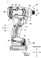
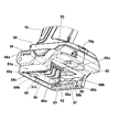
- FIG. 1 is a side view of an impact tool 1 according to an embodiment of the present invention.
- the impact tool 1 is a type of an electric device that includes an electric device main body 10 and a battery pack 100 that can be attached to and detached from the electric device main body 10.
- the impact tool 1 uses a rechargeable battery pack 100 as a power source, drives a rotary hitting mechanism using a motor as a drive source, and converts the rotation of the rotating member into an intermittent hitting force in the rotating direction by the rotary hitting mechanism.
- the tip tool holding section 45 connected to the section is driven.
- the main body housing 11 of the impact tool 1 has three parts, namely, a body part 12 formed in a cylindrical shape for accommodating a motor, a handle part 13 serving as a part to be gripped by one hand by an operator, and a tip of the handle part 13. And a battery pack mounting portion 50 for mounting the detachable battery pack 100.
- the main body housing 11 is manufactured by molding a plastic synthetic resin into two parts on the left and right sides, and is screwed by a plurality of screws 18a to 18h.
- the handle portion 13 extends downward so as to be substantially perpendicular to the center axis (rotation axis A1) of the body portion 12, and controls the turning on or off of the motor at a position where the index finger is located when the operator grips the handle portion.
- An operation lever (trigger lever 16a) of a trigger switch (to be described later with reference to FIG. 3) is provided.
- a forward / reverse switching lever 17 for switching the rotation direction of the motor is provided above and behind the trigger lever 16a.
- a battery pack mounting portion 50 is formed in a lower portion of the handle portion 13 for mounting the battery pack 100.
- the battery pack mounting portion 50 is a portion formed so as to expand in the radial direction from the central axis in the longitudinal direction of the handle portion 13.
- a battery pack 100 that can be attached and detached is attached to the battery pack attachment section 50.
- the battery pack 100 accommodates a plurality of secondary batteries such as lithium ion batteries, and has a rating of 10.8 V in this embodiment from the viewpoint of the type and number of battery cells to be accommodated.
- the battery pack 100 can be used for not only the impact tool 1 but also various electric devices that operate at the same rated voltage.
- the battery pack 100 When the voltage of the battery pack 100 decreases, the battery pack 100 is detached and set in an external charger (not shown) to charge the battery pack 100, so that the battery pack 100 can be used repeatedly.
- the operator pushes the latches 160 (not shown in FIG. 1) and 170, and moves the battery pack 100 in a direction opposite to the mounting direction (forward in FIG. 1). 100 can be removed from the impact tool 1.
- An air inlet 15a formed as a plurality of slits is arranged on the side surface of the body portion 12 and on the rear side. Further, an air outlet 15b is disposed at a position at a predetermined distance from the front side of the air inlet 15a. The position where the air outlet 15b is provided is preferably on the front side of the motor 24.
- An anvil 40 extends in front of the body 12, and a tip tool holding portion 45 for holding a tip tool is provided at a front end of the anvil 40.
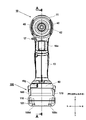
- FIG. 2 is a front view of the impact tool 1 of FIG.
- the outer shapes of the body 12 (see FIG. 1) and the handle 13 are relatively small.
- the body portion 12 has a size necessary to accommodate a motor and a power transmission mechanism to be described later, and the handle portion 13 has an outer diameter optimal for being gripped by an operator.
- the battery pack 100 projects farther in the left-right direction than the handle portion 13, the left-right direction of the battery pack mounting portion 50 is formed larger than the handle portion 13.
- the operation units of the latches 160 and 170 are exposed on the side surface of the battery pack 100.
- the bottom surface 101e (see FIG. 10) of the battery pack 100 is formed flat, so that the impact tool 1 can be placed upright as shown in FIG.
- the housing of the battery pack 100 is formed by a lower case 101 and an upper case 110 made of synthetic resin, and the lower case 101 and the upper case 110 are fixed by screws 108a to 108d (however, 108a and 108b are not visible in FIG. 2). Is done.
- the upper case 110 corresponds to a first case portion
- the lower case 101 corresponds to a second case portion.
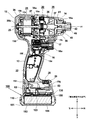
- FIG. 3 is a longitudinal sectional view showing the internal structure of the impact tool 1 of FIG.
- the impact tool 1 is composed of a main body housing 11 (body portion 12, handle portion 13, battery pack mounting portion 50) made of synthetic resin, and a metal hammer case 14 that houses a striking mechanism 35.
- a main body housing 11 body portion 12, handle portion 13, battery pack mounting portion 50
- a metal hammer case 14 that houses a striking mechanism 35.
- the main body housing 11 symbols refer to FIG. 1) is joined.
- the hammer case 14 has a tapered cup shape, has an opening on the rear side, and has a small opening (through hole) through which the anvil 40 passes through the center of the bottom on the front side.
- a protector 14a made of synthetic resin is mounted on a part of the hammer case 14 and behind the tip tool holder 45.
- a motor 24, a reduction mechanism 30 using a planetary gear, and a striking mechanism 35 having a hammer 37 and an anvil 40 are coaxial with the rotation axis A1. It is arranged side by side.
- a trigger switch 16 is provided above the handle portion 13 of the main body housing 11, and a trigger lever 16 a serving as an operation unit is exposed from the trigger switch 16 to the front side of the main body housing 11.
- the trigger switch 16 includes a case having a built-in switch mechanism, and an operation unit (trigger lever 16a) provided outside for driving the switch mechanism. The switch is turned on and off by operating the trigger lever 16a. I do.
- the type and structure of the trigger switch 16 are arbitrary, and not only the slide type trigger lever 16a as in the present embodiment but also a swing type trigger lever that swings around a swing axis may be used. May be used.
- a control circuit board 22 having a function of controlling the speed of the motor 24 by the pulling operation of the trigger lever 16a is accommodated inside the handle portion 13.
- the control circuit board 22 is arranged vertically so as to be parallel to the central axis of the handle portion 13.
- a microcomputer (not shown) (not shown) and a semiconductor switching element (not shown) for forming an inverter circuit are mounted on the control circuit board 22.
- the semiconductor switching element can be configured using six FETs (Field @ effect @ transistor).
- a switch holder 28 in which an operation mode changeover switch and the like are arranged is provided on the outer upper surface of the battery pack mounting portion 50. In front of the switch holder 28, a light emitting unit 29 for irradiating an object to be worked by a tip tool (not shown) is provided.
- a light emitting diode (LED) is used as the light emitting means 29.
- various operation buttons such as a setting button for setting the impact strength, an irradiation switch of the light emitting means 29, a remaining amount check button of the battery pack 100, and corresponding display lamps are arranged.
- the motor 24 is a brushless DC motor, and is driven by an exciting current generated by an inverter circuit.
- the rotating shaft 25 of the motor 24 is arranged so that its axis A1 extends in the longitudinal direction of the body 12.
- the stator of the motor 24 is constituted by a stator core formed by a laminated iron core and formed by a plurality of magnetic pole pieces, and a coil (not shown) wound by using an insulator made of a nonconductor attached to the front and rear sides of the stator core. Is done.
- the rotor (not shown) forms a magnetic path by permanent magnets housed inside the laminated core.
- the motor 24 is supported by a rib 12 a extending from the inside of the body 12 of the main body housing 11 toward the motor 24.
- a cooling fan 26 for cooling the motor 24 is provided axially rearward of the motor 24 and coaxial with the rotating shaft 25.
- the rotating shaft 25 is supported by a bearing 38a on the front side of the stator core and a bearing 38b on the rear side, and the cooling fan 26 is arranged between the bearing 38b and the stator core.
- the cooling fan 26 rotates in synchronization with the motor 24.
- the cooling fan 26 rotates, the outside air is sucked from the air suction port 15a (see FIG. 1) on the rear side of the main body housing 11, the motor 24 is cooled, and after cooling. Is discharged from the air outlet 15b (see FIG. 1) to the outside.
- the sensor board 27 is disposed axially forward of the motor 24 and between the stator core and the bearing 38a.
- the sensor board 27 is provided with three magnetic detecting means (not shown) for detecting a magnetic field of a permanent magnet included in the rotor, and is formed of an annular printed board.
- a commercially available Hall IC can be used as the magnetic detection means, and a plurality of (here, three) Hall ICs are mounted at predetermined intervals at positions facing the permanent magnets of the rotor.
- the motor 24 has a star connection, and an end of a coil (not shown) wound around the stator core is connected to a wiring pattern of the sensor board 27 by soldering.
- the reduction mechanism 30 reduces the output of the motor 24 at a predetermined reduction ratio and transmits the output to the spindle 36.
- a known reduction mechanism using a planetary gear is used.
- the spindle 36 is connected to the output side of the reduction mechanism 30.
- a spindle cam groove (not shown) is formed on the outer peripheral surface, and the planet carrier portion of the reduction mechanism 30 is formed on the rear side of the shaft portion.
- the spindle 36 is manufactured by integral molding of metal from the viewpoint of strength.
- the hammer 37 is arranged on the outer peripheral side of the shaft portion of the spindle 36, and a hammer cam groove is formed on the inner peripheral side.
- the hammer 37 is held by a cam mechanism using a steel ball (not shown), and the outer peripheral surface of the spindle 36 and a part of the inner peripheral surface of the hammer 37 are in contact with each other. In FIG. 3, the cam mechanism is not shown.
- the blade 41 has a shape extending outward in the radial direction, and is hit by a hitting claw of the hammer 37.
- On the side surface in the rotation direction of the blade portion 41 there are formed both a hit surface that is hit when the hammer 37 rotates in the tightening direction and a hit surface that is formed on the opposite side and hit when rotating in the loosening direction.
- the rotating body of the spindle 36 and the anvil 40 is supported on the hammer case 14 by a metal 39 on the front side.
- the tip tool holding portion 45 has a mounting hole 42 having a hexagonal cross section that extends rearward in the axial direction from the front end of the anvil 40 and includes a sleeve that moves back and forth on the outer peripheral side of the anvil 40. .
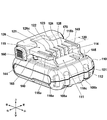
- FIG. 4 is a perspective view of the battery pack 100 according to the embodiment of the present invention.
- the battery pack 100 can be attached to and detached from the battery pack mounting section 50 (see FIG. 1).
- the housing of the battery pack 100 is formed by a lower case 101 and an upper case 110 that can be divided in the vertical direction.
- the lower case 101 and the upper case 110 are made of a member that does not conduct electricity, for example, a synthetic resin, and are fixed to each other by four screws 108a to 108d (108c and 108d are not visible in FIG. 4).
- the upper case 110 has a rail mechanism in which two rail grooves 140 and 145 are formed for attachment to the battery pack mounting portion 50.
- the rail grooves 140 and 145 are grooves having such a shape that the longitudinal direction is parallel to the mounting direction of the battery pack 100 and is depressed inward from the left and right side surfaces 144 and 149 of the upper case 110.
- the front ends of the groove portions of the rail grooves 140 and 145 are open ends, and the rear ends are closed ends connected to the front wall surface of the raised portion 126.
- the rail grooves 140 and 145 are formed in shapes corresponding to the rails 54 and 57 (see FIG. 5 described later) formed in the battery pack mounting portion 50 of the electric device body 10, and the rail grooves 140 and 145 are formed in the rails 54 and 57.
- the battery pack 100 is fixed to the electric device main body 10 by being locked by locking portions 165 and 175 (175 is not visible in FIG.
- the latches 165 and 175 are moved inward by pushing the latches 160 and 170 on the left and right sides inward, and the latched state is released. In this state, the battery pack 100 is moved to the opposite side to the mounting direction.
- a flat lower step surface 111 is formed on the front side of the upper case 110, and an upper step surface 115 that is formed higher than the lower step surface 111 is formed near the center.
- the lower step surface 111 and the upper step surface 115 are formed in a step shape, and a connection portion thereof is a step portion 114 which is a vertical surface.
- a portion on the front side of the upper step surface 115 from the step portion 114 becomes the slot group arrangement region 120.
- a plurality of slots 121 to 125 are formed in the slot group arrangement region 120 so as to extend rearward from the front step 114.
- the slots 121 to 125 are portions cut out so as to have a predetermined length in the battery pack mounting direction.
- the electric device body 10 or an external charging device (not shown) is provided inside the cut out portions.
- a plurality of battery-side terminals 131 to 135 (to be described later with reference to FIG. 7) that can be fitted to the device-side terminals of FIG.
- the slots 121 to 125 are formed so that the terminal on the power tool main body side can be inserted by sliding the terminal from the lower surface 111 side to the rear side.
- the slot 121 on the right side of the rail groove 140 of the battery pack 100 serves as an insertion port for a positive terminal (C + terminal) for charging.
- a slot 122 adjacent to the slot 121 serves as an insertion port for a positive electrode terminal (+ terminal) for discharge.
- the slot 124 on the left side of the battery pack 100 serves as an insertion port for a negative terminal ( ⁇ terminal).
- two signal terminals for signal transmission used to control the battery pack 100, the electric device main body 10, and an external charging device (not shown) are arranged.
- a slot 125 is provided.
- a raised portion 126 On the rear side of the upper step surface 115, a raised portion 126 whose outer shape is raised above the upper step surface 115 is formed. A recessed stopper portion 126c is formed near the center of the raised portion 126.
- the stopper portion 126c is a recess for avoiding the protrusion 69a (see FIG. 5 described later) when the battery pack 100 is mounted on the battery pack mounting portion 50, and the protrusion 69a serves as an abutting surface. I have.
- the projection 69a on the electric device main body 10 side When the projection 69a on the electric device main body 10 side is inserted until it comes into contact with the stopper 126c, a plurality of terminals (device side terminals) provided on the electric device main body 10 and a plurality of terminals provided on the battery pack 100 are provided.
- connection terminals (not shown) are brought into good contact with each other and become conductive.
- the locking portions 165 and 175 (175 are not visible in the drawing) of the latches 160 and 170 protrude in the left and right directions inside the rail grooves 140 and 145 due to the action of a biasing portion such as a spring.
- the battery pack 100 is prevented from falling off by engaging with the notch grooves 56, 59 (56 is not visible in the figure) formed in the rails 54, 57.
- the vicinity of the front end of the bottom surface of each of the rail grooves 140 and 145 is inclined as going from top to bottom.
- hollow portions 115a and 115b for facilitating injection molding are formed in the upper portion of the upper surface 115 above the rail grooves 140 and 145.
- a substantially rectangular parallelepiped hollow portion 112 is formed in a top view.
- the concave portion 112 is an uneven portion used for determining whether or not the battery pack 100 is properly mounted on the electric device main body 10, and is engaged with a protrusion 69 b formed on the electric device main body 10 side.
- mounting is prevented because the positions and shapes of the recess 112 and the protrusion 69b are different. Therefore, even if a plurality of types of battery packs having different voltages are manufactured using substantially the same casing, erroneous connection can be prevented only by changing the positions and shapes of the recess 112 and the protrusion 69b. It becomes possible.
- step portions 118a to 118c are formed on the outer edge of a joint portion serving as a boundary between the electric device main body 10 and the battery pack 100 when viewed from the outside.
- FIG. 5 is a partial perspective view showing the shape of the battery pack mounting portion 50 of the electric device main body 10.
- the battery pack mounting portion 50 corresponding to the shape of the battery pack 100 to be mounted is formed not only in the electric device main body 10 but also in all electric devices powered by the battery pack 100.
- the battery pack mounting portion 50 is formed with rails 54 and 57 projecting inward from inner wall portions on both left and right sides and extending longitudinally in the front-rear direction, and a terminal portion is provided above a space sandwiched therebetween. 60 are provided.
- the rail 57 is formed so as to extend in the front-rear direction and has an upper surface and a lower surface, and the upper surface and the lower surface are engaged with the inner upper wall and the inner lower wall of the rail groove 145 of the battery pack 100 so as to be in contact therewith.
- Hollow portions 58a and 58b are formed between the upper and lower sides of the rail 57. These hollow portions are formed for ease of injection molding of a synthetic resin, and the hollow portions 58a and 58b are functionally formed. You don't have to. In the vicinity of the front end of the rail 57, a notch groove 59 cut out in the vertical direction is formed.
- the notch groove 59 is a portion that becomes a concave portion or a hook portion that engages with a locking claw (locking portion 165) of the latch mechanism.
- the terminal portion 60 is manufactured by integral molding of a non-conductive material such as a synthetic resin, and has a plurality of metal terminals, such as a positive input terminal 62, a negative input terminal 64, an LS terminal 63, and an LD terminal (abnormal signal terminal). ) 65 is cast into the synthetic resin.
- the terminal portion 60 has a vertical surface 60a serving as an abutting surface in the mounting direction (front-rear direction) and a horizontal surface 60b.
- the horizontal surface 60b is adjacent to the upper step surface 115 (described later in FIG. 3) when the battery pack 100 is mounted. , Facing surfaces.
- a curved portion 52 that contacts a raised portion 126 (described later with reference to FIG.
- the protrusion 69a is formed integrally with the housing of the electric device main body 10 formed in two parts in the left-right direction, and serves as a stopper for restricting the mounting direction of the battery pack 100 and the relative movement in the direction perpendicular to the mounting direction.
- a side skirt portion 68a extending in a rib shape toward the lower side of the lower right edge of the lower surface of the rail 54 is formed, and is lower than the left edge of the lower surface of the rail 57.
- a side skirt portion 68b extending in the shape of a rib is formed. Further, the lower end of the rear wall 51c is extended to connect the rear end of the side skirt portion 68a and the rear end of the side skirt portion 68b to form the side skirt portion 68c.
- FIG. 6 is a left side view of the battery pack 100.
- a rail groove 145 is formed on the left side of the battery pack 100.
- the rail groove 145 is a concave portion depressed from the vertical surface to the right on the left side surface 149 of the upper housing 110.
- the rail groove 145 includes a rail groove upper surface 147 (147a to 147d) extending in the front-rear direction and a rail groove lower surface. 146.
- the front end of the rail groove 145 is open, and the rear end is closed by a wall surface continuing from the raised portion 126.
- a latch hole 148 through which a locking portion (latch claw) 175 penetrates is formed on the rear side of the rail groove 145.
- the rail groove lower surface 146 of the rail groove 145 is formed in a flat shape, but the rail groove upper surface 147 is formed so that the height gradually decreases from the front side to the rear side. That is, the front end is formed by a tapered surface 147a so as to spread slightly upward in the upward direction, is formed by a horizontal surface 147b near the middle in the front-rear direction, and becomes a horizontal surface 147d lowered through an oblique step portion 147c behind the front surface.
- the rail 54 on the side of the electric device main body 10 also has a wide vertical width at the entrance open end, and changes to the height of 147a to 147d toward the rear end.
- the battery pack 100 when the battery pack 100 is mounted on the electric device main body 10 until the locking portion 175 contacts the notch groove 56, the battery pack 100 is fixed well.
- the shape of the right side surface of the battery pack 100 and the rail groove 140 (see FIG. 4) have the same shape as the rail groove 145 and are symmetrical with respect to the left and right, so that their illustration is omitted.
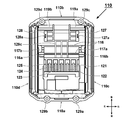
- FIG. 7 is a top view of the battery pack 100.
- An upper case 115 and a lower surface 111 are formed in the upper case 110 of the battery pack 100, and slots 121 to 125 are formed so as to be cut out from the lower surface 111 to the upper surface, and inside the positions of the slots 121 to 125 are formed.
- Battery-side terminals 131 to 135 are arranged.
- a protruding portion 126 protruding upward is formed below the upper step surface 115.
- a stopper 126c is formed near the left and right center of the raised portion 126.
- the raised portion 126 is formed to secure a storage space for the latches 160 and 170 in its internal space.
- Through holes 126a and 126b are formed on both left and right sides of the raised portion 126, and the latches 160 and 170 are formed therefrom.
- the operation unit 170 protrudes.
- the positions of the latches 160 and 170 in FIG. 7 are positions (normal positions) in a non-operated state, and are positions where the respective operation units are projected outward by springs described later.
- the operation direction of the latch 160 is a horizontal direction from right to left, and the latch 170 is in a horizontal direction opposite to the left and right of the latch 160, and each moves linearly on a horizontal plane.
- Hollow portions 115a and 115b are formed above a portion of the upper portion 115 where the rail grooves 140 and 145 are formed. These are formed to facilitate the injection molding of the case 110, and are provided for manufacturing reasons.
- the openings at the front ends of the rail grooves 140 and 145 are formed to be oblique when viewed from above, and configured to guide the mounting of the rails 54 and 57 (see FIG. 5) into the rail grooves 140 and 145.
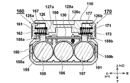
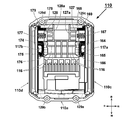
- FIG. 8 is a sectional view taken along line BB of FIG.
- the latches 160 and 170 are held so as to be able to move horizontally in the left-right direction of the battery pack 100, the upper sliding surface is held by the upper case 110, and the lower sliding surface is formed integrally with the separator 150. It is held by a plurality of ribs, namely, ribs 156a, 156b, 157a, and 157b shown in FIG.
- the latch 160 is biased by a spring 167 provided between the inner convex portion 127a and the operation surface 161 to be held in a direction protruding outside from the through hole 126a.
- the latch 170 is urged by a spring 177 provided between the inner convex portion 128a and the operation surface 171 to be held in a direction protruding from the through hole 126b to the outside.
- the springs 167 and 177 are compression coil springs. Below the springs 167, 177, rib-shaped spring stoppers 158a, 158b extending in the left-right direction are formed so as not to fall off when the springs 167, 177 contract.
- the spring stoppers 158a and 158b are formed integrally with the separator 150, and the springs 167 and 177 and the spring stoppers 158a and 158b are in a non-contact state during normal operation.
- Protrusions 163 and 173 for fitting the ends of the springs 167 and 177 are formed on the inside of the operation surfaces 161 and 171 of the latches 160 and 170. As described above, the outer ends of the springs 167 and 177 are held by the protrusions 163 and 173 of the latches 160 and 170, and the inner ends are formed by the protrusions 127a and 128a formed on the spring holding ribs of the upper case. By being held, the springs 167 and 177 are stably held.
- the projections 127a and 128a are formed on extensions of the axes of the through holes 126a and 126b, respectively.
- the convex portions 163 and 173 and the convex portions 127a and 128a are holding members for preventing the springs 167 and 177 from shifting in the radial direction. It may be formed of a cylindrical concave portion that holds the outer peripheral surface of the portion.
- the convex portions 163 and 173 correspond to a first contact portion.
- a lithium ion battery having a rating of 3.6 V is placed in a space defined by combining openings of an upper case 110 having an opening on the lower side and a lower case 101 having an opening on the upper side. Housed inside the book.
- the battery cells 105 to 107 used have a diameter of 18 mm and a length of 65 mm, which is a so-called 18650 size.
- the battery cells 105 to 107 are substantially accommodated in the lower case 101 such that the axial direction is in the front-rear direction, and the battery cells 105 to 107 are stabilized by covering and fixing a separator 150 made of synthetic resin. Fixed.
- the separator 150 also functions as a mounting base for holding the circuit board 130 on the upper part.
- the circuit board 130 serves as a mounting base for soldering the plurality of battery terminals 131 to 135 (see FIG. 7), and mounts battery control circuit components such as a microcomputer.
- a screw hole is formed in the circuit board 130, and the circuit board 130 is fixed by a screw 180 screwed with a screw boss 155 formed on the separator 150.
- the separator 150 is manufactured by integral molding of a synthetic resin such as plastic, which is a non-conductive material, and is shaped to cover the upper half surface of the outer peripheral surface of the battery cells 105 to 107. Joint surfaces 150a and 150b are formed so as to be in contact with the inner wall surface.
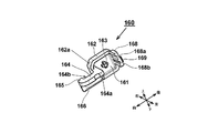
- FIG. 9 is a perspective view of the latch 160 alone, viewed from the inside.
- the latch 160 mainly includes an operation portion (the operation surface 161 and the outer frame portion 162) operated by an operator and an arm portion 164 extending forward from the operation portion.
- the parts shown can be manufactured by integral molding of a synthetic resin.
- the arm 164 is formed of a plate-like horizontal wall that is curved in a bow shape when viewed from above, and a rib 156a (see FIG. 10 described later) formed on the separator 150 near the rear end of the lower surface 164a of the arm 164. Reference).
- the front end on the front side of the latch serves as a locking portion 165 serving as a latch claw, and the rear end of the arm 164 is connected to the outer frame 162.
- the arm 164 has a vertical wall 166 that extends downward along the right side contour.
- the arc-shaped right side wall surface 164b of the vertical wall portion 166 is formed to have the same shape as a stopper portion 117a (see FIG. 12 described later) formed on the upper case 110, and the stopper portion 117a and the vertical wall portion 166 are in contact with each other. This limits the amount of movement of the arm portion 164 in the outward direction (rightward direction).
- a plurality of fine grooves are formed in the outer wall of the operation surface 161 in the horizontal direction, and a protrusion 163 for holding the spring 167 (see FIG. 8) is formed in the center of the inner wall.
- a rear wall portion 168 extending leftward is formed on the rear side of the outer frame portion 162.
- the rear wall portion 168 slides on the rear surface thereof with the inner wall portion of the upper case 110, so that the movement of the latch 160 in the horizontal plane is smoothly held.
- a stopper piece 169 extending horizontally from a part of the rear wall portion 168 to the rear side is formed.
- the right side of the stopper piece 169 contacts the inner wall surface of the upper case 110, thereby limiting the amount of movement of the latch 160 in the outward direction (rightward direction).
- Two grooves 168a and 168b extending in the horizontal direction are formed on the surface of the rear wall 168 on the side of the spring 167 (see FIG. 8). These two grooves 168a and 169b are provided to reduce the thickness of the latch 160.
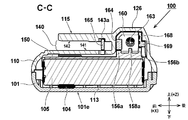
- FIG. 10 is a sectional view taken along line CC of FIG.
- a rail groove 140 extending in the front-rear direction is formed on the right side surface of the upper case 110. At the cross-sectional position along the line CC, the rail groove 140 appears to be vertically separated. The distance between the upper surface 142 and the lower surface 141 of the rail groove 140 is substantially constant.
- the lower surface of the arm portion 164 of the latch 160 connected to the outer frame portion 162 abuts on a rib 156 a formed integrally with the separator 150, thereby defining the lower position.
- the lower surface of the rear wall portion 168 formed on the rear side of the outer frame portion 162 of the latch 160 abuts on a rib 156 b formed integrally with the separator 150, thereby defining the lower position.
- a spring stopper 158a is further formed between the ribs 156a and 156b.
- the spring stopper 158a is located below the spring 167 (see FIG. 8), and is normally in non-contact with the spring 167, but acts to suppress the deformation when the spring 167 is distorted downward and deformed.
- the spring stopper 158a also functions as a stopper for a slide position when the lower portion of the outer frame portion 162 of the latch 160 is pushed into the inside (left side) of the upper case 110.
- a stopper 169 is formed on the lower part of the right end of the rear wall 168 of the latch 160 so as to extend rearward from the vertical plane of the rear wall 168.
- the rightward movement when the latch 160 is released is limited by contacting the right inner wall. Therefore, the movement position when the latch 160 is pushed in is regulated by the spring stopper 158a, and the rightward movement when the latch 160 is released is regulated by the stopper piece 169 and the right wall surface 164b (see FIG. 9). That is, both the support of the latch and the restriction of the movement of the latch can be realized by the support member.
- the locking portion 165 of the latch 160 protrudes rightward from a latch hole 143 (see FIG. 6, the left latch hole 148 is visible in FIG. 6) formed near the rear end of the rail groove 140.
- the latch hole 143 is also formed in a concave shape on the rail groove upper surface 142 of the rail groove 140, and the upper end portion of the locking portion 165 is located inside the concave portion 143a.
- the rear side of the outer frame portion 162 is guided to the upper case 110 by the rear wall portion 168, and the front side of the outer frame portion 162 is guided to the upper case 110 by the left and right extending portions of the arm portion 164. Therefore, when the latch 160 moves in the left-right direction (movement in the ⁇ Y direction), movement in the rotation direction about the Z axis is prevented. Therefore, the latch 160 can smoothly slide (slide) in the Y direction (left-right direction).
- the battery cell 105 is directly held by the lower case 101 in a portion below the separator 150 located below the latch 160.
- a plurality of ribs 113 whose upper shapes are formed in a curved shape for fixing the battery cells 105a are formed at equal intervals.
- a cushion member 104 is interposed below the battery cells 105 to 107 to absorb the shock transmitted from the lower case 101 to the battery cells 105 to 107.
- the separator 150 of the present embodiment has a shape that covers only the upper half surface of the battery cells 105 to 107, instead of a shape that is widely used in the past, which covers all the upper and lower sides of the battery cells 105 to 107.
- the height of the battery pack 100 in the vertical direction could be reduced by the amount of the separator interposed between the battery cells 105 to 107 and the bottom surface 101e of the lower case 101.
- a cover member for holding the latch 160 interposed between the latch 160 and the separator 150, which is required in the conventional battery pack, is unnecessary in the latch 160, so that The height of the battery pack 100 in the vertical direction could be reduced by the amount of the omitted members.
- the distance between the rail groove lower surface 141 of the rail groove 140 and the bottom surface 101 e of the lower case 101 is close to the diameter of the battery cell 105 to be housed. It can be understood that the battery pack 100 of the present embodiment is formed compact.
- FIG. 11 is a bottom view of the upper case 110 and shows a state before the latches 160 and 170 are attached.
- the upper case 110 has a front wall 110a, a rear wall 110b, a right side wall 110c and a left side wall 110d, and is substantially rectangular when viewed from the bottom.
- the front wall 110a and the rear wall 110b are used for screwing the lower case 101 to the lower case 101.
- a plurality of screw bosses 129a to 129d are formed.
- a slot group arrangement region 120 (see FIG. 4) is formed on the front side of the inner wall portion of the upper case 110 from the center in the front-rear direction, so that slots 121 to 125 are formed side by side in the left-right direction.
- a rib 128c having a large amount of protrusion from the front surface of the inner wall of the upper case 110
- a protrusion amount Is provided on the inner wall portion (upper wall portion) on the rear side of the upper case 110.
- hatching is applied to a portion of the rib 116 having a small protrusion amount that comes into contact with the upper portions (upper surfaces) of the latches 160 and 170.
- the horizontal movement of the horizontal rib 169 (see FIG. 9) of the latch 160 is guided by the step portion 119a.
- a rib 128c intersecting with the two ribs 116 extending in the left and right direction is provided.
- portions indicated by hatching lines define the upper positions of the arm portions 164 and 174 by contacting the arm portions 164 and 174 of the latches 160 and 170.
- the rib 116 is formed to be elongated in the left-right direction and to have a reduced width (length in the front-rear direction).
- Column-shaped stoppers 117a and 117b extending in the vertical direction are formed adjacent to the right and left ends of the rib 116.
- the stoppers 117a and 117b are portions where the outer arc surfaces (right side wall surface 164b) of the arm portions 164 and 174 come into contact when the latches 160 and 170 are not operated.
- the ribs 116 around the arms 164 and 174 are connected to the connecting surfaces 116a and 116b formed in a planar shape to prevent rattling of the arms 164 and 174 in the vertical direction.
- steps 119a and 119b with which the rear walls 168 and 178 of the latches 160 and 170 abut.
- the protrusions of the steps 119 a and 119 b from the front of the inner wall of the upper case 110 are formed to be equal to the ribs 116. Therefore, in FIG. 11, the hatched portion mainly serves as the sliding surface that holds the upper portions of the latches 160 and 170.
- Spring holding ribs 127 and 128 are formed on the left and right sides in front of the step portions 119a and 119b.
- the spring holding ribs 127 and 128 are portions for holding the ends of the springs 167 and 177 (see FIG.
- FIG. 12 is a bottom view of the upper case 110, showing a state after the latches 160 and 170 are attached from the state of FIG.
- the latches 160 and 170 are biased outward in the left-right direction by two springs 167 and 177.
- the latches 160 and 170 are blackened and hatched (164 and 174) so that the reference positions of the latches 160 and 170 (positions not operated by the operator) can be recognized.
- the horizontal ribs 169, 179 extending from the rear wall portions 168, 178 of the latches 160, 170 are held by step portions 119a, 119b (see FIG. 11) formed on the wall surface of the upper case 110.
- the upper surfaces of the arm portions 164 and 174 of the latches 160 and 170 are held by the rib 116.
- the vertical wall portions 166 and 176 extending downward from the arm portions 164 and 174 are painted black, and the other portions are hatched.
- column-shaped stopper portions 117a and 117b extending in the vertical direction are formed on the outer curved portions of the arm portions 164 and 174 in the upper case 110, the latch 160 cannot move outward from the position shown in the right direction. Similarly, the latch 170 cannot move leftward outward from the position shown. As shown in FIG.
- the attachment of the latches 160 and 170 to the inside of the upper case 110 does not require a tool such as a screwdriver, and the other ends of the springs 167 and 177 are engaged with the latches 160 and 170. It only needs to be fitted into predetermined positions (convex portions 127a, 128a) of the upper case 110. Thereafter, the upper case 110 is turned upside down, and the lower case 101 and the upper case 110 are aligned and then screwed.
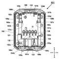
- FIG. 13 is a top view showing the lower case 101 of the battery pack 100 and the objects accommodated therein. In other words, it is also a top view in a state where the upper case 110 is removed from the battery pack 100.
- three battery cells 105 to 107 are accommodated, and a separator 150 made of synthetic resin is provided thereon.
- Four screw holes 109a to 109d are formed near the front wall 101a and the rear wall 101b of the lower case 101, and the upper case 110 is fixed using four screw screws 108a to 108d (see FIG. 6 and the like). .
- a circuit board 130 is provided above the separator 150.
- the front side of the circuit board 130 is hooked by the hook 154a, and the rear side is fixed by screws 180.
- Notch portions 131a and 131b are formed on both left and right sides of the circuit board 130, and are engaged with the ribs 156a and 157a formed integrally with the separator 150 to increase the efficiency of the work of attaching the circuit board 130 to the separator 150.
- five battery terminals 131 to 135 are provided in the forward portion of the circuit board 130.
- the battery-side terminals 131 to 135 were formed by cutting a flat plate made of a conductive metal by press working and then bending it into a U-shape.
- Ribs 156a, 156b, 157a, 157b, 158a, 158b serving as support members provided on the separator 150 are arranged on both sides in the left-right direction of the circuit board 130.
- the circuit board 130 can be easily positioned on the separator 150 by these support members, and can be fixed to the separator 150 with the screws 180 after positioning, so that the assemblability can be improved.
- a plurality of ribs are formed on the upper surface of the separator 150 in accordance with the mating member to be brought into contact.
- the ribs 154b and 154c extending in the longitudinal direction (front-back direction) are formed to hold the circuit board 130.
- ribs 152a to 152c which are formed in a convex shape so as to come into contact with the inner wall of the upper case 110 when the upper case 110 is screwed are formed.
- ribs 153a to 153d are formed in the vicinity of the left end of the separator 150 so as to abut on the inner wall of the upper case 110 when the upper case 110 is screwed.
- Two ribs 156a, 156b, 157a and 157b for holding the latches 160 and 170 are formed in the inner regions of the ribs 152c and 153d. These ribs 156a, 156b, 157a, and 157b are formed on the upper surface of the separator 150, and are formed such that long sides are oriented in the left-right direction.
- a spring stopper 158a for preventing the spring 167 (see FIG. 8) from coming off is formed between the ribs 156a and 156b.
- a spring stopper 158b for preventing the spring 177 (see FIG. 8) from coming off is formed between the ribs 157a and 157b.
- the ribs 156a, 156b, 157a, and 157b formed on the separator 150 are sandwiched between the upper case 110 without providing a dedicated pressing member for fixing the latches 160 and 170 to the upper case 110.
- the latches 160 and 170 are held, so that the number of components can be reduced and the height of the battery pack 100 in the vertical direction can be reduced.
- the exclusive holding member is omitted, the latches 160 and 170 can be temporarily fixed to the upper case 110 during assembly, so that stable assembly can be performed while maintaining a state where the assemblability is not impaired. It becomes possible.
- the size of the battery pack can be reduced by reducing the number of parts, and the efficiency of assembly and the cost can be reduced.
- the present invention has been described based on the embodiments.
- the present invention is not limited to the above-described embodiments, and various modifications can be made without departing from the gist of the present invention.
- an example was described in which the present invention was applied to a battery pack in which the longitudinal direction of the battery cell was parallel to the mounting direction of the battery pack.
- the present invention may be applied to a battery pack whose direction is orthogonal to the mounting direction of the battery pack.
- the present invention is not limited to a battery pack in which battery cells are arranged in a horizontal direction, and the present invention can be similarly applied to a battery pack in which battery cells are stacked in two layers in a horizontal direction and an upper and lower direction.
- the latches 160 and 170 are supported by the ribs 156a, 156b, 157a, and 157b of the separator 150, the ribs are configured to protrude upward from portions other than the re-separator 150, such as the circuit board 130 and the lower case 101. May be provided, and the latch may be supported by the rib.
- negative electrode input terminals 68a to 68c ... side skirt portions , 69a, 69b: Projection
- 100 Battery pack
- 101 Lower case
- 101a Front wall
- 101b Rear wall
- 101c Right side wall
- 101d Left side wall
- 101e Bottom surface
- 104 Cushion material, 105 to 107 ... battery cells, 108a to 108d ... screws, 109a to 109d ... screw holes, 110 ... upper case, 111 ... lower surface, 112 ... recessed parts, 113 ...
- 114 stepped portion, 115: upper surface, 115a, 115b: hollow portion, 116: rib, 116a, 116b: connecting surface, 117a, 117b: stopper portion, 118a to 118c: stepped portion, 119a, 119b: stepped portion, 120: slot group arrangement area, 121 to 125: slot, 126: raised part, 126a, 126b: through hole, 127, 128: spring holding rib (second contact part), 127a, 128a: convex part, 129a to 129d ... Screw boss, 130 ... Circuit board, 131-135 ... Battery side terminal, 140,145 ... Rail groove, 141,146 ... Rail groove lower surface, 142,147 ...
- Protrusion (first contact part), 164,174 ... Arm part, 164a Bottom surface, 164b Right wall surface, 165, 175 Locking portion, 166, 176 Vertical wall portion, 167, 177 Spring, 168, 178 Rear wall portion, 169, 179 Horizontal rib, A1 rotation axis
Abstract
Provided is a battery pack which is miniaturized by reducing the number of components of a latch mechanism of the battery pack. In the battery pack comprising housings (101, 110) that accommodate a plurality of battery cells 106, and detachable latches 160, 170, the latches have manipulation parts 161, 171 that are manipulated by an operator, springs 167, 177 that bias the manipulation parts to the outside of the housings, and first abutting parts 163, 173 on which ends of the springs abut. The manipulation parts move horizontally below the upper wall of the housing (110), and portions thereof are exposed to the outside from through-holes 126a, 126b formed in the housing. Furthermore, the latches are supported from below by any one among a separator 150 holding the battery cell, a circuit board 130, and a lower case 101.
Description
本発明は、ケース内に複数の電池セルを収容し、着脱可能な電池パック及びそれを用いた電気機器に関する。
The present invention relates to a detachable battery pack in which a plurality of battery cells are accommodated in a case and an electric device using the same.
電力でモータを回転させ、その回転運動を動作部材の往復運動または回転運動の少なくとも一方に変換するようにした電動工具や、電気エネルギーによって光を発する照明機器や、音を発する音響機器等の電気機器において、電源として電池パックを用いることが広く用いられている。電池パックは、充放電可能な電池セルを複数本含み、これらを合成樹脂製のケース内に収容する。電池パックには、電池側レール部を用いた電気機器本体への着脱機構と、装着時に電気的な接続を可能とするターミナル部が設けられる。一方、電気機器本体側には電池側レール部を案内する機器側レール部が設けられる。このような電池パックが取り付けられ、又は、取り外される電気機器は、インパクトドライバ、ドライバドリル、グラインダ、サンダ、釘打ち機、ネジ打ち機、タッカ、集塵機、送風機、ポンプ、高圧洗浄機、チェンソー、草刈機、剪定器具、耕耘機、トーチライト、ラジオ等、様々な機器にまで及んでいる。電池パックは、所定の電気容量を有することが求められる一方で、小型で軽量であることが要求される。このような電池パックを用いた電気機器(電動工具)の一例として特許文献1が知られている。
Electric power such as a power tool that rotates a motor with electric power and converts the rotating motion into at least one of a reciprocating motion and a rotating motion of an operating member, a lighting device that emits light by electric energy, and an acoustic device that emits sound. It is widely used to use a battery pack as a power source in equipment. The battery pack includes a plurality of chargeable / dischargeable battery cells, and these are accommodated in a synthetic resin case. The battery pack is provided with an attachment / detachment mechanism to / from the electric device main body using the battery-side rail portion, and a terminal portion that enables electrical connection at the time of attachment. On the other hand, a device-side rail portion for guiding the battery-side rail portion is provided on the electric device main body side. The electric equipment to which such a battery pack is attached or detached includes an impact driver, a driver drill, a grinder, a sander, a nailer, a screw driver, a tacker, a dust collector, a blower, a pump, a high-pressure washer, a chain saw, and a mowing machine. It extends to a variety of equipment, such as machines, pruning equipment, tillers, torch lights, radios, etc. While the battery pack is required to have a predetermined electric capacity, it is required to be small and lightweight. Patent Document 1 is known as an example of an electric device (power tool) using such a battery pack.
電池パックには、電気機器本体に対して水平にスライドさせて装着及び取り外しを可能とするための着脱機構と、装着時に着脱機構から外れないようにロックするラッチ機構が設けられる。特許文献1のラッチ機構は、電池パックの右側及び左側側面から外側に突出するラッチボタン(操作部)を有し、電池パックの取外し時には、ラッチボタンを内側に押し込んでラッチ爪を一時的に引っ込めるようにして、ラッチ爪と電気機器本体側のラッチ穴との係合状態を解除する。電池パックを電気機器本体に装着すると、電池パックのラッチ機構が、バネの作用によってラッチ爪を電気機器本体側のラッチ穴と係合させた状態にて保持することで、電池パックが電気機器本体に保持される。また、ラッチ爪が電気機器本体側のラッチ穴と係合させた状態まで装着されると、電池パックの複数の電池側端子と、電気機器本体側の複数の機器側端子が互いに接触し、電力供給が可能となる。
The battery pack is provided with an attachment / detachment mechanism for allowing the attachment / detachment to be slid horizontally with respect to the electric device main body, and a latch mechanism for locking the attachment / detachment mechanism so as not to come off from the attachment / detachment mechanism. The latch mechanism of Patent Literature 1 has a latch button (operation unit) that protrudes outward from the right and left side surfaces of the battery pack, and when removing the battery pack, pushes the latch button inward to temporarily retract the latch claw. Thus, the engagement state between the latch claw and the latch hole on the electric device main body side is released. When the battery pack is attached to the main body of the electric device, the latch mechanism of the battery pack holds the latch claw in a state of being engaged with the latch hole on the side of the main body of the electric device by the action of a spring. Is held. Also, when the latch claw is mounted until it is engaged with the latch hole of the electric device main body, the plurality of battery terminals of the battery pack and the plurality of device terminals of the electric device main body come into contact with each other, and the power Supply becomes possible.
電池パックのハウジングは、上ケースと下ケースに分割して構成され、ラッチ機構は電池パックの上ケース側に、左右方向に水平に移動(摺動)可能なように支持されている。上ケースの内側上壁には、ラッチ機構の移動(摺動)を案内する摺動部が形成され、摺動部に接触状態にて取りつけられるラッチ部を、下方から押さえるカバー部材を上ケース内側に固定することによってラッチ部を保持する。このカバー部材は、上ケースとは別部材であって、カバー部材は上ケースにネジ止めされる。特許文献1のラッチ機構では、右側側面のラッチ機構用と左側側面のラッチ機構用に、それぞれカバー部材を設けるために、部品点数が多くなる上に、ネジ止め作業のための組み立て作業の工数が多かった。また、ラッチ機構を保持するためのカバー部材の設置スペースが必要とされるので、電池パックの小型化実現を阻害していた。
The housing of the battery pack is divided into an upper case and a lower case, and the latch mechanism is supported on the upper case side of the battery pack so as to be horizontally movable (slidable) in the left-right direction. A sliding portion that guides the movement (sliding) of the latch mechanism is formed on the inner upper wall of the upper case, and a cover member that presses the latch portion mounted in contact with the sliding portion from below is provided on the inner side of the upper case. To hold the latch section. This cover member is separate from the upper case, and the cover member is screwed to the upper case. In the latch mechanism of Patent Literature 1, the cover members are provided for the right side latch mechanism and the left side latch mechanism, respectively, so that the number of parts increases and the man-hour for assembly work for screwing work increases. There were many. Further, a space for installing a cover member for holding the latch mechanism is required, which hinders the miniaturization of the battery pack.
本発明は上記背景に鑑みてなされたもので、その目的は、部品点数を抑えた電池パック及び電気機器を提供することにある。
本発明の他の目的は、ラッチ機構の可動部を、電池パック内のインシュレータにて保持するようにして、電池パックの高さ方向の大きさを小さくした電池パック及び電気機器を提供することにある。
本発明の他の目的は、ラッチ機構の可動部と摺動面との保持構造を改良して、ラッチ機構がスムーズに動作できるようにした電池パック及び電気機器を提供することにある。 The present invention has been made in view of the above background, and an object of the present invention is to provide a battery pack and an electric device with a reduced number of components.
Another object of the present invention is to provide a battery pack and an electric device in which a movable portion of a latch mechanism is held by an insulator in the battery pack to reduce the size of the battery pack in the height direction. is there.
It is another object of the present invention to provide a battery pack and an electric device in which a structure for holding a movable portion and a sliding surface of a latch mechanism is improved so that the latch mechanism can operate smoothly.
本願において開示される発明のうち代表的な特徴を説明すれば次のとおりである。
本発明の一つの特徴によれば、複数の電池セルと、第1ケース部と第1ケース部の下方に位置する第2ケース部を有し、複数の電池セルを収容するハウジングと、ハウジングに設けられるラッチ部を備え、ラッチ部は作業者に操作される操作部と、操作部をハウジングの外側に付勢する付勢部と、付勢部の一端側が当接する第1当接部を有する。操作部は、ハウジングの上壁の内側において水平方向に移動するものであって、その一部がハウジングに形成された貫通穴から外部に露出する。ラッチ部の水平方向の移動を規制する支持部を第2ケース部側に設けた。支持部はラッチ部を下方から支持する。電池を保持する部材に支持部を設けた。電池セルを保持する部材としてセパレータを設けて、セパレータにラッチ部を下方から支持すると共にラッチ部の水平方向の移動を規制する支持部を形成した。セパレータは電池セルを整列状態に維持する合成樹脂の成形品であり、ラッチ部の支持部は、セパレータの表面から突出するように形成されたリブ状の凸部であって、凸部の上面が操作部の下面との摺動面となるように構成した。凸部は、セパレータの上面に形成された左右方向に長辺を有する複数のリブにて形成すると良い。 The typical features of the invention disclosed in the present application will be described as follows.
According to one feature of the present invention, a housing having a plurality of battery cells, a first case portion and a second case portion located below the first case portion, and housing the plurality of battery cells, A latch portion is provided, and the latch portion has an operating portion operated by a worker, an urging portion for urging the operating portion to the outside of the housing, and a first contact portion with which one end of the urging portion abuts. . The operation unit moves in the horizontal direction inside the upper wall of the housing, and a part of the operation unit is exposed to the outside through a through hole formed in the housing. A support portion for restricting horizontal movement of the latch portion is provided on the second case portion side. The support portion supports the latch portion from below. A supporting portion was provided on a member for holding the battery. A separator was provided as a member for holding the battery cell, and a support portion for supporting the latch portion from below on the separator and restricting the horizontal movement of the latch portion was formed. The separator is a molded product of a synthetic resin that maintains the battery cells in an aligned state. It is configured to be a sliding surface with the lower surface of the operation unit. The protrusions may be formed by a plurality of ribs formed on the upper surface of the separator and having long sides in the left-right direction.
本発明の他の特徴によれば、ハウジングは、電気機器本体に装着するためのレール部及び接続端子が形成された上側ケースと、上側ケースによって閉鎖されることによって内部に電池セルを複数収容する空間を形成する下側ケースと、を有し、上側ケースの側壁面に貫通穴が形成され、貫通穴の軸線の延長上に付勢部の他端側が当接する第2当接部を設け、第2当接部は付勢部の他端の少なくとも一部を囲む囲い部を有するように構成した。
According to another feature of the present invention, the housing accommodates a plurality of battery cells therein by being closed by the upper case in which a rail portion and a connection terminal are formed for mounting on the main body of the electric device. A lower case forming a space, a through hole is formed in the side wall surface of the upper case, and a second contact portion is provided on the extension of the axis of the through hole, the other end of the biasing portion abutting, The second contact portion is configured to have an enclosing portion surrounding at least a part of the other end of the urging portion.
本発明のさらに他の特徴によれば、付勢部はコイルバネであって、第1当接部及び第2当接部にそれぞれ、コイルバネの中心に突出することによりコイルバネを保持する凸部か、又は、コイルバネの端部を部分的に収容することによりコイルバネを保持する凹部を形成した。また、電池パックには複数の電池セルを整列状態に維持するセパレータと、セパレータの上方に固定される回路基板を有し、支持部は回路基板に設けられる。また、支持部は第2ケース部(下側ケース)に設けられても良い。以上の構成の電池パックを、電池パック装着部を有す電気機器本体に取り付けることにより電気機器が構成される。
According to still another feature of the present invention, the urging portion is a coil spring, and each of the first contact portion and the second contact portion is a projection that holds the coil spring by projecting to the center of the coil spring, Alternatively, a concave portion for holding the coil spring is formed by partially receiving the end of the coil spring. Further, the battery pack has a separator for maintaining a plurality of battery cells in an aligned state, and a circuit board fixed above the separator, and the support portion is provided on the circuit board. Further, the support portion may be provided on the second case portion (lower case). An electric device is configured by attaching the battery pack having the above configuration to an electric device body having a battery pack mounting portion.
本発明によれば、上ケースの内側のラッチを固定するために取りつけられる別部材(ケース部材)を省略したので、電池パックの部品点数の削減を図ることができる。また、セパレータに形成されたリブによって同等の機能を果たすようにしたので、電池パックの部品点数の削減を図ることができ、電池パックの小型化も達成できる。また、支持部材によってラッチを支持するだけでなくラッチの移動を規制する機能も兼用することができる。また、支持部材によって回路基板の位置決めを行うことができる。また、上ケースだけで、コイルバネを含むラッチ部を仮固定できるように構成したので、組み立て作業効率が大いに向上する。
According to the present invention, since a separate member (case member) attached to fix the latch inside the upper case is omitted, the number of parts of the battery pack can be reduced. Further, since the same function is performed by the ribs formed on the separator, the number of parts of the battery pack can be reduced, and the size of the battery pack can be reduced. In addition, the function of not only supporting the latch with the support member but also restricting the movement of the latch can also be used. Further, the circuit board can be positioned by the support member. Further, since the latch portion including the coil spring can be temporarily fixed only by the upper case, the assembling work efficiency is greatly improved.
以下、本発明の実施例を図面に基づいて説明する。本実施例では、電気機器の一例としてインパクト工具1を用いて説明する。尚、本明細書において、インパクト工具1の上下方向は図中に示す方向であるとして説明するが、電池パック単体の方向は、電池パック100の装着方向を基準にして図2~図7に示すように装着方向からみて前側、後側と定義して説明する。
Hereinafter, embodiments of the present invention will be described with reference to the drawings. In the present embodiment, an explanation will be given using an impact tool 1 as an example of an electric device. In this specification, the vertical direction of the impact tool 1 will be described as the direction shown in the drawings, but the direction of the battery pack alone is shown in FIGS. 2 to 7 with reference to the mounting direction of the battery pack 100. As described above, the front side and the rear side when viewed from the mounting direction will be described.
図1は本発明の実施例に係るインパクト工具1の側面図である。インパクト工具1は、電気機器本体10と、電気機器本体10に装着及び取り外し可能な電池パック100によって構成される電気機器の一種である。インパクト工具1は、充電可能な電池パック100を電源とし、モータを駆動源として回転打撃機構を駆動し、回転打撃機構によって回転部材の回転を回転方向の間欠的な打撃力に変換し、打撃機構部に連結された先端工具保持部45を駆動する。インパクト工具1の本体ハウジング11は3つの部分、即ちモータを収容するための筒状に形成される胴体部12と、作業者が片手で把持する部分となるハンドル部13と、ハンドル部13の先端に設けられ、着脱可能な電池パック100を取りつけるための電池パック装着部50から構成される。本体ハウジング11は、プラスチックの合成樹脂の成形によって、左右に2分割形式にて製造され、複数のネジ18a~18hによってネジ止めされる。ハンドル部13は胴体部12の中心軸線(回転軸線A1)と略直交するように下方に延在し、作業者が把持した際に人差し指が位置する箇所には、モータのオン又はオフを制御するためのトリガスイッチ(図3にて後述)の操作レバー(トリガレバー16a)が設けられる。トリガレバー16aの後上方には、モータの回転方向を切り換える正逆切替レバー17が設けられる。
FIG. 1 is a side view of an impact tool 1 according to an embodiment of the present invention. The impact tool 1 is a type of an electric device that includes an electric device main body 10 and a battery pack 100 that can be attached to and detached from the electric device main body 10. The impact tool 1 uses a rechargeable battery pack 100 as a power source, drives a rotary hitting mechanism using a motor as a drive source, and converts the rotation of the rotating member into an intermittent hitting force in the rotating direction by the rotary hitting mechanism. The tip tool holding section 45 connected to the section is driven. The main body housing 11 of the impact tool 1 has three parts, namely, a body part 12 formed in a cylindrical shape for accommodating a motor, a handle part 13 serving as a part to be gripped by one hand by an operator, and a tip of the handle part 13. And a battery pack mounting portion 50 for mounting the detachable battery pack 100. The main body housing 11 is manufactured by molding a plastic synthetic resin into two parts on the left and right sides, and is screwed by a plurality of screws 18a to 18h. The handle portion 13 extends downward so as to be substantially perpendicular to the center axis (rotation axis A1) of the body portion 12, and controls the turning on or off of the motor at a position where the index finger is located when the operator grips the handle portion. An operation lever (trigger lever 16a) of a trigger switch (to be described later with reference to FIG. 3) is provided. A forward / reverse switching lever 17 for switching the rotation direction of the motor is provided above and behind the trigger lever 16a.
ハンドル部13内の下部は、電池パック100を取り付けるために電池パック装着部50が形成される。電池パック装着部50はハンドル部13の長手方向中心軸から径方向に広がるように形成された部分である。電池パック装着部50には、装着及び取り外しが可能な電池パック100が装着される。電池パック100はリチウムイオン電池等の二次電池を複数本収容したもので、収容する電池セルの種類と本数の観点から本実施例では定格10.8Vである。電池パック100は、インパクト工具1だけでなく同じ定格電圧で動作する様々な電気機器にて利用可能である。電池パック100の電圧が低下した場合には、電池パック100を取り外して図示しない外部充電器にセットすることにより充電を行うことで繰り返しの使用が可能である。電池パック100を取り外す際には、作業者がラッチ160(図1では見えない)、170を押し込みながら、電池パック100を装着方向と反対方向(図1で前方)に移動させることで、電池パック100をインパクト工具1から取り外すことができる。
A battery pack mounting portion 50 is formed in a lower portion of the handle portion 13 for mounting the battery pack 100. The battery pack mounting portion 50 is a portion formed so as to expand in the radial direction from the central axis in the longitudinal direction of the handle portion 13. A battery pack 100 that can be attached and detached is attached to the battery pack attachment section 50. The battery pack 100 accommodates a plurality of secondary batteries such as lithium ion batteries, and has a rating of 10.8 V in this embodiment from the viewpoint of the type and number of battery cells to be accommodated. The battery pack 100 can be used for not only the impact tool 1 but also various electric devices that operate at the same rated voltage. When the voltage of the battery pack 100 decreases, the battery pack 100 is detached and set in an external charger (not shown) to charge the battery pack 100, so that the battery pack 100 can be used repeatedly. When removing the battery pack 100, the operator pushes the latches 160 (not shown in FIG. 1) and 170, and moves the battery pack 100 in a direction opposite to the mounting direction (forward in FIG. 1). 100 can be removed from the impact tool 1.
胴体部12の側面であって、後方側には複数のスリットとして形成された空気吸入口15aが配置される。また、空気吸入口15aよりも前方側に所定の距離を隔てた位置には、空気排出口15bが配置される。空気排出口15bの設けられる位置は、モータ24よりも前方側であると良い。胴体部12の前方側にはアンビル40が延出し、アンビル40の前端部には先端工具を保持するための先端工具保持部45が設けられる。
An air inlet 15a formed as a plurality of slits is arranged on the side surface of the body portion 12 and on the rear side. Further, an air outlet 15b is disposed at a position at a predetermined distance from the front side of the air inlet 15a. The position where the air outlet 15b is provided is preferably on the front side of the motor 24. An anvil 40 extends in front of the body 12, and a tip tool holding portion 45 for holding a tip tool is provided at a front end of the anvil 40.
図2は図1のインパクト工具1の正面図である。胴体部12(図1参照)とハンドル部13の外形は比較的小さく形成される。胴体部12は後述するモータや動力伝達機構を収容するのに必要なサイズとされ、ハンドル部13は作業者にて把持されるのに最適な外径とされる。一方、電池パック100はハンドル部13よりも左右方向に大きく突出するため、電池パック装着部50の左右方向はハンドル部13よりも大きく形成される。電池パック100の側面には、ラッチ160、170の操作部が露出する。電池パック100の底面101e(図10参照)はフラットに形成され、インパクト工具1を図2のように正立させて載置することを可能とする。電池パック100は合成樹脂製の下ケース101と上ケース110によりその筐体が形成され、下ケース101と上ケース110はネジ108a~108d(但し、108a、108bは図2では見えない)によって固定される。上ケース110は第1ケース部に相当し、下ケース101は第2ケース部に相当する。
FIG. 2 is a front view of the impact tool 1 of FIG. The outer shapes of the body 12 (see FIG. 1) and the handle 13 are relatively small. The body portion 12 has a size necessary to accommodate a motor and a power transmission mechanism to be described later, and the handle portion 13 has an outer diameter optimal for being gripped by an operator. On the other hand, since the battery pack 100 projects farther in the left-right direction than the handle portion 13, the left-right direction of the battery pack mounting portion 50 is formed larger than the handle portion 13. The operation units of the latches 160 and 170 are exposed on the side surface of the battery pack 100. The bottom surface 101e (see FIG. 10) of the battery pack 100 is formed flat, so that the impact tool 1 can be placed upright as shown in FIG. The housing of the battery pack 100 is formed by a lower case 101 and an upper case 110 made of synthetic resin, and the lower case 101 and the upper case 110 are fixed by screws 108a to 108d (however, 108a and 108b are not visible in FIG. 2). Is done. The upper case 110 corresponds to a first case portion, and the lower case 101 corresponds to a second case portion.
図3は図1のインパクト工具1の内部構造を示す縦断面図である。インパクト工具1は、合成樹脂製の本体ハウジング11(胴体部12、ハンドル部13、電池パック装着部50)と、打撃機構35を収容する金属製のハンマケース14によって構成される。本体ハウジング11の一方側(左側)には、ネジ止めするための複数のネジボス19a~19hが形成され、複数のネジ18a~18h(図1参照)によってハンマケース14を挟持する状態にて左右の本体ハウジング11(符号は図1参照)が接合される。ハンマケース14は、先細り形状となるカップ状であって、後方側が開口となり、前方側の底部の中央にアンビル40を貫通させる小さな開口(貫通穴)が形成される。ハンマケース14の一部であって、先端工具保持部45の後方側には、合成樹脂製のプロテクタ14aが装着される。本体ハウジング11の筒状の胴体部12とハンマケース14の内部には、モータ24と、遊星歯車を用いた減速機構30と、ハンマ37とアンビル40を有する打撃機構35が、回転軸線A1と同軸上に並べて配置される。
FIG. 3 is a longitudinal sectional view showing the internal structure of the impact tool 1 of FIG. The impact tool 1 is composed of a main body housing 11 (body portion 12, handle portion 13, battery pack mounting portion 50) made of synthetic resin, and a metal hammer case 14 that houses a striking mechanism 35. On one side (left side) of the main body housing 11, a plurality of screw bosses 19a to 19h for screwing are formed, and the left and right bosses 19a to 19h (see FIG. 1) sandwich the hammer case 14 with the plurality of screws 18a to 18h (see FIG. 1). The main body housing 11 (symbols refer to FIG. 1) is joined. The hammer case 14 has a tapered cup shape, has an opening on the rear side, and has a small opening (through hole) through which the anvil 40 passes through the center of the bottom on the front side. A protector 14a made of synthetic resin is mounted on a part of the hammer case 14 and behind the tip tool holder 45. Inside the cylindrical body portion 12 and the hammer case 14 of the main body housing 11, a motor 24, a reduction mechanism 30 using a planetary gear, and a striking mechanism 35 having a hammer 37 and an anvil 40 are coaxial with the rotation axis A1. It is arranged side by side.
本体ハウジング11のハンドル部13の上部にはトリガスイッチ16が配設され、トリガスイッチ16から本体ハウジング11の前方側に、操作部たるトリガレバー16aが露出する。トリガスイッチ16は、スイッチ機構を内蔵したケースと、スイッチ機構を駆動させるために外部に設けた操作部(トリガレバー16a)を含んで構成され、トリガレバー16aを操作することによりスイッチのオン及びオフを行う。尚、トリガスイッチ16の形式や構造は任意であって、本実施例のようなスライド式のトリガレバー16aだけでなく、例えば揺動軸を中心に揺動させるような揺動式のトリガレバーを有するトリガスイッチを用いても良い。
A trigger switch 16 is provided above the handle portion 13 of the main body housing 11, and a trigger lever 16 a serving as an operation unit is exposed from the trigger switch 16 to the front side of the main body housing 11. The trigger switch 16 includes a case having a built-in switch mechanism, and an operation unit (trigger lever 16a) provided outside for driving the switch mechanism. The switch is turned on and off by operating the trigger lever 16a. I do. The type and structure of the trigger switch 16 are arbitrary, and not only the slide type trigger lever 16a as in the present embodiment but also a swing type trigger lever that swings around a swing axis may be used. May be used.
ハンドル部13の内部には、トリガレバー16aの引き動作によってモータ24の速度を制御する機能を備えた制御回路基板22が収容される。制御回路基板22は、ハンドル部13の中心軸線に対して平行となるように鉛直方向に配置される。制御回路基板22には、図示しないマイクロコンピュータ(以下、「マイコン」と称する)や、インバータ回路を形成するための半導体スイッチング素子(図示せず)が搭載される。半導体スイッチング素子は、6つのFET(Field effect transistor)を用いて構成できる。電池パック装着部50の外側上面には、動作モードの切替スイッチ等が配置されたスイッチホルダ28が設けられる。スイッチホルダ28の前方には、図示しない先端工具によって作業される対象物を照射するための発光手段29が設けられる。発光手段29としてここでは発光ダイオード(LED)を用いている。スイッチホルダ28には、打撃強度の設定ボタン、発光手段29の照射スイッチ、電池パック100の残量チェックボタン等の各種操作ボタンと、それに対応する表示ランプ等が配置される。
A control circuit board 22 having a function of controlling the speed of the motor 24 by the pulling operation of the trigger lever 16a is accommodated inside the handle portion 13. The control circuit board 22 is arranged vertically so as to be parallel to the central axis of the handle portion 13. A microcomputer (not shown) (not shown) and a semiconductor switching element (not shown) for forming an inverter circuit are mounted on the control circuit board 22. The semiconductor switching element can be configured using six FETs (Field @ effect @ transistor). A switch holder 28 in which an operation mode changeover switch and the like are arranged is provided on the outer upper surface of the battery pack mounting portion 50. In front of the switch holder 28, a light emitting unit 29 for irradiating an object to be worked by a tip tool (not shown) is provided. Here, a light emitting diode (LED) is used as the light emitting means 29. On the switch holder 28, various operation buttons such as a setting button for setting the impact strength, an irradiation switch of the light emitting means 29, a remaining amount check button of the battery pack 100, and corresponding display lamps are arranged.
モータ24はブラシレスDCモータが用いられ、インバータ回路によって生成される励磁電流によって駆動される。モータ24の回転軸25は、その軸線A1が胴体部12の長手方向に延びるように配置される。モータ24のステータは、積層鉄心によって形成されて複数の磁極片が形成されたステータコアと、ステータコアの前側と後側に取りつけられる不導体によるインシュレータを用いて巻かれたコイル(図示せず)によって構成される。図示しないロータは、積層鉄心の内部に収容された永久磁石によって磁路を形成する。モータ24は本体ハウジング11の胴体部12の内側からモータ24側に延びるリブ12aにより支持される。
The motor 24 is a brushless DC motor, and is driven by an exciting current generated by an inverter circuit. The rotating shaft 25 of the motor 24 is arranged so that its axis A1 extends in the longitudinal direction of the body 12. The stator of the motor 24 is constituted by a stator core formed by a laminated iron core and formed by a plurality of magnetic pole pieces, and a coil (not shown) wound by using an insulator made of a nonconductor attached to the front and rear sides of the stator core. Is done. The rotor (not shown) forms a magnetic path by permanent magnets housed inside the laminated core. The motor 24 is supported by a rib 12 a extending from the inside of the body 12 of the main body housing 11 toward the motor 24.
モータ24の軸方向後方であって、回転軸25と同軸上にはモータ24を冷却するための冷却ファン26が設けられる。回転軸25は、ステータコアよりも前側の軸受38aと、後側の軸受38bによって軸支され、冷却ファン26は軸受38bとステータコアとの間に配置される。冷却ファン26はモータ24と同期して回転し、冷却ファン26が回転すると本体ハウジング11の後方側の空気吸入口15a(図1参照)から外気が吸引されて、モータ24が冷却され、冷却後の空気は空気排出口15b(図1参照)から外部に排出される。
A cooling fan 26 for cooling the motor 24 is provided axially rearward of the motor 24 and coaxial with the rotating shaft 25. The rotating shaft 25 is supported by a bearing 38a on the front side of the stator core and a bearing 38b on the rear side, and the cooling fan 26 is arranged between the bearing 38b and the stator core. The cooling fan 26 rotates in synchronization with the motor 24. When the cooling fan 26 rotates, the outside air is sucked from the air suction port 15a (see FIG. 1) on the rear side of the main body housing 11, the motor 24 is cooled, and after cooling. Is discharged from the air outlet 15b (see FIG. 1) to the outside.
モータ24の軸方向前方であって、ステータコアと軸受38aの間には、センサ基板27が配置される。センサ基板27はロータに含まれる永久磁石の磁界を検出する3つの磁気検出手段(図示せず)を搭載するものであって、円環状のプリント基板で形成される。磁気検出手段としては市販のホールICを用いることができ、ロータの永久磁石と対向する位置に複数(ここでは3つ)のホールICが所定間隔で搭載される。モータ24はスター結線とされ、ステータコアに巻かれた図示しないコイルの端部がセンサ基板27の配線パターンに半田付けによって接続される。
The sensor board 27 is disposed axially forward of the motor 24 and between the stator core and the bearing 38a. The sensor board 27 is provided with three magnetic detecting means (not shown) for detecting a magnetic field of a permanent magnet included in the rotor, and is formed of an annular printed board. A commercially available Hall IC can be used as the magnetic detection means, and a plurality of (here, three) Hall ICs are mounted at predetermined intervals at positions facing the permanent magnets of the rotor. The motor 24 has a star connection, and an end of a coil (not shown) wound around the stator core is connected to a wiring pattern of the sensor board 27 by soldering.
減速機構30はモータ24の出力を所定の減速比で減速してスピンドル36に伝達するものであり、ここでは、遊星歯車を用いた公知の減速機構が用いられる。スピンドル36は減速機構30の出力側に接続されるもので、外周面には図示しないスピンドルカム溝が形成され、軸部分の後方側には減速機構30の遊星キャリア部が形成される。スピンドル36は強度の関係から金属の一体成形にて製造される。
The reduction mechanism 30 reduces the output of the motor 24 at a predetermined reduction ratio and transmits the output to the spindle 36. Here, a known reduction mechanism using a planetary gear is used. The spindle 36 is connected to the output side of the reduction mechanism 30. A spindle cam groove (not shown) is formed on the outer peripheral surface, and the planet carrier portion of the reduction mechanism 30 is formed on the rear side of the shaft portion. The spindle 36 is manufactured by integral molding of metal from the viewpoint of strength.
ハンマ37はスピンドル36の軸部の外周側に配置され、内周側にはハンマカム溝が形成される。ハンマ37はスチールボール(図示せず)を用いたカム機構によって保持され、スピンドル36の外周面とハンマ37の内周面の一部が接する。尚、図3ではカム機構の図示を省略している。先端工具から受ける反力が低い際には、ハンマ37はスピンドル36の回転と連動するように回転するが、先端工具から受ける反力が大きくなると、図示しないカム機構のカムボールが移動することによって、ハンマ37とスピンドル36の回転方向の相対位置が僅かに変動して、ハンマ37が後方側に大きく移動する。ハンマ37は、図示しないハンマスプリングによって常に前方側に付勢されるので、ハンマ37の後方側への移動は図示しないハンマスプリングを圧縮しながらの移動となる。
The hammer 37 is arranged on the outer peripheral side of the shaft portion of the spindle 36, and a hammer cam groove is formed on the inner peripheral side. The hammer 37 is held by a cam mechanism using a steel ball (not shown), and the outer peripheral surface of the spindle 36 and a part of the inner peripheral surface of the hammer 37 are in contact with each other. In FIG. 3, the cam mechanism is not shown. When the reaction force received from the tool bit is low, the hammer 37 rotates so as to interlock with the rotation of the spindle 36, but when the reaction force received from the tool bit increases, the cam ball of the cam mechanism (not shown) moves, The relative position of the hammer 37 and the spindle 36 in the rotation direction slightly fluctuates, and the hammer 37 largely moves rearward. Since the hammer 37 is always urged forward by a hammer spring (not shown), the backward movement of the hammer 37 is a movement while compressing the hammer spring (not shown).
アンビル40の後端には、被打撃部となる2つの羽根部41が周方向に180度隔てた位置に形成される。羽根部41は径方向外側に延びるような形状であって、ハンマ37の打撃爪によって打撃される。羽根部41の回転方向の側面は、ハンマ37の締め付け方向の回転時に打撃される被打撃面と、その反対側に形成され緩め方向の回転時に打撃される被打撃面の両面が形成される。スピンドル36とアンビル40の回転体は、前方側でメタル39によってハンマケース14に軸支される。先端工具保持部45は、アンビル40の前側端部から軸方向後方に延びる断面形状が六角形の装着穴42を有し、アンビル40の外周側にて前後に移動するスリーブを含んで構成される。
At the rear end of the anvil 40, two blades 41 to be hit are formed at positions separated by 180 degrees in the circumferential direction. The blade 41 has a shape extending outward in the radial direction, and is hit by a hitting claw of the hammer 37. On the side surface in the rotation direction of the blade portion 41, there are formed both a hit surface that is hit when the hammer 37 rotates in the tightening direction and a hit surface that is formed on the opposite side and hit when rotating in the loosening direction. The rotating body of the spindle 36 and the anvil 40 is supported on the hammer case 14 by a metal 39 on the front side. The tip tool holding portion 45 has a mounting hole 42 having a hexagonal cross section that extends rearward in the axial direction from the front end of the anvil 40 and includes a sleeve that moves back and forth on the outer peripheral side of the anvil 40. .
図4は本発明の実施例に係る電池パック100の斜視図である。電池パック100は電池パック装着部50(図1参照)に対して取り付け及び取り外しが可能である。電池パック100の筐体は、上下方向に分割可能な下ケース101と上ケース110により形成される。下ケース101と上ケース110は電気を通さない部材、例えば合成樹脂製であって4本のネジ108a~108d(図4では108c、108dは見えない)によってお互いが固定される。上ケース110は、電池パック装着部50に取り付けるために2本のレール溝140、145が形成されたレール機構が形成される。レール溝140、145は、長手方向が電池パック100の装着方向と平行になるように、且つ、上ケース110の左右側面144、149から内側に窪むような形状の溝部である。レール溝140、145の溝部分の前方側端部は開放端となり、後方側端部は隆起部126の前側壁面と接続された閉鎖端となる。レール溝140、145は、電気機器本体10の電池パック装着部50に形成されたレール54、57(後述する図5参照)と対応した形状に形成され、レール溝140、145がレール54、57と嵌合した状態で、ラッチの爪となる係止部165、175(図4では175は見えない)にて係止されることにより電池パック100が電気機器本体10に固定される。電池パック100を電気機器本体10から取り外すときは、左右両側にあるラッチ160、170を内側に押しこむことにより、係止部165、175が内側に移動して係止状態が解除されるので、その状態で電池パック100を装着方向と反対側に移動させる。
FIG. 4 is a perspective view of the battery pack 100 according to the embodiment of the present invention. The battery pack 100 can be attached to and detached from the battery pack mounting section 50 (see FIG. 1). The housing of the battery pack 100 is formed by a lower case 101 and an upper case 110 that can be divided in the vertical direction. The lower case 101 and the upper case 110 are made of a member that does not conduct electricity, for example, a synthetic resin, and are fixed to each other by four screws 108a to 108d (108c and 108d are not visible in FIG. 4). The upper case 110 has a rail mechanism in which two rail grooves 140 and 145 are formed for attachment to the battery pack mounting portion 50. The rail grooves 140 and 145 are grooves having such a shape that the longitudinal direction is parallel to the mounting direction of the battery pack 100 and is depressed inward from the left and right side surfaces 144 and 149 of the upper case 110. The front ends of the groove portions of the rail grooves 140 and 145 are open ends, and the rear ends are closed ends connected to the front wall surface of the raised portion 126. The rail grooves 140 and 145 are formed in shapes corresponding to the rails 54 and 57 (see FIG. 5 described later) formed in the battery pack mounting portion 50 of the electric device body 10, and the rail grooves 140 and 145 are formed in the rails 54 and 57. The battery pack 100 is fixed to the electric device main body 10 by being locked by locking portions 165 and 175 (175 is not visible in FIG. 4) serving as claws of the latch in a state where the battery pack 100 is fitted. When the battery pack 100 is removed from the electric device body 10, the latches 165 and 175 are moved inward by pushing the latches 160 and 170 on the left and right sides inward, and the latched state is released. In this state, the battery pack 100 is moved to the opposite side to the mounting direction.
上ケース110の前方側には平らな下段面111が形成され、中央付近は下段面111よりも高く形成された上段面115が形成される。下段面111と上段面115は階段状に形成され、それらの接続部分は鉛直面となる段差部114となっている。段差部114から上段面115の前方側部分がスロット群配置領域120になる。スロット群配置領域120には、前方の段差部114から後方側に延びるように複数のスロット121~125が形成される。スロット121~125は電池パック装着方向に所定の長さを有するように切り欠かれた部分であって、この切り欠かれた部分の内部には、電気機器本体10又は外部の充電装置(図示せず)の機器側端子と嵌合可能な複数の電池側端子131~135(図7で後述)が配設される。スロット121~125は、電動工具本体側のターミナルを下段面111側から後方側にスライドさせて挿入可能なように形成される。
A flat lower step surface 111 is formed on the front side of the upper case 110, and an upper step surface 115 that is formed higher than the lower step surface 111 is formed near the center. The lower step surface 111 and the upper step surface 115 are formed in a step shape, and a connection portion thereof is a step portion 114 which is a vertical surface. A portion on the front side of the upper step surface 115 from the step portion 114 becomes the slot group arrangement region 120. A plurality of slots 121 to 125 are formed in the slot group arrangement region 120 so as to extend rearward from the front step 114. The slots 121 to 125 are portions cut out so as to have a predetermined length in the battery pack mounting direction. Inside the cut out portions, the electric device body 10 or an external charging device (not shown) is provided. A plurality of battery-side terminals 131 to 135 (to be described later with reference to FIG. 7) that can be fitted to the device-side terminals of FIG. The slots 121 to 125 are formed so that the terminal on the power tool main body side can be inserted by sliding the terminal from the lower surface 111 side to the rear side.
スロット121~125は、電池パック100の右側のレール溝140に近い側のスロット121が充電用の正極端子(C+端子)の挿入口となる。スロット121に隣接するスロット122が、放電用の正極端子(+端子)の挿入口となる。また、電池パック100の左側部分のスロット124が負極端子(-端子)の挿入口となる。正極端子と負極端子の他には、電池パック100と電気機器本体10や外部の充電装置(図示せず)への制御に用いる信号伝達用の2つの信号端子が配置され、ここでは電池セルに接触して設けられた図示しないサーミスタ(感温素子)による出力するためのLS端子用のスロット123と、電池パック100内に含まれる図示しない電池保護回路による異常停止信号を出力するLD端子用のスロット125が設けられる。
In the slots 121 to 125, the slot 121 on the right side of the rail groove 140 of the battery pack 100 serves as an insertion port for a positive terminal (C + terminal) for charging. A slot 122 adjacent to the slot 121 serves as an insertion port for a positive electrode terminal (+ terminal) for discharge. The slot 124 on the left side of the battery pack 100 serves as an insertion port for a negative terminal (− terminal). In addition to the positive electrode terminal and the negative electrode terminal, two signal terminals for signal transmission used to control the battery pack 100, the electric device main body 10, and an external charging device (not shown) are arranged. A slot 123 for an LS terminal for outputting by a thermistor (temperature sensing element) not shown provided in contact therewith, and an LD terminal for outputting an abnormal stop signal by a battery protection circuit (not shown) included in the battery pack 100. A slot 125 is provided.
上段面115の後方側には、その外形が上段面115より上側に隆起するように形成された隆起部126が形成される。隆起部126の中央付近には窪み状のストッパ部126cが形成される。ストッパ部126cは、電池パック100を、電池パック装着部50に装着した際に、突起部69a(後述する図5参照)を回避するための窪みであって、この突起部69aを突き当て面としている。電気機器本体10側の突起部69aがストッパ部126cに当接するまで挿入されると、電気機器本体10に配設された複数の端子(機器側端子)と電池パック100に配設された複数の接続端子(図示せず)が良好に接触して導通状態となる。また、ラッチ160、170の係止部165、175(175は図では見えない)がバネ等の付勢部の作用によりレール溝140、145の内部で左右方向に飛び出して、電気機器本体10のレール54、57に形成された切り欠き溝56、59(56は図では見えない)と係合することにより、電池パック100の脱落が防止される。レール溝140、145の底面前端付近は上から下に行くにつれ傾斜するようになっている。上段面115のうちレール溝140、145の上側部分には、射出成形を容易とするためのくり抜き部115a、115bが形成される。
On the rear side of the upper step surface 115, a raised portion 126 whose outer shape is raised above the upper step surface 115 is formed. A recessed stopper portion 126c is formed near the center of the raised portion 126. The stopper portion 126c is a recess for avoiding the protrusion 69a (see FIG. 5 described later) when the battery pack 100 is mounted on the battery pack mounting portion 50, and the protrusion 69a serves as an abutting surface. I have. When the projection 69a on the electric device main body 10 side is inserted until it comes into contact with the stopper 126c, a plurality of terminals (device side terminals) provided on the electric device main body 10 and a plurality of terminals provided on the battery pack 100 are provided. The connection terminals (not shown) are brought into good contact with each other and become conductive. In addition, the locking portions 165 and 175 (175 are not visible in the drawing) of the latches 160 and 170 protrude in the left and right directions inside the rail grooves 140 and 145 due to the action of a biasing portion such as a spring. The battery pack 100 is prevented from falling off by engaging with the notch grooves 56, 59 (56 is not visible in the figure) formed in the rails 54, 57. The vicinity of the front end of the bottom surface of each of the rail grooves 140 and 145 is inclined as going from top to bottom. In the upper portion of the upper surface 115 above the rail grooves 140 and 145, hollow portions 115a and 115b for facilitating injection molding are formed.
下段面111の前方側には、上面視で略直方体の窪み部112が形成される。窪み部112は電池パック100の電気機器本体10への装着適否の識別用に用いられる凹凸部であって、電気機器本体10側に形成された突起部69bと係合する。装着不可の電圧が異なる電池パックの場合は、窪み部112と突起部69bの位置や形状が異なるため装着が阻止される。このため、仮にほぼ同一筐体を用いて異なる電圧の複数種類の電池パックを製造しても、窪み部112と突起部69bの位置や形状をそれぞれ変更するだけで、誤接続を防止することが可能となる。本実施例ではさらに、電気機器本体10に装着した際に、外面視で電気機器本体10と電池パック100の境界たる接合部分の外縁に、段差部118a~118cを形成した。
On the front side of the lower surface 111, a substantially rectangular parallelepiped hollow portion 112 is formed in a top view. The concave portion 112 is an uneven portion used for determining whether or not the battery pack 100 is properly mounted on the electric device main body 10, and is engaged with a protrusion 69 b formed on the electric device main body 10 side. In the case of battery packs having different voltages that cannot be mounted, mounting is prevented because the positions and shapes of the recess 112 and the protrusion 69b are different. Therefore, even if a plurality of types of battery packs having different voltages are manufactured using substantially the same casing, erroneous connection can be prevented only by changing the positions and shapes of the recess 112 and the protrusion 69b. It becomes possible. Further, in the present embodiment, when mounted on the electric device main body 10, step portions 118a to 118c are formed on the outer edge of a joint portion serving as a boundary between the electric device main body 10 and the battery pack 100 when viewed from the outside.
図5は電気機器本体10の電池パック装着部50の形状を示す部分斜視図である。電気機器本体10だけに限られずに、電池パック100を電源とする電気機器全般では、装着される電池パック100の形状に対応させた電池パック装着部50が形成される。電池パック装着部50には、左右両側の内壁部分から内側に突出するものであって、長手方向が前後方向に延びるレール54、57が形成され、それらの間に挟まれる空間の上部にターミナル部60が設けられる。レール57は、前後方向に延びるように形成され、上面と下面を有し、それら上面と下面が電池パック100のレール溝145の内側上壁と内側下壁と接触するようにして係合する。レール57の上下の間には中抜き部58a、58bが形成されるが、これらは合成樹脂の射出成形の容易さから形成されるものであって、機能的には中抜き部58a、58bが無くても良い。レール57の前方端付近には、上下方向に切り欠いた切り欠き溝59が形成される。切り欠き溝59はラッチ機構の係止爪(係止部165)と係合する凹部又は掛止部となる部分である。尚、図5の斜視図では右側側壁51aの内側に形成されるレール54の形状が見えないが、左側に形成されるレール57と左右対称で同一形状とされる。
FIG. 5 is a partial perspective view showing the shape of the battery pack mounting portion 50 of the electric device main body 10. The battery pack mounting portion 50 corresponding to the shape of the battery pack 100 to be mounted is formed not only in the electric device main body 10 but also in all electric devices powered by the battery pack 100. The battery pack mounting portion 50 is formed with rails 54 and 57 projecting inward from inner wall portions on both left and right sides and extending longitudinally in the front-rear direction, and a terminal portion is provided above a space sandwiched therebetween. 60 are provided. The rail 57 is formed so as to extend in the front-rear direction and has an upper surface and a lower surface, and the upper surface and the lower surface are engaged with the inner upper wall and the inner lower wall of the rail groove 145 of the battery pack 100 so as to be in contact therewith. Hollow portions 58a and 58b are formed between the upper and lower sides of the rail 57. These hollow portions are formed for ease of injection molding of a synthetic resin, and the hollow portions 58a and 58b are functionally formed. You don't have to. In the vicinity of the front end of the rail 57, a notch groove 59 cut out in the vertical direction is formed. The notch groove 59 is a portion that becomes a concave portion or a hook portion that engages with a locking claw (locking portion 165) of the latch mechanism. Although the shape of the rail 54 formed inside the right side wall 51a is not visible in the perspective view of FIG. 5, it is symmetrical with the rail 57 formed on the left side and has the same shape.
ターミナル部60は、合成樹脂等の非導電性材料の一体成形により製造され、そこに金属製の複数の端子、例えば正極入力端子62、負極入力端子64、LS端子63、LD端子(異常信号端子)65が合成樹脂に鋳込まれる。ターミナル部60は、装着方向(前後方向)の突き当て面となる垂直面60aと、水平面60bが形成され、水平面60bは電池パック100の装着時に、上段面115(図3にて後述)と隣接、対向する面となる。水平面60bの前方には、電池パック100の隆起部126(図3にて後述)と当接する湾曲部52が形成され、湾曲部52の左右中央付近には突起部69aが形成される。突起部69aは左右方向に2分割で形成される電気機器本体10のハウジングと一体に形成され、電池パック100の装着方向及び装着方向と直交方向の相対移動を制限するストッパの役目を果たす。
The terminal portion 60 is manufactured by integral molding of a non-conductive material such as a synthetic resin, and has a plurality of metal terminals, such as a positive input terminal 62, a negative input terminal 64, an LS terminal 63, and an LD terminal (abnormal signal terminal). ) 65 is cast into the synthetic resin. The terminal portion 60 has a vertical surface 60a serving as an abutting surface in the mounting direction (front-rear direction) and a horizontal surface 60b. The horizontal surface 60b is adjacent to the upper step surface 115 (described later in FIG. 3) when the battery pack 100 is mounted. , Facing surfaces. A curved portion 52 that contacts a raised portion 126 (described later with reference to FIG. 3) of the battery pack 100 is formed in front of the horizontal surface 60b, and a protruding portion 69a is formed near the left and right center of the curved portion 52. The protrusion 69a is formed integrally with the housing of the electric device main body 10 formed in two parts in the left-right direction, and serves as a stopper for restricting the mounting direction of the battery pack 100 and the relative movement in the direction perpendicular to the mounting direction.
本実施例の電池パック装着部50では、レール54の下面の右側縁部よりも下側に向けてリブ状に延びるサイドスカート部68aが形成され、レール57の下面の左側縁部よりも下側に向けてリブ状に延びるサイドスカート部68bが形成される。さらに、サイドスカート部68aの後端と、サイドスカート部68bの後端を接続するようにして、後壁51cの下端部が延長されてサイドスカート部68cが形成される。
In the battery pack mounting portion 50 of the present embodiment, a side skirt portion 68a extending in a rib shape toward the lower side of the lower right edge of the lower surface of the rail 54 is formed, and is lower than the left edge of the lower surface of the rail 57. A side skirt portion 68b extending in the shape of a rib is formed. Further, the lower end of the rear wall 51c is extended to connect the rear end of the side skirt portion 68a and the rear end of the side skirt portion 68b to form the side skirt portion 68c.
図6は電池パック100の左側面図である。電池パック100の左側にはレール溝145が形成される。レール溝145は上ハウジング110の左側側面149において、鉛直面から右側に向けて窪む凹状の部分であって、レール溝145は前後方向に延びるレール溝上面147(147a~147d)とレール溝下面146を有する。レール溝145の前方側の端部は開放されており、後方側の端部は隆起部126から続く壁面によって閉鎖される。レール溝145の後方側には係止部(ラッチ爪)175が貫通するためのラッチ穴148が形成される。スライドを容易にするために、レール溝145のレール溝下面146は平面状に形成されるが、レール溝上面147は前方側から後方側にかけて高さが段階的に低くなるように形成される。即ち、前端は上方にやや斜めに広がるようにテーパー面147aで形成され、前後方向中間付近では水平面147bで形成され、その後方にて斜め段差部147cを経て低くした水平面147dとなる。電気機器本体10側のレール部54も同様に入口側開放端部の上下幅が広く、後方側端部に至るにつれて147a~147dの高さに合わせるように変化する。このように形成することによって、係止部175が切り欠き溝56に当接するまで電池パック100が電気機器本体10に装着されると、電池パック100が良好に固定される。尚、電池パック100の右側側面の形状や、レール溝140(図4参照)は、レール溝145と左右対称の同じ形状とされるので、その図示は省略する。
FIG. 6 is a left side view of the battery pack 100. A rail groove 145 is formed on the left side of the battery pack 100. The rail groove 145 is a concave portion depressed from the vertical surface to the right on the left side surface 149 of the upper housing 110. The rail groove 145 includes a rail groove upper surface 147 (147a to 147d) extending in the front-rear direction and a rail groove lower surface. 146. The front end of the rail groove 145 is open, and the rear end is closed by a wall surface continuing from the raised portion 126. On the rear side of the rail groove 145, a latch hole 148 through which a locking portion (latch claw) 175 penetrates is formed. In order to facilitate sliding, the rail groove lower surface 146 of the rail groove 145 is formed in a flat shape, but the rail groove upper surface 147 is formed so that the height gradually decreases from the front side to the rear side. That is, the front end is formed by a tapered surface 147a so as to spread slightly upward in the upward direction, is formed by a horizontal surface 147b near the middle in the front-rear direction, and becomes a horizontal surface 147d lowered through an oblique step portion 147c behind the front surface. Similarly, the rail 54 on the side of the electric device main body 10 also has a wide vertical width at the entrance open end, and changes to the height of 147a to 147d toward the rear end. With this configuration, when the battery pack 100 is mounted on the electric device main body 10 until the locking portion 175 contacts the notch groove 56, the battery pack 100 is fixed well. Note that the shape of the right side surface of the battery pack 100 and the rail groove 140 (see FIG. 4) have the same shape as the rail groove 145 and are symmetrical with respect to the left and right, so that their illustration is omitted.
図7は電池パック100の上面図である。電池パック100の上ケース110には、上段面115と下段面111が形成され、下段面111から上段面にかけて切り欠かれるようなスロット121~125が形成され、スロット121~125の位置の内側に電池側端子131~135が配置される。上段面115の下方側には上方に隆起する隆起部126が形成される。隆起部126の左右中央付近には、ストッパ部126cが形成される。隆起部126は、その内部空間にラッチ160、170の収容空間を確保するために形成されるもので、隆起部126の左右両側面には貫通穴126a、126bが形成され、そこからラッチ160、170の操作部が突出する。図7のラッチ160、170の位置は、操作されていない状態の位置(通常位置)であって、それぞれの操作部が後述するバネによって外側に突出させられた位置にある。ラッチ160の操作方向は右から左側への水平方向であり、ラッチ170はラッチ160と左右反対向きの水平方向となり、それぞれが水平面上で直線移動する。
FIG. 7 is a top view of the battery pack 100. An upper case 115 and a lower surface 111 are formed in the upper case 110 of the battery pack 100, and slots 121 to 125 are formed so as to be cut out from the lower surface 111 to the upper surface, and inside the positions of the slots 121 to 125 are formed. Battery-side terminals 131 to 135 are arranged. A protruding portion 126 protruding upward is formed below the upper step surface 115. A stopper 126c is formed near the left and right center of the raised portion 126. The raised portion 126 is formed to secure a storage space for the latches 160 and 170 in its internal space. Through holes 126a and 126b are formed on both left and right sides of the raised portion 126, and the latches 160 and 170 are formed therefrom. The operation unit 170 protrudes. The positions of the latches 160 and 170 in FIG. 7 are positions (normal positions) in a non-operated state, and are positions where the respective operation units are projected outward by springs described later. The operation direction of the latch 160 is a horizontal direction from right to left, and the latch 170 is in a horizontal direction opposite to the left and right of the latch 160, and each moves linearly on a horizontal plane.
上段部115のレール溝140、145が形成される部分の上側には、くり抜き部115a、115bが形成される。これらはケース110の射出成形を容易とするために形成したもので、製造上の理由から設けたものである。レール溝140、145の前端の開口部は、上面視で斜めになるように形成され、レール溝140、145へのレール54、57(図5参照)の装着を案内するように構成した。
Hollow portions 115a and 115b are formed above a portion of the upper portion 115 where the rail grooves 140 and 145 are formed. These are formed to facilitate the injection molding of the case 110, and are provided for manufacturing reasons. The openings at the front ends of the rail grooves 140 and 145 are formed to be oblique when viewed from above, and configured to guide the mounting of the rails 54 and 57 (see FIG. 5) into the rail grooves 140 and 145.
図8は図6のB-B断面図である。ラッチ160、170は、電池パック100の左右方向に水平移動可能なように保持され、その上側摺動面は上ケース110によって保持され、その下側摺動面はセパレータ150と一体で形成された複数のリブ、即ち後述する図13で示すリブ156a、156b、157a、157bによって保持される。ラッチ160は内側の凸部127aと操作面161との間に設けられたバネ167によって付勢されることによって、貫通穴126aから外部に突出する方向に保持される。同様にしてラッチ170は内側の凸部128aと操作面171との間に設けられたバネ177によって付勢されることによって、貫通穴126bから外部に突出する方向に保持される。バネ167、177は圧縮式のコイルバネである。バネ167、177の下方には、バネ167、177が縮んだ際に脱落しにないように、左右方向に延びるリブ状のバネストッパ158a、158bが形成される。バネストッパ158a、158bはセパレータ150と一体にて成形され、通常の操作の際にはバネ167、177とバネストッパ158a、158bは非接触状態にある。ラッチ160、170の操作面161、171の内側部分にはバネ167、177の端部を嵌合させるための凸部163、173が形成される。このようにバネ167、177の外側端部がラッチ160、170の凸部163、173にて保持され、内側端部が上ケースのバネ押さえ用のリブに形成された凸部127a、128aにて保持されることで、バネ167、177が安定して保持される。凸部127a、128aはそれぞれ、貫通穴126a、126bの軸線の延長上に形成される。尚、凸部163、173及び凸部127a、128aは、バネ167、177が径方向にずれないようにするための保持部材であるので、凸部で形成するのでは無くバネ167、177の端部外周面を保持するような円柱状の凹部で形成しても良い。凸部163、173が第1当接部に相当する。
FIG. 8 is a sectional view taken along line BB of FIG. The latches 160 and 170 are held so as to be able to move horizontally in the left-right direction of the battery pack 100, the upper sliding surface is held by the upper case 110, and the lower sliding surface is formed integrally with the separator 150. It is held by a plurality of ribs, namely, ribs 156a, 156b, 157a, and 157b shown in FIG. The latch 160 is biased by a spring 167 provided between the inner convex portion 127a and the operation surface 161 to be held in a direction protruding outside from the through hole 126a. Similarly, the latch 170 is urged by a spring 177 provided between the inner convex portion 128a and the operation surface 171 to be held in a direction protruding from the through hole 126b to the outside. The springs 167 and 177 are compression coil springs. Below the springs 167, 177, rib-shaped spring stoppers 158a, 158b extending in the left-right direction are formed so as not to fall off when the springs 167, 177 contract. The spring stoppers 158a and 158b are formed integrally with the separator 150, and the springs 167 and 177 and the spring stoppers 158a and 158b are in a non-contact state during normal operation. Protrusions 163 and 173 for fitting the ends of the springs 167 and 177 are formed on the inside of the operation surfaces 161 and 171 of the latches 160 and 170. As described above, the outer ends of the springs 167 and 177 are held by the protrusions 163 and 173 of the latches 160 and 170, and the inner ends are formed by the protrusions 127a and 128a formed on the spring holding ribs of the upper case. By being held, the springs 167 and 177 are stably held. The projections 127a and 128a are formed on extensions of the axes of the through holes 126a and 126b, respectively. The convex portions 163 and 173 and the convex portions 127a and 128a are holding members for preventing the springs 167 and 177 from shifting in the radial direction. It may be formed of a cylindrical concave portion that holds the outer peripheral surface of the portion. The convex portions 163 and 173 correspond to a first contact portion.
電池パック100は、要求される電気容量を確保しつつ小型で軽量であることが重要である。本実施例では、下側に開口を有する上ケース110と、上側に開口を有する下ケース101の開口部同士を合わせてことによって画定される空間内に、定格3.6Vのリチウムイオン電池を3本内部に収容した。使用する電池セル105~107は、いわゆる18650サイズと呼ばれる直径18mm、長さ65mmのものである。電池セル105~107は、軸線方向が前後方向になるようにして下ケース101内にほぼ収容され、その上部に合成樹脂製のセパレータ150を被せて固定することによって、電池セル105~107を安定的に固定する。
It is important that the battery pack 100 is small and lightweight while securing required electric capacity. In this embodiment, a lithium ion battery having a rating of 3.6 V is placed in a space defined by combining openings of an upper case 110 having an opening on the lower side and a lower case 101 having an opening on the upper side. Housed inside the book. The battery cells 105 to 107 used have a diameter of 18 mm and a length of 65 mm, which is a so-called 18650 size. The battery cells 105 to 107 are substantially accommodated in the lower case 101 such that the axial direction is in the front-rear direction, and the battery cells 105 to 107 are stabilized by covering and fixing a separator 150 made of synthetic resin. Fixed.
セパレータ150は、その上部に回路基板130を保持するための取付基台としての機能も果たす。回路基板130は、複数の電池側端子131~135(図7参照)が半田付けされるための取付基台となると共に、マイコン等の電池制御用の回路部品を搭載する。回路基板130にはネジ穴が形成され、セパレータ150に形成されたネジボス155と螺合するネジ180によって回路基板130が固定される。セパレータ150は、不導体材料であるプラスチック等の合成樹脂の一体成形によって製造され、電池セル105~107の外周面の上側半面を覆うような形状とされ、左右の端部には下ケース101の内壁面と接するような接合面150a、150bが形成される。
The separator 150 also functions as a mounting base for holding the circuit board 130 on the upper part. The circuit board 130 serves as a mounting base for soldering the plurality of battery terminals 131 to 135 (see FIG. 7), and mounts battery control circuit components such as a microcomputer. A screw hole is formed in the circuit board 130, and the circuit board 130 is fixed by a screw 180 screwed with a screw boss 155 formed on the separator 150. The separator 150 is manufactured by integral molding of a synthetic resin such as plastic, which is a non-conductive material, and is shaped to cover the upper half surface of the outer peripheral surface of the battery cells 105 to 107. Joint surfaces 150a and 150b are formed so as to be in contact with the inner wall surface.
図9はラッチ160単体の斜視図であって、内側から見た図である。ラッチ160は、主に、作業者によって操作される操作部分(操作面161及び外枠部162)と、操作部分から前方側に延在するアーム部164によって構成されるもので、図9にて示す部分が合成樹脂の一体成形によって製造できる。アーム部164は、上面視で弓なりに湾曲するような板状の水平壁にて形成され、アーム部164の下面164aの後端側付近は、セパレータ150に形成されたリブ156a(後述する図10参照)によって保持される。ラッチ前側先端部がラッチ爪となる係止部165となり、アーム部164の後側端部が外枠部162に連結される。アーム部164には、右側輪郭に沿うように下方向に延長された鉛直壁部166が形成される。鉛直壁部166の円弧状の右側壁面164bは、上ケース110に形成されたストッパ部117a(後述の図12参照)の形状と同等に形成され、ストッパ部117aと鉛直壁部166が接触することによってアーム部164の外側方向(右側方向)への移動量が制限される。
FIG. 9 is a perspective view of the latch 160 alone, viewed from the inside. The latch 160 mainly includes an operation portion (the operation surface 161 and the outer frame portion 162) operated by an operator and an arm portion 164 extending forward from the operation portion. The parts shown can be manufactured by integral molding of a synthetic resin. The arm 164 is formed of a plate-like horizontal wall that is curved in a bow shape when viewed from above, and a rib 156a (see FIG. 10 described later) formed on the separator 150 near the rear end of the lower surface 164a of the arm 164. Reference). The front end on the front side of the latch serves as a locking portion 165 serving as a latch claw, and the rear end of the arm 164 is connected to the outer frame 162. The arm 164 has a vertical wall 166 that extends downward along the right side contour. The arc-shaped right side wall surface 164b of the vertical wall portion 166 is formed to have the same shape as a stopper portion 117a (see FIG. 12 described later) formed on the upper case 110, and the stopper portion 117a and the vertical wall portion 166 are in contact with each other. This limits the amount of movement of the arm portion 164 in the outward direction (rightward direction).
操作面161の外側壁部は、水平方向に複数の細かい溝が形成されるが、内側壁部の中央にはバネ167(図8参照)を保持するための凸部163が形成される。外枠部162の後側には、左方向に延在する後壁部168が形成される。後壁部168はその後面が上ケース110の内壁部分と摺動することによってラッチ160の水平面での移動をスムーズに保持する。また、後壁部168の一部から後方側に水平方向に延びるストッパ片169が形成される。ストッパ片169はその右側が上ケース110の内壁面と当接することによって、ラッチ160の外側方向(右側方向)への移動量を制限する。後壁部168のバネ167(図8参照)側の面には、水平方向に延びる2つの溝部168a、168bが形成される。この2つの溝部168a、169bはラッチ160を減肉するために設けられるものである。
A plurality of fine grooves are formed in the outer wall of the operation surface 161 in the horizontal direction, and a protrusion 163 for holding the spring 167 (see FIG. 8) is formed in the center of the inner wall. On the rear side of the outer frame portion 162, a rear wall portion 168 extending leftward is formed. The rear wall portion 168 slides on the rear surface thereof with the inner wall portion of the upper case 110, so that the movement of the latch 160 in the horizontal plane is smoothly held. In addition, a stopper piece 169 extending horizontally from a part of the rear wall portion 168 to the rear side is formed. The right side of the stopper piece 169 contacts the inner wall surface of the upper case 110, thereby limiting the amount of movement of the latch 160 in the outward direction (rightward direction). Two grooves 168a and 168b extending in the horizontal direction are formed on the surface of the rear wall 168 on the side of the spring 167 (see FIG. 8). These two grooves 168a and 169b are provided to reduce the thickness of the latch 160.
図10は図7のC-C断面図である。上ケース110の右側側面には、前後方向に延びるレール溝140が形成される。C-C部の断面位置ではレール溝140は上下に分離されているように見える。レール溝140の上面142と下面141の間隔はほぼ一定である。ラッチ160のうち外枠部162に接続されるアーム部164の下面は、セパレータ150と一体に形成されたリブ156aに当接することによって、下側位置が規定される。ラッチ160の外枠部162の後方側に形成される後壁部168の下面は、セパレータ150と一体に形成されたリブ156bに当接することによって、下側位置が規定される。リブ156aと156bの間にはさらに、バネストッパ158aが形成される。バネストッパ158aはバネ167(図8参照)の下側に位置し、通常はバネ167と非接触であるがバネ167が下方に歪んで変形した際に、変形を押さえる作用を果たす。尚、バネストッパ158aは、ラッチ160の外枠部162の下側部分が、上ケース110の内側(左側)に押し込まれたときのスライド位置のストッパとしても機能する。ラッチ160の後壁部168の右側端部の下側部分には、後壁部168の鉛直面よりも後方側に延在するストッパ片169が形成されるが、ストッパ片169は上ケース110の右側の内壁に当接することによってラッチ160の解放時の右方向の移動が制限される。従って、ラッチ160を押し込んだ際の移動位置がバネストッパ158aによって規制され、ラッチ160の解放時の右方向の移動がストッパ片169と右側壁面164b(図9参照)によって規制されることになる。すなわち、支持部材によってラッチの支持とラッチの移動規制の両方を実現することができる。
FIG. 10 is a sectional view taken along line CC of FIG. A rail groove 140 extending in the front-rear direction is formed on the right side surface of the upper case 110. At the cross-sectional position along the line CC, the rail groove 140 appears to be vertically separated. The distance between the upper surface 142 and the lower surface 141 of the rail groove 140 is substantially constant. The lower surface of the arm portion 164 of the latch 160 connected to the outer frame portion 162 abuts on a rib 156 a formed integrally with the separator 150, thereby defining the lower position. The lower surface of the rear wall portion 168 formed on the rear side of the outer frame portion 162 of the latch 160 abuts on a rib 156 b formed integrally with the separator 150, thereby defining the lower position. A spring stopper 158a is further formed between the ribs 156a and 156b. The spring stopper 158a is located below the spring 167 (see FIG. 8), and is normally in non-contact with the spring 167, but acts to suppress the deformation when the spring 167 is distorted downward and deformed. The spring stopper 158a also functions as a stopper for a slide position when the lower portion of the outer frame portion 162 of the latch 160 is pushed into the inside (left side) of the upper case 110. A stopper 169 is formed on the lower part of the right end of the rear wall 168 of the latch 160 so as to extend rearward from the vertical plane of the rear wall 168. The rightward movement when the latch 160 is released is limited by contacting the right inner wall. Therefore, the movement position when the latch 160 is pushed in is regulated by the spring stopper 158a, and the rightward movement when the latch 160 is released is regulated by the stopper piece 169 and the right wall surface 164b (see FIG. 9). That is, both the support of the latch and the restriction of the movement of the latch can be realized by the support member.
ラッチ160の係止部165は、レール溝140の後方端近くに形成されたラッチ穴143(図6参照、図6では左側のラッチ穴148が見えている)から右側に突出する。ラッチ穴143はレール溝140のレール溝上面142にも凹状に形成され、その凹部143aの内部に係止部165の上端部分が位置する。以上のように、ラッチ160は、上側が上ケース110にて保持され、下側がセパレータ150によって保持されるので、鉛直方向(Z方向)への移動が制限されて水平面(X-Y平面)での移動のみが許容される。また、水平面の移動においても、外枠部162の後方側が後壁部168にて上ケース110に案内され、外枠部162の前方側がアーム部164の左右方向延在部分によって上ケース110に案内されるので、ラッチ160の左右方向の移動(-Y方向への移動)時にZ軸を中心とする回転方向への移動が阻止される。従って、ラッチ160がスムーズにY方向(左右方向)に摺動(スライド)可能となる。
The locking portion 165 of the latch 160 protrudes rightward from a latch hole 143 (see FIG. 6, the left latch hole 148 is visible in FIG. 6) formed near the rear end of the rail groove 140. The latch hole 143 is also formed in a concave shape on the rail groove upper surface 142 of the rail groove 140, and the upper end portion of the locking portion 165 is located inside the concave portion 143a. As described above, since the upper side of the latch 160 is held by the upper case 110 and the lower side is held by the separator 150, the movement in the vertical direction (Z direction) is restricted, and the latch 160 is moved in the horizontal plane (XY plane). Is allowed. Also, in the movement of the horizontal plane, the rear side of the outer frame portion 162 is guided to the upper case 110 by the rear wall portion 168, and the front side of the outer frame portion 162 is guided to the upper case 110 by the left and right extending portions of the arm portion 164. Therefore, when the latch 160 moves in the left-right direction (movement in the −Y direction), movement in the rotation direction about the Z axis is prevented. Therefore, the latch 160 can smoothly slide (slide) in the Y direction (left-right direction).
ラッチ160の下方に位置するセパレータ150よりも下側部分は、電池セル105が直接下ケース101にて保持される。下ケース101の底面101eの内壁側には、電池セル105aを固定する為に上側形状が湾曲状に形成された複数のリブ113が等間隔にて形成される。また、電池セル105~107の下にはクッション材104が介在され、下ケース101から電池セル105~107に伝わる衝撃を吸収する。本実施例のセパレータ150は、電池セル105~107の上側及び下側をすべて覆うような従来から広く使われる形状では無くて、電池セル105~107の上側半面だけを覆うような形状にしたので、電池セル105~107と下ケース101の底面101eとの間に介在させるセパレータの分だけ、電池パック100の上下方向の高さを低くすることができた。本実施例ではさらにラッチ160部において、従来の電池パックで必要とされたラッチ160とセパレータ150との間に介在させるラッチ160保持用のカバー部材(別部材)が不要となったので、その別部材を省略した分だけ、電池パック100の上下方向の高さを低くすることができた。図10の断面図を見ると、レール溝140のレール溝下面141と下ケース101の底面101eとの距離が、収容される電池セル105の直径に近い程度の大きさに収まっていることが認識でき、本実施例の電池パック100がコンパクトに形成されていることが理解できるであろう。
The battery cell 105 is directly held by the lower case 101 in a portion below the separator 150 located below the latch 160. On the inner wall side of the bottom surface 101e of the lower case 101, a plurality of ribs 113 whose upper shapes are formed in a curved shape for fixing the battery cells 105a are formed at equal intervals. A cushion member 104 is interposed below the battery cells 105 to 107 to absorb the shock transmitted from the lower case 101 to the battery cells 105 to 107. The separator 150 of the present embodiment has a shape that covers only the upper half surface of the battery cells 105 to 107, instead of a shape that is widely used in the past, which covers all the upper and lower sides of the battery cells 105 to 107. The height of the battery pack 100 in the vertical direction could be reduced by the amount of the separator interposed between the battery cells 105 to 107 and the bottom surface 101e of the lower case 101. In the present embodiment, a cover member (separate member) for holding the latch 160 interposed between the latch 160 and the separator 150, which is required in the conventional battery pack, is unnecessary in the latch 160, so that The height of the battery pack 100 in the vertical direction could be reduced by the amount of the omitted members. Looking at the cross-sectional view of FIG. 10, it is recognized that the distance between the rail groove lower surface 141 of the rail groove 140 and the bottom surface 101 e of the lower case 101 is close to the diameter of the battery cell 105 to be housed. It can be understood that the battery pack 100 of the present embodiment is formed compact.
図11は上ケース110の底面図であって、ラッチ160、170の取付前の状態を示す。上ケース110は前面壁110a、後面壁110b、右側側壁110c、左側側壁110dを有する底面視で略長方形であって、前面壁110aと後面壁110b部分には、下ケース101とのネジ止め用の複数のネジボス129a~129dが形成される。上ケース110の内壁部分のうち前後方向中央より前側部分には、前方側にスロット群配置領域120(図4参照)が形成されるため、左右方向に並べてスロット121~125が形成される。上ケース110の後方側の内壁部分(上壁部分)には、直線状に延びる高さの異なる2種類のリブ、即ち、上ケース110の内壁正面からの突出量が大きいリブ128cと、突出量が小さいリブ116が設けられる。図では識別を容易にするために、突出量が小さいリブ116のうちラッチ160、170の上側部分(上面)と接触する部分にハッチングを付している。
FIG. 11 is a bottom view of the upper case 110 and shows a state before the latches 160 and 170 are attached. The upper case 110 has a front wall 110a, a rear wall 110b, a right side wall 110c and a left side wall 110d, and is substantially rectangular when viewed from the bottom. The front wall 110a and the rear wall 110b are used for screwing the lower case 101 to the lower case 101. A plurality of screw bosses 129a to 129d are formed. A slot group arrangement region 120 (see FIG. 4) is formed on the front side of the inner wall portion of the upper case 110 from the center in the front-rear direction, so that slots 121 to 125 are formed side by side in the left-right direction. On the inner wall portion (upper wall portion) on the rear side of the upper case 110, two types of ribs extending linearly and having different heights, that is, a rib 128c having a large amount of protrusion from the front surface of the inner wall of the upper case 110, and a protrusion amount Is provided. In the figure, in order to facilitate identification, hatching is applied to a portion of the rib 116 having a small protrusion amount that comes into contact with the upper portions (upper surfaces) of the latches 160 and 170.
ラッチ160の水平リブ169(図9参照)は、段差部119aによって水平方向の移動が案内される。また、ラッチ160の左右中央付近には、左右方向に延びる2本のリブ116と交差するリブ128cが設けられる。左右方向に延在するリブ116のうち、ハッチング線で示す部分は、ラッチ160、170のアーム部164、174に当接することによって、アーム部164、174の上側位置を規定する。アーム部164、174の摺動抵抗を増やさないように、リブ116は左右方向に細長く、その幅(前後方向長さ)が短くなるように形成される。リブ116の左右両端に隣接するようにして、上下方向に延びる柱状のストッパ117a、117bが形成される。ストッパ117a、117bは、ラッチ160、170の非操作時にアーム部164、174の外側円弧面(右側壁面164b)が当接する部分である。アーム部164、174の周囲のリブ116には、連結されて平面状に形成された連結面116a、116bとしており、アーム部164、174の上下方向のがたつきを防止する。
The horizontal movement of the horizontal rib 169 (see FIG. 9) of the latch 160 is guided by the step portion 119a. In the vicinity of the center of the left and right of the latch 160, a rib 128c intersecting with the two ribs 116 extending in the left and right direction is provided. Of the ribs 116 extending in the left-right direction, portions indicated by hatching lines define the upper positions of the arm portions 164 and 174 by contacting the arm portions 164 and 174 of the latches 160 and 170. In order not to increase the sliding resistance of the arm portions 164 and 174, the rib 116 is formed to be elongated in the left-right direction and to have a reduced width (length in the front-rear direction). Column-shaped stoppers 117a and 117b extending in the vertical direction are formed adjacent to the right and left ends of the rib 116. The stoppers 117a and 117b are portions where the outer arc surfaces (right side wall surface 164b) of the arm portions 164 and 174 come into contact when the latches 160 and 170 are not operated. The ribs 116 around the arms 164 and 174 are connected to the connecting surfaces 116a and 116b formed in a planar shape to prevent rattling of the arms 164 and 174 in the vertical direction.
上ケース110の後方側には、ラッチ160、170の後壁部168、178が当接する段差部119a、119bが形成される。段差部119a、119bの上ケース110の内壁正面からの突出量は、リブ116と同等に形成する。従って、図11においては、ハッチングを示す部分が主にラッチ160、170の上側部分を保持する摺動面となる。段差部119a、119bよりも前側であって、左右の両側には、バネ押さえリブ127、128が形成される。バネ押さえリブ127、128はバネ167、177(図8参照)の端部を保持する部分であって、バネ167、177の外径に沿ってバネ167、177の端部を囲む窪み(囲い部)が形成され、その窪みの中央に凸部127a、128aを形成することによってバネ167、177の端部を安定的に保持する。バネ押さえリブ127、128の周囲には、前後方向及び左右方向に延びるリブ128cが形成され、上ケース110の曲げ剛性を高めている。尚、リブ128cの上ケース110の内壁正面からの突出量は、リブ116の突出量に比べて十分大きく形成される。バネ押さえリブ127、128は第2当接部に相当する。
On the rear side of the upper case 110, there are formed steps 119a and 119b with which the rear walls 168 and 178 of the latches 160 and 170 abut. The protrusions of the steps 119 a and 119 b from the front of the inner wall of the upper case 110 are formed to be equal to the ribs 116. Therefore, in FIG. 11, the hatched portion mainly serves as the sliding surface that holds the upper portions of the latches 160 and 170. Spring holding ribs 127 and 128 are formed on the left and right sides in front of the step portions 119a and 119b. The spring holding ribs 127 and 128 are portions for holding the ends of the springs 167 and 177 (see FIG. 8), and are recesses (surrounding portions) surrounding the ends of the springs 167 and 177 along the outer diameter of the springs 167 and 177. ) Is formed, and the protrusions 127a and 128a are formed at the center of the depression, thereby stably holding the ends of the springs 167 and 177. Around the spring holding ribs 127 and 128, a rib 128c extending in the front-rear direction and the left-right direction is formed to increase the bending rigidity of the upper case 110. The amount of protrusion of the rib 128c from the front of the inner wall of the upper case 110 is sufficiently larger than the amount of protrusion of the rib 116. The spring holding ribs 127 and 128 correspond to a second contact portion.
図12は上ケース110の底面図であって、図11の状態からラッチ160、170を取付けした後の状態を示す。ラッチ160、170は、2つのバネ167、177によって左右方向外側に向けて付勢される。ここではラッチ160、170の基準位置(作業者によって操作されていない位置)がわかるように、ラッチ160、170に黒塗りとハッチング(164、174)を付している。ラッチ160、170の後壁部168、178から延びる水平リブ169、179は、上ケース110の壁面に形成された段差部119a、119b(図11参照)によって保持される。ラッチ160、170のアーム部164、174は、リブ116によってその上面が保持される。尚、図ではアーム部164、174から下方向に延在する鉛直壁部166、176を黒塗りとし、それ以外の部分をハッチングとしている。 アーム部164、174の外側湾曲部分には、上下方向に延びる柱状のストッパ部117a、117bが上ケース110に形成されるので、ラッチ160は図の位置から右方向外側には移動できない。同様にラッチ170は図の位置から左方向外側には移動できない。図12のようにラッチ160、170を上ケース110の内側への取りつけは、ドライバー等の工具が不要であり、ラッチ160、170にバネ167、177の一端を係合させた状態で他端を上ケース110の所定の位置(凸部127a、128a)に嵌め込むだけで良い。この後に、上ケース110を表裏反転させて、下ケース101と上ケース110を合わせてからネジ止めする。
FIG. 12 is a bottom view of the upper case 110, showing a state after the latches 160 and 170 are attached from the state of FIG. The latches 160 and 170 are biased outward in the left-right direction by two springs 167 and 177. Here, the latches 160 and 170 are blackened and hatched (164 and 174) so that the reference positions of the latches 160 and 170 (positions not operated by the operator) can be recognized. The horizontal ribs 169, 179 extending from the rear wall portions 168, 178 of the latches 160, 170 are held by step portions 119a, 119b (see FIG. 11) formed on the wall surface of the upper case 110. The upper surfaces of the arm portions 164 and 174 of the latches 160 and 170 are held by the rib 116. In the figure, the vertical wall portions 166 and 176 extending downward from the arm portions 164 and 174 are painted black, and the other portions are hatched. (4) Since column-shaped stopper portions 117a and 117b extending in the vertical direction are formed on the outer curved portions of the arm portions 164 and 174 in the upper case 110, the latch 160 cannot move outward from the position shown in the right direction. Similarly, the latch 170 cannot move leftward outward from the position shown. As shown in FIG. 12, the attachment of the latches 160 and 170 to the inside of the upper case 110 does not require a tool such as a screwdriver, and the other ends of the springs 167 and 177 are engaged with the latches 160 and 170. It only needs to be fitted into predetermined positions ( convex portions 127a, 128a) of the upper case 110. Thereafter, the upper case 110 is turned upside down, and the lower case 101 and the upper case 110 are aligned and then screwed.
図13は電池パック100の下ケース101及びそこに収容される物を示す上面図である。言い換えれば電池パック100から上ケース110を取り外した状態の上面図でもある。下ケース101の内部には3本の電池セル105~107(図8参照)が収容され、その上には合成樹脂製のセパレータ150が設けられる。下ケース101の前面壁101aと後面壁101bの近傍には、4つのネジ穴109a~109dが形成され、4本のネジネジ108a~108d(図6等参照)を用いて上ケース110が固定される。
FIG. 13 is a top view showing the lower case 101 of the battery pack 100 and the objects accommodated therein. In other words, it is also a top view in a state where the upper case 110 is removed from the battery pack 100. Inside the lower case 101, three battery cells 105 to 107 (see FIG. 8) are accommodated, and a separator 150 made of synthetic resin is provided thereon. Four screw holes 109a to 109d are formed near the front wall 101a and the rear wall 101b of the lower case 101, and the upper case 110 is fixed using four screw screws 108a to 108d (see FIG. 6 and the like). .
セパレータ150の上部には回路基板130が設けられる。回路基板130は前方側を掛止部154aにて掛止され、後方側をネジ180にて固定される。回路基板130の左右両側には切り欠き部131a、131bが形成され、セパレータ150と一体に形成されたリブ156a、157aと係合することによって回路基板130のセパレータ150への取付作業の効率を高めている。回路基板130の前方寄り部分には、5つの電池側端子131~135が設けられる。電池側端子131~135は、導電性の金属からなる平板をプレス加工によって切り抜いたのちに、U字形に曲げて形成した。電池側端子131~135の前方側には、本体側端子62~65(図5参照)を挿入させた後に接触状態を維持するために、先端部から狭まるように両側を接近させた嵌合部が形成される。回路基板130の左右方向の両側には、セパレータ150に設けられた支持部材となるリブ156a、156b、157a、157b、158a、158bが配置される。これら支持部材によって回路基板130をセパレータ150上に容易に位置決めすることができ、位置決めした上でネジ180によりセパレータ150に固定できるため、組立性を向上することができる。
A circuit board 130 is provided above the separator 150. The front side of the circuit board 130 is hooked by the hook 154a, and the rear side is fixed by screws 180. Notch portions 131a and 131b are formed on both left and right sides of the circuit board 130, and are engaged with the ribs 156a and 157a formed integrally with the separator 150 to increase the efficiency of the work of attaching the circuit board 130 to the separator 150. ing. In the forward portion of the circuit board 130, five battery terminals 131 to 135 are provided. The battery-side terminals 131 to 135 were formed by cutting a flat plate made of a conductive metal by press working and then bending it into a U-shape. In order to maintain the contact state after inserting the main body side terminals 62 to 65 (see FIG. 5), a fitting portion having both sides approached so as to narrow from the front end portion in front of the battery side terminals 131 to 135. Is formed. Ribs 156a, 156b, 157a, 157b, 158a, 158b serving as support members provided on the separator 150 are arranged on both sides in the left-right direction of the circuit board 130. The circuit board 130 can be easily positioned on the separator 150 by these support members, and can be fixed to the separator 150 with the screws 180 after positioning, so that the assemblability can be improved.
セパレータ150の上面には、当接する相手部材に合わせたリブが複数形成される。長手方向(前後方向)に延びるリブ154b、154cは、回路基板130を保持するために形成される。セパレータ150の右側端部付近には、上ケース110をネジ止めした際に上ケース110の内壁部に当接させるために凸状に形成されたリブ152a~152cが形成される。同様にしてセパレータ150の左側端部付近には、上ケース110をネジ止めした際に上ケース110の内壁部に当接させるために凸状に形成されたリブ153a~153dが形成される。リブ152cとリブ153dの内側領域には、ラッチ160、170を保持するためのそれぞれ2つずつのリブ156a、156b、157a、157bが形成される。これらのリブ156a、156b、157a、157bは、セパレータ150の上面に形成されたもので、左右方向に長辺が向くように形成される。また、リブ156a、156bの間には、バネ167(図8参照)が外れることを防止するバネストッパ158aが形成される。同様にして、リブ157a、157bの間には、バネ177(図8参照)が外れることを防止するバネストッパ158bが形成される。
A plurality of ribs are formed on the upper surface of the separator 150 in accordance with the mating member to be brought into contact. The ribs 154b and 154c extending in the longitudinal direction (front-back direction) are formed to hold the circuit board 130. In the vicinity of the right end of the separator 150, ribs 152a to 152c which are formed in a convex shape so as to come into contact with the inner wall of the upper case 110 when the upper case 110 is screwed are formed. Similarly, ribs 153a to 153d are formed in the vicinity of the left end of the separator 150 so as to abut on the inner wall of the upper case 110 when the upper case 110 is screwed. Two ribs 156a, 156b, 157a and 157b for holding the latches 160 and 170 are formed in the inner regions of the ribs 152c and 153d. These ribs 156a, 156b, 157a, and 157b are formed on the upper surface of the separator 150, and are formed such that long sides are oriented in the left-right direction. A spring stopper 158a for preventing the spring 167 (see FIG. 8) from coming off is formed between the ribs 156a and 156b. Similarly, a spring stopper 158b for preventing the spring 177 (see FIG. 8) from coming off is formed between the ribs 157a and 157b.
以上説明した電池パック100では、ラッチ160、170を上ケース110に固定させるための専用の押さえ部材を設けること無く、セパレータ150に形成されたリブ156a、156b、157a、157bと上ケース110で挟むことによってラッチ160、170を保持するようにしたので、部品点数を削減できた上に、電池パック100の上下方向の高さを小さく構成することができた。また、専用の押さえ部材を省いた構成であっても、組立て時にラッチ160、170を上ケース110に仮固定できるので、組立性を損ねることがない状態を保ちながらの安定した組み立てを行うことが可能となる。さらに、部品点数節減による電池パックの小型化達成と、組み立て効率の向上とコストダウンを図ることができた。
In the battery pack 100 described above, the ribs 156a, 156b, 157a, and 157b formed on the separator 150 are sandwiched between the upper case 110 without providing a dedicated pressing member for fixing the latches 160 and 170 to the upper case 110. As a result, the latches 160 and 170 are held, so that the number of components can be reduced and the height of the battery pack 100 in the vertical direction can be reduced. Further, even if the exclusive holding member is omitted, the latches 160 and 170 can be temporarily fixed to the upper case 110 during assembly, so that stable assembly can be performed while maintaining a state where the assemblability is not impaired. It becomes possible. Furthermore, the size of the battery pack can be reduced by reducing the number of parts, and the efficiency of assembly and the cost can be reduced.
以上、本発明を実施例に基づいて説明したが、本発明は上述の実施例に限定されるものではなく、その趣旨を逸脱しない範囲内で種々の変更が可能である。上述の実施例では、電池セルの長手方向が電池パックの装着方向と平行になるような電池パックに適用した例で説明したが、セパレータ150の下側形状は任意であって、電池セルの長手方向が電池パックの装着方向と直交するような電池パックに適用しても良い。また、電池セルを横方向に並べた電池パックだけに限らずに横方向及び上下2段にスタックしたような電池パックにおいても本発明は同様に適用できる。また、セパレータ150のリブ156a、156b、157a、157bによってラッチ160、170を支持するように構成したが、リセパレータ150以外の部分、例えば回路基板130や下ケース101から上方に突出するようにリブを設けて、そのリブによってラッチを支持するようにしても良い。
As described above, the present invention has been described based on the embodiments. However, the present invention is not limited to the above-described embodiments, and various modifications can be made without departing from the gist of the present invention. In the above-described embodiment, an example was described in which the present invention was applied to a battery pack in which the longitudinal direction of the battery cell was parallel to the mounting direction of the battery pack. The present invention may be applied to a battery pack whose direction is orthogonal to the mounting direction of the battery pack. In addition, the present invention is not limited to a battery pack in which battery cells are arranged in a horizontal direction, and the present invention can be similarly applied to a battery pack in which battery cells are stacked in two layers in a horizontal direction and an upper and lower direction. Although the latches 160 and 170 are supported by the ribs 156a, 156b, 157a, and 157b of the separator 150, the ribs are configured to protrude upward from portions other than the re-separator 150, such as the circuit board 130 and the lower case 101. May be provided, and the latch may be supported by the rib.
1…インパクト工具、2…本体ハウジング、10…電気機器本体、11…本体ハウジング、12…胴体部、12a…リブ、13…ハンドル部、14…ハンマケース、14a…プロテクタ、15a…空気吸入口、15b…空気排出口、16…トリガスイッチ、16a…トリガレバー、17…正逆切替レバー、18a~18h…ネジ、19a~19h…ネジボス、22…制御回路基板、24…モータ、25…回転軸、26…冷却ファン、27…センサ基板、28…スイッチホルダ、29…発光手段、30…減速機構、35…打撃機構、36…スピンドル、37…ハンマ、38a…軸受、38b…軸受、39…メタル、40…アンビル、41…羽根部、42…装着穴、45…先端工具保持部、50…電池パック装着部、50a…弾性部材、51a…右側壁面、51b…左側壁面、51c…後壁、52…湾曲部、53…突起部、54,57…レール、54a,57a…レール上面、54b,57b…レール下面、55a,55b,58a,58b…中抜き部、56,59…切り欠き溝、60…ターミナル部、60a…垂直面、60b…水平面、62…正極入力端子、63…端子、65…負極入力端子、68a~68c…サイドスカート部、69a,69b…突起部、100…電池パック、101…下ケース、101a…前面壁、101b…後面壁、101c…右側側壁、101d…左側側壁、101e…底面、104…クッション材、105~107…電池セル、108a~108d…ネジ、109a~109d…ネジ穴、110…上ケース、111…下段面、112…窪み部、113…リブ、114…段差部、115…上段面、115a,115b…くり抜き部、116…リブ、116a,116b…連結面、117a,117b…ストッパ部、118a~118c…段差部、119a,119b…段差部、120…スロット群配置領域、121~125…スロット、126…隆起部、126a,126b…貫通穴、127,128…バネ押さえリブ(第2当接部)、127a,128a…凸部、129a~129d…ネジボス、130…回路基板、131~135…電池側端子、140,145…レール溝、141,146…レール溝下面、142,147…レール溝上面、147a…テーパー面、147b,147d…水平面、147c…段差部、143,148…ラッチ穴、144,149…側面、150…セパレータ、150a,150b…接合面、152a~152c…リブ、153a~153d…リブ、154a…掛止部、154b,154c…リブ、155…ネジボス、156a,156b…リブ、157a,157b…リブ、158a,158b…バネストッパ、160,170…ラッチ、161,171…操作面(操作部)、162,172…外枠部、163,173…凸部(第1当接部)、164,174…アーム部、164a…下面、164b…右側壁面、165,175…係止部、166,176…鉛直壁部、167,177…バネ、168,178…後壁部、169,179…水平リブ、A1…回転軸線
DESCRIPTION OFSYMBOLS 1 ... Impact tool, 2 ... Body housing, 10 ... Electric apparatus main body, 11 ... Body housing, 12 ... Body part, 12a ... Rib, 13 ... Handle part, 14 ... Hammer case, 14a ... Protector, 15a ... Air suction port, 15b: air outlet, 16: trigger switch, 16a: trigger lever, 17: forward / reverse switching lever, 18a to 18h: screw, 19a to 19h: screw boss, 22: control circuit board, 24: motor, 25: rotating shaft, 26 ... cooling fan, 27 ... sensor board, 28 ... switch holder, 29 ... light emitting means, 30 ... reduction mechanism, 35 ... hitting mechanism, 36 ... spindle, 37 ... hammer, 38a ... bearing, 38b ... bearing, 39 ... metal, Reference numeral 40: anvil, 41: blade portion, 42: mounting hole, 45: tip tool holding portion, 50: battery pack mounting portion, 50a: elastic member, 51a ... Side wall surface, 51b left wall surface, 51c rear wall, 52 curved portion, 53 projecting portion, 54, 57 rail, 54a, 57a rail upper surface, 54b, 57b rail lower surface, 55a, 55b, 58a, 58b ... hollow portions, 56, 59 ... cutout grooves, 60 ... terminal portions, 60a ... vertical surfaces, 60b ... horizontal surfaces, 62 ... positive electrode input terminals, 63 ... terminals, 65 ... negative electrode input terminals, 68a to 68c ... side skirt portions , 69a, 69b: Projection, 100: Battery pack, 101: Lower case, 101a: Front wall, 101b: Rear wall, 101c: Right side wall, 101d: Left side wall, 101e: Bottom surface, 104: Cushion material, 105 to 107 ... battery cells, 108a to 108d ... screws, 109a to 109d ... screw holes, 110 ... upper case, 111 ... lower surface, 112 ... recessed parts, 113 ... , 114: stepped portion, 115: upper surface, 115a, 115b: hollow portion, 116: rib, 116a, 116b: connecting surface, 117a, 117b: stopper portion, 118a to 118c: stepped portion, 119a, 119b: stepped portion, 120: slot group arrangement area, 121 to 125: slot, 126: raised part, 126a, 126b: through hole, 127, 128: spring holding rib (second contact part), 127a, 128a: convex part, 129a to 129d ... Screw boss, 130 ... Circuit board, 131-135 ... Battery side terminal, 140,145 ... Rail groove, 141,146 ... Rail groove lower surface, 142,147 ... Rail groove upper surface, 147a ... Taper surface, 147b, 147d ... Horizontal plane 147c: stepped portion, 143, 148: latch hole, 144, 149: side surface, 150: separator, 1 50a, 150b ... joining surface, 152a-152c ... rib, 153a-153d ... rib, 154a ... hook, 154b, 154c ... rib, 155 ... screw boss, 156a, 156b ... rib, 157a, 157b ... rib, 158a, 158b ... Spring stoppers, 160,170 ... Latch, 161,171 ... Operation surface (operation part), 162,172 ... Outer frame part, 163,173 ... Protrusion (first contact part), 164,174 ... Arm part, 164a Bottom surface, 164b Right wall surface, 165, 175 Locking portion, 166, 176 Vertical wall portion, 167, 177 Spring, 168, 178 Rear wall portion, 169, 179 Horizontal rib, A1 rotation axis
DESCRIPTION OF
Claims (12)
- 複数の電池セルと、
第1ケース部と前記第1ケース部の下方に位置する第2ケース部とを有し、前記複数の電池セルを収容するハウジングと、
前記ハウジングに設けられるラッチ部と、を備え、
前記ラッチ部は作業者に操作される操作部と、前記操作部を前記ハウジングの外側に付勢する付勢部と、前記付勢部の一端側が当接する第1当接部と、を有し、
前記操作部は、前記ハウジングの上壁の内側において水平方向に移動するものであってその一部が前記ハウジングに形成された貫通穴から外部に露出し、
前記ラッチ部の水平方向の移動を規制する支持部を前記第2ケース部側に設けたことを特徴とする電池パック。 A plurality of battery cells,
A housing having a first case portion and a second case portion located below the first case portion, and housing the plurality of battery cells;
A latch portion provided on the housing,
The latch section has an operating section operated by an operator, an urging section for urging the operating section to the outside of the housing, and a first abutting section to which one end of the urging section abuts. ,
The operating portion is configured to move in the horizontal direction inside the upper wall of the housing, and a part thereof is exposed to the outside from a through hole formed in the housing,
A battery pack, wherein a support portion for restricting horizontal movement of the latch portion is provided on the second case portion side. - 前記支持部は前記ラッチ部を下方から支持することを特徴とする請求項1に記載の電池パック。 The battery pack according to claim 1, wherein the support portion supports the latch portion from below.
- 前記電池セルを保持する部材に前記支持部を設けたことを特徴とする請求項1又は2に記載の電池パック。 The battery pack according to claim 1, wherein the support portion is provided on a member that holds the battery cell.
- 前記電池セルを保持する部材として、前記複数の電池セルを整列状態に維持するセパレータを有し、
前記支持部は前記セパレータに設けられることを特徴とする請求項3に記載の電池パック。 As a member for holding the battery cells, having a separator for maintaining the plurality of battery cells in an aligned state,
The battery pack according to claim 3, wherein the support is provided on the separator. - 前記セパレータは合成樹脂の成形品であり、
前記支持部は前記セパレータの表面から突出するように形成された凸部であって、前記凸部の上面が前記操作部の下面との摺動面となることを特徴とする請求項4に記載の電池パック。 The separator is a molded article of a synthetic resin,
The said support part is a convex part formed so that it might protrude from the surface of the said separator, The upper surface of the said convex part serves as a sliding surface with the lower surface of the said operation part, The claim 4 characterized by the above-mentioned. Battery pack. - 前記凸部は、前記セパレータの上面に形成された左右方向に長辺を有する複数のリブであることを特徴とする請求項5に記載の電池パック。 The battery pack according to claim 5, wherein the protrusion is a plurality of ribs formed on the upper surface of the separator and having long sides in the left-right direction.
- 前記ハウジングは、電気機器本体に装着するためのレール部及び接続端子が形成された前記第1ケース部である上側ケースと、前記上側ケースによって閉鎖されることによって内部に前記電池セルを複数収容する空間を形成する前記第2ケース部である下側ケースと、を有し、
前記上側ケースの側壁面に前記貫通穴が形成され、
前記貫通穴の軸線の延長上に前記付勢部の他端側が当接する第2当接部を設け、
前記第2当接部は、前記付勢部の他端の少なくとも一部を囲む囲い部を有することを特徴とする請求項1から6のいずれか一項に記載の電池パック。 The housing houses the plurality of battery cells therein by being closed by the upper case, the upper case being the first case portion formed with a rail portion and a connection terminal for mounting on an electric device main body. A lower case that is the second case part that forms a space,
The through hole is formed in a side wall surface of the upper case,
A second contact portion is provided on the extension of the axis of the through hole, the other end of the urging portion contacting the second contact portion,
The battery pack according to any one of claims 1 to 6, wherein the second contact portion has an enclosure surrounding at least a part of the other end of the urging portion. - 前記付勢部はコイルバネであって、
前記第1当接部及び前記第2当接部にそれぞれ、前記コイルバネの中心に突出することにより前記コイルバネを保持する凸部か、又は、前記コイルバネの端部を部分的に収容することにより前記コイルバネを保持する凹部を形成したことを特徴とする請求項7に記載の電池パック。 The urging portion is a coil spring,
Each of the first contact portion and the second contact portion is a projection that holds the coil spring by projecting to the center of the coil spring, or partially accommodates an end of the coil spring. The battery pack according to claim 7, wherein a concave portion for holding a coil spring is formed. - 前記複数の電池セルを整列状態に維持するセパレータと、
前記セパレータの上方に固定される回路基板と、を有し、
前記支持部は前記回路基板に設けられることを特徴とする請求項1から3のいずれか一項に記載の電池パック。 A separator for maintaining the plurality of battery cells in an aligned state,
A circuit board fixed above the separator,
4. The battery pack according to claim 1, wherein the support is provided on the circuit board. 5. - 前記支持部は前記第2ケース部の内周面から上方に突出するように設けられることを特徴とする請求項1から3のいずれか一項に記載の電池パック。 4. The battery pack according to claim 1, wherein the support portion is provided to protrude upward from an inner peripheral surface of the second case portion. 5.
- 複数の電池セルと、
前記複数の電池セルを整列状態に維持するセパレータと、
前記セパレータの上方に設けられる回路基板と、
前記複数の電池セル、前記セパレータ及び前記回路基板を収容するハウジングと、
前記ハウジングに設けられるラッチ部と、を備え、
前記ラッチ部は作業者に操作される操作部と、前記操作部を前記ハウジングの外側に付勢する付勢部と、前記付勢部の一端側が当接する第1当接部と、を有し、
前記操作部は、前記ハウジングの上壁の内側において水平方向に移動するものであってその一部が前記ハウジングに形成された貫通穴から外部に露出し、
前記ラッチ部を下方から支持すると共に前記ラッチ部の水平方向の移動を規制する支持部を前記セパレータ、前記回路基板、前記ハウジングのいずれかに設けたことを特徴とする電池パック。 A plurality of battery cells,
A separator for maintaining the plurality of battery cells in an aligned state,
A circuit board provided above the separator,
A housing accommodating the plurality of battery cells, the separator and the circuit board,
A latch portion provided on the housing,
The latch section has an operating section operated by an operator, an urging section for urging the operating section to the outside of the housing, and a first abutting section to which one end of the urging section abuts. ,
The operating portion is configured to move in the horizontal direction inside the upper wall of the housing, and a part thereof is exposed to the outside from a through hole formed in the housing,
A battery pack, wherein a support portion for supporting the latch portion from below and restricting horizontal movement of the latch portion is provided on any of the separator, the circuit board, and the housing. - 請求項1から10のいずれか一項に記載の電池パックと、
前記電池パックが取り付けられる電池パック装着部と、を有することを特徴とする電気機器。 A battery pack according to any one of claims 1 to 10,
An electric device, comprising: a battery pack mounting portion to which the battery pack is mounted.
Priority Applications (3)
| Application Number | Priority Date | Filing Date | Title |
|---|---|---|---|
| EP19866248.8A EP3859815B1 (en) | 2018-09-27 | 2019-09-20 | Battery pack and electrical equipment |
| JP2020549127A JP6973660B2 (en) | 2018-09-27 | 2019-09-20 | Battery pack and electrical equipment |
| US17/051,431 US20210234225A1 (en) | 2018-09-27 | 2019-09-20 | Battery pack and electrical equipment |
Applications Claiming Priority (2)
| Application Number | Priority Date | Filing Date | Title |
|---|---|---|---|
| CN201811131836X | 2018-09-27 | ||
| CN201811131836.XA CN110957441B (en) | 2018-09-27 | 2018-09-27 | Battery pack and electric device |
Publications (1)
| Publication Number | Publication Date |
|---|---|
| WO2020066901A1 true WO2020066901A1 (en) | 2020-04-02 |
Family
ID=69949396
Family Applications (1)
| Application Number | Title | Priority Date | Filing Date |
|---|---|---|---|
| PCT/JP2019/036998 WO2020066901A1 (en) | 2018-09-27 | 2019-09-20 | Battery pack and electrical equipment |
Country Status (5)
| Country | Link |
|---|---|
| US (1) | US20210234225A1 (en) |
| EP (1) | EP3859815B1 (en) |
| JP (1) | JP6973660B2 (en) |
| CN (1) | CN110957441B (en) |
| WO (1) | WO2020066901A1 (en) |
Families Citing this family (1)
| Publication number | Priority date | Publication date | Assignee | Title |
|---|---|---|---|---|
| CN112075858A (en) * | 2020-08-27 | 2020-12-15 | 安徽德润工艺品有限公司 | Rattan basket with foldable handle |
Citations (5)
| Publication number | Priority date | Publication date | Assignee | Title |
|---|---|---|---|---|
| JP2006263830A (en) * | 2005-03-22 | 2006-10-05 | Ryobi Ltd | Battery-type power tool |
| JP2013111673A (en) * | 2011-11-25 | 2013-06-10 | Izumi Products Co | Adapter for mounting power tool battery and power tool |
| JP2013191289A (en) * | 2012-03-12 | 2013-09-26 | Max Co Ltd | Battery pack |
| JP2014231132A (en) * | 2013-05-30 | 2014-12-11 | 日立工機株式会社 | Electric apparatus, electric instrument, and battery pack |
| JP2016101623A (en) | 2014-11-28 | 2016-06-02 | 日立工機株式会社 | Electric tool |
Family Cites Families (9)
| Publication number | Priority date | Publication date | Assignee | Title |
|---|---|---|---|---|
| JP4311425B2 (en) * | 2006-09-07 | 2009-08-12 | 日立工機株式会社 | Battery pack, charger, and power tool |
| JP5541444B2 (en) * | 2009-12-29 | 2014-07-09 | 日立工機株式会社 | Electric tool |
| JP5646202B2 (en) * | 2010-04-14 | 2014-12-24 | 三洋電機株式会社 | Battery pack |
| GB2507916A (en) * | 2011-07-24 | 2014-05-14 | Makita Corp | Hand-held power tools and battery packs therefor |
| JP5924041B2 (en) * | 2012-03-12 | 2016-05-25 | マックス株式会社 | Electric tool set |
| JP6743443B2 (en) * | 2016-03-24 | 2020-08-19 | 工機ホールディングス株式会社 | Battery pack and power tool |
| JP6320453B2 (en) * | 2016-05-13 | 2018-05-09 | 株式会社マキタ | Electric tool set |
| WO2018079724A1 (en) * | 2016-10-31 | 2018-05-03 | 日立工機株式会社 | Battery pack, and electric appliance using battery pack |
| WO2019106932A1 (en) * | 2017-11-28 | 2019-06-06 | 工機ホールディングス株式会社 | Battery pack, and electric apparatus using battery pack |
-
2018
- 2018-09-27 CN CN201811131836.XA patent/CN110957441B/en active Active
-
2019
- 2019-09-20 WO PCT/JP2019/036998 patent/WO2020066901A1/en unknown
- 2019-09-20 US US17/051,431 patent/US20210234225A1/en active Pending
- 2019-09-20 JP JP2020549127A patent/JP6973660B2/en active Active
- 2019-09-20 EP EP19866248.8A patent/EP3859815B1/en active Active
Patent Citations (5)
| Publication number | Priority date | Publication date | Assignee | Title |
|---|---|---|---|---|
| JP2006263830A (en) * | 2005-03-22 | 2006-10-05 | Ryobi Ltd | Battery-type power tool |
| JP2013111673A (en) * | 2011-11-25 | 2013-06-10 | Izumi Products Co | Adapter for mounting power tool battery and power tool |
| JP2013191289A (en) * | 2012-03-12 | 2013-09-26 | Max Co Ltd | Battery pack |
| JP2014231132A (en) * | 2013-05-30 | 2014-12-11 | 日立工機株式会社 | Electric apparatus, electric instrument, and battery pack |
| JP2016101623A (en) | 2014-11-28 | 2016-06-02 | 日立工機株式会社 | Electric tool |
Non-Patent Citations (1)
| Title |
|---|
| See also references of EP3859815A4 |
Also Published As
| Publication number | Publication date |
|---|---|
| EP3859815A4 (en) | 2021-12-15 |
| JPWO2020066901A1 (en) | 2021-08-30 |
| JP6973660B2 (en) | 2021-12-01 |
| EP3859815B1 (en) | 2023-05-10 |
| EP3859815A1 (en) | 2021-08-04 |
| CN110957441A (en) | 2020-04-03 |
| US20210234225A1 (en) | 2021-07-29 |
| CN110957441B (en) | 2022-11-15 |
Similar Documents
| Publication | Publication Date | Title |
|---|---|---|
| JP6808450B2 (en) | Communication adapter mounting device and electric work machine | |
| EP2956275B1 (en) | Electric device body and electric device | |
| US9502801B2 (en) | Electric apparatus having a plate-shaped male terminal with a level difference in its thickness direction | |
| JP2008302457A (en) | Portable type power tool | |
| CN111065491A (en) | Electrical device | |
| CN113369537B (en) | Electric tool | |
| JP2018073663A (en) | Battery pack | |
| EP1781074B1 (en) | Diode assembly for a cordless power tool | |
| CN110832731A (en) | Electrical equipment system, electrical equipment, and power supply device | |
| CN113890239A (en) | Electric working machine | |
| WO2020066901A1 (en) | Battery pack and electrical equipment | |
| WO2019106932A1 (en) | Battery pack, and electric apparatus using battery pack | |
| US20230119735A1 (en) | Electric work machine | |
| JP2014038720A (en) | Battery pack | |
| WO2020066905A1 (en) | Battery pack, electrical device, and electrical device system | |
| CN110948451A (en) | Electrical device and battery pack | |
| CN114335833A (en) | Battery pack and electric tool adopting same | |
| CN114335863A (en) | Battery pack | |
| US20230275295A1 (en) | Electric device system and battery pack | |
| JP6780782B2 (en) | Electrical equipment | |
| WO2022113644A1 (en) | Battery pack and electrical device | |
| US20240072366A1 (en) | Electrical apparatus | |
| JP4400582B2 (en) | Charging device and rechargeable battery set provided with the same | |
| JPWO2022070766A5 (en) | ||
| JP2021037616A (en) | Communication adapter fitting device, electric working machine and system |
Legal Events
| Date | Code | Title | Description |
|---|---|---|---|
| 121 | Ep: the epo has been informed by wipo that ep was designated in this application |
Ref document number: 19866248 Country of ref document: EP Kind code of ref document: A1 |
|
| ENP | Entry into the national phase |
Ref document number: 2020549127 Country of ref document: JP Kind code of ref document: A |
|
| NENP | Non-entry into the national phase |
Ref country code: DE |
|
| ENP | Entry into the national phase |
Ref document number: 2019866248 Country of ref document: EP Effective date: 20210428 |