WO2020065835A1 - Vehicle operation switch - Google Patents
Vehicle operation switch Download PDFInfo
- Publication number
- WO2020065835A1 WO2020065835A1 PCT/JP2018/035986 JP2018035986W WO2020065835A1 WO 2020065835 A1 WO2020065835 A1 WO 2020065835A1 JP 2018035986 W JP2018035986 W JP 2018035986W WO 2020065835 A1 WO2020065835 A1 WO 2020065835A1
- Authority
- WO
- WIPO (PCT)
- Prior art keywords
- background
- symbol
- switch
- light
- vehicle
- Prior art date
Links
Images


Classifications
-
- H—ELECTRICITY
- H01—ELECTRIC ELEMENTS
- H01H—ELECTRIC SWITCHES; RELAYS; SELECTORS; EMERGENCY PROTECTIVE DEVICES
- H01H9/00—Details of switching devices, not covered by groups H01H1/00 - H01H7/00
- H01H9/18—Distinguishing marks on switches, e.g. for indicating switch location in the dark; Adaptation of switches to receive distinguishing marks
Definitions
- the present invention relates to a vehicle operation switch (sometimes referred to as a “switch”).
- a plurality of switches are provided in the vehicle, for example, for changing the type of audio and adjusting the volume.
- a symbol portion such as a character or a figure is attached to the operation surface of the switch (the surface of the operation body), and a function executed when the switch is pressed can be recognized.
- a low-brightness color such as black or gray is selected for the operation surface of the conventional switch, while the symbol portion has a strong contrast with the operation surface forming the background, and a color in which the symbol portion is easily recognized.
- a color with high brightness such as white
- white has been selected.
- visibility is ensured due to the difference in contrast between the operation surface constituting the background and the symbol portion.
- an area other than the symbol part on the operation surface is referred to as a background part.
- a white light emitting section is provided inside the switch operation body.
- the light emitting section emits light and the symbol section glows white.
- the contrast between the background part that looks black because it is dark and the symbol part that looks white (glows) is strong, and the symbol part is easy to recognize (see Patent Document below).
- the present invention has been made in view of the above-described background, and recognizes a symbol portion even when a high-brightness color is selected for the background portion and the light-emitting portion emits light during the twilight time. It is an object to provide a vehicle operation switch that is easy to operate.
- a vehicle operation switch includes an operation body having an operation surface, and a white light emitting unit disposed in the operation body, wherein the operation surface is A symbol portion having a low brightness, and a background portion having a high brightness that constitutes the background of the symbol portion, wherein the background portion includes a first background portion provided along an edge of the symbol portion; A second background portion provided outside a background portion, wherein the symbol portion and the second background portion do not transmit light or have low light transmittance, while the first background portion has a transmittance. Is higher.
- the first background portion shines white (appears white).
- the symbol portion looks black, the contrast with the symbol portion is strong, and the symbol portion is easily visible.
- FIG. 5 is a sectional view taken along line VV in FIG. 4. It is a figure showing a daytime limit switch. It is a figure showing a limit switch at night. It is an enlarged view which shows a switch unit at night. It is a figure which shows the limit switch at the time of dusk and the light emission part is turned off. It is a figure which shows the limit switch at the time of dusk and the light emission part is lit. It is a figure showing a limit switch concerning a modification.
- a vehicle 1 to which the vehicle operation switch according to the embodiment is applied will be described.
- the vehicle 1 of the embodiment measures external brightness with an illuminometer 101, turns on a small light 102 when it is determined to be dim, and turns on a headlight 103 when it is determined that it is darker. It is lit. Further, a steering 2 for changing the traveling direction is provided in the cabin of the vehicle 1.
- the steering 2 includes a hub 3 connected to a steering shaft (not shown), an annular rim 4 gripped by a driver, and a plurality of spokes connecting the hub 3 and the rim 4 (in FIG. 1, 5 (only one is shown). Further, a switch unit 6 containing a plurality of switches 10 is attached to the steering 2.
- the plurality of switches 10 are push-type switches, and one of them includes an operation switch for a variable speed limiter mechanism (hereinafter, referred to as a “limiter switch”) 10A.
- the limiter switch 10A is for turning ON / OFF a limiter function for limiting the traveling speed so as not to exceed a predetermined speed.
- the plurality of switches 10 include a MAIN switch 10B, a CANCEL switch 10C, a SET switch 10D, a distance switch 10E, a RESUME switch 10F, and a lane keeping assist switch 10G.
- the MAIN switch 10B is for activating a cruise control or active cruise control system.
- Cruise control is a system that keeps the vehicle speed constant without the driver depressing the accelerator pedal.
- Active cruise control is a system in which a driver follows the vehicle or travels at a constant speed while maintaining the inter-vehicle distance with a preceding vehicle at a set distance without stepping on an accelerator pedal and a brake pedal.
- the cruise control or active cruise control starts (operates) at the vehicle speed at the time of pressing.
- the set speed decreases.
- the CANCEL switch 10C is for canceling the operation of the cruise control or the active cruise control.
- the distance switch 10E is for adjusting the inter-vehicle distance with the preceding vehicle while the active cruise control is operating. If the RESUME switch 10F is pressed when the cruise control or the active cruise control is interrupted by depressing the brake pedal, the operation of the cruise control or the active cruise control resumes at the speed before the interruption.
- the lane keeping assist switch 10G is for turning on / off a system for assisting the movement of the steering wheel 2 to assist in traveling in the left and right lanes.
- a limiter switch 10A will be described as a representative example of the plurality of switches 10.
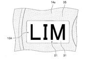
- a letter “LIM”, which is an abbreviation of Limiter, is attached to the center of the operation surface 14a of the limiter switch 10A as the symbol part 21.
- the limiter switch 10A includes an operating body 11 that is moved by being pressed by a finger, an urging member (not shown) that returns the moved operating body 11 to its original position, and a movement of the operating body 11. And a light-emitting unit 13 for detecting the pressure.
- the direction in which the operating body 11 moves by pressing is referred to as downward
- the direction in which the operating body 11 moves by the biasing member is referred to as upward.
- the operation body 11 is a transparent or translucent resin component, and is assembled to the switch unit 6.
- the operating body 11 includes a plate-shaped operating portion 14 disposed on the upper side, and a rod-shaped rod portion 15 extending downward from the back surface 14 b of the operating portion 14 and having a lower end abutting on the contact portion 12 a of the push switch 12. ing.
- the operation unit 14 of the limiter switch 10A is integrated with the operation unit 14D of the SET switch 10D, the operation unit 14E of the distance switch 10E, and the operation unit 14F of the RESUME switch 10F, and has a ring shape ( (See FIG. 3).
- the upper surface (front surface) of the operation unit 14 is an operation surface 14a pressed by the driver. On the upper surface of the operation surface 14a, a coating portion 20 formed by curing the applied paint is provided. The configuration of the covering section 20 will be described later.
- the push switch 12 includes a contact portion 12a and a main body 12b fixed to the bottom wall 6a of the switch unit 6. Further, when the contact portion 12a is pressed by the rod portion 15 of the operating body 11, the main body portion 12b transmits an electric signal to a control portion (not shown), and the limiter function is turned ON or OFF.
- the light emitting unit 13 is an LED that emits cream-colored light, and is turned on in conjunction with lighting of the exterior lamps (small light 102 and headlight 103).
- the light emitting unit 13 is fixed to the bottom wall 6a of the switch unit 6, and is arranged so as to emit light toward the back surface 14b of the operation unit 14. Therefore, the light emitted from the light emitting unit 13 enters the operation unit 14 from the back surface 14b of the operation unit 14 and passes through the surface of the operation unit 14 (operation surface 14a).
- the covering unit 20 includes a symbol unit 21 that covers a substantially central portion of the operation surface 14a, and a background unit 30 that covers all regions other than the symbol unit 21 on the operation surface 14a.
- the background portion 30 uses a cream color and is unified with the color of the interior.
- black with low brightness is used, and a color that provides a strong contrast in relation to the color of the background part 30 (cream color) is selected.
- the surface of the switch unit 6 is also cream-colored, and is unified with the interior color.
- the symbol portion 21 is formed by a combination of alphabets “L”, “I” and “M”, and is composed of a plurality of marks 22, 23 and 24. Further, the paint used for the symbol portion 21 (each mark 22, 23, 24) has a low transmittance, so that light is hardly transmitted.
- the background section 30 includes a first background section 31 adjacent to the symbol section 21 and a second background section 35 provided outside the first background section 31.
- the paint used for the first background portion 31 has a high transmittance.
- the paint used for the second background portion 35 does not transmit light or has low transmittance.
- the first background portion 31 includes an “L” background portion 32 extending along the edge of the mark 22 and surrounding the mark 22, and an “I” background portion 33 extending along the edge of the mark 23 and surrounding the mark 23. , Extending along the edge of the mark 24 and surrounding the mark 24.
- the “L” background section 32, the “I” background section 33, and the “M” background section 34 have a configuration corresponding to a “small background section” in the claims.
- the “L” background portion 32, the “I” background portion 33, and the “M” background portion 34 are continuous, and are located between the “L” background portion 32, the “I” background portion 33, and the “M” background portion 34.
- the second background portion 35 does not intervene.
- the second background portion 35 is formed in an area other than the symbol portion 21 and the first background portion 31 on the operation surface 14a.
- the limiter switch 10A vehicle operation switch
- the limiter switch 10A includes the operation body 11 having the operation surface 14a, and the cream (white) light emitting unit 13 disposed in the operation body 11;
- the operation surface 14a has a low brightness symbol portion 21 and a high brightness background portion 30 constituting the background of the symbol portion 21.
- the background portion 30 is provided along the edge of the symbol portion 21.
- the first background portion 31 and a second background portion 35 provided outside the first background portion 31.
- the symbol portion 21 and the second background portion 35 do not transmit or transmit light.
- the first background portion 31 has a high transmittance.
- the light emitting unit 13 is turned on and off in conjunction with turning on and off the exterior lamps (small light 102 and headlight 103) of the vehicle 1 arranged in the operating body 11.
- the exterior lamps (small light 102 and headlight 103) are turned on and off by an illuminometer 101 provided in the vehicle 1.
- the symbol portion 21 of the operation surface 14a looks black and the background portion 30 looks creamy.
- the brightness of the symbol portion 21 is low, the brightness of the background portion 30 is high and the contrast is strong.
- the headlight 103 is lit at night, and the light emitting unit 13 emits light correspondingly.
- the cream-colored light emitted from the light emitting unit 13 passes through the first background portion 31 having high transmittance, so that the first background portion 31 looks cream-colored.
- the symbol portion 21 and the second background portion 35 with low transmittance appear black (or dark gray) because light is not transmitted or the amount of transmitted light is extremely small. Therefore, the brightness of the first background portion 31 is high while the brightness of the symbol portion 21 is low, and the contrast is strong.
- the second background portion 35 of the limiter switch 10A cooperates with the second background portion 35C of the adjacent CANCEL switch 10C to form the first background portion 31 of the limiter switch 10A and the CANCEL switch 10C.
- the symbol part 21 of the limiter switch 10A and the symbol part 21C of the CANCEL switch 10C are visually recognized separately, and visibility is improved.
- the same effect can be obtained because the second background portion 35 of the limiter switch 10A is adjacent to the second background portion 35D of the SET switch 10D and the second background portion 35F of the RESUME switch 10F.
- the small light 102 when the small light 102 is not turned on due to the low light amount of the sun and the small light 102 is not lit, the light amount of the sun illuminating the background portion 30 of the operation surface 14 a is small, and the background portion 30 becomes dark, for example, beige. Looks like. Further, since the amount of the sun illuminating the symbol portion 21 is small, the symbol portion 21 looks blacker. Therefore, the lightness of both the symbol part 21 and the background part 30 is reduced, and the lightness difference between them is still large (the contrast between the symbol part 21 and the background part 30 is strong).
- the light emitting unit 13 when the small light 102 is turned on at dusk, the light emitting unit 13 emits light. Therefore, the cream light emitted from the light emitting unit 13 passes through the first background unit 31, and the first background unit 31 looks cream-colored.
- the symbol portion 21 has a small amount of transmitted light and looks black. Therefore, the brightness of the first background portion 31 is high while the brightness of the symbol portion 21 is low, and the contrast is strong. As described above, according to the present embodiment, it is easy to always recognize the symbol portion 21 and it is possible to use a high-brightness color for the interior.
- the light-emitting portion is turned on and off in conjunction with the turning on and off of the exterior lamp, it is possible to achieve both improved user convenience and improved visibility during twilight.
- the symbol part 21 is composed of a plurality of marks 22, 23, and 24, and the first background part 31 is composed of the marks 22, 23, and 24.
- a plurality of small background portions 32, 33, 34 provided along the edge of the plurality of small background portions 32, 33, 34, and the plurality of small background portions 32, 33, 34 are formed continuously.
- the "L" background portion 32, the "I” background portion 33, and the "M” background portion 34 illuminate integrally, and the plurality of marks 22, 23, and 24 are associated with each other. Therefore, the symbol portion 21 can be easily recognized. In other words, it is possible to avoid a possibility that the plurality of marks 22, 23, and 24 are separately and independently viewed and the symbol portion 21 does not perform its function.
- the limiter switch 10A vehicle operation switch of the embodiment is provided on the steering wheel 2. According to this, light emitted from another instrument provided on the instrument panel is unlikely to enter the operation surface 14a. Therefore, the possibility that the entire operation surface 14a shines and the contrast becomes weak can be reduced.
- the present invention is not limited to the above-described example.
- the covering part 20 formed by curing the paint is used as the symbol part 21 and the background part 30, the covering part 20 formed by curing the paint is used.
- a cover that covers the operation surface 14 a may be used.
- the operation surface 14a since the first background portion 31 only needs to transmit light, the operation surface 14a may be exposed (the covering portion 20 and the cover are not used).
- the symbol portion 21 and the background portion 30 may be formed by coloring the resin material forming the operation portion 14. In this case, it is necessary to change the transmittance for each of the parts constituting the symbol part 21, the first background part 31, and the second background part 35.
- the light transmittance of the first background portion 31 and the second background portion 35 can be reduced by changing the thickness of the paint without changing the type of the paint between the first background portion 31 and the second background portion 35. It may be changed.
- cream is used as the color of the background portion 30 in the embodiment, but a color with high brightness such as white, pale yellow (light yellow), beige (extremely light yellow to brown), and khaki (light brown) is used. And it is not particularly limited.
- the color of the symbol portion 21 in the embodiment is not particularly limited as long as a strong contrast corresponding to the background portion 30 such as dark gray can be obtained.
- the light emitting unit 13 of the embodiment emits cream-colored light, but the light emitting unit of the present invention has a strong contrast between the symbol portion 21 and the color of the light transmitted through the first background portion 31 and recognized. It is only necessary to be able to obtain white light such as white or yellow light.
- the symbol section 21 of the present embodiment is composed of a plurality of marks 22, 23 and 24, it may be composed of a single mark. Further, the mark is not limited to a character, but may be a symbol or a figure.
- a plurality of small background portions (“L” background portion 32, “I” background portion 33, and “M” background portion 34) are continuous. As shown in FIG. 11, a plurality of small background portions (“L” background portion 32A, “I” background portion 33A, and “M” background portion 34A) may be a first background portion 31A that is not continuous.
- the symbol portion 21 and the second background portion 35 have low transmittance, but may be one that can completely block light from the light emitting portion 13.
- the light emitting unit 13 is linked to turning on and off the small light 102 and the headlight 103, but may be linked to an exterior lamp such as a position lamp or a fog lamp.
Abstract
The present invention addresses the problem of providing a vehicle operation switch (10A) that facilitates recognition of a symbol (21) even when high brightness color is selected for a background (30) and a light-emitting unit emits light during a twilight period. The vehicle operation switch (10A) according to the present invention is provided with: an operation body (11) that has an operation surface (14a); and a white light-emitting unit (13) that is disposed in the operation body (11), wherein the operation surface (14a) has a symbol (21) of low brightness and a background (30) which is of high brightness and which constitutes the background of the symbol (21). The background (30) has a first background (31) which is provided along the edge of the symbol (21) and a second background (35) which is provided outside the first background (31). The first background (31) exhibits high light transmittance, whereas the symbol (21) and the second background (35) do not allow light to transmit therethrough or exhibit low light transmittance.
Description
本発明は、車両用操作スイッチ(「スイッチ」を称する場合がある)に関する。
The present invention relates to a vehicle operation switch (sometimes referred to as a “switch”).
車内には、例えばオーディオの種類を変えたり音量を調整したりするためのスイッチが複数設けられている。また、スイッチの操作面(操作体の表面)には文字や図形等のシンボル部が付され、押圧時に実行される機能を認識できる。
ス イ ッ チ A plurality of switches are provided in the vehicle, for example, for changing the type of audio and adjusting the volume. In addition, a symbol portion such as a character or a figure is attached to the operation surface of the switch (the surface of the operation body), and a function executed when the switch is pressed can be recognized.
ところで、従来のスイッチの操作面は、例えば黒色やグレーなど、明度の低い色が選択されている一方、シンボル部は、背景を構成する操作面とのコントラストが強く、シンボル部を認識し易い色、例えば白色など、明度の高い色が選択されていた。これにより、背景を構成する操作面とシンボル部のコントラストの差により視認性が確保されていた。以下、操作面においてシンボル部以外の領域を背景部という。
By the way, a low-brightness color such as black or gray is selected for the operation surface of the conventional switch, while the symbol portion has a strong contrast with the operation surface forming the background, and a color in which the symbol portion is easily recognized. For example, a color with high brightness, such as white, has been selected. As a result, visibility is ensured due to the difference in contrast between the operation surface constituting the background and the symbol portion. Hereinafter, an area other than the symbol part on the operation surface is referred to as a background part.
また、スイッチの操作体の内部には、白色系の発光部が設けられており、車内が暗い場合、発光部が発光しシンボル部が白く光る。これによれば、暗いために黒く見える背景部と白く見える(光る)シンボル部とのコントラストが強く、シンボル部を認識し易い(下記特許文献を参照)。
白色 A white light emitting section is provided inside the switch operation body. When the inside of the vehicle is dark, the light emitting section emits light and the symbol section glows white. According to this, the contrast between the background part that looks black because it is dark and the symbol part that looks white (glows) is strong, and the symbol part is easy to recognize (see Patent Document below).
近年、車両内装の美観性向上又はデザインの選択幅を広げるため、スイッチの操作面を例えば白色やクリーム色など、内装を明度の高い色にすることが検討されている。よって、操作面に関しても、背景部を内装と同じ明度の高い色とし、シンボル部を明度の低い色とすることが検討されている。
しかしながら、薄暮の時間帯に発光部が発光すると、暗くなっていない白色系の背景部を背景として、シンボル部が白く光る。よって、シンボル部と背景部とのコントラストが弱くシンボル部を認識し難い。 In recent years, in order to improve the aesthetics of the vehicle interior or to widen the range of design choices, it has been studied to make the interior of the switch a high-brightness color such as white or cream for the operation surface of the switch. Therefore, with regard to the operation surface, studies are being made on setting the background portion to have the same high-brightness color as the interior and the symbol portion to have the low-brightness color.
However, when the light emitting section emits light during the twilight time, the symbol section glows white against a white background that is not dark. Therefore, the contrast between the symbol part and the background part is weak, and it is difficult to recognize the symbol part.
そこで、本発明は、前記する背景に鑑みて創案された発明であって、背景部に明度の高い色を選択し、かつ、薄暮の時間帯に発光部が発光したとしても、シンボル部を認識し易い車両用操作スイッチを提供することを課題とする。
Therefore, the present invention has been made in view of the above-described background, and recognizes a symbol portion even when a high-brightness color is selected for the background portion and the light-emitting portion emits light during the twilight time. It is an object to provide a vehicle operation switch that is easy to operate.
前記課題を解決するための手段として、本発明に係る車両用操作スイッチは、操作面を有する操作体と、前記操作体内に配置される白色系の発光部と、を備え、前記操作面は、明度の低いシンボル部と、前記シンボル部の背景を構成し明度の高い背景部と、を有し、前記背景部は、前記シンボル部の縁沿いに設けられた第1背景部と、前記第1背景部の外側に設けられた第2背景部と、を有し、前記シンボル部と前記第2背景部は光が透過しない又は光の透過率が低い一方で、前記第1背景部は透過率が高くなっていることを特徴とする。
As means for solving the above problems, a vehicle operation switch according to the present invention includes an operation body having an operation surface, and a white light emitting unit disposed in the operation body, wherein the operation surface is A symbol portion having a low brightness, and a background portion having a high brightness that constitutes the background of the symbol portion, wherein the background portion includes a first background portion provided along an edge of the symbol portion; A second background portion provided outside a background portion, wherein the symbol portion and the second background portion do not transmit light or have low light transmittance, while the first background portion has a transmittance. Is higher.
前記発明によれば、発光部が発光した場合、第1背景部が白く光る(白く見える)。一方、シンボル部は黒く見え、シンボル部とのコントラストが強く、シンボル部を視認し易い。
According to the invention, when the light-emitting portion emits light, the first background portion shines white (appears white). On the other hand, the symbol portion looks black, the contrast with the symbol portion is strong, and the symbol portion is easily visible.
実施形態の車両用操作スイッチが適用された車両1について説明する。
図1に示すように、実施形態の車両1は、照度計101により外部の明るさを計測し、薄暗と判断した場合にスモールライト102を点灯し、さらに暗いと判断した場合にヘッドライト103を点灯するようになっている。また、車両1の室内には、進行方向を変えるためのステアリング2が設けられている。 Avehicle 1 to which the vehicle operation switch according to the embodiment is applied will be described.
As shown in FIG. 1, thevehicle 1 of the embodiment measures external brightness with an illuminometer 101, turns on a small light 102 when it is determined to be dim, and turns on a headlight 103 when it is determined that it is darker. It is lit. Further, a steering 2 for changing the traveling direction is provided in the cabin of the vehicle 1.
図1に示すように、実施形態の車両1は、照度計101により外部の明るさを計測し、薄暗と判断した場合にスモールライト102を点灯し、さらに暗いと判断した場合にヘッドライト103を点灯するようになっている。また、車両1の室内には、進行方向を変えるためのステアリング2が設けられている。 A
As shown in FIG. 1, the
図2に示すように、ステアリング2は、図示しないステアリングシャフトに連結するハブ3と、運転者により把持される環状のリム4と、ハブ3とリム4とを連結する複数のスポーク(図1では一つのみ図示)5と、を備えている。また、ステアリング2には、複数のスイッチ10を収容したスイッチユニット6が取り付けられている。
As shown in FIG. 2, the steering 2 includes a hub 3 connected to a steering shaft (not shown), an annular rim 4 gripped by a driver, and a plurality of spokes connecting the hub 3 and the rim 4 (in FIG. 1, 5 (only one is shown). Further, a switch unit 6 containing a plurality of switches 10 is attached to the steering 2.
図3に示すように、複数のスイッチ10は、押圧式のスイッチであり、その一つとして可変スピードリミッタ機構用操作スイッチ(以下「リミッタスイッチ」という)10Aが含まれている。このリミッタスイッチ10Aは、走行速度が所定速度を超えないように制限するリミッタ機能をON・OFFするためのものである。
As shown in FIG. 3, the plurality of switches 10 are push-type switches, and one of them includes an operation switch for a variable speed limiter mechanism (hereinafter, referred to as a “limiter switch”) 10A. The limiter switch 10A is for turning ON / OFF a limiter function for limiting the traveling speed so as not to exceed a predetermined speed.
また、複数のスイッチ10には、MAINスイッチ10B、CANCELスイッチ10C、SETスイッチ10D、ディスタンススイッチ10E、RESUMEスイッチ10F、並びに車線維持支援スイッチ10Gが含まれている。
MAINスイッチ10Bは、クルーズコントロール又はアクティブクルーズコントロールのシステムを起動させるためのものである。クルーズコントロールは、運転者がアクセルペダルを踏まなくても車速を一定に保つシステムである。アクティブクルーズコントロールは、運転者がアクセルペダル及びブレーキペダルを踏まなくても先行車との車間距離を設定した距離に保ちつつ追従したり又は定速走行したりするシステムである。
また、MAINスイッチ10Bの押圧後にSETスイッチ10Dを押圧すると、押圧時の車速でクルーズコントロール又はアクティブクルーズコントロールが開始(作動)する。なお、クルーズコントロールシステム又はアクティブクルーズコントロールシステムの作動中にSETスイッチ10Dを押圧すると、設定速度が下がる。
CANCELスイッチ10Cは、クルーズコントロール又はアクティブクルーズコントロールの作動を解除するためのものである。
ディスタンススイッチ10Eは、アクティブクルーズコントロールの作動中、先行車との車間距離を調整するためのものである。
また、ブレーキペダルを踏みクルーズコントロール又はアクティブクルーズコントロールが中断した場合にRESUMEスイッチ10Fを押圧すると、中断前の速度でクルーズコントロール又はアクティブクルーズコントロールの作動が再開する。なお、クルーズコントロール又はアクティブクルーズコントロールの作動中に押圧すると、設定速度が上がる。
車線維持支援スイッチ10Gは、ステアリング2の動きをアシストして左右の車線内を走行するように補助するシステムをON・OFFするためのものである。
以下、複数のスイッチ10の代表例として、リミッタスイッチ10Aを説明する。 The plurality ofswitches 10 include a MAIN switch 10B, a CANCEL switch 10C, a SET switch 10D, a distance switch 10E, a RESUME switch 10F, and a lane keeping assist switch 10G.
TheMAIN switch 10B is for activating a cruise control or active cruise control system. Cruise control is a system that keeps the vehicle speed constant without the driver depressing the accelerator pedal. Active cruise control is a system in which a driver follows the vehicle or travels at a constant speed while maintaining the inter-vehicle distance with a preceding vehicle at a set distance without stepping on an accelerator pedal and a brake pedal.
When theSET switch 10D is pressed after the MAIN switch 10B is pressed, the cruise control or active cruise control starts (operates) at the vehicle speed at the time of pressing. When the SET switch 10D is pressed while the cruise control system or the active cruise control system is operating, the set speed decreases.
The CANCELswitch 10C is for canceling the operation of the cruise control or the active cruise control.
Thedistance switch 10E is for adjusting the inter-vehicle distance with the preceding vehicle while the active cruise control is operating.
If theRESUME switch 10F is pressed when the cruise control or the active cruise control is interrupted by depressing the brake pedal, the operation of the cruise control or the active cruise control resumes at the speed before the interruption. If the button is pressed during the operation of the cruise control or the active cruise control, the set speed increases.
The lane keepingassist switch 10G is for turning on / off a system for assisting the movement of the steering wheel 2 to assist in traveling in the left and right lanes.
Hereinafter, alimiter switch 10A will be described as a representative example of the plurality of switches 10.
MAINスイッチ10Bは、クルーズコントロール又はアクティブクルーズコントロールのシステムを起動させるためのものである。クルーズコントロールは、運転者がアクセルペダルを踏まなくても車速を一定に保つシステムである。アクティブクルーズコントロールは、運転者がアクセルペダル及びブレーキペダルを踏まなくても先行車との車間距離を設定した距離に保ちつつ追従したり又は定速走行したりするシステムである。
また、MAINスイッチ10Bの押圧後にSETスイッチ10Dを押圧すると、押圧時の車速でクルーズコントロール又はアクティブクルーズコントロールが開始(作動)する。なお、クルーズコントロールシステム又はアクティブクルーズコントロールシステムの作動中にSETスイッチ10Dを押圧すると、設定速度が下がる。
CANCELスイッチ10Cは、クルーズコントロール又はアクティブクルーズコントロールの作動を解除するためのものである。
ディスタンススイッチ10Eは、アクティブクルーズコントロールの作動中、先行車との車間距離を調整するためのものである。
また、ブレーキペダルを踏みクルーズコントロール又はアクティブクルーズコントロールが中断した場合にRESUMEスイッチ10Fを押圧すると、中断前の速度でクルーズコントロール又はアクティブクルーズコントロールの作動が再開する。なお、クルーズコントロール又はアクティブクルーズコントロールの作動中に押圧すると、設定速度が上がる。
車線維持支援スイッチ10Gは、ステアリング2の動きをアシストして左右の車線内を走行するように補助するシステムをON・OFFするためのものである。
以下、複数のスイッチ10の代表例として、リミッタスイッチ10Aを説明する。 The plurality of
The
When the
The CANCEL
The
If the
The lane keeping
Hereinafter, a
図4に示すように、リミッタスイッチ10Aの操作面14aの中央部には、シンボル部21としてリミッタ(Limiter)の略語である「LIM」の文字が付されている。
文字 As shown in FIG. 4, a letter “LIM”, which is an abbreviation of Limiter, is attached to the center of the operation surface 14a of the limiter switch 10A as the symbol part 21.
図5に示すように、リミッタスイッチ10Aは、指で押圧されて移動する操作体11と、移動した操作体11を元の位置に復帰させる付勢部材(不図示)と、操作体11の移動を検知するプッシュスイッチ12と、発光部13と、を備えている。
なお、説明の都合上、押圧により操作体11が移動する方向を下方、付勢部材により操作体11が移動する方向を上方と称する。 As shown in FIG. 5, thelimiter switch 10A includes an operating body 11 that is moved by being pressed by a finger, an urging member (not shown) that returns the moved operating body 11 to its original position, and a movement of the operating body 11. And a light-emitting unit 13 for detecting the pressure.
For convenience of description, the direction in which theoperating body 11 moves by pressing is referred to as downward, and the direction in which the operating body 11 moves by the biasing member is referred to as upward.
なお、説明の都合上、押圧により操作体11が移動する方向を下方、付勢部材により操作体11が移動する方向を上方と称する。 As shown in FIG. 5, the
For convenience of description, the direction in which the
操作体11は、透明又は透光性を有する樹脂製の部品であり、スイッチユニット6に組み付けられている。
操作体11は、上側に配置された板状の操作部14と、操作部14の背面14bから下方に延出し下端がプッシュスイッチ12の接触部12aと当接する棒状の棒状部15と、を備えている。なお、リミッタスイッチ10Aの操作部14は、SETスイッチ10Dの操作部14Dと、ディスタンススイッチ10Eの操作部14Eと、RESUMEスイッチ10Fの操作部14Fと一体になっており、リング状を呈している(図3参照)。
また、操作部14の上面(表面)は、運転者に押圧される操作面14aとなっている。操作面14aの上面には、塗布された塗料が硬化して成る被覆部20が設けられている。なお、被覆部20の構成については後述する。 Theoperation body 11 is a transparent or translucent resin component, and is assembled to the switch unit 6.
Theoperating body 11 includes a plate-shaped operating portion 14 disposed on the upper side, and a rod-shaped rod portion 15 extending downward from the back surface 14 b of the operating portion 14 and having a lower end abutting on the contact portion 12 a of the push switch 12. ing. The operation unit 14 of the limiter switch 10A is integrated with the operation unit 14D of the SET switch 10D, the operation unit 14E of the distance switch 10E, and the operation unit 14F of the RESUME switch 10F, and has a ring shape ( (See FIG. 3).
The upper surface (front surface) of theoperation unit 14 is an operation surface 14a pressed by the driver. On the upper surface of the operation surface 14a, a coating portion 20 formed by curing the applied paint is provided. The configuration of the covering section 20 will be described later.
操作体11は、上側に配置された板状の操作部14と、操作部14の背面14bから下方に延出し下端がプッシュスイッチ12の接触部12aと当接する棒状の棒状部15と、を備えている。なお、リミッタスイッチ10Aの操作部14は、SETスイッチ10Dの操作部14Dと、ディスタンススイッチ10Eの操作部14Eと、RESUMEスイッチ10Fの操作部14Fと一体になっており、リング状を呈している(図3参照)。
また、操作部14の上面(表面)は、運転者に押圧される操作面14aとなっている。操作面14aの上面には、塗布された塗料が硬化して成る被覆部20が設けられている。なお、被覆部20の構成については後述する。 The
The
The upper surface (front surface) of the
プッシュスイッチ12は、接触部12aと、スイッチユニット6の底壁6aに固定される本体部12bとを備えている。また、本体部12bは、操作体11の棒状部15により接触部12aが押圧された際、図示しない制御部に電気信号を送信し、リミッタ機能がONされたり、OFFされたりする。
The push switch 12 includes a contact portion 12a and a main body 12b fixed to the bottom wall 6a of the switch unit 6. Further, when the contact portion 12a is pressed by the rod portion 15 of the operating body 11, the main body portion 12b transmits an electric signal to a control portion (not shown), and the limiter function is turned ON or OFF.
発光部13は、クリーム色の光を発するLEDであり、外装ランプ(スモールライト102及びヘッドライト103)の点灯と連動して点灯するようになっている。また、発光部13は、スイッチユニット6の底壁6aに固定され、操作部14の背面14bに向って光を照射するように配置されている。よって、発光部13から発する光は、操作部14の背面14bから操作部14内に入射し、操作部14の表面(操作面14a)側に透過する。
(4) The light emitting unit 13 is an LED that emits cream-colored light, and is turned on in conjunction with lighting of the exterior lamps (small light 102 and headlight 103). The light emitting unit 13 is fixed to the bottom wall 6a of the switch unit 6, and is arranged so as to emit light toward the back surface 14b of the operation unit 14. Therefore, the light emitted from the light emitting unit 13 enters the operation unit 14 from the back surface 14b of the operation unit 14 and passes through the surface of the operation unit 14 (operation surface 14a).
図4に示すように、被覆部20は、操作面14aの略中央部を被覆するシンボル部21と、操作面14aにおいてシンボル部21以外の領域全てを覆う背景部30と、を備えている。
背景部30は、クリーム色が使用され、内装の色と統一されている。また、シンボル部21には、明度の低い黒色が使用され、背景部30の色(クリーム色)との関係で強いコントラストが得られる色が選択されている。なお、スイッチユニット6の表面もクリーム色が使用され、内装の色と統一されている。 As shown in FIG. 4, the coveringunit 20 includes a symbol unit 21 that covers a substantially central portion of the operation surface 14a, and a background unit 30 that covers all regions other than the symbol unit 21 on the operation surface 14a.
Thebackground portion 30 uses a cream color and is unified with the color of the interior. For the symbol part 21, black with low brightness is used, and a color that provides a strong contrast in relation to the color of the background part 30 (cream color) is selected. The surface of the switch unit 6 is also cream-colored, and is unified with the interior color.
背景部30は、クリーム色が使用され、内装の色と統一されている。また、シンボル部21には、明度の低い黒色が使用され、背景部30の色(クリーム色)との関係で強いコントラストが得られる色が選択されている。なお、スイッチユニット6の表面もクリーム色が使用され、内装の色と統一されている。 As shown in FIG. 4, the covering
The
シンボル部21は、アルファベットの「L」と「I」と「M」との組み合わせてなり、複数のマーク22,23,24から構成されている。また、シンボル部21(各マーク22,23,24)に使用される塗料は、透過率が低いものが使用され、光が透過し難くなっている。
The symbol portion 21 is formed by a combination of alphabets “L”, “I” and “M”, and is composed of a plurality of marks 22, 23 and 24. Further, the paint used for the symbol portion 21 (each mark 22, 23, 24) has a low transmittance, so that light is hardly transmitted.
背景部30は、シンボル部21に隣接する第1背景部31と、第1背景部31の外側に設けられた第2背景部35と、を備えている。第1背景部31に使用される塗料は、透過率が高いものが使用されている。一方で、第2背景部35に使用される塗料は、光が透過しない又は透過率が低いものが使用されている。
The background section 30 includes a first background section 31 adjacent to the symbol section 21 and a second background section 35 provided outside the first background section 31. The paint used for the first background portion 31 has a high transmittance. On the other hand, the paint used for the second background portion 35 does not transmit light or has low transmittance.
第1背景部31は、マーク22の縁に沿って延在しマーク22を囲む「L」背景部32と、マーク23の縁に沿って延在しマーク23を囲む「I」背景部33と、マーク24の縁に沿って延在しマーク24を囲む「M」背景部34と、を備えている。なお、「L」背景部32、「I」背景部33、「M」背景部34は、請求項の「小背景部」に相当する構成である。
「L」背景部32と「I」背景部33と「M」背景部34は連続しており、「L」背景部32と「I」背景部33と「M」背景部34との間に第2背景部35が介在しないようになっている。 Thefirst background portion 31 includes an “L” background portion 32 extending along the edge of the mark 22 and surrounding the mark 22, and an “I” background portion 33 extending along the edge of the mark 23 and surrounding the mark 23. , Extending along the edge of the mark 24 and surrounding the mark 24. The “L” background section 32, the “I” background section 33, and the “M” background section 34 have a configuration corresponding to a “small background section” in the claims.
The “L”background portion 32, the “I” background portion 33, and the “M” background portion 34 are continuous, and are located between the “L” background portion 32, the “I” background portion 33, and the “M” background portion 34. The second background portion 35 does not intervene.
「L」背景部32と「I」背景部33と「M」背景部34は連続しており、「L」背景部32と「I」背景部33と「M」背景部34との間に第2背景部35が介在しないようになっている。 The
The “L”
第2背景部35は、操作面14aにおけるシンボル部21及び第1背景部31以外の領域に形成されている。
The second background portion 35 is formed in an area other than the symbol portion 21 and the first background portion 31 on the operation surface 14a.
以上、実施形態のリミッタスイッチ10A(車両用操作スイッチ)は、操作面14aを有する操作体11と、前記操作体11内に配置されるクリーム色(白色系)の発光部13と、を備え、前記操作面14aは、明度の低いシンボル部21と、前記シンボル部21の背景を構成し明度の高い背景部30と、を有し、前記背景部30は、前記シンボル部21の縁沿いに設けられた第1背景部31と、前記第1背景部31の外側に設けられた第2背景部35と、を有し、前記シンボル部21と前記第2背景部35は光が透過しない又は光の透過率が低い一方で、前記第1背景部31は透過率が高くなっている。また、前記発光部13は、前記操作体11内に配置され車両1の外装ランプ(スモールライト102及びヘッドライト103)の点消灯に連動して点消灯する。また、前記外装ランプ(スモールライト102及びヘッドライト103)は、前記車両1に設けられた照度計101により点消灯が切り替わる。
As described above, the limiter switch 10A (vehicle operation switch) of the embodiment includes the operation body 11 having the operation surface 14a, and the cream (white) light emitting unit 13 disposed in the operation body 11; The operation surface 14a has a low brightness symbol portion 21 and a high brightness background portion 30 constituting the background of the symbol portion 21. The background portion 30 is provided along the edge of the symbol portion 21. The first background portion 31 and a second background portion 35 provided outside the first background portion 31. The symbol portion 21 and the second background portion 35 do not transmit or transmit light. , The first background portion 31 has a high transmittance. The light emitting unit 13 is turned on and off in conjunction with turning on and off the exterior lamps (small light 102 and headlight 103) of the vehicle 1 arranged in the operating body 11. The exterior lamps (small light 102 and headlight 103) are turned on and off by an illuminometer 101 provided in the vehicle 1.
上記構成によれば、図6に示すように、太陽の光量が多い昼間は、操作面14aのシンボル部21は黒く見え、背景部30はクリーム色に見える。よって、シンボル部21の明度が低い一方で背景部30の明度が高く、コントラストが強い。
According to the above configuration, as shown in FIG. 6, in the daytime when the amount of sun light is large, the symbol portion 21 of the operation surface 14a looks black and the background portion 30 looks creamy. Thus, while the brightness of the symbol portion 21 is low, the brightness of the background portion 30 is high and the contrast is strong.
図7に示すように、夜間は、ヘッドライト103が点灯するため、これに対応して発光部13は発光する。また、発光部13から発せられたクリーム色の光は、透過率の高い第1背景部31を透過するため、第1背景部31がクリーム色に見える。一方で、透過率が低いシンボル部21と第2背景部35は、光が透過しない又は透過する光量が極めて少ないため黒色(若しくは濃いグレー)に見える。よって、シンボル部21の明度が低い一方で第1背景部31の明度が高く、コントラストが強い。
(7) As shown in FIG. 7, the headlight 103 is lit at night, and the light emitting unit 13 emits light correspondingly. In addition, the cream-colored light emitted from the light emitting unit 13 passes through the first background portion 31 having high transmittance, so that the first background portion 31 looks cream-colored. On the other hand, the symbol portion 21 and the second background portion 35 with low transmittance appear black (or dark gray) because light is not transmitted or the amount of transmitted light is extremely small. Therefore, the brightness of the first background portion 31 is high while the brightness of the symbol portion 21 is low, and the contrast is strong.
また、図8に示すように、リミッタスイッチ10Aの第2背景部35は、隣接するCANCELスイッチ10Cの第2背景部35Cと協働して、リミッタスイッチ10Aの第1背景部31とCANCELスイッチ10Cの第1背景部31Cとを離間させている。よって、リミッタスイッチ10Aのシンボル部21と、CANCELスイッチ10Cのシンボル部21Cとが切り離して視認され、視認性が向上する。
なお、リミッタスイッチ10Aの第2背景部35は、SETスイッチ10Dの第2背景部35DやRESUMEスイッチ10Fの第2背景部35Fとも隣接していることから同様な効果が得られる。 As shown in FIG. 8, thesecond background portion 35 of the limiter switch 10A cooperates with the second background portion 35C of the adjacent CANCEL switch 10C to form the first background portion 31 of the limiter switch 10A and the CANCEL switch 10C. Are separated from the first background portion 31C. Therefore, the symbol part 21 of the limiter switch 10A and the symbol part 21C of the CANCEL switch 10C are visually recognized separately, and visibility is improved.
The same effect can be obtained because thesecond background portion 35 of the limiter switch 10A is adjacent to the second background portion 35D of the SET switch 10D and the second background portion 35F of the RESUME switch 10F.
なお、リミッタスイッチ10Aの第2背景部35は、SETスイッチ10Dの第2背景部35DやRESUMEスイッチ10Fの第2背景部35Fとも隣接していることから同様な効果が得られる。 As shown in FIG. 8, the
The same effect can be obtained because the
図9に示すように、太陽の光量が少ない薄暮であってスモールライト102が点灯していない場合、操作面14aの背景部30を照らす太陽の光量が少なく、背景部30が暗くなり例えばベージュ色に見える。また、シンボル部21を照らす太陽の光量も少ないことから、シンボル部21は、より黒く見える。よって、シンボル部21及び背景部30は、両方とも明度が低下し、両者の明度差は依然として大きい(シンボル部21と背景部30のコントラストが強い)。
As shown in FIG. 9, when the small light 102 is not turned on due to the low light amount of the sun and the small light 102 is not lit, the light amount of the sun illuminating the background portion 30 of the operation surface 14 a is small, and the background portion 30 becomes dark, for example, beige. Looks like. Further, since the amount of the sun illuminating the symbol portion 21 is small, the symbol portion 21 looks blacker. Therefore, the lightness of both the symbol part 21 and the background part 30 is reduced, and the lightness difference between them is still large (the contrast between the symbol part 21 and the background part 30 is strong).
図10に示すように、薄暮であってスモールライト102が点灯した場合、発光部13が発光する。よって、発光部13から発せられたクリーム色の光が第1背景部31を透過し、第1背景部31がクリーム色に見える。一方で、シンボル部21は、透過する光量が少なく黒く見える。よって、シンボル部21の明度が低い一方で第1背景部31の明度が高く、コントラストが強い。
以上から、本実施形態によれば、常時シンボル部21を認識し易く、内装に明度の高い色を用いることが可能となる。 As shown in FIG. 10, when thesmall light 102 is turned on at dusk, the light emitting unit 13 emits light. Therefore, the cream light emitted from the light emitting unit 13 passes through the first background unit 31, and the first background unit 31 looks cream-colored. On the other hand, the symbol portion 21 has a small amount of transmitted light and looks black. Therefore, the brightness of the first background portion 31 is high while the brightness of the symbol portion 21 is low, and the contrast is strong.
As described above, according to the present embodiment, it is easy to always recognize thesymbol portion 21 and it is possible to use a high-brightness color for the interior.
以上から、本実施形態によれば、常時シンボル部21を認識し易く、内装に明度の高い色を用いることが可能となる。 As shown in FIG. 10, when the
As described above, according to the present embodiment, it is easy to always recognize the
また、外装ランプの点消灯に連動して発光部が点消灯するため、ユーザーの利便性が向上と薄暮の時間帯の視認性向上の両立を図ることができる。
た め Since the light-emitting portion is turned on and off in conjunction with the turning on and off of the exterior lamp, it is possible to achieve both improved user convenience and improved visibility during twilight.
また、ドライバが意図せずに発光部13が発光しても(スモールライト102の点灯により発光部13が点灯しても)シンボル部21を認識できるため、利便性が高い。
(4) Even if the light emitting unit 13 emits light unintentionally by the driver (even if the light emitting unit 13 is turned on by the lighting of the small light 102), the symbol unit 21 can be recognized, so that the convenience is high.
また、実施形態のリミッタスイッチ10A(車両用操作スイッチ)において、前記シンボル部21は、複数のマーク22,23,24から構成され、前記第1背景部31は、前記各マーク22,23,24の縁沿いに設けられた複数の小背景部32,33,34から構成され、前記複数の小背景部32,33,34は、連続して形成されている。
これによれば、図5このため、「L」背景部32、「I」背景部33、「M」背景部34が一体に光り、複数のマーク22,23,24のそれぞれが関連付けして見られ、シンボル部21を認識し易い。言い換えると、複数のマーク22,23,24のそれぞれが別個独立に見られてシンボル部21が機能を発揮しないおそれを回避できる。 In thelimiter switch 10A (operation switch for a vehicle) of the embodiment, the symbol part 21 is composed of a plurality of marks 22, 23, and 24, and the first background part 31 is composed of the marks 22, 23, and 24. And a plurality of small background portions 32, 33, 34 provided along the edge of the plurality of small background portions 32, 33, 34, and the plurality of small background portions 32, 33, 34 are formed continuously.
According to FIG. 5, the "L"background portion 32, the "I" background portion 33, and the "M" background portion 34 illuminate integrally, and the plurality of marks 22, 23, and 24 are associated with each other. Therefore, the symbol portion 21 can be easily recognized. In other words, it is possible to avoid a possibility that the plurality of marks 22, 23, and 24 are separately and independently viewed and the symbol portion 21 does not perform its function.
これによれば、図5このため、「L」背景部32、「I」背景部33、「M」背景部34が一体に光り、複数のマーク22,23,24のそれぞれが関連付けして見られ、シンボル部21を認識し易い。言い換えると、複数のマーク22,23,24のそれぞれが別個独立に見られてシンボル部21が機能を発揮しないおそれを回避できる。 In the
According to FIG. 5, the "L"
また、実施形態のリミッタスイッチ10A(車両用操作スイッチ)は、ステアリング2に設置されていることを特徴とする。これによれば、インストルメントパネルに設けられた他の計器から発せられる光が操作面14aに入射し難い。よって、操作面14a全体が光りコントラストが弱くなるおそれを低減できる。
The limiter switch 10A (vehicle operation switch) of the embodiment is provided on the steering wheel 2. According to this, light emitted from another instrument provided on the instrument panel is unlikely to enter the operation surface 14a. Therefore, the possibility that the entire operation surface 14a shines and the contrast becomes weak can be reduced.
以上、実施形態について説明したが、本発明は上記した例に限定されない。
実施形態では、シンボル部21及び背景部30を構成するものとして、塗料を硬化して成る被覆部20を用いているが、操作面14aを覆うカバーを用いてもよい。また、第1背景部31については、光を透過できればよいため、操作面14aが露出している(被覆部20やカバーを用いていない)状態であってもよい。
若しくは、操作部14を構成する樹脂材料に着色し、シンボル部21及び背景部30を形成するようにしてもよい。この場合においては、シンボル部21、第1背景部31及び第2背景部35を構成する部分毎に透過率を変更する必要がある。
若しくは、第1背景部31と第2背景部35とで塗料の種類は変更せず、塗料の厚さを異ならせることにより、第1背景部31及び第2背景部35の光の透過率を変更するものであってもよい。 The embodiment has been described above, but the present invention is not limited to the above-described example.
In the embodiment, as thesymbol part 21 and the background part 30, the covering part 20 formed by curing the paint is used. However, a cover that covers the operation surface 14 a may be used. In addition, since the first background portion 31 only needs to transmit light, the operation surface 14a may be exposed (the covering portion 20 and the cover are not used).
Alternatively, thesymbol portion 21 and the background portion 30 may be formed by coloring the resin material forming the operation portion 14. In this case, it is necessary to change the transmittance for each of the parts constituting the symbol part 21, the first background part 31, and the second background part 35.
Alternatively, the light transmittance of thefirst background portion 31 and the second background portion 35 can be reduced by changing the thickness of the paint without changing the type of the paint between the first background portion 31 and the second background portion 35. It may be changed.
実施形態では、シンボル部21及び背景部30を構成するものとして、塗料を硬化して成る被覆部20を用いているが、操作面14aを覆うカバーを用いてもよい。また、第1背景部31については、光を透過できればよいため、操作面14aが露出している(被覆部20やカバーを用いていない)状態であってもよい。
若しくは、操作部14を構成する樹脂材料に着色し、シンボル部21及び背景部30を形成するようにしてもよい。この場合においては、シンボル部21、第1背景部31及び第2背景部35を構成する部分毎に透過率を変更する必要がある。
若しくは、第1背景部31と第2背景部35とで塗料の種類は変更せず、塗料の厚さを異ならせることにより、第1背景部31及び第2背景部35の光の透過率を変更するものであってもよい。 The embodiment has been described above, but the present invention is not limited to the above-described example.
In the embodiment, as the
Alternatively, the
Alternatively, the light transmittance of the
また、実施形態の背景部30の色彩として、クリーム色が用いられているが、白色、淡黄色(薄い黄色)、ベージュ(極めて薄い黄色ないし茶色)、カーキ(淡い茶色)などの明度の高い色であってもよく、特に限定されない。
In addition, cream is used as the color of the background portion 30 in the embodiment, but a color with high brightness such as white, pale yellow (light yellow), beige (extremely light yellow to brown), and khaki (light brown) is used. And it is not particularly limited.
また、実施形態のシンボル部21の色彩として、黒色が用いられているが、濃いグレーなど、背景部30に対応して強いコントラストを得ることができれば、特に限定されない。
{Circle around (3)} Although black is used as the color of the symbol portion 21 in the embodiment, the color is not particularly limited as long as a strong contrast corresponding to the background portion 30 such as dark gray can be obtained.
また、実施形態の発光部13は、クリーム色の光を発しているが、本発明の発光部は、第1背景部31を透過して認識される光の色がシンボル部21と強いコントラストを得ることができればよく、例えば白色や黄色の光など、白色系の光を発することができればよい。
In addition, the light emitting unit 13 of the embodiment emits cream-colored light, but the light emitting unit of the present invention has a strong contrast between the symbol portion 21 and the color of the light transmitted through the first background portion 31 and recognized. It is only necessary to be able to obtain white light such as white or yellow light.
また、本実施形態のシンボル部21は、複数のマーク22,23,24から構成されているが、単一のマークから構成されてもよい。また、マークは、文字に限定されず、記号や図などでもよい。
{Circle around (2)} Although the symbol section 21 of the present embodiment is composed of a plurality of marks 22, 23 and 24, it may be composed of a single mark. Further, the mark is not limited to a character, but may be a symbol or a figure.
また、実施形態の第1背景部31において、複数の小背景部(「L」背景部32,「I」背景部33,「M」背景部34)が連続していたが、本発明は、図11に示すように、複数の小背景部(「L」背景部32A,「I」背景部33A,「M」背景部34A)が連続していない第1背景部31Aであってもよい。
In the first background portion 31 of the embodiment, a plurality of small background portions (“L” background portion 32, “I” background portion 33, and “M” background portion 34) are continuous. As shown in FIG. 11, a plurality of small background portions (“L” background portion 32A, “I” background portion 33A, and “M” background portion 34A) may be a first background portion 31A that is not continuous.
また、シンボル部21と第2背景部35は透過率が低くなっているが発光部13の光を完全に遮断できるものであってもよい。
The symbol portion 21 and the second background portion 35 have low transmittance, but may be one that can completely block light from the light emitting portion 13.
また、発光部13は、スモールライト102やヘッドライト103の点消灯に連動しているが、ポジションランプやフォグランプなどの外装ランプに連動するようにしてもよい。
The light emitting unit 13 is linked to turning on and off the small light 102 and the headlight 103, but may be linked to an exterior lamp such as a position lamp or a fog lamp.
1 車両
2 ステアリング
6 スイッチユニット
10 スイッチ(車両用操作スイッチ)
10A 可変スピードリミッタ機構用操作スイッチ
10B MAINスイッチ
10C CANCELスイッチ
10D SETスイッチ
10E ディスタンススイッチ
10F RES(Resume)スイッチ
10G 車線維持支援スイッチ
11 操作体
13 発光部
14 操作部
14a 操作面
15 棒状部
20 被覆部
21 シンボル部
22,23,24 マーク
30 背景部
31 第1背景部
32 「L」背景部(小背景部)
33 「I」背景部(小背景部)
34 「M」背景部(小背景部)
35 第2背景部Reference Signs List 1 vehicle 2 steering 6 switch unit 10 switch (operation switch for vehicle)
Reference Signs List 10A Variable speed limiter mechanism operation switch 10B MAIN switch 10C CANCEL switch 10D SET switch 10E Distance switch 10F RES (Resume) switch 10G Lane keeping support switch 11 Operating body 13 Light emitting section 14 Operating section 14a Operation surface 15 Rod section 20 Covering section 21 Symbol part 22, 23, 24 mark 30 background part 31 first background part 32 "L" background part (small background part)
33 "I" background part (small background part)
34 "M" background part (small background part)
35 Second background section
2 ステアリング
6 スイッチユニット
10 スイッチ(車両用操作スイッチ)
10A 可変スピードリミッタ機構用操作スイッチ
10B MAINスイッチ
10C CANCELスイッチ
10D SETスイッチ
10E ディスタンススイッチ
10F RES(Resume)スイッチ
10G 車線維持支援スイッチ
11 操作体
13 発光部
14 操作部
14a 操作面
15 棒状部
20 被覆部
21 シンボル部
22,23,24 マーク
30 背景部
31 第1背景部
32 「L」背景部(小背景部)
33 「I」背景部(小背景部)
34 「M」背景部(小背景部)
35 第2背景部
33 "I" background part (small background part)
34 "M" background part (small background part)
35 Second background section
Claims (5)
- 操作面を有する操作体と、前記操作体内に配置される白色系の発光部と、を備え、
前記操作面は、明度の低いシンボル部と、前記シンボル部の背景を構成し明度の高い背景部と、を有し、
前記背景部は、前記シンボル部の縁沿いに設けられた第1背景部と、前記第1背景部の外側に設けられた第2背景部と、を有し、
前記シンボル部と前記第2背景部は光が透過しない又は光の透過率が低い一方で、前記第1背景部は透過率が高くなっていることを特徴とする車両用操作スイッチ。 An operating body having an operating surface, and a white light emitting unit disposed in the operating body,
The operation surface has a low-brightness symbol portion, and a high-brightness background portion forming a background of the symbol portion,
The background section has a first background section provided along an edge of the symbol section, and a second background section provided outside the first background section.
The operation switch for a vehicle, wherein the symbol portion and the second background portion do not transmit light or have low light transmittance, while the first background portion has high transmittance. - 前記シンボル部は、複数のマークから構成され、
前記第1背景部は、前記各マークの縁沿いに設けられた複数の小背景部から構成され、
前記複数の小背景部は、連続して形成されていることを特徴とする請求項1に記載の車両用操作スイッチ。 The symbol portion is composed of a plurality of marks,
The first background portion includes a plurality of small background portions provided along an edge of each mark,
The vehicle operation switch according to claim 1, wherein the plurality of small background portions are formed continuously. - 前記発光部は、前記操作体内に配置され車両の外装ランプの点消灯に連動して点消灯することを特徴とする請求項1又は請求項2に記載の車両用操作スイッチ。 3. The vehicle operation switch according to claim 1, wherein the light emitting unit is arranged in the operation body and turns on and off in synchronization with turning on and off an exterior lamp of the vehicle. 4.
- 前記外装ランプは、前記車両に設けられた照度計により点消灯が切り替わることを特徴とする請求項3に記載の車両用操作スイッチ。 The vehicle operation switch according to claim 3, wherein the exterior lamp is switched on and off by an illuminometer provided on the vehicle.
- ステアリングに設置されていることを特徴とする請求項1から請求項4のいずれか1項に記載の車両用操作スイッチ。
The vehicle operation switch according to any one of claims 1 to 4, wherein the operation switch is mounted on a steering wheel.
Priority Applications (1)
| Application Number | Priority Date | Filing Date | Title |
|---|---|---|---|
| PCT/JP2018/035986 WO2020065835A1 (en) | 2018-09-27 | 2018-09-27 | Vehicle operation switch |
Applications Claiming Priority (1)
| Application Number | Priority Date | Filing Date | Title |
|---|---|---|---|
| PCT/JP2018/035986 WO2020065835A1 (en) | 2018-09-27 | 2018-09-27 | Vehicle operation switch |
Publications (1)
| Publication Number | Publication Date |
|---|---|
| WO2020065835A1 true WO2020065835A1 (en) | 2020-04-02 |
Family
ID=69952960
Family Applications (1)
| Application Number | Title | Priority Date | Filing Date |
|---|---|---|---|
| PCT/JP2018/035986 WO2020065835A1 (en) | 2018-09-27 | 2018-09-27 | Vehicle operation switch |
Country Status (1)
| Country | Link |
|---|---|
| WO (1) | WO2020065835A1 (en) |
Citations (4)
| Publication number | Priority date | Publication date | Assignee | Title |
|---|---|---|---|---|
| JP2001143559A (en) * | 1999-11-15 | 2001-05-25 | Auto Network Gijutsu Kenkyusho:Kk | On-board driving device |
| JP2003203535A (en) * | 2002-01-07 | 2003-07-18 | Fujitec Co Ltd | Operation button |
| JP2004002008A (en) * | 2002-03-29 | 2004-01-08 | Toshiba Elevator Co Ltd | Operation button device of elevator |
| JP2012238432A (en) * | 2011-05-10 | 2012-12-06 | Calsonic Kansei Corp | Switching apparatus |
-
2018
- 2018-09-27 WO PCT/JP2018/035986 patent/WO2020065835A1/en active Application Filing
Patent Citations (4)
| Publication number | Priority date | Publication date | Assignee | Title |
|---|---|---|---|---|
| JP2001143559A (en) * | 1999-11-15 | 2001-05-25 | Auto Network Gijutsu Kenkyusho:Kk | On-board driving device |
| JP2003203535A (en) * | 2002-01-07 | 2003-07-18 | Fujitec Co Ltd | Operation button |
| JP2004002008A (en) * | 2002-03-29 | 2004-01-08 | Toshiba Elevator Co Ltd | Operation button device of elevator |
| JP2012238432A (en) * | 2011-05-10 | 2012-12-06 | Calsonic Kansei Corp | Switching apparatus |
Similar Documents
| Publication | Publication Date | Title |
|---|---|---|
| US11794579B2 (en) | Driving system for automated driving with a steering wheel display | |
| US10766409B2 (en) | Vehicle light assembly having strobe light | |
| US9616812B2 (en) | Light emission structure for indication symbol in interior space of vehicle | |
| US8547017B2 (en) | Vehicle dome and reading light | |
| US9889791B2 (en) | Illuminated badge for a vehicle | |
| US20050099287A1 (en) | Indicator system for vehicles | |
| JP2009163966A (en) | Paddle switch for steering wheel | |
| US20110232408A1 (en) | Device and method for the control of an automatic transmission and of a motor vehicle | |
| JP2007063981A (en) | Door handle | |
| CN104163143B (en) | For the lens device of motor vehicle | |
| US8888339B2 (en) | Light arrangement, method for operating a light arrangement and a motor vehicle | |
| CN107357002A (en) | A kind of light guide combination and the car light with light guide combination | |
| WO2020065835A1 (en) | Vehicle operation switch | |
| US6650058B1 (en) | Vehicle head light or auxiliary light assembly | |
| CN213442283U (en) | Driver airbag with active feedback function | |
| EP1593549A3 (en) | Illumination device for vehicles | |
| EP0702634B1 (en) | Compact control unit for motor vehicles, particularly trucks | |
| US10293744B1 (en) | Automatic turn-signal system | |
| JP5257378B2 (en) | Light control system for vehicle | |
| US8350171B2 (en) | Function switch on handle of motorcycle | |
| CN220662396U (en) | Chromed surface emotion lamp device for automobile | |
| CN211778928U (en) | Gear shifting ball head | |
| JP2001057123A (en) | Switch arranged on steering wheel | |
| JP2712762B2 (en) | Display device for vehicles | |
| KR200343121Y1 (en) | A lighting shoes |
Legal Events
| Date | Code | Title | Description |
|---|---|---|---|
| 121 | Ep: the epo has been informed by wipo that ep was designated in this application |
Ref document number: 18934855 Country of ref document: EP Kind code of ref document: A1 |
|
| NENP | Non-entry into the national phase |
Ref country code: DE |
|
| 122 | Ep: pct application non-entry in european phase |
Ref document number: 18934855 Country of ref document: EP Kind code of ref document: A1 |
|
| NENP | Non-entry into the national phase |
Ref country code: JP |