WO2020059868A1 - Light adjusting device - Google Patents
Light adjusting device Download PDFInfo
- Publication number
- WO2020059868A1 WO2020059868A1 PCT/JP2019/037083 JP2019037083W WO2020059868A1 WO 2020059868 A1 WO2020059868 A1 WO 2020059868A1 JP 2019037083 W JP2019037083 W JP 2019037083W WO 2020059868 A1 WO2020059868 A1 WO 2020059868A1
- Authority
- WO
- WIPO (PCT)
- Prior art keywords
- light control
- voltage
- unit
- control unit
- units
- Prior art date
Links
Images


Classifications
-
- G—PHYSICS
- G02—OPTICS
- G02F—OPTICAL DEVICES OR ARRANGEMENTS FOR THE CONTROL OF LIGHT BY MODIFICATION OF THE OPTICAL PROPERTIES OF THE MEDIA OF THE ELEMENTS INVOLVED THEREIN; NON-LINEAR OPTICS; FREQUENCY-CHANGING OF LIGHT; OPTICAL LOGIC ELEMENTS; OPTICAL ANALOGUE/DIGITAL CONVERTERS
- G02F1/00—Devices or arrangements for the control of the intensity, colour, phase, polarisation or direction of light arriving from an independent light source, e.g. switching, gating or modulating; Non-linear optics
- G02F1/01—Devices or arrangements for the control of the intensity, colour, phase, polarisation or direction of light arriving from an independent light source, e.g. switching, gating or modulating; Non-linear optics for the control of the intensity, phase, polarisation or colour
- G02F1/13—Devices or arrangements for the control of the intensity, colour, phase, polarisation or direction of light arriving from an independent light source, e.g. switching, gating or modulating; Non-linear optics for the control of the intensity, phase, polarisation or colour based on liquid crystals, e.g. single liquid crystal display cells
- G02F1/133—Constructional arrangements; Operation of liquid crystal cells; Circuit arrangements
- G02F1/13306—Circuit arrangements or driving methods for the control of single liquid crystal cells
-
- E—FIXED CONSTRUCTIONS
- E06—DOORS, WINDOWS, SHUTTERS, OR ROLLER BLINDS IN GENERAL; LADDERS
- E06B—FIXED OR MOVABLE CLOSURES FOR OPENINGS IN BUILDINGS, VEHICLES, FENCES OR LIKE ENCLOSURES IN GENERAL, e.g. DOORS, WINDOWS, BLINDS, GATES
- E06B9/00—Screening or protective devices for wall or similar openings, with or without operating or securing mechanisms; Closures of similar construction
- E06B9/24—Screens or other constructions affording protection against light, especially against sunshine; Similar screens for privacy or appearance; Slat blinds
-
- G—PHYSICS
- G02—OPTICS
- G02F—OPTICAL DEVICES OR ARRANGEMENTS FOR THE CONTROL OF LIGHT BY MODIFICATION OF THE OPTICAL PROPERTIES OF THE MEDIA OF THE ELEMENTS INVOLVED THEREIN; NON-LINEAR OPTICS; FREQUENCY-CHANGING OF LIGHT; OPTICAL LOGIC ELEMENTS; OPTICAL ANALOGUE/DIGITAL CONVERTERS
- G02F1/00—Devices or arrangements for the control of the intensity, colour, phase, polarisation or direction of light arriving from an independent light source, e.g. switching, gating or modulating; Non-linear optics
- G02F1/01—Devices or arrangements for the control of the intensity, colour, phase, polarisation or direction of light arriving from an independent light source, e.g. switching, gating or modulating; Non-linear optics for the control of the intensity, phase, polarisation or colour
- G02F1/13—Devices or arrangements for the control of the intensity, colour, phase, polarisation or direction of light arriving from an independent light source, e.g. switching, gating or modulating; Non-linear optics for the control of the intensity, phase, polarisation or colour based on liquid crystals, e.g. single liquid crystal display cells
- G02F1/133—Constructional arrangements; Operation of liquid crystal cells; Circuit arrangements
- G02F1/1333—Constructional arrangements; Manufacturing methods
- G02F1/1334—Constructional arrangements; Manufacturing methods based on polymer dispersed liquid crystals, e.g. microencapsulated liquid crystals
-
- G—PHYSICS
- G02—OPTICS
- G02F—OPTICAL DEVICES OR ARRANGEMENTS FOR THE CONTROL OF LIGHT BY MODIFICATION OF THE OPTICAL PROPERTIES OF THE MEDIA OF THE ELEMENTS INVOLVED THEREIN; NON-LINEAR OPTICS; FREQUENCY-CHANGING OF LIGHT; OPTICAL LOGIC ELEMENTS; OPTICAL ANALOGUE/DIGITAL CONVERTERS
- G02F1/00—Devices or arrangements for the control of the intensity, colour, phase, polarisation or direction of light arriving from an independent light source, e.g. switching, gating or modulating; Non-linear optics
- G02F1/01—Devices or arrangements for the control of the intensity, colour, phase, polarisation or direction of light arriving from an independent light source, e.g. switching, gating or modulating; Non-linear optics for the control of the intensity, phase, polarisation or colour
- G02F1/13—Devices or arrangements for the control of the intensity, colour, phase, polarisation or direction of light arriving from an independent light source, e.g. switching, gating or modulating; Non-linear optics for the control of the intensity, phase, polarisation or colour based on liquid crystals, e.g. single liquid crystal display cells
- G02F1/133—Constructional arrangements; Operation of liquid crystal cells; Circuit arrangements
- G02F1/1333—Constructional arrangements; Manufacturing methods
- G02F1/1343—Electrodes
- G02F1/13439—Electrodes characterised by their electrical, optical, physical properties; materials therefor; method of making
-
- G—PHYSICS
- G02—OPTICS
- G02F—OPTICAL DEVICES OR ARRANGEMENTS FOR THE CONTROL OF LIGHT BY MODIFICATION OF THE OPTICAL PROPERTIES OF THE MEDIA OF THE ELEMENTS INVOLVED THEREIN; NON-LINEAR OPTICS; FREQUENCY-CHANGING OF LIGHT; OPTICAL LOGIC ELEMENTS; OPTICAL ANALOGUE/DIGITAL CONVERTERS
- G02F1/00—Devices or arrangements for the control of the intensity, colour, phase, polarisation or direction of light arriving from an independent light source, e.g. switching, gating or modulating; Non-linear optics
- G02F1/01—Devices or arrangements for the control of the intensity, colour, phase, polarisation or direction of light arriving from an independent light source, e.g. switching, gating or modulating; Non-linear optics for the control of the intensity, phase, polarisation or colour
- G02F1/13—Devices or arrangements for the control of the intensity, colour, phase, polarisation or direction of light arriving from an independent light source, e.g. switching, gating or modulating; Non-linear optics for the control of the intensity, phase, polarisation or colour based on liquid crystals, e.g. single liquid crystal display cells
- G02F1/137—Devices or arrangements for the control of the intensity, colour, phase, polarisation or direction of light arriving from an independent light source, e.g. switching, gating or modulating; Non-linear optics for the control of the intensity, phase, polarisation or colour based on liquid crystals, e.g. single liquid crystal display cells characterised by the electro-optical or magneto-optical effect, e.g. field-induced phase transition, orientation effect, guest-host interaction or dynamic scattering
-
- G—PHYSICS
- G09—EDUCATION; CRYPTOGRAPHY; DISPLAY; ADVERTISING; SEALS
- G09G—ARRANGEMENTS OR CIRCUITS FOR CONTROL OF INDICATING DEVICES USING STATIC MEANS TO PRESENT VARIABLE INFORMATION
- G09G3/00—Control arrangements or circuits, of interest only in connection with visual indicators other than cathode-ray tubes
-
- E—FIXED CONSTRUCTIONS
- E06—DOORS, WINDOWS, SHUTTERS, OR ROLLER BLINDS IN GENERAL; LADDERS
- E06B—FIXED OR MOVABLE CLOSURES FOR OPENINGS IN BUILDINGS, VEHICLES, FENCES OR LIKE ENCLOSURES IN GENERAL, e.g. DOORS, WINDOWS, BLINDS, GATES
- E06B9/00—Screening or protective devices for wall or similar openings, with or without operating or securing mechanisms; Closures of similar construction
- E06B9/24—Screens or other constructions affording protection against light, especially against sunshine; Similar screens for privacy or appearance; Slat blinds
- E06B2009/2464—Screens or other constructions affording protection against light, especially against sunshine; Similar screens for privacy or appearance; Slat blinds featuring transparency control by applying voltage, e.g. LCD, electrochromic panels
-
- G—PHYSICS
- G02—OPTICS
- G02F—OPTICAL DEVICES OR ARRANGEMENTS FOR THE CONTROL OF LIGHT BY MODIFICATION OF THE OPTICAL PROPERTIES OF THE MEDIA OF THE ELEMENTS INVOLVED THEREIN; NON-LINEAR OPTICS; FREQUENCY-CHANGING OF LIGHT; OPTICAL LOGIC ELEMENTS; OPTICAL ANALOGUE/DIGITAL CONVERTERS
- G02F2203/00—Function characteristic
- G02F2203/48—Variable attenuator
-
- G—PHYSICS
- G09—EDUCATION; CRYPTOGRAPHY; DISPLAY; ADVERTISING; SEALS
- G09G—ARRANGEMENTS OR CIRCUITS FOR CONTROL OF INDICATING DEVICES USING STATIC MEANS TO PRESENT VARIABLE INFORMATION
- G09G3/00—Control arrangements or circuits, of interest only in connection with visual indicators other than cathode-ray tubes
- G09G3/03—Control arrangements or circuits, of interest only in connection with visual indicators other than cathode-ray tubes specially adapted for displays having non-planar surfaces, e.g. curved displays
Definitions
- the present invention relates to a light control device provided with a light control sheet having a variable light transmittance.
- the light control sheet includes a light control layer and a pair of transparent electrode layers sandwiching the light control layer.
- the light transmittance of the light control sheet changes, for example, by changing the alignment state of the liquid crystal molecules included in the light control layer according to the potential difference between the pair of transparent electrode layers.
- the light control device including a light control sheet having a plurality of light control units and controlling the light transmittance of each light control unit such that the light transmittance differs for each light control unit.
- the light control sheet described in Patent Literature 1 has a plurality of belt-like light control units arranged in one direction, and the light control device includes a plurality of light control units along the direction in which the light control units are arranged.
- the light transmittance of each light control unit is controlled so that the light transmittance of the light control unit gradually decreases. According to such control, it is possible to perform gradation expression, which is an expression in which a gradient is formed in the transparency in the plane of the light control sheet.
- the light control device of Patent Document 1 has a separate power supply for each light control unit, and AC voltages of different magnitudes are applied to each light control unit from different power supplies.
- providing a power supply for each light control unit means providing a circuit for generating an AC voltage suitable for driving the light control unit for each light control unit. Therefore, the configuration of the circuit unit for each light control unit becomes complicated and the circuit unit becomes large. Furthermore, when a circuit unit is provided separately for each light control unit, a control circuit for controlling a plurality of circuit units in a centralized manner is also required. Therefore, the circuit configuration of the light control device becomes complicated, and the circuit accommodating portion of the light control device must be large.
- the present invention has an object to provide a light control device capable of expressing gradation with a simple circuit configuration.
- a dimming device that solves the above problem includes a driving voltage output unit configured to output a driving voltage, and a control unit configured to cause the driving voltage output unit to gradually increase or decrease the magnitude of the driving voltage. And a plurality of light control units connected in parallel to the drive voltage output unit, wherein the light transmittance of the light control unit changes according to the magnitude of the applied voltage of the light control unit, A light control sheet having a plurality of light control sections.
- the dimming device is a voltage dividing circuit connected to one of the plurality of dimming units, and divides the driving voltage common to each dimming unit and is connected to the voltage dividing circuit. And a voltage dividing circuit configured to make the magnitude of the applied voltage of the dimming unit different from the magnitude of the applied voltage of at least one other dimming unit.
- a common drive voltage is output from the drive voltage output unit to the plurality of dimming units, and a difference is formed between the voltages applied to the plurality of dimming units by the voltage dividing circuit. Therefore, as compared with a configuration in which a circuit for generating a drive voltage is separately provided for each light control unit, gradation expression can be achieved with a simple circuit configuration.
- gradation expression in a light control device, gradation expression can be performed with a simple circuit configuration.
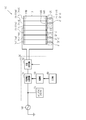
- FIG. 2 is a diagram illustrating an electrical configuration of the light control device according to the first embodiment.
- FIG. 5 is a diagram illustrating a relationship between an applied voltage, a parallel light transmittance, and a haze for a light control unit included in the light control sheet of the first embodiment.
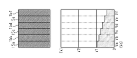
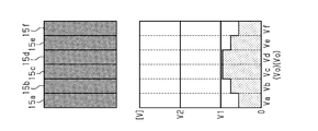
- FIG. 4 is a diagram schematically illustrating the transparency and the magnitude of an applied voltage of a plurality of light control units in the light control device of the first embodiment.
- FIG. 4 is a diagram schematically illustrating the transparency and the magnitude of an applied voltage of a plurality of light control units in the light control device of the first embodiment.
- FIG. 4 is a diagram schematically illustrating the transparency and the magnitude of an applied voltage of a plurality of light control units in the light control device of the first embodiment.
- FIG. 4 is a diagram schematically illustrating the transparency and the magnitude of an applied voltage of a plurality of light control units in the light control device of the first embodiment.
- FIG. 4 is a diagram schematically illustrating a part of a process in which the transparency of a plurality of light control units changes in the light control device of the first embodiment.
- FIG. 4 is a diagram schematically illustrating a part of a process in which the transparency of a plurality of light control units changes in the light control device of the first embodiment.
- FIG. 4 is a diagram schematically illustrating a part of a process in which the transparency of a plurality of light control units changes in the light control device of the first embodiment.
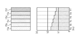
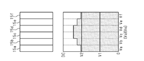
- the figure which shows typically the transparency of the some light control part in the light control device of 2nd Embodiment, and the magnitude of an applied voltage The figure which shows typically the transparency of the some light control part in the light control device of 2nd Embodiment, and the magnitude of an applied voltage.
- a first embodiment of a light control device will be described with reference to the drawings.
- the structure of the light control sheet provided in the light control device of the first embodiment will be described.
- the light control sheet is used by being attached to a transparent member.
- the surface to which the light control sheet is attached may be a flat surface or a curved surface.
- the light control sheet is attached to a building material such as a window glass, a partition or a glass wall, or a vehicle member such as an automobile window glass.
- the light control sheet 10 includes a light control layer 11, a first transparent electrode layer 12A and a second transparent electrode layer 12B as a pair of transparent electrode layers, and a first transparent electrode layer as a pair of transparent support layers. It has a transparent support layer 13A and a second transparent support layer 13B.
- the first transparent electrode layer 12A and the second transparent electrode layer 12B sandwich the light control layer 11, and the first transparent support layer 13A and the second transparent support layer 13B are connected to the light control layer 11 and the transparent electrode layers 12A and 12B. Is sandwiched between.
- the first transparent support layer 13A supports the first transparent electrode layer 12A
- the second transparent support layer 13B supports the second transparent electrode layer 12B.
- the first transparent electrode layer 12A is connected to an external circuit through a wiring extending from the first terminal portion 14A disposed on the surface of the first transparent electrode layer 12A.
- the second transparent electrode layer 12B is connected to an external circuit through a wiring extending from a second terminal portion 14B disposed on the surface of the second transparent electrode layer 12B.
- the first terminal portion 14A at the end of the light control sheet 10, the first transparent electrode layer 12A is exposed from the light control layer 11, the second transparent electrode layer 12B, and the second transparent support layer 13B.
- the second transparent electrode layer 12B is exposed from the light control layer 11, the first transparent electrode layer 12A, and the first transparent support layer 13A.
- the terminal portions 14A and 14B constitute a part of the light control sheet 10.
- the light control layer 11 includes a liquid crystal composition.
- the light modulating layer 11 is made of, for example, a polymer network type liquid crystal (PNLC: Polymer Network Liquid Crystal), a polymer dispersed type liquid crystal (PDLC: Polymer Dispersed Liquid Liquid Crystal), a capsule type nematic liquid crystal (NCAP: Nematic Liquid Crystal, etc.). Be composed.
- PNLC Polymer Network Liquid Crystal
- PDLC Polymer Dispersed Liquid Liquid Crystal
- NCAP Nematic Liquid Crystal, etc.
- a polymer network type liquid crystal includes a polymer network having a three-dimensional network, and holds liquid crystal molecules in voids of the polymer network.
- the liquid crystal molecules included in the light control layer 11 have, for example, a positive dielectric anisotropy, and the dielectric constant in the major axis direction of the liquid crystal molecules is larger than the dielectric constant in the minor axis direction of the liquid crystal molecules.
- Liquid crystal molecules include, for example, Schiff base, azo, azoxy, biphenyl, terphenyl, benzoate, tolan, pyrimidine, cyclohexanecarboxylate, phenylcyclohexane, and dioxane liquid crystal molecules. is there.
- Each of the first transparent electrode layer 12A and the second transparent electrode layer 12B is a transparent layer having conductivity.
- a material constituting the transparent electrode layers 12A and 12B for example, indium tin oxide (ITO), fluorine-doped tin oxide (FTO), tin oxide, zinc oxide, carbon nanotube (CNT), poly (3,4-ethylenedioxide) Examples include a polymer containing (oxythiophene) (PEDOT), a multilayer film including an Ag alloy thin film, and the like.
- Each of the first transparent support layer 13A and the second transparent support layer 13B is a transparent base material.
- the transparent support layers 13A and 13B for example, a glass substrate or a silicon substrate, or a high-level material made of polyethylene, polystyrene, polyethylene terephthalate, polyvinyl alcohol, polycarbonate, polyvinyl chloride, polyimide, polysulfone, cycloolefin polymer, triacetyl cellulose, or the like is used.
- a molecular film is used.
- the light control device 100 includes a light control sheet 10, a voltage distribution unit 20, a drive unit 30, and an input unit 40.
- the light control sheet 10 has a plurality of light control sections 15.
- the light control sheet 10 includes six light control sections 15 will be described as an example.
- the light control section 15 In a plan view seen from a position facing the surface of the light control sheet 10, the light control section 15 has a rectangular band shape extending along one direction.
- the plurality of light control sections 15 extend in a common direction, and are arranged in a direction orthogonal to the direction in which the light control sections 15 extend.
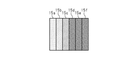
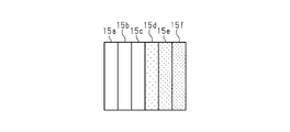
- the six light control units 15 are arranged in this order from the left as viewed in the drawing, in the order of light control unit 15a, light control unit 15b, light control unit 15c, light control unit 15d, light control unit 15e, and light control unit 15f.
- the first transparent electrode layer 12A is insulated between the light control units 15 adjacent to each other.
- the first terminal portions 14 ⁇ / b> A are separately arranged for each light control portion 15.
- the second transparent electrode layer 12B is continuous between the light control sections 15 adjacent to each other, and one second terminal section 14B common to each light control section 15 is disposed on the second transparent electrode layer 12B.
- a different voltage signal is input to the first transparent electrode layer 12A for each light control unit 15, and a voltage signal common to all the light control units 15 is input to the second transparent electrode layer 12B.
- the second transparent electrode layer 12B may be insulated between the light control sections 15 adjacent to each other. Good.
- the drive unit 30 includes a variable voltage generation circuit 31, an AC generation circuit 32, a control unit 33, and an AC / DC adapter 34.
- the variable voltage generation circuit 31 and the AC generation circuit 32 constitute a drive voltage output unit or a drive voltage output circuit.
- variable voltage generation circuit 31 An AC voltage is input from the AC power supply 50 to the variable voltage generation circuit 31.
- the variable voltage generation circuit 31 generates a DC voltage having a magnitude according to a control signal from the control unit 33 from the input AC voltage. That is, the variable voltage generation circuit 31 is configured to be able to output DC voltages of different magnitudes from each other.
- the AC generation circuit 32 generates, from the DC voltage input from the variable voltage generation circuit 31, an AC voltage having an effective value corresponding to the magnitude of the DC voltage and a frequency according to a control signal from the control unit 33. .
- the AC generation circuit 32 includes a full bridge circuit. Then, the AC generation circuit 32 generates an AC voltage having a rectangular waveform by switching according to a control signal from the control unit 33, and outputs the AC voltage as a drive voltage.
- the control unit 33 is, for example, a microcomputer that performs software processing, and controls the magnitude of the DC voltage generated by the variable voltage generation circuit 31 and the frequency of the AC voltage generated by the AC generation circuit 32.
- the control unit 33 outputs a signal based on the signal from the input unit 40 to the variable voltage generation circuit 31 as a control signal for defining the magnitude of the output voltage of the variable voltage generation circuit 31.
- the control unit 33 outputs a control signal for causing the switching to be performed to the AC generation circuit 32 so that the AC voltage having a preset frequency is generated by the AC generation circuit 32.
- the AC / DC adapter 34 generates a DC voltage having a magnitude suitable for the operation of the control unit 33 from the AC voltage input from the AC power supply, and outputs the DC voltage to the control unit 33.
- the light control device 100 includes an operation unit such as a touch sensor and a switch.
- the operation unit is configured to be able to detect an operation amount of an operation performed by the user of the light control device 100 on the operation unit. For example, if the operation unit is a touch sensor, the movement amount of the finger on the operation surface of the touch sensor is detected as the operation amount.
- the input unit 40 outputs an electric signal corresponding to the operation amount of the operation unit to the control unit 33.
- the input unit 40 includes, for example, a potentiometer. That is, the control unit 33 gradually increases or decreases the magnitude of the output voltage of the variable voltage generation circuit 31 based on the input from the input unit 40 according to the operation amount of the operation unit.
- the magnitude of the drive voltage output from the drive unit 30 changes according to the operation amount of the operation unit.
- the magnitude of the AC voltage means the magnitude of the effective value of the AC voltage.
- the voltage distribution unit 20 includes a capacitor 21 connected in series with the single dimming unit 15.
- the capacitor 21 is an example of a voltage dividing circuit.
- the capacitors 21 are separately provided for each of the light control units 15, and the voltage distribution unit 20 includes a plurality of capacitors 21 connected to different light control units 15.
- the plurality of light control units 15 are connected in parallel to the drive unit 30, and the drive voltage output by the AC generation circuit 32 of the drive unit 30 is applied to a series circuit of the light control unit 15 and the capacitor 21.
- the plurality of dimming units 15 may include the dimming unit 15 to which the capacitor 21 is not connected.
- the condenser 21 is not connected to the dimmer 15a, but the condenser 21 is connected to each of the dimmers 15b to 15f.
- a capacitor 21b is connected to the light control unit 15b
- a capacitor 21c is connected to the light control unit 15c
- a capacitor 21d is connected to the light control unit 15d
- a capacitor 21e is connected to the light control unit 15e.
- a capacitor 21f is connected to the section 15f.
- the capacitance of the five capacitors 21b to 21f is such that when a drive voltage of an arbitrary magnitude is applied to the series circuit of the light control sheet 10 and the voltage distribution unit 20, the magnitude of the voltage applied to the light control units 15a to 15f is small. , From the light control unit 15a to the light control unit 15f, the light control unit 15 is set to be smaller in the order in which the light control units 15 are arranged.
- the voltage applied to this series circuit is divided by connecting the capacitor 21 in series to the dimming unit 15. Since the light control unit 15 is equivalent to an RC parallel circuit equivalently, the voltage applied to the light control unit 15 decreases as the capacitance of the capacitor 21 connected to the light control unit 15 decreases. For example, when the capacities of the dimmers 15b to 15f are constant, specifically, when the areas of the dimmers 15b to 15f in a plan view are constant, the capacitance of the capacitor 21 is equal to the capacitance of the capacitors 21b and 21c. , Capacitor 21d, capacitor 21e, and capacitor 21f in this order.
- the direction of the major axis direction of the liquid crystal molecules is irregular. Therefore, the light incident on the light control layer 11 is scattered, and the light control unit 15 appears cloudy.
- the liquid crystal molecules are aligned according to the magnitude of the applied voltage, and the major axis direction of the aligned liquid crystal molecules is The direction is along the direction of the electric field between the transparent electrode layers 12A and 12B. As a result, light is easily transmitted through the light control layer 11, and the transparency of the light control unit 15 increases as the applied voltage increases.
- the transparency of the light control unit 15 in the present embodiment is an index quantified as haze and parallel light transmittance. The higher the transparency, the smaller the haze and the higher the parallel light transmittance. The lower the transparency, the higher the haze and the lower the parallel light transmittance.
- the haze and the parallel light transmittance hardly change even if the applied voltage changes, up to the first threshold voltage V1.
- the change rate of the haze and the parallel light transmittance with respect to the applied voltage that is, the change amount of the haze and the parallel light transmittance per unit change of the applied voltage is small. Therefore, when the applied voltage is lower than the first threshold voltage V1, the transparency of the light control unit 15 is the lowest, and the light control unit 15 is opaque.
- the haze and the parallel light transmittance greatly change according to the change in the applied voltage.
- the change rate of the haze and the parallel light transmittance with respect to the applied voltage is large.
- the transparency of the light control section 15 changes greatly according to the change in the applied voltage.
- the haze and the parallel light transmittance hardly change even if the applied voltage changes. In other words, the change rate of the haze and the parallel light transmittance with respect to the applied voltage is small.
- the transparency of the light control unit 15 is the highest.
- the first threshold voltage V1 and the second threshold voltage V2 differ depending on the type of liquid crystal used for the light control layer 11, in the example shown in FIG. 3, the first threshold voltage V1 is 10V, and the second threshold voltage is V2 is 20V.
- the light control sheet 10 has an opaque mode in which all of the light control sections 15 are opaque and there is no visible difference in transparency, and a gradation mode in which there is a visible difference in transparency among the plurality of light control sections 15. And a transparent mode in which all of the light control sections 15 are transparent and there is no visible difference in transparency.
- Each mode will be described with reference to FIGS. 4 to 6, the transparency of each light control unit 15 is represented by a dot density, and the magnitude of the voltage applied to each light control unit 15 is shown by a bar graph.
- a voltage having a magnitude equal to or less than Vo is applied to the light control units 15a to 15f. Then, as described above, the applied voltage Va of the light control unit 15a, the applied voltage Vb of the light control unit 15b, the applied voltage Vc of the light control unit 15c, the applied voltage Vd of the light control unit 15d, and the applied voltage of the light control unit 15e Ve and the applied voltage Vf of the light control section 15f decrease in this order.
- the maximum value of the applied voltage of the light control units 15a to 15f that is, the magnitude of the applied voltage Va of the light control unit 15a is controlled by the drive. It is equal to the magnitude of the voltage Vo.
- the applied voltages Va to Vf of the light control units 15a to 15f are all equal to the first threshold voltage. Less than V1.
- the voltage difference Vdf which is the difference between the maximum value and the minimum value of the applied voltages of the light control units 15a to 15f, is smaller than the first threshold voltage V1. (0 ⁇ Vdf ⁇ V1).
- the voltage difference Vdf is the difference between the applied voltage Va of the light control unit 15a and the applied voltage Vf of the light control unit 15f.
- the light control units 15a to 15f are set so that all of the applied voltages Va to Vf are equal to or higher than the first threshold voltage V1 and equal to or lower than the second threshold voltage V2.
- the voltage difference Vdf in the dimmers 15a to 15f is equal to or less than the difference between the second threshold voltage V2 and the first threshold voltage V1 (0 ⁇ Vdf ⁇ V2-V1).
- the applied voltage Va is the second threshold voltage V2
- each of the applied voltages Va to Vf of the dimmers 15a to 15f is equal to or higher than the first threshold voltage V1 and equal to or lower than the second threshold voltage V2.
- the haze and the parallel light transmittance of the light control unit 15 are changed according to the magnitude of the applied voltage. change.
- the applied voltage Va is equal to or higher than the predetermined value within the range of not less than the first threshold voltage V1 and not more than the second threshold voltage V2
- the applied voltages Va to Vf of the dimming units 15a to 15f are equal to or more than the first threshold voltage V1.
- the magnitudes are different from each other within a range equal to or lower than the threshold voltage V2, and gradually decrease from the applied voltage Va toward the applied voltage Vf.
- the transparency of the light control units 15a to 15f is different from each other, and the transparency gradually decreases from the light control unit 15a toward the light control unit 15f. That is, the user recognizes the difference in the transparency of the light control units 15a to 15f, and the light control sheet 10 enters the gradation mode.
- the gradation mode includes a state in which the transparency of some of the light control units 15a to 15f is different from the other, and a state in which the transparency of each of the light control units 15a to 15f is different from each other as described with reference to FIG. including.
- the transparency changes according to the magnitude of the applied voltage. Even if the applied voltages Va to Vf of the dimming units 15a to 15f change with the change of the drive voltage from the drive unit 30, the magnitude relationship between the applied voltages Va to Vf does not change, and the applied voltage Va to the applied voltage Vf Toward, the voltage decreases.
- the direction of the gradient of the transparency in the light control units 15a to 15f is constant, and the transparency of the light control unit 15 on the left side of the paper surface from the light control unit 15a to the light control unit 15f is constant. As described below, the transparency of the light control unit 15 decreases.
- the drive mode from the drive unit 30 gradually increases and the drive mode transitions from the opaque mode to the transparent mode via the gradation mode.
- the transparency of all of the light control units 15a to 15f is the lowest.
- the applied voltages Va to Vf increase with an increase in the driving voltage
- the transparency increases in order from the dimming unit 15a when the applied voltage becomes equal to or higher than the first threshold voltage V1.
- the dimming units 15d and 15e are equal to or higher than the first threshold voltage V1 and the applied voltages Vd, Ve, and Vf are lower than the first threshold voltage V1, as shown in FIG. 7A, the dimming units 15d and 15e.
- the light control units 15a, 15b, and 15c are opaque as in the opaque mode.
- the transparency of the light control units 15a, 15b, and 15c is higher than that in the opaque mode, and the transparency decreases in the order of the light control units 15a, 15b, and 15c.
- the transparency becomes highest in the light control section 15 in which the applied voltage exceeds the second threshold voltage V2.
- the applied voltages Va, Vb, and Vc are higher than the second threshold voltage V2 and the applied voltages Vd, Ve, and Vf are equal to or higher than the first threshold voltage V1 and equal to or lower than the second threshold voltage V2, as illustrated in FIG.
- the dimmers 15a, 15b, 15c are transparent and have the same transparency as in the transparent mode.
- the transparency of the light control units 15d, 15e, and 15f is lower than that in the transparent mode, and the transparency decreases in the order of the light control units 15d, 15e, and 15f.
- the transparency of all of the dimming units 15a to 15f becomes the highest, and the mode is the transparent mode.
- the drive voltage from the drive unit 30 gradually decreases, the drive mode transitions from the transparent mode to the opaque mode via the gradation mode, and the transparency of each light control unit 15 gradually decreases.
- the light control unit 15 changes the opaque mode to the transparent mode via the gradation mode or the transparent mode to the opaque mode via the gradation mode by gradually increasing or decreasing the drive voltage. Is continuously changing. Further, even in the gradation mode, the transparency of each light control section 15 changes continuously. In other words, between a state in which all the light control units 15 are opaque and a state in which all the light control units 15 are transparent, a state in which a difference in transparency occurs between the plurality of light control units 15, The transparency of each light control section 15 changes continuously. In particular, during the transition of the transparency in the gradation mode, a portion having a high transparency or a portion having a low transparency in the light control sheet 10 appears to move continuously in the plane of the light control sheet 10. .
- the timing and speed of the transition of the drive mode between the opaque mode, the gradation mode, and the transparent mode, and the transition of the transparency of the light control units 15a to 15f in the gradation mode are determined by the drive voltage output by the drive unit 30. Is controlled by the timing and speed of the change in the magnitude of the drive voltage, and such a change in the drive voltage is controlled by the control unit 33.
- the control unit 33 controls a change in the drive voltage in accordance with a user's operation amount on the operation unit based on a signal from the input unit 40. For example, when the operation unit is a touch sensor, the control unit 33 controls a change in the drive voltage according to the moving direction and the moving amount of the finger on the operation surface of the touch sensor. Thereby, the drive mode of the light control sheet 10 changes according to the operation amount.
- a common drive voltage is output from the drive unit 30 to the plurality of light control units 15, and the voltage distribution unit 20 forms a difference between the applied voltages of the plurality of light control units 15. That is, the fact that the capacitors 21 are connected in series with some of the dimming units 15 and that the capacities of the plurality of capacitors 21 are different from each other causes the applied voltage between the plurality of dimming units 15 to be stepwise. Change. Therefore, as compared with the case where a circuit for generating a power supply and a drive voltage is separately provided for each light control unit 15, gradation expression can be performed with a simple circuit configuration. Therefore, an increase in the size of the accommodation portion of the circuit in the light control device 100 is also suppressed.
- the dimming unit 15 has a small rate of change in light transmittance and haze with respect to the applied voltage. It has a characteristic that the above-mentioned rate of change is large in a voltage range of two threshold voltages V2 or less.
- the applied voltage of each dimming unit 15 is made different by the connection of the capacitor 21, there is always a difference in the applied voltage among the plurality of dimming units 15.
- the difference in the applied voltage between the plurality of light control units 15 is reduced. Even if there is no change, it is possible to increase or decrease the difference in transparency between the plurality of light control units 15.
- a state in which all the applied voltages of the respective light control units 15 may be included in a range of the first threshold voltage V1 or more and the second threshold voltage V2 or less, which is a voltage region where the rate of change is large, is as follows.
- the capacity of each capacitor 21 is set.
- the difference in transparency among the plurality of light control units 15 can be increased.
- the user can easily recognize the gradient of the transparency in the light control sheet 10. That is, the user can easily recognize the gradation mode.
- the transparency of the plurality of light control units 15 can be made different from each other according to the difference in the applied voltage, an expression having the number of gradations corresponding to the number of the light control units 15 is possible.
- the characteristics of the above-mentioned change rate in the light control section 15 it is possible to realize three types of driving modes: an opaque mode, a gradation mode, and a transparent mode. Therefore, various expressions on the light control sheet 10 are possible. It should be noted that such characteristics of the light control section 15 are preferably realized by using liquid crystal as the material of the light control layer 11.
- the voltage applied to the light control unit 15 decreases from the light control unit 15a located at one end in the direction in which the plurality of light control units 15 are arranged to the light control unit 15f located at the other end.
- the capacity of the capacitor 21 is set. Therefore, as the gradation mode, an expression in which the transparency of the light control unit 15 changes from the light control unit 15a at one end to the light control unit 15f at the other end in accordance with the order of arrangement of the light control units 15 is possible. . Therefore, by the transition of the drive mode between the opaque mode, the gradation mode, and the transparent mode, a natural expression in which the transparency in the light control sheet 10 changes like a one-sided curtain over time is possible. Thus, the design of the light control sheet 10 is enhanced.
- the drive voltage common to the respective light control units 15 is divided by the capacitor 21, so that a difference is generated in the applied voltage among the plurality of light control units 15. Therefore, gradation expression can be performed with a simple circuit configuration.
- the plurality of capacitors 21 connected to the different light control units 15 include capacitors 21 having different capacities. According to this, the plurality of dimming units 15 are determined by the difference in capacitance between the plurality of capacitors 21, in other words, the difference in the voltage division ratio between the capacitor and the dimming unit in the plurality of sets of the capacitors and the dimming unit. Between the applied voltages can be controlled. Therefore, the difference between the applied voltages among the plurality of light control units 15 can be accurately controlled with a simple configuration.
- the change rates of the light transmittance and the haze with respect to the applied voltage are relative when the applied voltage is lower than the first threshold voltage V1 and when the applied voltage exceeds the second threshold voltage V2.
- the applied voltage is higher than or equal to the first threshold voltage and lower than or equal to the second threshold voltage. Therefore, by using a voltage region having a different change rate as the voltage region including the applied voltage of each light control unit 15, in a state where there is a difference in the applied voltage between the plurality of light control units 15, The difference in transparency between the plurality of light control sections 15 can be increased or decreased.
- the light control layer 11 includes the liquid crystal composition
- the light control unit 15 whose light transmittance changes in accordance with the magnitude of the applied voltage is suitably realized. Is preferably realized.
- the voltage difference Vdf is greater than 0 and less than the first threshold voltage V1, and the maximum value of the applied voltage is equal to the first threshold voltage V1.
- the difference is equal to or more than a predetermined value in a range from the first threshold voltage V1 to the second threshold voltage V2
- the voltage difference Vdf is equal to or less than the difference between the first threshold voltage V1 and the second threshold voltage V2. According to this, there may be a state where all of the voltages applied to the plurality of light control units 15 are included in the voltage region where the change rate is large.
- the voltage distribution unit 20 is configured such that the magnitude of the applied voltage changes between the plurality of light control units 15 according to the order of arrangement of the plurality of light control units 15,
- the gradation expression in which the transparency of the light control section 15 gradually changes in accordance with the order of is possible. Therefore, a gradation-like expression is possible.
- the voltage applied to the light control unit 15 decreases from the light control unit 15a located at one end in the direction in which the plurality of light control units 15 are arranged to the light control unit 15f located at the other end.
- the voltage distribution unit 20 is configured. According to this, a gradation-like expression in which the transparency changes from one end to the other end in the direction in which the plurality of light control units 15 are arranged can be achieved. Therefore, a natural expression such as a one-sided curtain is possible, and the design of the light control sheet 10 is enhanced.
- the plurality of dimmers 15 are mutually connected between the first state in which all dimmers 15 are opaque and the second state in which all dimmers 15 are transparent.
- the transparency of each of the plurality of light control units 15 continuously changes between the first state and the second state so as to include the third state including the light control units 15 having different transparency. According to this, the transparency of the light control sheet 10 can be dynamically expressed by the change in the transparency of each light control section 15, and the design of the light control sheet 10 is enhanced.
- the dimming device 110 has a configuration related to the connection between the plurality of capacitors 21 included in the voltage distribution unit 20 and the dimming sheet 10, and the magnitude relationship between the capacitances of the plurality of capacitors 21.
- this is different from the first embodiment.
- the configurations of the light control sheet 10, the drive unit 30, and the input unit 40 are the same as those of the first embodiment.
- the capacitors 21 included in the voltage distribution unit 20 are separately provided for each of the light control units 15, and the plurality of capacitors 21 are connected to different light control units 15.
- the capacitors 21 are not connected to the light control units 15c and 15d, but the capacitors 21 are connected to the light control units 15a, 15b, 15e, and 15f.
- the condenser 21a is connected to the dimmer 15a
- the condenser 21b is connected to the dimmer 15b
- the condenser 21e is connected to the dimmer 15e
- the condenser 21f is connected to the dimmer 15f.
- the capacities of the four capacitors 21a, 21b, 21e, and 21f are equal to the voltages applied to the light control units 15a to 15f when a drive voltage of an arbitrary magnitude is applied to the series circuit of the light control sheet 10 and the voltage distribution unit 20. Is set to decrease from the central light control section 15 in the direction in which the light control sections 15 are arranged to each of the light control sections 15 at both ends.
- the voltage applied to the light control unit 15 decreases from the light control unit 15c located at the center to the light control unit 15a located at one end in the arrangement of the light control units 15, and
- the capacitance of the capacitor 21 is set so that the voltage applied to the dimming unit 15 decreases from the dimming unit 15d located at the center to the dimming unit 15f located at the other end in the row of 15. I have.
- the capacity of the capacitor 21a is smaller than the capacity of the capacitor 21b
- the capacity of the capacitor 21f is smaller than the capacity of the capacitor 21e.
- the capacitors 21b and 21e have the same capacitance, and the capacitors 21a and 21f have the same capacitance.
- a voltage of an undivided magnitude is applied. That is, among the light control units 15b to 15f, the applied voltage of the light control units 15c and 15d is the largest, and the applied voltage decreases from the light control unit 15c toward the light control unit 15a. The applied voltage decreases toward the light control section 15f.
- the applied voltages of the light control sections 15c and 15d are equal to each other, the applied voltages of the light control sections 15b and 15e are equal to each other, and the applied voltages of the light control sections 15a and 15f are equal to each other.
- the light control sheet 10 has an opaque mode in which all of the light control sections 15 are opaque and there is no visible difference in transparency, and a difference in visibility between the plurality of light control sections 15 in transparency. , And a transparent mode in which all of the light control sections 15 are transparent and there is no visible difference in transparency. Each mode will be described with reference to FIGS.
- the maximum value of the applied voltage of the light control units 15a to 15f that is, the applied voltages Vc and Vd of the light control units 15c and 15d. Is equal to the magnitude of the driving voltage Vo.
- the applied voltages Va to Vf of the light control units 15a to 15f are all equal to the first voltage. It becomes lower than the threshold voltage V1.
- the voltage difference Vdf which is the difference between the maximum value and the minimum value of the applied voltages of the dimming units 15a to 15f, is larger than the first threshold voltage V1. Is also small (0 ⁇ Vdf ⁇ V1).
- the voltage difference Vdf is the difference between the applied voltages Vc and Vd of the dimmers 15c and 15d and the applied voltages Va and Vf of the dimmers 15a and 15f.
- the voltage difference Vdf in the dimmers 15a to 15f is equal to or less than the difference between the second threshold voltage V2 and the first threshold voltage V1 (0 ⁇ Vdf ⁇ V2 -V1).
- the transparency gradually decreases from the light control unit 15c toward the light control unit 15a, and the transparency gradually decreases from the light control unit 15d toward the light control unit 15f. That is, the user recognizes the difference in the transparency of the light control units 15a to 15f, and the light control sheet 10 enters the gradation mode.
- the transparent mode will be described with reference to FIG.
- the minimum applied voltages Va and Vf to the light control units 15a to 15f exceed the second threshold voltage V2
- the applied voltages Va to Vf of the light control units 15a to 15f are all higher than the second threshold voltage V2.
- the light control units 15a to 15f are all transparent, and the difference in transparency among the light control units 15a to 15f is not recognized by the user.
- the applied voltages Va and Vf are higher than the second threshold voltage V2
- the light control sheet 10 is in the transparent mode.
- the magnitude relationship between the applied voltages Va to Vf does not change.
- the voltages decrease from the voltages Vc and Vd toward the applied voltages Va and Vf. Therefore, in the gradation mode, the direction of the gradient of the transparency in the light control sections 15a to 15f is constant, and the light control sections 15c and 15d at the center are directed toward the light control sections 15a and 15f at the end. 15 is less transparent.
- the transparency of the dimming unit 15c is equal to that of the dimming unit 15d. That is, the transparency of the light control unit 15b and the light control unit 15e become equal, and the transparency of the light control unit 15a and the light control unit 15f become equal.
- the transparency of the central light control units 15c and 15d is changed. Then, the transparency of the light control units 15b and 15e starts to increase, and finally, the transparency of the light control units 15a and 15f at the ends starts to increase.
- the transparency of all of the light control sections 15a to 15f is maximized, the entire light control sheet 10 becomes transparent.
- the dimming device 110 of the second embodiment by gradually increasing or decreasing the driving voltage, all the dimming units 15 are in a transparent state and all the dimming units 15 are in an opaque state.
- the transparency of each light control unit 15 continuously changes while passing through a state in which the transparency between the plurality of light control units 15 is different.
- the capacitors 21 are connected in series with some of the light control units 15 and the capacities of the plurality of capacitors 21 are different. As a result, a difference is generated in the applied voltage among the plurality of light control units 15. Therefore, as compared with a configuration in which a circuit for generating a power supply and a drive voltage is separately provided for each light control unit 15, gradation can be expressed with a simple circuit configuration. Further, by utilizing the characteristics of the light transmittance and the change rate of the haze in the light control section 15, it is possible to realize three types of driving modes: an opaque mode, a gradation mode, and a transparent mode.
- the applied voltage decreases from the dimming units 15c and 15d located at the center in the direction in which the plurality of dimming units 15 are arranged to each of the dimming units 15a and 15f located at both ends.
- the capacitance of the capacitor 21 is set. Therefore, in the gradation mode, the expression in which the transparency of the light control unit 15 changes from the center light control units 15c and 15d to each of the light control units 15a and 15f at both ends in accordance with the order of the light control units 15 is provided. Is possible. Therefore, by the transition of the driving mode between the opaque mode, the gradation mode, and the transparent mode, a characteristic expression in which the transparency changes like a double curtain with the passage of time can be achieved. Design is enhanced.
- the following effects can be obtained in addition to the effects (1) to (5) and (7) of the first embodiment.
- the applied voltage of the light control unit 15 decreases from the light control units 15c and 15d located at the center in the direction in which the plurality of light control units 15 are arranged to each of the light control units 15a and 15f located at both ends.
- the voltage distribution unit 20 is configured. According to this, a gradation-like expression in which the transparency changes from the central portion in the direction in which the plurality of light control portions 15 are arranged to each of the both end portions is possible. Therefore, a characteristic expression such as a double curtain is possible, and the design of the light control sheet 10 is enhanced.
- the capacities of the plurality of light control units 15 need not be constant. For example, the area of the plurality of light control units 15 in plan view may not be constant.
- the magnitude relationship between the capacitances of the plurality of capacitors 21 does not always match the magnitude relationship between the applied voltages of the plurality of light control units 15.
- the capacitance of the dimmers 15 to which the capacitors 21 of the plurality of dimmers 15 are connected and the capacitance of the capacitors 21 connected to the respective dimmers 15 are smaller than desired by the applied voltage in the plurality of dimmers 15. What is necessary is just to determine so that a relationship may be formed. Further, a capacitor 21 for each light control unit 15 may be connected to every light control unit 15.
- the number of light control portions 15 included in the light control sheet 10 may be two or more, and is not limited. Further, the shape of the light control unit 15 in plan view is not limited to a rectangular band shape, and the plurality of light control units 15 may not be arranged in one direction. For example, the light control sheet 10 includes a plurality of light control units 15 having a square shape in plan view, and the plurality of light control units 15 may be arranged in a matrix.
- the magnitude relationship between the applied voltages in the plurality of light control units 15 is not limited to the relationship in which the magnitude of the applied voltage changes in accordance with the order of arrangement of the plurality of light control units 15.
- an element for dividing the drive voltage such as the capacitor 21
- the gradation mode is set. Mosaic expression is possible.
- the control unit 33 only has to gradually increase or decrease the drive voltage output from the drive unit 30 based on the operation on the operation unit. It does not need to be reflected in the transition between the key mode and the transparent mode.
- the operation unit does not have to be configured to be able to detect the operation amount.
- the operation unit may be a switch that instructs switching between an opaque mode, a gradation mode, and a transparent mode, and may be configured to detect only the presence or absence of an operation.
- the control unit 33 is not limited to performing software processing for all processing executed by itself.
- the control unit 33 may include a dedicated hardware circuit (for example, an application-specific integrated circuit: ASIC) that performs hardware processing for at least a part of the processing executed by the control unit 33.
- ASIC application-specific integrated circuit
- the control unit 33 includes 1) one or more processors that operate according to a computer program (software), 2) one or more dedicated hardware circuits that execute at least a part of various processes, or 3). It can be configured as a processing circuit including a combination thereof.
- the processor includes a CPU and memories such as a RAM and a ROM, and the memory stores program codes or instructions configured to cause the CPU to execute processing.
- Memory or computer readable media includes any available media that can be accessed by a general purpose or special purpose computer.
- the voltage dividing circuit is connected not only to the capacitor 21 but also to one of the plurality of dimming units 15 to divide the driving voltage, and to change the magnitude of the applied voltage of the connected dimming unit 15 to another. Any circuit may be used as long as it is different from the magnitude of the voltage applied to at least one light control section 15.
- the drive unit 30 generates the drive voltage from the AC voltage input from the AC power supply 50.
- the drive unit 30 is not limited thereto, and may generate a drive voltage that is an AC voltage from a DC voltage input from a DC power supply.
- the drive unit 30 may be configured to be able to output AC voltages having different effective values as drive voltages. Then, the magnitude of the driving voltage may be controlled by the control unit 33.
- the light control sheet 10 may include another layer in addition to the light control layer 11, the transparent electrode layers 12A and 12B, and the transparent support layers 13A and 13B.
- the other layers include, for example, a layer for protecting the light control layer 11 and the transparent electrode layers 12A and 12B, such as a layer having an ultraviolet barrier function, and characteristics such as strength and heat resistance of the light control sheet 10. And the like.
- the light control sheet 10 may include a pair of alignment layers that sandwich the light control layer 11 between the light control layer 11 and the transparent electrode layers 12A and 12B.
- the alignment layer is a layer that controls the alignment of the liquid crystal molecules included in the light control layer 11, and aligns the liquid crystal molecules in the normal direction of the transparent electrode layers 12A and 12B when no driving voltage is applied. In the configuration including the alignment layer, the transparency of the light control unit 15 decreases as the voltage applied to the light control unit 15 increases.
- the light control layer 11 may include a dye having a predetermined color and not hindering the movement of the liquid crystal molecules according to the magnitude of the voltage applied to the light control layer 11. According to such a configuration, the light control sheet 10 having a predetermined color is realized.
- the light control layer 11 may be made of a material different from the liquid crystal as long as the light control unit 15 whose light transmittance changes in accordance with the magnitude of the applied voltage can be realized. (Example)
- the light control device described above will be described using a specific example.
- the light control device of the first embodiment is a light control device corresponding to the first embodiment.
- [Configuration of light control sheet] Using a polymer network type liquid crystal for the light control layer 11, a light control sheet 10 having six light control portions 15a to 15f was formed. The relationship between the applied voltage, the haze, and the parallel light transmittance in the light control sheet 10 has the characteristics shown in FIG.
- the first threshold voltage V1 is 10V
- the second threshold voltage V2 is 20V.
- Each of the dimmers 15a to 15f has a rectangular band shape in plan view, and the six dimmers 15a to 15f are arranged in one direction. That is, the light control units 15a to 15f are arranged in the arrangement shown in FIG.
- the widths of the light control units 15a to 15f are not constant, that is, the areas of the light control units 15a to 15f in plan view are not constant.
- the sizes of the light control units 15a to 15f in plan view are as follows. As described below, the areas of the light control sections 15a and 15f at both ends are larger than the areas of the light control sections 15b, 15c, 15d and 15e.
- -Light control part 15a 58 mm x 255 mm -Light control part 15b: 47 mm x 255 mm -Light control part 15c: 47 mm x 255 mm -Light control part 15d: 47 mm x 255 mm -Light control part 15e: 47 mm x 255 mm -Light control part 15f: 58 mm x 255 mm [Change in applied voltage]
- the condenser 21 was not connected to the light controller 15a, but capacitors 21 having different capacities were connected to the light controllers 15b to 15f, respectively, to constitute the light controller 100.
- the drive voltage Vo is a rectangular wave AC voltage having a frequency of 50 Hz.
- Table 1 shows the capacitance of the capacitor 21 connected to the light control units 15a to 15f, the magnitude of the drive voltage Vo, and the magnitude of the voltage applied to the light control units 15a to 15f.
- the voltage applied to the light control units 15a to 15f decreases from the light control unit 15a toward the light control unit 15f regardless of the magnitude of the drive voltage Vo.
- the drive voltage Vo is 10.1 V
- the maximum value of the applied voltage of the light control units 15a to 15f is 10.1V
- the minimum value is 5.1V. Therefore, when the drive voltage Vo is less than 10 V, it is suggested that there is a state where all of the applied voltages of the light control units 15a to 15f are less than the first threshold voltage V1.
- the light control device 100 of the first embodiment it is possible to realize three types of drive modes, that is, the opaque mode, the gradation mode, and the transparent mode.
- the expression in which the transparency changes in accordance with the order of arrangement of the light control units 15 from the light control unit 15a at one end to the light control unit 15f at the other end is possible.
- the dimmer according to the second embodiment is a dimmer corresponding to the second embodiment.
- the configuration of the light control sheet 10 in the second embodiment that is, the layer configuration of the light control sheet 10 and the arrangement and size of the light control section 15 are the same as those in the first embodiment.
- the dimmers 110 were constructed by connecting the capacitors 21 to the dimmers 15a, 15b, 15e, and 15f without connecting the condenser 21 to the dimmers 15c and 15d. Then, the magnitude of the voltage applied to each of the dimming units 15a to 15f was measured by changing the magnitude of the driving voltage Vo applied to the series circuit of the dimming unit 15 and the capacitor 21.
- the drive voltage Vo is a rectangular wave AC voltage having a frequency of 50 Hz.
- Table 2 shows the capacitance of the capacitor 21 connected to the light control units 15a to 15f, the magnitude of the drive voltage Vo, and the magnitude of the voltage applied to the light control units 15a to 15f.
- the voltage applied to the light control units 15a to 15f decreases from the light control unit 15c toward the light control unit 15a regardless of the magnitude of the drive voltage Vo, and also decreases from the light control unit 15d. It becomes smaller toward the light part 15f.
- the driving voltage Vo is 10.1 V
- the maximum value of the applied voltage of the light control units 15a to 15f is 10.1V
- the minimum value is 5.1V. Therefore, when the drive voltage Vo is less than 10 V, it is suggested that there is a state where all of the applied voltages of the light control units 15a to 15f are less than the first threshold voltage V1.
- the light control device 110 of the second embodiment it is possible to realize three types of drive modes, that is, the opaque mode, the gradation mode, and the transparent mode.
- the expression in which the transparency changes in accordance with the order of arrangement of the light control units 15 from the light control units 15c and 15d at the center in the direction to the light control units 15a and 15f at both ends in the direction is possible.
Landscapes
- Physics & Mathematics (AREA)
- Nonlinear Science (AREA)
- General Physics & Mathematics (AREA)
- Chemical & Material Sciences (AREA)
- Engineering & Computer Science (AREA)
- Crystallography & Structural Chemistry (AREA)
- Optics & Photonics (AREA)
- Mathematical Physics (AREA)
- Structural Engineering (AREA)
- Architecture (AREA)
- Civil Engineering (AREA)
- Liquid Crystal (AREA)
- Computer Hardware Design (AREA)
- Theoretical Computer Science (AREA)
- Dispersion Chemistry (AREA)
- Liquid Crystal Display Device Control (AREA)
- Control Of Indicators Other Than Cathode Ray Tubes (AREA)
Abstract
This light adjusting device is provided with a drive voltage output unit configured to output a drive voltage, a control unit configured to cause the drive voltage output unit to gradually increase or gradually decrease the magnitude of the drive voltage, and a plurality of light adjusting units connected in parallel to the drive voltage output unit. The light transmittance of the light adjusting units changes in accordance with the magnitude of the voltage applied to the light adjusting unit. The light adjusting device is additionally provided with a voltage-dividing circuit which is connected to one of the plurality of light adjusting units, and which is configured to divide the drive voltage, which is common to each light adjusting unit, and to make the magnitude of the voltage applied to the light adjusting unit connected to the voltage-dividing circuit differ from the magnitude of the voltage applied to at least one other light adjusting unit.
Description
本発明は、光透過率の可変な調光シートを備える調光装置に関する。
The present invention relates to a light control device provided with a light control sheet having a variable light transmittance.
調光シートは、調光層と、調光層を挟む一対の透明電極層とを備えている。一対の透明電極層間の電位差に応じて、例えば調光層が含む液晶分子の配向状態が変わることにより、調光シートの光透過率が変わる。
The light control sheet includes a light control layer and a pair of transparent electrode layers sandwiching the light control layer. The light transmittance of the light control sheet changes, for example, by changing the alignment state of the liquid crystal molecules included in the light control layer according to the potential difference between the pair of transparent electrode layers.
近年、複数の調光部を有する調光シートを備え、調光部ごとに光透過率が異なるように各調光部の光透過率を制御する調光装置が提案されている。例えば、特許文献1に記載の調光シートは、1つの方向に沿って並ぶ複数の帯状の調光部を有し、調光装置は、調光部が並ぶ方向に沿って複数の調光部の光透過率が徐々に小さくなるように、各調光部の光透過率を制御する。こうした制御によれば、調光シートの面内において透明度に勾配が形成された表現である階調表現が可能である。
In recent years, there has been proposed a light control device including a light control sheet having a plurality of light control units and controlling the light transmittance of each light control unit such that the light transmittance differs for each light control unit. For example, the light control sheet described in Patent Literature 1 has a plurality of belt-like light control units arranged in one direction, and the light control device includes a plurality of light control units along the direction in which the light control units are arranged. The light transmittance of each light control unit is controlled so that the light transmittance of the light control unit gradually decreases. According to such control, it is possible to perform gradation expression, which is an expression in which a gradient is formed in the transparency in the plane of the light control sheet.
調光シートの上記階調表現の実現のためには、透明電極層間の電位差が複数の調光部間において段階的に変化するように、各調光部に印加する電圧の大きさを制御する必要がある。そのため、上記特許文献1の調光装置は、調光部ごとに別々の電源を有しており、各調光部には、互いに異なる電源から、互いに異なる大きさの交流電圧が印加される。
In order to realize the above gradation expression of the light control sheet, the magnitude of the voltage applied to each light control section is controlled so that the potential difference between the transparent electrode layers changes stepwise between the plurality of light control sections. There is a need. Therefore, the light control device of Patent Document 1 has a separate power supply for each light control unit, and AC voltages of different magnitudes are applied to each light control unit from different power supplies.
しかしながら、調光部ごとに電源を設けることは、すなわち、調光部の駆動に適合した交流電圧を生成する回路を調光部ごとに設けることを意味する。そのため、調光部ごとの回路ユニットの構成が複雑になるとともに回路ユニットが大きくなる。さらに、回路ユニットが調光部ごとに別々に設けられる場合、複数の回路ユニットを統括して制御するための制御回路も必要となる。したがって、調光装置の回路構成が複雑になり、また、調光装置における回路の収容部分が大型にならざるを得ない。
However, providing a power supply for each light control unit means providing a circuit for generating an AC voltage suitable for driving the light control unit for each light control unit. Therefore, the configuration of the circuit unit for each light control unit becomes complicated and the circuit unit becomes large. Furthermore, when a circuit unit is provided separately for each light control unit, a control circuit for controlling a plurality of circuit units in a centralized manner is also required. Therefore, the circuit configuration of the light control device becomes complicated, and the circuit accommodating portion of the light control device must be large.
本発明は、簡素な回路構成で階調表現を可能とした調光装置を提供することを目的とする。
The present invention has an object to provide a light control device capable of expressing gradation with a simple circuit configuration.
上記課題を解決する調光装置は、駆動電圧を出力するように構成された駆動電圧出力部と、前記駆動電圧出力部に前記駆動電圧の大きさを漸増または漸減させるように構成された制御部と、前記駆動電圧出力部に対して並列に接続された複数の調光部であって、前記調光部の光透過率は、前記調光部の印加電圧の大きさに応じて変わる、前記複数の調光部を有する調光シートとを備える。さらに、上記調光装置は、前記複数の調光部のうちの1つと接続された分圧回路であって、各調光部に共通する前記駆動電圧を分圧して当該分圧回路に接続された前記調光部の印加電圧の大きさを他の少なくとも1つの前記調光部の印加電圧の大きさと異ならせるように構成された前記分圧回路を備える。
A dimming device that solves the above problem includes a driving voltage output unit configured to output a driving voltage, and a control unit configured to cause the driving voltage output unit to gradually increase or decrease the magnitude of the driving voltage. And a plurality of light control units connected in parallel to the drive voltage output unit, wherein the light transmittance of the light control unit changes according to the magnitude of the applied voltage of the light control unit, A light control sheet having a plurality of light control sections. Further, the dimming device is a voltage dividing circuit connected to one of the plurality of dimming units, and divides the driving voltage common to each dimming unit and is connected to the voltage dividing circuit. And a voltage dividing circuit configured to make the magnitude of the applied voltage of the dimming unit different from the magnitude of the applied voltage of at least one other dimming unit.
上記構成によれば、駆動電圧出力部から複数の調光部に向けて共通の駆動電圧が出力され、分圧回路によって、複数の調光部に対する印加電圧に差が形成される。したがって、駆動電圧を生成する回路が調光部ごとに別々に設けられる構成と比較して、簡素な回路構成で階調表現が可能である。
According to the above configuration, a common drive voltage is output from the drive voltage output unit to the plurality of dimming units, and a difference is formed between the voltages applied to the plurality of dimming units by the voltage dividing circuit. Therefore, as compared with a configuration in which a circuit for generating a drive voltage is separately provided for each light control unit, gradation expression can be achieved with a simple circuit configuration.
本発明によれば、調光装置において、簡素な回路構成で階調表現を可能とすることができる。
According to the present invention, in a light control device, gradation expression can be performed with a simple circuit configuration.
(第1実施形態)
図面を参照して、調光装置の第1実施形態を説明する。
[調光シートの構成]
第1実施形態の調光装置が備える調光シートの構造を説明する。調光シートは、透明な部材に貼り付けられて使用される。調光シートが貼り付けられる面は、平面であってもよいし、曲面であってもよい。例えば、調光シートは、窓ガラスやパーテーションやガラス壁等の建材、あるいは、自動車の窓ガラス等の車両用部材に取り付けられる。 (1st Embodiment)
A first embodiment of a light control device will be described with reference to the drawings.
[Configuration of light control sheet]
The structure of the light control sheet provided in the light control device of the first embodiment will be described. The light control sheet is used by being attached to a transparent member. The surface to which the light control sheet is attached may be a flat surface or a curved surface. For example, the light control sheet is attached to a building material such as a window glass, a partition or a glass wall, or a vehicle member such as an automobile window glass.
図1が示すように、調光シート10は、調光層11と、一対の透明電極層である第1透明電極層12Aおよび第2透明電極層12Bと、一対の透明支持層である第1透明支持層13Aおよび第2透明支持層13Bとを備えている。第1透明電極層12Aと第2透明電極層12Bとは、調光層11を挟み、第1透明支持層13Aと第2透明支持層13Bとは、調光層11および透明電極層12A,12Bを挟んでいる。第1透明支持層13Aは、第1透明電極層12Aを支持し、第2透明支持層13Bは、第2透明電極層12Bを支持している。
As shown in FIG. 1, the light control sheet 10 includes a light control layer 11, a first transparent electrode layer 12A and a second transparent electrode layer 12B as a pair of transparent electrode layers, and a first transparent electrode layer as a pair of transparent support layers. It has a transparent support layer 13A and a second transparent support layer 13B. The first transparent electrode layer 12A and the second transparent electrode layer 12B sandwich the light control layer 11, and the first transparent support layer 13A and the second transparent support layer 13B are connected to the light control layer 11 and the transparent electrode layers 12A and 12B. Is sandwiched between. The first transparent support layer 13A supports the first transparent electrode layer 12A, and the second transparent support layer 13B supports the second transparent electrode layer 12B.
第1透明電極層12Aは、第1透明電極層12Aの表面に配置された第1端子部14Aから延びる配線を通じて外部回路に接続されている。第2透明電極層12Bは、第2透明電極層12Bの表面に配置された第2端子部14Bから延びる配線を通じて外部回路に接続されている。第1端子部14Aは、調光シート10の端部にて、第1透明電極層12Aが、調光層11、第2透明電極層12B、および、第2透明支持層13Bから露出している領域に配置されている。第2端子部14Bは、調光シート10の端部にて、第2透明電極層12Bが、調光層11、第1透明電極層12A、および、第1透明支持層13Aから露出している領域に配置されている。端子部14A,14Bは、調光シート10の一部を構成する。
The first transparent electrode layer 12A is connected to an external circuit through a wiring extending from the first terminal portion 14A disposed on the surface of the first transparent electrode layer 12A. The second transparent electrode layer 12B is connected to an external circuit through a wiring extending from a second terminal portion 14B disposed on the surface of the second transparent electrode layer 12B. In the first terminal portion 14A, at the end of the light control sheet 10, the first transparent electrode layer 12A is exposed from the light control layer 11, the second transparent electrode layer 12B, and the second transparent support layer 13B. Located in the area. In the second terminal portion 14B, at the end of the light control sheet 10, the second transparent electrode layer 12B is exposed from the light control layer 11, the first transparent electrode layer 12A, and the first transparent support layer 13A. Located in the area. The terminal portions 14A and 14B constitute a part of the light control sheet 10.
調光層11は、液晶組成物を含む。調光層11は、例えば、高分子ネットワーク型液晶(PNLC:Polymer Network Liquid Crystal)、高分子分散型液晶(PDLC:Polymer Dispersed Liquid Crystal)、カプセル型ネマティック液晶(NCAP:Nematic Curvilinear Aligned Phase)等から構成される。例えば、高分子ネットワーク型液晶は、3次元の網目状を有した高分子ネットワークを備え、高分子ネットワークが有する空隙に液晶分子を保持する。調光層11が含む液晶分子は、例えば、誘電率異方性が正であって、液晶分子の長軸方向の誘電率が液晶分子の短軸方向の誘電率よりも大きい。液晶分子は、例えば、シッフ塩基系、アゾ系、アゾキシ系、ビフェニル系、ターフェニル系、安息香酸エステル系、トラン系、ピリミジン系、シクロヘキサンカルボン酸エステル系、フェニルシクロヘキサン系、ジオキサン系の液晶分子である。
(4) The light control layer 11 includes a liquid crystal composition. The light modulating layer 11 is made of, for example, a polymer network type liquid crystal (PNLC: Polymer Network Liquid Crystal), a polymer dispersed type liquid crystal (PDLC: Polymer Dispersed Liquid Liquid Crystal), a capsule type nematic liquid crystal (NCAP: Nematic Liquid Crystal, etc.). Be composed. For example, a polymer network type liquid crystal includes a polymer network having a three-dimensional network, and holds liquid crystal molecules in voids of the polymer network. The liquid crystal molecules included in the light control layer 11 have, for example, a positive dielectric anisotropy, and the dielectric constant in the major axis direction of the liquid crystal molecules is larger than the dielectric constant in the minor axis direction of the liquid crystal molecules. Liquid crystal molecules include, for example, Schiff base, azo, azoxy, biphenyl, terphenyl, benzoate, tolan, pyrimidine, cyclohexanecarboxylate, phenylcyclohexane, and dioxane liquid crystal molecules. is there.
第1透明電極層12Aおよび第2透明電極層12Bの各々は、導電性を有する透明な層である。透明電極層12A,12Bを構成する材料としては、例えば、酸化インジウムスズ(ITO)、フッ素ドープ酸化スズ(FTO)、酸化スズ、酸化亜鉛、カーボンナノチューブ(CNT)、ポリ(3,4-エチレンジオキシチオフェン)(PEDOT)を含むポリマー、Ag合金薄膜を含む多層膜等が挙げられる。
各 々 Each of the first transparent electrode layer 12A and the second transparent electrode layer 12B is a transparent layer having conductivity. As a material constituting the transparent electrode layers 12A and 12B, for example, indium tin oxide (ITO), fluorine-doped tin oxide (FTO), tin oxide, zinc oxide, carbon nanotube (CNT), poly (3,4-ethylenedioxide) Examples include a polymer containing (oxythiophene) (PEDOT), a multilayer film including an Ag alloy thin film, and the like.
第1透明支持層13Aおよび第2透明支持層13Bの各々は、透明な基材である。透明支持層13A,13Bとしては、例えば、ガラス基板やシリコン基板、あるいは、ポリエチレン、ポリスチレン、ポリエチレンテレフタレート、ポリビニルアルコール、ポリカーボネート、ポリ塩化ビニル、ポリイミド、ポリサルホン、シクロオレフィンポリマー、トリアセチルセルロース等からなる高分子フィルムが用いられる。
13 Each of the first transparent support layer 13A and the second transparent support layer 13B is a transparent base material. As the transparent support layers 13A and 13B, for example, a glass substrate or a silicon substrate, or a high-level material made of polyethylene, polystyrene, polyethylene terephthalate, polyvinyl alcohol, polycarbonate, polyvinyl chloride, polyimide, polysulfone, cycloolefin polymer, triacetyl cellulose, or the like is used. A molecular film is used.
[調光装置の構成]
図2が示すように、調光装置100は、調光シート10と、電圧分配部20と、駆動部30と、入力部40とを備える。 [Configuration of light control device]
As shown in FIG. 2, thelight control device 100 includes a light control sheet 10, a voltage distribution unit 20, a drive unit 30, and an input unit 40.
図2が示すように、調光装置100は、調光シート10と、電圧分配部20と、駆動部30と、入力部40とを備える。 [Configuration of light control device]
As shown in FIG. 2, the
調光シート10は、複数の調光部15を有している。第1実施形態では、例として、調光シート10が6つの調光部15を有する形態について説明する。調光シート10の表面と対向する位置から見た平面視において、調光部15は、1つの方向に沿って延びる矩形帯状の形状を有している。複数の調光部15は、共通の方向に延び、この調光部15が延びる方向と直交する方向に沿って並んでいる。6つの調光部15は、紙面に向かって左から調光部15a、調光部15b、調光部15c、調光部15d、調光部15e、調光部15fの順に並んでいる。
光 The light control sheet 10 has a plurality of light control sections 15. In the first embodiment, an example in which the light control sheet 10 includes six light control sections 15 will be described as an example. In a plan view seen from a position facing the surface of the light control sheet 10, the light control section 15 has a rectangular band shape extending along one direction. The plurality of light control sections 15 extend in a common direction, and are arranged in a direction orthogonal to the direction in which the light control sections 15 extend. The six light control units 15 are arranged in this order from the left as viewed in the drawing, in the order of light control unit 15a, light control unit 15b, light control unit 15c, light control unit 15d, light control unit 15e, and light control unit 15f.
互いに隣接する調光部15の間で、第1透明電極層12Aは、絶縁されている。第1端子部14Aは、調光部15ごとに別々に配置されている。互いに隣接する調光部15の間で、第2透明電極層12Bは連続しており、第2透明電極層12Bには各調光部15に共通の1つの第2端子部14Bが配置されている。すなわち、第1透明電極層12Aには、調光部15ごとに別々の電圧信号が入力され、第2透明電極層12Bには、すべての調光部15に共通の電圧信号が入力される。なお、各調光部15に共通する電圧信号が第2透明電極層12Bに入力される形態であれば、互いに隣接する調光部15の間で第2透明電極層12Bは絶縁されていてもよい。
で The first transparent electrode layer 12A is insulated between the light control units 15 adjacent to each other. The first terminal portions 14 </ b> A are separately arranged for each light control portion 15. The second transparent electrode layer 12B is continuous between the light control sections 15 adjacent to each other, and one second terminal section 14B common to each light control section 15 is disposed on the second transparent electrode layer 12B. I have. That is, a different voltage signal is input to the first transparent electrode layer 12A for each light control unit 15, and a voltage signal common to all the light control units 15 is input to the second transparent electrode layer 12B. Note that as long as a voltage signal common to the light control sections 15 is input to the second transparent electrode layer 12B, the second transparent electrode layer 12B may be insulated between the light control sections 15 adjacent to each other. Good.
駆動部30は、可変電圧生成回路31、交流生成回路32、制御部33、および、AC/DCアダプタ34を備える。可変電圧生成回路31と交流生成回路32とが、駆動電圧出力部または駆動電圧出力回路を構成する。
The drive unit 30 includes a variable voltage generation circuit 31, an AC generation circuit 32, a control unit 33, and an AC / DC adapter 34. The variable voltage generation circuit 31 and the AC generation circuit 32 constitute a drive voltage output unit or a drive voltage output circuit.
可変電圧生成回路31には、交流電源50から交流電圧が入力される。可変電圧生成回路31は、入力された交流電圧から、制御部33からの制御信号に従った大きさの直流電圧を生成する。すなわち、可変電圧生成回路31は、互いに異なる大きさの直流電圧を出力可能に構成されている。
(4) An AC voltage is input from the AC power supply 50 to the variable voltage generation circuit 31. The variable voltage generation circuit 31 generates a DC voltage having a magnitude according to a control signal from the control unit 33 from the input AC voltage. That is, the variable voltage generation circuit 31 is configured to be able to output DC voltages of different magnitudes from each other.
交流生成回路32は、可変電圧生成回路31から入力される直流電圧から、当該直流電圧の大きさに応じた実効値、かつ、制御部33からの制御信号に従った周波数の交流電圧を生成する。詳細には、交流生成回路32は、フルブリッジ回路を含む。そして、交流生成回路32は、制御部33からの制御信号に従ったスイッチングによって、矩形波の波形を有する交流電圧を生成し、当該交流電圧を駆動電圧として出力する。
The AC generation circuit 32 generates, from the DC voltage input from the variable voltage generation circuit 31, an AC voltage having an effective value corresponding to the magnitude of the DC voltage and a frequency according to a control signal from the control unit 33. . Specifically, the AC generation circuit 32 includes a full bridge circuit. Then, the AC generation circuit 32 generates an AC voltage having a rectangular waveform by switching according to a control signal from the control unit 33, and outputs the AC voltage as a drive voltage.
制御部33は、例えば、ソフトウェア処理を行うマイコンであり、可変電圧生成回路31が生成する直流電圧の大きさ、および、交流生成回路32が生成する交流電圧の周波数を制御する。制御部33は、可変電圧生成回路31の出力電圧の大きさを規定する制御信号として、入力部40からの信号に基づく信号を可変電圧生成回路31に出力する。また、制御部33は、予め設定された周波数の交流電圧が交流生成回路32にて生成されるように、上記スイッチングを行わせる制御信号を交流生成回路32に出力する。
The control unit 33 is, for example, a microcomputer that performs software processing, and controls the magnitude of the DC voltage generated by the variable voltage generation circuit 31 and the frequency of the AC voltage generated by the AC generation circuit 32. The control unit 33 outputs a signal based on the signal from the input unit 40 to the variable voltage generation circuit 31 as a control signal for defining the magnitude of the output voltage of the variable voltage generation circuit 31. In addition, the control unit 33 outputs a control signal for causing the switching to be performed to the AC generation circuit 32 so that the AC voltage having a preset frequency is generated by the AC generation circuit 32.
AC/DCアダプタ34は、交流電源から入力される交流電圧から、制御部33の動作に適した大きさの直流電圧を生成して、制御部33に出力する。
調光装置100は、例えばタッチセンサやスイッチ等の操作部を備える。操作部は、調光装置100の使用者が操作部に対して行う操作の操作量を検出可能に構成されている。例えば、操作部がタッチセンサであれば、タッチセンサが有する操作面上での指の移動量が、操作量として検出される。 The AC /DC adapter 34 generates a DC voltage having a magnitude suitable for the operation of the control unit 33 from the AC voltage input from the AC power supply, and outputs the DC voltage to the control unit 33.
Thelight control device 100 includes an operation unit such as a touch sensor and a switch. The operation unit is configured to be able to detect an operation amount of an operation performed by the user of the light control device 100 on the operation unit. For example, if the operation unit is a touch sensor, the movement amount of the finger on the operation surface of the touch sensor is detected as the operation amount.
調光装置100は、例えばタッチセンサやスイッチ等の操作部を備える。操作部は、調光装置100の使用者が操作部に対して行う操作の操作量を検出可能に構成されている。例えば、操作部がタッチセンサであれば、タッチセンサが有する操作面上での指の移動量が、操作量として検出される。 The AC /
The
入力部40は、操作部の操作量に応じた電気信号を制御部33に出力する。入力部40は、例えば、ポテンショメーターを含む。すなわち、制御部33は、操作部の操作量に応じた入力部40からの入力に基づき、可変電圧生成回路31の出力電圧の大きさを漸増あるいは漸減する。
The input unit 40 outputs an electric signal corresponding to the operation amount of the operation unit to the control unit 33. The input unit 40 includes, for example, a potentiometer. That is, the control unit 33 gradually increases or decreases the magnitude of the output voltage of the variable voltage generation circuit 31 based on the input from the input unit 40 according to the operation amount of the operation unit.
上記構成においては、操作部の操作量に応じて、駆動部30から出力される駆動電圧の大きさが変わる。なお、本実施形態において、交流電圧の大きさとは、交流電圧の実効値の大きさを意味する。
In the above configuration, the magnitude of the drive voltage output from the drive unit 30 changes according to the operation amount of the operation unit. In the present embodiment, the magnitude of the AC voltage means the magnitude of the effective value of the AC voltage.
電圧分配部20は、単一の調光部15と直列に接続されたコンデンサ21を備える。コンデンサ21は分圧回路の一例である。コンデンサ21は、調光部15ごとに別々に設けられており、電圧分配部20は、互いに異なる調光部15に接続された複数のコンデンサ21を備えている。複数の調光部15は駆動部30に対して並列に接続されており、駆動部30の交流生成回路32が出力した駆動電圧は、調光部15とコンデンサ21との直列回路に印加される。ただし、複数の調光部15には、コンデンサ21の接続されていない調光部15が含まれていてもよい。
The voltage distribution unit 20 includes a capacitor 21 connected in series with the single dimming unit 15. The capacitor 21 is an example of a voltage dividing circuit. The capacitors 21 are separately provided for each of the light control units 15, and the voltage distribution unit 20 includes a plurality of capacitors 21 connected to different light control units 15. The plurality of light control units 15 are connected in parallel to the drive unit 30, and the drive voltage output by the AC generation circuit 32 of the drive unit 30 is applied to a series circuit of the light control unit 15 and the capacitor 21. . However, the plurality of dimming units 15 may include the dimming unit 15 to which the capacitor 21 is not connected.
第1実施形態では、調光部15aにはコンデンサ21が接続されておらず、調光部15b~15fの各々にコンデンサ21が接続されている。調光部15bにはコンデンサ21bが接続され、調光部15cにはコンデンサ21cが接続され、調光部15dにはコンデンサ21dが接続され、調光部15eにはコンデンサ21eが接続され、調光部15fにはコンデンサ21fが接続されている。
In the first embodiment, the condenser 21 is not connected to the dimmer 15a, but the condenser 21 is connected to each of the dimmers 15b to 15f. A capacitor 21b is connected to the light control unit 15b, a capacitor 21c is connected to the light control unit 15c, a capacitor 21d is connected to the light control unit 15d, and a capacitor 21e is connected to the light control unit 15e. A capacitor 21f is connected to the section 15f.
5つのコンデンサ21b~21fの容量は、互いに異なっている。5つのコンデンサ21b~21fの容量は、調光シート10と電圧分配部20との直列回路に任意の大きさの駆動電圧が印加されたとき、調光部15a~15fにかかる電圧の大きさが、調光部15aから調光部15fに向けて、調光部15の並ぶ順に従って小さくなるように設定されている。
#The capacities of the five capacitors 21b to 21f are different from each other. The capacitance of the five capacitors 21b to 21f is such that when a drive voltage of an arbitrary magnitude is applied to the series circuit of the light control sheet 10 and the voltage distribution unit 20, the magnitude of the voltage applied to the light control units 15a to 15f is small. , From the light control unit 15a to the light control unit 15f, the light control unit 15 is set to be smaller in the order in which the light control units 15 are arranged.
調光部15にコンデンサ21が直列に接続されることによって、この直列回路に印加される電圧は分圧される。調光部15は、等価的にはRC並列回路に類似するため、調光部15に接続されているコンデンサ21の容量が小さくなるほど、調光部15に印加される電圧は小さくなる。例えば、調光部15b~15fの容量が一定であるとき、具体的には、調光部15b~15fにおける平面視での面積が一定であるとき、コンデンサ21の容量は、コンデンサ21b、コンデンサ21c、コンデンサ21d、コンデンサ21e、コンデンサ21fの順に小さくなる。
(4) The voltage applied to this series circuit is divided by connecting the capacitor 21 in series to the dimming unit 15. Since the light control unit 15 is equivalent to an RC parallel circuit equivalently, the voltage applied to the light control unit 15 decreases as the capacitance of the capacitor 21 connected to the light control unit 15 decreases. For example, when the capacities of the dimmers 15b to 15f are constant, specifically, when the areas of the dimmers 15b to 15f in a plan view are constant, the capacitance of the capacitor 21 is equal to the capacitance of the capacitors 21b and 21c. , Capacitor 21d, capacitor 21e, and capacitor 21f in this order.
調光部15aにはコンデンサ21が接続されていないため、分圧されていない大きさの電圧が印加される。すなわち、調光部15b~15fのなかで、調光部15aに印加される電圧が最大であり、調光部15aから調光部15fに向けて、印加される電圧が小さくなる。
(4) Since the capacitor 21 is not connected to the dimming unit 15a, a voltage of an undivided magnitude is applied. That is, among the light control units 15b to 15f, the voltage applied to the light control unit 15a is the maximum, and the voltage applied from the light control unit 15a to the light control unit 15f decreases.
[調光部の印加電圧と透明度との関係]
図3を参照して、調光部15に対する印加電圧の大きさとヘイズおよび可視光線透過率との関係について説明する。 [Relationship between voltage applied to light control section and transparency]
With reference to FIG. 3, the relationship between the magnitude of the voltage applied to thelight control unit 15, the haze, and the visible light transmittance will be described.
図3を参照して、調光部15に対する印加電圧の大きさとヘイズおよび可視光線透過率との関係について説明する。 [Relationship between voltage applied to light control section and transparency]
With reference to FIG. 3, the relationship between the magnitude of the voltage applied to the
調光部15において、透明電極層12A,12Bに電圧が印加されていないとき、液晶分子の長軸方向の向きは不規則である。そのため、調光層11に入射した光は散乱し、調光部15は白濁して見える。一方、第1透明電極層12Aと第2透明電極層12Bとの間に電圧が印加されると、印加電圧の大きさに応じて液晶分子が配向され、配向された液晶分子の長軸方向は透明電極層12A,12B間の電界方向に沿った向きとなる。その結果、調光層11を光が透過しやすくなり、印加電圧の増大に応じて調光部15の透明度は高くなる。
(4) In the light control section 15, when no voltage is applied to the transparent electrode layers 12A and 12B, the direction of the major axis direction of the liquid crystal molecules is irregular. Therefore, the light incident on the light control layer 11 is scattered, and the light control unit 15 appears cloudy. On the other hand, when a voltage is applied between the first transparent electrode layer 12A and the second transparent electrode layer 12B, the liquid crystal molecules are aligned according to the magnitude of the applied voltage, and the major axis direction of the aligned liquid crystal molecules is The direction is along the direction of the electric field between the transparent electrode layers 12A and 12B. As a result, light is easily transmitted through the light control layer 11, and the transparency of the light control unit 15 increases as the applied voltage increases.
ここで、液晶分子の挙動に起因して、調光部15に対する印加電圧と、調光部15におけるヘイズおよび平行光線透過率との関係は、図3に示す特性を有する。なお、本実施形態における調光部15の透明度とは、ヘイズおよび平行光線透過率として定量化される指標であり、透明度が高いほど、ヘイズが小さい、また、平行光線透過率が大きいことを意味し、透明度が低いほど、ヘイズが大きい、また、平行光線透過率が小さいことを意味する。
Here, due to the behavior of the liquid crystal molecules, the relationship between the applied voltage to the light control unit 15 and the haze and parallel light transmittance in the light control unit 15 has the characteristics shown in FIG. The transparency of the light control unit 15 in the present embodiment is an index quantified as haze and parallel light transmittance. The higher the transparency, the smaller the haze and the higher the parallel light transmittance. The lower the transparency, the higher the haze and the lower the parallel light transmittance.
図3が示すように、印加電圧が0から徐々に大きくなるとき、第1閾値電圧V1までは、印加電圧が変化しても、ヘイズおよび平行光線透過率はほぼ変化しない。言い換えれば、印加電圧に対するヘイズおよび平行光線透過率の変化率、すなわち、印加電圧の単位変化量あたりのヘイズおよび平行光線透過率の変化量が小さい。したがって、印加電圧が第1閾値電圧V1未満であるとき、調光部15の透明度は最低であり、調光部15は不透明である。
As shown in FIG. 3, when the applied voltage gradually increases from 0, the haze and the parallel light transmittance hardly change even if the applied voltage changes, up to the first threshold voltage V1. In other words, the change rate of the haze and the parallel light transmittance with respect to the applied voltage, that is, the change amount of the haze and the parallel light transmittance per unit change of the applied voltage is small. Therefore, when the applied voltage is lower than the first threshold voltage V1, the transparency of the light control unit 15 is the lowest, and the light control unit 15 is opaque.
一方、印加電圧が第1閾値電圧V1以上第2閾値電圧V2以下であるとき、印加電圧の変化に応じて、ヘイズおよび平行光線透過率は大きく変化する。言い換えれば、印加電圧に対するヘイズおよび平行光線透過率の変化率が大きい。詳細には、印加電圧が大きくなるにつれて、ヘイズは小さくなり、平行光線透過率は大きくなる。したがって、印加電圧の変化に応じて、調光部15における透明度が大きく変化する。
On the other hand, when the applied voltage is equal to or higher than the first threshold voltage V1 and equal to or lower than the second threshold voltage V2, the haze and the parallel light transmittance greatly change according to the change in the applied voltage. In other words, the change rate of the haze and the parallel light transmittance with respect to the applied voltage is large. Specifically, as the applied voltage increases, the haze decreases and the parallel light transmittance increases. Therefore, the transparency of the light control section 15 changes greatly according to the change in the applied voltage.
印加電圧が第2閾値電圧V2を超えると、印加電圧が変化しても、ヘイズおよび平行光線透過率はほぼ変化しない。言い換えれば、印加電圧に対するヘイズおよび平行光線透過率の変化率が小さい。印加電圧が第2閾値電圧V2を超えているとき、調光部15の透明度は最高である。
If the applied voltage exceeds the second threshold voltage V2, the haze and the parallel light transmittance hardly change even if the applied voltage changes. In other words, the change rate of the haze and the parallel light transmittance with respect to the applied voltage is small. When the applied voltage exceeds the second threshold voltage V2, the transparency of the light control unit 15 is the highest.
第1閾値電圧V1と第2閾値電圧V2とは、調光層11に用いられる液晶の種類等によって異なるが、図3に示す例では、第1閾値電圧V1は10Vであり、第2閾値電圧V2は20Vである。
Although the first threshold voltage V1 and the second threshold voltage V2 differ depending on the type of liquid crystal used for the light control layer 11, in the example shown in FIG. 3, the first threshold voltage V1 is 10V, and the second threshold voltage is V2 is 20V.
[駆動モード]
調光シート10は、調光部15のすべてが不透明であって透明度に視認可能な差がない不透明モードと、複数の調光部15間において透明度に視認可能な差が生じている階調モードと、調光部15のすべてが透明であって透明度に視認可能な差がない透明モードとの駆動モードを有する。図4~図6を参照して、各モードについて説明する。なお、図4~図6においては、各調光部15の透明度をドットの密度によって表し、各調光部15の印加電圧の大きさを棒グラフで示している。 [Drive mode]
Thelight control sheet 10 has an opaque mode in which all of the light control sections 15 are opaque and there is no visible difference in transparency, and a gradation mode in which there is a visible difference in transparency among the plurality of light control sections 15. And a transparent mode in which all of the light control sections 15 are transparent and there is no visible difference in transparency. Each mode will be described with reference to FIGS. 4 to 6, the transparency of each light control unit 15 is represented by a dot density, and the magnitude of the voltage applied to each light control unit 15 is shown by a bar graph.
調光シート10は、調光部15のすべてが不透明であって透明度に視認可能な差がない不透明モードと、複数の調光部15間において透明度に視認可能な差が生じている階調モードと、調光部15のすべてが透明であって透明度に視認可能な差がない透明モードとの駆動モードを有する。図4~図6を参照して、各モードについて説明する。なお、図4~図6においては、各調光部15の透明度をドットの密度によって表し、各調光部15の印加電圧の大きさを棒グラフで示している。 [Drive mode]
The
図4を参照して、不透明モードについて説明する。駆動部30が駆動電圧Voを出力するとき、調光部15a~15fには、Vo以下の大きさの電圧が印加される。そして、上述のように、調光部15aの印加電圧Va、調光部15bの印加電圧Vb、調光部15cの印加電圧Vc、調光部15dの印加電圧Vd、調光部15eの印加電圧Ve、調光部15fの印加電圧Vfは、この順に小さくなる。本実施形態においては、調光部15aにはコンデンサ21が接続されていないため、調光部15a~15fの印加電圧の最大値、すなわち、調光部15aの印加電圧Vaの大きさは、駆動電圧Voの大きさに等しい。
不透明 The opaque mode will be described with reference to FIG. When the drive unit 30 outputs the drive voltage Vo, a voltage having a magnitude equal to or less than Vo is applied to the light control units 15a to 15f. Then, as described above, the applied voltage Va of the light control unit 15a, the applied voltage Vb of the light control unit 15b, the applied voltage Vc of the light control unit 15c, the applied voltage Vd of the light control unit 15d, and the applied voltage of the light control unit 15e Ve and the applied voltage Vf of the light control section 15f decrease in this order. In the present embodiment, since the capacitor 21 is not connected to the light control unit 15a, the maximum value of the applied voltage of the light control units 15a to 15f, that is, the magnitude of the applied voltage Va of the light control unit 15a is controlled by the drive. It is equal to the magnitude of the voltage Vo.
図4が示すように、調光部15a~15fへの最大の印加電圧Vaが第1閾値電圧V1未満であるとき、調光部15a~15fの印加電圧Va~Vfは、すべて第1閾値電圧V1未満となる。言い換えれば、印加電圧Vaが第1閾値電圧V1未満であるとき、調光部15a~15fの印加電圧の最大値と最小値との差である電圧差Vdfは、第1閾値電圧V1よりも小さい(0<Vdf<V1)。電圧差Vdfは、すなわち、調光部15aの印加電圧Vaと調光部15fの印加電圧Vfとの差である。
As shown in FIG. 4, when the maximum applied voltage Va to the light control units 15a to 15f is lower than the first threshold voltage V1, the applied voltages Va to Vf of the light control units 15a to 15f are all equal to the first threshold voltage. Less than V1. In other words, when the applied voltage Va is lower than the first threshold voltage V1, the voltage difference Vdf, which is the difference between the maximum value and the minimum value of the applied voltages of the light control units 15a to 15f, is smaller than the first threshold voltage V1. (0 <Vdf <V1). The voltage difference Vdf is the difference between the applied voltage Va of the light control unit 15a and the applied voltage Vf of the light control unit 15f.
先の図3に示したように、印加電圧が第1閾値電圧V1未満であるとき、印加電圧の大きさに差があっても、調光部15のヘイズおよび平行光線透過率には差がほぼ生じない。したがって、印加電圧Vaが第1閾値電圧V1未満であるとき、調光部15a~15fはいずれも不透明であり、調光部15a~15fにおける透明度の差は使用者には認識されない。このように、印加電圧Vaが第1閾値電圧V1未満であるとき、調光シート10は不透明モードとなる。
As shown in FIG. 3, when the applied voltage is lower than the first threshold voltage V1, even if there is a difference in the magnitude of the applied voltage, there is a difference in the haze and the parallel light transmittance of the light control unit 15. Almost no. Therefore, when the applied voltage Va is lower than the first threshold voltage V1, all of the light control units 15a to 15f are opaque, and the user does not recognize the difference in transparency in the light control units 15a to 15f. Thus, when the applied voltage Va is lower than the first threshold voltage V1, the light control sheet 10 is in the opaque mode.
図5を参照して、階調モードが含む状態の一例について説明する。図5が示すように、調光部15a~15fへの最大の印加電圧Vaが第1閾値電圧V1以上第2閾値電圧V2以下の範囲内において所定値以上であるとき、調光部15a~15fの印加電圧Va~Vfのすべてが、第1閾値電圧V1以上第2閾値電圧V2以下となるように、コンデンサ21の容量が設定されている。言い換えれば、印加電圧Vaが上記所定値以上であるとき、調光部15a~15fにおける電圧差Vdfは、第2閾値電圧V2と第1閾値電圧V1との差以下(0<Vdf≦V2-V1)である。例えば、印加電圧Vaが第2閾値電圧V2であるとき、調光部15a~15fの印加電圧Va~Vfの各々は、第1閾値電圧V1以上第2閾値電圧V2以下となる。
An example of a state included in the gradation mode will be described with reference to FIG. As shown in FIG. 5, when the maximum applied voltage Va to the light control units 15a to 15f is equal to or higher than a predetermined value in a range from the first threshold voltage V1 to the second threshold voltage V2, the light control units 15a to 15f Are set so that all of the applied voltages Va to Vf are equal to or higher than the first threshold voltage V1 and equal to or lower than the second threshold voltage V2. In other words, when the applied voltage Va is equal to or higher than the predetermined value, the voltage difference Vdf in the dimmers 15a to 15f is equal to or less than the difference between the second threshold voltage V2 and the first threshold voltage V1 (0 <Vdf ≦ V2-V1). ). For example, when the applied voltage Va is the second threshold voltage V2, each of the applied voltages Va to Vf of the dimmers 15a to 15f is equal to or higher than the first threshold voltage V1 and equal to or lower than the second threshold voltage V2.
先の図3に示したように、印加電圧が第1閾値電圧V1以上第2閾値電圧V2以下であるとき、印加電圧の大きさに応じて、調光部15のヘイズおよび平行光線透過率は変わる。印加電圧Vaが第1閾値電圧V1以上第2閾値電圧V2以下の範囲内において上記所定値以上であるとき、調光部15a~15fの印加電圧Va~Vfは、第1閾値電圧V1以上第2閾値電圧V2以下の範囲内で互いに異なる大きさとなり、かつ、印加電圧Vaから印加電圧Vfに向けて徐々に小さくなる。したがって、調光部15a~15fの透明度は互いに異なり、調光部15aから調光部15fに向けて徐々に透明度が低くなる。すなわち、使用者には調光部15a~15fの透明度の差が認識され、調光シート10は階調モードとなる。
As shown in FIG. 3, when the applied voltage is equal to or higher than the first threshold voltage V1 and equal to or lower than the second threshold voltage V2, the haze and the parallel light transmittance of the light control unit 15 are changed according to the magnitude of the applied voltage. change. When the applied voltage Va is equal to or higher than the predetermined value within the range of not less than the first threshold voltage V1 and not more than the second threshold voltage V2, the applied voltages Va to Vf of the dimming units 15a to 15f are equal to or more than the first threshold voltage V1. The magnitudes are different from each other within a range equal to or lower than the threshold voltage V2, and gradually decrease from the applied voltage Va toward the applied voltage Vf. Therefore, the transparency of the light control units 15a to 15f is different from each other, and the transparency gradually decreases from the light control unit 15a toward the light control unit 15f. That is, the user recognizes the difference in the transparency of the light control units 15a to 15f, and the light control sheet 10 enters the gradation mode.
図6を参照して、透明モードについて説明する。調光部15a~15fへの最小の印加電圧Vfが第2閾値電圧V2を超えるとき、調光部15a~15fの印加電圧Va~Vfは、すべて第2閾値電圧V2よりも大きくなる。
透明 The transparent mode will be described with reference to FIG. When the minimum applied voltage Vf to the light control units 15a to 15f exceeds the second threshold voltage V2, the applied voltages Va to Vf of the light control units 15a to 15f are all higher than the second threshold voltage V2.
先の図3に示したように、印加電圧が第2閾値電圧V2よりも大きいとき、印加電圧の大きさに差があっても、調光部15のヘイズおよび平行光線透過率には差がほぼ生じない。したがって、印加電圧Vfが第2閾値電圧V2を超えるとき、調光部15a~15fはいずれも透明であり、調光部15a~15fにおける透明度の差は使用者には認識されない。このように、印加電圧Vfが第2閾値電圧V2よりも大きいとき、調光シート10は透明モードとなる。
As shown in FIG. 3, when the applied voltage is higher than the second threshold voltage V2, even if there is a difference in the magnitude of the applied voltage, there is a difference in the haze of the light control unit 15 and the parallel light transmittance. Almost no. Therefore, when the applied voltage Vf exceeds the second threshold voltage V2, all of the light control units 15a to 15f are transparent, and the difference in the transparency in the light control units 15a to 15f is not recognized by the user. Thus, when the applied voltage Vf is higher than the second threshold voltage V2, the light control sheet 10 enters the transparent mode.
図7A~図7Cを参照して、階調モードの遷移について説明する。階調モードは、調光部15a~15fの一部の透明度が他と異なる状態と、先の図5を参照して説明したようにすべての調光部15a~15fにおいて透明度が互いに異なる状態とを含む。
{Transition of the gradation mode will be described with reference to FIGS. 7A to 7C. The gradation mode includes a state in which the transparency of some of the light control units 15a to 15f is different from the other, and a state in which the transparency of each of the light control units 15a to 15f is different from each other as described with reference to FIG. including.
調光部15a~15fのうち、印加電圧が第1閾値電圧V1以上第2閾値電圧V2以下である調光部15では、印加電圧の大きさに応じて透明度が変わる。駆動部30からの駆動電圧の変化に伴って、調光部15a~15fの印加電圧Va~Vfが変化しても、印加電圧Va~Vfの大小関係は変わらず、印加電圧Vaから印加電圧Vfにむけて、電圧は小さくなる。したがって、階調モードにおいて、調光部15a~15fにおける透明度の勾配の方向は一定であり、調光部15aから調光部15fにむけて、紙面に向かって左隣の調光部15の透明度以下となるように、調光部15の透明度が低くなる。
(4) Among the light control units 15a to 15f, in the light control unit 15 in which the applied voltage is equal to or higher than the first threshold voltage V1 and equal to or lower than the second threshold voltage V2, the transparency changes according to the magnitude of the applied voltage. Even if the applied voltages Va to Vf of the dimming units 15a to 15f change with the change of the drive voltage from the drive unit 30, the magnitude relationship between the applied voltages Va to Vf does not change, and the applied voltage Va to the applied voltage Vf Toward, the voltage decreases. Therefore, in the gradation mode, the direction of the gradient of the transparency in the light control units 15a to 15f is constant, and the transparency of the light control unit 15 on the left side of the paper surface from the light control unit 15a to the light control unit 15f is constant. As described below, the transparency of the light control unit 15 decreases.
例えば、駆動部30からの駆動電圧が漸増し、不透明モードから階調モードを経て透明モードとなるように駆動モードが遷移する場合について説明する。
不透明モードでは、調光部15a~15fのすべての透明度が最低である。この状態から、駆動電圧の上昇に伴って印加電圧Va~Vfが上昇すると、調光部15aから順に、印加電圧が第1閾値電圧V1以上となることを契機に、透明度が高くなっていく。例えば、印加電圧Va,Vb,Vcが第1閾値電圧V1以上であり、印加電圧Vd,Ve,Vfが第1閾値電圧V1未満であるとき、図7Aが示すように、調光部15d,15e,15fは不透明モードのときと同じく不透明である。一方、調光部15a,15b,15cの透明度は不透明モードよりも高く、調光部15a,15b,15cの順に透明度が低くなる。 For example, a case will be described in which the drive mode from thedrive unit 30 gradually increases and the drive mode transitions from the opaque mode to the transparent mode via the gradation mode.
In the opaque mode, the transparency of all of thelight control units 15a to 15f is the lowest. From this state, when the applied voltages Va to Vf increase with an increase in the driving voltage, the transparency increases in order from the dimming unit 15a when the applied voltage becomes equal to or higher than the first threshold voltage V1. For example, when the applied voltages Va, Vb, and Vc are equal to or higher than the first threshold voltage V1 and the applied voltages Vd, Ve, and Vf are lower than the first threshold voltage V1, as shown in FIG. 7A, the dimming units 15d and 15e. , 15f are opaque as in the opaque mode. On the other hand, the transparency of the light control units 15a, 15b, and 15c is higher than that in the opaque mode, and the transparency decreases in the order of the light control units 15a, 15b, and 15c.
不透明モードでは、調光部15a~15fのすべての透明度が最低である。この状態から、駆動電圧の上昇に伴って印加電圧Va~Vfが上昇すると、調光部15aから順に、印加電圧が第1閾値電圧V1以上となることを契機に、透明度が高くなっていく。例えば、印加電圧Va,Vb,Vcが第1閾値電圧V1以上であり、印加電圧Vd,Ve,Vfが第1閾値電圧V1未満であるとき、図7Aが示すように、調光部15d,15e,15fは不透明モードのときと同じく不透明である。一方、調光部15a,15b,15cの透明度は不透明モードよりも高く、調光部15a,15b,15cの順に透明度が低くなる。 For example, a case will be described in which the drive mode from the
In the opaque mode, the transparency of all of the
駆動電圧がさらに上昇して、印加電圧Va~Vfのすべてが第1閾値電圧V1以上第2閾値電圧V2以下となると、図7Bが示すように、調光部15a~15fのすべてにおいて不透明モードよりも透明度が高くなる。そして、印加電圧Va~Vfの大きさに応じて、調光部15a~15fの透明度が互いに異なる状態となる。すなわち、調光部15a,15b,15c,15d,15e,15fの順に透明度が低くなる。
When the drive voltage further rises and all of the applied voltages Va to Vf become equal to or higher than the first threshold voltage V1 and equal to or lower than the second threshold voltage V2, as shown in FIG. 7B, all of the dimming units 15a to 15f change from the opaque mode. Is also more transparent. Then, according to the magnitude of the applied voltages Va to Vf, the transparency of the light control units 15a to 15f is different from each other. That is, the transparency decreases in the order of the light control units 15a, 15b, 15c, 15d, 15e, and 15f.
駆動電圧がさらに上昇すると、印加電圧が第2閾値電圧V2を超えた調光部15では、透明度が最高となる。例えば、印加電圧Va,Vb,Vcが第2閾値電圧V2よりも大きく、印加電圧Vd,Ve,Vfが第1閾値電圧V1以上第2閾値電圧V2以下であるとき、図7Cが示すように、調光部15a,15b,15cは透明であり、透明モードのときと同じ透明度を有する。一方、調光部15d,15e,15fの透明度は透明モードよりも低く、調光部15d,15e,15fの順に透明度が低くなる。
(4) When the drive voltage further increases, the transparency becomes highest in the light control section 15 in which the applied voltage exceeds the second threshold voltage V2. For example, when the applied voltages Va, Vb, and Vc are higher than the second threshold voltage V2 and the applied voltages Vd, Ve, and Vf are equal to or higher than the first threshold voltage V1 and equal to or lower than the second threshold voltage V2, as illustrated in FIG. The dimmers 15a, 15b, 15c are transparent and have the same transparency as in the transparent mode. On the other hand, the transparency of the light control units 15d, 15e, and 15f is lower than that in the transparent mode, and the transparency decreases in the order of the light control units 15d, 15e, and 15f.
駆動電圧がさらに上昇して、印加電圧Va~Vfのすべてが第2閾値電圧V2を超えると、調光部15a~15fのすべての透明度が最高となり、透明モードとなる。
なお、駆動部30からの駆動電圧が漸減する場合には、透明モードから階調モードを経て不透明モードとなるように駆動モードが遷移し、各調光部15の透明度が徐々に低くなる。 When the drive voltage further increases and all of the applied voltages Va to Vf exceed the second threshold voltage V2, the transparency of all of the dimmingunits 15a to 15f becomes the highest, and the mode is the transparent mode.
When the drive voltage from thedrive unit 30 gradually decreases, the drive mode transitions from the transparent mode to the opaque mode via the gradation mode, and the transparency of each light control unit 15 gradually decreases.
なお、駆動部30からの駆動電圧が漸減する場合には、透明モードから階調モードを経て不透明モードとなるように駆動モードが遷移し、各調光部15の透明度が徐々に低くなる。 When the drive voltage further increases and all of the applied voltages Va to Vf exceed the second threshold voltage V2, the transparency of all of the dimming
When the drive voltage from the
本実施形態の調光装置100においては、駆動電圧の漸増または漸減によって、不透明モードから階調モードを経て透明モードへ、あるいは、透明モードから階調モードを経て不透明モードへ、各調光部15の透明度が連続的に変化する。また、階調モードのなかでも、各調光部15の透明度が連続的に変化する。言い換えれば、すべての調光部15が不透明な状態と、すべての調光部15が透明な状態との間で、複数の調光部15間に透明度の差が生じている状態を経つつ、各調光部15の透明度が連続的に変化する。特に、階調モードにおける透明度の遷移中には、調光シート10のなかで透明度の高い部分、あるいは、透明度の低い部分が、調光シート10の面内を連続的に動いていくように見える。
In the light control device 100 of the present embodiment, the light control unit 15 changes the opaque mode to the transparent mode via the gradation mode or the transparent mode to the opaque mode via the gradation mode by gradually increasing or decreasing the drive voltage. Is continuously changing. Further, even in the gradation mode, the transparency of each light control section 15 changes continuously. In other words, between a state in which all the light control units 15 are opaque and a state in which all the light control units 15 are transparent, a state in which a difference in transparency occurs between the plurality of light control units 15, The transparency of each light control section 15 changes continuously. In particular, during the transition of the transparency in the gradation mode, a portion having a high transparency or a portion having a low transparency in the light control sheet 10 appears to move continuously in the plane of the light control sheet 10. .
こうした不透明モードと階調モードと透明モードとの間での駆動モードの遷移、および、階調モードにおける調光部15a~15fの透明度の遷移のタイミングやスピードは、駆動部30が出力する駆動電圧の大きさの変化のタイミングやスピードによって制御され、こうした駆動電圧の変化は、制御部33によって制御される。制御部33は、入力部40からの信号に基づき、操作部に対する使用者の操作量に従って、駆動電圧の変化を制御する。例えば、操作部がタッチセンサであるとき、タッチセンサが有する操作面上での指の移動方向と移動量に応じて、制御部33は、駆動電圧の変化を制御する。これにより、操作量に応じて、調光シート10の駆動モードが遷移する。
The timing and speed of the transition of the drive mode between the opaque mode, the gradation mode, and the transparent mode, and the transition of the transparency of the light control units 15a to 15f in the gradation mode are determined by the drive voltage output by the drive unit 30. Is controlled by the timing and speed of the change in the magnitude of the drive voltage, and such a change in the drive voltage is controlled by the control unit 33. The control unit 33 controls a change in the drive voltage in accordance with a user's operation amount on the operation unit based on a signal from the input unit 40. For example, when the operation unit is a touch sensor, the control unit 33 controls a change in the drive voltage according to the moving direction and the moving amount of the finger on the operation surface of the touch sensor. Thereby, the drive mode of the light control sheet 10 changes according to the operation amount.
[作用]
第1実施形態の調光装置100の作用を説明する。調光装置100においては、駆動部30から複数の調光部15に対して共通の駆動電圧が出力され、電圧分配部20によって、複数の調光部15の印加電圧に差が形成される。すなわち、一部の調光部15と直列にコンデンサ21が接続されていること、および、複数のコンデンサ21の容量に差があること、これらによって、複数の調光部15間において印加電圧が段階的に変化する。したがって、電源や駆動電圧を生成する回路が調光部15ごとに別々に設けられる場合と比較して、簡素な回路構成で階調表現が可能である。それゆえ、調光装置100における回路の収容部分が大型になることも抑えられる。 [Action]
The operation of thelight control device 100 according to the first embodiment will be described. In the light control device 100, a common drive voltage is output from the drive unit 30 to the plurality of light control units 15, and the voltage distribution unit 20 forms a difference between the applied voltages of the plurality of light control units 15. That is, the fact that the capacitors 21 are connected in series with some of the dimming units 15 and that the capacities of the plurality of capacitors 21 are different from each other causes the applied voltage between the plurality of dimming units 15 to be stepwise. Change. Therefore, as compared with the case where a circuit for generating a power supply and a drive voltage is separately provided for each light control unit 15, gradation expression can be performed with a simple circuit configuration. Therefore, an increase in the size of the accommodation portion of the circuit in the light control device 100 is also suppressed.
第1実施形態の調光装置100の作用を説明する。調光装置100においては、駆動部30から複数の調光部15に対して共通の駆動電圧が出力され、電圧分配部20によって、複数の調光部15の印加電圧に差が形成される。すなわち、一部の調光部15と直列にコンデンサ21が接続されていること、および、複数のコンデンサ21の容量に差があること、これらによって、複数の調光部15間において印加電圧が段階的に変化する。したがって、電源や駆動電圧を生成する回路が調光部15ごとに別々に設けられる場合と比較して、簡素な回路構成で階調表現が可能である。それゆえ、調光装置100における回路の収容部分が大型になることも抑えられる。 [Action]
The operation of the
また、調光部15が、第1閾値電圧V1未満の電圧領域および第2閾値電圧V2を超える電圧領域で、印加電圧に対する光透過率およびヘイズの変化率が小さく、第1閾値電圧V1以上第2閾値電圧V2以下の電圧領域で、上記変化率が大きい特性を有する。コンデンサ21の接続によって各調光部15の印加電圧を異ならせる形態においては、複数の調光部15間において印加電圧には常に差が生じている。各調光部15の印加電圧が含まれる電圧領域が、上記変化率の大きい電圧領域か上記変化率の小さい電圧領域かを制御することで、複数の調光部15間における印加電圧に差があることが変わらなくても、複数の調光部15間の透明度の差を大きくしたり小さくしたりすることができる。
Further, in the voltage range lower than the first threshold voltage V1 and the voltage range higher than the second threshold voltage V2, the dimming unit 15 has a small rate of change in light transmittance and haze with respect to the applied voltage. It has a characteristic that the above-mentioned rate of change is large in a voltage range of two threshold voltages V2 or less. In a mode in which the applied voltage of each dimming unit 15 is made different by the connection of the capacitor 21, there is always a difference in the applied voltage among the plurality of dimming units 15. By controlling whether the voltage region including the applied voltage of each light control unit 15 is the voltage region with the large change rate or the voltage region with the small change rate, the difference in the applied voltage between the plurality of light control units 15 is reduced. Even if there is no change, it is possible to increase or decrease the difference in transparency between the plurality of light control units 15.
具体的には、上記変化率が大きい電圧領域である第1閾値電圧V1以上第2閾値電圧V2以下の範囲に、各調光部15の印加電圧のすべてが含まれる状態があり得るように、各コンデンサ21の容量が設定されている。各調光部15の印加電圧のすべてが第1閾値電圧V1以上第2閾値電圧V2以下の範囲に含まれるとき、複数の調光部15間の透明度の差を大きくすることが可能であるため、使用者に調光シート10内での透明度の勾配が認識されやすい。すなわち、使用者が階調モードを認識しやすくなる。また、印加電圧の差に応じて複数の調光部15の透明度を互いに異ならせることが可能であるため、調光部15の数に一致した階調数を有する表現が可能である。
Specifically, a state in which all the applied voltages of the respective light control units 15 may be included in a range of the first threshold voltage V1 or more and the second threshold voltage V2 or less, which is a voltage region where the rate of change is large, is as follows. The capacity of each capacitor 21 is set. When all of the applied voltages of the light control units 15 are included in the range from the first threshold voltage V1 to the second threshold voltage V2, the difference in transparency among the plurality of light control units 15 can be increased. In addition, the user can easily recognize the gradient of the transparency in the light control sheet 10. That is, the user can easily recognize the gradation mode. Further, since the transparency of the plurality of light control units 15 can be made different from each other according to the difference in the applied voltage, an expression having the number of gradations corresponding to the number of the light control units 15 is possible.
一方、上記変化率が小さい電圧領域である第1閾値電圧V1未満の範囲に、各調光部15の印加電圧のすべてが含まれる状態があり得る。このとき、複数の調光部15間の透明度の差を小さくすることが可能であるため、複数の調光部15のすべてが不透明であって、複数の調光部15の透明度がすべて同程度に認識される不透明モードが実現される。また、上記変化率が小さい電圧領域である第2閾値電圧V2を超える範囲に、各調光部15の印加電圧のすべてが含まれる状態があり得る。このときも、複数の調光部15間の透明度の差を小さくすることが可能であるため、複数の調光部15のすべてが透明であって、複数の調光部15の透明度がすべて同程度に認識される透明モードが実現される。
On the other hand, there may be a state where all of the applied voltages of the light control units 15 are included in a range of less than the first threshold voltage V1, which is a voltage region where the change rate is small. At this time, since the difference in transparency between the plurality of light control units 15 can be reduced, all of the plurality of light control units 15 are opaque, and all the plurality of light control units 15 have the same degree of transparency. Is realized. Further, there may be a state where all the applied voltages of the respective light control units 15 are included in a range exceeding the second threshold voltage V2 which is a voltage region where the change rate is small. Also at this time, since the difference in transparency between the plurality of light control units 15 can be reduced, all of the plurality of light control units 15 are transparent, and the plurality of light control units 15 have the same transparency. A transparent mode that is recognized to a degree is realized.
以上のように、調光部15における上記変化率の特性を利用することで、不透明モード、階調モード、透明モードの3種類の駆動モードの実現が可能になる。したがって、調光シート10における多様な表現が可能である。なお、こうした調光部15の特性は、調光層11の材料に液晶を利用することで、好適に実現される。
As described above, by utilizing the characteristics of the above-mentioned change rate in the light control section 15, it is possible to realize three types of driving modes: an opaque mode, a gradation mode, and a transparent mode. Therefore, various expressions on the light control sheet 10 are possible. It should be noted that such characteristics of the light control section 15 are preferably realized by using liquid crystal as the material of the light control layer 11.
また、第1実施形態では、複数の調光部15が並ぶ方向の一端に位置する調光部15aから他端に位置する調光部15fに向けて、調光部15の印加電圧が小さくなるように、コンデンサ21の容量が設定されている。したがって、階調モードとして、上記一端の調光部15aから上記他端の調光部15fに向けて、調光部15の並びの順に従って調光部15の透明度が変化する表現が可能である。それゆえ、不透明モードと階調モードと透明モードとの間での駆動モードの遷移によって、時間の経過とともに片開きのカーテンのように調光シート10内の透明度が移り変わっていく自然な表現が可能であり、調光シート10の意匠性が高められる。
In the first embodiment, the voltage applied to the light control unit 15 decreases from the light control unit 15a located at one end in the direction in which the plurality of light control units 15 are arranged to the light control unit 15f located at the other end. Thus, the capacity of the capacitor 21 is set. Therefore, as the gradation mode, an expression in which the transparency of the light control unit 15 changes from the light control unit 15a at one end to the light control unit 15f at the other end in accordance with the order of arrangement of the light control units 15 is possible. . Therefore, by the transition of the drive mode between the opaque mode, the gradation mode, and the transparent mode, a natural expression in which the transparency in the light control sheet 10 changes like a one-sided curtain over time is possible. Thus, the design of the light control sheet 10 is enhanced.
以上、第1実施形態の調光装置100によれば、以下に列挙する効果を得ることができる。
(1)各調光部15に共通する駆動電圧がコンデンサ21によって分圧されることにより、複数の調光部15間において印加電圧に差が形成される。したがって、簡素な回路構成で階調表現が可能である。 As described above, according to thelight control device 100 of the first embodiment, the following effects can be obtained.
(1) The drive voltage common to the respectivelight control units 15 is divided by the capacitor 21, so that a difference is generated in the applied voltage among the plurality of light control units 15. Therefore, gradation expression can be performed with a simple circuit configuration.
(1)各調光部15に共通する駆動電圧がコンデンサ21によって分圧されることにより、複数の調光部15間において印加電圧に差が形成される。したがって、簡素な回路構成で階調表現が可能である。 As described above, according to the
(1) The drive voltage common to the respective
(2)互いに異なる調光部15に接続された複数のコンデンサ21に、互いに異なる容量のコンデンサ21が含まれる。これによれば、複数のコンデンサ21間の容量の差によって、言い換えれば、コンデンサと調光部との複数の組における当該コンデンサと調光部との分圧比の差によって、複数の調光部15間の印加電圧の差を制御できる。したがって、複数の調光部15間における印加電圧の差を、簡易な構成で的確に制御することができる。
(2) The plurality of capacitors 21 connected to the different light control units 15 include capacitors 21 having different capacities. According to this, the plurality of dimming units 15 are determined by the difference in capacitance between the plurality of capacitors 21, in other words, the difference in the voltage division ratio between the capacitor and the dimming unit in the plurality of sets of the capacitors and the dimming unit. Between the applied voltages can be controlled. Therefore, the difference between the applied voltages among the plurality of light control units 15 can be accurately controlled with a simple configuration.
(3)調光部15において、印加電圧に対する光透過率およびヘイズの変化率が、印加電圧が第1閾値電圧V1未満であるとき、および、印加電圧が第2閾値電圧V2を超えるときには相対的に小さく、印加電圧が第1閾値電圧以上前記第2閾値電圧以下であるときには相対的に大きい。したがって、各調光部15の印加電圧が含まれる電圧領域として、上記変化率の大きさが異なる電圧領域を利用することで、複数の調光部15間の印加電圧に差がある状態において、複数の調光部15間の透明度の差を大きくしたり小さくしたりすることができる。
(3) In the light control section 15, the change rates of the light transmittance and the haze with respect to the applied voltage are relative when the applied voltage is lower than the first threshold voltage V1 and when the applied voltage exceeds the second threshold voltage V2. When the applied voltage is higher than or equal to the first threshold voltage and lower than or equal to the second threshold voltage. Therefore, by using a voltage region having a different change rate as the voltage region including the applied voltage of each light control unit 15, in a state where there is a difference in the applied voltage between the plurality of light control units 15, The difference in transparency between the plurality of light control sections 15 can be increased or decreased.
また、調光層11が液晶組成物を含むことにより、印加電圧の大きさに応じて光透過率の変わる調光部15が好適に実現され、特に、上記変化率の大きさが違う電圧領域を有する調光部15が好適に実現される。
In addition, since the light control layer 11 includes the liquid crystal composition, the light control unit 15 whose light transmittance changes in accordance with the magnitude of the applied voltage is suitably realized. Is preferably realized.
(4)複数の調光部15の印加電圧の最大値が第1閾値電圧V1よりも小さいとき、電圧差Vdfは0を超え第1閾値電圧V1未満であり、上記印加電圧の最大値が第1閾値電圧V1以上第2閾値電圧V2以下の範囲において所定値以上であるとき、電圧差Vdfは、第1閾値電圧V1と第2閾値電圧V2との差以下である。これによれば、上記変化率が大きい電圧領域に、複数の調光部15の印加電圧のすべてが含まれる状態があり得る。したがって、複数の調光部15間の透明度の差を大きくすることが容易であり、ユーザが階調表現を認識しやすくなる。また、上記変化率が小さい電圧領域に、複数の調光部15の印加電圧のすべてが含まれる状態があり得る。したがって、例えば複数の調光部15のすべてが透明や不透明である状態のように、複数の調光部15間の透明度の差が小さい表現が可能である。したがって、調光シートにおける多様な表現が可能である。
(4) When the maximum value of the applied voltage of the plurality of light control units 15 is smaller than the first threshold voltage V1, the voltage difference Vdf is greater than 0 and less than the first threshold voltage V1, and the maximum value of the applied voltage is equal to the first threshold voltage V1. When the difference is equal to or more than a predetermined value in a range from the first threshold voltage V1 to the second threshold voltage V2, the voltage difference Vdf is equal to or less than the difference between the first threshold voltage V1 and the second threshold voltage V2. According to this, there may be a state where all of the voltages applied to the plurality of light control units 15 are included in the voltage region where the change rate is large. Therefore, it is easy to increase the difference in transparency between the plurality of light control sections 15, and the user can easily recognize the gradation expression. Further, there may be a state where all of the voltages applied to the plurality of light control units 15 are included in the voltage region where the change rate is small. Therefore, for example, a representation in which the difference in transparency between the plurality of light control units 15 is small, such as a state in which all of the plurality of light control units 15 are transparent or opaque, can be achieved. Therefore, various expressions on the light control sheet are possible.
(5)複数の調光部15の並びの順に従って、複数の調光部15間で印加電圧の大きさが変化するように電圧分配部20が構成されているため、複数の調光部15の並びの順に従って、調光部15の透明度が徐々に変化する階調表現が可能である。したがって、グラデーション状の表現が可能である。
(5) Since the voltage distribution unit 20 is configured such that the magnitude of the applied voltage changes between the plurality of light control units 15 according to the order of arrangement of the plurality of light control units 15, The gradation expression in which the transparency of the light control section 15 gradually changes in accordance with the order of is possible. Therefore, a gradation-like expression is possible.
(6)複数の調光部15が並ぶ方向における一方の端部に位置する調光部15aから他方の端部に位置する調光部15fに向けて、調光部15の印加電圧が小さくなるように、電圧分配部20が構成されている。これによれば、複数の調光部15が並ぶ方向における一方の端部から他方の端部へ向けて透明度が変化するグラデーション状の表現が可能である。したがって、片開きのカーテンのような自然な表現が可能であり、調光シート10の意匠性が高められる。
(6) The voltage applied to the light control unit 15 decreases from the light control unit 15a located at one end in the direction in which the plurality of light control units 15 are arranged to the light control unit 15f located at the other end. Thus, the voltage distribution unit 20 is configured. According to this, a gradation-like expression in which the transparency changes from one end to the other end in the direction in which the plurality of light control units 15 are arranged can be achieved. Therefore, a natural expression such as a one-sided curtain is possible, and the design of the light control sheet 10 is enhanced.
(7)駆動電圧の漸増または漸減によって、すべての調光部15が不透明な第1状態と、すべての調光部15が透明な第2状態との間に、複数の調光部15に互いに異なる透明度を有する調光部15が含まれる第3状態を含むように、第1状態と第2状態との間で、複数の調光部15の各々において透明度が連続的に変化する。これによれば、各調光部15の透明度の変化によって、調光シート10の透明度について動的な表現が可能であり、調光シート10の意匠性が高められる。
(7) Due to the gradual increase or decrease of the drive voltage, the plurality of dimmers 15 are mutually connected between the first state in which all dimmers 15 are opaque and the second state in which all dimmers 15 are transparent. The transparency of each of the plurality of light control units 15 continuously changes between the first state and the second state so as to include the third state including the light control units 15 having different transparency. According to this, the transparency of the light control sheet 10 can be dynamically expressed by the change in the transparency of each light control section 15, and the design of the light control sheet 10 is enhanced.
(第2実施形態)
図8~図11を参照して、調光装置の第2実施形態を説明する。以下では、第2実施形態と第1実施形態との相違点を中心に説明し、第1実施形態と同様の構成については同じ符号を付してその説明を省略する。 (2nd Embodiment)
A second embodiment of the light control device will be described with reference to FIGS. Hereinafter, a description will be given focusing on differences between the second embodiment and the first embodiment, and the same components as those in the first embodiment will be denoted by the same reference numerals and description thereof will be omitted.
[調光装置の構成]
図8が示すように、第2実施形態の調光装置110は、電圧分配部20が有する複数のコンデンサ21と調光シート10との接続に関する構成、および、複数のコンデンサ21における容量の大小関係が、第1実施形態と異なっている。調光シート10、駆動部30、および、入力部40の構成は第1実施形態と同様である。 [Configuration of light control device]
As shown in FIG. 8, the dimmingdevice 110 according to the second embodiment has a configuration related to the connection between the plurality of capacitors 21 included in the voltage distribution unit 20 and the dimming sheet 10, and the magnitude relationship between the capacitances of the plurality of capacitors 21. However, this is different from the first embodiment. The configurations of the light control sheet 10, the drive unit 30, and the input unit 40 are the same as those of the first embodiment.
図8が示すように、第2実施形態の調光装置110は、電圧分配部20が有する複数のコンデンサ21と調光シート10との接続に関する構成、および、複数のコンデンサ21における容量の大小関係が、第1実施形態と異なっている。調光シート10、駆動部30、および、入力部40の構成は第1実施形態と同様である。 [Configuration of light control device]
As shown in FIG. 8, the dimming
電圧分配部20が有するコンデンサ21は、調光部15ごとに別々に設けられており、複数のコンデンサ21は、互いに異なる調光部15に接続されている。第2実施形態では、調光部15cおよび調光部15dにはコンデンサ21が接続されておらず、調光部15a,15b,15e,15fの各々にコンデンサ21が接続されている。調光部15aにはコンデンサ21aが接続され、調光部15bにはコンデンサ21bが接続され、調光部15eにはコンデンサ21eが接続され、調光部15fにはコンデンサ21fが接続されている。
The capacitors 21 included in the voltage distribution unit 20 are separately provided for each of the light control units 15, and the plurality of capacitors 21 are connected to different light control units 15. In the second embodiment, the capacitors 21 are not connected to the light control units 15c and 15d, but the capacitors 21 are connected to the light control units 15a, 15b, 15e, and 15f. The condenser 21a is connected to the dimmer 15a, the condenser 21b is connected to the dimmer 15b, the condenser 21e is connected to the dimmer 15e, and the condenser 21f is connected to the dimmer 15f.
4つのコンデンサ21a,21b,21e,21fの容量は、調光シート10と電圧分配部20との直列回路に任意の大きさの駆動電圧が印加されたとき、調光部15a~15fにかかる電圧の大きさが、調光部15が並ぶ方向における中央部の調光部15から両端部の調光部15の各々に向けて小さくなるように設定されている。すなわち、調光部15の並びにおいて中央部に位置する調光部15cから一方の端部に位置する調光部15aに向けて、調光部15にかかる電圧が小さくなり、かつ、調光部15の並びにおいて中央部に位置する調光部15dから他方の端部に位置する調光部15fに向けて、調光部15にかかる電圧が小さくなるように、コンデンサ21の容量が設定されている。
The capacities of the four capacitors 21a, 21b, 21e, and 21f are equal to the voltages applied to the light control units 15a to 15f when a drive voltage of an arbitrary magnitude is applied to the series circuit of the light control sheet 10 and the voltage distribution unit 20. Is set to decrease from the central light control section 15 in the direction in which the light control sections 15 are arranged to each of the light control sections 15 at both ends. That is, the voltage applied to the light control unit 15 decreases from the light control unit 15c located at the center to the light control unit 15a located at one end in the arrangement of the light control units 15, and The capacitance of the capacitor 21 is set so that the voltage applied to the dimming unit 15 decreases from the dimming unit 15d located at the center to the dimming unit 15f located at the other end in the row of 15. I have.
例えば、調光部15b~15fの容量が一定であるとき、コンデンサ21aの容量はコンデンサ21bの容量よりも小さく、コンデンサ21fの容量はコンデンサ21eの容量よりも小さい。そして、コンデンサ21bとコンデンサ21eとの容量は等しく、コンデンサ21aとコンデンサ21fとの容量は等しい。
For example, when the capacities of the light control units 15b to 15f are constant, the capacity of the capacitor 21a is smaller than the capacity of the capacitor 21b, and the capacity of the capacitor 21f is smaller than the capacity of the capacitor 21e. The capacitors 21b and 21e have the same capacitance, and the capacitors 21a and 21f have the same capacitance.
調光部15c,15dにはコンデンサ21が接続されていないため、分圧されていない大きさの電圧が印加される。すなわち、調光部15b~15fのなかで、調光部15c,15dの印加電圧が最大であり、調光部15cから調光部15aに向けて印加電圧が小さくなるとともに、調光部15dから調光部15fに向けて印加電圧が小さくなる。調光部15cおよび調光部15dの印加電圧は互いに等しく、調光部15bおよび調光部15eの印加電圧は互いに等しく、調光部15aおよび調光部15fの印加電圧は互いに等しい。
(4) Since the capacitor 21 is not connected to the light control units 15c and 15d, a voltage of an undivided magnitude is applied. That is, among the light control units 15b to 15f, the applied voltage of the light control units 15c and 15d is the largest, and the applied voltage decreases from the light control unit 15c toward the light control unit 15a. The applied voltage decreases toward the light control section 15f. The applied voltages of the light control sections 15c and 15d are equal to each other, the applied voltages of the light control sections 15b and 15e are equal to each other, and the applied voltages of the light control sections 15a and 15f are equal to each other.
[駆動モード]
第2実施形態においても、調光シート10は、調光部15のすべてが不透明であって透明度に視認可能な差がない不透明モードと、複数の調光部15間において透明度に視認可能な差が生じている階調モードと、調光部15のすべてが透明であって透明度に視認可能な差がない透明モードとの駆動モードを有する。図9~図11を参照して、各モードについて説明する。 [Drive mode]
Also in the second embodiment, thelight control sheet 10 has an opaque mode in which all of the light control sections 15 are opaque and there is no visible difference in transparency, and a difference in visibility between the plurality of light control sections 15 in transparency. , And a transparent mode in which all of the light control sections 15 are transparent and there is no visible difference in transparency. Each mode will be described with reference to FIGS.
第2実施形態においても、調光シート10は、調光部15のすべてが不透明であって透明度に視認可能な差がない不透明モードと、複数の調光部15間において透明度に視認可能な差が生じている階調モードと、調光部15のすべてが透明であって透明度に視認可能な差がない透明モードとの駆動モードを有する。図9~図11を参照して、各モードについて説明する。 [Drive mode]
Also in the second embodiment, the
図9を参照して、不透明モードについて説明する。駆動部30が駆動電圧Voを出力するとき、調光部15a~15fには、Vo以下の大きさの電圧が印加される。そして、上述のように、調光部15cの印加電圧Vc、調光部15bの印加電圧Vb、調光部15aの印加電圧Vaはこの順に小さくなり、調光部15dの印加電圧Vd、調光部15eの印加電圧Ve、調光部15fの印加電圧Vfはこの順に小さくなる。本実施形態においては、調光部15c,15dにはコンデンサ21が接続されていないため、調光部15a~15fの印加電圧の最大値、すなわち、調光部15c,15dの印加電圧Vc,Vdの大きさは、駆動電圧Voの大きさに等しい。
不透明 The opaque mode will be described with reference to FIG. When the drive unit 30 outputs the drive voltage Vo, a voltage having a magnitude equal to or less than Vo is applied to the light control units 15a to 15f. Then, as described above, the applied voltage Vc of the light control unit 15c, the applied voltage Vb of the light control unit 15b, and the applied voltage Va of the light control unit 15a decrease in this order, and the applied voltage Vd of the light control unit 15d and the light control The applied voltage Ve of the unit 15e and the applied voltage Vf of the dimmer 15f decrease in this order. In the present embodiment, since the capacitor 21 is not connected to the light control units 15c and 15d, the maximum value of the applied voltage of the light control units 15a to 15f, that is, the applied voltages Vc and Vd of the light control units 15c and 15d. Is equal to the magnitude of the driving voltage Vo.
図9が示すように、調光部15a~15fへの最大の印加電圧Vc,Vdが第1閾値電圧V1未満であるとき、調光部15a~15fの印加電圧Va~Vfは、すべて第1閾値電圧V1未満となる。言い換えれば、印加電圧Vc,Vdが第1閾値電圧V1未満であるとき、調光部15a~15fの印加電圧の最大値と最小値との差である電圧差Vdfは、第1閾値電圧V1よりも小さい(0<Vdf<V1)。電圧差Vdfは、すなわち、調光部15c,15dの印加電圧Vc,Vdと調光部15a,15fの印加電圧Va,Vfとの差である。
As shown in FIG. 9, when the maximum applied voltages Vc and Vd to the light control units 15a to 15f are lower than the first threshold voltage V1, the applied voltages Va to Vf of the light control units 15a to 15f are all equal to the first voltage. It becomes lower than the threshold voltage V1. In other words, when the applied voltages Vc and Vd are lower than the first threshold voltage V1, the voltage difference Vdf, which is the difference between the maximum value and the minimum value of the applied voltages of the dimming units 15a to 15f, is larger than the first threshold voltage V1. Is also small (0 <Vdf <V1). The voltage difference Vdf is the difference between the applied voltages Vc and Vd of the dimmers 15c and 15d and the applied voltages Va and Vf of the dimmers 15a and 15f.
印加電圧Vc,Vdが第1閾値電圧V1未満であるとき、調光部15a~15fはいずれも不透明であり、調光部15a~15fにおける透明度の差は使用者には認識されない。このように、印加電圧Vc,Vdが第1閾値電圧V1未満であるとき、調光シート10は不透明モードとなる。
(4) When the applied voltages Vc and Vd are lower than the first threshold voltage V1, all of the light control units 15a to 15f are opaque, and the difference in transparency between the light control units 15a to 15f is not recognized by the user. Thus, when the applied voltages Vc and Vd are lower than the first threshold voltage V1, the light control sheet 10 is in the opaque mode.
図10を参照して、階調モードが含む状態の一例について説明する。図10が示すように、調光部15a~15fへの最大の印加電圧Vc,Vdが第1閾値電圧V1以上第2閾値電圧V2以下の範囲内において所定値以上であるとき、調光部15a~15fの印加電圧Va~Vfのすべてが、第1閾値電圧V1以上第2閾値電圧V2以下となるように、コンデンサ21の容量が設定されている。言い換えれば、印加電圧Vc,Vdが上記所定値以上であるとき、調光部15a~15fにおける電圧差Vdfは、第2閾値電圧V2と第1閾値電圧V1との差以下(0<Vdf≦V2-V1)である。
An example of a state included in the gradation mode will be described with reference to FIG. As shown in FIG. 10, when the maximum applied voltages Vc and Vd to the light control units 15a to 15f are equal to or higher than a predetermined value in a range from the first threshold voltage V1 to the second threshold voltage V2, the light control unit 15a The capacitance of the capacitor 21 is set so that all of the applied voltages Va to Vf of 15f to 15f are equal to or higher than the first threshold voltage V1 and equal to or lower than the second threshold voltage V2. In other words, when the applied voltages Vc and Vd are equal to or higher than the predetermined values, the voltage difference Vdf in the dimmers 15a to 15f is equal to or less than the difference between the second threshold voltage V2 and the first threshold voltage V1 (0 <Vdf ≦ V2 -V1).
このとき、調光部15cから調光部15aに向けて徐々に透明度が低くなるとともに、調光部15dから調光部15fに向けて徐々に透明度が低くなる。すなわち、使用者には調光部15a~15fの透明度の差が認識され、調光シート10は階調モードとなる。
At this time, the transparency gradually decreases from the light control unit 15c toward the light control unit 15a, and the transparency gradually decreases from the light control unit 15d toward the light control unit 15f. That is, the user recognizes the difference in the transparency of the light control units 15a to 15f, and the light control sheet 10 enters the gradation mode.
図11を参照して、透明モードについて説明する。調光部15a~15fへの最小の印加電圧Va,Vfが第2閾値電圧V2を超えるとき、調光部15a~15fの印加電圧Va~Vfは、すべて第2閾値電圧V2よりも大きくなる。このとき、調光部15a~15fはいずれも透明であり、調光部15a~15fにおける透明度の差は使用者には認識されない。このように、印加電圧Va,Vfが第2閾値電圧V2よりも大きいとき、調光シート10は透明モードとなる。
透明 The transparent mode will be described with reference to FIG. When the minimum applied voltages Va and Vf to the light control units 15a to 15f exceed the second threshold voltage V2, the applied voltages Va to Vf of the light control units 15a to 15f are all higher than the second threshold voltage V2. At this time, the light control units 15a to 15f are all transparent, and the difference in transparency among the light control units 15a to 15f is not recognized by the user. As described above, when the applied voltages Va and Vf are higher than the second threshold voltage V2, the light control sheet 10 is in the transparent mode.
第2実施形態においても、駆動部30からの駆動電圧の変化に伴って調光部15a~15fの印加電圧Va~Vfが変化しても、印加電圧Va~Vfの大小関係は変わらず、印加電圧Vc,Vdから印加電圧Va,Vfに向けて、電圧は小さくなる。したがって、階調モードにおいて、調光部15a~15fにおける透明度の勾配の方向は一定であり、中央部の調光部15c,15dから端部の調光部15a,15fに向けて、調光部15の透明度が低くなる。そして、印加電圧Vcと印加電圧Vdとが等しく、印加電圧Vbと印加電圧Veとが等しく、印加電圧Vaと印加電圧Vfとが等しいため、調光部15cと調光部15dとの透明度は等しくなり、調光部15bと調光部15eとの透明度は等しくなり、調光部15aと調光部15fとの透明度は等しくなる。
Also in the second embodiment, even if the applied voltages Va to Vf of the dimming units 15a to 15f change with the change of the drive voltage from the drive unit 30, the magnitude relationship between the applied voltages Va to Vf does not change. The voltages decrease from the voltages Vc and Vd toward the applied voltages Va and Vf. Therefore, in the gradation mode, the direction of the gradient of the transparency in the light control sections 15a to 15f is constant, and the light control sections 15c and 15d at the center are directed toward the light control sections 15a and 15f at the end. 15 is less transparent. Since the applied voltage Vc is equal to the applied voltage Vd, the applied voltage Vb is equal to the applied voltage Ve, and the applied voltage Va is equal to the applied voltage Vf, the transparency of the dimming unit 15c is equal to that of the dimming unit 15d. That is, the transparency of the light control unit 15b and the light control unit 15e become equal, and the transparency of the light control unit 15a and the light control unit 15f become equal.
したがって、例えば、駆動部30からの駆動電圧が漸増し、不透明モードから階調モードを経て透明モードとなるように駆動モードが遷移する場合、まず、中央部の調光部15c,15dの透明度が高くなり始め、その後、調光部15b,15eの透明度が高くなり始め、最後に、端部の調光部15a,15fの透明度が高くなり始める。そして、調光部15a~15fのすべての透明度が最高になると、調光シート10の全体が透明になる。
Therefore, for example, when the drive voltage from the drive unit 30 gradually increases and the drive mode transitions from the opaque mode to the transparent mode via the gradation mode, first, the transparency of the central light control units 15c and 15d is changed. Then, the transparency of the light control units 15b and 15e starts to increase, and finally, the transparency of the light control units 15a and 15f at the ends starts to increase. When the transparency of all of the light control sections 15a to 15f is maximized, the entire light control sheet 10 becomes transparent.
以上のように、第2実施形態の調光装置110においても、駆動電圧の漸増または漸減によって、すべての調光部15が透明な状態と、すべての調光部15が不透明な状態との間で、複数の調光部15間の透明度に差が生じている状態を経つつ、各調光部15の透明度が連続的に変化する。
As described above, also in the dimming device 110 of the second embodiment, by gradually increasing or decreasing the driving voltage, all the dimming units 15 are in a transparent state and all the dimming units 15 are in an opaque state. Thus, the transparency of each light control unit 15 continuously changes while passing through a state in which the transparency between the plurality of light control units 15 is different.
[作用]
第2実施形態の調光装置110の作用を説明する。第2実施形態の調光装置110においても、第1実施形態と同様、一部の調光部15と直列にコンデンサ21が接続されていること、および、複数のコンデンサ21の容量に差があること、これらによって、複数の調光部15間で印加電圧に差が形成される。したがって、電源や駆動電圧を生成する回路が調光部15ごとに別々に設けられる構成と比較して、簡素な回路構成で階調表現が可能である。また、調光部15における光透過率およびヘイズの変化率の特性を利用することで、不透明モード、階調モード、透明モードの3種類の駆動モードの実現が可能になる。 [Action]
The operation of thelight control device 110 according to the second embodiment will be described. In the light control device 110 according to the second embodiment, as in the first embodiment, the capacitors 21 are connected in series with some of the light control units 15 and the capacities of the plurality of capacitors 21 are different. As a result, a difference is generated in the applied voltage among the plurality of light control units 15. Therefore, as compared with a configuration in which a circuit for generating a power supply and a drive voltage is separately provided for each light control unit 15, gradation can be expressed with a simple circuit configuration. Further, by utilizing the characteristics of the light transmittance and the change rate of the haze in the light control section 15, it is possible to realize three types of driving modes: an opaque mode, a gradation mode, and a transparent mode.
第2実施形態の調光装置110の作用を説明する。第2実施形態の調光装置110においても、第1実施形態と同様、一部の調光部15と直列にコンデンサ21が接続されていること、および、複数のコンデンサ21の容量に差があること、これらによって、複数の調光部15間で印加電圧に差が形成される。したがって、電源や駆動電圧を生成する回路が調光部15ごとに別々に設けられる構成と比較して、簡素な回路構成で階調表現が可能である。また、調光部15における光透過率およびヘイズの変化率の特性を利用することで、不透明モード、階調モード、透明モードの3種類の駆動モードの実現が可能になる。 [Action]
The operation of the
そして、第2実施形態では、複数の調光部15が並ぶ方向の中央部に位置する調光部15c,15dから両端に位置する調光部15a,15fの各々に向けて、印加電圧が小さくなるように、コンデンサ21の容量が設定されている。したがって、階調モードとして、中央部の調光部15c,15dから両端の調光部15a,15fの各々に向けて、調光部15の並びの順に従って調光部15の透明度が変化する表現が可能である。それゆえ、不透明モードと階調モードと透明モードとの間での駆動モードの遷移によって、時間の経過とともに両開きのカーテンのように透明度が移り変わっていく特徴ある表現が可能であり、調光シート10の意匠性が高められる。
In the second embodiment, the applied voltage decreases from the dimming units 15c and 15d located at the center in the direction in which the plurality of dimming units 15 are arranged to each of the dimming units 15a and 15f located at both ends. Thus, the capacitance of the capacitor 21 is set. Therefore, in the gradation mode, the expression in which the transparency of the light control unit 15 changes from the center light control units 15c and 15d to each of the light control units 15a and 15f at both ends in accordance with the order of the light control units 15 is provided. Is possible. Therefore, by the transition of the driving mode between the opaque mode, the gradation mode, and the transparent mode, a characteristic expression in which the transparency changes like a double curtain with the passage of time can be achieved. Design is enhanced.
以上、第2実施形態の調光装置110によれば、第1実施形態の(1)~(5),(7)の効果に加えて、以下の効果を得ることができる。
(8)複数の調光部15が並ぶ方向における中央部に位置する調光部15c,15dから両端に位置する調光部15a,15fの各々に向けて、調光部15の印加電圧が小さくなるように、電圧分配部20が構成されている。これによれば、複数の調光部15が並ぶ方向における中央部から両端部の各々へ向けて透明度が変化するグラデーション状の表現が可能である。したがって、両開きのカーテンのような特徴ある表現が可能であり、調光シート10の意匠性が高められる。 As described above, according to thelight control device 110 of the second embodiment, the following effects can be obtained in addition to the effects (1) to (5) and (7) of the first embodiment.
(8) The applied voltage of thelight control unit 15 decreases from the light control units 15c and 15d located at the center in the direction in which the plurality of light control units 15 are arranged to each of the light control units 15a and 15f located at both ends. Thus, the voltage distribution unit 20 is configured. According to this, a gradation-like expression in which the transparency changes from the central portion in the direction in which the plurality of light control portions 15 are arranged to each of the both end portions is possible. Therefore, a characteristic expression such as a double curtain is possible, and the design of the light control sheet 10 is enhanced.
(8)複数の調光部15が並ぶ方向における中央部に位置する調光部15c,15dから両端に位置する調光部15a,15fの各々に向けて、調光部15の印加電圧が小さくなるように、電圧分配部20が構成されている。これによれば、複数の調光部15が並ぶ方向における中央部から両端部の各々へ向けて透明度が変化するグラデーション状の表現が可能である。したがって、両開きのカーテンのような特徴ある表現が可能であり、調光シート10の意匠性が高められる。 As described above, according to the
(8) The applied voltage of the
(変形例)
上記各実施形態は、以下のように変更して実施することが可能である。
・複数の調光部15の容量は一定でなくてもよい。例えば、複数の調光部15における平面視での面積は一定でなくてもよい。このとき、複数のコンデンサ21における容量の大小関係は、複数の調光部15における印加電圧の大小関係と一致するとは限らない。複数の調光部15のうちのコンデンサ21が接続される調光部15、および、各調光部15に接続されるコンデンサ21の容量は、複数の調光部15における印加電圧に所望の大小関係が形成されるように決定されればよい。また、すべての調光部15に対し、調光部15ごとのコンデンサ21が接続されていてもよい。 (Modification)
Each of the above embodiments can be modified and implemented as follows.
The capacities of the plurality oflight control units 15 need not be constant. For example, the area of the plurality of light control units 15 in plan view may not be constant. At this time, the magnitude relationship between the capacitances of the plurality of capacitors 21 does not always match the magnitude relationship between the applied voltages of the plurality of light control units 15. The capacitance of the dimmers 15 to which the capacitors 21 of the plurality of dimmers 15 are connected and the capacitance of the capacitors 21 connected to the respective dimmers 15 are smaller than desired by the applied voltage in the plurality of dimmers 15. What is necessary is just to determine so that a relationship may be formed. Further, a capacitor 21 for each light control unit 15 may be connected to every light control unit 15.
上記各実施形態は、以下のように変更して実施することが可能である。
・複数の調光部15の容量は一定でなくてもよい。例えば、複数の調光部15における平面視での面積は一定でなくてもよい。このとき、複数のコンデンサ21における容量の大小関係は、複数の調光部15における印加電圧の大小関係と一致するとは限らない。複数の調光部15のうちのコンデンサ21が接続される調光部15、および、各調光部15に接続されるコンデンサ21の容量は、複数の調光部15における印加電圧に所望の大小関係が形成されるように決定されればよい。また、すべての調光部15に対し、調光部15ごとのコンデンサ21が接続されていてもよい。 (Modification)
Each of the above embodiments can be modified and implemented as follows.
The capacities of the plurality of
・調光シート10が有する調光部15の数は2以上であればよく、限定されない。また、調光部15の平面視における形状は矩形帯状に限られず、さらに、複数の調光部15は1つの方向に沿って並んでいなくてもよい。例えば、調光シート10は、平面視にて正方形状を有する複数の調光部15を有し、複数の調光部15はマトリクス状に並んでいてもよい。
The number of light control portions 15 included in the light control sheet 10 may be two or more, and is not limited. Further, the shape of the light control unit 15 in plan view is not limited to a rectangular band shape, and the plurality of light control units 15 may not be arranged in one direction. For example, the light control sheet 10 includes a plurality of light control units 15 having a square shape in plan view, and the plurality of light control units 15 may be arranged in a matrix.
・複数の調光部15における印加電圧の大小関係は、複数の調光部15の並びの順に従って印加電圧の大きさが変化する関係に限られない。コンデンサ21のように駆動電圧を分圧させる素子が設けられることによって、複数の調光部15間で印加電圧に差が生じていればよい。すなわち、階調モードにおいて、調光部15の透明度は、調光部15の並びの順に従って変化しなくてもよい。例えば、上記マトリクス状に複数の調光部15が並ぶ形態において、複数の調光部15における印加電圧の大小関係が調光部15の並ぶ方向とは無関係に設定される場合、階調モードとしてモザイク状の表現が可能である。
The magnitude relationship between the applied voltages in the plurality of light control units 15 is not limited to the relationship in which the magnitude of the applied voltage changes in accordance with the order of arrangement of the plurality of light control units 15. By providing an element for dividing the drive voltage, such as the capacitor 21, it is only necessary that a difference occurs in the applied voltage among the plurality of light control units 15. That is, in the gradation mode, the transparency of the light control unit 15 does not need to change according to the order in which the light control unit 15 is arranged. For example, in the mode in which the plurality of light control units 15 are arranged in a matrix, if the magnitude relationship of the applied voltages in the plurality of light control units 15 is set independently of the direction in which the light control units 15 are arranged, the gradation mode is set. Mosaic expression is possible.
・制御部33は、操作部に対する操作に基づき駆動部30が出力する駆動電圧を漸増または漸減させればよく、操作部に対する操作量は、駆動電圧の大きさの変化、すなわち、不透明モードと階調モードと透明モードとの遷移に反映されなくてもよい。また、操作部は、操作量が検出可能に構成されていなくてもよい。例えば、操作部は、不透明モードと階調モードと透明モードとの切り替えを指示するスイッチであって、操作の有無のみを検出するように構成されていてもよい。
The control unit 33 only has to gradually increase or decrease the drive voltage output from the drive unit 30 based on the operation on the operation unit. It does not need to be reflected in the transition between the key mode and the transparent mode. The operation unit does not have to be configured to be able to detect the operation amount. For example, the operation unit may be a switch that instructs switching between an opaque mode, a gradation mode, and a transparent mode, and may be configured to detect only the presence or absence of an operation.
・制御部33は、自身が実行する全ての処理についてソフトウェア処理を行うものに限られない。例えば、制御部33は、自身が実行する処理の少なくとも一部についてハードウェア処理を行う専用のハードウェア回路(例えば特定用途向け集積回路:ASIC)を備えていてもよい。すなわち、制御部33は、1)コンピュータプログラム(ソフトウェア)に従って動作する1つ以上のプロセッサ、2)各種処理のうち少なくとも一部の処理を実行する1つ以上の専用のハードウェア回路、或いは3)それらの組み合わせ、を含む処理回路(processing circuitry)として構成し得る。プロセッサは、CPU並びに、RAMおよびROM等のメモリを含み、メモリは、処理をCPUに実行させるように構成されたプログラムコードまたは指令を格納している。メモリすなわちコンピュータ可読媒体は、汎用または専用のコンピュータでアクセスできるあらゆる利用可能な媒体を含む。
The control unit 33 is not limited to performing software processing for all processing executed by itself. For example, the control unit 33 may include a dedicated hardware circuit (for example, an application-specific integrated circuit: ASIC) that performs hardware processing for at least a part of the processing executed by the control unit 33. That is, the control unit 33 includes 1) one or more processors that operate according to a computer program (software), 2) one or more dedicated hardware circuits that execute at least a part of various processes, or 3). It can be configured as a processing circuit including a combination thereof. The processor includes a CPU and memories such as a RAM and a ROM, and the memory stores program codes or instructions configured to cause the CPU to execute processing. Memory or computer readable media includes any available media that can be accessed by a general purpose or special purpose computer.
・分圧回路は、コンデンサ21に限らず、複数の調光部15のうちの1つと接続されて駆動電圧を分圧し、この接続されている調光部15の印加電圧の大きさを他の少なくとも1つの調光部15の印加電圧の大きさと異ならせる回路であればよい。
The voltage dividing circuit is connected not only to the capacitor 21 but also to one of the plurality of dimming units 15 to divide the driving voltage, and to change the magnitude of the applied voltage of the connected dimming unit 15 to another. Any circuit may be used as long as it is different from the magnitude of the voltage applied to at least one light control section 15.
・上記各実施形態では、駆動部30は、交流電源50から入力される交流電圧から、駆動電圧を生成した。これに限らず、駆動部30は、直流電源から入力される直流電圧から、交流電圧である駆動電圧を生成してもよい。要は、駆動部30は、互いに異なる実効値の交流電圧を駆動電圧として出力可能に構成されていればよい。そして、駆動電圧の大きさが制御部33によって制御されればよい。
In the above embodiments, the drive unit 30 generates the drive voltage from the AC voltage input from the AC power supply 50. The drive unit 30 is not limited thereto, and may generate a drive voltage that is an AC voltage from a DC voltage input from a DC power supply. In short, the drive unit 30 may be configured to be able to output AC voltages having different effective values as drive voltages. Then, the magnitude of the driving voltage may be controlled by the control unit 33.
・調光シート10は、調光層11、透明電極層12A,12B、および、透明支持層13A,13Bに加えて、他の層を備えていてもよい。上記他の層は、例えば、紫外線バリア機能を有する層等のように、調光層11や透明電極層12A,12Bを保護するための層や、調光シート10の強度や耐熱性等の特性を高める層等である。
(4) The light control sheet 10 may include another layer in addition to the light control layer 11, the transparent electrode layers 12A and 12B, and the transparent support layers 13A and 13B. The other layers include, for example, a layer for protecting the light control layer 11 and the transparent electrode layers 12A and 12B, such as a layer having an ultraviolet barrier function, and characteristics such as strength and heat resistance of the light control sheet 10. And the like.
また、調光シート10は、調光層11と透明電極層12A,12Bとの間で調光層11を挟む一対の配向層を備えていてもよい。配向層は、調光層11が含む液晶分子の配向を制御する層であり、駆動電圧が印加されていないとき、液晶分子を透明電極層12A,12Bの法線方向に配向させる。配向層を備える構成では、調光部15の印加電圧が大きくなるにつれて、調光部15の透明度が低くなる。
The light control sheet 10 may include a pair of alignment layers that sandwich the light control layer 11 between the light control layer 11 and the transparent electrode layers 12A and 12B. The alignment layer is a layer that controls the alignment of the liquid crystal molecules included in the light control layer 11, and aligns the liquid crystal molecules in the normal direction of the transparent electrode layers 12A and 12B when no driving voltage is applied. In the configuration including the alignment layer, the transparency of the light control unit 15 decreases as the voltage applied to the light control unit 15 increases.
また、調光層11は、所定の色を有する色素であって、調光層11に印加された電圧の大きさに応じた液晶分子の運動を妨げない色素を含んでもよい。こうした構成によれば、所定の色を有する調光シート10が実現される。
The light control layer 11 may include a dye having a predetermined color and not hindering the movement of the liquid crystal molecules according to the magnitude of the voltage applied to the light control layer 11. According to such a configuration, the light control sheet 10 having a predetermined color is realized.
また、印加電圧の大きさに応じて光透過率が変わる調光部15が実現可能であれば、調光層11は液晶とは異なる材料から構成されていてもよい。
(実施例)
上述した調光装置について、具体的な実施例を用いて説明する。 Thelight control layer 11 may be made of a material different from the liquid crystal as long as the light control unit 15 whose light transmittance changes in accordance with the magnitude of the applied voltage can be realized.
(Example)
The light control device described above will be described using a specific example.
(実施例)
上述した調光装置について、具体的な実施例を用いて説明する。 The
(Example)
The light control device described above will be described using a specific example.
<実施例1>
実施例1の調光装置は、第1実施形態に対応する調光装置である。
[調光シートの構成]
調光層11に高分子ネットワーク型液晶を用いて、6つの調光部15a~15fを有する調光シート10を形成した。この調光シート10における、印加電圧とヘイズおよび平行光線透過率との関係は、図3に示した特性を有する。第1閾値電圧V1は10Vであり、第2閾値電圧V2は20Vである。各調光部15a~15fは平面視にて矩形帯状を有し、6つの調光部15a~15fは1つの方向に沿って並んでいる。すなわち、調光部15a~15fは、図2に示した配置で並んでいる。ただし、調光部15a~15fの幅は一定ではなく、すなわち、平面視における調光部15a~15fの面積は一定ではない。平面視における調光部15a~15fのサイズは下記である。下記のように、両端の調光部15a,15fの面積は、調光部15b,15c,15d,15eの面積よりも大きい。
・調光部15a:58mm×255mm
・調光部15b:47mm×255mm
・調光部15c:47mm×255mm
・調光部15d:47mm×255mm
・調光部15e:47mm×255mm
・調光部15f:58mm×255mm
[印加電圧の推移]
調光部15aにはコンデンサ21を接続せず、調光部15b~15fの各々に互いに異なる容量のコンデンサ21を接続して、調光装置100を構成した。そして、調光部15とコンデンサ21との直列回路に印加する駆動電圧Voの大きさを変化させて、調光部15a~15fの各々にかかる電圧の大きさを測定した。駆動電圧Voは、周波数が50Hzの矩形波の交流電圧である。表1に、調光部15a~15fに接続されているコンデンサ21の容量、駆動電圧Voの大きさ、および、調光部15a~15fの印加電圧の大きさを示す。 <Example 1>
The light control device of the first embodiment is a light control device corresponding to the first embodiment.
[Configuration of light control sheet]
Using a polymer network type liquid crystal for thelight control layer 11, a light control sheet 10 having six light control portions 15a to 15f was formed. The relationship between the applied voltage, the haze, and the parallel light transmittance in the light control sheet 10 has the characteristics shown in FIG. The first threshold voltage V1 is 10V, and the second threshold voltage V2 is 20V. Each of the dimmers 15a to 15f has a rectangular band shape in plan view, and the six dimmers 15a to 15f are arranged in one direction. That is, the light control units 15a to 15f are arranged in the arrangement shown in FIG. However, the widths of the light control units 15a to 15f are not constant, that is, the areas of the light control units 15a to 15f in plan view are not constant. The sizes of the light control units 15a to 15f in plan view are as follows. As described below, the areas of the light control sections 15a and 15f at both ends are larger than the areas of the light control sections 15b, 15c, 15d and 15e.
-Light control part 15a: 58 mm x 255 mm
-Light control part 15b: 47 mm x 255 mm
-Light control part 15c: 47 mm x 255 mm
-Light control part 15d: 47 mm x 255 mm
-Light control part 15e: 47 mm x 255 mm
-Light control part 15f: 58 mm x 255 mm
[Change in applied voltage]
Thecondenser 21 was not connected to the light controller 15a, but capacitors 21 having different capacities were connected to the light controllers 15b to 15f, respectively, to constitute the light controller 100. Then, the magnitude of the voltage applied to each of the dimming units 15a to 15f was measured by changing the magnitude of the driving voltage Vo applied to the series circuit of the dimming unit 15 and the capacitor 21. The drive voltage Vo is a rectangular wave AC voltage having a frequency of 50 Hz. Table 1 shows the capacitance of the capacitor 21 connected to the light control units 15a to 15f, the magnitude of the drive voltage Vo, and the magnitude of the voltage applied to the light control units 15a to 15f.
実施例1の調光装置は、第1実施形態に対応する調光装置である。
[調光シートの構成]
調光層11に高分子ネットワーク型液晶を用いて、6つの調光部15a~15fを有する調光シート10を形成した。この調光シート10における、印加電圧とヘイズおよび平行光線透過率との関係は、図3に示した特性を有する。第1閾値電圧V1は10Vであり、第2閾値電圧V2は20Vである。各調光部15a~15fは平面視にて矩形帯状を有し、6つの調光部15a~15fは1つの方向に沿って並んでいる。すなわち、調光部15a~15fは、図2に示した配置で並んでいる。ただし、調光部15a~15fの幅は一定ではなく、すなわち、平面視における調光部15a~15fの面積は一定ではない。平面視における調光部15a~15fのサイズは下記である。下記のように、両端の調光部15a,15fの面積は、調光部15b,15c,15d,15eの面積よりも大きい。
・調光部15a:58mm×255mm
・調光部15b:47mm×255mm
・調光部15c:47mm×255mm
・調光部15d:47mm×255mm
・調光部15e:47mm×255mm
・調光部15f:58mm×255mm
[印加電圧の推移]
調光部15aにはコンデンサ21を接続せず、調光部15b~15fの各々に互いに異なる容量のコンデンサ21を接続して、調光装置100を構成した。そして、調光部15とコンデンサ21との直列回路に印加する駆動電圧Voの大きさを変化させて、調光部15a~15fの各々にかかる電圧の大きさを測定した。駆動電圧Voは、周波数が50Hzの矩形波の交流電圧である。表1に、調光部15a~15fに接続されているコンデンサ21の容量、駆動電圧Voの大きさ、および、調光部15a~15fの印加電圧の大きさを示す。 <Example 1>
The light control device of the first embodiment is a light control device corresponding to the first embodiment.
[Configuration of light control sheet]
Using a polymer network type liquid crystal for the
-
-
-
-
-
-
[Change in applied voltage]
The
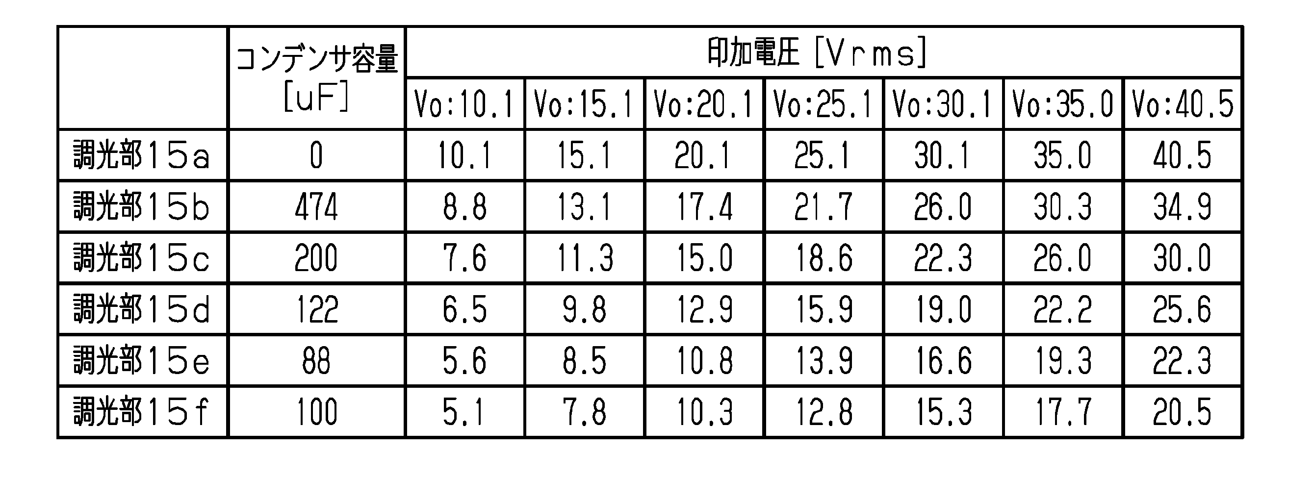
また、駆動電圧Voが20.1Vのとき、調光部15a~15fの印加電圧の最大値は20.1Vであり、最小値は10.3Vである。したがって、駆動電圧Voが10V以上20V以下のときに、調光部15a~15fの印加電圧のすべてが第1閾値電圧V1以上第2閾値電圧V2以下である状態が存在することが示唆される。
(4) When the driving voltage Vo is 20.1 V, the maximum value of the voltage applied to the light control units 15a to 15f is 20.1V, and the minimum value is 10.3V. Therefore, it is suggested that when the drive voltage Vo is 10 V or more and 20 V or less, there is a state where all of the applied voltages of the light control units 15 a to 15 f are the first threshold voltage V 1 or more and the second threshold voltage V 2 or less.
また、駆動電圧Voが40.5Vのとき、調光部15a~15fの印加電圧の最大値は40.5Vであり、最小値は20.5Vである。したがって、駆動電圧Voが20Vを超えるときに、調光部15a~15fの印加電圧のすべてが第2閾値電圧V2よりも大きくなる状態が存在する。
(4) When the drive voltage Vo is 40.5 V, the maximum value of the applied voltage to the light control units 15a to 15f is 40.5V, and the minimum value is 20.5V. Therefore, when the drive voltage Vo exceeds 20 V, there is a state where all of the applied voltages of the light control sections 15a to 15f become higher than the second threshold voltage V2.
したがって、実施例1の調光装置100によれば、不透明モードと階調モードと透明モードとの3種類の駆動モードの実現が可能であり、さらに、階調モードとして、調光部15の並ぶ方向における一端の調光部15aから他端の調光部15fに向けて、調光部15の並びの順に従って透明度が変化する表現が可能である。
Therefore, according to the light control device 100 of the first embodiment, it is possible to realize three types of drive modes, that is, the opaque mode, the gradation mode, and the transparent mode. In the direction, the expression in which the transparency changes in accordance with the order of arrangement of the light control units 15 from the light control unit 15a at one end to the light control unit 15f at the other end is possible.
<実施例2>
実施例2の調光装置は、第2実施形態に対応する調光装置である。実施例2における調光シート10の構成、すなわち、調光シート10の層構成および調光部15の配置およびサイズは実施例1と同様である。 <Example 2>
The dimmer according to the second embodiment is a dimmer corresponding to the second embodiment. The configuration of thelight control sheet 10 in the second embodiment, that is, the layer configuration of the light control sheet 10 and the arrangement and size of the light control section 15 are the same as those in the first embodiment.
実施例2の調光装置は、第2実施形態に対応する調光装置である。実施例2における調光シート10の構成、すなわち、調光シート10の層構成および調光部15の配置およびサイズは実施例1と同様である。 <Example 2>
The dimmer according to the second embodiment is a dimmer corresponding to the second embodiment. The configuration of the
[印加電圧の推移]
調光部15c,15dにはコンデンサ21を接続せず、調光部15a,15b,15e,15fの各々にコンデンサ21を接続して、調光装置110を構成した。そして、調光部15とコンデンサ21との直列回路に印加する駆動電圧Voの大きさを変化させて、調光部15a~15fの各々にかかる電圧の大きさを測定した。駆動電圧Voは、周波数が50Hzの矩形波の交流電圧である。表2に、調光部15a~15fに接続されているコンデンサ21の容量、駆動電圧Voの大きさ、および、調光部15a~15fの印加電圧の大きさを示す。 [Change in applied voltage]
Thedimmers 110 were constructed by connecting the capacitors 21 to the dimmers 15a, 15b, 15e, and 15f without connecting the condenser 21 to the dimmers 15c and 15d. Then, the magnitude of the voltage applied to each of the dimming units 15a to 15f was measured by changing the magnitude of the driving voltage Vo applied to the series circuit of the dimming unit 15 and the capacitor 21. The drive voltage Vo is a rectangular wave AC voltage having a frequency of 50 Hz. Table 2 shows the capacitance of the capacitor 21 connected to the light control units 15a to 15f, the magnitude of the drive voltage Vo, and the magnitude of the voltage applied to the light control units 15a to 15f.
調光部15c,15dにはコンデンサ21を接続せず、調光部15a,15b,15e,15fの各々にコンデンサ21を接続して、調光装置110を構成した。そして、調光部15とコンデンサ21との直列回路に印加する駆動電圧Voの大きさを変化させて、調光部15a~15fの各々にかかる電圧の大きさを測定した。駆動電圧Voは、周波数が50Hzの矩形波の交流電圧である。表2に、調光部15a~15fに接続されているコンデンサ21の容量、駆動電圧Voの大きさ、および、調光部15a~15fの印加電圧の大きさを示す。 [Change in applied voltage]
The
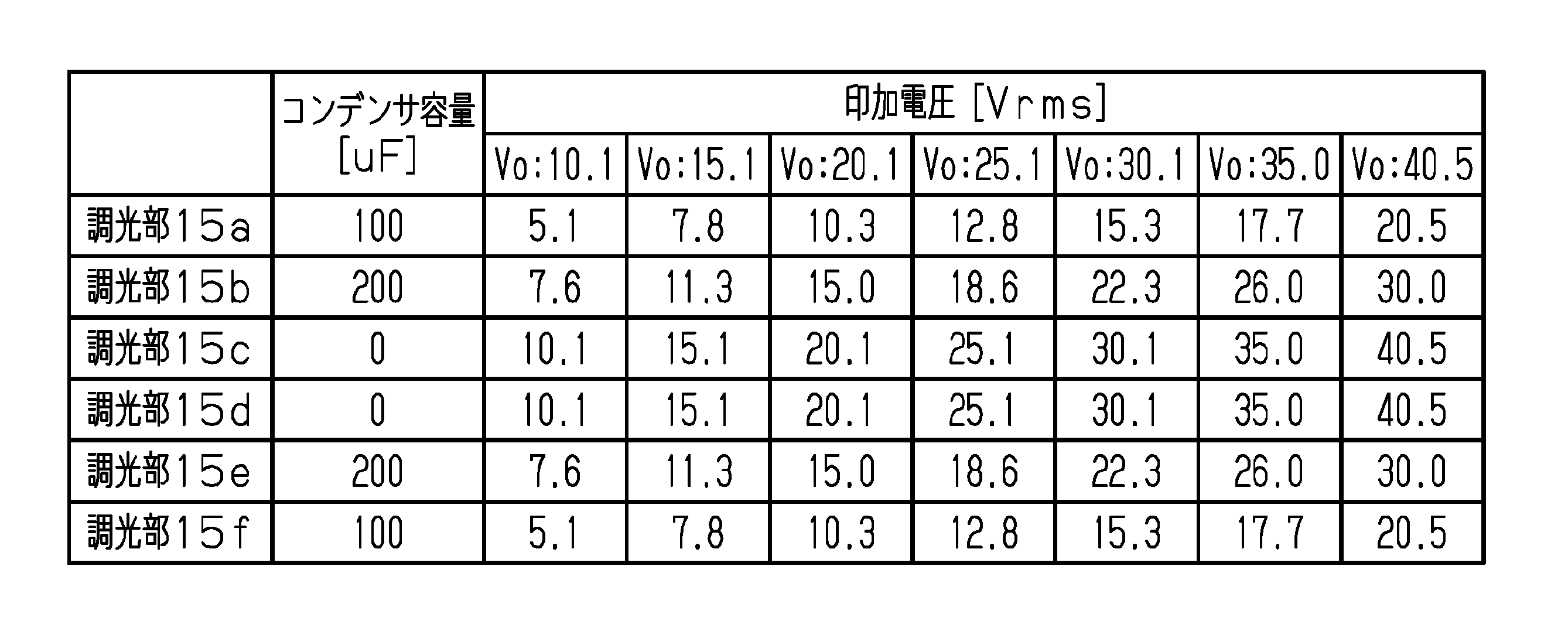
ここで、駆動電圧Voが10.1Vのとき、調光部15a~15fの印加電圧の最大値は10.1Vであり、最小値は5.1Vである。したがって、駆動電圧Voが10V未満のときに、調光部15a~15fの印加電圧のすべてが第1閾値電圧V1未満である状態が存在することが示唆される。
Here, when the driving voltage Vo is 10.1 V, the maximum value of the applied voltage of the light control units 15a to 15f is 10.1V, and the minimum value is 5.1V. Therefore, when the drive voltage Vo is less than 10 V, it is suggested that there is a state where all of the applied voltages of the light control units 15a to 15f are less than the first threshold voltage V1.
また、駆動電圧Voが20.1Vのとき、調光部15a~15fの印加電圧の最大値は20.1Vであり、最小値は10.3Vである。したがって、駆動電圧Voが10V以上20V以下のときに、調光部15a~15fの印加電圧のすべてが第1閾値電圧V1以上第2閾値電圧V2以下である状態が存在することが示唆される。
(4) When the driving voltage Vo is 20.1 V, the maximum value of the voltage applied to the light control units 15a to 15f is 20.1V, and the minimum value is 10.3V. Therefore, it is suggested that when the drive voltage Vo is 10 V or more and 20 V or less, there is a state where all of the applied voltages of the light control units 15 a to 15 f are the first threshold voltage V 1 or more and the second threshold voltage V 2 or less.
また、駆動電圧Voが40.5Vのとき、調光部15a~15fの印加電圧の最大値は40.5Vであり、最小値は20.5Vである。したがって、駆動電圧Voが20Vを超えるときに、調光部15a~15fの印加電圧のすべてが第2閾値電圧V2よりも大きくなる状態が存在する。
(4) When the drive voltage Vo is 40.5 V, the maximum value of the applied voltage to the light control units 15a to 15f is 40.5V, and the minimum value is 20.5V. Therefore, when the drive voltage Vo exceeds 20 V, there is a state where all of the applied voltages of the light control sections 15a to 15f become higher than the second threshold voltage V2.
したがって、実施例2の調光装置110によれば、不透明モードと階調モードと透明モードとの3種類の駆動モードの実現が可能であり、さらに、階調モードとして、調光部15の並ぶ方向における中央部の調光部15c,15dから両端の調光部15a,15fの各々に向けて、調光部15の並びの順に従って透明度が変化する表現が可能である。
Therefore, according to the light control device 110 of the second embodiment, it is possible to realize three types of drive modes, that is, the opaque mode, the gradation mode, and the transparent mode. The expression in which the transparency changes in accordance with the order of arrangement of the light control units 15 from the light control units 15c and 15d at the center in the direction to the light control units 15a and 15f at both ends in the direction is possible.
Claims (9)
- 駆動電圧を出力するように構成された駆動電圧出力部と、
前記駆動電圧出力部に前記駆動電圧の大きさを漸増または漸減させるように構成された制御部と、
前記駆動電圧出力部に対して並列に接続された複数の調光部であって、前記調光部の光透過率は、前記調光部の印加電圧の大きさに応じて変わる、前記複数の調光部を有する調光シートと、
前記複数の調光部のうちの1つと接続された分圧回路であって、各調光部に共通する前記駆動電圧を分圧して当該分圧回路に接続された前記調光部の印加電圧の大きさを他の少なくとも1つの前記調光部の印加電圧の大きさと異ならせるように構成された前記分圧回路と、
を備える調光装置。 A drive voltage output unit configured to output a drive voltage,
A control unit configured to gradually increase or decrease the magnitude of the drive voltage to the drive voltage output unit;
A plurality of light control units connected in parallel to the drive voltage output unit, wherein the light transmittance of the light control unit changes according to a magnitude of an applied voltage of the light control unit; A light control sheet having a light control section,
A voltage divider circuit connected to one of the plurality of light control units, wherein the drive voltage common to each light control unit is divided to apply a voltage to the light control unit connected to the voltage control circuit; The voltage dividing circuit configured to make the magnitude of the applied voltage different from the magnitude of the applied voltage of the at least one other light control unit;
A light control device comprising: - 前記分圧回路は、互いに異なる前記調光部に接続された複数の分圧回路のうちの1つであり、
前記複数の分圧回路の各々は、対応する前記調光部に直列接続されたコンデンサであり、
前記複数の分圧回路には、互いに異なる容量のコンデンサが含まれる
請求項1に記載の調光装置。 The voltage dividing circuit is one of a plurality of voltage dividing circuits connected to the dimming units different from each other,
Each of the plurality of voltage dividing circuits is a capacitor connected in series to the corresponding light control unit,
The light control device according to claim 1, wherein the plurality of voltage divider circuits include capacitors having different capacities. - 各調光部において、
印加電圧に対する光透過率の変化率を対象変化率と定義した場合に、
前記印加電圧が第1閾値電圧未満であるときの前記対象変化率、および、前記印加電圧が前記第1閾値電圧よりも大きい第2閾値電圧を超えるときの前記対象変化率の各々よりも、前記印加電圧が前記第1閾値電圧以上前記第2閾値電圧以下であるときの前記対象変化率が大きい
請求項1または2に記載の調光装置。 In each light control section,
When the rate of change of light transmittance with respect to applied voltage is defined as the target rate of change,
The target change rate when the applied voltage is less than a first threshold voltage, and each of the target change rates when the applied voltage exceeds a second threshold voltage larger than the first threshold voltage, The light control device according to claim 1 or 2, wherein the target change rate is large when an applied voltage is equal to or higher than the first threshold voltage and equal to or lower than the second threshold voltage. - 前記駆動電圧出力部が任意の大きさの前記駆動電圧を出力しているときの前記複数の調光部の印加電圧のうちの最大値と最小値との差が電圧差であり、
前記最大値が前記第1閾値電圧よりも小さいとき、前記電圧差は0を超え前記第1閾値電圧未満であり、
前記最大値が前記第1閾値電圧以上前記第2閾値電圧以下の範囲において所定値以上であるとき、前記電圧差は、0を超え、前記第1閾値電圧と前記第2閾値電圧との差以下である
請求項3に記載の調光装置。 The difference between the maximum value and the minimum value of the applied voltages of the plurality of light control units when the drive voltage output unit is outputting the drive voltage of an arbitrary magnitude is a voltage difference,
When the maximum value is smaller than the first threshold voltage, the voltage difference is greater than 0 and less than the first threshold voltage;
When the maximum value is equal to or greater than a predetermined value in a range equal to or greater than the first threshold voltage and equal to or less than the second threshold voltage, the voltage difference exceeds 0 and equal to or less than a difference between the first threshold voltage and the second threshold voltage. The light control device according to claim 3. - 前記分圧回路は、互いに異なる前記調光部に接続された複数の分圧回路のうちの1つであり、
前記複数の調光部は、1つの方向に沿って並び、
前記複数の調光部の並びの順に従って、前記調光部の印加電圧の大きさが変化するように、前記複数の分圧回路が構成されている
請求項1~4のいずれか一項に記載の調光装置。 The voltage dividing circuit is one of a plurality of voltage dividing circuits connected to the dimming units different from each other,
The plurality of light control units are arranged along one direction,
The voltage dividing circuit according to any one of claims 1 to 4, wherein the plurality of voltage dividing circuits are configured such that a magnitude of a voltage applied to the light adjusting unit changes according to an order of arrangement of the plurality of light adjusting units. The light control device as described in the above. - 前記複数の調光部が並ぶ方向における一方の端部に位置する前記調光部から他方の端部に位置する前記調光部に向けて、前記調光部の前記印加電圧が小さくなるように、前記複数の分圧回路が構成されている
請求項5に記載の調光装置。 From the dimming unit located at one end in the direction in which the plurality of dimming units are arranged, toward the dimming unit located at the other end, the applied voltage of the dimming unit is reduced. The dimming device according to claim 5, wherein the plurality of voltage dividing circuits are configured. - 前記複数の調光部が並ぶ方向における中央部に位置する前記調光部から両端に位置する前記調光部の各々に向けて、前記調光部の前記印加電圧が小さくなるように、前記複数の分圧回路が構成されている
請求項5に記載の調光装置。 The plurality of light control sections are arranged such that the applied voltage of the light control section decreases from the light control section located at the center in the direction in which the plurality of light control sections are arranged toward each of the light control sections located at both ends. The dimming device according to claim 5, wherein the voltage dividing circuit is configured as follows. - 前記調光シートは、すべての前記調光部が不透明な第1状態と、すべての前記調光部が透明な第2状態と、前記複数の調光部に互いに異なる光透過率を有する前記調光部が含まれる第3状態とを含み、
前記制御部が前記駆動電圧の大きさを漸増または漸減させることによって、前記第1状態と前記第2状態との間に前記第3状態を含むように、前記第1状態と前記第2状態との間で、各調光部の光透過率が連続的に変化する
請求項1~7のいずれか一項に記載の調光装置。 The light control sheet includes a first state in which all the light control units are opaque, a second state in which all the light control units are transparent, and the light control unit in which the plurality of light control units have different light transmittances. A third state in which the light unit is included,
The control unit gradually increases or decreases the magnitude of the drive voltage, so that the first state and the second state include the third state between the first state and the second state. The light control device according to any one of claims 1 to 7, wherein the light transmittance of each light control unit changes continuously during the period. - 前記調光シートは、液晶組成物を含む調光層と、前記調光層を挟む一対の透明電極層と、前記調光層および前記一対の透明電極層を挟む一対の透明支持層と、を備える
請求項1~8のいずれか一項に記載の調光装置。 The light control sheet includes a light control layer containing a liquid crystal composition, a pair of transparent electrode layers sandwiching the light control layer, and a pair of transparent support layers sandwiching the light control layer and the pair of transparent electrode layers. The dimming device according to any one of claims 1 to 8.
Priority Applications (3)
| Application Number | Priority Date | Filing Date | Title |
|---|---|---|---|
| EP19863666.4A EP3855243A4 (en) | 2018-09-21 | 2019-09-20 | Light adjusting device |
| CN201980058434.8A CN112673306A (en) | 2018-09-21 | 2019-09-20 | Light modulation device |
| US17/208,463 US11347089B2 (en) | 2018-09-21 | 2021-03-22 | Light control device |
Applications Claiming Priority (2)
| Application Number | Priority Date | Filing Date | Title |
|---|---|---|---|
| JP2018-177659 | 2018-09-21 | ||
| JP2018177659A JP7200565B2 (en) | 2018-09-21 | 2018-09-21 | dimmer |
Related Child Applications (1)
| Application Number | Title | Priority Date | Filing Date |
|---|---|---|---|
| US17/208,463 Continuation US11347089B2 (en) | 2018-09-21 | 2021-03-22 | Light control device |
Publications (1)
| Publication Number | Publication Date |
|---|---|
| WO2020059868A1 true WO2020059868A1 (en) | 2020-03-26 |
Family
ID=69887262
Family Applications (1)
| Application Number | Title | Priority Date | Filing Date |
|---|---|---|---|
| PCT/JP2019/037083 WO2020059868A1 (en) | 2018-09-21 | 2019-09-20 | Light adjusting device |
Country Status (5)
| Country | Link |
|---|---|
| US (1) | US11347089B2 (en) |
| EP (1) | EP3855243A4 (en) |
| JP (1) | JP7200565B2 (en) |
| CN (1) | CN112673306A (en) |
| WO (1) | WO2020059868A1 (en) |
Cited By (1)
| Publication number | Priority date | Publication date | Assignee | Title |
|---|---|---|---|---|
| JP2023023754A (en) * | 2021-08-06 | 2023-02-16 | 凸版印刷株式会社 | Light control system, light control sheet and screen |
Families Citing this family (2)
| Publication number | Priority date | Publication date | Assignee | Title |
|---|---|---|---|---|
| US20240027850A1 (en) * | 2022-07-25 | 2024-01-25 | Meta Platforms Technologies, Llc | Optical Devices with Active Components Coupled with Passive Components |
| EP4354215A1 (en) * | 2022-10-14 | 2024-04-17 | Dream Glass S. L. | Smart film for a display |
Citations (2)
| Publication number | Priority date | Publication date | Assignee | Title |
|---|---|---|---|---|
| JPS62209412A (en) * | 1986-03-10 | 1987-09-14 | Jiesu:Kk | Variable focal length liquid crystal lens for correcting astigmatism |
| JP2018060128A (en) | 2016-10-07 | 2018-04-12 | 大日本印刷株式会社 | Lighting control film and driving method of lighting control film |
Family Cites Families (19)
| Publication number | Priority date | Publication date | Assignee | Title |
|---|---|---|---|---|
| JPS61198119A (en) * | 1986-02-17 | 1986-09-02 | Dainippon Printing Co Ltd | Optical stop device |
| GB2198869B (en) * | 1986-12-19 | 1990-08-15 | Philips Electronic Associated | Matrix display devices |
| JPH1124637A (en) * | 1997-07-04 | 1999-01-29 | Optrex Corp | Drive method for simple matrix liquid crystal display |
| US6804040B2 (en) * | 2003-02-13 | 2004-10-12 | Research Frontiers Incorporated | Method and device for controlling voltage provided to a suspended particle device |
| US8094118B2 (en) * | 2005-03-02 | 2012-01-10 | University Of Southern California | Dynamic backlight scaling for power minimization in a backlit TFT-LCD |
| JP2007148071A (en) * | 2005-11-29 | 2007-06-14 | Tohoku Pioneer Corp | Driving device and driving method of light emitting display panel |
| JP4924716B2 (en) * | 2007-07-13 | 2012-04-25 | 富士通株式会社 | Liquid crystal display |
| JP2009192853A (en) * | 2008-02-15 | 2009-08-27 | Sharp Corp | Automatic dimming system |
| KR101539359B1 (en) * | 2009-02-05 | 2015-07-27 | 삼성디스플레이 주식회사 | Method for driving a light source, light source apparatus for performing the method, and display apparatus having the light source apparatus |
| KR20110057681A (en) * | 2009-11-24 | 2011-06-01 | 삼성전자주식회사 | Inverter circuit, backlight device and liquid crystal display using the same |
| CN203301391U (en) * | 2013-04-28 | 2013-11-20 | 史济云 | Intelligent power supply capable of continuously adjusting transparency of switchable glass or film |
| CN103616787B (en) * | 2013-12-04 | 2017-05-17 | 中航华东光电有限公司 | Liquid crystal lens and stereo display device with same |
| GB201423311D0 (en) * | 2014-12-29 | 2015-02-11 | Pilkington Group Ltd | Switchable device |
| US20160374165A1 (en) * | 2015-06-18 | 2016-12-22 | Innolux Corporation | Backlight module and liquid-crystal display device using the same |
| JP6170544B2 (en) * | 2015-12-16 | 2017-07-26 | 株式会社半導体エネルギー研究所 | Display device |
| KR102421609B1 (en) * | 2016-06-20 | 2022-07-18 | 다이니폰 인사츠 가부시키가이샤 | Light control film, driving method of light control film, light control member, vehicle |
| JP6733747B2 (en) * | 2017-02-02 | 2020-08-05 | 凸版印刷株式会社 | Dimmer |
| CN206757238U (en) * | 2017-05-18 | 2017-12-15 | 武汉晟华元玻璃科技有限公司 | A kind of liquid crystal light modulation film PDLC stepless continuous dimming power source circuits |
| CN206876994U (en) * | 2017-07-06 | 2018-01-12 | 珠海兴业应用材料科技有限公司 | A kind of repid discharge light modulation film power supply |
-
2018
- 2018-09-21 JP JP2018177659A patent/JP7200565B2/en active Active
-
2019
- 2019-09-20 CN CN201980058434.8A patent/CN112673306A/en active Pending
- 2019-09-20 WO PCT/JP2019/037083 patent/WO2020059868A1/en unknown
- 2019-09-20 EP EP19863666.4A patent/EP3855243A4/en active Pending
-
2021
- 2021-03-22 US US17/208,463 patent/US11347089B2/en active Active
Patent Citations (2)
| Publication number | Priority date | Publication date | Assignee | Title |
|---|---|---|---|---|
| JPS62209412A (en) * | 1986-03-10 | 1987-09-14 | Jiesu:Kk | Variable focal length liquid crystal lens for correcting astigmatism |
| JP2018060128A (en) | 2016-10-07 | 2018-04-12 | 大日本印刷株式会社 | Lighting control film and driving method of lighting control film |
Non-Patent Citations (1)
| Title |
|---|
| See also references of EP3855243A4 |
Cited By (2)
| Publication number | Priority date | Publication date | Assignee | Title |
|---|---|---|---|---|
| JP2023023754A (en) * | 2021-08-06 | 2023-02-16 | 凸版印刷株式会社 | Light control system, light control sheet and screen |
| JP7276389B2 (en) | 2021-08-06 | 2023-05-18 | 凸版印刷株式会社 | Dimming system and screen |
Also Published As
| Publication number | Publication date |
|---|---|
| US20210208437A1 (en) | 2021-07-08 |
| JP2020046645A (en) | 2020-03-26 |
| US11347089B2 (en) | 2022-05-31 |
| EP3855243A4 (en) | 2021-11-10 |
| EP3855243A1 (en) | 2021-07-28 |
| JP7200565B2 (en) | 2023-01-10 |
| CN112673306A (en) | 2021-04-16 |
Similar Documents
| Publication | Publication Date | Title |
|---|---|---|
| US11347089B2 (en) | Light control device | |
| CN101266374B (en) | Liquid crystal display and making method | |
| JP2018507471A (en) | Device for controlling light transmission | |
| US20210055582A1 (en) | Viewing angle control device and display apparatus | |
| CN107632727B (en) | Touch display screen, manufacturing method thereof, display device and driving method | |
| CN110568651A (en) | Touch control dimming device and vehicle window capable of touch control dimming | |
| JP6744593B2 (en) | Dimmer | |
| CN110476111B (en) | Liquid crystal dimming device and liquid crystal dimming method | |
| WO2018164282A1 (en) | Light control film, light control system, and light control member | |
| JP7477010B2 (en) | Liquid crystal light control device and its manufacturing method | |
| CN113454523B (en) | Dimming sheet, dimming device and dimming sheet management method | |
| JP2020076879A (en) | Light control film and drive circuit | |
| JP2017538967A (en) | Opacity switchable device | |
| JP2010049254A (en) | Liquid crystal display with split electrode structure | |
| US9564099B2 (en) | Bistable display systems and methods | |
| JP7395952B2 (en) | Light control sheet and light control device | |
| CN211826841U (en) | Peep-proof display device | |
| JP7383227B2 (en) | Light control sheet and light control device | |
| CN114585962B (en) | Light adjusting device and light adjusting sheet | |
| EP0686272A1 (en) | Self-referenced half-tone liquid crystal display | |
| JP3236737U (en) | Touch dimming device and touch dimmable car window | |
| CN218675579U (en) | Display device | |
| US11435861B2 (en) | Touch dimming device and touch dimming method | |
| CN103969852A (en) | Dynamic aging method for smectic liquid crystal display | |
| EP4354215A1 (en) | Smart film for a display |
Legal Events
| Date | Code | Title | Description |
|---|---|---|---|
| 121 | Ep: the epo has been informed by wipo that ep was designated in this application |
Ref document number: 19863666 Country of ref document: EP Kind code of ref document: A1 |
|
| NENP | Non-entry into the national phase |
Ref country code: DE |
|
| ENP | Entry into the national phase |
Ref document number: 2019863666 Country of ref document: EP Effective date: 20210421 |