WO2020059701A1 - Vibrating actuator - Google Patents
Vibrating actuator Download PDFInfo
- Publication number
- WO2020059701A1 WO2020059701A1 PCT/JP2019/036353 JP2019036353W WO2020059701A1 WO 2020059701 A1 WO2020059701 A1 WO 2020059701A1 JP 2019036353 W JP2019036353 W JP 2019036353W WO 2020059701 A1 WO2020059701 A1 WO 2020059701A1
- Authority
- WO
- WIPO (PCT)
- Prior art keywords
- damper
- inner guide
- mover
- case
- vibration
- Prior art date
Links
Images


Classifications
-
- B—PERFORMING OPERATIONS; TRANSPORTING
- B06—GENERATING OR TRANSMITTING MECHANICAL VIBRATIONS IN GENERAL
- B06B—METHODS OR APPARATUS FOR GENERATING OR TRANSMITTING MECHANICAL VIBRATIONS OF INFRASONIC, SONIC, OR ULTRASONIC FREQUENCY, e.g. FOR PERFORMING MECHANICAL WORK IN GENERAL
- B06B1/00—Methods or apparatus for generating mechanical vibrations of infrasonic, sonic, or ultrasonic frequency
- B06B1/02—Methods or apparatus for generating mechanical vibrations of infrasonic, sonic, or ultrasonic frequency making use of electrical energy
- B06B1/04—Methods or apparatus for generating mechanical vibrations of infrasonic, sonic, or ultrasonic frequency making use of electrical energy operating with electromagnetism
- B06B1/045—Methods or apparatus for generating mechanical vibrations of infrasonic, sonic, or ultrasonic frequency making use of electrical energy operating with electromagnetism using vibrating magnet, armature or coil system
-
- H—ELECTRICITY
- H02—GENERATION; CONVERSION OR DISTRIBUTION OF ELECTRIC POWER
- H02K—DYNAMO-ELECTRIC MACHINES
- H02K33/00—Motors with reciprocating, oscillating or vibrating magnet, armature or coil system
- H02K33/02—Motors with reciprocating, oscillating or vibrating magnet, armature or coil system with armatures moved one way by energisation of a single coil system and returned by mechanical force, e.g. by springs
-
- H—ELECTRICITY
- H02—GENERATION; CONVERSION OR DISTRIBUTION OF ELECTRIC POWER
- H02K—DYNAMO-ELECTRIC MACHINES
- H02K1/00—Details of the magnetic circuit
- H02K1/06—Details of the magnetic circuit characterised by the shape, form or construction
- H02K1/34—Reciprocating, oscillating or vibrating parts of the magnetic circuit
-
- H—ELECTRICITY
- H02—GENERATION; CONVERSION OR DISTRIBUTION OF ELECTRIC POWER
- H02K—DYNAMO-ELECTRIC MACHINES
- H02K33/00—Motors with reciprocating, oscillating or vibrating magnet, armature or coil system
- H02K33/16—Motors with reciprocating, oscillating or vibrating magnet, armature or coil system with polarised armatures moving in alternate directions by reversal or energisation of a single coil system
-
- G—PHYSICS
- G06—COMPUTING; CALCULATING OR COUNTING
- G06F—ELECTRIC DIGITAL DATA PROCESSING
- G06F3/00—Input arrangements for transferring data to be processed into a form capable of being handled by the computer; Output arrangements for transferring data from processing unit to output unit, e.g. interface arrangements
- G06F3/01—Input arrangements or combined input and output arrangements for interaction between user and computer
- G06F3/016—Input arrangements with force or tactile feedback as computer generated output to the user
Abstract
A vibrating actuator 1 comprises: a tubular case 2; an electromagnetic drive unit 3 provided inside the case 2; a movable element 4 capable of vibrating due to the electromagnetic drive unit 3; a first damper 40a having a plurality of arm parts 52a that support the movable element 4 from an inner surface of the case 2; and an inner guide 6a positioned closer to the center of the case 2 than the first damper 40a in the direction of a vibration axis O of the movable element 4 on the inner surface of the case 2, the inner guide 6a restricting movement of the first damper 40a that exceeds a prescribed range.
Description
本開示は、振動アクチュエータに関する。
The present disclosure relates to a vibration actuator.
従来から、携帯電話等の通信機器において、着信やアラームを人に知らせる方法として振動アクチュエータ(又は、振動モータ)を用いた振動による通知方法がある。そして、近年では、映画やゲーム、VR(Virtual Reality:仮想現実)の分野においても、例えば、アクションシーンの演出効果や、プレーヤーに対するフィードバック手段の一つとして振動アクチュエータが用いられており、振動により人の触覚を刺激することによってリアリティを向上させている。
(2) Conventionally, in a communication device such as a mobile phone, there is a notification method by vibration using a vibration actuator (or a vibration motor) as a method for notifying a person of an incoming call or an alarm. In recent years, in the fields of movies, games, and VR (Virtual Reality), for example, a vibration actuator has been used as one of effect effects for action scenes and one of feedback means to a player. Improving reality by stimulating the tactile sensation.
振動アクチュエータは、振動発生源として機器に組み込む用途の製品が多く、省スペース性を重視して小型化が望まれている。振動アクチュエータは錘等を含む可動子を電気的に往復移動させる構造を有しており、外部からの衝撃により可動子が過剰に振幅する場合がある。それにより、例えば、落下等の衝撃によって振動アクチュエータの内部で可動子と他の部品が干渉し、各部品に変形や破損が生じる等して動作不良や異音を生じるおそれがある。特に、携帯電話やゲームコントローラ等に使用される場合は、落下等の衝撃を避けることは難しい。
Many vibration actuators are used as devices for generating vibrations, and are required to be reduced in size with emphasis on space saving. The vibration actuator has a structure in which a mover including a weight or the like is reciprocated electrically, and the mover may excessively swing due to an external impact. As a result, for example, the mover and other components may interfere with each other inside the vibration actuator due to an impact such as dropping, and the components may be deformed or damaged, resulting in malfunction or abnormal noise. In particular, when used in a mobile phone, a game controller, or the like, it is difficult to avoid impact such as dropping.
これに対して、可動子が振動アクチュエータのケースに衝突するときの衝撃を抑制するためのクッションを設けた振動アクチュエータが開示されている(特許文献1、特許文献2参照)。この技術によれば、可動子の振動方向における衝撃を抑えることが可能となる。
On the other hand, a vibration actuator provided with a cushion for suppressing a shock when the mover collides with the case of the vibration actuator is disclosed (see Patent Documents 1 and 2). According to this technique, it is possible to suppress the impact in the vibration direction of the mover.
しかしながら、特許文献1及び特許文献2にて開示されているクッションは、可動子の振動方向において可動子より外側に配置されている。具体的にはケース両端端面の内側に設けられている。このような構成では、ケース内にクッションを設けるためのスペースを確保する必要があるため、振動アクチュエータの大型化を招くという問題がある。
However, the cushions disclosed in Patent Literature 1 and Patent Literature 2 are arranged outside the mover in the vibration direction of the mover. Specifically, it is provided inside both end surfaces of the case. In such a configuration, it is necessary to secure a space for providing a cushion in the case, and thus there is a problem that the size of the vibration actuator is increased.
また、特許文献1の振動アクチュエータは、可動子がガイドシャフトにより支持されていることから、可動子の移動は振動方向に規制されている。これに対して、特許文献2のように可動子が板バネ(いわゆる蝶ダンパ)で支持され、ガイドシャフトを有しない構造の振動アクチュエータでは(板バネの件としては特許文献3も参照)、ケースの径方向に衝撃が生じると可動子が径方向に移動してケース内側に接触するおそれがある。これに対して、ケースの径方向の内面にクッションを配置し、衝撃を低減しようすると、振動アクチュエータがさらに大型化するという問題が生じる。
振動 Further, in the vibration actuator of Patent Document 1, since the mover is supported by the guide shaft, the movement of the mover is restricted in the vibration direction. On the other hand, in a vibration actuator having a structure in which a movable element is supported by a leaf spring (a so-called butterfly damper) and does not have a guide shaft as in Patent Literature 2 (see also Patent Literature 3 regarding the leaf spring). If an impact occurs in the radial direction, the mover may move in the radial direction and come into contact with the inside of the case. On the other hand, if a cushion is arranged on the inner surface in the radial direction of the case to reduce the impact, there is a problem that the size of the vibration actuator is further increased.
本発明の実施形態は、このような問題点を解決するためになされたもので、その目的とするところは、振動アクチュエータの大型化を防ぎつつ、外部からの衝撃が生じた際の可動子の過剰振幅を防止し、部品同士の干渉による各部品の変形や破損を防止することができる振動アクチュエータを提供することにある。
Embodiments of the present invention have been made in order to solve such a problem, and an object of the present invention is to prevent an increase in the size of a vibration actuator and a movement of a movable element when an external impact occurs. An object of the present invention is to provide a vibration actuator capable of preventing excessive amplitude and preventing deformation and breakage of each component due to interference between components.
上記した目的を達成するために、本発明の実施形態の振動アクチュエータは、筒状のケースと、前記ケースの内部に設けられた電磁駆動部と、前記電磁駆動部により振動可能な可動子と、前記ケースの内部に前記可動子を支持する複数の腕部を有する板バネと、前記ケースの内部で前記可動子の振動軸方向において前記板バネより前記ケース中央側に位置して、前記板バネの動きを規制するインナーガイドと、を備える。
In order to achieve the above object, a vibration actuator according to an embodiment of the present invention includes a cylindrical case, an electromagnetic drive unit provided inside the case, and a movable element that can vibrate by the electromagnetic drive unit. A leaf spring having a plurality of arms for supporting the mover inside the case, and a leaf spring located on the case center side of the leaf spring in the vibration axis direction of the mover inside the case; And an inner guide that regulates the movement of the vehicle.
上述の振動アクチュエータにおいて、前記インナーガイドは、前記板バネの前記振動軸方向における動きを規制するものとしてもよい。
In the above-described vibration actuator, the inner guide may restrict movement of the leaf spring in the vibration axis direction.
また、上述の振動アクチュエータにおいて、前記インナーガイドは、前記板バネの前記振動軸方向に対して交差する方向における動きを規制するものとしてもよい。
In the above-described vibration actuator, the inner guide may restrict movement of the leaf spring in a direction intersecting with the vibration axis direction.
また、上述の振動アクチュエータにおいて、前記板バネの腕部は渦巻き形状をなし、前記インナーガイドは、前記板バネの渦巻き形状に対応し前記振動軸方向を中心とした螺旋状の段差部を有してもよい。
Further, in the above-described vibration actuator, the arm portion of the leaf spring has a spiral shape, and the inner guide has a spiral stepped portion corresponding to the spiral shape of the leaf spring and centered on the vibration axis direction. You may.
また、上述の振動アクチュエータにおいて、前記インナーガイドは、前記可動子の振動軸方向において前記電磁駆動部と前記板バネとの間に位置していてもよい。
In the above-described vibration actuator, the inner guide may be located between the electromagnetic drive unit and the leaf spring in a vibration axis direction of the mover.
また、上述の振動アクチュエータにおいて、前記インナーガイドは、内縁が前記電磁駆動部の内面よりも前記可動子側に突出していてもよい。
In addition, in the above-described vibration actuator, the inner guide may have an inner edge protruding toward the movable element side from an inner surface of the electromagnetic drive unit.
また、上述の振動アクチュエータにおいて、前記板バネは、前記可動子の一側端部を支持する第1板バネと、前記可動子の他側端部を支持する第2板バネと、を有し、前記インナーガイドは、前記第1板バネの動きを規制する第1インナーガイドと、前記第2板バネの動きを規制する第2インナーガイドと、を有してもよい。
In the above-described vibration actuator, the leaf spring has a first leaf spring that supports one end of the mover and a second leaf spring that supports another end of the mover. The inner guide may include a first inner guide that regulates the movement of the first leaf spring and a second inner guide that regulates the movement of the second leaf spring.
上記手段を用いる本発明の実施形態に係る振動アクチュエータによれば、振動アクチュエータの大型化を防ぎつつ、外部からの衝撃が生じた際の可動子の過剰振幅や部品同士の干渉を防止し、各部品の変形や破損を防止することができる。
According to the vibration actuator according to the embodiment of the present invention using the above means, while preventing an increase in the size of the vibration actuator, preventing excessive amplitude of the mover and interference between parts when an external impact occurs, Deformation and breakage of parts can be prevented.
以下、本発明の一実施形態を図面に基づき説明する。
Hereinafter, an embodiment of the present invention will be described with reference to the drawings.
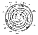
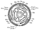
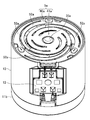
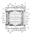
図1は本発明の実施形態に係る振動アクチュエータの分解斜視図、図2Aは振動アクチュエータの第1カバーケース及び第1弾性部材を省いた状態の上面図、図2Bはさらに第1ダンパを省いた状態の上面図、図3は振動アクチュエータの斜視図、図4は振動アクチュエータの断面図、図5Aはインナーガイドの斜視図、図5Bインナーガイドの上面図である。以下、これらの図に基づき振動アクチュエータの構成について説明する。
FIG. 1 is an exploded perspective view of a vibration actuator according to an embodiment of the present invention, FIG. 2A is a top view of the vibration actuator with a first cover case and a first elastic member omitted, and FIG. 2B further omits a first damper. 3 is a perspective view of the vibration actuator, FIG. 4 is a sectional view of the vibration actuator, FIG. 5A is a perspective view of the inner guide, and FIG. 5B is a top view of the inner guide. Hereinafter, the configuration of the vibration actuator will be described with reference to these drawings.
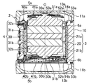
振動アクチュエータ1は、主に、外殻をなすケース2と、当該ケース2内に設けられた電磁駆動部3と、当該電磁駆動部3により振動可能な可動子4と、当該可動子4の両端をそれぞれ弾性支持する第1支持ユニット5a及び第2支持ユニット5bと、当該第1支持ユニット5a及び第2支持ユニット5bの動きを規制する第1インナーガイド6a及び第2インナーガイド6bと、から構成されている。当該振動アクチュエータ1は、例えば、携帯電話やスマートフォン等の携帯端末、ゲーム機のコントローラ等に搭載される。
The vibration actuator 1 mainly includes a case 2 that forms an outer shell, an electromagnetic drive unit 3 provided in the case 2, a movable element 4 that can be vibrated by the electromagnetic drive unit 3, and both ends of the movable element 4. A first support unit 5a and a second support unit 5b that elastically support the first and second inner guides 6a and 6b, respectively, for restricting the movement of the first support unit 5a and the second support unit 5b. Have been. The vibration actuator 1 is mounted on, for example, a mobile terminal such as a mobile phone or a smartphone, a controller of a game machine, or the like.
ケース2は、円筒状のケース本体10の両開口端が第1カバーケース11a及び第2カバーケース11bにより閉じられている。ケース本体10、第1カバーケース11a、及び第2カバーケース11bはそれぞれABS等の樹脂からなる。ケース本体10の外面には、図示しないリード線が接続されるターミナル12が形成されている。
In the case 2, both open ends of the cylindrical case body 10 are closed by the first cover case 11a and the second cover case 11b. The case body 10, the first cover case 11a, and the second cover case 11b are each made of a resin such as ABS. A terminal 12 to which a lead wire (not shown) is connected is formed on the outer surface of the case body 10.
電磁駆動部3は、ケース2の内部に配置された円筒状の軟磁性材料でなるヨーク20と、ヨーク20の内面にヨーク20と電気的に絶縁された状態で取り付けられた第1コイル21a及び第2コイル21bと、を有する。
The electromagnetic drive unit 3 includes a cylindrical yoke 20 made of a soft magnetic material disposed inside the case 2, a first coil 21 a attached to an inner surface of the yoke 20 while being electrically insulated from the yoke 20. A second coil 21b.
ヨーク20は、図4に示すように、振動軸O方向の中央位置において、径方向内側に突出した凸部22を有している。凸部22は、ヨーク20の内面に突設されており、振動軸Oの回りに3か所、120°ピッチの等間隔に設けられている。凸部22は、例えばダボ加工により形成される。
As shown in FIG. 4, the yoke 20 has a convex portion 22 protruding radially inward at a center position in the vibration axis O direction. The protruding portions 22 are protruded from the inner surface of the yoke 20, and are provided at three places around the vibration axis O at regular intervals of 120 ° pitch. The protrusion 22 is formed by, for example, doweling.
第1コイル21a及び第2コイル21bはヨーク20の内面に沿って巻回されている。当該第1コイル21a及び第2コイル21bはそれぞれターミナル12からの通電により磁場を発生可能である。第1コイル21a及び第2コイル21bはヨーク20の凸部22に当接し、振動軸O方向の位置決めがなされた状態で、接着材等を用いてヨーク20に取り付けられる。
The first coil 21a and the second coil 21b are wound along the inner surface of the yoke 20. The first coil 21a and the second coil 21b can generate a magnetic field when energized from the terminal 12, respectively. The first coil 21a and the second coil 21b are attached to the yoke 20 with an adhesive or the like in a state in which the first coil 21a and the second coil 21b are in contact with the protrusion 22 of the yoke 20 and are positioned in the vibration axis O direction.
可動子4は、第1コイル21a及び第2コイル21bに包囲され、振動軸Oに沿って振動するよう配置されている。可動子4は、円板状のマグネット30と、マグネット30を挟むように配置された円板状の第1ポールピース31a、第2ポールピース31bと、マグネット30、第1ポールピース31a、第2ポールピース31bを挟むように配置される第1マス(ウエイト、錘)32a、第2マス(ウエイト、錘)32bと、から構成されている。
The mover 4 is surrounded by the first coil 21a and the second coil 21b, and is arranged to vibrate along the vibration axis O. The mover 4 includes a disc-shaped magnet 30, a disc-shaped first pole piece 31a and a second pole piece 31b arranged so as to sandwich the magnet 30, a magnet 30, a first pole piece 31a, and a second pole piece 31b. It comprises a first mass (weight, weight) 32a and a second mass (weight, weight) 32b arranged so as to sandwich the pole piece 31b.
マグネット30は着磁方向が振動軸O方向である。第1ポールピース31a、第2ポールピース31bは、軟磁性材料でなり、マグネット30の磁気吸着力及び接着剤等により、マグネット30に取り付けられている。第1マス32aと第2マス32bは非磁性体からなり、それぞれ接着剤等により、第1ポールピース31a、第2ポールピース31bに取り付けられている。このため、可動子4を構成するマグネット30、第1ポールピース31a、第2ポールピース31b、第1マス32a、第2マス32bは一体化されている。なお、これらのマグネット30、第1ポールピース31a、第2ポールピース31b、第1マス32a、第2マス32bの一体化は、上述した磁気吸着力や接着剤による取り付けに限定されるものではない。ねじ止め等の機械的手段やその他の手段により固定することにより、一体化してもよい。第1マス32a、第2マス32bは、第1ポールピース31a、第2ポールピース31bとの当接面が平坦に形成されているが、この当接面と逆側の面は、振動軸Oを中心軸とし、その中心軸上の先端部33a、33bが最も外方に突出した螺旋形状に形成されている。
The magnet 30 is magnetized in the vibration axis O direction. The first pole piece 31a and the second pole piece 31b are made of a soft magnetic material, and are attached to the magnet 30 by a magnetic attraction force of the magnet 30 and an adhesive. The first mass 32a and the second mass 32b are made of a non-magnetic material, and are respectively attached to the first pole piece 31a and the second pole piece 31b by an adhesive or the like. For this reason, the magnet 30, the first pole piece 31a, the second pole piece 31b, the first mass 32a, and the second mass 32b that constitute the mover 4 are integrated. The integration of the magnet 30, the first pole piece 31a, the second pole piece 31b, the first mass 32a, and the second mass 32b is not limited to the above-described attachment using the magnetic attraction force or the adhesive. . You may integrate by fixing with mechanical means, such as screwing, or other means. The first mass 32a and the second mass 32b have flat contact surfaces with the first pole piece 31a and the second pole piece 31b, and the surface opposite to the contact surface has a vibration axis O. Is the central axis, and the tip portions 33a and 33b on the central axis are formed in a spiral shape projecting outward most.
このように構成された可動子4は、振動軸O方向における両端部、即ち第1マス32a及び第2マス32bのそれぞれの先端部33a、33bが第1支持ユニット5a及び第2支持ユニット5bにより支持されている。
In the mover 4 configured as described above, both ends in the direction of the vibration axis O, that is, the distal ends 33a and 33b of the first mass 32a and the second mass 32b are respectively formed by the first support unit 5a and the second support unit 5b. Supported.
第1支持ユニット5aは、第1ダンパ40a(第1板バネ)と、当該第1ダンパ40aの一面に設けられた第1弾性部材41aと、から構成されている。
The first support unit 5a includes a first damper 40a (first leaf spring) and a first elastic member 41a provided on one surface of the first damper 40a.
図2Aに示すように、第1ダンパ40aは、孔50a(図4に図示)を有する支持部51aが中央部に形成されている。第1ダンパ40aは孔50aを通して可動子4と連結されている。詳しくは、孔50aに第1マス32aの先端部33aを挿通し、当該先端部33aが押し潰されることでかしめられている。なお、第1ダンパ40aと可動子4との固定手段はかしめに限定されるものではなく、ねじ止めや接着等の他の方法により固定(連結)することもできる。
AAs shown in FIG. 2A, the first damper 40a has a support portion 51a having a hole 50a (shown in FIG. 4) formed at the center. The first damper 40a is connected to the mover 4 through the hole 50a. More specifically, the distal end 33a of the first mass 32a is inserted into the hole 50a, and the distal end 33a is squashed by being crushed. The means for fixing the first damper 40a and the mover 4 is not limited to caulking, but may be fixed (coupled) by another method such as screwing or bonding.
また第1ダンパ40aは、支持部51aから外周へ渦巻き状に延びる3つの腕部52aを有している。各腕部52aは振動軸Oの回りに120°ピッチで等間隔に形成されている。そして、各腕部52aの外周端はケース本体10の内面に沿った環状の枠部53aに連結されている。当該枠部53aは、振動軸Oの回りに120°ピッチの位置にて、ケース本体10の内面の3か所にて径方向内側に突出しているフランジ部13a(図2Bに図示)にて連結されている。詳しくは、フランジ部13aから立設したボス部14aを第1ダンパ40aの枠部53aに形成された貫通孔に挿通した状態で、ボス部14aの先端を加熱・加圧し、押し潰すことでかしめている。枠部53aと第1ダンパ40aとの固定手段はかしめに限定されるものではなく、ねじ止めや接着等の他の方法により固定(連結)することもできる。
The first damper 40a has three arms 52a spirally extending from the support portion 51a to the outer periphery. The arms 52a are formed at equal intervals around the vibration axis O at a pitch of 120 °. The outer peripheral end of each arm 52a is connected to an annular frame 53a along the inner surface of the case body 10. The frame portion 53a is connected at three positions on the inner surface of the case main body 10 by flange portions 13a (shown in FIG. 2B) protruding radially inward at three positions on the inner surface of the case body 10 around the vibration axis O. Have been. More specifically, the tip of the boss 14a is heated and pressurized and crushed while the boss 14a standing from the flange 13a is inserted into the through hole formed in the frame 53a of the first damper 40a. Squeezed. The means for fixing the frame portion 53a and the first damper 40a is not limited to caulking, but may be fixed (connected) by another method such as screwing or bonding.
第1ダンパ40aは、金属の一枚ないし複数枚の板バネで構成されており、例えば本実施形態ではステンレス(バネ材)の薄板を加工したものを使用している。第1ダンパ40aの材料は、金属に限らず樹脂や繊維を含む複合素材であってもよい。疲労に強く、可撓性に優れた材料が望ましい。
The first damper 40a is composed of one or a plurality of leaf springs made of metal. For example, in this embodiment, a thin plate made of stainless steel (spring material) is used. The material of the first damper 40a is not limited to metal, but may be a composite material containing resin or fiber. A material that is resistant to fatigue and excellent in flexibility is desirable.
このように構成された第1ダンパ40aは、振動軸O方向及び当該振動軸Oに垂直な径方向を含む交差方向において所定の範囲で弾性変形可能である。なお、この所定の範囲は、振動アクチュエータ1として通常に使用した場合の可動子4の振幅範囲に相当する。従って、当該所定の範囲は、少なくとも第1ダンパ40aがケース2に接触しない範囲であり、第1ダンパ40aの弾性変形の限界を超えない範囲である。
1 The first damper 40a thus configured is elastically deformable within a predetermined range in a cross direction including the direction of the vibration axis O and a radial direction perpendicular to the vibration axis O. This predetermined range corresponds to the amplitude range of the mover 4 when normally used as the vibration actuator 1. Therefore, the predetermined range is a range where at least the first damper 40a does not contact the case 2 and does not exceed the limit of the elastic deformation of the first damper 40a.
第1弾性部材41aは、図3に示すように、第1ダンパ40aの支持部51aから各腕部52aの一定の範囲までの形状に沿った外形の板状をなし、第1ダンパ40aの一面に固定されている。詳しくは、第1弾性部材41aは、第1ダンパ40a上に積層された、接着剤でなる第1接着層と、PE(ポリエチレン)でなるPE層と、接着剤でなる第2接着層と、エラストマ(エラストマとしては、熱可塑性ポリウレタンエラストマー(TPU)があるが限定するものではない)でなるエラストマ層とからなっている。そして、第1弾性部材41aの弾性変形(本実施形態では、PE層のずり変形、エラストマ層の曲げ変形)により、第1ダンパ40aの制振を行う。第1弾性部材41aと第1ダンパ40aとの固定手段は、上記の接着によるものに限定されず、樹脂製の第1弾性部材41aを第1ダンパ40aに熱溶着する等、その他の固定手段を用いてもよい。
As shown in FIG. 3, the first elastic member 41a has a plate shape having an outer shape along the shape from the support portion 51a of the first damper 40a to a certain range of each arm 52a, and one surface of the first damper 40a. It is fixed to. Specifically, the first elastic member 41a includes a first adhesive layer made of an adhesive, a PE layer made of PE (polyethylene), and a second adhesive layer made of an adhesive, which are stacked on the first damper 40a. An elastomer layer made of an elastomer (the elastomer includes, but is not limited to, a thermoplastic polyurethane elastomer (TPU)). Then, the first damper 40a is damped by elastic deformation of the first elastic member 41a (in the present embodiment, shear deformation of the PE layer and bending deformation of the elastomer layer). The fixing means for fixing the first elastic member 41a and the first damper 40a is not limited to the above-mentioned bonding method, and other fixing means such as heat welding the first elastic member 41a made of resin to the first damper 40a may be used. May be used.
第2支持ユニット5bも、第1支持ユニット5aと同様の構成をなしており、第2ダンパ40b(第2板バネ)及び第2弾性部材41bを有している。なお、本実施形態において第2ダンパ40bと第1ダンパ40aとが同一形状、同材料からなり、第2弾性部材41bと第1弾性部材41aとが同一形状、同材料である。図4に示すように、第2ダンパ40bの3つの腕部52bは孔50bが形成された支持部51bから環状の枠部53bまで延びている。そして、第2ダンパ40bは、孔50bに第2マス32bの先端部33bが挿入され押し潰してかしめられることで可動子4と連結されている。また、第2ダンパ40bは、環状の枠部53bがケース本体10内面から突出している3つのフランジ部13bと、枠部53bに形成された貫通孔をフランジ部13bのボス部14bが挿通し押し潰されてかしめられることで連結されている。なお、第2ダンパ40bの各腕部52bの渦巻き方向は、第1ダンパ40aの各腕部52aの渦巻き方向と逆をなしている。これにより、振動時に可動子4は第1ダンパ40a及び第2ダンパ40bから各々逆方向のトルクを受けるため、振動軸O方向に変位しても振動軸O回りに回転しない。
The second support unit 5b also has the same configuration as the first support unit 5a, and has a second damper 40b (second leaf spring) and a second elastic member 41b. In this embodiment, the second damper 40b and the first damper 40a have the same shape and the same material, and the second elastic member 41b and the first elastic member 41a have the same shape and the same material. As shown in FIG. 4, the three arm portions 52b of the second damper 40b extend from the support portion 51b in which the hole 50b is formed to the annular frame portion 53b. The second damper 40b is connected to the mover 4 by inserting the distal end portion 33b of the second mass 32b into the hole 50b, crushing it, and caulking. The second damper 40b has three flange portions 13b whose annular frame portions 53b protrude from the inner surface of the case body 10 and boss portions 14b of the flange portions 13b that push through holes formed in the frame portions 53b. It is connected by being crushed and caulked. The spiral direction of each arm 52b of the second damper 40b is opposite to the spiral direction of each arm 52a of the first damper 40a. As a result, since the mover 4 receives torques in the opposite directions from the first damper 40a and the second damper 40b during vibration, the mover 4 does not rotate around the vibration axis O even when displaced in the vibration axis O direction.
(第1インナーガイド6a、第2インナーガイド6b)
第1インナーガイド6aは振動アクチュエータ1の振動軸O方向の一側であり、第1支持ユニット5aよりも振動軸O方向の他側(ケース2中央側)に設けられている。第2インナーガイド6bは振動アクチュエータ1の振動軸O方向の他側であり、第2支持ユニット5bよりも振動軸O方向の一側(ケース2中央側)に設けられている。つまり、図4に示すように、第1インナーガイド6a及び第2インナーガイド6bは、ケース2内において第1支持ユニット5a及び第2支持ユニット5bよりも振動軸O方向中央側に設けられている。第1インナーガイド6a及び第2インナーガイド6bは、例えばABS等の樹脂で形成されている。ただし第1インナーガイド6a及び第2インナーガイド6bの材料は樹脂に限定されるものでない。 (Firstinner guide 6a, second inner guide 6b)
The firstinner guide 6a is provided on one side in the vibration axis O direction of the vibration actuator 1, and is provided on the other side in the vibration axis O direction (the center side of the case 2) than the first support unit 5a. The second inner guide 6b is provided on the other side of the vibration actuator 1 in the direction of the vibration axis O, and is provided on one side in the direction of the vibration axis O (center side of the case 2) than the second support unit 5b. That is, as shown in FIG. 4, the first inner guide 6a and the second inner guide 6b are provided in the case 2 closer to the center in the vibration axis O direction than the first support unit 5a and the second support unit 5b. . The first inner guide 6a and the second inner guide 6b are formed of, for example, a resin such as ABS. However, the material of the first inner guide 6a and the second inner guide 6b is not limited to resin.
第1インナーガイド6aは振動アクチュエータ1の振動軸O方向の一側であり、第1支持ユニット5aよりも振動軸O方向の他側(ケース2中央側)に設けられている。第2インナーガイド6bは振動アクチュエータ1の振動軸O方向の他側であり、第2支持ユニット5bよりも振動軸O方向の一側(ケース2中央側)に設けられている。つまり、図4に示すように、第1インナーガイド6a及び第2インナーガイド6bは、ケース2内において第1支持ユニット5a及び第2支持ユニット5bよりも振動軸O方向中央側に設けられている。第1インナーガイド6a及び第2インナーガイド6bは、例えばABS等の樹脂で形成されている。ただし第1インナーガイド6a及び第2インナーガイド6bの材料は樹脂に限定されるものでない。 (First
The first
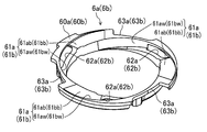
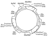
図2B及び図5A、図5Bに示すように、第1インナーガイド6aは、ケース本体10の内面に沿った環状の枠部60aを有しており、その枠部60aの振動軸O回り120°ピッチの3か所に、ケース本体10の径方向内側且つ振動軸O方向他側に向けて螺旋状に傾斜した段差部61aが形成されている。当該段差部61aの螺旋形状は、第1ダンパ40aの各腕部52aの渦巻き形状の外周側(基端側)の部分に沿った形状であり、且つ第1ダンパ40aが所定の範囲で弾性変形している際には各腕部52aに接触することなく、当該第1ダンパ40aの変形が所定の範囲を超えた際には各腕部52aと接触する間隔を有している。
As shown in FIGS. 2B, 5A, and 5B, the first inner guide 6a has an annular frame portion 60a along the inner surface of the case main body 10, and the frame portion 60a is rotated by 120 ° around the vibration axis O. At three positions of the pitch, step portions 61a are formed, which are spirally inclined toward the inside in the radial direction of the case main body 10 and the other side in the vibration axis O direction. The spiral shape of the stepped portion 61a is a shape along the outer peripheral side (base end side) of the spiral shape of each arm 52a of the first damper 40a, and the first damper 40a is elastically deformed within a predetermined range. When the first damper 40a is deformed beyond a predetermined range, there is an interval at which the first damper 40a contacts each arm 52a without contacting each arm 52a.
詳しくは、各段差部61aは、ケース本体10の内面と平行な面をなす側壁61awと、当該側壁61awから径方向内側に延びる底部61abと、から構成されている。各底部61abの内縁は上面視においてケース本体10の内面と同軸の内周円(同心円)を形成しており、各側壁61awはケース本体10の内面側から当該内周円に向けた円弧状をなしている。第1ダンパ40aが振動軸Oの交差方向において所定の範囲を超えて変形した場合には側壁61awと接触することで当該交差方向の動きを規制し、第1ダンパ40aが振動軸O方向に所定の範囲を超えて変形した場合には底部61abと接触することで当該振動軸O方向の動きを規制する。
Specifically, each step portion 61a includes a side wall 61aw that forms a plane parallel to the inner surface of the case main body 10, and a bottom portion 61ab that extends radially inward from the side wall 61aw. The inner edge of each bottom portion 61ab forms an inner peripheral circle (concentric circle) coaxial with the inner surface of the case main body 10 when viewed from above, and each side wall 61aw has an arc shape from the inner surface side of the case main body 10 toward the inner peripheral circle. No. When the first damper 40a is deformed beyond a predetermined range in the cross direction of the vibration axis O, the movement in the cross direction is restricted by contacting the side wall 61aw, and the first damper 40a moves in the predetermined direction in the vibration axis O direction. When it is deformed beyond the range, the movement in the direction of the vibration axis O is restricted by contacting the bottom 61ab.
また、各段差部61aには軽量化のための孔62aが形成されている。さらに、第1インナーガイド6aの枠部60aの外周縁側にはケース本体10の各フランジ部13aの形状に合わせて3か所に当該フランジ部13aの形状に沿った切欠部63aが形成されている。
孔 Further, a hole 62a for reducing the weight is formed in each step portion 61a. Furthermore, cutouts 63a are formed on the outer peripheral edge side of the frame portion 60a of the first inner guide 6a at three locations along the shape of the flange portions 13a of the case body 10 in accordance with the shape of the flange portions 13a. .
このように構成された第1インナーガイド6aは、枠部60aが形成する内周円内を可動子4が振動軸O方向に進退移動可能である。また、当該枠部60aが形成する内周円の内縁は第1コイル21a及び第2コイル21bよりも径方向内側に突出している。
可 動 The first inner guide 6a configured as described above allows the mover 4 to move forward and backward in the direction of the vibration axis O within the inner circumferential circle formed by the frame portion 60a. The inner edge of the inner circumference circle formed by the frame portion 60a protrudes radially inward from the first coil 21a and the second coil 21b.
第2インナーガイド6bは第1インナーガイド6aと同一形状であり、第2インナーガイド6bについても第1インナーガイド6aと同様の構成をなしている。つまり、図5A、図5Bにてかっこ書きの符号で示すように、第1インナーガイド6aと第2インナーガイド6bの各部は対応している。詳しくは第2インナーガイド6bは環状の枠部60bを有しており、枠部60bに側壁61bwと底部61bbを有する段差部61bが形成されている。また、各段差部61bには孔62bが形成され、枠部60bには切欠部63bが形成されている。
The second inner guide 6b has the same shape as the first inner guide 6a, and the second inner guide 6b has the same configuration as the first inner guide 6a. That is, as shown by parenthesized symbols in FIGS. 5A and 5B, the respective portions of the first inner guide 6a and the second inner guide 6b correspond to each other. More specifically, the second inner guide 6b has an annular frame portion 60b, and a step portion 61b having a side wall 61bw and a bottom portion 61bb is formed in the frame portion 60b. A hole 62b is formed in each step 61b, and a cutout 63b is formed in the frame 60b.
(作動)
以上のように構成された振動アクチュエータ1は、第1コイル21a及び第2コイル21bに通電していない状態では、図4に示すように、第1ダンパ40a及び第2ダンパ40bで支持される可動子4は、第1コイル21a及び第2コイル21bの中央に位置している。 (Actuation)
In the state where thefirst coil 21a and the second coil 21b are not energized, the vibration actuator 1 configured as described above is movable supported by the first damper 40a and the second damper 40b as shown in FIG. The child 4 is located at the center of the first coil 21a and the second coil 21b.
以上のように構成された振動アクチュエータ1は、第1コイル21a及び第2コイル21bに通電していない状態では、図4に示すように、第1ダンパ40a及び第2ダンパ40bで支持される可動子4は、第1コイル21a及び第2コイル21bの中央に位置している。 (Actuation)
In the state where the
可動子4を振動させる際には、ターミナル12を介して、第1コイル21a及び第2コイル21bに、交互に逆極性の磁界を発生する向きに交流を通電させる。即ち、第1コイル21a及び第2コイル21bの隣り合う部分に同極が発生するようになっている。
(4) When the mover 4 is vibrated, an alternating current is applied to the first coil 21a and the second coil 21b via the terminal 12 in such a direction as to alternately generate a magnetic field of opposite polarity. That is, the same polarity is generated in adjacent portions of the first coil 21a and the second coil 21b.
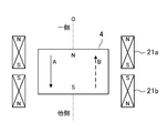
例えば図6に示す極性の場合、可動子4には実線矢印Aで示す振動軸O方向の他側(図6における下方)への推力が発生し、第1コイル21a及び第2コイル21bへ流す電流を反転させれば、可動子4には点線矢印Bで示す振動軸O方向の一側(図6における上方)への推力が発生する。
For example, in the case of the polarity shown in FIG. 6, a thrust is generated on the mover 4 in the other direction (downward in FIG. 6) in the vibration axis O indicated by the solid arrow A, and flows to the first coil 21a and the second coil 21b. When the current is reversed, a thrust is generated in the mover 4 toward one side (upward in FIG. 6) in the direction of the vibration axis O indicated by the dotted arrow B.
このように、第1コイル21a及び第2コイル21bに交流を通電させれば、可動子4は第1ダンパ40a及び第2ダンパ40bによる付勢力を両側から受けながら、振動軸Oに沿って振動する。
As described above, when the alternating current is applied to the first coil 21a and the second coil 21b, the mover 4 vibrates along the vibration axis O while receiving the urging force from the first damper 40a and the second damper 40b from both sides. I do.
ところで、可動子4に発生する推力は、基本的にはフレミングの左手の法則に基づいて与えられる推力に準じられる。本実施形態では、第1コイル21a、第2コイル21bがケース2に固定されているので、マグネット30等が取り付けられた可動子4に第1コイル21a、第2コイル21bに発生する力の反力としての推力が発生する。
By the way, the thrust generated in the mover 4 basically conforms to the thrust given based on Fleming's left hand rule. In the present embodiment, since the first coil 21a and the second coil 21b are fixed to the case 2, the movable member 4 to which the magnet 30 and the like are attached has a counterforce of the force generated in the first coil 21a and the second coil 21b. Thrust as force is generated.
よって、推力に寄与するのは、可動子4のマグネット30の磁束の水平成分(マグネット30の軸方向に直交する成分)である。そして、ヨーク20はマグネット30の磁束の水平成分を増大するものである。
Therefore, what contributes to the thrust is the horizontal component of the magnetic flux of the magnet 30 of the mover 4 (the component orthogonal to the axial direction of the magnet 30). The yoke 20 increases the horizontal component of the magnetic flux of the magnet 30.
このように可動子4の通常の振動時は、第1ダンパ40a及び第2ダンパ40bは振動軸O方向及び径方向において所定の範囲で弾性変形し、第1インナーガイド6a及び第2インナーガイド6bに接触することはない。
As described above, during normal vibration of the mover 4, the first damper 40a and the second damper 40b are elastically deformed within a predetermined range in the vibration axis O direction and the radial direction, and the first inner guide 6a and the second inner guide 6b Never touch.
一方で、例えば振動アクチュエータ1を搭載した機器が落下した場合等で振動アクチュエータ1に外部から衝撃が加わると、可動子4が過剰な振幅で動き第1ダンパ40a及び第2ダンパ40bが所定の範囲を超えた動きをすることがあるが、第1インナーガイド6a及び第2インナーガイド6bと接触することでこの動きが規制される。
On the other hand, when an external impact is applied to the vibration actuator 1 when, for example, a device on which the vibration actuator 1 is mounted falls, the mover 4 moves with an excessive amplitude, and the first damper 40a and the second damper 40b move within a predetermined range. May be exceeded, but this movement is restricted by contacting the first inner guide 6a and the second inner guide 6b.
具体的には図7Aに示すように、可動子4が振動軸O方向一側に過剰振幅し、第1ダンパ40a及び第2ダンパ40bが所定の範囲を超える動きをした場合、第2ダンパ40bの腕部53bが、第2インナーガイド6bの段差部61bの底部61bbと接触する。これにより、可動子4がそれ以上振動軸O方向一側に移動することが規制され、可動子4はケース2(第1カバーケース11a)と接触することが防止される。
More specifically, as shown in FIG. 7A, when the mover 4 excessively swings to one side in the vibration axis O direction and the first damper 40a and the second damper 40b move beyond a predetermined range, the second damper 40b Arm 53b contacts the bottom 61bb of the step 61b of the second inner guide 6b. This restricts the mover 4 from further moving to one side in the vibration axis O direction, and prevents the mover 4 from contacting the case 2 (the first cover case 11a).
また、図7Bに示すように、可動子4が振動軸O方向他側に過剰振幅し、第1ダンパ40a及び第2ダンパ40bが所定の範囲を超える動きをした場合、第1ダンパ40aの腕部52aが、第1インナーガイド6aの段差部61aの底部61abと接触する。これにより、可動子4がそれ以上振動軸O方向他側に移動することが規制され、可動子4はケース2(第2カバーケース11b)と接触することが防止される。
Also, as shown in FIG. 7B, when the mover 4 excessively swings to the other side in the direction of the vibration axis O and the first damper 40a and the second damper 40b move beyond a predetermined range, the arm of the first damper 40a The portion 52a contacts the bottom 61ab of the step 61a of the first inner guide 6a. This restricts the mover 4 from further moving to the other side in the vibration axis O, and prevents the mover 4 from contacting the case 2 (the second cover case 11b).
図示しないが、ケース2に径方向の衝撃が加わった場合は、可動子4も径方向に移動する。このような場合に、可動子4が径方向に移動し、第1ダンパ40a及び第2ダンパ40bが径方向における所定の範囲を超える動きをすると、第1ダンパ40a及び第2ダンパ40bの腕部52a,52bが、第1インナーガイド6a及び第2インナーガイド6bの段差部61a、61bの側壁61aw、61bwと接触する。これにより、可動子4がそれ以上ケース2の径方向に移動することが規制され、可動子4はケース2と接触することが防止される。なお、必ずしも第1ダンパ40a及び第2ダンパ40bの両方が、対応する第1インナーガイド6a及び第2インナーガイド6bと接触する必要はなく、片方が接触しても同様の効果を奏する。
Although not shown, when a radial impact is applied to the case 2, the mover 4 also moves in the radial direction. In such a case, when the mover 4 moves in the radial direction and the first damper 40a and the second damper 40b move beyond a predetermined range in the radial direction, the arm portions of the first damper 40a and the second damper 40b 52a and 52b are in contact with the side walls 61aw and 61bw of the steps 61a and 61b of the first inner guide 6a and the second inner guide 6b. This restricts the mover 4 from further moving in the radial direction of the case 2, and prevents the mover 4 from contacting the case 2. Note that both the first damper 40a and the second damper 40b do not necessarily need to contact the corresponding first inner guide 6a and second inner guide 6b, and the same effect can be obtained even if one of them contacts.
このように本実施形態における振動アクチュエータ1によれば、第1インナーガイド6a及び第2インナーガイド6bが第1ダンパ40a及び第2ダンパ40bの動きを規制することで、可動子4の過剰振幅を抑制することができる。また、第1ダンパ40a及び第2ダンパ40bは板バネで構成されているから、第1インナーガイド6a及び第2インナーガイド6bが第1ダンパ40a及び第2ダンパ40bに接触した際には第1ダンパ40a及び第2ダンパ40bが弾性変形し、衝撃を吸収できる。また、第1インナーガイド6a及び第2インナーガイド6bは第1ダンパ40a及び第2ダンパ40bより振動軸O方向においてケース2の内側に設けられていることから、ケース2の大型化を防ぐことができる。これにより、振動アクチュエータ1の大型化を防ぎつつ、外部からの衝撃が生じた際の可動子4への衝撃を抑制することができる。
As described above, according to the vibration actuator 1 of the present embodiment, the first inner guide 6a and the second inner guide 6b regulate the movement of the first damper 40a and the second damper 40b, so that the excessive amplitude of the mover 4 can be reduced. Can be suppressed. Further, since the first damper 40a and the second damper 40b are formed by leaf springs, when the first inner guide 6a and the second inner guide 6b come into contact with the first damper 40a and the second damper 40b, the first damper 40a and the second damper 40b become the first. The damper 40a and the second damper 40b are elastically deformed and can absorb a shock. Further, since the first inner guide 6a and the second inner guide 6b are provided on the inner side of the case 2 in the direction of the vibration axis O from the first damper 40a and the second damper 40b, it is possible to prevent the case 2 from being enlarged. it can. Thus, it is possible to suppress the impact on the mover 4 when an external impact occurs, while preventing the vibration actuator 1 from being enlarged.
特に、第1インナーガイド6a及び第2インナーガイド6bは、第1ダンパ40a及び第2ダンパ40bの振動軸O方向における動きを規制することで、可動子4の振動軸O方向の過剰振幅を抑制することができる。
In particular, the first inner guide 6a and the second inner guide 6b restrict the movement of the first damper 40a and the second damper 40b in the vibration axis O direction, thereby suppressing the excessive amplitude of the mover 4 in the vibration axis O direction. can do.
また、第1インナーガイド6a及び第2インナーガイド6bは、第1ダンパ40a及び第2ダンパ40bのケース2の径方向を含む振動軸Oの交差方向における動きを規制することで、可動子4の径方向の動きを抑制することができる。
Further, the first inner guide 6a and the second inner guide 6b regulate the movement of the mover 4 by restricting the movement of the first damper 40a and the second damper 40b in the cross direction of the vibration axis O including the radial direction of the case 2. Radial movement can be suppressed.
第1インナーガイド6a及び第2インナーガイド6bは、第1ダンパ40a及び第2ダンパ40bの腕部52a,52bの渦巻き形状に対応し振動軸O方向を中心とした螺旋状の段差部61a、61bを有することで、第1ダンパ40a及び第2ダンパ40bの形状に合わせて振動軸O方向及び振動軸Oの交差方向の動きを規制することができる。また、段差部61a,61bは、可動子4の振動時における各腕部52a、52bの形状に沿った底部61ab、61bbを有するので、腕部52a、52bと底部61ab、61bbとを面接触させることができ、衝撃を分散できる。
The first inner guide 6a and the second inner guide 6b correspond to the spiral shapes of the arms 52a and 52b of the first damper 40a and the second damper 40b, and have spiral steps 61a and 61b centered on the vibration axis O direction. The movement in the vibration axis O direction and the cross direction of the vibration axis O can be regulated in accordance with the shapes of the first damper 40a and the second damper 40b. Further, since the step portions 61a and 61b have the bottom portions 61ab and 61bb along the shapes of the arms 52a and 52b when the mover 4 vibrates, the arms 52a and 52b and the bottom portions 61ab and 61bb are brought into surface contact. Can disperse the impact.
また、第1インナーガイド6aは振動軸O方向において電磁駆動部3と第1ダンパ(第1板バネ)40aとの間に、第2インナーガイド6bは振動軸O方向において電磁駆動部3と第2ダンパ(第2板バネ)40bとの間に、それぞれ位置していることで、電磁駆動部3と第1ダンパ40a及び第2ダンパ40bとの接触を防止できる。
The first inner guide 6a is between the electromagnetic drive unit 3 and the first damper (first leaf spring) 40a in the vibration axis O direction, and the second inner guide 6b is in contact with the electromagnetic drive unit 3 in the vibration axis O direction. By being located between the second damper (second leaf spring) 40b and the second damper 40b, contact between the electromagnetic drive unit 3 and the first damper 40a and the second damper 40b can be prevented.
さらに、第1インナーガイド6a及び第2インナーガイド6bは、枠部60a、60bの内周円の内縁が第1コイル21a及び第2コイル21bよりも径方向内側(可動子4側)に突出していることで、第1コイル21a及び第2コイル21bとの接触をより確実に防止することができる。
Further, in the first inner guide 6a and the second inner guide 6b, the inner edges of the inner circumferential circles of the frame portions 60a and 60b protrude radially inward (the mover 4 side) from the first coil 21a and the second coil 21b. Accordingly, contact with the first coil 21a and the second coil 21b can be more reliably prevented.
また、可動子4の両端を支持する第1ダンパ40a及び第2ダンパ40bを設け、これに対応する第1インナーガイド6a及び第2インナーガイド6bによって振動軸O方向の一側方向と他側方向の規制をそれぞれ担当することで、インナーガイドの占有スペースを小さくでき、小型化することができる。
In addition, a first damper 40a and a second damper 40b supporting both ends of the mover 4 are provided, and the first inner guide 6a and the second inner guide 6b corresponding to the first damper 40a and the second inner guide 6b are provided in one direction and the other direction in the vibration axis O direction. In each case, the space occupied by the inner guide can be reduced, and the size can be reduced.
以上で本発明の実施形態の説明を終えるが、本発明の態様はこの実施形態に限定されるものではない。
Although the embodiment of the present invention has been described above, aspects of the present invention are not limited to this embodiment.
例えば、上記実施形態では、可動子4を支持する第1支持ユニット5a及び第2支持ユニット5bは、渦巻き状の腕部52a,52bを有する第1ダンパ40a及び第2ダンパ40bを使用しているが、支持ユニットとしてはその他の板バネを用いてもよい。例えば、曲線だけでなく直線を組み合わせた変則的な渦巻き状、十字状や卍状の板バネを用いてもよい。この場合、インナーガイドも板バネの形状に沿った形状とする。
For example, in the above-described embodiment, the first support unit 5a and the second support unit 5b that support the mover 4 use the first damper 40a and the second damper 40b having spiral arm portions 52a and 52b. However, other leaf springs may be used as the support unit. For example, an irregular spiral, cross, or swastika leaf spring combining not only a curve but also a straight line may be used. In this case, the inner guide also has a shape following the shape of the leaf spring.
また、上記実施形態では、第1支持ユニット5a及び第2支持ユニット5bは第1弾性部材41a及び第2弾性部材41bを有しているが、必ずしも弾性部材を有していなくてもよい。
Also, in the above embodiment, the first support unit 5a and the second support unit 5b have the first elastic member 41a and the second elastic member 41b, but need not necessarily have the elastic member.
また、上記実施形態のケース2は円筒状をなしており、可動子4は略円柱状をなしているが、ケース及び可動子の形状はこれに限られるものではなく、多角形やその他の形状であってもよい。
In addition, the case 2 of the above-described embodiment has a cylindrical shape, and the mover 4 has a substantially cylindrical shape. However, the shapes of the case and the mover are not limited thereto, but may be polygons or other shapes. It may be.
1 振動アクチュエータ
2 ケース
3 電磁駆動部
4 可動子
5a 第1支持ユニット
5b 第2支持ユニット
6a 第1インナーガイド
6b 第2インナーガイド
40a 第1ダンパ(板バネ、第1板バネ)
40b 第2ダンパ(板バネ、第2板バネ)
61a、61b 段差部
DESCRIPTION OFSYMBOLS 1 Vibration actuator 2 Case 3 Electromagnetic drive part 4 Mover 5a 1st support unit 5b 2nd support unit 6a 1st inner guide 6b 2nd inner guide 40a 1st damper (leaf spring, 1st leaf spring)
40b 2nd damper (leaf spring, 2nd leaf spring)
61a, 61b stepped portion
2 ケース
3 電磁駆動部
4 可動子
5a 第1支持ユニット
5b 第2支持ユニット
6a 第1インナーガイド
6b 第2インナーガイド
40a 第1ダンパ(板バネ、第1板バネ)
40b 第2ダンパ(板バネ、第2板バネ)
61a、61b 段差部
DESCRIPTION OF
40b 2nd damper (leaf spring, 2nd leaf spring)
61a, 61b stepped portion
Claims (7)
- 筒状のケースと、
前記ケースの内部に設けられた電磁駆動部と、
前記電磁駆動部により振動可能な可動子と、
前記ケースの内部に前記可動子を支持する複数の腕部を有する板バネと、
前記ケースの内部で前記可動子の振動軸方向において前記板バネより前記ケース中央側に位置して、前記板バネの動きを規制するインナーガイドと、
を備えることを特徴とする振動アクチュエータ。 A cylindrical case,
An electromagnetic drive unit provided inside the case,
A mover that can be vibrated by the electromagnetic drive unit,
A leaf spring having a plurality of arms supporting the mover inside the case,
An inner guide that is located closer to the center of the case than the leaf spring in the vibration axis direction of the mover inside the case,
A vibration actuator comprising: - 前記インナーガイドは、前記板バネの前記振動軸方向における動きを規制することを特徴とする請求項1に記載の振動アクチュエータ。 The vibration actuator according to claim 1, wherein the inner guide regulates movement of the leaf spring in the vibration axis direction.
- 前記インナーガイドは、前記板バネの前記振動軸方向に対して交差する方向における動きを規制することを特徴とする請求項1又は2に記載の振動アクチュエータ。 3. The vibration actuator according to claim 1, wherein the inner guide regulates movement of the leaf spring in a direction intersecting with the vibration axis direction. 4.
- 前記板バネの腕部は渦巻き形状をなし、
前記インナーガイドは、前記板バネの渦巻き形状に対応し前記振動軸方向を中心とした螺旋状の段差部を有することを特徴とする請求項1から3のいずれか一項に記載の振動アクチュエータ。 The arm of the leaf spring has a spiral shape,
4. The vibration actuator according to claim 1, wherein the inner guide has a spiral stepped portion corresponding to the spiral shape of the leaf spring and centered on the vibration axis direction. 5. - 前記インナーガイドは、前記可動子の振動軸方向において前記電磁駆動部と前記板バネとの間に位置していることを特徴とする請求項1から4のいずれか一項に記載の振動アクチュエータ。 The vibration actuator according to any one of claims 1 to 4, wherein the inner guide is located between the electromagnetic drive unit and the leaf spring in a vibration axis direction of the mover.
- 前記インナーガイドは、内縁が前記電磁駆動部の内面よりも前記可動子側に突出していることを特徴とする請求項1から5のいずれか一項に記載の振動アクチュエータ。 6. The vibration actuator according to claim 1, wherein an inner edge of the inner guide protrudes from the inner surface of the electromagnetic drive unit toward the mover. 7.
- 前記板バネは、前記可動子の一側端部を支持する第1板バネと、前記可動子の他側端部を支持する第2板バネと、を有し、
前記インナーガイドは、前記第1板バネの動きを規制する第1インナーガイドと、前記第2板バネの動きを規制する第2インナーガイドと、を有することを特徴とする請求項1から6のいずれか一項に記載の振動アクチュエータ。 The leaf spring has a first leaf spring that supports one end of the mover, and a second leaf spring that supports the other end of the mover,
The said inner guide has the 1st inner guide which regulates the movement of the said 1st leaf spring, and the 2nd inner guide which regulates the movement of the said 2nd leaf spring, The characterized by the above-mentioned. The vibration actuator according to claim 1.
Priority Applications (3)
| Application Number | Priority Date | Filing Date | Title |
|---|---|---|---|
| CN201980061873.4A CN112805909A (en) | 2018-09-21 | 2019-09-17 | Vibration actuator |
| EP19862936.2A EP3855607A4 (en) | 2018-09-21 | 2019-09-17 | Vibrating actuator |
| US17/278,106 US20210351680A1 (en) | 2018-09-21 | 2019-09-17 | Oscillatory actuator |
Applications Claiming Priority (2)
| Application Number | Priority Date | Filing Date | Title |
|---|---|---|---|
| JP2018177950A JP7186563B2 (en) | 2018-09-21 | 2018-09-21 | vibration actuator |
| JP2018-177950 | 2018-09-21 |
Publications (1)
| Publication Number | Publication Date |
|---|---|
| WO2020059701A1 true WO2020059701A1 (en) | 2020-03-26 |
Family
ID=69887061
Family Applications (1)
| Application Number | Title | Priority Date | Filing Date |
|---|---|---|---|
| PCT/JP2019/036353 WO2020059701A1 (en) | 2018-09-21 | 2019-09-17 | Vibrating actuator |
Country Status (5)
| Country | Link |
|---|---|
| US (1) | US20210351680A1 (en) |
| EP (1) | EP3855607A4 (en) |
| JP (1) | JP7186563B2 (en) |
| CN (1) | CN112805909A (en) |
| WO (1) | WO2020059701A1 (en) |
Families Citing this family (2)
| Publication number | Priority date | Publication date | Assignee | Title |
|---|---|---|---|---|
| JP7063691B2 (en) | 2018-04-06 | 2022-05-09 | フォスター電機株式会社 | Vibration actuator |
| JP7217810B2 (en) * | 2020-07-02 | 2023-02-03 | フォスター電機株式会社 | vibration actuator |
Citations (6)
| Publication number | Priority date | Publication date | Assignee | Title |
|---|---|---|---|---|
| JPS6145745U (en) | 1984-08-30 | 1986-03-26 | パイオニア株式会社 | Reel motor control circuit |
| WO1999039843A1 (en) * | 1998-02-06 | 1999-08-12 | Namiki Seimitsu Houseki Kabushiki Kaisha | Electromagnetic actuator and structure for mounting the same |
| JP2004195444A (en) * | 2002-12-13 | 2004-07-15 | Shicoh Eng Co Ltd | Electromagnetic actuator |
| JP2015070730A (en) | 2013-09-30 | 2015-04-13 | 日本電産コパル株式会社 | Vibration actuator |
| JP2016030251A (en) * | 2014-07-30 | 2016-03-07 | 日本電産サンキョー株式会社 | Linear actuator |
| WO2018030264A1 (en) * | 2016-08-09 | 2018-02-15 | 日本電産サンキョー株式会社 | Linear actuator |
Family Cites Families (7)
| Publication number | Priority date | Publication date | Assignee | Title |
|---|---|---|---|---|
| US5187612A (en) * | 1990-11-15 | 1993-02-16 | Gap Technologies, Inc. | Gyrating programmable scanner |
| JP3163900B2 (en) * | 1994-05-19 | 2001-05-08 | 日産自動車株式会社 | Anti-vibration support device |
| US6203292B1 (en) * | 1997-04-20 | 2001-03-20 | Matsushita Refrigeration Company | Oscillation-type compressor |
| JP2005152855A (en) * | 2003-11-28 | 2005-06-16 | Teikoku Tsushin Kogyo Co Ltd | Vibration generator |
| JP5474799B2 (en) * | 2009-04-08 | 2014-04-16 | 東海ゴム工業株式会社 | Active vibration damper and manufacturing method of active vibration damper |
| KR101092626B1 (en) * | 2010-01-14 | 2011-12-13 | 주식회사 우성지앤티 | Linear vibrating motor |
| KR101547572B1 (en) * | 2013-11-07 | 2015-08-27 | 자화전자(주) | Linear vibration generating device |
-
2018
- 2018-09-21 JP JP2018177950A patent/JP7186563B2/en active Active
-
2019
- 2019-09-17 EP EP19862936.2A patent/EP3855607A4/en active Pending
- 2019-09-17 WO PCT/JP2019/036353 patent/WO2020059701A1/en unknown
- 2019-09-17 CN CN201980061873.4A patent/CN112805909A/en active Pending
- 2019-09-17 US US17/278,106 patent/US20210351680A1/en active Pending
Patent Citations (6)
| Publication number | Priority date | Publication date | Assignee | Title |
|---|---|---|---|---|
| JPS6145745U (en) | 1984-08-30 | 1986-03-26 | パイオニア株式会社 | Reel motor control circuit |
| WO1999039843A1 (en) * | 1998-02-06 | 1999-08-12 | Namiki Seimitsu Houseki Kabushiki Kaisha | Electromagnetic actuator and structure for mounting the same |
| JP2004195444A (en) * | 2002-12-13 | 2004-07-15 | Shicoh Eng Co Ltd | Electromagnetic actuator |
| JP2015070730A (en) | 2013-09-30 | 2015-04-13 | 日本電産コパル株式会社 | Vibration actuator |
| JP2016030251A (en) * | 2014-07-30 | 2016-03-07 | 日本電産サンキョー株式会社 | Linear actuator |
| WO2018030264A1 (en) * | 2016-08-09 | 2018-02-15 | 日本電産サンキョー株式会社 | Linear actuator |
Non-Patent Citations (1)
| Title |
|---|
| See also references of EP3855607A4 |
Also Published As
| Publication number | Publication date |
|---|---|
| EP3855607A4 (en) | 2021-11-10 |
| CN112805909A (en) | 2021-05-14 |
| JP2020054018A (en) | 2020-04-02 |
| JP7186563B2 (en) | 2022-12-09 |
| EP3855607A1 (en) | 2021-07-28 |
| US20210351680A1 (en) | 2021-11-11 |
Similar Documents
| Publication | Publication Date | Title |
|---|---|---|
| JP7313159B2 (en) | vibration actuator | |
| JP6717478B1 (en) | Vibration actuator and electronic equipment | |
| JP7469688B2 (en) | Vibration actuator and electronic device | |
| JP7039751B2 (en) | Vibration actuators and electronic devices | |
| WO2020059701A1 (en) | Vibrating actuator | |
| US20220329139A1 (en) | Vibration actuator and electronic device | |
| CN210167938U (en) | Linear vibration actuator | |
| CN112054645A (en) | Vibration driver and electronic device | |
| CN102480207A (en) | Apparatus for generating vibrations | |
| US20120133219A1 (en) | Apparatus for generating vibrations | |
| JP7088604B2 (en) | Vibration actuators and electronic devices | |
| JP7275089B2 (en) | vibration actuator | |
| WO2022091776A1 (en) | Vibration actuator | |
| JP7217810B2 (en) | vibration actuator | |
| WO2023013761A1 (en) | Vibration actuator | |
| US20240009701A1 (en) | Oscillatory actuator | |
| KR102088873B1 (en) | Linear vibration generating device | |
| JP2022072473A (en) | Vibration actuator | |
| JP2022076635A (en) | Vibration actuator | |
| JP2024033110A (en) | actuator |
Legal Events
| Date | Code | Title | Description |
|---|---|---|---|
| 121 | Ep: the epo has been informed by wipo that ep was designated in this application |
Ref document number: 19862936 Country of ref document: EP Kind code of ref document: A1 |
|
| NENP | Non-entry into the national phase |
Ref country code: DE |
|
| ENP | Entry into the national phase |
Ref document number: 2019862936 Country of ref document: EP Effective date: 20210421 |