WO2020059232A1 - 気液接触モジュール - Google Patents
気液接触モジュール Download PDFInfo
- Publication number
- WO2020059232A1 WO2020059232A1 PCT/JP2019/024737 JP2019024737W WO2020059232A1 WO 2020059232 A1 WO2020059232 A1 WO 2020059232A1 JP 2019024737 W JP2019024737 W JP 2019024737W WO 2020059232 A1 WO2020059232 A1 WO 2020059232A1
- Authority
- WO
- WIPO (PCT)
- Prior art keywords
- gas
- liquid
- liquid contact
- contact plate
- air
- Prior art date
- Legal status (The legal status is an assumption and is not a legal conclusion. Google has not performed a legal analysis and makes no representation as to the accuracy of the status listed.)
- Ceased
Links
Images





Classifications
-
- B—PERFORMING OPERATIONS; TRANSPORTING
- B01—PHYSICAL OR CHEMICAL PROCESSES OR APPARATUS IN GENERAL
- B01D—SEPARATION
- B01D53/00—Separation of gases or vapours; Recovering vapours of volatile solvents from gases; Chemical or biological purification of waste gases, e.g. engine exhaust gases, smoke, fumes, flue gases, aerosols
- B01D53/26—Drying gases or vapours
-
- B—PERFORMING OPERATIONS; TRANSPORTING
- B01—PHYSICAL OR CHEMICAL PROCESSES OR APPARATUS IN GENERAL
- B01J—CHEMICAL OR PHYSICAL PROCESSES, e.g. CATALYSIS OR COLLOID CHEMISTRY; THEIR RELEVANT APPARATUS
- B01J19/00—Chemical, physical or physico-chemical processes in general; Their relevant apparatus
- B01J19/32—Packing elements in the form of grids or built-up elements for forming a unit or module inside the apparatus for mass or heat transfer
-
- F—MECHANICAL ENGINEERING; LIGHTING; HEATING; WEAPONS; BLASTING
- F24—HEATING; RANGES; VENTILATING
- F24F—AIR-CONDITIONING; AIR-HUMIDIFICATION; VENTILATION; USE OF AIR CURRENTS FOR SCREENING
- F24F3/00—Air-conditioning systems in which conditioned primary air is supplied from one or more central stations to distributing units in the rooms or spaces where it may receive secondary treatment; Apparatus specially designed for such systems
- F24F3/12—Air-conditioning systems in which conditioned primary air is supplied from one or more central stations to distributing units in the rooms or spaces where it may receive secondary treatment; Apparatus specially designed for such systems characterised by the treatment of the air otherwise than by heating and cooling
- F24F3/14—Air-conditioning systems in which conditioned primary air is supplied from one or more central stations to distributing units in the rooms or spaces where it may receive secondary treatment; Apparatus specially designed for such systems characterised by the treatment of the air otherwise than by heating and cooling by humidification; by dehumidification
Definitions
- the present disclosure relates to a gas-liquid contact module.
- a gas-liquid contact module for bringing a target liquid into contact with air.
- the module for example, as disclosed in Patent Document 1, a plurality of upstanding gas-liquid contact members (plate fins) are spaced apart from each other at a predetermined interval below a pipe through which a target liquid (heat medium) circulates. Some have an attached configuration. Air passes between the gas-liquid contact members (plate fins), and the target liquid (heat medium) flows down the pipe from the top down along the surface of the gas-liquid contact members (plate fins).
- An object of the present disclosure is to suppress occurrence of a phenomenon in which a target liquid scatters outside a gas-liquid contact member.
- a first aspect of the present disclosure is directed to a gas-liquid contact that is arranged so as to extend from above to below, and directly contacts a target liquid that flows downward from above with air flowing in a direction that intersects the flow direction of the target liquid.
- the target liquid that flows downward from above is held by the holding units (70, 80, 90). Therefore, under the influence of the air flowing in a direction intersecting with the flow direction of the target liquid, the target liquid flows from the gas-liquid contact member (65) to the gas-liquid contact member (65) from the downstream side in the air flow direction. Spattering to the outside can be suppressed.
- the gas-liquid contact member (65) is a plate-like member extending downward from above, and air is provided on a surface of the gas-liquid contact member (65). And flows in a direction intersecting with the flow direction of the target liquid.
- the air flows along the surface of the gas-liquid contact member (65), which is a plate-like member, in a direction that intersects the flow direction of the target liquid.
- the holding portion (70, 80, 90) is provided on the gas-liquid contact member (65).
- the target liquid is held by the gas-liquid contact member (65) by the holding portions (70, 80, 90) provided on the gas-liquid contact member (65).
- the gas-liquid supply unit (60) supplies the target liquid to an upper end of the gas-liquid contact member (65), and 65) has a first portion (68) through which the target liquid flows down, and a second portion (69) extending downstream from the first portion in the air flow direction, and the second portion (69) , Also serves as the holding section (90).
- the target liquid is held in the second part (69) of the gas-liquid contact member (65) that extends downstream of the first part (68) in the air flow direction. Therefore, even if the target liquid flows from the first part (68) to the second part (69) under the influence of the air, the target liquid flows downstream of the gas-liquid contact member (65) in the air flow direction. It is difficult for the gas-liquid contact member (65) to scatter from the side to the outside.
- the holding portion (80) is provided on the surface of the gas-liquid contact member (65) under the influence of air flow. It is formed as a first inhibition mechanism for inhibiting the flow of the liquid.
- the target liquid that flows downward from above is held by the holding unit (80), which is the first inhibition mechanism that inhibits the flow of the target liquid under the influence of the air flow. Therefore, even if the target liquid is pushed by the flow of air, it is difficult for the target liquid to flow downstream of the gas-liquid contact member (65) in the direction of air flow.
- the first inhibiting mechanism is a groove formed on a surface of the gas-liquid contact member (65).
- the target liquid that flows downward from above is held by the first inhibition mechanism, which is a groove formed on the surface of the gas-liquid contact member (65). Therefore, even if air is flowing, the target liquid is less likely to flow downstream of the gas-liquid contact member (65) in the air flow direction.
- the first inhibiting mechanism projects outward from the surface of the gas-liquid contact member (65). Projection.
- the target liquid that flows downward from above is held by the first inhibition mechanism, which is a projection formed on the surface of the gas-liquid contact member (65). Therefore, even if the target liquid is pushed by the flow of air, the target liquid is blocked by the first inhibition mechanism, which is a protruding portion, and becomes less likely to flow further downstream in the air flow direction in the gas-liquid contact member (65).
- a collection unit that collects the target liquid that has flowed down from the gas-liquid supply unit (60) is located as the holding unit (90).
- the holding unit (90) that is the collection unit It is collected and held near the downstream end (65c) of the gas-liquid contact member (65). Therefore, the target liquid is less likely to scatter outside the gas-liquid contact member (65).
- the holding section (70) is configured such that, among the ends of the gas-liquid contact member (65), the air flow This is a second obstruction mechanism that is located at the upstream end (65a) located on the upstream side in the direction and obstructs the flow of the air.
- the holding section (70) which is the second impeding mechanism located at the upstream end (65a) of the gas-liquid contact member (65). Is done. That is, the holding section (70) plays a role of a wind shield for the target liquid. Therefore, the target liquid that flows downward from above is less likely to be affected by the flow of air, and the flow of the target liquid toward the downstream side in the air flow direction is reduced.
- the gas-liquid contact member (65) has a structure in which the target liquid flows inside, thereby holding the liquid. (70,80,90).
- FIG. 1 is a schematic configuration diagram of a dehumidifier.
- FIG. 2 is a perspective view of the gas-liquid contact module.
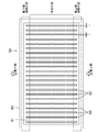
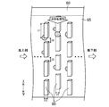
- FIG. 3 is a plan view of the gas-liquid contact module of FIG.
- FIG. 4 is a diagram illustrating pattern 1 of the holding portions near the windward end of the gas-liquid contact plate according to the first embodiment.
- FIG. 5 is a diagram illustrating pattern 2 in the holding portion near the windward end of the gas-liquid contact plate according to the first embodiment.
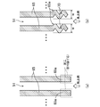
- FIG. 6 is a diagram illustrating pattern 3 in the holding portion near the windward end of the gas-liquid contact plate according to the first embodiment.
- FIG. 7 is a diagram illustrating pattern 4 in the holding portion near the windward end of the gas-liquid contact plate according to the first embodiment.
- FIG. 8 is a diagram illustrating pattern 1 in the holding portion near the center of the gas-liquid contact plate according to the second embodiment.
- FIG. 9 is a diagram illustrating pattern 2 in the holding portion near the center of the gas-liquid contact plate according to the second embodiment.
- FIG. 10 is a diagram illustrating pattern 1 in the holding portion near the leeward side of the gas-liquid contact plate according to the third embodiment.
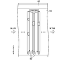
- FIG. 11 is a diagram illustrating pattern 2 in the holding portion near the leeward side of the gas-liquid contact plate according to the third embodiment.
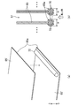
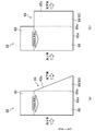
- FIG. 12 is a diagram illustrating pattern 3 in the holding portion near the leeward side of the gas-liquid contact plate according to the third embodiment.
- FIG. 1 shows a configuration of a dehumidifier (10) that includes a gas-liquid contact module (50) according to the present embodiment and performs dehumidification of air.
- the dehumidifier (10) includes a dehumidifier (30), a regenerator (35), a pump (26), a heater (28), and a cooler (27).
- the dehumidifying section (30), the regenerating section (35), the pump (26), the heater (28) and the cooler (27) are connected to each other by a pipe to form a moisture absorbent circuit (20).
- the moisture absorbent circuit (20) is a circuit in which the liquid moisture absorbent as the target liquid circulates.
- the liquid desiccant is a liquid that can absorb moisture (water vapor) in the air.
- an ionic liquid for example, 15 mPaS or more
- an ionic liquid generally having a higher viscosity than the aqueous solution of lithium chloride or the aqueous solution of lithium bromide can be used in addition to the aqueous solution of lithium chloride and the aqueous solution of lithium bromide.
- the dehumidifying section (30) includes a dehumidifying module (31) and a liquid tank (32), and the regenerating section (35) includes a regenerating module (36) and a liquid receiving section (37).
- the dehumidification module (31) and the regeneration module (36) are constituted by the gas-liquid contact module (50) of the present embodiment.
- the gas-liquid contact module (50) includes a header container (60) and a gas-liquid contact plate (65).
- the dehumidifier (10) supplies air to the dehumidifying-side fan that supplies air to the dehumidifying module (31) of the dehumidifying unit (30) and air to the regeneration module (36) of the regeneration unit (35). It also has a playback side fan.
- the moisture absorbent circuit (20) includes a suction side pipe (21), a discharge side pipe (22), a dehumidification side pipe (23), a regeneration side pipe (24), and a liquid return pipe (25).
- One end of the suction pipe (21) is connected to the liquid tank (32) of the dehumidifying section (30), and the other end is connected to the suction port of the pump (26).
- One end of the discharge pipe (22) is connected to the discharge port of the pump (26), and the other end is connected to one end of the dehumidification pipe (23) and one end of the regeneration pipe (24).
- the other end of the dehumidification-side pipe (23) is connected to the header container (60) of the dehumidification module (31).
- a cooler (27) is provided in the dehumidification-side pipe (23).
- the other end of the regeneration-side pipe (24) is connected to a header container (60) of the regeneration module (36).
- the regeneration side pipe (24) is provided with a heater (28).
- the dehumidifying section (30) includes a dehumidifying module (31) and a liquid tank (32).
- the dehumidifying module (31) allows the liquid desiccant supplied from the dehumidifying-side pipe (23) to the header container (60) to flow along the gas-liquid contact plate (65) and flows along the gas-liquid contact plate (65). Contact the liquid desiccant with air.
- the liquid tank (32) is a container-like member disposed below the dehumidification module (31). The liquid tank (32) receives the liquid desiccant flowing down from the dehumidification module (31).
- the regeneration unit (35) includes a regeneration module (36) and a liquid receiving unit (37).
- the regeneration module (36) allows the liquid desiccant supplied from the regeneration side pipe (24) to the header container (60) to flow along the gas-liquid contact plate (65), and flows along the gas-liquid contact plate (65). Contact the liquid desiccant with air.
- the liquid receiving section (37) is a tray-shaped member disposed below the regeneration module (36). The liquid receiving section (37) receives the liquid absorbing material that has flowed down from the regeneration module (36).
- the liquid receiving section (37) is arranged above the liquid tank (32) of the dehumidifying section (30). Therefore, the liquid desiccant in the liquid receiving part (37) flows through the liquid return pipe (25) by gravity, and flows into the liquid tank (32) in the dehumidifying part (30).
- the cooler (27) is a member for cooling the liquid desiccant flowing through the dehumidification-side pipe (23).
- the cooler (27) for example, an evaporator of a refrigerator can be used. In this case, the cooler (27) cools the liquid desiccant with the refrigerant of the refrigerating device.
- the heater (28) is a member for heating the liquid desiccant flowing through the regeneration-side pipe (24).
- the heater (28) for example, a condenser of a refrigerator can be used. In this case, the heater (28) heats the liquid desiccant with the refrigerant of the refrigerating device.
- the dehumidifying device (10) supplies the air dehumidified in the dehumidifying section (30) to, for example, an indoor space, and discharges the air to which moisture has been added in the regenerating section (35) to, for example, an outdoor space.
- the liquid desiccant flowing into the dehumidifying-side pipe (23) is cooled by the cooler (27), then flows into the header container (60) of the dehumidifying module (31), and flows along the gas-liquid contact plate (65). run down.
- the liquid desiccant flowing down along the gas-liquid contact plate (65) absorbs moisture from the air, and the liquid desiccant after absorbing the moisture flows into the liquid tank (32).
- the liquid desiccant flowing into the regeneration side pipe (24) flows into the header container (60) of the regeneration module (36) after being heated by the heater (28), and flows into the gas-liquid contact plate (65). Run down along.
- the liquid desiccant flowing down along the gas-liquid contact plate (65) releases moisture to the air, and the desorbed liquid absorbent flows into the liquid receiving part (37).
- the liquid desiccant flowing into the liquid receiving part (37) flows through the liquid return pipe (25) and flows into the liquid tank (32) of the dehumidifying part (30).
- the gas-liquid contact module (50) includes one header container (60), a plurality of gas-liquid contact plates (65), and a holding unit as shown in FIGS. (70).
- the header container (60) is a rectangular parallelepiped container-shaped member and has a bottom plate (61). As shown in FIG. 3, openings (62) for inserting and fixing the upper ends of the plurality of gas-liquid contact plates (65) are formed at substantially equal intervals in the bottom plate (61).
- the header container (60) stores the liquid desiccant, which is the target liquid, and is located above the gas-liquid contact plate (65) fixed to the bottom plate (61) (specifically, the gas-liquid contact plate (65)). ) Is a gas-liquid supply unit that supplies the liquid desiccant to the upper end).
- the gas-liquid contact plate (65) is a rectangular plate-shaped member arranged so as to extend downward from the position (above) of the header container (60).
- the gas-liquid contact plate (65) has a substantially constant thickness t throughout.
- the material of the gas-liquid contact plate (65) is a material having high wettability and flexibility (for example, nonwoven fabric, hard sponge, etc.).
- the gas-liquid contact plate (65) can prevent the liquid desiccant flowing down along the surface of the gas-liquid contact plate (65) from the header container (60) downward without passing through another member such as a moisture permeable membrane. It is a gas-liquid contact member for making direct contact with air.
- the plurality of gas-liquid contact plates (65) are arranged at regular intervals in the longitudinal direction of the bottom plate (61) of the header container (60) in a posture facing each other. . As described above, the upper ends of the gas-liquid contact plates (65) are inserted into the openings (62) of the bottom plate (61) of the header container (60) and fixed. In the gas-liquid contact module (50), as shown in FIG. 2, an air flow passage (51) is formed between gas-liquid contact plates (65) arranged at regular intervals.
- the flow passage (51) extends along the surface of each gas-liquid contact plate (65).
- the air flows through the flow passage (51) in a direction intersecting with the flow direction of the liquid desiccant (the direction flowing from above to below along the surface of the gas-liquid contact plate (65)), and Direct contact with the agent.
- the holding section (70) allows each gas-liquid contact plate (65) to hold the liquid desiccant.
- the air contacts the liquid desiccant while flowing in a direction intersecting the flow direction of the liquid desiccant. Then, in the gas-liquid contact module (50) having no holding portion (70), the liquid desiccant is influenced by the flow of the air (that is, pushed by the air) and is pushed to the leeward side, Of the surface of the gas-liquid contact plate (65), it tends to be biased toward the leeward end of the plate (65).
- the liquid absorbent when the liquid desiccant flows along the surface of the gas-liquid contact plate (65), the liquid absorbent is deposited on the surface of the gas-liquid contact plate (65) such that the liquid absorbent is laminated on the surface. A film is formed.
- This liquid film preferably has a uniform thickness in view of the performance of the gas-liquid contact module (50).
- the liquid film thickness is uniform because the liquid desiccant is concentrated near the leeward end of the gas-liquid contact plate (65). Instead, the thickness increases near the leeward end of the gas-liquid contact plate (65).
- the width of the flow passage (51) is reduced near the leeward end of the gas-liquid contact plate (65), and the flow velocity (wind velocity) of the air increases accordingly.
- the liquid desiccant which is biased to the vicinity of the leeward end of the surface of the gas-liquid contact plate (65), is affected by the air having the increased flow velocity, and the leeward end of the surface of the gas-liquid contact plate (65) is affected. Away from the vicinity, and further fly downwind (outside the gas-liquid contact module (50)). In the worst case, the scattered liquid desiccant scatters in the room to be dehumidified.
- the holding portion (70) for holding the liquid desiccant on the gas-liquid contact plate (65) by providing the holding portion (70) for holding the liquid desiccant on the gas-liquid contact plate (65), the liquid flowing from above to below is provided. The scattering of the moisture absorbent to the outside of the gas-liquid contact plate (65) due to the influence of the air flow is reduced.
- the holding portion (70) can be provided at various positions on the gas-liquid contact plate (65). In the first embodiment, the holding portion (70) is provided at the windward end of the gas-liquid contact plate (65). The case where it is provided near the portion (65a) will be described.
- Each of the holding portions (70) in FIGS. 4 to 7 is an airflow obstruction mechanism (corresponding to a second obstruction mechanism) that obstructs the flow of air.
- One of the four patterns may be employed as the holding unit (70) and provided on all of the gas-liquid contact plate (65), or each holding unit ( The pattern of 70) may be different.
- FIG. 4A is a perspective view of the holding part (70) of the pattern 1 near the windward end (65a), and FIG. 4B is a perspective view of the holding part (70) of the pattern 1 It is a cross-sectional view near the windward end (65a) of the gas-liquid contact plate (65) attached to 65a).
- the holding portion (70) of the pattern 1 is formed of a member different from the gas-liquid contact plate (65). As shown in FIG. 4A, the holding portion (70) of the pattern 1 extends vertically along the windward end (65a) of the gas-liquid contact plate (65), and has a concave portion (71). ).
- the windward end (65a) of the gas-liquid contact plate (65) is fitted into the recess (71).
- each holding portion (70) of the pattern 1 is determined by the gas-liquid contact plate (65) having the holding portion (70) attached to the windward end (65a).
- they When they are arranged side by side, they preferably have such a width that the holding portions (70) do not contact each other. If the holding portions (70) come into contact with each other, the air flow passage (51) may be completely closed in some cases, and as a result, air will not flow at all through the flow passage (51), and on the contrary, the gas-liquid contact module (50) Does not fulfill functions such as dehumidification and regeneration.
- FIG. 6 illustrates an example in which a portion (70a) of the outer edge of the holding portion (70) located on the air inlet side in the ventilation path (51) protrudes in the direction of the width W, as an example. However, this part (70a) does not have to protrude.
- the holding portion (70) of such a pattern 1 By attaching the holding portion (70) of such a pattern 1 to the windward end (65a) of each gas-liquid contact plate (65), the inflow of air into the flow passage (51) is hindered to some extent. That is, the holding portion (70) functions as a wind shield for the liquid desiccant flowing down the surface of the gas-liquid contact plate (65). Accordingly, it is possible to prevent the liquid moisture absorbent from being pushed by the air and biased to the leeward side.
- FIG. 5A shows a process of attaching the holding part (70) of the pattern 2 near the windward end (65a) to the gas-liquid contact plate (65).
- FIG. 5B is a cross-sectional view of the gas-liquid contact plate (65) in which the holding portion (70) of the pattern 2 is attached to the windward end (65a), near the windward end (65a). is there.
- a gas-liquid contact plate (65) is manufactured by bonding two nonwoven fabrics (65 '), for example.
- a cylindrical member separate from the gas-liquid contact plate (65) is provided between the two nonwoven fabrics (65 ') and near the windward end (65a) of the gas-liquid contact plate (65).
- (72) is placed, and the opposing surfaces of the nonwoven fabrics (65 ') are bonded together so as to cover the columnar member (72) with the two nonwoven fabrics (65'), whereby the holding portion (70) of the pattern 2 is formed.
- a gas-liquid contact plate (65) is generated near the windward end (65a).
- the cylindrical member (72) extends vertically along the windward end (65a) of the gas-liquid contact plate (65), but the material thereof is not particularly limited.
- the gas-liquid contact plates (65) are arranged at equal intervals with the holding portion (70) positioned on the windward side. At this time, it is preferable that the width W of each holding portion (70) of the pattern 2 has a width such that the holding portions (70) do not come into contact with each other, as in the case of the pattern 1.
- Such a holding portion (70) of the pattern 2 inhibits the air from flowing into the flow passage (51) to some extent, similarly to the pattern 1 described above. That is, the holding portion (70) functions as a wind shield for the liquid desiccant flowing down the surface of the gas-liquid contact plate (65). Accordingly, it is possible to prevent the liquid moisture absorbent from being pushed by the air and biased to the leeward side.
- FIGS. 6A and 6B are cross-sectional views of the gas-liquid contact plate (65) near the windward end (65a), and FIG. Before and (b) show after formation.
- the holding portion (70) of the pattern 3 is formed by processing the portion to be the windward end (65 a) of the gas-liquid contact plate (65) as shown in FIG. Is formed on the windward end (65a) by crushing until the cross section becomes approximately semicircular.
- the holding portion (70) of the pattern 3 extends vertically along the windward end (65a) of the gas-liquid contact plate (65). Since the holding portion (70) of the pattern 3 is formed by processing a part of the gas-liquid contact plate (65), its material is the same as that of the gas-liquid contact plate (65).
- the width W of the holding portion (70) of the pattern 3 is the same as that of the patterns 1 and 2, and the gas-liquid having the holding portion (70) formed at the windward end (65a).
- the contact plates (70) it is preferable that the contact plates (70) have such a width that the holding portions (70) do not contact each other.
- Such a holding portion (70) of the pattern 3 prevents air from flowing into the flow passage (51) to some extent, similarly to the patterns 1 and 2. That is, the holding portion (70) functions as a wind shield for the liquid desiccant flowing down the surface of the gas-liquid contact plate (65). Accordingly, it is possible to prevent the liquid moisture absorbent from being pushed by the air and biased to the leeward side.
- FIG. 7 (a) and 7 (b) are cross-sectional views of the gas-liquid contact plate (65) near the windward end (65a), and FIG. 7 (a) shows the formation of the holding portion (70) of the pattern 4. Before and (b) show after formation.
- the holding portion (70) of the pattern 4 is formed by processing the portion to be the windward end (65 a) of the gas-liquid contact plate (65) as shown in FIG. It is formed by folding the bellows.
- the holding portion (70) of the pattern 4 extends vertically along the windward end (65a) of the gas-liquid contact plate (65). Since the holding portion (70) of the pattern 4 is formed by processing a part of the gas-liquid contact plate (65), its material is the same as that of the gas-liquid contact plate (65).
- the width W of the holding portion (70) of the pattern 4 is the same as that of the above-mentioned patterns 1 to 3, and the gas-liquid having the holding portion (70) formed at the windward end (65a).
- the contact plates (70) it is preferable that the contact plates (70) have such a width that the holding portions (70) do not contact each other.
- the holding portion (70) of the pattern 4 By the holding portion (70) of the pattern 4, the inflow of air into the flow passage (51) is hindered to some extent, similarly to the patterns 1 to 3 described above. That is, the holding portion (70) functions as a wind shield for the liquid desiccant flowing down the surface of the gas-liquid contact plate (65). Accordingly, it is possible to prevent the liquid moisture absorbent from being pushed by the air and biased to the leeward side.
- the gas-liquid contact module (50) of the first embodiment is disposed so as to extend from above to below, and causes the liquid desiccant flowing down from above to air to flow in a direction intersecting the flow direction of the liquid desiccant.
- Gas-liquid contact plate (65) to make direct contact with the water
- header container (60) for supplying liquid desiccant on top of gas-liquid contact plate (65), and liquid desiccant held in gas-liquid contact plate (65)
- a holding section (70) A holding section (70).
- the liquid desiccant flowing down from above is held by the holding section (70). Therefore, under the influence of the air flowing in a direction intersecting with the flow direction of the liquid desiccant, the liquid desiccant flows from the gas-liquid contact plate (65) to the gas-liquid contact plate (65) from the downstream side in the air flow direction. Can be suppressed from scattering outside.
- the gas-liquid contact plate (65) is a plate-like member extending downward from above, and the air flows along the surface of the gas-liquid contact plate (65) so that the liquid desiccant is formed. Flows in a direction that intersects the flow direction of
- the air flows along the surface of the gas-liquid contact plate (65), which is a plate-like member, in a direction intersecting with the flow direction of the liquid desiccant.
- the holding unit (70) is provided on the gas-liquid contact plate (65).
- the liquid desiccant is held by the gas-liquid contact plate (65) by the holding portion (70) provided on the gas-liquid contact plate (65).
- the holding part (70) is located at the windward end (65a) located on the upstream side in the air flow direction among the ends of the gas-liquid contact plate (65). Is a second inhibition mechanism that inhibits the flow of blood.
- the air flow in the direction intersecting with the flow direction of the liquid desiccant is impeded by the holding portion (70) located at the windward end (65a) of the gas-liquid contact plate (65). That is, the holding portion (70) plays a role of a wind shield for the liquid desiccant. Therefore, the target liquid that flows downward from above is less likely to be affected by the flow of air, so that the liquid absorbent is less likely to flow toward the downstream side in the air flow direction. Even if the liquid desiccant flows toward the downstream side of the gas-liquid contact plate (65) in the flow direction of the air under the influence of air, the liquid desiccant flows out of the gas-liquid contact plate (65). Scattering is also suppressed.
- Embodiment 2 In the second embodiment, unlike the first embodiment, the holding unit is provided near the center of the gas-liquid contact plate (65).
- the components other than the holding unit are the same as those in the first embodiment.
- the components other than the holding unit will be denoted by the same reference numerals as those in the first embodiment, and the holding unit will be denoted by “80”. Only the configuration of the unit (80) will be described.
- FIG. 8 and 9 show two examples of the pattern of the holding portion (80) provided near the center excluding the vicinity of the leeward end and the vicinity of the leeward end of the gas-liquid contact plate (65).
- Each of the holding portions (80) in FIG. 8 and FIG. 9 prevents the liquid desiccant, which normally would flow from above to below, from flowing toward the leeward side under the influence of the air flow.
- An inhibition mechanism (corresponding to a second inhibition mechanism) is formed on the surface of the gas-liquid contact plate (65).
- one of the two patterns may be adopted as the holding unit (80) and provided on the entire gas-liquid contact plate (65), or each holding unit ( The pattern of 80) may be different.
- FIG. 8 is an enlarged view mainly showing a part of the surface of the gas-liquid contact plate (65) on which the holding portion (80) of the pattern 1 near the center is formed.
- a groove is formed on the surface of the gas-liquid contact plate (65), and the groove is a holding portion (80) of the pattern 1.
- the holding portion (80), which is a groove extends downward from the upper side (that is, the header container (60)) side on the surface of the gas-liquid contact plate (65), and extends from the windward side to the leeward side.
- a plurality of rows are formed at intervals. In FIG. 8, the width s of each groove is constant.
- the holding portion (80) which is a groove, is provided on a portion of the surface of the gas-liquid contact plate (65) where the liquid desiccant flows down (that is, a storage portion of the liquid desiccant which is an inner wall of the header container (60)).
- a plurality of them are formed correspondingly.
- the holding portion (80), which is a groove is formed on both surfaces of the gas-liquid contact plate (65), which is a plate-like member.
- the holding portion (80), which is a groove is formed on any of the surfaces of the gas-liquid contact plate (65) opposed to each other via the flow passage (51).
- the liquid desiccant flowing down the surface of the gas-liquid contact plate (65) from above the plate (65) is held in a state of being dispersed to some extent by the plurality of holding portions (80) which are grooves. .
- the liquid desiccant is hardly affected by the air because it is held in the holding portion (80) which is a groove. Therefore, since the liquid desiccant is prevented from being pushed by the air and biased to the leeward side, the liquid desiccant is unlikely to collect near the leeward end (65a) of the surface of the gas-liquid contact plate (65). Become.
- FIG. 9 is an enlarged view mainly showing a part of the surface of the gas-liquid contact plate (65) on which the holding portion (80) of the pattern 2 near the center is formed.
- a protruding portion protruding portion protruding outward from the surface is formed, and this protruding portion is a holding portion (80) of the pattern 2.
- the holding portion (80) which is a protruding portion, extends a predetermined length U1 downward from the upper side (that is, the header container (60)) side on the surface of the gas-liquid contact plate (65), and is adjacent in the vertical direction.
- the holding portions (80) are spaced at a fixed interval U2.
- the plurality of rows of the holding portions (80) are formed at predetermined intervals from the windward side to the leeward side.
- the width U3 of each projection along the air flow direction is constant. Further, in FIG. 9, in the adjacent rows, the intervals between the holding units (80) are alternately positioned.
- the holding portion (80) of the pattern 2 is a portion of the surface of the gas-liquid contact plate (65) through which the liquid desiccant flows down (that is, the header container (60)). It is preferable that a plurality of the liquid absorbents are formed so as to correspond to the inner wall of the liquid desiccant.
- the holding portion (80) is preferably formed on both surfaces of the gas-liquid contact plate (65) which is a plate-like member.
- the holding portion (80), which is a protruding portion is formed on any of the surfaces of the gas-liquid contact plate (65) opposed to each other via the flow passage (51).
- the holding portion (80), which is a protruding portion protrudes in a direction intersecting with the air flow direction (in a direction that obstructs air flow).
- the liquid desiccant flowing down from above the gas-liquid contact plate (65) on the surface of the plate (65) is prevented from flowing between the holding portions (80), which are protrusions, and the wind of the holding portion (80). It is held on the upper side.
- the liquid desiccant is held on the windward side of the holding part (80), even if air passes through the flow passage (51) from the windward side to the leeward side, the liquid desiccant is retained on the holding part (80). ) Blocks the flow to the leeward side. Therefore, the liquid desiccant is less susceptible to the influence of the air, and is prevented from being pushed to the leeward side by the air.
- FIG. 8 illustrates the case where the holding portion (80) is a groove
- FIG. 9 illustrates the case where the holding portion (80) is a protruding portion
- the holding portion (80) protrudes in the arrangement state of FIG.
- the holding portion (80) may be formed by a groove in the arrangement shown in FIG.
- the gas-liquid contact module (50) is disposed so as to extend from above to below, and causes the liquid desiccant flowing down from above to air to flow in a direction intersecting the flow direction of the liquid desiccant.
- Gas-liquid contact plate (65) to make direct contact with the water, header container (60) for supplying liquid desiccant on top of gas-liquid contact plate (65), and liquid desiccant held in gas-liquid contact plate (65)
- a holding unit (80) A holding unit (80).
- the liquid desiccant flowing down from above is held by the holding section (80). Therefore, under the influence of air flowing in a direction intersecting with the flow direction of the liquid desiccant, the liquid desiccant is transferred from the gas-liquid contact plate (65) to the gas-liquid contact plate (65) from the downstream side in the air flow direction. ) Can be prevented from scattering outside.
- the gas-liquid contact plate (65) is a plate-like member extending downward from above, and the air flows along the surface of the gas-liquid contact plate (65) so that the liquid desiccant is formed. Flows in a direction that intersects the flow direction of
- the air flows along the surface of the gas-liquid contact plate (65), which is a plate-like member, in a direction intersecting with the flow direction of the liquid desiccant.
- the holding unit (80) is provided on the gas-liquid contact plate (65).
- the liquid desiccant is held by the gas-liquid contact plate (65) by the holding portion (80) provided on the gas-liquid contact plate (65).
- the holding portion (80) is formed on the surface of the gas-liquid contact plate (65) as a first inhibition mechanism that inhibits the flow of the liquid desiccant under the influence of the flow of air. ing.
- the liquid desiccant flowing down from above is held by the holding portion (80), which is the first inhibition mechanism that inhibits the liquid desiccant from flowing under the influence of the air flow. Therefore, even if the liquid desiccant is pushed to the leeward side under the influence of the air flow, it is difficult for the liquid desiccant to flow downstream of the gas-liquid contact plate (65) in the air flow direction. Even if the liquid desiccant flows slightly to the downstream side in the air flow direction in the gas-liquid contact plate (65) under the influence of the air, the liquid desiccant flows in the air-liquid contact plate (65). Of the plate (65) from the downstream side in the flow direction can be suppressed.
- the holding portion (80), which is the first inhibiting mechanism, is a groove formed on the surface of the gas-liquid contact plate (65).
- the liquid desiccant flowing down from above is retained by the first inhibition mechanism, which is a groove formed on the surface of the gas-liquid contact plate (65). Therefore, even if the air is flowing through the ventilation path (51), the liquid desiccant is less likely to flow downstream of the gas-liquid contact plate (65) in the air flow direction.
- the holding portion (80), which is the first inhibiting mechanism, is a protruding portion that protrudes outward from the surface of the gas-liquid contact plate (65).
- the liquid desiccant flowing down from above is held by the first inhibition mechanism, which is a protrusion formed on the surface of the gas-liquid contact plate (65). Therefore, even if the liquid desiccant is pushed by the air flow in the ventilation path (51), the liquid desiccant is blocked by the first obstruction mechanism, which is a protruding portion, and further downstream in the air flow direction in the gas-liquid contact plate (65). It is difficult to flow to
- Embodiment 3 unlike the first and second embodiments, the holding unit is provided near the leeward end of the gas-liquid contact plate (65).
- the components other than the holding unit are the same as those in the first embodiment.
- the components other than the holding unit will be denoted by the same reference numerals as those in the first embodiment, and the holding unit will be denoted by reference numeral “90”. Only the configuration of the unit (90) will be described.
- 10 to 12 are provided near the leeward end (65c) (downstream end) located on the leeward side, which is the downstream side in the air flow direction, of the end of the gas-liquid contact plate (65).
- 8 shows three examples of patterns of the holding unit (90).
- any of the holding portions (90) in FIGS. 10 to 12 even if the liquid desiccant, which normally should flow from above to below, is pushed downwind by the influence of the air flow and flows.
- This is a scattering suppression mechanism for suppressing the liquid desiccant from scattering from the leeward end (65c) of the gas-liquid contact plate (65) to the outside of the plate (65) which is further downwind.
- One of the three patterns may be employed as the holding unit (90) and provided on all of the gas-liquid contact plate (65), or each holding unit ( The pattern of 90) may be different.
- FIG. 10A is a perspective view of the holding portion (90) of the pattern 1 near the leeward end (65c), and FIG. 10B is a diagram illustrating that the holding portion (90) of the pattern 1 is the leeward end ( It is a cross-sectional view near the leeward end (65c) of the gas-liquid contact plate (65) attached to 65c).
- the holding portion (90) of the pattern 1 is formed of a member different from the gas-liquid contact plate (65).
- the holding portion (70) of the pattern 1 extends vertically along the leeward end (65c) of the gas-liquid contact plate (65) and has a concave portion (91). ).
- the leeward end (65c) of the gas-liquid contact plate (65) is fitted into the recess (91).
- the lower part of the concave portion (91) is connected to the header container (60).
- the width V of the holding portion (90) of the pattern 1 is such that the gas-liquid contact plate (65) having the holding portion (90) attached to the leeward end (65c) is arranged.
- the holding portions (90) have such a width that they do not contact each other. If the holding portions (90) come into contact with each other, the air flow passage (51) may be completely closed in some cases, and as a result, air will not flow at all through the flow passage (51), and on the contrary, the gas-liquid contact module (50) Does not fulfill functions such as dehumidification and regeneration.
- the holding portion (90) of such a pattern 1 Since the holding portion (90) of such a pattern 1 is attached to the leeward end (65c) of each gas-liquid contact plate (65), it flows downward from the position (upper) of the header container (60).
- the liquid desiccant flows to the leeward side under the influence of the flow of air passing through the ventilation path (51), the liquid desiccant is received by the concave portion (91) of the holding portion (90), It is collected and held near the leeward end (65c) of the gas-liquid contact plate (65). The collected liquid desiccant is then sent to the header container (60).
- the holding unit (90) has a function as a collection unit that collects the liquid desiccant that has flowed to the leeward side under the influence of the air flow. This can prevent the liquid desiccant from scattering from the leeward end (65c) of the gas-liquid contact plate (65) to the outside of the leeward side of the plate (65).
- FIG. 14 is a simplified view of the surface and the like of the gas-liquid contact plate (65) when formed in (1).
- the gas-liquid contact plate (65) extended to the leeward side has a first portion (68) through which the liquid desiccant flows down, and a first portion (68).
- the first portion (68) is a portion corresponding to the header container (60), more specifically, a portion corresponding to the storage portion of the liquid desiccant, which is the inner wall of the header container (60).
- the second portion (69) does not correspond to the portion.
- the second portion (69) is formed continuously with the first portion (68).
- the liquid desiccant flowing down from the header container (60) is affected by the flow of air passing through the ventilation path (51) and flows on the surface of the first portion (68). It flows downward while being pushed downwind. That is, the liquid desiccant flows down obliquely downward. Even if the liquid desiccant reaches the leeward end (68a) of the first portion (68), the leeward end (68a) of the first portion (68) has a holding portion (90) as the holding portion (90). Since the two portions (69) are continuously present, the liquid desiccant reaching the leeward end (68a) continues to flow on the surface of the second portion (69).
- the second portion (69) extends to the leeward side by a sufficient length, the liquid desiccant flowing on the surface of the second portion (69) becomes leeward of the gas-liquid contact plate (65).
- the second portion (69) corresponding to the end does not reach the leeward end (65c), but eventually reaches the lower end (65d) of the gas-liquid contact plate (65). Therefore, it can be said that the liquid desiccant is temporarily held in the holding part (90) which is the second part (69), and the liquid desiccant is held on the leeward end (65c) of the gas-liquid contact plate (65). It is possible to prevent the plate (65) from being further leeward from being scattered outside the plate (65).
- FIG. 11A illustrates a case where the shape of the second portion (69) is approximately triangular.
- FIG. 11B illustrates a case where the shape of the second portion (69) is rectangular.
- the shape of the second portion (69) illustrated in FIG. 11 (a) has an approximately triangular shape in which the area increases toward the bottom in consideration of the fact that the liquid desiccant flows down obliquely under the influence of the flow of air. It has a shape.
- the extent to which the second portion (69) is extended to the leeward side is determined in consideration of the wind speed of the air, the amount of the liquid desiccant to be dripped, and the like, and the leeward end of the gas-liquid contact plate (65). It is preferable to set appropriately so as to satisfy the condition that the liquid desiccant does not reach (65c).
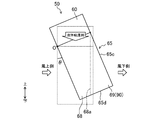
- FIG. 12 shows a case where the holding portion (90) of the pattern 3 near the leeward end is formed on the leeward side of the gas-liquid contact plate (65) by the inclination of the gas-liquid contact module (50) itself. It is the figure which simplified and represented the surface etc. of the liquid contact plate (65).
- the leeward side portion of the gas-liquid contact module (50) is moved upward with the center O being the most leeward side of the contact portion between the header container (60) and the gas-liquid contact plate (65).
- the module (50) itself is inclined at a predetermined angle ⁇ so as to lift the module.
- the gas-liquid contact plate (65) is provided with the first portion (68) through which the liquid desiccant flows down without intentionally extending the liquid contact plate (65) to the leeward side as in the pattern 2, and the first portion (68).
- a second portion (69) extending more leeward (downstream in the air flow direction) than (68). Of these, the second portion (69) also serves as the holding portion (90).
- the first portion (68) is a portion where the liquid desiccant flows down from the header container (60) if there is no influence of the air flow
- the second portion (69) is a portion where the liquid moisture is not affected by the air flow. If there is no liquid absorbent, the liquid absorbent from the header container (60) does not flow down.
- the second portion (69) is formed continuously with the first portion (68).
- the liquid desiccant flowing down from the header container (60) is affected by the flow of air passing through the ventilation path (51) and flows on the surface of the first portion (68). It flows down diagonally downward while being pushed downwind. Even if the liquid desiccant reaches the leeward end (68a) of the first portion (68), the leeward end (68a) of the first portion (68) has a holding portion (90) as the holding portion (90). Since the two portions (69) are continuously present, the liquid desiccant reaching the leeward end (68a) continues to flow on the surface of the second portion (69).
- the liquid desiccant flowing on the surface of the second portion (69) is gas-liquid It does not reach the leeward end (65c) of the second portion (69) corresponding to the leeward end of the contact plate (65), but eventually reaches the lower end (65d) of the gas-liquid contact plate (65). I do. Therefore, it can be said that the liquid desiccant is temporarily held in the holding part (90) which is the second part (69), and the liquid desiccant is held on the leeward end (65c) of the gas-liquid contact plate (65). It is possible to prevent the plate (65) from being further leeward from being scattered outside the plate (65).
- the inclination angle ⁇ of the gas-liquid contact module (50) is determined in consideration of the wind speed of the air, the amount of the liquid absorbent to be dripped, and the like. It is preferable that the temperature is appropriately set so as to satisfy the condition that the liquid desiccant does not reach the liquid desiccant.
- the gas-liquid contact module (50) is disposed so as to extend from above to below, and causes the liquid desiccant flowing down from above to air to flow in a direction intersecting the flow direction of the liquid desiccant.
- Gas-liquid contact plate (65) to make direct contact with the water
- header container (60) for supplying liquid desiccant on top of gas-liquid contact plate (65), and liquid desiccant held in gas-liquid contact plate (65) Holding part (90).
- the liquid desiccant flowing down from above is held by the holding section (90). Therefore, under the influence of air flowing in a direction intersecting with the flow direction of the liquid desiccant, the liquid desiccant is transferred from the gas-liquid contact plate (65) to the gas-liquid contact plate (65) from the downstream side in the air flow direction. ) Can be prevented from scattering outside.
- the gas-liquid contact plate (65) is a plate-like member extending downward from above, and the air flows along the surface of the gas-liquid contact plate (65) to form a liquid desiccant. Flows in a direction that intersects the flow direction of
- the air flows along the surface of the gas-liquid contact plate (65), which is a plate-like member, in a direction intersecting with the flow direction of the liquid desiccant.
- the holding unit (90) is provided on the gas-liquid contact plate (65).
- the liquid desiccant is held by the gas-liquid contact plate (65) by the holding portion (90) provided on the gas-liquid contact plate (65).
- the header container (60) supplies the liquid desiccant to the upper end of the gas-liquid contact plate (65), and the gas-liquid contact plate (65) supplies the liquid desiccant.
- the second portion (69) is provided with a holding portion (90). ).
- the liquid desiccant is held in the second portion (69) of the gas-liquid contact plate (65) that extends downstream of the first portion (68) in the air flow direction. Therefore, even if the liquid desiccant flows from the first part (68) to the second part (69) under the influence of air, the liquid desiccant does not flow through the gas-liquid contact plate (65). It becomes difficult to scatter from the downstream side in the direction to the outside of the gas-liquid contact plate (65).
- the leeward end (65c) located on the downstream side in the air flow direction flows down from the header container (60).
- the collecting part for collecting the liquid desiccant is located as the holding part (90).
- the holding unit (90) as the collecting unit As the collecting unit Thereby, it is collected and held near the leeward end (65c) of the gas-liquid contact plate (65). Therefore, the liquid desiccant is less likely to scatter outside the gas-liquid contact plate (65).
- the holding unit is not provided near the windward end (65a), near the center, or near the leeward end (65c) of the gas-liquid contact plate (65) as in the first to third embodiments.
- the gas-liquid contact plate (65) itself may be used. That is, the gas-liquid contact plate (65) may also serve as a holding portion by having a structure in which the liquid desiccant flows inside.
- the surface of the gas-liquid contact plate (65) may be a through hole passing through the surface instead of the "groove”. Even with the “through hole”, the same effect as in the case of the “groove” can be obtained.
- the present invention is useful as a gas-liquid contact module.
- Gas-liquid contact module 60 Header container (gas-liquid supply section) 65 Gas-liquid contact plate (gas-liquid contact member) 65a Windward end (upstream end) 65c Downwind end (downstream end) 68 First part 69 Second part 70,80,90 Holder
Landscapes
- Chemical & Material Sciences (AREA)
- Engineering & Computer Science (AREA)
- Chemical Kinetics & Catalysis (AREA)
- Combustion & Propulsion (AREA)
- Organic Chemistry (AREA)
- Thermal Sciences (AREA)
- Physics & Mathematics (AREA)
- Mechanical Engineering (AREA)
- General Engineering & Computer Science (AREA)
- Analytical Chemistry (AREA)
- General Chemical & Material Sciences (AREA)
- Oil, Petroleum & Natural Gas (AREA)
- Drying Of Gases (AREA)
- Central Air Conditioning (AREA)
- Physical Or Chemical Processes And Apparatus (AREA)
Abstract
気液接触モジュール(50)は、上方から下方へ延びるように配置され、上方から下方に向かって流れ落ちる液体吸湿剤を、液体吸湿剤の流れ方向と交差する方向に流れる空気と直接接触させる気液接触プレート(65)と、気液接触プレート(65)の上部に液体吸湿剤を供給する気液供給部(60)と、気液接触プレート(65)に液体吸湿剤を保持させる保持部(70,80,90)とを備える。
Description
本開示は、気液接触モジュールに関するものである。
従来より、対象液体を空気と接触させる気液接触モジュールが知られている。そのモジュールとしては、例えば特許文献1に開示されているように、対象液体(熱媒)が循環する管の下部に、複数の起立した気液接触部材(プレートフィン)が互いに所定間隔をあけて取り付けられた構成を有するものがある。気液接触部材(プレートフィン)同士の間を空気が通過し、管からは対象液体(熱媒)が気液接触部材(プレートフィン)の表面を伝って上方から下方へと流れ落ちる。
上記特許文献1では、空気の流れ方向と対象液体(熱媒)の流れ落ちる方向とが交差している。それ故、対象液体(熱媒)は、管から真下にではなく、空気の流れの影響を受けて空気の流れ方向下流側寄りに流れていく。すると、本来であれば対象液体(熱媒)が気液接触部材(プレートフィン)の表面を真下に流れ落ちることで当該気液接触部材(プレートフィン)の表面に均等に形成されるはずの熱媒の液膜が、気液接触部材(プレートフィン)の空気の流れ方向下流側端部付近にて厚くなる。すると、対象液体(熱媒)は、更なる空気の流れの影響を受けて当該空気の流れ方向下流側端部から気液接触部材(プレートフィン)の外部へと飛散してしまう。
本開示の目的は、対象液体が気液接触部材の外部に飛散する現象の発生を抑制することである。
本開示の第1の態様は、上方から下方へ延びるように配置され、上方から下方に向かって流れ落ちる対象液体を、該対象液体の流れ方向と交差する方向に流れる空気と直接接触させる気液接触部材(65)と、上記気液接触部材(65)の上部に上記対象液体を供給する気液供給部(60)と、上記気液接触部材(65)に上記対象液体を保持させる保持部(70,80,90)とを備えることを特徴とする気液接触モジュールである。
ここでは、上方から下方に向かって流れ落ちる対象液体は、保持部(70,80,90)によって保持される。そのため、この対象液体の流れ方向に対して交差する方向に流れる空気の影響を受けて、対象液体が気液接触部材(65)における空気の流れ方向下流側から当該気液接触部材(65)の外部へと飛散してしまうことを抑制することができる。
本開示の第2の態様は、第1の態様において、上記気液接触部材(65)は、上方から下方に延びる板状部材であって、空気は、上記気液接触部材(65)の表面に沿うようにして、上記対象液体の流れ方向と交差する方向に流れるものである。
ここでは、空気は、板状部材である気液接触部材(65)の表面に沿って、対象液体の流れ方向とは交差する方向に流れていく。
本開示の第3の態様は、第2の態様において、保持部(70,80,90)は、上記気液接触部材(65)に設けられている。
ここでは、気液接触部材(65)に設けられた保持部(70,80,90)によって、対象液体は気液接触部材(65)に保持される。
本開示の第4の態様は、第3の態様において、上記気液供給部(60)は、上記気液接触部材(65)の上端部に上記対象液体を供給し、上記気液接触部材(65)は、上記対象液体が流れ落ちる第1部分(68)と、該第1部分よりも空気の流れ方向下流側に延びる第2部分(69)とを有し、上記第2部分(69)は、上記保持部(90)を兼ねている。
ここでは、気液接触部材(65)のうち、第1部分(68)よりも空気の流れ方向下流側に延びる第2部分(69)に、対象液体が保持される。そのため、空気の影響を受けて、対象液体がたとえ第1部分(68)から第2部分(69)に流れたとしても、当該対象液体は、気液接触部材(65)における空気の流れ方向下流側から当該気液接触部材(65)の外部へと飛散しにくくなる。
本開示の第5の態様は、第3の態様または第4の態様において、上記保持部(80)は、上記気液接触部材(65)の表面に、空気の流れの影響を受けて上記対象液体が流れるのを阻害する第1阻害機構として形成されている。
これにより、上方から下方に向かって流れ落ちる対象液体は、空気の流れの影響を受けて対象液体が流れるのを阻害する第1阻害機構である保持部(80)によって保持される。そのため、対象液体は、空気の流れに押されても、気液接触部材(65)における空気の流れ方向下流側へは流れにくくなる。
本開示の第6の態様は、第5の態様において、上記第1阻害機構は、上記気液接触部材(65)の表面に形成された溝である。
ここでは、上方から下方に向かって流れ落ちる対象液体は、気液接触部材(65)の表面に形成された溝である第1阻害機構に保持される。そのため、対象液体は、空気が流れていても、気液接触部材(65)における空気の流れ方向下流側へは流れにくくなる。
本開示の第7の態様は、第5の態様から第6の態様のいずれか1つにおいて、上記第1阻害機構は、上記気液接触部材(65)の表面において該表面から外方に突出する突出部である。
ここでは、上方から下方に向かって流れ落ちる対象液体は、気液接触部材(65)の表面に形成された突出部である第1阻害機構に保持される。そのため、対象液体は、空気の流れに押されても、突出部である第1阻害機構によってせき止められ、それ以上気液接触部材(65)における空気の流れ方向下流側へは流れにくくなる。
本開示の第8の態様は、第2の態様から第7の態様のいずれか1つにおいて、上記気液接触部材(65)の端部のうち、空気の流れ方向下流側に位置する下流側端部(65c)には、上記気液供給部(60)から流れ落ちた上記対象液体を収集する収集部が、上記保持部(90)として位置している。
ここでは、上方から下方に流れ落ちる対象液体が、空気の影響を受けて気液接触部材(65)の下流側端部(65c)に流れてきたとしても、収集部である保持部(90)により気液接触部材(65)の下流側端部(65c)付近に収集され保持される。従って、対象液体は、気液接触部材(65)の外部へと飛散しにくくなる。
本開示の第9の態様は、第2の態様から第8の態様のいずれか1つにおいて、上記保持部(70)は、上記気液接触部材(65)の端部のうち、空気の流れ方向上流側に位置する上流側端部(65a)に位置し、該空気の流れを阻害する第2阻害機構である。
ここでは、対象液体の流れ方向と交差する方向への空気の流れが、気液接触部材(65)の上流側端部(65a)に位置する第2阻害機構である保持部(70)によって阻害される。つまり、保持部(70)は、対象液体にとって風除けの役割を担う。それ故、上方から下方へと流れ落ちる対象液体は空気の流れの影響を受けにくくなるため、対象液体が空気の流れ方向下流側寄りに流れることは低減される。
本開示の第10の態様は、第2の態様から第9の態様のいずれか1つにおいて、上記気液接触部材(65)は、上記対象液体が内部を流れる構造を有することにより、上記保持部(70,80,90)を兼ねている。
これにより、気液接触部材(65)とは別部材での保持部を設けずとも、液体吸湿剤が気液接触部材(65)外部に飛散することを抑制できる。
≪実施形態1≫
<除湿装置の構成>
図1は、本実施形態に係る気液接触モジュール(50)を備えて空気の除湿を行う除湿装置(10)の構成を表す。
<除湿装置の構成>
図1は、本実施形態に係る気液接触モジュール(50)を備えて空気の除湿を行う除湿装置(10)の構成を表す。
図1に示すように、除湿装置(10)は、除湿部(30)、再生部(35)、ポンプ(26)、加熱器(28)及び冷却器(27)を備える。除湿部(30)、再生部(35)、ポンプ(26)、加熱器(28)及び冷却器(27)は、配管によって互いに接続されて吸湿剤回路(20)を形成する。
吸湿剤回路(20)は、対象液体である液体吸湿剤が循環する回路である。液体吸湿剤は、空気中の水分(水蒸気)を吸収できる液体である。液体吸湿剤としては、塩化リチウム水溶液、臭化リチウム水溶液の他、一般的に塩化リチウム水溶液や臭化リチウム水溶液よりも粘度の高いイオン液体(例えば15mPaS以上)、を利用することもできる。
除湿部(30)は除湿モジュール(31)と液槽(32)とを備え、再生部(35)は再生モジュール(36)と液受部(37)とを備える。除湿モジュール(31)及び再生モジュール(36)は、本実施形態の気液接触モジュール(50)によって構成される。気液接触モジュール(50)は、ヘッダ容器(60)と気液接触プレート(65)とを備える。
気液接触モジュール(50)の詳細な構成については、後述する。
また、図示しないが、除湿装置(10)は、除湿部(30)の除湿モジュール(31)へ空気を供給する除湿側ファン、及び、再生部(35)の再生モジュール(36)へ空気を供給する再生側ファンも備える。
-吸湿剤回路-
吸湿剤回路(20)は、吸入側配管(21)、吐出側配管(22)、除湿側配管(23)、再生側配管(24)、及び、液戻し配管(25)を備える。
吸湿剤回路(20)は、吸入側配管(21)、吐出側配管(22)、除湿側配管(23)、再生側配管(24)、及び、液戻し配管(25)を備える。
吸入側配管(21)は、一端が除湿部(30)の液槽(32)に接続され、他端がポンプ(26)の吸入口に接続されている。吐出側配管(22)は、一端がポンプ(26)の吐出口に接続され、他端が除湿側配管(23)の一端側と再生側配管(24)の一端側とに接続されている。除湿側配管(23)の他端は、除湿モジュール(31)のヘッダ容器(60)に接続されている。除湿側配管(23)には、冷却器(27)が設けられている。再生側配管(24)の他端は、再生モジュール(36)のヘッダ容器(60)に接続されている。再生側配管(24)には、加熱器(28)が設けられている。
-除湿部-
除湿部(30)は、除湿モジュール(31)と液槽(32)とを備える。除湿モジュール(31)は、除湿側配管(23)からヘッダ容器(60)へ供給された液体吸湿剤を気液接触プレート(65)に沿って流し、気液接触プレート(65)に沿って流れる液体吸湿剤を空気と接触させる。液槽(32)は、除湿モジュール(31)の下方に配置された容器状の部材である。この液槽(32)は、除湿モジュール(31)から流れ落ちた液体吸湿剤を受け止める。
除湿部(30)は、除湿モジュール(31)と液槽(32)とを備える。除湿モジュール(31)は、除湿側配管(23)からヘッダ容器(60)へ供給された液体吸湿剤を気液接触プレート(65)に沿って流し、気液接触プレート(65)に沿って流れる液体吸湿剤を空気と接触させる。液槽(32)は、除湿モジュール(31)の下方に配置された容器状の部材である。この液槽(32)は、除湿モジュール(31)から流れ落ちた液体吸湿剤を受け止める。
-再生部-
再生部(35)は、再生モジュール(36)と液受部(37)とを備える。再生モジュール(36)は、再生側配管(24)からヘッダ容器(60)へ供給された液体吸湿剤を気液接触プレート(65)に沿って流し、気液接触プレート(65)に沿って流れる液体吸湿剤を空気と接触させる。液受部(37)は、再生モジュール(36)の下方に配置されたトレイ状の部材である。この液受部(37)は、再生モジュール(36)から流れ落ちた液体吸収材を受け止める。
再生部(35)は、再生モジュール(36)と液受部(37)とを備える。再生モジュール(36)は、再生側配管(24)からヘッダ容器(60)へ供給された液体吸湿剤を気液接触プレート(65)に沿って流し、気液接触プレート(65)に沿って流れる液体吸湿剤を空気と接触させる。液受部(37)は、再生モジュール(36)の下方に配置されたトレイ状の部材である。この液受部(37)は、再生モジュール(36)から流れ落ちた液体吸収材を受け止める。
液受部(37)は、除湿部(30)の液槽(32)よりも上方に配置される。このため、液受部(37)の液体吸湿剤は、重力によって液戻し配管(25)を流れ、除湿部(30)の液槽(32)に流入する。
-冷却器、加熱器-
冷却器(27)は、除湿側配管(23)を流れる液体吸湿剤を冷却するための部材である。冷却器(27)としては、例えば冷凍装置の蒸発器を用いることができる。この場合、冷却器(27)は、冷凍装置の冷媒によって液体吸湿剤を冷却する。
冷却器(27)は、除湿側配管(23)を流れる液体吸湿剤を冷却するための部材である。冷却器(27)としては、例えば冷凍装置の蒸発器を用いることができる。この場合、冷却器(27)は、冷凍装置の冷媒によって液体吸湿剤を冷却する。
加熱器(28)は、再生側配管(24)を流れる液体吸湿剤を加熱するための部材である。加熱器(28)としては、例えば冷凍装置の凝縮器を用いることができる。この場合、加熱器(28)は、冷凍装置の冷媒によって液体吸湿剤を加熱する。
<除湿装置の運転動作>
ポンプ(26)を駆動すると、吸湿剤回路(20)において液体吸湿剤が循環する。除湿装置(10)は、除湿部(30)において除湿された空気を例えば室内空間へ供給し、再生部(35)において水分を付与された空気を例えば屋外空間へ排出する。
ポンプ(26)を駆動すると、吸湿剤回路(20)において液体吸湿剤が循環する。除湿装置(10)は、除湿部(30)において除湿された空気を例えば室内空間へ供給し、再生部(35)において水分を付与された空気を例えば屋外空間へ排出する。
吸湿剤回路(20)において、ポンプ(26)から吐出された液体吸湿剤は、その一部が除湿側配管(23)に流入し、残りが再生側配管(24)に流入する。
除湿側配管(23)に流入した液体吸湿剤は、冷却器(27)にて冷却された後に除湿モジュール(31)のヘッダ容器(60)に流入し、気液接触プレート(65)に沿って流れ落ちる。除湿モジュール(31)では、気液接触プレート(65)に沿って流れ落ちる液体吸湿剤が空気から吸湿し、吸湿した後の液体吸湿剤は液槽(32)に流入する。
一方、再生側配管(24)に流入した液体吸湿剤は、加熱器(28)にて加熱された後に再生モジュール(36)のヘッダ容器(60)に流入し、気液接触プレート(65)に沿って流れ落ちる。再生モジュール(36)では、気液接触プレート(65)に沿って流れ落ちる液体吸湿剤が空気に放湿し、放湿後の液体吸収剤は液受部(37)に流入する。液受部(37)に流入した液体吸湿剤は、液戻し配管(25)を流れて除湿部(30)の液槽(32)に流入する。
<気液接触モジュールの構造>
除湿モジュール(31)及び再生モジュール(36)を構成する気液接触モジュール(50)について、図2~図7を適宜参照しながら説明する。
除湿モジュール(31)及び再生モジュール(36)を構成する気液接触モジュール(50)について、図2~図7を適宜参照しながら説明する。
気液接触モジュール(50)は、図2及び図3に示すように、1つのヘッダ容器(60)と、複数の気液接触プレート(65)と、図4~図7に示すように保持部(70)とを備える。
-ヘッダ容器-
ヘッダ容器(60)は、直方体形状の容器状の部材であって、底板部(61)を有する。図3に示すように、底板部(61)には、複数の気液接触プレート(65)の上端部それぞれを差し込み固定するための開口(62)が、概ね等間隔に形成されている。
ヘッダ容器(60)は、直方体形状の容器状の部材であって、底板部(61)を有する。図3に示すように、底板部(61)には、複数の気液接触プレート(65)の上端部それぞれを差し込み固定するための開口(62)が、概ね等間隔に形成されている。
このヘッダ容器(60)は、対象液体である液体吸湿剤を貯留すると共に、底板部(61)に固定された各気液接触プレート(65)の上部(具体的には気液接触プレート(65)の上端部)に、当該液体吸湿剤を供給する気液供給部である。
-気液接触プレート-
気液接触プレート(65)は、ヘッダ容器(60)の位置(上方)から下方へ延びるように配置された長方形板状の部材である。気液接触プレート(65)は、その全体に亘って、厚さtが実質的に一定である。気液接触プレート(65)の材質は、濡れ性が高くて可撓性を有する材質(例えば、不織布、硬質スポンジなど)である。この気液接触プレート(65)は、ヘッダ容器(60)から下方に向かって当該気液接触プレート(65)の表面に沿って流れ落ちる液体吸湿剤を、透湿膜等の別部材を介することなく直接的に空気と接触させるための気液接触部材である。
気液接触プレート(65)は、ヘッダ容器(60)の位置(上方)から下方へ延びるように配置された長方形板状の部材である。気液接触プレート(65)は、その全体に亘って、厚さtが実質的に一定である。気液接触プレート(65)の材質は、濡れ性が高くて可撓性を有する材質(例えば、不織布、硬質スポンジなど)である。この気液接触プレート(65)は、ヘッダ容器(60)から下方に向かって当該気液接触プレート(65)の表面に沿って流れ落ちる液体吸湿剤を、透湿膜等の別部材を介することなく直接的に空気と接触させるための気液接触部材である。
気液接触モジュール(50)において、複数の気液接触プレート(65)は、互いに向かい合う姿勢で、ヘッダ容器(60)の底板部(61)の長手方向に互いに一定の間隔をおいて配置される。既に述べたように、複数の気液接触プレート(65)は、それぞれの上端部がヘッダ容器(60)における底板部(61)の開口(62)それぞれに差し込まれて固定される。気液接触モジュール(50)では、図2に示すように、一定の間隔をおいて配置された気液接触プレート(65)同士の間に、空気の流通路(51)が形成される。
上記流通路(51)は、各気液接触プレート(65)同士の表面に沿って延びている。空気は、この流通路(51)により、液体吸湿剤の流れ方向(気液接触プレート(65)の表面に沿って上方から下方へと流れる方向)とは交差する方向に流れながら、当該液体吸湿剤と直接接触する。
-保持部-
保持部(70)は、各気液接触プレート(65)に液体吸湿剤を保持させるものである。
保持部(70)は、各気液接触プレート(65)に液体吸湿剤を保持させるものである。
上述したように、空気は、液体吸湿剤の流れ方向に対して交差する方向に流れながら、当該液体吸湿剤と接触する。すると、保持部(70)を有さない気液接触モジュール(50)においては、液体吸湿剤は、この空気の流れの影響を受けて(つまりこの空気に押されて)風下側に煽られ、気液接触プレート(65)の表面のうち当該プレート(65)の風下側端部付近に偏り易くなる。
一方、液体吸湿剤が気液接触プレート(65)の表面に沿うようにして流れることで、気液接触プレート(65)の表面には、液体吸収剤が当該表面上に積層するようにして液膜が形成される。この液膜は、気液接触モジュール(50)の性能に鑑みると、厚さが均一となることが好ましい。ところが、保持部(70)を有さない気液接触モジュール(50)においては、液体吸湿剤が気液接触プレート(65)の風下側端部付近に偏るため、液膜の厚さは均一とはならず、気液接触プレート(65)の風下側端部付近において厚みが増してしまう。その分、気液接触プレート(65)の風下側端部付近では流通路(51)の幅が狭くなり、その分空気の流速(風速)が上昇する。すると、気液接触プレート(65)の表面のうち風下側端部付近に偏った液体吸湿剤は、流速が上昇した空気の影響を受けて気液接触プレート(65)の表面のうち風下側端部付近から離れ、更に風下側(気液接触モジュール(50)外部)に飛散する。最悪の場合、飛散した液体吸湿剤は、除湿対象の室内等に飛散する。
この現象は、液体吸湿剤の粘度が高い程、顕著となる。粘度が高い程、液膜の厚みが増すため、空気に当たる面積が増加し風に押され易くなるからである。
そこで、本実施形態1に係る気液接触モジュール(50)では、液体吸湿剤を気液接触プレート(65)に保持させる保持部(70)を設けることにより、上方から下方へと流れてきた液体吸湿剤が空気の流れの影響によって気液接触プレート(65)外部へと飛散することを低減させている。
上記保持部(70)は、気液接触プレート(65)の様々な位置に設けることができるが、本実施形態1では、上記保持部(70)を気液接触プレート(65)の風上側端部(65a)付近に設ける場合について説明する。
図4~図7は、気液接触プレート(65)の端部のうち、空気の流れ方向上流側である風上側に位置する風上側端部(65a)(上流側端部)付近に設けられる保持部(70)の、4つのパターン例を表す。図4~図7の保持部(70)はいずれも、空気の流れを阻害する気流阻害機構(第2阻害機構に相当)である。
なお、4つのパターンのうち1のパターンが保持部(70)として採用されて気液接触プレート(65)全てに設けられても良いし、気液接触プレート(65)に設けられる各保持部(70)のパターンは、異なっていても良い。
(風上側端部付近におけるパターン1)
図4(a)は、風上側端部(65a)付近におけるパターン1の保持部(70)の斜視図、図4(b)は、当該パターン1の保持部(70)が風上側端部(65a)に取り付けられた気液接触プレート(65)の、風上側端部(65a)付近の横断面図である。パターン1の保持部(70)は、気液接触プレート(65)とは別部材で構成されている。パターン1の保持部(70)は、図4(a)に示すように、気液接触プレート(65)の風上側端部(65a)に沿って上下方向に延設されており、凹部(71)を有する。凹部(71)には、気液接触プレート(65)の風上側端部(65a)が嵌め込まれる。
図4(a)は、風上側端部(65a)付近におけるパターン1の保持部(70)の斜視図、図4(b)は、当該パターン1の保持部(70)が風上側端部(65a)に取り付けられた気液接触プレート(65)の、風上側端部(65a)付近の横断面図である。パターン1の保持部(70)は、気液接触プレート(65)とは別部材で構成されている。パターン1の保持部(70)は、図4(a)に示すように、気液接触プレート(65)の風上側端部(65a)に沿って上下方向に延設されており、凹部(71)を有する。凹部(71)には、気液接触プレート(65)の風上側端部(65a)が嵌め込まれる。
また、図4(b)に示すように、パターン1の各保持部(70)の幅Wは、風上側端部(65a)に保持部(70)を取り付けた気液接触プレート(65)が並んだ場合に、保持部(70)同士が接触しない程度の幅を有していることが好ましい。保持部(70)同士が接触すると、場合によっては空気の流通路(51)が完全に閉じられてしまい、その結果空気が流通路(51)を全く流れなくなり、かえって気液接触モジュール(50)が除湿及び再生といった機能を果たさなくなってしまうためである。
なお、図6では、保持部(70)の外縁のうち通風路(51)における空気の入口側に位置する部分(70a)が、幅Wの方向に突出している形態を一例として表しているが、この部分(70a)は突出していなくともよい。
このようなパターン1の保持部(70)が各気液接触プレート(65)の風上側端部(65a)に取り付けられることで、流通路(51)への空気の流入がある程度阻害される。即ち、保持部(70)は、気液接触プレート(65)の表面を流れ落ちる液体吸湿剤の、いわば風除けとして機能する。従って、液体吸湿剤が空気に押されて風下側へと偏ることが抑制される。
(風上側端部付近におけるパターン2)
図5(a)は、風上側端部(65a)付近におけるパターン2の保持部(70)の、気液接触プレート(65)への取り付け工程を示す。図5(b)は、当該パターン2の保持部(70)が風上側端部(65a)に取り付けられた気液接触プレート(65)の、風上側端部(65a)付近の横断面図である。
図5(a)は、風上側端部(65a)付近におけるパターン2の保持部(70)の、気液接触プレート(65)への取り付け工程を示す。図5(b)は、当該パターン2の保持部(70)が風上側端部(65a)に取り付けられた気液接触プレート(65)の、風上側端部(65a)付近の横断面図である。
図5(a)に示すように、例えば2枚の不織布(65’)を貼り合わせることによって気液接触プレート(65)を製造するとする。その際、2枚の不織布(65’)の間で且つ気液接触プレート(65)の風上側端部(65a)付近となる位置に、気液接触プレート(65)とは別部材の円柱部材(72)を置き、その2枚の不織布(65’)で円柱部材(72)を覆うようにして不織布(65’)同士の対抗面を貼り合わせることによって、パターン2の保持部(70)を風上側端部(65a)付近に有する状態の気液接触プレート(65)が生成される。円柱部材(72)は、気液接触プレート(65)の風上側端部(65a)に沿って上下方向に延設されているが、その材質は、特に限定されない。
図5(b)に示すように、上記気液接触プレート(65)は、保持部(70)が風上側に位置した状態で等間隔に並べられる。この際、パターン2の各保持部(70)の幅Wは、上記パターン1と同様、保持部(70)同士が接触しない程度の幅を有していることが好ましい。
このようなパターン2の保持部(70)により、上記パターン1と同様、流通路(51)への空気の流入がある程度阻害される。即ち、保持部(70)は、気液接触プレート(65)の表面を流れ落ちる液体吸湿剤の、いわば風除けとして機能する。従って、液体吸湿剤が空気に押されて風下側へと偏ることが抑制される。
(風上側端部付近におけるパターン3)
図6(a)(b)は、いずれも気液接触プレート(65)の風上側端部(65a)付近の横断面図であって、(a)はパターン3の保持部(70)の形成前、(b)は形成後を示す。
図6(a)(b)は、いずれも気液接触プレート(65)の風上側端部(65a)付近の横断面図であって、(a)はパターン3の保持部(70)の形成前、(b)は形成後を示す。
図6(a)に示すように、パターン3の保持部(70)は、気液接触プレート(65)の風上側端部(65a)となる部分を、加工によって図6(b)に示すように横断面が約半円形状となるまでつぶすことによって風上側端部(65a)に形成される。パターン3の保持部(70)は、気液接触プレート(65)の風上側端部(65a)に沿って上下方向に延設される。パターン3の保持部(70)は、気液接触プレート(65)の一部分の加工によって形成されていることから、その材質は気液接触プレート(65)と同一である。
図6(b)に示すように、パターン3の保持部(70)の幅Wは、上記パターン1,2と同様、風上側端部(65a)に保持部(70)が形成された気液接触プレート(70)が並んだ場合に、保持部(70)同士が接触しない程度の幅を有していることが好ましい。
このようなパターン3の保持部(70)により、上記パターン1,2と同様、流通路(51)への空気の流入がある程度阻害される。即ち、保持部(70)は、気液接触プレート(65)の表面を流れ落ちる液体吸湿剤の、いわば風除けとして機能する。従って、液体吸湿剤が空気に押されて風下側へと偏ることが抑制される。
(風上側端部付近におけるパターン4)
図7(a)(b)は、いずれも気液接触プレート(65)の風上側端部(65a)付近の横断面図であって、(a)はパターン4の保持部(70)の形成前、(b)は形成後を示す。
図7(a)(b)は、いずれも気液接触プレート(65)の風上側端部(65a)付近の横断面図であって、(a)はパターン4の保持部(70)の形成前、(b)は形成後を示す。
図7(a)に示すように、パターン4の保持部(70)は、気液接触プレート(65)の風上側端部(65a)となる部分を、加工によって図7(b)に示すように蛇腹状に折り曲げることによって形成される。
パターン3と同様、パターン4の保持部(70)は、気液接触プレート(65)の風上側端部(65a)に沿って上下方向に延設される。パターン4の保持部(70)は、気液接触プレート(65)の一部分の加工によって形成されていることから、その材質は気液接触プレート(65)と同一である。
図7(b)に示すように、パターン4の保持部(70)の幅Wは、上記パターン1~3と同様、風上側端部(65a)に保持部(70)が形成された気液接触プレート(70)が並んだ場合に、保持部(70)同士が接触しない程度の幅を有していることが好ましい。
このようなパターン4の保持部(70)により、上記パターン1~3と同様、流通路(51)への空気の流入がある程度阻害される。即ち、保持部(70)は、気液接触プレート(65)の表面を流れ落ちる液体吸湿剤の、いわば風除けとして機能する。従って、液体吸湿剤が空気に押されて風下側へと偏ることが抑制される。
<効果>
本実施形態1の気液接触モジュール(50)は、上方から下方へ延びるように配置され、上方から下方に向かって流れ落ちる液体吸湿剤を、該液体吸湿剤の流れ方向と交差する方向に流れる空気と直接接触させる気液接触プレート(65)と、気液接触プレート(65)の上部に液体吸湿剤を供給するヘッダ容器(60)と、気液接触プレート(65)に液体吸湿剤を保持させる保持部(70)とを備える。
本実施形態1の気液接触モジュール(50)は、上方から下方へ延びるように配置され、上方から下方に向かって流れ落ちる液体吸湿剤を、該液体吸湿剤の流れ方向と交差する方向に流れる空気と直接接触させる気液接触プレート(65)と、気液接触プレート(65)の上部に液体吸湿剤を供給するヘッダ容器(60)と、気液接触プレート(65)に液体吸湿剤を保持させる保持部(70)とを備える。
ここでは、上方から下方に向かって流れ落ちる液体吸湿剤は、保持部(70)によって保持される。そのため、この液体吸湿剤の流れ方向に対して交差する方向に流れる空気の影響を受けて、液体吸湿剤が気液接触プレート(65)における空気の流れ方向下流側から気液接触プレート(65)の外部へと飛散してしまうことを抑制することができる。
また、本実施形態1では、気液接触プレート(65)は、上方から下方に延びる板状部材であって、空気は、気液接触プレート(65)の表面に沿うようにして、液体吸湿剤の流れ方向と交差する方向に流れる。
つまりここでは、空気は、板状部材である気液接触プレート(65)の表面に沿って、液体吸湿剤の流れ方向とは交差する方向に流れていく。
また、本実施形態1では、保持部(70)は、気液接触プレート(65)に設けられている。
つまりここでは、気液接触プレート(65)に設けられた保持部(70)によって、液体吸湿剤は気液接触プレート(65)に保持される。
また、本実施形態1では、保持部(70)は、気液接触プレート(65)の端部のうち、空気の流れ方向上流側に位置する風上側端部(65a)に位置し、該空気の流れを阻害する第2阻害機構である。
つまりここでは、液体吸湿剤の流れ方向と交差する方向への空気の流れが、気液接触プレート(65)の風上側端部(65a)に位置する保持部(70)によって阻害される。即ち、保持部(70)は、液体吸湿剤にとって風除けの役割を担う。それ故、上方から下方へと流れ落ちる対象液体は空気の流れの影響を受けにくくなるため、液体吸湿剤が空気の流れ方向下流側寄りに流れること自体が低減される。仮に、空気の影響を受けて、液体吸湿剤が気液接触プレート(65)における空気の流れ方向下流側寄りに流れたとしても、その液体吸湿剤が気液接触プレート(65)の外部へと飛散してしまうことも抑制される。
≪実施形態2≫
本実施形態2では、保持部が、上記実施形態1とは異なり、気液接触プレート(65)の中央付近に設けられている。保持部以外については、上記実施形態1と同様であるため、以下では、保持部以外の構成要素については上記実施形態1と同じ符合を付し、保持部については符合を“80”として、保持部(80)の構成についてのみ説明する。
本実施形態2では、保持部が、上記実施形態1とは異なり、気液接触プレート(65)の中央付近に設けられている。保持部以外については、上記実施形態1と同様であるため、以下では、保持部以外の構成要素については上記実施形態1と同じ符合を付し、保持部については符合を“80”として、保持部(80)の構成についてのみ説明する。
図8及び図9は、気液接触プレート(65)の風下側端部付近および風上側端部付近を除いた中央付近に設けられる保持部(80)の、2つのパターン例を表す。図8及び図9の保持部(80)はいずれも、本来ならば上方から下方へと流れるはずの液体吸湿剤が、空気の流れの影響を受けて風下側寄りに流れてしまうことを阻害する阻害機構(第2阻害機構に相当)として、気液接触プレート(65)の表面に形成されている。
なお、2つのパターンのうち1のパターンが保持部(80)として採用されて気液接触プレート(65)全てに設けられても良いし、気液接触プレート(65)に設けられる各保持部(80)のパターンは、異なっていても良い。
(中央付近におけるパターン1)
図8は、中央付近におけるパターン1の保持部(80)が形成された気液接触プレート(65)の表面の一部を主に拡大した図である。気液接触プレート(65)の表面には、溝が形成されており、この溝がパターン1の保持部(80)である。溝である保持部(80)は、気液接触プレート(65)の表面において、上方(即ちヘッダ容器(60))側)から下方に向かって延びており、風上側から風下側に向かって所定間隔をおいて複数列形成されている。図8では、各溝の幅sは一定となっている。
図8は、中央付近におけるパターン1の保持部(80)が形成された気液接触プレート(65)の表面の一部を主に拡大した図である。気液接触プレート(65)の表面には、溝が形成されており、この溝がパターン1の保持部(80)である。溝である保持部(80)は、気液接触プレート(65)の表面において、上方(即ちヘッダ容器(60))側)から下方に向かって延びており、風上側から風下側に向かって所定間隔をおいて複数列形成されている。図8では、各溝の幅sは一定となっている。
特に、溝である保持部(80)は、気液接触プレート(65)の表面のうち、液体吸湿剤が流れ落ちる部分(即ち、ヘッダ容器(60)の内壁である液体吸湿剤の貯留部分)に対応するようにして、複数本形成されていることが好ましい。
なお、溝である保持部(80)は、板状部材である気液接触プレート(65)の両面に形成されることが好ましい。これにより、流通路(51)を介して対抗する気液接触プレート(65)の表面のいずれにも、溝である保持部(80)が形成されていることとなる。
これにより、気液接触プレート(65)の上方から当該プレート(65)の表面を流れ落ちてきた液体吸湿剤は、溝である複数の保持部(80)に、ある程度分散された状態で保持される。流通路(51)を風上側から風下側へと空気が通過しても、液体吸湿剤は、溝である保持部(80)に保持されているため、当該空気の影響を受けにくい。従って、液体吸湿剤が空気に押されて風下側へと偏ることは抑制されるため、液体吸湿剤は気液接触プレート(65)の表面のうち風下側端部(65a)付近には溜まりにくくなる。
(中央付近におけるパターン2)
図9は、中央付近におけるパターン2の保持部(80)が形成された気液接触プレート(65)の表面の一部を主に拡大した図である。気液接触プレート(65)の表面には、当該表面から外方に突出する突出部(凸部)が形成されており、この突出部がパターン2の保持部(80)である。突出部である保持部(80)は、気液接触プレート(65)の表面において、上方(即ちヘッダ容器(60))側)から下方に向かって所定長さU1延びており、上下方向において隣接する保持部(80)同士は、一定の間隔U2空いている。この一列の保持部(80)は、風上側から風下側に向かって所定間隔をおいて複数列形成されている。
図9は、中央付近におけるパターン2の保持部(80)が形成された気液接触プレート(65)の表面の一部を主に拡大した図である。気液接触プレート(65)の表面には、当該表面から外方に突出する突出部(凸部)が形成されており、この突出部がパターン2の保持部(80)である。突出部である保持部(80)は、気液接触プレート(65)の表面において、上方(即ちヘッダ容器(60))側)から下方に向かって所定長さU1延びており、上下方向において隣接する保持部(80)同士は、一定の間隔U2空いている。この一列の保持部(80)は、風上側から風下側に向かって所定間隔をおいて複数列形成されている。
図9では、各突出部の空気流れ方向に沿った幅U3は一定となっている。また、図9では、隣接する列同士では、保持部(80)同士の間隔が、互い違いに位置している。
また、突出部である保持部(80)は、パターン2の保持部(80)と同様、気液接触プレート(65)の表面のうち、液体吸湿剤が流れ落ちる部分(即ち、ヘッダ容器(60)の内壁である液体吸湿剤の貯留部分)に対応するようにして、複数本形成されていることが好ましい。
また、パターン2の保持部(80)と同様、保持部(80)は、板状部材である気液接触プレート(65)の両面に形成されることが好ましい。これにより、流通路(51)を介して対抗する気液接触プレート(65)の表面のいずれにも、突出部である保持部(80)が形成されていることとなる。つまり、突出部である保持部(80)は、空気の流れ方向と交わる方向に(空気の流れを阻害する方向に)突出していると言える。
これにより、気液接触プレート(65)の上方から当該プレート(65)の表面を流れ落ちてきた液体吸湿剤は、突出部である保持部(80)同士の間や、保持部(80)の風上側に保持される。特に、液体吸湿剤が保持部(80)の風上側に保持されることで、風上側から風下側へと空気が流通路(51)を通過しても、液体吸湿剤は、保持部(80)によって風下側に流れることがせき止められている。そのため、液体吸湿剤は、当該空気の影響を受けにくく、空気に押されて風下側へと偏ることは抑制される。
なお、図8では保持部(80)が溝である場合、図9では保持部(80)が突出部である場合をそれぞれ例示したが、図8の配置状態にて保持部(80)が突出部、図9の配置状態にて保持部(80)が溝、でそれぞれ形成されていてもよい。
<効果>
本実施形態2の気液接触モジュール(50)は、上方から下方へ延びるように配置され、上方から下方に向かって流れ落ちる液体吸湿剤を、該液体吸湿剤の流れ方向と交差する方向に流れる空気と直接接触させる気液接触プレート(65)と、気液接触プレート(65)の上部に液体吸湿剤を供給するヘッダ容器(60)と、気液接触プレート(65)に液体吸湿剤を保持させる保持部(80)とを備える。
本実施形態2の気液接触モジュール(50)は、上方から下方へ延びるように配置され、上方から下方に向かって流れ落ちる液体吸湿剤を、該液体吸湿剤の流れ方向と交差する方向に流れる空気と直接接触させる気液接触プレート(65)と、気液接触プレート(65)の上部に液体吸湿剤を供給するヘッダ容器(60)と、気液接触プレート(65)に液体吸湿剤を保持させる保持部(80)とを備える。
ここでは、上方から下方に向かって流れ落ちる液体吸湿剤は、保持部(80)によって保持される。そのため、この液体吸湿剤の流れ方向に対して交差する方向に流れる空気の影響を受けて、液体吸湿剤が気液接触プレート(65)における空気の流れ方向下流側から当該気液接触プレート(65)の外部へと飛散してしまうことを抑制することができる。
また、本実施形態2では、気液接触プレート(65)は、上方から下方に延びる板状部材であって、空気は、気液接触プレート(65)の表面に沿うようにして、液体吸湿剤の流れ方向と交差する方向に流れる。
つまりここでは、空気は、板状部材である気液接触プレート(65)の表面に沿って、液体吸湿剤の流れ方向とは交差する方向に流れていく。
また、本実施形態2では、保持部(80)は、気液接触プレート(65)に設けられている。
つまりここでは、気液接触プレート(65)に設けられた保持部(80)によって、液体吸湿剤は気液接触プレート(65)に保持される。
特に、本実施形態2では、保持部(80)は、気液接触プレート(65)の表面に、空気の流れの影響を受けて液体吸湿剤が流れるのを阻害する第1阻害機構として形成されている。
つまりここでは、上方から下方に向かって流れ落ちる液体吸湿剤は、空気の流れの影響を受けて液体吸湿剤が流れるのを阻害する第1阻害機構である保持部(80)によって保持される。そのため、液体吸湿剤は、空気の流れの影響を受けて風下側に押されても、気液接触プレート(65)における空気の流れ方向下流側へは流れにくくなる。仮に、空気の影響を受けて、液体吸湿剤が気液接触プレート(65)における空気の流れ方向下流側寄りに若干程度流れたとしても、その液体吸湿剤が気液接触プレート(65)における空気の流れ方向下流側から当該プレート(65)の外部へと飛散してしまうことを抑制することができる。
特に、図8のパターン1にて示したように、第1阻害機構である保持部(80)は、気液接触プレート(65)の表面に形成された溝である。
つまりここでは、上方から下方に向かって流れ落ちる液体吸湿剤は、気液接触プレート(65)の表面に形成された溝である第1阻害機構に保持される。そのため、液体吸湿剤は、空気が通風路(51)を流れていても、気液接触プレート(65)における空気の流れ方向下流側へは流れにくくなる。
特に、図9のパターン2で示したように、第1阻害機構である保持部(80)は、気液接触プレート(65)の表面において該表面から外方に突出する突出部である。
つまりここでは、上方から下方に向かって流れ落ちる液体吸湿剤は、気液接触プレート(65)の表面に形成された突出部である第1阻害機構に保持される。そのため、液体吸湿剤は、通風路(51)の空気の流れに押されても、突出部である第1阻害機構によってせき止められ、それ以上気液接触プレート(65)における空気の流れ方向下流側へは流れにくくなる。
≪実施形態3≫
本実施形態3では、保持部が、上記実施形態1,2とは異なり、気液接触プレート(65)の風下側端部付近に設けられている。保持部以外については、上記実施形態1と同様であるため、以下では、保持部以外の構成要素については上記実施形態1と同じ符合を付し、保持部については符合を“90”として、保持部(90)の構成についてのみ説明する。
本実施形態3では、保持部が、上記実施形態1,2とは異なり、気液接触プレート(65)の風下側端部付近に設けられている。保持部以外については、上記実施形態1と同様であるため、以下では、保持部以外の構成要素については上記実施形態1と同じ符合を付し、保持部については符合を“90”として、保持部(90)の構成についてのみ説明する。
図10~図12は、気液接触プレート(65)の端部のうち、空気の流れ方向下流側である風下側に位置する風下側端部(65c)(下流側端部)付近に設けられる保持部(90)の、3つのパターン例を表す。図10~図12における保持部(90)はいずれも、本来ならば上方から下方へと流れるはずの液体吸湿剤が空気の流れの影響を受けて風下側に押されて流れてしまったとしても、その液体吸湿剤が気液接触プレート(65)の風下側端部(65c)から更に風下側となる当該プレート(65)外部に飛散してしまうことを抑制する飛散抑制機構である。
なお、3つのパターンのうち1のパターンが保持部(90)として採用されて気液接触プレート(65)全てに設けられても良いし、気液接触プレート(65)に設けられる各保持部(90)のパターンは、異なっていても良い。
(風下側端部付近におけるパターン1)
図10(a)は、風下側端部(65c)付近におけるパターン1の保持部(90)の斜視図、図10(b)は、当該パターン1の保持部(90)が風下側端部(65c)に取り付けられた気液接触プレート(65)の、風下側端部(65c)付近の横断面図である。パターン1の保持部(90)は、気液接触プレート(65)とは別部材で構成されている。パターン1の保持部(70)は、図10(a)に示すように、気液接触プレート(65)の風下側端部(65c)に沿って上下方向に延設されており、凹部(91)を有する。凹部(91)には、気液接触プレート(65)の風下側端部(65c)が嵌め込まれる。
図10(a)は、風下側端部(65c)付近におけるパターン1の保持部(90)の斜視図、図10(b)は、当該パターン1の保持部(90)が風下側端部(65c)に取り付けられた気液接触プレート(65)の、風下側端部(65c)付近の横断面図である。パターン1の保持部(90)は、気液接触プレート(65)とは別部材で構成されている。パターン1の保持部(70)は、図10(a)に示すように、気液接触プレート(65)の風下側端部(65c)に沿って上下方向に延設されており、凹部(91)を有する。凹部(91)には、気液接触プレート(65)の風下側端部(65c)が嵌め込まれる。
更に、凹部(91)の下部は、ヘッダ容器(60)に繋がっている。
また、図10(b)に示すように、パターン1の保持部(90)の幅Vは、風下側端部(65c)に保持部(90)を取り付けた気液接触プレート(65)が並んだ場合に、保持部(90)同士が接触しない程度の幅を有していることが好ましい。保持部(90)同士が接触すると、場合によっては空気の流通路(51)が完全に閉じられてしまい、その結果空気が流通路(51)を全く流れなくなり、かえって気液接触モジュール(50)が除湿及び再生といった機能を果たさなくなってしまうためである。
このようなパターン1の保持部(90)が各気液接触プレート(65)の風下側端部(65c)に取り付けられることで、ヘッダ容器(60)の位置(上方)から下方へと流れ落ちてきた液体吸湿剤が、通風路(51)を通過する空気の流れの影響を受けて風下側に流れた場合、その液体吸湿剤は、保持部(90)の凹部(91)にて受け止められ、気液接触プレート(65)の風下側端部(65c)付近に収集され保持される。収集された液体吸湿剤は、その後ヘッダ容器(60)に送られる。即ち、保持部(90)は、空気の流れの影響を受けて風下側に流れてきた液体吸湿剤を収集する収集部としての機能を備えると言える。これにより、液体吸湿剤が気液接触プレート(65)の風下側端部(65c)から更に風下側となる当該プレート(65)の外部に飛散してしまうことを、抑制できる。
(風下側端部付近におけるパターン2)
図11(a)(b)は、いずれも、風下側端部(65c)付近におけるパターン2の保持部(90)が、気液接触プレート(65)を風下側に延ばすことによって当該プレート(65)に形成された場合の、気液接触プレート(65)の表面等を簡略化して表した図である。
図11(a)(b)は、いずれも、風下側端部(65c)付近におけるパターン2の保持部(90)が、気液接触プレート(65)を風下側に延ばすことによって当該プレート(65)に形成された場合の、気液接触プレート(65)の表面等を簡略化して表した図である。
図11(a)(b)に示すように、風下側に伸長された気液接触プレート(65)は、液体吸湿剤が流れ落ちる第1部分(68)と、該第1部分(68)よりも風下側(空気の流れ方向下流側)に延びる第2部分(69)とを有する。このうち、第2部分(69)は、保持部(90)を兼ねている。
第1部分(68)とは、ヘッダ容器(60)と対応している部分、より具体的にはヘッダ容器(60)の内壁である液体吸湿剤の貯留部分と対応している部分であるが、第2部分(69)は、当該部分には対応していない。第2部分(69)は、第1部分(68)と連続して形成されている。
この気液接触プレート(65)では、ヘッダ容器(60)から流れ落ちてきた液体吸湿剤は、通風路(51)を通過する空気の流れの影響を受けて第1部分(68)の表面上を風下側に押されながら下方に流れる。即ち、液体吸湿剤は、斜め下方に流れ落ちる。その液体吸湿剤が第1部分(68)の風下側端部(68a)に到達したとしても、第1部分(68)の風下側端部(68a)には、保持部(90)である第2部分(69)が連続して存在するため、風下側端部(68a)に至った液体吸湿剤は、引き続き第2部分(69)の表面上を流れる。ここでは、第2部分(69)が風下側に十分な長さだけ延びていることにより、第2部分(69)の表面上を流れる液体吸湿剤は、気液接触プレート(65)の風下側端部に相当する第2部分(69)の風下側端部(65c)には到達せずに、やがて気液接触プレート(65)の下端部(65d)に到達する。従って、第2部分(69)である保持部(90)にて液体吸湿剤が一時的に保持されていると言え、液体吸湿剤が気液接触プレート(65)の風下側端部(65c)から更に風下側となる当該プレート(65)の外部に飛散してしまうことを、抑制することができる。
なお、図11(a)では、第2部分(69)の形状が約三角形状である場合を例示する。図11(b)では、第2部分(69)の形状が長方形状である場合を例示する。特に、図11(a)に例示した第2部分(69)の形状は、液体吸湿剤が空気の流れの影響を受けて斜め下方に流れ落ちることに鑑みて、下部になる程面積が広がる約三角形状となっている。
なお、第2部分(69)を風下側にどの程度延ばすかについては、空気の風速、液体吸湿剤の滴下量等を総合的に考慮して、気液接触プレート(65)の風下側端部(65c)に液体吸湿剤が到達しない条件を満たすように、適宜設定されることが好ましい。
(風下側端部付近におけるパターン3)
図12は、風下側端部付近におけるパターン3の保持部(90)が、気液接触モジュール(50)自体の傾斜によって気液接触プレート(65)の風下側に形成されている場合の、気液接触プレート(65)の表面等を簡略化して表した図である。
図12は、風下側端部付近におけるパターン3の保持部(90)が、気液接触モジュール(50)自体の傾斜によって気液接触プレート(65)の風下側に形成されている場合の、気液接触プレート(65)の表面等を簡略化して表した図である。
図12に示すように、ヘッダ容器(60)と気液接触プレート(65)との接触部分のうち最も風上側となる部分Oを中心とし、気液接触モジュール(50)の風下側部分を上方に持ち上げるようにして当該モジュール(50)自体を所定角度θ傾斜させている。これにより、気液接触プレート(65)は、上記パターン2のように液体接触プレート(65)をあえて風下側に延ばさずとも、液体吸湿剤が流れ落ちる第1部分(68)と、該第1部分(68)よりも風下側(空気の流れ方向下流側)に延びる第2部分(69)とを事実上有することができる。このうち、第2部分(69)は、保持部(90)を兼ねている。
第1部分(68)は、仮に空気の流れの影響がない場合にはヘッダ容器(60)からの液体吸湿剤が流れ落ちる部分であって、第2部分(69)は、仮に空気の流れの影響がない場合にはヘッダ容器(60)からの液体吸湿剤が流れ落ちない部分である。第2部分(69)は、第1部分(68)と連続して形成されている。
この気液接触プレート(65)では、ヘッダ容器(60)から流れ落ちてきた液体吸湿剤は、通風路(51)を通過する空気の流れの影響を受けて第1部分(68)の表面上を風下側に押されながら斜め下方に流れ落ちる。その液体吸湿剤が第1部分(68)の風下側端部(68a)に到達したとしても、第1部分(68)の風下側端部(68a)には、保持部(90)である第2部分(69)が連続して存在するため、風下側端部(68a)に至った液体吸湿剤は、引き続き第2部分(69)の表面上を流れる。ここでは、第2部分(69)が風下側に十分な長さだけ延びる程度に傾斜角度θが決められていることにより、第2部分(69)の表面上を流れる液体吸湿剤は、気液接触プレート(65)の風下側端部に相当する第2部分(69)の風下側端部(65c)には到達せずに、やがて気液接触プレート(65)の下端部(65d)に到達する。従って、第2部分(69)である保持部(90)にて液体吸湿剤が一時的に保持されていると言え、液体吸湿剤が気液接触プレート(65)の風下側端部(65c)から更に風下側となる当該プレート(65)の外部に飛散してしまうことを、抑制することができる。
なお、気液接触モジュール(50)の傾斜角度θについては、空気の風速、液体吸湿剤の滴下量等を総合的に考慮して、気液接触プレート(65)の風下側端部(65c)に液体吸湿剤が到達しない条件を満たすように、適宜設定されることが好ましい。
<効果>
本実施形態3の気液接触モジュール(50)は、上方から下方へ延びるように配置され、上方から下方に向かって流れ落ちる液体吸湿剤を、該液体吸湿剤の流れ方向と交差する方向に流れる空気と直接接触させる気液接触プレート(65)と、気液接触プレート(65)の上部に液体吸湿剤を供給するヘッダ容器(60)と、気液接触プレート(65)に液体吸湿剤を保持させる保持部(90)とを備える。
本実施形態3の気液接触モジュール(50)は、上方から下方へ延びるように配置され、上方から下方に向かって流れ落ちる液体吸湿剤を、該液体吸湿剤の流れ方向と交差する方向に流れる空気と直接接触させる気液接触プレート(65)と、気液接触プレート(65)の上部に液体吸湿剤を供給するヘッダ容器(60)と、気液接触プレート(65)に液体吸湿剤を保持させる保持部(90)とを備える。
ここでは、上方から下方に向かって流れ落ちる液体吸湿剤は、保持部(90)によって保持される。そのため、この液体吸湿剤の流れ方向に対して交差する方向に流れる空気の影響を受けて、液体吸湿剤が気液接触プレート(65)における空気の流れ方向下流側から当該気液接触プレート(65)の外部へと飛散してしまうことを抑制することができる。
また、本実施形態3では、気液接触プレート(65)は、上方から下方に延びる板状部材であって、空気は、気液接触プレート(65)の表面に沿うようにして、液体吸湿剤の流れ方向と交差する方向に流れる。
つまりここでは、空気は、板状部材である気液接触プレート(65)の表面に沿って、液体吸湿剤の流れ方向とは交差する方向に流れていく。
また、本実施形態3では、保持部(90)は、気液接触プレート(65)に設けられている。
つまりここでは、気液接触プレート(65)に設けられた保持部(90)によって、液体吸湿剤は気液接触プレート(65)に保持される。
また、本実施形態3のパターン2,3では、ヘッダ容器(60)は、気液接触プレート(65)の上端部に液体吸湿剤を供給し、気液接触プレート(65)は、液体吸湿剤が流れ落ちる第1部分(68)と、該第1部分(68)よりも空気の流れ方向下流側に延びる第2部分(69)とを有し、第2部分(69)は、保持部(90)を兼ねている。
つまりここでは、気液接触プレート(65)のうち、第1部分(68)よりも空気の流れ方向下流側に延びる第2部分(69)に、液体吸湿剤が保持される。そのため、空気の影響を受けて、液体吸湿剤がたとえ第1部分(68)から第2部分(69)に流れたとしても、当該液体吸湿剤は、気液接触プレート(65)における空気の流れ方向下流側から当該気液接触プレート(65)の外部へと飛散しにくくなる。
また、本実施形態3のパターン1では、気液接触プレート(65)の端部のうち、空気の流れ方向下流側に位置する風下側端部(65c)には、ヘッダ容器(60)から流れ落ちた液体吸湿剤を収集する収集部が、保持部(90)として位置している。
ここでは、上方から下方に流れ落ちる液体吸湿剤が、空気の影響を受けて気液接触プレート(65)の風下側端部(65c)に流れてきたとしても、収集部である保持部(90)により気液接触プレート(65)の風下側端部(65c)付近に収集されて保持される。従って、液体吸湿剤は、気液接触プレート(65)の外部へと飛散しにくくなる。
≪実施形態4≫
保持部は、上記実施形態1~3のように気液接触プレート(65)の風上側端部(65a)付近、中央付近、風下側端部(65c)付近に設けられているのではなく、気液接触プレート(65)自身であってもよい。つまり、気液接触プレート(65)は、液体吸湿剤が内部を流れる構造を有することにより、保持部を兼ねていても良い。
保持部は、上記実施形態1~3のように気液接触プレート(65)の風上側端部(65a)付近、中央付近、風下側端部(65c)付近に設けられているのではなく、気液接触プレート(65)自身であってもよい。つまり、気液接触プレート(65)は、液体吸湿剤が内部を流れる構造を有することにより、保持部を兼ねていても良い。
これにより、気液接触プレート(65)とは別部材の保持部を設けずともに、液体吸湿剤が気液接触プレート(65)外部に飛散することを抑制できる。
≪その他の実施形態≫
上記実施形態1~3では、気液接触プレート(65)における保持部(70,80,90)の位置ごとに分けて説明した。しかし、上記実施形態1~3とこれらの具体的なパターンは、適宜自由に組み合わせることができる。従って、例えば、上記実施形態1のパターン1と、上記実施形態3のパターン2とを組み合わせることができる。
上記実施形態1~3では、気液接触プレート(65)における保持部(70,80,90)の位置ごとに分けて説明した。しかし、上記実施形態1~3とこれらの具体的なパターンは、適宜自由に組み合わせることができる。従って、例えば、上記実施形態1のパターン1と、上記実施形態3のパターン2とを組み合わせることができる。
更に、上記実施形態1~3において、更に実施形態4が組み合わせられてもよい。
上記実施形態2のパターン1では、気液接触プレート(65)の表面に、“溝”が保持部(80)として形成されている場合を例示した。しかし、気液接触プレート(65)の表面には、“溝“に代えて、当該表面を貫通する貫通孔であることができる。“貫通孔”であっても、“溝”の場合と同様の効果を奏することができる。
以上、実施形態及び変形例を説明したが、特許請求の範囲の趣旨及び範囲から逸脱することなく、形態や詳細の多様な変更が可能なことが理解されるであろう。また、以上の実施形態及び変形例は、本開示の対象の機能を損なわない限り、適宜組み合わせたり、置換したりしてもよい。
以上説明したように、本発明は、気液接触モジュールとして有用である。
50 気液接触モジュール
60 ヘッダ容器(気液供給部)
65 気液接触プレート(気液接触部材)
65a 風上側端部(上流側端部)
65c 風下側端部(下流側端部)
68 第1部分
69 第2部分
70,80,90 保持部
60 ヘッダ容器(気液供給部)
65 気液接触プレート(気液接触部材)
65a 風上側端部(上流側端部)
65c 風下側端部(下流側端部)
68 第1部分
69 第2部分
70,80,90 保持部
Claims (10)
- 上方から下方へ延びるように配置され、上方から下方に向かって流れ落ちる対象液体を、該対象液体の流れ方向と交差する方向に流れる空気と直接接触させる気液接触部材(65)と、
上記気液接触部材(65)の上部に上記対象液体を供給する気液供給部(60)と、
上記気液接触部材(65)に上記対象液体を保持させる保持部(70,80,90)と
を備えることを特徴とする気液接触モジュール。 - 請求項1において、
上記気液接触部材(65)は、上方から下方に延びる板状部材であって、
空気は、上記気液接触部材(65)の表面に沿うようにして、上記対象液体の流れ方向と交差する方向に流れる
ことを特徴とする気液接触モジュール。 - 請求項2において、
上記保持部(70,80,90)は、上記気液接触部材(65)に設けられている
ことを特徴とする気液接触モジュール。 - 請求項3において、
上記気液供給部(60)は、上記気液接触部材(65)の上端部に上記対象液体を供給し、
上記気液接触部材(65)は、上記対象液体が流れ落ちる第1部分(68)と、該第1部分よりも空気の流れ方向下流側に延びる第2部分(69)とを有し、
上記第2部分(69)は、上記保持部(90)を兼ねている
ことを特徴とする気液接触モジュール。 - 請求項3または請求項4において、
上記保持部(80)は、上記気液接触部材(65)の表面に、空気の流れの影響を受けて上記対象液体が流れるのを阻害する第1阻害機構として形成されている
ことを特徴とする気液接触モジュール。 - 請求項5において、
上記第1阻害機構は、上記気液接触部材(65)の表面に形成された溝である
ことを特徴とする気液接触モジュール。 - 請求項5または請求項6において、
上記第1阻害機構は、上記気液接触部材(65)の表面において該表面から外方に突出する突出部である
ことを特徴とする気液接触モジュール。 - 請求項2から請求項7のいずれか1項において、
上記気液接触部材(65)の端部のうち、空気の流れ方向下流側に位置する下流側端部(65c)には、上記気液供給部(60)から流れ落ちた上記対象液体を収集する収集部が、上記保持部(90)として位置している
ことを特徴とする気液接触モジュール。 - 請求項2から請求項8のいずれか1項において、
上記保持部(70)は、上記気液接触部材(65)の端部のうち、空気の流れ方向上流側に位置する上流側端部(65a)に位置し、該空気の流れを阻害する第2阻害機構である
ことを特徴とする気液接触モジュール。 - 請求項2から請求項9のいずれか1項において、
上記気液接触部材(65)は、上記対象液体が内部を流れる構造を有することにより、上記保持部(70,80,90)を兼ねている
ことを特徴とする気液接触モジュール。
Applications Claiming Priority (2)
| Application Number | Priority Date | Filing Date | Title |
|---|---|---|---|
| JP2018176189A JP7328490B2 (ja) | 2018-09-20 | 2018-09-20 | 気液接触モジュール |
| JP2018-176189 | 2018-09-20 |
Publications (1)
| Publication Number | Publication Date |
|---|---|
| WO2020059232A1 true WO2020059232A1 (ja) | 2020-03-26 |
Family
ID=69886856
Family Applications (1)
| Application Number | Title | Priority Date | Filing Date |
|---|---|---|---|
| PCT/JP2019/024737 Ceased WO2020059232A1 (ja) | 2018-09-20 | 2019-06-21 | 気液接触モジュール |
Country Status (2)
| Country | Link |
|---|---|
| JP (1) | JP7328490B2 (ja) |
| WO (1) | WO2020059232A1 (ja) |
Citations (6)
| Publication number | Priority date | Publication date | Assignee | Title |
|---|---|---|---|---|
| JPS4124943Y1 (ja) * | 1964-11-07 | 1966-12-20 | ||
| JPS4826267B1 (ja) * | 1963-07-04 | 1973-08-08 | ||
| JPS5350059A (en) * | 1976-10-19 | 1978-05-08 | Mitsubishi Plastics Ind Ltd | Packing for gas-liquid contact |
| JP2002355517A (ja) * | 2002-04-01 | 2002-12-10 | Takasago Thermal Eng Co Ltd | 空気中不純物の除去装置 |
| JP2006341194A (ja) * | 2005-06-09 | 2006-12-21 | Takasago Thermal Eng Co Ltd | 不純物除去装置 |
| JP2008175525A (ja) * | 2008-03-05 | 2008-07-31 | Techno Ryowa Ltd | 湿膜コイル及びコイルの湿膜形成装置 |
-
2018
- 2018-09-20 JP JP2018176189A patent/JP7328490B2/ja active Active
-
2019
- 2019-06-21 WO PCT/JP2019/024737 patent/WO2020059232A1/ja not_active Ceased
Patent Citations (6)
| Publication number | Priority date | Publication date | Assignee | Title |
|---|---|---|---|---|
| JPS4826267B1 (ja) * | 1963-07-04 | 1973-08-08 | ||
| JPS4124943Y1 (ja) * | 1964-11-07 | 1966-12-20 | ||
| JPS5350059A (en) * | 1976-10-19 | 1978-05-08 | Mitsubishi Plastics Ind Ltd | Packing for gas-liquid contact |
| JP2002355517A (ja) * | 2002-04-01 | 2002-12-10 | Takasago Thermal Eng Co Ltd | 空気中不純物の除去装置 |
| JP2006341194A (ja) * | 2005-06-09 | 2006-12-21 | Takasago Thermal Eng Co Ltd | 不純物除去装置 |
| JP2008175525A (ja) * | 2008-03-05 | 2008-07-31 | Techno Ryowa Ltd | 湿膜コイル及びコイルの湿膜形成装置 |
Also Published As
| Publication number | Publication date |
|---|---|
| JP7328490B2 (ja) | 2023-08-17 |
| JP2020044512A (ja) | 2020-03-26 |
Similar Documents
| Publication | Publication Date | Title |
|---|---|---|
| US7269966B2 (en) | Heat and mass exchanger | |
| US9140471B2 (en) | Indirect evaporative coolers with enhanced heat transfer | |
| JP6046294B1 (ja) | 処理機および再生機 | |
| US8047511B2 (en) | Humidity control device | |
| JP4536147B1 (ja) | 調湿装置 | |
| KR20120113608A (ko) | 확장표면판을 갖는 열물질 교환기 및 이를 갖는 액체식 제습 장치 | |
| BRPI0619361A2 (pt) | dispositivo de resfriamento de ponto de orvalho | |
| KR20100128815A (ko) | 환기장치 | |
| JP2016020782A (ja) | 気化式空気調和機 | |
| JP6349011B1 (ja) | 空気調和機 | |
| JP6646805B2 (ja) | 除湿装置 | |
| JP7328490B2 (ja) | 気液接触モジュール | |
| KR101371889B1 (ko) | 에어컨의 응축수 누수 방지 장치 | |
| KR20100033594A (ko) | 물을 이용한 공기 조화 장치 | |
| JP6646806B2 (ja) | 除湿装置 | |
| KR20150068840A (ko) | 제습기 | |
| JP7731624B1 (ja) | 三流体熱交換器、及び調湿装置 | |
| JP2002061902A (ja) | 湿膜コイル及びコイルの湿膜形成装置 | |
| KR101174638B1 (ko) | 액체식 제습장치용 열물질 교환기 | |
| JP6827306B2 (ja) | ドレン水蒸発装置 | |
| JP2020044511A (ja) | 気液接触モジュール | |
| JP7626504B1 (ja) | 三流体熱交換器、及び調湿装置 | |
| JPH06147793A (ja) | 空気加湿乃至冷却器 | |
| JP6646804B2 (ja) | 除湿装置 | |
| CN216011081U (zh) | 一种除湿机 |
Legal Events
| Date | Code | Title | Description |
|---|---|---|---|
| 121 | Ep: the epo has been informed by wipo that ep was designated in this application |
Ref document number: 19862730 Country of ref document: EP Kind code of ref document: A1 |
|
| NENP | Non-entry into the national phase |
Ref country code: DE |
|
| 122 | Ep: pct application non-entry in european phase |
Ref document number: 19862730 Country of ref document: EP Kind code of ref document: A1 |