WO2020054585A1 - Information processing device, information processing method, and program - Google Patents
Information processing device, information processing method, and program Download PDFInfo
- Publication number
- WO2020054585A1 WO2020054585A1 PCT/JP2019/035078 JP2019035078W WO2020054585A1 WO 2020054585 A1 WO2020054585 A1 WO 2020054585A1 JP 2019035078 W JP2019035078 W JP 2019035078W WO 2020054585 A1 WO2020054585 A1 WO 2020054585A1
- Authority
- WO
- WIPO (PCT)
- Prior art keywords
- space
- information
- user
- information processing
- rotation
- Prior art date
Links
Images


Classifications
-
- G—PHYSICS
- G06—COMPUTING; CALCULATING OR COUNTING
- G06F—ELECTRIC DIGITAL DATA PROCESSING
- G06F3/00—Input arrangements for transferring data to be processed into a form capable of being handled by the computer; Output arrangements for transferring data from processing unit to output unit, e.g. interface arrangements
- G06F3/01—Input arrangements or combined input and output arrangements for interaction between user and computer
- G06F3/03—Arrangements for converting the position or the displacement of a member into a coded form
- G06F3/033—Pointing devices displaced or positioned by the user, e.g. mice, trackballs, pens or joysticks; Accessories therefor
- G06F3/038—Control and interface arrangements therefor, e.g. drivers or device-embedded control circuitry
-
- G—PHYSICS
- G06—COMPUTING; CALCULATING OR COUNTING
- G06T—IMAGE DATA PROCESSING OR GENERATION, IN GENERAL
- G06T19/00—Manipulating 3D models or images for computer graphics
Definitions
- the present disclosure relates to an information processing device, an information processing method, and a program.
- VR Virtual Reality
- VR technology is utilized in various situations, such as supporting communication between users in remote locations and providing highly immersive visual content.
- VR technology is a technology that allows a user to perceive a virtual space as if it were a real space.
- a technology has been developed in which a celestial sphere image (a 360-degree panoramic image in all directions, up, down, left, and right) is used as a virtual space.
- Patent Literature 1 discloses a technique in which an omnidirectional image is generated based on a captured image captured by an imaging device, and an area corresponding to the head direction of the user in the generated omnidirectional image is displayed. Have been. According to this technique, when the user changes the head direction, the changed head direction area of the celestial sphere image is displayed, so that the user is as if in the real space where the image was taken. You can get a feeling.
- the present disclosure provides a mechanism that can prevent a user from shifting the spatial recognition between the virtual space and the real space.
- a first reference direction in the first space and a second reference in the second space when the coordinate system of the first space is associated with the coordinate system of the second space A generation unit configured to generate rotation information for rotating the second space based on angle information indicating an angle between the second space and a direction related to a line of sight of a user in the first space.
- a computer is configured to associate a first reference direction in the first space with a coordinate system in the first space and a coordinate system in the second space with the second space.
- a generating unit that generates rotation information for rotating the second space based on angle information indicating an angle between the second space and the second reference direction and a direction related to a line of sight of a user in the first space.
- a program for functioning as a program is provided.
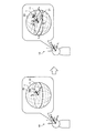
- FIG. 1 is a diagram for describing an outline of an information processing device according to an embodiment of the present disclosure.
- FIG. 3 is a diagram for describing a second calibration process according to the embodiment.
- FIG. 3 is a block diagram illustrating an example of a logical configuration of the information processing apparatus according to the embodiment. It is a figure for explaining generation processing of rotation information according to head direction S concerning the embodiment. It is a figure showing an example of a locus of a position of a head direction in virtual space when rotation of virtual space based on rotation information concerning the embodiment is performed. It is a figure showing an example of a screen displayed by HMD concerning the embodiment. It is a flow chart which shows an example of the flow of rotation correction processing performed by HMD concerning the embodiment.
- FIG. 1 is a diagram for describing an outline of an information processing device according to an embodiment of the present disclosure.
- FIG. 3 is a diagram for describing a second calibration process according to the embodiment.
- FIG. 3 is a block diagram illustrating an example of a logical
- FIG. 11 is a diagram for describing a second calibration process according to a first modification.
- FIG. 11 is a diagram for describing a rotation correction process according to a second modification.
- 15 is a graph showing the amount of change in the height of the camera viewpoint when the camera viewpoint is moved up and down and when the virtual space is rotated in the second modification.
- FIG. 2 is a block diagram illustrating an example of a hardware configuration of the information processing apparatus according to the embodiment.
- FIG. 1 is a diagram for describing an outline of an information processing apparatus according to an embodiment of the present disclosure.
- the information processing device 1 is an HMD (Head Mounted Display).
- a user in the real space 10 wears the HMD 1 and appreciates VR content relating to the virtual space 20 (corresponding to the second space).
- the VR content includes image data of the virtual space 20.
- the VR content may include audio data of the virtual space 20.
- the virtual space 20 is a spherical image.
- the virtual space 20 may be a semi-celestial sphere image (a panoramic image of 90 degrees left and right 360 degrees) or an image having any other imaging range.
- $ HMD1 is an example of an information processing device that reproduces VR content.
- the HMD 1 is mounted on the user's head such that a display unit capable of displaying an image is located in front of the user's eyes. Then, the HMD 1 reproduces (for example, displays and / or outputs audio) the VR content.
- the information processing device that reproduces the VR content may be realized by a smartphone, a tablet terminal, a projector, or the like, in addition to the HMD 1.
- X 1 axis is defined by Y 1 axis and a Z 1 axis.
- the X 1 axis and the Y 1 axis are coordinate axes that define the horizontal plane 11 of the real space 10.
- Y 1 axis is a coordinate axis that matches the horizontal component of the first reference direction
- X 1 axis is a coordinate axis orthogonal to the Y 1 axis.
- Z 1 axis is a coordinate axis coincides with the vertical direction in the real space 10.
- the first reference direction is a direction that is easy for the user to see, and is typically the direction of the horizontal plane 11 of the real space 10.
- the origin of the real space 10 is the viewpoint or head of the user
- the horizontal plane 11 of the real space 10 is a horizontal plane passing through the origin of the real space 10.
- the first reference direction is a direction from the origin of the real space 10 to the other end.
- Coordinate system of the virtual space 20 X 2 axis, defined by Y 2 axis, and Z 2 axes.
- X 2 axis and Y 2 axis is a coordinate axis defining the horizontal surface 21 of the virtual space 20.
- Y 2 axis is a coordinate axis that matches the horizontal component of the second reference direction
- X 2 axis is a coordinate axis perpendicular to the Y 2 axis.
- Z 2 axes are coordinate axes coincides with the vertical direction of the virtual space 20.
- the second reference direction is a direction of a specific position (hereinafter, also referred to as a target position) in the virtual space 20.
- the target position is typically a position in the virtual space 20 that the user wants to see or wants to show to the user.
- the horizontal plane 21 of the virtual space 20 is a horizontal plane originating from the camera position of the VR content.
- the origin of the virtual space 20 is the camera position of the VR content, and the horizontal plane 21 of the virtual space 20 is a horizontal plane passing through the origin of the virtual space 20.
- the second reference direction is a direction from the origin of the virtual space 20 to the other end.
- the HMD 1 first performs a calibration process for determining the attitude of the virtual space 20 with respect to the real space 10.
- the calibration process will be described.
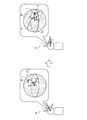
- the left diagram of FIG. 1 shows the real space 10 and the virtual space 20 in the initial state after the first calibration process.
- the initial state refers to a state in which the head direction matches the first reference direction.
- a state other than the initial state that is, a state in which the head direction does not match the first reference direction is also referred to as a changed state.
- the right diagram of FIG. 1 shows a state of the real space 10 and the virtual space 20 in a changed state after the first calibration processing.
- the first calibration process X 1 axis and the X 2 axis coincides, Y 1 axis and a Y 2 axis coincides, and Z 2 axis and Z 2 axes Matches.
- the space recognition of the real space 10 perceived by the user based on the direction of gravity (recognition of the horizontal plane 11 and the vertical direction of the real space 10) and the virtual space 20 perceived based on the image of the virtual space 20 viewed by the user.
- Space recognition (recognition of the horizontal plane 21 and the vertical direction of the virtual space 20) coincides with each other. Therefore, the user can appreciate the virtual space 20 without feeling uncomfortable.
- $ HMD1 displays VR content.
- the HMD 1 displays an image of the position V in the direction S with respect to the user's line of sight (for example, an image of a predetermined area centered on the position V) in the virtual space 20, as shown in the left diagram of FIG. .
- the direction S regarding the user's line of sight may be the user's line of sight or the head direction of the user.
- the line-of-sight direction means the direction of the eyeball (for example, the direction of the gazing point).
- the head direction means the direction of the face.
- the HMD 1 displays an image of the position V in the user's head direction S in the virtual space 20.
- the HMD 1 displays an image of the position V in the head direction S after the change in the virtual space 20. In this way, the user can enjoy the experience of looking around 360 degrees in VR content.
- the pitch angle in the first reference direction that is, the direction that is easy for the user to see
- the pitch angle in the second reference direction that is, the direction of the target position
- the user turns the head direction S in a direction that is easy to see (for example, without tilting the head up and down), and also includes a region including the target position (for example, a predetermined region centered on the target position; This is because it is possible to appreciate the image of the image.
- the pitch angle is a vertical rotation angle with respect to the horizontal plane 11 of the real space 10. For example, if the horizontal component of the head direction S of the user matches with the Y 1 axis, the pitch axis coincides with X 1, the pitch angle is the rotation angle around the X 1 axis.
- the HMD 1 when the first calibration process is performed, the pitch angle in the first reference direction may not match the pitch angle in the second reference direction. Therefore, the HMD 1 according to the present embodiment performs the second calibration process.
- the second calibration process will be described with reference to FIG.
- FIG. 2 is a diagram for explaining the second calibration process according to the present embodiment.
- the left diagram of FIG. 2 shows the state of the real space 10 and the virtual space 20 in the initial state after the first calibration process
- the right diagram of FIG. 2 shows the initial state after the second calibration process.
- 1 shows a state of a real space 10 and a virtual space 20.
- the horizontal plane 11 of the real space 10 and the horizontal plane 21 of the virtual space 20 match by the first calibration process.
- the direction of the target region T is shifted upward from the horizontal plane 11 of the real space 10 (that is, the pitch angle ⁇ 0). Therefore, the user rotates the head direction S around the pitch axis to display the image of the target region T on the HMD 1, that is, in order to match the position V with the target region T.
- the user is obliged to tilt his head upward to appreciate the image of the target area T. Considering that the viewing time of VR content can be long, the burden cannot be ignored.
- the virtual space 20 is rotated in advance so that the first reference direction matches the second reference direction.
- a calibration process is also referred to as a second calibration process.
- the horizontal plane 11 of the real space 10 and the horizontal plane 21 of the virtual space 20 are shifted by the second calibration process.
- the direction of the target area T is located on the horizontal plane 11 of the real space 10 (that is, the pitch angle ⁇ 0), and the position of the head direction S in the initial state.
- V matches the target area T. Therefore, the user can display the image of the target area T on the HMD 1 without rotating the head direction S about the pitch axis. That is, the user can view the image of the target area T without tilting the head up and down. Therefore, the burden imposed on the user when the first calibration process is performed is eliminated.
- the same rotation as the rotation of the virtual space 20 performed in the second calibration process is performed with reference to the head direction S of the user. Accordingly, the virtual space 20 always tilts with respect to the head direction S, and when the user rotates the head direction S along the horizontal plane 11 of the real space 10, the trajectory parallel to the horizontal plane 21 of the virtual space 20 The image in the upper area is displayed. In this way, the user is prevented from misaligning the space between the virtual space and the real space.
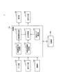
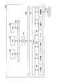
- FIG. 3 is a block diagram illustrating an example of a logical configuration of the information processing device 1 (for example, the HMD 1) according to the present embodiment.
- the HMD 1 includes a sensor unit 110, an operation input unit 120, a communication unit 130, a display unit 140, a sound output unit 150, a storage unit 160, and a control unit 170.
- the sensor unit 110 has a function of detecting various information related to the HMD 1 or the user.
- the sensor unit 110 includes an imaging unit for imaging the eyes of the user.
- the imaging unit includes a lens system including an imaging lens, an aperture, a zoom lens, and a focus lens, a driving system that performs a focus operation and a zoom operation on the lens system, and a photoelectric conversion of imaging light obtained by the lens system.
- a solid-state imaging device array for generating an imaging signal. The imaging unit captures an image of the user's eye, and outputs data of the captured image to the control unit 170.
- the HMD 1 includes a gyro sensor.
- the gyro sensor detects the angular velocity of the HMD 1.
- the gyro sensor includes a vibrator such as a piezoelectric vibrator or a silicon vibrator, and detects an angular velocity based on Coriolis force applied to the vibrating vibrator.
- the gyro sensor outputs information indicating the detected angular velocity to the control unit 170.
- the HMD 1 includes an acceleration sensor.
- the acceleration sensor detects the acceleration of HMD1.
- the acceleration sensor detects acceleration by an arbitrary detection method such as an optical method or a semiconductor method.
- the number of axes for detecting acceleration is arbitrary, and may be, for example, three axes.
- the acceleration sensor outputs information indicating the detected acceleration to the control unit 170.
- the HMD 1 includes a direction sensor.
- the direction sensor has a function of detecting the direction of the HMD 1.
- the azimuth sensor includes a terrestrial magnetism sensor, and based on information indicating the azimuth detected by the terrestrial magnetism sensor and the installation orientation of the terrestrial magnetism sensor in the HMD 1, determines the direction in which the HMD 1 faces (for example, the head direction S described above). To detect.
- the HMD 1 outputs information indicating the detected orientation to the control unit 170.
- Operation input unit 120 has a function of receiving an operation input from a user. For example, the operation input unit 120 receives an input of a calibration start instruction and an operation mode selection instruction from a user. The operation input unit 120 outputs operation input information from the user to the control unit 170.
- the communication unit 130 is an interface that transmits and receives information to and from other devices.
- the communication unit 130 communicates in accordance with any wired or wireless communication standard such as LAN (Local Area Network), wireless LAN, Wi-Fi (registered trademark), Bluetooth (registered trademark), or NFC (Near Field Communication). I do.
- LAN Local Area Network
- Wi-Fi registered trademark
- Bluetooth registered trademark
- NFC Near Field Communication
- the display unit 140 has a function of displaying an image.
- the display unit 140 displays an image of the virtual space 20 based on the control of the output control unit 177.
- Audio output unit 150 The sound output unit 150 has a function of outputting sound. The sound output unit 150 outputs the sound of the virtual space 20 based on the control of the output control unit 177.
- Storage unit 160 has a function of temporarily or non-temporarily storing information for the operation of the HMD 1.
- the storage unit 160 stores, for example, VR content, and stores angle information generated by the rotation information generation unit 175 each time the second calibration process is executed.
- Control unit 170 has a function of controlling the overall operation in the HMD 1. As illustrated in FIG. 3, the control unit 170 includes a gaze-related direction acquisition unit 171, a virtual space information acquisition unit 173, a rotation information generation unit 175, an output control unit 177, and an operation mode selection unit 179.
- the gaze-related direction acquisition unit 171 has a function of acquiring a direction related to the gaze of the user in the real space 10.
- the gaze-related direction acquisition unit 171 outputs the information indicating the acquired direction related to the gaze of the user to the rotation information generation unit 175.
- the virtual space information acquisition unit 173 has a function of acquiring virtual space information that is information on the virtual space 20.
- the virtual space information acquisition unit 173 outputs the acquired virtual space information to the output control unit 177.
- the rotation information generation unit 175 functions as a generation unit that generates rotation information that is information for rotating the virtual space 20.
- the rotation information generation unit 175 outputs the generated rotation information to the output control unit 177.
- the output control unit 177 has a function of causing the output device to output output information to the user based on the virtual space information and the rotation information. For example, the output control unit 177 generates output control information based on virtual space information and rotation information. Next, the output control unit 177 outputs the output control information to the display unit 140 and the audio output unit 150, causes the image of the virtual space 20 to be output to the display unit 140, and outputs the audio of the virtual space 20 to the audio output unit 150. Let it.
- the operation mode selection unit 179 has a function of selecting an operation mode of the output control unit 177.
- the operation mode selection unit 179 outputs information indicating the selected operation mode to the output control unit 177, and switches the operation mode of the output control unit 177.
- the gaze-related direction acquisition unit 171 acquires a direction related to the gaze of the user in the real space 10.
- the direction related to the user's line of sight is described as the head direction, but the direction related to the user's line of sight may be the line of sight.
- the gaze-related direction acquisition unit 171 calculates the position and orientation of the user's head based on the detection results of the gyro sensor, the acceleration sensor, and / or the direction sensor included in the sensor unit 110, and calculates the user's head.
- the head direction of the user is calculated based on the posture of the user.
- the gaze-related direction acquisition unit 171 performs image recognition processing on an image of the user's eye captured by the imaging unit included in the sensor unit 110, and performs the image recognition result and the position and orientation of the user's head. Is calculated based on the calculation result.
- the virtual space information acquisition unit 173 acquires virtual space information.
- the virtual space information corresponds to the VR content described above.
- the virtual space information includes image data of the virtual space 20 and / or audio data of the virtual space 20.
- the virtual space information acquisition unit 173 acquires VR content by receiving VR content via the communication unit 130 or reading VR content stored in the storage unit 160.
- the first reference direction is a direction that is easy for the user to see as described above, and is typically the direction of the horizontal plane 11 of the real space 10.
- the first reference direction may be set as a horizontal component of the head direction S at the start of the second calibration process. Further, the first reference direction may be set as a horizontal component of the head direction S at the start of using the HMD 1 or as a horizontal component of the head direction S when the user faces the front.
- the first reference direction may be set in advance as information accompanying the VR content.
- the second reference direction is a direction of a specific position (hereinafter, also referred to as a target position) in the virtual space 20 as described above.
- the target position is typically a position in the virtual space 20 that the user wants to see or wants to show to the user.
- the target position may be a position of an object such as a person's face or a building, or may be a position other than the object such as a single point in the sky.
- the target position may be set in advance as information accompanying the VR content.
- the target position may be set by the user.
- the target position may be set based on the head direction or the line-of-sight direction of the user.
- a second calibration process in which the position of the object is a specific position is executed. Can be done. At that time, the position of the head direction or the line of sight on the object may be set as the specific position, or the center position of the object may be set as the specific position. As an example of the latter, when the user gazes at a human eye in the virtual space 20, the center position of the human face may be set as the target position. From these, the user can arrange any position in the virtual space 20 in a direction that makes it easy to see.
- the rotation information generating unit 175 obtains angle information for the second calibration process.
- the second calibration processing includes obtaining angle information and rotating the virtual space 20 based on the angle information.
- the rotation of the virtual space 20 based on the angle information is realized by a rotation correction process described later.
- the rotation information generation unit 175 determines the distance between the first reference direction in the real space 10 and the second reference direction in the virtual space 20 when the coordinate system of the real space 10 is associated with the coordinate system of the virtual space 20. Obtain angle information indicating the angle of.
- associating the coordinate system of the real space 10 with the coordinate system of the virtual space 20 means that the origin of the real space 10 and the origin of the virtual space 20 coincide with each other, as in the first calibration process. This means that the horizontal plane 11 of the space 10 matches the horizontal plane 21 of the virtual space 20.
- the rotation information generating unit 175 is matched with the X 1 axis and X 2 axis, it is matched with the Y 1 axis and Y 2 axis, on which was coincident with the Z 2 axis and Z 2 axes, the first The angle information indicating the angle between the reference direction and the second reference direction is obtained.
- the angle information is information indicating an angle in a vertical direction between the first reference direction and the second reference direction with reference to the horizontal plane 11 in the real space 10. More simply, the angle information is a difference between the pitch angle in the first reference direction and the pitch angle in the second reference direction.
- the rotation information generator 175 may acquire angle information based on a calibration start instruction input from the user to the operation input unit 120. Further, the acquisition timing of the angle information may be set in advance as information accompanying the VR content. For example, when the height of the object corresponding to the specific position changes, the rotation information generation unit 175 sets the changed object as the specific position and acquires angle information. In this case, when the first reference direction does not match the second reference direction due to the movement of the object in the virtual space 20 or the like, the first reference direction and the second reference direction are changed again. It is possible to make them coincide.
- the rotation information generation unit 175 When the rotation information generation unit 175 generates the angle information, the rotation information generation unit 175 causes the storage unit 160 to store the generated angle information. Thereafter, the rotation information generation unit 175 performs a rotation correction process described later while continuously using the stored angle information. On the other hand, when the rotation information generation unit 175 regenerates the angle information, the rotation information generation unit 175 updates the angle information stored in the storage unit 160 with the regenerated angle information.
- the rotation information generation unit 175 rotates the virtual space 20 based on the angle information and the direction S (for example, head direction) related to the line of sight of the user in the real space 10.
- the rotation information for causing the rotation is generated.
- the rotation means that the origin of the real space 10 and the origin of the virtual space 20 coincide with each other, and then the virtual space 20 is rotated around an arbitrary axis of the horizontal plane 11 passing through the origin of the real space 10 as a rotation axis.
- Rotation information is information for rotating the virtual space 20 in a vertical direction with respect to the horizontal plane 11 in the real space 10. More specifically, the rotation information is information for rotating the virtual space 20 with respect to the head direction S in the direction from the second reference direction to the first reference direction by the angle indicated by the angle information. .
- To rotate the virtual space 20 with respect to the head direction S means to rotate the virtual space 20 around the rotation axis of the horizontal plane 11 that is orthogonal to the head direction S and passes through the origin of the real space 10 (that is, around the pitch axis). Refers to rotating.
- the output control unit 177 rotates the virtual space 20 using the generated rotation information, and causes the display unit 140 to display information indicating the rotated virtual space 20. More specifically, the output control unit 177 generates an image of the position of the user's head direction S in the rotated virtual space 20 using the rotation information, and causes the display unit 140 to display the image. Rotating the virtual space 20 using such rotation information is also referred to as rotation correction processing. By performing the rotation correction process, as described below, it is possible to match the space recognition of the real space 10 with the space recognition of the virtual space 20 by the user, so that the user does not feel uncomfortable. .
- the rotation information generation unit 175 generates rotation information every time the head direction S changes. Specifically, in the change state, the rotation information generation unit 175 regenerates the rotation information based on the angle information and the changed head direction S. Thus, in the changing state, the space recognition of the real space 10 and the space recognition of the virtual space 20 by the user can be continuously matched.
- FIG. 4 is a diagram for explaining a process of generating rotation information according to the head direction S according to the present embodiment.
- the left diagram of FIG. 4 shows a state of the real space 10 and the virtual space 20 in an initial state after the second calibration processing.
- the right diagram of FIG. 4 illustrates a state of the real space 10 and the virtual space 20 when the rotation correction processing is applied in a changed state after the second calibration processing.
- the execution of the second calibration process results in the first reference direction (head direction S in the initial state) and the second reference direction (target region T).
- the rotation amount R of the virtual space 20 is the rotation amount indicated by the angle information generated in the second calibration process.
- the user In changing state, the user along a horizontal plane 11 in the real space 10 (i.e., Z 1 around the axis) to rotate the head direction S, the rotation information generating unit 175, the angle information and the head direction after the change
- the rotation information is regenerated based on S and the virtual space 20 is rotated based on the regenerated rotation information. More specifically, as shown in the right diagram of FIG. 4, the virtual space 20 is rotated with respect to the changed head direction S by the rotation amount R.
- the rotation amount R shown in the left diagram of FIG. 4 is the same as the rotation amount R shown in the right diagram of FIG.
- the position V in the head direction S after the change coincides with the region T ′ in the virtual space 20.
- the region T ' will be described in detail with reference to FIG.
- FIG. 5 is a diagram illustrating an example of a locus V ′ of the position V in the head direction S in the virtual space 20 when the rotation of the virtual space 20 is performed based on the rotation information according to the present embodiment.
- the trajectory V ′ of the position V in the head direction S passes through the target area T and is parallel to the horizontal plane 21 in the virtual space 20. It is.
- An area T ′ shown in the right diagram of FIG. 4 is an area on the locus V ′.
- the user along a horizontal plane 11 in the real space 10 has been described as rotating the head direction S around, of course, the user is provided with a horizontal surface 11 in the real space 10
- the head direction S can be rotated so as to intersect. Even in this case, the above-described effects are similarly exhibited.
- the rotation information may include a quaternion q for rotating the virtual space 20.
- q t is the quaternion representing the rotation in the vertical direction relative to the horizontal surface 11 in the real space 10 for matching the second reference direction in the first reference direction.
- Quaternion q t is generated based on the angle information.
- q h is rotated in a horizontal plane 11 in the real space 10 between the head direction S and the first reference direction (i.e., rotation about the Z 1 axis) is a quaternion representing a.
- Quaternion q h based on the angle of the horizontal plane 11 between the first reference direction and the current head direction S, is generated.
- the operation mode selection unit 179 selects an operation mode of the output control unit 177.
- the operation mode selection unit 179 can select the operation mode from the first operation mode or the second operation mode.
- the first operation mode is an operation mode in which the rotation of the second space using the above-described rotation information is not performed. Specifically, in the first operation mode, while the second calibration process is performed, the rotation correction process in the changing state is not performed. In the first operation mode, an image corresponding to the head direction S described with reference to the right diagram of FIG. 2 is displayed. That is, in the second operation mode, the space recognition of the real space 10 and the space recognition of the virtual space 20 by the user do not match.
- the second operation mode is an operation mode for rotating the second space using the above-described rotation information. Specifically, in the second operation mode, a second calibration process and a rotation correction process in a changed state are performed. In the second operation mode, the image corresponding to the head direction S described with reference to the right diagram of FIG. 4 and FIG. 5 is displayed. That is, in the second operation mode, the space recognition of the real space 10 and the space recognition of the virtual space 20 by the user match. By selecting such an operation mode, the output control unit 177 can operate in an appropriate operation mode.
- the operation mode selection unit 179 may select an operation mode based on operation input information from the operation input unit 120. For example, the operation input unit 120 accepts an input of an operation mode selection instruction instructing to select the first operation mode or the second operation mode, and the operation mode selection unit 179 operates according to the operation mode selection instruction. Select a mode.
- the operation mode selection unit 179 may select the second operation mode by default when reproducing the VR content. Then, the operation mode selection unit 179 may temporarily select the first operation mode according to an operation mode selection instruction from the user.
- the output control unit 177 may cause the display unit 140 to display information indicating a horizontal line of the virtual space 20.
- the information indicating the horizontal line here is information indicating a line parallel to the horizontal plane 21 of the virtual space 20.
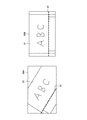
- FIG. 6 is a diagram illustrating an example of a screen displayed by the HMD 1 according to the present embodiment.
- Screen 30A shown in FIG. 6 is displayed in the first operation mode
- screen 30B shown in FIG. 6 is displayed in the second operation mode.
- Any of these screens also user along a horizontal plane 11 in the real space 10 (i.e., Z 1 around the axis) when rotating the head direction S, which is an example of a screen displayed.
- the horizontal direction of these screens is parallel to the horizontal plane 11 of the real space 10.
- Each of these screens is displayed based on a spherical image of the room where the whiteboard 31 is placed.
- a line 32 parallel to the horizontal plane 21 of the virtual space 20 is displayed. Since the line 32 is displayed obliquely with respect to the screen 30A, it can be seen that the horizontal plane 11 of the real space 10 and the horizontal plane of the virtual space 20 intersect. Thereby, the user can recognize that the output control unit 177 is operating in the first operation mode.
- a line 32 parallel to the horizontal plane 21 of the virtual space 20 is displayed. Since the line 32 is displayed horizontally with respect to the screen 30B, it can be seen that the horizontal plane 11 of the real space 10 and the horizontal plane of the virtual space 20 are parallel. Thereby, the user can recognize that the output control unit 177 is operating in the second operation mode.
- the output control unit 177 may localize the sound image of the sound in the virtual space 20 based on the rotation information. For example, when the output position of the sound in the virtual space 20 is defined in the VR content, the output control unit 177 specifies the output position of the sound by rotating the sound output position based on the corrected rotation information. Then, the output control unit 177 localizes the sound image so that the sound in the virtual space 20 is output from the specified output position. Accordingly, the output control unit 177 can prevent a deviation between the image display and the output position of the audio, and can provide a more natural and immersive user experience.
- FIG. 7 is a flowchart illustrating an example of the flow of a rotation correction process performed by the HMD 1 according to the present embodiment.
- the gaze-related direction acquisition unit 171 acquires the head direction S of the user (step S102).
- the rotation information generation unit 175 determines whether to execute the second calibration process (Step S104). For example, when a calibration start instruction is input, the rotation information generation unit 175 determines that the second calibration process is to be performed. When it is determined that the second calibration process is to be performed (step S104 / YES), the rotation information generation unit 175 acquires the angle information (step S106), and the storage unit 160 stores the acquired angle information. (Step S108). Thereafter, the process proceeds to step S110. If it is determined that the second calibration process is not to be performed (step S104 / NO), the process proceeds to step S110.
- the rotation information generation unit 175 generates rotation information based on the head direction S and the angle information stored in the storage unit 160 (Step S110).
- the output control unit 177 rotates the virtual space 20 based on the rotation information (Step S112).
- the output control unit 177 causes the display unit 140 to display an image of the head direction S in the rotated virtual space 20 (step S114).
- Use Case (1) First Use Case The first use case relates to a life log.
- the VR content is a life log recorded as a spherical image.
- the user displays the scene to be remembered on the HMD 1 in order to make it easier to remember the contents.
- the user causes the important part of the scene to be remembered to be subjected to the second calibration processing with the specific position.
- the spherical image of the scene is displayed on the HMD 1.
- the user causes the HMD 1 to execute a second calibration process in which the face of the family requesting to buy a shampoo is set as a specific position, and rotates the omnidirectional image based on the rotation information.
- This allows the user to remove the shampoo from the family in which the face of the family requesting to buy the shampoo is located in a direction that is easy to see, and the spatial recognition of the real space 10 and the spatial recognition of the virtual space 20 by the user match. It is possible to appreciate the image of the scene requested to be purchased.
- the second use case relates to watching sports.
- the VR content is a sports game recorded in a spherical image.
- the spectator seat is located higher than the court / ground where the game is being played, and when viewed from the spectator seat, the court / ground is located downward. Therefore, when the camera viewpoint of the omnidirectional image is located at the spectator seat and the first calibration process is performed, the user is forced to always point the head direction S downward.
- the user causes the HMD 1 to execute a second calibration process with the court / ground as a specific position, and rotates the omnidirectional image based on the rotation information. Accordingly, the user can view an image of a sports game in which the court / ground is located in a direction that is easy to see, and the spatial recognition of the real space 10 and the spatial recognition of the virtual space 20 by the user match. .
- the user can cause the HMD 1 to execute the second calibration process before and after the switching, so that the user can always view the image of the important area while turning the head direction S in a direction that is easy to see. Becomes possible.
- Third use case A third use case relates to a remote-controlled robot.
- the user operates the operating device while wearing the HMD 1, and remotely controls the robot having the work arm.
- the spherical image captured by the spherical camera mounted on the robot is displayed by the HMD 1.
- a second calibration process is performed in which the work position at the tip of the work arm is set as the specific position, and the rotation of the omnidirectional image based on the above-described rotation information is performed. Accordingly, the user can view an image of the work space in which the work position of the tip of the work arm is located in a direction that is easy to see, and the space recognition of the real space 10 and the space recognition of the virtual space 20 by the user match. It becomes possible. As a result, it is possible to reduce the physical load on the user and improve the work efficiency.
- the first reference direction is described as being the direction of the horizontal plane 11 in the real space 10; however, the present technology is not limited to such an example.
- the first reference direction may be a direction shifted by a predetermined angle below the horizontal plane 11 in the real space 10.
- the first reference direction is a direction shifted from 5 degrees to 10 degrees below the horizontal plane 11 in the real space 10. This makes it possible to execute the second calibration process with the direction most visible to the user as the first reference direction.
- the center position of the display unit is often shifted from the viewpoint of the user by 5 degrees to 10 degrees in design. This is because experience has shown that such an angle is easy for the user to see.
- FIG. 8 is a diagram for explaining the second calibration process according to the first modification.
- the left diagram of FIG. 8 illustrates the state of the real space 10 and the virtual space 20 in the initial state after the first calibration process
- the right diagram of FIG. 8 illustrates the initial state after the second calibration process.
- 1 shows a state of a real space 10 and a virtual space 20.
- the left diagram in FIG. 8 is the same as the left diagram in FIG.
- the head direction S of the user coincides with the first reference direction.
- the first reference direction is a direction shifted by a predetermined angle below the horizontal plane 11 in the real space 10.
- the first reference direction matches the second reference direction. Therefore, as shown in the right diagram of FIG. 8, when the user turns the head direction S downward by a predetermined angle based on the horizontal plane 11 in the real space 10, that is, the head direction S matches the first reference direction. Then, the position V in the head direction S matches the target area T in the second reference direction.
- the first reference direction is a direction shifted downward by a predetermined angle with respect to the horizontal plane 11 in the real space 10. Therefore, the target area T is moved to the horizontal plane 11 in the real space 10 by the second calibration process. It will be located lower than this.
- the virtual space 20 is described as an omnidirectional image, but the present technology is not limited to such an example.
- the virtual space 20 may be a modeled three-dimensional space.
- the HMD 1 changes the posture of the camera in the modeled three-dimensional space according to the change in the head direction S of the user, and displays an image obtained by the camera. Further, the HMD 1 rotates the horizontal plane (coordinate system) of the entire world in the three-dimensional space modeled according to the rotation information.
- the HMD 1 may move the camera viewpoint up and down instead of using the rotation information to rotate the horizontal plane of the entire world in the three-dimensional space as the rotation correction processing.
- FIG. 9 is a diagram for explaining a rotation correction process according to the second modification.
- the first reference direction is the direction of the horizontal plane 11 of the real space 10. That is, in the initial state, it is assumed that the head direction S of the user faces the horizontal plane 11 of the real space 10.
- FIG. 9 shows the relationship between the position of the camera C and the position of the target area T in the virtual space 20 when the first calibration processing has been performed.
- the imaging direction 23 of the camera C is parallel to the ground 22.
- the height of the camera C from the ground 22 is L
- the height of the target area T from the ground 22 is L + H.
- the imaging direction 23 of the camera C is parallel to the ground 22, and the angle between the imaging direction 23 of the camera C and the direction 24 from the camera C to the target area T is ⁇ .
- FIG. 9 shows the position of the camera C in the virtual space 20 in the initial state and the target area T when the height of the camera viewpoint is moved to the height of the target area T as the second calibration processing. Shows the relationship with the position.
- the imaging direction 23 of the camera C is oriented in a direction parallel to the ground 22.
- the height of the camera C from the ground 22 is L + H, which is the same as the height L + H of the target area T from the ground 22. Therefore, in the initial state, the imaging direction 23 of the camera C is parallel to the ground 22, and coincides with the imaging direction 23 of the camera C and the direction 24 from the camera C to the target area T.
- the imaging direction 23 of the camera C rotates horizontally while keeping the ground 22 parallel. Therefore, an image of an area on a trajectory that passes through the target area T and is parallel to the ground 22 is displayed. Therefore, since the space recognition of the real space 10 and the space recognition of the virtual space 20 by the user match, it is possible to prevent the user from feeling uncomfortable.
- the right diagram of FIG. 9 illustrates the relationship between the position of the camera C and the position of the target region T in the virtual space 20 in the initial state when the virtual space 20 is rotated based on the rotation information as the second calibration process. Is shown.
- the posture of the camera C is inclined by ⁇ , and as a result, the imaging direction 23 of the camera C matches the direction 24 from the camera C to the target area T.
- the imaging direction 23 of the camera C is in a direction crossing the ground 22.
- the virtual height of the camera C from the ground 22 is L / cos ⁇
- the height of the target area T from the ground 22 is L + H.
- the camera C rotates parallel to the ground 22 while maintaining the inclination ⁇ . Thereby, an image of an area on a trajectory that passes through the target area T and is parallel to the ground 22 is displayed. Therefore, since the space recognition of the real space 10 and the space recognition of the virtual space 20 by the user match, it is possible to prevent the user from feeling uncomfortable.
- the height of the camera C is L + H.
- the virtual height of the camera C is L / cos ⁇ .
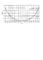
- ⁇ satisfies ⁇ / 2 ⁇ ⁇ / 2. That is, when the camera viewpoint is moved up and down, the amount of change in the height of the camera C is
- Expression (2) when the relationship of Expression (3) is satisfied, the height change of the camera C is smaller when the virtual space 20 is rotated than when the camera viewpoint is moved up and down. Can be said to be superior.
- > L / cos ⁇ L, tan ⁇ H / D (2) (1 ⁇ cos ⁇ ) 2 / (1 ⁇ cos 2 ⁇ ) ⁇ (D / L) 2 (3)
- FIG. 10 is a graph showing the amount of change in the height of the camera viewpoint when the camera viewpoint is moved up and down and when the virtual space 20 is rotated in the second modification.
- ⁇ is ⁇ 60 degrees to +60 degrees
- the above equation (3) is established.
- ⁇ is ⁇ 90 degrees to ⁇ 60 degrees and when ⁇ is +60 degrees to +90 degrees
- the above equation (3) is changed to It doesn't hold. That is, in many cases, it is understood that the above equation (3) holds. From this, it can be seen that, in many cases, when the virtual space 20 is rotated, the height change of the camera C is smaller and superior than when the camera viewpoint is moved up and down.
- FIG. 11 is a block diagram illustrating an example of a hardware configuration of the information processing apparatus according to the present embodiment.
- the information processing device 900 illustrated in FIG. 11 can realize, for example, the information processing device 1 illustrated in FIG.
- Information processing by the information processing apparatus 1 according to the present embodiment is realized by cooperation of software and hardware described below.
- the information processing apparatus 900 includes a CPU (Central Processing Unit) 901, a ROM (Read Only Memory) 902, a RAM (Random Access Memory) 903, and a host bus 904 a.
- the information processing device 900 includes a bridge 904, an external bus 904b, an interface 905, an input device 906, an output device 907, a storage device 908, a drive 909, a connection port 911, and a communication device 913.
- the information processing device 900 may include a processing circuit such as an electric circuit, a DSP, or an ASIC, instead of or in addition to the CPU 901.
- the CPU 901 functions as an arithmetic processing device and a control device, and controls overall operations in the information processing device 900 according to various programs. Further, the CPU 901 may be a microprocessor.
- the ROM 902 stores programs used by the CPU 901 and operation parameters.
- the RAM 903 temporarily stores a program used in the execution of the CPU 901 and parameters that change as appropriate in the execution.
- the CPU 901 may form, for example, the control unit 170 illustrated in FIG.
- the CPU 901, the ROM 902, and the RAM 903 are mutually connected by a host bus 904a including a CPU bus and the like.
- the host bus 904a is connected via a bridge 904 to an external bus 904b such as a PCI (Peripheral Component Interconnect / Interface) bus.
- PCI Peripheral Component Interconnect / Interface
- the host bus 904a, the bridge 904, and the external bus 904b do not necessarily need to be separately configured, and these functions may be mounted on one bus.
- the input device 906 is realized by a device to which information is input by a user, such as a mouse, a keyboard, a touch panel, a button, a microphone, a switch, and a lever. Further, the input device 906 may be, for example, a remote control device using infrared rays or other radio waves, or may be an externally connected device such as a mobile phone or a PDA corresponding to the operation of the information processing device 900. . Further, the input device 906 may include, for example, an input control circuit that generates an input signal based on information input by a user using the above-described input unit and outputs the input signal to the CPU 901. By operating the input device 906, the user of the information processing device 900 can input various data to the information processing device 900 or instruct a processing operation. These input devices 906 can form, for example, the operation input unit 120 shown in FIG.
- the input device 906 may be formed by a device that detects information about the user.
- the input device 906 includes various sensors such as an image sensor (for example, a camera), a depth sensor (for example, a stereo camera), an acceleration sensor, a gyro sensor, a geomagnetic sensor, an optical sensor, a sound sensor, a distance measuring sensor, and a force sensor. May be included.
- the input device 906 is used for information about the state of the information processing device 900 itself, such as the posture and the moving speed of the information processing device 900, and information about the surrounding environment of the information processing device 900, such as brightness and noise around the information processing device 900. May be obtained.
- the input device 906 receives a GNSS signal (for example, a GPS signal from a GPS (Global Positioning System) satellite) from a GNSS (Global Navigation Satellite System) satellite, and receives position information including the latitude, longitude, and altitude of the device.
- a GNSS module for measuring may be included.
- the input device 906 may be a device that detects the position by Wi-Fi (registered trademark), transmission / reception with a mobile phone / PHS / smartphone, or the like, or short-range communication.
- These input devices 906 may form, for example, the sensor unit 110 shown in FIG.
- the output device 907 is formed of a device capable of visually or audibly notifying the user of the acquired information. Examples of such devices include CRT display devices, liquid crystal display devices, plasma display devices, EL display devices, display devices such as laser projectors, LED projectors and lamps, audio output devices such as speakers and headphones, and printer devices. . Another display device is a retinal projection display that projects an image directly on a user's retina.
- the output device 907 outputs, for example, results obtained by various processes performed by the information processing device 900. Specifically, the display device visually displays the results obtained by various processes performed by the information processing device 900 in various formats such as text, images, tables, and graphs.
- the audio output device converts an audio signal composed of reproduced audio data, acoustic data, and the like into an analog signal and outputs it audibly.
- the display device may form, for example, the display unit 140 illustrated in FIG.
- the audio output device may form, for example, the audio output unit 150 shown in FIG.
- the storage device 908 is a data storage device formed as an example of a storage unit of the information processing device 900.
- the storage device 908 is realized by, for example, a magnetic storage device such as an HDD, a semiconductor storage device, an optical storage device, or a magneto-optical storage device.
- the storage device 908 may include a storage medium, a recording device that records data on the storage medium, a reading device that reads data from the storage medium, a deletion device that deletes data recorded on the storage medium, and the like.
- the storage device 908 stores programs executed by the CPU 901 and various data, various data acquired from the outside, and the like.
- the storage device 908 may form, for example, the storage unit 160 illustrated in FIG.
- the drive 909 is a reader / writer for a storage medium, and is built in or external to the information processing apparatus 900.
- the drive 909 reads information recorded on a removable storage medium such as a mounted magnetic disk, optical disk, magneto-optical disk, or semiconductor memory, and outputs the information to the RAM 903.
- the drive 909 can also write information on a removable storage medium.
- connection port 911 is an interface connected to an external device, and is a connection port with an external device capable of transmitting data by USB (Universal Serial Bus), for example.
- USB Universal Serial Bus
- the communication device 913 is a communication interface formed of, for example, a communication device for connecting to the network 920.
- the communication device 913 is, for example, a communication card for a wired or wireless LAN (Local Area Network), LTE (Long Term Evolution), Bluetooth (registered trademark), or WUSB (Wireless USB).
- the communication device 913 may be a router for optical communication, a router for ADSL (Asymmetric Digital Subscriber Line), a modem for various communication, or the like.
- the communication device 913 can transmit and receive signals and the like to and from the Internet and other communication devices in accordance with a predetermined protocol such as TCP / IP.
- the communication device 913 may form, for example, the communication unit 130 illustrated in FIG.
- the network 920 is a wired or wireless transmission path for information transmitted from a device connected to the network 920.
- the network 920 may include a public line network such as the Internet, a telephone line network, a satellite communication network, various LANs including Ethernet (registered trademark) (Local Area Network), a WAN (Wide Area Network), and the like.
- the network 920 may include a dedicated line network such as an IP-VPN (Internet ⁇ Protocol-Virtual ⁇ Private ⁇ Network).
- a computer program for realizing each function of the information processing device 900 according to the present embodiment as described above can be created and mounted on a PC or the like.
- a computer-readable recording medium in which such a computer program is stored can be provided.
- the recording medium is, for example, a magnetic disk, an optical disk, a magneto-optical disk, a flash memory, or the like.
- the above-described computer program may be distributed, for example, via a network without using a recording medium.
- the information processing apparatus 1 includes the first reference direction in the real space 10 and the virtual space when the coordinate system of the real space 10 is associated with the coordinate system of the virtual space 20.
- the angle information indicating the angle with the second reference direction at 20 is obtained.
- the information processing device 1 generates rotation information for rotating the virtual space 20 based on the angle information and the direction related to the line of sight of the user in the real space 10.
- the information processing apparatus 1 can rotate the virtual space 20 and display an image of an area in the direction related to the user's line of sight in the rotated virtual space 20.
- the user can view the image of the area in the first reference direction in the virtual space 20 without tilting the head up and down.
- the virtual space 20 is always inclined with respect to the direction related to the user's line of sight.
- the user rotates the head direction S along the horizontal plane 11 of the real space 10
- the image of the area on the trajectory parallel to 21 is displayed. This prevents the user from perceiving the space between the virtual space and the real space.
- control unit 170 includes the sensor unit 110, the operation input unit 120, the communication unit 130, the display unit 140, the audio output unit 150, and the storage unit 160. It may be provided in a device such as a server connected via a network or the like.
- the angle between the first reference direction in the first space and the second reference direction in the second space when the coordinate system of the first space is associated with the coordinate system of the second space A generation unit that generates rotation information for rotating the second space based on the angle information indicating the direction and the direction related to the line of sight of the user in the first space.
- An information processing apparatus comprising: (2) The information processing device according to (1), wherein the rotation information is information for rotating the second space in a vertical direction with respect to a horizontal plane in the first space. (3) The rotation information is for rotating the second space in a direction from the second reference direction to a first reference direction with respect to a line of sight of the user by an angle indicated by the angle information.
- the information processing apparatus which is information.
- the angle information is information indicating an angle in a vertical direction with respect to a horizontal plane in the first space between the first reference direction and the second reference direction.
- the information processing apparatus according to any one of (3).
- the information processing apparatus includes an output control unit configured to rotate the second space using the rotation information and to display information indicating the rotated second space on a display unit, The information processing device according to any one of 6).
- the information processing apparatus further includes an operation mode selection unit that selects an operation mode of the output control unit from a first operation mode or a second operation mode.
- the first operation mode is an operation mode in which the rotation of the second space using the rotation information is not performed,
- the information processing device according to (7), wherein the second operation mode is an operation mode in which the second space is rotated using the rotation information.
- the information processing device (9) The information processing device according to (7) or (8), wherein the output control unit displays information indicating a horizontal line of the second space. (10) The information processing device according to any one of (7) to (9), wherein the output control unit localizes a sound image of a sound in the second space based on the rotation information. (11) The information processing apparatus according to any one of (1) to (10), wherein the direction regarding the user's line of sight is the user's line of sight. (12) The information processing apparatus according to any one of (1) to (10), wherein the direction related to the user's line of sight is a head direction of the user. (13) The information processing apparatus according to any one of (1) to (12), wherein the first reference direction is a direction of a horizontal plane in the first space.
- the information processing apparatus according to any one of (1) to (12), wherein the first reference direction is a direction shifted downward by a predetermined angle with respect to a horizontal plane in the first space.
- the second reference direction is a direction of a specific position in the second space.
- the specific position is set based on a direction related to a line of sight of the user.
- the information processing apparatus according to any one of (1) to (16), wherein the first space is a real space, and the second space is a spherical image.
- HMD Reference Signs List 10 real space 11 horizontal plane of real space 20 virtual space 21 horizontal plane of virtual space 110 sensor unit 120 operation input unit 130 communication unit 140 display unit 150 sound output unit 160 storage unit 170 control unit 171 gaze-related direction acquisition unit 173 acquisition of virtual space information Unit 175 Rotation information generation unit 177 Output control unit 179 Operation mode selection unit
Landscapes
- Engineering & Computer Science (AREA)
- General Engineering & Computer Science (AREA)
- Theoretical Computer Science (AREA)
- Physics & Mathematics (AREA)
- General Physics & Mathematics (AREA)
- Human Computer Interaction (AREA)
- Computer Graphics (AREA)
- Computer Hardware Design (AREA)
- Software Systems (AREA)
- User Interface Of Digital Computer (AREA)
- Processing Or Creating Images (AREA)
- Position Input By Displaying (AREA)
Abstract
An information processing device equipped with a generation unit (175) for generating rotation information for rotating a second space (20), on the basis of angle information indicating an angle between a first reference direction in a first space (10) and a second reference direction in the second space when a coordinate system of the first space and a coordinate system of the second space are associated with each other, and a direction related to the line of sight of user in the first space.
Description
本開示は、情報処理装置、情報処理方法及びプログラムに関する。
The present disclosure relates to an information processing device, an information processing method, and a program.
近年、VR(Virtual Reality)技術が様々な場面で活用されている。例えば、VR技術は、遠隔地にいるユーザ同士のコミュニケーション支援、及び没入感の高い視覚コンテンツの提供等の、様々な場面で活用されている。
In recent years, VR (Virtual Reality) technology has been used in various situations. For example, VR technology is utilized in various situations, such as supporting communication between users in remote locations and providing highly immersive visual content.
VR技術とは、仮想空間を実空間であるかのようにユーザに知覚させる技術である。その一例として、全天球画像(上下左右全方位の360度パノラマ画像)を仮想空間として用いる技術が開発されている。
VR technology is a technology that allows a user to perceive a virtual space as if it were a real space. As one example, a technology has been developed in which a celestial sphere image (a 360-degree panoramic image in all directions, up, down, left, and right) is used as a virtual space.
例えば、下記特許文献1では、撮像装置により撮像された撮像画像に基づいて全天球画像を生成し、生成した全天球画像のうちユーザの頭部方向に相当する領域を表示する技術が開示されている。かかる技術によれば、ユーザが頭部方向を変化させると、全天球画像のうち変化後の頭部方向の領域が表示されるので、ユーザは、あたかも撮像された実空間にいるかのような感覚を得ることができる。
For example, Patent Literature 1 below discloses a technique in which an omnidirectional image is generated based on a captured image captured by an imaging device, and an area corresponding to the head direction of the user in the generated omnidirectional image is displayed. Have been. According to this technique, when the user changes the head direction, the changed head direction area of the celestial sphere image is displayed, so that the user is as if in the real space where the image was taken. You can get a feeling.
しかしながら、上記の特許文献1などで提案されているVR技術は、未だ開発されてから日が浅く、さまざまな局面でVRを活用するための技術が十分に提案されているとはいいがたい。例えば、ユーザによる仮想空間と実空間との空間認識のずれを防止するための技術も、十分には提案されていないものの一つである。
However, since the VR technology proposed in Patent Document 1 and the like has not been developed yet, it cannot be said that a technology for utilizing VR in various aspects has been sufficiently proposed. For example, a technique for preventing a user from misaligning a space between a virtual space and a real space has not been proposed yet.
そこで、本開示では、ユーザによる仮想空間と実空間との空間認識のずれを防止することが可能な仕組みを提供する。
Therefore, the present disclosure provides a mechanism that can prevent a user from shifting the spatial recognition between the virtual space and the real space.
本開示によれば、第1の空間の座標系と第2の空間の座標系とを対応付けたときの前記第1の空間における第1の基準方向と前記第2の空間における第2の基準方向との間の角度を示す角度情報、及び前記第1の空間にいるユーザの視線に関する方向に基づいて、前記第2の空間を回転させるための回転情報を生成する生成部、を備える情報処理装置が提供される。
According to the present disclosure, a first reference direction in the first space and a second reference in the second space when the coordinate system of the first space is associated with the coordinate system of the second space A generation unit configured to generate rotation information for rotating the second space based on angle information indicating an angle between the second space and a direction related to a line of sight of a user in the first space. An apparatus is provided.
また、本開示によれば、第1の空間の座標系と第2の空間の座標系とを対応付けたときの前記第1の空間における第1の基準方向と前記第2の空間における第2の基準方向との間の角度を示す角度情報、及び前記第1の空間にいるユーザの視線に関する方向に基づいて、前記第2の空間を回転させるための回転情報をプロセッサにより生成すること、を含む情報処理方法が提供される。
According to the present disclosure, the first reference direction in the first space and the second reference direction in the second space when the coordinate system of the first space and the coordinate system of the second space are associated with each other. Generating, by a processor, rotation information for rotating the second space based on angle information indicating an angle between the reference direction and the direction related to the line of sight of the user in the first space. An information processing method is provided.
また、本開示によれば、コンピュータを、第1の空間の座標系と第2の空間の座標系とを対応付けたときの前記第1の空間における第1の基準方向と前記第2の空間における第2の基準方向との間の角度を示す角度情報、及び前記第1の空間にいるユーザの視線に関する方向に基づいて、前記第2の空間を回転させるための回転情報を生成する生成部、として機能させるためのプログラムが提供される。
Further, according to the present disclosure, a computer is configured to associate a first reference direction in the first space with a coordinate system in the first space and a coordinate system in the second space with the second space. A generating unit that generates rotation information for rotating the second space based on angle information indicating an angle between the second space and the second reference direction and a direction related to a line of sight of a user in the first space. , A program for functioning as a program is provided.
以上説明したように本開示によれば、ユーザによる仮想空間と実空間との空間認識のずれを防止することが可能となる。なお、上記の効果は必ずしも限定的なものではなく、上記の効果とともに、または上記の効果に代えて、本明細書に示されたいずれかの効果、または本明細書から把握され得る他の効果が奏されてもよい。
As described above, according to the present disclosure, it is possible to prevent a user from misaligning a space between a virtual space and a real space. Note that the above effects are not necessarily limited, and any of the effects shown in the present specification or other effects that can be grasped from the present specification are used together with or in place of the above effects. May be played.
以下に添付図面を参照しながら、本開示の好適な実施の形態について詳細に説明する。なお、本明細書及び図面において、実質的に同一の機能構成を有する構成要素については、同一の符号を付することにより重複説明を省略する。
Hereinafter, preferred embodiments of the present disclosure will be described in detail with reference to the accompanying drawings. In the specification and the drawings, components having substantially the same functional configuration are denoted by the same reference numerals, and redundant description is omitted.
なお、説明は以下の順序で行うものとする。
1.はじめに
1.1.情報処理装置の概要
1.2.技術的課題
1.3.提案技術の概要
2.構成例
3.技術的特徴
3.1.ユーザの視線に関する情報の取得
3.2.仮想空間情報の取得
3.3.回転補正処理
3.4.動作モード選択
3.5.音像定位
4.処理の流れ
5.ユースケース
6.変形例
7.ハードウェア構成例
8.まとめ The description will be made in the following order.
1. Introduction 1.1. Overview of information processing device 1.2. Technical issues 1.3. 1. Overview of the proposed technology Configuration example Technical features 3.1. Acquisition of information on user's line of sight 3.2. Acquisition of virtual space information 3.3. Rotation correction processing 3.4. Operation mode selection 3.5. 3. Sound image localization Processing flow Use case 6. Modification 7. 7. Hardware configuration example Conclusion
<<1.はじめに>>
<1.1.情報処理装置の概要>
図1は、本開示の一実施形態に係る情報処理装置の概要を説明するための図である。図1に示した例では、情報処理装置1は、HMD(Head Mounted Display)である。実空間10(第1の空間に相当)にいるユーザは、HMD1を装着し、仮想空間20(第2の空間に相当)に関するVRコンテンツを鑑賞する。なお、VRコンテンツとは、仮想空間20の画像データを含む。VRコンテンツは、仮想空間20の音声データを含んでいてもよい。以下では、一例として、仮想空間20は全天球画像であるものとする。なお、仮想空間20は、半天球画像(上90度左右360度のパノラマ画像)又はその他の任意の撮像範囲を有する画像であってもよい。 << 1. Introduction >>
<1.1. Overview of information processing device>
FIG. 1 is a diagram for describing an outline of an information processing apparatus according to an embodiment of the present disclosure. In the example shown in FIG. 1, theinformation processing device 1 is an HMD (Head Mounted Display). A user in the real space 10 (corresponding to the first space) wears the HMD 1 and appreciates VR content relating to the virtual space 20 (corresponding to the second space). Note that the VR content includes image data of the virtual space 20. The VR content may include audio data of the virtual space 20. Hereinafter, as an example, it is assumed that the virtual space 20 is a spherical image. The virtual space 20 may be a semi-celestial sphere image (a panoramic image of 90 degrees left and right 360 degrees) or an image having any other imaging range.
<1.1.情報処理装置の概要>
図1は、本開示の一実施形態に係る情報処理装置の概要を説明するための図である。図1に示した例では、情報処理装置1は、HMD(Head Mounted Display)である。実空間10(第1の空間に相当)にいるユーザは、HMD1を装着し、仮想空間20(第2の空間に相当)に関するVRコンテンツを鑑賞する。なお、VRコンテンツとは、仮想空間20の画像データを含む。VRコンテンツは、仮想空間20の音声データを含んでいてもよい。以下では、一例として、仮想空間20は全天球画像であるものとする。なお、仮想空間20は、半天球画像(上90度左右360度のパノラマ画像)又はその他の任意の撮像範囲を有する画像であってもよい。 << 1. Introduction >>
<1.1. Overview of information processing device>
FIG. 1 is a diagram for describing an outline of an information processing apparatus according to an embodiment of the present disclosure. In the example shown in FIG. 1, the
HMD1は、VRコンテンツを再生する情報処理装置の一例である。HMD1は、画像を表示可能な表示部がユーザの眼の前に位置するようにして、ユーザの頭部に装着される。そして、HMD1は、VRコンテンツを再生(例えば、表示及び/又は音声出力)する。VRコンテンツを再生する情報処理装置は、HMD1の他にも、スマートフォン、タブレット端末又はプロジェクタ等により実現されてもよい。
$ HMD1 is an example of an information processing device that reproduces VR content. The HMD 1 is mounted on the user's head such that a display unit capable of displaying an image is located in front of the user's eyes. Then, the HMD 1 reproduces (for example, displays and / or outputs audio) the VR content. The information processing device that reproduces the VR content may be realized by a smartphone, a tablet terminal, a projector, or the like, in addition to the HMD 1.
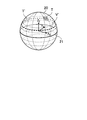
実空間10の座標系は、X1軸、Y1軸及びZ1軸により定義される。X1軸及びY1軸は、実空間10の水平面11を定義する座標軸である。詳しくは、Y1軸は第1の基準方向の水平成分に一致する座標軸であり、X1軸はY1軸に直交する座標軸である。また、Z1軸は、実空間10の鉛直方向に一致する座標軸である。第1の基準方向とは、ユーザにとって見やすい方向であり、典型的には実空間10の水平面11の方向である。実空間10の原点は、ユーザの視点又は頭部であり、実空間10の水平面11とは、実空間10の原点を通る水平面であるものとする。また、第1の基準方向とは、実空間10の原点を一端とする他端への方向である。
Coordinate system of the real space 10, X 1 axis is defined by Y 1 axis and a Z 1 axis. The X 1 axis and the Y 1 axis are coordinate axes that define the horizontal plane 11 of the real space 10. For details, Y 1 axis is a coordinate axis that matches the horizontal component of the first reference direction, X 1 axis is a coordinate axis orthogonal to the Y 1 axis. Further, Z 1 axis is a coordinate axis coincides with the vertical direction in the real space 10. The first reference direction is a direction that is easy for the user to see, and is typically the direction of the horizontal plane 11 of the real space 10. The origin of the real space 10 is the viewpoint or head of the user, and the horizontal plane 11 of the real space 10 is a horizontal plane passing through the origin of the real space 10. The first reference direction is a direction from the origin of the real space 10 to the other end.
仮想空間20の座標系は、X2軸、Y2軸、及びZ2軸により定義される。X2軸及びY2軸は、仮想空間20の水平面21を定義する座標軸である。詳しくは、Y2軸は第2の基準方向の水平成分に一致する座標軸であり、X2軸はY2軸に直交する座標軸である。また、Z2軸は、仮想空間20の鉛直方向に一致する座標軸である。第2の基準方向とは、仮想空間20における特定の位置(以下、対象位置とも称する)の方向である。対象位置は、典型的には、仮想空間20のうちユーザが見たい、又はユーザに見せたい位置である。仮想空間20の水平面21とは、VRコンテンツのカメラ位置を原点する水平面であるものとする。仮想空間20の原点は、VRコンテンツのカメラ位置であり、仮想空間20の水平面21とは、仮想空間20の原点を通る水平面であるものとする。また、第2の基準方向とは、仮想空間20の原点を一端とする他端への方向である。
Coordinate system of the virtual space 20, X 2 axis, defined by Y 2 axis, and Z 2 axes. X 2 axis and Y 2 axis is a coordinate axis defining the horizontal surface 21 of the virtual space 20. For details, Y 2 axis is a coordinate axis that matches the horizontal component of the second reference direction, X 2 axis is a coordinate axis perpendicular to the Y 2 axis. Further, Z 2 axes are coordinate axes coincides with the vertical direction of the virtual space 20. The second reference direction is a direction of a specific position (hereinafter, also referred to as a target position) in the virtual space 20. The target position is typically a position in the virtual space 20 that the user wants to see or wants to show to the user. The horizontal plane 21 of the virtual space 20 is a horizontal plane originating from the camera position of the VR content. The origin of the virtual space 20 is the camera position of the VR content, and the horizontal plane 21 of the virtual space 20 is a horizontal plane passing through the origin of the virtual space 20. The second reference direction is a direction from the origin of the virtual space 20 to the other end.
HMD1は、まず、実空間10に対する仮想空間20の姿勢を決定する、キャリブレーション処理を行う。以下、キャリブレーション処理について説明する。
The HMD 1 first performs a calibration process for determining the attitude of the virtual space 20 with respect to the real space 10. Hereinafter, the calibration process will be described.
(1)第1のキャリブレーション処理
典型的なVR技術においては、キャリブレーション処理において、実空間10の原点と仮想空間20の原点とを一致させた上で、実空間10の水平面11と仮想空間20の水平面21とを一致させる処理が行われる。このようなキャリブレーション処理を、第1のキャリブレーション処理とも称する。 (1) First Calibration Process In a typical VR technique, in a calibration process, the origin of thereal space 10 and the origin of the virtual space 20 are matched, and then the horizontal plane 11 of the real space 10 and the virtual space A process of matching the horizontal plane 21 with the horizontal plane 21 is performed. Such a calibration process is also referred to as a first calibration process.
典型的なVR技術においては、キャリブレーション処理において、実空間10の原点と仮想空間20の原点とを一致させた上で、実空間10の水平面11と仮想空間20の水平面21とを一致させる処理が行われる。このようなキャリブレーション処理を、第1のキャリブレーション処理とも称する。 (1) First Calibration Process In a typical VR technique, in a calibration process, the origin of the
図1の左図は、第1のキャリブレーション処理後の初期状態における実空間10及び仮想空間20の様子を示している。なお、初期状態とは、頭部方向と第1の基準方向とが一致する状態を指す。これに対し、初期状態以外の状態、即ち頭部方向と第1の基準方向とが一致しない状態を、変化状態とも称する。図1の右図は、第1のキャリブレーション処理後の変化状態における実空間10及び仮想空間20の様子を示している。
左 The left diagram of FIG. 1 shows the real space 10 and the virtual space 20 in the initial state after the first calibration process. Note that the initial state refers to a state in which the head direction matches the first reference direction. On the other hand, a state other than the initial state, that is, a state in which the head direction does not match the first reference direction is also referred to as a changed state. The right diagram of FIG. 1 shows a state of the real space 10 and the virtual space 20 in a changed state after the first calibration processing.
図1の左図に示す例では、第1のキャリブレーション処理により、X1軸とX2軸とが一致し、Y1軸とY2軸とが一致し、Z2軸とZ2軸とが一致する。これにより、ユーザが重力方向に基づいて知覚する実空間10の空間認識(実空間10の水平面11及び鉛直方向の認識)と、ユーザが見る仮想空間20の画像に基づいて知覚する仮想空間20の空間認識(仮想空間20の水平面21及び鉛直方向の認識)と、が一致することとなる。従って、ユーザは、違和感なく仮想空間20を鑑賞することができる。
In the example shown in the left diagram of FIG. 1, the first calibration process, X 1 axis and the X 2 axis coincides, Y 1 axis and a Y 2 axis coincides, and Z 2 axis and Z 2 axes Matches. Thereby, the space recognition of the real space 10 perceived by the user based on the direction of gravity (recognition of the horizontal plane 11 and the vertical direction of the real space 10) and the virtual space 20 perceived based on the image of the virtual space 20 viewed by the user. Space recognition (recognition of the horizontal plane 21 and the vertical direction of the virtual space 20) coincides with each other. Therefore, the user can appreciate the virtual space 20 without feeling uncomfortable.
HMD1は、VRコンテンツを表示する。その際、HMD1は、図1の左図に示すように、仮想空間20のうち、ユーザの視線に関する方向Sの位置Vの画像(例えば、位置Vを中心とする所定領域の画像)を表示する。ユーザの視線に関する方向Sとは、ユーザの視線方向であってもよいし、ユーザの頭部方向であってもよい。視線方向とは、眼球の方向(例えば、注視点の方向)を意味する。頭部方向とは、顔の向きを意味する。以下では、ユーザの視線に関する方向Sは、頭部方向であるものとして説明する。
$ HMD1 displays VR content. At that time, the HMD 1 displays an image of the position V in the direction S with respect to the user's line of sight (for example, an image of a predetermined area centered on the position V) in the virtual space 20, as shown in the left diagram of FIG. . The direction S regarding the user's line of sight may be the user's line of sight or the head direction of the user. The line-of-sight direction means the direction of the eyeball (for example, the direction of the gazing point). The head direction means the direction of the face. Hereinafter, a description will be given assuming that the direction S regarding the user's line of sight is the head direction.
キャリブレーション処理後、ユーザが頭部方向Sを変化させると、HMD1は、仮想空間20におけるユーザの頭部方向Sの位置Vの画像を表示する。図1の右図に示した例では、HMD1は、仮想空間20のうち変化後の頭部方向Sの位置Vの画像を表示する。このようにして、ユーザは、VRコンテンツ内で360度ぐるりと回りを見渡す体験を享受することができる。
When the user changes the head direction S after the calibration process, the HMD 1 displays an image of the position V in the user's head direction S in the virtual space 20. In the example illustrated in the right diagram of FIG. 1, the HMD 1 displays an image of the position V in the head direction S after the change in the virtual space 20. In this way, the user can enjoy the experience of looking around 360 degrees in VR content.
(2)第2のキャリブレーション処理
第1の基準方向(即ち、ユーザにとって見やすい方向)のピッチ角と第2の基準方向(即ち、対象位置の方向)のピッチ角とは、一致することが望ましい。その場合、ユーザは、見やすい方向に頭部方向Sを向けながら(例えば、頭を上下に傾けずに)、対象位置を含む領域(例えば、対象位置を中心とする所定領域、以下、対象領域とも称する)の画像を鑑賞することができるためである。ここでのピッチ角とは、実空間10の水平面11を基準とする上下方向の回転角度であるものとする。例えば、ユーザの頭部方向Sの水平成分がY1軸と一致する場合、ピッチ軸はX1と一致し、ピッチ角はX1軸まわりの回転角度となる。 (2) Second Calibration Process It is desirable that the pitch angle in the first reference direction (that is, the direction that is easy for the user to see) and the pitch angle in the second reference direction (that is, the direction of the target position) match. . In this case, the user turns the head direction S in a direction that is easy to see (for example, without tilting the head up and down), and also includes a region including the target position (for example, a predetermined region centered on the target position; This is because it is possible to appreciate the image of the image. Here, the pitch angle is a vertical rotation angle with respect to thehorizontal plane 11 of the real space 10. For example, if the horizontal component of the head direction S of the user matches with the Y 1 axis, the pitch axis coincides with X 1, the pitch angle is the rotation angle around the X 1 axis.
第1の基準方向(即ち、ユーザにとって見やすい方向)のピッチ角と第2の基準方向(即ち、対象位置の方向)のピッチ角とは、一致することが望ましい。その場合、ユーザは、見やすい方向に頭部方向Sを向けながら(例えば、頭を上下に傾けずに)、対象位置を含む領域(例えば、対象位置を中心とする所定領域、以下、対象領域とも称する)の画像を鑑賞することができるためである。ここでのピッチ角とは、実空間10の水平面11を基準とする上下方向の回転角度であるものとする。例えば、ユーザの頭部方向Sの水平成分がY1軸と一致する場合、ピッチ軸はX1と一致し、ピッチ角はX1軸まわりの回転角度となる。 (2) Second Calibration Process It is desirable that the pitch angle in the first reference direction (that is, the direction that is easy for the user to see) and the pitch angle in the second reference direction (that is, the direction of the target position) match. . In this case, the user turns the head direction S in a direction that is easy to see (for example, without tilting the head up and down), and also includes a region including the target position (for example, a predetermined region centered on the target position; This is because it is possible to appreciate the image of the image. Here, the pitch angle is a vertical rotation angle with respect to the
しかし、第1のキャリブレーション処理を行った場合、第1の基準方向のピッチ角と第2の基準方向のピッチ角とが一致しない場合がある。そこで、本実施形態に係るHMD1は、第2のキャリブレーション処理を行う。第2のキャリブレーション処理について、図2を参照して説明する。
However, when the first calibration process is performed, the pitch angle in the first reference direction may not match the pitch angle in the second reference direction. Therefore, the HMD 1 according to the present embodiment performs the second calibration process. The second calibration process will be described with reference to FIG.
図2は、本実施形態に係る第2のキャリブレーション処理を説明するための図である。図2の左図は、第1のキャリブレーション処理後の初期状態における実空間10及び仮想空間20の様子を示しており、図2の右図は、第2のキャリブレーション処理後の初期状態における実空間10及び仮想空間20の様子を示している。
FIG. 2 is a diagram for explaining the second calibration process according to the present embodiment. The left diagram of FIG. 2 shows the state of the real space 10 and the virtual space 20 in the initial state after the first calibration process, and the right diagram of FIG. 2 shows the initial state after the second calibration process. 1 shows a state of a real space 10 and a virtual space 20.
図2の左図に示すように、第1のキャリブレーション処理により、実空間10の水平面11と仮想空間20の水平面21とが一致している。しかし、対象領域Tの方向は、実空間10の水平面11から上にずれている(即ち、ピッチ角≠0)。そのため、ユーザは、対象領域Tの画像をHMD1に表示させるために、即ち、位置Vと対象領域Tとを一致させるために、ピッチ軸まわりに頭部方向Sを回転させて、頭部方向Sを対象領域Tの方向に向けることが要される。つまり、ユーザは、対象領域Tの画像を鑑賞するために、頭を上に傾けることが強いられる。VRコンテンツの鑑賞時間が長時間にわたり得ることを考慮すれば、その負担は無視できない。
示 す As shown in the left diagram of FIG. 2, the horizontal plane 11 of the real space 10 and the horizontal plane 21 of the virtual space 20 match by the first calibration process. However, the direction of the target region T is shifted upward from the horizontal plane 11 of the real space 10 (that is, the pitch angle ≠ 0). Therefore, the user rotates the head direction S around the pitch axis to display the image of the target region T on the HMD 1, that is, in order to match the position V with the target region T. Must be directed toward the target region T. In other words, the user is obliged to tilt his head upward to appreciate the image of the target area T. Considering that the viewing time of VR content can be long, the burden cannot be ignored.
その対策として、キャリブレーション処理において、予め仮想空間20を回転させて、第1の基準方向と、第2の基準方向とを一致させることが挙げられる。このようなキャリブレーション処理を、第2のキャリブレーション処理とも称する。第2のキャリブレーション処理により、実空間10の水平面11と仮想空間20の水平面21とがずれる。その結果、図2の右図に示すように、対象領域Tの方向は、実空間10の水平面11上に位置することとなり(即ち、ピッチ角≠0)、初期状態における頭部方向Sの位置Vと対象領域Tとが一致するようになる。そのため、ユーザは、ピッチ軸まわりに頭部方向Sを回転させずとも、対象領域Tの画像をHMD1に表示させることができる。つまり、ユーザは、頭を上下に傾けずとも、対象領域Tの画像を鑑賞することができる。よって、第1のキャリブレーション処理が行われる場合にユーザにかかっていた負担が解消される。
対 策 As a countermeasure, in the calibration process, the virtual space 20 is rotated in advance so that the first reference direction matches the second reference direction. Such a calibration process is also referred to as a second calibration process. The horizontal plane 11 of the real space 10 and the horizontal plane 21 of the virtual space 20 are shifted by the second calibration process. As a result, as shown in the right diagram of FIG. 2, the direction of the target area T is located on the horizontal plane 11 of the real space 10 (that is, the pitch angle ≠ 0), and the position of the head direction S in the initial state. V matches the target area T. Therefore, the user can display the image of the target area T on the HMD 1 without rotating the head direction S about the pitch axis. That is, the user can view the image of the target area T without tilting the head up and down. Therefore, the burden imposed on the user when the first calibration process is performed is eliminated.
<1.2.技術的課題>
しかし、第2のキャリブレーション処理を行うと、実空間10の水平面11と仮想空間20の水平面21とがずれることとなる。このままの状態で、ユーザが実空間10の水平面11に沿って(即ち、Z1軸まわりで)頭部方向Sを回転させると、図2の右図に示すように、実空間10の水平面11に沿う軌跡V´上の仮想空間20の位置V1~V4の画像が順に表示されることとなる。軌跡V´は、仮想空間20の水平面21と交錯する。よって、ユーザが実空間10の水平面11に沿って頭部方向Sを回転させても、仮想空間20の水平面21と平行でない軌跡V´上の領域の画像が表示されてしまう。そのため、ユーザによる実空間10の空間認識と仮想空間20の空間認識とが一致しなくなり、ユーザに違和感を与えてしまうこととなる。 <1.2. Technical Issues>
However, when the second calibration process is performed, thehorizontal plane 11 of the real space 10 and the horizontal plane 21 of the virtual space 20 are shifted. In this state, the user along a horizontal plane 11 in the real space 10 (i.e., about Z 1 axis) rotates the head direction S, as shown on the right in FIG. 2, the horizontal surface 11 in the real space 10 Are displayed in order at the positions V 1 to V 4 of the virtual space 20 on the trajectory V ′ along. The trajectory V ′ intersects with the horizontal plane 21 of the virtual space 20. Therefore, even if the user rotates the head direction S along the horizontal plane 11 of the real space 10, an image of an area on the trajectory V ′ that is not parallel to the horizontal plane 21 of the virtual space 20 is displayed. For this reason, the space recognition of the real space 10 by the user and the space recognition of the virtual space 20 do not match, and the user feels strange.
しかし、第2のキャリブレーション処理を行うと、実空間10の水平面11と仮想空間20の水平面21とがずれることとなる。このままの状態で、ユーザが実空間10の水平面11に沿って(即ち、Z1軸まわりで)頭部方向Sを回転させると、図2の右図に示すように、実空間10の水平面11に沿う軌跡V´上の仮想空間20の位置V1~V4の画像が順に表示されることとなる。軌跡V´は、仮想空間20の水平面21と交錯する。よって、ユーザが実空間10の水平面11に沿って頭部方向Sを回転させても、仮想空間20の水平面21と平行でない軌跡V´上の領域の画像が表示されてしまう。そのため、ユーザによる実空間10の空間認識と仮想空間20の空間認識とが一致しなくなり、ユーザに違和感を与えてしまうこととなる。 <1.2. Technical Issues>
However, when the second calibration process is performed, the
そこで、第2のキャリブレーション処理が行われる場合に、ユーザによる仮想空間と実空間との空間認識のずれを防止するための仕組みが提供されることが望ましい。
Therefore, when the second calibration process is performed, it is desirable to provide a mechanism for preventing a user from shifting the spatial recognition between the virtual space and the real space.
<1.3.提案技術の概要>
提案技術では、まず、第2のキャリブレーション処理が実行される。上述したように、ユーザは、頭を上下に傾けずとも、対象領域Tの画像を鑑賞することができるので、第1のキャリブレーション処理が行われる場合にユーザにかかっていた負担が解消される。 <1.3. Overview of Proposed Technology>
In the proposed technique, first, a second calibration process is executed. As described above, since the user can view the image of the target area T without tilting the head up and down, the burden on the user when the first calibration processing is performed is eliminated. .
さらに、提案技術では、変化状態において、第2のキャリブレーション処理において行った仮想空間20の回転と同様の回転を、ユーザの頭部方向Sを基準として行う。これにより、頭部方向Sに対して常に仮想空間20が傾くようになり、ユーザが実空間10の水平面11に沿って頭部方向Sを回転させると、仮想空間20の水平面21と平行な軌跡上の領域の画像が表示されるようになる。このようにして、ユーザによる仮想空間と実空間との空間認識のずれが防止される。
Furthermore, in the proposed technique, in the change state, the same rotation as the rotation of the virtual space 20 performed in the second calibration process is performed with reference to the head direction S of the user. Accordingly, the virtual space 20 always tilts with respect to the head direction S, and when the user rotates the head direction S along the horizontal plane 11 of the real space 10, the trajectory parallel to the horizontal plane 21 of the virtual space 20 The image in the upper area is displayed. In this way, the user is prevented from misaligning the space between the virtual space and the real space.
<<2.構成例>>
図3は、本実施形態に係る情報処理装置1(例えば、HMD1)の論理的な構成の一例を示すブロック図である。図3に示すように、HMD1は、センサ部110、操作入力部120、通信部130、表示部140、音声出力部150、記憶部160、及び制御部170を含む。 << 2. Configuration example >>
FIG. 3 is a block diagram illustrating an example of a logical configuration of the information processing device 1 (for example, the HMD 1) according to the present embodiment. As shown in FIG. 3, theHMD 1 includes a sensor unit 110, an operation input unit 120, a communication unit 130, a display unit 140, a sound output unit 150, a storage unit 160, and a control unit 170.
図3は、本実施形態に係る情報処理装置1(例えば、HMD1)の論理的な構成の一例を示すブロック図である。図3に示すように、HMD1は、センサ部110、操作入力部120、通信部130、表示部140、音声出力部150、記憶部160、及び制御部170を含む。 << 2. Configuration example >>
FIG. 3 is a block diagram illustrating an example of a logical configuration of the information processing device 1 (for example, the HMD 1) according to the present embodiment. As shown in FIG. 3, the
(1)センサ部110
センサ部110は、HMD1又はユーザに関する各種情報を検出する機能を有する。 (1)Sensor unit 110
Thesensor unit 110 has a function of detecting various information related to the HMD 1 or the user.
センサ部110は、HMD1又はユーザに関する各種情報を検出する機能を有する。 (1)
The
例えば、センサ部110は、ユーザの眼を撮像するための撮像部を含む。撮像部は、撮像レンズ、絞り、ズームレンズ、及びフォーカスレンズ等により構成されるレンズ系、レンズ系に対してフォーカス動作やズーム動作を行わせる駆動系、及びレンズ系で得られる撮像光を光電変換して撮像信号を生成する固体撮像素子アレイ等を有する。撮像部は、ユーザの眼を撮像し、撮像画像のデータを制御部170に出力する。
For example, the sensor unit 110 includes an imaging unit for imaging the eyes of the user. The imaging unit includes a lens system including an imaging lens, an aperture, a zoom lens, and a focus lens, a driving system that performs a focus operation and a zoom operation on the lens system, and a photoelectric conversion of imaging light obtained by the lens system. And a solid-state imaging device array for generating an imaging signal. The imaging unit captures an image of the user's eye, and outputs data of the captured image to the control unit 170.
例えば、HMD1は、ジャイロセンサを含む。ジャイロセンサは、HMD1の角速度を検出する。ジャイロセンサは、圧電振動子又はシリコン振動子等の振動子を含み、振動する振動子に加わるコリオリの力に基づいて角速度を検知する。ジャイロセンサは、検出した角速度を示す情報を制御部170に出力する。
For example, the HMD 1 includes a gyro sensor. The gyro sensor detects the angular velocity of the HMD 1. The gyro sensor includes a vibrator such as a piezoelectric vibrator or a silicon vibrator, and detects an angular velocity based on Coriolis force applied to the vibrating vibrator. The gyro sensor outputs information indicating the detected angular velocity to the control unit 170.
例えば、HMD1は、加速度センサを含む。加速度センサは、HMD1の加速度を検知する。加速度センサは、光学方式、又は半導体方式等の任意の検出方式により加速度を検出する。加速度を検知する軸数は任意であり、例えば3軸であってもよい。加速度センサは、検出した加速度を示す情報を制御部170に出力する。
For example, the HMD 1 includes an acceleration sensor. The acceleration sensor detects the acceleration of HMD1. The acceleration sensor detects acceleration by an arbitrary detection method such as an optical method or a semiconductor method. The number of axes for detecting acceleration is arbitrary, and may be, for example, three axes. The acceleration sensor outputs information indicating the detected acceleration to the control unit 170.
例えば、HMD1は、方位センサを含む。方位センサは、HMD1の方位を検出する機能を有する。例えば、方位センサは、地磁気センサを含み、地磁気センサにより検知された方位を示す情報と、HMD1における地磁気センサの設置姿勢とに基づいて、HMD1が向く方向(例えば、上述した頭部方向S)を検出する。HMD1は、検出した方位を示す情報を制御部170に出力する。
For example, the HMD 1 includes a direction sensor. The direction sensor has a function of detecting the direction of the HMD 1. For example, the azimuth sensor includes a terrestrial magnetism sensor, and based on information indicating the azimuth detected by the terrestrial magnetism sensor and the installation orientation of the terrestrial magnetism sensor in the HMD 1, determines the direction in which the HMD 1 faces (for example, the head direction S described above). To detect. The HMD 1 outputs information indicating the detected orientation to the control unit 170.
(2)操作入力部120
操作入力部120は、ユーザからの操作入力を受け付ける機能を有する。例えば、操作入力部120は、ユーザからのキャリブレーション開始指示及び動作モード選択指示の入力を受け付ける。操作入力部120は、ユーザからの操作入力情報を制御部170に出力する。 (2)Operation input unit 120
Theoperation input unit 120 has a function of receiving an operation input from a user. For example, the operation input unit 120 receives an input of a calibration start instruction and an operation mode selection instruction from a user. The operation input unit 120 outputs operation input information from the user to the control unit 170.
操作入力部120は、ユーザからの操作入力を受け付ける機能を有する。例えば、操作入力部120は、ユーザからのキャリブレーション開始指示及び動作モード選択指示の入力を受け付ける。操作入力部120は、ユーザからの操作入力情報を制御部170に出力する。 (2)
The
(3)通信部130
通信部130は、他の装置と情報を送受信するインタフェースである。通信部130は、LAN(Local Area Network)、無線LAN、Wi-Fi(登録商標)、Bluetooth(登録商標)又はNFC(Near Field Communication)等の有線又は無線の任意の通信規格に準拠して通信を行う。 (3)Communication unit 130
Thecommunication unit 130 is an interface that transmits and receives information to and from other devices. The communication unit 130 communicates in accordance with any wired or wireless communication standard such as LAN (Local Area Network), wireless LAN, Wi-Fi (registered trademark), Bluetooth (registered trademark), or NFC (Near Field Communication). I do.
通信部130は、他の装置と情報を送受信するインタフェースである。通信部130は、LAN(Local Area Network)、無線LAN、Wi-Fi(登録商標)、Bluetooth(登録商標)又はNFC(Near Field Communication)等の有線又は無線の任意の通信規格に準拠して通信を行う。 (3)
The
(4)表示部140
表示部140は、画像を表示する機能を有する。表示部140は、出力制御部177による制御に基づいて、仮想空間20の画像を表示する。 (4)Display section 140
Thedisplay unit 140 has a function of displaying an image. The display unit 140 displays an image of the virtual space 20 based on the control of the output control unit 177.
表示部140は、画像を表示する機能を有する。表示部140は、出力制御部177による制御に基づいて、仮想空間20の画像を表示する。 (4)
The
(5)音声出力部150
音声出力部150は、音を出力する機能を有する。音声出力部150は、出力制御部177による制御に基づいて、仮想空間20の音声を出力する。 (5)Audio output unit 150
Thesound output unit 150 has a function of outputting sound. The sound output unit 150 outputs the sound of the virtual space 20 based on the control of the output control unit 177.
音声出力部150は、音を出力する機能を有する。音声出力部150は、出力制御部177による制御に基づいて、仮想空間20の音声を出力する。 (5)
The
(6)記憶部160
記憶部160は、HMD1の動作のための情報を一時的に又は非一時的に記憶する機能を有する。記憶部160は、例えば、VRコンテンツを記憶したり、第2のキャリブレーション処理が実行させる度に回転情報生成部175により生成される角度情報を記憶したりする。 (6)Storage unit 160
Thestorage unit 160 has a function of temporarily or non-temporarily storing information for the operation of the HMD 1. The storage unit 160 stores, for example, VR content, and stores angle information generated by the rotation information generation unit 175 each time the second calibration process is executed.
記憶部160は、HMD1の動作のための情報を一時的に又は非一時的に記憶する機能を有する。記憶部160は、例えば、VRコンテンツを記憶したり、第2のキャリブレーション処理が実行させる度に回転情報生成部175により生成される角度情報を記憶したりする。 (6)
The
(7)制御部170
制御部170は、HMD1内の動作全般を制御する機能を有する。図3に示すように、制御部170は、視線関連方向取得部171、仮想空間情報取得部173、回転情報生成部175、出力制御部177、及び動作モード選択部179を含む。 (7)Control unit 170
Thecontrol unit 170 has a function of controlling the overall operation in the HMD 1. As illustrated in FIG. 3, the control unit 170 includes a gaze-related direction acquisition unit 171, a virtual space information acquisition unit 173, a rotation information generation unit 175, an output control unit 177, and an operation mode selection unit 179.
制御部170は、HMD1内の動作全般を制御する機能を有する。図3に示すように、制御部170は、視線関連方向取得部171、仮想空間情報取得部173、回転情報生成部175、出力制御部177、及び動作モード選択部179を含む。 (7)
The
視線関連方向取得部171は、実空間10にいるユーザの視線に関する方向を取得する機能を有する。視線関連方向取得部171は、取得したユーザの視線に関する方向を示す情報を、回転情報生成部175に出力する。
The gaze-related direction acquisition unit 171 has a function of acquiring a direction related to the gaze of the user in the real space 10. The gaze-related direction acquisition unit 171 outputs the information indicating the acquired direction related to the gaze of the user to the rotation information generation unit 175.
仮想空間情報取得部173は、仮想空間20の情報である仮想空間情報を取得する機能を有する。仮想空間情報取得部173は、取得した仮想空間情報を出力制御部177に出力する。
The virtual space information acquisition unit 173 has a function of acquiring virtual space information that is information on the virtual space 20. The virtual space information acquisition unit 173 outputs the acquired virtual space information to the output control unit 177.
回転情報生成部175は、仮想空間20を回転させるための情報である回転情報を生成する生成部として機能する。回転情報生成部175は、生成した回転情報を出力制御部177に出力する。
The rotation information generation unit 175 functions as a generation unit that generates rotation information that is information for rotating the virtual space 20. The rotation information generation unit 175 outputs the generated rotation information to the output control unit 177.
出力制御部177は、仮想空間情報及び回転情報に基づいて、出力装置にユーザへの出力情報を出力させる機能を有する。例えば、出力制御部177は、仮想空間情報及び回転情報に基づいて、出力制御情報を生成する。次いで、出力制御部177は、出力制御情報を表示部140及び音声出力部150に出力して、仮想空間20の画像を表示部140に出力させ、仮想空間20の音声を音声出力部150に出力させる。
The output control unit 177 has a function of causing the output device to output output information to the user based on the virtual space information and the rotation information. For example, the output control unit 177 generates output control information based on virtual space information and rotation information. Next, the output control unit 177 outputs the output control information to the display unit 140 and the audio output unit 150, causes the image of the virtual space 20 to be output to the display unit 140, and outputs the audio of the virtual space 20 to the audio output unit 150. Let it.
動作モード選択部179は、出力制御部177の動作モードを選択する機能を有する。動作モード選択部179は、選択した動作モードを示す情報を出力制御部177に出力して、出力制御部177の動作モードを切り替える。
The operation mode selection unit 179 has a function of selecting an operation mode of the output control unit 177. The operation mode selection unit 179 outputs information indicating the selected operation mode to the output control unit 177, and switches the operation mode of the output control unit 177.
<<3.技術的特徴>>
<3.1.ユーザの視線に関する情報の取得>
視線関連方向取得部171は、実空間10にいるユーザの視線に関する方向を取得する。上述したように、本明細書では、ユーザの視線に関する方向は頭部方向であるものとして説明するが、ユーザの視線に関する方向は視線方向であってもよい。例えば、視線関連方向取得部171は、センサ部110に含まれるジャイロセンサ、加速度センサ、及び/又は方位センサの検出結果に基づいて、ユーザの頭部の位置及び姿勢を演算し、ユーザの頭部の姿勢に基づいてユーザの頭部方向を演算する。また、例えば、視線関連方向取得部171は、センサ部110に含まれる撮像部により撮像されたユーザの眼の画像を対象に画像認識処理を行い、画像認識結果とユーザの頭部の位置及び姿勢の演算結果とに基づいて、ユーザの視線方向を演算する。 << 3. Technical features >>
<3.1. Acquisition of information on user's line of sight>
The gaze-relateddirection acquisition unit 171 acquires a direction related to the gaze of the user in the real space 10. As described above, in this specification, the direction related to the user's line of sight is described as the head direction, but the direction related to the user's line of sight may be the line of sight. For example, the gaze-related direction acquisition unit 171 calculates the position and orientation of the user's head based on the detection results of the gyro sensor, the acceleration sensor, and / or the direction sensor included in the sensor unit 110, and calculates the user's head. The head direction of the user is calculated based on the posture of the user. In addition, for example, the gaze-related direction acquisition unit 171 performs image recognition processing on an image of the user's eye captured by the imaging unit included in the sensor unit 110, and performs the image recognition result and the position and orientation of the user's head. Is calculated based on the calculation result.
<3.1.ユーザの視線に関する情報の取得>
視線関連方向取得部171は、実空間10にいるユーザの視線に関する方向を取得する。上述したように、本明細書では、ユーザの視線に関する方向は頭部方向であるものとして説明するが、ユーザの視線に関する方向は視線方向であってもよい。例えば、視線関連方向取得部171は、センサ部110に含まれるジャイロセンサ、加速度センサ、及び/又は方位センサの検出結果に基づいて、ユーザの頭部の位置及び姿勢を演算し、ユーザの頭部の姿勢に基づいてユーザの頭部方向を演算する。また、例えば、視線関連方向取得部171は、センサ部110に含まれる撮像部により撮像されたユーザの眼の画像を対象に画像認識処理を行い、画像認識結果とユーザの頭部の位置及び姿勢の演算結果とに基づいて、ユーザの視線方向を演算する。 << 3. Technical features >>
<3.1. Acquisition of information on user's line of sight>
The gaze-related
<3.2.仮想空間情報の取得>
仮想空間情報取得部173は、仮想空間情報を取得する。仮想空間情報は、上述したVRコンテンツに相当する。仮想空間情報は、仮想空間20の画像データ及び/又は仮想空間20の音声データを含む。仮想空間情報取得部173は、通信部130を介してVRコンテンツを受信したり、記憶部160に記憶されたVRコンテンツを読み出したりすることで、VRコンテンツを取得する。 <3.2. Acquisition of virtual space information>
The virtual spaceinformation acquisition unit 173 acquires virtual space information. The virtual space information corresponds to the VR content described above. The virtual space information includes image data of the virtual space 20 and / or audio data of the virtual space 20. The virtual space information acquisition unit 173 acquires VR content by receiving VR content via the communication unit 130 or reading VR content stored in the storage unit 160.
仮想空間情報取得部173は、仮想空間情報を取得する。仮想空間情報は、上述したVRコンテンツに相当する。仮想空間情報は、仮想空間20の画像データ及び/又は仮想空間20の音声データを含む。仮想空間情報取得部173は、通信部130を介してVRコンテンツを受信したり、記憶部160に記憶されたVRコンテンツを読み出したりすることで、VRコンテンツを取得する。 <3.2. Acquisition of virtual space information>
The virtual space
<3.3.回転補正処理>
(1)第1の基準方向及び第2の基準方向の設定
第1の基準方向とは、上述したように、ユーザにとって見やすい方向であり、典型的には実空間10の水平面11の方向である。例えば、第1の基準方向は、第2のキャリブレーション処理開始時の頭部方向Sの水平成分として設定されてもよい。また、第1の基準方向は、HMD1の使用開始時の頭部方向Sの水平成分、又はユーザが正面を向いたときの頭部方向Sの水平成分として、設定されてもよい。他にも、第1の基準方向は、VRコンテンツに付随する情報として予め設定されてもよい。 <3.3. Rotation correction processing>
(1) Setting of First Reference Direction and Second Reference Direction The first reference direction is a direction that is easy for the user to see as described above, and is typically the direction of thehorizontal plane 11 of the real space 10. . For example, the first reference direction may be set as a horizontal component of the head direction S at the start of the second calibration process. Further, the first reference direction may be set as a horizontal component of the head direction S at the start of using the HMD 1 or as a horizontal component of the head direction S when the user faces the front. Alternatively, the first reference direction may be set in advance as information accompanying the VR content.
(1)第1の基準方向及び第2の基準方向の設定
第1の基準方向とは、上述したように、ユーザにとって見やすい方向であり、典型的には実空間10の水平面11の方向である。例えば、第1の基準方向は、第2のキャリブレーション処理開始時の頭部方向Sの水平成分として設定されてもよい。また、第1の基準方向は、HMD1の使用開始時の頭部方向Sの水平成分、又はユーザが正面を向いたときの頭部方向Sの水平成分として、設定されてもよい。他にも、第1の基準方向は、VRコンテンツに付随する情報として予め設定されてもよい。 <3.3. Rotation correction processing>
(1) Setting of First Reference Direction and Second Reference Direction The first reference direction is a direction that is easy for the user to see as described above, and is typically the direction of the
第2の基準方向とは、上述したように、仮想空間20における特定の位置(以下、対象位置とも称する)の方向である。対象位置は、典型的には、仮想空間20のうちユーザが見たい、又はユーザに見せたい位置である。対象位置は、人の顔又は建物等のオブジェクトの位置であってもよいし、空の一点等のオブジェクト以外の位置であってもよい。対象位置は、VRコンテンツに付随する情報として予め設定されていてもよい。他にも、対象位置は、ユーザにより設定されてもよい。例えば、対象位置は、ユーザの頭部方向又は視線方向に基づいて設定されてもよい。具体的には、ユーザが、仮想空間20のあるオブジェクトに頭部方向Sを見ている状態でキャリブレーション開始指示を入力すると、当該オブジェクトの位置を特定位置とする第2のキャリブレーション処理が実行され得る。その際、当該オブジェクト上の頭部方向又は視線方向の位置が特定位置として設定されてもよいし、当該オブジェクトの中心位置が特定位置として設定されてもよい。後者の例としては、ユーザが仮想空間20における人の眼を注視していた場合、当該人の顔の中心位置が対象位置として設定されてもよい。これらより、ユーザは、仮想空間20内の任意の位置を見やすい方向に配置させることが可能となる。
The second reference direction is a direction of a specific position (hereinafter, also referred to as a target position) in the virtual space 20 as described above. The target position is typically a position in the virtual space 20 that the user wants to see or wants to show to the user. The target position may be a position of an object such as a person's face or a building, or may be a position other than the object such as a single point in the sky. The target position may be set in advance as information accompanying the VR content. Alternatively, the target position may be set by the user. For example, the target position may be set based on the head direction or the line-of-sight direction of the user. Specifically, when the user inputs a calibration start instruction while looking at the head direction S of an object in the virtual space 20, a second calibration process in which the position of the object is a specific position is executed. Can be done. At that time, the position of the head direction or the line of sight on the object may be set as the specific position, or the center position of the object may be set as the specific position. As an example of the latter, when the user gazes at a human eye in the virtual space 20, the center position of the human face may be set as the target position. From these, the user can arrange any position in the virtual space 20 in a direction that makes it easy to see.
(2)角度情報の取得
回転情報生成部175は、第2のキャリブレーション処理のための角度情報を取得する。第2のキャリブレーション処理とは、角度情報を取得すること、及び角度情報に基づいて仮想空間20を回転させることを含む。角度情報に基づく仮想空間20の回転は、後述する回転補正処理により実現される。 (2) Obtaining Angle Information The rotationinformation generating unit 175 obtains angle information for the second calibration process. The second calibration processing includes obtaining angle information and rotating the virtual space 20 based on the angle information. The rotation of the virtual space 20 based on the angle information is realized by a rotation correction process described later.
回転情報生成部175は、第2のキャリブレーション処理のための角度情報を取得する。第2のキャリブレーション処理とは、角度情報を取得すること、及び角度情報に基づいて仮想空間20を回転させることを含む。角度情報に基づく仮想空間20の回転は、後述する回転補正処理により実現される。 (2) Obtaining Angle Information The rotation
回転情報生成部175は、実空間10の座標系と仮想空間20の座標系とを対応付けたときの、実空間10における第1の基準方向と仮想空間20における第2の基準方向との間の角度を示す角度情報を取得する。ここでの実空間10の座標系と仮想空間20の座標系とを対応付けとは、第1のキャリブレーション処理と同様に、実空間10の原点と仮想空間20の原点とを一致させ、実空間10の水平面11と仮想空間20の水平面21とを一致させることを意味する。例えば、回転情報生成部175は、X1軸とX2軸とを一致させ、Y1軸とY2軸とを一致させ、Z2軸とZ2軸とを一致させた上で、第1の基準方向と第2の基準方向との間の角度を示す角度情報を取得する。ここでの角度情報は、第1の基準方向と第2の基準方向との間の、実空間10における水平面11を基準とした上下の方向の角度を示す情報である。より簡易には、角度情報は、第1の基準方向のピッチ角と第2の基準方向のピッチ角との差である。
The rotation information generation unit 175 determines the distance between the first reference direction in the real space 10 and the second reference direction in the virtual space 20 when the coordinate system of the real space 10 is associated with the coordinate system of the virtual space 20. Obtain angle information indicating the angle of. Here, associating the coordinate system of the real space 10 with the coordinate system of the virtual space 20 means that the origin of the real space 10 and the origin of the virtual space 20 coincide with each other, as in the first calibration process. This means that the horizontal plane 11 of the space 10 matches the horizontal plane 21 of the virtual space 20. For example, the rotation information generating unit 175 is matched with the X 1 axis and X 2 axis, it is matched with the Y 1 axis and Y 2 axis, on which was coincident with the Z 2 axis and Z 2 axes, the first The angle information indicating the angle between the reference direction and the second reference direction is obtained. Here, the angle information is information indicating an angle in a vertical direction between the first reference direction and the second reference direction with reference to the horizontal plane 11 in the real space 10. More simply, the angle information is a difference between the pitch angle in the first reference direction and the pitch angle in the second reference direction.
回転情報生成部175は、ユーザから操作入力部120に入力されたキャリブレーション開始指示に基づいて、角度情報を取得してもよい。また、角度情報の取得タイミングは、VRコンテンツに付随する情報として予め設定されてもよい。例えば、特定位置に対応するオブジェクトの高さが変化した場合には、回転情報生成部175は、変化後のオブジェクトを特定位置として設定し、角度情報を取得する。この場合、仮想空間20におけるオブジェクトの移動等に起因して第1の基準方向と第2の基準方向とが一致しなくなったときに、再度、第1の基準方向と第2の基準方向とを一致させることが可能となる。
The rotation information generator 175 may acquire angle information based on a calibration start instruction input from the user to the operation input unit 120. Further, the acquisition timing of the angle information may be set in advance as information accompanying the VR content. For example, when the height of the object corresponding to the specific position changes, the rotation information generation unit 175 sets the changed object as the specific position and acquires angle information. In this case, when the first reference direction does not match the second reference direction due to the movement of the object in the virtual space 20 or the like, the first reference direction and the second reference direction are changed again. It is possible to make them coincide.
回転情報生成部175は、角度情報を生成すると、生成した角度情報を記憶部160に記憶させる。その後、回転情報生成部175は、記憶された角度情報を継続的に利用しながら、後述する回転補正処理を行う。他方、回転情報生成部175は、角度情報を再生成した場合、記憶部160に記憶された角度情報を再生成した角度情報に更新する。
When the rotation information generation unit 175 generates the angle information, the rotation information generation unit 175 causes the storage unit 160 to store the generated angle information. Thereafter, the rotation information generation unit 175 performs a rotation correction process described later while continuously using the stored angle information. On the other hand, when the rotation information generation unit 175 regenerates the angle information, the rotation information generation unit 175 updates the angle information stored in the storage unit 160 with the regenerated angle information.
(2)頭部方向に応じた回転補正処理
回転情報生成部175は、角度情報、及び実空間10にいるユーザの視線に関する方向S(例えば、頭部方向)に基づいて、仮想空間20を回転させるための回転情報を生成する。ここでの回転とは、実空間10の原点と仮想空間20の原点とを一致させた上で、実空間10の原点を通る水平面11の任意の軸を回転軸として、仮想空間20を回転させることを指す。 (2) Rotation correction processing according to head direction The rotationinformation generation unit 175 rotates the virtual space 20 based on the angle information and the direction S (for example, head direction) related to the line of sight of the user in the real space 10. The rotation information for causing the rotation is generated. Here, the rotation means that the origin of the real space 10 and the origin of the virtual space 20 coincide with each other, and then the virtual space 20 is rotated around an arbitrary axis of the horizontal plane 11 passing through the origin of the real space 10 as a rotation axis. Refers to
回転情報生成部175は、角度情報、及び実空間10にいるユーザの視線に関する方向S(例えば、頭部方向)に基づいて、仮想空間20を回転させるための回転情報を生成する。ここでの回転とは、実空間10の原点と仮想空間20の原点とを一致させた上で、実空間10の原点を通る水平面11の任意の軸を回転軸として、仮想空間20を回転させることを指す。 (2) Rotation correction processing according to head direction The rotation
回転情報は、仮想空間20を、実空間10における水平面11を基準とした上下の方向に回転させるための情報である。より詳しくは、回転情報は、角度情報が示す角度の分、第2の基準方向から第1の基準方向への方向に、頭部方向Sに対して仮想空間20を回転させるための情報である。頭部方向Sに対して仮想空間20を回転させるとは、頭部方向Sに直交し且つ実空間10の原点を通る水平面11の回転軸まわりに(即ち、ピッチ軸周りに)、仮想空間20を回転させることを指す。
Rotation information is information for rotating the virtual space 20 in a vertical direction with respect to the horizontal plane 11 in the real space 10. More specifically, the rotation information is information for rotating the virtual space 20 with respect to the head direction S in the direction from the second reference direction to the first reference direction by the angle indicated by the angle information. . To rotate the virtual space 20 with respect to the head direction S means to rotate the virtual space 20 around the rotation axis of the horizontal plane 11 that is orthogonal to the head direction S and passes through the origin of the real space 10 (that is, around the pitch axis). Refers to rotating.
そして、出力制御部177は、生成された回転情報を用いて仮想空間20を回転させ、回転させた仮想空間20を示す情報を表示部140に表示させる。詳しくは、出力制御部177は、回転情報を用いた回転後の仮想空間20における、ユーザの頭部方向Sの位置の画像を生成し、表示部140に表示させる。このような、回転情報を用いて仮想空間20を回転させることを、回転補正処理とも称する。回転補正処理を行うことで、以下に説明するように、ユーザによる実空間10の空間認識と仮想空間20の空間認識とを一致させて、ユーザに違和感を与えないようにすることが可能となる。
(4) The output control unit 177 rotates the virtual space 20 using the generated rotation information, and causes the display unit 140 to display information indicating the rotated virtual space 20. More specifically, the output control unit 177 generates an image of the position of the user's head direction S in the rotated virtual space 20 using the rotation information, and causes the display unit 140 to display the image. Rotating the virtual space 20 using such rotation information is also referred to as rotation correction processing. By performing the rotation correction process, as described below, it is possible to match the space recognition of the real space 10 with the space recognition of the virtual space 20 by the user, so that the user does not feel uncomfortable. .
また、回転情報生成部175は、頭部方向Sが変化する度に、回転情報を生成する。詳しくは、回転情報生成部175は、変化状態において、角度情報と変化後の頭部方向Sとに基づいて回転情報を再生成する。これにより、変化状態において、ユーザによる実空間10の空間認識と仮想空間20の空間認識とを、継続的に一致させることが可能となる。
回 転 The rotation information generation unit 175 generates rotation information every time the head direction S changes. Specifically, in the change state, the rotation information generation unit 175 regenerates the rotation information based on the angle information and the changed head direction S. Thus, in the changing state, the space recognition of the real space 10 and the space recognition of the virtual space 20 by the user can be continuously matched.
以下、図4及び図5を参照しながら回転補正処理について具体的に説明する。
Hereinafter, the rotation correction processing will be specifically described with reference to FIGS.
図4は、本実施形態に係る頭部方向Sに応じた回転情報の生成処理を説明するための図である。図4の左図は、第2のキャリブレーション処理後の初期状態における実空間10及び仮想空間20の様子を示している。図4の右図は、第2のキャリブレーション処理後の変化状態において回転補正処理を適用する場合の実空間10及び仮想空間20の様子を示している。
FIG. 4 is a diagram for explaining a process of generating rotation information according to the head direction S according to the present embodiment. The left diagram of FIG. 4 shows a state of the real space 10 and the virtual space 20 in an initial state after the second calibration processing. The right diagram of FIG. 4 illustrates a state of the real space 10 and the virtual space 20 when the rotation correction processing is applied in a changed state after the second calibration processing.
図4の左図の左図に示すように、第2のキャリブレーション処理が実行されたことで、第1の基準方向(初期状態における頭部方向S)と第2の基準方向(対象領域Tの方向)とが一致している。仮想空間20の回転量Rは、第2のキャリブレーション処理において生成された角度情報が示す回転量である。
As shown in the left diagram of the left diagram of FIG. 4, the execution of the second calibration process results in the first reference direction (head direction S in the initial state) and the second reference direction (target region T). Direction). The rotation amount R of the virtual space 20 is the rotation amount indicated by the angle information generated in the second calibration process.
変化状態においては、ユーザが実空間10の水平面11に沿って(即ち、Z1軸まわりで)頭部方向Sを回転させると、回転情報生成部175は、角度情報と変化後の頭部方向Sとに基づいて回転情報を再生成し、再生成した回転情報に基づいて仮想空間20を回転させる。より詳しくは、図4の右図に示すように、回転量Rの分、変化後の頭部方向Sに対して仮想空間20を回転させる。図4の左図に示す回転量Rと図4の右図に示す回転量Rは同一である。これにより、変化後の頭部方向Sの位置Vが、仮想空間20における領域T´に一致することとなる。領域T´について、図5を参照して詳しく説明する。
In changing state, the user along a horizontal plane 11 in the real space 10 (i.e., Z 1 around the axis) to rotate the head direction S, the rotation information generating unit 175, the angle information and the head direction after the change The rotation information is regenerated based on S and the virtual space 20 is rotated based on the regenerated rotation information. More specifically, as shown in the right diagram of FIG. 4, the virtual space 20 is rotated with respect to the changed head direction S by the rotation amount R. The rotation amount R shown in the left diagram of FIG. 4 is the same as the rotation amount R shown in the right diagram of FIG. Thus, the position V in the head direction S after the change coincides with the region T ′ in the virtual space 20. The region T 'will be described in detail with reference to FIG.
図5は、本実施形態に係る回転情報に基づく仮想空間20の回転が行われる場合の仮想空間20における頭部方向Sの位置Vの軌跡V´の一例を示す図である。図5に示すように、回転情報に基づく仮想空間20の回転が行われる場合、頭部方向Sの位置Vの軌跡V´は、対象領域Tを通り、且つ、仮想空間20における水平面21と平行である。そして、図4の右図に示した領域T´は、この軌跡V´上の領域である。つまり、回転情報に基づく仮想空間20の回転が行われる場合、ユーザが実空間10の水平面11に沿って頭部方向Sを回転させると、仮想空間20の水平面21と平行な軌跡V´上の領域の画像が表示される。そのため、ユーザによる実空間10の空間認識と仮想空間20の空間認識とが一致する。よって、図2の右図を参照して説明した違和感を、ユーザに与えることを防止することが可能となる。
FIG. 5 is a diagram illustrating an example of a locus V ′ of the position V in the head direction S in the virtual space 20 when the rotation of the virtual space 20 is performed based on the rotation information according to the present embodiment. As shown in FIG. 5, when the virtual space 20 is rotated based on the rotation information, the trajectory V ′ of the position V in the head direction S passes through the target area T and is parallel to the horizontal plane 21 in the virtual space 20. It is. An area T ′ shown in the right diagram of FIG. 4 is an area on the locus V ′. That is, when the rotation of the virtual space 20 based on the rotation information is performed, when the user rotates the head direction S along the horizontal plane 11 of the real space 10, the trajectory V ′ parallel to the horizontal plane 21 of the virtual space 20 is displayed. The image of the area is displayed. Therefore, the space recognition of the real space 10 and the space recognition of the virtual space 20 by the user match. Therefore, it is possible to prevent the user from having the discomfort described with reference to the right diagram of FIG. 2.
なお、上記では、ユーザが実空間10の水平面11に沿って(即ち、Z1軸)まわりで頭部方向Sを回転させるものとして説明したが、もちろん、ユーザは、実空間10の水平面11と交錯するように頭部方向Sを回転させ得る。この場合でも、上述した効果は同様にして発揮される。
In the above, the user along a horizontal plane 11 in the real space 10 (i.e., Z 1 axis) has been described as rotating the head direction S around, of course, the user is provided with a horizontal surface 11 in the real space 10 The head direction S can be rotated so as to intersect. Even in this case, the above-described effects are similarly exhibited.
(3)回転情報の詳細
回転情報の内容について詳しく説明する。回転情報は、仮想空間20を回転させるためのクォータニオンqを含んでいてもよい。クォータニオンqは、次式により表される。
q=qh・qt・qh -1 …(1) (3) Details of rotation information The details of the rotation information will be described in detail. The rotation information may include a quaternion q for rotating thevirtual space 20. The quaternion q is represented by the following equation.
q = q h · q t · q h −1 (1)
回転情報の内容について詳しく説明する。回転情報は、仮想空間20を回転させるためのクォータニオンqを含んでいてもよい。クォータニオンqは、次式により表される。
q=qh・qt・qh -1 …(1) (3) Details of rotation information The details of the rotation information will be described in detail. The rotation information may include a quaternion q for rotating the
q = q h · q t · q h −1 (1)
ここで、qtは、第2の基準方向を第1の基準方向に一致させるための実空間10における水平面11を基準とした上下の方向での回転を表すクォータニオンである。クォータニオンqtは、角度情報に基づいて生成される。また、qhは、頭部方向Sと第1の基準方向との実空間10における水平面11での回転(即ち、Z1軸まわりの回転)を表すクォータニオンである。クォータニオンqhは、第1の基準方向と現在の頭部方向Sとの間の水平面11での角度に基づいて、生成される。
Here, q t is the quaternion representing the rotation in the vertical direction relative to the horizontal surface 11 in the real space 10 for matching the second reference direction in the first reference direction. Quaternion q t is generated based on the angle information. Further, q h is rotated in a horizontal plane 11 in the real space 10 between the head direction S and the first reference direction (i.e., rotation about the Z 1 axis) is a quaternion representing a. Quaternion q h, based on the angle of the horizontal plane 11 between the first reference direction and the current head direction S, is generated.
<3.4.動作モード選択>
動作モード選択部179は、出力制御部177の動作モードを選択する。例えば、動作モード選択部179は、動作モードを第1の動作モード又は第2の動作モードから選択し得る。第1の動作モードは、上述した回転情報を用いた第2の空間の回転を行わない動作モードである。詳しくは、第1の動作モードでは、第2のキャリブレーション処理が行われる一方で、変化状態における回転補正処理が行われない。第1の動作モードでは、図2の右図を参照して説明した、頭部方向Sに応じた画像が表示される。即ち、第2の動作モードでは、ユーザによる実空間10の空間認識と仮想空間20の空間認識とが一致しない。第2の動作モードは、上述した回転情報を用いた第2の空間の回転を行う動作モードである。詳しくは、第2の動作モードでは、第2のキャリブレーション処理、及び変化状態における回転補正処理が行われる。第2の動作モードでは、図4の右図及び図5を参照して説明した、頭部方向Sに応じた画像が表示される。即ち、第2の動作モードでは、ユーザによる実空間10の空間認識と仮想空間20の空間認識とが一致する。このような動作モードの選択により、出力制御部177は、適切な動作モードで動作することが可能となる。 <3.4. Operation mode selection>
The operationmode selection unit 179 selects an operation mode of the output control unit 177. For example, the operation mode selection unit 179 can select the operation mode from the first operation mode or the second operation mode. The first operation mode is an operation mode in which the rotation of the second space using the above-described rotation information is not performed. Specifically, in the first operation mode, while the second calibration process is performed, the rotation correction process in the changing state is not performed. In the first operation mode, an image corresponding to the head direction S described with reference to the right diagram of FIG. 2 is displayed. That is, in the second operation mode, the space recognition of the real space 10 and the space recognition of the virtual space 20 by the user do not match. The second operation mode is an operation mode for rotating the second space using the above-described rotation information. Specifically, in the second operation mode, a second calibration process and a rotation correction process in a changed state are performed. In the second operation mode, the image corresponding to the head direction S described with reference to the right diagram of FIG. 4 and FIG. 5 is displayed. That is, in the second operation mode, the space recognition of the real space 10 and the space recognition of the virtual space 20 by the user match. By selecting such an operation mode, the output control unit 177 can operate in an appropriate operation mode.
動作モード選択部179は、出力制御部177の動作モードを選択する。例えば、動作モード選択部179は、動作モードを第1の動作モード又は第2の動作モードから選択し得る。第1の動作モードは、上述した回転情報を用いた第2の空間の回転を行わない動作モードである。詳しくは、第1の動作モードでは、第2のキャリブレーション処理が行われる一方で、変化状態における回転補正処理が行われない。第1の動作モードでは、図2の右図を参照して説明した、頭部方向Sに応じた画像が表示される。即ち、第2の動作モードでは、ユーザによる実空間10の空間認識と仮想空間20の空間認識とが一致しない。第2の動作モードは、上述した回転情報を用いた第2の空間の回転を行う動作モードである。詳しくは、第2の動作モードでは、第2のキャリブレーション処理、及び変化状態における回転補正処理が行われる。第2の動作モードでは、図4の右図及び図5を参照して説明した、頭部方向Sに応じた画像が表示される。即ち、第2の動作モードでは、ユーザによる実空間10の空間認識と仮想空間20の空間認識とが一致する。このような動作モードの選択により、出力制御部177は、適切な動作モードで動作することが可能となる。 <3.4. Operation mode selection>
The operation
動作モード選択部179は、操作入力部120による操作入力情報に基づいて、動作モードを選択してもよい。例えば、操作入力部120は、第1の動作モード又は第2の動作モードを選択するよう指示する動作モード選択指示の入力を受け付け、動作モード選択部179は、かかる動作モード選択指示の通りに動作モードを選択する。
The operation mode selection unit 179 may select an operation mode based on operation input information from the operation input unit 120. For example, the operation input unit 120 accepts an input of an operation mode selection instruction instructing to select the first operation mode or the second operation mode, and the operation mode selection unit 179 operates according to the operation mode selection instruction. Select a mode.
動作モード選択部179は、VRコンテンツの再生時に、デフォルトで第2の動作モードを選択してもよい。そして、動作モード選択部179は、ユーザからの動作モード選択指示により、一時的に第1の動作モードを選択してもよい。
The operation mode selection unit 179 may select the second operation mode by default when reproducing the VR content. Then, the operation mode selection unit 179 may temporarily select the first operation mode according to an operation mode selection instruction from the user.
出力制御部177は、仮想空間20の水平線を示す情報を表示部140に表示させてもよい。ここでの水平線を示す情報とは、仮想空間20の水平面21に平行する線を示す情報である。かかる情報の表示により、出力制御部177が第1の動作モード又は第2の動作モードのいずれで動作しているかを、ユーザに認識させることが可能となる。この点について、図6を参照して説明する。
The output control unit 177 may cause the display unit 140 to display information indicating a horizontal line of the virtual space 20. The information indicating the horizontal line here is information indicating a line parallel to the horizontal plane 21 of the virtual space 20. By displaying such information, it becomes possible for the user to recognize whether the output control unit 177 is operating in the first operation mode or the second operation mode. This will be described with reference to FIG.
図6は、本実施形態に係るHMD1により表示される画面の一例を示す図である。図6に示す画面30Aは第1の動作モードにおいて表示され、図6に示す画面30Bは、第2の動作モードにおいて表示される。これらの画面のいずれも、ユーザが実空間10の水平面11に沿って(即ち、Z1軸まわりで)頭部方向Sを回転させたときに、表示される画面の一例である。これらの画面の左右方向は、実空間10の水平面11と平行する。また、これらの画面のいずれも、ホワイトボード31が配置された部屋の全天球画像に基づいて表示されている。
FIG. 6 is a diagram illustrating an example of a screen displayed by the HMD 1 according to the present embodiment. Screen 30A shown in FIG. 6 is displayed in the first operation mode, and screen 30B shown in FIG. 6 is displayed in the second operation mode. Any of these screens also user along a horizontal plane 11 in the real space 10 (i.e., Z 1 around the axis) when rotating the head direction S, which is an example of a screen displayed. The horizontal direction of these screens is parallel to the horizontal plane 11 of the real space 10. Each of these screens is displayed based on a spherical image of the room where the whiteboard 31 is placed.
画面30Aにおいて、仮想空間20の水平面21に平行する線32が表示されている。線32は、画面30Aに対し斜めに表示されているので、実空間10の水平面11と仮想空間20の水平面とが交錯していることが分かる。これにより、ユーザは、出力制御部177が第1の動作モードで動作していることを認識することができる。
線 On the screen 30A, a line 32 parallel to the horizontal plane 21 of the virtual space 20 is displayed. Since the line 32 is displayed obliquely with respect to the screen 30A, it can be seen that the horizontal plane 11 of the real space 10 and the horizontal plane of the virtual space 20 intersect. Thereby, the user can recognize that the output control unit 177 is operating in the first operation mode.
画面30Bにおいて、仮想空間20の水平面21に平行する線32が表示されている。線32は、画面30Bに対し水平に表示されているので、実空間10の水平面11と仮想空間20の水平面とが平行していることが分かる。これにより、ユーザは、出力制御部177が第2の動作モードで動作していることを認識することができる。
線 On the screen 30B, a line 32 parallel to the horizontal plane 21 of the virtual space 20 is displayed. Since the line 32 is displayed horizontally with respect to the screen 30B, it can be seen that the horizontal plane 11 of the real space 10 and the horizontal plane of the virtual space 20 are parallel. Thereby, the user can recognize that the output control unit 177 is operating in the second operation mode.
<3.5.音像定位>
出力制御部177は、回転情報に基づいて、仮想空間20の音の音像を定位させてもよい。例えば、VRコンテンツにおいて仮想空間20の音の出力位置が定義されている場合、出力制御部177は、音の出力位置を、補正後の回転情報に基づいて回転させることで特定する。そして、出力制御部177は、特定した出力位置から仮想空間20の音が出力されるように、音像を定位させる。これにより、出力制御部177は、画像表示と音声の出力位置とのずれを防止することが可能となり、より自然且つ没入感の高いユーザ体験を提供することが可能となる。 <3.5. Sound image localization>
Theoutput control unit 177 may localize the sound image of the sound in the virtual space 20 based on the rotation information. For example, when the output position of the sound in the virtual space 20 is defined in the VR content, the output control unit 177 specifies the output position of the sound by rotating the sound output position based on the corrected rotation information. Then, the output control unit 177 localizes the sound image so that the sound in the virtual space 20 is output from the specified output position. Accordingly, the output control unit 177 can prevent a deviation between the image display and the output position of the audio, and can provide a more natural and immersive user experience.
出力制御部177は、回転情報に基づいて、仮想空間20の音の音像を定位させてもよい。例えば、VRコンテンツにおいて仮想空間20の音の出力位置が定義されている場合、出力制御部177は、音の出力位置を、補正後の回転情報に基づいて回転させることで特定する。そして、出力制御部177は、特定した出力位置から仮想空間20の音が出力されるように、音像を定位させる。これにより、出力制御部177は、画像表示と音声の出力位置とのずれを防止することが可能となり、より自然且つ没入感の高いユーザ体験を提供することが可能となる。 <3.5. Sound image localization>
The
<<4.処理の流れ>>
以下、図7を参照して、回転補正処理の流れの一例を説明する。 << 4. Processing flow >>
Hereinafter, an example of the flow of the rotation correction process will be described with reference to FIG.
以下、図7を参照して、回転補正処理の流れの一例を説明する。 << 4. Processing flow >>
Hereinafter, an example of the flow of the rotation correction process will be described with reference to FIG.
図7は、本実施形態に係るHMD1により実行される回転補正処理の流れの一例を示すフローチャートである。図7に示すように、まず、視線関連方向取得部171は、ユーザの頭部方向Sを取得する(ステップS102)。次いで、回転情報生成部175は、第2のキャリブレーション処理を実行するか否かを判定する(ステップS104)。例えば、回転情報生成部175は、キャリブレーション開始指示が入力された場合に、第2のキャリブレーション処理を実行すると判定する。第2のキャリブレーション処理を実行すると判定された場合(ステップS104/YES)、回転情報生成部175は、角度情報を取得して(ステップS106)、記憶部160は、取得された角度情報を記憶する(ステップS108)。その後、処理はステップS110に進む。また、第2のキャリブレーション処理を実行しないと判定された場合(ステップS104/NO)、処理はステップS110に進む。
FIG. 7 is a flowchart illustrating an example of the flow of a rotation correction process performed by the HMD 1 according to the present embodiment. As shown in FIG. 7, first, the gaze-related direction acquisition unit 171 acquires the head direction S of the user (step S102). Next, the rotation information generation unit 175 determines whether to execute the second calibration process (Step S104). For example, when a calibration start instruction is input, the rotation information generation unit 175 determines that the second calibration process is to be performed. When it is determined that the second calibration process is to be performed (step S104 / YES), the rotation information generation unit 175 acquires the angle information (step S106), and the storage unit 160 stores the acquired angle information. (Step S108). Thereafter, the process proceeds to step S110. If it is determined that the second calibration process is not to be performed (step S104 / NO), the process proceeds to step S110.
次いで、回転情報生成部175は、頭部方向S及び記憶部160に記憶された角度情報に基づいて、回転情報を生成する(ステップS110)。次に、出力制御部177は、回転情報に基づいて、仮想空間20を回転させる(ステップS112)。そして、出力制御部177は、回転後の仮想空間20における頭部方向Sの画像を表示部140に表示させる(ステップS114)。
Next, the rotation information generation unit 175 generates rotation information based on the head direction S and the angle information stored in the storage unit 160 (Step S110). Next, the output control unit 177 rotates the virtual space 20 based on the rotation information (Step S112). Then, the output control unit 177 causes the display unit 140 to display an image of the head direction S in the rotated virtual space 20 (step S114).
<<5.ユースケース>>
(1)第1のユースケース
第1のユースケースは、ライフログに関する。 << 5. Use Case >>
(1) First Use Case The first use case relates to a life log.
(1)第1のユースケース
第1のユースケースは、ライフログに関する。 << 5. Use Case >>
(1) First Use Case The first use case relates to a life log.
本ユースケースにおいては、VRコンテンツは、全天球画像で記録されたライフログである。ユーザは、覚えておきたいシーンがある場合、その内容を思い出しやすくするために、覚えておきたいシーンをHMD1に表示させる。その際、ユーザは、覚えておきたいシーンの重要な部分を特定位置とする第2のキャリブレーション処理を実行させる。
In this use case, the VR content is a life log recorded as a spherical image. When there is a scene to be remembered, the user displays the scene to be remembered on the HMD 1 in order to make it easier to remember the contents. At this time, the user causes the important part of the scene to be remembered to be subjected to the second calibration processing with the specific position.
一例として、覚えておきたいシーンが、家族からシャンプーを買ってくるように依頼されたシーンであるものとする。その場合、ユーザは、薬局を通りかかったときに、当該シーンの全天球画像をHMD1に表示させる。その際、ユーザは、HMD1に、シャンプーを買ってくるように依頼する家族の顔を特定位置とする第2のキャリブレーション処理を実行させ、回転情報に基づき全天球画像を回転させる。これにより、ユーザは、シャンプーを買ってくるように依頼する家族の顔が見やすい方向に位置し、且つユーザによる実空間10の空間認識と仮想空間20の空間認識とが一致する、家族からシャンプーを買ってくるように依頼されたシーンの画像を鑑賞することが可能となる。
As an example, suppose the scene you want to remember is a scene where your family has asked you to buy shampoo. In this case, when the user passes through the pharmacy, the spherical image of the scene is displayed on the HMD 1. At this time, the user causes the HMD 1 to execute a second calibration process in which the face of the family requesting to buy a shampoo is set as a specific position, and rotates the omnidirectional image based on the rotation information. This allows the user to remove the shampoo from the family in which the face of the family requesting to buy the shampoo is located in a direction that is easy to see, and the spatial recognition of the real space 10 and the spatial recognition of the virtual space 20 by the user match. It is possible to appreciate the image of the scene requested to be purchased.
(2)第2のユースケース
第2のユースケースは、スポーツ観戦に関する。 (2) Second Use Case The second use case relates to watching sports.
第2のユースケースは、スポーツ観戦に関する。 (2) Second Use Case The second use case relates to watching sports.
本ユースケースにおいては、VRコンテンツは、全天球画像で記録されたスポーツの試合である。通常は、試合を実施しているコート/グラウンドよりも観客席が高くに位置しており、観客席から見ると、下方向にコート/グラウンドが位置する。そのため、全天球画像のカメラ視点が観客席に位置する場合であって、第1のキャリブレーション処理が行われる場合、ユーザは、常に頭部方向Sを下に向けることが強いられる。
ユ ー ス In this use case, the VR content is a sports game recorded in a spherical image. Normally, the spectator seat is located higher than the court / ground where the game is being played, and when viewed from the spectator seat, the court / ground is located downward. Therefore, when the camera viewpoint of the omnidirectional image is located at the spectator seat and the first calibration process is performed, the user is forced to always point the head direction S downward.
そこで、ユーザは、HMD1に、コート/グラウンドを特定位置とする第2のキャリブレーション処理を実行させ、回転情報に基づいて全天球画像を回転させる。これにより、ユーザは、コート/グラウンドが見やすい方向に位置し、且つユーザによる実空間10の空間認識と仮想空間20の空間認識とが一致する、スポーツの試合の画像を鑑賞することが可能となる。
Therefore, the user causes the HMD 1 to execute a second calibration process with the court / ground as a specific position, and rotates the omnidirectional image based on the rotation information. Accordingly, the user can view an image of a sports game in which the court / ground is located in a direction that is easy to see, and the spatial recognition of the real space 10 and the spatial recognition of the virtual space 20 by the user match. .
また、観客席をカメラ視点とする全天球画像からバードビューを用いた選手目線の全天球画像に切り替えることが可能な場合がある。第1のキャリブレーション処理が行われる場合、ユーザは、切り替え前は頭部方向Sを下方向に向け、切り替え後は頭部方向Sを水平方向に向け直すことが強いられる。この点、本実施形態によれば、ユーザは、切り替え前後で第2のキャリブレーション処理をHMD1に実行させることで、常に見やすい方向に頭部方向Sを向けながら重要な領域の画像を鑑賞することが可能となる。
Also, in some cases, it is possible to switch from a celestial sphere image with the spectator seat as a camera viewpoint to a celestial sphere image with a bird's-eye view using a bird view. When the first calibration process is performed, the user is forced to turn the head direction S downward before switching, and to turn the head direction S horizontally after switching. In this regard, according to the present embodiment, the user can cause the HMD 1 to execute the second calibration process before and after the switching, so that the user can always view the image of the important area while turning the head direction S in a direction that is easy to see. Becomes possible.
(3)第3のユースケース
第3のユースケースは、遠隔操作ロボットに関する。 (3) Third use case A third use case relates to a remote-controlled robot.
第3のユースケースは、遠隔操作ロボットに関する。 (3) Third use case A third use case relates to a remote-controlled robot.
ユーザは、HMD1を装着しながら操作装置を操作し、作業用アームを有するロボットを遠隔操作する。ロボットに装着された全天球カメラにより撮像された全天球画像が、HMD1により表示される。このとき、作業用アーム先端の作業位置を特定位置とする第2のキャリブレーション処理を実行させて、上述した回転情報に基づく全天球画像の回転を実行させる。これにより、ユーザは、作業用アーム先端の作業位置が見やすい方向に位置し、且つユーザによる実空間10の空間認識と仮想空間20の空間認識とが一致する、作業空間の画像を鑑賞することが可能となる。その結果、ユーザの身体的負荷を軽減して、作業効率を向上させることが可能となる。
(4) The user operates the operating device while wearing the HMD 1, and remotely controls the robot having the work arm. The spherical image captured by the spherical camera mounted on the robot is displayed by the HMD 1. At this time, a second calibration process is performed in which the work position at the tip of the work arm is set as the specific position, and the rotation of the omnidirectional image based on the above-described rotation information is performed. Accordingly, the user can view an image of the work space in which the work position of the tip of the work arm is located in a direction that is easy to see, and the space recognition of the real space 10 and the space recognition of the virtual space 20 by the user match. It becomes possible. As a result, it is possible to reduce the physical load on the user and improve the work efficiency.
<<6.変形例>>
(1)第1の変形例
上記実施形態では、第1の基準方向は、実空間10における水平面11の方向であるものとして説明したが、本技術はかかる例に限定されない。例えば、第1の基準方向は、実空間10における水平面11を基準として所定角度下にずれた方向であってもよい。具体的には、第1の基準方向は、実空間10における水平面11を基準として下に5度から10度ずれた方向であることが望ましい。これにより、ユーザにとって最も見やすい方向を第1の基準方向として、第2のキャリブレーション処理を実行することが可能となる。 << 6. Modifications >>
(1) First Modification In the above embodiment, the first reference direction is described as being the direction of thehorizontal plane 11 in the real space 10; however, the present technology is not limited to such an example. For example, the first reference direction may be a direction shifted by a predetermined angle below the horizontal plane 11 in the real space 10. Specifically, it is preferable that the first reference direction is a direction shifted from 5 degrees to 10 degrees below the horizontal plane 11 in the real space 10. This makes it possible to execute the second calibration process with the direction most visible to the user as the first reference direction.
(1)第1の変形例
上記実施形態では、第1の基準方向は、実空間10における水平面11の方向であるものとして説明したが、本技術はかかる例に限定されない。例えば、第1の基準方向は、実空間10における水平面11を基準として所定角度下にずれた方向であってもよい。具体的には、第1の基準方向は、実空間10における水平面11を基準として下に5度から10度ずれた方向であることが望ましい。これにより、ユーザにとって最も見やすい方向を第1の基準方向として、第2のキャリブレーション処理を実行することが可能となる。 << 6. Modifications >>
(1) First Modification In the above embodiment, the first reference direction is described as being the direction of the
なお、AR(Augmented Reality)デバイス及びVRデバイスでは、設計上、表示部の中心位置をユーザの視点から下に5度から10度ずれた方向とすることが多い。これは、かかる角度が、ユーザにとって見やすいことが経験上分かっているためである。
In an AR (Augmented Reality) device and a VR device, the center position of the display unit is often shifted from the viewpoint of the user by 5 degrees to 10 degrees in design. This is because experience has shown that such an angle is easy for the user to see.
図8は、第1の変形例に係る第2のキャリブレーション処理を説明するための図である。図8の左図は、第1のキャリブレーション処理後の初期状態における実空間10及び仮想空間20の様子を示しており、図8の右図は、第2のキャリブレーション処理後の初期状態における実空間10及び仮想空間20の様子を示している。なお、図8の左図は、図2の左図と同様である。
FIG. 8 is a diagram for explaining the second calibration process according to the first modification. The left diagram of FIG. 8 illustrates the state of the real space 10 and the virtual space 20 in the initial state after the first calibration process, and the right diagram of FIG. 8 illustrates the initial state after the second calibration process. 1 shows a state of a real space 10 and a virtual space 20. The left diagram in FIG. 8 is the same as the left diagram in FIG.
初期状態ではユーザの頭部方向Sは第1の基準方向と一致する。そして、図8の右図に示すように、第1の基準方向は、実空間10における水平面11を基準として所定角度下にずれた方向である。第2のキャリブレーション処理により、第1の基準方向と第2の基準方向とが一致する。そのため、図8の右図に示すように、ユーザが頭部方向Sを実空間10における水平面11を基準とした所定角度下に向けると、即ち、頭部方向Sを第1の基準方向に一致させると、頭部方向Sの位置Vと第2の基準方向にある対象領域Tとが一致する。本変形例では、第1の基準方向が、実空間10における水平面11を基準として所定角度下にずれた方向にあるので、第2のキャリブレーション処理により、対象領域Tが実空間10の水平面11よりも下にずれて位置することとなる。
で は In the initial state, the head direction S of the user coincides with the first reference direction. Then, as shown in the right diagram of FIG. 8, the first reference direction is a direction shifted by a predetermined angle below the horizontal plane 11 in the real space 10. By the second calibration process, the first reference direction matches the second reference direction. Therefore, as shown in the right diagram of FIG. 8, when the user turns the head direction S downward by a predetermined angle based on the horizontal plane 11 in the real space 10, that is, the head direction S matches the first reference direction. Then, the position V in the head direction S matches the target area T in the second reference direction. In the present modification, the first reference direction is a direction shifted downward by a predetermined angle with respect to the horizontal plane 11 in the real space 10. Therefore, the target area T is moved to the horizontal plane 11 in the real space 10 by the second calibration process. It will be located lower than this.
(2)第2の変形例
上記実施形態では、仮想空間20は全天球画像であるものとして説明したが、本技術はかかる例に限定されない。例えば、仮想空間20は、モデル化された三次元空間であってもよい。その場合、HMD1は、ユーザの頭部方向Sの変化に応じて、モデル化された三次元空間内のカメラの姿勢を変化させて、かかるカメラにより得られる画像を表示する。また、HMD1は、回転情報に応じてモデル化された三次元空間のワールド全体の水平面(座標系)を回転させる。 (2) Second Modification In the above-described embodiment, thevirtual space 20 is described as an omnidirectional image, but the present technology is not limited to such an example. For example, the virtual space 20 may be a modeled three-dimensional space. In this case, the HMD 1 changes the posture of the camera in the modeled three-dimensional space according to the change in the head direction S of the user, and displays an image obtained by the camera. Further, the HMD 1 rotates the horizontal plane (coordinate system) of the entire world in the three-dimensional space modeled according to the rotation information.
上記実施形態では、仮想空間20は全天球画像であるものとして説明したが、本技術はかかる例に限定されない。例えば、仮想空間20は、モデル化された三次元空間であってもよい。その場合、HMD1は、ユーザの頭部方向Sの変化に応じて、モデル化された三次元空間内のカメラの姿勢を変化させて、かかるカメラにより得られる画像を表示する。また、HMD1は、回転情報に応じてモデル化された三次元空間のワールド全体の水平面(座標系)を回転させる。 (2) Second Modification In the above-described embodiment, the
HMD1は、回転補正処理として、回転情報を用いて三次元空間のワールド全体の水平面を回転させることに代えて、カメラ視点を上下に移動させてもよい。この点について、図9を参照して説明する。図9は、第2の変形例にかかる回転補正処理について説明するための図である。なお、図9に示した例では、第1の基準方向は実空間10の水平面11の方向であるものとする。即ち、初期状態では、ユーザの頭部方向Sは実空間10の水平面11の方向を向いているものとする。
The HMD 1 may move the camera viewpoint up and down instead of using the rotation information to rotate the horizontal plane of the entire world in the three-dimensional space as the rotation correction processing. This will be described with reference to FIG. FIG. 9 is a diagram for explaining a rotation correction process according to the second modification. In the example shown in FIG. 9, the first reference direction is the direction of the horizontal plane 11 of the real space 10. That is, in the initial state, it is assumed that the head direction S of the user faces the horizontal plane 11 of the real space 10.
図9の左図は、第1のキャリブレーション処理が行われた場合の仮想空間20におけるカメラCの位置と対象領域Tの位置との関係を示している。図9の左図に示すように、初期状態では、カメラCの撮像方向23は地面22と平行する。カメラCの地面22からの高さはLであり、対象領域Tの地面22からの高さはL+Hである。カメラCの撮像方向23は地面22に平行であり、カメラCの撮像方向23とカメラCから対象領域Tまでの方向24との角度はθである。
9 shows the relationship between the position of the camera C and the position of the target area T in the virtual space 20 when the first calibration processing has been performed. As shown in the left diagram of FIG. 9, in the initial state, the imaging direction 23 of the camera C is parallel to the ground 22. The height of the camera C from the ground 22 is L, and the height of the target area T from the ground 22 is L + H. The imaging direction 23 of the camera C is parallel to the ground 22, and the angle between the imaging direction 23 of the camera C and the direction 24 from the camera C to the target area T is θ.
図9の中央図は、第2のキャリブレーション処理として、カメラ視点の高さを対象領域Tの高さにまで移動させた場合の、初期状態における仮想空間20におけるカメラCの位置と対象領域Tの位置との関係を示している。図9の左図に示すように、初期状態では、カメラCの撮像方向23が地面22と平行する方向を向いている。カメラCの地面22からの高さはL+Hであり、対象領域Tの地面22からの高さL+Hと同一である。そのため、初期状態において、カメラCの撮像方向23は地面22に平行であり、カメラCの撮像方向23とカメラCから対象領域Tまでの方向24と一致する。ユーザが、実空間10の水平面11に沿って頭部方向Sを回転させると、カメラCの撮像方向23は地面22の平行を保ったまま水平に回転する。従って、対象領域Tを通り、且つ、地面22と平行する軌跡上の領域の画像が表示される。よって、ユーザによる実空間10の空間認識と仮想空間20の空間認識とを一致するので、ユーザに違和感を与えないようにすることが可能となる。
9 shows the position of the camera C in the virtual space 20 in the initial state and the target area T when the height of the camera viewpoint is moved to the height of the target area T as the second calibration processing. Shows the relationship with the position. As shown in the left diagram of FIG. 9, in the initial state, the imaging direction 23 of the camera C is oriented in a direction parallel to the ground 22. The height of the camera C from the ground 22 is L + H, which is the same as the height L + H of the target area T from the ground 22. Therefore, in the initial state, the imaging direction 23 of the camera C is parallel to the ground 22, and coincides with the imaging direction 23 of the camera C and the direction 24 from the camera C to the target area T. When the user rotates the head direction S along the horizontal plane 11 of the real space 10, the imaging direction 23 of the camera C rotates horizontally while keeping the ground 22 parallel. Therefore, an image of an area on a trajectory that passes through the target area T and is parallel to the ground 22 is displayed. Therefore, since the space recognition of the real space 10 and the space recognition of the virtual space 20 by the user match, it is possible to prevent the user from feeling uncomfortable.
図9の右図は、第2のキャリブレーション処理として、回転情報に基づいて仮想空間20を回転させた場合の、初期状態における仮想空間20におけるカメラCの位置と対象領域Tの位置との関係を示している。図9の右図に示すように、カメラCの姿勢はθ傾いており、その結果、カメラCの撮像方向23は、カメラCから対象領域Tまでの方向24と一致する。初期状態では、カメラCの撮像方向23は、地面22に交錯する方向を向いている。カメラCの地面22からの仮想的な高さはL/cosθであり、対象領域Tの地面22からの高さはL+Hである。ユーザが、実空間10の水平面11に沿って頭部方向Sを回転させると、傾きθを保ったままカメラCが地面22と平行に回転する。これにより、対象領域Tを通り、且つ、地面22と平行する軌跡上の領域の画像が表示される。よって、ユーザによる実空間10の空間認識と仮想空間20の空間認識とを一致するので、ユーザに違和感を与えないようにすることが可能となる。
The right diagram of FIG. 9 illustrates the relationship between the position of the camera C and the position of the target region T in the virtual space 20 in the initial state when the virtual space 20 is rotated based on the rotation information as the second calibration process. Is shown. As shown in the right diagram of FIG. 9, the posture of the camera C is inclined by θ, and as a result, the imaging direction 23 of the camera C matches the direction 24 from the camera C to the target area T. In the initial state, the imaging direction 23 of the camera C is in a direction crossing the ground 22. The virtual height of the camera C from the ground 22 is L / cos θ, and the height of the target area T from the ground 22 is L + H. When the user rotates the head direction S along the horizontal plane 11 of the real space 10, the camera C rotates parallel to the ground 22 while maintaining the inclination θ. Thereby, an image of an area on a trajectory that passes through the target area T and is parallel to the ground 22 is displayed. Therefore, since the space recognition of the real space 10 and the space recognition of the virtual space 20 by the user match, it is possible to prevent the user from feeling uncomfortable.
ここで、図9の中央図に示したカメラ視点を上下に移動させる例では、カメラCの高さはL+Hである。一方で、図9の右図に示した仮想空間20を回転させる例では、カメラCの仮想的な高さはL/cosθである。ただし、θは、-π/2<θ<π/2を満たすものとする。つまり、カメラ視点を上下に移動させる場合はカメラCの高さの変化量が|H|であるのに対し、仮想空間20を回転させる場合はL/cosθ-Lである。数式(2)を考慮すると、数式(3)の関係が成り立つ場合、仮想空間20を回転させる場合の方が、カメラ視点を上下に移動させる場合と比較して、カメラCの高さ変化が少なく、優位であると言える。
|H|>L/cosθ-L, tanθ=H/D …(2)
(1-cosθ)2/(1-cos2θ)<(D/L)2 …(3) Here, in the example in which the camera viewpoint shown in the center view of FIG. 9 is moved up and down, the height of the camera C is L + H. On the other hand, in the example in which thevirtual space 20 shown in the right diagram of FIG. 9 is rotated, the virtual height of the camera C is L / cos θ. Here, θ satisfies −π / 2 <θ <π / 2. That is, when the camera viewpoint is moved up and down, the amount of change in the height of the camera C is | H |, whereas when the virtual space 20 is rotated, L / cos θ−L. Considering Expression (2), when the relationship of Expression (3) is satisfied, the height change of the camera C is smaller when the virtual space 20 is rotated than when the camera viewpoint is moved up and down. Can be said to be superior.
| H |> L / cos θ−L, tan θ = H / D (2)
(1−cos θ) 2 / (1−cos 2 θ) <(D / L) 2 (3)
|H|>L/cosθ-L, tanθ=H/D …(2)
(1-cosθ)2/(1-cos2θ)<(D/L)2 …(3) Here, in the example in which the camera viewpoint shown in the center view of FIG. 9 is moved up and down, the height of the camera C is L + H. On the other hand, in the example in which the
| H |> L / cos θ−L, tan θ = H / D (2)
(1−cos θ) 2 / (1−cos 2 θ) <(D / L) 2 (3)
図10は、第2の変形例においてカメラ視点を上下に移動させる場合と仮想空間20を回転させる場合とのカメラ視点の高さの変化量を示すグラフである。図10を参照すると、θが-60度~+60度である場合に上記数式(3)が成り立ち、θが-90~-60度、+60度~+90度である場合に上記数式(3)が成り立たない。つまり、多くの場合、上記数式(3)が成り立つことが分かる。このことから、多くの場合、仮想空間20を回転させる場合の方が、カメラ視点を上下に移動させる場合と比較して、カメラCの高さ変化が少なく、優位であることが分かる。
FIG. 10 is a graph showing the amount of change in the height of the camera viewpoint when the camera viewpoint is moved up and down and when the virtual space 20 is rotated in the second modification. Referring to FIG. 10, when θ is −60 degrees to +60 degrees, the above equation (3) is established. When θ is −90 degrees to −60 degrees and when θ is +60 degrees to +90 degrees, the above equation (3) is changed to It doesn't hold. That is, in many cases, it is understood that the above equation (3) holds. From this, it can be seen that, in many cases, when the virtual space 20 is rotated, the height change of the camera C is smaller and superior than when the camera viewpoint is moved up and down.
<<7.ハードウェア構成例>>
最後に、図11を参照して、本実施形態に係る情報処理装置のハードウェア構成について説明する。図11は、本実施形態に係る情報処理装置のハードウェア構成の一例を示すブロック図である。なお、図11に示す情報処理装置900は、例えば、図3に示した情報処理装置1を実現し得る。本実施形態に係る情報処理装置1による情報処理は、ソフトウェアと、以下に説明するハードウェアとの協働により実現される。 << 7. Hardware configuration example >>
Lastly, a hardware configuration of the information processing apparatus according to the present embodiment will be described with reference to FIG. FIG. 11 is a block diagram illustrating an example of a hardware configuration of the information processing apparatus according to the present embodiment. Note that theinformation processing device 900 illustrated in FIG. 11 can realize, for example, the information processing device 1 illustrated in FIG. Information processing by the information processing apparatus 1 according to the present embodiment is realized by cooperation of software and hardware described below.
最後に、図11を参照して、本実施形態に係る情報処理装置のハードウェア構成について説明する。図11は、本実施形態に係る情報処理装置のハードウェア構成の一例を示すブロック図である。なお、図11に示す情報処理装置900は、例えば、図3に示した情報処理装置1を実現し得る。本実施形態に係る情報処理装置1による情報処理は、ソフトウェアと、以下に説明するハードウェアとの協働により実現される。 << 7. Hardware configuration example >>
Lastly, a hardware configuration of the information processing apparatus according to the present embodiment will be described with reference to FIG. FIG. 11 is a block diagram illustrating an example of a hardware configuration of the information processing apparatus according to the present embodiment. Note that the
図11に示すように、情報処理装置900は、CPU(Central Processing Unit)901、ROM(Read Only Memory)902、RAM(Random Access Memory)903及びホストバス904aを備える。また、情報処理装置900は、ブリッジ904、外部バス904b、インタフェース905、入力装置906、出力装置907、ストレージ装置908、ドライブ909、接続ポート911及び通信装置913を備える。情報処理装置900は、CPU901に代えて、又はこれとともに、電気回路、DSP若しくはASIC等の処理回路を有してもよい。
As shown in FIG. 11, the information processing apparatus 900 includes a CPU (Central Processing Unit) 901, a ROM (Read Only Memory) 902, a RAM (Random Access Memory) 903, and a host bus 904 a. The information processing device 900 includes a bridge 904, an external bus 904b, an interface 905, an input device 906, an output device 907, a storage device 908, a drive 909, a connection port 911, and a communication device 913. The information processing device 900 may include a processing circuit such as an electric circuit, a DSP, or an ASIC, instead of or in addition to the CPU 901.
CPU901は、演算処理装置および制御装置として機能し、各種プログラムに従って情報処理装置900内の動作全般を制御する。また、CPU901は、マイクロプロセッサであってもよい。ROM902は、CPU901が使用するプログラムや演算パラメータ等を記憶する。RAM903は、CPU901の実行において使用するプログラムや、その実行において適宜変化するパラメータ等を一時記憶する。CPU901は、例えば、図3に示す制御部170を形成し得る。
The CPU 901 functions as an arithmetic processing device and a control device, and controls overall operations in the information processing device 900 according to various programs. Further, the CPU 901 may be a microprocessor. The ROM 902 stores programs used by the CPU 901 and operation parameters. The RAM 903 temporarily stores a program used in the execution of the CPU 901 and parameters that change as appropriate in the execution. The CPU 901 may form, for example, the control unit 170 illustrated in FIG.
CPU901、ROM902及びRAM903は、CPUバスなどを含むホストバス904aにより相互に接続されている。ホストバス904aは、ブリッジ904を介して、PCI(Peripheral Component Interconnect/Interface)バスなどの外部バス904bに接続されている。なお、必ずしもホストバス904a、ブリッジ904および外部バス904bを分離構成する必要はなく、1つのバスにこれらの機能を実装してもよい。
The CPU 901, the ROM 902, and the RAM 903 are mutually connected by a host bus 904a including a CPU bus and the like. The host bus 904a is connected via a bridge 904 to an external bus 904b such as a PCI (Peripheral Component Interconnect / Interface) bus. Note that the host bus 904a, the bridge 904, and the external bus 904b do not necessarily need to be separately configured, and these functions may be mounted on one bus.
入力装置906は、例えば、マウス、キーボード、タッチパネル、ボタン、マイクロフォン、スイッチ及びレバー等、ユーザによって情報が入力される装置によって実現される。また、入力装置906は、例えば、赤外線やその他の電波を利用したリモートコントロール装置であってもよいし、情報処理装置900の操作に対応した携帯電話やPDA等の外部接続機器であってもよい。さらに、入力装置906は、例えば、上記の入力手段を用いてユーザにより入力された情報に基づいて入力信号を生成し、CPU901に出力する入力制御回路などを含んでいてもよい。情報処理装置900のユーザは、この入力装置906を操作することにより、情報処理装置900に対して各種のデータを入力したり処理動作を指示したりすることができる。これらの入力装置906は、例えば、図3に示す操作入力部120を形成し得る。
The input device 906 is realized by a device to which information is input by a user, such as a mouse, a keyboard, a touch panel, a button, a microphone, a switch, and a lever. Further, the input device 906 may be, for example, a remote control device using infrared rays or other radio waves, or may be an externally connected device such as a mobile phone or a PDA corresponding to the operation of the information processing device 900. . Further, the input device 906 may include, for example, an input control circuit that generates an input signal based on information input by a user using the above-described input unit and outputs the input signal to the CPU 901. By operating the input device 906, the user of the information processing device 900 can input various data to the information processing device 900 or instruct a processing operation. These input devices 906 can form, for example, the operation input unit 120 shown in FIG.
他にも、入力装置906は、ユーザに関する情報を検知する装置により形成され得る。例えば、入力装置906は、画像センサ(例えば、カメラ)、深度センサ(例えば、ステレオカメラ)、加速度センサ、ジャイロセンサ、地磁気センサ、光センサ、音センサ、測距センサ、力センサ等の各種のセンサを含み得る。また、入力装置906は、情報処理装置900の姿勢、移動速度等、情報処理装置900自身の状態に関する情報や、情報処理装置900の周辺の明るさや騒音等、情報処理装置900の周辺環境に関する情報を取得してもよい。また、入力装置906は、GNSS(Global Navigation Satellite System)衛星からのGNSS信号(例えば、GPS(Global Positioning System)衛星からのGPS信号)を受信して装置の緯度、経度及び高度を含む位置情報を測定するGNSSモジュールを含んでもよい。また、位置情報に関しては、入力装置906は、Wi-Fi(登録商標)、携帯電話・PHS・スマートフォン等との送受信、または近距離通信等により位置を検知するものであってもよい。これらの入力装置906は、例えば、図3に示すセンサ部110を形成し得る。
Alternatively, the input device 906 may be formed by a device that detects information about the user. For example, the input device 906 includes various sensors such as an image sensor (for example, a camera), a depth sensor (for example, a stereo camera), an acceleration sensor, a gyro sensor, a geomagnetic sensor, an optical sensor, a sound sensor, a distance measuring sensor, and a force sensor. May be included. Further, the input device 906 is used for information about the state of the information processing device 900 itself, such as the posture and the moving speed of the information processing device 900, and information about the surrounding environment of the information processing device 900, such as brightness and noise around the information processing device 900. May be obtained. Also, the input device 906 receives a GNSS signal (for example, a GPS signal from a GPS (Global Positioning System) satellite) from a GNSS (Global Navigation Satellite System) satellite, and receives position information including the latitude, longitude, and altitude of the device. A GNSS module for measuring may be included. As for the position information, the input device 906 may be a device that detects the position by Wi-Fi (registered trademark), transmission / reception with a mobile phone / PHS / smartphone, or the like, or short-range communication. These input devices 906 may form, for example, the sensor unit 110 shown in FIG.
出力装置907は、取得した情報をユーザに対して視覚的又は聴覚的に通知することが可能な装置で形成される。このような装置として、CRTディスプレイ装置、液晶ディスプレイ装置、プラズマディスプレイ装置、ELディスプレイ装置、レーザープロジェクタ、LEDプロジェクタ及びランプ等の表示装置や、スピーカ及びヘッドホン等の音声出力装置や、プリンタ装置等がある。他にも、表示装置としては、ユーザの網膜に直接的に画像を投影する網膜投影ディスプレイが挙げられる。出力装置907は、例えば、情報処理装置900が行った各種処理により得られた結果を出力する。具体的には、表示装置は、情報処理装置900が行った各種処理により得られた結果を、テキスト、イメージ、表、グラフ等、様々な形式で視覚的に表示する。他方、音声出力装置は、再生された音声データや音響データ等からなるオーディオ信号をアナログ信号に変換して聴覚的に出力する。上記表示装置は、例えば、図3に示す表示部140を形成し得る。上記音声出力装置は、例えば、図3に示す音声出力部150を形成し得る。
The output device 907 is formed of a device capable of visually or audibly notifying the user of the acquired information. Examples of such devices include CRT display devices, liquid crystal display devices, plasma display devices, EL display devices, display devices such as laser projectors, LED projectors and lamps, audio output devices such as speakers and headphones, and printer devices. . Another display device is a retinal projection display that projects an image directly on a user's retina. The output device 907 outputs, for example, results obtained by various processes performed by the information processing device 900. Specifically, the display device visually displays the results obtained by various processes performed by the information processing device 900 in various formats such as text, images, tables, and graphs. On the other hand, the audio output device converts an audio signal composed of reproduced audio data, acoustic data, and the like into an analog signal and outputs it audibly. The display device may form, for example, the display unit 140 illustrated in FIG. The audio output device may form, for example, the audio output unit 150 shown in FIG.
ストレージ装置908は、情報処理装置900の記憶部の一例として形成されたデータ格納用の装置である。ストレージ装置908は、例えば、HDD等の磁気記憶デバイス、半導体記憶デバイス、光記憶デバイス又は光磁気記憶デバイス等により実現される。ストレージ装置908は、記憶媒体、記憶媒体にデータを記録する記録装置、記憶媒体からデータを読み出す読出し装置および記憶媒体に記録されたデータを削除する削除装置などを含んでもよい。このストレージ装置908は、CPU901が実行するプログラムや各種データ及び外部から取得した各種のデータ等を格納する。ストレージ装置908は、例えば、図3に示す記憶部160を形成し得る。
The storage device 908 is a data storage device formed as an example of a storage unit of the information processing device 900. The storage device 908 is realized by, for example, a magnetic storage device such as an HDD, a semiconductor storage device, an optical storage device, or a magneto-optical storage device. The storage device 908 may include a storage medium, a recording device that records data on the storage medium, a reading device that reads data from the storage medium, a deletion device that deletes data recorded on the storage medium, and the like. The storage device 908 stores programs executed by the CPU 901 and various data, various data acquired from the outside, and the like. The storage device 908 may form, for example, the storage unit 160 illustrated in FIG.
ドライブ909は、記憶媒体用リーダライタであり、情報処理装置900に内蔵、あるいは外付けされる。ドライブ909は、装着されている磁気ディスク、光ディスク、光磁気ディスク、または半導体メモリ等のリムーバブル記憶媒体に記録されている情報を読み出して、RAM903に出力する。また、ドライブ909は、リムーバブル記憶媒体に情報を書き込むこともできる。
The drive 909 is a reader / writer for a storage medium, and is built in or external to the information processing apparatus 900. The drive 909 reads information recorded on a removable storage medium such as a mounted magnetic disk, optical disk, magneto-optical disk, or semiconductor memory, and outputs the information to the RAM 903. The drive 909 can also write information on a removable storage medium.
接続ポート911は、外部機器と接続されるインタフェースであって、例えばUSB(Universal Serial Bus)などによりデータ伝送可能な外部機器との接続口である。
The connection port 911 is an interface connected to an external device, and is a connection port with an external device capable of transmitting data by USB (Universal Serial Bus), for example.
通信装置913は、例えば、ネットワーク920に接続するための通信デバイス等で形成された通信インタフェースである。通信装置913は、例えば、有線若しくは無線LAN(Local Area Network)、LTE(Long Term Evolution)、Bluetooth(登録商標)又はWUSB(Wireless USB)用の通信カード等である。また、通信装置913は、光通信用のルータ、ADSL(Asymmetric Digital Subscriber Line)用のルータ又は各種通信用のモデム等であってもよい。この通信装置913は、例えば、インターネットや他の通信機器との間で、例えばTCP/IP等の所定のプロトコルに則して信号等を送受信することができる。通信装置913は、例えば、図3に示す通信部130を形成し得る。
The communication device 913 is a communication interface formed of, for example, a communication device for connecting to the network 920. The communication device 913 is, for example, a communication card for a wired or wireless LAN (Local Area Network), LTE (Long Term Evolution), Bluetooth (registered trademark), or WUSB (Wireless USB). The communication device 913 may be a router for optical communication, a router for ADSL (Asymmetric Digital Subscriber Line), a modem for various communication, or the like. The communication device 913 can transmit and receive signals and the like to and from the Internet and other communication devices in accordance with a predetermined protocol such as TCP / IP. The communication device 913 may form, for example, the communication unit 130 illustrated in FIG.
なお、ネットワーク920は、ネットワーク920に接続されている装置から送信される情報の有線、または無線の伝送路である。例えば、ネットワーク920は、インターネット、電話回線網、衛星通信網などの公衆回線網や、Ethernet(登録商標)を含む各種のLAN(Local Area Network)、WAN(Wide Area Network)などを含んでもよい。また、ネットワーク920は、IP-VPN(Internet Protocol-Virtual Private Network)などの専用回線網を含んでもよい。
The network 920 is a wired or wireless transmission path for information transmitted from a device connected to the network 920. For example, the network 920 may include a public line network such as the Internet, a telephone line network, a satellite communication network, various LANs including Ethernet (registered trademark) (Local Area Network), a WAN (Wide Area Network), and the like. In addition, the network 920 may include a dedicated line network such as an IP-VPN (Internet \ Protocol-Virtual \ Private \ Network).
以上、本実施形態に係る情報処理装置900の機能を実現可能なハードウェア構成の一例を示した。上記の各構成要素は、汎用的な部材を用いて実現されていてもよいし、各構成要素の機能に特化したハードウェアにより実現されていてもよい。従って、本実施形態を実施する時々の技術レベルに応じて、適宜、利用するハードウェア構成を変更することが可能である。
In the above, an example of the hardware configuration capable of realizing the functions of the information processing apparatus 900 according to the present embodiment has been described. Each of the above components may be realized using a general-purpose member, or may be realized by hardware specialized for the function of each component. Therefore, it is possible to appropriately change the hardware configuration to be used according to the technical level at the time of implementing the present embodiment.
なお、上述のような本実施形態に係る情報処理装置900の各機能を実現するためのコンピュータプログラムを作製し、PC等に実装することが可能である。また、このようなコンピュータプログラムが格納された、コンピュータで読み取り可能な記録媒体も提供することができる。記録媒体は、例えば、磁気ディスク、光ディスク、光磁気ディスク、フラッシュメモリ等である。また、上記のコンピュータプログラムは、記録媒体を用いずに、例えばネットワークを介して配信されてもよい。
Note that a computer program for realizing each function of the information processing device 900 according to the present embodiment as described above can be created and mounted on a PC or the like. Further, a computer-readable recording medium in which such a computer program is stored can be provided. The recording medium is, for example, a magnetic disk, an optical disk, a magneto-optical disk, a flash memory, or the like. Further, the above-described computer program may be distributed, for example, via a network without using a recording medium.
<<8.まとめ>>
以上、図1~図11を参照して、本開示の一実施形態について詳細に説明した。上記説明したように、本実施形態に係る情報処理装置1は、実空間10の座標系と仮想空間20の座標系とを対応付けたときの、実空間10における第1の基準方向と仮想空間20における第2の基準方向との角度を示す角度情報を取得する。そして、情報処理装置1は、角度情報と実空間10にいるユーザの視線に関する方向に基づいて、仮想空間20を回転させるための回転情報を生成する。生成された回転情報により、情報処理装置1は、仮想空間20を回転させ、回転後の仮想空間20におけるユーザの視線に関する方向の領域の画像を表示することが可能となる。これにより、初期状態においては、ユーザは、頭を上下に傾けずとも、仮想空間20における第1の基準方向の領域の画像を鑑賞することが可能となる。また、変化状態においては、ユーザの視線に関する方向に対して常に仮想空間20が傾くようになり、ユーザが実空間10の水平面11に沿って頭部方向Sを回転させると、仮想空間20の水平面21と平行な軌跡上の領域の画像が表示されるようになる。これにより、ユーザによる仮想空間と実空間との空間認識のずれが防止される。 << 8. Summary >>
The embodiment of the present disclosure has been described above in detail with reference to FIGS. As described above, theinformation processing apparatus 1 according to the present embodiment includes the first reference direction in the real space 10 and the virtual space when the coordinate system of the real space 10 is associated with the coordinate system of the virtual space 20. The angle information indicating the angle with the second reference direction at 20 is obtained. Then, the information processing device 1 generates rotation information for rotating the virtual space 20 based on the angle information and the direction related to the line of sight of the user in the real space 10. Based on the generated rotation information, the information processing apparatus 1 can rotate the virtual space 20 and display an image of an area in the direction related to the user's line of sight in the rotated virtual space 20. Thus, in the initial state, the user can view the image of the area in the first reference direction in the virtual space 20 without tilting the head up and down. In the changing state, the virtual space 20 is always inclined with respect to the direction related to the user's line of sight. When the user rotates the head direction S along the horizontal plane 11 of the real space 10, The image of the area on the trajectory parallel to 21 is displayed. This prevents the user from perceiving the space between the virtual space and the real space.
以上、図1~図11を参照して、本開示の一実施形態について詳細に説明した。上記説明したように、本実施形態に係る情報処理装置1は、実空間10の座標系と仮想空間20の座標系とを対応付けたときの、実空間10における第1の基準方向と仮想空間20における第2の基準方向との角度を示す角度情報を取得する。そして、情報処理装置1は、角度情報と実空間10にいるユーザの視線に関する方向に基づいて、仮想空間20を回転させるための回転情報を生成する。生成された回転情報により、情報処理装置1は、仮想空間20を回転させ、回転後の仮想空間20におけるユーザの視線に関する方向の領域の画像を表示することが可能となる。これにより、初期状態においては、ユーザは、頭を上下に傾けずとも、仮想空間20における第1の基準方向の領域の画像を鑑賞することが可能となる。また、変化状態においては、ユーザの視線に関する方向に対して常に仮想空間20が傾くようになり、ユーザが実空間10の水平面11に沿って頭部方向Sを回転させると、仮想空間20の水平面21と平行な軌跡上の領域の画像が表示されるようになる。これにより、ユーザによる仮想空間と実空間との空間認識のずれが防止される。 << 8. Summary >>
The embodiment of the present disclosure has been described above in detail with reference to FIGS. As described above, the
以上、添付図面を参照しながら本開示の好適な実施形態について詳細に説明したが、本開示の技術的範囲はかかる例に限定されない。本開示の技術分野における通常の知識を有する者であれば、請求の範囲に記載された技術的思想の範疇内において、各種の変更例または修正例に想到し得ることは明らかであり、これらについても、当然に本開示の技術的範囲に属するものと了解される。
Although the preferred embodiments of the present disclosure have been described above in detail with reference to the accompanying drawings, the technical scope of the present disclosure is not limited to such examples. It is obvious that a person having ordinary knowledge in the technical field of the present disclosure can arrive at various changes or modifications within the scope of the technical idea described in the claims. It is naturally understood that these also belong to the technical scope of the present disclosure.
なお、本明細書において説明した各装置は、単独の装置として実現されてもよく、一部または全部が別々の装置として実現されても良い。例えば、図3に示した情報処理装置1の機能構成例のうち、制御部170が、センサ部110、操作入力部120、通信部130、表示部140、音声出力部150、及び記憶部160とネットワーク等で接続されたサーバ等の装置に備えられていても良い。
Note that each device described in this specification may be realized as a single device, or some or all may be realized as separate devices. For example, in the functional configuration example of the information processing apparatus 1 illustrated in FIG. 3, the control unit 170 includes the sensor unit 110, the operation input unit 120, the communication unit 130, the display unit 140, the audio output unit 150, and the storage unit 160. It may be provided in a device such as a server connected via a network or the like.
また、本明細書においてフローチャート及びシーケンス図を用いて説明した処理は、必ずしも図示された順序で実行されなくてもよい。いくつかの処理ステップは、並列的に実行されてもよい。また、追加的な処理ステップが採用されてもよく、一部の処理ステップが省略されてもよい。
処理 In addition, the processes described with reference to the flowcharts and the sequence diagrams in this specification do not necessarily have to be executed in the illustrated order. Some processing steps may be performed in parallel. Further, additional processing steps may be employed, and some processing steps may be omitted.
また、本明細書に記載された効果は、あくまで説明的または例示的なものであって限定的ではない。つまり、本開示に係る技術は、上記の効果とともに、または上記の効果に代えて、本明細書の記載から当業者には明らかな他の効果を奏しうる。
効果 In addition, the effects described in this specification are merely illustrative or exemplary, and not restrictive. That is, the technology according to the present disclosure can exhibit other effects that are obvious to those skilled in the art from the description in the present specification, in addition to or instead of the above effects.
なお、以下のような構成も本開示の技術的範囲に属する。
(1)
第1の空間の座標系と第2の空間の座標系とを対応付けたときの前記第1の空間における第1の基準方向と前記第2の空間における第2の基準方向との間の角度を示す角度情報、及び前記第1の空間にいるユーザの視線に関する方向に基づいて、前記第2の空間を回転させるための回転情報を生成する生成部、
を備える情報処理装置。
(2)
前記回転情報は、前記第2の空間を、前記第1の空間における水平面を基準とした上下の方向に回転させるための情報である、前記(1)に記載の情報処理装置。
(3)
前記回転情報は、前記角度情報が示す角度の分、前記第2の基準方向から第1の基準方向への方向に、前記ユーザの視線に関する方向に対して前記第2の空間を回転させるための情報である、前記(1)又は(2)に記載の情報処理装置。
(4)
前記角度情報は、前記第1の基準方向と前記第2の基準方向との間の、前記第1の空間における水平面を基準とした上下の方向の角度を示す情報である、前記(1)~(3)のいずれか一項に記載の情報処理装置。
(5)
前記回転情報は、前記第2の空間を回転させるためのクォータニオンqを含み、
前記第2の基準方向を前記第1の基準方向に一致させるための前記第1の空間における水平面を基準とした上下の方向での回転を表すクォータニオンをqtとし、前記ユーザの視線に関する方向と前記第1の基準方向との前記第1の空間における水平面での回転を表すクォータニオンをqhとした場合、クォータニオンqは、q=qh・qt・qh -1で表される、前記(1)~(4)のいずれか一項に記載の情報処理装置。
(6)
前記生成部は、前記ユーザの視線に関する方向が変化する度に、前記回転情報を生成する、前記(1)~(5)のいずれか一項に記載の情報処理装置。
(7)
前記情報処理装置は、前記回転情報を用いて前記第2の空間を回転させ、回転させた前記第2の空間を示す情報を表示部に表示させる出力制御部を備える、前記(1)~(6)のいずれか一項に記載の情報処理装置。
(8)
前記情報処理装置は、前記出力制御部の動作モードを第1の動作モード又は第2の動作モードから選択する動作モード選択部をさらに備え、
前記第1の動作モードは、前記回転情報を用いた前記第2の空間の回転を行わない動作モードであり、
前記第2の動作モードは、前記回転情報を用いた前記第2の空間の回転を行う動作モードである、前記(7)に記載の情報処理装置。
(9)
前記出力制御部は、前記第2の空間の水平線を示す情報を表示させる、前記(7)又は(8)に記載の情報処理装置。
(10)
前記出力制御部は、前記回転情報に基づいて、前記第2の空間の音の音像を定位させる、前記(7)~(9)のいずれか一項に記載の情報処理装置。
(11)
前記ユーザの視線に関する方向は、前記ユーザの視線方向である、前記(1)~(10)のいずれか一項に記載の情報処理装置。
(12)
前記ユーザの視線に関する方向は、前記ユーザの頭部方向である、前記(1)~(10)のいずれか一項に記載の情報処理装置。
(13)
前記第1の基準方向は、前記第1の空間における水平面の方向である、前記(1)~(12)のいずれか一項に記載の情報処理装置。
(14)
前記第1の基準方向は、前記第1の空間における水平面を基準として所定角度下にずれた方向である、前記(1)~(12)のいずれか一項に記載の情報処理装置。
(15)
前記第2の基準方向は、前記第2の空間における特定の位置の方向である、前記(1)~(14)のいずれか一項に記載の情報処理装置。
(16)
前記特定の位置は、前記ユーザの視線に関する方向に基づいて設定される、前記(15)のいずれか一項に記載の情報処理装置。
(17)
前記第1の空間は実空間であり、前記第2の空間は全天球画像である、前記(1)~(16)のいずれか一項に記載の情報処理装置。
(18)
前記第1の空間は実空間であり、前記第2の空間はモデル化された三次元空間である、前記(1)~(16)のいずれか一項に記載の情報処理装置。
(19)
第1の空間の座標系と第2の空間の座標系とを対応付けたときの前記第1の空間における第1の基準方向と前記第2の空間における第2の基準方向との間の角度を示す角度情報、及び前記第1の空間にいるユーザの視線に関する方向に基づいて、前記第2の空間を回転させるための回転情報をプロセッサにより生成すること、
を含む情報処理方法。
(20)
コンピュータを、
第1の空間の座標系と第2の空間の座標系とを対応付けたときの前記第1の空間における第1の基準方向と前記第2の空間における第2の基準方向との間の角度を示す角度情報、及び前記第1の空間にいるユーザの視線に関する方向に基づいて、前記第2の空間を回転させるための回転情報を生成する生成部、
として機能させるためのプログラム。 Note that the following configuration also belongs to the technical scope of the present disclosure.
(1)
The angle between the first reference direction in the first space and the second reference direction in the second space when the coordinate system of the first space is associated with the coordinate system of the second space A generation unit that generates rotation information for rotating the second space based on the angle information indicating the direction and the direction related to the line of sight of the user in the first space.
An information processing apparatus comprising:
(2)
The information processing device according to (1), wherein the rotation information is information for rotating the second space in a vertical direction with respect to a horizontal plane in the first space.
(3)
The rotation information is for rotating the second space in a direction from the second reference direction to a first reference direction with respect to a line of sight of the user by an angle indicated by the angle information. The information processing apparatus according to (1) or (2), which is information.
(4)
The angle information is information indicating an angle in a vertical direction with respect to a horizontal plane in the first space between the first reference direction and the second reference direction. The information processing apparatus according to any one of (3).
(5)
The rotation information includes a quaternion q for rotating the second space,
Quaternion representing a rotation in the vertical direction relative to the horizontal plane in the first space for matching the second reference direction in the first reference direction is q t, the direction about the line of sight of the user If a quaternion representing a rotation in a horizontal plane in the first space between the first reference direction is q h, quaternion q is expressed by q = q h · q t · q h -1, wherein The information processing device according to any one of (1) to (4).
(6)
The information processing apparatus according to any one of (1) to (5), wherein the generation unit generates the rotation information every time a direction related to the user's line of sight changes.
(7)
The information processing device includes an output control unit configured to rotate the second space using the rotation information and to display information indicating the rotated second space on a display unit, The information processing device according to any one of 6).
(8)
The information processing apparatus further includes an operation mode selection unit that selects an operation mode of the output control unit from a first operation mode or a second operation mode.
The first operation mode is an operation mode in which the rotation of the second space using the rotation information is not performed,
The information processing device according to (7), wherein the second operation mode is an operation mode in which the second space is rotated using the rotation information.
(9)
The information processing device according to (7) or (8), wherein the output control unit displays information indicating a horizontal line of the second space.
(10)
The information processing device according to any one of (7) to (9), wherein the output control unit localizes a sound image of a sound in the second space based on the rotation information.
(11)
The information processing apparatus according to any one of (1) to (10), wherein the direction regarding the user's line of sight is the user's line of sight.
(12)
The information processing apparatus according to any one of (1) to (10), wherein the direction related to the user's line of sight is a head direction of the user.
(13)
The information processing apparatus according to any one of (1) to (12), wherein the first reference direction is a direction of a horizontal plane in the first space.
(14)
The information processing apparatus according to any one of (1) to (12), wherein the first reference direction is a direction shifted downward by a predetermined angle with respect to a horizontal plane in the first space.
(15)
The information processing apparatus according to any one of (1) to (14), wherein the second reference direction is a direction of a specific position in the second space.
(16)
The information processing device according to any one of (15) to (15), wherein the specific position is set based on a direction related to a line of sight of the user.
(17)
The information processing apparatus according to any one of (1) to (16), wherein the first space is a real space, and the second space is a spherical image.
(18)
The information processing apparatus according to any one of (1) to (16), wherein the first space is a real space, and the second space is a modeled three-dimensional space.
(19)
The angle between the first reference direction in the first space and the second reference direction in the second space when the coordinate system of the first space is associated with the coordinate system of the second space Generating rotation information for rotating the second space by the processor, based on the angle information indicating the direction and the direction related to the line of sight of the user in the first space,
An information processing method including:
(20)
Computer
The angle between the first reference direction in the first space and the second reference direction in the second space when the coordinate system of the first space is associated with the coordinate system of the second space A generation unit that generates rotation information for rotating the second space based on the angle information indicating the direction and the direction related to the line of sight of the user in the first space.
Program to function as
(1)
第1の空間の座標系と第2の空間の座標系とを対応付けたときの前記第1の空間における第1の基準方向と前記第2の空間における第2の基準方向との間の角度を示す角度情報、及び前記第1の空間にいるユーザの視線に関する方向に基づいて、前記第2の空間を回転させるための回転情報を生成する生成部、
を備える情報処理装置。
(2)
前記回転情報は、前記第2の空間を、前記第1の空間における水平面を基準とした上下の方向に回転させるための情報である、前記(1)に記載の情報処理装置。
(3)
前記回転情報は、前記角度情報が示す角度の分、前記第2の基準方向から第1の基準方向への方向に、前記ユーザの視線に関する方向に対して前記第2の空間を回転させるための情報である、前記(1)又は(2)に記載の情報処理装置。
(4)
前記角度情報は、前記第1の基準方向と前記第2の基準方向との間の、前記第1の空間における水平面を基準とした上下の方向の角度を示す情報である、前記(1)~(3)のいずれか一項に記載の情報処理装置。
(5)
前記回転情報は、前記第2の空間を回転させるためのクォータニオンqを含み、
前記第2の基準方向を前記第1の基準方向に一致させるための前記第1の空間における水平面を基準とした上下の方向での回転を表すクォータニオンをqtとし、前記ユーザの視線に関する方向と前記第1の基準方向との前記第1の空間における水平面での回転を表すクォータニオンをqhとした場合、クォータニオンqは、q=qh・qt・qh -1で表される、前記(1)~(4)のいずれか一項に記載の情報処理装置。
(6)
前記生成部は、前記ユーザの視線に関する方向が変化する度に、前記回転情報を生成する、前記(1)~(5)のいずれか一項に記載の情報処理装置。
(7)
前記情報処理装置は、前記回転情報を用いて前記第2の空間を回転させ、回転させた前記第2の空間を示す情報を表示部に表示させる出力制御部を備える、前記(1)~(6)のいずれか一項に記載の情報処理装置。
(8)
前記情報処理装置は、前記出力制御部の動作モードを第1の動作モード又は第2の動作モードから選択する動作モード選択部をさらに備え、
前記第1の動作モードは、前記回転情報を用いた前記第2の空間の回転を行わない動作モードであり、
前記第2の動作モードは、前記回転情報を用いた前記第2の空間の回転を行う動作モードである、前記(7)に記載の情報処理装置。
(9)
前記出力制御部は、前記第2の空間の水平線を示す情報を表示させる、前記(7)又は(8)に記載の情報処理装置。
(10)
前記出力制御部は、前記回転情報に基づいて、前記第2の空間の音の音像を定位させる、前記(7)~(9)のいずれか一項に記載の情報処理装置。
(11)
前記ユーザの視線に関する方向は、前記ユーザの視線方向である、前記(1)~(10)のいずれか一項に記載の情報処理装置。
(12)
前記ユーザの視線に関する方向は、前記ユーザの頭部方向である、前記(1)~(10)のいずれか一項に記載の情報処理装置。
(13)
前記第1の基準方向は、前記第1の空間における水平面の方向である、前記(1)~(12)のいずれか一項に記載の情報処理装置。
(14)
前記第1の基準方向は、前記第1の空間における水平面を基準として所定角度下にずれた方向である、前記(1)~(12)のいずれか一項に記載の情報処理装置。
(15)
前記第2の基準方向は、前記第2の空間における特定の位置の方向である、前記(1)~(14)のいずれか一項に記載の情報処理装置。
(16)
前記特定の位置は、前記ユーザの視線に関する方向に基づいて設定される、前記(15)のいずれか一項に記載の情報処理装置。
(17)
前記第1の空間は実空間であり、前記第2の空間は全天球画像である、前記(1)~(16)のいずれか一項に記載の情報処理装置。
(18)
前記第1の空間は実空間であり、前記第2の空間はモデル化された三次元空間である、前記(1)~(16)のいずれか一項に記載の情報処理装置。
(19)
第1の空間の座標系と第2の空間の座標系とを対応付けたときの前記第1の空間における第1の基準方向と前記第2の空間における第2の基準方向との間の角度を示す角度情報、及び前記第1の空間にいるユーザの視線に関する方向に基づいて、前記第2の空間を回転させるための回転情報をプロセッサにより生成すること、
を含む情報処理方法。
(20)
コンピュータを、
第1の空間の座標系と第2の空間の座標系とを対応付けたときの前記第1の空間における第1の基準方向と前記第2の空間における第2の基準方向との間の角度を示す角度情報、及び前記第1の空間にいるユーザの視線に関する方向に基づいて、前記第2の空間を回転させるための回転情報を生成する生成部、
として機能させるためのプログラム。 Note that the following configuration also belongs to the technical scope of the present disclosure.
(1)
The angle between the first reference direction in the first space and the second reference direction in the second space when the coordinate system of the first space is associated with the coordinate system of the second space A generation unit that generates rotation information for rotating the second space based on the angle information indicating the direction and the direction related to the line of sight of the user in the first space.
An information processing apparatus comprising:
(2)
The information processing device according to (1), wherein the rotation information is information for rotating the second space in a vertical direction with respect to a horizontal plane in the first space.
(3)
The rotation information is for rotating the second space in a direction from the second reference direction to a first reference direction with respect to a line of sight of the user by an angle indicated by the angle information. The information processing apparatus according to (1) or (2), which is information.
(4)
The angle information is information indicating an angle in a vertical direction with respect to a horizontal plane in the first space between the first reference direction and the second reference direction. The information processing apparatus according to any one of (3).
(5)
The rotation information includes a quaternion q for rotating the second space,
Quaternion representing a rotation in the vertical direction relative to the horizontal plane in the first space for matching the second reference direction in the first reference direction is q t, the direction about the line of sight of the user If a quaternion representing a rotation in a horizontal plane in the first space between the first reference direction is q h, quaternion q is expressed by q = q h · q t · q h -1, wherein The information processing device according to any one of (1) to (4).
(6)
The information processing apparatus according to any one of (1) to (5), wherein the generation unit generates the rotation information every time a direction related to the user's line of sight changes.
(7)
The information processing device includes an output control unit configured to rotate the second space using the rotation information and to display information indicating the rotated second space on a display unit, The information processing device according to any one of 6).
(8)
The information processing apparatus further includes an operation mode selection unit that selects an operation mode of the output control unit from a first operation mode or a second operation mode.
The first operation mode is an operation mode in which the rotation of the second space using the rotation information is not performed,
The information processing device according to (7), wherein the second operation mode is an operation mode in which the second space is rotated using the rotation information.
(9)
The information processing device according to (7) or (8), wherein the output control unit displays information indicating a horizontal line of the second space.
(10)
The information processing device according to any one of (7) to (9), wherein the output control unit localizes a sound image of a sound in the second space based on the rotation information.
(11)
The information processing apparatus according to any one of (1) to (10), wherein the direction regarding the user's line of sight is the user's line of sight.
(12)
The information processing apparatus according to any one of (1) to (10), wherein the direction related to the user's line of sight is a head direction of the user.
(13)
The information processing apparatus according to any one of (1) to (12), wherein the first reference direction is a direction of a horizontal plane in the first space.
(14)
The information processing apparatus according to any one of (1) to (12), wherein the first reference direction is a direction shifted downward by a predetermined angle with respect to a horizontal plane in the first space.
(15)
The information processing apparatus according to any one of (1) to (14), wherein the second reference direction is a direction of a specific position in the second space.
(16)
The information processing device according to any one of (15) to (15), wherein the specific position is set based on a direction related to a line of sight of the user.
(17)
The information processing apparatus according to any one of (1) to (16), wherein the first space is a real space, and the second space is a spherical image.
(18)
The information processing apparatus according to any one of (1) to (16), wherein the first space is a real space, and the second space is a modeled three-dimensional space.
(19)
The angle between the first reference direction in the first space and the second reference direction in the second space when the coordinate system of the first space is associated with the coordinate system of the second space Generating rotation information for rotating the second space by the processor, based on the angle information indicating the direction and the direction related to the line of sight of the user in the first space,
An information processing method including:
(20)
Computer
The angle between the first reference direction in the first space and the second reference direction in the second space when the coordinate system of the first space is associated with the coordinate system of the second space A generation unit that generates rotation information for rotating the second space based on the angle information indicating the direction and the direction related to the line of sight of the user in the first space.
Program to function as
1 情報処理装置、HMD
10 実空間
11 実空間の水平面
20 仮想空間
21 仮想空間の水平面
110 センサ部
120 操作入力部
130 通信部
140 表示部
150 音声出力部
160 記憶部
170 制御部
171 視線関連方向取得部
173 仮想空間情報取得部
175 回転情報生成部
177 出力制御部
179 動作モード選択部 1 Information processing device, HMD
Reference Signs List 10 real space 11 horizontal plane of real space 20 virtual space 21 horizontal plane of virtual space 110 sensor unit 120 operation input unit 130 communication unit 140 display unit 150 sound output unit 160 storage unit 170 control unit 171 gaze-related direction acquisition unit 173 acquisition of virtual space information Unit 175 Rotation information generation unit 177 Output control unit 179 Operation mode selection unit
10 実空間
11 実空間の水平面
20 仮想空間
21 仮想空間の水平面
110 センサ部
120 操作入力部
130 通信部
140 表示部
150 音声出力部
160 記憶部
170 制御部
171 視線関連方向取得部
173 仮想空間情報取得部
175 回転情報生成部
177 出力制御部
179 動作モード選択部 1 Information processing device, HMD
Claims (20)
- 第1の空間の座標系と第2の空間の座標系とを対応付けたときの前記第1の空間における第1の基準方向と前記第2の空間における第2の基準方向との間の角度を示す角度情報、及び前記第1の空間にいるユーザの視線に関する方向に基づいて、前記第2の空間を回転させるための回転情報を生成する生成部、
を備える情報処理装置。 The angle between the first reference direction in the first space and the second reference direction in the second space when the coordinate system of the first space is associated with the coordinate system of the second space A generation unit that generates rotation information for rotating the second space based on the angle information indicating the direction and the direction related to the line of sight of the user in the first space.
An information processing apparatus comprising: - 前記回転情報は、前記第2の空間を、前記第1の空間における水平面を基準とした上下の方向に回転させるための情報である、請求項1に記載の情報処理装置。 2. The information processing apparatus according to claim 1, wherein the rotation information is information for rotating the second space in a vertical direction with respect to a horizontal plane in the first space. 3.
- 前記回転情報は、前記角度情報が示す角度の分、前記第2の基準方向から第1の基準方向への方向に、前記ユーザの視線に関する方向に対して前記第2の空間を回転させるための情報である、請求項1に記載の情報処理装置。 The rotation information is for rotating the second space in a direction from the second reference direction to a first reference direction with respect to a line of sight of the user by an angle indicated by the angle information. The information processing apparatus according to claim 1, wherein the information is information.
- 前記角度情報は、前記第1の基準方向と前記第2の基準方向との間の、前記第1の空間における水平面を基準とした上下の方向の角度を示す情報である、請求項1に記載の情報処理装置。 The said angle information is information which shows the angle of the up-down direction with respect to the horizontal plane in the said 1st space between the said 1st reference direction and the said 2nd reference direction. Information processing device.
- 前記回転情報は、前記第2の空間を回転させるためのクォータニオンqを含み、
前記第2の基準方向を前記第1の基準方向に一致させるための前記第1の空間における水平面を基準とした上下の方向での回転を表すクォータニオンをqtとし、前記ユーザの視線に関する方向と前記第1の基準方向との前記第1の空間における水平面での回転を表すクォータニオンをqhとした場合、クォータニオンqは、q=qh・qt・qh -1で表される、請求項1に記載の情報処理装置。 The rotation information includes a quaternion q for rotating the second space,
Quaternion representing a rotation in the vertical direction relative to the horizontal plane in the first space for matching the second reference direction in the first reference direction is q t, the direction about the line of sight of the user If a quaternion representing a rotation in a horizontal plane in the first space between the first reference direction is q h, quaternion q is expressed by q = q h · q t · q h -1, wherein Item 2. The information processing device according to item 1. - 前記生成部は、前記ユーザの視線に関する方向が変化する度に、前記回転情報を生成する、請求項1に記載の情報処理装置。 2. The information processing device according to claim 1, wherein the generation unit generates the rotation information each time a direction related to the user's line of sight changes.
- 前記情報処理装置は、前記回転情報を用いて前記第2の空間を回転させ、回転させた前記第2の空間を示す情報を表示部に表示させる出力制御部を備える、請求項1に記載の情報処理装置。 The information processing device according to claim 1, further comprising: an output control unit configured to rotate the second space using the rotation information and display information indicating the rotated second space on a display unit. Information processing device.
- 前記情報処理装置は、前記出力制御部の動作モードを第1の動作モード又は第2の動作モードから選択する動作モード選択部をさらに備え、
前記第1の動作モードは、前記回転情報を用いた前記第2の空間の回転を行わない動作モードであり、
前記第2の動作モードは、前記回転情報を用いた前記第2の空間の回転を行う動作モードである、請求項7に記載の情報処理装置。 The information processing apparatus further includes an operation mode selection unit that selects an operation mode of the output control unit from a first operation mode or a second operation mode.
The first operation mode is an operation mode in which the rotation of the second space using the rotation information is not performed,
The information processing apparatus according to claim 7, wherein the second operation mode is an operation mode for rotating the second space using the rotation information. - 前記出力制御部は、前記第2の空間の水平線を示す情報を表示させる、請求項7に記載の情報処理装置。 The information processing apparatus according to claim 7, wherein the output control unit displays information indicating a horizontal line of the second space.
- 前記出力制御部は、前記回転情報に基づいて、前記第2の空間の音の音像を定位させる、請求項7に記載の情報処理装置。 The information processing apparatus according to claim 7, wherein the output control unit localizes a sound image of the sound in the second space based on the rotation information.
- 前記ユーザの視線に関する方向は、前記ユーザの視線方向である、請求項1に記載の情報処理装置。 The information processing apparatus according to claim 1, wherein the direction regarding the user's line of sight is the user's line of sight.
- 前記ユーザの視線に関する方向は、前記ユーザの頭部方向である、請求項1に記載の情報処理装置。 The information processing apparatus according to claim 1, wherein the direction regarding the user's line of sight is a head direction of the user.
- 前記第1の基準方向は、前記第1の空間における水平面の方向である、請求項1に記載の情報処理装置。 The information processing apparatus according to claim 1, wherein the first reference direction is a direction of a horizontal plane in the first space.
- 前記第1の基準方向は、前記第1の空間における水平面を基準として所定角度下にずれた方向である、請求項1に記載の情報処理装置。 2. The information processing device according to claim 1, wherein the first reference direction is a direction deviated by a predetermined angle below a horizontal plane in the first space.
- 前記第2の基準方向は、前記第2の空間における特定の位置の方向である、請求項1に記載の情報処理装置。 The information processing device according to claim 1, wherein the second reference direction is a direction of a specific position in the second space.
- 前記特定の位置は、前記ユーザの視線に関する方向に基づいて設定される、請求項15に記載の情報処理装置。 The information processing apparatus according to claim 15, wherein the specific position is set based on a direction related to a line of sight of the user.
- 前記第1の空間は実空間であり、前記第2の空間は全天球画像である、請求項1に記載の情報処理装置。 The information processing apparatus according to claim 1, wherein the first space is a real space, and the second space is a spherical image.
- 前記第1の空間は実空間であり、前記第2の空間はモデル化された三次元空間である、請求項1に記載の情報処理装置。 The information processing apparatus according to claim 1, wherein the first space is a real space, and the second space is a modeled three-dimensional space.
- 第1の空間の座標系と第2の空間の座標系とを対応付けたときの前記第1の空間における第1の基準方向と前記第2の空間における第2の基準方向との間の角度を示す角度情報、及び前記第1の空間にいるユーザの視線に関する方向に基づいて、前記第2の空間を回転させるための回転情報をプロセッサにより生成すること、
を含む情報処理方法。 The angle between the first reference direction in the first space and the second reference direction in the second space when the coordinate system of the first space is associated with the coordinate system of the second space Generating rotation information for rotating the second space by the processor, based on the angle information indicating the direction and the direction related to the line of sight of the user in the first space,
An information processing method including: - コンピュータを、
第1の空間の座標系と第2の空間の座標系とを対応付けたときの前記第1の空間における第1の基準方向と前記第2の空間における第2の基準方向との間の角度を示す角度情報、及び前記第1の空間にいるユーザの視線に関する方向に基づいて、前記第2の空間を回転させるための回転情報を生成する生成部、
として機能させるためのプログラム。 Computer
The angle between the first reference direction in the first space and the second reference direction in the second space when the coordinate system of the first space is associated with the coordinate system of the second space A generation unit that generates rotation information for rotating the second space based on the angle information indicating the direction and the direction related to the line of sight of the user in the first space.
Program to function as
Applications Claiming Priority (2)
| Application Number | Priority Date | Filing Date | Title |
|---|---|---|---|
| JP2018-168698 | 2018-09-10 | ||
| JP2018168698A JP2020042480A (en) | 2018-09-10 | 2018-09-10 | Information processing device, information processing method, and program |
Publications (1)
| Publication Number | Publication Date |
|---|---|
| WO2020054585A1 true WO2020054585A1 (en) | 2020-03-19 |
Family
ID=69777050
Family Applications (1)
| Application Number | Title | Priority Date | Filing Date |
|---|---|---|---|
| PCT/JP2019/035078 WO2020054585A1 (en) | 2018-09-10 | 2019-09-05 | Information processing device, information processing method, and program |
Country Status (2)
| Country | Link |
|---|---|
| JP (1) | JP2020042480A (en) |
| WO (1) | WO2020054585A1 (en) |
Cited By (1)
| Publication number | Priority date | Publication date | Assignee | Title |
|---|---|---|---|---|
| CN117160029A (en) * | 2023-08-31 | 2023-12-05 | 江西格如灵科技股份有限公司 | VR handle detection method and system |
Citations (2)
| Publication number | Priority date | Publication date | Assignee | Title |
|---|---|---|---|---|
| JP2017201524A (en) * | 2017-04-27 | 2017-11-09 | 株式会社コロプラ | Method, program and storage medium for providing virtual space |
| JP2018010487A (en) * | 2016-07-13 | 2018-01-18 | 株式会社バンダイナムコエンターテインメント | Simulation system and program |
-
2018
- 2018-09-10 JP JP2018168698A patent/JP2020042480A/en active Pending
-
2019
- 2019-09-05 WO PCT/JP2019/035078 patent/WO2020054585A1/en active Application Filing
Patent Citations (2)
| Publication number | Priority date | Publication date | Assignee | Title |
|---|---|---|---|---|
| JP2018010487A (en) * | 2016-07-13 | 2018-01-18 | 株式会社バンダイナムコエンターテインメント | Simulation system and program |
| JP2017201524A (en) * | 2017-04-27 | 2017-11-09 | 株式会社コロプラ | Method, program and storage medium for providing virtual space |
Cited By (1)
| Publication number | Priority date | Publication date | Assignee | Title |
|---|---|---|---|---|
| CN117160029A (en) * | 2023-08-31 | 2023-12-05 | 江西格如灵科技股份有限公司 | VR handle detection method and system |
Also Published As
| Publication number | Publication date |
|---|---|
| JP2020042480A (en) | 2020-03-19 |
Similar Documents
| Publication | Publication Date | Title |
|---|---|---|
| US12112443B2 (en) | Display control apparatus, display control method, and program | |
| US11030771B2 (en) | Information processing apparatus and image generating method | |
| US9858643B2 (en) | Image generating device, image generating method, and program | |
| US10627628B2 (en) | Information processing apparatus and image generating method | |
| WO2017104579A1 (en) | Information processing device and operation reception method | |
| JP6257826B1 (en) | Method, program, and information processing apparatus executed by computer to provide virtual space | |
| US10515481B2 (en) | Method for assisting movement in virtual space and system executing the method | |
| US11151804B2 (en) | Information processing device, information processing method, and program | |
| JPWO2018216355A1 (en) | Information processing apparatus, information processing method, and program | |
| KR20200096901A (en) | Method and apparatus for navigating virtual content displayed by virtual reality (VR) device | |
| JPWO2017064926A1 (en) | Information processing apparatus and information processing method | |
| JP6556295B2 (en) | Information processing apparatus and image generation method | |
| WO2020054585A1 (en) | Information processing device, information processing method, and program | |
| JP6518645B2 (en) | INFORMATION PROCESSING APPARATUS AND IMAGE GENERATION METHOD | |
| JP2018206340A (en) | Method which is executed on computer for providing virtual space, program and information processor | |
| WO2022220306A1 (en) | Video display system, information processing device, information processing method, and program | |
| JP2019220185A (en) | Information processing device and image forming method | |
| WO2023248832A1 (en) | Remote viewing system and on-site imaging system |
Legal Events
| Date | Code | Title | Description |
|---|---|---|---|
| 121 | Ep: the epo has been informed by wipo that ep was designated in this application |
Ref document number: 19860800 Country of ref document: EP Kind code of ref document: A1 |
|
| NENP | Non-entry into the national phase |
Ref country code: DE |
|
| 122 | Ep: pct application non-entry in european phase |
Ref document number: 19860800 Country of ref document: EP Kind code of ref document: A1 |