WO2020054219A1 - 通信装置および通信システム - Google Patents
通信装置および通信システム Download PDFInfo
- Publication number
- WO2020054219A1 WO2020054219A1 PCT/JP2019/028776 JP2019028776W WO2020054219A1 WO 2020054219 A1 WO2020054219 A1 WO 2020054219A1 JP 2019028776 W JP2019028776 W JP 2019028776W WO 2020054219 A1 WO2020054219 A1 WO 2020054219A1
- Authority
- WO
- WIPO (PCT)
- Prior art keywords
- time
- management unit
- communication
- unit
- packet
- Prior art date
- Legal status (The legal status is an assumption and is not a legal conclusion. Google has not performed a legal analysis and makes no representation as to the accuracy of the status listed.)
- Ceased
Links
Images



Classifications
-
- G—PHYSICS
- G04—HOROLOGY
- G04G—ELECTRONIC TIME-PIECES
- G04G7/00—Synchronisation
-
- H—ELECTRICITY
- H04—ELECTRIC COMMUNICATION TECHNIQUE
- H04W—WIRELESS COMMUNICATION NETWORKS
- H04W56/00—Synchronisation arrangements
- H04W56/001—Synchronization between nodes
-
- G—PHYSICS
- G04—HOROLOGY
- G04R—RADIO-CONTROLLED TIME-PIECES
- G04R20/00—Setting the time according to the time information carried or implied by the radio signal
- G04R20/26—Setting the time according to the time information carried or implied by the radio signal the radio signal being a near-field communication signal
-
- G—PHYSICS
- G04—HOROLOGY
- G04R—RADIO-CONTROLLED TIME-PIECES
- G04R40/00—Correcting the clock frequency
-
- H—ELECTRICITY
- H04—ELECTRIC COMMUNICATION TECHNIQUE
- H04J—MULTIPLEX COMMUNICATION
- H04J3/00—Time-division multiplex systems
- H04J3/02—Details
- H04J3/06—Synchronising arrangements
- H04J3/0635—Clock or time synchronisation in a network
- H04J3/0638—Clock or time synchronisation among nodes; Internode synchronisation
- H04J3/0658—Clock or time synchronisation among packet nodes
Definitions
- This technology relates to a communication system. More specifically, the present invention relates to a communication system in which a plurality of communication devices connected via communication synchronize with each other, and a communication device in the communication system.
- the present technology has been created in view of such a situation, and aims to perform synchronization between a plurality of communication devices connected via communication while flexibly responding to a change in communication state.
- a first aspect of the present technology is a process of communication between a time management unit that manages time and another device having another time management unit.
- a time measurement unit that measures the time of the other time management unit and the time of the time management unit for each predetermined process; and the time of the other time management unit and the time based on the measured time.
- a time difference generation unit that generates a time difference from the time of the management unit; and a time correction instruction unit that instructs the other device to correct the time of the other time management unit based on the generated time difference.
- a communication system comprising:
- the time measurement unit transmits and receives a time measurement packet for acquiring and storing the time of the other time management unit and the time of the time management unit for each of the predetermined processes. You may. This brings about the effect that the time for each process is collected by the time measurement packet.
- the time measuring unit measures the time when the transmission to the other device and the transmission and reception in the other device are performed as the predetermined process. Is also good. This brings about the effect that each device measures the time of transmission and reception.
- the time measurement unit measures the time of a process before transmission to the another device and an internal process after reception by the other device as the predetermined process. You may do so. This brings about the effect of measuring the time at the time of internal processing in each device.
- the time adjustment instruction unit may transmit a time setting packet for setting the time of the another time management unit to a designated time to the another device.
- the time correction instructing unit includes a process before transmitting to the other device, a communication with the other device, and an internal process after reception by the other device. May be set as the time of the other time management unit, with the time required for the time management unit as the delay time and the time of the time management unit reflecting the delay time. As a result, there is an effect that the time reflecting the delay time is set as the time of another device to synchronize the devices.
- the first aspect may further include an output unit that performs a predetermined output according to the time of the time management unit. This brings about an effect of synchronizing the output from each device.
- the communication may be performed by a communication method that allows intermittent connection.
- the time measurement is performed in accordance with the wireless communication standard Bluetooth (registered trademark) @Low Energy (hereinafter, referred to as BLE).
- BLE wireless communication standard Bluetooth (registered trademark) @Low Energy
- the packet for measuring the time of the time management unit may be transmitted and received, and the time adjustment instruction unit may transmit a packet for instructing the time adjustment of the other time management unit via a GATT connection.
- a second aspect of the present technology is a time management unit that manages time, and a time of the other time management unit and a time of the time management unit in a communication process with another device having another time management unit.
- a time measurement unit that measures each of the predetermined processes
- a time difference generation unit that generates a time difference between the time of the other time management unit and the time of the time management unit based on the measured time.
- a communication device and a communication system including a time correction unit that corrects the time of the time management unit based on the generated time difference.
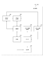
- FIG. 1 is a diagram illustrating an example of an overall configuration of a communication system according to an embodiment of the present technology.
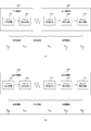
- FIG. 2 is a diagram illustrating a configuration example of output devices 101 and 102 according to the embodiment of the present technology.
- Fig. 3 is a diagram illustrating an example of processing contents of output devices 101 and 102 according to the embodiment of the present technology.
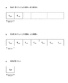
- Fig. 3 is a diagram illustrating a field configuration example of a time measurement packet and a time setting packet according to the embodiment of the present technology.
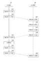
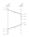
- FIG. 9 is a sequence diagram illustrating an example of a processing flow between an output device A (101) and an output device B (102) according to the embodiment of the present technology.
- FIG. 3 is a diagram illustrating a protocol stack in BLE.
- FIG. 3 is a diagram illustrating a packet structure of a link layer in BLE.
- FIG. 21 is a sequence diagram illustrating an example of a processing flow in an application example of the embodiment of the present technology to BLE.
- Embodiment 2 a mode for implementing the present technology (hereinafter, referred to as an embodiment) will be described. The description will be made in the following order. 1. Embodiment 2. Application example
- FIG. 1 is a diagram illustrating an example of an overall configuration of a communication system according to an embodiment of the present technology. Here, two output devices A (101) and two output devices B (102) and an operation device 300 are shown.
- the output device A (101) and the output device B (102) are devices that output according to an operation from the operation device 300.
- audio devices such as headphones and speakers are assumed.
- the output device A (101) reproduces and outputs the left channel audio
- the output device B (102) reproduces and outputs the right channel audio.
- the output device A (101) and the output device B (102) may be collectively referred to as output devices 101 and 102.
- the operation device 300 is a device for performing operations on the output devices 101 and 102. Signals (operation signals and audio signals) from the operation device 300 to the output devices 101 and 102 are transmitted by wireless communication.
- the exchange between the output device A (101) and the output device B (102) is also performed by wireless communication. As these wireless communications, for example, those utilizing the BLE standard are assumed. An example of applying the present technology to the BLE standard will be separately described later.
- the operation device 300 transmits the left channel and right channel audio signals to the output devices 101 and 102, respectively.
- Each of the output devices 101 and 102 reproduces the audio signals of the left channel and the right channel, respectively.
- Each of the output devices 101 and 102 has its own clock, and reproduces an audio signal according to the clock. Therefore, if there is a difference between the clocks of the output devices 101 and 102, there will be a difference in the reproduction output, giving a sense of incongruity to the listener.
- the clock is synchronized between the output device A (101) and the output device B (102), and the reproduction output is performed while suppressing the shift in the time axis direction.
- FIG. 2 is a diagram illustrating a configuration example of the output devices 101 and 102 according to the embodiment of the present technology.
- clock synchronization between devices includes a frequency component and a phase component.
- the phase component will be considered.
- the output devices 101 and 102 include an RF unit 110, a communication unit 120, a packet generation unit 130, a packet analysis unit 140, a clock 150, a clock information acquisition unit 160, a clock information correction unit 170, an output unit 190.
- the RF (Radio Frequency) unit 110 is a circuit that handles the high frequency of wireless communication.
- the RF unit 110 demodulates the received signal to generate a baseband signal, or modulates the baseband signal and transmits it.
- the communication unit 120 performs communication according to a protocol according to a communication method.
- the communication unit 120 performs communication through a GATT connection according to a procedure defined in the BLE standard, for example.
- the packet generator 130 generates a packet for performing wireless communication.
- the packet generation unit 130 generates, for example, a GATT packet defined by the BLE standard.
- the packet generation unit 130 is an example of a time adjustment instruction unit described in the claims.
- the packet analysis unit 140 analyzes a received packet and performs necessary processing.
- the packet analysis unit 140 extracts, for example, a specific field of a GATT packet defined in the BLE standard.
- the packet analysis unit 140 generates a time difference based on the time stored in the packet received from the outside as described later.
- the packet analysis unit 140 is an example of a time difference generation unit described in the claims.
- the clock 150 is a circuit that generates a periodic signal. Each unit of the output devices 101 and 102 performs each operation in synchronization with the periodic signal generated by the clock 150.
- the periodic signal itself or a time converted signal is used as time. That is, the clock 150 is an example of a time management unit that manages the time described in the claims.
- the clock information acquisition unit 160 acquires the value of the clock 150 and supplies the value to the packet generation unit 130.
- the packet generator 130 stores the value of the clock 150 in the packet as the time, as described later. Note that the clock information acquisition unit 160 is an example of a time measurement unit described in the claims.
- the clock information correction unit 170 corrects the value of the clock 150.
- the clock information correction unit 170 corrects the value of the clock 150 based on the time difference generated by the packet analysis unit 140. Note that the clock information correction unit 170 is an example of a time correction unit described in the claims.
- the output unit 190 reproduces and outputs the supplied audio signal in synchronization with the value of the clock 150. If the clocks 150 of the output devices 101 and 102 are correctly synchronized with each other, the output unit 190 can also perform reproduction output without occurrence of a shift.
- FIG. 3 is a diagram illustrating an example of the processing content of the output devices 101 and 102 according to the embodiment of the present technology.
- a indicates the processing content when a packet is transmitted from the output device A (101) to the output device B (102).
- the output device A (101) performs a packet generation process 131 and performs a transmission process 121 of the generated packet.
- the time when the packet is generated by the packet generation processing 131 is represented by t sgp
- the time when the packet is transmitted by the packet transmission processing 121 is represented by t ssp . That is, the processing delay of the output device A (101) required from the generation of the packet to the transmission of the packet is calculated as “t ssp ⁇ t sgp ”.
- the output device B (102) performs the receiving process 112 of the packet from the output device A (101), and performs the analyzing process 142 of the received packet. Then, a correction process 172 of the value of the clock 150 is performed as necessary.
- t crp the time at which the packet was received by the packet reception processing 112
- t cap the time at which the packet was analyzed by the packet analysis processing 142 to generate a value for correction.
- the time at which the value of the clock 150 is set by the clock correction processing 172 is defined as t csc .
- the transmission delay required from when the packet is transmitted by the output device A (101) to when it is received by the output device B (102) is calculated as “t crp ⁇ t ssp ”.
- the processing delay of the output device B (102) required from when the packet is received until the value of the clock 150 is set is calculated as “t csc ⁇ t crp ”.
- “B” in the figure indicates the processing content when a packet is transmitted from the output device B (102) to the output device A (101).
- the output device B (102) performs a packet generation process 132 and performs a transmission process 122 of the generated packet.
- the time at which the packet was generated by the packet generation process 132 is represented by t cgp
- the time at which the packet was transmitted by the packet transmission process 122 is represented by t csp . That is, the processing delay of the output device B (102) required from the generation of the packet to the transmission of the packet is calculated as “t csp ⁇ t cgp ”.
- the output device A (101) performs the receiving process 111 of the packet from the output device B (102), and performs the analyzing process 141 of the received packet. Then, a correction process 171 of the value of the clock 150 is performed as necessary.
- the time at which the packet was received by the packet receiving process 111 is represented by t srp
- the time at which the packet was analyzed by the packet analyzing process 141 to generate a value for correction is represented by t sap .
- the time at which the value of the clock 150 is set by the clock correction processing 171 is represented by t ssc .
- the transmission delay required from when the packet is transmitted by the output device B (102) to when it is received by the output device A (101) is calculated as “t srp -t csp ".
- the processing delay of the output device A (101) required from when the packet is received until the value of the clock 150 is set is calculated as “t ssc ⁇ t srp ”.
- FIG. 4 is a diagram illustrating a field configuration example of a time measurement packet and a time setting packet according to the embodiment of the present technology.
- the output device A (101) transmits a time measurement packet to the output device B (102) in order to generate a time difference of the clock 150 between the output device A (101) and the output device B (102).
- the time measurement packet is a packet that stores the value of the clock 150 of the output device 101 or 102 for each process as a time stamp (time) in the course of communication between the output devices 101 and 102.
- the time measurement packet stores each time as 32-bit data.
- a indicates the state of the time measurement packet when transmitted from the output device A (101) to the output device B (102).
- the output device A (101) stores the time t sgp at which the packet was generated and the time t ssp at which the packet was transmitted in a time measurement packet, and transmits the packet to the output device B (102).
- the time measurement packet is received by the output device B (102), and each time is stored in the time measurement packet as the processing proceeds. Then, the time measurement packet is transmitted to the output device A (101).
- “B” in the figure shows the state of the time measurement packet when transmitted from the output device B (102) to the output device A (101).
- the output device B (102) transmits the packet at time t crp , the packet analysis time t cap , the time t csc at which the value of the clock 150 is set, the time t cgp at which the packet was generated, and the packet.
- the time t csp stored in the time measurement packet is transmitted to the output device A (101).
- the time measurement packet is analyzed by the output device A (101), and the output device A (101) generates the set value t diff based on the time difference of the clock 150 between the output device A (101) and the output device B (102). .
- c indicates the state of the time setting packet when transmitted from the output device A (101) to the output device B (102).
- This time setting packet is a packet indicating a value t diff set to the clock 150 of the output device B (102).
- the time setting packet stores the value t diff as 32-bit data.
- the output device B (102) that has received the time setting packet sets the setting value t diff stored in the time setting packet to the clock 150.
- the clock 150 is synchronized between the output device A (101) and the output device B (102).
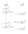
- FIG. 5 is a sequence diagram illustrating an example of a processing flow between the output device A (101) and the output device B (102) according to the embodiment of the present technology.
- the output device A (101) generates a time measurement packet (step S811) and transmits it to the output device B (102) (step S812).
- the output device B (102) receives the time measurement packet (Step S821) and measures the reception time. After analyzing the time measurement packet (step S822), the output device B (102) adds the reception time to the time measurement packet, adds the transmission time immediately before transmission (step S823), and outputs the output device A (101). ) (Step S824).
- the output device A (101) receives the time measurement packet returned from the output device B (102) (step S815), and analyzes the time measurement packet. That is, the time measurement packet is reciprocated while recording the time stamp of each obtainable processing time, and all the information is collected in the output device A (101).
- the output device A (101) calculates the processing delay time in the output device A (101) and the output device B (102) and the transmission delay time between them, and outputs the clock 150 of the output device B (102). Is calculated (step S816).
- the output device A (101) generates a time setting packet that stores the calculated set value (step S817), and transmits it to the output device B (102) (step S818).
- the output device B (102) receives the time setting packet (step S829), and sets the stored setting value in the clock 150.
- FIG. 6 is a diagram illustrating a specific example of the time in the output device A (101) and the output device B (102) according to the embodiment of the present technology. As described above, in this embodiment, the time stamp of each available processing point is recorded by reciprocating the time measurement packet.
- the time t sgp at which the time measurement packet is generated in the output device A (101) is “110”, and the time t ssp at which the time measurement packet is transmitted is “140”.
- the output device A (101) transmits a time measurement packet storing these two times t sgp and t ssp to the output device B (102).
- the output device B (102) receives the time measurement packet transmitted from the output device A (101). At this time, the output device B (102) is operating at a different time from the output device A (101). In this example, it is assumed that the time t crp at which the time measurement packet is received by the output device B (102) is “1000”. It is also assumed that the analysis time t cap of the time measurement packet is “1050”, and the time t csc at which the value of the clock 150 is set is “1120”.
- the output device A (101) receives the time measurement packet returned from the output device B (102).
- the time t srp at which the time measurement packet is received by the output device A (101) is “860”. It is also assumed that the analysis time t sap of the time measurement packet is “910”, and the time t ssc when passing through the routine for setting the value of the clock 150 is “980”.
- the processing delay is "30" from packet generation to transmission and "120" from packet reception to clock setting. From this approximation, it can be assured that the output device A (101) and the output device B (102) can be calculated using the same model.
- the time setting packet is transmitted to synchronize the clock of the output device B (102) with the output device A (101). Conversely, the clock of the output device A (101) is changed to the output device A (101). B (102). In this case, there is no need to transmit a time setting packet, and the output device A (101) sets the clock time.
- FIG. 7 is a diagram showing a communication procedure in BLE.
- Communications occurring in the physical channel of the BLE standard include advertising (Advertising) communication for broadcasting and connection communication between two devices performed in a state where a connection (connection) is established with a specific device.
- Advertising communication is data transmission using an advertising channel.
- the advertising communication starts when one device (advertiser) transmits an advertising packet using an advertising channel.
- the other device goes around the advertising channel and receives the advertising packet.
- Connection communication is communication for transmitting and receiving data between the master and the slave.
- the connection communication starts when the master transmits a packet (frame) to the slave via the data channel, and thereafter, the master and the slave alternately transmit data.
- the output device B (102) is an advertiser, and always transmits an advertising packet (ADV_IND: Advertising @Indication) at predetermined intervals to accept a GATT connection request.
- the output device A (101) is a scanner, and returns a communication request packet (CONNECT_REQ: Connection @ Request) for requesting a GATT connection by using an advertising channel. This starts the connection. Note that a state until the connection is started is called an advertising state, and one-way communication by GAP (Generic Access Profile) is performed.
- GAP Generic Access Profile
- connection After the connection is established, it is called a connected state, and bidirectional communication is performed through a GATT connection.
- the output device A (101) becomes a master
- the output device B (102) becomes a slave.
- a frame (TERMINATE) for leaving the connected state can be transmitted from either the master or the slave.
- the output device A (101) is assumed to be the master, and the output device B (102) is assumed to be the slave.
- a master may be determined in advance by negotiation.
- a master device may be given priority to a right channel output device or a left channel output device. Alternatively, it may be determined that the one who made the connection request first becomes the master.
- FIG. 8 is a diagram showing a protocol stack in BLE.
- GATT structures data using ATT (ATTribute @ profile). GATT communicates with applications. In the GATT connection, it is possible to perform information distribution using a GATT characteristic (Characteristic). GATT provides a characteristic for each of one or more services on a server. The necessary processing is performed by writing or reading the value of the characteristic from the client. As the characteristic of the GATT profile, a uniquely defined characteristic may be used.
- SMP Security Manager Protocol
- L2CAP Logical Link Control and Adaptation Protocol
- GAP GAP
- HCI Home Controller Interface
- the controller is divided into a physical layer for performing physical communication and a link layer for controlling the physical layer.
- FIG. 9 is a diagram showing a packet structure of a link layer in BLE. In this embodiment, an asynchronous packet is shown on the assumption that asynchronous communication is performed in a GATT connection.
- connection is made intermittently.
- the transmission interval is defined as a connInterval value in the standard, and a value between 7.5 ms and 4.0 s is set in 1.25 ms steps.
- the $ connInterval is divided into a plurality of sub-events, and communication from the master to the slave and communication from the slave to the master are performed in one sub-event.
- the period between the communication from the master to the slave and the communication from the slave to the master is defined by the T_IFS value in the standard. Also, a period between the communication from the slave to the master and the end of the sub-event needs to secure a period longer than the T_MSS value according to the standard.
- the link layer packet used for communication from the master to the slave includes a 1-byte or 2-byte preamble, a 4-byte access address, a 2- to 257-byte PDU, a 4-byte MIC, and a 3-byte CRC.
- the preamble is a bit string used for detecting the timing in bit units on the receiving side.
- the access address is an address of a transmission destination to be accessed. In BLE, a random value is assigned to this access address for each connection between devices.
- PDU Protocol @ Data @ Unit
- MIC Message ⁇ Integrity ⁇ Check
- CRC Cyclic ⁇ Redundancy ⁇ Check
- CRC Cyclic ⁇ Redundancy ⁇ Check
- $ PDU is composed of 2-bit LLID, 1-bit NESN, 1-bit SN, 1-bit MD, 3-bit RFU, 8-bit Length, and payload of 1 to 255 bytes.
- LLID Logical Link ID
- NESN Next ⁇ Expected ⁇ Sequence ⁇ Number
- SN Sequence @ Number
- MD Merase @ Data
- RFU Reserved @ for @ Future @ Use
- Length is information indicating the length in bytes of the payload plus the MIC.
- the payload is data transmitted by the PDU. What connects the payload of this PDU according to the sequence number constitutes various data in the GATT connection.
- FIG. 10 is a sequence diagram illustrating an example of a processing flow in an example in which the embodiment of the present technology is applied to the BLE.
- GATT communicates according to a server-client model.
- the side providing the function is called a GATT server, and the side using the function is called a GATT client.
- the output device A (101) is a GATT client
- the output device B (102) is a GATT server.
- the GATT server has a data structure that combines profile service characteristics. In GATT data communication, access is performed by designating a handle (data position) of the data structure.
- the GATT data communication starts (step S711).
- the GATT client needs to know the handle to each definition data of the data structure of the GATT server. Reading of the data structure is divided into two stages, whereby the association between the UUID and the handle is obtained. That is, as a first step, a service used by the client is searched, and then, as a second step, characteristic definition information of the service is searched. The actual data access of the characteristic uses the handle of the read information to access a predetermined position of the GATT server.
- the output device A (101) transmits the above-described time measurement packet to the output device B (102) by a write request (step S712). At this time, the output device A (101) creates a database of the time measurement GATT, and manages the time measurement packet with the attribute.
- the read / write API corresponds to GATTM_ATT_SET_VALUE_REQ data.
- the output device B (102) receives the time measurement packet and performs a write process (step S723). That is, the time for each process of the output device B (102) is stored in the received time measurement packet.
- the output device B (102) transmits the time measurement packet to the output device A (101) (Step S724).
- the GATT communication there are a notification in which a server notifies a client and a response to the notification is not required, and an indication in which a confirmation response is required. Since the time measurement packet from the output device B (102) in this embodiment does not require a response, a notification is used.
- the output device A (101) receives the time measurement packet (step S715), calculates the processing delay and the transmission delay from the time stored in the time measurement packet as described above, and outputs the output device B (102). Generates clock settings. Then, the above-mentioned time setting packet is transmitted to the output device B (102) by a write request (step S716). At this time, the output device A (101) creates a database of the time setting GATT, and manages the time setting packet with the attribute.
- the read / write API corresponds to GATTM_ATT_SET_VALUE_REQ data.
- the output device B (102) receives the time setting packet, and sets its own clock in accordance with the packet (step S727).
- the devices send each other packets, the one sent later has priority. If the time measurement packet is received during the processing of the time measurement packet, the time measurement packet is filled with zeros and the overlap is notified to the partner device. The device receiving this resends the time with a random value. If the output device B (102) receives the time setting packet before the time measurement packet, the output device B (102) does not process the time setting packet.
- synchronization is performed between the output devices 101 and 102 connected via communication by collecting the time for each process and generating a time difference between clocks.
- a time difference can be generated across a disconnection, so that synchronization can be performed while flexibly responding to a change in communication state.
- an audio device that reproduces and outputs stereo sound is assumed.
- the present invention is not limited to this.
- a video device that reproduces and outputs a stereo image may be used.
- the present invention is not limited to the left and right stereo outputs, and can be applied to general synchronization processing between devices.
- the processing procedure described in the above-described embodiment may be regarded as a method having these series of procedures, or a program for causing a computer to execute these series of procedures or a recording medium storing the program. May be caught.
- a recording medium for example, a CD (Compact Disc), an MD (MiniDisc), a DVD (Digital Versatile Disc), a memory card, a Blu-ray Disc (Blu-ray (registered trademark) Disc), or the like can be used.
- the present technology may have the following configurations.
- the communication device as described.
- the time measurement unit measures the time of the process before transmission to the other device and the time of the internal process after reception by the other device as the predetermined process.
- the communication device according to any one of 3).
- the time correction instructing unit transmits a time setting packet for setting the time of the another time management unit to a designated time to the other device.
- the time adjustment instructing unit delays time required for processing before transmission to the other device, communication with the other device, and internal processing after reception in the other device.
- the communication device according to any one of (1) to (5), wherein, as the time, a time obtained by reflecting the delay time on the time of the time management unit is set as the time of the another time management unit.
- the communication device according to any one of (1) to (6), further including an output unit that performs a predetermined output according to the time of the time management unit.
- the communication device according to any one of (1) to (7), wherein the communication is performed by a communication method that allows intermittent connection.
- the communication is performed in accordance with the wireless communication standard Bluetooth (registered trademark) Low Energy
- the time measurement unit transmits and receives a packet for measuring the time of the other time management unit and the time of the time management unit through a GATT (Generic ATTribute profile) connection
- the communication device according to (8), wherein the time adjustment instructing unit transmits a packet instructing the other time management unit to adjust the time by a GATT connection.
- a time management unit for managing time (10) a time management unit for managing time; A time measurement unit that measures the time of the other time management unit and the time of the time management unit for each predetermined process in a communication process with another device having another time management unit, A time difference generation unit that generates a time difference between the time of the other time management unit and the time of the time management unit based on the measured time, A communication device comprising: a time correction unit configured to correct the time of the time management unit based on the generated time difference.
- a communication system including first and second communication devices each including a time management unit that manages time
- the first communication device includes: A time measurement unit that measures the time of the time management unit of the second communication device and the time of the time management unit of the first communication device in a process of communication with the second communication device for each predetermined process; When, A time difference generation unit that generates a time difference between the time of the time management unit of the second communication device and the time of the time management unit of the first communication device based on the measured time; A time correction instruction unit that instructs the other device to correct the time of the time management unit of the second communication device based on the generated time difference,
- the communication system wherein the second communication device corrects a time of a time management unit of the second communication device according to an instruction from the time correction instruction unit of the first communication device.
Landscapes
- Engineering & Computer Science (AREA)
- Computer Networks & Wireless Communication (AREA)
- Signal Processing (AREA)
- Physics & Mathematics (AREA)
- General Physics & Mathematics (AREA)
- Synchronisation In Digital Transmission Systems (AREA)
Abstract
通信を介して接続する複数の通信装置間において、通信状態の変化に柔軟に対応しながら同期を行う。 時刻管理部は、時刻を管理する。時刻計測部は、他の時刻管理部を有する他の装置との通信の過程において、他の時刻管理部の時刻とこの装置の時刻管理部の時刻とをそれぞれ所定の処理毎に計測する。時刻差生成部は、計測された時刻に基づいて、他の時刻管理部の時刻と時刻管理部の時刻との時刻差を生成する。時刻修正指示部は、生成された時刻差に基づいて、他の装置に対して他の時刻管理部の時刻の修正を指示する。
Description
本技術は、通信システムに関する。詳しくは、通信を介して接続する複数の通信装置が互いに同期する通信システム、および、その通信システムにおける通信装置に関する。
従来、通信を複数の機器間で同期をするために、予め固定された時間だけ一方の出力を遅延させる技術が知られている。例えば、ステレオペア設定されたオーディオ機器において、パワーアンプへの出力を通信遅延時間だけ遅延させることにより、ペアとなる他のオーディオ機器との再生を同期させるオーディオ機器が提案されている(例えば、特許文献1参照。)。
上述の従来技術では、遅延時間として、オーディオ再生における他のオーディオ機器との通信遅延時間を予め設定しておく必要がある。そのため、通信状態に変化が生じると対応できなくなるという問題がある。また、近年では省電力のために断続的接続を許容する通信方式が提案されており、通信遅延時間を一律に設定することは困難である。
本技術はこのような状況に鑑みて生み出されたものであり、通信を介して接続する複数の通信装置間において、通信状態の変化に柔軟に対応しながら同期を行うことを目的とする。
本技術は、上述の問題点を解消するためになされたものであり、その第1の側面は、時刻を管理する時刻管理部と、他の時刻管理部を有する他の装置との通信の過程において上記他の時刻管理部の時刻と上記時刻管理部の時刻とをそれぞれ所定の処理毎に計測する時刻計測部と、上記計測された時刻に基づいて上記他の時刻管理部の時刻と上記時刻管理部の時刻との時刻差を生成する時刻差生成部と、上記生成された時刻差に基づいて上記他の装置に対して上記他の時刻管理部の時刻の修正を指示する時刻修正指示部とを具備する通信装置および通信システムである。これにより、計測された時刻に基づいて時刻差を生成して、その時刻差に基づいて他の装置の時刻を修正させて、装置間の同期をとるという作用をもたらす。
また、この第1の側面において、上記時刻計測部は、上記所定の処理毎の上記他の時刻管理部の時刻および上記時刻管理部の時刻を取得して格納する時刻計測パケットを送受信するようにしてもよい。これにより、時刻計測パケットにより処理毎の時刻を収集するという作用をもたらす。
また、この第1の側面において、上記時刻計測部は、上記所定の処理として、上記他の装置への送信、および、上記他の装置における送受信が行われた際の時刻を計測するようにしてもよい。これにより、各装置における送受信の際の時刻を計測するという作用をもたらす。
また、この第1の側面において、上記時刻計測部は、上記所定の処理として、上記他の装置に送信を行う前の処理、および、上記他の装置における受信後の内部処理の時刻を計測するようにしてもよい。これにより、各装置における内部処理の際の時刻を計測するという作用をもたらす。
また、この第1の側面において、上記時刻修正指示部は、指定した時刻に上記他の時刻管理部の時刻を設定させる時刻設定パケットを上記他の装置に対して送信するようにしてもよい。これにより、他の装置の時刻を設定させて、装置間の同期をとるという作用をもたらす。
また、この第1の側面において、上記時刻修正指示部は、上記他の装置に送信を行う前の処理、上記他の装置との間の通信、および、上記他の装置における受信後の内部処理に要した時間を遅延時間として、上記時刻管理部の時刻に上記遅延時間分を反映させた時刻を上記他の時刻管理部の時刻に設定させるようにしてもよい。これにより、遅延時間分を反映させた時刻を他の装置の時刻として設定させて、装置間の同期をとるという作用をもたらす。
また、この第1の側面において、上記時刻管理部の時刻に従って所定の出力を行う出力部をさらに具備してもよい。これにより、各装置からの出力を同期させるという作用をもたらす。
また、この第1の側面において、上記通信は、断続的接続を許容する通信方式により行われるようにしてもよい。処理毎の時刻を収集することにより、断続的接続に対しても対応可能である。例えば、無線通信規格Bluetooth(登録商標) Low Energy(以下、BLEと称する。)に準拠して行われ、上記時刻計測部は、GATT(Generic ATTribute profile)接続によって上記他の時刻管理部の時刻および上記時刻管理部の時刻を計測するパケットを送受信し、上記時刻修正指示部は、GATT接続によって上記他の時刻管理部の時刻の修正を指示するパケットを送信するようにしてもよい。
また、本技術の第2の側面は、時刻を管理する時刻管理部と、他の時刻管理部を有する他の装置との通信過程において上記他の時刻管理部の時刻と上記時刻管理部の時刻とをそれぞれ所定の処理毎に計測する時刻計測部と、上記計測された時刻に基づいて上記他の時刻管理部の時刻と上記時刻管理部の時刻との時刻差を生成する時刻差生成部と、上記生成された時刻差に基づいて上記時刻管理部の時刻を修正する時刻修正部とを具備する通信装置および通信システムである。これにより、計測された時刻に基づいて時刻差を生成して、その時刻差に基づいて自装置の時刻を修正して、装置間の同期をとるという作用をもたらす。
以下、本技術を実施するための形態(以下、実施の形態と称する)について説明する。説明は以下の順序により行う。
1.実施の形態
2.適用例
1.実施の形態
2.適用例
<1.実施の形態>
[通信システム]
図1は、本技術の実施の形態における通信システムの全体構成の例を示す図である。ここでは、2台の出力機器A(101)および出力機器B(102)と、操作機器300とを示している。
[通信システム]
図1は、本技術の実施の形態における通信システムの全体構成の例を示す図である。ここでは、2台の出力機器A(101)および出力機器B(102)と、操作機器300とを示している。
出力機器A(101)および出力機器B(102)は、操作機器300からの操作に従って、出力を行う機器である。例えば、ヘッドホンやスピーカなどのオーディオ機器が想定される。この場合、出力機器A(101)は左チャンネルの音声を再生出力し、出力機器B(102)は右チャンネルの音声を再生出力する。なお、以下では、出力機器A(101)および出力機器B(102)をまとめて、出力機器101および102と称する場合がある。
操作機器300は、出力機器101および102に対する操作を行うための機器である。操作機器300から出力機器101および102への信号(操作信号および音声信号)は、無線通信により送信される。また、出力機器A(101)と出力機器B(102)との間のやりとりも無線通信により行われる。これらの無線通信としては、例えば、BLE規格を利用したものが想定される。なお、本技術のBLE規格への適用例については、別途後述する。
操作機器300は、出力機器101および102に左チャンネルおよび右チャンネルの音声信号をそれぞれ送信する。出力機器101および102の各々は、それぞれ左チャンネルおよび右チャンネルの音声信号を再生する。出力機器101および102は、それぞれ自身のクロックを備えており、そのクロックに従って音声信号の再生を行う。したがって、出力機器101および102のクロックにずれがあると、再生出力にずれを生じて、聴取者に対して聴覚上の違和感を与えることになる。この実施の形態では、出力機器A(101)と出力機器B(102)との間でクロックを同期させて、時間軸方向のずれを抑えながら再生出力を行う。
[出力機器]
図2は、本技術の実施の形態における出力機器101および102の構成例を示す図である。
図2は、本技術の実施の形態における出力機器101および102の構成例を示す図である。
出力機器101および102は、同一の構成を有する機器であると想定する。したがって、出力機器101および102におけるパケットの送信および受信に要する処理時間はそれぞれ同じである、とモデル化する。また、出力機器A(101)と出力機器B(102)との間の伝送時間は、同じパケット長であれば、上りと下り(往路と復路)において同じ時間を要するものと仮定する。なお、一般に、機器間のクロックの同期には周波数成分と位相成分とがあるが、ここでは位相成分について検討する。
出力機器101および102はそれぞれ、RF部110と、通信部120と、パケット生成部130と、パケット解析部140と、クロック150と、クロック情報取得部160と、クロック情報補正部170と、出力部190とを備える。
RF(Radio Frequency)部110は、無線通信の高周波を扱う回路である。このRF部110は、受信した信号を復調してベースバンド信号を生成し、または、ベースバンド信号を変調して送信する。
通信部120は、通信方式に従ったプロトコルにより通信を行うものである。この通信部120は、例えば、BLE規格に定められた手順によりGATT接続による通信を行う。
パケット生成部130は、無線通信を行うためのパケットを生成するものである。このパケット生成部130は、例えば、BLE規格に定められたGATTパケットを生成する。なお、パケット生成部130は、特許請求の範囲に記載の時刻修正指示部の一例である。
パケット解析部140は、受信したパケットを解析して必要な処理を行うものである。このパケット解析部140は、例えば、BLE規格に定められたGATTパケットの特定のフィールドを抽出する。また、このパケット解析部140は、後述するように外部から受信したパケットに格納されている時刻に基づいて時刻差を生成する。なお、パケット解析部140は、特許請求の範囲に記載の時刻差生成部の一例である。
クロック150は、周期信号を生成する回路である。出力機器101および102の各部は、このクロック150が生成する周期信号に同期してそれぞれの動作を行う。以下では、この周期信号そのもの、または、時間換算したものを、時刻として用いる。すなわち、クロック150は、特許請求の範囲に記載の時刻を管理する時刻管理部の一例である。
クロック情報取得部160は、クロック150の値を取得してパケット生成部130に供給するものである。パケット生成部130は、後述するようにクロック150の値を時刻としてパケットに格納する。なお、クロック情報取得部160は、特許請求の範囲に記載の時刻計測部の一例である。
クロック情報補正部170は、クロック150の値を補正するものである。このクロック情報補正部170は、パケット解析部140によって生成された時刻差によってクロック150の値を補正する。なお、クロック情報補正部170は、特許請求の範囲に記載の時刻修正部の一例である。
出力部190は、クロック150の値に同期して、供給された音声信号の再生出力を行うものである。出力機器101および102のそれぞれのクロック150同士が正しく同期されていれば、この出力部190もずれを生じることなく再生出力を行うことができる。
図3は、本技術の実施の形態における出力機器101および102の処理内容の例を示す図である。
同図におけるaは、出力機器A(101)から出力機器B(102)にパケットを送信する場合の処理内容を示している。出力機器A(101)は、パケット生成処理131を行い、生成されたパケットの送出処理121を行う。ここで、パケット生成処理131によってパケットが生成された時刻をtsgpとし、パケット送出処理121によってパケットが送出された時刻をtsspとする。すなわち、パケットが生成されてからパケットが送出されるまでに要する出力機器A(101)の処理遅延は「tssp-tsgp」として算出される。
出力機器B(102)は、出力機器A(101)からのパケットの受信処理112を行い、受信したパケットの解析処理142を行う。そして、必要に応じてクロック150の値の補正処理172を行う。ここで、パケットの受信処理112によってパケットを受信した時刻をtcrpとし、パケット解析処理142によってパケットを解析して補正のための値を生成した時刻をtcapとする。また、クロック補正処理172によってクロック150の値を設定した時刻をtcscとする。すなわち、パケットが出力機器A(101)によって送出されてから出力機器B(102)によって受信されるまでに要する伝送遅延は「tcrp-tssp」として算出される。また、パケットが受信されてからクロック150の値が設定されるまでに要する出力機器B(102)の処理遅延は「tcsc-tcrp」として算出される。
同図におけるbは、出力機器B(102)から出力機器A(101)にパケットを送信する場合の処理内容を示している。出力機器B(102)は、パケット生成処理132を行い、生成されたパケットの送出処理122を行う。ここで、パケット生成処理132によってパケットが生成された時刻をtcgpとし、パケット送出処理122によってパケットが送出された時刻をtcspとする。すなわち、パケットが生成されてからパケットが送出されるまでに要する出力機器B(102)の処理遅延は「tcsp-tcgp」として算出される。
出力機器A(101)は、出力機器B(102)からのパケットの受信処理111を行い、受信したパケットの解析処理141を行う。そして、必要に応じてクロック150の値の補正処理171を行う。ここで、パケットの受信処理111によってパケットを受信した時刻をtsrpとし、パケット解析処理141によってパケットを解析して補正のための値を生成した時刻をtsapとする。また、クロック補正処理171によってクロック150の値を設定した時刻をtsscとする。すなわち、パケットが出力機器B(102)によって送出されてから出力機器A(101)によって受信されるまでに要する伝送遅延は「tsrp-tcsp」として算出される。また、パケットが受信されてからクロック150の値が設定されるまでに要する出力機器A(101)の処理遅延は「tssc-tsrp」として算出される。
上述のように、出力機器A(101)および出力機器B(102)は同一の構成を有しており、対応する処理遅延は等しいものと想定する。また、伝送遅延についても等しいものと想定する。すなわち、
tssp-tsgp=tcsp-tcgp
tcrp-tssp=tsrp-tcsp
tcsc-tcrp=tssc-tsrp
の関係を有する。
tssp-tsgp=tcsp-tcgp
tcrp-tssp=tsrp-tcsp
tcsc-tcrp=tssc-tsrp
の関係を有する。
なお、何らかの通信障害によって伝送遅延が伸びた場合でも、送受信の両者で同程度の伸びが生じたのであれば、上の関係は成立する。
[パケット構成]
図4は、本技術の実施の形態における時刻計測パケットおよび時刻設定パケットのフィールド構成例を示す図である。
図4は、本技術の実施の形態における時刻計測パケットおよび時刻設定パケットのフィールド構成例を示す図である。
出力機器A(101)は、出力機器B(102)との間のクロック150の時刻差を生成するために、時刻計測パケットを出力機器B(102)に送信する。この時刻計測パケットは、出力機器101および102の間の通信の過程において、処理毎の出力機器101または102のクロック150の値をタイムスタンプ(時刻)として格納するパケットである。なお、この例では、時刻計測パケットは、各々の時刻を32ビットデータとして格納する。
同図におけるaは、出力機器A(101)から出力機器B(102)に送信される際の時刻計測パケットの状態を示している。出力機器A(101)は、パケットが生成された時刻tsgp、および、パケットが送出された時刻tsspを時刻計測パケットに格納して、出力機器B(102)に送信する。
その後、時刻計測パケットは出力機器B(102)によって受信され、処理が進むに従って各時刻が時刻計測パケットに格納されていく。そして、この時刻計測パケットは出力機器A(101)に送信される。
同図におけるbは、出力機器B(102)から出力機器A(101)に送信される際の時刻計測パケットの状態を示している。出力機器B(102)は、パケットを受信した時刻tcrp、パケットを解析した時刻tcap、クロック150の値を設定した時刻tcsc、パケットが生成された時刻tcgp、および、パケットが送出された時刻tcspを時刻計測パケットに格納して、出力機器A(101)に送信する。
その後、時刻計測パケットは出力機器A(101)によって解析され、出力機器A(101)は、出力機器B(102)との間のクロック150の時刻差に基づいて設定値tdiffが生成される。
同図におけるcは、出力機器A(101)から出力機器B(102)に送信される際の時刻設定パケットの状態を示している。この時刻設定パケットは、出力機器B(102)のクロック150に設定される値tdiffを指示するパケットである。なお、この例では、時刻設定パケットは、値tdiffを32ビットデータとして格納する。
この時刻設定パケットを受信した出力機器B(102)は、時刻設定パケットに格納される設定値tdiffをクロック150に設定する。これにより、出力機器A(101)と出力機器B(102)との間でクロック150が同期される。
[動作]
図5は、本技術の実施の形態における出力機器A(101)と出力機器B(102)との間の処理の流れの一例を示すシーケンス図である。
図5は、本技術の実施の形態における出力機器A(101)と出力機器B(102)との間の処理の流れの一例を示すシーケンス図である。
出力機器A(101)は、時刻計測パケットを生成して(ステップS811)、出力機器B(102)に送信する(ステップS812)。
出力機器B(102)は、時刻計測パケットを受信して(ステップS821)、受信時刻を測定する。出力機器B(102)は、時刻計測パケットを解析した後(ステップS822)、受信時刻を時刻計測パケットに追加し、送信する直前に送信時刻を追加して(ステップS823)、出力機器A(101)に送信する(ステップS824)。
出力機器A(101)は、出力機器B(102)から返信された時刻計測パケットを受信して(ステップS815)、その時刻計測パケットを解析する。すなわち、各々の取得可能な処理時点のタイムスタンプを記録しながら時刻計測パケットを往復させて、全ての情報を出力機器A(101)に集約させる。
これにより、出力機器A(101)は、出力機器A(101)および出力機器B(102)における処理遅延時間、および、両者間の伝送遅延時間を算出し、出力機器B(102)のクロック150の設定値を算出する(ステップS816)。出力機器A(101)は、算出した設定値を格納した時刻設定パケットを生成し(ステップS817)、出力機器B(102)に送信する(ステップS818)。
出力機器B(102)は、時刻設定パケットを受信して(ステップS829)、格納されている設定値をクロック150に設定する。
[具体例]
図6は、本技術の実施の形態の出力機器A(101)および出力機器B(102)における時刻の具体例を示す図である。上述のように、この実施の形態においては、時刻計測パケットを往復させることにより、各々の取得可能な処理時点のタイムスタンプを記録する。
図6は、本技術の実施の形態の出力機器A(101)および出力機器B(102)における時刻の具体例を示す図である。上述のように、この実施の形態においては、時刻計測パケットを往復させることにより、各々の取得可能な処理時点のタイムスタンプを記録する。
この例では、出力機器A(101)において時刻計測パケットが生成された時刻tsgpは「110」であり、時刻計測パケットが送出された時刻tsspは「140」であったものとする。出力機器A(101)は、これら2つの時刻tsgpおよびtsspを格納した時刻計測パケットを出力機器B(102)に送信する。
出力機器B(102)は、出力機器A(101)から送信された時刻計測パケットを受信する。この時点においては、出力機器B(102)は出力機器A(101)とは異なる時刻により動作している。この例では、出力機器B(102)において時刻計測パケットが受信された時刻tcrpは「1000」であったものとする。また、時刻計測パケットの解析時刻tcapは「1050」、クロック150の値を設定した時刻tcscは「1120」であったものとする。
そして、逆方向の処理が始まる。このとき、時刻計測が生成された時刻tcgpは「1510」、時刻計測が送出された時刻tcspは「1540」であったものとする。出力機器B(102)から出力機器A(101)に返信される時刻計測パケットには、これまでの7つの時刻が格納される。
出力機器A(101)は、出力機器B(102)から返信された時刻計測パケットを受信する。この例では、出力機器A(101)において時刻計測パケットが受信された時刻tsrpは「860」であったものとする。また、時刻計測パケットの解析時刻tsapは「910」、クロック150の値を設定するルーチンを通った際の時刻tsscは「980」であったものとする。
これらの具体例から、パケット生成から送信するまでは「30」、パケット受信からクロック設定までは「120」の処理遅延であることがわかる。なお、この近似性から、出力機器A(101)および出力機器B(102)が同一のモデルで計算可能であることも保証できる。
出力機器A(101)が時刻計測パケットを送信した時刻が「140」で、その後、返信を受信した時刻が「860」であるため、その間に「720」進行していることがわかる。また、時刻計測パケットの内容から、出力機器B(102)が時刻計測パケットを受信した時刻が「1000」、返信した時刻が「1540」であるため、出力機器B(102)において要した時間が「540」であることがわかる。したがって、「720」から「540」を減算して、「2」で割った値が片道分の伝送遅延になる。すなわち、
片道分の伝送遅延=((860-140)-(1540-1000))/2=90
として求めることができる。
片道分の伝送遅延=((860-140)-(1540-1000))/2=90
として求めることができる。
また、出力機器A(101)において時刻計測パケットが生成されてから、出力機器B(102)においてクロック設定されるまでの遅延は、
処理遅延+伝送遅延=(140-110)+90+(1120-1000)=240
として求めることができる。したがって、出力機器B(102)のクロックを出力機器A(101)に合わせるためには、出力機器A(101)のクロックに「240」を加えた値を時刻設定パケットに格納して、出力機器B(102)に送信する。これにより、時間「240」が経過した時点で、出力機器A(101)と出力機器B(102)のクロックが同期することになる。
処理遅延+伝送遅延=(140-110)+90+(1120-1000)=240
として求めることができる。したがって、出力機器B(102)のクロックを出力機器A(101)に合わせるためには、出力機器A(101)のクロックに「240」を加えた値を時刻設定パケットに格納して、出力機器B(102)に送信する。これにより、時間「240」が経過した時点で、出力機器A(101)と出力機器B(102)のクロックが同期することになる。
[変形例]
上述の実施の形態では、出力機器B(102)のクロックを出力機器A(101)に合わせるために時刻設定パケットを送信したが、これとは逆に出力機器A(101)のクロックを出力機器B(102)に合わせてもよい。その場合、時刻設定パケットを送信する必要はなく、出力機器A(101)においてクロックの時刻を設定する。
上述の実施の形態では、出力機器B(102)のクロックを出力機器A(101)に合わせるために時刻設定パケットを送信したが、これとは逆に出力機器A(101)のクロックを出力機器B(102)に合わせてもよい。その場合、時刻設定パケットを送信する必要はなく、出力機器A(101)においてクロックの時刻を設定する。
具体的には、出力機器B(102)において時刻計測パケットが生成された時刻に、上述の処理遅延+伝送遅延を加算した値が出力機器A(101)の新たなクロックの値として設定されればよい。すなわち、出力機器A(101)のクロック150の値を設定する時刻tssc(980)において、新たなクロック150の値として、
1510+240=1750
に設定されることになる。
1510+240=1750
に設定されることになる。
<2.適用例>
次に、上述の実施の形態の適用例として、BLEに適用した場合の例について説明する。
次に、上述の実施の形態の適用例として、BLEに適用した場合の例について説明する。
[通信手順]
図7は、BLEにおける通信手順を示す図である。
図7は、BLEにおける通信手順を示す図である。
BLE規格の物理チャネルにおいて生じる通信には、ブロードキャストを行うアドバタイジング(Advertising)通信と、特定の機器と接続(コネクション)を確立した状態で行う2機器間のコネクション通信とが存在する。
アドバタイジング通信は、アドバタイジングチャネルを用いたデータの送信である。アドバタイジング通信は、一方の機器(アドバタイザ)がアドバタイジングチャネルを用いてアドバタイジングパケットを送信することにより開始する。他方の機器(スキャナ)は、アドバタイジングチャネルを巡回して、アドバタイジングパケットを受信する。
コネクション通信は、マスタとスレーブとの間でデータの送受信を行う通信である。コネクション通信は、マスタがスレーブに対してデータ・チャネルを介してパケット(フレーム)を送信することにより開始し、それ以降はマスタとスレーブが交互にデータの送信を行うことになる。
この例においては、出力機器B(102)がアドバタイザであり、常時所定の間隔で、GATT接続要求を受け付けるためにアドバタイジングパケット(ADV_IND:Advertising Indication)を送信する。そして、出力機器A(101)はスキャナであり、アドバタイジングチャネルを用いて、GATT接続を要求する通信要求パケット(CONNECT_REQ:Connection Request)を返送する。これによって、コネクションが開始する。なお、コネクションが開始されるまでの状態はアドバタイジング状態と呼ばれ、GAP(Generic Access Profile)による片方向通信が行われる。
コネクションが確立された後はコネクティド状態と呼ばれ、GATT接続による双方向の通信が行われる。GATT接続では、出力機器A(101)がマスタとなり、出力機器B(102)がスレーブとなる。コネクティド状態から離脱するためのフレーム(TERMINATE)は、マスタまたはスレーブの何れからも送信することができる。
この適用例においては、GATT接続を用いて、上述の時刻計測パケットおよび時刻設定パケットを送信するものと想定する。
なお、上述の例では、出力機器A(101)がマスタとなり、出力機器B(102)がスレーブとなることを想定したが、何れがマスタになるかは、任意に定めることができる。例えば、予めネゴシエーションによってマスタを定めてもよい。また、製品の仕様として、右チャンネルの出力機器または左チャンネルの出力機器を優先してマスタとしてもよい。また、先に接続要求を行った方がマスタになるように定めてもよい。
[プロトコルスタック]
図8は、BLEにおけるプロトコルスタックを示す図である。
図8は、BLEにおけるプロトコルスタックを示す図である。
BLEにおいて、GATTはATT(ATTribute profile)を用いてデータを構造化する。また、GATTはアプリケーションとの間でやりとりを行う。GATT接続においては、GATTキャラクタリスティック(Characteristic)による情報配信を行うことができる。GATTでは、サーバ上の1つ以上のサービスの各々についてキャラクタリスティックが提供される。クライアントからキャラクタリスティックの値を書き込み、または、読み出すことにより、必要な処理が行われる。GATTプロファイルのキャラクタリスティックは、独自に定義したキャラクタリスティックを用いてもよいことになっている。
SMP(Security Manager Protocol)は、機器間のセキュリティを管理するためのプロトコルである。L2CAP(Logical Link Control and Adaptation Protocol)は、機器間の論理チャンネルを規定するプロトコルである。GAPは、上述のアドバタイジングや接続を制御するプロトコルである。
HCI(Host Controller Interface)は、ホストとコントローラとの間のインターフェースである。コントローラは、物理的な通信を行う物理層と、物理層を制御するためのリンク層とに分かれている。
[パケット]
図9は、BLEにおけるリンク層のパケット構造を示す図である。この実施の形態においては、GATT接続において非同期型の通信を行うことを想定し、非同期型パケットを示している。
図9は、BLEにおけるリンク層のパケット構造を示す図である。この実施の形態においては、GATT接続において非同期型の通信を行うことを想定し、非同期型パケットを示している。
BLEにおいては、接続は断続的に行われる。送信間隔は規格上connInterval値として定義されており、1.25ms刻みで7.5msから4.0sの間の値が設定される。
connInterval内は複数回のサブイベントに分かれており、1回のサブイベントにおいてマスタからスレーブへの通信と、スレーブからマスタへの通信が行われる。マスタからスレーブへの通信とスレーブからマスタへの通信との間の期間は規格上T_IFS値により定義されている。また、スレーブからマスタへの通信とサブイベントの末尾との間の期間は規格上T_MSS値より長い期間を確保する必要がある。
マスタからスレーブへの通信に用いられるリンク層のパケットは、1バイトまたは2バイトのプリアンブルと、4バイトのアクセスアドレスと、2乃至257バイトのPDUと、4バイトのMICと、3バイトのCRCから構成される。プリアンブルは、受信側でビット単位のタイミングを検出するために用いられるビット列である。アクセスアドレスは、アクセスする送信先のアドレスである。BLEにおいては、このアクセスアドレスは、機器間で接続毎にランダムな値が割り振られる。PDU(Protocol Data Unit)は、このパケットにより伝送されるデータである。MIC(Message Integrity Check)は、PDUの暗号化の適正具合をチェックするための符号である。CRC(Cyclic Redundancy Check)は、PDUの誤り検出のための巡回検査符号である。
PDUは、2ビットのLLIDと、1ビットのNESNと、1ビットのSNと、1ビットのMDと、3ビットのRFUと、8ビットのLengthと、1乃至255バイトのペイロードから構成される。LLID(Logical Link ID)は、そのパケットの種類(データ用/制御用)を示す識別子である。NESN(Next Expected Sequence Number)は、次に期待されるシーケンス番号である。SN(Sequence Number)は、このパケットのシーケンス番号である。MD(More Data)は、続きのデータがあるか否かを示すフラグである。RFU(Reserved for Future Use)は、予備のフィールドである。Lengthは、ペイロードとMICを足したバイト単位の長さを示す情報である。ペイロードは、PDUにより伝送されるデータである。このPDUのペイロードをシーケンス番号に従ってつなげたものがGATT接続における各種のデータを構成する。
[動作]
図10は、本技術の実施の形態のBLEへの適用例における処理の流れの一例を示すシーケンス図である。
図10は、本技術の実施の形態のBLEへの適用例における処理の流れの一例を示すシーケンス図である。
GATTは、サーバ・クライアントモデルによって通信を行う。機能を提供する側をGATTサーバ、機能を利用する側をGATTクライアントと呼ぶ。この例では、出力機器A(101)がGATTクライアントであり、出力機器B(102)がGATTサーバである。GATTサーバは、プロファイル・サービス・キャラクタリスティックを組み合わせたデータ構造を有する。GATTのデータ通信は、そのデータ構造のハンドル(データ位置)を指定してアクセスする。
上述のように、GAPにより二つのBLEデバイスのコネクションを確立した後、GATTのデータ通信が始まる(ステップS711)。GATTクライアントはGATTサーバのデータ構造の個々の定義データに対するハンドルを把握する必要がある。データ構造の読み出しは2段階に分かれており、これによりUUIDとハンドルの関連付けを取得する。すなわち、まず第1段階として、クライアントが利用するサービスを検索し、次に第2段階として、サービスが持つキャラクタリスティックの定義情報を検索する。実際のキャラクタリスティックのデータアクセスはこの読み出した情報のハンドルを利用して、GATTサーバの所定の位置にアクセスする。
出力機器A(101)は、ライト(write)リクエストにより、上述の時刻計測パケットを出力機器B(102)に送信する(ステップS712)。その際、出力機器A(101)は、時刻計測GATTのデータベースを作成し、アトリビュートで時刻計測パケットを管理する。読み書きのAPIとしては、GATTM_ATT_SET_VALUE_REQのデータに相当する。
出力機器B(102)は、時刻計測パケットを受信して、ライト処理を行う(ステップS723)。すなわち、受信した時刻計測パケットに出力機器B(102)の処理毎の時刻を格納する。
その後、出力機器B(102)は、時刻計測パケットを出力機器A(101)に送信する(ステップS724)。GATT通信においては、サーバからクライアントに対して通知をして、それに対する応答を求めないノティフィケーション(Notification)と、確認の応答を要するインディケーション(Indication)とがある。この実施の形態における出力機器B(102)からの時刻計測パケットは、応答を必要としないため、ノティフィケーションが用いられる。
そして、出力機器A(101)は、時刻計測パケットを受信し(ステップS715)、その時刻計測パケットに格納された時刻から、上述のように処理遅延および伝送遅延を求め、出力機器B(102)のクロックの設定値を生成する。そして、ライト(write)リクエストにより、上述の時刻設定パケットを出力機器B(102)に送信する(ステップS716)。その際、出力機器A(101)は、時刻設定GATTのデータベースを作成し、アトリビュートで時刻設定パケットを管理する。読み書きのAPIとしては、GATTM_ATT_SET_VALUE_REQのデータに相当する。
出力機器B(102)は、時刻設定パケットを受信して、これに従って自身のクロックを設定する(ステップS727)。
なお、互いの機器がパケットを送り合った場合には、後から送信した方が優先される。時刻計測パケットの処理中に時刻計測パケットを受信した場合には、時刻計測パケットをゼロで埋め、重なったことを相手機器に伝える。これを受け取った機器は、時間をランダム値でずらして再送する。また、出力機器B(102)は、時刻計測パケットより前に時刻設定パケットを受信した場合には、時刻設定パケットを処理しない。
このように、本技術の実施の形態によれば、通信を介して接続する出力機器101および102の間において、処理毎の時刻を収集してクロックの時刻差を生成することにより、同期を行うことができる。特に、BLEのように断続的に接続を行う通信方式においても、切断時をまたがって時刻差を生成することができるため、通信状態の変化に柔軟に対応しながら同期を行うことができる。
なお、上述の実施の形態ではステレオ音声を再生出力するオーディオ機器を想定していたが、これに限定されるものではなく、例えば、ステレオ画像を再生出力するビデオ機器などであってもよい。また、左右のステレオ出力に限定されるものではなく、機器間の一般的な同期処理に適用することができる。
なお、上述の実施の形態は本技術を具現化するための一例を示したものであり、実施の形態における事項と、特許請求の範囲における発明特定事項とはそれぞれ対応関係を有する。同様に、特許請求の範囲における発明特定事項と、これと同一名称を付した本技術の実施の形態における事項とはそれぞれ対応関係を有する。ただし、本技術は実施の形態に限定されるものではなく、その要旨を逸脱しない範囲において実施の形態に種々の変形を施すことにより具現化することができる。
また、上述の実施の形態において説明した処理手順は、これら一連の手順を有する方法として捉えてもよく、また、これら一連の手順をコンピュータに実行させるためのプログラム乃至そのプログラムを記憶する記録媒体として捉えてもよい。この記録媒体として、例えば、CD(Compact Disc)、MD(MiniDisc)、DVD(Digital Versatile Disc)、メモリカード、ブルーレイディスク(Blu-ray(登録商標)Disc)等を用いることができる。
なお、本明細書に記載された効果はあくまで例示であって、限定されるものではなく、また、他の効果があってもよい。
なお、本技術は以下のような構成もとることができる。
(1)時刻を管理する時刻管理部と、
他の時刻管理部を有する他の装置との通信の過程において前記他の時刻管理部の時刻と前記時刻管理部の時刻とをそれぞれ所定の処理毎に計測する時刻計測部と、
前記計測された時刻に基づいて前記他の時刻管理部の時刻と前記時刻管理部の時刻との時刻差を生成する時刻差生成部と、
前記生成された時刻差に基づいて前記他の装置に対して前記他の時刻管理部の時刻の修正を指示する時刻修正指示部と
を具備する通信装置。
(2)前記時刻計測部は、前記所定の処理毎の前記他の時刻管理部の時刻および前記時刻管理部の時刻を取得して格納する時刻計測パケットを送受信する
前記(1)に記載の通信装置。
(3)前記時刻計測部は、前記所定の処理として、前記他の装置への送信、および、前記他の装置における送受信が行われた際の時刻を計測する
前記(1)または(2)に記載の通信装置。
(4)前記時刻計測部は、前記所定の処理として、前記他の装置に送信を行う前の処理、および、前記他の装置における受信後の内部処理の時刻を計測する
前記(1)から(3)のいずれかに記載の通信装置。
(5)前記時刻修正指示部は、指定した時刻に前記他の時刻管理部の時刻を設定させる時刻設定パケットを前記他の装置に対して送信する
前記(1)から(4)のいずれかに記載の通信装置。
(6)前記時刻修正指示部は、前記他の装置に送信を行う前の処理、前記他の装置との間の通信、および、前記他の装置における受信後の内部処理に要した時間を遅延時間として、前記時刻管理部の時刻に前記遅延時間分を反映させた時刻を前記他の時刻管理部の時刻に設定させる
前記(1)から(5)のいずれかに記載の通信装置。
(7)前記時刻管理部の時刻に従って所定の出力を行う出力部をさらに具備する前記(1)から(6)のいずれかに記載の通信装置。
(8)前記通信は、断続的接続を許容する通信方式により行われる
前記(1)から(7)のいずれかに記載の通信装置。
(9)前記通信は、無線通信規格Bluetooth(登録商標) Low Energyに準拠して行われ、
前記時刻計測部は、GATT(Generic ATTribute profile)接続によって前記他の時刻管理部の時刻および前記時刻管理部の時刻を計測するパケットを送受信し、
前記時刻修正指示部は、GATT接続によって前記他の時刻管理部の時刻の修正を指示するパケットを送信する
前記(8)に記載の通信装置。
(10)時刻を管理する時刻管理部と、
他の時刻管理部を有する他の装置との通信過程において前記他の時刻管理部の時刻と前記時刻管理部の時刻とをそれぞれ所定の処理毎に計測する時刻計測部と、
前記計測された時刻に基づいて前記他の時刻管理部の時刻と前記時刻管理部の時刻との時刻差を生成する時刻差生成部と、
前記生成された時刻差に基づいて前記時刻管理部の時刻を修正する時刻修正部と
を具備する通信装置。
(11)それぞれが時刻を管理する時刻管理部を備える第1および第2の通信装置を具備する通信システムであって、
前記第1の通信装置は、
前記第2の通信装置との通信の過程において前記第2の通信装置の時刻管理部の時刻と前記第1の通信装置の時刻管理部の時刻とをそれぞれ所定の処理毎に計測する時刻計測部と、
前記計測された時刻に基づいて前記第2の通信装置の時刻管理部の時刻と前記第1の通信装置の時刻管理部の時刻との時刻差を生成する時刻差生成部と、
前記生成された時刻差に基づいて前記他の装置に対して前記第2の通信装置の時刻管理部の時刻の修正を指示する時刻修正指示部と
を備え、
前記第2の通信装置は、前記第1の通信装置の前記時刻修正指示部からの指示に従って前記第2の通信装置の時刻管理部の時刻を修正する
通信システム。
(1)時刻を管理する時刻管理部と、
他の時刻管理部を有する他の装置との通信の過程において前記他の時刻管理部の時刻と前記時刻管理部の時刻とをそれぞれ所定の処理毎に計測する時刻計測部と、
前記計測された時刻に基づいて前記他の時刻管理部の時刻と前記時刻管理部の時刻との時刻差を生成する時刻差生成部と、
前記生成された時刻差に基づいて前記他の装置に対して前記他の時刻管理部の時刻の修正を指示する時刻修正指示部と
を具備する通信装置。
(2)前記時刻計測部は、前記所定の処理毎の前記他の時刻管理部の時刻および前記時刻管理部の時刻を取得して格納する時刻計測パケットを送受信する
前記(1)に記載の通信装置。
(3)前記時刻計測部は、前記所定の処理として、前記他の装置への送信、および、前記他の装置における送受信が行われた際の時刻を計測する
前記(1)または(2)に記載の通信装置。
(4)前記時刻計測部は、前記所定の処理として、前記他の装置に送信を行う前の処理、および、前記他の装置における受信後の内部処理の時刻を計測する
前記(1)から(3)のいずれかに記載の通信装置。
(5)前記時刻修正指示部は、指定した時刻に前記他の時刻管理部の時刻を設定させる時刻設定パケットを前記他の装置に対して送信する
前記(1)から(4)のいずれかに記載の通信装置。
(6)前記時刻修正指示部は、前記他の装置に送信を行う前の処理、前記他の装置との間の通信、および、前記他の装置における受信後の内部処理に要した時間を遅延時間として、前記時刻管理部の時刻に前記遅延時間分を反映させた時刻を前記他の時刻管理部の時刻に設定させる
前記(1)から(5)のいずれかに記載の通信装置。
(7)前記時刻管理部の時刻に従って所定の出力を行う出力部をさらに具備する前記(1)から(6)のいずれかに記載の通信装置。
(8)前記通信は、断続的接続を許容する通信方式により行われる
前記(1)から(7)のいずれかに記載の通信装置。
(9)前記通信は、無線通信規格Bluetooth(登録商標) Low Energyに準拠して行われ、
前記時刻計測部は、GATT(Generic ATTribute profile)接続によって前記他の時刻管理部の時刻および前記時刻管理部の時刻を計測するパケットを送受信し、
前記時刻修正指示部は、GATT接続によって前記他の時刻管理部の時刻の修正を指示するパケットを送信する
前記(8)に記載の通信装置。
(10)時刻を管理する時刻管理部と、
他の時刻管理部を有する他の装置との通信過程において前記他の時刻管理部の時刻と前記時刻管理部の時刻とをそれぞれ所定の処理毎に計測する時刻計測部と、
前記計測された時刻に基づいて前記他の時刻管理部の時刻と前記時刻管理部の時刻との時刻差を生成する時刻差生成部と、
前記生成された時刻差に基づいて前記時刻管理部の時刻を修正する時刻修正部と
を具備する通信装置。
(11)それぞれが時刻を管理する時刻管理部を備える第1および第2の通信装置を具備する通信システムであって、
前記第1の通信装置は、
前記第2の通信装置との通信の過程において前記第2の通信装置の時刻管理部の時刻と前記第1の通信装置の時刻管理部の時刻とをそれぞれ所定の処理毎に計測する時刻計測部と、
前記計測された時刻に基づいて前記第2の通信装置の時刻管理部の時刻と前記第1の通信装置の時刻管理部の時刻との時刻差を生成する時刻差生成部と、
前記生成された時刻差に基づいて前記他の装置に対して前記第2の通信装置の時刻管理部の時刻の修正を指示する時刻修正指示部と
を備え、
前記第2の通信装置は、前記第1の通信装置の前記時刻修正指示部からの指示に従って前記第2の通信装置の時刻管理部の時刻を修正する
通信システム。
101、102 出力機器
110 RF(Radio Frequency)部
120 通信部
130 パケット生成部
140 パケット解析部
150 クロック
160 クロック情報取得部
170 クロック情報補正部
190 出力部
300 操作機器
110 RF(Radio Frequency)部
120 通信部
130 パケット生成部
140 パケット解析部
150 クロック
160 クロック情報取得部
170 クロック情報補正部
190 出力部
300 操作機器
Claims (11)
- 時刻を管理する時刻管理部と、
他の時刻管理部を有する他の装置との通信の過程において前記他の時刻管理部の時刻と前記時刻管理部の時刻とをそれぞれ所定の処理毎に計測する時刻計測部と、
前記計測された時刻に基づいて前記他の時刻管理部の時刻と前記時刻管理部の時刻との時刻差を生成する時刻差生成部と、
前記生成された時刻差に基づいて前記他の装置に対して前記他の時刻管理部の時刻の修正を指示する時刻修正指示部と
を具備する通信装置。 - 前記時刻計測部は、前記所定の処理毎の前記他の時刻管理部の時刻および前記時刻管理部の時刻を取得して格納する時刻計測パケットを送受信する
請求項1記載の通信装置。 - 前記時刻計測部は、前記所定の処理として、前記他の装置への送信、および、前記他の装置における送受信が行われた際の時刻を計測する
請求項1記載の通信装置。 - 前記時刻計測部は、前記所定の処理として、前記他の装置に送信を行う前の処理、および、前記他の装置における受信後の内部処理の時刻を計測する
請求項1記載の通信装置。 - 前記時刻修正指示部は、指定した時刻に前記他の時刻管理部の時刻を設定させる時刻設定パケットを前記他の装置に対して送信する
請求項1記載の通信装置。 - 前記時刻修正指示部は、前記他の装置に送信を行う前の処理、前記他の装置との間の通信、および、前記他の装置における受信後の内部処理に要した時間を遅延時間として、前記時刻管理部の時刻に前記遅延時間分を反映させた時刻を前記他の時刻管理部の時刻に設定させる
請求項1記載の通信装置。 - 前記時刻管理部の時刻に従って所定の出力を行う出力部をさらに具備する請求項1記載の通信装置。
- 前記通信は、断続的接続を許容する通信方式により行われる
請求項1記載の通信装置。 - 前記通信は、無線通信規格Bluetooth(登録商標) Low Energyに準拠して行われ、
前記時刻計測部は、GATT(Generic ATTribute profile)接続によって前記他の時刻管理部の時刻および前記時刻管理部の時刻を計測するパケットを送受信し、
前記時刻修正指示部は、GATT接続によって前記他の時刻管理部の時刻の修正を指示するパケットを送信する
請求項8記載の通信装置。 - 時刻を管理する時刻管理部と、
他の時刻管理部を有する他の装置との通信過程において前記他の時刻管理部の時刻と前記時刻管理部の時刻とをそれぞれ所定の処理毎に計測する時刻計測部と、
前記計測された時刻に基づいて前記他の時刻管理部の時刻と前記時刻管理部の時刻との時刻差を生成する時刻差生成部と、
前記生成された時刻差に基づいて前記時刻管理部の時刻を修正する時刻修正部と
を具備する通信装置。 - それぞれが時刻を管理する時刻管理部を備える第1および第2の通信装置を具備する通信システムであって、
前記第1の通信装置は、
前記第2の通信装置との通信の過程において前記第2の通信装置の時刻管理部の時刻と前記第1の通信装置の時刻管理部の時刻とをそれぞれ所定の処理毎に計測する時刻計測部と、
前記計測された時刻に基づいて前記第2の通信装置の時刻管理部の時刻と前記第1の通信装置の時刻管理部の時刻との時刻差を生成する時刻差生成部と、
前記生成された時刻差に基づいて前記他の装置に対して前記第2の通信装置の時刻管理部の時刻の修正を指示する時刻修正指示部と
を備え、
前記第2の通信装置は、前記第1の通信装置の前記時刻修正指示部からの指示に従って前記第2の通信装置の時刻管理部の時刻を修正する
通信システム。
Priority Applications (2)
| Application Number | Priority Date | Filing Date | Title |
|---|---|---|---|
| DE112019004576.8T DE112019004576T5 (de) | 2018-09-13 | 2019-07-23 | Kommunikationsgerät und Kommunikationssystem |
| US17/269,044 US12022411B2 (en) | 2018-09-13 | 2019-07-23 | Communication apparatus and communication system |
Applications Claiming Priority (2)
| Application Number | Priority Date | Filing Date | Title |
|---|---|---|---|
| JP2018171040 | 2018-09-13 | ||
| JP2018-171040 | 2018-09-13 |
Publications (1)
| Publication Number | Publication Date |
|---|---|
| WO2020054219A1 true WO2020054219A1 (ja) | 2020-03-19 |
Family
ID=69778543
Family Applications (1)
| Application Number | Title | Priority Date | Filing Date |
|---|---|---|---|
| PCT/JP2019/028776 Ceased WO2020054219A1 (ja) | 2018-09-13 | 2019-07-23 | 通信装置および通信システム |
Country Status (3)
| Country | Link |
|---|---|
| US (1) | US12022411B2 (ja) |
| DE (1) | DE112019004576T5 (ja) |
| WO (1) | WO2020054219A1 (ja) |
Cited By (1)
| Publication number | Priority date | Publication date | Assignee | Title |
|---|---|---|---|---|
| WO2023008037A1 (ja) * | 2021-07-29 | 2023-02-02 | 株式会社オートネットワーク技術研究所 | 車載装置および時刻同期方法 |
Families Citing this family (2)
| Publication number | Priority date | Publication date | Assignee | Title |
|---|---|---|---|---|
| US11265722B2 (en) * | 2020-03-19 | 2022-03-01 | Jinan University | Peripheral-free secure pairing protocol by randomly switching power |
| US20240172150A1 (en) * | 2022-11-22 | 2024-05-23 | Qualcomm Incorporated | Time keeping at a wireless device and time as a service by wireless networks |
Citations (13)
| Publication number | Priority date | Publication date | Assignee | Title |
|---|---|---|---|---|
| JP2001177570A (ja) * | 1999-12-17 | 2001-06-29 | Mitsubishi Electric Corp | 通信ネットワークシステム、通信ネットワークシステムにおけるスレーブ装置、マスタ装置および中継装置ならびに通信ネットワークシステムにおける同期制御方法 |
| JP2009182659A (ja) * | 2008-01-30 | 2009-08-13 | Toshiba Corp | タイミング同期方法、同期装置、同期システム及び同期プログラム |
| JP2010147806A (ja) * | 2008-12-18 | 2010-07-01 | Fujitsu Ltd | 遅延測定方法および通信装置 |
| JP2011135482A (ja) * | 2009-12-25 | 2011-07-07 | Nec Corp | 時刻同期システム、マスタノード、スレーブノード、中継装置、時刻同期方法及び時刻同期用プログラム |
| JP2012209791A (ja) * | 2011-03-30 | 2012-10-25 | Hitachi Ltd | ネットワークノード、時刻同期方法及びネットワークシステム |
| JP2013106329A (ja) * | 2011-11-16 | 2013-05-30 | Fujitsu Ltd | 通信装置 |
| JP2015505214A (ja) * | 2011-12-27 | 2015-02-16 | インテル・コーポレーション | マルチプロトコルのi/o相互接続の時間同期化 |
| JP2015117941A (ja) * | 2013-12-16 | 2015-06-25 | 株式会社リコー | 通信システム、及び時刻同期方法 |
| JP2015524215A (ja) * | 2012-06-15 | 2015-08-20 | マイクロチップ・テクノロジー・インコーポレーテッド | ネットワークのロック状態が発生した後に複数のネットワークノードを同期する通信システム及び方法 |
| JP2016116143A (ja) * | 2014-12-17 | 2016-06-23 | 三菱電機株式会社 | 時刻同期監視方法、通信システム、及びマスタ装置 |
| US20170034646A1 (en) * | 2015-07-27 | 2017-02-02 | Lg Electronics Inc. | Method and apparatus for transmitting and receiving data in wireless communication system |
| JP2017050730A (ja) * | 2015-09-02 | 2017-03-09 | 富士通株式会社 | 無線装置および基地局システム |
| US20170231508A1 (en) * | 2015-12-21 | 2017-08-17 | Zoll Medical Corporation | Time synchronization in a medical device system or network |
Family Cites Families (1)
| Publication number | Priority date | Publication date | Assignee | Title |
|---|---|---|---|---|
| JP6451596B2 (ja) | 2015-10-30 | 2019-01-16 | ヤマハ株式会社 | オーディオ装置およびオーディオ機器 |
-
2019
- 2019-07-23 US US17/269,044 patent/US12022411B2/en active Active
- 2019-07-23 WO PCT/JP2019/028776 patent/WO2020054219A1/ja not_active Ceased
- 2019-07-23 DE DE112019004576.8T patent/DE112019004576T5/de active Pending
Patent Citations (13)
| Publication number | Priority date | Publication date | Assignee | Title |
|---|---|---|---|---|
| JP2001177570A (ja) * | 1999-12-17 | 2001-06-29 | Mitsubishi Electric Corp | 通信ネットワークシステム、通信ネットワークシステムにおけるスレーブ装置、マスタ装置および中継装置ならびに通信ネットワークシステムにおける同期制御方法 |
| JP2009182659A (ja) * | 2008-01-30 | 2009-08-13 | Toshiba Corp | タイミング同期方法、同期装置、同期システム及び同期プログラム |
| JP2010147806A (ja) * | 2008-12-18 | 2010-07-01 | Fujitsu Ltd | 遅延測定方法および通信装置 |
| JP2011135482A (ja) * | 2009-12-25 | 2011-07-07 | Nec Corp | 時刻同期システム、マスタノード、スレーブノード、中継装置、時刻同期方法及び時刻同期用プログラム |
| JP2012209791A (ja) * | 2011-03-30 | 2012-10-25 | Hitachi Ltd | ネットワークノード、時刻同期方法及びネットワークシステム |
| JP2013106329A (ja) * | 2011-11-16 | 2013-05-30 | Fujitsu Ltd | 通信装置 |
| JP2015505214A (ja) * | 2011-12-27 | 2015-02-16 | インテル・コーポレーション | マルチプロトコルのi/o相互接続の時間同期化 |
| JP2015524215A (ja) * | 2012-06-15 | 2015-08-20 | マイクロチップ・テクノロジー・インコーポレーテッド | ネットワークのロック状態が発生した後に複数のネットワークノードを同期する通信システム及び方法 |
| JP2015117941A (ja) * | 2013-12-16 | 2015-06-25 | 株式会社リコー | 通信システム、及び時刻同期方法 |
| JP2016116143A (ja) * | 2014-12-17 | 2016-06-23 | 三菱電機株式会社 | 時刻同期監視方法、通信システム、及びマスタ装置 |
| US20170034646A1 (en) * | 2015-07-27 | 2017-02-02 | Lg Electronics Inc. | Method and apparatus for transmitting and receiving data in wireless communication system |
| JP2017050730A (ja) * | 2015-09-02 | 2017-03-09 | 富士通株式会社 | 無線装置および基地局システム |
| US20170231508A1 (en) * | 2015-12-21 | 2017-08-17 | Zoll Medical Corporation | Time synchronization in a medical device system or network |
Cited By (3)
| Publication number | Priority date | Publication date | Assignee | Title |
|---|---|---|---|---|
| WO2023008037A1 (ja) * | 2021-07-29 | 2023-02-02 | 株式会社オートネットワーク技術研究所 | 車載装置および時刻同期方法 |
| JP2023019384A (ja) * | 2021-07-29 | 2023-02-09 | 株式会社オートネットワーク技術研究所 | 車載装置および時刻同期方法 |
| JP7639600B2 (ja) | 2021-07-29 | 2025-03-05 | 株式会社オートネットワーク技術研究所 | 車載装置および時刻同期方法 |
Also Published As
| Publication number | Publication date |
|---|---|
| DE112019004576T5 (de) | 2021-07-01 |
| US12022411B2 (en) | 2024-06-25 |
| US20210243707A1 (en) | 2021-08-05 |
Similar Documents
| Publication | Publication Date | Title |
|---|---|---|
| JP7741106B2 (ja) | 通信システムにおいて同期化情報を送信するための装置及び方法 | |
| US7710941B2 (en) | Method and device for the synchronised restitution of data flows | |
| US8155157B2 (en) | Method and apparatus for synchronizing applications of terminals in communication network | |
| CN102111380B (zh) | 一种时间同步的方法、设备及系统 | |
| US8351437B2 (en) | Stereo bit clock tuning | |
| US10505651B1 (en) | Precision time synchronization over standardized networking protocols | |
| US9521638B2 (en) | Time synchronizing method for AVB in vehicle and system thereof | |
| EP3868043B1 (en) | Wireless audio synchronization | |
| CN107005557A (zh) | 用于同步到多个宿设备的无线流式传输的时序的技术 | |
| WO2020054219A1 (ja) | 通信装置および通信システム | |
| WO2017179608A1 (ja) | 時刻同期方法、センサ収容端末、およびセンサネットワークシステム | |
| CN112335328B (zh) | 传输音频数据的方法、系统及无线音频系统 | |
| JP2025166098A (ja) | 無線ネットワークの装置を同期するための方法及び装置 | |
| US20260052139A1 (en) | Method, device and computer program for cloud-authenticated pairing in wireless communication system, and recording medium therefor | |
| CN103647727B (zh) | 音视频传输控制方法和装置 | |
| WO2019128869A1 (zh) | 一种灵活以太网时延测量方法及相关设备 | |
| CN114071487A (zh) | 一种接口时延测量方法、相关网络设备和存储介质 | |
| CN116743303B (zh) | 时间同步方法、装置、计算机设备、芯片及可读存储介质 | |
| CN113439397B (zh) | 一种时间同步方法、装置及系统 | |
| CN114422589B (zh) | 数据传输方法、装置、设备及存储介质 | |
| CN115580559B (zh) | 时延确定方法、通信设备、芯片及存储介质 | |
| CN101512955A (zh) | 同步通信网络中的终端的应用的方法和设备 | |
| CN119316924B (zh) | 基于5g内生确定性专网的调度方法、装置、设备及介质 | |
| CN121000703B (zh) | Ip地址获取方法、装置及相关设备 | |
| CN121124995A (zh) | 基于局域网ntp服务器的多设备音频同步播放方法 |
Legal Events
| Date | Code | Title | Description |
|---|---|---|---|
| 121 | Ep: the epo has been informed by wipo that ep was designated in this application |
Ref document number: 19859307 Country of ref document: EP Kind code of ref document: A1 |
|
| 122 | Ep: pct application non-entry in european phase |
Ref document number: 19859307 Country of ref document: EP Kind code of ref document: A1 |
|
| NENP | Non-entry into the national phase |
Ref country code: JP |