WO2020054094A1 - Measurement data correction method for three-dimensional laser-light-scanning device - Google Patents
Measurement data correction method for three-dimensional laser-light-scanning device Download PDFInfo
- Publication number
- WO2020054094A1 WO2020054094A1 PCT/JP2019/005776 JP2019005776W WO2020054094A1 WO 2020054094 A1 WO2020054094 A1 WO 2020054094A1 JP 2019005776 W JP2019005776 W JP 2019005776W WO 2020054094 A1 WO2020054094 A1 WO 2020054094A1
- Authority
- WO
- WIPO (PCT)
- Prior art keywords
- point cloud
- cloud data
- laser light
- error parameter
- mechanical error
- Prior art date
Links
Images


Classifications
-
- G—PHYSICS
- G01—MEASURING; TESTING
- G01C—MEASURING DISTANCES, LEVELS OR BEARINGS; SURVEYING; NAVIGATION; GYROSCOPIC INSTRUMENTS; PHOTOGRAMMETRY OR VIDEOGRAMMETRY
- G01C15/00—Surveying instruments or accessories not provided for in groups G01C1/00 - G01C13/00
-
- G—PHYSICS
- G01—MEASURING; TESTING
- G01C—MEASURING DISTANCES, LEVELS OR BEARINGS; SURVEYING; NAVIGATION; GYROSCOPIC INSTRUMENTS; PHOTOGRAMMETRY OR VIDEOGRAMMETRY
- G01C3/00—Measuring distances in line of sight; Optical rangefinders
-
- G—PHYSICS
- G01—MEASURING; TESTING
- G01C—MEASURING DISTANCES, LEVELS OR BEARINGS; SURVEYING; NAVIGATION; GYROSCOPIC INSTRUMENTS; PHOTOGRAMMETRY OR VIDEOGRAMMETRY
- G01C3/00—Measuring distances in line of sight; Optical rangefinders
- G01C3/02—Details
- G01C3/06—Use of electric means to obtain final indication
-
- G—PHYSICS
- G02—OPTICS
- G02B—OPTICAL ELEMENTS, SYSTEMS OR APPARATUS
- G02B26/00—Optical devices or arrangements for the control of light using movable or deformable optical elements
- G02B26/08—Optical devices or arrangements for the control of light using movable or deformable optical elements for controlling the direction of light
- G02B26/10—Scanning systems
Definitions
- the present disclosure relates to a measurement data calibration method for a three-dimensional laser light scanning device.
- the point cloud data is a group of three-dimensional coordinate value data, such as data representing the shape of an object existing in the surrounding environment.
- a method such as a technique disclosed in Japanese Patent Application Laid-Open No. 2017-134293 (see Patent Document 1) is known.
- the emission direction of the laser light actually differs from the design due to variations in the dimensions of components and errors in the adjustment of the optical axis, and does not exactly match. Therefore, it is necessary to mechanically adjust the components of the three-dimensional laser light scanning device so that the difference falls within a certain range. However, it is very difficult to obtain the required accuracy of the point cloud data only by mechanical adjustment, which causes a cost increase. Therefore, an operation of improving the accuracy of the point cloud by measuring the mechanical deviation of the components of the three-dimensional laser light scanning device and calculating the actual measurement direction has been performed. These operations are called calibration, and are usually performed in the manufacturing process of the three-dimensional laser light scanning device.
- the present disclosure has been made in order to solve these problems, the mechanical deviation of the components that affect the measurement accuracy of the three-dimensional laser light scanning device is selected as a mechanical error parameter, the measured point cloud data.
- the present invention proposes a method for performing calibration for correction. It is an object of the present invention to provide a method for calibrating measurement data of a three-dimensional laser light scanning device, in which a user himself can easily calibrate the three-dimensional laser light scanning device and improve measurement accuracy.
- a laser light measuring device that measures the distance by projecting laser light and receiving reflected light from an object to be illuminated, and irradiating by reflecting laser light emitted from the laser light measuring device on a reflecting surface.
- a reflecting mirror that irradiates the body with light, reflects reflected light from the irradiated body on the reflecting surface and receives the reflected light, a first driving unit that drives the reflecting mirror to rotate about a horizontal rotation axis, and the laser light.
- a rotation support unit that supports and fixes the distance measurement device and the first drive unit, a second drive unit that rotationally drives the rotation support unit about a vertical axis, the laser light distance measurement device, the first drive unit, A control unit that controls the operation of a second drive unit, wherein the control unit controls the first drive unit and the second drive unit to reflect the laser light of the rotationally driven reflecting mirror.
- the horizontal and vertical directions respectively By controlling the laser beam distance measuring device while maintaining a constant rotation speed, the laser beam distance measuring device performs laser beam ranging, so that a virtual spherical surface of an arbitrary radius centered on the reflecting mirror is formed.
- the data is stratified into two sets of point cloud data A and point cloud data B, a predetermined mechanical error parameter is selected, and the selected machine error parameter is determined for the point cloud data A and the point cloud data B.
- the method is characterized in that the coordinate values of the markers are obtained from the respective point cloud data by applying and compared, and a correction value of the mechanical error parameter is obtained so that the difference between the coordinate values is equal to or less than a predetermined threshold.
- the point cloud data obtained during one rotation of the slower one of the horizontal rotation speed and the vertical rotation speed in the direction of reflecting the laser light of the reflector of the laser light distance measuring device is referred to as point cloud data.
- a and a group of point cloud data B are stratified, a predetermined mechanical error parameter is selected, and the selected machine error parameter is applied to the point cloud data A and the point cloud data B to obtain each point cloud data.
- the coordinate values of the markers are obtained and compared, and a correction value of the mechanical error parameter is calculated so that the difference between the coordinate values is equal to or less than a predetermined threshold.
- the calibration ends when the sum of the squares of the difference between the coordinate values of the markers obtained in the point cloud data A and the point cloud data B falls below the target value. Thereby, calibration can be performed by using the point cloud data easily measured by the user himself using the three-dimensional laser light scanning device, and the measurement accuracy can be improved.
- En and Fn when the difference between the coordinate values of the markers converges to be the smallest below a predetermined threshold value as the correction value.
- the mechanical error parameter is at least any one of a Z-phase shift of the reflecting mirror, an angular error, a tilt angle or a tilt direction, a tilt angle or a tilt direction of the laser beam distance measuring device, and a tilt angle or a tilt direction of the laser optical axis. It is desirable to include a plurality. Thereby, when the dimensional accuracy of the three-dimensional laser light scanning device is sufficiently high, the coordinate values of the markers obtained by each of the point cloud data A and the point cloud data B are very close values, Improve the coordinate accuracy of point clouds by reflecting the measurement accuracy caused by mechanical factors such as dimensional variations of components constituting the original laser beam scanning device, errors in optical axis adjustment, and measurement direction errors as well as mechanical error parameters. be able to.
- FIG. 5 is a table showing a correction table of a mechanical error parameter of FIG. 4.
- FIG. 1 is a front view of a three-dimensional laser light scanning device
- FIG. 2 is a perspective view thereof.
- a laser measuring unit 1 laser light measuring device
- emits a laser beam irradiates the object to be measured, receives laser light reflected from the object to be measured, and receives the laser beam. The linear distance between the object and the distance measurement object is measured.
- the laser beam emitted by the laser measurement unit 1 is once applied to the reflection mirror 2 (reflection mirror), and is irradiated toward the distance measurement object by utilizing the reflection on the mirror surface.
- the reflection mirror 2 a rod mirror is preferably used, which is obtained by diagonally cutting a columnar material (such as glass) and depositing silver or the like on the cut plane. Instead of vapor deposition, the mirror itself may be attached to the cutting plane.
- the central axis of the cylinder and the cutting plane have a 45-degree inclination angle.
- the reflecting mirror 2 is rotatably supported by a mirror driving motor 3 (first driving unit) so as to be rotatable around a central axis (horizontal rotation axis) of a cylinder.
- a mirror driving motor 3 first driving unit
- the laser beam from the laser measurement unit 1 is deflected in a direction of 90 degrees from the central axis (horizontal rotation axis) of the cylinder. Due to the rotation of the mirror 2, the laser beam for distance measurement is emitted toward all angles in the vertical direction.
- the mirror encoder 4 is for detecting an angle of rotation of the mirror 2 by the mirror drive motor 3.
- the laser measurement unit 1 and the mirror drive motor 3 are supported and fixed on a rotation support 5 (rotation support).
- the rotary support 5 has a support leg 5a mounted and fixed on the installation surface, and a fixed shaft 5b formed upright on the support leg 5a.
- the support base body 5c is rotatably supported on the fixed shaft 5b via a bearing 5c1.
- an upper support plate 5d is provided so as to protrude outward from the support base 5c in a direction orthogonal to the fixed shaft 5b.
- the laser measurement unit 1 and the control unit 6 are supported on the upper support plate 5d.
- An upright plate 5e is formed upright on the upper support plate 5d, and the mirror drive motor 3 is supported and fixed to the upright plate 5e.
- a lower support plate 5f is provided so as to protrude outward from the support base 5c in a direction orthogonal to the fixed shaft 5b.
- a spindle drive motor 7 (second drive unit) is supported and fixed with the motor shaft 7a facing downward.
- a motor gear 8a is provided integrally with the motor shaft 7a.
- the motor gear 8a meshes with a fixed gear 8b integrated with the fixed shaft 5b.
- a spindle encoder 9 is provided on the fixed shaft 5b. The spindle encoder 9 is for detecting an angle of rotation of the support base body 5c by the spindle drive motor 7.
- the control unit 6 controls the operations of the laser measurement unit 1, the mirror drive motor 3 and the spindle drive motor 7 as a whole.
- the control unit 6 obtains rotation information of the mirror drive motor 3 from the mirror encoder 4 and rotation information of the spindle drive motor 7 from the spindle encoder 9 and controls these rotation drives.
- the control unit 6 controls the laser drive unit 3 while controlling the mirror drive motor 3 and the spindle drive motor 7 to change the direction in which the reflection mirror 2 reflects the laser light, thereby performing laser light ranging. Do.
- the laser beam emitted by the laser measuring unit 1 is irradiated on the entire circumference in the vertical direction by rotating the laser beam irradiation direction by 90 ° by the reflection mirror 2 and rotating about the horizontal rotation axis, and
- the measurement unit 1 and the reflection mirror 2 rotate around the fixed shaft 5b together with the rotation support 5 to realize a global three-dimensional laser beam scanning with respect to the surroundings.
- laser light ranging is performed in a fixed pattern on the virtual spherical surface 10 which is the surface of a virtual sphere having an arbitrary radius centered on the reflection mirror 2.
- the assembly of the laser measuring unit 1, the mirror drive motor 3, the control unit 6, and the spindle drive motor 7 to the rotary support 5 is performed in consideration of the rotational balance of the rotary support 5 about the fixed shaft 5b. Is preferred.
- the weight balance is adjusted by the laser measurement unit 1 and the control unit 6, the mirror drive motor 3 and the spindle drive motor 7.
- FIG. 3 shows a case where a transparent sphere having an arbitrary radius virtually exists around the three-dimensional laser light scanning device, and a laser beam for distance measurement is placed on the surface of the sphere (hereinafter referred to as “virtual spherical surface 10”).
- virtual spherical surface 10 a laser beam for distance measurement is placed on the surface of the sphere.
- FIG. 4 is an image diagram showing what pattern (scanning pattern) a locus (scanning line) of the laser beam for distance measurement draws on a virtual spherical surface 10 as a result of the laser light being reflected by a reflection mirror 2.
- the rotation speed of the mirror drive motor 3 is set to be much higher than the rotation speed of the spindle drive motor 7. You have set.
- the laser light irradiated onto the virtual spherical surface 10 is dense in the latitude (vertical) direction and coarse in the longitude (horizontal) direction.
- the density at which the measurement is performed in the latitude and longitude directions can be adjusted by the rotational speed of each spindle and the measurement rate.
- the density of points irradiated with laser light near the north pole of the virtual spherical surface 10 increases.
- the rotation speed of the mirror drive motor 3 is significantly higher than the rotation speed of the spindle drive motor 7.
- the reflecting mirror 2 converts the laser light emitted by the laser measurement unit 1 into a virtual spherical surface 10 as illustrated in FIG.
- irradiation is performed so as to draw a fixed scanning pattern that is dense in the north-south direction and sparse in the east-west direction. This is an entire pattern drawn to explain the scanning pattern.
- the scanning line drawn by the laser beam on the virtual spherical surface 10 is not strictly an arc, but has a shape close to an arc in which the meridian is slightly distorted spirally in the east-west direction on the virtual spherical surface 10.
- the scanning line makes one round on a meridian at a certain longitude on the virtual spherical surface 10 (the scanning line does not exactly match the meridian).
- point cloud data A and point cloud data B These two sets of point cloud data are referred to as point cloud data A and point cloud data B, respectively.
- the point cloud data obtained at the horizontal rotation angles of 0 to 180 degrees and 180 to 360 degrees are the point cloud data A and the point cloud data B, respectively.
- the group data may be point cloud data A and point cloud data B, respectively.
- the processing may be performed using a larger number of point group data by making multiple rounds.
- the point cloud data A and the point cloud data B are congruent as the surrounding shape data, Coordinate values of markers (characteristics such as a checkerboard-shaped plate or a sphere) placed around for the purpose of calibration should show the same value.
- markers characteristics such as a checkerboard-shaped plate or a sphere
- the marker coordinate values obtained from the point cloud data A and the marker coordinate values obtained from the point cloud data B Will show different values.
- such a mechanical displacement of a component that affects the point cloud data is defined as a mechanical error parameter.
- mechanical error parameters there are a plurality of mechanical error parameters, each of which is treated as a numerical value.
- the acquired point cloud data is highly accurate when corrected by applying an appropriate machine error parameter, and the "difference in marker coordinate values" is extremely small.
- the gist of the present invention is to perform correction by applying a predetermined mechanical error parameter to the point cloud data A and the point cloud data B, obtain marker coordinate values from each point cloud data, and calculate two coordinate values. Comparing for differences, checking how these differences change when the machine error parameters are varied, and using the machine error parameters when the differences are small as appropriate, It is what we are going to do. That is, using two sets of congruent point cloud data A and point cloud data B, based on the fact that the marker coordinate values obtained from the respective point cloud data are originally the same, a machine error parameter is obtained by calculation. That's what it means.
- the horizontal rotation which is the slower of the horizontal rotation speed and the vertical rotation speed in the direction in which the laser light is reflected by the reflection mirror 2, makes one revolution, and two sets of point group data measured during this period. Stratified into point cloud data.
- the point group data obtained on the P side (0 ⁇ 180 ° of the reflection mirror 2) in the vertical direction while the laser beam reflecting direction of the reflection mirror 2 makes one round in the horizontal direction is represented by a point.
- the point cloud data obtained when the spindle drive motor 7 rotates from X (on the equator on the near side of the virtual spherical surface 10) to Y (0 ⁇ 180 °) in the horizontal direction is referred to as the point cloud data A, and similarly the same rotation.
- one of a plurality of mechanical error parameters is selected, and the numerical value of the mechanical error parameter is changed within a certain range with a certain amount of change. It is changed a plurality of times and applied to the point cloud data A and the point cloud data B for each change to obtain and compare the marker coordinates to obtain the difference.
- a numerical value of a mechanical error parameter in which this difference is equal to or smaller than a predetermined threshold value is adopted as an appropriate value.
- the measurement operation of obtaining the best value F1 by sequentially changing the value within the range is repeated. Then, when the sum of the squares of the difference between the coordinate values of the markers of the point cloud data A and the point cloud data B converges to be the threshold value or less and becomes the smallest, the calibration work is ended, and En and Fn at that time are respectively set. It is adopted as the values of the mechanical error parameters E and F.
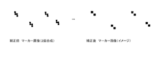
- FIG. 4 illustrates a difference between marker coordinate values obtained from the point cloud data A and the point cloud data B.
- This image is obtained by displaying the point cloud data obtained by the three-dimensional laser light scanning device of the present invention as an image, and displays the point cloud data A and the point cloud data B without stratification.
- the left half of FIG. 4 shows a magnified portion of the measurement of the four checkered markers without applying the mechanical error parameter. It can be seen that the marker coordinates of the point cloud data A and the point cloud data B are displayed two times shifted in the vertical direction.
- the right half of FIG. 4 shows point cloud data corrected by applying an appropriate machine error parameter to the same point cloud data, and the marker coordinate values of point cloud data A and point cloud data B match. Are displayed overlapping. That is, as a result of correcting the point cloud data A and the point cloud data B by the respective mechanical error parameters, the marker coordinate values are matched.
- FIG. 5 shows an example of the aforementioned mechanical error parameter.
- the mechanical error parameters include at least the Z-phase shift of the reflection mirror 2, the angle error, the correction of the tilt angle or the tilt direction, the tilt angle or tilt direction of the laser measurement unit 1, and the tilt of the laser optical axis. Includes angle or tilt direction correction.
- mechanical error parameters correction of the tilt angle or tilt direction of the optical axis of the laser measurement unit 1, phase shift of the mirror encoder 4, correction of the eccentricity or eccentric direction of the disk, phase shift of the spindle encoder 9, correction of the eccentricity or eccentric direction of the disk
- mechanical error parameters such as the position of the reflection point of the reflection mirror 2 (in the X, Y, and Z directions).
- the relationship between the rotational speeds of the mirror drive motor 3 and the spindle drive motor 7 is reversed (mirror drive motor 7). (When the rotation of the motor 3 is slow and the rotation of the spindle drive motor 7 is fast). In this case, the above-mentioned “the lower one of the horizontal rotation speed and the vertical rotation speed in the direction in which the reflection mirror 2 reflects the laser light” is the vertical rotation.
- a plurality of markers are set in the horizontal direction and the vertical direction. Practically, the number of markers is desirably five or more.
- a function capable of calculating a mechanical error parameter can be mounted on the main body of the three-dimensional laser light scanning device, or software having similar functions can be provided to the user. Thereby, the user can easily calibrate the measurement data by using the three-dimensional laser light scanning device and improve the measurement accuracy.
Abstract
The present invention addresses the problem of providing a measurement data correction method for a three-dimensional laser-light-scanning device that makes it possible to enhance measurement accuracy through simple calibration of the three-dimensional laser-light-scanning device by a user. To address this problem, in the present invention: point cloud data, which is obtained in the time it takes for a full rotation at the slower from among the horizontal rotation speed and vertical rotation speed of a reflection mirror (2) of a laser measurement unit (1) in the direction in which laser light is reflected by the reflection mirror, is divided into a pair of layers consisting of point cloud data A and point cloud data B; a prescribed mechanical error parameter is selected; the selected mechanical error parameter is applied to point cloud data A and point cloud data B; marker coordinate values are obtained from point cloud data A and point cloud data B and compared; and a mechanical error parameter correction value resulting in a coordinate value difference less than or equal to a prescribed threshold is calculated.
Description
本開示は、三次元レーザー光走査装置の計測データ較正方法に関するものである。
The present disclosure relates to a measurement data calibration method for a three-dimensional laser light scanning device.
以前より、レーザー光測距を行う装置のレーザー光を三次元空間へ照射し点群データを取得する試みがなされてきた。点群データとは、三次元座標値データ群のことであり、周囲の環境に存在する物体の形状を表現したものなどである。先行技術としては、例えば特開2017-134293号(特許文献1参照)に開示されている技術のような方法が知られている。
Before, attempts have been made to acquire point cloud data by irradiating the laser beam of a device that performs laser beam ranging to a three-dimensional space. The point cloud data is a group of three-dimensional coordinate value data, such as data representing the shape of an object existing in the surrounding environment. As a prior art, for example, a method such as a technique disclosed in Japanese Patent Application Laid-Open No. 2017-134293 (see Patent Document 1) is known.
三次元レーザー光走査装置は、実際には部品の寸法バラツキや光軸調整の誤差などによりレーザー光の発光方向は設計と実際では差があり厳密には一致しない。よって、この差が一定の範囲内に収まるよう三次元レーザー光走査装置の構成部品の機械的な調整を行う必要がある。しかしながら、機械的な調整のみで必要な点群データの精度を得ることは非常に困難でありコストアップの要因となる。
そこで、三次元レーザー光走査装置の構成部品の機械的なずれを測定して実際の測定方向を演算することで点群の精度を向上させる作業が行われている。
これらの作業をキャリブレーションといい、通常は三次元レーザー光走査装置の製造工程において行われる。 In the three-dimensional laser light scanning device, the emission direction of the laser light actually differs from the design due to variations in the dimensions of components and errors in the adjustment of the optical axis, and does not exactly match. Therefore, it is necessary to mechanically adjust the components of the three-dimensional laser light scanning device so that the difference falls within a certain range. However, it is very difficult to obtain the required accuracy of the point cloud data only by mechanical adjustment, which causes a cost increase.
Therefore, an operation of improving the accuracy of the point cloud by measuring the mechanical deviation of the components of the three-dimensional laser light scanning device and calculating the actual measurement direction has been performed.
These operations are called calibration, and are usually performed in the manufacturing process of the three-dimensional laser light scanning device.
しかしながら、キャリブレーションを行うためには、三次元レーザー光走査装置とレーザー光線の幾何学的な位置関係を精密に測定する必要があり、専用の特別な環境が必要となる。このため、製造工程以外でのキャリブレーションの実行は困難である。また、キャリブレーションを行うことができるのは特殊な技能を持った専門家であるため、誰でも行うことができるものではなく、また専門家であっても工数がかかるという問題があった。
However, in order to perform calibration, it is necessary to precisely measure the geometric positional relationship between the three-dimensional laser light scanning device and the laser beam, and a special environment for exclusive use is required. For this reason, it is difficult to execute calibration outside of the manufacturing process. In addition, since calibration can be performed by specialists with special skills, nobody can perform calibration, and there is a problem that even specialists require a lot of man-hours.
本開示はこれらの課題を解決すべくなされたものであり、三次元レーザー光走査装置の計測精度に影響を与える構成部品の機械的なずれを機械誤差パラメーターとして選定し、計測した点群データを補正するキャリブレーション(較正)を行う方法を提案するものである。その目的とするところは、ユーザー自身で三次元レーザー光走査装置の較正を簡易に行って計測精度を高めることができる三次元レーザー光走査装置の計測データ較正方法を提供することにある。
The present disclosure has been made in order to solve these problems, the mechanical deviation of the components that affect the measurement accuracy of the three-dimensional laser light scanning device is selected as a mechanical error parameter, the measured point cloud data. The present invention proposes a method for performing calibration for correction. It is an object of the present invention to provide a method for calibrating measurement data of a three-dimensional laser light scanning device, in which a user himself can easily calibrate the three-dimensional laser light scanning device and improve measurement accuracy.
上記目的を達成するため、以下に述べる実施形態には、次の構成を備える。
レーザー光を投光して被照射体からの反射光を受光することで測距するレーザー光測距装置と、前記レーザー光測距装置から照射されたレーザー光を反射面で反射させて被照射体に向けて照射し、被照射体からの反射光を前記反射面で反射させて受光する反射鏡と、前記反射鏡を水平回転軸を中心に回転駆動させる第一駆動部と、前記レーザー光測距装置と前記第一駆動部を支持固定する回転支持部と、前記回転支持部を鉛直軸を中心に回転駆動させる第二駆動部と、前記レーザー光測距装置、前記第一駆動部及び第二駆動部の動作を制御する制御ユニットと、を備え、前記制御ユニットは、前記第一駆動部と前記第二駆動部を制御して前記回転駆動される反射鏡のレーザー光を反射させる方向を水平方向および垂直方向のそれぞれについて特定の回転速度となるようにしつつ前記レーザー光測距装置を制御してレーザー光測距を行うことにより、前記反射鏡を中心とした任意の半径の仮想的球体の表面である仮想球面の上を一定のパターンで前記レーザー光測距を行うよう制御し、前記反射鏡のレーザー光を反射させる方向の水平回転速度と垂直回転速度のうち遅い方の回転が1周回する間に得られる点群データを点群データAおよび点群データBの2組に層別し、所定の機械誤差パラメーターを選択し、前記点群データAおよび前記点群データBに対して該選択された機械誤差パラメーターを適用してそれぞれの点群データよりマーカーの座標値を得て比較し、該座標値の差が所定閾値以下になるよう前記機械誤差パラメーターの補正値を得ることを特徴とする。 In order to achieve the above object, the embodiments described below have the following configurations.
A laser light measuring device that measures the distance by projecting laser light and receiving reflected light from an object to be illuminated, and irradiating by reflecting laser light emitted from the laser light measuring device on a reflecting surface. A reflecting mirror that irradiates the body with light, reflects reflected light from the irradiated body on the reflecting surface and receives the reflected light, a first driving unit that drives the reflecting mirror to rotate about a horizontal rotation axis, and the laser light. A rotation support unit that supports and fixes the distance measurement device and the first drive unit, a second drive unit that rotationally drives the rotation support unit about a vertical axis, the laser light distance measurement device, the first drive unit, A control unit that controls the operation of a second drive unit, wherein the control unit controls the first drive unit and the second drive unit to reflect the laser light of the rotationally driven reflecting mirror. The horizontal and vertical directions respectively By controlling the laser beam distance measuring device while maintaining a constant rotation speed, the laser beam distance measuring device performs laser beam ranging, so that a virtual spherical surface of an arbitrary radius centered on the reflecting mirror is formed. Is controlled in such a manner that the laser beam ranging is performed in a fixed pattern, and a point cloud obtained during one rotation of the slower rotation of the horizontal rotation speed and the vertical rotation speed in the direction in which the reflecting mirror reflects the laser light. The data is stratified into two sets of point cloud data A and point cloud data B, a predetermined mechanical error parameter is selected, and the selected machine error parameter is determined for the point cloud data A and the point cloud data B. The method is characterized in that the coordinate values of the markers are obtained from the respective point cloud data by applying and compared, and a correction value of the mechanical error parameter is obtained so that the difference between the coordinate values is equal to or less than a predetermined threshold.
より具体的には、レーザー光測距装置の反射鏡のレーザー光を反射させる方向の水平回転速度と垂直回転速度のうち遅い方の回転が1周回する間に得られる点群データを点群データAおよび点群データBの2組に層別し、所定の機械誤差パラメーターを選択し、点群データAおよび点群データBに対して選択された機械誤差パラメーターを適用してそれぞれの点群データよりマーカーの座標値を得て比較し、座標値の差が所定閾値以下になるような機械誤差パラメーターの補正値を算出する。
実際には、点群データAと点群データBのそれぞれで得られるマーカーの座標値の差の二乗平方和が目標値を下回ったところでキャリブレーションは終了とする。これにより、ユーザー自身で三次元レーザー光走査装置を用いて簡易に計測した点群データをしようしてキャリブレーションを行い、計測精度を高めることができる。 More specifically, the point cloud data obtained during one rotation of the slower one of the horizontal rotation speed and the vertical rotation speed in the direction of reflecting the laser light of the reflector of the laser light distance measuring device is referred to as point cloud data. A and a group of point cloud data B are stratified, a predetermined mechanical error parameter is selected, and the selected machine error parameter is applied to the point cloud data A and the point cloud data B to obtain each point cloud data. Further, the coordinate values of the markers are obtained and compared, and a correction value of the mechanical error parameter is calculated so that the difference between the coordinate values is equal to or less than a predetermined threshold.
Actually, the calibration ends when the sum of the squares of the difference between the coordinate values of the markers obtained in the point cloud data A and the point cloud data B falls below the target value. Thereby, calibration can be performed by using the point cloud data easily measured by the user himself using the three-dimensional laser light scanning device, and the measurement accuracy can be improved.
複数の前記機械誤差パラメーターを包含し、初期値として任意の機械誤差パラメーターE=E0、機械誤差パラメーターF=F0を選定して、前記機械誤差パラメーターF=F0の値を固定して前記機械誤差パラメーターEをある範囲内で変化させて最良値E1を求め、次に前記機械誤差パラメーターE=E1を固定して前記機械誤差パラメーターFをある範囲内で変化させて最良値F1を求める計測動作を繰り返すことで、マーカーの座標値の差異が所定閾値以下で最も小さくなるよう収束したときのEn,Fnを補正値として採用することが好ましい。
A plurality of the machine error parameters are included, and arbitrary machine error parameters E = E0 and machine error parameters F = F0 are selected as initial values, and the machine error parameter F = F0 is fixed and the machine error parameter F = F0 is fixed. The best value E1 is obtained by changing E within a certain range, and the measurement operation of obtaining the best value F1 by changing the mechanical error parameter F within a certain range while fixing the mechanical error parameter E = E1 is repeated. Thus, it is preferable to employ En and Fn when the difference between the coordinate values of the markers converges to be the smallest below a predetermined threshold value as the correction value.
これにより、複数の機械誤差パラメーターのうち2つを選択して点群データAと点群データBのそれぞれで得られるマーカーの座標値の差の二乗平方和が閾値より小さくなるよう機械誤差パラメーターの最適値をひとつずつ探索していく。機械誤差パラメーターには相互作用があるため、固定する機械誤差パラメーターを相互に入れ替えて作業を行うことで、較正作業の精度が向上する。そして、点群データAと点群データBのそれぞれで得られるマーカーの座標値の差異が最も小さくなるよう収束したときのEn,Fnを補正値として採用することで、点群データの座標精度を高めることができる。
Thereby, two of the plurality of mechanical error parameters are selected and the sum of the squares of the difference between the coordinate values of the markers obtained in each of the point cloud data A and the point cloud data B becomes smaller than the threshold value. Search for the optimal value one by one. Since the mechanical error parameters have an interaction, the accuracy of the calibration operation is improved by replacing the fixed mechanical error parameters with each other. Then, En and Fn when convergence is performed so as to minimize the difference between the coordinate values of the markers obtained in each of the point cloud data A and the point cloud data B are used as correction values, thereby improving the coordinate accuracy of the point cloud data. Can be enhanced.
前記機械誤差パラメーターは、少なくとも前記反射鏡のZ相ずれ、角度誤差、軸倒れ角度若しくは軸倒れ方向、前記レーザー光測距装置の傾き角度若しくは傾き方向、レーザー光軸の倒れ角度若しくは倒れ方向のいずれかを複数含んでいることが望ましい。
これにより、三次元レーザー光走査装置の寸法精度が十分に出ている場合には、点群データAと点群データBのそれぞれで得られるマーカーの座標値が非常に近い値となるため、三次元レーザー光走査装置を構成する部品の寸法バラツキや光軸調整の誤差、更には測定方向誤差などの機械的な要素に起因する計測精度を機械誤差パラメーターに反映させて点群の座標精度を高めることができる。 The mechanical error parameter is at least any one of a Z-phase shift of the reflecting mirror, an angular error, a tilt angle or a tilt direction, a tilt angle or a tilt direction of the laser beam distance measuring device, and a tilt angle or a tilt direction of the laser optical axis. It is desirable to include a plurality.
Thereby, when the dimensional accuracy of the three-dimensional laser light scanning device is sufficiently high, the coordinate values of the markers obtained by each of the point cloud data A and the point cloud data B are very close values, Improve the coordinate accuracy of point clouds by reflecting the measurement accuracy caused by mechanical factors such as dimensional variations of components constituting the original laser beam scanning device, errors in optical axis adjustment, and measurement direction errors as well as mechanical error parameters. be able to.
ユーザー自身で三次元レーザー光走査装置を用いて簡易に計測した点群データの較正を行って計測精度を高めることができる三次元レーザー光走査装置の計測データ較正方法を提供することができる。
(4) It is possible to provide a measurement data calibration method for a three-dimensional laser light scanning device capable of increasing the measurement accuracy by calibrating point cloud data easily measured by the user himself using the three-dimensional laser light scanning device.
以下、三次元レーザー光走査装置の概略構成について、図1および図2を参照しながら説明する。図1は、三次元レーザー光走査装置の正面図、図2はその斜視図である。
図1及び図2において、レーザー計測ユニット1(レーザー光測距装置)は、レーザー光を発光し、測距対象に照射し、測距対象から反射したレーザー光を受光して、レーザー計測ユニット1と測距対象との直線距離を測定する。 Hereinafter, a schematic configuration of the three-dimensional laser light scanning device will be described with reference to FIGS. 1 and 2. FIG. 1 is a front view of a three-dimensional laser light scanning device, and FIG. 2 is a perspective view thereof.
1 and 2, a laser measuring unit 1 (laser light measuring device) emits a laser beam, irradiates the object to be measured, receives laser light reflected from the object to be measured, and receives the laser beam. The linear distance between the object and the distance measurement object is measured.
具体的には、レーザー計測ユニット1が発光するレーザー光を一旦反射ミラー2(反射鏡)に当てて、ミラー表面における反射を利用して測距対象に向けて照射するようになっている。反射ミラー2としてはロッドミラーが好適に用いられ、円柱状の物質(ガラス等)を斜めに切断しその切断平面に銀などを蒸着したものである。蒸着以外にミラーそのものを切断平面に貼付けても良い。本実施例では、円柱の中心軸と切断平面は45度の傾斜角度を有する。
Specifically, the laser beam emitted by the laser measurement unit 1 is once applied to the reflection mirror 2 (reflection mirror), and is irradiated toward the distance measurement object by utilizing the reflection on the mirror surface. As the reflection mirror 2, a rod mirror is preferably used, which is obtained by diagonally cutting a columnar material (such as glass) and depositing silver or the like on the cut plane. Instead of vapor deposition, the mirror itself may be attached to the cutting plane. In this embodiment, the central axis of the cylinder and the cutting plane have a 45-degree inclination angle.
反射ミラー2は、ミラー駆動モータ3(第一駆動部)により円柱の中心軸(水平回転軸)を中心として回転可能に軸支されている。これにより、レーザー計測ユニット1からのレーザー光は、円柱の中心軸(水平回転軸)から90度の方向へ偏向される。このミラー2の回転により測距のレーザー光は垂直方向のあらゆる角度に向かって照射される。ミラーエンコーダ4は、ミラー駆動モータ3によるミラー2の回転の角度を検出するためのものである。
The reflecting mirror 2 is rotatably supported by a mirror driving motor 3 (first driving unit) so as to be rotatable around a central axis (horizontal rotation axis) of a cylinder. Thereby, the laser beam from the laser measurement unit 1 is deflected in a direction of 90 degrees from the central axis (horizontal rotation axis) of the cylinder. Due to the rotation of the mirror 2, the laser beam for distance measurement is emitted toward all angles in the vertical direction. The mirror encoder 4 is for detecting an angle of rotation of the mirror 2 by the mirror drive motor 3.
レーザー計測ユニット1及びミラー駆動モータ3は回転支持台5(回転支持部)上に支持固定されている。回転支持台5は、設置面に載置固定される支持脚5aと支持脚5aに起立形成された固定軸5bを有する。支持台本体5cは固定軸5bに対して軸受5c1を介して回転可能に支持されている。支持台本体5cの上端部には、上部支持板5dが固定軸5bと直交する方向に支持台本体5cより外側に張り出して設けられている。上部支持板5dには、レーザー計測ユニット1及び制御ユニット6が支持されている。上部支持板5d上には起立板5eが起立形成されており、該起立板5eには、ミラー駆動モータ3が支持固定されている。
(4) The laser measurement unit 1 and the mirror drive motor 3 are supported and fixed on a rotation support 5 (rotation support). The rotary support 5 has a support leg 5a mounted and fixed on the installation surface, and a fixed shaft 5b formed upright on the support leg 5a. The support base body 5c is rotatably supported on the fixed shaft 5b via a bearing 5c1. At the upper end of the support base 5c, an upper support plate 5d is provided so as to protrude outward from the support base 5c in a direction orthogonal to the fixed shaft 5b. The laser measurement unit 1 and the control unit 6 are supported on the upper support plate 5d. An upright plate 5e is formed upright on the upper support plate 5d, and the mirror drive motor 3 is supported and fixed to the upright plate 5e.
支持台本体5cの下端部には、下部支持板5fが固定軸5bと直交する方向に支持台本体5cより外側に張り出して設けられている。下部支持板5f上には、スピンドル駆動モータ7(第二駆動部)がモータ軸7aを下向きに支持固定されている。モータ軸7aにはモータ歯車8aが一体に設けられている。またモータ歯車8aは固定軸5bに一体に組み付けられた固定歯車8bと噛み合っている。固定軸5bにはスピンドルエンコーダ9が設けられている。スピンドルエンコーダ9は、スピンドル駆動モータ7による支持台本体5cの回転の角度を検出するためのものである。
下部 At the lower end of the support base 5c, a lower support plate 5f is provided so as to protrude outward from the support base 5c in a direction orthogonal to the fixed shaft 5b. On the lower support plate 5f, a spindle drive motor 7 (second drive unit) is supported and fixed with the motor shaft 7a facing downward. A motor gear 8a is provided integrally with the motor shaft 7a. The motor gear 8a meshes with a fixed gear 8b integrated with the fixed shaft 5b. A spindle encoder 9 is provided on the fixed shaft 5b. The spindle encoder 9 is for detecting an angle of rotation of the support base body 5c by the spindle drive motor 7.
制御ユニット6(制御部)は、レーザー計測ユニット1、ミラー駆動モータ3及びスピンドル駆動モータ7の動作を統括的に制御する。制御ユニット6にはミラーエンコーダ4からミラー駆動モータ3の回転情報、スピンドルエンコーダ9からスピンドル駆動モータ7の回転情報を取得してこれらの回転駆動を制御する。具体的には、制御ユニット6は、ミラー駆動モータ3とスピンドル駆動モータ7を制御して反射ミラー2のレーザー光を反射させる方向を変化させつつレーザー計測ユニット1を制御してレーザー光測距を行う。
The control unit 6 (control unit) controls the operations of the laser measurement unit 1, the mirror drive motor 3 and the spindle drive motor 7 as a whole. The control unit 6 obtains rotation information of the mirror drive motor 3 from the mirror encoder 4 and rotation information of the spindle drive motor 7 from the spindle encoder 9 and controls these rotation drives. Specifically, the control unit 6 controls the laser drive unit 3 while controlling the mirror drive motor 3 and the spindle drive motor 7 to change the direction in which the reflection mirror 2 reflects the laser light, thereby performing laser light ranging. Do.
スピンドル駆動モータ7を回転駆動すると、モータ軸7aに設けられたモータ歯車8aが回転する。モータ歯車8aは固定軸5bに設けられた固定歯車8bに噛み合いながら公転する。これにより、支持台本体5cが軸受5c1を介して固定軸5bを中心として回転させる。よって、回転支持台5が回転するので、回転支持台5に組み付けられたレーザー計測ユニット1及び反射ミラー2も固定軸5bを中心として自転することとなる。
(4) When the spindle drive motor 7 is driven to rotate, the motor gear 8a provided on the motor shaft 7a rotates. The motor gear 8a revolves while engaging with the fixed gear 8b provided on the fixed shaft 5b. Thus, the support base body 5c rotates about the fixed shaft 5b via the bearing 5c1. Therefore, since the rotation support 5 rotates, the laser measurement unit 1 and the reflection mirror 2 assembled on the rotation support 5 also rotate about the fixed shaft 5b.
このように、レーザー計測ユニット1が発光するレーザー光を反射ミラー2にてレーザー光照射方向を90°偏向させて水平回転軸を中心として回転させることで垂直方向の全周へ照射し、かつレーザー計測ユニット1及び反射ミラー2は回転支持台5と共に固定軸5bを中心に自転を行うことで、周囲に対する全球的な三次元レーザー光走査を実現している。結果として、反射ミラー2を中心とした任意の半径の仮想的球体の表面である仮想球面10の上を一定のパターンでレーザー光測距を行うことになる。
尚、回転支持台5に対するレーザー計測ユニット1、ミラー駆動モータ3、制御ユニット6及びスピンドル駆動モータ7の組み付けは、固定軸5bを中心とする回転支持台5の回転バランスを考慮して組み付けられるのが好ましい。本実施例では、レーザー計測ユニット1及び制御ユニット6とミラー駆動モータ3及びスピンドル駆動モータ7とで重量バランスの調整がされている。 In this way, the laser beam emitted by thelaser measuring unit 1 is irradiated on the entire circumference in the vertical direction by rotating the laser beam irradiation direction by 90 ° by the reflection mirror 2 and rotating about the horizontal rotation axis, and The measurement unit 1 and the reflection mirror 2 rotate around the fixed shaft 5b together with the rotation support 5 to realize a global three-dimensional laser beam scanning with respect to the surroundings. As a result, laser light ranging is performed in a fixed pattern on the virtual spherical surface 10 which is the surface of a virtual sphere having an arbitrary radius centered on the reflection mirror 2.
The assembly of thelaser measuring unit 1, the mirror drive motor 3, the control unit 6, and the spindle drive motor 7 to the rotary support 5 is performed in consideration of the rotational balance of the rotary support 5 about the fixed shaft 5b. Is preferred. In this embodiment, the weight balance is adjusted by the laser measurement unit 1 and the control unit 6, the mirror drive motor 3 and the spindle drive motor 7.
尚、回転支持台5に対するレーザー計測ユニット1、ミラー駆動モータ3、制御ユニット6及びスピンドル駆動モータ7の組み付けは、固定軸5bを中心とする回転支持台5の回転バランスを考慮して組み付けられるのが好ましい。本実施例では、レーザー計測ユニット1及び制御ユニット6とミラー駆動モータ3及びスピンドル駆動モータ7とで重量バランスの調整がされている。 In this way, the laser beam emitted by the
The assembly of the
図3は、仮に三次元レーザー光走査装置の周囲に任意の半径の透明な球体が仮想的に存在するとした場合、この球体の表面(以下「仮想球面10」という)上に測距用レーザー光がどのように照射されるかを概念的に例示するものである。即ち、反射ミラー2がミラー駆動モータ3とスピンドル駆動モータ7の回転の合成によって一定のパターンを以って運動し反射面の方向がどの様に変化するか、加えてレーザー計測ユニット1が発光するレーザー光が反射ミラー2で反射された結果として仮想球面10上に測距用レーザー光の軌跡(走査線)がどのようなパターンを描くか(走査パターン)を示したイメージ図である。
本実施例においては、反射ミラー2の質量に比べて回転支持台5の質量の方が大きいため、ミラー駆動モータ3の回転速度はスピンドル駆動モータ7の回転速度に比べて大幅に高くなるように設定している。図示の条件では、仮想球面10上に照射されるレーザー光は緯度(上下)方向に密となり、経度(水平)方向に粗となっている。緯度方向、経度方向にどのような密度で計測するかは各スピンドルの回転速度と測定レートによって調整が可能である。等速回転、一定レートの測距をする場合には仮想球面10の北極点付近においてレーザー光の照射される点の密度が高くなる。 FIG. 3 shows a case where a transparent sphere having an arbitrary radius virtually exists around the three-dimensional laser light scanning device, and a laser beam for distance measurement is placed on the surface of the sphere (hereinafter referred to as “virtualspherical surface 10”). Are conceptually illustrated as examples of how is irradiated. That is, the reflection mirror 2 moves in a fixed pattern by the combination of the rotations of the mirror drive motor 3 and the spindle drive motor 7 to change the direction of the reflection surface, and additionally, the laser measurement unit 1 emits light. FIG. 4 is an image diagram showing what pattern (scanning pattern) a locus (scanning line) of the laser beam for distance measurement draws on a virtual spherical surface 10 as a result of the laser light being reflected by a reflection mirror 2.
In this embodiment, since the mass of therotary support 5 is larger than the mass of the reflection mirror 2, the rotation speed of the mirror drive motor 3 is set to be much higher than the rotation speed of the spindle drive motor 7. You have set. Under the conditions shown in the figure, the laser light irradiated onto the virtual spherical surface 10 is dense in the latitude (vertical) direction and coarse in the longitude (horizontal) direction. The density at which the measurement is performed in the latitude and longitude directions can be adjusted by the rotational speed of each spindle and the measurement rate. When measuring at a constant speed and at a constant rate, the density of points irradiated with laser light near the north pole of the virtual spherical surface 10 increases.
本実施例においては、反射ミラー2の質量に比べて回転支持台5の質量の方が大きいため、ミラー駆動モータ3の回転速度はスピンドル駆動モータ7の回転速度に比べて大幅に高くなるように設定している。図示の条件では、仮想球面10上に照射されるレーザー光は緯度(上下)方向に密となり、経度(水平)方向に粗となっている。緯度方向、経度方向にどのような密度で計測するかは各スピンドルの回転速度と測定レートによって調整が可能である。等速回転、一定レートの測距をする場合には仮想球面10の北極点付近においてレーザー光の照射される点の密度が高くなる。 FIG. 3 shows a case where a transparent sphere having an arbitrary radius virtually exists around the three-dimensional laser light scanning device, and a laser beam for distance measurement is placed on the surface of the sphere (hereinafter referred to as “virtual
In this embodiment, since the mass of the
本実施例では、前記の通り、ミラー駆動モータ3の回転速度はスピンドル駆動モータ7の回転速度と比較して大幅に高い。
反射ミラー2は、スピンドル駆動モータ7の回転駆動力とミラー駆動モータ3の回転駆動力とが合成された結果、図3に例示したように、レーザー計測ユニット1が発光するレーザー光を仮想球面10上に、南北方向に密で東西方向に疎となる一定の走査パターンを描くように照射されるが、これは走査パターンを説明するためにパターン全体を描いたものである。
より短い時間においては、ミラー駆動モータ3の回転駆動力によってレーザー光が反射される方向が南北に1周する間にスピンドル駆動モータ7の回転駆動力によってレーザー光が反射される方向が東西にわずかに回転することになる。
この際にレーザー光が仮想球面10上に描く走査線は、厳密には円弧では無いが、仮想球面10上で経線が東西方向へ螺旋状に僅かに歪んだ円弧に近い形状となる。
このレーザー光が反射される方向が南北に1周することで、仮想球面10上のある経度の経線上を走査線が1周することになる(走査線は厳密には経線に合致しない)。 In this embodiment, as described above, the rotation speed of themirror drive motor 3 is significantly higher than the rotation speed of the spindle drive motor 7.
As a result of the combination of the rotational driving force of thespindle driving motor 7 and the rotational driving force of the mirror driving motor 3, the reflecting mirror 2 converts the laser light emitted by the laser measurement unit 1 into a virtual spherical surface 10 as illustrated in FIG. Above, irradiation is performed so as to draw a fixed scanning pattern that is dense in the north-south direction and sparse in the east-west direction. This is an entire pattern drawn to explain the scanning pattern.
In a shorter time, while the direction in which the laser light is reflected by the rotational driving force of themirror driving motor 3 makes one round from north to south, the direction in which the laser light is reflected by the rotational driving force of the spindle driving motor 7 is slightly east-west. Will rotate.
At this time, the scanning line drawn by the laser beam on the virtualspherical surface 10 is not strictly an arc, but has a shape close to an arc in which the meridian is slightly distorted spirally in the east-west direction on the virtual spherical surface 10.
When the direction in which the laser light is reflected makes one round from north to south, the scanning line makes one round on a meridian at a certain longitude on the virtual spherical surface 10 (the scanning line does not exactly match the meridian).
反射ミラー2は、スピンドル駆動モータ7の回転駆動力とミラー駆動モータ3の回転駆動力とが合成された結果、図3に例示したように、レーザー計測ユニット1が発光するレーザー光を仮想球面10上に、南北方向に密で東西方向に疎となる一定の走査パターンを描くように照射されるが、これは走査パターンを説明するためにパターン全体を描いたものである。
より短い時間においては、ミラー駆動モータ3の回転駆動力によってレーザー光が反射される方向が南北に1周する間にスピンドル駆動モータ7の回転駆動力によってレーザー光が反射される方向が東西にわずかに回転することになる。
この際にレーザー光が仮想球面10上に描く走査線は、厳密には円弧では無いが、仮想球面10上で経線が東西方向へ螺旋状に僅かに歪んだ円弧に近い形状となる。
このレーザー光が反射される方向が南北に1周することで、仮想球面10上のある経度の経線上を走査線が1周することになる(走査線は厳密には経線に合致しない)。 In this embodiment, as described above, the rotation speed of the
As a result of the combination of the rotational driving force of the
In a shorter time, while the direction in which the laser light is reflected by the rotational driving force of the
At this time, the scanning line drawn by the laser beam on the virtual
When the direction in which the laser light is reflected makes one round from north to south, the scanning line makes one round on a meridian at a certain longitude on the virtual spherical surface 10 (the scanning line does not exactly match the meridian).
このように、走査線が仮想球面10上の経線をなぞるように周回することを継続した状態で、スピンドル駆動モータ7が回転駆動し反射ミラー2が水平方向に半周(180度)回転する間に、反射ミラー2を中心とした全球の点群データを得ることができる。
引き続いて、もう半周(180度)回転する間に、反射ミラー2を中心とした全球のもう1つの点群データを同様に得ることができる。
このようにして、反射ミラー2のレーザー光を反射させる方向の水平回転速度と垂直回転速度のうち遅い方の回転である水平回転が1周回する間に得られる点群データを2組の点群データに層別する。
これら2組の点群データをそれぞれ点群データAおよび点群データBとする。
なお、前述では、水平回転角度の0~180度と180~360度とでそれぞれ得られる点群データを点群データAと点群データBとしたが、異なる考え方として、反射ミラー2のレーザー光を反射させる方向の水平回転角度の1周回の0~360度において、垂直回転角度(真上を0度)について0~180度側で得られる点群データと180~360度側で得られる点群データを、それぞれ点群データAと点群データBとしても良い。また、より精度を高めるために、複数周回してより多くの点群データを用いて処理してもよい。 In this manner, while the scanning line continues to circulate along the meridian on the phantomspherical surface 10, while the spindle drive motor 7 is driven to rotate and the reflection mirror 2 rotates half a circle (180 degrees) in the horizontal direction. , It is possible to obtain global point cloud data centering on the reflection mirror 2.
Subsequently, another point group data of the whole sphere centering on thereflection mirror 2 can be obtained in the same manner during another half rotation (180 degrees).
In this manner, the point cloud data obtained during one rotation of the horizontal rotation, which is the slower of the horizontal rotation speed and the vertical rotation speed in the direction in which the reflectingmirror 2 reflects the laser light, is converted into two sets of point clouds. Stratify by data.
These two sets of point cloud data are referred to as point cloud data A and point cloud data B, respectively.
In the above description, the point cloud data obtained at the horizontal rotation angles of 0 to 180 degrees and 180 to 360 degrees are the point cloud data A and the point cloud data B, respectively. At 0 to 360 degrees of one rotation of the horizontal rotation angle in the direction in which light is reflected, the point group data obtained at 0 to 180 degrees and the points obtained at 180 to 360 degrees for the vertical rotation angle (0 degree directly above) The group data may be point cloud data A and point cloud data B, respectively. Further, in order to further increase the accuracy, the processing may be performed using a larger number of point group data by making multiple rounds.
引き続いて、もう半周(180度)回転する間に、反射ミラー2を中心とした全球のもう1つの点群データを同様に得ることができる。
このようにして、反射ミラー2のレーザー光を反射させる方向の水平回転速度と垂直回転速度のうち遅い方の回転である水平回転が1周回する間に得られる点群データを2組の点群データに層別する。
これら2組の点群データをそれぞれ点群データAおよび点群データBとする。
なお、前述では、水平回転角度の0~180度と180~360度とでそれぞれ得られる点群データを点群データAと点群データBとしたが、異なる考え方として、反射ミラー2のレーザー光を反射させる方向の水平回転角度の1周回の0~360度において、垂直回転角度(真上を0度)について0~180度側で得られる点群データと180~360度側で得られる点群データを、それぞれ点群データAと点群データBとしても良い。また、より精度を高めるために、複数周回してより多くの点群データを用いて処理してもよい。 In this manner, while the scanning line continues to circulate along the meridian on the phantom
Subsequently, another point group data of the whole sphere centering on the
In this manner, the point cloud data obtained during one rotation of the horizontal rotation, which is the slower of the horizontal rotation speed and the vertical rotation speed in the direction in which the reflecting
These two sets of point cloud data are referred to as point cloud data A and point cloud data B, respectively.
In the above description, the point cloud data obtained at the horizontal rotation angles of 0 to 180 degrees and 180 to 360 degrees are the point cloud data A and the point cloud data B, respectively. At 0 to 360 degrees of one rotation of the horizontal rotation angle in the direction in which light is reflected, the point group data obtained at 0 to 180 degrees and the points obtained at 180 to 360 degrees for the vertical rotation angle (0 degree directly above) The group data may be point cloud data A and point cloud data B, respectively. Further, in order to further increase the accuracy, the processing may be performed using a larger number of point group data by making multiple rounds.
三次元レーザー光走査装置の計測精度に影響を与える構成部品の機械的なずれが無い理想的な状況である場合、点群データAと点群データBは周囲の形状データとしては合同であり、較正の目的で周囲に配置しているマーカー(市松模様が描かれた板状物や球などの特徴物)の座標値は同一値を示す筈である。
しかしながら、前述の通り、実際には三次元レーザー光走査装置には構成部品の機械的なずれが存在するため、点群データAから得られるマーカー座標値と点群データBから得られるマーカー座標値を比較すると異なる値を示すことになる。
このような点群データに影響を及ぼす構成部品の機械的なずれのことを本発明では機械誤差パラメーターと定義している。機械誤差パラメーターは複数存在し、それぞれを数値として取り扱う。
取得した点群データは適切な機械誤差パラメーターを適用して補正することで精度の高いものとなり、前述の「マーカー座標値の差異」も極めて小さくなる。 In an ideal situation where there is no mechanical displacement of the components that affect the measurement accuracy of the three-dimensional laser light scanning device, the point cloud data A and the point cloud data B are congruent as the surrounding shape data, Coordinate values of markers (characteristics such as a checkerboard-shaped plate or a sphere) placed around for the purpose of calibration should show the same value.
However, as described above, in actuality, there is mechanical displacement of the components in the three-dimensional laser light scanning device, and therefore, the marker coordinate values obtained from the point cloud data A and the marker coordinate values obtained from the point cloud data B Will show different values.
In the present invention, such a mechanical displacement of a component that affects the point cloud data is defined as a mechanical error parameter. There are a plurality of mechanical error parameters, each of which is treated as a numerical value.
The acquired point cloud data is highly accurate when corrected by applying an appropriate machine error parameter, and the "difference in marker coordinate values" is extremely small.
しかしながら先述の従来方法では、三次元レーザー光走査装置とレーザー光線の幾何学的な位置関係を精密に測定して機械誤差パラメーターの値を得るためには、専用の特別な環境下で特殊な技能を持った専門家が工数をかけて行う必要があった。このため、装置の出荷後においてユーザー自身がこの作業を行うのは困難であった。
However, in the above-mentioned conventional method, in order to accurately measure the geometric positional relationship between the three-dimensional laser light scanning device and the laser beam and obtain the value of the mechanical error parameter, special skills are required in a special special environment. It was necessary for the expert to take the time and effort. For this reason, it has been difficult for the user himself to perform this operation after shipping the device.
本発明の主旨は、点群データAと点群データBに対して所定の機械誤差パラメーターを適用して補正を行った上でそれぞれの点群データからマーカー座標値を得て2つの座標値を比較して差異を求め、この差異が機械誤差パラメーターを変動させた際にどのように変化するかを確認し、差異が小さくなるときの機械誤差パラメーターを適切なものとして採用することで、較正を行おうとするものである。
すなわち、合同性のある2組の点群データAと点群データBを用いて、それぞれの点群データより得られるマーカー座標値は本来同一であることに基づき、機械誤差パラメーターを演算によって求める、ということである。 The gist of the present invention is to perform correction by applying a predetermined mechanical error parameter to the point cloud data A and the point cloud data B, obtain marker coordinate values from each point cloud data, and calculate two coordinate values. Comparing for differences, checking how these differences change when the machine error parameters are varied, and using the machine error parameters when the differences are small as appropriate, It is what we are going to do.
That is, using two sets of congruent point cloud data A and point cloud data B, based on the fact that the marker coordinate values obtained from the respective point cloud data are originally the same, a machine error parameter is obtained by calculation. That's what it means.
較正作業を行う場合には、前述の通り2組の合同性のある点群データが必要である。本実施例の場合、反射ミラー2のレーザー光を反射させる方向の水平回転速度と垂直回転速度のうち遅い方の回転である水平回転が1周回し、この間に計測された点群データを2組の点群データに層別する。
When performing calibration work, two sets of congruent point cloud data are required as described above. In the case of the present embodiment, the horizontal rotation, which is the slower of the horizontal rotation speed and the vertical rotation speed in the direction in which the laser light is reflected by the reflection mirror 2, makes one revolution, and two sets of point group data measured during this period. Stratified into point cloud data.
例えば図3において、反射ミラー2のレーザー光を反射させる方向が水平方向に1周回している間、垂直方向においてP側(反射ミラー2の0→180°)で得られた点群データを点群データA、Q側(反射ミラー2の180→360°=0°)で得られた点群データを点群データBに層別する。あるいは、スピンドル駆動モータ7が水平方向にX(仮想球面10の手前側の赤道上)からY(0→180°)にかけて回転した際に得られる点群データを点群データA、同様に同じ回転方向でYからX(180→360°=0°)にかけて回転した際に得られる点群データを点群データBとしても良い。
すなわち、合同性のある2組の点群データが得られればどちらでも良い。 For example, in FIG. 3, the point group data obtained on the P side (0 → 180 ° of the reflection mirror 2) in the vertical direction while the laser beam reflecting direction of thereflection mirror 2 makes one round in the horizontal direction is represented by a point. The point group data obtained on the group data A, Q side (180 → 360 ° = 0 ° of the reflection mirror 2) is stratified into point group data B. Alternatively, the point cloud data obtained when the spindle drive motor 7 rotates from X (on the equator on the near side of the virtual spherical surface 10) to Y (0 → 180 °) in the horizontal direction is referred to as the point cloud data A, and similarly the same rotation. The point group data obtained when rotating in the direction from Y to X (180 → 360 ° = 0 °) may be used as the point group data B.
That is, any two sets of point group data having congruency can be obtained.
すなわち、合同性のある2組の点群データが得られればどちらでも良い。 For example, in FIG. 3, the point group data obtained on the P side (0 → 180 ° of the reflection mirror 2) in the vertical direction while the laser beam reflecting direction of the
That is, any two sets of point group data having congruency can be obtained.
このようにして得られた2組の点群データに対して、複数ある機械誤差パラメーターのうち1つを選択し、この機械誤差パラメーターの数値を一定の範囲内で一定の変化量を以って複数回変動させ、変動の度ごとに点群データAおよび点群データBに対して適用してマーカー座標を得て比較し差異を求める。この差異が所定の閾値以下となる機械誤差パラメーターの数値が適切なものとして採用される。
With respect to the two sets of point cloud data obtained in this way, one of a plurality of mechanical error parameters is selected, and the numerical value of the mechanical error parameter is changed within a certain range with a certain amount of change. It is changed a plurality of times and applied to the point cloud data A and the point cloud data B for each change to obtain and compare the marker coordinates to obtain the difference. A numerical value of a mechanical error parameter in which this difference is equal to or smaller than a predetermined threshold value is adopted as an appropriate value.
さらには、複数の機械誤差パラメーターのうち任意の2つの機械誤差パラメーターを選択して、初期値として任意の機械誤差パラメーターE=E0、機械誤差パラメーターF=F0を選定して、前記機械誤差パラメーターF=F0の値を固定して前記機械誤差パラメーターEをある範囲内で順次値を変化させて最良値E1を求め、次に前記機械誤差パラメーターE=E1を固定して前記機械誤差パラメーターFをある範囲内で順次値を変化させて最良値F1を求める計測動作を繰り返す。そして、点群データAと点群データBのそれぞれのマーカーの座標値の差の二乗平方和が閾値以下で最も小さくなるよう収束したときに較正作業を終了し、その際のEnとFnをそれぞれ機械誤差パラメーターEおよびFの値として採用する。
Further, any two mechanical error parameters are selected from a plurality of mechanical error parameters, and arbitrary mechanical error parameters E = E0 and mechanical error parameters F = F0 are selected as initial values. = F0 is fixed, and the mechanical error parameter E is sequentially changed within a certain range to obtain the best value E1, and then the mechanical error parameter E is fixed by fixing the mechanical error parameter E = E1. The measurement operation of obtaining the best value F1 by sequentially changing the value within the range is repeated. Then, when the sum of the squares of the difference between the coordinate values of the markers of the point cloud data A and the point cloud data B converges to be the threshold value or less and becomes the smallest, the calibration work is ended, and En and Fn at that time are respectively set. It is adopted as the values of the mechanical error parameters E and F.
図4は、点群データAと点群データBから得られるマーカー座標値の差異について説明するものである。この画像は、本発明の三次元レーザー光走査装置で得られた点群データを画像として表示したもので点群データAと点群データBを層別せず表示している。図4の左半図は、4つの市松模様のマーカーを測定した部分を拡大したものについて、機械誤差パラメーターを適用せずに表示している。点群データAと点群データBのマーカー座標が上下方向にずれて2重に表示されていることがわかる。
図4の右半図は、おなじ点群データに、適切な機械誤差パラメーターを適用して補正された点群データを示しており、点群データAと点群データBのマーカー座標値が一致しているため重なって表示されている。すなわち、点群データAと点群データBをそれぞれ機械誤差パラメーターによって補正した結果、マーカー座標値が一致するようになったことを示している。 FIG. 4 illustrates a difference between marker coordinate values obtained from the point cloud data A and the point cloud data B. This image is obtained by displaying the point cloud data obtained by the three-dimensional laser light scanning device of the present invention as an image, and displays the point cloud data A and the point cloud data B without stratification. The left half of FIG. 4 shows a magnified portion of the measurement of the four checkered markers without applying the mechanical error parameter. It can be seen that the marker coordinates of the point cloud data A and the point cloud data B are displayed two times shifted in the vertical direction.
The right half of FIG. 4 shows point cloud data corrected by applying an appropriate machine error parameter to the same point cloud data, and the marker coordinate values of point cloud data A and point cloud data B match. Are displayed overlapping. That is, as a result of correcting the point cloud data A and the point cloud data B by the respective mechanical error parameters, the marker coordinate values are matched.
前述の機械誤差パラメーターの一例を図5に示す。図5に示すように、機械誤差パラメーターは、少なくとも反射ミラー2のZ相ずれ、角度誤差、軸倒れ角度若しくは軸倒れ方向の補正、レーザー計測ユニット1の傾き角度若しくは傾き方向、レーザー光軸の倒れ角度若しくは倒れ方向の補正を含んでいる。
これにより、三次元レーザー光走査装置における構成部品の機械的なずれをある程度許容した場合であっても、前述の方法で算出した機械誤差パラメーターを加味することで点群データに基づいた座標精度を高めることができる。 FIG. 5 shows an example of the aforementioned mechanical error parameter. As shown in FIG. 5, the mechanical error parameters include at least the Z-phase shift of thereflection mirror 2, the angle error, the correction of the tilt angle or the tilt direction, the tilt angle or tilt direction of the laser measurement unit 1, and the tilt of the laser optical axis. Includes angle or tilt direction correction.
Thereby, even when mechanical deviation of the components in the three-dimensional laser light scanning device is allowed to some extent, the coordinate accuracy based on the point cloud data can be improved by taking into account the mechanical error parameter calculated by the above-described method. Can be enhanced.
これにより、三次元レーザー光走査装置における構成部品の機械的なずれをある程度許容した場合であっても、前述の方法で算出した機械誤差パラメーターを加味することで点群データに基づいた座標精度を高めることができる。 FIG. 5 shows an example of the aforementioned mechanical error parameter. As shown in FIG. 5, the mechanical error parameters include at least the Z-phase shift of the
Thereby, even when mechanical deviation of the components in the three-dimensional laser light scanning device is allowed to some extent, the coordinate accuracy based on the point cloud data can be improved by taking into account the mechanical error parameter calculated by the above-described method. Can be enhanced.
尚、上記機械誤差パラメーターの他にも、更に多くの他の機械誤差パラメーターを含んでいてもよい。例えば、レーザー計測ユニット1の光軸倒れ角度若しくは光軸倒れ方向の補正、ミラーエンコーダ4の位相ずれ、ディスクの偏心若しくは偏心方向の補正、スピンドルエンコーダ9の位相ずれ、ディスクの偏心若しくは偏心方向の補正、反射ミラー2の反射点位置(X,Y,Z方向)など他の機械誤差パラメーターを含んでいてもよい。
Note that, in addition to the above-described mechanical error parameters, more other mechanical error parameters may be included. For example, correction of the tilt angle or tilt direction of the optical axis of the laser measurement unit 1, phase shift of the mirror encoder 4, correction of the eccentricity or eccentric direction of the disk, phase shift of the spindle encoder 9, correction of the eccentricity or eccentric direction of the disk And other mechanical error parameters such as the position of the reflection point of the reflection mirror 2 (in the X, Y, and Z directions).
以上は、ミラー駆動モータ3の回転が速くスピンドル駆動モータ7の回転が遅い三次元レーザー光走査装置について説明してきたが、ミラー駆動モータ3とスピンドル駆動モータ7の回転速度の関係が逆(ミラー駆動モータ3の回転が遅くスピンドル駆動モータ7の回転が速い場合)であっても良い。
この場合、前述の「反射ミラー2のレーザー光を反射させる方向の水平回転速度と垂直回転速度のうち遅い方」は垂直回転となる。 Although the three-dimensional laser light scanning device in which themirror drive motor 3 rotates fast and the spindle drive motor 7 rotates slowly has been described above, the relationship between the rotational speeds of the mirror drive motor 3 and the spindle drive motor 7 is reversed (mirror drive motor 7). (When the rotation of the motor 3 is slow and the rotation of the spindle drive motor 7 is fast).
In this case, the above-mentioned “the lower one of the horizontal rotation speed and the vertical rotation speed in the direction in which thereflection mirror 2 reflects the laser light” is the vertical rotation.
この場合、前述の「反射ミラー2のレーザー光を反射させる方向の水平回転速度と垂直回転速度のうち遅い方」は垂直回転となる。 Although the three-dimensional laser light scanning device in which the
In this case, the above-mentioned “the lower one of the horizontal rotation speed and the vertical rotation speed in the direction in which the
また、マーカーについては、マーカーの配置は水平方向および垂直方向に複数設定することが好適である。実用的にはマーカーの数は5つ以上が望ましい。
マ ー カ ー Further, it is preferable that a plurality of markers are set in the horizontal direction and the vertical direction. Practically, the number of markers is desirably five or more.
上述した三次元レーザー光走査装置の計測データ較正方法を用いれば、機械誤差パラメーターの算出できる機能を三次元レーザー光走査装置本体に搭載したり、同様の機能を持つソフトウェアをユーザーに提供したりすることによって、ユーザー自身で三次元レーザー光走査装置を用いて簡易に計測データの較正を行って計測精度を高めることができる。
By using the above-described measurement data calibration method of the three-dimensional laser light scanning device, a function capable of calculating a mechanical error parameter can be mounted on the main body of the three-dimensional laser light scanning device, or software having similar functions can be provided to the user. Thereby, the user can easily calibrate the measurement data by using the three-dimensional laser light scanning device and improve the measurement accuracy.
By using the above-described measurement data calibration method of the three-dimensional laser light scanning device, a function capable of calculating a mechanical error parameter can be mounted on the main body of the three-dimensional laser light scanning device, or software having similar functions can be provided to the user. Thereby, the user can easily calibrate the measurement data by using the three-dimensional laser light scanning device and improve the measurement accuracy.
Claims (3)
- レーザー光を投光して被照射体からの反射光を受光することで測距するレーザー光測距装置と、
前記レーザー光測距装置から照射されたレーザー光を反射面で反射させて被照射体に向けて照射し、被照射体からの反射光を前記反射面で反射させて受光する反射鏡と、
前記反射鏡を水平回転軸を中心に回転駆動させる第一駆動部と、
前記レーザー光測距装置と前記第一駆動部を支持固定する回転支持部と、
前記回転支持部を鉛直軸を中心に回転駆動させる第二駆動部と、
前記レーザー光測距装置、前記第一駆動部及び第二駆動部の動作を制御する制御ユニットと、を備え、
前記制御ユニットは、前記第一駆動部と前記第二駆動部を制御して前記回転駆動される反射鏡のレーザー光を反射させる方向を水平方向および垂直方向のそれぞれについて特定の回転速度となるようにしつつ前記レーザー光測距装置を制御してレーザー光測距を行うことにより、前記反射鏡を中心とした任意の半径の仮想的球体の表面である仮想球面の上を一定のパターンで前記レーザー光測距を行うよう制御し、
前記反射鏡のレーザー光を反射させる方向の水平回転速度と垂直回転速度のうち遅い方の回転が1周回する間に得られる点群データを点群データAおよび点群データBの2組に層別し、所定の機械誤差パラメーターを選択し、前記点群データAおよび前記点群データBに対して該選択された機械誤差パラメーターを適用してそれぞれの点群データよりマーカーの座標値を得て比較し、該座標値の差が所定閾値以下になるような前記機械誤差パラメーターの補正値を算出し使用することを特徴とする三次元レーザー光走査装置の計測データ較正方法。 A laser light distance measuring device that measures a distance by projecting a laser beam and receiving reflected light from an object to be irradiated,
A reflecting mirror that reflects the laser light emitted from the laser light distance measuring device on a reflecting surface and irradiates the object to be irradiated, and reflects the reflected light from the irradiated object on the reflecting surface to receive light.
A first driving unit that drives the reflecting mirror to rotate about a horizontal rotation axis,
A rotation support unit that supports and fixes the laser light ranging device and the first drive unit,
A second drive unit that drives the rotation support unit to rotate about a vertical axis,
The laser light ranging device, comprising a control unit that controls the operation of the first drive unit and the second drive unit,
The control unit controls the first drive unit and the second drive unit so that the direction in which the rotationally driven reflecting mirror reflects the laser light has a specific rotation speed in each of the horizontal direction and the vertical direction. By controlling the laser beam distance measuring device while performing laser beam ranging, the laser beam is measured in a fixed pattern on a virtual spherical surface which is a surface of a virtual sphere having an arbitrary radius centered on the reflecting mirror. Control to perform optical ranging,
The point cloud data obtained during one rotation of the slower of the horizontal rotation speed and the vertical rotation speed in the direction in which the reflecting mirror reflects the laser light is layered into two sets of point cloud data A and point cloud data B. Separately, a predetermined mechanical error parameter is selected, and the coordinate value of a marker is obtained from each point cloud data by applying the selected mechanical error parameter to the point cloud data A and the point cloud data B. A method for calibrating measurement data of a three-dimensional laser light scanning device, comprising: comparing and calculating and using a correction value of the mechanical error parameter such that the difference between the coordinate values is equal to or less than a predetermined threshold value. - 複数の前記機械誤差パラメーターを包含し、初期値として任意の機械誤差パラメーターE=E0、機械誤差パラメーターF=F0を選定して、前記機械誤差パラメーターF=F0の値を固定して前記機械誤差パラメーターEをある範囲内で変化させて最良値E1を求め、次に前記機械誤差パラメーターE=E1を固定して前記機械誤差パラメーターFをある範囲内で変化させて最良値F1を求める計測動作を繰り返すことで、マーカーの座標値の差異が所定閾値以下で最も小さくなるよう収束したときのEn,Fnを補正値として採用する請求項1記載の三次元レーザー光走査装置の計測データ較正方法。 A plurality of the machine error parameters are included, and arbitrary machine error parameters E = E0 and machine error parameters F = F0 are selected as initial values, and the machine error parameter F = F0 is fixed and the machine error parameter F = F0 is fixed. The best value E1 is obtained by changing E within a certain range, and then the measurement operation of obtaining the best value F1 by changing the mechanical error parameter F within a certain range while fixing the mechanical error parameter E = E1 is repeated. 2. The method for calibrating measurement data of a three-dimensional laser light scanning device according to claim 1, wherein En and Fn when the difference between the coordinate values of the markers converges to a minimum below a predetermined threshold value are adopted.
- 前記機械誤差パラメーターは、少なくとも前記反射鏡のZ相ずれ、角度誤差、軸倒れ角度若しくは軸倒れ方向の補正、前記レーザー光測距装置の傾き角度若しくは傾き方向、レーザー光軸の倒れ角度若しくは倒れ方向の補正を含む請求項1もしくは請求項2に記載の三次元レーザー光走査装置の計測データ較正方法。
The mechanical error parameter includes at least a Z-phase shift of the reflecting mirror, an angular error, a correction of an axis tilt angle or a tilt direction, a tilt angle or a tilt direction of the laser beam distance measuring device, a tilt angle or a tilt direction of the laser optical axis. 3. The method for calibrating measurement data of a three-dimensional laser light scanning device according to claim 1, further comprising:
Applications Claiming Priority (2)
| Application Number | Priority Date | Filing Date | Title |
|---|---|---|---|
| JP2018172115A JP2020046187A (en) | 2018-09-14 | 2018-09-14 | Measurement data calibration method for three-dimensional laser light scanning device |
| JP2018-172115 | 2018-09-14 |
Publications (1)
| Publication Number | Publication Date |
|---|---|
| WO2020054094A1 true WO2020054094A1 (en) | 2020-03-19 |
Family
ID=69776509
Family Applications (1)
| Application Number | Title | Priority Date | Filing Date |
|---|---|---|---|
| PCT/JP2019/005776 WO2020054094A1 (en) | 2018-09-14 | 2019-02-18 | Measurement data correction method for three-dimensional laser-light-scanning device |
Country Status (2)
| Country | Link |
|---|---|
| JP (1) | JP2020046187A (en) |
| WO (1) | WO2020054094A1 (en) |
Cited By (1)
| Publication number | Priority date | Publication date | Assignee | Title |
|---|---|---|---|---|
| CN113124774A (en) * | 2021-04-08 | 2021-07-16 | 西安应用光学研究所 | Curved surface mirror surface shape error direct measurement and three-dimensional surface shape scanning system |
Families Citing this family (1)
| Publication number | Priority date | Publication date | Assignee | Title |
|---|---|---|---|---|
| CN113551612A (en) * | 2021-06-18 | 2021-10-26 | 中广核检测技术有限公司 | CRDM thermal casing wear loss measuring device |
Citations (5)
| Publication number | Priority date | Publication date | Assignee | Title |
|---|---|---|---|---|
| JPH07146121A (en) * | 1993-10-01 | 1995-06-06 | Nippondenso Co Ltd | Recognition method and device for three dimensional position and attitude based on vision |
| JP2008082782A (en) * | 2006-09-26 | 2008-04-10 | Topcon Corp | Laser scanner |
| WO2013128265A2 (en) * | 2012-03-01 | 2013-09-06 | Trimble A.B. | Methods and apparatus for point cloud data processing |
| JP2017198555A (en) * | 2016-04-27 | 2017-11-02 | 富士通株式会社 | Information processing device, calibration method, and calibration program |
| JP2018054408A (en) * | 2016-09-28 | 2018-04-05 | 株式会社トプコン | Surveying device |
-
2018
- 2018-09-14 JP JP2018172115A patent/JP2020046187A/en active Pending
-
2019
- 2019-02-18 WO PCT/JP2019/005776 patent/WO2020054094A1/en active Application Filing
Patent Citations (5)
| Publication number | Priority date | Publication date | Assignee | Title |
|---|---|---|---|---|
| JPH07146121A (en) * | 1993-10-01 | 1995-06-06 | Nippondenso Co Ltd | Recognition method and device for three dimensional position and attitude based on vision |
| JP2008082782A (en) * | 2006-09-26 | 2008-04-10 | Topcon Corp | Laser scanner |
| WO2013128265A2 (en) * | 2012-03-01 | 2013-09-06 | Trimble A.B. | Methods and apparatus for point cloud data processing |
| JP2017198555A (en) * | 2016-04-27 | 2017-11-02 | 富士通株式会社 | Information processing device, calibration method, and calibration program |
| JP2018054408A (en) * | 2016-09-28 | 2018-04-05 | 株式会社トプコン | Surveying device |
Cited By (2)
| Publication number | Priority date | Publication date | Assignee | Title |
|---|---|---|---|---|
| CN113124774A (en) * | 2021-04-08 | 2021-07-16 | 西安应用光学研究所 | Curved surface mirror surface shape error direct measurement and three-dimensional surface shape scanning system |
| CN113124774B (en) * | 2021-04-08 | 2023-03-28 | 西安应用光学研究所 | Curved surface mirror surface shape error direct measurement and three-dimensional surface shape scanning system |
Also Published As
| Publication number | Publication date |
|---|---|
| JP2020046187A (en) | 2020-03-26 |
Similar Documents
| Publication | Publication Date | Title |
|---|---|---|
| US20150052767A1 (en) | Method and device for reducing errors in a turning device during the determination of coordinates of a workpiece or during the machining of a workpiece | |
| JP6385463B2 (en) | Object geometric measurement apparatus and method | |
| CN107144248B (en) | A kind of scaling method of numerically-controlled machine tool turntable error | |
| CN106873122B (en) | A kind of device and method for large-diameter non-spherical reflecting mirror centering adjustment | |
| JP6735667B2 (en) | Calibration apparatus and method for computed tomography | |
| JP5681715B2 (en) | Method for optically scanning and measuring the environment | |
| CN113739700B (en) | Method for adjusting orthogonal axis system of coordinate measuring instrument | |
| CN105102927A (en) | Method and apparatus for measuring a part | |
| JP2005326402A (en) | Shape measurement for optical surface of globe shape and approximate globe shape | |
| WO2020054094A1 (en) | Measurement data correction method for three-dimensional laser-light-scanning device | |
| US20150260859A1 (en) | Method and device for correcting computed tomographiy measurements, comprising a coordinate measuring machine | |
| CN101044370A (en) | Method for calibrating the geometry of a multi-axis metrology system | |
| CN1950669A (en) | Device and method for optical precision measurement | |
| EP2395317A1 (en) | Lightwave interference measurement apparatus | |
| WO2007043974A1 (en) | Computed tomography system and method | |
| TW561241B (en) | Method and apparatus for calibrating laser three-dimensional digitizing sensor | |
| CN106796104B (en) | Form measuring instrument and form measuring method | |
| JP2018179588A (en) | Laser scanner | |
| CN104931927A (en) | Rotary laser emitter calibration method of workshop measurement positioning system | |
| JP6709471B2 (en) | Three-dimensional laser light scanning device | |
| CN107091810B (en) | The imaging method of rotary optical chromatographic imaging system based on linear array detector | |
| CN113324514A (en) | Rotating shaft debugging method and debugging assembly | |
| JP6105518B2 (en) | 3D drive | |
| US6160616A (en) | Laser system | |
| CN110640546A (en) | Measured gear rotation axis measuring method for large gear measurement beside machine |
Legal Events
| Date | Code | Title | Description |
|---|---|---|---|
| 121 | Ep: the epo has been informed by wipo that ep was designated in this application |
Ref document number: 19860011 Country of ref document: EP Kind code of ref document: A1 |
|
| NENP | Non-entry into the national phase |
Ref country code: DE |
|
| 122 | Ep: pct application non-entry in european phase |
Ref document number: 19860011 Country of ref document: EP Kind code of ref document: A1 |