WO2020051969A1 - 利用微生物电解池辅助sani系统处理氨氮废水的方法与装置 - Google Patents
利用微生物电解池辅助sani系统处理氨氮废水的方法与装置 Download PDFInfo
- Publication number
- WO2020051969A1 WO2020051969A1 PCT/CN2018/110409 CN2018110409W WO2020051969A1 WO 2020051969 A1 WO2020051969 A1 WO 2020051969A1 CN 2018110409 W CN2018110409 W CN 2018110409W WO 2020051969 A1 WO2020051969 A1 WO 2020051969A1
- Authority
- WO
- WIPO (PCT)
- Prior art keywords
- chamber
- mec
- cathode
- wastewater
- sani
- Prior art date
- Legal status (The legal status is an assumption and is not a legal conclusion. Google has not performed a legal analysis and makes no representation as to the accuracy of the status listed.)
- Ceased
Links
Images


Classifications
-
- C—CHEMISTRY; METALLURGY
- C02—TREATMENT OF WATER, WASTE WATER, SEWAGE, OR SLUDGE
- C02F—TREATMENT OF WATER, WASTE WATER, SEWAGE, OR SLUDGE
- C02F3/00—Biological treatment of water, waste water, or sewage
- C02F3/005—Combined electrochemical biological processes
-
- C—CHEMISTRY; METALLURGY
- C02—TREATMENT OF WATER, WASTE WATER, SEWAGE, OR SLUDGE
- C02F—TREATMENT OF WATER, WASTE WATER, SEWAGE, OR SLUDGE
- C02F3/00—Biological treatment of water, waste water, or sewage
- C02F3/006—Regulation methods for biological treatment
-
- C—CHEMISTRY; METALLURGY
- C02—TREATMENT OF WATER, WASTE WATER, SEWAGE, OR SLUDGE
- C02F—TREATMENT OF WATER, WASTE WATER, SEWAGE, OR SLUDGE
- C02F3/00—Biological treatment of water, waste water, or sewage
- C02F3/30—Aerobic and anaerobic processes
- C02F3/302—Nitrification and denitrification treatment
-
- C—CHEMISTRY; METALLURGY
- C02—TREATMENT OF WATER, WASTE WATER, SEWAGE, OR SLUDGE
- C02F—TREATMENT OF WATER, WASTE WATER, SEWAGE, OR SLUDGE
- C02F3/00—Biological treatment of water, waste water, or sewage
- C02F3/34—Biological treatment of water, waste water, or sewage characterised by the microorganisms used
- C02F3/345—Biological treatment of water, waste water, or sewage characterised by the microorganisms used for biological oxidation or reduction of sulfur compounds
-
- C—CHEMISTRY; METALLURGY
- C02—TREATMENT OF WATER, WASTE WATER, SEWAGE, OR SLUDGE
- C02F—TREATMENT OF WATER, WASTE WATER, SEWAGE, OR SLUDGE
- C02F2101/00—Nature of the contaminant
- C02F2101/10—Inorganic compounds
- C02F2101/101—Sulfur compounds
-
- C—CHEMISTRY; METALLURGY
- C02—TREATMENT OF WATER, WASTE WATER, SEWAGE, OR SLUDGE
- C02F—TREATMENT OF WATER, WASTE WATER, SEWAGE, OR SLUDGE
- C02F2101/00—Nature of the contaminant
- C02F2101/10—Inorganic compounds
- C02F2101/16—Nitrogen compounds, e.g. ammonia
-
- C—CHEMISTRY; METALLURGY
- C02—TREATMENT OF WATER, WASTE WATER, SEWAGE, OR SLUDGE
- C02F—TREATMENT OF WATER, WASTE WATER, SEWAGE, OR SLUDGE
- C02F2201/00—Apparatus for treatment of water, waste water or sewage
- C02F2201/46—Apparatus for electrochemical processes
- C02F2201/461—Electrolysis apparatus
- C02F2201/46105—Details relating to the electrolytic devices
- C02F2201/46115—Electrolytic cell with membranes or diaphragms
-
- C—CHEMISTRY; METALLURGY
- C02—TREATMENT OF WATER, WASTE WATER, SEWAGE, OR SLUDGE
- C02F—TREATMENT OF WATER, WASTE WATER, SEWAGE, OR SLUDGE
- C02F2201/00—Apparatus for treatment of water, waste water or sewage
- C02F2201/46—Apparatus for electrochemical processes
- C02F2201/461—Electrolysis apparatus
- C02F2201/46105—Details relating to the electrolytic devices
- C02F2201/4612—Controlling or monitoring
- C02F2201/46145—Fluid flow
-
- C—CHEMISTRY; METALLURGY
- C02—TREATMENT OF WATER, WASTE WATER, SEWAGE, OR SLUDGE
- C02F—TREATMENT OF WATER, WASTE WATER, SEWAGE, OR SLUDGE
- C02F2209/00—Controlling or monitoring parameters in water treatment
- C02F2209/02—Temperature
-
- C—CHEMISTRY; METALLURGY
- C02—TREATMENT OF WATER, WASTE WATER, SEWAGE, OR SLUDGE
- C02F—TREATMENT OF WATER, WASTE WATER, SEWAGE, OR SLUDGE
- C02F2209/00—Controlling or monitoring parameters in water treatment
- C02F2209/06—Controlling or monitoring parameters in water treatment pH
Definitions
- the invention relates to a method and a device for treating ammonia nitrogen wastewater by using a microbial electrolytic cell to assist the SANI system, and belongs to the fields of environmental technology and water treatment.
- a typical example is the phenomenon of red tide caused by eutrophication of water bodies.
- the traditional biological nitrification and denitrification process has been widely used in ammonia-containing treatment. Although some novel technologies are constantly appearing, such as A / O technology, they have been used because of their advantages of low energy consumption and high efficiency.
- the traditional nitrification and denitrification technology requires additional addition of alkalinity and electron donor, which increases the overall cost consumption.
- the traditional nitrification and denitrification process is performed by the consumption of organic matter by heterotrophic denitrifiers, so a large amount of sludge is generated.
- the SANI process is a process that combines sulfur reduction, autotrophic denitrification, and nitrification.
- the SANI process has been able to successfully treat municipal wastewater in Hong Kong.
- the N concentration ammonia concentration and nitrate concentration
- the SANI process is used for denitrification.
- One is that the oxidation of high ammonia nitrogen will cause the pH of the nitrification chamber to be too low, which will affect the denitrification efficiency of the whole system.
- the other is the extremely high S concentration due to the S / N requirements of the SANI system.
- increasing the concentration of S in the water has the following three disadvantages: First, high concentrations of sulfides have a toxic effect on microorganisms. Second, a higher S concentration will result in more H 2 S gas being generated during the sulfur reduction process, so more H 2 S gas will escape during the entire process. Third, higher S concentrations require more operating costs. Therefore, if you want to use the current SANI process to treat high ammonia nitrogen industrial wastewater, you need to improve it.
- MEC microbial electrolytic cells
- Hydrogen autotrophic denitrifying bacteria can use the hydrogen produced by the cathode on the cathode surface of the MEC for denitrification. Therefore, the MEC cathode chamber can serve as a secondary denitrification chamber, thereby indirectly reducing the S concentration in the SANI process feedwater.
- the MEC cathode produces a large amount of alkalinity at the same time as the hydrogen production reaction, while the nitration reaction process in the nitration chamber generates a large number of protons, and the conditions are appropriate, and the two can be adjusted to achieve long-term stability of the system pH. Therefore, the e-SANI process, which couples MEC and SANI processes, is expected to become a very promising technology for treating high ammonia nitrogen wastewater.
- the invention couples the MEC and the SANI process, and strengthens the SANI process so that it can adapt to the treatment of process wastewater with high ammonia nitrogen content.
- the denitrification process is additionally performed while the pH of the nitrification chamber is adjusted to achieve the system's ability to treat high ammonia nitrogen wastewater.
- the device using the microbial electrolytic cell to assist the SANI system for treating ammonia nitrogen wastewater includes a SANI system, 4 # chamber, 5 # chamber, and a power source.
- the 4 # chamber is a cathode chamber of the MEC
- the 5 # chamber is an anode of the MEC.
- the chamber is separated by a membrane between the 4 # chamber and the 5 # chamber; the cathode chamber and the anode chamber of the MEC are respectively connected to the negative electrode and the positive electrode of the power supply, and the cathode electrode in the cathode chamber is enriched with hydrogen.
- the outlet of the nitrification chamber of the SANI system is connected to the anode chamber of the MEC.
- the membrane is used to isolate the cathode and anode chambers, and may be a proton exchange membrane, a cation exchange membrane, or the like.
- the 4 # cavity is filled with graphite filler and drawn out with a graphite rod to connect to a power source, and the 5 # cavity uses a DSA electrode.
- condition of the # 4 chamber is anoxic condition, and the dissolved oxygen DO ⁇ 0.5mg / L; the 5 # chamber is an aerobic condition, and the dissolved oxygen DO> 0.5mg / L; the SANI system, 4 # ⁇ ⁇ , 5 # ⁇ are fully stirred.
- the invention also discloses a method for treating ammonia nitrogen wastewater of the device: the wastewater enters through the bottom of the sulfate reduction chamber of the SANI system, and the sulfate in the wastewater is reduced by sulfate-reducing bacteria under complete mixing conditions.
- Negative divalent sulfur ion, the electron source of this process is organic matter in wastewater;
- the effluent from the sulfate reduction chamber reaches the sulfur autotrophic denitrification chamber of the SANI system, and the wastewater returned from the nitrification chamber is thoroughly mixed at the bottom of the sulfur autotrophic denitrification chamber; the nitrifying bacteria in the nitrification chamber will wastewater is converted into NH 4 + NO 3 -, NO 3 so there will be a large amount of sulfur autotrophic denitrification chamber - the presence of sulfur in the growth chamber autotrophic denitrification microorganisms under anaerobic conditions NO 3 -is converted into N 2 , and the electron source at this time is the negative divalent sulfur ion from the sulfate reduction chamber; the effluent from the sulfur autotrophic denitrification chamber enters the cathode chamber of the MEC, in order to avoid the cathode chamber The ion migration of the chamber and the anode chamber interferes with each other, so the membrane is used to isolate the negative and anode chambers; in the
- the flow ratio of the amount of water discharged in the nitrification chamber to the amount of water returned to the sulfur autotrophic denitrification chamber is 1: 0.5 to 1: 5.
- the temperature of the SANI system, the 4 # chamber and the 5 # chamber is controlled at 25 ⁇ 5 ° C, and the hydraulic retention time of each chamber is 18-36h.
- the cathode potential range is: -0.4V to -1.2V.
- anode potential is 0.5V to 2.3V.
- the present invention has the following beneficial effects:
- the negative divalent sulfur in the effluent is further oxidized and removed by using the anode compartment of the microbial electrolytic cell.
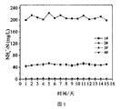
- FIG. 1 is a schematic diagram of a device for treating high ammonia nitrogen wastewater by e-SANI process
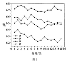
- FIG. 2 is a graph of pH change when using the e-SANI process to treat high ammonia nitrogen wastewater at -0.8V;
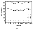
- FIG. 3 is a change diagram of NH4 + -N when e-SANI process is used to treat high ammonia nitrogen wastewater at -0.8V;
- FIG. 4 is a change diagram of NO3 -- N when using the e-SANI process to treat high ammonia nitrogen wastewater at -0.8V;
- FIG. 5 is a pH change diagram when a high ammonia nitrogen wastewater is treated by the e-SANI process at -0.9V;
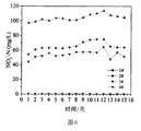
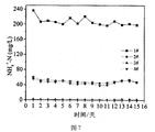
- FIG. 6 is a change diagram of NH4 + -N when e-SANI process is used to treat high ammonia nitrogen wastewater at -0.9V;
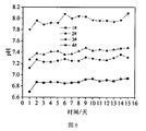
- FIG. 8 is a pH change diagram when a high ammonia nitrogen wastewater is treated by the e-SANI process at -1.0V;
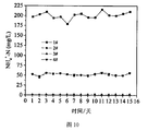
- Fig. 10 is a diagram showing the change of NO3 -- N when the high ammonia nitrogen wastewater is treated by the e-SANI process at -1.0V.
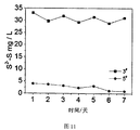
- FIG. 11 is a schematic diagram of a processing result of Embodiment 4.
- FIG. 11 is a schematic diagram of a processing result of Embodiment 4.
- the device using the microbial electrolytic cell to assist the SANI system for treating ammonia nitrogen wastewater includes a SANI system, 4 # chamber, 5 # chamber, and a power source.
- the 4 # chamber is a cathode chamber of the MEC
- the 5 # chamber is an anode of the MEC.
- the chamber is separated by a membrane between the 4 # chamber and the 5 # chamber; the cathode chamber and the anode chamber of the MEC are respectively connected to the negative electrode and the positive electrode of the power supply, and the cathode electrode in the cathode chamber is enriched with hydrogen.
- the process for treating ammonia nitrogen wastewater according to the present invention is as follows: the wastewater enters through the bottom of the sulfate reduction chamber of the SANI system, and the sulfate in the wastewater is reduced to negative divalent sulfur ions by sulfate reducing bacteria under complete mixing conditions.
- the electron source of the process is organic matter in the wastewater;
- the effluent from the sulfate reduction chamber reaches the sulfur autotrophic denitrification chamber of the SANI system, and the wastewater returned from the nitrification chamber is thoroughly mixed at the bottom of the sulfur autotrophic denitrification chamber; the nitrifying bacteria in the nitrification chamber will wastewater is converted into NH 4 + NO 3 -, NO 3 so there will be a large amount of sulfur autotrophic denitrification chamber - the presence of sulfur in the growth chamber autotrophic denitrification microorganisms under anaerobic conditions NO 3 -is converted into N 2 , and the electron source at this time is the negative divalent sulfur ion from the sulfate reduction chamber; the effluent from the sulfur autotrophic denitrification chamber enters the cathode chamber of the MEC, in order to avoid the cathode chamber The ion migration of the chamber and the anode chamber interferes with each other, so the membrane is used to isolate the negative and anode chambers; in the
- the wastewater treatment object is wastewater with NH4 + -N concentration of 214.6mg / L, SO 4 2- -S concentration of 200mg / L, and TOC concentration of 400mg / L.
- the initial pH was ⁇ 7.0.
- the wastewater treatment object is wastewater with NH4 + -N concentration of 214.6mg / L, SO 4 2- -S concentration of 200mg / L, and TOC concentration of 400mg / L.
- the initial pH was ⁇ 7.0.
- the wastewater treatment object is wastewater with NH4 + -N concentration of 214.6mg / L, SO 4 2- -S concentration of 200mg / L, and TOC concentration of 400mg / L.
- the initial pH was ⁇ 7.0.
- the wastewater treatment object is wastewater with NH4 + -N concentration of 214.6mg / L, SO 4 2- -S concentration of 200mg / L, and TOC concentration of 400mg / L.
- the initial pH was ⁇ 7.0.
Landscapes
- Life Sciences & Earth Sciences (AREA)
- Chemical & Material Sciences (AREA)
- Microbiology (AREA)
- Biodiversity & Conservation Biology (AREA)
- Hydrology & Water Resources (AREA)
- Engineering & Computer Science (AREA)
- Environmental & Geological Engineering (AREA)
- Water Supply & Treatment (AREA)
- Organic Chemistry (AREA)
- Health & Medical Sciences (AREA)
- Molecular Biology (AREA)
- Chemical Kinetics & Catalysis (AREA)
- Electrochemistry (AREA)
- General Chemical & Material Sciences (AREA)
- Water Treatment By Electricity Or Magnetism (AREA)
Abstract
一种利用微生物电解池(MEC)辅助SANI系统处理氨氮废水的装置,包括SANI系统、MEC的阴极腔室、MEC的阳极腔室和电源,阴极腔室和阳极腔室之间通过膜隔开;MEC的阴极腔室和阳极腔室分别与电源的负极和正极相连,阴极腔室内的阴极电极上富集有氢自养型反硝化细菌。SANI系统的硫自养反硝化腔室的出口与MEC的阴极腔室的入口相连,MEC阴极腔室的出口与SANI系统的硝化腔室的入口相连。还公开了一种利用微生物电解池(MEC)辅助SANI系统的装置处理氨氮废水的方法。
Description
本发明涉及一种利用微生物电解池辅助SANI系统处理氨氮废水的方法与装置,属于环境技术和水处理领域。
现如今,含氮废水的大量排放会极大地影响生态系统的平衡,对于水系中的影响尤甚,具有代表性的例子就是水体富营养化导致的赤潮等现象。传统的生物硝化反硝化过程在含氨处理中有着广泛的应用。尽管一些新颖的技术不断出现,例如A/O技术,但由于其具有低能耗高效率的优点,一直被使用着。可是,传统的硝化反硝化技术需要额外的投加碱度和电子给体,这就加大了整体的成本消耗。并且,传统的硝化反硝化过程是由异养反硝化菌消耗有机物进行的,因此会产生大量的污泥。
针对这两点,SANI工艺成功地解决了上述的问题,SANI工艺就是将硫还原、自养反硝化、硝化相结合的工艺,SANI工艺已经能在香港成功地对市政废水进行处理。然而,对于一些工业废水,例如石油废水,冶金废水,食品工业废水,制药废水等废水,其中的N浓度(氨浓度和硝酸盐浓度)要远远高于市政废水,针对这些废水,如果单纯使用SANI工艺进行脱氮,一则高氨氮的氧化会导致硝化腔室pH过低从而影响整个体系的脱氮效率,二则由于SANI体系S/N的要求导致需要有极高的S浓度。而在SANI工艺中增加进水中的S浓度是有着以下3个缺点:第一,高浓度的硫化物对微生物有毒害作用。第二,更高的S浓度会导致在硫还原过程中会产生更多的H
2S气体,所以在整个过程中也就会有更多的H
2S气体逸出。第三,更高的S浓度则是需要更多的操作成本。所以,想要用现阶段的SANI工艺来处理高氨氮的工业废水则需要对其进行一定的改进。
作为一种新兴的技术,微生物电解池(MEC)在水处理领域的应用在过去的十年中受到了大家广泛的研究。氢自养型反硝化细菌能够在MEC的阴极表面利用阴极产生的氢气进行反硝化,故此MEC阴极腔室能够充当二级反硝化腔室,从而间接降低SANI工艺进水中的S浓度。此外,MEC阴极发生产氢反应同时 会产生大量碱度,而硝化腔室发生的硝化反应过程产生大量的质子,条件合适,二者可以相互调节达到体系pH的长期稳定。因此,将MEC和SANI工艺相耦合的e-SANI工艺有望成为一项十分有前景的处理高氨氮废水的技术。
发明内容
本发明是将MEC和SANI工艺相耦合,强化SANI工艺使其能够适应对高氨氮含量的工艺废水的处理。利用MEC提供的额外电子和碱度,额外的进行反硝化过程同时调节硝化腔室的pH,达到了体系处理高氨氮废水的能力。
本发明的利用微生物电解池辅助SANI系统处理氨氮废水的装置包括SANI系统、4
#腔室、5
#腔室和电源,4
#腔室为MEC的阴极腔室,5
#腔室为MEC的阳极腔室,4
#腔室和5
#腔室之间通过膜隔开;MEC的阴极腔室和阳极腔室分别与电源的负极和正极相连,所述阴极腔室内的阴极电极上富集有氢自养型反硝化细菌;SANI系统的硫自养反硝化腔室的出口与MEC的阴极腔室的入口相连;MEC的阴极腔室的出口与SANI系统的硝化腔室的入口相连。
优选的,所述的SANI系统的硝化腔室的出口与MEC的阳极腔室相连。
优选的,所述的膜用于隔离阴阳极腔室,可以为质子交换膜,阳离子交换膜等。
进一步的,所述4
#腔室用石墨填料填充并用石墨棒引出连接电源,5
#腔室用DSA电极。
进一步的,所述的4
#腔室的条件是缺氧条件,溶解氧DO<0.5mg/L;5
#腔室为好氧条件,溶解氧DO>0.5mg/L;所述SANI系统、4
#腔室、5
#腔室都进行充分搅拌。
本发明还公开了一种所述装置的氨氮废水处理方法:废水经由SANI系统的硫酸盐还原腔室的底部进入,在完全混合的条件下,由硫酸盐还原菌将废水中的硫酸盐还原成负二价硫离子,此过程的电子来源为废水中的有机物;
硫酸盐还原腔室的出水到SANI系统的硫自养反硝化腔室之后,和从硝化腔室回流的废水在硫自养反硝化腔室底部进行充分混合;由于硝化腔室中的硝化细菌将废水中的NH
4
+转化成NO
3
-,所以在硫自养反硝化腔室中会有大量的NO
3
-存在,在腔室中生长的硫自养反硝化微生物在厌氧的条件下会将NO
3
-转化为N
2,而此时的电子来源是硫酸盐还原腔室中过来的负二价硫离子;硫自养反硝化腔室 的出水进入MEC的阴极腔室,为了避免阴极腔室和阳极腔室的离子迁移相互干扰故采用膜隔离阴阳极腔室;在阴极腔室中氢自养型反硝化菌进行深度反硝化进一步脱氮,然后,阴极腔室出水再经上部出口流至硝化腔室以将水中的NH
4
+转化成NO
3
-;此外,在阴极腔室里伴随着产氢反应产生的大量的氢氧根能够有效中和硝化腔室里硝化过程上产生的大量质子;最后硝化腔室出水直接排放或者打入MEC的阳极腔室进行氧化处理掉水中的负二价硫后直接排放。
进一步的,所述的硝化腔室中排水量与回流到硫自养反硝化腔室的水量的流量比为1:0.5~1:5。
进一步的,所述的SANI系统、4
#腔室和5
#腔室的温度控制在25±5℃,每个腔室的水力停留时间为18~36h。
进一步的,所述的阴极电势范围为:-0.4V~-1.2V。
进一步的,所述的阳极电势为:0.5V~2.3V。
本发明与现有技术相比,所具有的有益效果是:
1)能够应用处理高氨氮(≥200mg NH
4
+-N/L)废水;
2)能够达到自身酸碱度调节,无需额外投加碱度或酸度;
3)脱氮效率更高;
4)利用微生物电解池阳极腔室对出水中负二价硫进一步氧化脱除。
图1为用e-SANI工艺处理高氨氮废水的装置示意图;
图2为用e-SANI工艺在-0.8V时处理高氨氮废水时pH变化图;
图3为用e-SANI工艺在-0.8V时处理高氨氮废水时NH4
+-N变化图;
图4为用e-SANI工艺在-0.8V时处理高氨氮废水时NO3
--N变化图;
图5为用e-SANI工艺在-0.9V时处理高氨氮废水时pH变化图;
图6为用e-SANI工艺在-0.9V时处理高氨氮废水时NH4
+-N变化图;
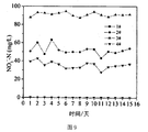
图7为用e-SANI工艺在-0.9V时处理高氨氮废水时NO3
--N变化图;
图8为用e-SANI工艺在-1.0V时处理高氨氮废水时pH变化图;
图9为用e-SANI工艺在-1.0V时处理高氨氮废水时NH4
+-N变化图;
图10为用e-SANI工艺在-1.0V时处理高氨氮废水时NO3 --N变化图。
[根据细则26改正05.11.2018]
图11为实施例4的处理结果示意图。
图11为实施例4的处理结果示意图。
为了更好的理解本发明,下面通过附图以及具体实施来做进一步说明。
参照图1,整个装置是连续流操作。本发明的利用微生物电解池辅助SANI系统处理氨氮废水的装置包括SANI系统、4
#腔室、5
#腔室和电源,4
#腔室为MEC的阴极腔室,5
#腔室为MEC的阳极腔室,4
#腔室和5
#腔室之间通过膜隔开;MEC的阴极腔室和阳极腔室分别与电源的负极和正极相连,所述阴极腔室内的阴极电极上富集有氢自养型反硝化细菌;SANI系统的硫自养反硝化腔室的出口与MEC的阴极腔室的入口相连;MEC的阴极腔室的出口与SANI系统的硝化腔室的入口相连。
本发明处理氨氮废水的流程如下:废水经由SANI系统的硫酸盐还原腔室的底部进入,在完全混合的条件下,由硫酸盐还原菌将废水中的硫酸盐还原成负二价硫离子,此过程的电子来源为废水中的有机物;
硫酸盐还原腔室的出水到SANI系统的硫自养反硝化腔室之后,和从硝化腔室回流的废水在硫自养反硝化腔室底部进行充分混合;由于硝化腔室中的硝化细菌将废水中的NH
4
+转化成NO
3
-,所以在硫自养反硝化腔室中会有大量的NO
3
-存在,在腔室中生长的硫自养反硝化微生物在厌氧的条件下会将NO
3
-转化为N
2,而此时的电子来源是硫酸盐还原腔室中过来的负二价硫离子;硫自养反硝化腔室的出水进入MEC的阴极腔室,为了避免阴极腔室和阳极腔室的离子迁移相互干扰故采用膜隔离阴阳极腔室;在阴极腔室中氢自养型反硝化菌进行深度反硝化进一步脱氮,然后,阴极腔室出水再经上部出口流至硝化腔室以将水中的NH
4
+转化成NO
3
-;此外,在阴极腔室里伴随着产氢反应产生的大量的氢氧根能够有效中和硝化腔室里硝化过程上产生的大量质子;最后硝化腔室出水直接排放或者打入MEC的阳极腔室进行氧化处理掉水中的负二价硫后直接排放。
实施例1
废水处理对象为NH4
+-N浓度为214.6mg/L,SO
4
2--S浓度为200mg/L的废水,TOC浓度为400mg/L。初始pH是~7.0。
回流比控制在回流/出水=3:1,每个腔室水力停留时间控制在24h,系统运行温度控制在25±5℃,阴极电势分别控制在-0.8V.
结果如图2-4所示,在引入MEC之后,3#硝化腔室pH能稳定在6.2~6.3之间,氨氮几乎为0,这说明pH的改善极大地提高了硝化效率。但2#与4#的NO
3
--N几乎一致,这说明4#腔室的脱氮效果还不是很明显,有待继续优化。
实施例2
废水处理对象为NH4
+-N浓度为214.6mg/L,SO
4
2--S浓度为200mg/L的废水,TOC浓度为400mg/L。初始pH是~7.0。
回流比控制在回流/出水=3:1,每个腔室水力停留时间控制在24h,系统运行温度控制在25±5℃,阴极电势分别控制在-0.9V。
结果如图5-7所示,在阴极电势由-0.8V提高到-0.9V之后,2#,3#和4#腔室pH均稳定提升,以至出水pH能稳定在6.8~7.0之间,这与进水pH相差无几,这意味着在阴极电势为-0.9V条件下,能使整个体系自身现实酸碱度调节达到进出水pH一致。出水氨氮几乎为0,硝化效率稳定在99%左右。2#与4#的NO
3
—N差距开始体现,这说明4#腔室的脱氮效果开始体现,但仍有待继续优化的空间。
实施例3
废水处理对象为NH4
+-N浓度为214.6mg/L,SO
4
2--S浓度为200mg/L的废水,TOC浓度为400mg/L。初始pH是~7.0。
回流比控制在回流/出水=3:1,每个腔室水力停留时间控制在24h,系统运行温度控制在25±5℃,阴极电势分别控制在-1.0V
结果如图8-10所示,在阴极电势进一步由-0.9V提高到-1.0V之后,2#,3#和4#腔室pH进一步提升,以至出水pH能稳定在7.0~7.2之间,出水氨氮几乎为0,硝化效率稳定在99%左右。2#与4#的NO
3
--N差距较-0.9V条件下进一步加大,这说明4#腔室的脱氮效果随着阴极电势的提高而增强,但4#腔室pH已经接近8.0左右,因此阴极电势的进一步提升得考虑4#腔室pH的问题。
实施例4
废水处理对象为NH4
+-N浓度为214.6mg/L,SO
4
2--S浓度为200mg/L的废水,TOC浓度为400mg/L。初始pH是~7.0。
回流比控制在回流/出水=3:1,每个腔室水力停留时间控制在24h,系统运行温度控制在25±5℃,阴极电势分别控制在-0.9V,出水打入MEC阳极腔室 (5#腔室)进行深度硫化物氧化脱除。
结果如图11所示,出水经5#腔室进一步氧化处理之后,硫化物能从30mg/L降到1~2mg/L,效果显著。
Claims (9)
- 一种利用微生物电解池辅助SANI系统处理氨氮废水的装置,其特征在于:包括SANI系统、4 #腔室、5 #腔室和电源,4 #腔室为MEC的阴极腔室,5 #腔室为MEC的阳极腔室,4 #腔室和5 #腔室之间通过膜隔开;MEC的阴极腔室和阳极腔室分别与电源的负极和正极相连,所述阴极腔室内的阴极电极上富集有氢自养型反硝化细菌;SANI系统的硫自养反硝化腔室的出口与MEC的阴极腔室的入口相连;MEC的阴极腔室的出口与SANI系统的硝化腔室的入口相连。
- 根据权利要求1所述的处理氨氮废水的装置,其特征在于所述的SANI系统的硝化腔室的出口与MEC的阳极腔室相连。
- 根据权利要求1所述的处理氨氮废水的装置,其特征在于所述4 #腔室用石墨填料填充并用石墨棒引出连接电源,5 #腔室用DSA电极。
- 根据权利要求1所述的处理氨氮废水的装置,其特征在于所述的4 #腔室的条件是缺氧条件,溶解氧DO<0.5mg/L;5 #腔室为好氧条件,溶解氧DO>0.5mg/L;所述SANI系统、4 #腔室、5 #腔室都进行充分搅拌。
- 一种如权利要求1所述装置的氨氮废水处理方法,其特征在于:废水经由SANI系统的硫酸盐还原腔室的底部进入,在完全混合的条件下,由硫酸盐还原菌将废水中的硫酸盐还原成负二价硫离子,此过程的电子来源为废水中的有机物;硫酸盐还原腔室的出水到SANI系统的硫自养反硝化腔室之后,和从硝化腔室回流的废水在硫自养反硝化腔室底部进行充分混合;由于硝化腔室中的硝化细菌将废水中的NH 4 +转化成NO 3 -,所以在硫自养反硝化腔室中会有大量的NO 3 -存在,在腔室中生长的硫自养反硝化微生物在厌氧的条件下会将NO 3 -转化为N 2,而此时的电子来源是硫酸盐还原腔室中过来的负二价硫离子;硫自养反硝化腔室的出水进入MEC的阴极腔室,为了避免阴极腔室和阳极腔室的离子迁移相互干扰故采用膜隔离阴阳极腔室;在阴极腔室中氢自养型反硝化菌进行深度反硝化进一步脱氮,然后,阴极腔室出水再经上部出口流至硝化腔室以将水中的NH 4 +转化成NO 3 -;此外,在阴极腔室里伴随着产氢反应产生的大量的氢氧根能够有效中和硝化腔室里硝化过程上产生的大量质子;最后硝化腔室出水直接排放或者打入MEC的阳极腔室进行氧化处理掉水中的负二价硫后直接排放。
- 根据权利要求5所述的方法,其特征在于所述的硝化腔室中排水量与回流到硫自养反硝化腔室的水量的流量比为1:0.5~1:5。
- 根据权利要求5所述的方法,其特征在于所述的SANI系统、4 #腔室和5 #腔室的温度控制在25±5℃,每个腔室的水力停留时间为18~36h。
- 根据权利要求5所述的方法,其特征在于所述的阴极电势范围为:-0.4V~-1.2V。
- 根据权利要求8所述的方法,其特征在于所述的阳极电势为:0.5V~2.3V。
Priority Applications (1)
| Application Number | Priority Date | Filing Date | Title |
|---|---|---|---|
| US17/055,998 US11401185B2 (en) | 2018-09-12 | 2018-10-16 | Method and device for treating ammonia-nitrogen wastewater using microbial electrolysis cell assisted SANI system |
Applications Claiming Priority (2)
| Application Number | Priority Date | Filing Date | Title |
|---|---|---|---|
| CN201811059860.7A CN109179684B (zh) | 2018-09-12 | 2018-09-12 | 利用微生物电解池辅助sani系统处理氨氮废水的方法与装置 |
| CN201811059860.7 | 2018-09-12 |
Publications (1)
| Publication Number | Publication Date |
|---|---|
| WO2020051969A1 true WO2020051969A1 (zh) | 2020-03-19 |
Family
ID=64910301
Family Applications (1)
| Application Number | Title | Priority Date | Filing Date |
|---|---|---|---|
| PCT/CN2018/110409 Ceased WO2020051969A1 (zh) | 2018-09-12 | 2018-10-16 | 利用微生物电解池辅助sani系统处理氨氮废水的方法与装置 |
Country Status (3)
| Country | Link |
|---|---|
| US (1) | US11401185B2 (zh) |
| CN (1) | CN109179684B (zh) |
| WO (1) | WO2020051969A1 (zh) |
Cited By (3)
| Publication number | Priority date | Publication date | Assignee | Title |
|---|---|---|---|---|
| CN112250162A (zh) * | 2020-10-09 | 2021-01-22 | 哈尔滨工业大学 | 微生物电解池耦合BAF-MBfR的低C/N污水深度脱氮装置和脱氮方法 |
| IT202000014881A1 (it) | 2020-06-22 | 2021-12-22 | Mt Ortho S R L | Granulo cilindrico in materiale metallico biocompatibile per vertebroplastica |
| CN119390247A (zh) * | 2024-11-22 | 2025-02-07 | 重庆阁林环保科技有限公司 | 基于硫自养反硝化的可对硫资源化利用的污水处理系统 |
Families Citing this family (8)
| Publication number | Priority date | Publication date | Assignee | Title |
|---|---|---|---|---|
| CN111115847B (zh) * | 2019-12-30 | 2021-04-13 | 浙江大学 | 一种基于电化学硫酸盐循环的脱氮方法与装置 |
| CN111573822A (zh) * | 2020-05-22 | 2020-08-25 | 盐城工学院 | 一种高氨氮高硫酸盐废水的生物电化学处理工艺 |
| CN113716690A (zh) * | 2021-08-23 | 2021-11-30 | 河北科技大学 | 硫自养反硝化深度脱氮工艺及装置 |
| CN114772747B (zh) * | 2022-04-20 | 2023-10-27 | 同济大学 | 一种氨氮废水脱氮处理系统及方法 |
| CN115043483B (zh) * | 2022-06-21 | 2024-01-12 | 河南工业大学 | 一种去除水体中硝酸盐的升流穿越式生物电化学反应系统 |
| CN119019009B (zh) * | 2023-05-25 | 2026-07-03 | 香港科技大学 | 废水处理方法和废水处理系统 |
| CN117125807B (zh) * | 2023-09-13 | 2025-09-30 | 中国科学院生态环境研究中心 | 基于微生物电解池实现亚硝化的污水处理系统及方法 |
| CN120518246B (zh) * | 2025-05-23 | 2026-07-17 | 广东微乐环保成套设备有限公司 | 一种基于脱硫脱氮的污水处理方法 |
Citations (4)
| Publication number | Priority date | Publication date | Assignee | Title |
|---|---|---|---|---|
| CN104743663A (zh) * | 2015-03-20 | 2015-07-01 | 浙江工商大学 | 利用高有机物高氨氮废水强化产甲烷的生物电化学反应装置和方法 |
| CN105084530A (zh) * | 2014-05-16 | 2015-11-25 | 中国科学院生态环境研究中心 | 一种电化学辅助生物脱氮技术 |
| CN105217796A (zh) * | 2015-11-04 | 2016-01-06 | 中国科学院水生生物研究所 | 一种下行垂直流人工湿地耦合微生物电解池强化脱氮的方法及装置 |
| EP2925679B1 (en) * | 2012-11-28 | 2018-06-06 | Universitat de Girona | Bioelectrochemical water treatment and apparatus |
Family Cites Families (5)
| Publication number | Priority date | Publication date | Assignee | Title |
|---|---|---|---|---|
| EP2595925A4 (en) * | 2010-07-21 | 2014-08-27 | Cambrian Innovation Llc | DENITRIFICATION AND PH CONTROL USING BIO-ELECTROCHEMICAL SYSTEMS |
| WO2012071793A1 (en) * | 2010-12-02 | 2012-06-07 | The Hong Kong University Of Science And Technology | Biological wastewater treatment and reuse utilizing sulfur compounds as electron carrier to minimize sludge production |
| CN103539314A (zh) * | 2013-09-25 | 2014-01-29 | 安徽省绿巨人环境技术有限公司 | 一种高浓度、难降解、有毒有害有机工业废水处理工艺及装置 |
| WO2016112835A1 (en) * | 2015-01-14 | 2016-07-21 | The Hong Kong University Of Science And Technology | Internal sulfur cycling sani (isc-sani) process for biological wastewater treatment |
| CN105032152B (zh) * | 2015-07-24 | 2017-10-17 | 大连理工大学 | 一种化学吸收结合微生物燃料电池同步烟气脱硫脱硝的工艺 |
-
2018
- 2018-09-12 CN CN201811059860.7A patent/CN109179684B/zh active Active
- 2018-10-16 US US17/055,998 patent/US11401185B2/en active Active
- 2018-10-16 WO PCT/CN2018/110409 patent/WO2020051969A1/zh not_active Ceased
Patent Citations (4)
| Publication number | Priority date | Publication date | Assignee | Title |
|---|---|---|---|---|
| EP2925679B1 (en) * | 2012-11-28 | 2018-06-06 | Universitat de Girona | Bioelectrochemical water treatment and apparatus |
| CN105084530A (zh) * | 2014-05-16 | 2015-11-25 | 中国科学院生态环境研究中心 | 一种电化学辅助生物脱氮技术 |
| CN104743663A (zh) * | 2015-03-20 | 2015-07-01 | 浙江工商大学 | 利用高有机物高氨氮废水强化产甲烷的生物电化学反应装置和方法 |
| CN105217796A (zh) * | 2015-11-04 | 2016-01-06 | 中国科学院水生生物研究所 | 一种下行垂直流人工湿地耦合微生物电解池强化脱氮的方法及装置 |
Cited By (3)
| Publication number | Priority date | Publication date | Assignee | Title |
|---|---|---|---|---|
| IT202000014881A1 (it) | 2020-06-22 | 2021-12-22 | Mt Ortho S R L | Granulo cilindrico in materiale metallico biocompatibile per vertebroplastica |
| CN112250162A (zh) * | 2020-10-09 | 2021-01-22 | 哈尔滨工业大学 | 微生物电解池耦合BAF-MBfR的低C/N污水深度脱氮装置和脱氮方法 |
| CN119390247A (zh) * | 2024-11-22 | 2025-02-07 | 重庆阁林环保科技有限公司 | 基于硫自养反硝化的可对硫资源化利用的污水处理系统 |
Also Published As
| Publication number | Publication date |
|---|---|
| US11401185B2 (en) | 2022-08-02 |
| CN109179684A (zh) | 2019-01-11 |
| US20210206674A1 (en) | 2021-07-08 |
| CN109179684B (zh) | 2020-05-22 |
Similar Documents
| Publication | Publication Date | Title |
|---|---|---|
| US11401185B2 (en) | Method and device for treating ammonia-nitrogen wastewater using microbial electrolysis cell assisted SANI system | |
| CN108483655B (zh) | 一种短程硝化反硝化耦合厌氧氨氧化和硫自养反硝化深度脱氮的方法 | |
| CN110642474B (zh) | 一种厌氧-ao-sacr组合式高氨氮污水深度脱氮系统及工艺 | |
| CN102633359B (zh) | 一种适用于含氮化工废水总氮的处理方法 | |
| CN101353203B (zh) | 一种短程脱氮同步反硝化除磷的工艺及装置 | |
| CN111115847B (zh) | 一种基于电化学硫酸盐循环的脱氮方法与装置 | |
| CN107988132A (zh) | 一种耐硫酸盐型厌氧氨氧化菌的驯化方法 | |
| CN105293826B (zh) | 一种反硫化厌氧氨氧化高效除硫脱氮方法 | |
| CN110759593A (zh) | 一种分段进水多级a/o处理焦化废水的工艺 | |
| CN106542636B (zh) | 一种快速启动全程自养脱氮的方法 | |
| CN106082427A (zh) | 一种同步去除硝酸盐和六价铬的电极生物膜反应器 | |
| CN108946927B (zh) | 一种实现污水亚硝酸盐累积的污泥快速培养方法 | |
| CN107840550B (zh) | 一种垃圾渗沥液的处理方法 | |
| CN105366887B (zh) | 炼油厂废水综合处理工艺 | |
| CN110606626A (zh) | 一种同步脱氮除磷污水处理工艺 | |
| CN110054284A (zh) | 城市污水处理的半亚硝化工艺启动与控制方法 | |
| CN104591401B (zh) | 一种用于同步脱氮除碳的滴滤式生物阴极微生物电化学系统 | |
| CN107840444B (zh) | 一种垃圾渗沥液的处理装置 | |
| CN110759604A (zh) | 一种低碳源污水两级sbr串联高效生物脱氮方法 | |
| CN111573822A (zh) | 一种高氨氮高硫酸盐废水的生物电化学处理工艺 | |
| CN105174464A (zh) | 一种电辅助微生物反应器去除氨氮废水的方法 | |
| CN108033600A (zh) | 一种高浓高毒农药废水的集成预处理方法及应用 | |
| CN103214103B (zh) | 一种廊道推流式反应器实现生活污水半亚硝化的方法 | |
| CN206544937U (zh) | 一种双泥同步硝化反硝化脱氮产电装置 | |
| CN104925946A (zh) | 反硝化除磷产电装置 |
Legal Events
| Date | Code | Title | Description |
|---|---|---|---|
| 121 | Ep: the epo has been informed by wipo that ep was designated in this application |
Ref document number: 18933098 Country of ref document: EP Kind code of ref document: A1 |
|
| NENP | Non-entry into the national phase |
Ref country code: DE |
|
| 122 | Ep: pct application non-entry in european phase |
Ref document number: 18933098 Country of ref document: EP Kind code of ref document: A1 |