WO2020050387A1 - Binding machine - Google Patents
Binding machine Download PDFInfo
- Publication number
- WO2020050387A1 WO2020050387A1 PCT/JP2019/035091 JP2019035091W WO2020050387A1 WO 2020050387 A1 WO2020050387 A1 WO 2020050387A1 JP 2019035091 W JP2019035091 W JP 2019035091W WO 2020050387 A1 WO2020050387 A1 WO 2020050387A1
- Authority
- WO
- WIPO (PCT)
- Prior art keywords
- grip
- grips
- pair
- binding machine
- axis
- Prior art date
Links
Images


Classifications
-
- E—FIXED CONSTRUCTIONS
- E04—BUILDING
- E04G—SCAFFOLDING; FORMS; SHUTTERING; BUILDING IMPLEMENTS OR AIDS, OR THEIR USE; HANDLING BUILDING MATERIALS ON THE SITE; REPAIRING, BREAKING-UP OR OTHER WORK ON EXISTING BUILDINGS
- E04G21/00—Preparing, conveying, or working-up building materials or building elements in situ; Other devices or measures for constructional work
- E04G21/12—Mounting of reinforcing inserts; Prestressing
- E04G21/122—Machines for joining reinforcing bars
- E04G21/123—Wire twisting tools
-
- B—PERFORMING OPERATIONS; TRANSPORTING
- B65—CONVEYING; PACKING; STORING; HANDLING THIN OR FILAMENTARY MATERIAL
- B65B—MACHINES, APPARATUS OR DEVICES FOR, OR METHODS OF, PACKAGING ARTICLES OR MATERIALS; UNPACKING
- B65B13/00—Bundling articles
- B65B13/18—Details of, or auxiliary devices used in, bundling machines or bundling tools
- B65B13/24—Securing ends of binding material
- B65B13/28—Securing ends of binding material by twisting
- B65B13/285—Hand tools
-
- B—PERFORMING OPERATIONS; TRANSPORTING
- B25—HAND TOOLS; PORTABLE POWER-DRIVEN TOOLS; MANIPULATORS
- B25B—TOOLS OR BENCH DEVICES NOT OTHERWISE PROVIDED FOR, FOR FASTENING, CONNECTING, DISENGAGING OR HOLDING
- B25B25/00—Implements for fastening, connecting or tensioning of wire or strip
-
- B—PERFORMING OPERATIONS; TRANSPORTING
- B65—CONVEYING; PACKING; STORING; HANDLING THIN OR FILAMENTARY MATERIAL
- B65B—MACHINES, APPARATUS OR DEVICES FOR, OR METHODS OF, PACKAGING ARTICLES OR MATERIALS; UNPACKING
- B65B13/00—Bundling articles
- B65B13/18—Details of, or auxiliary devices used in, bundling machines or bundling tools
- B65B13/185—Details of tools
- B65B13/187—Motor means
-
- E—FIXED CONSTRUCTIONS
- E04—BUILDING
- E04G—SCAFFOLDING; FORMS; SHUTTERING; BUILDING IMPLEMENTS OR AIDS, OR THEIR USE; HANDLING BUILDING MATERIALS ON THE SITE; REPAIRING, BREAKING-UP OR OTHER WORK ON EXISTING BUILDINGS
- E04G21/00—Preparing, conveying, or working-up building materials or building elements in situ; Other devices or measures for constructional work
- E04G21/12—Mounting of reinforcing inserts; Prestressing
-
- B—PERFORMING OPERATIONS; TRANSPORTING
- B65—CONVEYING; PACKING; STORING; HANDLING THIN OR FILAMENTARY MATERIAL
- B65B—MACHINES, APPARATUS OR DEVICES FOR, OR METHODS OF, PACKAGING ARTICLES OR MATERIALS; UNPACKING
- B65B13/00—Bundling articles
- B65B13/18—Details of, or auxiliary devices used in, bundling machines or bundling tools
- B65B13/24—Securing ends of binding material
- B65B13/28—Securing ends of binding material by twisting
Definitions
- the present invention relates to a binding machine that binds a binding object such as a reinforcing bar with a wire such as a wire.
- the handle is connected to another part of the machine via a telescopic part in order to change the position of the handle.
- the entire length of the machine that is, the extension and contraction adjustment of the length from the guide portion to the handle is performed by changing the length of the telescopic portion according to the corresponding work and the height of the operator.
- the internal wiring processing may be complicated, and the electrical efficiency may be deteriorated due to the extension of the wire length.
- a method of exchanging a portion that connects a handle portion and a binding device main body portion having a torsion portion or the like can be considered. Since it is necessary to remove the connecting portion from the binding device main body and reassemble the connecting portion, the handle portion, and the binding device main portion having different lengths, the replacement operation is complicated, and there is a possibility of erroneous assembly. Further, when the electric wiring is arranged inside or on the outer peripheral portion of the connecting portion, there is a possibility that a trouble such as disconnection due to disconnection and reconnection of the wiring may occur.
- the present invention solves such a problem, and does not extend the connecting portion, and extends the entire length of the binding machine, that is, from the guide portion to the grip position of the handle, according to the physique of the operator and the use condition of the binding machine. It is an object of the present invention to provide a binding machine capable of changing the length of the binding device.
- a binding machine has a first main body and an opening through which a binding target can be inserted, and curls a wire along the periphery of the binding target inserted into the opening.
- the pair of grips are provided on both sides of the axis of the torsion axis when viewed from the operator side when the operator grips and operates the pair of grips, and the position of the pair of grips can be changed in the axial direction of the torsion axis. By doing so, it is possible to adjust the overall length of the binding machine according to the physique of the operator and the use condition of the binding machine without extending the connecting portion.
- Another aspect of the binding machine according to the present invention is a binding machine in which the pair of grips are arranged such that the axes of the pair of grips are orthogonal or substantially orthogonal to the axis of the torsion axis.
- the entire length of the binding machine can be adjusted without changing the length of the connecting portion by changing the grip position of the handle in the torsion axis direction according to the physique and the use condition of the operator.
- FIG. 3 is a side view illustrating a configuration of a main part of a second main body according to the first embodiment.
- FIG. 3 is a perspective view illustrating a configuration of a main part of a first main body according to the first embodiment. It is a front view showing the example of composition which makes the grip height of the reinforcing bar binding machine concerning a 1st embodiment variable. It is a front view showing the example of composition which makes the grip height of the reinforcing bar binding machine concerning a 1st embodiment variable. It is a perspective view showing the appearance composition of the rebar tying machine concerning a 2nd embodiment. It is a side view which shows the external appearance structure of the rebar binding machine which concerns on 2nd Embodiment. It is a perspective view showing the appearance composition of the rebar tying machine concerning a 3rd embodiment.
- FIG. 1 is a side view showing an internal configuration of the reinforcing bar binding machine 1A according to the first embodiment
- FIG. 2 is a side view showing an external configuration of the reinforcing bar binding machine 1A
- FIG. 6 is a side view showing a main part configuration of a second main body part of the reinforcing bar binding machine 1A according to the first embodiment
- FIG. 7 is a perspective view showing a main part configuration of the first main body part
- 8 and 9 are front views showing a configuration example in which the grip height of the reinforcing bar binding machine 1A according to the first embodiment is variable.
- a symbol indicating a portion or the like located on the left hand side of the operator is denoted by “L”
- a symbol indicating a portion or the like located on the right hand side is denoted by “R”.
- the description will be made with ".”
- the handle 122L is a handle on the left hand side of the operator
- the handle 122R is a handle on the right hand side of the operator.
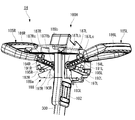
- the rebar tying machine 1A has a first main body 100 having a pair of grips 120L and 120R that can be gripped by an operator, and an opening through which a tying object can be inserted, and a periphery of the tying object inserted into the opening.
- a second main body 200 having a curl guide 230A for curling the wire W along the periphery of the object to be bound along the twisted portion 250 for twisting the wire W curled by the curl guide 230A, and a first main body.
- 100 includes a connecting portion 300 for connecting the second main body 200 to the second main body 200.
- the axis of the torsion shaft 253 rotated by the rotation of the torsion motor 251 disposed in the torsion portion 250 of the second main body 200 is denoted by A1.
- the axis of the connecting portion 300 is A2.
- the axes of the grip 120L held by the operator with the left hand and the grip 120R held by the right hand are referred to as a grip axis A3L and a grip axis A3R, respectively.
- the side on which the curl guide 230 is provided is the tip side or lower side of the reinforcing bar binding machine 1A, and the opposite side, that is, the end side of the first main body 100 is the base of the reinforcing bar binding machine 1A. End or top.
- the rebar tying machine 1A has a configuration in which the second main body 200, the connecting portion 300, and the first main body 100 are arranged in order from the lower side to the upper side.
- the side on which the operator holding the grip 120L and the grip 120R stands is the back side of the reinforcing bar binding machine 1A, and the opposite side is the front side of the reinforcing bar binding machine 1A.
- the side where the grip 120L and the grip 120R are located is defined as the side of the reinforcing bar binding machine 1A
- the grip 120R side is defined as the right side of the reinforcing bar binding machine 1A
- the grip 120L side is defined as the left side of the reinforcing bar binding machine 1A.
- the first main body 100 includes handle portions 122L and 122R each having a pair of grips 120L and 120R, a grip mounting portion 130 having a plurality of grooves to which the handle portions 122L and 122R can be mounted, and an elongated connecting portion 300.
- the first housing 102 supports the upper end of the battery, and a battery mounting portion 140 to which a battery 142 as a power supply is detachably mounted.
- the first housing 102 has a distal end connected to the connecting portion 300, and a proximal end provided with a setting portion 144 for setting various operating conditions of the reinforcing bar binding machine 1A.
- the handle portions 122L and 122R are formed of a U-shaped or M-shaped long member when viewed from the axial direction D3 of the connecting portion 300. At least one of the grips 120L, 120R is provided with an operation switch 146 (see FIG. 1) for starting a binding operation.
- the handle portion 122L includes the grip 120L and the grip connecting portion 121L
- the handle portion 122R includes the grip 120R and the grip connecting portion 121R.
- the grips 120L and 120R are attached to the grip attachment section 130 via the grip connection sections 121L and 121R, respectively (see FIG. 7A).
- the handle portions 122L and 122R may adopt various shapes such as a straight shape when viewed from the axial direction D3 of the connecting portion 300, or a U shape or an M shape when viewed from the front or back direction. Can be.
- the grips 120L and 120R are provided on both sides of the axis A1 of the torsion shaft 253 when viewed from the operator side. 253 in the direction of the axis A1.
- the grip axes A3L, A3R (not shown) and the axis A1 of the torsion shaft 253 are orthogonal or substantially orthogonal. Is preferred. However, the present invention is not limited to this, and the grip axes A3L and A3R have an angle that is substantially orthogonal or more upward or downward with respect to the axis A1 of the torsion axis 253, for example, an angle of 5 degrees or more. Is also good.
- the angles of the grip axes A3L and A3R with respect to the direction of gravity can also be adjusted as appropriate by changing the connection angle between the grips 120L and R and the grip connection portions 121L and R.
- the grip mounting portion 130 is formed in a substantially rectangular parallelepiped shape, and is mounted on the front side of the first housing 102. Each of the upper, lower, left and right side surfaces of the grip mounting portion 130 is provided with a mounting mechanism for mounting a handle portion 122L, 122R having a pair of grips 120L, 120R, respectively.
- the attachment mechanism for example, the grip attachment portion 130 is constituted by a pair of attachment members, a plurality of grooves for fitting the grips 120R, 120L is formed on the opposing surface of each attachment member, and the grip connection portions 121R, 121L are formed in each groove.
- the grips 120 ⁇ / b> R and 120 ⁇ / b> L can be fixed to the grip mounting portion 130 by being fitted and sandwiched between a pair of mounting members. Of course, other known mounting mechanisms may be employed.
- handle parts 122L and 122R each having a pair of grips 120L and 120R may be attached to the first housing 102 without providing the grip attaching part 130 on the first main body 100.
- the first housing 102 may be provided with an attachment mechanism including a plurality of grooves.
- the battery mounting part 140 is provided on the first housing 102 so as to be located above the handle parts 122L and 122R.
- the battery mounting part 140 is disposed on an extension of the axis A2 of the connecting part 300.
- the setting unit 144 is a unit for adjusting the number of turns of the wire W and the torsion torque of the wire W, and is configured by, for example, a dial-type or push-button-type switch (see FIGS. 1 and 2).
- the grip height H the height up to the grip axis A ⁇ b> 3 ⁇ / b> L with the bar arrangement surface F being the lower reference position of the grip height H and the upper reference position is shown as the grip height H.
- the rebar arrangement surface F means a surface on which the binding target object is disposed, and is located, for example, as shown by a dotted line in FIG. What is necessary is just to make the surface which connects between the center of the cross section of a reinforcing bar.
- the reference position on the upper side of the grip height H is the position on the grip axis A3L as shown by a dotted line in FIG. It is preferred to do so.
- the axis A1 of the grip axes A3L, A3R and the axis A1 of the torsion axis 253 are not orthogonal or substantially orthogonal, any point on the grip axes A3L, A3R, for example, the center position is set as the upper reference position of the grip height H. I just need.
- the second main body 200 includes a second housing 202, a reel housing 210 that houses a wire reel 211 around which the wire W is wound, and a wire reel 211 that is housed in the reel housing 210.
- a wire feeder 220 that pulls out the wire W from the wire feeder, a curl guide 230A that curls the wire W along the periphery of the object to be bound, and a cutting unit that cuts the wire W curled by the curl guide 230A 240, and a torsion part 250 for curling the wire W curled by the curl guide 230A and cut by the cutting part 240.
- a curl guide 230 ⁇ / b> A is provided at a distal end of the second housing 202, and a wire feeding unit 220, a cutting unit, and a twisting unit 250 are housed inside the second housing 202.
- the second main body 200 includes a contact member 233 that activates a second guide 232A, which will be described later, of the curl guide 230A when the rebar S comes into contact therewith, and a cover that covers the lower end of the second housing 202. 206.
- the wire feeder 220 is provided between the reel housing 210 and the curl guide 230A, and has a pair of feed gears for feeding a wire.
- the pair of feed gears of the wire feed unit 220 are configured to be able to rotate forward and reverse by driving a motor (not shown). Accordingly, when the feed gear is rotated forward, the wire W can be sent to the curl guide 230A side, and when the feed gear is rotated reversely, the wire W can be pulled back to the reel housing portion 210 side.
- the curl guide 230A has an opening 260 into which the reinforcing bar S can be inserted, and curls the wire W around the reinforcing bar S inserted into the opening 260.
- the curl guide 230A is provided so as to protrude further forward (the first direction D1 which is a plane direction of the first main body) from the tip of the second housing 202, and has a pair of guides, that is, a first guide 231A and a second guide. It is constituted by a guide portion 232A.
- the first guide portion 231A and the second guide portion 232A are arranged at a predetermined interval L forming the opening 260 in a second direction D2 orthogonal to the first direction D1.
- the first guide portion 231 ⁇ / b> A regulates the traveling direction of the wire W sent from the wire sending portion 220 and adds a curl to the wire W.
- the second guide portion 232A receives the wire W curled by the first guide portion 231A and guides the wire W to the torsion portion 250.
- the rebar S is inserted into the opening between the first guide portion 231A and the second guide portion 232A.
- the cover 206 is made of a metal plate or the like, and is formed between the base end of the first guide 231A and the base end of the second guide 232A. Attached so as to cover the lower end of the second housing 202.
- the contact member 233 is rotatably supported by a shaft 236 attached to the cover portion 206.
- the contact member 233 is a dog-leg-shaped member, and one of the first guide portions sandwiching the shaft 236.
- a pair of abutting portions 234 (only one abutting portion is shown in FIGS. 6A and 6B) where the reinforcing bar S abuts on the 231A side, and a pressing portion 235 extending toward the second guide portion 232A.
- the contact portion 234 is arranged at a position where the reinforcing bar S inserted into the opening 260 can contact, and the pressing portion 235 is in contact with the second guide portion 232A.
- the contact portion 234 is pressed against the rebar S and moves in a direction opposite to the first direction D1
- the contact member 233 rotates about the shaft 236 as a fulcrum.
- the pressing portion 235 pushes the second guide portion 232A in a direction approaching the first guide portion 231A. Accordingly, the second guide portion 232A moves from the open position opened to the first guide portion 231A to the closed position closed.
- the reinforcing bar S is easily inserted into the opening 260 of the curl guide 230A.
- the binding position is far from the operator, so that it is difficult to insert the rebar S. Therefore, when the second guide portion 232A is open at the time of binding, the rebar S is easily inserted into the opening 260 of the curl guide 230A.
- the torsion portion 250 includes a torsion motor 251, a reduction mechanism 252 for reducing the speed of the torsion motor 251 and amplifying the torque, a torsion shaft 253 connected to the reduction mechanism 252, and rotating by rotation of the torsion motor 251, and a torsion shaft 253.
- the movable member 254 includes a movable member 254 that is displaced by a rotation operation, and a holding portion 255 that projects toward the distal end of the movable member 254 and holds and twists the wire W.
- a screw is formed on the outer peripheral surface of the torsion shaft 253 and an inner peripheral surface of the movable member 254, and the screw of the torsion shaft 253 is screwed with the screw of the movable member 254.
- the movable member 254 moves in the front-rear direction when the torsion shaft 253 rotates in a state where the rotation is restricted, and rotates integrally with the torsion shaft 253 when the rotation restriction is released.
- the holding part 255 has a plurality of claw parts for holding the wire W.
- the holding unit 255 opens and closes in accordance with the movement of the movable member 254 in the front-rear direction, and rotates in accordance with the rotation operation of the movable member 254.
- the connection part 300 is a hollow long member, and wiring is laid inside.
- the connecting portion 300 is formed of a rod-shaped member smaller than the diameter of the first main body 100 and the second main body 200.
- the length of the connecting portion 300 is selected according to, for example, the average height of the operator.
- a metal such as aluminum or stainless steel, a resin, or a nonmetal such as carbon fiber can be used. Thereby, the weight of the entire reinforcing bar binding machine 1A can be reduced.
- the connecting portion 300 can be configured to be detachable from the first main body 100 and the second main body 200.
- the wiring laid inside the connecting portion 300 is connected to the battery 142 and the operation switch 146 of the first main body 100, the control device of the second main body 200, and the like.
- communication of electric signals between the first main body 100 and the second main body 200 becomes possible, and power supply from the first main body 100 to the second main body 200 becomes possible.
- the pair of feed gears of the wire feeder 220 rotate while pinching the wire W, and feed the wire W from the wire reel 211 to the curl guide 230A side.
- the curled wire W is wound around the rebar S multiple times.
- the number of turns (the number of windings) of the wire W around the reinforcing bar S can be set by the setting unit 144.
- the wire W wound around the rebar S a plurality of times is cut by the cutting portion and then twisted by the torsion portion 250. By such an operation, the rebar S can be bound by the wire W.
- FIG. 7A is a perspective view of the external configuration of the first main body 100
- FIG. 7B is a perspective view of the internal configuration of the grip mounting section 130.
- the grip mounting portion 130 includes grip mounting members 135a and 135b, and the grip mounting members 135a and 135b are screwed together with six screw holes 136.
- Each of the grip attachment members 135a and 135b is formed with a semicircular groove, and forms a groove that matches the shape of the grip connecting portions 121L and 121R in a combined state.
- FIG. 7A shows the appearance of the first main body 100 when the pair of grips 120L, 120R are attached to the grip attaching section 130 via the grip connecting sections 121L, 121R.
- FIG. 7B shows the appearance of the grip mounting portion 130 with the grip mounting member 135a removed.
- the grip mounting portion 130 has a plurality of grooves in the direction of the axis A1 of the torsion shaft 253.
- the grip height H (see FIG. 1) of the torsion shaft 253 in the direction of the axis A1 can be made variable.
- the groove has four types of left-hand side and four types of right-hand side, that is, eight types in total, and has a symmetrical structure.
- the grip mounting portion 130 includes a first right groove 131R to a fourth right groove 134R in which the grip connecting portion 121R is fitted and fixed, and a left first groove 131L to the left fourth groove in which the grip connecting portion 121L is fitted and fixed.
- a groove 134L is provided.
- the first right groove 131R and the first left groove 131L are provided on the upper right side and the upper left side of the grip mounting portion 130, respectively.
- the right second groove 132R and the right third groove 133R are provided on the right side of the grip mounting portion 130, and on the left side of the left second groove 132L and the left third groove 133L grip mounting portion 130.
- the right fourth groove 134R and the left fourth groove 134L are provided on the lower right side surface and the lower left side surface of the grip mounting portion 130, respectively.
- the grip height H in a state in which the grip connecting portion 121R is fixed to the left first groove 131L, the left second groove 132L, the left third groove 133L, and the left fourth groove 134L is referred to as the height HL1, respectively.
- the heights HR1 and HL1 are the highest, and are lower in the order of HR2 and HL2, HR3 and HL3, and HR4 and HL4.
- FIGS. 1 to 5 and FIG. 7A show a state in which the grip connecting portions 121L and 121R are fitted into and fixed to the left second groove 132L and the right second groove 132R of the grip mounting portion 130, respectively.
- the heights of the grips 120L and 120R are HL2 and HR2, respectively.
- the grip height H can be changed by switching the position of the groove of the grip mounting portion 130 for fixing the grip connecting portions 121L and 121R.
- the grip attachment member 135a When attaching the handle portions 122L and 122R to the grip attachment portion 130, first, with the grip attachment member 135a removed (see FIG. 7B), one of the semicircular grooves of the grip attachment member 135b is used. Then, the grip connecting portions 121L, 121R of the handle portions 122L, 122R are fitted respectively. Next, the grip mounting member 135a is combined with the grip mounting member 135b and screwed into the six screw holes 136 with screws.
- the grip connecting portions 121L and 121R of the handle portions 122L and 122R are respectively connected to any of the grooves of the grip mounting member 135b corresponding to the desired grip height. Fit into one. Then, the handle portions 122L and 122R are fixed to the grip mounting portion 130 by combining the grip mounting member 135a with the grip mounting member 135b again and screwing them together.
- the left first groove 131L to the left fourth groove 134L are arranged in a substantially radial shape with the center point near the center of the left part of the grip mounting portion 130, and similarly, the right The first groove 131R to the right fourth groove 134R are arranged in a substantially radial shape with the center point near the center of the right side portion of the grip mounting portion 130.
- the left first groove 131L and the right first groove 131R located above the grip mounting portion 130 and the left fourth groove 134L and the right fourth groove 134R located below the grip mounting portion 130 are formed by the axis of the torsion shaft 253.
- the groove extends in the A1 direction and forms a groove to which the grips 120L and 120R can be attached.
- the direction in which the groove extends is not limited to the example shown in FIG.
- the left second groove 132L and the left third groove 133L located on the left side surface of the grip mounting portion 130 the right second groove 132R and the right second groove 132R located on the right side surface.
- the three grooves 133R may be grooves extending horizontally in the left-right direction.
- the right side of the grip mounting portion 130 is positioned above the grip mounting portion 130.
- the first groove 131R and the left first groove 131L may be grooves that extend vertically upward.
- the type of the groove is not limited to the eight types on the left and right sides described above, and it is sufficient if any one of the left and right sides is two or more types, and the three types on both sides.
- the cross-sectional shape of each groove is not limited to a circle or a substantially circle, but may be a polygon such as a quadrangle.
- the shape of the grip connecting portions 121L and 121R may be changed according to the shape of the groove and the direction in which the groove extends.
- the grip connecting portions 121R and 121L are fixed to the right third groove 133R and the left third groove 133L, respectively.
- the grip heights HR3 and HL3 are lower than the grip heights HR2 and HL2 shown in FIG. Therefore, even if the operator is short in height, it is possible to operate the rebar tying machine 1A by gripping the grips 120R and 120L in a posture that does not place a burden on the body.
- the grip connecting portions 121R and 121L are fixed to the right first groove 131R and the left first groove 131L, respectively.
- the grip heights HR1 and HL1 are at positions higher than the grip heights HR2 and HL2 shown in FIG. Therefore, even a tall operator can operate the rebar tying machine 1A by gripping the grips 120R and 120L in a posture that does not place a burden on the body.
- the grip connecting portions 121R and 121L are fixed to the right fourth groove 134R and the left fourth groove 134L, respectively.
- the grip heights HR1 and HL1 are lower than the height grips HR3 and HL3 shown in FIG.
- the grip connecting portions 121R and 121L reduce the storage space of the reinforcing bar binding machine 1A. It becomes possible.
- the height H of the pair of grips is the same has been described.
- the height of the torsion shaft 243 in the direction of the axis A1 can be individually changed in one grip and the other grip when the operator grips and operates the pair of grips.
- An example in which the grip height H is different between the left hand side and the right hand side of the operator will be described with reference to FIG.
- the grip connecting portions 121R and 121L are fixed to the right second groove 132R and the left first groove 131L, respectively. By doing so, it is possible to set the height H of the grip 120R to HR2 lower than the height HL1 of the grip 120L.
- the grip connecting portions 121R and 121L are fixed to the right third groove 133R and the left first groove 131L, respectively. By doing so, it is possible to change the height H of the grip 120R to HR3 lower than HR2 as compared to FIG. 9A.
- grip connecting portions 121R and 121L are fixed to the right first groove 131R and the left second groove 132L, respectively.
- the height of the left and right grips is reversed as compared with FIG.
- operability can be improved by switching between the states shown in FIGS. 9A and 9C according to the difference in the dominant hand of the operator.
- the combination of the grip heights H of the grips 120L and 120R can be other than the combinations shown in FIGS. 8 (a) to 8 (c) and FIGS. 9 (a) to 9 (c). 8 (a) to 8 (c) and FIGS. 9 (a) to 9 (c), the case where the operator grips the left and right grips 120L and 120R has been described. It is also possible to operate only one of 120L and 120R to operate the reinforcing bar binding machine 1A.
- the operator grips the grip 120R with the right hand and operates the rebar tying machine 1A only with the right hand.
- the operator in a state where only the grip connecting portion 121R is fixed to the first right groove 131R, the operator can operate the grip 120R with the right hand and the connecting portion 300 with the left hand.
- the workability can be improved by gripping only one of the left and right grips and performing the work.
- the left and right grips in the direction of the axis A1 of the torsion axis can be changed according to the operating environment, the height of the operator, the difference in the dominant arm, and the difference in preference.
- the height can be changed individually.
- the internal wiring processing is complicated, and the electrical efficiency is deteriorated due to the extension of the wire length. Disappears.
- the change of the grip height H in the rebar tying machine 1A of the first embodiment is performed by changing the handle portion from a plurality of grooves provided in the grip mounting portion 130 to a position of the groove corresponding to a desired grip height.
- 122L and R are fitted and fixed, so that the structure is more robust than the case where the extended portion is fixed with screws or the like as in the prior art, and a shift occurs during the work, and the There is no concern that the overall length will change.
- the adjustable range of the grip height can be made larger than in a structure in which the telescopic portion is extended as in the related art.
- the work required for changing the grip height is simple, and the risk of erroneous assembly and the risk of disconnection of wiring can be reduced.
- the operator can easily change the grip height whenever the work environment or the like changes, so that the workability is also improved.
- the rebar tying machine 1A of the first embodiment may have a structure in which the first main body 100 is provided with the grip mounting portion 130 and the handle portions 122L and 122R, and the second main body 200, the connecting portion 300, and the like.
- the configuration can use the basic configuration of the existing binding machine. Therefore, compared to the case where the entire length of the binding device is adjusted by replacing the connecting portion, the wiring of the connecting portion is not complicated, and a rebar binding device having higher power efficiency than the related art can be obtained.
- the reinforcing bar binding machine 1A is configured to start the binding operation by turning on the operation switch 146.
- the present invention is not limited to this.
- the binding operation may be started when it is detected that the reinforcing bar S has contacted the contact member 233. In this case, since it is not necessary to turn on the operation switch 146 to bind the reinforcing bars S, workability is improved.
- the binding operation is not started only by the contact of the rebar S with the contact member 233, and the binding operation is started when the rebar S contacts the contact member 233 with the operation switch 146 turned on. Good.
- the operation switch 146 when the operation switch 146 is turned on, the rebars S can be tied one after another, so that the workability is excellent, and when the operation switch 146 is not turned on, the binding operation can be performed even if the rebar S comes into contact with the contact member. Is not started, careless execution of the binding operation can be suppressed.
- an operation switch that switches on / off in accordance with the rotation operation of the contact member 233 is arranged near the contact member 233, and when the operation switch is turned on, the binding is performed.
- the operation may be performed.
- the operation switch for example, a mechanical switch or a sensor such as a Hall IC can be used.
- the operator inserts the rebar S into the opening 260 between the first guide portion 231A and the second guide portion 232A with the operation switch 146 turned on.
- the rebar S is pressed against the contact portion 234 of the contact member 233, and when the contact member 233 rotates about the shaft 236 as a fulcrum and moves to, for example, an operating position, the second switch is turned on.
- the control unit (not shown) provided in the second main body unit 200 starts the binding operation when both the operation switch 146 and the operation switch are on.
- the second guide portion 232A moves from the open position to the closed position by rotation of the contact member 233.
- FIGS. 10 (a) and 10 (b) are perspective views showing the external configuration of a reinforcing bar binding machine 1B according to the second embodiment, and FIGS. 11 (a) and 11 (b) show the reinforcing bar binding machine 1B.
- FIG. 2 is a side view showing an external configuration of the apparatus.
- a pair of grips are provided rotatably with respect to the first main body, and the positions of the grips can be changed in the direction of the axis A1 of the torsion axis by the rotation. It has a configuration.
- the same reference numerals are given to components substantially common to the reinforcing bar binding machine 1A of the first embodiment described with reference to FIGS. Only the different components will be described in detail.
- the rebar tying machine 1B has a first main body 100B having rotating handle portions 125L and 125R, and an opening through which a binding object can be inserted.
- the wire W is wound around the binding object inserted into the opening.
- a second main body 200 having a curl guide 230A for curling along the periphery of the object to be bound and a torsion 250 for twisting the wire W curled by the curl guide 230A; a first main body 100B and a second main body And a connecting portion 300 for connecting the light emitting device 200 with the light emitting device 200.
- the first main body 100B includes rotating handle portions 125L and 125R, a rotating grip mounting portion 137, a first housing 102 supporting the upper end side of the elongated connecting portion 300, and a battery 142 as a power supply.
- a battery mounting portion 140 that is detachably attached.
- Rotating grip mounting portion 137 has a substantially rectangular parallelepiped shape, and is mounted on the back side of first housing 102. Each of the left and right side surfaces of the grip mounting portion 130 is provided with a mounting mechanism for mounting the rotation handle portions 125L and 125R.
- Rotating handle portions 125L and 125R of first body portion 100B include grip portions each including a first grip portion and a second grip portion.
- the grip portion gripped by the operator with the left hand has a first grip portion 123L1 and a second grip portion 123L2, and the grip portion gripped by the right hand has a first grip portion 123R1 and a second grip portion 123R2.
- the axes of the first grip portions 123L1 and 123R1 are referred to as a grip axis A4L1 and a grip axis A4R1.
- the axes of the second grip portions 123L2 and 123R2 are referred to as a grip axis A4L2 and a grip axis A4R2.
- the rotation handle portion 125L includes a first grip portion 123L1, a second grip portion 123L2, and a rotation grip connection portion 124L. One end of the second grip portion 123L2 is connected to the first grip portion 123L1, and the other end is connected. Is connected to the rotary grip connecting portion 124L.
- the rotation handle portion 125R includes a first grip portion 123R1, a second grip portion 123R2, and a rotation grip connection portion 124R, and one end of the second grip portion 123R2 is connected to the first grip portion 123R1, The other end is connected to the rotation grip connecting portion 124R.
- the turning grip connecting portions 124L and 124R are attached to the turning grip attaching portion 137.
- FIGS. 10A and 11A are a perspective view and a side view of the first main body 100B when the operator grips the first grips 123L1 and 123R1, respectively, when operating the reinforcing bar binding machine 1B. is there.
- FIGS. 10B and 11B are a perspective view and a side view of the first main body 100B when the operator grips the second grips 123L2 and 123R2 when operating the reinforcing bar binding machine 1B, respectively. is there.
- the first grip portion 123L1 and the second grip portion 123L2 are arranged such that the grip axes A4L1 and A4L2 are not linear but non-parallel. It is connected. The same applies to the connection state between the first grip portion 123R1 and the second grip portion 123R2.
- the grip axis A4L1 of the first grip portion 123L1 and the grip axis A4R1 of the first grip portion 123R1 are parallel or substantially parallel.
- the grip axis A4L2 of the second grip part 123L2 and the grip axis A4R2 of the second grip part 123R2 be parallel or substantially parallel.
- the grip axes A4L1 and A4R1 of the first grip portions 123L1 and 123R1 and the grip axes A4L2 and A4R2 of the second grip portion during operation are the axes of the torsion shaft 253. It is preferred that it is orthogonal or substantially orthogonal to A1. However, the present invention is not limited to this, and may have an angle of approximately orthogonal or more in the upward or downward direction, for example, an angle of 5 degrees or more.
- the angles of the grip axes A4L1 and A4R1 of the first grip section and the grip axes A4L2 and A4R2 of the second grip section with respect to the direction of gravity during operation are determined by the connection angle between the first grip sections 123L1 and 123R1 and the second grip sections 123L2 and 123R2.
- the connection angle between the second grip portions 123L2 and 123R2 and the rotation grip connection portions 124L and 124R can also be adjusted as appropriate.
- a position where the grip axes A4L1 and A4R1 of the first grip portions 123L1 and 123R1 are orthogonal or substantially orthogonal to the axis A1 of the torsion shaft 253 is defined as a first position.
- a position where the grip axes A4L2 and A4R2 of the second grip portions 123L2 and 123R2 are orthogonal or substantially orthogonal to the axis A1 of the torsion shaft 253 is defined as a second position.
- the rotation grip attachment portion 137 is provided with a rotation mechanism (not shown) for rotating the rotation handle portions 125L and 125R attached to the left and right of the rotation grip attachment portion 137, and a range of the rotation angle.
- a rotation lock mechanism (not shown) for locking the rotation at the rotation angle of, and a rotation lock release switch (not shown) for releasing the rotation lock.
- the grip portions (rotation handle portions 125L and 125R) each having the first grip portions 123L1 and 123R1 and the second grip portions 123L2 and 123R2 rotate with respect to the first main body portion 100B. Then, the first grip portions 123L1 and 123R1 are perpendicular to the axis A1 of the torsion shaft 253 (FIG. 11A), and the second grip portions 123L2 and 123R2 are relative to the axis A1 of the torsion shaft 253. It is configured to be movable between the orthogonal second position (FIG. 11B).
- the height of the first grip portion 123L1 at the first position shown in FIG. 11A is higher than the height of the second grip portion 123L2 at the second position shown in FIG. 11B. It is configured to be.
- the height of the torsion shaft 243 in the direction of the axis A1 can be individually changed in one grip and the other grip when the operator grips and operates the pair of grips. That is, the rotation handle portions 125L and 125R can rotate simultaneously or individually.
- the rotating grip mounting portion 137 may be provided with a rotating mechanism, a rotating lock mechanism, and a rotating lock release switch individually for the rotating handle portions 125L and 125R. Good.
- a switching mechanism and a switching operation switch for switching between the case where the rotating handle portions 125L and 125R are simultaneously rotated and the case where the rotating handle portions are individually rotated are provided by the rotating grip mounting portion 137 or the rotating handle portions 125L and 125R. It may be further provided.
- the grip height of the reinforcing bar binding machine 1B is adjusted in two steps, but the grip height may be set in three or more steps.
- the rotation grip attachment portion 137 may include a rotation lock mechanism in which three or more rotation angles are set.
- the rotation handle portions 125L and 125R may be attached to the first housing 102 without providing the rotation grip attachment portion 137 on the first main body 100B.
- the first housing 102 may include a rotation mechanism, a rotation lock mechanism, and a rotation lock release switch.
- the left and right grips in the direction of the axis A1 of the torsion shaft can be changed according to the operating environment, the height of the operator, the difference in the dominant arm, and the preference.
- the height can be changed individually.
- the position (height) of the grip itself can be adjusted without extending the connecting portion, the wiring process inside the connecting portion becomes complicated, and the electrical efficiency is increased by extending the wire length. It does not get worse.
- the rebar tying machine 1B of the second embodiment may have a structure in which the first main body 100B is provided with the turning grip mounting portion 137 and the turning handles 125L and 125L.
- the configuration of the unit 300 and the like can use the basic configuration of the existing binding machine. Therefore, compared to the case where the entire length of the binding device is adjusted by replacing the connecting portion, the wiring of the connecting portion is not complicated, and a rebar binding device having higher power efficiency than the related art can be obtained.
- the rebar tying machine 1B of the second embodiment since the grip height can be changed by rotating the rotating handle portions 125L and 125R, the rebar tying machine 1A of the first embodiment.
- the working time required for changing the grip height can be shortened as compared with the case of.
- FIGS. 13 (a) and 13 (b) are reinforcing bar binding machines. It is a side view which shows the external appearance structure of 1C. Note that, in the reinforcing bar binding machine 1C of the third embodiment, the same reference numerals are given to components substantially common to the reinforcing bar binding machine 1A of the first embodiment described with reference to FIGS. Only the different components will be described in detail.
- the rebar bundling machine 1C has a first main body 100C and an opening through which a binding object can be inserted, and curls the wire W along the periphery of the binding object inserted into the opening.
- the second main body 200 having a curl guide 230A to be twisted and a torsion portion 250 for twisting the wire W curled by the curl guide 230A is connected to the first main body 100C and the second main body 200, and the operator And a connecting portion 300C having a pair of slide grips 126L and 126R that can be gripped.
- the first main body 100 ⁇ / b> C includes the first housing 102 that supports the upper end side of the elongated connecting part 300, and the battery mounting part 140 to which the battery 142 serving as a power supply is detachably attached.
- the connecting portion 300C includes, in addition to the configuration of the connecting portion 300 described in the first embodiment, slide handle portions 128L and 128R each having a pair of slide grips 126L and 126R that can be gripped by an operator, and a slide grip attachment.
- a section 138, a wiring detour section 320, and a slide groove 330 are provided.
- An attachment mechanism for attaching the slide handle portions 128L, 128R is provided on each of the left and right side surfaces of the slide grip attachment portion 138.
- the axes of the slide grip 126L held by the operator with the left hand and the slide grip 126R held by the right hand are referred to as a grip axis A5L and a grip axis A5R.
- the slide handle 128L has a slide grip 126L and a slide grip connecting portion 127L
- the slide handle 128R has a slide grip 126R and a slide grip connecting portion 127R.
- the slide grips 126L and 126R are attached to the slide grip attachment section 138 via slide grip connection sections 127L and 127R, respectively.
- FIGS. 12A and 13A show the first main body 100C in a state in which the slide grip mounting portion 138 to which the slide handle portions 128R and 128L are mounted is located below the slide groove 330, respectively. It is the perspective view and side view of 300 C of connection parts.
- FIGS. 12B and 13B show the first main body 100C and the first main body 100C in a state where the slide grip mounting portion 138 to which the slide handle portions 128R and 128L are mounted is located above the slide groove 330, respectively. It is the perspective view and side view of 300 C of connection parts.
- the slide grip mounting portion 138 is provided in the slide groove 330.
- the slide groove 330 has a slide mechanism (not shown) that slides the slide grip mounting portion 138 to which the slide handle portions 128L and 128R are mounted in the direction of the axis A2 of the connecting portion 300C, and limits a sliding range.
- a slide lock mechanism (not shown) for locking the slide and a slide lock release switch (not shown) for releasing the lock are provided.
- the wiring bypass part 320 is provided to connect the wiring laid inside the connection part 300C to the first main body part 100C by bypassing the slide groove 330.
- the wiring detour section 320 By providing the wiring detour section 320, the wiring is separated from the slide groove 330, so that it is possible to avoid the occurrence of defects such as disconnection of the wiring due to the sliding operation of the slide grip attachment section 138.
- the slide grips 126L, 126R are provided on both sides of the axis A2 of the connecting portion 300C when viewed from the operator side, and the positions of the slide grips 126L, 126R. Can be changed in the direction of the axis A1 of the torsion shaft 253.
- the grip axes A5L and A5R of the slide grip during operation are used.
- (Illustration) is preferably orthogonal or substantially orthogonal to the axis A1 of the torsion shaft 253.
- the present invention is not limited to this, and may have an angle of approximately orthogonal or more in the upward or downward direction, for example, an angle of 5 degrees or more.
- angles of the grip axes A5L and A5R of the slide grip with respect to the direction of gravity during operation can also be adjusted as appropriate by changing the connection angles of the slide grips 126L and 126R and the slide grip connecting portions 127L and 127R, respectively. .
- the slide handle portions 128L and 128R can be slid simultaneously or individually.
- the slide handle portions 128L and 128R may further include a switching mechanism and a switching operation switch for switching between the case where the slide handle portions 128L and 128R are slid simultaneously and the case where the slide handle portions are individually slid.
- the grip height of the reinforcing bar binding machine 1C is adjusted in two steps, but the grip height may be set in three or more steps.
- the slide grip mounting portion 138 may include a slide lock mechanism in which three or more slide positions are set.
- the reinforcing bar binding machine 1C of the third embodiment may have a structure in which the connecting portion 300C is provided with the slide grip mounting portion 138, the slide handle portions 128L and 128R, the slide groove 330, and the like.
- the configuration of the second main body 200 can use the basic configuration of the existing binding machine.
- the wiring detour section 320 by further providing the wiring detour section 320, the wiring of the connecting section 300C is not complicated as compared with the case where the connecting section 300C is replaced to adjust the entire length of the binding machine, and the power efficiency is higher than that of the related art. A reinforcing bar binding machine can be obtained.
- the rebar tying machine 1C of the third embodiment can change the grip height by sliding the slide handle portions 128L and R, the tying device 1C is different from the tying device 1A of the first embodiment. Thus, the work time required for changing the grip height can be reduced.
- FIG. 14 is a side view showing the internal configuration of the reinforcing bar binding machine 1D according to the fourth embodiment.
- the rebar tying machine 1D according to the fourth embodiment differs from the rebar tying machine 1A according to the first embodiment in the point that the contact member 233 is not provided. Since the reinforcing bar binding machine 1B does not include the contact member 233, the curl guide 230B does not open and close even when the reinforcing bar S is inserted into or removed from the opening 260.
- the rebar tying machine 1B has the same configuration as the rebar tying machine 1B except that the rebar tying machine 1B does not include the contact member 233.
- the configuration of the first main body 100E is particularly different from the configuration of the first main body 100 of the reinforcing bar binding machine 1A according to the first embodiment. Therefore, in the following, in the rebar tying machine 1E of the fifth embodiment, the same reference numerals are used for components substantially common to the rebar tying machine 1A of the first embodiment described with reference to FIGS. And different components will be described in detail.
- FIG. 15 is a side view showing the external configuration of the reinforcing bar binding machine 1E according to the fifth embodiment
- FIG. 16 is a front view showing the external configuration of the reinforcing bar binding machine 1E.
- the rebar bundling machine 1E has a first main body 100E and an opening through which a binding object can be inserted, and curls the wire W along the periphery of the binding object inserted into the opening.
- a second main body 200 having a curl guide 230A to be twisted and a torsion portion 250 (see FIG. 1) for twisting a wire curled by the curl guide 230A is connected to the first main body 100E and the second main body 200.
- a connection unit 300 is a connection unit 300.
- the first main body 100E includes a pair of handle parts 150R, 150L, a grip mounting part 153 that enables the positions of the handle parts 150R, 150L to be changed in a direction in which the axis A1 of the torsion axis extends, and a long connecting part 300.
- a first housing 102 that supports the upper end of the battery and a battery mounting portion 140 to which a battery 142 as a power supply is detachably mounted. Since the handle portions 150R and 150L have a symmetrical configuration, description of one side may be simplified or omitted.
- FIGS. 17, 18 (a), 18 (b), 19 and 20 are perspective views of the first main body 100E of the reinforcing bar binding machine 1E according to the fifth embodiment.
- the left handle 150L has a grip 151L to be gripped by the user and a grip connecting part 152L connected to the grip 151L.
- the grip 151L is formed of a closed annular body.
- the grip 151L is provided with an elongated columnar portion 151La that can be easily gripped by the user. However, it is also possible to grip other portions other than the portion 151La to perform work.
- the portion 151La of the grip 151L may be formed of a prism.
- the handle 150R on the right side has a grip 151R to be gripped by the user and a grip connecting part 152R connected to the grip 151R.
- the grip 151R is formed of a closed annular body.
- the grip 151R is provided with an elongated columnar portion 151Ra that is easily gripped by the user, but it is also possible to grip other portions other than the portion 151Ra to perform work.
- the portion 151Ra of the grip 151R may be formed of a prism.
- the grip mounting portion 153 has a grip mounting member 153a and a cover 153b.
- the grip mounting member 153a is provided in the first housing 102, and has a plurality of grooves described below that allow the mounting positions of the grip connecting portions 152R and 152L to be variable.
- the cover 153b is rotatably mounted on a fulcrum shaft 155 provided at the front upper end of the grip mounting member 153a, and opens and closes the front side of the grip mounting member 153a.
- the grip mounting member 153a is provided with a right first groove 157R, a left first groove 157L, a right second groove 158R, a left second groove 158L, a right third groove 159R, and a left third groove 159L.
- the first right groove 157R, the second right groove 158R, and the third right groove 159R, and the first left groove 157L, the second left groove 158L, and the third left groove 159L are based on the direction in which the axis A1 of the torsion axis extends. They are arranged symmetrically and extend radially from substantially the center of the grip mounting member 153a.
- the plurality of grooves such as the right first groove 157R are formed in a substantially square groove shape in cross section into which the grip connecting portion 152R and the like can be fitted.
- the shape of the groove may be any shape as long as the grip connecting portion 152R can be fitted therein, and may be, for example, a round groove shape.
- the first right groove 157R extends obliquely upward from the approximate center of the grip mounting member 153a, and the first left groove 157L extends obliquely upward from the approximate center of the grip mounting member 153a.
- the second right groove 158R extends obliquely downward from the approximate center of the grip mounting member 153a, and the second left groove 158L extends obliquely downward from the approximate center of the grip mounting member 153a.
- the third right groove 159R extends downward from substantially the center of the grip mounting member 153a, and the left third groove 159L extends downward from substantially the center of the grip mounting member 153a.
- a biaxial hinge 160L is provided at the end of the grip connecting portion 152L on the opposite side to the grip 151L.
- the biaxial hinge 160L includes a first shaft 160La and a second shaft 160Lb.
- the first shaft 160La is configured to be able to be inserted into and removed from a hole 161L formed in the grip attachment member 153a, and rotates about the axial direction of the hole 161L.
- the second shaft 160Lb is attached to the first shaft 160La via the support member 160Lc, and rotates around a direction orthogonal to the first shaft 160La.
- a biaxial hinge 160R is provided at the end of the grip connecting portion 152R on the side opposite to the grip 151R.
- the biaxial hinge 160R includes a first shaft 160Ra and a second shaft 160Rb.
- the first shaft 160Ra is configured to be able to be inserted into and removed from a hole 161R formed in the grip mounting member 153a, and rotates about the axial direction of the hole 161R.
- the second shaft 160Rb is attached to the first shaft 160Ra via the support member 160Rc, and rotates around a direction orthogonal to the first shaft 160Ra.
- the grip connecting portion 152R is fixed to the right first groove 157R, the right second groove 158R, and the right third groove 159R.
- the grip height H is defined as heights HR2, HR3, and HR4, respectively.
- the grip height H in a state where the grip connecting portion 152L is fixed to the left first groove 157L, the left second groove 158L, and the left third groove 159L is HL2, HL3, and HL4.
- the user removes the left and right lock portions 156R, 156L from the mounting portions 154R, 154L of the cover 153b, opens the cover 153b with respect to the grip mounting member 153a, and opens the grip mounting member 153a. Is exposed.
- the user grips the grip 151L of the handle 150L, and rotates the grip connecting portion 152L about the direction orthogonal to the first shaft 160Ra via the second shaft 160Lb.
- the grip connecting portion 152L is raised with respect to the grip mounting member 153a.
- the grip 151L is rotated from the left first groove 157L side to the left second groove 158L side with the first shaft 160La as a fulcrum, and the grip connecting portion 152L is moved to a position where it can be fitted into the left second groove 158L. .
- the user rotates the first axis 160La as a fulcrum in a direction approaching the grip mounting member 153a around the axis orthogonal to the first axis 160Ra while holding the grip 151L.
- the grip connecting portion 152L is fitted into the left second groove 158L.
- the user performs the same operation as the above-described handle portion 150L on the handle portion 150R, and fits the grip connecting portion 152R of the handle portion 150R into the right second groove 158R. Note that any of the various operations described above may be performed first on the left and right handle portions 150R and 150L.
- the cover 153b is closed, and the lock portions 156R and 156L are mounted on the mounting portions 154R and 154L of the grip mounting member 153a, thereby locking the cover 153b with respect to the grip mounting member 153a.
- the grip height H of the handle parts 150R, 150L can be changed.
- the axis of the torsion shaft is changed according to the operating environment, the height of the operator, the difference in the dominant arm, and the difference in preference.
- the left and right grip heights H can be changed in the direction in which A1 extends.
- the grips 151R and 151L are formed of an annular body, even when the rebar tying machine 1E is placed on the rebar during work on the rebar, the grips 151R and 151L may fall under the rebar and be caught. Can be prevented. Thereby, the work can be speeded up and the efficiency can be improved.
- the configuration of the first main body 100F is different from the configuration of the first main body 100 and the like of the reinforcing bar binding machine 1A according to the first embodiment. . Therefore, in the following, in the reinforcing bar binding machine 1F of the sixth embodiment, the same reference numerals are used for components that are substantially common to the reinforcing bar binding machine 1A of the first embodiment described with reference to FIGS. And different components will be described in detail.
- FIG. 21 is a perspective view of the first main body 100F in the reinforcing bar binding machine 1F according to the sixth embodiment.
- FIG. 22A is a side view showing an internal configuration of a first main body 100F according to the sixth embodiment
- FIG. 22B is an enlarged view of a main part of the first main body 100F.
- the first main body 100F constituting the reinforcing bar binding machine 1F has a pair of handle portions 162R, 162L and grip mounting portions 165R, 165L capable of changing the positions of the handle portions 162R, 162L in the direction in which the axis A1 of the torsion axis extends. And dials 170R and 170L that are operated when adjusting the grip height H, and the first housing 102 that supports the upper end side of the long connecting portion 300. Since the handle portions 162R and 162L and the grip attachment portions 165R and 165L have a symmetric configuration, the description of one side may be simplified or omitted.
- the left handle portion 162L has a grip 163L to be gripped by the user and a grip connecting portion 164L connected to the grip 163L.
- the grip 163L is formed of a closed annular body.
- the grip 163L is provided with a dial mounting portion 163La for mounting a dial 170L described later.
- the grip connecting portion 164L includes a pair of support portions 164La protruding from the grip 163L to the grip mounting portion 165L, and a mounting portion mounted inside the pair of support portions 164La. And a shaft 164Lb.
- the mounting shaft 164Lb is inserted into a mounting hole 165La passing through the grip mounting portion 165L in the front-rear direction.
- the grip mounting portion 165L is formed of, for example, a column.
- a plurality of left first openings 167L, left second openings 168L, and left third openings 169L are formed at predetermined intervals on the peripheral surface of the grip attachment portion 165L.
- the left first opening 167L is formed on the diagonally upper left peripheral surface of the grip mounting portion 165L
- the left second opening 168L is formed on the diagonally lower left peripheral surface of the grip mounting portion 165L
- the left third opening 169L Is formed on the lower peripheral surface of the grip mounting portion 165L.
- the handle 162L is fixed to the first left opening 167L, the second left opening 168L, and the third left opening 169L, as in the first embodiment.
- a nut 173L is embedded at substantially the same position as the left third opening 169L formed in the grip attachment portion 165L, and the hole of the nut 173L and the left third opening 169L are formed. Are in communication.
- a nut is also embedded at the same position as the other left first opening 167L and left second opening 168L of the grip mounting portion 165L.
- the dial 170L is mounted on the surface of the dial mounting portion 163La on the grip 163L side.
- the base end 171La of the pin 171L is attached to the dial 170L.
- the tip portion 171Lb of the pin 171L is inserted into the left third opening 169L of the grip mounting portion 165L via a through hole 163Lb formed in the dial mounting portion 163La, and can be fastened to a nut 173L disposed on the back side thereof. It is composed of
- the pin 171L is urged toward the grip mounting portion 165L by a compression spring 172L disposed in the through hole 163Lb, and is pushed into the left third opening 169L of the grip mounting portion 165L when the dial 170L is not pulled.
- the user turns the dial 170L in a direction in which the pin 171L is loosened.
- the compression spring 172L compresses by the operation amount of the dial 170L, and the tip 171Lb of the pin 171L comes off the nut 173L.
- the dial 170L is pulled outward.
- the compression spring 172L is further compressed, and the tip 171Lb of the pin 171L comes out of the left third opening 169L of the grip mounting portion 165L.
- the user rotates the handle portion 162L upward by a predetermined angle while pulling the dial 170L, and when the tip portion 171Lb of the pin 171L is displaced from the left third opening 169L, releases the dial 170L and removes the handle portion 162L. Continue to rotate upward.
- the compression spring 172L expands, and the tip 171Lb of the pin 171L is inserted into the left second opening 168L of the grip attachment 165L.
- the user fastens the tip 171Lb of the pin 171L to the nut 173L by rotating the dial 170L in a direction in which the pin 171L is tightened, and fixes the handle 162L at the height HL3. In this way, the handle portion 162L can be changed from the height HL4 to the height HL3.
- the handle 162R can be changed from the height HL4 to the height HL3 by the same operation as the above-described left handle 162L.
- the axis of the torsion axis is changed according to the operating environment, the height of the operator, the difference in the dominant arm, and the difference in preference.
- the left and right grip heights H can be changed in the direction in which A1 extends.
- the grips 163R and 163L are formed of an annular body, even when the rebar binding machine 1F is placed on the rebar during work on the rebar, the grips 163R and 163L may slip under the rebar and be caught. Can be prevented. Thereby, the work can be speeded up and the efficiency can be improved.
- the configuration of the first main body 100G is different from the configuration of the first main body 100 and the like of the reinforcing bar binding machine 1A according to the first embodiment. . Therefore, in the following, in the reinforcing bar binding machine 1G of the seventh embodiment, the same reference numerals are used for components that are substantially common to the reinforcing bar binding machine 1G of the first embodiment described with reference to FIGS. And different components will be described in detail.
- FIG. 23 is a perspective view of the first main body 100G of the reinforcing bar binding machine 1G according to the seventh embodiment.
- FIG. 24 is a cross-sectional view of the grip mounting portion 177L according to the seventh embodiment.
- the first main body 100G constituting the rebar tying machine 1G has a pair of handle portions 174R, 174L, and grip mounting portions 177R, 177L capable of changing the positions of the handle portions 174R, 174L in the direction in which the axis A1 of the torsion axis extends. And a first housing 102 that supports the upper end side of the long connecting portion 300. Since the handle portions 174R and 174L have a symmetric configuration, the description of one side may be simplified in some cases.
- the left handle portion 174L has a grip 175L to be gripped by the user and a grip connecting portion 176L connected to the grip 175L.
- the grip 175L is formed of an elongated cylindrical body that is easy for the user to hold.
- the grip connecting portion 176L includes a pair of supporting portions 176La that support the grip 175L, and a fulcrum shaft 176Lb attached to the supporting portion 176La.
- the pair of support portions 176La are formed of substantially linear members, and each of the outer ends is attached to both ends of the grip 175L.
- the fulcrum shaft 176Lb is inserted into a mounting recess 179La of a grip mounting member 179L, which will be described later, and each of its ends is mounted on the inner end of the pair of support portions 176La.
- the handle 174L is formed of an annular body in which the handle 174L is closed by the grip 175L, the support 176La, and the fulcrum shaft 176Lb.
- the right handle portion 174R also has a grip 175R and a grip connecting portion 176R.
- the grip connecting portion 176R includes a support portion 176Ra and a fulcrum shaft 176Rb.
- the handle 174R is formed of an annular body closed by a grip 175R, a support 176Ra, and a fulcrum shaft (not shown).
- a first concave portion 181L, a second concave portion 182L, and a third concave portion 183L for adjusting the grip height H of the handle portion 174L are formed on the peripheral surface of the fulcrum shaft 176Lb constituting the grip connecting portion 176L.
- a fourth recess 184L are configured to be able to be fitted into the mounting concave portion 179La formed in the grip mounting portion 177L.
- the grip mounting portion 177L has a housing portion 178L, a grip mounting member 179L, and a button 180L.
- the accommodating portion 178L is configured to be dividable left and right, and a grip mounting member 179L is accommodated therein.
- the grip mounting member 179L has a mounting recess 179La into which the fulcrum shaft 176Lb is inserted, and rotatably supports the fulcrum shaft 176Lb via the mounting recess 179La.
- the attachment recess 179La has a protrusion 179Lb that protrudes toward the button 180L and that can be fitted into a first recess 181L of the grip connection portion 176L described later.
- the grip mounting member 179L is supported by a spring (not shown), and comes into contact with the inner surface of the button 180L while being urged toward the button 180L (left side) by the spring.
- the button 180L is provided in contact with the left end surface of the grip attachment member 179L, and is pressed by the user when changing the grip height H of the handle portion 174L.
- the button 180L is pressed, the convex portion 179Lb comes off the first concave portion 181L and the like, so that the turning operation of the handle portion 174L is enabled.
- the grip mounting member 179L is attached to the first concave portion 181L, the second concave portion 182L, the third concave portion 183L, and the fourth concave portion 184L of the fulcrum shaft 176Lb.
- the grip height H of the handle portion 174L when the protrusion 179Lb is fitted is defined as heights HL1, HL2, HL3, and HL4, respectively.
- the grip height H of the right handle portion 174R can be defined in the same manner as the handle portion 174L, and thus a detailed description is omitted.
- the button 180L When the user presses the button 180L, the button 180L is pressed toward the grip mounting member 179L (inside). Accordingly, the grip mounting member 179L also moves inward against the urging force of a spring (not shown), and the convex portion 179Lb of the grip mounting member 179L comes off the second concave portion 182L, so that the convex portion 179Lb and the second concave portion 182L. Is released. Thus, the handle portion 174L is in a rotatable state (movable state).
- the handle portion 174L rotates clockwise, the projection 179Lb of the grip attachment member 179L is fitted into the third recess 183L of the fulcrum shaft 176Lb by the urging of a spring (not shown), and the handle portion 174L has a height HL3. Fixed.
- the grip height H of the handle portion 174L can be changed from the height HL2 to the height HL3.
- the grip height H can be changed from the height HL2 to the height HL3 for the right handle 174R by the same operation as the above-described operation of the left handle 174L.
- the axis of the torsion shaft is changed according to the operating environment, the height of the operator, the difference in the dominant arm, and the difference in preference.
- the left and right grip heights H can be changed in the direction in which A1 extends.
- the handle portions 174R and 174L are formed of an annular body, even when the rebar tying machine 1G is placed on the rebar during work on the rebar, the handle portions 174R and 174L fall under the rebar and are caught. Can be prevented. Thereby, the work can be speeded up and the efficiency can be improved.
- the configuration of the first main body 100H is different from the configuration of the first main body 100 and the like of the reinforcing bar binding machine 1A according to the first embodiment. . Therefore, in the following, in the rebar tying machine 1H of the eighth embodiment, the same reference numerals are used for components that are substantially common to the rebar tying machine 1A of the first embodiment described with reference to FIGS. And different components will be described in detail.
- FIGS. 25, 26, and 27 are perspective views of the first main body 100H in the reinforcing bar binding machine 1H according to the eighth embodiment.
- the first main body 100H constituting the rebar tying machine 1H includes a pair of handles 185R, 185L, a grip mounting portion 188 capable of changing the positions of the handles 185R, 185L in a direction in which the axis A1 of the torsion axis extends, A first housing supporting the upper end of the long connecting portion; Since the handle portions 185R and 185L have a symmetric configuration, the description of one side may be simplified.
- the left handle portion 185L has a grip 186L to be gripped by the user and a grip connecting portion 187L connected to the grip 186L.
- the grip 186L is formed of a closed annular body.
- One end of the grip connecting portion 187L is attached to the grip 186L, and a pin hole 187Lc for receiving the first left guide pin 194L is formed near this attaching portion.
- a fulcrum shaft 187Lb is attached to the other end of the grip connecting portion 187L.
- the fulcrum shaft 187Lb is configured to be insertable into and removable from a hole 197L formed at a portion where the left first groove 191L, the left second groove 192L, and the left third groove 193L intersect.
- the handle portion 185R on the right side has a grip 186R held by the user and a grip connecting portion 187R connected to the grip 186R.
- the grip 186R is formed of a closed ring.
- One end of the grip connecting portion 187R is attached to the grip 186R, and a pin hole 187Rc for receiving the right first guide pin 194R is formed in the vicinity of the attaching portion.
- a fulcrum shaft 187Rb is attached to the other end of the grip connecting portion 187R.
- the fulcrum shaft 187Rb is configured to be insertable into and removable from a hole 197R formed at a portion where the right first groove 191R, the right second groove 192R, and the right third groove 193R intersect.
- the grip mounting portion 188 has a grip mounting member 188a and a cover 188b.
- the grip attachment member 188a is provided in the first housing 102, and has a plurality of grooves described below that allow the attachment positions of the handle portions 185R and 185L to be variable.
- the cover 188b is rotatably mounted on a fulcrum shaft provided on the grip mounting member 188a, and opens and closes the front side of the grip mounting member 188a.
- Right first groove 191R, left first groove 191L, right second groove 192R, left second groove 192L, right third groove 193R, and left third groove 193L are provided on the front side of grip mounting member 188a.
- the right first groove 191R, the right second groove 192R and the right third groove 193R, and the left first groove 191L, the left second groove 192L and the left third groove 193L are based on the direction in which the axis A1 of the torsion axis extends. They are arranged symmetrically and extend radially from substantially the center of the grip mounting member 188a.
- the plurality of right first grooves 191R and the like are formed to have a substantially square groove shape in cross-section in which the grip connecting portion 187R and the like can be fitted.
- first right groove 191R extends obliquely upward from the approximate center of the grip mounting member 188a
- the left first groove 191L extends obliquely upward from the approximate center of the grip mounting member 188a.
- the second right groove 192R extends obliquely downward from the approximate center of the grip mounting member 188a
- the second left groove 192L extends obliquely downward from the approximate center of the grip mounting member 188a.
- the third right groove 193R extends downward from substantially the center of the grip mounting member 188a
- the left third groove 193L extends downward substantially from the center of the grip mounting member 188a.
- the height H is defined as heights HR2, HR3, and HR4, respectively.
- the grip height H in a state where the grip connecting portion 187L is fixed to the left first groove 191L, the left second groove 192L, and the left third groove 193L is referred to as heights HL2, HL3, and HL4, respectively.
- the grip connecting portion 187R is fixed to the first right groove 191R, and the grip connecting portion 187L is fixed to the left first groove 191L.
- the height H is fixed to the height HL2.
- the user releases the locking function of the grip mounting portion 188, opens the cover 188b with respect to the grip mounting member 188a, and exposes the front side of the grip mounting member 188a.
- the lock mechanism a lock mechanism similar to that shown in FIG. 17 and the like can be employed.
- the user grips the grip 186L, pulls out the fulcrum shaft 187Lb of the grip connecting portion 187L from the hole 197L, and moves the left first guide from the pin hole 187Lc of the grip connecting portion 187L. Remove the pin 194L. Subsequently, the grip connecting portion 187L is pulled out to the front side from the first left groove 191L, and the handle portion 185L is taken out from the grip mounting member 188a.
- the grip connecting portion 187L is aligned with the left second groove 192L, the fulcrum shaft 187Lb of the grip connecting portion 187L is inserted into the hole 197L, and the pin hole 187Lc of the grip connecting portion 187L is inserted.
- the second left guide pin 195L is inserted into the second guide pin 195L.
- the user performs the same operation as the handle 185L on the right handle 185R. Note that any of the various operations described above may be performed first on the left and right handle portions 185R and 185L.
- the axis of the torsion shaft is changed according to the operating environment, the height of the operator, the difference in the dominant arm, and the difference in preference.
- the left and right grip heights H can be changed in the direction in which A1 extends.
- the grips 186R and 186L are formed of an annular body, even when the rebar tying machine 1H is placed on the rebar at the time of working on the rebar, the grips 186R and 186L may fall under the rebar and be caught. Can be prevented. Thereby, the work can be speeded up and the efficiency can be improved.
- This application is based on Japanese Patent Application No. 2018-168252 filed on Sep. 7, 2018 and Japanese Patent Application No. 2019-156060 filed on Aug. 28, 2019, the contents of which are hereby incorporated by reference. It is captured.
Abstract
A rebar binding machine (1A) comprises a curl guide (230A) that causes a wire to curl, a torsion part (250) including a torsion shaft (253) for twisting the curled wire, and a pair of grips (120L, 120R) that can be grasped by an operator. The grips (120L, 120R) are provided to the two axial sides of the torsion shaft (253) as viewed from the operator side when the operator grasps the grips to perform an operation, and it is possible to change the height of the grips in the axial direction of the torsion shaft (253).
Description
本発明は、鉄筋等の結束対象物をワイヤ等の線材で結束する結束機に関する。
The present invention relates to a binding machine that binds a binding object such as a reinforcing bar with a wire such as a wire.
従来から、ガイド部により鉄筋の周囲にワイヤを巻き、このワイヤを捩り部により捩じることで複数本の鉄筋を結束する鉄筋結束機が提案されている(例えば、特許文献1参照)。
Conventionally, there has been proposed a reinforcing bar binding machine that binds a plurality of reinforcing bars by winding a wire around a reinforcing bar with a guide portion and twisting the wire with a torsion portion (for example, see Patent Document 1).
また、ワイヤを鉄筋の周囲に沿ってカールさせるガイド部やワイヤを捩じる捩り部がハンドル部から離れた位置に配置された結束機が提案されている(例えば、特許文献2参照)。
結 Also, there has been proposed a binding machine in which a guide portion for curling the wire around the rebar and a torsion portion for twisting the wire are arranged at positions away from the handle portion (for example, see Patent Document 2).
例えば、ハンドル部のグリップ位置が固定されていると、床面に配置された鉄筋を結束するような場合、操作者が前かがみになって作業を行う必要があり、操作者の腰などに大きな負担が掛かる。これに対して特許文献2に記載の結束機では、ハンドル位置を変更するために、ハンドルはテレスコピック部分を介して機械の他の部分に接続されている。そして、機械の全長、すなわちガイド部からハンドルまでの長さの伸縮調整は、該当する作業及び操作者の身長に応じてテレスコピック部分の長さを変更することで行うとしている。
For example, if the grip position of the handle is fixed, when binding reinforcing bars placed on the floor, it is necessary for the operator to lean forward and perform the work, which places a heavy burden on the operator's waist etc. Hangs. On the other hand, in the binding machine described in Patent Document 2, the handle is connected to another part of the machine via a telescopic part in order to change the position of the handle. The entire length of the machine, that is, the extension and contraction adjustment of the length from the guide portion to the handle is performed by changing the length of the telescopic portion according to the corresponding work and the height of the operator.
しかしながら、特許文献2のように、テレスコピック部分の長さを変更可能な構成にすると、内部の配線処理が複雑になったり、電線長が延びることによって電気的効率が悪化したりするおそれがある。
However, if the length of the telescopic portion is configured to be changeable as in Patent Literature 2, the internal wiring processing may be complicated, and the electrical efficiency may be deteriorated due to the extension of the wire length.
結束機の全長を調整する方法としては、ハンドル部と捩り部等を有する結束機本体部とを連結する部位(以下、連結部と称する)を交換する方法も考えられるが、その場合、ハンドル部と結束機本体部から連結部を取り外し、長さの異なる連結部とハンドル部と結束機本体部を再度組み立てる必要あるため、交換作業が煩雑であり、誤組み立てしてしまう可能性がある。また、連結部の内部または外周部に電気配線が配置されている場合は、配線の取り外しと再接続に伴う、断線等の不具合の発生する可能性がある。
As a method of adjusting the overall length of the binding machine, a method of exchanging a portion (hereinafter, referred to as a connecting portion) that connects a handle portion and a binding device main body portion having a torsion portion or the like can be considered. Since it is necessary to remove the connecting portion from the binding device main body and reassemble the connecting portion, the handle portion, and the binding device main portion having different lengths, the replacement operation is complicated, and there is a possibility of erroneous assembly. Further, when the electric wiring is arranged inside or on the outer peripheral portion of the connecting portion, there is a possibility that a trouble such as disconnection due to disconnection and reconnection of the wiring may occur.
本発明は、このような課題を解決するものであり、連結部を伸長させることなく、操作者の体格及び結束機の使用状況に応じて結束機の全長、すなわちガイド部からハンドルのグリップ位置までの長さを変更することが可能な結束機を提供することを目的とする。
The present invention solves such a problem, and does not extend the connecting portion, and extends the entire length of the binding machine, that is, from the guide portion to the grip position of the handle, according to the physique of the operator and the use condition of the binding machine. It is an object of the present invention to provide a binding machine capable of changing the length of the binding device.
上述した課題を解決するため、本発明に係る結束機は、第1本体部と、結束対象物を挿入可能な開口を有し、開口に挿入された結束対象物の周囲に沿ってワイヤをカールさせるカールガイドと、カールされたワイヤを捩じる捩り軸を含む捩り部を有する第2本体部と、第1本体部と第2本体部とを連結する連結部とを備え、第1本体部は操作者が把持可能な一対のグリップを有する。一対のグリップは、操作者が一対のグリップを把持して操作する場合において、操作者側から見て捩り軸の軸線の両側に設けられ、一対のグリップの位置を捩り軸の軸線方向に変更可能とすることによって、連結部を伸長させることなく、操作者の体格及び結束機の使用状況に応じて結束機の全長を調整することができる。
In order to solve the above-described problem, a binding machine according to the present invention has a first main body and an opening through which a binding target can be inserted, and curls a wire along the periphery of the binding target inserted into the opening. A curl guide, a second main body having a torsion portion including a torsion shaft for twisting the curled wire, and a connecting portion connecting the first main body and the second main body. Has a pair of grips that can be gripped by the operator. The pair of grips are provided on both sides of the axis of the torsion axis when viewed from the operator side when the operator grips and operates the pair of grips, and the position of the pair of grips can be changed in the axial direction of the torsion axis. By doing so, it is possible to adjust the overall length of the binding machine according to the physique of the operator and the use condition of the binding machine without extending the connecting portion.
本発明に係る結束機の他の態様は、一対のグリップは、一対のグリップの軸線が捩り軸の軸線と直交または略直交するように配置される結束機である。
Another aspect of the binding machine according to the present invention is a binding machine in which the pair of grips are arranged such that the axes of the pair of grips are orthogonal or substantially orthogonal to the axis of the torsion axis.
本願発明では、操作者の体格及び使用状況に応じてハンドルのグリップ位置を捩り軸方向に変更することにより、連結部の長さを変えずに結束機の全長を調節することができる。
According to the present invention, the entire length of the binding machine can be adjusted without changing the length of the connecting portion by changing the grip position of the handle in the torsion axis direction according to the physique and the use condition of the operator.
以下、図面を参照して、本発明の結束機の実施の形態としての鉄筋結束機の一例について説明する。
Hereinafter, an example of a reinforcing bar binding machine as an embodiment of the binding machine of the present invention will be described with reference to the drawings.
<第1の実施の形態>
図1は第1の実施の形態に係る鉄筋結束機1Aの内部構成を示す側面図であり、図2は鉄筋結束機1Aの外観構成を示す側面図、図3は鉄筋結束機1Aの外観構成を示す正面図、図4及び図5は斜視図である。 <First embodiment>
FIG. 1 is a side view showing an internal configuration of the reinforcingbar binding machine 1A according to the first embodiment, FIG. 2 is a side view showing an external configuration of the reinforcing bar binding machine 1A, and FIG. 3 is an external configuration of the reinforcing bar binding machine 1A. 4 and 5 are perspective views.
図1は第1の実施の形態に係る鉄筋結束機1Aの内部構成を示す側面図であり、図2は鉄筋結束機1Aの外観構成を示す側面図、図3は鉄筋結束機1Aの外観構成を示す正面図、図4及び図5は斜視図である。 <First embodiment>
FIG. 1 is a side view showing an internal configuration of the reinforcing
また、図6は、第1の実施の形態に係る鉄筋結束機1Aの第2本体部の要部構成を示す側面図、図7は、第1本体部の要部構成を示す斜視図、図8及び図9は、第1の実施の形態に係る鉄筋結束機1Aのグリップ高さを可変とする構成例を示す正面図である。
FIG. 6 is a side view showing a main part configuration of a second main body part of the reinforcing bar binding machine 1A according to the first embodiment, and FIG. 7 is a perspective view showing a main part configuration of the first main body part. 8 and 9 are front views showing a configuration example in which the grip height of the reinforcing bar binding machine 1A according to the first embodiment is variable.
以下、操作者が鉄筋結束機を操作する際に、操作者の左手側に位置する部位等を示す符号には「L」を付し、右手側に位置する部位等を示す符号には「R」を付して説明する。ハンドル部122Lは操作者の左手側、ハンドル部122Rは操作者の右手側のハンドル部である。
Hereinafter, when the operator operates the rebar tying machine, a symbol indicating a portion or the like located on the left hand side of the operator is denoted by “L”, and a symbol indicating a portion or the like located on the right hand side is denoted by “R”. The description will be made with "." The handle 122L is a handle on the left hand side of the operator, and the handle 122R is a handle on the right hand side of the operator.
[鉄筋結束機1Aの構成例]
鉄筋結束機1Aは、操作者が把持可能な一対のグリップ120L、120Rをそれぞれ有する第1本体部100と、結束対象物を挿入可能な開口を有し、開口に挿入された結束対象物の周囲に沿ってワイヤWを結束対象物の周囲に沿ってカールさせるカールガイド230Aとカールガイド230AによりカールされたワイヤWを捩じる捩り部250とを有する第2本体部200と、第1本体部100と第2本体部200とを連結する連結部300とを備える。 [Configuration example of the reinforcingbar binding machine 1A]
Therebar tying machine 1A has a first main body 100 having a pair of grips 120L and 120R that can be gripped by an operator, and an opening through which a tying object can be inserted, and a periphery of the tying object inserted into the opening. A second main body 200 having a curl guide 230A for curling the wire W along the periphery of the object to be bound along the twisted portion 250 for twisting the wire W curled by the curl guide 230A, and a first main body. 100 includes a connecting portion 300 for connecting the second main body 200 to the second main body 200.
鉄筋結束機1Aは、操作者が把持可能な一対のグリップ120L、120Rをそれぞれ有する第1本体部100と、結束対象物を挿入可能な開口を有し、開口に挿入された結束対象物の周囲に沿ってワイヤWを結束対象物の周囲に沿ってカールさせるカールガイド230Aとカールガイド230AによりカールされたワイヤWを捩じる捩り部250とを有する第2本体部200と、第1本体部100と第2本体部200とを連結する連結部300とを備える。 [Configuration example of the reinforcing
The
第1の実施の形態では、第2本体部200の捩り部250内に配置される捩りモータ251の回転により回転する捩り軸253の軸線をA1とする。また、連結部300の軸線をA2とする。また、操作者が左手で把持するグリップ120L、右手で把持するグリップ120Rの軸を、それぞれグリップ軸A3L、グリップ軸A3Rとする。
In the first embodiment, the axis of the torsion shaft 253 rotated by the rotation of the torsion motor 251 disposed in the torsion portion 250 of the second main body 200 is denoted by A1. Also, the axis of the connecting portion 300 is A2. The axes of the grip 120L held by the operator with the left hand and the grip 120R held by the right hand are referred to as a grip axis A3L and a grip axis A3R, respectively.
また、本実施の形態では、カールガイド230が設けられている側を鉄筋結束機1Aの先端側または下側、その反対側、すなわち第1本体部100の端部側を鉄筋結束機1Aの基端側または上側とする。カールガイド230の先端を重力方向に向けた場合、鉄筋結束機1Aは、下側から上側に向かって、第2本体部200、連結部300、第1本体部100が順に並ぶ構成となる。
Further, in the present embodiment, the side on which the curl guide 230 is provided is the tip side or lower side of the reinforcing bar binding machine 1A, and the opposite side, that is, the end side of the first main body 100 is the base of the reinforcing bar binding machine 1A. End or top. When the tip of the curl guide 230 is directed in the direction of gravity, the rebar tying machine 1A has a configuration in which the second main body 200, the connecting portion 300, and the first main body 100 are arranged in order from the lower side to the upper side.
また、鉄筋結束機1Aの操作時に、グリップ120L及びグリップ120Rを把持した操作者が立つ側を鉄筋結束機1Aの背面側とし、その反対側を鉄筋結束機1Aの正面側とする。グリップ120L、グリップ120Rが位置する側をそれぞれ鉄筋結束機1Aの側方とし、グリップ120R側を鉄筋結束機1Aの右側、グリップ120L側を鉄筋結束機1Aの左側とする。
In operation of the reinforcing bar binding machine 1A, the side on which the operator holding the grip 120L and the grip 120R stands is the back side of the reinforcing bar binding machine 1A, and the opposite side is the front side of the reinforcing bar binding machine 1A. The side where the grip 120L and the grip 120R are located is defined as the side of the reinforcing bar binding machine 1A, the grip 120R side is defined as the right side of the reinforcing bar binding machine 1A, and the grip 120L side is defined as the left side of the reinforcing bar binding machine 1A.
第1本体部100は、一対のグリップ120L、120Rをそれぞれ有するハンドル部122L、122Rと、ハンドル部122L、122Rが取り付け可能な複数の溝部を有するグリップ取付部130と、長尺状の連結部300の上端側を支持する第1筐体102と、電源であるバッテリ142が着脱可能に取り付けられるバッテリ装着部140とを備える。第1筐体102は、先端側が連結部300に連結され、基端側には鉄筋結束機1Aの各種動作条件を設定するための設定部144が設けられる。
The first main body 100 includes handle portions 122L and 122R each having a pair of grips 120L and 120R, a grip mounting portion 130 having a plurality of grooves to which the handle portions 122L and 122R can be mounted, and an elongated connecting portion 300. The first housing 102 supports the upper end of the battery, and a battery mounting portion 140 to which a battery 142 as a power supply is detachably mounted. The first housing 102 has a distal end connected to the connecting portion 300, and a proximal end provided with a setting portion 144 for setting various operating conditions of the reinforcing bar binding machine 1A.
ハンドル部122Lおよび122Rは、図4及び図5に示すように、連結部300の軸線方向D3から見たときに、U字状またはM字状の長尺部材で構成される。グリップ120L、120Rの少なくとも一方には、結束動作を開始するための操作スイッチ146(図1参照)が設けられる。
As shown in FIGS. 4 and 5, the handle portions 122L and 122R are formed of a U-shaped or M-shaped long member when viewed from the axial direction D3 of the connecting portion 300. At least one of the grips 120L, 120R is provided with an operation switch 146 (see FIG. 1) for starting a binding operation.
ハンドル部122Lはグリップ120Lとグリップ連結部121Lを備え、ハンドル部122Rはグリップ120Rとグリップ連結部121Rを備える。グリップ120L、120Rは、それぞれグリップ連結部121L、121Rを介してグリップ取付部130に取り付けられる(図7(a)参照)。なお、ハンドル部122Lおよび122Rは、連結部300の軸線方向D3から見たときに直線状あるいは、正面又は背面方向から見たときにU字状又はM字状等、様々な形状を採用することができる。
The handle portion 122L includes the grip 120L and the grip connecting portion 121L, and the handle portion 122R includes the grip 120R and the grip connecting portion 121R. The grips 120L and 120R are attached to the grip attachment section 130 via the grip connection sections 121L and 121R, respectively (see FIG. 7A). Note that the handle portions 122L and 122R may adopt various shapes such as a straight shape when viewed from the axial direction D3 of the connecting portion 300, or a U shape or an M shape when viewed from the front or back direction. Can be.
グリップ120L、120Rは、操作者がグリップ120L、120Rを把持して操作する場合において、操作者側から見て、捩り軸253の軸線A1の両側に設けられ、グリップ120L、120Rの位置は捩り軸253の軸線A1方向に変更可能である。
When the operator grips and operates the grips 120L and 120R, the grips 120L and 120R are provided on both sides of the axis A1 of the torsion shaft 253 when viewed from the operator side. 253 in the direction of the axis A1.
操作者がグリップ120L、120Rを把持した際の操作性を向上させるために、図1に示すように、グリップ軸A3L、A3R(不図示)と捩り軸253の軸線A1は、直交または略直交することが好適である。しかしながら、これに限定されるものではなく、グリップ軸A3L、A3Rは、捩り軸253の軸線A1に対して上方向または下方向に略直交以上の角度、例えば5度以上の角度を持つようにしてもよい。
また、グリップ軸A3L、A3Rの重力方向に対する角度は、グリップ120L、Rとグリップ連結部121L、Rの連結角度を変更することによっても、適宜調整可能である。 In order to improve the operability when the operator grips the grips 120L, 120R, as shown in FIG. 1, the grip axes A3L, A3R (not shown) and the axis A1 of the torsion shaft 253 are orthogonal or substantially orthogonal. Is preferred. However, the present invention is not limited to this, and the grip axes A3L and A3R have an angle that is substantially orthogonal or more upward or downward with respect to the axis A1 of the torsion axis 253, for example, an angle of 5 degrees or more. Is also good.
The angles of the grip axes A3L and A3R with respect to the direction of gravity can also be adjusted as appropriate by changing the connection angle between thegrips 120L and R and the grip connection portions 121L and R.
また、グリップ軸A3L、A3Rの重力方向に対する角度は、グリップ120L、Rとグリップ連結部121L、Rの連結角度を変更することによっても、適宜調整可能である。 In order to improve the operability when the operator grips the
The angles of the grip axes A3L and A3R with respect to the direction of gravity can also be adjusted as appropriate by changing the connection angle between the
グリップ取付部130は、略直方体状から構成され、第1筐体102の正面側に取り付けられる。グリップ取付部130の上下左右の側面部のそれぞれには、一対のグリップ120L、120Rをそれぞれ有するハンドル部122L、122Rを取り付けるための取付機構が設けられる。取付機構としては、例えばグリップ取付部130を一対の取付部材で構成し、各取付部材の対向面にグリップ120R、120Lを嵌め込む複数の溝部を形成し、グリップ連結部121R、121Lを各溝部に嵌め込んで一対の取付部材間に挟持させることで、グリップ120R、120Lをグリップ取付部130に固定する構成とすることができる。もちろん、その他の公知の取付機構を採用することもできる。
The grip mounting portion 130 is formed in a substantially rectangular parallelepiped shape, and is mounted on the front side of the first housing 102. Each of the upper, lower, left and right side surfaces of the grip mounting portion 130 is provided with a mounting mechanism for mounting a handle portion 122L, 122R having a pair of grips 120L, 120R, respectively. As the attachment mechanism, for example, the grip attachment portion 130 is constituted by a pair of attachment members, a plurality of grooves for fitting the grips 120R, 120L is formed on the opposing surface of each attachment member, and the grip connection portions 121R, 121L are formed in each groove. The grips 120 </ b> R and 120 </ b> L can be fixed to the grip mounting portion 130 by being fitted and sandwiched between a pair of mounting members. Of course, other known mounting mechanisms may be employed.
なお、第1本体部100にグリップ取付部130を設けずに、一対のグリップ120L、120Rをそれぞれ有するハンドル部122L、122Rを、第1筐体102に取り付ける構成とすることも可能である。その場合は、第1筐体102が複数の溝部を含む取付機構を備えるようにすればよい。
Note that the handle parts 122L and 122R each having a pair of grips 120L and 120R may be attached to the first housing 102 without providing the grip attaching part 130 on the first main body 100. In that case, the first housing 102 may be provided with an attachment mechanism including a plurality of grooves.
バッテリ装着部140は、ハンドル部122L、122Rの上方に位置するようにして第1筐体102に設けられる。バッテリ装着部140は、連結部300の軸線A2の延長線上に配置される。
The battery mounting part 140 is provided on the first housing 102 so as to be located above the handle parts 122L and 122R. The battery mounting part 140 is disposed on an extension of the axis A2 of the connecting part 300.
設定部144は、ワイヤWの巻き数やワイヤWの捩りトルクの調整等を行うための部位であり、例えばダイヤル式または押ボタン式のスイッチなどで構成される(図1、図2参照)。
The setting unit 144 is a unit for adjusting the number of turns of the wire W and the torsion torque of the wire W, and is configured by, for example, a dial-type or push-button-type switch (see FIGS. 1 and 2).
次に、グリップ高さHの設定例について説明する。図1においては、配筋面Fをグリップ高さHの下側の基準位置として、上側の基準位置としたグリップ軸A3Lまでの高さを、グリップ高さHとして示している。ここで、配筋面Fとは、結束対象物が配筋された面を意味し、例えば図1に点線で示すように、配筋された上下2本の鉄筋Sのうち、上側に位置する鉄筋の断面中央間を結ぶ面とすればよい。グリップ高さHの上側の基準位置は、グリップ軸A3L、A3Rと捩り軸253の軸線A1が直交または略直交している場合は、図1に点線で示すように、グリップ軸A3L上の位置とすることが好適である。グリップ軸A3L、A3Rと捩り軸253の軸線A1が直交または略直交していない場合には、グリップ軸A3L、A3R上の任意の点、例えば中央位置をグリップ高さHの上側の基準位置とすればよい。
Next, a setting example of the grip height H will be described. In FIG. 1, the height up to the grip axis A <b> 3 </ b> L with the bar arrangement surface F being the lower reference position of the grip height H and the upper reference position is shown as the grip height H. Here, the rebar arrangement surface F means a surface on which the binding target object is disposed, and is located, for example, as shown by a dotted line in FIG. What is necessary is just to make the surface which connects between the center of the cross section of a reinforcing bar. When the grip axis A3L, A3R and the axis A1 of the torsion axis 253 are orthogonal or substantially orthogonal to each other, the reference position on the upper side of the grip height H is the position on the grip axis A3L as shown by a dotted line in FIG. It is preferred to do so. When the axis A1 of the grip axes A3L, A3R and the axis A1 of the torsion axis 253 are not orthogonal or substantially orthogonal, any point on the grip axes A3L, A3R, for example, the center position is set as the upper reference position of the grip height H. I just need.
第2本体部200は、図1に示すように、第2筐体202と、ワイヤWが巻かれたワイヤリール211を収容するリール収容部210と、リール収容部210に収容されたワイヤリール211からワイヤWを引き出して送るワイヤ送り部220と、ワイヤWに巻き癖を付けて結束対象物の周囲に沿ってカールさせるカールガイド230Aと、カールガイド230AによりカールされたワイヤWを切断する切断部240と、カールガイド230Aによりカールされると共に切断部240により切断されたワイヤWを捩じる捩り部250とを備える。第2筐体202の先端部にはカールガイド230Aが設けられ、第2筐体202の内部には、ワイヤ送り部220、切断部及び捩り部250が収容される。また、第2本体部200は、鉄筋Sが当接することでカールガイド230Aの後述する第2ガイド部232Aを作動させるコンタクト部材233と、第2筐体202の下側の端部を覆うカバー部206とを備える。
As shown in FIG. 1, the second main body 200 includes a second housing 202, a reel housing 210 that houses a wire reel 211 around which the wire W is wound, and a wire reel 211 that is housed in the reel housing 210. A wire feeder 220 that pulls out the wire W from the wire feeder, a curl guide 230A that curls the wire W along the periphery of the object to be bound, and a cutting unit that cuts the wire W curled by the curl guide 230A 240, and a torsion part 250 for curling the wire W curled by the curl guide 230A and cut by the cutting part 240. A curl guide 230 </ b> A is provided at a distal end of the second housing 202, and a wire feeding unit 220, a cutting unit, and a twisting unit 250 are housed inside the second housing 202. In addition, the second main body 200 includes a contact member 233 that activates a second guide 232A, which will be described later, of the curl guide 230A when the rebar S comes into contact therewith, and a cover that covers the lower end of the second housing 202. 206.
ワイヤ送り部220は、リール収容部210とカールガイド230Aとの間に設けられ、ワイヤを送るための一対の送りギアを有する。ワイヤ送り部220の一対の送りギアは、モータ(不図示)の駆動により正回転及び逆回転可能に構成される。これにより、送りギアを正回転させるとワイヤWをカールガイド230A側に送ることが可能となり、送りギアを逆回転させるとワイヤWをリール収容部210側に引き戻し可能となる。
The wire feeder 220 is provided between the reel housing 210 and the curl guide 230A, and has a pair of feed gears for feeding a wire. The pair of feed gears of the wire feed unit 220 are configured to be able to rotate forward and reverse by driving a motor (not shown). Accordingly, when the feed gear is rotated forward, the wire W can be sent to the curl guide 230A side, and when the feed gear is rotated reversely, the wire W can be pulled back to the reel housing portion 210 side.
カールガイド230Aは、鉄筋Sを挿入可能な開口260を有し、この開口260に挿入された鉄筋Sの周囲に沿ってワイヤWをカールさせる。カールガイド230Aは、第2筐体202の先端から更に前方(第1本体部の平面方向である第1方向D1)に突出して設けられ、一対のガイド部、すなわち第1ガイド部231A及び第2ガイド部232Aにより構成される。第1ガイド部231A及び第2ガイド部232Aは、第1方向D1と直交する第2方向D2に開口260を構成する所定の間隔Lを空けて配置される。第1ガイド部231Aは、ワイヤ送り部220より送られてきたワイヤWの進行方向を規制して、ワイヤWに巻き癖を付ける。第2ガイド部232Aは、第1ガイド部231Aにより巻き癖が付けられたワイヤWを受けて捩り部250に誘導する。鉄筋Sを結束する場合には、第1ガイド部231Aと第2ガイド部232Aとの間の開口に鉄筋Sを挿入する。
The curl guide 230A has an opening 260 into which the reinforcing bar S can be inserted, and curls the wire W around the reinforcing bar S inserted into the opening 260. The curl guide 230A is provided so as to protrude further forward (the first direction D1 which is a plane direction of the first main body) from the tip of the second housing 202, and has a pair of guides, that is, a first guide 231A and a second guide. It is constituted by a guide portion 232A. The first guide portion 231A and the second guide portion 232A are arranged at a predetermined interval L forming the opening 260 in a second direction D2 orthogonal to the first direction D1. The first guide portion 231 </ b> A regulates the traveling direction of the wire W sent from the wire sending portion 220 and adds a curl to the wire W. The second guide portion 232A receives the wire W curled by the first guide portion 231A and guides the wire W to the torsion portion 250. When binding the rebar S, the rebar S is inserted into the opening between the first guide portion 231A and the second guide portion 232A.
図6(a)及び図6(b)に示すように、カバー部206は、金属の板材等で構成され、第1ガイド部231Aの基端側と第2ガイド部232Aの基端側との間で、第2筐体202の下側の端部を覆うように取り付けられる。
As shown in FIGS. 6A and 6B, the cover 206 is made of a metal plate or the like, and is formed between the base end of the first guide 231A and the base end of the second guide 232A. Attached so as to cover the lower end of the second housing 202.
コンタクト部材233は、カバー部206に取り付けられた軸236に回転可能に支持され、コンタクト部材233は、ドッグレッグ(くの字)状の部材であり、軸236を挟んで一方の第1ガイド部231A側に鉄筋Sが当接する一対の当接部234(図6(a)及び図6(b)では一方の当接部のみを示す)と、第2ガイド部232A側に延びる押圧部235とを有する。
The contact member 233 is rotatably supported by a shaft 236 attached to the cover portion 206. The contact member 233 is a dog-leg-shaped member, and one of the first guide portions sandwiching the shaft 236. A pair of abutting portions 234 (only one abutting portion is shown in FIGS. 6A and 6B) where the reinforcing bar S abuts on the 231A side, and a pressing portion 235 extending toward the second guide portion 232A. Having.
当接部234は開口260に挿入された鉄筋Sが当接可能な位置に配置され、押圧部235は第2ガイド部232Aに接している。コンタクト部材233は、当接部234が鉄筋Sに押し付けられて第1方向D1とは反対方向に移動すると、軸236を支点に回転する。当接部234が鉄筋Sに押し付けられることでコンタクト部材233が回動すると、押圧部235は、第2ガイド部232Aを第1ガイド部231Aに近づく方向へ押す。これにより、第2ガイド部232Aは第1ガイド部231Aに対して開いた開位置から閉じた閉位置に移動する。このように、当接部234に鉄筋Sが当接するまでは、第2ガイド部232Aが第1ガイド部231Aに対して開いているため、鉄筋Sをカールガイド230Aの開口260に挿入し易くなる。特に、本実施の形態のように全長の長い鉄筋結束機1Aでは、結束位置が操作者から離れているため、鉄筋Sを挿入し難い。このため、結束時に第2ガイド部232Aが開いていると、鉄筋Sをカールガイド230Aの開口260に挿入し易くなる。
The contact portion 234 is arranged at a position where the reinforcing bar S inserted into the opening 260 can contact, and the pressing portion 235 is in contact with the second guide portion 232A. When the contact portion 234 is pressed against the rebar S and moves in a direction opposite to the first direction D1, the contact member 233 rotates about the shaft 236 as a fulcrum. When the contact member 233 is rotated by the contact portion 234 being pressed against the reinforcing bar S, the pressing portion 235 pushes the second guide portion 232A in a direction approaching the first guide portion 231A. Accordingly, the second guide portion 232A moves from the open position opened to the first guide portion 231A to the closed position closed. As described above, since the second guide portion 232A is open with respect to the first guide portion 231A until the reinforcing bar S abuts on the abutting portion 234, the reinforcing bar S is easily inserted into the opening 260 of the curl guide 230A. . In particular, in the rebar binding machine 1A having a long overall length as in the present embodiment, the binding position is far from the operator, so that it is difficult to insert the rebar S. Therefore, when the second guide portion 232A is open at the time of binding, the rebar S is easily inserted into the opening 260 of the curl guide 230A.
捩り部250は、捩りモータ251と、捩りモータ251の減速及びトルクの増幅を行う減速機構252と、減速機構252に接続され、捩りモータ251の回転により回転する捩り軸253と、捩り軸253の回転動作で変位する可動部材254と、可動部材254の先端側に突出し、ワイヤWを保持して捩じる保持部255とを備える。
The torsion portion 250 includes a torsion motor 251, a reduction mechanism 252 for reducing the speed of the torsion motor 251 and amplifying the torque, a torsion shaft 253 connected to the reduction mechanism 252, and rotating by rotation of the torsion motor 251, and a torsion shaft 253. The movable member 254 includes a movable member 254 that is displaced by a rotation operation, and a holding portion 255 that projects toward the distal end of the movable member 254 and holds and twists the wire W.
捩り軸253の外周面と可動部材254の内周面には、それぞれねじが形成され、捩り軸253のねじが可動部材254のねじに螺合している。可動部材254は、回転が規制された状態で、捩り軸253が回転すると、前後方向へ移動し、回転の規制が解除されると、捩り軸253と一体的に回転する。
ね じ A screw is formed on the outer peripheral surface of the torsion shaft 253 and an inner peripheral surface of the movable member 254, and the screw of the torsion shaft 253 is screwed with the screw of the movable member 254. The movable member 254 moves in the front-rear direction when the torsion shaft 253 rotates in a state where the rotation is restricted, and rotates integrally with the torsion shaft 253 when the rotation restriction is released.
保持部255は、ワイヤWを保持するための複数の爪部を有する。保持部255は、可動部材254の前後方向の移動に合わせて開閉し、可動部材254の回転動作に合わせて回転する。
The holding part 255 has a plurality of claw parts for holding the wire W. The holding unit 255 opens and closes in accordance with the movement of the movable member 254 in the front-rear direction, and rotates in accordance with the rotation operation of the movable member 254.
連結部300は、中空の長尺部材であり、内部に配線が敷設される。連結部300は、第1本体部100及び第2本体部200の径よりも細い棒状の部材から構成される。連結部300の長さは、例えば操作者の平均的な身長等に応じて選定される。連結部300には、例えばアルミニウム、ステンレス等の金属、樹脂、炭素繊維等の非金属を用いることができる。これにより、鉄筋結束機1A全体の軽量化を図ることができる。
The connection part 300 is a hollow long member, and wiring is laid inside. The connecting portion 300 is formed of a rod-shaped member smaller than the diameter of the first main body 100 and the second main body 200. The length of the connecting portion 300 is selected according to, for example, the average height of the operator. For the connecting portion 300, for example, a metal such as aluminum or stainless steel, a resin, or a nonmetal such as carbon fiber can be used. Thereby, the weight of the entire reinforcing bar binding machine 1A can be reduced.
連結部300の基端側(上端部)は第1筐体102に取り付けられ、連結部300の先端側(下端部)は第2本体部200に取り付けられる。連結部300は、第1本体部100及び第2本体部200に対して着脱可能に構成することができる。
基 The proximal end (upper end) of the connecting portion 300 is attached to the first housing 102, and the distal end (lower end) of the connecting portion 300 is attached to the second main body 200. The connecting portion 300 can be configured to be detachable from the first main body 100 and the second main body 200.
連結部300の内部に敷設される配線は第1本体部100のバッテリ142や操作スイッチ146、第2本体部200の制御装置などに接続される。これにより、第1本体部100と第2本体部200との間で電気信号の通信が可能となり、第1本体部100から第2本体部200への電力供給が可能となる。
(4) The wiring laid inside the connecting portion 300 is connected to the battery 142 and the operation switch 146 of the first main body 100, the control device of the second main body 200, and the like. Thus, communication of electric signals between the first main body 100 and the second main body 200 becomes possible, and power supply from the first main body 100 to the second main body 200 becomes possible.
[鉄筋結束機1Aの動作例]
鉄筋Sの結束を行う場合、操作者は、鉄筋Sを第1ガイド部231Aと第2ガイド部232Aとの間の開口260に挿入し、鉄筋Sをコンタクト部材233の当接部234に押し当てる。これに伴い、コンタクト部材233が軸236を支点として回転し、押圧部235により第2ガイド部232Aが押され、第2ガイド部232Aが開位置から閉位置に移動する。操作者は、第2ガイド232Aが閉じた状態で操作スイッチ146をオンすることで、結束動作が開始される。 [Operation example of the reinforcingbar binding machine 1A]
When binding the rebar S, the operator inserts the rebar S into theopening 260 between the first guide portion 231A and the second guide portion 232A, and presses the rebar S against the contact portion 234 of the contact member 233. . Along with this, the contact member 233 rotates about the shaft 236 as a fulcrum, the second guide portion 232A is pushed by the pressing portion 235, and the second guide portion 232A moves from the open position to the closed position. The operator turns on the operation switch 146 with the second guide 232A closed, thereby starting the binding operation.
鉄筋Sの結束を行う場合、操作者は、鉄筋Sを第1ガイド部231Aと第2ガイド部232Aとの間の開口260に挿入し、鉄筋Sをコンタクト部材233の当接部234に押し当てる。これに伴い、コンタクト部材233が軸236を支点として回転し、押圧部235により第2ガイド部232Aが押され、第2ガイド部232Aが開位置から閉位置に移動する。操作者は、第2ガイド232Aが閉じた状態で操作スイッチ146をオンすることで、結束動作が開始される。 [Operation example of the reinforcing
When binding the rebar S, the operator inserts the rebar S into the
操作スイッチ146をオンすると、ワイヤ送り部220の一対の送りギアは、ワイヤWを挟持して回転し、ワイヤリール211からワイヤWをカールガイド230A側に送り出す。ワイヤ送り部220で送られたワイヤWは、カールガイド230Aによってカール状に癖付けされた後、カール状のワイヤWが鉄筋Sの周囲に複数回巻かれる。鉄筋Sの周囲にワイヤWを巻く回数(巻き数)は、設定部144により設定可能である。鉄筋Sの周囲に複数回巻かれたワイヤWは切断部により切断された後、捩り部250により捩じられる。このような動作により、鉄筋SをワイヤWによって結束することができる。
When the operation switch 146 is turned on, the pair of feed gears of the wire feeder 220 rotate while pinching the wire W, and feed the wire W from the wire reel 211 to the curl guide 230A side. After the wire W sent by the wire feeder 220 is curled by the curl guide 230A, the curled wire W is wound around the rebar S multiple times. The number of turns (the number of windings) of the wire W around the reinforcing bar S can be set by the setting unit 144. The wire W wound around the rebar S a plurality of times is cut by the cutting portion and then twisted by the torsion portion 250. By such an operation, the rebar S can be bound by the wire W.
次に、第1の実施の形態に係る鉄筋結束機1Aにおける第1本体部100のグリップ取付部130の詳細について図7を用いて説明する。図7(a)は第1本体部100の外観構成の斜視図であり、図7(b)はグリップ取付部130の内部構成の斜視図である。
Next, details of the grip mounting portion 130 of the first main body 100 in the reinforcing bar binding machine 1A according to the first embodiment will be described with reference to FIG. FIG. 7A is a perspective view of the external configuration of the first main body 100, and FIG. 7B is a perspective view of the internal configuration of the grip mounting section 130.
グリップ取付部130は、グリップ取付部材135aと135bとを備え、グリップ取付部材135aと135bは、6個のねじ穴136とねじによって螺合される。グリップ取付部材135aと135bには、それぞれ半円形状の溝が形成されており、組み合わせた状態において、グリップ連結部121L、121Rの形状と合致する溝部を形成する。
The grip mounting portion 130 includes grip mounting members 135a and 135b, and the grip mounting members 135a and 135b are screwed together with six screw holes 136. Each of the grip attachment members 135a and 135b is formed with a semicircular groove, and forms a groove that matches the shape of the grip connecting portions 121L and 121R in a combined state.
図7(a)は、一対のグリップ120L、120Rがグリップ連結部121L、121Rを介してグリップ取付部130に取り付けられた場合における第1本体部100の外観を示している。また、図7(b)は、グリップ取付部材135aを取り外した状態のグリップ取付部130の外観を示している。
FIG. 7A shows the appearance of the first main body 100 when the pair of grips 120L, 120R are attached to the grip attaching section 130 via the grip connecting sections 121L, 121R. FIG. 7B shows the appearance of the grip mounting portion 130 with the grip mounting member 135a removed.
グリップ取付部130は、捩り軸253の軸線A1方向に複数の溝部を備える。これにより、使用する溝部を変更することで、捩り軸253の軸線A1方向のグリップ高さH(図1参照)を可変とすることが可能となる。図7(b)に示す例では、溝部は、操作者の左手側4種類と右手側4種類の合計8種類とし、左右対称の構造としている。
The grip mounting portion 130 has a plurality of grooves in the direction of the axis A1 of the torsion shaft 253. Thus, by changing the groove used, the grip height H (see FIG. 1) of the torsion shaft 253 in the direction of the axis A1 can be made variable. In the example shown in FIG. 7 (b), the groove has four types of left-hand side and four types of right-hand side, that is, eight types in total, and has a symmetrical structure.
グリップ取付部130は、グリップ連結部121Rが嵌め込まれて固定される右第1溝131R~右第4溝134Rと、グリップ連結部121Lが嵌め込まれて固定される左第1溝131L~左第4溝134Lを備える。右第1溝131Rおよび左第1溝131Lは、それぞれグリップ取付部130の右上側面と左上側面に設けられる。右第2溝132Rおよび右第3溝133Rはグリップ取付部130の右側面に、左第2溝132Lおよび左第3溝133Lグリップ取付部130の左側面に設けられる。右第4溝134Rおよび左第4溝134Lは、それぞれグリップ取付部130の右下側面と左下側面に設けられる。
The grip mounting portion 130 includes a first right groove 131R to a fourth right groove 134R in which the grip connecting portion 121R is fitted and fixed, and a left first groove 131L to the left fourth groove in which the grip connecting portion 121L is fitted and fixed. A groove 134L is provided. The first right groove 131R and the first left groove 131L are provided on the upper right side and the upper left side of the grip mounting portion 130, respectively. The right second groove 132R and the right third groove 133R are provided on the right side of the grip mounting portion 130, and on the left side of the left second groove 132L and the left third groove 133L grip mounting portion 130. The right fourth groove 134R and the left fourth groove 134L are provided on the lower right side surface and the lower left side surface of the grip mounting portion 130, respectively.
右第1溝131R、右第2溝132R、右第3溝133R及び右第4溝134Rに、グリップ連結部121Rが固定された状態のグリップ高さHを、それぞれ、高さHR1、HR2、HR3及びHR4とする。同様に、左第1溝131L、左第2溝132L、左第3溝133L及び左第4溝134Lに、グリップ連結部121Rが固定された状態のグリップ高さHを、それぞれ、高さHL1、HL2、HL3及びHL4とする。左右の溝部は左右対称の構造であるため、HR1とHL1、HR2とHL2、HR3とHL3、HR4とHL4の高さはそれぞれ同一である。グリップ高さHは、高さHR1とHL1が最も高く、HR2とHL2、HR3とHL3、HR4とHL4、の順に低い。
The grip height H in a state where the grip connecting portion 121R is fixed to the right first groove 131R, the right second groove 132R, the right third groove 133R, and the right fourth groove 134R, respectively, the height HR1, HR2, and HR3. And HR4. Similarly, the grip height H in a state in which the grip connecting portion 121R is fixed to the left first groove 131L, the left second groove 132L, the left third groove 133L, and the left fourth groove 134L is referred to as the height HL1, respectively. HL2, HL3 and HL4. Since the left and right grooves have a symmetric structure, the heights of HR1 and HL1, HR2 and HL2, HR3 and HL3, and HR4 and HL4 are the same. As for the grip height H, the heights HR1 and HL1 are the highest, and are lower in the order of HR2 and HL2, HR3 and HL3, and HR4 and HL4.
図1~図5及び図7(a)は、グリップ取付部130の左第2溝132L、右第2溝132Rに、グリップ連結部121L、121Rをそれぞれ嵌め込んで固定した状態を示している。グリップ120L、120Rの高さは、それぞれHL2、HR2である。
FIGS. 1 to 5 and FIG. 7A show a state in which the grip connecting portions 121L and 121R are fitted into and fixed to the left second groove 132L and the right second groove 132R of the grip mounting portion 130, respectively. The heights of the grips 120L and 120R are HL2 and HR2, respectively.
グリップ高さHは、グリップ連結部121L、121Rを固定する、グリップ取付部130の溝部の位置を切り替えることによって変更可能である。ハンドル部122L、122Rをグリップ取付部130に取り付ける際は、まず、グリップ取付部材135aを取り外した状態(図7(b)参照)で、グリップ取付部材135bの半円形状の溝の何れか一つに、ハンドル部122L、122Rのグリップ連結部121L、121Rをそれぞれ嵌め込む。次に、グリップ取付部材135aをグリップ取付部材135bに組み合わせ、6個のねじ穴136とねじによって螺合する。
The grip height H can be changed by switching the position of the groove of the grip mounting portion 130 for fixing the grip connecting portions 121L and 121R. When attaching the handle portions 122L and 122R to the grip attachment portion 130, first, with the grip attachment member 135a removed (see FIG. 7B), one of the semicircular grooves of the grip attachment member 135b is used. Then, the grip connecting portions 121L, 121R of the handle portions 122L, 122R are fitted respectively. Next, the grip mounting member 135a is combined with the grip mounting member 135b and screwed into the six screw holes 136 with screws.
グリップ高さHを変更する場合は、グリップ取付部材135aを取り外した後、ハンドル部122L、122Rのグリップ連結部121L、121Rを、それぞれ所望のグリップ高さに対応するグリップ取付部材135bの溝の何れか一つに嵌め込む。そして、再びグリップ取付部材135aをグリップ取付部材135bに組み合わせて螺合することで、ハンドル部122L、122Rをグリップ取付部130に固定する。
When changing the grip height H, after removing the grip mounting member 135a, the grip connecting portions 121L and 121R of the handle portions 122L and 122R are respectively connected to any of the grooves of the grip mounting member 135b corresponding to the desired grip height. Fit into one. Then, the handle portions 122L and 122R are fixed to the grip mounting portion 130 by combining the grip mounting member 135a with the grip mounting member 135b again and screwing them together.
図7(b)に示す例では、左第1溝131L~左第4溝134Lを、グリップ取付部130の左側部位の中央部付近を中央点とした略放射線状に配置し、同様に、右第1溝131R~右第4溝134Rを、グリップ取付部130の右側部位の中央部付近を中央点とした略放射線状に配置している。
In the example shown in FIG. 7B, the left first groove 131L to the left fourth groove 134L are arranged in a substantially radial shape with the center point near the center of the left part of the grip mounting portion 130, and similarly, the right The first groove 131R to the right fourth groove 134R are arranged in a substantially radial shape with the center point near the center of the right side portion of the grip mounting portion 130.
グリップ取付部130の上側に位置する左第1溝131Lおよび右第1溝131Rと、グリップ取付部130の下側に位置する左第4溝134Lおよび右第4溝134Rは、捩り軸253の軸線A1方向に延び、それぞれグリップ120L、120Rを取り付け可能な溝部を構成している。
The left first groove 131L and the right first groove 131R located above the grip mounting portion 130 and the left fourth groove 134L and the right fourth groove 134R located below the grip mounting portion 130 are formed by the axis of the torsion shaft 253. The groove extends in the A1 direction and forms a groove to which the grips 120L and 120R can be attached.
溝部が延伸する方向は図7(b)に示す例に限定されない。例えば、グリップ取付部130の構造を簡略化するために、グリップ取付部130の左側面に位置する左第2溝132Lと左第3溝133L、右側面に位置する右第2溝132Rと右第3溝133Rは、左右方向に水平に延伸する溝としてもよい。
また、グリップ取付部130の構造を簡略化すると共に、操作者が片手でグリップ120Lまたは120Rを把持して作業する場合の作業性を向上させるために、グリップ取付部130の上側に位置する右第1溝131Rと左第1溝131Lは、上向きに垂直に延伸する溝としてもよい。 The direction in which the groove extends is not limited to the example shown in FIG. For example, in order to simplify the structure of thegrip mounting portion 130, the left second groove 132L and the left third groove 133L located on the left side surface of the grip mounting portion 130, the right second groove 132R and the right second groove 132R located on the right side surface. The three grooves 133R may be grooves extending horizontally in the left-right direction.
In addition, in order to simplify the structure of thegrip mounting portion 130 and to improve the workability when the operator grips the grip 120L or 120R with one hand to work, the right side of the grip mounting portion 130 is positioned above the grip mounting portion 130. The first groove 131R and the left first groove 131L may be grooves that extend vertically upward.
また、グリップ取付部130の構造を簡略化すると共に、操作者が片手でグリップ120Lまたは120Rを把持して作業する場合の作業性を向上させるために、グリップ取付部130の上側に位置する右第1溝131Rと左第1溝131Lは、上向きに垂直に延伸する溝としてもよい。 The direction in which the groove extends is not limited to the example shown in FIG. For example, in order to simplify the structure of the
In addition, in order to simplify the structure of the
また、溝部の種類は以上説明した左右両側で8種類に限定されず、左右の何れか一方を2種類以上、両側で3種類以上であればよい。また、各溝部の断面形状は、円形、略円形に限らず、四角形等の多角形でもよい。グリップ連結部121L、121Rの形状は、溝部の形状および溝部が延伸する方向に合わせて変更してもよい。
種類 Also, the type of the groove is not limited to the eight types on the left and right sides described above, and it is sufficient if any one of the left and right sides is two or more types, and the three types on both sides. The cross-sectional shape of each groove is not limited to a circle or a substantially circle, but may be a polygon such as a quadrangle. The shape of the grip connecting portions 121L and 121R may be changed according to the shape of the groove and the direction in which the groove extends.
次に、図8、図9を用いて、グリップ高さを変更した場合の鉄筋結束機1Aの構成例について説明する。
Next, a configuration example of the reinforcing bar binding machine 1A when the grip height is changed will be described with reference to FIGS.
図8(a)に示す例では、右第3溝133R、左第3溝133Lに、グリップ連結部121R、121Lをそれぞれ固定している。グリップ高さHR3及びHL3は、図3に示すグリップ高さHR2及びHL2よりも低い位置となる。そのため、身長が低い操作者であっても、身体に負担が掛からない姿勢でグリップ120R、120Lを把持して、鉄筋結束機1Aを操作することが可能となる。
で は In the example shown in FIG. 8A, the grip connecting portions 121R and 121L are fixed to the right third groove 133R and the left third groove 133L, respectively. The grip heights HR3 and HL3 are lower than the grip heights HR2 and HL2 shown in FIG. Therefore, even if the operator is short in height, it is possible to operate the rebar tying machine 1A by gripping the grips 120R and 120L in a posture that does not place a burden on the body.
図8(b)に示す例では、右第1溝131R、左第1溝131Lに、グリップ連結部121R、121Lをそれぞれ固定している。グリップ高さHR1及びHL1は、図3に示すグリップ高さHR2及びHL2よりも高い位置となる。そのため、身長が高い操作者であっても、身体に負担が掛からない姿勢でグリップ120R、120Lを把持して、鉄筋結束機1Aを操作することが可能となる。
で は In the example shown in FIG. 8B, the grip connecting portions 121R and 121L are fixed to the right first groove 131R and the left first groove 131L, respectively. The grip heights HR1 and HL1 are at positions higher than the grip heights HR2 and HL2 shown in FIG. Therefore, even a tall operator can operate the rebar tying machine 1A by gripping the grips 120R and 120L in a posture that does not place a burden on the body.
図8(c)に示す例では、右第4溝134R、左第4溝134Lに、グリップ連結部121R、121Lをそれぞれ固定している。グリップ高さHR1及び高さHL1は、図8(a)に示す高さグリップHR3及びHL3よりも低い位置となる。また、グリップ連結部121R、121Lが、グリップ取付部130の水平方向の幅よりも、グリップ120Rと120Lとの間の距離が小さくなるようにしているため、鉄筋結束機1Aの収納スペースを小さくすることが可能となる。
で は In the example shown in FIG. 8C, the grip connecting portions 121R and 121L are fixed to the right fourth groove 134R and the left fourth groove 134L, respectively. The grip heights HR1 and HL1 are lower than the height grips HR3 and HL3 shown in FIG. In addition, since the distance between the grips 120R and 120L is smaller than the horizontal width of the grip mounting portion 130, the grip connecting portions 121R and 121L reduce the storage space of the reinforcing bar binding machine 1A. It becomes possible.
以上の説明では、一対のグリップの高さHを同一とする場合について説明した。
鉄筋結束機1Aにおいては、操作者が一対のグリップを把持して操作する場合における一方のグリップと他方のグリップにおいて、捩り軸243の軸線A1方向の高さを個別に変更可能である。図9を用いて、操作者の左手側と右手側で、グリップ高さHを異ならせる例について説明する。 In the above description, the case where the height H of the pair of grips is the same has been described.
In the reinforcingbar binding machine 1A, the height of the torsion shaft 243 in the direction of the axis A1 can be individually changed in one grip and the other grip when the operator grips and operates the pair of grips. An example in which the grip height H is different between the left hand side and the right hand side of the operator will be described with reference to FIG.
鉄筋結束機1Aにおいては、操作者が一対のグリップを把持して操作する場合における一方のグリップと他方のグリップにおいて、捩り軸243の軸線A1方向の高さを個別に変更可能である。図9を用いて、操作者の左手側と右手側で、グリップ高さHを異ならせる例について説明する。 In the above description, the case where the height H of the pair of grips is the same has been described.
In the reinforcing
図9(a)に示す例では、右第2溝132R、左第1溝131Lに、それぞれグリップ連結部121R、121Lを固定している。このようにすることで、グリップ120Rの高さHを、グリップ120Lの高さHL1よりも低いHR2に設定することが可能である。
In the example shown in FIG. 9A, the grip connecting portions 121R and 121L are fixed to the right second groove 132R and the left first groove 131L, respectively. By doing so, it is possible to set the height H of the grip 120R to HR2 lower than the height HL1 of the grip 120L.
図9(b)に示す例では、右第3溝133R、左第1溝131Lに、それぞれグリップ連結部121R、121Lを固定している。このようにすることで、図9(a)に比べて、グリップ120Rの高さHを、HR2よりも低いHR3に変更することが可能である。
で は In the example shown in FIG. 9B, the grip connecting portions 121R and 121L are fixed to the right third groove 133R and the left first groove 131L, respectively. By doing so, it is possible to change the height H of the grip 120R to HR3 lower than HR2 as compared to FIG. 9A.
図9(c)に示す例では、右第1溝131R、左第2溝132Lに、それぞれグリップ連結部121R、121Lを固定している。図9(a)に比べて、左右のグリップの高さを逆とした状態である。例えば、操作者の利き手の違いに応じて、図9(a)と図9(c)の状態を切り替えることで、操作性を向上させることが可能となる。
で は In the example shown in FIG. 9C, grip connecting portions 121R and 121L are fixed to the right first groove 131R and the left second groove 132L, respectively. In this state, the height of the left and right grips is reversed as compared with FIG. For example, operability can be improved by switching between the states shown in FIGS. 9A and 9C according to the difference in the dominant hand of the operator.
グリップ120L、120Rのグリップ高さHの組み合わせは、図8(a)~図8(c)、図9(a)~図9(c)に示した組み合わせ以外でも可能である。また、図8(a)~図8(c)、図9(a)~図9(c)では操作者が左右のグリップ120L、120Rを把持する場合の例について説明したが、操作者がグリップ120L、120Rの何れか一方のみを把持して、鉄筋結束機1Aの操作をすることも可能である。
グ リ ッ プ The combination of the grip heights H of the grips 120L and 120R can be other than the combinations shown in FIGS. 8 (a) to 8 (c) and FIGS. 9 (a) to 9 (c). 8 (a) to 8 (c) and FIGS. 9 (a) to 9 (c), the case where the operator grips the left and right grips 120L and 120R has been described. It is also possible to operate only one of 120L and 120R to operate the reinforcing bar binding machine 1A.
例えば、右第1溝131R、左第4溝134Lに、それぞれグリップ連結部121R、121Lを固定した状態で、操作者は右手でグリップ120Rを把持し、右手のみで鉄筋結束機1Aの操作をすることも可能であり、または、右手でグリップ120Rを把持し、左手でグリップ120Lまたは連結部300を把持して操作することも可能である。または、グリップ連結部121Rのみを右第1溝131Rに固定した状態で、操作者は右手でグリップ120Rを把持し、左手で連結部300を把持して操作することも可能である。操作者の右手側または左手側の作業スペースが狭い場合などは、左右何れか一方のグリップのみを把持して作業を行うことで、作業性を高めることができる。
For example, with the grip connecting portions 121R and 121L fixed to the right first groove 131R and the left fourth groove 134L, respectively, the operator grips the grip 120R with the right hand and operates the rebar tying machine 1A only with the right hand. Alternatively, it is also possible to hold the grip 120R with the right hand and hold the grip 120L or the connecting portion 300 with the left hand to operate. Alternatively, in a state where only the grip connecting portion 121R is fixed to the first right groove 131R, the operator can operate the grip 120R with the right hand and the connecting portion 300 with the left hand. When the working space on the right hand side or the left hand side of the operator is narrow, the workability can be improved by gripping only one of the left and right grips and performing the work.
[第1の実施の形態の効果]
以上説明したように、第1の実施の形態の鉄筋結束機1Aによれば、操作環境、操作者の身長、利き腕の違い、好みの違いに応じて、捩り軸の軸線A1方向に左右のグリップ高さをそれぞれ変更することが可能である。このように、グリップ高さを変更するために、連結部の長さを変更する必要がないため、内部の配線処理が複雑になったり、電線長が延びることにより電気的効率が悪化したりすることがなくなる。 [Effect of First Embodiment]
As described above, according to therebar tying machine 1A of the first embodiment, the left and right grips in the direction of the axis A1 of the torsion axis can be changed according to the operating environment, the height of the operator, the difference in the dominant arm, and the difference in preference. The height can be changed individually. As described above, since it is not necessary to change the length of the connecting portion in order to change the grip height, the internal wiring processing is complicated, and the electrical efficiency is deteriorated due to the extension of the wire length. Disappears.
以上説明したように、第1の実施の形態の鉄筋結束機1Aによれば、操作環境、操作者の身長、利き腕の違い、好みの違いに応じて、捩り軸の軸線A1方向に左右のグリップ高さをそれぞれ変更することが可能である。このように、グリップ高さを変更するために、連結部の長さを変更する必要がないため、内部の配線処理が複雑になったり、電線長が延びることにより電気的効率が悪化したりすることがなくなる。 [Effect of First Embodiment]
As described above, according to the
また、第1の実施の形態の鉄筋結束機1Aにおけるグリップ高さHの変更は、グリップ取付部130が備える複数の溝部の中から、所望のグリップ高さに対応する溝部の位置に、ハンドル部122L、Rを嵌め込んで固定することによって行われるため、従来技術のように伸長させた部分をねじ等で固定する場合に比べて構造が堅牢であり、作業中にずれが生じて結束機の全長が変化してしまう懸念がない。また、従来技術のようにテレスコピック部分を伸長させる構造よりも、グリップ高さの調整可能範囲を大きくすることができる。また、連結部を交換することで結束機の全長を調整する方法に比べると、グリップ高さ変更に要する作業は簡便であり、誤組み立てリスク、配線の断線リスクも低減できる。操作者は、作業環境等が変わるたびに容易にグリップ高さを変更することができるため、作業性も向上する。
Further, the change of the grip height H in the rebar tying machine 1A of the first embodiment is performed by changing the handle portion from a plurality of grooves provided in the grip mounting portion 130 to a position of the groove corresponding to a desired grip height. 122L and R are fitted and fixed, so that the structure is more robust than the case where the extended portion is fixed with screws or the like as in the prior art, and a shift occurs during the work, and the There is no concern that the overall length will change. Further, the adjustable range of the grip height can be made larger than in a structure in which the telescopic portion is extended as in the related art. Further, compared with the method of adjusting the overall length of the binding machine by exchanging the connecting portion, the work required for changing the grip height is simple, and the risk of erroneous assembly and the risk of disconnection of wiring can be reduced. The operator can easily change the grip height whenever the work environment or the like changes, so that the workability is also improved.
また、第1の実施の形態の鉄筋結束機1Aは、第1本体部100にグリップ取付部130及びハンドル部122L、122Rを備える構造とすればよく、第2本体部200、連結部300等の構成は、既存の結束機の基本構成を利用可能である。そのため、連結部を交換することで結束機の全長を調整する場合に比べて連結部の配線が複雑化せず、従来技術よりも電力効率のよい鉄筋結束機を得ることができる。
Further, the rebar tying machine 1A of the first embodiment may have a structure in which the first main body 100 is provided with the grip mounting portion 130 and the handle portions 122L and 122R, and the second main body 200, the connecting portion 300, and the like. The configuration can use the basic configuration of the existing binding machine. Therefore, compared to the case where the entire length of the binding device is adjusted by replacing the connecting portion, the wiring of the connecting portion is not complicated, and a rebar binding device having higher power efficiency than the related art can be obtained.
<第1の実施の形態の変形例>
なお、第1の実施の形態では、操作スイッチ146のオン操作により結束動作を開始するように鉄筋結束機1Aを構成したが、これに限定されることはない。例えば、操作スイッチ146のオン操作により結束動作を開始するのではなく、コンタクト部材233に鉄筋Sが当接したことを検知したら結束動作を開始するようにしてもよい。この場合、鉄筋Sを結束するのに、操作スイッチ146をオンする必要がないので、作業性が向上する。 <Modification of First Embodiment>
In the first embodiment, the reinforcingbar binding machine 1A is configured to start the binding operation by turning on the operation switch 146. However, the present invention is not limited to this. For example, instead of starting the binding operation by turning on the operation switch 146, the binding operation may be started when it is detected that the reinforcing bar S has contacted the contact member 233. In this case, since it is not necessary to turn on the operation switch 146 to bind the reinforcing bars S, workability is improved.
なお、第1の実施の形態では、操作スイッチ146のオン操作により結束動作を開始するように鉄筋結束機1Aを構成したが、これに限定されることはない。例えば、操作スイッチ146のオン操作により結束動作を開始するのではなく、コンタクト部材233に鉄筋Sが当接したことを検知したら結束動作を開始するようにしてもよい。この場合、鉄筋Sを結束するのに、操作スイッチ146をオンする必要がないので、作業性が向上する。 <Modification of First Embodiment>
In the first embodiment, the reinforcing
また、コンタクト部材233に鉄筋Sが当接しただけでは結束動作を開始せず、操作スイッチ146をオンした状態でコンタクト部材233に鉄筋Sが当接した場合に結束動作を開始するようにしてもよい。この場合、操作スイッチ146をオンした状態であれば、次々に鉄筋Sを結束できるため作業性に優れ、しかも操作スイッチ146をオンしていなければコンタクト部材に鉄筋Sを当接させても結束動作を開始しないので、不用意な結束動作の実行を抑制できる。なお、この変形例の具体的な構造としては、例えば、コンタクト部材233の回転動作に応じてオン/オフが切り替わる作動スイッチをコンタクト部材233の近傍に配置し、この作動スイッチがオンになったら結束動作を実行するようにしてもよい。作動スイッチには、例えば、機械的スイッチや、ホールIC等のセンサを用いることができる。
Further, the binding operation is not started only by the contact of the rebar S with the contact member 233, and the binding operation is started when the rebar S contacts the contact member 233 with the operation switch 146 turned on. Good. In this case, when the operation switch 146 is turned on, the rebars S can be tied one after another, so that the workability is excellent, and when the operation switch 146 is not turned on, the binding operation can be performed even if the rebar S comes into contact with the contact member. Is not started, careless execution of the binding operation can be suppressed. In addition, as a specific structure of this modification, for example, an operation switch that switches on / off in accordance with the rotation operation of the contact member 233 is arranged near the contact member 233, and when the operation switch is turned on, the binding is performed. The operation may be performed. As the operation switch, for example, a mechanical switch or a sensor such as a Hall IC can be used.
鉄筋Sの結束を行う場合、操作者は、操作スイッチ146をオンした状態で、鉄筋Sを第1ガイド部231Aと第2ガイド部232Aとの間の開口260に挿入する。これにより、コンタクト部材233の当接部234に鉄筋Sが押し当てられ、コンタクト部材233が軸236を支点として回転して例えば作動位置に移動すると、第2スイッチがオンする。第2本体部200内に設けられた図示しない制御部は、操作スイッチ146及び作動スイッチの両方がオン状態である場合に、結束動作を開始する。第2ガイド部232Aは、コンタクト部材233の回転により開位置から閉位置に移動する。
行 う When binding the rebar S, the operator inserts the rebar S into the opening 260 between the first guide portion 231A and the second guide portion 232A with the operation switch 146 turned on. As a result, the rebar S is pressed against the contact portion 234 of the contact member 233, and when the contact member 233 rotates about the shaft 236 as a fulcrum and moves to, for example, an operating position, the second switch is turned on. The control unit (not shown) provided in the second main body unit 200 starts the binding operation when both the operation switch 146 and the operation switch are on. The second guide portion 232A moves from the open position to the closed position by rotation of the contact member 233.
<第2の実施の形態>
図10(a)、図10(b)は、第2の実施の形態に係る鉄筋結束機1Bの外観構成を示す斜視図、図11(a)、図11(b)は、鉄筋結束機1Bの外観構成示す側面図である。第2の実施の形態に係る鉄筋結束機1Bは、一対のグリップが第1本体部に対して回動可能に設けられ、回動により、グリップの位置が捩り軸の軸線A1方向に変更可能な構成となっている。なお、第2の実施の形態の鉄筋結束機1Bにおいて、図1~図9で説明した第1の実施の形態の鉄筋結束機1Aと実質的に共通する構成要素については同一の符号を付し、異なる構成要素についてのみ詳しく説明する。 <Second embodiment>
FIGS. 10 (a) and 10 (b) are perspective views showing the external configuration of a reinforcingbar binding machine 1B according to the second embodiment, and FIGS. 11 (a) and 11 (b) show the reinforcing bar binding machine 1B. FIG. 2 is a side view showing an external configuration of the apparatus. In the rebar tying machine 1B according to the second embodiment, a pair of grips are provided rotatably with respect to the first main body, and the positions of the grips can be changed in the direction of the axis A1 of the torsion axis by the rotation. It has a configuration. In the reinforcing bar binding machine 1B of the second embodiment, the same reference numerals are given to components substantially common to the reinforcing bar binding machine 1A of the first embodiment described with reference to FIGS. Only the different components will be described in detail.
図10(a)、図10(b)は、第2の実施の形態に係る鉄筋結束機1Bの外観構成を示す斜視図、図11(a)、図11(b)は、鉄筋結束機1Bの外観構成示す側面図である。第2の実施の形態に係る鉄筋結束機1Bは、一対のグリップが第1本体部に対して回動可能に設けられ、回動により、グリップの位置が捩り軸の軸線A1方向に変更可能な構成となっている。なお、第2の実施の形態の鉄筋結束機1Bにおいて、図1~図9で説明した第1の実施の形態の鉄筋結束機1Aと実質的に共通する構成要素については同一の符号を付し、異なる構成要素についてのみ詳しく説明する。 <Second embodiment>
FIGS. 10 (a) and 10 (b) are perspective views showing the external configuration of a reinforcing
[鉄筋結束機1Bの構成例]
鉄筋結束機1Bは、回動ハンドル部125L、125Rを有する第1本体部100Bと、結束対象物を挿入可能な開口を有し、開口に挿入された結束対象物の周囲に沿ってワイヤWを結束対象物の周囲に沿ってカールさせるカールガイド230Aとカールガイド230AによりカールされたワイヤWを捩じる捩り部250とを有する第2本体部200と、第1本体部100Bと第2本体部200とを連結する連結部300とを備える。 [Configuration example of the reinforcingbar binding machine 1B]
Therebar tying machine 1B has a first main body 100B having rotating handle portions 125L and 125R, and an opening through which a binding object can be inserted. The wire W is wound around the binding object inserted into the opening. A second main body 200 having a curl guide 230A for curling along the periphery of the object to be bound and a torsion 250 for twisting the wire W curled by the curl guide 230A; a first main body 100B and a second main body And a connecting portion 300 for connecting the light emitting device 200 with the light emitting device 200.
鉄筋結束機1Bは、回動ハンドル部125L、125Rを有する第1本体部100Bと、結束対象物を挿入可能な開口を有し、開口に挿入された結束対象物の周囲に沿ってワイヤWを結束対象物の周囲に沿ってカールさせるカールガイド230Aとカールガイド230AによりカールされたワイヤWを捩じる捩り部250とを有する第2本体部200と、第1本体部100Bと第2本体部200とを連結する連結部300とを備える。 [Configuration example of the reinforcing
The
第1本体部100Bは、回動ハンドル部125L、125Rと、回動グリップ取付部137と、長尺状の連結部300の上端側を支持する第1筐体102と、電源であるバッテリ142が着脱可能に取り付けられるバッテリ装着部140とを備える。
The first main body 100B includes rotating handle portions 125L and 125R, a rotating grip mounting portion 137, a first housing 102 supporting the upper end side of the elongated connecting portion 300, and a battery 142 as a power supply. A battery mounting portion 140 that is detachably attached.
回動グリップ取付部137は、略直方体状から構成され、第1筐体102の背面側に取り付けられる。グリップ取付部130の左右の側面部のそれぞれには、回動ハンドル部125L、125Rを取り付けるための取付機構が設けられる。
Rotating grip mounting portion 137 has a substantially rectangular parallelepiped shape, and is mounted on the back side of first housing 102. Each of the left and right side surfaces of the grip mounting portion 130 is provided with a mounting mechanism for mounting the rotation handle portions 125L and 125R.
第1本体部100Bが有する回動ハンドル部125L、125Rは、それぞれ第1グリップ部と第2グリップ部からなるグリップ部を備える。操作者が左手で把持するグリップ部は第1グリップ部123L1、第2グリップ部123L2を有し、右手で把持するグリップ部は第1グリップ部123R1、第2グリップ部123R2を有する。また、第1グリップ部123L1、123R1のそれぞれの軸を、グリップ軸A4L1、グリップ軸A4R1とする。同様に、第2グリップ部123L2、123R2のそれぞれの軸を、グリップ軸A4L2、グリップ軸A4R2とする。
回 動 Rotating handle portions 125L and 125R of first body portion 100B include grip portions each including a first grip portion and a second grip portion. The grip portion gripped by the operator with the left hand has a first grip portion 123L1 and a second grip portion 123L2, and the grip portion gripped by the right hand has a first grip portion 123R1 and a second grip portion 123R2. The axes of the first grip portions 123L1 and 123R1 are referred to as a grip axis A4L1 and a grip axis A4R1. Similarly, the axes of the second grip portions 123L2 and 123R2 are referred to as a grip axis A4L2 and a grip axis A4R2.
回動ハンドル部125Lは、第1グリップ部123L1と、第2グリップ部123L2と、回動グリップ連結部124Lを備え、第2グリップ部123L2の一端は第1グリップ部123L1に連結し、他の一端は回動グリップ連結部124Lに連結している。同様に、回動ハンドル部125Rは、第1グリップ部123R1と、第2グリップ部123R2と、回動グリップ連結部124Rを備え、第2グリップ部123R2の一端は第1グリップ部123R1に連結し、他の一端は回動グリップ連結部124Rに連結している。回動グリップ連結部124L、124Rは、回動グリップ取付部137に取り付けられる。
The rotation handle portion 125L includes a first grip portion 123L1, a second grip portion 123L2, and a rotation grip connection portion 124L. One end of the second grip portion 123L2 is connected to the first grip portion 123L1, and the other end is connected. Is connected to the rotary grip connecting portion 124L. Similarly, the rotation handle portion 125R includes a first grip portion 123R1, a second grip portion 123R2, and a rotation grip connection portion 124R, and one end of the second grip portion 123R2 is connected to the first grip portion 123R1, The other end is connected to the rotation grip connecting portion 124R. The turning grip connecting portions 124L and 124R are attached to the turning grip attaching portion 137.
図10(a)、図11(a)は、それぞれ、鉄筋結束機1Bの操作時に、操作者が第1グリップ部123L1及び123R1を把持する場合における第1本体部100Bの斜視図、側面図である。図10(b)、図11(b)は、それぞれ、鉄筋結束機1Bの操作時に、操作者が第2グリップ部123L2及び123R2を把持する場合における第1本体部100Bの斜視図、側面図である。
FIGS. 10A and 11A are a perspective view and a side view of the first main body 100B when the operator grips the first grips 123L1 and 123R1, respectively, when operating the reinforcing bar binding machine 1B. is there. FIGS. 10B and 11B are a perspective view and a side view of the first main body 100B when the operator grips the second grips 123L2 and 123R2 when operating the reinforcing bar binding machine 1B, respectively. is there.
図10(a)、図10(b)に示すように、第1グリップ部123L1と第2グリップ部123L2は、それぞれのグリップ軸A4L1とグリップ軸A4L2が、直線状ではなく非平行となるように接続されている。第1グリップ部123R1と第2グリップ部123R2の連結状態も同様である。
As shown in FIGS. 10A and 10B, the first grip portion 123L1 and the second grip portion 123L2 are arranged such that the grip axes A4L1 and A4L2 are not linear but non-parallel. It is connected. The same applies to the connection state between the first grip portion 123R1 and the second grip portion 123R2.
また、図10(a)に示すように、第1グリップ部123L1のグリップ軸A4L1と、第1グリップ部123R1のグリップ軸A4R1とを平行または略平行とすることが好適である。図10(b)に示すように、第2グリップ部123L2のグリップ軸A4L2と、第2グリップ部123R2のグリップ軸A4R2とを平行または略平行とすることが好適である。
Further, as shown in FIG. 10A, it is preferable that the grip axis A4L1 of the first grip portion 123L1 and the grip axis A4R1 of the first grip portion 123R1 are parallel or substantially parallel. As shown in FIG. 10B, it is preferable that the grip axis A4L2 of the second grip part 123L2 and the grip axis A4R2 of the second grip part 123R2 be parallel or substantially parallel.
図11(a)、図11(b)に示すように、操作時の第1グリップ部123L1、123R1のグリップ軸A4L1、A4R1及び第2グリップ部のグリップ軸A4L2、A4R2は、捩り軸253の軸線A1と直交または略直交することが好適である。しかしながら、これに限定されるものではなく、上方向または下方向に略直交以上の角度、例えば5度以上の角度を持つようにしてもよい。操作時における第1グリップ部のグリップ軸A4L1、A4R1及び第2グリップ部のグリップ軸A4L2、A4R2の重力方向に対する角度は、第1グリップ部123L1、123R1と第2グリップ部123L2、123R2の連結角度と、第2グリップ部123L2、123R2と回動グリップ連結部124L、124Rとの連結角度を変更することによっても、適宜調整可能である。
As shown in FIGS. 11A and 11B, the grip axes A4L1 and A4R1 of the first grip portions 123L1 and 123R1 and the grip axes A4L2 and A4R2 of the second grip portion during operation are the axes of the torsion shaft 253. It is preferred that it is orthogonal or substantially orthogonal to A1. However, the present invention is not limited to this, and may have an angle of approximately orthogonal or more in the upward or downward direction, for example, an angle of 5 degrees or more. The angles of the grip axes A4L1 and A4R1 of the first grip section and the grip axes A4L2 and A4R2 of the second grip section with respect to the direction of gravity during operation are determined by the connection angle between the first grip sections 123L1 and 123R1 and the second grip sections 123L2 and 123R2. The connection angle between the second grip portions 123L2 and 123R2 and the rotation grip connection portions 124L and 124R can also be adjusted as appropriate.
図11(a)に示すように、第1グリップ部123L1、123R1のグリップ軸A4L1、A4R1が、捩り軸253の軸線A1に対して直交または略直交する位置を第1位置とする。また、図11(b)に示すように、第2グリップ部123L2、123R2のグリップ軸A4L2、A4R2が捩り軸253の軸線A1に対して直交または略直交する位置を第2位置とする。
位置 As shown in FIG. 11A, a position where the grip axes A4L1 and A4R1 of the first grip portions 123L1 and 123R1 are orthogonal or substantially orthogonal to the axis A1 of the torsion shaft 253 is defined as a first position. As shown in FIG. 11B, a position where the grip axes A4L2 and A4R2 of the second grip portions 123L2 and 123R2 are orthogonal or substantially orthogonal to the axis A1 of the torsion shaft 253 is defined as a second position.
回動グリップ取付部137は、回動グリップ取付部137の左右に取り付けられた回動ハンドル部125L、125Rを回動させる回動機構(不図示)と、回動角度の範囲を制限し、所定の回動角度で回動をロックする回動ロック機構(不図示)と、回動ロックを解除する回動ロック解除スイッチ(不図示)を備える。
The rotation grip attachment portion 137 is provided with a rotation mechanism (not shown) for rotating the rotation handle portions 125L and 125R attached to the left and right of the rotation grip attachment portion 137, and a range of the rotation angle. A rotation lock mechanism (not shown) for locking the rotation at the rotation angle of, and a rotation lock release switch (not shown) for releasing the rotation lock.
鉄筋結束機1Bにおいては、第1グリップ部123L1、123R1および第2グリップ部123L2、123R2をそれぞれ有するグリップ部(回動ハンドル部125L、125R)が、第1本体部100Bに対して回動することで、第1グリップ部123L1、123R1が捩り軸253の軸線A1に対して直交する第1位置(図11(a))と、第2グリップ部123L2、123R2が捩り軸253の軸線A1に対して直交する第2位置(図11(b))との間で移動可能に構成される。
In the rebar tying machine 1B, the grip portions (rotation handle portions 125L and 125R) each having the first grip portions 123L1 and 123R1 and the second grip portions 123L2 and 123R2 rotate with respect to the first main body portion 100B. Then, the first grip portions 123L1 and 123R1 are perpendicular to the axis A1 of the torsion shaft 253 (FIG. 11A), and the second grip portions 123L2 and 123R2 are relative to the axis A1 of the torsion shaft 253. It is configured to be movable between the orthogonal second position (FIG. 11B).
グリップの高さは、図11(a)に示す第1位置における第1グリップ部123L1の高さの方が、図11(b)に示す第2位置における第2グリップ部123L2の高さよりも高くなるように構成される。
As for the height of the grip, the height of the first grip portion 123L1 at the first position shown in FIG. 11A is higher than the height of the second grip portion 123L2 at the second position shown in FIG. 11B. It is configured to be.
鉄筋結束機1Bにおいて、操作者が行うグリップ高さ変更操作について説明する。第1位置(図10(a)及び図11(a)の状態)から、第2位置(図10(b)及び図11(b)の状態)にグリップ位置(高さ)を変更する場合、操作者は、まず回動ロック解除スイッチを操作して、回動ロックを解除する。次に、操作者が第1グリップ部123L1、123R1を把持し、下方向に押し下げることにより、回動ハンドル部125L、125Rが下方向へ回動する。所定の角度まで回動が実行されると、回動グリップ取付部137の回動ロック機構が動作し、回動がロックされる。この状態が図10(b)及び図11(b)に示す状態であり、操作者は、第1グリップ部123L1、123R1の替わりに、第1グリップ部よりも低い高さに位置する第2グリップ部123L2、123R2を把持して鉄筋結束機1Bの操作を開始することができる。逆方向へのグリップ高さ変更操作も以上説明した操作と同様である。
グ リ ッ プ The grip height changing operation performed by the operator in the reinforcing bar binding machine 1B will be described. When changing the grip position (height) from the first position (the state of FIG. 10A and FIG. 11A) to the second position (the state of FIG. 10B and FIG. 11B), The operator first operates the rotation lock release switch to release the rotation lock. Next, when the operator grips the first grip portions 123L1 and 123R1 and pushes them downward, the rotating handle portions 125L and 125R rotate downward. When the rotation is performed to the predetermined angle, the rotation lock mechanism of the rotation grip mounting portion 137 operates, and the rotation is locked. This state is the state shown in FIGS. 10 (b) and 11 (b), in which the operator replaces the first grip portions 123L1 and 123R1 with the second grip located at a lower height than the first grip portion. The operation of the reinforcing bar binding machine 1B can be started by grasping the parts 123L2 and 123R2. The operation of changing the grip height in the opposite direction is the same as the operation described above.
以上の説明では、一対のグリップの高さHを同一とする場合について説明した。鉄筋結束機1Bにおいては、操作者が一対のグリップを把持して操作する場合における一方のグリップと他方のグリップにおいて、捩り軸243の軸線A1方向の高さを個別に変更可能である。すなわち、回動ハンドル部125L及び125Rは同時に回動することも、個別に回動することも可能である。個別に回動させる場合は、回動グリップ取付部137は、回動機構、回動ロック機構及び回動ロック解除スイッチを、回動ハンドル部125Lと125Rそれぞれに対して個別に備えるようにすればよい。また、回動ハンドル部125Lと125Rを同時に回動する場合と、個別に回動する場合とを切り替える切り替え機構及び切り替え操作スイッチを、回動グリップ取付部137または回動ハンドル部125Lと125Rとが更に備えるようにしてもよい。
In the above description, the case where the heights H of the pair of grips are the same has been described. In the reinforcing bar binding machine 1B, the height of the torsion shaft 243 in the direction of the axis A1 can be individually changed in one grip and the other grip when the operator grips and operates the pair of grips. That is, the rotation handle portions 125L and 125R can rotate simultaneously or individually. When rotating individually, the rotating grip mounting portion 137 may be provided with a rotating mechanism, a rotating lock mechanism, and a rotating lock release switch individually for the rotating handle portions 125L and 125R. Good. Further, a switching mechanism and a switching operation switch for switching between the case where the rotating handle portions 125L and 125R are simultaneously rotated and the case where the rotating handle portions are individually rotated are provided by the rotating grip mounting portion 137 or the rotating handle portions 125L and 125R. It may be further provided.
また、上記の説明では、鉄筋結束機1Bのグリップ高さを2段階に調節する例について説明したが、グリップ高さを3段階以上に設定することも可能である。その場合、回動グリップ取付部137は、3段階以上の回転角度を設定した回動ロック機構を備えるようにすればよい。
In the above description, an example in which the grip height of the reinforcing bar binding machine 1B is adjusted in two steps has been described, but the grip height may be set in three or more steps. In this case, the rotation grip attachment portion 137 may include a rotation lock mechanism in which three or more rotation angles are set.
なお、第1本体部100Bに回動グリップ取付部137を設けずに、回動ハンドル部125Lと125Rを、第1筐体102に取り付ける構成とすることも可能である。その場合は、第1筐体102が回動機構、回動ロック機構及び回動ロック解除スイッチを備えるようにすればよい。
Note that the rotation handle portions 125L and 125R may be attached to the first housing 102 without providing the rotation grip attachment portion 137 on the first main body 100B. In that case, the first housing 102 may include a rotation mechanism, a rotation lock mechanism, and a rotation lock release switch.
[第2の実施の形態の効果]
以上説明したように、第2の実施の形態の鉄筋結束機1Bによれば、操作環境、操作者の身長、利き腕の違い、好みの違いに応じて、捩り軸の軸線A1方向に左右のグリップ高さをそれぞれ変更することが可能である。このように、連結部を伸長させることなく、グリップそのものの位置(高さ)を調整できるようにしたので、連結部内部の配線処理が複雑になったり、電線長が延びることよって電気的効率が悪化したりすることがなくなる。 [Effect of Second Embodiment]
As described above, according to therebar tying machine 1B of the second embodiment, the left and right grips in the direction of the axis A1 of the torsion shaft can be changed according to the operating environment, the height of the operator, the difference in the dominant arm, and the preference. The height can be changed individually. As described above, since the position (height) of the grip itself can be adjusted without extending the connecting portion, the wiring process inside the connecting portion becomes complicated, and the electrical efficiency is increased by extending the wire length. It does not get worse.
以上説明したように、第2の実施の形態の鉄筋結束機1Bによれば、操作環境、操作者の身長、利き腕の違い、好みの違いに応じて、捩り軸の軸線A1方向に左右のグリップ高さをそれぞれ変更することが可能である。このように、連結部を伸長させることなく、グリップそのものの位置(高さ)を調整できるようにしたので、連結部内部の配線処理が複雑になったり、電線長が延びることよって電気的効率が悪化したりすることがなくなる。 [Effect of Second Embodiment]
As described above, according to the
また、第2の実施の形態の鉄筋結束機1Bは、第1本体部100Bに回動グリップ取付部137及び回動ハンドル部125L、Rを備える構造とすればよく、第2本体部200、連結部300等の構成は、既存の結束機の基本構成を利用可能である。そのため、連結部を交換することで結束機の全長を調整する場合に比べて連結部の配線が複雑化せず、従来技術よりも電力効率のよい鉄筋結束機を得ることができる。
In addition, the rebar tying machine 1B of the second embodiment may have a structure in which the first main body 100B is provided with the turning grip mounting portion 137 and the turning handles 125L and 125L. The configuration of the unit 300 and the like can use the basic configuration of the existing binding machine. Therefore, compared to the case where the entire length of the binding device is adjusted by replacing the connecting portion, the wiring of the connecting portion is not complicated, and a rebar binding device having higher power efficiency than the related art can be obtained.
また、第2の実施の形態の鉄筋結束機1Bは、回動ハンドル部125L、Rを回動させることによってグリップ高さの変更が可能であるため、第1の実施の形態の鉄筋結束機1Aに比べて、グリップ高さ変更に要する作業時間を短縮することができる。
Further, in the rebar tying machine 1B of the second embodiment, since the grip height can be changed by rotating the rotating handle portions 125L and 125R, the rebar tying machine 1A of the first embodiment. The working time required for changing the grip height can be shortened as compared with the case of.
<第3の実施の形態>
図12(a)、図12(b)は、第3の実施の形態に係る鉄筋結束機1Cの外観構成例を示す斜視図、図13(a)、図13(b)は、鉄筋結束機1Cの外観構成を示す側面図である。なお、第3の実施の形態の鉄筋結束機1Cにおいて、図1~図9で説明した第1の実施の形態の鉄筋結束機1Aと実質的に共通する構成要素については同一の符号を付し、異なる構成要素についてのみ詳しく説明する。 <Third embodiment>
12 (a) and 12 (b) are perspective views showing an external configuration example of a reinforcing bar binding machine 1C according to the third embodiment, and FIGS. 13 (a) and 13 (b) are reinforcing bar binding machines. It is a side view which shows the external appearance structure of 1C. Note that, in the reinforcing bar binding machine 1C of the third embodiment, the same reference numerals are given to components substantially common to the reinforcingbar binding machine 1A of the first embodiment described with reference to FIGS. Only the different components will be described in detail.
図12(a)、図12(b)は、第3の実施の形態に係る鉄筋結束機1Cの外観構成例を示す斜視図、図13(a)、図13(b)は、鉄筋結束機1Cの外観構成を示す側面図である。なお、第3の実施の形態の鉄筋結束機1Cにおいて、図1~図9で説明した第1の実施の形態の鉄筋結束機1Aと実質的に共通する構成要素については同一の符号を付し、異なる構成要素についてのみ詳しく説明する。 <Third embodiment>
12 (a) and 12 (b) are perspective views showing an external configuration example of a reinforcing bar binding machine 1C according to the third embodiment, and FIGS. 13 (a) and 13 (b) are reinforcing bar binding machines. It is a side view which shows the external appearance structure of 1C. Note that, in the reinforcing bar binding machine 1C of the third embodiment, the same reference numerals are given to components substantially common to the reinforcing
[鉄筋結束機1Cの構成例]
鉄筋結束機1Cは、第1本体部100Cと、結束対象物を挿入可能な開口を有し、開口に挿入された結束対象物の周囲に沿ってワイヤWを結束対象物の周囲に沿ってカールさせるカールガイド230A及びカールガイド230AによりカールされたワイヤWを捩じる捩り部250とを有する第2本体部200と、第1本体部100Cと第2本体部200とを連結すると共に、操作者が把持可能な一対のスライドグリップ126L、126Rを有する連結部300Cとを備える。 [Configuration example of the reinforcing bar binding machine 1C]
The rebar bundling machine 1C has a firstmain body 100C and an opening through which a binding object can be inserted, and curls the wire W along the periphery of the binding object inserted into the opening. The second main body 200 having a curl guide 230A to be twisted and a torsion portion 250 for twisting the wire W curled by the curl guide 230A is connected to the first main body 100C and the second main body 200, and the operator And a connecting portion 300C having a pair of slide grips 126L and 126R that can be gripped.
鉄筋結束機1Cは、第1本体部100Cと、結束対象物を挿入可能な開口を有し、開口に挿入された結束対象物の周囲に沿ってワイヤWを結束対象物の周囲に沿ってカールさせるカールガイド230A及びカールガイド230AによりカールされたワイヤWを捩じる捩り部250とを有する第2本体部200と、第1本体部100Cと第2本体部200とを連結すると共に、操作者が把持可能な一対のスライドグリップ126L、126Rを有する連結部300Cとを備える。 [Configuration example of the reinforcing bar binding machine 1C]
The rebar bundling machine 1C has a first
第1本体部100Cは、長尺状の連結部300の上端側を支持する第1筐体102と、電源であるバッテリ142が着脱可能に取り付けられるバッテリ装着部140とを備える。
The first main body 100 </ b> C includes the first housing 102 that supports the upper end side of the elongated connecting part 300, and the battery mounting part 140 to which the battery 142 serving as a power supply is detachably attached.
連結部300Cは、第1の実施の形態で説明した連結部300の構成に加えて、操作者が把持可能な一対のスライドグリップ126L、126Rをそれぞれ有するスライドハンドル部128L、128Rと、スライドグリップ取付部138と、配線迂回部320と、スライド溝330を備える。スライドグリップ取付部138の左右の側面部のそれぞれには、スライドハンドル部128L、128Rを取り付けるための取付機構が設けられる。
The connecting portion 300C includes, in addition to the configuration of the connecting portion 300 described in the first embodiment, slide handle portions 128L and 128R each having a pair of slide grips 126L and 126R that can be gripped by an operator, and a slide grip attachment. A section 138, a wiring detour section 320, and a slide groove 330 are provided. An attachment mechanism for attaching the slide handle portions 128L, 128R is provided on each of the left and right side surfaces of the slide grip attachment portion 138.
操作者が左手で把持するスライドグリップ126L、右手で把持するスライドグリップ126Rのそれぞれの軸を、グリップ軸A5L、グリップ軸A5Rとする。
軸 The axes of the slide grip 126L held by the operator with the left hand and the slide grip 126R held by the right hand are referred to as a grip axis A5L and a grip axis A5R.
スライドハンドル部128Lは、スライドグリップ126Lとスライドグリップ連結部127Lを備え、スライドハンドル部128Rは、スライドグリップ126Rとスライドグリップ連結部127Rを備える。スライドグリップ126L、126Rは、それぞれスライドグリップ連結部127L、127Rを介して、スライドグリップ取付部138に取り付けられる。
The slide handle 128L has a slide grip 126L and a slide grip connecting portion 127L, and the slide handle 128R has a slide grip 126R and a slide grip connecting portion 127R. The slide grips 126L and 126R are attached to the slide grip attachment section 138 via slide grip connection sections 127L and 127R, respectively.
図12(a)、図13(a)は、それぞれ、スライドハンドル部128R、128Lが取り付けられたスライドグリップ取付部138が、スライド溝330の下側に位置している状態における第1本体部100C及び連結部300Cの斜視図、側面図である。図12(b)、図13(b)は、それぞれ、スライドハンドル部128Rと128Lが取り付けられたスライドグリップ取付部138が、スライド溝330の上側に位置している状態における第1本体部100C及び連結部300Cの斜視図、側面図である。
FIGS. 12A and 13A show the first main body 100C in a state in which the slide grip mounting portion 138 to which the slide handle portions 128R and 128L are mounted is located below the slide groove 330, respectively. It is the perspective view and side view of 300 C of connection parts. FIGS. 12B and 13B show the first main body 100C and the first main body 100C in a state where the slide grip mounting portion 138 to which the slide handle portions 128R and 128L are mounted is located above the slide groove 330, respectively. It is the perspective view and side view of 300 C of connection parts.
スライドグリップ取付部138は、スライド溝330内に設けられている。スライド溝330は、スライドハンドル部128L、128Rが取り付けられたスライドグリップ取付部138を連結部300Cの軸線A2方向にスライドさせるスライド機構(不図示)と、スライドする範囲を制限し、所定の位置でスライドをロックするスライドロック機構(不図示)と、ロックを解除するスライドロック解除スイッチ(不図示)を備える。
The slide grip mounting portion 138 is provided in the slide groove 330. The slide groove 330 has a slide mechanism (not shown) that slides the slide grip mounting portion 138 to which the slide handle portions 128L and 128R are mounted in the direction of the axis A2 of the connecting portion 300C, and limits a sliding range. A slide lock mechanism (not shown) for locking the slide and a slide lock release switch (not shown) for releasing the lock are provided.
配線迂回部320は、連結部300C内部に敷設される配線を、スライド溝330を迂回させて第1本体部100Cに連結するために設けられる。配線迂回部320を設けることにより、配線がスライド溝330と分離されるため、スライドグリップ取付部138のスライド動作による配線の断線等の不良の発生を回避することが可能となる。
The wiring bypass part 320 is provided to connect the wiring laid inside the connection part 300C to the first main body part 100C by bypassing the slide groove 330. By providing the wiring detour section 320, the wiring is separated from the slide groove 330, so that it is possible to avoid the occurrence of defects such as disconnection of the wiring due to the sliding operation of the slide grip attachment section 138.
スライドグリップ126L、126Rは、操作者がスライドグリップ126L、126Rを把持して操作する場合において、操作者側から見て、連結部300Cの軸線A2の両側に設けられ、スライドグリップ126L、126Rの位置は捩り軸253の軸線A1方向に変更可能である。
When the operator grips and operates the slide grips 126L, 126R, the slide grips 126L, 126R are provided on both sides of the axis A2 of the connecting portion 300C when viewed from the operator side, and the positions of the slide grips 126L, 126R. Can be changed in the direction of the axis A1 of the torsion shaft 253.
操作者がスライドグリップ126L、126Rを把持した際の操作性を向上させるために、図13(a)、図13(b)に示すように、操作時のスライドグリップのグリップ軸A5L、A5R(不図示)は、捩り軸253の軸線A1と直交または略直交することが好適である。しかしながら、これに限定されるものではなく、上方向または下方向に略直交以上の角度、例えば5度以上の角度を持つようにしてもよい。
また、操作時のスライドグリップのグリップ軸A5L、A5Rの重力方向に対する角度は、スライドグリップ126L、126Rとスライドグリップ連結部127L、127Rとの連結角度をそれぞれ変更することによっても、適宜調整可能である。 In order to improve the operability when the operator grips the slide grips 126L and 126R, as shown in FIGS. 13A and 13B, the grip axes A5L and A5R of the slide grip during operation (not shown) are used. (Illustration) is preferably orthogonal or substantially orthogonal to the axis A1 of thetorsion shaft 253. However, the present invention is not limited to this, and may have an angle of approximately orthogonal or more in the upward or downward direction, for example, an angle of 5 degrees or more.
Further, the angles of the grip axes A5L and A5R of the slide grip with respect to the direction of gravity during operation can also be adjusted as appropriate by changing the connection angles of the slide grips 126L and 126R and the slide grip connecting portions 127L and 127R, respectively. .
また、操作時のスライドグリップのグリップ軸A5L、A5Rの重力方向に対する角度は、スライドグリップ126L、126Rとスライドグリップ連結部127L、127Rとの連結角度をそれぞれ変更することによっても、適宜調整可能である。 In order to improve the operability when the operator grips the slide grips 126L and 126R, as shown in FIGS. 13A and 13B, the grip axes A5L and A5R of the slide grip during operation (not shown) are used. (Illustration) is preferably orthogonal or substantially orthogonal to the axis A1 of the
Further, the angles of the grip axes A5L and A5R of the slide grip with respect to the direction of gravity during operation can also be adjusted as appropriate by changing the connection angles of the slide grips 126L and 126R and the slide
鉄筋結束機1Cにおいて、操作者が行うグリップ高さ変更操作について説明する。図12(a)及び図13(a)の状態から、図12(b)及び図13(b)の状態へグリップ高さを変更する場合、操作者は、まずスライドロック解除スイッチを操作して、ロックを解除する。次に、操作者がスライドグリップ126L、126Rを把持し、上方向に押し上げることにより、スライドハンドル部128Lと128Rが取り付けられたスライドグリップ取付部138が、スライド機構を有するスライド溝によって連結部300の軸線A2方向の上側へスライドする。所定の位置までスライドが実行されると、スライドグリップ取付部138のスライドロック機構が動作し、スライドグリップ取付部138のスライドがロックされる。この状態が図12(b)及び図13(b)に示す状態であり、操作者は、変更前よりも高い位置に移動したスライドグリップ126L、126Rを把持して鉄筋結束機1Cの操作を開始することができる。逆方向へのグリップ高さ変更操作も以上説明した操作と同様である。
グ リ ッ プ The grip height changing operation performed by the operator in the reinforcing bar binding machine 1C will be described. When changing the grip height from the state of FIGS. 12 (a) and 13 (a) to the state of FIGS. 12 (b) and 13 (b), the operator first operates the slide lock release switch. ,unlock. Next, the operator grips the slide grips 126L and 126R and pushes the slide grips upward, so that the slide grip mounting portion 138 to which the slide handle portions 128L and 128R are mounted is connected to the connecting portion 300 by a slide groove having a slide mechanism. It slides upward in the direction of the axis A2. When the slide is performed to the predetermined position, the slide lock mechanism of the slide grip attachment portion 138 operates, and the slide of the slide grip attachment portion 138 is locked. This state is the state shown in FIGS. 12 (b) and 13 (b), in which the operator grips the slide grips 126L, 126R moved to a higher position than before the change and starts operating the rebar tying machine 1C. can do. The grip height changing operation in the opposite direction is the same as the operation described above.
以上の説明では、一対のグリップの高さHを同一とする場合について説明した。
鉄筋結束機1Cにおいては、操作者が一対のグリップを把持して操作する場合における一方のグリップと他方のグリップにおいて、捩り軸243の軸線A1方向の高さを個別に変更可能である。すなわち、スライドハンドル部128Lと128Rは同時にスライドすることも、個別にスライドすることも可能である。個別にスライドさせる場合は、スライドハンドル部128Lと128Rそれぞれを別個に取り付ける取付部と、それらの取付部に対応したスライド機構、スライドロック機構及びスライドロック解除スイッチを備えるようにすればよい。また、スライドハンドル部128Lと128Rを同時にスライドする場合と、個別にスライドする場合とを切り替える切り替え機構及び切り替え操作スイッチを、スライドハンドル部128Lと128Rが更に備えるようにしてもよい。 In the above description, the case where the height H of the pair of grips is the same has been described.
In the reinforcing bar binding machine 1C, the height of the torsion shaft 243 in the direction of the axis A1 can be individually changed in one grip and the other grip when the operator grips and operates the pair of grips. That is, the slide handle portions 128L and 128R can be slid simultaneously or individually. In the case where the slide handles are individually slid, it is only necessary to provide a mounting portion for separately mounting the slide handle portions 128L and 128R, and a slide mechanism, a slide lock mechanism, and a slide lock release switch corresponding to the mounting portions. Further, the slide handle portions 128L and 128R may further include a switching mechanism and a switching operation switch for switching between the case where the slide handle portions 128L and 128R are slid simultaneously and the case where the slide handle portions are individually slid.
鉄筋結束機1Cにおいては、操作者が一対のグリップを把持して操作する場合における一方のグリップと他方のグリップにおいて、捩り軸243の軸線A1方向の高さを個別に変更可能である。すなわち、スライドハンドル部128Lと128Rは同時にスライドすることも、個別にスライドすることも可能である。個別にスライドさせる場合は、スライドハンドル部128Lと128Rそれぞれを別個に取り付ける取付部と、それらの取付部に対応したスライド機構、スライドロック機構及びスライドロック解除スイッチを備えるようにすればよい。また、スライドハンドル部128Lと128Rを同時にスライドする場合と、個別にスライドする場合とを切り替える切り替え機構及び切り替え操作スイッチを、スライドハンドル部128Lと128Rが更に備えるようにしてもよい。 In the above description, the case where the height H of the pair of grips is the same has been described.
In the reinforcing bar binding machine 1C, the height of the torsion shaft 243 in the direction of the axis A1 can be individually changed in one grip and the other grip when the operator grips and operates the pair of grips. That is, the slide handle
また、上記の説明では、鉄筋結束機1Cのグリップ高さを2段階に調節する例について説明したが、グリップ高さを3段階以上に設定することも可能である。その場合、スライドグリップ取付部138は、3段階以上のスライド位置を設定したスライドロック機構を備えるようにすればよい。
In the above description, an example in which the grip height of the reinforcing bar binding machine 1C is adjusted in two steps has been described, but the grip height may be set in three or more steps. In this case, the slide grip mounting portion 138 may include a slide lock mechanism in which three or more slide positions are set.
[第3の実施の形態の効果]
以上説明したように、第3の実施の形態の鉄筋結束機1Cによれば、操作環境、操作者の身長、利き腕の違い、好みの違いに応じて、捩り軸253の軸線A1方向に左右のグリップ高さをそれぞれ変更することが可能である。このように、グリップ高さを変更するのに、連結部300Cを伸長させることなく、グリップそのものを移動させるようにしたので、連結部300C内部の配線処理が複雑になったり、電線長が延びることによって電気的効率が悪化したりすることばなくなる。 [Effects of Third Embodiment]
As described above, according to the rebar tying machine 1C of the third embodiment, the right and left directions in the direction of the axis A1 of thetorsion shaft 253 are changed according to the operating environment, the height of the operator, the difference in the dominant arm, and the difference in preference. Each of the grip heights can be changed. As described above, since the grip itself is moved without changing the connecting portion 300C to change the grip height, the wiring process inside the connecting portion 300C becomes complicated or the wire length increases. The loss of electrical efficiency is eliminated.
以上説明したように、第3の実施の形態の鉄筋結束機1Cによれば、操作環境、操作者の身長、利き腕の違い、好みの違いに応じて、捩り軸253の軸線A1方向に左右のグリップ高さをそれぞれ変更することが可能である。このように、グリップ高さを変更するのに、連結部300Cを伸長させることなく、グリップそのものを移動させるようにしたので、連結部300C内部の配線処理が複雑になったり、電線長が延びることによって電気的効率が悪化したりすることばなくなる。 [Effects of Third Embodiment]
As described above, according to the rebar tying machine 1C of the third embodiment, the right and left directions in the direction of the axis A1 of the
また、第3の実施の形態の鉄筋結束機1Cは、連結部300Cにスライドグリップ取付部138及びスライドハンドル部128Lと128R、スライド溝330等を備える構造とすればよく、第1本体部100及び第2本体部200の構成は、既存の結束機の基本構成を利用可能である。また、配線迂回部320を更に有することにより、連結部300Cを交換することで結束機の全長を調整する場合に比べて連結部300Cの配線が複雑化せず、従来技術よりも電力効率のよい鉄筋結束機を得ることができる。
Further, the reinforcing bar binding machine 1C of the third embodiment may have a structure in which the connecting portion 300C is provided with the slide grip mounting portion 138, the slide handle portions 128L and 128R, the slide groove 330, and the like. The configuration of the second main body 200 can use the basic configuration of the existing binding machine. Further, by further providing the wiring detour section 320, the wiring of the connecting section 300C is not complicated as compared with the case where the connecting section 300C is replaced to adjust the entire length of the binding machine, and the power efficiency is higher than that of the related art. A reinforcing bar binding machine can be obtained.
また、第3の実施の形態の鉄筋結束機1Cは、スライドハンドル部128L、Rをスライドさせることによってグリップ高さの変更が可能であるため、第1の実施の形態の鉄筋結束機1Aに比べて、グリップ高さ変更に要する作業時間を短縮することができる。
Moreover, since the rebar tying machine 1C of the third embodiment can change the grip height by sliding the slide handle portions 128L and R, the tying device 1C is different from the tying device 1A of the first embodiment. Thus, the work time required for changing the grip height can be reduced.
<第4の実施の形態>
図14は第4の実施の形態に係る鉄筋結束機1Dの内部構成を示す側面図である。第4の実施の形態の鉄筋結束機1Dは、コンタクト部材233を設けていない点において第1の実施の形態に係る鉄筋結束機1Aとは構成が異なる。鉄筋結束機1Bは、コンタクト部材233を備えていないので、開口260に鉄筋Sが挿抜されても、カールガイド230Bは開閉しない。なお、鉄筋結束機1Bは、コンタクト部材233を備えていない点を除き、鉄筋結束機1Bと同様の構成である。 <Fourth embodiment>
FIG. 14 is a side view showing the internal configuration of the reinforcing bar binding machine 1D according to the fourth embodiment. The rebar tying machine 1D according to the fourth embodiment differs from therebar tying machine 1A according to the first embodiment in the point that the contact member 233 is not provided. Since the reinforcing bar binding machine 1B does not include the contact member 233, the curl guide 230B does not open and close even when the reinforcing bar S is inserted into or removed from the opening 260. The rebar tying machine 1B has the same configuration as the rebar tying machine 1B except that the rebar tying machine 1B does not include the contact member 233.
図14は第4の実施の形態に係る鉄筋結束機1Dの内部構成を示す側面図である。第4の実施の形態の鉄筋結束機1Dは、コンタクト部材233を設けていない点において第1の実施の形態に係る鉄筋結束機1Aとは構成が異なる。鉄筋結束機1Bは、コンタクト部材233を備えていないので、開口260に鉄筋Sが挿抜されても、カールガイド230Bは開閉しない。なお、鉄筋結束機1Bは、コンタクト部材233を備えていない点を除き、鉄筋結束機1Bと同様の構成である。 <Fourth embodiment>
FIG. 14 is a side view showing the internal configuration of the reinforcing bar binding machine 1D according to the fourth embodiment. The rebar tying machine 1D according to the fourth embodiment differs from the
<第5の実施の形態>
第5の実施の形態に係る鉄筋結束機1Eでは、特に第1本体部100Eの構成が上記第1の実施の形態に係る鉄筋結束機1Aの第1本体部100の構成と相違している。そのため、以下では、第5の実施の形態の鉄筋結束機1Eにおいて、図1~図9で説明した第1の実施の形態の鉄筋結束機1Aと実質的に共通する構成要素については同一の符号を付し、異なる構成要素について詳しく説明する。 <Fifth Embodiment>
In the reinforcingbar binding machine 1E according to the fifth embodiment, the configuration of the first main body 100E is particularly different from the configuration of the first main body 100 of the reinforcing bar binding machine 1A according to the first embodiment. Therefore, in the following, in the rebar tying machine 1E of the fifth embodiment, the same reference numerals are used for components substantially common to the rebar tying machine 1A of the first embodiment described with reference to FIGS. And different components will be described in detail.
第5の実施の形態に係る鉄筋結束機1Eでは、特に第1本体部100Eの構成が上記第1の実施の形態に係る鉄筋結束機1Aの第1本体部100の構成と相違している。そのため、以下では、第5の実施の形態の鉄筋結束機1Eにおいて、図1~図9で説明した第1の実施の形態の鉄筋結束機1Aと実質的に共通する構成要素については同一の符号を付し、異なる構成要素について詳しく説明する。 <Fifth Embodiment>
In the reinforcing
[鉄筋結束機1Eの構成例]
図15は、第5の実施の形態に係る鉄筋結束機1Eの外観構成を示す側面図、図16は、鉄筋結束機1Eの外観構成を示す正面図である。 [Configuration example of the reinforcingbar binding machine 1E]
FIG. 15 is a side view showing the external configuration of the reinforcingbar binding machine 1E according to the fifth embodiment, and FIG. 16 is a front view showing the external configuration of the reinforcing bar binding machine 1E.
図15は、第5の実施の形態に係る鉄筋結束機1Eの外観構成を示す側面図、図16は、鉄筋結束機1Eの外観構成を示す正面図である。 [Configuration example of the reinforcing
FIG. 15 is a side view showing the external configuration of the reinforcing
鉄筋結束機1Eは、第1本体部100Eと、結束対象物を挿入可能な開口を有し、開口に挿入された結束対象物の周囲に沿ってワイヤWを結束対象物の周囲に沿ってカールさせるカールガイド230Aとカールガイド230Aによりカールされたワイヤを捩じる捩り部250(図1参照)とを有する第2本体部200と、第1本体部100Eと第2本体部200とを連結する連結部300とを備える。
The rebar bundling machine 1E has a first main body 100E and an opening through which a binding object can be inserted, and curls the wire W along the periphery of the binding object inserted into the opening. A second main body 200 having a curl guide 230A to be twisted and a torsion portion 250 (see FIG. 1) for twisting a wire curled by the curl guide 230A is connected to the first main body 100E and the second main body 200. And a connection unit 300.
第1本体部100Eは、一対のハンドル部150R,150Lと、ハンドル部150R,150Lの位置を捩り軸の軸線A1が延びる方向に変更可能とするグリップ取付部153と、長尺状の連結部300の上端側を支持する第1筐体102と、電源であるバッテリ142が着脱可能に取り付けられるバッテリ装着部140とを備える。なお、ハンドル部150R,150Lは、左右対称の構成であるため、一方側の説明については簡略化又は省略して説明する場合がある。
The first main body 100E includes a pair of handle parts 150R, 150L, a grip mounting part 153 that enables the positions of the handle parts 150R, 150L to be changed in a direction in which the axis A1 of the torsion axis extends, and a long connecting part 300. A first housing 102 that supports the upper end of the battery and a battery mounting portion 140 to which a battery 142 as a power supply is detachably mounted. Since the handle portions 150R and 150L have a symmetrical configuration, description of one side may be simplified or omitted.
図17、図18(a)、図18(b)、図19及び図20は、第5の実施の形態に係る鉄筋結束機1Eにおける第1本体部100Eの斜視図である。
FIGS. 17, 18 (a), 18 (b), 19 and 20 are perspective views of the first main body 100E of the reinforcing bar binding machine 1E according to the fifth embodiment.
左側のハンドル部150Lは、ユーザーが把持するグリップ151Lと、グリップ151Lに連結されるグリップ連結部152Lとを有する。グリップ151Lは、閉じた環状体で構成される。なお、グリップ151Lにはユーザーが把持し易い細長の円柱状の部位151Laが設けられるが、部位151La以外の他の部位を把持して作業を行うことも可能である。グリップ151Lの部位151Laは、角柱体で構成してもよい。
ハ ン ド ル The left handle 150L has a grip 151L to be gripped by the user and a grip connecting part 152L connected to the grip 151L. The grip 151L is formed of a closed annular body. The grip 151L is provided with an elongated columnar portion 151La that can be easily gripped by the user. However, it is also possible to grip other portions other than the portion 151La to perform work. The portion 151La of the grip 151L may be formed of a prism.
同様に、右側のハンドル部150Rは、ユーザーが把持するグリップ151Rと、グリップ151Rに連結されるグリップ連結部152Rとを有する。グリップ151Rは、閉じた環状体で構成される。グリップ151Rにはユーザーが把持し易い細長の円柱状の部位151Raが設けられるが、部位151Ra以外の他の部位を把持して作業を行うことも可能である。グリップ151Rの部位151Raは、角柱体で構成してもよい。
Similarly, the handle 150R on the right side has a grip 151R to be gripped by the user and a grip connecting part 152R connected to the grip 151R. The grip 151R is formed of a closed annular body. The grip 151R is provided with an elongated columnar portion 151Ra that is easily gripped by the user, but it is also possible to grip other portions other than the portion 151Ra to perform work. The portion 151Ra of the grip 151R may be formed of a prism.
グリップ取付部153は、グリップ取付部材153aとカバー153bとを有する。グリップ取付部材153aは、第1筐体102に設けられ、グリップ連結部152R,152Lの取り付け位置を可変可能とする後述する複数の溝を有する。カバー153bは、グリップ取付部材153aの正面側上端に設けられる支点軸155に回動可能に取り付けられ、グリップ取付部材153aの正面側を開閉する。
The grip mounting portion 153 has a grip mounting member 153a and a cover 153b. The grip mounting member 153a is provided in the first housing 102, and has a plurality of grooves described below that allow the mounting positions of the grip connecting portions 152R and 152L to be variable. The cover 153b is rotatably mounted on a fulcrum shaft 155 provided at the front upper end of the grip mounting member 153a, and opens and closes the front side of the grip mounting member 153a.
グリップ取付部材153aには、右第1溝157R、左第1溝157L、右第2溝158R、左第2溝158L、右第3溝159R及び左第3溝159Lが設けられる。右第1溝157R、右第2溝158R及び右第3溝159Rと、左第1溝157L、左第2溝158L及び左第3溝159Lとは、捩り軸の軸線A1が延びる方向を基準として左右対称に配置されると共に、グリップ取付部材153aの略中心から放射状に延びる。右第1溝157R等の複数の溝は、グリップ連結部152R等が嵌め込み可能な断面略角溝形状で形成される。なお、上記溝の形状は、グリップ連結部152Rが嵌め込み可能な形状であればよく、例えば丸溝形状であってもよい。
The grip mounting member 153a is provided with a right first groove 157R, a left first groove 157L, a right second groove 158R, a left second groove 158L, a right third groove 159R, and a left third groove 159L. The first right groove 157R, the second right groove 158R, and the third right groove 159R, and the first left groove 157L, the second left groove 158L, and the third left groove 159L are based on the direction in which the axis A1 of the torsion axis extends. They are arranged symmetrically and extend radially from substantially the center of the grip mounting member 153a. The plurality of grooves such as the right first groove 157R are formed in a substantially square groove shape in cross section into which the grip connecting portion 152R and the like can be fitted. The shape of the groove may be any shape as long as the grip connecting portion 152R can be fitted therein, and may be, for example, a round groove shape.
右第1溝157Rはグリップ取付部材153aの略中心から右斜め上方に向かって延在し、左第1溝157Lはグリップ取付部材153aの略中心から左斜め上方に向かって延在する。右第2溝158Rはグリップ取付部材153aの略中心から右斜め下方に向かって延在し、左第2溝158Lはグリップ取付部材153aの略中心から左斜め下方に向かって延在する。右第3溝159Rはグリップ取付部材153aの略中心から下方に向かって延在し、左第3溝159Lはグリップ取付部材153aの略中心から下方に向かって延在する。
The first right groove 157R extends obliquely upward from the approximate center of the grip mounting member 153a, and the first left groove 157L extends obliquely upward from the approximate center of the grip mounting member 153a. The second right groove 158R extends obliquely downward from the approximate center of the grip mounting member 153a, and the second left groove 158L extends obliquely downward from the approximate center of the grip mounting member 153a. The third right groove 159R extends downward from substantially the center of the grip mounting member 153a, and the left third groove 159L extends downward from substantially the center of the grip mounting member 153a.
図18(b)に示すように、グリップ連結部152Lのグリップ151Lとは反対側の端部には、2軸ヒンジ160Lが設けられる。2軸ヒンジ160Lは、第1軸160Laと、第2軸160Lbとを含む。第1軸160Laは、グリップ取付部材153aに形成された孔161Lに挿抜可能に構成され、孔161Lの軸方向を軸中心として回転する。第2軸160Lbは、支持部材160Lcを介して第1軸160Laに取り付けられ、第1軸160Laに直交する方向を軸中心として回転する。
、 2As shown in FIG. 18B, a biaxial hinge 160L is provided at the end of the grip connecting portion 152L on the opposite side to the grip 151L. The biaxial hinge 160L includes a first shaft 160La and a second shaft 160Lb. The first shaft 160La is configured to be able to be inserted into and removed from a hole 161L formed in the grip attachment member 153a, and rotates about the axial direction of the hole 161L. The second shaft 160Lb is attached to the first shaft 160La via the support member 160Lc, and rotates around a direction orthogonal to the first shaft 160La.
同様に、グリップ連結部152Rのグリップ151Rとは反対側の端部には、2軸ヒンジ160Rが設けられる。2軸ヒンジ160Rは、第1軸160Raと、第2軸160Rbとを含む。第1軸160Raは、グリップ取付部材153aに形成された孔161Rに挿抜可能に構成され、孔161Rの軸方向を軸中心として回転する。第2軸160Rbは、支持部材160Rcを介して第1軸160Raに取り付けられ、第1軸160Raに直交する方向を軸中心として回転する。
Similarly, a biaxial hinge 160R is provided at the end of the grip connecting portion 152R on the side opposite to the grip 151R. The biaxial hinge 160R includes a first shaft 160Ra and a second shaft 160Rb. The first shaft 160Ra is configured to be able to be inserted into and removed from a hole 161R formed in the grip mounting member 153a, and rotates about the axial direction of the hole 161R. The second shaft 160Rb is attached to the first shaft 160Ra via the support member 160Rc, and rotates around a direction orthogonal to the first shaft 160Ra.
なお、第5の実施の形態では、上記第1の実施の形態と同様に、右第1溝157R、右第2溝158R及び右第3溝159Rに、グリップ連結部152Rが固定された状態のグリップ高さHを、それぞれ、高さHR2、HR3及びHR4とする。また、左第1溝157L、左第2溝158L及び左第3溝159Lに、グリップ連結部152Lが固定された状態のグリップ高さHをHL2、HL3及びHL4とする。
In the fifth embodiment, similarly to the first embodiment, the grip connecting portion 152R is fixed to the right first groove 157R, the right second groove 158R, and the right third groove 159R. The grip height H is defined as heights HR2, HR3, and HR4, respectively. The grip height H in a state where the grip connecting portion 152L is fixed to the left first groove 157L, the left second groove 158L, and the left third groove 159L is HL2, HL3, and HL4.
[鉄筋結束機1Eの動作例]
次に、グリップ高さHを高さHL2から高さHL3に変更する場合における鉄筋結束機1Eの操作の一例を図17~図20を参照して説明する。 [Operation example of the reinforcingbar binding machine 1E]
Next, an example of the operation of the reinforcingbar binding machine 1E when changing the grip height H from the height HL2 to the height HL3 will be described with reference to FIGS.
次に、グリップ高さHを高さHL2から高さHL3に変更する場合における鉄筋結束機1Eの操作の一例を図17~図20を参照して説明する。 [Operation example of the reinforcing
Next, an example of the operation of the reinforcing
図17に示すように、ハンドル部150R,150Lが高さHL2にある場合、右第1溝157Rにグリップ連結部152Rが固定され、左第1溝157Lにグリップ連結部152Lが固定される。
As shown in FIG. 17, when the handle parts 150R and 150L are at the height HL2, the grip connecting part 152R is fixed to the first right groove 157R, and the grip connecting part 152L is fixed to the first left groove 157L.
まず、ユーザーは、図18(a)に示すように、左右のロック部156R,156Lをカバー153bの取付部154R,154Lから取り外してカバー153bをグリップ取付部材153aに対して開き、グリップ取付部材153aの正面側を露出させた状態とする。
First, as shown in FIG. 18A, the user removes the left and right lock portions 156R, 156L from the mounting portions 154R, 154L of the cover 153b, opens the cover 153b with respect to the grip mounting member 153a, and opens the grip mounting member 153a. Is exposed.
次に、図19に示すように、ユーザーは、ハンドル部150Lのグリップ151Lを把持し、グリップ連結部152Lを第2軸160Lbを介して第1軸160Raに直交する方向を軸中心に回動させることで、グリップ連結部152Lをグリップ取付部材153aに対して起こした状態とする。続けて、グリップ151Lを第1軸160Laを支点として左第1溝157L側から左第2溝158L側に回動させ、グリップ連結部152Lを左第2溝158Lに嵌合可能な位置に移動させる。
Next, as shown in FIG. 19, the user grips the grip 151L of the handle 150L, and rotates the grip connecting portion 152L about the direction orthogonal to the first shaft 160Ra via the second shaft 160Lb. Thus, the grip connecting portion 152L is raised with respect to the grip mounting member 153a. Subsequently, the grip 151L is rotated from the left first groove 157L side to the left second groove 158L side with the first shaft 160La as a fulcrum, and the grip connecting portion 152L is moved to a position where it can be fitted into the left second groove 158L. .
次に、図20に示すように、ユーザーは、グリップ151Lを把持した状態で、第1軸160Laを支点として第1軸160Raに直交する方向を軸中心にグリップ取付部材153aに近づく方向に回動させることで、グリップ連結部152Lを左第2溝158Lに嵌合させる。
Next, as shown in FIG. 20, the user rotates the first axis 160La as a fulcrum in a direction approaching the grip mounting member 153a around the axis orthogonal to the first axis 160Ra while holding the grip 151L. By doing so, the grip connecting portion 152L is fitted into the left second groove 158L.
ユーザーは、ハンドル部150Rに対しても、上述したハンドル部150Lと同様の操作を行い、ハンドル部150Rのグリップ連結部152Rを右第2溝158Rに嵌合させる。なお、上述した各種操作は、左右のハンドル部150R,150Lにおいて何れの操作を先に行ってもよい。
The user performs the same operation as the above-described handle portion 150L on the handle portion 150R, and fits the grip connecting portion 152R of the handle portion 150R into the right second groove 158R. Note that any of the various operations described above may be performed first on the left and right handle portions 150R and 150L.
最後に、カバー153bを閉じ、ロック部156R,156Lをグリップ取付部材153aの取付部154R,154Lに取り付けることで、カバー153bをグリップ取付部材153aに対してロックする。このようにして、ハンドル部150R,150Lのグリップ高さHを変更することができる。
Finally, the cover 153b is closed, and the lock portions 156R and 156L are mounted on the mounting portions 154R and 154L of the grip mounting member 153a, thereby locking the cover 153b with respect to the grip mounting member 153a. Thus, the grip height H of the handle parts 150R, 150L can be changed.
以上説明したように、第5の実施の形態によれば、上記第1の実施の形態と同様に、操作環境、操作者の身長、利き腕の違い、好みの違いに応じて、捩り軸の軸線A1が延びる方向に左右のグリップ高さHをそれぞれ変更することができる。また、グリップ151R,151Lを環状体で構成するので、鉄筋上での作業時において鉄筋結束機1Eを鉄筋の上に置いた場合でも、グリップ151R,151Lが鉄筋の下に潜り込んで引っ掛かってしまうことを防止できる。これにより、作業の迅速化及び効率化を図ることができる。
As described above, according to the fifth embodiment, similarly to the above-described first embodiment, the axis of the torsion shaft is changed according to the operating environment, the height of the operator, the difference in the dominant arm, and the difference in preference. The left and right grip heights H can be changed in the direction in which A1 extends. In addition, since the grips 151R and 151L are formed of an annular body, even when the rebar tying machine 1E is placed on the rebar during work on the rebar, the grips 151R and 151L may fall under the rebar and be caught. Can be prevented. Thereby, the work can be speeded up and the efficiency can be improved.
<第6の実施の形態>
第6の実施の形態に係る鉄筋結束機1Fでは、特に第1本体部100Fの構成が上記第1の実施の形態に係る鉄筋結束機1Aの第1本体部100等の構成と相違している。そのため、以下では、第6の実施の形態の鉄筋結束機1Fにおいて、図1~図9で説明した第1の実施の形態の鉄筋結束機1Aと実質的に共通する構成要素については同一の符号を付し、異なる構成要素について詳しく説明する。 <Sixth Embodiment>
In the reinforcing bar binding machine 1F according to the sixth embodiment, particularly, the configuration of the firstmain body 100F is different from the configuration of the first main body 100 and the like of the reinforcing bar binding machine 1A according to the first embodiment. . Therefore, in the following, in the reinforcing bar binding machine 1F of the sixth embodiment, the same reference numerals are used for components that are substantially common to the reinforcing bar binding machine 1A of the first embodiment described with reference to FIGS. And different components will be described in detail.
第6の実施の形態に係る鉄筋結束機1Fでは、特に第1本体部100Fの構成が上記第1の実施の形態に係る鉄筋結束機1Aの第1本体部100等の構成と相違している。そのため、以下では、第6の実施の形態の鉄筋結束機1Fにおいて、図1~図9で説明した第1の実施の形態の鉄筋結束機1Aと実質的に共通する構成要素については同一の符号を付し、異なる構成要素について詳しく説明する。 <Sixth Embodiment>
In the reinforcing bar binding machine 1F according to the sixth embodiment, particularly, the configuration of the first
[鉄筋結束機1Fの構成例]
図21は、第6の実施の形態に係る鉄筋結束機1Fにおける第1本体部100Fの斜視図である。図22(a)は第6の実施の形態に係る第1本体部100Fの内部構成を示す側面図、図22(b)は第1本体部100Fの要部拡大図である。 [Example of the configuration of the reinforcing bar binding machine 1F]
FIG. 21 is a perspective view of the firstmain body 100F in the reinforcing bar binding machine 1F according to the sixth embodiment. FIG. 22A is a side view showing an internal configuration of a first main body 100F according to the sixth embodiment, and FIG. 22B is an enlarged view of a main part of the first main body 100F.
図21は、第6の実施の形態に係る鉄筋結束機1Fにおける第1本体部100Fの斜視図である。図22(a)は第6の実施の形態に係る第1本体部100Fの内部構成を示す側面図、図22(b)は第1本体部100Fの要部拡大図である。 [Example of the configuration of the reinforcing bar binding machine 1F]
FIG. 21 is a perspective view of the first
鉄筋結束機1Fを構成する第1本体部100Fは、一対のハンドル部162R、162Lと、ハンドル部162R、162Lの位置を捩り軸の軸線A1が延びる方向に変更可能とするグリップ取付部165R,165Lと、グリップ高さHを調整する際に操作するダイヤル170R,170Lと、長尺状の連結部300の上端側を支持する第1筐体102とを備える。なお、ハンドル部162R,162L及びグリップ取付部165R,165L等は、左右対称の構成であるため、一方側の説明については簡略化又は省略して説明する場合がある。
The first main body 100F constituting the reinforcing bar binding machine 1F has a pair of handle portions 162R, 162L and grip mounting portions 165R, 165L capable of changing the positions of the handle portions 162R, 162L in the direction in which the axis A1 of the torsion axis extends. And dials 170R and 170L that are operated when adjusting the grip height H, and the first housing 102 that supports the upper end side of the long connecting portion 300. Since the handle portions 162R and 162L and the grip attachment portions 165R and 165L have a symmetric configuration, the description of one side may be simplified or omitted.
左側のハンドル部162Lは、ユーザーが把持するグリップ163Lと、グリップ163Lに連結されるグリップ連結部164Lとを有する。グリップ163Lは、閉じた環状体で構成される。グリップ163Lには、後述するダイヤル170Lを取り付けるためのダイヤル取付部163Laが設けられる。グリップ連結部164Lは、図22(a)及び図22(b)に示すように、グリップ163Lからグリップ取付部165Lに突出する一対の支持部164Laと、一対の支持部164Laの内側に取り付けられる取付軸164Lbとを有する。取付軸164Lbは、グリップ取付部165Lを前後方向に貫通する取付孔165Laに挿入される。
ハ ン ド ル The left handle portion 162L has a grip 163L to be gripped by the user and a grip connecting portion 164L connected to the grip 163L. The grip 163L is formed of a closed annular body. The grip 163L is provided with a dial mounting portion 163La for mounting a dial 170L described later. As shown in FIGS. 22A and 22B, the grip connecting portion 164L includes a pair of support portions 164La protruding from the grip 163L to the grip mounting portion 165L, and a mounting portion mounted inside the pair of support portions 164La. And a shaft 164Lb. The mounting shaft 164Lb is inserted into a mounting hole 165La passing through the grip mounting portion 165L in the front-rear direction.
グリップ取付部165Lは、例えば円柱体で構成される。グリップ取付部165Lの周面には、複数の左第1開口部167L、左第2開口部168L及び左第3開口部169Lが所定間隔を空けて形成される。左第1開口部167Lはグリップ取付部165Lの左斜め上方の周面に形成され、左第2開口部168Lはグリップ取付部165Lの左斜め下方の周面に形成され、左第3開口部169Lはグリップ取付部165Lの下方の周面に形成される。
The grip mounting portion 165L is formed of, for example, a column. A plurality of left first openings 167L, left second openings 168L, and left third openings 169L are formed at predetermined intervals on the peripheral surface of the grip attachment portion 165L. The left first opening 167L is formed on the diagonally upper left peripheral surface of the grip mounting portion 165L, the left second opening 168L is formed on the diagonally lower left peripheral surface of the grip mounting portion 165L, and the left third opening 169L. Is formed on the lower peripheral surface of the grip mounting portion 165L.
なお、第6の実施の形態では、上記第1の実施の形態と同様に、左第1開口部167L、左第2開口部168L及び左第3開口部169Lにハンドル部162Lが固定された状態のグリップ高さHを、それぞれ、高さHL2、HL3及びHL4とする。
In the sixth embodiment, the handle 162L is fixed to the first left opening 167L, the second left opening 168L, and the third left opening 169L, as in the first embodiment. Are the heights HL2, HL3 and HL4, respectively.
図22(b)に示すように、グリップ取付部165Lに形成される左第3開口部169Lと略同一位置には、ナット173Lが埋め込まれおり、ナット173Lの孔と左第3開口部169Lとが連通している。なお、図示は省略するが、グリップ取付部165Lの他の左第1開口部167L及び左第2開口部168Lと同一位置にも、ナットが埋め込まれている。
As shown in FIG. 22B, a nut 173L is embedded at substantially the same position as the left third opening 169L formed in the grip attachment portion 165L, and the hole of the nut 173L and the left third opening 169L are formed. Are in communication. Although not shown, a nut is also embedded at the same position as the other left first opening 167L and left second opening 168L of the grip mounting portion 165L.
ダイヤル170Lは、ダイヤル取付部163Laのグリップ163L側の面に取り付けられる。ダイヤル170Lには、ピン171Lの基端部171Laが取り付けられる。このピン171Lの先端部171Lbは、ダイヤル取付部163Laに形成された貫通孔163Lbを介してグリップ取付部165Lの左第3開口部169Lに挿入され、その奥側に配置されるナット173Lに締結可能に構成される。ピン171Lは、貫通孔163Lbに配置された圧縮バネ172Lによりグリップ取付部165L側に付勢され、ダイヤル170Lが引っ張られていない状態においてグリップ取付部165Lの左第3開口部169Lに押し込まれる。
The dial 170L is mounted on the surface of the dial mounting portion 163La on the grip 163L side. The base end 171La of the pin 171L is attached to the dial 170L. The tip portion 171Lb of the pin 171L is inserted into the left third opening 169L of the grip mounting portion 165L via a through hole 163Lb formed in the dial mounting portion 163La, and can be fastened to a nut 173L disposed on the back side thereof. It is composed of The pin 171L is urged toward the grip mounting portion 165L by a compression spring 172L disposed in the through hole 163Lb, and is pushed into the left third opening 169L of the grip mounting portion 165L when the dial 170L is not pulled.
[鉄筋結束機1Fの動作例]
次に、グリップ高さHを高さHL4から高さHL3に変更する場合における鉄筋結束機1Fの操作の一例を図21、図22(a)及び図22(b)を参照して説明する。 [Operation example of the reinforcing bar binding machine 1F]
Next, an example of the operation of the reinforcing bar binding machine 1F when changing the grip height H from the height HL4 to the height HL3 will be described with reference to FIGS. 21, 22A, and 22B.
図21等に示すように、まず、ユーザーは、ピン171Lが緩まる方向にダイヤル170Lを回す。これに伴い、圧縮バネ172Lがダイヤル170Lの操作量だけ圧縮し、ピン171Lの先端部171Lbがナット173Lから外れる。続けて、ダイヤル170Lを外側に引っ張る。これにより、圧縮バネ172Lがさらに圧縮し、ピン171Lの先端部171Lbがグリップ取付部165Lの左第3開口部169Lから抜ける。
As shown in FIG. 21 and the like, first, the user turns the dial 170L in a direction in which the pin 171L is loosened. Along with this, the compression spring 172L compresses by the operation amount of the dial 170L, and the tip 171Lb of the pin 171L comes off the nut 173L. Subsequently, the dial 170L is pulled outward. As a result, the compression spring 172L is further compressed, and the tip 171Lb of the pin 171L comes out of the left third opening 169L of the grip mounting portion 165L.
続けて、ユーザーは、ダイヤル170Lを引っ張った状態でハンドル部162Lを上側に所定角度回転させてピン171Lの先端部171Lbが左第3開口部169Lからずれたら、ダイヤル170Lを離し、ハンドル部162Lを引き続き上方に回転させる。
Subsequently, the user rotates the handle portion 162L upward by a predetermined angle while pulling the dial 170L, and when the tip portion 171Lb of the pin 171L is displaced from the left third opening 169L, releases the dial 170L and removes the handle portion 162L. Continue to rotate upward.
ピン171Lの先端部171Lbがグリップ取付部165Lの左第2開口部168Lまで移動すると、圧縮バネ172Lが伸張し、ピン171Lの先端部171Lbがグリップ取付部165Lの左第2開口部168Lに挿入される。ユーザーは、ピン171Lが締まる方向にダイヤル170Lを回転させることで、ピン171Lの先端部171Lbをナット173Lに締結し、ハンドル部162Lを高さHL3で固定する。このようにして、ハンドル部162Lの高さHL4から高さHL3に可変することができる。
When the tip 171Lb of the pin 171L moves to the left second opening 168L of the grip attachment 165L, the compression spring 172L expands, and the tip 171Lb of the pin 171L is inserted into the left second opening 168L of the grip attachment 165L. You. The user fastens the tip 171Lb of the pin 171L to the nut 173L by rotating the dial 170L in a direction in which the pin 171L is tightened, and fixes the handle 162L at the height HL3. In this way, the handle portion 162L can be changed from the height HL4 to the height HL3.
右側のハンドル部162Rについても、上述した左側のハンドル部162Lと同様の操作によりハンドル部162Rを高さHL4から高さHL3に可変することができる。
も Regarding the right handle 162R, the handle 162R can be changed from the height HL4 to the height HL3 by the same operation as the above-described left handle 162L.
以上説明したように、第6の実施の形態によれば、上記第1の実施の形態と同様に、操作環境、操作者の身長、利き腕の違い、好みの違いに応じて、捩り軸の軸線A1が延びる方向に左右のグリップ高さHをそれぞれ変更することができる。また、グリップ163R,163Lを環状体で構成するので、鉄筋上での作業時に鉄筋結束機1Fを鉄筋の上に置いた場合でも、グリップ163R,163Lが鉄筋の下に潜り込んで引っ掛かってしまうことを防止できる。これにより、作業の迅速化及び効率化を図ることができる。
As described above, according to the sixth embodiment, similarly to the first embodiment, the axis of the torsion axis is changed according to the operating environment, the height of the operator, the difference in the dominant arm, and the difference in preference. The left and right grip heights H can be changed in the direction in which A1 extends. In addition, since the grips 163R and 163L are formed of an annular body, even when the rebar binding machine 1F is placed on the rebar during work on the rebar, the grips 163R and 163L may slip under the rebar and be caught. Can be prevented. Thereby, the work can be speeded up and the efficiency can be improved.
<第7の実施の形態>
第7の実施の形態に係る鉄筋結束機1Gでは、特に第1本体部100Gの構成が上記第1の実施の形態に係る鉄筋結束機1Aの第1本体部100等の構成と相違している。そのため、以下では、第7の実施の形態の鉄筋結束機1Gにおいて、図1~図9で説明した第1の実施の形態の鉄筋結束機1Gと実質的に共通する構成要素については同一の符号を付し、異なる構成要素について詳しく説明する。 <Seventh embodiment>
In the reinforcingbar binding machine 1G according to the seventh embodiment, particularly, the configuration of the first main body 100G is different from the configuration of the first main body 100 and the like of the reinforcing bar binding machine 1A according to the first embodiment. . Therefore, in the following, in the reinforcing bar binding machine 1G of the seventh embodiment, the same reference numerals are used for components that are substantially common to the reinforcing bar binding machine 1G of the first embodiment described with reference to FIGS. And different components will be described in detail.
第7の実施の形態に係る鉄筋結束機1Gでは、特に第1本体部100Gの構成が上記第1の実施の形態に係る鉄筋結束機1Aの第1本体部100等の構成と相違している。そのため、以下では、第7の実施の形態の鉄筋結束機1Gにおいて、図1~図9で説明した第1の実施の形態の鉄筋結束機1Gと実質的に共通する構成要素については同一の符号を付し、異なる構成要素について詳しく説明する。 <Seventh embodiment>
In the reinforcing
[鉄筋結束機1Gの構成例]
図23は、第7の実施の形態に係る鉄筋結束機1Gの第1本体部100Gの斜視図である。図24は、第7の実施の形態に係るグリップ取付部177Lの断面図である。 [Configuration example of the reinforcingbar binding machine 1G]
FIG. 23 is a perspective view of the firstmain body 100G of the reinforcing bar binding machine 1G according to the seventh embodiment. FIG. 24 is a cross-sectional view of the grip mounting portion 177L according to the seventh embodiment.
図23は、第7の実施の形態に係る鉄筋結束機1Gの第1本体部100Gの斜視図である。図24は、第7の実施の形態に係るグリップ取付部177Lの断面図である。 [Configuration example of the reinforcing
FIG. 23 is a perspective view of the first
鉄筋結束機1Gを構成する第1本体部100Gは、一対のハンドル部174R、174Lと、ハンドル部174R、174Lの位置を捩り軸の軸線A1が延びる方向に変更可能とするグリップ取付部177R,177Lと、長尺状の連結部300の上端側を支持する第1筐体102とを備える。なお、ハンドル部174R、174Lは、左右対称の構成であるため、一方側の説明については簡略化して説明する場合がある。
The first main body 100G constituting the rebar tying machine 1G has a pair of handle portions 174R, 174L, and grip mounting portions 177R, 177L capable of changing the positions of the handle portions 174R, 174L in the direction in which the axis A1 of the torsion axis extends. And a first housing 102 that supports the upper end side of the long connecting portion 300. Since the handle portions 174R and 174L have a symmetric configuration, the description of one side may be simplified in some cases.
左側のハンドル部174Lは、ユーザーが把持するグリップ175Lと、グリップ175Lに連結されるグリップ連結部176Lとを有する。グリップ175Lは、ユーザーが把持し易い細長の円柱体で構成される。グリップ連結部176Lは、図24に示すように、グリップ175Lを支持する一対の支持部176Laと、支持部176Laに取り付けられる支点軸176Lbとを含む。一対の支持部176Laは、略直線状の部材で構成され、外側の端部のそれぞれがグリップ175Lの両端部に取り付けられる。支点軸176Lbは、後述するグリップ取付部材179Lの取付凹部179Laに挿入され、その端部のそれぞれが一対の支持部176Laの内側の端部に取り付けられる。第7の実施の形態では、グリップ175L、支持部176La及び支点軸176Lbによりハンドル部174Lを閉じた環状体で構成している。
ハ ン ド ル The left handle portion 174L has a grip 175L to be gripped by the user and a grip connecting portion 176L connected to the grip 175L. The grip 175L is formed of an elongated cylindrical body that is easy for the user to hold. As shown in FIG. 24, the grip connecting portion 176L includes a pair of supporting portions 176La that support the grip 175L, and a fulcrum shaft 176Lb attached to the supporting portion 176La. The pair of support portions 176La are formed of substantially linear members, and each of the outer ends is attached to both ends of the grip 175L. The fulcrum shaft 176Lb is inserted into a mounting recess 179La of a grip mounting member 179L, which will be described later, and each of its ends is mounted on the inner end of the pair of support portions 176La. In the seventh embodiment, the handle 174L is formed of an annular body in which the handle 174L is closed by the grip 175L, the support 176La, and the fulcrum shaft 176Lb.
同様に、右側のハンドル部174Rも、グリップ175Rと、グリップ連結部176Rとを有する。グリップ連結部176Rは、支持部176Raと、支点軸176Rbとを含む。第7の実施の形態では、グリップ175R、支持部176Ra及び図示しない支点軸によりハンドル部174Rを閉じた環状体で構成している。
Similarly, the right handle portion 174R also has a grip 175R and a grip connecting portion 176R. The grip connecting portion 176R includes a support portion 176Ra and a fulcrum shaft 176Rb. In the seventh embodiment, the handle 174R is formed of an annular body closed by a grip 175R, a support 176Ra, and a fulcrum shaft (not shown).
グリップ連結部176Lを構成する支点軸176Lbの周面には、図24に示すように、ハンドル部174Lのグリップ高さHを調整するための第1凹部181L、第2凹部182L、第3凹部183L及び第4凹部184Lが形成される。第1凹部181L、第2凹部182L、第3凹部183L及び第4凹部184Lは、グリップ取付部177Lに形成される取付凹部179Laに嵌合可能に構成される。
As shown in FIG. 24, a first concave portion 181L, a second concave portion 182L, and a third concave portion 183L for adjusting the grip height H of the handle portion 174L are formed on the peripheral surface of the fulcrum shaft 176Lb constituting the grip connecting portion 176L. And a fourth recess 184L. The first concave portion 181L, the second concave portion 182L, the third concave portion 183L, and the fourth concave portion 184L are configured to be able to be fitted into the mounting concave portion 179La formed in the grip mounting portion 177L.
グリップ取付部177Lは、収容部178Lと、グリップ取付部材179Lと、ボタン180Lとを有する。収容部178Lは左右に分割可能に構成され、その内部にはグリップ取付部材179Lが収容される。グリップ取付部材179Lは、支点軸176Lbが挿入される取付凹部179Laを有し、取付凹部179Laを介して支点軸176Lbを回動可能に支持する。取付凹部179Laには、ボタン180L側に突出し、後述するグリップ連結部176Lの第1凹部181L等に嵌合可能な凸部179Lbが形成される。また、グリップ取付部材179Lは、図示しないバネにより支持され、このバネによりボタン180L側(左側)に付勢された状態でボタン180Lの内面に当接する。
The grip mounting portion 177L has a housing portion 178L, a grip mounting member 179L, and a button 180L. The accommodating portion 178L is configured to be dividable left and right, and a grip mounting member 179L is accommodated therein. The grip mounting member 179L has a mounting recess 179La into which the fulcrum shaft 176Lb is inserted, and rotatably supports the fulcrum shaft 176Lb via the mounting recess 179La. The attachment recess 179La has a protrusion 179Lb that protrudes toward the button 180L and that can be fitted into a first recess 181L of the grip connection portion 176L described later. The grip mounting member 179L is supported by a spring (not shown), and comes into contact with the inner surface of the button 180L while being urged toward the button 180L (left side) by the spring.
ボタン180Lは、グリップ取付部材179Lの左側の端面に当接して設けられ、ハンドル部174Lのグリップ高さHを変更する際にユーザーにより押圧操作される。ボタン180Lが押圧されると、凸部179Lbが第1凹部181L等から抜けることで、ハンドル部174Lの回動操作が可能とされる。
The button 180L is provided in contact with the left end surface of the grip attachment member 179L, and is pressed by the user when changing the grip height H of the handle portion 174L. When the button 180L is pressed, the convex portion 179Lb comes off the first concave portion 181L and the like, so that the turning operation of the handle portion 174L is enabled.
なお、第7の実施の形態では、上記第1の実施の形態と同様に、支点軸176Lbの第1凹部181L、第2凹部182L、第3凹部183L及び第4凹部184Lにグリップ取付部材179Lの凸部179Lbが嵌合する場合におけるハンドル部174Lのグリップ高さHを、それぞれ、高さHL1,HL2,HL3及びHL4とする。また、右側のハンドル部174Rのグリップ高さHも、ハンドル部174Lと同様に定義できるため、詳細な説明は省略する。
In the seventh embodiment, similarly to the first embodiment, the grip mounting member 179L is attached to the first concave portion 181L, the second concave portion 182L, the third concave portion 183L, and the fourth concave portion 184L of the fulcrum shaft 176Lb. The grip height H of the handle portion 174L when the protrusion 179Lb is fitted is defined as heights HL1, HL2, HL3, and HL4, respectively. Further, the grip height H of the right handle portion 174R can be defined in the same manner as the handle portion 174L, and thus a detailed description is omitted.
[鉄筋結束機1Gの動作例]
次に、グリップ高さHを高さHL2から高さHL3に変更する場合の鉄筋結束機1Gの操作の一例を図23及び図24を参照して説明する。 [Operation example of the reinforcingbar binding machine 1G]
Next, an example of the operation of the reinforcingbar binding machine 1G when changing the grip height H from the height HL2 to the height HL3 will be described with reference to FIGS.
次に、グリップ高さHを高さHL2から高さHL3に変更する場合の鉄筋結束機1Gの操作の一例を図23及び図24を参照して説明する。 [Operation example of the reinforcing
Next, an example of the operation of the reinforcing
図23に示すように、ハンドル部174Lが高さHL2にある場合、グリップ取付部材179Lの凸部179Lbが支点軸176Lbの第2凹部182Lに嵌合しており、ハンドル部174Lが高さHL2で固定される。
As shown in FIG. 23, when the handle portion 174L is at the height HL2, the convex portion 179Lb of the grip mounting member 179L is fitted in the second concave portion 182L of the fulcrum shaft 176Lb, and the handle portion 174L has the height HL2. Fixed.
ユーザーによりボタン180Lが押圧操作されると、ボタン180Lがグリップ取付部材179L側(内側)に押される。これに伴い、図示しないバネの付勢力に抗してグリップ取付部材179Lも内側に移動し、グリップ取付部材179Lの凸部179Lbが第2凹部182Lから抜けることで、凸部179Lbと第2凹部182Lの嵌合状態が解除される。これにより、ハンドル部174Lが回動可能な状態(動く状態)となる。
When the user presses the button 180L, the button 180L is pressed toward the grip mounting member 179L (inside). Accordingly, the grip mounting member 179L also moves inward against the urging force of a spring (not shown), and the convex portion 179Lb of the grip mounting member 179L comes off the second concave portion 182L, so that the convex portion 179Lb and the second concave portion 182L. Is released. Thus, the handle portion 174L is in a rotatable state (movable state).
続けて、ハンドル部174Lを時計回り(下方)に回転させた状態でボタン180Lが離されると、支点軸176Lbの凹部以外の周面が凸部179Lbに当接しながら回転する。
Continuing, when the button 180L is released in a state where the handle portion 174L is rotated clockwise (downward), the peripheral surface of the fulcrum shaft 176Lb other than the concave portion rotates while contacting the convex portion 179Lb.
ハンドル部174Lが時計回りに回転していくと、図示しないバネの付勢によりグリップ取付部材179Lの凸部179Lbが支点軸176Lbの第3凹部183Lに嵌合し、ハンドル部174Lが高さHL3で固定される。このようにして、ハンドル部174Lのグリップ高さHを高さHL2から高さHL3に変更することができる。なお、右側のハンドル部174Rについても、上述した左側のハンドル部174Lの操作と同様の操作により、グリップ高さHを高さHL2から高さHL3に変更することができる。
When the handle portion 174L rotates clockwise, the projection 179Lb of the grip attachment member 179L is fitted into the third recess 183L of the fulcrum shaft 176Lb by the urging of a spring (not shown), and the handle portion 174L has a height HL3. Fixed. Thus, the grip height H of the handle portion 174L can be changed from the height HL2 to the height HL3. Note that the grip height H can be changed from the height HL2 to the height HL3 for the right handle 174R by the same operation as the above-described operation of the left handle 174L.
以上説明したように、第7の実施の形態によれば、上記第1の実施の形態と同様に、操作環境、操作者の身長、利き腕の違い、好みの違いに応じて、捩り軸の軸線A1が延びる方向に左右のグリップ高さHをそれぞれ変更することができる。また、ハンドル部174R,174Lを環状体で構成するので、鉄筋上での作業時に鉄筋結束機1Gを鉄筋の上に置いた場合でも、ハンドル部174R,174Lが鉄筋の下に潜り込んで引っ掛かってしまうことを防止できる。これにより、作業の迅速化及び効率化を図ることができる。
As described above, according to the seventh embodiment, similarly to the first embodiment, the axis of the torsion shaft is changed according to the operating environment, the height of the operator, the difference in the dominant arm, and the difference in preference. The left and right grip heights H can be changed in the direction in which A1 extends. Further, since the handle portions 174R and 174L are formed of an annular body, even when the rebar tying machine 1G is placed on the rebar during work on the rebar, the handle portions 174R and 174L fall under the rebar and are caught. Can be prevented. Thereby, the work can be speeded up and the efficiency can be improved.
<第8の実施の形態>
第8の実施の形態に係る鉄筋結束機1Hでは、特に第1本体部100Hの構成が上記第1の実施の形態に係る鉄筋結束機1Aの第1本体部100等の構成と相違している。そのため、以下では、第8の実施の形態の鉄筋結束機1Hにおいて、図1~図9で説明した第1の実施の形態の鉄筋結束機1Aと実質的に共通する構成要素については同一の符号を付し、異なる構成要素について詳しく説明する。 <Eighth Embodiment>
In the reinforcingbar binding machine 1H according to the eighth embodiment, particularly, the configuration of the first main body 100H is different from the configuration of the first main body 100 and the like of the reinforcing bar binding machine 1A according to the first embodiment. . Therefore, in the following, in the rebar tying machine 1H of the eighth embodiment, the same reference numerals are used for components that are substantially common to the rebar tying machine 1A of the first embodiment described with reference to FIGS. And different components will be described in detail.
第8の実施の形態に係る鉄筋結束機1Hでは、特に第1本体部100Hの構成が上記第1の実施の形態に係る鉄筋結束機1Aの第1本体部100等の構成と相違している。そのため、以下では、第8の実施の形態の鉄筋結束機1Hにおいて、図1~図9で説明した第1の実施の形態の鉄筋結束機1Aと実質的に共通する構成要素については同一の符号を付し、異なる構成要素について詳しく説明する。 <Eighth Embodiment>
In the reinforcing
[鉄筋結束機1Hの構成例]
図25、図26及び図27は、第8の実施の形態に係る鉄筋結束機1Hにおける第1本体部100Hの斜視図である。 [Configuration example of the reinforcingbar binding machine 1H]
FIGS. 25, 26, and 27 are perspective views of the firstmain body 100H in the reinforcing bar binding machine 1H according to the eighth embodiment.
図25、図26及び図27は、第8の実施の形態に係る鉄筋結束機1Hにおける第1本体部100Hの斜視図である。 [Configuration example of the reinforcing
FIGS. 25, 26, and 27 are perspective views of the first
鉄筋結束機1Hを構成する第1本体部100Hは、一対のハンドル部185R、185Lと、ハンドル部185R、185Lの位置を捩り軸の軸線A1が延びる方向に変更可能とするグリップ取付部188と、長尺状の連結部300の上端側を支持する第1筐体102とを備える。なお、ハンドル部185R、185Lは、左右対称の構成であるため、一方側の説明については簡略化して説明する場合がある。
The first main body 100H constituting the rebar tying machine 1H includes a pair of handles 185R, 185L, a grip mounting portion 188 capable of changing the positions of the handles 185R, 185L in a direction in which the axis A1 of the torsion axis extends, A first housing supporting the upper end of the long connecting portion; Since the handle portions 185R and 185L have a symmetric configuration, the description of one side may be simplified.
左側のハンドル部185Lは、ユーザーが把持するグリップ186Lと、グリップ186Lに連結されるグリップ連結部187Lとを有する。グリップ186Lは、閉じた環状体で構成される。グリップ連結部187Lの一端部はグリップ186Lに取り付けられており、この取付部位の近傍には左第1ガイドピン194Lが装着されるピン用孔187Lcが形成される。グリップ連結部187Lの他端部には、支点軸187Lbが取り付けられる。支点軸187Lbは、左第1溝191L、左第2溝192L及び左第3溝193Lの交わる部位に形成された孔197Lに挿抜可能に構成される。
ハ ン ド ル The left handle portion 185L has a grip 186L to be gripped by the user and a grip connecting portion 187L connected to the grip 186L. The grip 186L is formed of a closed annular body. One end of the grip connecting portion 187L is attached to the grip 186L, and a pin hole 187Lc for receiving the first left guide pin 194L is formed near this attaching portion. A fulcrum shaft 187Lb is attached to the other end of the grip connecting portion 187L. The fulcrum shaft 187Lb is configured to be insertable into and removable from a hole 197L formed at a portion where the left first groove 191L, the left second groove 192L, and the left third groove 193L intersect.
同様に、右側のハンドル部185Rは、ユーザーが把持するグリップ186Rと、グリップ186Rに連結されるグリップ連結部187Rとを有する。グリップ186Rは、閉じた環状体で構成される。グリップ連結部187Rの一端部はグリップ186Rに取り付けられており、この取付部位の近傍には右第1ガイドピン194Rが装着されるピン用孔187Rcが形成される。グリップ連結部187Rの他端部には、支点軸187Rbが取り付けられる。支点軸187Rbは、右第1溝191R、右第2溝192R及び右第3溝193Rの交わる部位に形成された孔197Rに挿抜可能に構成される。
Similarly, the handle portion 185R on the right side has a grip 186R held by the user and a grip connecting portion 187R connected to the grip 186R. The grip 186R is formed of a closed ring. One end of the grip connecting portion 187R is attached to the grip 186R, and a pin hole 187Rc for receiving the right first guide pin 194R is formed in the vicinity of the attaching portion. A fulcrum shaft 187Rb is attached to the other end of the grip connecting portion 187R. The fulcrum shaft 187Rb is configured to be insertable into and removable from a hole 197R formed at a portion where the right first groove 191R, the right second groove 192R, and the right third groove 193R intersect.
グリップ取付部188は、グリップ取付部材188aとカバー188bとを有する。グリップ取付部材188aは、第1筐体102に設けられ、ハンドル部185R,185Lの取り付け位置を可変可能とする後述する複数の溝を有する。カバー188bは、グリップ取付部材188aに設けられる支点軸に回転可能に取り付けられ、グリップ取付部材188aの正面側を開閉する。
The grip mounting portion 188 has a grip mounting member 188a and a cover 188b. The grip attachment member 188a is provided in the first housing 102, and has a plurality of grooves described below that allow the attachment positions of the handle portions 185R and 185L to be variable. The cover 188b is rotatably mounted on a fulcrum shaft provided on the grip mounting member 188a, and opens and closes the front side of the grip mounting member 188a.
グリップ取付部材188aの正面側には、右第1溝191R、左第1溝191L、右第2溝192R、左第2溝192L、右第3溝193R及び左第3溝193Lが設けられる。右第1溝191R、右第2溝192R及び右第3溝193Rと、左第1溝191L、左第2溝192L及び左第3溝193Lとは、捩り軸の軸線A1が延びる方向を基準として左右対称に配置されると共に、グリップ取付部材188aの略中心から放射状に延在している。複数の右第1溝191R等は、グリップ連結部187R等が嵌合可能な断面略角溝形状で形成される。
右 Right first groove 191R, left first groove 191L, right second groove 192R, left second groove 192L, right third groove 193R, and left third groove 193L are provided on the front side of grip mounting member 188a. The right first groove 191R, the right second groove 192R and the right third groove 193R, and the left first groove 191L, the left second groove 192L and the left third groove 193L are based on the direction in which the axis A1 of the torsion axis extends. They are arranged symmetrically and extend radially from substantially the center of the grip mounting member 188a. The plurality of right first grooves 191R and the like are formed to have a substantially square groove shape in cross-section in which the grip connecting portion 187R and the like can be fitted.
より具体的には、右第1溝191Rはグリップ取付部材188aの略中心から右斜め上方に向かって延在し、左第1溝191Lはグリップ取付部材188aの略中心から左斜め上方に向かって延在する。右第2溝192Rはグリップ取付部材188aの略中心から右斜め下方に向かって延在し、左第2溝192Lはグリップ取付部材188aの略中心から左斜め下方に向かって延在する。右第3溝193Rはグリップ取付部材188aの略中心から下方に向かって延在し、左第3溝193Lはグリップ取付部材188aの略中心から下方に向かって延在する。
More specifically, the first right groove 191R extends obliquely upward from the approximate center of the grip mounting member 188a, and the left first groove 191L extends obliquely upward from the approximate center of the grip mounting member 188a. Extend. The second right groove 192R extends obliquely downward from the approximate center of the grip mounting member 188a, and the second left groove 192L extends obliquely downward from the approximate center of the grip mounting member 188a. The third right groove 193R extends downward from substantially the center of the grip mounting member 188a, and the left third groove 193L extends downward substantially from the center of the grip mounting member 188a.
左第1溝191Lの左外側の端部には、ハンドル部185Lのグリップ高さHを固定する際にグリップ連結部187Lのピン用孔187Lcが挿入される左第1ガイドピン194Lが設けられている。左第2溝192Lの左外側の端部には、ハンドル部185Lのグリップ高さHを固定する際にグリップ連結部187Lのピン用孔187Lcが挿入される左第2ガイドピン195Lが設けられている。
A left first guide pin 194L into which the pin hole 187Lc of the grip connecting portion 187L is inserted when fixing the grip height H of the handle portion 185L is provided at the left outer end of the left first groove 191L. I have. A left second guide pin 195L into which the pin hole 187Lc of the grip connecting portion 187L is inserted when fixing the grip height H of the handle portion 185L is provided at the left outer end of the left second groove 192L. I have.
右第1溝191Rの右外側の端部には、ハンドル部185Rのグリップ高さHを固定する際にグリップ連結部187Rのピン用孔187Rcが挿入される右第1ガイドピン194Rが設けられている。右第2溝192Rの右外側の端部には、ハンドル部185Rのグリップ高さHを固定する際にグリップ連結部187Rのピン用孔187Rcが挿入される右第2ガイドピン195Rが設けられている。
A right first guide pin 194R into which the pin hole 187Rc of the grip connecting portion 187R is inserted when fixing the grip height H of the handle portion 185R is provided at the right outer end of the right first groove 191R. I have. A right second guide pin 195R into which the pin hole 187Rc of the grip connecting portion 187R is inserted when fixing the grip height H of the handle portion 185R is provided at the right outer end of the right second groove 192R. I have.
なお、第8の実施の形態では、上記第1の実施の形態と同様に、右第1溝191R、右第2溝192R及び右第3溝193Rにグリップ連結部187Rが固定された状態におけるグリップ高さHを、それぞれ、高さHR2、HR3及びHR4とする。また、左第1溝191L、左第2溝192L及び左第3溝193Lに、グリップ連結部187Lが固定された状態におけるグリップ高さHを、それぞれ、高さHL2、HL3及びHL4とする。
Note that, in the eighth embodiment, similarly to the first embodiment, the grip in a state where the grip connecting portion 187R is fixed to the right first groove 191R, the right second groove 192R, and the right third groove 193R. The height H is defined as heights HR2, HR3, and HR4, respectively. The grip height H in a state where the grip connecting portion 187L is fixed to the left first groove 191L, the left second groove 192L, and the left third groove 193L is referred to as heights HL2, HL3, and HL4, respectively.
[鉄筋結束機1Hの動作例]
次に、グリップ高さHを高さHL2から高さHL3に変更する場合の鉄筋結束機1Hの操作の一例を図25~図27を参照して説明する。 [Operation example of the reinforcingbar binding machine 1H]
Next, an example of the operation of the reinforcingbar binding machine 1H when the grip height H is changed from the height HL2 to the height HL3 will be described with reference to FIGS.
次に、グリップ高さHを高さHL2から高さHL3に変更する場合の鉄筋結束機1Hの操作の一例を図25~図27を参照して説明する。 [Operation example of the reinforcing
Next, an example of the operation of the reinforcing
図25に示すように、ハンドル部185Lが高さHL2にある場合、右第1溝191Rにグリップ連結部187Rが固定され、左第1溝191Lにグリップ連結部187Lが固定されており、グリップ高さHが高さHL2に固定される。
As shown in FIG. 25, when the handle portion 185L is at the height HL2, the grip connecting portion 187R is fixed to the first right groove 191R, and the grip connecting portion 187L is fixed to the left first groove 191L. The height H is fixed to the height HL2.
まず、ユーザーは、グリップ取付部188のロック機能を解除し、カバー188bをグリップ取付部材188aに対して開き、グリップ取付部材188aの正面側を露出させた状態とする。なお、ロック機構については、図17等と同様のロック機構を採用することができる。
First, the user releases the locking function of the grip mounting portion 188, opens the cover 188b with respect to the grip mounting member 188a, and exposes the front side of the grip mounting member 188a. As the lock mechanism, a lock mechanism similar to that shown in FIG. 17 and the like can be employed.
次に、図25及び図26に示すように、ユーザーはグリップ186Lを把持し、グリップ連結部187Lの支点軸187Lbを孔197Lから引き抜くと共に、グリップ連結部187Lのピン用孔187Lcから左第1ガイドピン194Lを外す。続けて、グリップ連結部187Lを左第1溝191Lから正面側に引き出し、ハンドル部185Lをグリップ取付部材188aから取り出す。
Next, as shown in FIGS. 25 and 26, the user grips the grip 186L, pulls out the fulcrum shaft 187Lb of the grip connecting portion 187L from the hole 197L, and moves the left first guide from the pin hole 187Lc of the grip connecting portion 187L. Remove the pin 194L. Subsequently, the grip connecting portion 187L is pulled out to the front side from the first left groove 191L, and the handle portion 185L is taken out from the grip mounting member 188a.
次に、図27に示すように、グリップ連結部187Lを左第2溝192Lに位置合わせし、グリップ連結部187Lの支点軸187Lbを孔197Lに挿入すると共に、グリップ連結部187Lのピン用孔187Lcに左第2ガイドピン195Lを挿入する。
Next, as shown in FIG. 27, the grip connecting portion 187L is aligned with the left second groove 192L, the fulcrum shaft 187Lb of the grip connecting portion 187L is inserted into the hole 197L, and the pin hole 187Lc of the grip connecting portion 187L is inserted. The second left guide pin 195L is inserted into the second guide pin 195L.
ユーザーは、右側のハンドル部185Rに対しても、ハンドル部185Lと同様の操作を行う。なお、上述した各種操作は、左右のハンドル部185R,185Lにおいて何れの操作を先に行ってもよい。
The user performs the same operation as the handle 185L on the right handle 185R. Note that any of the various operations described above may be performed first on the left and right handle portions 185R and 185L.
最後に、ユーザーは、カバー188bを閉じ、カバー188bをグリップ取付部材188aに対してロックする。
Finally, the user closes the cover 188b and locks the cover 188b against the grip mounting member 188a.
以上説明したように、第8の実施の形態によれば、上記第1の実施の形態と同様に、操作環境、操作者の身長、利き腕の違い、好みの違いに応じて、捩り軸の軸線A1が延びる方向に左右のグリップ高さHをそれぞれ変更することができる。また、グリップ186R,186Lを環状体で構成するので、鉄筋上での作業時に鉄筋結束機1Hを鉄筋の上に置いた場合でも、グリップ186R,186Lが鉄筋の下に潜り込んで引っ掛かってしまうことを防止できる。これにより、作業の迅速化及び効率化を図ることができる。
本出願は、2018年9月7日出願の日本特許出願特願2018-168252及び2019年8月28日出願の日本特許出願特願2019-156060に基づくものであり、その内容はここに参照として取り込まれる。 As described above, according to the eighth embodiment, similarly to the above-described first embodiment, the axis of the torsion shaft is changed according to the operating environment, the height of the operator, the difference in the dominant arm, and the difference in preference. The left and right grip heights H can be changed in the direction in which A1 extends. Further, since the grips 186R and 186L are formed of an annular body, even when the rebar tying machine 1H is placed on the rebar at the time of working on the rebar, the grips 186R and 186L may fall under the rebar and be caught. Can be prevented. Thereby, the work can be speeded up and the efficiency can be improved.
This application is based on Japanese Patent Application No. 2018-168252 filed on Sep. 7, 2018 and Japanese Patent Application No. 2019-156060 filed on Aug. 28, 2019, the contents of which are hereby incorporated by reference. It is captured.
本出願は、2018年9月7日出願の日本特許出願特願2018-168252及び2019年8月28日出願の日本特許出願特願2019-156060に基づくものであり、その内容はここに参照として取り込まれる。 As described above, according to the eighth embodiment, similarly to the above-described first embodiment, the axis of the torsion shaft is changed according to the operating environment, the height of the operator, the difference in the dominant arm, and the difference in preference. The left and right grip heights H can be changed in the direction in which A1 extends. Further, since the
This application is based on Japanese Patent Application No. 2018-168252 filed on Sep. 7, 2018 and Japanese Patent Application No. 2019-156060 filed on Aug. 28, 2019, the contents of which are hereby incorporated by reference. It is captured.
1A、1B、1C、1D、1E、1F、1G、1H 鉄筋結束機(結束機)
100、100B、100C、100E、100F、100G、100H 第1本体部
102 第1筐体
120L、120R、151L、151R、163L、163R、175L、175R、186L、186R グリップ
121L、121R グリップ連結部
122L、122R、150L、150R、162L、162R、174L、174R、185L、185R ハンドル部
123L1、123R1 第1グリップ部
123L2、123R2 第2グリップ部
124L、124R 回動グリップ連結部
125L、125R 回動ハンドル部
126L、126R スライドグリップ
127L、127R スライドグリップ連結部
128L、128R スライドハンドル部
130 グリップ取付部
137 回動グリップ取付部
138 スライドグリップ取付部
140 バッテリ装着部
142 バッテリ
160L、160R 2軸ヒンジ
200 第2本体部
202 第2筐体
220 ワイヤ送り部
230A、230B カールガイド
231A、231B 第1ガイド部
232A、232B 第2ガイド部
233 コンタクト部材
234 当接部
250 捩り部
253 捩り軸
300、300C 連結部
320 配線迂回部
330 スライド溝
A1 捩り軸の軸線
A2 連結部の軸線
S 鉄筋(結束対象物)
W ワイヤ
F 配筋面 1A, 1B, 1C, 1D, 1E, 1F, 1G, 1H Rebar binding machine (bundling machine)
100, 100B, 100C, 100E, 100F, 100G, 100H Firstmain body 102 First housings 120L, 120R, 151L, 151R, 163L, 163R, 175L, 175R, 186L, 186R Grip 121L, 121R Grip connecting part 122L, 122R, 150L, 150R, 162L, 162R, 174L, 174R, 185L, 185R Handle part 123L1, 123R1 First grip part 123L2, 123R2 Second grip part 124L, 124R Rotating grip connecting part 125L, 125R Rotating handle part 126L, 126R Slide grip 127L, 127R Slide grip connecting part 128L, 128R Slide handle part 130 Grip mounting part 137 Rotating grip mounting part 138 Slide grip mounting 140 Battery mounting part 142 Battery 160L, 160R Biaxial hinge 200 Second main body part 202 Second housing 220 Wire feed parts 230A, 230B Curl guides 231A, 231B First guide parts 232A, 232B Second guide part 233 Contact member 234 Contact part 250 Torsion part 253 Torsion shaft 300, 300C Connection part 320 Wiring detour 330 Slide groove A1 Torsion shaft axis A2 Connection part axis S Rebar (object to be bound)
W Wire F Reinforcement surface
100、100B、100C、100E、100F、100G、100H 第1本体部
102 第1筐体
120L、120R、151L、151R、163L、163R、175L、175R、186L、186R グリップ
121L、121R グリップ連結部
122L、122R、150L、150R、162L、162R、174L、174R、185L、185R ハンドル部
123L1、123R1 第1グリップ部
123L2、123R2 第2グリップ部
124L、124R 回動グリップ連結部
125L、125R 回動ハンドル部
126L、126R スライドグリップ
127L、127R スライドグリップ連結部
128L、128R スライドハンドル部
130 グリップ取付部
137 回動グリップ取付部
138 スライドグリップ取付部
140 バッテリ装着部
142 バッテリ
160L、160R 2軸ヒンジ
200 第2本体部
202 第2筐体
220 ワイヤ送り部
230A、230B カールガイド
231A、231B 第1ガイド部
232A、232B 第2ガイド部
233 コンタクト部材
234 当接部
250 捩り部
253 捩り軸
300、300C 連結部
320 配線迂回部
330 スライド溝
A1 捩り軸の軸線
A2 連結部の軸線
S 鉄筋(結束対象物)
W ワイヤ
F 配筋面 1A, 1B, 1C, 1D, 1E, 1F, 1G, 1H Rebar binding machine (bundling machine)
100, 100B, 100C, 100E, 100F, 100G, 100H First
W Wire F Reinforcement surface
Claims (16)
- 第1本体部と、
結束対象物を挿入可能な開口を有し、前記開口に挿入された前記結束対象物の周囲に沿ってワイヤをカールさせるカールガイドと、前記カールされた前記ワイヤを捩じる捩り軸を含む捩り部を有する第2本体部と、
前記第1本体部と前記第2本体部とを連結する連結部と
を備え、
前記第1本体部は操作者が把持可能な一対のグリップを有し、
前記一対のグリップは、前記操作者が前記一対のグリップを把持して操作する場合において、操作者側から見て前記捩り軸の軸線の両側に設けられ、前記一対のグリップの位置は前記捩り軸の軸線方向に変更可能である
結束機。 A first main body,
A torsion including an opening through which a binding object can be inserted, a curl guide for curling a wire along the periphery of the binding object inserted into the opening, and a torsion axis for twisting the curled wire. A second body portion having a portion;
A connection portion that connects the first body portion and the second body portion,
The first main body has a pair of grips that can be gripped by an operator,
When the operator grips and operates the pair of grips, the pair of grips are provided on both sides of the axis of the torsion shaft as viewed from the operator side, and the position of the pair of grips is the position of the torsion shaft. A binding machine that can be changed in the axial direction of. - 前記一対のグリップは、前記一対のグリップの軸線が前記捩り軸の軸線と直交または略直交するように配置される
請求項1に記載の結束機。 The binding machine according to claim 1, wherein the pair of grips are arranged such that axes of the pair of grips are orthogonal or substantially orthogonal to an axis of the torsion axis. - 前記第1本体部は、前記捩り軸の軸線方向に、前記一対のグリップを取り付け可能な複数の溝部を有する
請求項1または2に記載の結束機。 The binding machine according to claim 1, wherein the first main body has a plurality of grooves to which the pair of grips can be attached in an axial direction of the torsion shaft. - 前記第1本体部は、前記捩り軸の軸線方向に延び、前記グリップを取り付け可能な溝部を有する
請求項3に記載の結束機。 The binding machine according to claim 3, wherein the first main body has a groove extending in an axial direction of the torsion shaft and capable of attaching the grip. - 前記一対のグリップは、前記第1本体部に対して回動可能に設けられ、前記グリップの回動により、前記グリップの位置が前記捩り軸の軸線方向に変更可能である
請求項1または2に記載の結束機。 The said pair of grips are provided rotatably with respect to the said 1st main-body part, The position of the said grip can be changed in the axial direction of the said torsion axis by rotation of the said grip. The binding machine described. - 前記一対のグリップは、それぞれ第1グリップ部と第2グリップ部を有し、
前記第1グリップ部と第2グリップ部は、前記第1グリップ部と第2グリップ部の軸線が非平行となるように接続され、
前記グリップは、前記第1本体部に対して回動することで、前記第1グリップ部が前記捩り軸の軸線に対して直交する第1位置と、前記第2グリップ部が前記捩り軸の軸線に対して直交する第2位置との間で移動可能に構成される
請求項5に記載の結束機。 The pair of grips each include a first grip portion and a second grip portion,
The first grip portion and the second grip portion are connected such that axes of the first grip portion and the second grip portion are non-parallel,
The grip is rotated with respect to the first main body, so that the first grip is at a first position orthogonal to an axis of the torsion axis, and the second grip is at an axis of the torsion axis. The binding machine according to claim 5, wherein the binding device is configured to be movable between a second position orthogonal to the second position. - 前記グリップは、前記第1位置にあるときの前記第1グリップ部の高さが、前記第2位置にあるときの前記第2グリップ部の高さよりも高くなるように、前記第1本体部に設けられる
請求項6に記載の結束機。 The grip is provided on the first main body portion such that a height of the first grip portion at the first position is higher than a height of the second grip portion at the second position. The binding machine according to claim 6, which is provided. - 第1本体部と、
結束対象物を挿入可能な開口を有し、前記開口に挿入された前記結束対象物の周囲に沿ってワイヤをカールさせるカールガイドと、前記カールされた前記ワイヤを捩じる捩り軸を含む捩り部を有する第2本体部と、
前記第1本体部と前記第2本体部とを連結する連結部と
を備え、
前記連結部は操作者が把持可能な一対のグリップを有し、
前記一対のグリップは、前記操作者が前記一対のグリップを把持して操作する場合において、操作者側から見て前記連結部の軸線の両側に設けられ、前記一対のグリップの位置は前記捩り軸の軸線方向に変更可能である
結束機。 A first main body,
A torsion including an opening through which a binding object can be inserted, a curl guide for curling a wire along the periphery of the binding object inserted into the opening, and a torsion axis for twisting the curled wire. A second body portion having a portion;
A connection portion that connects the first body portion and the second body portion,
The connecting portion has a pair of grips that can be gripped by an operator,
When the operator grips and operates the pair of grips, the pair of grips are provided on both sides of the axis of the connecting portion when viewed from the operator side, and the position of the pair of grips is the torsion axis. A binding machine that can be changed in the axial direction of. - 前記一対のグリップは、前記一対のグリップの軸線が前記捩り軸の軸線と直交または略直交するように配置される
請求項8に記載の結束機。 The binding machine according to claim 8, wherein the pair of grips are arranged such that axes of the pair of grips are orthogonal or substantially orthogonal to an axis of the torsion axis. - 前記連結部は、前記グリップを前記連結部の軸方向にスライドさせるスライド溝を更に備る
請求項8または9に記載の結束機。 The binding device according to claim 8, wherein the connection portion further includes a slide groove configured to slide the grip in an axial direction of the connection portion. - 前記一対のグリップは、前記操作者が前記一対のグリップを把持して操作する場合における一方のグリップと他方のグリップにおいて、前記捩り軸の軸線方向の高さを個別に変更可能である
請求項1~10の何れか1項に記載の結束機。 The height of the torsion shaft in the axial direction of the pair of grips can be individually changed in one grip and the other grip when the operator grips and operates the pair of grips. 11. The binding machine according to any one of items 10 to 10. - 前記グリップを有するハンドル部を備え、
前記ハンドル部は、
前記グリップと前記第1本体部とを連結するグリップ連結部を有し、
前記グリップは環状で構成される
請求項1に記載の結束機。 A handle portion having the grip,
The handle portion,
A grip connecting portion that connects the grip and the first body portion;
The binding machine according to claim 1, wherein the grip is formed in an annular shape. - 前記グリップを有するハンドル部を備え、
前記ハンドル部は、
前記グリップと前記第1本体部とを連結するグリップ連結部を有し、
前記グリップと前記グリップ連結部とで環状体を構成する
請求項1に記載の結束機。 A handle portion having the grip,
The handle portion,
A grip connecting portion that connects the grip and the first body portion;
The binding machine according to claim 1, wherein the grip and the grip connecting portion form an annular body. - 前記グリップ連結部は、前記第1本体部に設けられる孔に挿入される軸を有し、
前記ハンドル部は、前記軸を支点として回転可能に構成される
請求項12又は13に記載の結束機。 The grip connecting portion has a shaft inserted into a hole provided in the first main body,
The binding device according to claim 12, wherein the handle portion is configured to be rotatable around the axis. - 前記グリップ連結部と前記第1本体部とを連結する2軸ヒンジを有し、
前記ハンドル部は、前記2軸ヒンジを支点として前記第1本体部の平面方向である第1方向及び当該第1方向に直交する第2方向に回動可能に構成される
請求項12に記載の結束機。 A biaxial hinge for connecting the grip connecting portion and the first body portion,
The said handle part is a rotatable about the said biaxial hinge in the 1st direction which is a plane direction of the said 1st main-body part, and the 2nd direction orthogonal to the said 1st direction. Binding machine. - 第1本体部と、
結束対象物を挿入可能な開口を有し、前記開口に挿入された前記結束対象物の周囲に沿ってワイヤをカールさせるカールガイドと、前記カールされた前記ワイヤを捩じる捩り軸を含む捩り部を有する第2本体部と、
前記第1本体部と前記第2本体部とを連結する連結部と
を備え、
前記第1本体部は、操作者が把持可能な一対のグリップを有するハンドル部を備え、
前記のハンドル部は、
前記グリップと前記第1本体部とを連結するグリップ連結部を有し、
前記グリップは環状で構成される
結束機。 A first main body,
A torsion including an opening through which a binding object can be inserted, a curl guide for curling a wire along the periphery of the binding object inserted into the opening, and a torsion axis for twisting the curled wire. A second body portion having a portion;
A connection portion that connects the first body portion and the second body portion,
The first main body includes a handle having a pair of grips that can be gripped by an operator,
The handle portion,
A grip connecting portion that connects the grip and the first body portion;
The binding device, wherein the grip is formed in a ring shape.
Priority Applications (4)
| Application Number | Priority Date | Filing Date | Title |
|---|---|---|---|
| US17/273,453 US11524802B2 (en) | 2018-09-07 | 2019-09-05 | Binding machine |
| EP19856941.0A EP3848293A4 (en) | 2018-09-07 | 2019-09-05 | Binding machine |
| CN201980058679.0A CN112672956B (en) | 2018-09-07 | 2019-09-05 | Strapping machine |
| US17/970,050 US11878823B2 (en) | 2018-09-07 | 2022-10-20 | Binding machine |
Applications Claiming Priority (4)
| Application Number | Priority Date | Filing Date | Title |
|---|---|---|---|
| JP2018168252 | 2018-09-07 | ||
| JP2018-168252 | 2018-09-07 | ||
| JP2019156060A JP7354688B2 (en) | 2018-09-07 | 2019-08-28 | tying machine |
| JP2019-156060 | 2019-08-28 |
Related Child Applications (2)
| Application Number | Title | Priority Date | Filing Date |
|---|---|---|---|
| US17/273,453 A-371-Of-International US11524802B2 (en) | 2018-09-07 | 2019-09-05 | Binding machine |
| US17/970,050 Continuation US11878823B2 (en) | 2018-09-07 | 2022-10-20 | Binding machine |
Publications (1)
| Publication Number | Publication Date |
|---|---|
| WO2020050387A1 true WO2020050387A1 (en) | 2020-03-12 |
Family
ID=69722450
Family Applications (1)
| Application Number | Title | Priority Date | Filing Date |
|---|---|---|---|
| PCT/JP2019/035091 WO2020050387A1 (en) | 2018-09-07 | 2019-09-05 | Binding machine |
Country Status (5)
| Country | Link |
|---|---|
| US (1) | US11878823B2 (en) |
| EP (1) | EP3848293A4 (en) |
| JP (1) | JP2023166575A (en) |
| TW (1) | TW202337646A (en) |
| WO (1) | WO2020050387A1 (en) |
Cited By (1)
| Publication number | Priority date | Publication date | Assignee | Title |
|---|---|---|---|---|
| US20210404196A1 (en) * | 2020-06-30 | 2021-12-30 | Makita Corporation | Rebar tying machine |
Citations (6)
| Publication number | Priority date | Publication date | Assignee | Title |
|---|---|---|---|---|
| JPH07290177A (en) * | 1994-04-22 | 1995-11-07 | Toyota Kihan:Kk | Reinforcing bar binding machine |
| JP2006520865A (en) * | 2003-03-18 | 2006-09-14 | ホヤウキン、ペーター | Method and machine for joining long bodies together |
| JP2010112107A (en) * | 2008-11-08 | 2010-05-20 | Hideaki Ishibashi | Reinforcing bar binding machine |
| JP2017189822A (en) * | 2016-04-11 | 2017-10-19 | 株式会社マルイ | Hand-held electric power tool, electric binding machine with attachment and extension attachment |
| JP2018168252A (en) | 2017-03-29 | 2018-11-01 | ニチバン株式会社 | Binding tape laminate |
| JP2019156060A (en) | 2018-03-09 | 2019-09-19 | 矢継 正信 | Reciprocating rod drive propulsion device |
Family Cites Families (13)
| Publication number | Priority date | Publication date | Assignee | Title |
|---|---|---|---|---|
| JPS521924A (en) * | 1975-06-24 | 1977-01-08 | Shigeritaka Uemura | Reinforcing steel binder |
| US5044568A (en) * | 1990-08-20 | 1991-09-03 | Takachiho Kogyo Yuugen Kaisha | Hand crusher with rotatably mounted handle |
| US5338078A (en) * | 1993-06-11 | 1994-08-16 | Lawn Claw International Inc. | Lawn and garden tool for the removal of ground plugs |
| CA2192568A1 (en) | 1994-06-24 | 1996-01-04 | Graeme John Doyle | Wire tying tool with drive mechanism |
| EP0810153B1 (en) * | 1995-02-17 | 2001-11-07 | Japan Automatic Machine Co., Ltd. | Article binding method and apparatus |
| DE602004000580T2 (en) * | 2003-04-16 | 2007-03-15 | Black & Decker Inc., Newark | Ergonomic handle arrangement for plant trimmer |
| US7347276B2 (en) * | 2004-08-23 | 2008-03-25 | Tci97 Inc. | Adjustable garden tool |
| JP4760439B2 (en) | 2006-02-21 | 2011-08-31 | マックス株式会社 | Curling diameter adjustment mechanism of wire in binding machine |
| DE102010015218A1 (en) | 2010-04-16 | 2011-10-20 | Wacker Neuson Se | Wire binding device with positioning device |
| US20140013542A1 (en) * | 2012-07-12 | 2014-01-16 | Wen Chang Wang | Shoulder Hanging Type And Backpack Type Grass Trimmer Folding Device |
| JP2017089271A (en) | 2015-11-11 | 2017-05-25 | 株式会社マキタ | Binding machine |
| JP6638568B2 (en) | 2016-06-15 | 2020-01-29 | マックス株式会社 | Gardening binding machine |
| JP7354688B2 (en) * | 2018-09-07 | 2023-10-03 | マックス株式会社 | tying machine |
-
2019
- 2019-09-05 WO PCT/JP2019/035091 patent/WO2020050387A1/en unknown
- 2019-09-05 EP EP19856941.0A patent/EP3848293A4/en active Pending
- 2019-09-06 TW TW112122163A patent/TW202337646A/en unknown
-
2022
- 2022-10-20 US US17/970,050 patent/US11878823B2/en active Active
-
2023
- 2023-09-19 JP JP2023150694A patent/JP2023166575A/en active Pending
Patent Citations (6)
| Publication number | Priority date | Publication date | Assignee | Title |
|---|---|---|---|---|
| JPH07290177A (en) * | 1994-04-22 | 1995-11-07 | Toyota Kihan:Kk | Reinforcing bar binding machine |
| JP2006520865A (en) * | 2003-03-18 | 2006-09-14 | ホヤウキン、ペーター | Method and machine for joining long bodies together |
| JP2010112107A (en) * | 2008-11-08 | 2010-05-20 | Hideaki Ishibashi | Reinforcing bar binding machine |
| JP2017189822A (en) * | 2016-04-11 | 2017-10-19 | 株式会社マルイ | Hand-held electric power tool, electric binding machine with attachment and extension attachment |
| JP2018168252A (en) | 2017-03-29 | 2018-11-01 | ニチバン株式会社 | Binding tape laminate |
| JP2019156060A (en) | 2018-03-09 | 2019-09-19 | 矢継 正信 | Reciprocating rod drive propulsion device |
Non-Patent Citations (1)
| Title |
|---|
| See also references of EP3848293A4 |
Cited By (2)
| Publication number | Priority date | Publication date | Assignee | Title |
|---|---|---|---|---|
| US20210404196A1 (en) * | 2020-06-30 | 2021-12-30 | Makita Corporation | Rebar tying machine |
| US11732489B2 (en) * | 2020-06-30 | 2023-08-22 | Makita Corporation | Rebar tying machine |
Also Published As
| Publication number | Publication date |
|---|---|
| TW202337646A (en) | 2023-10-01 |
| US20230044936A1 (en) | 2023-02-09 |
| JP2023166575A (en) | 2023-11-21 |
| US11878823B2 (en) | 2024-01-23 |
| EP3848293A4 (en) | 2022-05-25 |
| EP3848293A1 (en) | 2021-07-14 |
Similar Documents
| Publication | Publication Date | Title |
|---|---|---|
| JP2020041402A (en) | Binding machine | |
| JP2023166575A (en) | Binding machine | |
| JP6674265B2 (en) | Rebar binding machine | |
| KR102341046B1 (en) | Binding machine | |
| JP2018109296A (en) | Binding machine | |
| TWI486287B (en) | Reinforcing bar binder | |
| TWI744635B (en) | Bundling machine | |
| JP2018001883A (en) | Bar end for bicycle | |
| US8813369B2 (en) | Hand-held hedge shears | |
| CN103118529B (en) | For the door handle device of power tool | |
| TWI835853B (en) | Bundling machine | |
| EP1495968B1 (en) | Ergonomic cable tie installation tool | |
| WO2020050386A1 (en) | Binding machine | |
| US20210396028A1 (en) | Binding machine | |
| CN110155402B (en) | Bundling machine | |
| CN112673142B (en) | Binding machine | |
| TWI833799B (en) | Bundling machine | |
| JP7244906B2 (en) | Rotary drive device and rotary operation rod provided with the same | |
| JP2018108850A (en) | Binding machine | |
| JP5851464B2 (en) | Bind winding device | |
| JP2017160757A (en) | Bundling machine | |
| WO2019239599A1 (en) | Medical treatment tool | |
| JP2013043247A (en) | Automatic screw fastening machine | |
| JPH0937686A (en) | Fishing tackle |
Legal Events
| Date | Code | Title | Description |
|---|---|---|---|
| 121 | Ep: the epo has been informed by wipo that ep was designated in this application |
Ref document number: 19856941 Country of ref document: EP Kind code of ref document: A1 |
|
| NENP | Non-entry into the national phase |
Ref country code: DE |
|
| ENP | Entry into the national phase |
Ref document number: 2019856941 Country of ref document: EP Effective date: 20210407 |