WO2020049919A1 - Steering control device, steering control method, and steering control system - Google Patents
Steering control device, steering control method, and steering control system Download PDFInfo
- Publication number
- WO2020049919A1 WO2020049919A1 PCT/JP2019/030448 JP2019030448W WO2020049919A1 WO 2020049919 A1 WO2020049919 A1 WO 2020049919A1 JP 2019030448 W JP2019030448 W JP 2019030448W WO 2020049919 A1 WO2020049919 A1 WO 2020049919A1
- Authority
- WO
- WIPO (PCT)
- Prior art keywords
- vehicle
- trailer
- steering control
- control device
- steering
- Prior art date
Links
Images


Classifications
-
- B—PERFORMING OPERATIONS; TRANSPORTING
- B62—LAND VEHICLES FOR TRAVELLING OTHERWISE THAN ON RAILS
- B62D—MOTOR VEHICLES; TRAILERS
- B62D13/00—Steering specially adapted for trailers
-
- B—PERFORMING OPERATIONS; TRANSPORTING
- B62—LAND VEHICLES FOR TRAVELLING OTHERWISE THAN ON RAILS
- B62D—MOTOR VEHICLES; TRAILERS
- B62D6/00—Arrangements for automatically controlling steering depending on driving conditions sensed and responded to, e.g. control circuits
- B62D6/002—Arrangements for automatically controlling steering depending on driving conditions sensed and responded to, e.g. control circuits computing target steering angles for front or rear wheels
- B62D6/003—Arrangements for automatically controlling steering depending on driving conditions sensed and responded to, e.g. control circuits computing target steering angles for front or rear wheels in order to control vehicle yaw movement, i.e. around a vertical axis
-
- B—PERFORMING OPERATIONS; TRANSPORTING
- B62—LAND VEHICLES FOR TRAVELLING OTHERWISE THAN ON RAILS
- B62D—MOTOR VEHICLES; TRAILERS
- B62D7/00—Steering linkage; Stub axles or their mountings
- B62D7/06—Steering linkage; Stub axles or their mountings for individually-pivoted wheels, e.g. on king-pins
- B62D7/14—Steering linkage; Stub axles or their mountings for individually-pivoted wheels, e.g. on king-pins the pivotal axes being situated in more than one plane transverse to the longitudinal centre line of the vehicle, e.g. all-wheel steering
- B62D7/15—Steering linkage; Stub axles or their mountings for individually-pivoted wheels, e.g. on king-pins the pivotal axes being situated in more than one plane transverse to the longitudinal centre line of the vehicle, e.g. all-wheel steering characterised by means varying the ratio between the steering angles of the steered wheels
- B62D7/159—Steering linkage; Stub axles or their mountings for individually-pivoted wheels, e.g. on king-pins the pivotal axes being situated in more than one plane transverse to the longitudinal centre line of the vehicle, e.g. all-wheel steering characterised by means varying the ratio between the steering angles of the steered wheels characterised by computing methods or stabilisation processes or systems, e.g. responding to yaw rate, lateral wind, load, road condition
Definitions
- the present invention relates to a steering control device, a steering control method, and a steering control system that control the steering of a vehicle towing a trailer.
- Patent Literature 1 discloses a vehicle stabilization method in which when a rolling motion occurs in a connected vehicle including an automobile and a trailer, a periodic yaw moment having a phase opposite to that of the rolling motion is generated by an automatic braking operation. Is disclosed.
- the yaw moment that can be generated by the automatic braking of the vehicle is not sufficient for a large trailer, and it may not be possible to effectively suppress the rolling motion. Further, there is a problem that the speed of the vehicle changes due to a brake operation for suppressing the rolling motion.
- An object of the present invention is to provide a steering control device, a steering control method, and a steering control system capable of suppressing a roll motion even when a larger trailer is connected, while suppressing a change in vehicle speed. It is in.
- a command to generate a periodic yaw moment that is in phase opposition to the roll motion generated in a coupled vehicle including a vehicle and a trailer is issued to the rear of the vehicle.
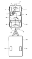
- FIG. 1 is a schematic configuration diagram of a steering control system.
- the vehicle 10 in FIG. 1 is a towing vehicle (tractor) for towing a trailer 50 (towing vehicle).
- the vehicle 10 is a four-wheeled vehicle including a pair of left and right front wheels 11, 11 and a pair of left and right rear wheels 12, 12.
- the vehicle 10 includes a front wheel steering device 14 that controls a steering angle of the front wheels 11 and 11 by an input of a steering wheel (steering wheel) 13 operated by a driver, and a rear wheel 12 according to a command from a steering control device 30 (a steering control unit). , 12 is provided with a rear wheel steering device 16 having a steering actuator for operating the steering angle.
- the steering control device 30 is an electronic control device including a microcomputer having an MPU (Microprocessor Unit), a ROM (Read Only Memory), a RAM (Random Access Memory), and the like.
- the vehicle 10 includes a first external recognition sensor 17 that recognizes a traveling lane or an obstacle in front of the vehicle 10, and a second external recognition sensor 18 that recognizes an obstacle or a trailer 50 behind the vehicle 10.
- the first external recognition sensor 17 and the second external recognition sensor 18 include, for example, a monocular camera and an image processing unit that processes an image of the monocular camera. Acquire recognition information such as objects and trailer movements.
- first external world recognition sensor 17 and the second external world recognition sensor 18 can also obtain recognition information such as a traveling lane, an obstacle, and a trailer motion by a shape recognition device such as a stereo camera or a laser radar.
- the vehicle 10 and the trailer 50 are connected by, for example, a hitch portion 19 (connector) including a hitch ball and a hitch coupler.
- a rolling motion (or a pendulum motion) may occur during traveling due to an influence of an excessive speed, an irregular road surface, a cross wind, and the like. Then, when a rolling motion occurs in the connected vehicle, the trailer 50 vibrates around its vertical axis and vibrates the vehicle 10 via the hitch portion 19, thereby impairing the stability of the connected vehicle. For this reason, the steering control device 30 controls the rear wheel steering angle of the vehicle 10 so as to generate a periodic yaw moment having an opposite phase to the roll motion generated in the coupled vehicle including the vehicle 10 and the trailer 50.
- the trailer stabilization control is performed, and the trailer stabilization control suppresses the roll and stabilizes the connected vehicle.
- FIG. 2 is a configuration block diagram of the steering control device 30.
- the steering control device 30 includes accelerator opening information AO from an accelerator pedal 21 operated by the driver 20, brake opening information BO from a brake pedal 22 operated by the driver 20, and steering wheel 13 operated by the driver 20.
- Driver operation information including angle information is input.
- the steering control device 30 inputs, from the external recognition sensors 17 and 18, information about a traveling lane and an obstacle in front of and behind the vehicle, and information about movement of the trailer 50 behind the vehicle. Further, the steering control device 30 inputs information on the vehicle speed V, which is the vehicle speed of the vehicle 10 from the vehicle speed sensor 23, and information on the longitudinal acceleration and the lateral acceleration from the longitudinal G / lateral G sensor 24.
- the steering control device 30 has functions as an information processing unit 31, a trailer state estimating unit 32, a trailer motion control unit 33, and an actuator control unit 34 for inputting the above various information.
- the information processing unit 31 calculates the motion state of the connected vehicle based on the driver operation information, the outside world recognition information, and the information of the motion state, and further, the vehicle specification information of the vehicle 10 and the trailer 50 stored in the memory.
- the trailer state estimation unit 32 estimates the movement state of the trailer 50 based on the movement state of the connected vehicle calculated by the information processing unit 31.
- the trailer movement control unit 33 generates a control input for stabilizing the movement state of the trailer 50 estimated by the trailer state estimation unit 32.
- the actuator control unit 34 controls the rear wheel steering angle by outputting a steering angle command to the steering actuator of the rear wheel steering device 16 in order to realize the control input generated by the trailer motion control unit 33.
- FIG. 3 is a diagram for explaining the movement of the connected vehicle including the vehicle (tractor) 10 and the trailer 50.
- the yaw rotation Y1 around the center of gravity 10A of the vehicle 10 is mainly caused by the force Ff transmitted from the road surface to the front wheels 11, 11 of the vehicle 10, and the road surface 12 to the rear wheels 12, 12 of the vehicle 10.
- the yaw rotation Y2 about the center of gravity 50A of the trailer 50 is applied to the hitch portion 19 from the trailer 50 side and transmitted to the vehicle 10 and the force Fl transmitted from the road surface to the pair of left and right running wheels 51 and 51 of the trailer 50.
- the magnitudes of the forces Ff and Fr in the vehicle 10 are determined by the motion state of the vehicle 10 such as the front wheel steering angle ⁇ f, the rear wheel steering angle ⁇ r, the side slip angle, and the speed.
- the steering control device 30 outputs the forces Ff and Fr. Is calculated based on the motion state of the vehicle 10, the yaw rate of the vehicle alone can be estimated. Then, the steering control device 30 can estimate the force Fh (external trailer force) by comparing the estimated yaw rate in the case of the vehicle 10 alone with the yaw rate actually generated in the vehicle 10 in the connected vehicle.
- the steering control device 30 determines the motion state of the trailer 50 such as the sideslip angle and speed. From these, the force Fl transmitted from the road surface to the traveling wheels 51, 51 of the trailer 50 can be estimated. As described above, the steering control device 30 estimates the force Fh (external force of the trailer) applied to the hitch portion 19 and the force Fl transmitted from the road surface to the traveling wheels 51, 51 of the trailer 50, thereby obtaining the state of the trailer 50 such as the yaw rate. Can be estimated.
- Fh external force of the trailer
- the steering control device 30 controls the rear wheel steering angle of the vehicle 10 based on the estimation result of the trailer state, thereby manipulating the force Fr transmitted from the road surface to the rear wheels 12, 12 of the vehicle 10, and generating the force on the trailer 50.
- the roll of the connected vehicle is suppressed.
- the control of the rear wheel steering angle by the steering control device 30 is performed in a cycle in which the phase is opposite to the roll motion. Command to generate a typical yaw moment.
- the steering control device 30 can directly obtain the force Fl transmitted from the road surface to the traveling wheels 51, 51 of the trailer 50 from the sensor output.
- FIG. 4 is a control block diagram of the steering control device 30.
- the steering control device 30 first calculates driver operation information 301 such as accelerator opening information AO, brake opening information BO, and steering wheel angle information, and information of a rear wheel steering angle 302 based on vehicle specifications.
- driver operation information 301 such as accelerator opening information AO, brake opening information BO, and steering wheel angle information
- information of a rear wheel steering angle 302 based on vehicle specifications.
- the theoretical vehicle response 304 for the vehicle 10 alone is calculated by inputting it to the vehicle model 303.
- the steering control device 30 responds to the actual vehicle response based on the vehicle motion information (information on the motion status of the vehicle 10) from the on-vehicle sensors 305 (vehicle motion status acquisition unit) such as the vehicle speed sensor 23 and the front / rear G / left / right G sensor 24. 306 is requested. Then, the steering control device 30 estimates the trailer external force 307 applied to the vehicle 10 (the force Fh applied to the hitch 19 from the trailer 50 side and transmitted to the vehicle 10) based on the difference between the theoretical vehicle response 304 and the actual vehicle response 306. .
- vehicle motion information information on the motion status of the vehicle 10
- the on-vehicle sensors 305 vehicle motion status acquisition unit
- the steering control device 306 estimates the trailer external force 307 applied to the vehicle 10 (the force Fh applied to the hitch 19 from the trailer 50 side and transmitted to the vehicle 10) based on the difference between the theoretical vehicle response 304 and the actual vehicle response 306. .
- the steering control device 30 estimates a trailer state 308 such as a force applied to the trailer 50 and a yaw moment based on the trailer external force 307 and the motion of the trailer 50 recognized by the external recognition sensor 18. Then, the steering control device 30 calculates a yaw moment for suppressing the yaw motion of the trailer 50 by the trailer motion control 309, and calculates the yaw moment for suppressing the yaw motion of the trailer 50 by changing the rear wheel steering angle 302. To be generated.
- a trailer state 308 such as a force applied to the trailer 50 and a yaw moment based on the trailer external force 307 and the motion of the trailer 50 recognized by the external recognition sensor 18. Then, the steering control device 30 calculates a yaw moment for suppressing the yaw motion of the trailer 50 by the trailer motion control 309, and calculates the yaw moment for suppressing the yaw motion of the trailer 50 by changing the rear wheel steering angle 302. To be generated.
- the steering control device 30 suppresses the yaw moment of the trailer 50. Is generated by rear wheel steering, and the yaw motion of the trailer 50 is reduced.
- the steering control device 30 can measure the trailer motion by using a yaw rate sensor, an acceleration sensor, a sensor that measures the angle of the hitch 19, or the like mounted on the trailer 50.
- FIG. 5 shows a three-wheel vehicle model.
- x, y, and z are coordinate axes of the coordinate system of the vehicle 10.
- the positive direction of the coordinate axis x is the forward direction of the vehicle 10
- the positive direction of the coordinate axis y is the left direction of the vehicle 10
- the positive direction of the coordinate axis z is the upward direction of the vehicle 10.
- xt, yt, and zt are coordinate axes of the coordinate system of the trailer 50.
- the positive direction of the coordinate axis xt is the forward direction of the trailer 50
- the positive direction of the coordinate axis yt is the leftward direction of the trailer 50
- the positive direction of the coordinate axis zt is the upward direction of the trailer 50.
- Lf is the distance between the front wheels 11, 11 and the vehicle center of gravity 10A
- Lr is the distance between the rear wheels 12, 12 and the vehicle center of gravity 10A
- Lh is the distance between the hitch 19 and the vehicle center of gravity 10A
- Lth is the distance between the hitch 19 and the vehicle.
- the distance between the trailer center of gravity 50A and Ltr is the distance between the running wheels 51 and 51 of the trailer 50 and the trailer center of gravity 50A.
- mv is the mass of the vehicle 10
- Jvzz is the yaw moment of inertia of the vehicle 10
- ⁇ is the yaw angle of the vehicle 10 (dot is the yaw angular velocity)
- mt is the mass of the trailer 50
- Jtzz is the yaw moment of inertia of the trailer 50
- ⁇ t is The yaw angle of the trailer 50 (dot is the yaw angular velocity).
- ⁇ f is the steering angle of the front wheels 11 of the vehicle 10
- ⁇ r is the steering angle of the rear wheels 12 of the vehicle 10.
- fxf is the vertical tire force of the front wheels 11, 11 of the vehicle 10
- the forward direction is the forward direction of the vehicle 10.
- fyf is defined by the tire force in the lateral direction of the front wheels 11, 11 of the vehicle 10 and the forward direction is defined as the left direction of the vehicle 10.
- fxr is the forward direction of the vehicle 10 in the forward direction due to the tire force in the vertical direction of the rear wheels 12, 12 of the vehicle 10.
- fyr is defined by the tire force in the lateral direction of the rear wheels 12 and 12 of the vehicle 10 and the forward direction is set to the left direction of the vehicle 10.
- fxh is a vertical hitch force and the forward direction is a forward direction
- fyh is a horizontal hitch force and a forward direction is a left direction
- Fxt is a vertical tire of the running wheels 51 and 51 of the trailer 50.
- the forward direction is the forward direction of the trailer 50 by force
- fyt is the leftward direction of the trailer 50 by the tire force in the lateral direction of the running wheels 51, 51 of the trailer 50.
- ⁇ is a hitch angle.
- Equation 1 The equation of motion of the vehicle 10 is as shown in Equation 1.
- Equation 3 the equation of motion is defined as in Equation 3. Note that each variable in Equation 3 is as shown in Equation 4.
- the steering control device 30 can estimate the motion of the trailer 50 according to Expression 6 by using the estimation result by the observer (state estimator) in Expression 5. Then, the steering control device 30 performs trailer stabilization control (rear wheel steering control) based on the estimated motion of the trailer 50.
- trailer stabilization control rear wheel steering control
- FIG. 6 is a flowchart showing the procedure of the trailer stabilization control.
- the steering control device 30 obtains driver operation information such as the front wheel steering angle ⁇ f.
- the steering control device 30 acquires vehicle motion information (vehicle sensor information) such as the yaw rate and the vehicle speed of the vehicle 10 detected by the vehicle-mounted sensor.
- vehicle motion information vehicle sensor information
- step S503 the steering control device 30 calculates a theoretical vehicle response based on the driver's operation information acquired in step S501, and calculates an actual vehicle response based on the vehicle motion information (in-vehicle sensor information) acquired in step S502. Then, a difference between the theoretical vehicle response and the actual vehicle response is determined. Then, in step S504, the steering control device 30 determines a trailer external force (the force Fh applied to the hitch portion 19 from the trailer 50 side and transmitted to the vehicle 10) based on the difference between the theoretical vehicle response and the actual vehicle response.
- a trailer external force the force Fh applied to the hitch portion 19 from the trailer 50 side and transmitted to the vehicle
- the steering control device 30 acquires information on the relative position of the trailer 50 with respect to the vehicle 10 by the external recognition sensor 18 in step S505. Then, in step S506, the steering control device 30 estimates a trailer state such as the yaw rate of the trailer 50 based on the trailer external force obtained in step S504 and the relative position between the vehicle 10 and the trailer 50.
- step S507 the steering control device 30 obtains a difference between the yaw rate of the vehicle 10 and the yaw rate of the trailer 50, and determines whether or not the absolute value of the difference exceeds a threshold.
- the steering control device 30 if the absolute value of the difference between the yaw rate of the vehicle 10 and the yaw rate of the trailer 50 does not exceed the threshold, the steering control device 30 returns to step S501 and does not execute the trailer stabilization control.
- step S508 a hitch force (trailer motion compensation hitch force) for suppressing the yaw motion of the trailer 50 is obtained.
- step S509 the steering control device 30 proceeds to step S509, and obtains a target rear wheel steering angle ⁇ r for generating the hitch force obtained in step S508.
- the steering control device 30 proceeds to step S510, and controls the rear wheel steering device 16 (steering actuator) based on the target rear wheel steering angle ⁇ r obtained in step S509.
- the steering control device 30 controls the motion of the trailer 50 such that the difference between the yaw rate of the vehicle 10 and the yaw rate of the trailer 50 is reduced by the rear wheel steering control.
- FIG. 7 is a time chart illustrating changes in the yaw rate and the rear wheel steering angle when the steering control device 30 performs the trailer stabilization control.
- the theoretical vehicle yaw rate (theoretical vehicle response) of the vehicle 10 alone calculated by the steering control device 30 based on the vehicle speed and vehicle specifications becomes the front wheel steering angle ⁇ f.
- the response changes in accordance with the change in.
- the actual yaw rate of the vehicle 10 shows a different behavior from the theoretical vehicle yaw rate when the vehicle 10 receives an external force from the trailer 50 (trailer external force).
- the actual yaw rate of the vehicle 10 also changes periodically because the trailer external force changes periodically.
- the estimated value of the yaw rate of the trailer 50 obtained by the steering control device 30 indicates a variation according to the trailer external force.
- the steering control device 30 calculates a difference between the theoretical vehicle yaw rate and the estimated trailer yaw rate, and when the difference exceeds a threshold value, generates a periodic yaw moment having an opposite phase to the roll motion in rear wheel steering. Outputs the angle command.
- the yaw rate of the trailer 50 is stabilized.
- the steering angle of the rear wheels 12, 12 is controlled, so that a change in the speed of the vehicle 10 due to the trailer stabilization control can be suppressed. Further, since the yaw moment that can be generated by controlling the rear wheel steering angle is larger than the yaw moment that can be generated by the automatic brake, a larger trailer 50 can be generated than when the yaw moment is generated by the automatic brake. It is possible to stabilize the running of the vehicle 10 to which the vehicle is connected.
- the trailer stabilization control system can suppress the yaw motion of the trailer 50 by the rear wheel steering control and the automatic brake control by the steering control device 30.
- the trailer stabilization control system When the yaw moment that can be generated by the rear wheel steering control by the steering control device 30 is insufficient to suppress the yaw motion of the trailer 50, the trailer stabilization control system generates the yaw moment generated by the automatic brake. Can be added.
- the present invention is not limited to the above-described embodiment, and includes various modifications.
- the above-described embodiments have been described in detail for easy understanding of the present invention, and are not necessarily limited to those having all the configurations described above.
- a part of the configuration of one embodiment can be replaced with the configuration of another embodiment, and the configuration of one embodiment can be added to the configuration of another embodiment.
Abstract
The steering control device, steering control method, and steering control system according to the present invention involve outputting a command to generate periodic yawing moments, which are in antiphase with a side-to-side rolling motion generated in combination vehicles including a vehicle and a trailer, to a rear-wheel steering device that controls the steering angle of the rear wheels of the vehicle.
Description
本発明は、トレーラを牽引する車両の操舵を制御する、操舵制御装置、操舵制御方法、及び操舵制御システムに関する。
The present invention relates to a steering control device, a steering control method, and a steering control system that control the steering of a vehicle towing a trailer.
特許文献1は、自動車及びトレーラからなる連結車において横揺れ運動が発生したときに、横揺れ運動に対して逆位相となる周期的なヨーモーメントを自動ブレーキ作動によって発生させる、車両の安定化方法を開示する。
Patent Literature 1 discloses a vehicle stabilization method in which when a rolling motion occurs in a connected vehicle including an automobile and a trailer, a periodic yaw moment having a phase opposite to that of the rolling motion is generated by an automatic braking operation. Is disclosed.
しかし、車両の自動ブレーキで発生させることができるヨーモーメントは、大型のトレーラに対しては十分ではなく、横揺れ運動を効果的に抑制することができない可能性があった。
また、横揺れ運動を抑制するためのブレーキ作動によって、車両の速度が変化してしまうという課題があった。 However, the yaw moment that can be generated by the automatic braking of the vehicle is not sufficient for a large trailer, and it may not be possible to effectively suppress the rolling motion.
Further, there is a problem that the speed of the vehicle changes due to a brake operation for suppressing the rolling motion.
本発明の目的は、車両の速度変化を抑止しつつ、より大きなトレーラを連結した場合においても横揺れ運動を抑制することができる、操舵制御装置、操舵制御方法、及び操舵制御システムを提供することにある。
An object of the present invention is to provide a steering control device, a steering control method, and a steering control system capable of suppressing a roll motion even when a larger trailer is connected, while suppressing a change in vehicle speed. It is in.
本発明の一実施形態によれば、その1つの態様において、車両及びトレーラを含む連結車に発生する横揺れ運動に対して逆位相となる周期的なヨーモーメントを発生させる指令を、車両の後輪の操舵角を制御する後輪操舵装置に出力する。
According to one embodiment of the present invention, in one aspect, a command to generate a periodic yaw moment that is in phase opposition to the roll motion generated in a coupled vehicle including a vehicle and a trailer is issued to the rear of the vehicle. Output to the rear wheel steering device that controls the steering angle of the wheels.
本発明の一実施形態によれば、車両の速度変化を抑止しつつ、大型のトレーラが連結した場合においても横揺れ運動を抑制することができる。
According to one embodiment of the present invention, it is possible to suppress the rolling motion even when a large trailer is connected, while suppressing a change in the speed of the vehicle.
以下、本発明に係る操舵制御装置、操舵制御方法、及び操舵制御システムの実施形態を、図面に基づいて説明する。
図1は、操舵制御システムの概略構成図である。
図1の車両10は、トレーラ50(被牽引車)を牽引する牽引車(トラクタ)である。
車両10は、左右一対の前輪11,11、及び、左右一対の後輪12,12を備えた4輪車両である。 Hereinafter, embodiments of a steering control device, a steering control method, and a steering control system according to the present invention will be described with reference to the drawings.
FIG. 1 is a schematic configuration diagram of a steering control system.
Thevehicle 10 in FIG. 1 is a towing vehicle (tractor) for towing a trailer 50 (towing vehicle).
Thevehicle 10 is a four-wheeled vehicle including a pair of left and right front wheels 11, 11 and a pair of left and right rear wheels 12, 12.
図1は、操舵制御システムの概略構成図である。
図1の車両10は、トレーラ50(被牽引車)を牽引する牽引車(トラクタ)である。
車両10は、左右一対の前輪11,11、及び、左右一対の後輪12,12を備えた4輪車両である。 Hereinafter, embodiments of a steering control device, a steering control method, and a steering control system according to the present invention will be described with reference to the drawings.
FIG. 1 is a schematic configuration diagram of a steering control system.
The
The
車両10は、運転者が操作する操舵輪(ステアリングホイール)13の入力によって前輪11,11の操舵角を操作する前輪操舵装置14、操舵制御装置30(操舵制御部)からの指令によって後輪12,12の操舵角を操作する操舵アクチュエータを有した後輪操舵装置16を備える。
なお、操舵制御装置30は、MPU(Microprocessor Unit)、ROM(Read Only Memory)、RAM(Random Access Memory)などを有するマイクロコンピュータを備えた電子制御装置である。 Thevehicle 10 includes a front wheel steering device 14 that controls a steering angle of the front wheels 11 and 11 by an input of a steering wheel (steering wheel) 13 operated by a driver, and a rear wheel 12 according to a command from a steering control device 30 (a steering control unit). , 12 is provided with a rear wheel steering device 16 having a steering actuator for operating the steering angle.
Thesteering control device 30 is an electronic control device including a microcomputer having an MPU (Microprocessor Unit), a ROM (Read Only Memory), a RAM (Random Access Memory), and the like.
なお、操舵制御装置30は、MPU(Microprocessor Unit)、ROM(Read Only Memory)、RAM(Random Access Memory)などを有するマイクロコンピュータを備えた電子制御装置である。 The
The
また、車両10は、車両10の前方の走行車線や障害物を認識する第1外界認識センサ17、及び、車両10の後方の障害物やトレーラ50を認識する第2外界認識センサ18を備える。
なお、第1外界認識センサ17,第2外界認識センサ18(外界認識部)は、例えば単眼カメラと当該単眼カメラの画像を処理する画像処理部とを有し、画像処理によって、走行車線、障害物、トレーラ運動などの認識情報を取得する。 Further, thevehicle 10 includes a first external recognition sensor 17 that recognizes a traveling lane or an obstacle in front of the vehicle 10, and a second external recognition sensor 18 that recognizes an obstacle or a trailer 50 behind the vehicle 10.
The firstexternal recognition sensor 17 and the second external recognition sensor 18 (external recognition unit) include, for example, a monocular camera and an image processing unit that processes an image of the monocular camera. Acquire recognition information such as objects and trailer movements.
なお、第1外界認識センサ17,第2外界認識センサ18(外界認識部)は、例えば単眼カメラと当該単眼カメラの画像を処理する画像処理部とを有し、画像処理によって、走行車線、障害物、トレーラ運動などの認識情報を取得する。 Further, the
The first
また、第1外界認識センサ17,第2外界認識センサ18は、ステレオカメラやレーザレーダなどの形状認識装置によって、走行車線、障害物、トレーラ運動などの認識情報を取得することもできる。
車両10とトレーラ50とは、例えばヒッチボールとヒッチカプラとからなるヒッチ部19(連結器)によって連結する。 Further, the first externalworld recognition sensor 17 and the second external world recognition sensor 18 can also obtain recognition information such as a traveling lane, an obstacle, and a trailer motion by a shape recognition device such as a stereo camera or a laser radar.
Thevehicle 10 and the trailer 50 are connected by, for example, a hitch portion 19 (connector) including a hitch ball and a hitch coupler.
車両10とトレーラ50とは、例えばヒッチボールとヒッチカプラとからなるヒッチ部19(連結器)によって連結する。 Further, the first external
The
上記の車両10及びトレーラ50からなる連結車においては、過度な速度、不整な路面、横風などの影響によって、走行中に横揺れ運動(乃至振り子運動)が発生することがある。
そして、連結車に横揺れ運動が発生すると、トレーラ50は、その垂直軸周りに振動しかつヒッチ部19を介して車両10を振動させ、連結車の安定性を損なうことになる。
このため、操舵制御装置30は、車両10及びトレーラ50を含む連結車に発生する横揺れ運動に対して逆位相となる周期的なヨーモーメントを発生させるように車両10の後輪操舵角を制御するトレーラ安定化制御を実施し、係るトレーラ安定化制御によって横揺れを抑止して連結車を安定化させる。 In the connected vehicle including thevehicle 10 and the trailer 50, a rolling motion (or a pendulum motion) may occur during traveling due to an influence of an excessive speed, an irregular road surface, a cross wind, and the like.
Then, when a rolling motion occurs in the connected vehicle, thetrailer 50 vibrates around its vertical axis and vibrates the vehicle 10 via the hitch portion 19, thereby impairing the stability of the connected vehicle.
For this reason, thesteering control device 30 controls the rear wheel steering angle of the vehicle 10 so as to generate a periodic yaw moment having an opposite phase to the roll motion generated in the coupled vehicle including the vehicle 10 and the trailer 50. The trailer stabilization control is performed, and the trailer stabilization control suppresses the roll and stabilizes the connected vehicle.
そして、連結車に横揺れ運動が発生すると、トレーラ50は、その垂直軸周りに振動しかつヒッチ部19を介して車両10を振動させ、連結車の安定性を損なうことになる。
このため、操舵制御装置30は、車両10及びトレーラ50を含む連結車に発生する横揺れ運動に対して逆位相となる周期的なヨーモーメントを発生させるように車両10の後輪操舵角を制御するトレーラ安定化制御を実施し、係るトレーラ安定化制御によって横揺れを抑止して連結車を安定化させる。 In the connected vehicle including the
Then, when a rolling motion occurs in the connected vehicle, the
For this reason, the
図2は、操舵制御装置30の構成ブロック図である。
操舵制御装置30は、運転者20が操作するアクセルペダル21からのアクセル開度情報AO、運転者20が操作するブレーキペダル22からのブレーキ開度情報BO、運転者20が操作する操舵輪13の角度情報などを含む運転者操作情報を入力する。 FIG. 2 is a configuration block diagram of thesteering control device 30.
Thesteering control device 30 includes accelerator opening information AO from an accelerator pedal 21 operated by the driver 20, brake opening information BO from a brake pedal 22 operated by the driver 20, and steering wheel 13 operated by the driver 20. Driver operation information including angle information is input.
操舵制御装置30は、運転者20が操作するアクセルペダル21からのアクセル開度情報AO、運転者20が操作するブレーキペダル22からのブレーキ開度情報BO、運転者20が操作する操舵輪13の角度情報などを含む運転者操作情報を入力する。 FIG. 2 is a configuration block diagram of the
The
また、操舵制御装置30は、外界認識センサ17,18から、車両前方及び車両後方における走行車線、障害物に関する情報、更に、車両後方のトレーラ50の運動に関する情報を入力する。
更に、操舵制御装置30は、車速センサ23からの車両10の車体速度である車速Vに関する情報、前後G/左右Gセンサ24からの前後加速度及び左右加速度に関する情報を入力する。 In addition, thesteering control device 30 inputs, from the external recognition sensors 17 and 18, information about a traveling lane and an obstacle in front of and behind the vehicle, and information about movement of the trailer 50 behind the vehicle.
Further, thesteering control device 30 inputs information on the vehicle speed V, which is the vehicle speed of the vehicle 10 from the vehicle speed sensor 23, and information on the longitudinal acceleration and the lateral acceleration from the longitudinal G / lateral G sensor 24.
更に、操舵制御装置30は、車速センサ23からの車両10の車体速度である車速Vに関する情報、前後G/左右Gセンサ24からの前後加速度及び左右加速度に関する情報を入力する。 In addition, the
Further, the
操舵制御装置30は、上記の各種情報を入力する情報処理部31、トレーラ状態推定部32、トレーラ運動制御部33、アクチュエータ制御部34としての機能を有する。
情報処理部31は、運転者操作情報、外界認識情報及び運動状態の情報、更に、メモリに記憶してある車両10及びトレーラ50の車両諸元情報に基づき、連結車の運動状態を算出する。 Thesteering control device 30 has functions as an information processing unit 31, a trailer state estimating unit 32, a trailer motion control unit 33, and an actuator control unit 34 for inputting the above various information.
Theinformation processing unit 31 calculates the motion state of the connected vehicle based on the driver operation information, the outside world recognition information, and the information of the motion state, and further, the vehicle specification information of the vehicle 10 and the trailer 50 stored in the memory.
情報処理部31は、運転者操作情報、外界認識情報及び運動状態の情報、更に、メモリに記憶してある車両10及びトレーラ50の車両諸元情報に基づき、連結車の運動状態を算出する。 The
The
トレーラ状態推定部32は、情報処理部31で算出した連結車の運動状態に基づき、トレーラ50の運動状態を推定する。
トレーラ運動制御部33は、トレーラ状態推定部32が推定したトレーラ50の運動状態を安定化させるための制御入力を生成する。
アクチュエータ制御部34は、トレーラ運動制御部33が生成した制御入力を実現するため、後輪操舵装置16の操舵アクチュエータに舵角指令を出力して後輪操舵角を制御する。 The trailerstate estimation unit 32 estimates the movement state of the trailer 50 based on the movement state of the connected vehicle calculated by the information processing unit 31.
The trailermovement control unit 33 generates a control input for stabilizing the movement state of the trailer 50 estimated by the trailer state estimation unit 32.
Theactuator control unit 34 controls the rear wheel steering angle by outputting a steering angle command to the steering actuator of the rear wheel steering device 16 in order to realize the control input generated by the trailer motion control unit 33.
トレーラ運動制御部33は、トレーラ状態推定部32が推定したトレーラ50の運動状態を安定化させるための制御入力を生成する。
アクチュエータ制御部34は、トレーラ運動制御部33が生成した制御入力を実現するため、後輪操舵装置16の操舵アクチュエータに舵角指令を出力して後輪操舵角を制御する。 The trailer
The trailer
The
図3は、車両(トラクタ)10及びトレーラ50からなる連結車の運動を説明するための図である。
車両10及びトレーラ50からなる連結車において、車両10の重心10A回りのヨー回転運動Y1は、主に車両10の前輪11,11に路面から伝わる力Ff、車両10の後輪12,12に路面から伝わる力Fr、及び、ヒッチ部19にトレーラ50側から加わり車両10に伝わる力Fhによって発生する。 FIG. 3 is a diagram for explaining the movement of the connected vehicle including the vehicle (tractor) 10 and thetrailer 50.
In the connected vehicle including thevehicle 10 and the trailer 50, the yaw rotation Y1 around the center of gravity 10A of the vehicle 10 is mainly caused by the force Ff transmitted from the road surface to the front wheels 11, 11 of the vehicle 10, and the road surface 12 to the rear wheels 12, 12 of the vehicle 10. And the force Fh applied to the hitch portion 19 from the trailer 50 side and transmitted to the vehicle 10.
車両10及びトレーラ50からなる連結車において、車両10の重心10A回りのヨー回転運動Y1は、主に車両10の前輪11,11に路面から伝わる力Ff、車両10の後輪12,12に路面から伝わる力Fr、及び、ヒッチ部19にトレーラ50側から加わり車両10に伝わる力Fhによって発生する。 FIG. 3 is a diagram for explaining the movement of the connected vehicle including the vehicle (tractor) 10 and the
In the connected vehicle including the
一方、トレーラ50の重心50A回りのヨー回転運動Y2は、ヒッチ部19にトレーラ50側から加わり車両10に伝わる力Fh、及び、トレーラ50の左右一対の走行輪51,51に路面から伝わる力Flによって発生する。
そして、車両10における力Ff及び力Frは、前輪操舵角δf、後輪操舵角δr、横滑り角、速度などの車両10の運動状態によってその大きさが決まる。 On the other hand, the yaw rotation Y2 about the center ofgravity 50A of the trailer 50 is applied to the hitch portion 19 from the trailer 50 side and transmitted to the vehicle 10 and the force Fl transmitted from the road surface to the pair of left and right running wheels 51 and 51 of the trailer 50. Caused by
The magnitudes of the forces Ff and Fr in thevehicle 10 are determined by the motion state of the vehicle 10 such as the front wheel steering angle δf, the rear wheel steering angle δr, the side slip angle, and the speed.
そして、車両10における力Ff及び力Frは、前輪操舵角δf、後輪操舵角δr、横滑り角、速度などの車両10の運動状態によってその大きさが決まる。 On the other hand, the yaw rotation Y2 about the center of
The magnitudes of the forces Ff and Fr in the
ここで、連結車ではなく車両10単体とした場合、車両10のヨー慣性モーメントに基づき、力Ff及び力Frによって車両10で発生するヨーレートが決まるから、操舵制御装置30は、力Ff及び力Frを車両10の運動状態に基づき求めれば、車両単体でのヨーレートを推定できる。
そして、操舵制御装置30は、車両10単体の場合での推定ヨーレートと、連結車で車両10に実際に発生しているヨーレートとを比較することで、力Fh(トレーラ外力)を推定できる。 Here, when thevehicle 10 is a single vehicle instead of a connected vehicle, the yaw rate generated in the vehicle 10 is determined by the forces Ff and Fr based on the yaw moment of inertia of the vehicle 10, and therefore, the steering control device 30 outputs the forces Ff and Fr. Is calculated based on the motion state of the vehicle 10, the yaw rate of the vehicle alone can be estimated.
Then, thesteering control device 30 can estimate the force Fh (external trailer force) by comparing the estimated yaw rate in the case of the vehicle 10 alone with the yaw rate actually generated in the vehicle 10 in the connected vehicle.
そして、操舵制御装置30は、車両10単体の場合での推定ヨーレートと、連結車で車両10に実際に発生しているヨーレートとを比較することで、力Fh(トレーラ外力)を推定できる。 Here, when the
Then, the
一方、トレーラ50の車両諸元が既知である場合、トレーラ50のヨー運動(ヨーイング)を外界認識センサ18などが計測すれば、操舵制御装置30は、トレーラ50の横滑り角や速度などの運動状態を求めることができ、これらからトレーラ50の走行輪51,51に路面から伝わる力Flを推定できる。
以上のように、操舵制御装置30は、ヒッチ部19に加わる力Fh(トレーラ外力)及びトレーラ50の走行輪51,51に路面から伝わる力Flを推定することで、トレーラ50のヨーレートなどの状態を推定できる。 On the other hand, when the vehicle specifications of thetrailer 50 are known, if the yaw motion (yawing) of the trailer 50 is measured by the external recognition sensor 18 or the like, the steering control device 30 determines the motion state of the trailer 50 such as the sideslip angle and speed. From these, the force Fl transmitted from the road surface to the traveling wheels 51, 51 of the trailer 50 can be estimated.
As described above, thesteering control device 30 estimates the force Fh (external force of the trailer) applied to the hitch portion 19 and the force Fl transmitted from the road surface to the traveling wheels 51, 51 of the trailer 50, thereby obtaining the state of the trailer 50 such as the yaw rate. Can be estimated.
以上のように、操舵制御装置30は、ヒッチ部19に加わる力Fh(トレーラ外力)及びトレーラ50の走行輪51,51に路面から伝わる力Flを推定することで、トレーラ50のヨーレートなどの状態を推定できる。 On the other hand, when the vehicle specifications of the
As described above, the
そして、操舵制御装置30は、トレーラ状態の推定結果に基づき車両10の後輪操舵角を制御することで、車両10の後輪12,12に路面から伝わる力Frを操作し、トレーラ50に発生しているヨー運動を抑制する方向の力をヒッチ部19の力で発生させることで、連結車の横揺れを抑制する。
ここで、連結車の横揺れによって車両10及びトレーラ50に発生するヨーレートは周期的に変動するから、操舵制御装置30による後輪操舵角の制御は、横揺れ運動に対して逆位相となる周期的なヨーモーメントを発生させる指令になる。
なお、トレーラ50にヨーレートセンサや加速度センサを搭載することで、操舵制御装置30は、トレーラ50の走行輪51,51に路面から伝わる力Flを、センサ出力から直接求めることができる。 Then, thesteering control device 30 controls the rear wheel steering angle of the vehicle 10 based on the estimation result of the trailer state, thereby manipulating the force Fr transmitted from the road surface to the rear wheels 12, 12 of the vehicle 10, and generating the force on the trailer 50. By generating a force in the direction of suppressing the yawing motion by the force of the hitch portion 19, the roll of the connected vehicle is suppressed.
Here, since the yaw rate generated in thevehicle 10 and the trailer 50 due to the roll of the connected vehicle periodically fluctuates, the control of the rear wheel steering angle by the steering control device 30 is performed in a cycle in which the phase is opposite to the roll motion. Command to generate a typical yaw moment.
By mounting a yaw rate sensor or an acceleration sensor on thetrailer 50, the steering control device 30 can directly obtain the force Fl transmitted from the road surface to the traveling wheels 51, 51 of the trailer 50 from the sensor output.
ここで、連結車の横揺れによって車両10及びトレーラ50に発生するヨーレートは周期的に変動するから、操舵制御装置30による後輪操舵角の制御は、横揺れ運動に対して逆位相となる周期的なヨーモーメントを発生させる指令になる。
なお、トレーラ50にヨーレートセンサや加速度センサを搭載することで、操舵制御装置30は、トレーラ50の走行輪51,51に路面から伝わる力Flを、センサ出力から直接求めることができる。 Then, the
Here, since the yaw rate generated in the
By mounting a yaw rate sensor or an acceleration sensor on the
図4は、操舵制御装置30の制御ブロック線図である。
操舵制御装置30は、まず、アクセル開度情報AO、ブレーキ開度情報BO、及び操舵輪角度情報などの運転者の操作情報301や、後輪操舵角302の情報を、車両諸元に基づいた車両モデル303へ入力し、車両10単体時の理論車両応答304を算出する。 FIG. 4 is a control block diagram of thesteering control device 30.
Thesteering control device 30 first calculates driver operation information 301 such as accelerator opening information AO, brake opening information BO, and steering wheel angle information, and information of a rear wheel steering angle 302 based on vehicle specifications. The theoretical vehicle response 304 for the vehicle 10 alone is calculated by inputting it to the vehicle model 303.
操舵制御装置30は、まず、アクセル開度情報AO、ブレーキ開度情報BO、及び操舵輪角度情報などの運転者の操作情報301や、後輪操舵角302の情報を、車両諸元に基づいた車両モデル303へ入力し、車両10単体時の理論車両応答304を算出する。 FIG. 4 is a control block diagram of the
The
また、操舵制御装置30は、車速センサ23や前後G/左右Gセンサ24などの車載センサ305(車両運動状態取得部)からの車両運動情報(車両10の運動状態に関する情報)に基づき実車両応答306を求める。
そして、操舵制御装置30は、理論車両応答304と実車両応答306との差分に基づき、車両10に加わるトレーラ外力307(ヒッチ部19にトレーラ50側から加わり車両10に伝わる力Fh)を推定する。 Further, thesteering control device 30 responds to the actual vehicle response based on the vehicle motion information (information on the motion status of the vehicle 10) from the on-vehicle sensors 305 (vehicle motion status acquisition unit) such as the vehicle speed sensor 23 and the front / rear G / left / right G sensor 24. 306 is requested.
Then, thesteering control device 30 estimates the trailer external force 307 applied to the vehicle 10 (the force Fh applied to the hitch 19 from the trailer 50 side and transmitted to the vehicle 10) based on the difference between the theoretical vehicle response 304 and the actual vehicle response 306. .
そして、操舵制御装置30は、理論車両応答304と実車両応答306との差分に基づき、車両10に加わるトレーラ外力307(ヒッチ部19にトレーラ50側から加わり車両10に伝わる力Fh)を推定する。 Further, the
Then, the
更に、操舵制御装置30は、トレーラ外力307と、外界認識センサ18によって認識したトレーラ50の運動に基づき、トレーラ50に加わっている力やヨーモーメントなどのトレーラ状態308を推定する。
そして、操舵制御装置30は、トレーラ50のヨー運動を抑制するヨーモーメントをトレーラ運動制御309によって算出し、トレーラ50のヨー運動を抑制するヨーモーメントを、後輪操舵角302を変化させることで実際に発生させる。 Further, thesteering control device 30 estimates a trailer state 308 such as a force applied to the trailer 50 and a yaw moment based on the trailer external force 307 and the motion of the trailer 50 recognized by the external recognition sensor 18.
Then, thesteering control device 30 calculates a yaw moment for suppressing the yaw motion of the trailer 50 by the trailer motion control 309, and calculates the yaw moment for suppressing the yaw motion of the trailer 50 by changing the rear wheel steering angle 302. To be generated.
そして、操舵制御装置30は、トレーラ50のヨー運動を抑制するヨーモーメントをトレーラ運動制御309によって算出し、トレーラ50のヨー運動を抑制するヨーモーメントを、後輪操舵角302を変化させることで実際に発生させる。 Further, the
Then, the
ここで、操舵制御装置30は、閾値を超えるヨー運動がトレーラ50で発生する場合、換言すれば、トレーラ50のヨー運動が許容レベルを超えるときに、係るトレーラ50のヨー運動を抑制するヨーモーメントを後輪操舵によって発生させ、トレーラ50のヨー運動を低下させる。
なお、操舵制御装置30は、トレーラ50に搭載したヨーレートセンサや加速度センサ、ヒッチ部19の角度を計測するセンサなどを用いて、トレーラ運動の計測を行うことができる。 Here, when the yaw motion exceeding the threshold occurs in thetrailer 50, in other words, when the yaw motion of the trailer 50 exceeds the allowable level, the steering control device 30 suppresses the yaw moment of the trailer 50. Is generated by rear wheel steering, and the yaw motion of the trailer 50 is reduced.
Thesteering control device 30 can measure the trailer motion by using a yaw rate sensor, an acceleration sensor, a sensor that measures the angle of the hitch 19, or the like mounted on the trailer 50.
なお、操舵制御装置30は、トレーラ50に搭載したヨーレートセンサや加速度センサ、ヒッチ部19の角度を計測するセンサなどを用いて、トレーラ運動の計測を行うことができる。 Here, when the yaw motion exceeding the threshold occurs in the
The
図5は、3輪車両モデルを示している。
図5において、x、y、zは車両10の座標系の座標軸である。この座標系において、座標軸xの正方向は車両10の前方向で、座標軸yの正方向は車両10の左方向で、座標軸zの正方向は車両10の上方向である。
また、xt、yt、ztは、トレーラ50の座標系の座標軸である。この座標系において、座標軸xtの正方向はトレーラ50の前方向で、座標軸ytの正方向はトレーラ50の左方向で、座標軸ztの正方向はトレーラ50の上方向である。 FIG. 5 shows a three-wheel vehicle model.
In FIG. 5, x, y, and z are coordinate axes of the coordinate system of thevehicle 10. In this coordinate system, the positive direction of the coordinate axis x is the forward direction of the vehicle 10, the positive direction of the coordinate axis y is the left direction of the vehicle 10, and the positive direction of the coordinate axis z is the upward direction of the vehicle 10.
Further, xt, yt, and zt are coordinate axes of the coordinate system of thetrailer 50. In this coordinate system, the positive direction of the coordinate axis xt is the forward direction of the trailer 50, the positive direction of the coordinate axis yt is the leftward direction of the trailer 50, and the positive direction of the coordinate axis zt is the upward direction of the trailer 50.
図5において、x、y、zは車両10の座標系の座標軸である。この座標系において、座標軸xの正方向は車両10の前方向で、座標軸yの正方向は車両10の左方向で、座標軸zの正方向は車両10の上方向である。
また、xt、yt、ztは、トレーラ50の座標系の座標軸である。この座標系において、座標軸xtの正方向はトレーラ50の前方向で、座標軸ytの正方向はトレーラ50の左方向で、座標軸ztの正方向はトレーラ50の上方向である。 FIG. 5 shows a three-wheel vehicle model.
In FIG. 5, x, y, and z are coordinate axes of the coordinate system of the
Further, xt, yt, and zt are coordinate axes of the coordinate system of the
また、Lfは前輪11,11と車両重心10A間の距離、Lrは後輪12,12と車両重心10A間の距離、Lhはヒッチ部19と車両重心10A間の距離、Lthはヒッチ部19とトレーラ重心50A間の距離、Ltrはトレーラ50の走行輪51,51とトレーラ重心50A間の距離である。
また、mvは車両10の質量、Jvzzは車両10のヨー慣性モーメント、ψは車両10のヨー角(ドットはヨー角速度)、mtはトレーラ50の質量、Jtzzはトレーラ50のヨー慣性モーメント、ψtはトレーラ50のヨー角(ドットはヨー角速度)である。 Lf is the distance between the front wheels 11, 11 and the vehicle center of gravity 10A, Lr is the distance between the rear wheels 12, 12 and the vehicle center of gravity 10A, Lh is the distance between the hitch 19 and the vehicle center of gravity 10A, and Lth is the distance between the hitch 19 and the vehicle. The distance between the trailer center of gravity 50A and Ltr is the distance between the running wheels 51 and 51 of the trailer 50 and the trailer center of gravity 50A.
Further, mv is the mass of thevehicle 10, Jvzz is the yaw moment of inertia of the vehicle 10, ψ is the yaw angle of the vehicle 10 (dot is the yaw angular velocity), mt is the mass of the trailer 50, Jtzz is the yaw moment of inertia of the trailer 50, and Δt is The yaw angle of the trailer 50 (dot is the yaw angular velocity).
また、mvは車両10の質量、Jvzzは車両10のヨー慣性モーメント、ψは車両10のヨー角(ドットはヨー角速度)、mtはトレーラ50の質量、Jtzzはトレーラ50のヨー慣性モーメント、ψtはトレーラ50のヨー角(ドットはヨー角速度)である。 Lf is the distance between the
Further, mv is the mass of the
また、δfは車両10の前輪11,11の操舵角、δrは車両10の後輪12,12の操舵角である。
また、fxfは車両10の前輪11,11の縦方向のタイヤ力で正方向を車両10の前方向とする。fyfは車両10の前輪11,11の横方向のタイヤ力で正方向を車両10の左方向とする。fxrは車両10の後輪12,12の縦方向のタイヤ力で正方向を車両10の前方向とする。fyrは車両10の後輪12,12の横方向のタイヤ力で正方向を車両10の左方向とする。 Δf is the steering angle of thefront wheels 11 of the vehicle 10, and δr is the steering angle of the rear wheels 12 of the vehicle 10.
Further, fxf is the vertical tire force of the front wheels 11, 11 of the vehicle 10, and the forward direction is the forward direction of the vehicle 10. fyf is defined by the tire force in the lateral direction of the front wheels 11, 11 of the vehicle 10 and the forward direction is defined as the left direction of the vehicle 10. fxr is the forward direction of the vehicle 10 in the forward direction due to the tire force in the vertical direction of the rear wheels 12, 12 of the vehicle 10. fyr is defined by the tire force in the lateral direction of the rear wheels 12 and 12 of the vehicle 10 and the forward direction is set to the left direction of the vehicle 10.
また、fxfは車両10の前輪11,11の縦方向のタイヤ力で正方向を車両10の前方向とする。fyfは車両10の前輪11,11の横方向のタイヤ力で正方向を車両10の左方向とする。fxrは車両10の後輪12,12の縦方向のタイヤ力で正方向を車両10の前方向とする。fyrは車両10の後輪12,12の横方向のタイヤ力で正方向を車両10の左方向とする。 Δf is the steering angle of the
Further, fxf is the vertical tire force of the
また、fxhは縦方向のヒッチ力で正方向を前方向とし、fyhは横方向のヒッチ力で正方向を左方向とする. また、fxtはトレーラ50の走行輪51,51の縦方向のタイヤ力で正方向をトレーラ50の前方向とし、fytはトレーラ50の走行輪51,51の横方向のタイヤ力で正方向をトレーラ50の左方向とする。
また、εはヒッチ角である。 In addition, fxh is a vertical hitch force and the forward direction is a forward direction, and fyh is a horizontal hitch force and a forward direction is a left direction. Fxt is a vertical tire of the running wheels 51 and 51 of the trailer 50. The forward direction is the forward direction of the trailer 50 by force, and fyt is the leftward direction of the trailer 50 by the tire force in the lateral direction of the running wheels 51, 51 of the trailer 50.
Ε is a hitch angle.
また、εはヒッチ角である。 In addition, fxh is a vertical hitch force and the forward direction is a forward direction, and fyh is a horizontal hitch force and a forward direction is a left direction. Fxt is a vertical tire of the running
Ε is a hitch angle.
そして、車両10の運動方程式は、数式1のようになる。

The equation of motion of the vehicle 10 is as shown in Equation 1.
同様にトレーラ50の運動方程式は、数式2のようになる。

Similarly, the equation of motion of the trailer 50 is as shown in Expression 2.
ここで、運動方程式を数式3のように定義する。

なお、数式3の各変数は数式4に示す通りである。

Here, the equation of motion is defined as in Equation 3.
Note that each variable in Equation 3 is as shown in Equation 4.
操舵制御装置30は、数式5のオブザーバ(状態推定器)による推定結果を用いることで、数式6にしたがって、トレーラ50の運動を推定できる。


そして、操舵制御装置30は、推定したトレーラ50の運動に基づき、トレーラ安定化制御(後輪操舵制御)を行う。
The steering control device 30 can estimate the motion of the trailer 50 according to Expression 6 by using the estimation result by the observer (state estimator) in Expression 5.
Then, the steering control device 30 performs trailer stabilization control (rear wheel steering control) based on the estimated motion of the trailer 50.
図6は、上記トレーラ安定化制御の手順を示すフローチャートである。
操舵制御装置30は、まず、ステップS501で、前輪操舵角δfなどの運転者の操作情報を取得する。
また、操舵制御装置30は、ステップS502で、車載センサが検出した車両10のヨーレート、車速などの車両運動情報(車載センサ情報)を取得する。 FIG. 6 is a flowchart showing the procedure of the trailer stabilization control.
First, in step S501, thesteering control device 30 obtains driver operation information such as the front wheel steering angle δf.
In step S502, thesteering control device 30 acquires vehicle motion information (vehicle sensor information) such as the yaw rate and the vehicle speed of the vehicle 10 detected by the vehicle-mounted sensor.
操舵制御装置30は、まず、ステップS501で、前輪操舵角δfなどの運転者の操作情報を取得する。
また、操舵制御装置30は、ステップS502で、車載センサが検出した車両10のヨーレート、車速などの車両運動情報(車載センサ情報)を取得する。 FIG. 6 is a flowchart showing the procedure of the trailer stabilization control.
First, in step S501, the
In step S502, the
次いで、操舵制御装置30は、ステップS503で、ステップS501で取得した運転者の操作情報に基づき理論車両応答を求めるとともに、ステップS502で取得した車両運動情報(車載センサ情報)に基づき実車両応答を求め、更に、理論車両応答と実車両応答との差分を求める。
そして、操舵制御装置30は、ステップS504で、理論車両応答と実車両応答との差分に基づき、トレーラ外力(ヒッチ部19にトレーラ50側から加わり車両10に伝わる力Fh)を求める。 Next, in step S503, thesteering control device 30 calculates a theoretical vehicle response based on the driver's operation information acquired in step S501, and calculates an actual vehicle response based on the vehicle motion information (in-vehicle sensor information) acquired in step S502. Then, a difference between the theoretical vehicle response and the actual vehicle response is determined.
Then, in step S504, thesteering control device 30 determines a trailer external force (the force Fh applied to the hitch portion 19 from the trailer 50 side and transmitted to the vehicle 10) based on the difference between the theoretical vehicle response and the actual vehicle response.
そして、操舵制御装置30は、ステップS504で、理論車両応答と実車両応答との差分に基づき、トレーラ外力(ヒッチ部19にトレーラ50側から加わり車両10に伝わる力Fh)を求める。 Next, in step S503, the
Then, in step S504, the
また、操舵制御装置30は、ステップS505で、外界認識センサ18によって、車両10に対するトレーラ50の相対位置の情報を取得する。
そして、操舵制御装置30は、ステップS506で、ステップS504で求めたトレーラ外力、車両10とトレーラ50との相対位置に基づき、トレーラ50のヨーレートなどのトレーラ状態を推定する。 In addition, thesteering control device 30 acquires information on the relative position of the trailer 50 with respect to the vehicle 10 by the external recognition sensor 18 in step S505.
Then, in step S506, thesteering control device 30 estimates a trailer state such as the yaw rate of the trailer 50 based on the trailer external force obtained in step S504 and the relative position between the vehicle 10 and the trailer 50.
そして、操舵制御装置30は、ステップS506で、ステップS504で求めたトレーラ外力、車両10とトレーラ50との相対位置に基づき、トレーラ50のヨーレートなどのトレーラ状態を推定する。 In addition, the
Then, in step S506, the
次に、操舵制御装置30は、ステップS507で、車両10のヨーレートとトレーラ50のヨーレートの差分を求め、差分の絶対値が閾値を超えているか否かを判断する。
ここで、車両10のヨーレートとトレーラ50のヨーレートとの差分の絶対値が閾値を超えていない場合、操舵制御装置30は、ステップS501に戻り、トレーラ安定化制御を実施しない。 Next, in step S507, thesteering control device 30 obtains a difference between the yaw rate of the vehicle 10 and the yaw rate of the trailer 50, and determines whether or not the absolute value of the difference exceeds a threshold.
Here, if the absolute value of the difference between the yaw rate of thevehicle 10 and the yaw rate of the trailer 50 does not exceed the threshold, the steering control device 30 returns to step S501 and does not execute the trailer stabilization control.
ここで、車両10のヨーレートとトレーラ50のヨーレートとの差分の絶対値が閾値を超えていない場合、操舵制御装置30は、ステップS501に戻り、トレーラ安定化制御を実施しない。 Next, in step S507, the
Here, if the absolute value of the difference between the yaw rate of the
一方、車両10のヨーレートとトレーラ50のヨーレートとの差分の絶対値が閾値を超えていて、連結車の安定性を向上させるためにトレーラ50のヨー運動を抑制する必要がある場合、操舵制御装置30は、ステップS508で、トレーラ50のヨー運動を抑制するためのヒッチ力(トレーラ運動補償ヒッチ力)を求める。
次いで、操舵制御装置30は、ステップS509に進み、ステップS508で求めたヒッチ力を発生させるための目標後輪操舵角δrを求める。 On the other hand, when the absolute value of the difference between the yaw rate of thevehicle 10 and the yaw rate of the trailer 50 exceeds the threshold value and it is necessary to suppress the yaw movement of the trailer 50 to improve the stability of the connected vehicle, the steering control device In step S508, a hitch force (trailer motion compensation hitch force) for suppressing the yaw motion of the trailer 50 is obtained.
Next, thesteering control device 30 proceeds to step S509, and obtains a target rear wheel steering angle δr for generating the hitch force obtained in step S508.
次いで、操舵制御装置30は、ステップS509に進み、ステップS508で求めたヒッチ力を発生させるための目標後輪操舵角δrを求める。 On the other hand, when the absolute value of the difference between the yaw rate of the
Next, the
そして、操舵制御装置30は、ステップS510に進み、ステップS509で求めた目標後輪操舵角δrに基づき後輪操舵装置16(操舵アクチュエータ)を制御する。
操舵制御装置30は、係る後輪操舵制御によって、車両10のヨーレートとトレーラ50のヨーレートとの差が小さくなるようにトレーラ50の運動を制御する。 Then, thesteering control device 30 proceeds to step S510, and controls the rear wheel steering device 16 (steering actuator) based on the target rear wheel steering angle δr obtained in step S509.
Thesteering control device 30 controls the motion of the trailer 50 such that the difference between the yaw rate of the vehicle 10 and the yaw rate of the trailer 50 is reduced by the rear wheel steering control.
操舵制御装置30は、係る後輪操舵制御によって、車両10のヨーレートとトレーラ50のヨーレートとの差が小さくなるようにトレーラ50の運動を制御する。 Then, the
The
図7は、操舵制御装置30がトレーラ安定化制御を実施するときのヨーレートや後輪操舵角の変化を例示するタイムチャートである。
車両10の運転者が操舵を行って前輪操舵角δfが変化すると、操舵制御装置30が車速や車両諸元に基づき算出する車両10単体での理論車両ヨーレート(理論車両応答)が前輪操舵角δfの変化に応じて応答変化する。 FIG. 7 is a time chart illustrating changes in the yaw rate and the rear wheel steering angle when thesteering control device 30 performs the trailer stabilization control.
When the driver of thevehicle 10 steers and the front wheel steering angle δf changes, the theoretical vehicle yaw rate (theoretical vehicle response) of the vehicle 10 alone calculated by the steering control device 30 based on the vehicle speed and vehicle specifications becomes the front wheel steering angle δf. The response changes in accordance with the change in.
車両10の運転者が操舵を行って前輪操舵角δfが変化すると、操舵制御装置30が車速や車両諸元に基づき算出する車両10単体での理論車両ヨーレート(理論車両応答)が前輪操舵角δfの変化に応じて応答変化する。 FIG. 7 is a time chart illustrating changes in the yaw rate and the rear wheel steering angle when the
When the driver of the
ここで、車両10にトレーラ50を連結している場合、車両10の実際のヨーレートは、車両10がトレーラ50からの外力(トレーラ外力)を受けることで、理論車両ヨーレートとは異なる挙動を示し、トレーラ50が横揺れ運動すると、トレーラ外力が周期的に変動することで、車両10の実際のヨーレートも周期的に変動する。
このとき、操舵制御装置30が求めるトレーラ50のヨーレートの推定値は、トレーラ外力に応じた変動を示す。 Here, when thetrailer 50 is connected to the vehicle 10, the actual yaw rate of the vehicle 10 shows a different behavior from the theoretical vehicle yaw rate when the vehicle 10 receives an external force from the trailer 50 (trailer external force). When the trailer 50 rolls sideways, the actual yaw rate of the vehicle 10 also changes periodically because the trailer external force changes periodically.
At this time, the estimated value of the yaw rate of thetrailer 50 obtained by the steering control device 30 indicates a variation according to the trailer external force.
このとき、操舵制御装置30が求めるトレーラ50のヨーレートの推定値は、トレーラ外力に応じた変動を示す。 Here, when the
At this time, the estimated value of the yaw rate of the
ここで、操舵制御装置30は、理論車両ヨーレートと推定トレーラヨーレートの差分を求め、差分が閾値を超えるときに、横揺れ運動に対して逆位相となる周期的なヨーモーメントを発生させる後輪操舵角の指令を出力する。
係る後輪操舵制御によって、トレーラ50のヨーレートが安定化する。 Here, thesteering control device 30 calculates a difference between the theoretical vehicle yaw rate and the estimated trailer yaw rate, and when the difference exceeds a threshold value, generates a periodic yaw moment having an opposite phase to the roll motion in rear wheel steering. Outputs the angle command.
By such rear wheel steering control, the yaw rate of thetrailer 50 is stabilized.
係る後輪操舵制御によって、トレーラ50のヨーレートが安定化する。 Here, the
By such rear wheel steering control, the yaw rate of the
操舵制御装置30によるトレーラ安定化制御では、後輪12,12の操舵角を制御するから、トレーラ安定化制御に伴って車両10の速度が変化することを抑制できる。
また、後輪操舵角の制御によって発生させることができるヨーモーメントは、自動ブレーキによって発生させることができるヨーモーメントよりも大きいから、自動ブレーキでヨーモーメントを発生させる場合よりも、より大型のトレーラ50を連結した車両10で走行を安定化させることが可能となる。 In the trailer stabilization control by thesteering control device 30, the steering angle of the rear wheels 12, 12 is controlled, so that a change in the speed of the vehicle 10 due to the trailer stabilization control can be suppressed.
Further, since the yaw moment that can be generated by controlling the rear wheel steering angle is larger than the yaw moment that can be generated by the automatic brake, alarger trailer 50 can be generated than when the yaw moment is generated by the automatic brake. It is possible to stabilize the running of the vehicle 10 to which the vehicle is connected.
また、後輪操舵角の制御によって発生させることができるヨーモーメントは、自動ブレーキによって発生させることができるヨーモーメントよりも大きいから、自動ブレーキでヨーモーメントを発生させる場合よりも、より大型のトレーラ50を連結した車両10で走行を安定化させることが可能となる。 In the trailer stabilization control by the
Further, since the yaw moment that can be generated by controlling the rear wheel steering angle is larger than the yaw moment that can be generated by the automatic brake, a
上記実施形態で説明した各態様は、矛盾が生じない限りにおいて、適宜組み合わせて使用することができる。
また、好ましい実施形態を参照して本発明の内容を具体的に説明したが、本発明の基本的技術思想及び教示に基づいて、当業者であれば、種々の変形態様を採り得ることは自明である。 The aspects described in the above embodiments can be used in appropriate combinations as long as no contradiction occurs.
Although the content of the present invention has been specifically described with reference to the preferred embodiments, it is obvious that those skilled in the art can adopt various modifications based on the basic technical idea and teaching of the present invention. It is.
トレーラ安定化制御システムは、操舵制御装置30による後輪操舵制御及び自動ブレーキ制御によって、トレーラ50のヨー運動を抑制することができる。そして、トレーラ安定化制御システムは、操舵制御装置30による後輪操舵制御で発生させることができるヨーモーメントではトレーラ50のヨー運動の抑制に不十分であるときに、自動ブレーキによって発生させるヨーモーメントを付加することできる。
The trailer stabilization control system can suppress the yaw motion of the trailer 50 by the rear wheel steering control and the automatic brake control by the steering control device 30. When the yaw moment that can be generated by the rear wheel steering control by the steering control device 30 is insufficient to suppress the yaw motion of the trailer 50, the trailer stabilization control system generates the yaw moment generated by the automatic brake. Can be added.
なお、本発明は上記した実施形態に限定されるものではなく、様々な変形例が含まれる。例えば、上記した実施形態は本発明を分かりやすく説明するために詳細に説明したものであり、必ずしも説明した全ての構成を備えるものに限定されるものではない。また、ある実施形態の構成の一部を他の実施形態の構成に置き換えることが可能であり、また、ある実施形態の構成に他の実施形態の構成を加えることも可能である。また、各実施形態の構成の一部について、他の構成の追加・削除・置換をすることが可能である。
Note that the present invention is not limited to the above-described embodiment, and includes various modifications. For example, the above-described embodiments have been described in detail for easy understanding of the present invention, and are not necessarily limited to those having all the configurations described above. In addition, a part of the configuration of one embodiment can be replaced with the configuration of another embodiment, and the configuration of one embodiment can be added to the configuration of another embodiment. Further, for a part of the configuration of each embodiment, it is possible to add, delete, or replace another configuration.
本願は、2018年9月3日付出願の日本国特許出願第2018-164588号に基づく優先権を主張する。2018年9月3日付出願の日本国特許出願第2018-164588号の明細書、特許請求の範囲、図面、および要約書を含む全開示内容は、参照により本願に全体として組み込まれる。
This application claims the priority based on Japanese Patent Application No. 2018-164588 filed on Sep. 3, 2018. The entire disclosure of Japanese Patent Application No. 2018-164588 filed on Sep. 3, 2018, including the specification, claims, drawings, and abstract, is incorporated herein by reference in its entirety.
10…車両、11,11…前輪、12,12…後輪、14…前輪操舵装置、16…後輪操舵装置、18…外界認識センサ、19…ヒッチ部、30…操舵制御装置
# 10: vehicle, 11, 11, front wheel, 12, 12, rear wheel, 14: front wheel steering device, 16: rear wheel steering device, 18: external field recognition sensor, 19: hitch unit, 30: steering control device
Claims (10)
- トレーラを牽引する車両の操舵制御装置であって、前記操舵制御装置は、
前記車両および前記トレーラを含む連結車に発生する横揺れ運動に関する情報を取得し、
取得した前記横揺れ運動に関する情報に基づき、前記横揺れ運動に対して逆位相となる周期的なヨーモーメントを発生させる指令を、前記車両の後輪の操舵角を制御する後輪操舵装置に出力する、
操舵制御装置。 A steering control device for a vehicle towing a trailer, wherein the steering control device includes:
Acquiring information on the rolling motion that occurs in the connected vehicle including the vehicle and the trailer,
Based on the acquired information about the rolling motion, a command to generate a periodic yaw moment having an opposite phase to the rolling motion is output to a rear wheel steering device that controls a steering angle of a rear wheel of the vehicle. Do
Steering control device. - 請求項1に記載の操舵制御装置において、
前記横揺れ運動に関する情報は前記トレーラのヨー運動に関する情報であり、
前記操舵制御装置は、前記トレーラのヨー運動に対して逆位相となる周期的なヨーモーメントを発生させる指令を、前記車両の後輪の操舵角を制御する後輪操舵装置に出力する、
操舵制御装置。 The steering control device according to claim 1,
The information about the roll motion is information about the yaw motion of the trailer,
The steering control device outputs a command to generate a periodic yaw moment having an opposite phase to the yaw motion of the trailer to a rear wheel steering device that controls a steering angle of a rear wheel of the vehicle.
Steering control device. - 請求項2に記載の操舵制御装置において、
前記操舵制御装置は、前記車両と前記トレーラとを連結するヒッチ部に加わる前記トレーラの外力と、外界認識部で取得された前記車両の外界に関する情報と、に基づき前記トレーラのヨー運動を求める、
操舵制御装置。 The steering control device according to claim 2,
The steering control device obtains a yaw motion of the trailer based on an external force of the trailer applied to a hitch unit connecting the vehicle and the trailer, and information on the external world of the vehicle acquired by an external world recognition unit.
Steering control device. - 請求項3に記載の操舵制御装置において、
前記操舵制御装置は、前記車両単体でのヨーレートと、前記連結車のヨーレートと、に基づき前記トレーラの外力を求める、
操舵制御装置。 The steering control device according to claim 3,
The steering control device obtains an external force of the trailer based on the yaw rate of the vehicle alone and the yaw rate of the connected vehicle,
Steering control device. - 請求項2に記載の操舵制御装置において、
前記操舵制御装置は、前記トレーラのヨー運動に対して逆位相となる周期的なヨーモーメントを、前記車両と前記トレーラとを連結するヒッチ部の力で発生させる、
操舵制御装置。 The steering control device according to claim 2,
The steering control device generates a periodic yaw moment having an opposite phase to the yaw motion of the trailer by a force of a hitch portion connecting the vehicle and the trailer,
Steering control device. - トレーラを牽引する車両の操舵制御装置であって、前記操舵制御装置は、
前記トレーラのヨー運動に関する情報に基づき、前記車両の後輪操舵装置に後輪の操舵角を制御する指令を出力する、
操舵制御装置。 A steering control device for a vehicle towing a trailer, wherein the steering control device includes:
Based on information on the yaw motion of the trailer, output a command to control a steering angle of a rear wheel to a rear wheel steering device of the vehicle,
Steering control device. - トレーラを牽引する車両の操舵制御方法であって、前記操舵制御方法は、
前記車両および前記トレーラを含む連結車に発生する横揺れ運動に関する情報を取得し、
取得した前記横揺れ運動に関する情報に基づき、前記横揺れ運動に対して逆位相となる周期的なヨーモーメントを発生させる指令を、前記車両の後輪の操舵角を制御する後輪操舵装置に出力する、
操舵制御方法。 A steering control method for a vehicle towing a trailer, wherein the steering control method includes:
Acquiring information on the rolling motion that occurs in the connected vehicle including the vehicle and the trailer,
Based on the acquired information about the rolling motion, a command to generate a periodic yaw moment having an opposite phase to the rolling motion is output to a rear wheel steering device that controls a steering angle of a rear wheel of the vehicle. Do
Steering control method. - 請求項7に記載の操舵制御方法において、
前記横揺れ運動に関する情報は前記トレーラのヨー運動に関する情報であり、
前記トレーラのヨー運動に対して逆位相となる周期的なヨーモーメントを発生させる指令を、前記車両の後輪の操舵角を制御する後輪操舵装置に出力する、
操舵制御方法。 The steering control method according to claim 7,
The information about the roll motion is information about the yaw motion of the trailer,
A command to generate a periodic yaw moment having an opposite phase to the yaw motion of the trailer is output to a rear wheel steering device that controls a steering angle of a rear wheel of the vehicle.
Steering control method. - トレーラを牽引する車両の操舵制御システムであって、前記操舵制御システムは、
前記車両の運動状態に関する情報を取得する車両運動状態取得部と、
前記車両の外界に関する情報を取得する外界認識部と、
前記車両運動状態取得部によって取得された前記車両の運動状態に関する情報と、前記外界認識部によって取得された前記車両の外界に関する情報と、に基づき求められた前記車両および前記トレーラを含む連結車に発生する横揺れ運動に関する情報を取得し、取得した前記横揺れ運動に関する情報に基づき、前記横揺れ運動に対して逆位相となる周期的なヨーモーメントを発生させる指令を出力する操舵制御部と、
前記操舵制御部より出力された前記指令を取得し、前記車両の後輪の操舵角を制御する後輪操舵装置と、
を備える操舵制御システム。 A steering control system for a vehicle towing a trailer, wherein the steering control system includes:
A vehicle motion state acquisition unit that acquires information on the motion state of the vehicle,
An external world recognition unit that acquires information about the external world of the vehicle,
Information on the motion state of the vehicle acquired by the vehicle motion state acquisition unit, and information on the outside world of the vehicle acquired by the outside world recognition unit, and the connected vehicle including the vehicle and the trailer obtained based on the A steering control unit that acquires information about the rolling motion to be generated, and outputs a command to generate a periodic yaw moment having an opposite phase to the rolling motion based on the acquired information about the rolling motion,
A rear wheel steering device that acquires the command output from the steering control unit and controls a steering angle of a rear wheel of the vehicle;
A steering control system comprising: - 請求項9に記載の操舵制御システムにおいて、
前記操舵制御部は、前記横揺れ運動に関する情報として前記トレーラのヨー運動に関する情報を取得し、前記トレーラのヨー運動に対して逆位相となる周期的なヨーモーメントを発生させる指令を、前記車両の後輪の操舵角を制御する後輪操舵装置に出力する、
操舵制御システム。 The steering control system according to claim 9,
The steering control unit obtains information about the yaw motion of the trailer as the information about the roll motion, and issues a command to generate a periodic yaw moment having an opposite phase to the yaw motion of the trailer. Output to a rear wheel steering device that controls the steering angle of the rear wheels,
Steering control system.
Priority Applications (3)
| Application Number | Priority Date | Filing Date | Title |
|---|---|---|---|
| DE112019004416.8T DE112019004416T5 (en) | 2018-09-03 | 2019-08-02 | STEERING CONTROL DEVICE, STEERING CONTROL METHOD AND STEERING CONTROL SYSTEM |
| CN201980054630.8A CN112770959B (en) | 2018-09-03 | 2019-08-02 | Steering control device, steering control method, and steering control system |
| US17/272,833 US20210347409A1 (en) | 2018-09-03 | 2019-08-02 | Steering Control Apparatus, Steering Control Method, and Steering Control System |
Applications Claiming Priority (2)
| Application Number | Priority Date | Filing Date | Title |
|---|---|---|---|
| JP2018164588A JP7152906B2 (en) | 2018-09-03 | 2018-09-03 | Steering control device, steering control method, and steering control system |
| JP2018-164588 | 2018-09-03 |
Publications (1)
| Publication Number | Publication Date |
|---|---|
| WO2020049919A1 true WO2020049919A1 (en) | 2020-03-12 |
Family
ID=69722805
Family Applications (1)
| Application Number | Title | Priority Date | Filing Date |
|---|---|---|---|
| PCT/JP2019/030448 WO2020049919A1 (en) | 2018-09-03 | 2019-08-02 | Steering control device, steering control method, and steering control system |
Country Status (5)
| Country | Link |
|---|---|
| US (1) | US20210347409A1 (en) |
| JP (1) | JP7152906B2 (en) |
| CN (1) | CN112770959B (en) |
| DE (1) | DE112019004416T5 (en) |
| WO (1) | WO2020049919A1 (en) |
Cited By (1)
| Publication number | Priority date | Publication date | Assignee | Title |
|---|---|---|---|---|
| WO2022111801A1 (en) * | 2020-11-25 | 2022-06-02 | Volvo Truck Corporation | A method of controlling a vehicle combination |
Families Citing this family (3)
| Publication number | Priority date | Publication date | Assignee | Title |
|---|---|---|---|---|
| JP7405660B2 (en) * | 2020-03-19 | 2023-12-26 | Lineヤフー株式会社 | Output device, output method and output program |
| KR20210158453A (en) * | 2020-06-23 | 2021-12-31 | 현대자동차주식회사 | Appratus and method for controlling articulation of articulated vehicle |
| US11814098B2 (en) * | 2021-03-11 | 2023-11-14 | GM Global Technology Operations LLC | Methods, systems, and apparatuses for identification and compensation of trailer impacts on steering dynamics for automated driving |
Citations (6)
| Publication number | Priority date | Publication date | Assignee | Title |
|---|---|---|---|---|
| JPH0467183U (en) * | 1990-10-17 | 1992-06-15 | ||
| JPH08150951A (en) * | 1994-11-30 | 1996-06-11 | Mitsubishi Motors Corp | Steering control method and device for rear wheel of tractor in combination of vehicle |
| JPH09267762A (en) * | 1996-04-01 | 1997-10-14 | Mitsubishi Motors Corp | Trailer wheel steering control method and its device |
| JP2003503276A (en) * | 1999-06-30 | 2003-01-28 | ロベルト・ボッシュ・ゲゼルシャフト・ミト・ベシュレンクテル・ハフツング | Method and apparatus for stabilizing an automobile |
| JP2009012488A (en) * | 2007-06-29 | 2009-01-22 | Honda Motor Co Ltd | Movement stabilizing apparatus for combination vehicle |
| WO2010087022A1 (en) * | 2009-02-02 | 2010-08-05 | トヨタ自動車株式会社 | Behavior controller of combination vehicle |
Family Cites Families (9)
| Publication number | Priority date | Publication date | Assignee | Title |
|---|---|---|---|---|
| DE19964048A1 (en) * | 1999-06-30 | 2001-01-04 | Bosch Gmbh Robert | Method and device for stabilizing a road vehicle |
| US7640089B2 (en) * | 2005-04-06 | 2009-12-29 | Gm Global Technology Operations, Inc. | Vehicle-trailer stability and handling performance improvement using rear-wheel steering control |
| US8380390B2 (en) * | 2009-06-24 | 2013-02-19 | Robert Bosch Gmbh | Method and system of determining load characteristics of a trailer |
| CN102753408B (en) * | 2010-02-02 | 2016-02-10 | 丰田自动车株式会社 | The Behavior-Based control device of vehicle |
| US8700282B2 (en) * | 2011-07-28 | 2014-04-15 | Advics Co., Ltd. | Method and apparatus for vehicle sway detection and reduction |
| JP6069148B2 (en) * | 2013-09-19 | 2017-02-01 | 日立オートモティブシステムズ株式会社 | Vehicle control device |
| US20160318493A1 (en) * | 2014-03-10 | 2016-11-03 | Dean Drako | Anti-jackknifing apparatus for articulated vehicles |
| CN105292251A (en) * | 2015-11-11 | 2016-02-03 | 吉林大学 | Four-wheel steering system for automobile |
| US9873426B2 (en) * | 2016-06-21 | 2018-01-23 | Ford Global Technologies, Llc | System for mitigating vehicle sway |
-
2018
- 2018-09-03 JP JP2018164588A patent/JP7152906B2/en active Active
-
2019
- 2019-08-02 WO PCT/JP2019/030448 patent/WO2020049919A1/en active Application Filing
- 2019-08-02 US US17/272,833 patent/US20210347409A1/en active Pending
- 2019-08-02 CN CN201980054630.8A patent/CN112770959B/en active Active
- 2019-08-02 DE DE112019004416.8T patent/DE112019004416T5/en active Pending
Patent Citations (6)
| Publication number | Priority date | Publication date | Assignee | Title |
|---|---|---|---|---|
| JPH0467183U (en) * | 1990-10-17 | 1992-06-15 | ||
| JPH08150951A (en) * | 1994-11-30 | 1996-06-11 | Mitsubishi Motors Corp | Steering control method and device for rear wheel of tractor in combination of vehicle |
| JPH09267762A (en) * | 1996-04-01 | 1997-10-14 | Mitsubishi Motors Corp | Trailer wheel steering control method and its device |
| JP2003503276A (en) * | 1999-06-30 | 2003-01-28 | ロベルト・ボッシュ・ゲゼルシャフト・ミト・ベシュレンクテル・ハフツング | Method and apparatus for stabilizing an automobile |
| JP2009012488A (en) * | 2007-06-29 | 2009-01-22 | Honda Motor Co Ltd | Movement stabilizing apparatus for combination vehicle |
| WO2010087022A1 (en) * | 2009-02-02 | 2010-08-05 | トヨタ自動車株式会社 | Behavior controller of combination vehicle |
Cited By (1)
| Publication number | Priority date | Publication date | Assignee | Title |
|---|---|---|---|---|
| WO2022111801A1 (en) * | 2020-11-25 | 2022-06-02 | Volvo Truck Corporation | A method of controlling a vehicle combination |
Also Published As
| Publication number | Publication date |
|---|---|
| CN112770959A (en) | 2021-05-07 |
| US20210347409A1 (en) | 2021-11-11 |
| JP7152906B2 (en) | 2022-10-13 |
| CN112770959B (en) | 2023-06-02 |
| JP2020037301A (en) | 2020-03-12 |
| DE112019004416T5 (en) | 2021-05-27 |
Similar Documents
| Publication | Publication Date | Title |
|---|---|---|
| WO2020049919A1 (en) | Steering control device, steering control method, and steering control system | |
| EP1941413B1 (en) | Enhanced yaw stability control to mitigate a vehicle's abnormal yaw motion due to a disturbance force applied to vehicle body | |
| EP1574386B1 (en) | Vehicle stability control system | |
| US8010252B2 (en) | Trailer oscillation detection and compensation method for a vehicle and trailer combination | |
| JP4631549B2 (en) | Vehicle motion stabilization control device | |
| US8359155B2 (en) | Vehicle driving operation support apparatus/method and vehicle | |
| JP4997065B2 (en) | Vehicle control device | |
| JP6926210B2 (en) | Reduction of lateral position deviation during lane change | |
| JP4600339B2 (en) | Obstacle avoidance control device and obstacle avoidance control program | |
| JP5227082B2 (en) | Vehicle steering control device equipped with a four-wheel steering mechanism | |
| JP2007022117A (en) | Vehicle stabilization control system | |
| GB2571589A (en) | Terrain inference method and apparatus | |
| WO2019166142A1 (en) | Methods and apparatus for acquisition and tracking, object classification and terrain inference | |
| US11941847B2 (en) | Controller for a vehicle | |
| JP3271956B2 (en) | Road surface friction coefficient estimation device for vehicles | |
| JP4942488B2 (en) | Control method and control system for steering angle of steerable rear wheel, and vehicle having the control system | |
| JP7165204B2 (en) | Steering control device, steering control method, and steering control system |
Legal Events
| Date | Code | Title | Description |
|---|---|---|---|
| 121 | Ep: the epo has been informed by wipo that ep was designated in this application |
Ref document number: 19856897 Country of ref document: EP Kind code of ref document: A1 |
|
| 122 | Ep: pct application non-entry in european phase |
Ref document number: 19856897 Country of ref document: EP Kind code of ref document: A1 |