WO2020045035A1 - 路面状態判定システム、路面状態判定プログラム及び路面状態判定方法 - Google Patents
路面状態判定システム、路面状態判定プログラム及び路面状態判定方法 Download PDFInfo
- Publication number
- WO2020045035A1 WO2020045035A1 PCT/JP2019/031406 JP2019031406W WO2020045035A1 WO 2020045035 A1 WO2020045035 A1 WO 2020045035A1 JP 2019031406 W JP2019031406 W JP 2019031406W WO 2020045035 A1 WO2020045035 A1 WO 2020045035A1
- Authority
- WO
- WIPO (PCT)
- Prior art keywords
- road surface
- surface state
- vehicle
- state
- tire
- Prior art date
- Legal status (The legal status is an assumption and is not a legal conclusion. Google has not performed a legal analysis and makes no representation as to the accuracy of the status listed.)
- Ceased
Links
Images





Classifications
-
- B—PERFORMING OPERATIONS; TRANSPORTING
- B60—VEHICLES IN GENERAL
- B60C—VEHICLE TYRES; TYRE INFLATION; TYRE CHANGING; CONNECTING VALVES TO INFLATABLE ELASTIC BODIES IN GENERAL; DEVICES OR ARRANGEMENTS RELATED TO TYRES
- B60C19/00—Tyre parts or constructions not otherwise provided for
-
- B—PERFORMING OPERATIONS; TRANSPORTING
- B60—VEHICLES IN GENERAL
- B60W—CONJOINT CONTROL OF VEHICLE SUB-UNITS OF DIFFERENT TYPE OR DIFFERENT FUNCTION; CONTROL SYSTEMS SPECIALLY ADAPTED FOR HYBRID VEHICLES; ROAD VEHICLE DRIVE CONTROL SYSTEMS FOR PURPOSES NOT RELATED TO THE CONTROL OF A PARTICULAR SUB-UNIT
- B60W40/00—Estimation or calculation of non-directly measurable driving parameters for road vehicle drive control systems not related to the control of a particular sub unit, e.g. by using mathematical models
- B60W40/02—Estimation or calculation of non-directly measurable driving parameters for road vehicle drive control systems not related to the control of a particular sub unit, e.g. by using mathematical models related to ambient conditions
- B60W40/06—Road conditions
-
- G—PHYSICS
- G01—MEASURING; TESTING
- G01W—METEOROLOGY
- G01W1/00—Meteorology
Definitions
- the present invention relates to a road surface state determination system, a road surface state determination program, and a road surface state determination method for determining a road surface state of a road on which a tire rolls.
- a road surface condition for example, dry, wet (wet), snow (snow), etc.
- a determination system is known (see Patent Document 1).
- Patent Literature 1 the accuracy of road surface state determination is improved by using acceleration data acquired from a plurality of vehicles within a predetermined time and additionally using information such as weather during the predetermined time. Let me.
- the accuracy of determination of the road surface condition can be improved, but there are actually the following problems. Specifically, when the tire to which the acceleration sensor is attached changes over time such as progress of wear or change in internal pressure, the acquired acceleration data may also change.
- the road surface state may be erroneously determined. For example, there may be a case where the road surface state of snow is erroneously determined to be wet.
- An object of the present invention is to provide a road surface state determination method.
- One embodiment of the present invention determines the road surface state of the road on which the tire rolls based on acceleration data obtained by an acceleration sensor (acceleration sensor 111) attached to the inner surface of the tire (pneumatic tire 10).
- a road surface state determination system (road surface state determination system 100) that obtains the road surface state determined based on a predetermined determination algorithm using the acceleration data (road surface state acquisition unit 301)
- vehicle state information indicating the state of the vehicle (vehicle V) on which the tire is mounted, environmental information indicating the surrounding environment of the vehicle, and the acceleration of the tire mounted on another vehicle (peripheral vehicle Vp)
- a supplementary information acquisition unit (vehicle state acquisition unit 303, environment information acquisition unit 305) for acquiring supplementary information including at least one of the road surface states determined using data; With feet information, and a the road surface condition updating unit configured to update the road surface condition obtained by the road surface condition acquisition unit (road surface condition update unit 307).
- One embodiment of the present invention is a road surface condition determination program that determines a road surface condition of a road surface on which the tire rolls, based on acceleration data obtained by an acceleration sensor attached to an inner surface of the tire.
- One aspect of the present invention is a road surface condition determining method for determining a road surface condition of a road surface on which the tire rolls, based on acceleration data obtained by an acceleration sensor attached to an inner surface of the tire, wherein the acceleration Using data, acquiring the road surface state determined based on a predetermined determination algorithm, and vehicle state information indicating an operation state of equipment of a vehicle to which the tire is mounted, indicating a surrounding environment of the vehicle.
- FIG. 1 is a schematic side view of a vehicle V on which a pneumatic tire 10 is mounted.
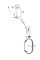
- FIG. 2 is an overall schematic configuration diagram of the road surface state determination system 100.
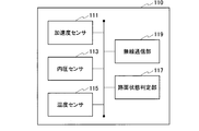
- FIG. 3 is a functional block configuration diagram of the sensor unit 110.
- FIG. 4 is a functional block configuration diagram of the processing device 120.
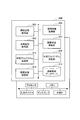
- FIG. 5 is a functional block configuration diagram of the road surface state determination server 300.
- FIG. 6 is a diagram showing an update sequence of a road surface state determination algorithm by the road surface state determination system 100.
- FIG. 7 is a diagram illustrating a flow of the road surface state labeling operation performed by the road surface state determination server 300.
- FIG. 8 is a diagram illustrating a flow of the labeling operation of the road surface state performed by the road surface state determination server 300.
- FIG. 1 is a schematic side view of a vehicle V on which a pneumatic tire 10 is mounted.
- FIG. 2 is an overall schematic configuration diagram of the road surface state determination system 100.
- FIG. 3 is a functional
- FIG. 9 is a diagram showing an image of acquiring road surface condition and environmental information.
- FIG. 10 is a diagram illustrating an image of the acquisition of the road surface state and the environment information.
- FIG. 11 is a diagram illustrating a display example of a road surface state in the vehicle V.
- FIG. 1 is a schematic side view of a vehicle V on which a pneumatic tire 10 is mounted. As shown in FIG. 1, a pneumatic tire 10 is mounted on the vehicle V. Specifically, the vehicle V is equipped with a pneumatic tire 10 mounted on a rim wheel (not shown).
- the vehicle V is typically a passenger car, but is not particularly limited to a passenger car.
- the pneumatic tire 10 mounted on the vehicle V rolls on the road surface R.
- a sensor unit 110 including an acceleration sensor is attached to the pneumatic tire 10.
- FIG. 2 is an overall schematic configuration diagram of a road condition determination system 100 according to the present embodiment.
- the road surface condition determination system 100 includes a sensor unit 110, a processing device 120, and a road surface condition determination server 300.
- the road surface condition determination system 100 determines the road surface condition of the road surface R based on acceleration data acquired by an acceleration sensor 111 (not shown in FIG. 2, see FIG. 3) attached to the inner surface of the pneumatic tire 10. .
- the sensor unit 110 is provided inside the tread 20 of the pneumatic tire 10. Specifically, the sensor unit 110 is attached to the inner surface of the tread 20.
- FIG. 2 shows a cross-sectional shape along the tire width direction of the pneumatic tire 10 assembled to the rim wheel.
- the processing device 120 realizes wireless communication with the sensor unit 110 and acquires data detected by the sensor unit 110.
- the processing device 120 is realized by hardware such as a processor, a memory, and a communication IF.
- the processing device 120 is usually provided in a vehicle on which the pneumatic tire 10 is mounted. Further, in this case, the processing device 120 may be realized by an electronic control unit (ECU) mounted on the vehicle V.
- ECU electronice control unit
- the road surface state determination server 300 performs communication with the processing device 120. Specifically, the road surface state determination server 300 transmits and receives various data to and from the processing device 120 via the wireless base station 200 connected to the network cloud 400.
- the function of the road surface condition determination server 300 can be provided by a server computer provided in a data center on the network cloud 400.
- road surface state determination server 300 may be virtually provided by application services and storage services provided on the network cloud 400.
- the network cloud 400 is a communication network that enables information transmission by wire communication or wireless communication.
- the network cloud 400 typically includes the Internet, and can also provide various information providing services (weather, traffic information, etc.) provided on the Internet.
- FIG. 3 is a functional block configuration diagram of the sensor unit 110. As shown in FIG. 3, the sensor unit 110 includes an acceleration sensor 111, an internal pressure sensor 113, a temperature sensor 115, a road surface state determination unit 117, and a wireless communication unit 119.
- the sensor unit 110 can be configured by a hardware module such as a digital signal processor (DSP) that realizes these functions and an Application Specific Integrated Circuit (ASIC).
- DSP digital signal processor
- ASIC Application Specific Integrated Circuit
- the acceleration sensor 111 detects the acceleration of the pneumatic tire 10 in a predetermined direction. Specifically, the acceleration sensor 111 detects the acceleration of the pneumatic tire 10 in the tire circumferential direction. Note that the acceleration sensor 111 may detect acceleration in the tire radial direction.
- the acceleration sensor 111 is provided on the inner surface of the pneumatic tire 10, specifically, at the center of the tread 20 in the tire width direction.
- a general-purpose acceleration sensor such as a three-axis acceleration sensor can be used.
- the internal pressure sensor 113 detects the internal pressure (air pressure) of the pneumatic tire 10 mounted on the rim wheel.
- Temperature sensor 115 detects the temperature of the inner surface of tread 20.
- the internal pressure sensor 113 and the temperature sensor 115 are the same as the sensors used in a general TPMS (tire pressure monitoring system) or the like.
- the road surface state determination unit 117 determines the state of the road surface R (road surface state). Specifically, the road surface state determination unit 117 determines the road surface state based on data (acceleration data) indicating the acceleration detected by the acceleration sensor 111 when the pneumatic tire 10 rolls on the road surface R. .
- the road surface condition determination unit 117 determines whether the road surface condition is any one of (i) dry (Dry), (ii) wet (Wet), (iii) frozen (Ice), or (iv) snow (Snow). It is determined whether there is.
- the road surface state determination unit 117 holds a determination algorithm (predetermined determination algorithm) for determining the road surface state based on the acceleration data, and determines the road surface state based on the determination algorithm.
- a determination algorithm predetermined determination algorithm
- the road surface state determination unit 117 may additionally determine the road surface state using data indicating the internal pressure detected by the internal pressure sensor 113 and data indicating the temperature detected by the temperature sensor 115.
- the road surface state determination unit 117 when the road surface state determination unit 117 receives a new road surface state determination algorithm from the road surface state determination server 300, the road surface state determination unit 117 rewrites the existing determination algorithm with the new determination algorithm, that is, installs a new determination algorithm. be able to.
- the wireless communication unit 119 performs wireless communication with the processing device 120.
- the wireless communication method by the wireless communication unit 119 is not particularly limited.
- examples of the communication method include a method using an LF wave (low frequency) used in TPMS and the like, and a method according to the standard of short-range wireless communication.
- the wireless communication unit 119 can transmit data including identification information (tire ID) for identifying the pneumatic tire 10 (that is, the sensor unit 110).
- the wireless communication unit 119 can transmit data indicating the road surface state determined by the road surface state determination unit 117 or receive a determination algorithm for determining the road surface state. Note that the wireless communication unit 119 may transmit data indicating the internal pressure detected by the internal pressure sensor 113 and data indicating the temperature detected by the temperature sensor 115.
- FIG. 4 is a functional block configuration diagram of the processing device 120. As shown in FIG. 4, a wireless communication unit 121, a road surface state relay unit 123, a vehicle state transmission unit 125, and a road surface state display control unit 127 are provided.
- the wireless communication unit 121 performs wireless communication with the sensor unit 110.
- the wireless communication unit 121 performs wireless communication with the wireless base station 200. That is, the wireless communication unit 121 supports short-range wireless communication with the sensor unit 110 and broadband wireless communication (a mobile communication network such as Long Term Evolution (LTE)) with the wireless base station 200.
- LTE Long Term Evolution
- the road surface state relay unit 123 relays the data indicating the road surface state transmitted from the sensor unit 110 to the road surface state determination server 300.
- the road surface state relay unit 123 relays the road surface state determination result (Dry, Wet, Ice, Snow) and data indicating the feature amount of the road surface extracted based on the acceleration data.
- the data indicating the feature amount of the road surface state is, for example, the magnitude (band value) of vibration in a plurality of specific frequency bands included in the time-series waveform of the acceleration sensor 111, and directly indicates the characteristic of the road surface state. Any data is acceptable.
- the road surface state relay unit 123 may receive raw data indicating the acceleration data itself from the sensor unit 110 and relay the raw data as data indicating the road surface state.
- the road surface state relay unit 123 can relay the road surface state determination algorithm transmitted from the road surface state determination server 300 to the sensor unit 110.
- the vehicle state transmitting unit 125 transmits information indicating the state of the vehicle V (vehicle state information) to the road surface state determination server 300.
- the information indicating the state of the vehicle V includes information indicating the current position (position information) of the vehicle V, the temperature outside the vehicle, and the operation state of various equipment of the vehicle V (equipment operation information).
- Various equipment includes, for example, wipers, lights (especially headlights and fog lamps), air conditioning systems (especially defrosters), windshield or wiper de-isas, and in-vehicle cameras.
- the vehicle state transmission unit 125 transmits information indicating the operation status (on / off, etc.) of these vehicle equipment.
- “information” is mainly used when the data itself has a certain meaning, and “data” sometimes needs processing or the like, and the data itself has a certain meaning. Mainly used when not done.
- the road surface state display control unit 127 executes display control of the road surface state based on the data transmitted from the road surface state determination server 300. Specifically, the road surface state display control unit 127 causes the display device D (see FIG. 11) mounted on the vehicle V to display the road surface state of the road surface R of the road RD based on the data.
- FIG. 5 is a functional block configuration diagram of the road surface state determination server 300.
- the road surface state determination server 300 includes a road surface state acquisition unit 301, a vehicle state acquisition unit 303, an environment information acquisition unit 305, a road surface state update unit 307, a determination algorithm update unit 309, a road surface state database 311 and a determination.
- An algorithm transmitting unit 313 and a road surface state transmitting unit 315 are provided.
- these functional blocks can be realized by executing a computer program (software) on hardware such as a server computer.
- the road surface condition determination server 300 includes a processor, a memory, an input device, a display, and an external interface as hardware elements.
- the computer program (software) may be provided via a communication network, or may be recorded on a computer-readable recording medium such as an optical disk, a hard disk drive, or a flash memory.
- the road surface state acquisition unit 301 acquires the road surface state determined by the sensor unit 110. Specifically, the road surface condition acquisition unit 301 acquires data indicating the road surface condition (data indicating the determination result and the characteristic amount of the road surface condition) relayed by the processing device 120.
- the road surface state acquired by the road surface state acquisition unit 301 is determined based on a predetermined determination algorithm using the acceleration data acquired by the acceleration sensor 111.
- the road surface condition acquisition unit 301 actually acquires data indicating the same road surface condition from a plurality of vehicles V.
- the vehicle state acquisition unit 303 acquires the state of the vehicle V or the surrounding vehicle Vp (see FIGS. 9 and 10) traveling around the vehicle V. Specifically, vehicle state acquisition section 303 acquires information indicating the state of vehicle V transmitted from processing device 120.
- the vehicle state acquisition unit 303 acquires vehicle state information indicating the state of the vehicle V on which the pneumatic tire 10 is mounted.
- the vehicle state information includes information indicating the operation state of the equipment of the vehicle V (equipment operation information).
- the vehicle state acquisition unit 303 determines a road surface state determined using acceleration data of a tire mounted on a vehicle other than the vehicle V, specifically, a peripheral vehicle Vp running around the vehicle V. The information shown can also be obtained.
- the peripheral vehicle Vp is not particularly limited, but, for example, a vehicle traveling in an area within a radius of 1 km around the vehicle V, or traveling in an area within 5 km in front of a road on which the vehicle V is traveling. Vehicles and the like.
- the environment information acquisition unit 305 acquires environment information indicating the surrounding environment of the vehicle V. Specifically, the environment information acquisition unit 305 acquires weather information (weather) at the current position of the vehicle V, traffic information on a road on which the vehicle V runs, speed or traffic regulation information, and the like.
- the environment information may be obtained by using various services on the network cloud 400, or the obtainable information may be obtained from the vehicle V via the processing device 120.
- the vehicle state acquisition unit 303 and the environment information acquisition unit 305 form a supplementary information acquisition unit that acquires supplementary information (vehicle state information and environment information) that supplements the road surface condition.
- the road surface state update unit 307 updates the road surface state acquired by the road surface state acquisition unit 301 using the supplementary information acquired by the vehicle state acquisition unit 303 and the environment information acquisition unit 305.
- the road surface state update unit 307 updates the road surface state using the vehicle state information acquired by the vehicle state acquisition unit 303 and the environment information acquired by the environment information acquisition unit 305.
- the road surface state updating unit 307 determines whether or not the road surface state acquired by the road surface state acquiring unit is correct, using the vehicle state information or the environment information.
- the road surface state updating unit 307 determines that the road surface state acquired by the road surface state acquiring unit 301 is incorrect, the road surface state updating unit 307 corrects the road surface state. For example, when the road surface state acquired by the road surface state acquisition unit 301 is Wet and it can be determined that the road surface state is Snow using the environment information, the road surface state is corrected to Snow.
- the road surface state updating unit 307 labels data indicating the feature amount of the road surface state (or raw data indicating the acceleration data itself) with Snow and stores the data in the road surface state database 311.
- the road surface state updating unit 307 determines that the road surface state acquired by the road surface state acquiring unit 301 is correct, the road surface state updating unit 307 does not correct the road surface state.
- the road surface state update unit 307 labels the data indicating the feature amount of the road surface state (or raw data indicating the acceleration data itself) as the road surface state acquired by the road surface state acquisition unit 301, and It may be stored in the state database 311. Accordingly, an appropriate road surface state determination algorithm can be generated in accordance with the temporal change of the pneumatic tire 10.
- the determination algorithm updating unit 309 updates the road surface state determination algorithm (predetermined determination algorithm) based on the road surface state updated by the road surface state update unit 307, that is, after the labeling.
- the determination algorithm updating unit 309 updates the determination algorithm using the data indicating the feature amount of the road surface state labeled by the road surface state updating unit 307.
- the determination algorithm may be called a determiner or the like.
- the road surface state updating unit 307 repeats the above-described labeling of the road surface state, and the determination algorithm updating unit 309 learns an appropriate road surface state determination algorithm in consideration of the temporal change of the pneumatic tire 10. it can.
- the determination algorithm update unit 309 performs labeling data of the road surface state stored in the road surface state database 311, specifically, from data in which the road surface state and the data indicating the feature amount of the road surface state are associated with each other. , And obtains labeling data for each tire using the tire ID.
- the determination algorithm update unit 309 re-learns the labeling data including the previously used labeling data, and improves the determination accuracy.
- a determination algorithm (determiner) is generated for each tire (for each vehicle V).
- the fact that the determination accuracy of the road surface state by the determination algorithm during operation in the sensor unit 110 is lower than the set value can be determined based on the determination result of the road surface state by the road surface state updating unit 307.
- Road surface database 311 is a database composed of data relating to road surface conditions.
- the road surface state database 311 holds labeling data for each tire associated with the tire ID.
- the judgment algorithm updating unit 309 re-learns the judgment algorithm (new judgment algorithm). ) May be used as teacher data.
- the determination algorithm transmission unit 313 transmits the determination algorithm of the road surface condition for each tire updated (generated) by the determination algorithm update unit 309 to the vehicle V. Specifically, the determination algorithm transmission unit 313 transmits new determination algorithm data to the sensor unit 110 via the processing device 120.
- the road surface state transmission unit 315 transmits data indicating the state of the road surface R to the processing device 120. Specifically, the road surface state transmission unit 315 transmits data indicating the state of the road surface R required for display on the display device D (see FIG. 11) mounted on the vehicle V.
- the road surface state transmitting unit 315 can transmit information indicating a section of a road having a specific road surface state (for example, Wet).
- the section of the road can be determined by using data or information acquired by the road surface condition acquisition unit 301, the vehicle condition acquisition unit 303, and the environment information acquisition unit 305 in combination.
- FIG. 6 shows an update sequence of the road surface state determination algorithm by the road surface state determination system 100.
- the sensor unit 110 transmits data relating to the road surface state determined based on the acceleration data and the like to the processing device 120 (S10). Specifically, the sensor unit 110 transmits, to the processing device 120, a determination result (Dry, Wet, Ice, Snow) of the road surface state and data indicating the feature amount of the road surface extracted based on the acceleration data.
- a determination result Dry, Wet, Ice, Snow
- the processing device 120 acquires information (vehicle state information) indicating the state of the vehicle V (S20), and transmits the information to the road surface state determination server 300 together with the road surface state data received from the sensor unit 110 (S30).
- the road surface state determination server 300 transmits the road surface state determination result (Dry, Wet, Ice, Snow) included in the data on the road surface state received from the sensor unit 110 to the vehicle state information (equipment operation information) received from the processing device 120. ) And the environment information (such as weather information of the current position of the vehicle V) acquired from the network cloud 400 (S40).
- the road surface state determination server 300 determines whether or not the determination result of the road surface state received from the sensor unit 110 is correct, using the vehicle state information and the environment information, and indicates the feature amount of the road surface state. Label the data (FIG. 6 shows a simplified image). The labeling operation of the road surface state will be further described later.
- the road surface state determination server 300 updates the road surface state determination algorithm based on the data on the road surface state after labeling (S50). Specifically, the determination algorithm is updated using data indicating the feature amount of the labeled road surface state.
- the road surface condition determination server 300 transmits the updated determination algorithm (new determination algorithm) to the processing device 120 (S60).
- the processing device 120 relays the received new determination algorithm to the sensor unit 110 (S70).
- the sensor unit 110 rewrites the existing determination algorithm with the received new determination algorithm, that is, installs a new determination algorithm (S80).
- the sensor unit 110 transmits data relating to the road surface state determined using the new determination algorithm to the processing device 120 (S90).
- FIG. 7 and FIG. 8 show a labeling operation flow of the road condition by the road condition determination server 300.
- the road surface state determination server 300 executes processing (S110 to S140) based on the road surface state determination result (Dry, Wet, Ice, Snow) by the sensor unit 110.
- the road surface state determination server 300 determines whether the determination result of the road surface state by the sensor unit 110 is Wet after determining the outside temperature and the weather temperature (S110).
- outside temperature is the temperature outside the vehicle V (outside air temperature measured in the vehicle V) transmitted from the processing device 120, and the temperature is the temperature of the area where the vehicle V is located obtained from weather information or the like. It is.
- the road surface state determination server 300 determines the operation status of the equipment of the vehicle V (here, an example of a wiper), the weather around the current position of the vehicle V, and the vicinity of the vehicle V. It is determined whether or not data indicating the feature amount of the road surface transmitted from the sensor unit 110 is to be labeled with Wet based on the determination result of the road surface state of the peripheral vehicle Vp (see FIGS. 9 and 10) traveling on the vehicle. .
- the road surface state determination server 300 also performs the same processing when the road surface state determination result is Dry, ⁇ Ice, ⁇ Snow (S120, ⁇ S130, and S140).
- the determination result of the road surface state by the sensor unit 110 may be labeled as a different road surface state based on the vehicle state information or the environment information.
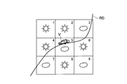
- FIGS. 9 and 10 show images of obtaining road surface condition and environmental information. Specifically, FIG. 9 shows a positional relationship between the vehicle V and a surrounding vehicle Vp traveling on a surrounding road RD. FIG. 10 shows the surrounding weather including the current position of the vehicle V.
- the road surface state determined by the surrounding vehicle Vp located in the mesh is used in the above-described road surface state labeling operation.
- the road surface state determined by the plurality of peripheral vehicles Vp (assuming that the road surface state is determined at a point on the road RD shown in FIG. 9) is determined to be one of the road surface states by majority decision.
- the determination based on the surrounding vehicle Vp is not performed in the above-described road surface state labeling operation.
- the weather in the nine meshes (or the five meshes) based on the current position of the vehicle V is determined to be any one of the weather in the meshes (any one of fine cloudy, rain, and snow) by majority decision.
- the temperature the average of each mesh is used. If there is no weather information, the determination based on weather or temperature is not performed in the above-described road surface state labeling operation.
- FIG. 11 shows a display example of the road surface state in vehicle V. Specifically, FIG. 11 shows a display example of a road surface state on the display device D mounted on the vehicle V.
- the display device D is typically various types of displays that can display a road map for car navigation. Note that the display device D may be a mobile terminal such as a smartphone.
- the display device D shows a current position P of the vehicle V and a road map around the vehicle V runs.
- the processing device 120 displays a road surface state ahead of the vehicle V in the traveling direction based on the data transmitted from the road surface state determination server 300. Specifically, the display device D displays a Wet section Sw in which the road surface is wet due to rain or the like in front of the vehicle V in the traveling direction.
- the Wet section Sw is displayed based on the data transmitted from the road surface state determination server 300, and is based on a result comprehensively determined based on the vehicle state information and the environment information described above. That is, it is possible to more accurately report the road surface state ahead of the vehicle V in the traveling direction.
- the following function and effect can be obtained. Specifically, according to the road surface state determination system 100, the road surface state (Dry, Wet, Ice, Snow) determined by the sensor unit 110 using the supplementary information (vehicle state information and environmental information), that is, the road surface The road condition acquired by the condition determination server 300 is updated.
- the road surface state (Dry, Wet, Ice, Snow) determined by the sensor unit 110 using the supplementary information (vehicle state information and environmental information), that is, the road surface
- vehicle state information and environmental information that is, the road surface
- the road condition acquired by the condition determination server 300 is updated.
- the road surface condition determination server 300 relabels the data indicating the feature amount of the road surface condition from the sensor unit 110 to the correct road surface condition. By repeating such road surface state labeling, it is possible to learn an appropriate road surface state determination algorithm in consideration of the temporal change of the pneumatic tire 10, and to generate a new determination algorithm.
- the road surface state determination server 300 determines whether or not the acquired road surface state is correct using the supplementary information (vehicle state information and environment information), and the road surface state determined by the sensor unit 110 is incorrect. If so, the road surface condition is corrected.
- the road surface condition determination server 300 can update the determination algorithm of the road surface condition based on the updated road surface condition.
- the road surface state determination server 300 updates the road surface state and the determination algorithm.
- V2V, ⁇ V2X vehicle-to-vehicle communication
- the processing device 120 The processing may be executed.
- the road surface conditions are Dry, Wet, Ice, and Snow.
- semi-wet may be included.
- Pneumatic tire 20 Tread 100 Road surface determination system 110 Sensor unit 111 Acceleration sensor 113 Internal pressure sensor 115 Temperature sensor 117 Road surface determination unit 119 Wireless communication unit 120 Processing unit 121 Wireless communication unit 123 Road surface relay unit 125 Vehicle state transmission unit 127 Road condition display control unit 200 Wireless base station 300 Road condition determination server 301 Road condition acquisition unit 303 Vehicle condition acquisition unit 305 Environment information acquisition unit 307 Road condition update unit 309 Determination algorithm update unit 311 Road condition database 313 Determination algorithm transmission unit 315 Road surface Status transmission unit 400 Network cloud
Landscapes
- Engineering & Computer Science (AREA)
- Environmental & Geological Engineering (AREA)
- Mechanical Engineering (AREA)
- Environmental Sciences (AREA)
- Biodiversity & Conservation Biology (AREA)
- Ecology (AREA)
- Atmospheric Sciences (AREA)
- Physics & Mathematics (AREA)
- Automation & Control Theory (AREA)
- Mathematical Physics (AREA)
- Transportation (AREA)
- Life Sciences & Earth Sciences (AREA)
- Control Of Driving Devices And Active Controlling Of Vehicle (AREA)
- Tires In General (AREA)
- Traffic Control Systems (AREA)
Abstract
路面状態判定システム(100)を構成する路面状態判定サーバ(300)は、加速度データを用いて、所定の判定アルゴリズムに基づいて判定された路面状態を取得する路面状態取得部(301)と、タイヤが装着されている車両の状態を示す車両状態情報、車両の周辺環境を示す環境情報、及び他の車両に装着されているタイヤの加速度データを用いて判定された路面状態の少なくとも何れかを含む補足情報を取得する車両状態取得部(303)及び環境情報取得部(305)と、補足情報を用いて、路面状態取得部(301)によって取得された路面状態を更新する路面状態更新部(307)とを備える。
Description
本発明は、タイヤが転動する路面の路面状態を判定する路面状態判定システム、路面状態判定プログラム及び路面状態判定方法に関する。
リムホイールに組み付けられた空気入りタイヤ(タイヤ)の内側面に取り付けられた加速度センサによって取得された加速度データに基づいて、路面状態(例えば、乾燥、湿潤(ウェット)、積雪(スノー)など)を判定するシステムが知られている(特許文献1参照)。
具体的には、特許文献1では、所定時間内に複数の車両から取得した加速度データを用いること、及び当該所定時間における天候などの情報を補足的に用いることによって、路面状態の判定精度を向上させている。
特許文献1に記載されたシステムによれば、路面状態の判定精度を向上させることができるが、実際には、次のような問題がある。具体的には、加速度センサが取り付けられるタイヤが、摩耗の進展、または内圧の変化など、経時的な変化を来すことによって、取得される加速度データも変化し得る。
このように、タイヤの何らかの経時的な変化によって、取得される加速度データが変化した後も既存の路面状態の判定アルゴリズムを使用し続けると、路面状態を誤判定する可能性がある。例えば、スノーである路面状態をウェットと誤判定してしまう場合が考えられる。
そこで、本発明は、このような状況に鑑みてなされたものであり、タイヤが経時的な変化を来した場合でも、路面状態の判定精度を維持し得る路面状態判定システム、路面状態判定プログラム及び路面状態判定方法の提供を目的とする。
本発明の一態様は、タイヤ(空気入りタイヤ10)の内側面に取り付けられた加速度センサ(加速度センサ111)によって取得された加速度データに基づいて、前記タイヤが転動する路面の路面状態を判定する路面状態判定システム(路面状態判定システム100)であって、前記加速度データを用いて、所定の判定アルゴリズムに基づいて判定された前記路面状態を取得する路面状態取得部(路面状態取得部301)と、前記タイヤが装着されている車両(車両V)の状態を示す車両状態情報、前記車両の周辺環境を示す環境情報、及び他の車両(周辺車両Vp)に装着されているタイヤの前記加速度データを用いて判定された前記路面状態の少なくとも何れかを含む補足情報を取得する補足情報取得部(車両状態取得部303、環境情報取得部305)と、前記補足情報を用いて、前記路面状態取得部によって取得された前記路面状態を更新する路面状態更新部(路面状態更新部307)とを備える。
本発明の一態様は、タイヤの内側面に取り付けられた加速度センサによって取得された加速度データに基づいて、前記タイヤが転動する路面の路面状態を判定する路面状態判定プログラムであって、前記加速度データを用いて、所定の判定アルゴリズムに基づいて判定された前記路面状態を取得する処理と、前記タイヤが装着されている車両の装備の動作状態を示す車両状態情報、前記車両の周辺環境を示す環境情報、及び他の車両に装着されているタイヤの前記加速度データを用いて判定された前記路面状態の少なくとも何れかを含む補足情報を取得する処理と、前記補足情報を用いて、前記路面状態を取得する処理によって取得された前記路面状態を更新する処理とをコンピュータに実行させる。
本発明の一態様は、タイヤの内側面に取り付けられた加速度センサによって取得された加速度データに基づいて、前記タイヤが転動する路面の路面状態を判定する路面状態判定方法であって、前記加速度データを用いて、所定の判定アルゴリズムに基づいて判定された前記路面状態を取得するステップと、前記タイヤが装着されている車両の装備の動作状態を示す車両状態情報、前記車両の周辺環境を示す環境情報、及び他の車両に装着されているタイヤの前記加速度データを用いて判定された前記路面状態の少なくとも何れかを含む補足情報を取得する処理と、前記補足情報を用いて、前記路面状態を取得するステップによって取得された前記路面状態を更新するステップとを含む。
以下、実施形態を図面に基づいて説明する。なお、同一の機能や構成には、同一または類似の符号を付して、その説明を適宜省略する。
(1)車両の概略構成
図1は、空気入りタイヤ10が装着された車両Vの概略側面図である。図1に示すように、車両Vには、空気入りタイヤ10が装着される。具体的には、車両Vには、リムホイール(不図示)に組み付けられた空気入りタイヤ10が装着される。
図1は、空気入りタイヤ10が装着された車両Vの概略側面図である。図1に示すように、車両Vには、空気入りタイヤ10が装着される。具体的には、車両Vには、リムホイール(不図示)に組み付けられた空気入りタイヤ10が装着される。
車両Vは、典型的には乗用自動車であるが、特に、乗用自動車に限定されない。車両Vに装着された空気入りタイヤ10は、路面Rを転動する。
空気入りタイヤ10には、加速度センサを含むセンサーユニット110が取り付けられている。
(2)路面状態判定システムの全体概略構成
図2は、本実施形態に係る路面状態判定システム100の全体概略構成図である。図2に示すように、路面状態判定システム100は、センサーユニット110、処理装置120及び路面状態判定サーバ300を含む。
図2は、本実施形態に係る路面状態判定システム100の全体概略構成図である。図2に示すように、路面状態判定システム100は、センサーユニット110、処理装置120及び路面状態判定サーバ300を含む。
路面状態判定システム100は、空気入りタイヤ10の内側面に取り付けられた加速度センサ111(図2において不図示、図3参照)によって取得された加速度データに基づいて、路面Rの路面状態を判定する。
センサーユニット110は、空気入りタイヤ10のトレッド20内側に設けられる。具体的には、センサーユニット110は、トレッド20の内側面に取り付けられる。なお、図2では、リムホイールに組み付けられた空気入りタイヤ10のタイヤ幅方向に沿った断面形状が示されている。
処理装置120は、センサーユニット110との無線による通信を実現し、センサーユニット110が検出したデータを取得する。処理装置120は、プロセッサ、メモリ、及び通信IFなどのハードウェアによって実現される。
なお、処理装置120は、通常、空気入りタイヤ10が装着される車両に設けられる。また、この場合、処理装置120は、車両Vに搭載されている電子制御ユニット(ECU)によって実現されてもよい。
路面状態判定サーバ300は、処理装置120と通信を実行する。具体的には、路面状態判定サーバ300は、ネットワーククラウド400と接続された無線基地局200を経由して、処理装置120と各種データを送受信する。
路面状態判定サーバ300の機能は、典型的には、ネットワーククラウド400上のデータセンターに設けられたサーバコンピュータによって提供し得る。
但し、路面状態判定サーバ300の機能の一部または全部は、ネットワーククラウド400上で提供されるアプリケーションサービス及びストレージサービスなどによって、仮想的に提供されても構わない。
ネットワーククラウド400は、有線通信または無線通信によって情報伝送を可能にする通信ネットワークである。ネットワーククラウド400は、典型的にはインターネットを含み、インターネット上において提供される各種の情報提供サービス(気象、交通情報など)も提供することができる。
(3)路面状態判定システムの機能ブロック構成
次に、路面状態判定システム100の機能ブロック構成について説明する。具体的には、センサーユニット110、処理装置120及び路面状態判定サーバ300の機能ブロック構成について説明する。
次に、路面状態判定システム100の機能ブロック構成について説明する。具体的には、センサーユニット110、処理装置120及び路面状態判定サーバ300の機能ブロック構成について説明する。
(3.1)センサーユニット110
図3は、センサーユニット110の機能ブロック構成図である。図3に示すように、センサーユニット110は、加速度センサ111、内圧センサ113、温度センサ115、路面状態判定部117及び無線通信部119を備える。
図3は、センサーユニット110の機能ブロック構成図である。図3に示すように、センサーユニット110は、加速度センサ111、内圧センサ113、温度センサ115、路面状態判定部117及び無線通信部119を備える。
センサーユニット110は、これらの機能を実現するデジタル信号プロセッサ(DSP)、Application Specific Integrated Circuit(ASIC)などのハードウェアモジュールによって構成できる。
加速度センサ111は、空気入りタイヤ10の所定方向の加速度を検出する。具体的には、加速度センサ111は、空気入りタイヤ10のタイヤ周方向における加速度を検出する。なお、加速度センサ111は、タイヤ径方向における加速度を検出してもよい。
加速度センサ111は、空気入りタイヤ10の内面、具体的には、トレッド20のタイヤ幅方向における中央部に設けられる。加速度センサ111としては、3軸加速度センサなど、汎用的な加速度センサを用い得る。
内圧センサ113は、リムホイールに組み付けられた空気入りタイヤ10の内圧(空気圧)を検出する。温度センサ115は、トレッド20内側面の温度を検出する。
内圧センサ113及び温度センサ115は、一般的なTPMS(tire pressure monitoring system)などに用いられているセンサと同様である。
路面状態判定部117は、路面Rの状態(路面状態)を判定する。具体的には、路面状態判定部117は、空気入りタイヤ10が路面Rを転動する際に、加速度センサ111によって検出された加速度を示すデータ(加速度データ)に基づいて、路面状態を判定する。
本実施形態では、路面状態判定部117は、路面状態が、(i)乾燥(Dry)、(ii)湿潤(Wet)、(iii)凍結(Ice)または(iv)積雪(Snow)の何れであるかを判定する。
路面状態判定部117は、加速度データに基づいて路面状態を判定する判定アルゴリズム(所定の判定アルゴリズム)を保持し、当該判定アルゴリズムに基づいて路面状態を判定する。
なお、路面状態判定部117は、内圧センサ113によって検出された内圧を示すデータ、及び温度センサ115によって検出された温度を示すデータを補足的に用いて路面状態を判定してもよい。
また、路面状態判定部117は、路面状態判定サーバ300から路面状態の新たな判定アルゴリズムを受信した場合、当該新たな判定アルゴリズムによって既存の判定アルゴリズムを書き換えること、つまり、新たな判定アルゴリズムをインストールすることができる。
無線通信部119は、処理装置120との無線通信を実行する。無線通信部119による無線通信方式は、特に限定されない。例えば、通信方式としては、TPMSなどに用いられているLF波(低周波)を利用する方式や、近距離無線通信の規格に沿った方式が挙げられる。
また、無線通信部119は、空気入りタイヤ10(つまり、センサーユニット110)を識別する識別情報(タイヤID)を含むデータを送信することができる。
本実施形態では、無線通信部119は、路面状態判定部117によって判定された路面状態を示すデータを送信したり、路面状態を判定する判定アルゴリズムを受信したりすることができる。なお、無線通信部119は、内圧センサ113によって検出された内圧を示すデータ、及び温度センサ115によって検出された温度を示すデータを送信してもよい。
(3.2)処理装置120
図4は、処理装置120の機能ブロック構成図である。図4に示すように、無線通信部121、路面状態中継部123、車両状態送信部125及び路面状態表示制御部127を備える。
図4は、処理装置120の機能ブロック構成図である。図4に示すように、無線通信部121、路面状態中継部123、車両状態送信部125及び路面状態表示制御部127を備える。
無線通信部121は、センサーユニット110との無線通信を実行する。また、無線通信部121は、無線基地局200との無線通信を実行する。つまり、無線通信部121は、センサーユニット110との近距離無線通信、及び無線基地局200との広帯域無線通信(Long Term Evolution(LTE)などの移動通信ネットワーク)をサポートする。
路面状態中継部123は、センサーユニット110から送信された路面状態を示すデータを路面状態判定サーバ300に中継する。
具体的には、路面状態中継部123は、路面状態の判定結果(Dry, Wet, Ice, Snow)と、加速度データに基づいて抽出された路面状態の特徴量を示すデータとを中継する。路面状態の特徴量を示すデータとは、例えば、加速度センサ111の時系列波形に含まれる複数の特定周波数帯域における振動の大きさ(帯域値)などであり、当該路面状態の特徴を端的に示すデータであればよい。
なお、通信環境などが整っている場合、路面状態中継部123は、センサーユニット110から加速度データ自体を示す生データを受信し、路面状態を示すデータとして当該生データを中継してもよい。
また、路面状態中継部123は、路面状態判定サーバ300から送信された路面状態の判定アルゴリズムをセンサーユニット110に中継することができる。
車両状態送信部125は、車両Vの状態を示す情報(車両状態情報)を路面状態判定サーバ300に送信する。車両Vの状態を示す情報には、車両Vの現在位置(位置情報)、車外温度、及び車両Vの各種装備の動作状態を示す情報(装備動作情報)が含まれる。
各種装備としては、例えば、ワイパー、灯火類(特に、ヘッドライト及びフォグランプ)、空調システム(特に、デフロスタ)、ウインドシールドまたはワイパーのデアイサ、車載カメラなどが挙げられる。
車両状態送信部125は、これらの車両装備の動作状況(オン/オフなど)を示す情報を送信する。
なお、本実施形態では、「情報」とは、それ自体が一定の意味を有する場合において主に用い、「データ」とは、加工などが必要な場合があり、それ自体が一定の意味を有さない場合において主に用いる。
路面状態表示制御部127は、路面状態判定サーバ300から送信されたデータに基づいて路面状態の表示制御を実行する。具体的には、路面状態表示制御部127は、当該データに基づいて、車両Vに搭載されている表示装置D(図11参照)に道路RDの路面Rの路面状態を表示させる。
(3.3)路面状態判定サーバ300
図5は、路面状態判定サーバ300の機能ブロック構成図である。図5に示すように、路面状態判定サーバ300は、路面状態取得部301、車両状態取得部303、環境情報取得部305、路面状態更新部307、判定アルゴリズム更新部309、路面状態データベース311、判定アルゴリズム送信部313及び路面状態送信部315を備える。
図5は、路面状態判定サーバ300の機能ブロック構成図である。図5に示すように、路面状態判定サーバ300は、路面状態取得部301、車両状態取得部303、環境情報取得部305、路面状態更新部307、判定アルゴリズム更新部309、路面状態データベース311、判定アルゴリズム送信部313及び路面状態送信部315を備える。
上述したように、これらの機能ブロックは、サーバコンピュータなどのハードウェア上においてコンピュータプログラム(ソフトウェア)を実行することによって実現できる。
具体的には、路面状態判定サーバ300は、ハードウェア要素として、プロセッサ、メモリ、入力デバイス、ディスプレイ及び外部インターフェースを備える。また、当該コンピュータプログラム(ソフトウェア)は、通信ネットワークを介して提供されてもよいし、光ディスク、ハードディスクドライブまたはフラッシュメモリなどのコンピュータ読み取り可能な記録媒体に記録されていてもよい。
路面状態取得部301は、センサーユニット110によって判定された路面状態を取得する。具体的には、路面状態取得部301は、処理装置120によって中継された当該路面状態を示すデータ(判定結果及び路面状態の特徴量を示すデータ)を取得する。
つまり、路面状態取得部301が取得する路面状態は、加速度センサ111によって取得された加速度データを用いて、所定の判定アルゴリズムに基づいて判定されたものである。
路面状態取得部301は、実際には、複数の車両Vから同様の路面状態を示すデータを取得する。
車両状態取得部303は、車両Vまたは車両Vの周辺を走行する周辺車両Vp(図9及び図10参照)の状態を取得する。具体的には、車両状態取得部303は、処理装置120から送信された車両Vの状態を示す情報を取得する。
つまり、車両状態取得部303は、空気入りタイヤ10が装着されている車両Vの状態を示す車両状態情報を取得する。車両状態情報には、上述したように、車両Vの装備の動作状態を示す情報(装備動作情報)が含まれる。
また、車両状態取得部303は、車両V以外の他の車両、具体的には、車両Vの周辺を走行する周辺車両Vpに装着されているタイヤの加速度データを用いて判定された路面状態を示す情報を取得することもできる。
なお、周辺車両Vpとは、特に限定されないが、例えば、車両Vを中心とした半径1km以内の領域を走行中の車両、或いは車両Vが走行している道路の前方5km以内の領域を走行中の車両などとすることができる。
環境情報取得部305は、車両Vの周辺環境を示す環境情報を取得する。具体的には、環境情報取得部305は、車両Vの現在位置の気象情報(天候)、車両Vが走行する道路の交通情報、及び速度または通行規制情報などを取得する。
なお、当該環境情報は、ネットワーククラウド400上の各種サービスを利用して取得してもよいし、取得可能な情報については、処理装置120を介して車両V側から取得してもよい。
本実施形態では、車両状態取得部303及び環境情報取得部305によって、路面状態を補足する補足情報(車両状態情報及び環境情報)を取得する補足情報取得部が構成される。
路面状態更新部307は、車両状態取得部303及び環境情報取得部305によって取得された補足情報を用いて、路面状態取得部301によって取得された路面状態を更新する。
具体的には、路面状態更新部307は、車両状態取得部303によって取得された車両状態情報、及び環境情報取得部305によって取得された環境情報を用いて、当該路面状態を更新する。
より具体的には、路面状態更新部307は、車両状態情報または環境情報を用いて、路面状態取得部によって取得された路面状態が正しいか否かを判定する。
路面状態更新部307は、路面状態取得部301によって取得された路面状態が誤っていると判定した場合、当該路面状態を修正する。例えば、路面状態取得部301によって取得された路面状態がWetであり、環境情報を用いて路面状態がSnowであると断定できる場合、当該路面状態をSnowに修正する。
また、路面状態更新部307は、当該路面状態の特徴量を示すデータ(或いは加速度データ自体を示す生データ)をSnowとラベリングし、路面状態データベース311に格納する。
一方、路面状態更新部307は、路面状態取得部301によって取得された路面状態が正しいと判定した場合、路面状態を修正しない。
但し、この場合でも、路面状態更新部307は、当該路面状態の特徴量を示すデータ(或いは加速度データ自体を示す生データ)を、路面状態取得部301によって取得された路面状態としてラベリングし、路面状態データベース311に格納してもよい。これにより、空気入りタイヤ10の経時的な変化に応じて、適切な路面状態の判定アルゴリズムが生成できる。
なお、車両Vのドライバーが実際の路面状態を観察して通知するなどの方法を用いない限り、路面状態更新部307による完璧なラベリングは困難である。そこで、本実施形態では、路面状態取得部301によって取得された元の路面状態の判定結果に加えて、補足情報(車両状態情報及び環境情報)を用いることによって、極力正しい路面状態のラベリングを実現する。
判定アルゴリズム更新部309は、路面状態更新部307によって更新された、つまり、ラベリング後の路面状態に基づいて、路面状態の判定アルゴリズム(所定の判定アルゴリズム)を更新する。
具体的には、判定アルゴリズム更新部309は、路面状態更新部307によってラベリングされた路面状態の特徴量を示すデータを用いて、当該判定アルゴリズムを更新する。なお、当該判定アルゴリズムは、判定器などと呼んでもよい。
つまり、路面状態更新部307が、上述したような路面状態のラベリングを繰り返すことによって、判定アルゴリズム更新部309は、空気入りタイヤ10の経時的な変化を考慮した適切な路面状態の判定アルゴリズムを学習できる。
判定アルゴリズム更新部309は、路面状態データベース311に格納されている路面状態のラベリングデータ、具体的には、路面状態と、当該路面状態の特徴量を示すデータとが対応付けられたデータの中から、タイヤIDを用いてタイヤ毎のラベリングデータを取得する。
判定アルゴリズム更新部309は、センサーユニット110において動作中の判定アルゴリズムによる路面状態の判定精度が設定された値を下回った場合、以前用いたラベリングデータも含めて再学習し、判定精度が向上した新たな判定アルゴリズム(判定器)をタイヤ毎(車両V毎)に生成する。
なお、センサーユニット110において動作中の判定アルゴリズムによる路面状態の判定精度が設定された値を下回ることは、路面状態更新部307による路面状態の判定結果に基づいて判断できる。
路面状態データベース311は、路面状態に関するデータによって構成されるデータベースである。特に、本実施形態では、路面状態データベース311は、タイヤIDと紐付けられたタイヤ毎のラベリングデータを保持する。
路面状態データベース311によって保持されるラベリングデータは、路面状態の特徴量を示すデータに対して路面状態を示す情報がラベリングされており、判定アルゴリズム更新部309による判定アルゴリズムの再学習(新たな判定アルゴリズムの生成と呼んでもよい)において、教師データとして用いられる。
判定アルゴリズム送信部313は、判定アルゴリズム更新部309によって更新(生成)されたタイヤ毎の路面状態の判定アルゴリズムを車両Vに送信する。具体的には、判定アルゴリズム送信部313は、処理装置120を経由して、新たな判定アルゴリズムのデータをセンサーユニット110に送信する。
路面状態送信部315は、路面Rの状態を示すデータを処理装置120に送信する。具体的には、路面状態送信部315は、車両Vに搭載されている表示装置D(図11参照)での表示に必要な路面Rの状態を示すデータを送信する。
例えば、路面状態送信部315は、特定の路面状態(例えば、Wet)である道路の区間を示す情報を送信することができる。なお、当該道路の区間は、路面状態取得部301、車両状態取得部303及び環境情報取得部305によって取得されたデータまたは情報を複合的に用いることによって判定することができる。
(4)路面状態判定システムの動作
次に、路面状態判定システム100の動作について説明する。具体的には、路面状態判定システム100による路面状態の判定アルゴリズムの更新シーケンス、路面状態のラベリング動作フロー、及び車両Vでの路面状態の表示例について説明する。
次に、路面状態判定システム100の動作について説明する。具体的には、路面状態判定システム100による路面状態の判定アルゴリズムの更新シーケンス、路面状態のラベリング動作フロー、及び車両Vでの路面状態の表示例について説明する。
(4.1)路面状態の判定アルゴリズムの更新シーケンス
図6は、路面状態判定システム100による路面状態の判定アルゴリズムの更新シーケンスを示す。
図6は、路面状態判定システム100による路面状態の判定アルゴリズムの更新シーケンスを示す。
図6に示すように、センサーユニット110は、加速度データなどに基づいて判定された路面状態に関するデータを処理装置120に送信する(S10)。具体的には、センサーユニット110は、路面状態の判定結果(Dry, Wet, Ice, Snow)と、加速度データに基づいて抽出された路面状態の特徴量を示すデータを処理装置120に送信する。
処理装置120は、車両Vの状態を示す情報(車両状態情報)を取得(S20)し、センサーユニット110から受信した路面状態に関するデータとともに、路面状態判定サーバ300に送信する(S30)。
路面状態判定サーバ300は、センサーユニット110から受信した路面状態に関するデータに含まれる路面状態の判定結果(Dry, Wet, Ice, Snow)を、処理装置120から受信した車両状態情報(装備動作情報を含む)、及びネットワーククラウド400上から取得した環境情報(車両Vの現在位置の気象情報など)に基づいて、当該路面状態を更新する(S40)。
具体的には、路面状態判定サーバ300は、車両状態情報及び環境情報を用いて、センサーユニット110から受信した路面状態の判定結果が正しいか否かを判定し、当該路面状態の特徴量を示すデータにラベリングする(図6に簡略化したイメージを示す)。なお、路面状態のラベリング動作については、さらに後述する。
路面状態判定サーバ300は、ラベリング後の路面状態に関するデータに基づいて、路面状態の判定アルゴリズムを更新する(S50)。具体的には、ラベリングされた路面状態の特徴量を示すデータを用いて、当該判定アルゴリズムを更新する。
路面状態判定サーバ300は、更新した判定アルゴリズム(新判定アルゴリズム)を処理装置120に送信する(S60)。
処理装置120は、受信した新判定アルゴリズムをセンサーユニット110に中継する(S70)。
センサーユニット110は、受信した新判定アルゴリズムによって既存の判定アルゴリズムを書き換える、つまり、新たな判定アルゴリズムをインストールする(S80)。
センサーユニット110は、新判定アルゴリズムを用いて判定された路面状態に関するデータを処理装置120に送信する(S90)。
その後、上述したS20以降の処理が繰り返される。
(4.2)路面状態のラベリング動作フロー
図7及び図8は、路面状態判定サーバ300による路面状態のラベリング動作フローを示す。図7及び図8に示すように、路面状態判定サーバ300は、センサーユニット110による路面状態の判定結果(Dry, Wet, Ice, Snow)に基づいた処理(S110~S140)を実行する。
図7及び図8は、路面状態判定サーバ300による路面状態のラベリング動作フローを示す。図7及び図8に示すように、路面状態判定サーバ300は、センサーユニット110による路面状態の判定結果(Dry, Wet, Ice, Snow)に基づいた処理(S110~S140)を実行する。
具体的には、路面状態判定サーバ300は、車外温度及び天候気温を判定した上で、センサーユニット110による路面状態の判定結果がWetか否かを判定する(S110)。
なお、車外温度とは、処理装置120から送信された車両V外部の温度(車両Vにおいて測定された外気温)であり、気温とは、気象情報などから得られる車両Vが位置する領域の温度である。
路面状態の判定結果がWetである場合、路面状態判定サーバ300は、車両Vの装備(ここでは、ワイパーの例を示す)の動作状況、車両Vの現在位置周辺の天候、及び車両Vの周辺を走行する周辺車両Vp(図9及び図10参照)の路面状態の判定結果に基づいて、センサーユニット110から送信された路面状態の特徴量を示すデータをWetとラベリングするか否かを判定する。
路面状態判定サーバ300は、路面状態の判定結果がDry, Ice, Snowである場合についても、同様の処理を実行する(S120, S130及びS140)。
この結果、センサーユニット110による路面状態の判定結果は、車両状態情報または環境情報に基づいて、異なる路面状態にラベリングされる場合がある。
図9及び図10は、路面状態及び環境情報の取得イメージを示す。具体的には、図9は、車両Vと、周辺の道路RDを走行する周辺車両Vpとの位置関係を示す。図10は、車両Vの現在位置を含む周辺の天候を示す。
図9及び図10に示す例では、車両Vの現在位置を基準とした9つのメッシュ状の周辺領域が規定されている。なお、メッシュのサイズは、任意に調整可能である。また、9つ全てのメッシュを用いずに、車両Vの現在位置を基準とした5つのメッシュ(図中の2, 4, 5, 6, 8)のみを用いてもよい。
当該メッシュ内に位置する周辺車両Vpによって判定された路面状態が、上述した路面状態のラベリング動作において用いられる。複数の周辺車両Vpによって判定された路面状態(図9に示す道路RD上の点の位置において判定されたことを想定)は、多数決によって何れかの路面状態と判定される。また、周辺車両Vpが存在しない場合には、上述した路面状態のラベリング動作において、周辺車両Vpに基づく判定は行われない。
車両Vの現在位置を基準とした9つのメッシュ内(または5つのメッシュ内)の天候は、各メッシュ内の天候も多数決によって何れか(晴曇、雨、雪の何れか)に判定される。
なお、気温については、各メッシュの平均が用いられる。また、気象情報が存在しない場合には、上述した路面状態のラベリング動作において、天候または気温に基づく判定は行われない。
なお、気温については、各メッシュの平均が用いられる。また、気象情報が存在しない場合には、上述した路面状態のラベリング動作において、天候または気温に基づく判定は行われない。
(4.3)車両Vでの路面状態の表示例
図11は、車両Vでの路面状態の表示例を示す。具体的には、図11は、車両Vに搭載されている表示装置Dにおける路面状態の表示例を示す。表示装置Dは、典型的には、カーナビゲーション用の道路地図を表示できる各種のディスプレイである。なお、表示装置Dは、スマートフォンなどの携帯端末でもよい。
図11は、車両Vでの路面状態の表示例を示す。具体的には、図11は、車両Vに搭載されている表示装置Dにおける路面状態の表示例を示す。表示装置Dは、典型的には、カーナビゲーション用の道路地図を表示できる各種のディスプレイである。なお、表示装置Dは、スマートフォンなどの携帯端末でもよい。
図11に示すように、表示装置Dには、車両Vの現在位置P、及び車両Vが走行する周辺の道路地図が示されている。
また、表示装置Dには、処理装置120が路面状態判定サーバ300から送信されたデータに基づいて、車両Vの進行方向前方の路面状態が表示される。具体的には、表示装置Dには、車両Vの進行方向前方に、路面が降雨などによって濡れているWet区間Swが表示されている。
Wet区間Swは、路面状態判定サーバ300から送信されたデータに基づいて表示されており、上述した車両状態情報及び環境情報に基づいて総合的に判断された結果に基づくものである。つまり、車両Vの進行方向前方の路面状態をより正確に報知し得る。
(5)作用・効果
上述した実施形態によれば、以下の作用効果が得られる。具体的には、路面状態判定システム100によれば、補足情報(車両状態情報及び環境情報)を用いて、センサーユニット110によって判定された路面状態(Dry, Wet, Ice, Snow)、つまり、路面状態判定サーバ300が取得した路面状態が更新される。
上述した実施形態によれば、以下の作用効果が得られる。具体的には、路面状態判定システム100によれば、補足情報(車両状態情報及び環境情報)を用いて、センサーユニット110によって判定された路面状態(Dry, Wet, Ice, Snow)、つまり、路面状態判定サーバ300が取得した路面状態が更新される。
具体的には、路面状態判定サーバ300は、センサーユニット110から路面状態の特徴量を示すデータを正しい路面状態にラベリングし直す。このような路面状態のラベリングを繰り返すことによって、空気入りタイヤ10の経時的な変化を考慮した適切な路面状態の判定アルゴリズムを学習し、新たな判定アルゴリズムを生成することができる。
これにより、タイヤが経時的な変化を来した場合でも、路面状態の判定精度を維持し得る。
本実施形態では、路面状態判定サーバ300は、補足情報(車両状態情報及び環境情報)を用いて、取得した路面状態が正しいか否かを判定し、センサーユニット110によって判定された路面状態が誤っていると判定した場合、当該路面状態を修正する。
このため、修正された路面状態に関するデータに基づいて判定アルゴリズムを継続的に学習することによって、路面状態が誤判定される可能性を確実に低減し得る。
本実施形態では、路面状態判定サーバ300は、更新された路面状態に基づいて、路面状態の判定アルゴリズムを更新することができる。
このため、空気入りタイヤ10の経時的な変化を考慮した適切な路面状態の判定アルゴリズムを速やかに準備でき、タイヤが経時的な変化を来した場合でも、路面状態の判定精度を確実に維持し得る。
(6)その他の実施形態
以上、実施例に沿って本発明の内容を説明したが、本発明はこれらの記載に限定されるものではなく、種々の変形及び改良が可能であることは、当業者には自明である。
以上、実施例に沿って本発明の内容を説明したが、本発明はこれらの記載に限定されるものではなく、種々の変形及び改良が可能であることは、当業者には自明である。
例えば、上述した実施形態では、路面状態判定サーバ300において路面状態及び判定アルゴリズムの更新が実行されていたが、高速な車車間通信(V2V, V2X)などが可能であれば、処理装置120において当該処理が実行されても構わない。
上述した実施形態では、路面状態は、Dry, Wet, Ice, Snowの4つであったが、これらに加え、半湿(Semi-wet)が含まれてもよく、また、Snowは、シャーベット状、積雪及び圧雪などに細分化されてもよい。
上記のように、本発明の実施形態を記載したが、この開示の一部をなす論述及び図面はこの発明を限定するものであると理解すべきではない。この開示から当業者には様々な代替実施の形態、実施例及び運用技術が明らかとなろう。
10 空気入りタイヤ
20 トレッド
100 路面状態判定システム
110 センサーユニット
111 加速度センサ
113 内圧センサ
115 温度センサ
117 路面状態判定部
119 無線通信部
120 処理装置
121 無線通信部
123 路面状態中継部
125 車両状態送信部
127 路面状態表示制御部
200 無線基地局
300 路面状態判定サーバ
301 路面状態取得部
303 車両状態取得部
305 環境情報取得部
307 路面状態更新部
309 判定アルゴリズム更新部
311 路面状態データベース
313 判定アルゴリズム送信部
315 路面状態送信部
400 ネットワーククラウド
20 トレッド
100 路面状態判定システム
110 センサーユニット
111 加速度センサ
113 内圧センサ
115 温度センサ
117 路面状態判定部
119 無線通信部
120 処理装置
121 無線通信部
123 路面状態中継部
125 車両状態送信部
127 路面状態表示制御部
200 無線基地局
300 路面状態判定サーバ
301 路面状態取得部
303 車両状態取得部
305 環境情報取得部
307 路面状態更新部
309 判定アルゴリズム更新部
311 路面状態データベース
313 判定アルゴリズム送信部
315 路面状態送信部
400 ネットワーククラウド
Claims (5)
- タイヤの内側面に取り付けられた加速度センサによって取得された加速度データに基づいて、前記タイヤが転動する路面の路面状態を判定する路面状態判定システムであって、
前記加速度データを用いて、所定の判定アルゴリズムに基づいて判定された前記路面状態を取得する路面状態取得部と、
前記タイヤが装着されている車両の状態を示す車両状態情報、前記車両の周辺環境を示す環境情報、及び他の車両に装着されているタイヤの前記加速度データを用いて判定された前記路面状態の少なくとも何れかを含む補足情報を取得する補足情報取得部と、
前記補足情報を用いて、前記路面状態取得部によって取得された前記路面状態を更新する路面状態更新部と
を備える路面状態判定システム。 - 前記路面状態更新部は、
前記補足情報を用いて、前記路面状態取得部によって取得された前記路面状態が正しいか否かを判定し、
前記路面状態が誤っていると判定した場合、前記路面状態を修正する請求項1に記載の路面状態判定システム。 - 前記路面状態更新部によって更新された前記路面状態に基づいて、前記所定の判定アルゴリズムを更新する判定アルゴリズム更新部を備える請求項1または2に記載の路面状態判定システム。
- タイヤの内側面に取り付けられた加速度センサによって取得された加速度データに基づいて、前記タイヤが転動する路面の路面状態を判定する路面状態判定プログラムであって、
前記加速度データを用いて、所定の判定アルゴリズムに基づいて判定された前記路面状態を取得する処理と、
前記タイヤが装着されている車両の装備の動作状態を示す車両状態情報、前記車両の周辺環境を示す環境情報、及び他の車両に装着されているタイヤの前記加速度データを用いて判定された前記路面状態の少なくとも何れかを含む補足情報を取得する処理と、
前記補足情報を用いて、前記路面状態を取得する処理によって取得された前記路面状態を更新する処理と
をコンピュータに実行させる路面状態判定プログラム。 - タイヤの内側面に取り付けられた加速度センサによって取得された加速度データに基づいて、前記タイヤが転動する路面の路面状態を判定する路面状態判定方法であって、
前記加速度データを用いて、所定の判定アルゴリズムに基づいて判定された前記路面状態を取得するステップと、
前記タイヤが装着されている車両の装備の動作状態を示す車両状態情報、前記車両の周辺環境を示す環境情報、及び他の車両に装着されているタイヤの前記加速度データを用いて判定された前記路面状態の少なくとも何れかを含む補足情報を取得する処理と、
前記補足情報を用いて、前記路面状態を取得するステップによって取得された前記路面状態を更新するステップと
を含む路面状態判定方法。
Applications Claiming Priority (2)
| Application Number | Priority Date | Filing Date | Title |
|---|---|---|---|
| JP2018158044A JP2020034275A (ja) | 2018-08-27 | 2018-08-27 | 路面状態判定システム、路面状態判定プログラム及び路面状態判定方法 |
| JP2018-158044 | 2018-08-27 |
Publications (1)
| Publication Number | Publication Date |
|---|---|
| WO2020045035A1 true WO2020045035A1 (ja) | 2020-03-05 |
Family
ID=69644959
Family Applications (1)
| Application Number | Title | Priority Date | Filing Date |
|---|---|---|---|
| PCT/JP2019/031406 Ceased WO2020045035A1 (ja) | 2018-08-27 | 2019-08-08 | 路面状態判定システム、路面状態判定プログラム及び路面状態判定方法 |
Country Status (2)
| Country | Link |
|---|---|
| JP (1) | JP2020034275A (ja) |
| WO (1) | WO2020045035A1 (ja) |
Families Citing this family (1)
| Publication number | Priority date | Publication date | Assignee | Title |
|---|---|---|---|---|
| JP7679725B2 (ja) * | 2021-08-17 | 2025-05-20 | 住友ゴム工業株式会社 | タイヤ状態判定システム、タイヤ状態判定装置、タイヤ状態判定方法、及びプログラム |
Citations (4)
| Publication number | Priority date | Publication date | Assignee | Title |
|---|---|---|---|---|
| JP2007309832A (ja) * | 2006-05-19 | 2007-11-29 | Fujitsu Ten Ltd | 路面状態判定装置及び路面状態判定方法 |
| JP2008143508A (ja) * | 2006-11-14 | 2008-06-26 | Yuki Center | 路面状況判定方法及びその装置 |
| JP2009288844A (ja) * | 2008-05-27 | 2009-12-10 | Honda Motor Co Ltd | 道路形状学習装置 |
| JP2018004418A (ja) * | 2016-06-30 | 2018-01-11 | 株式会社ブリヂストン | 路面状態判別方法 |
Family Cites Families (4)
| Publication number | Priority date | Publication date | Assignee | Title |
|---|---|---|---|---|
| JP2007153034A (ja) * | 2005-12-01 | 2007-06-21 | Toyota Motor Corp | タイヤ摩耗状態判定装置 |
| JP2008114666A (ja) * | 2006-11-01 | 2008-05-22 | Aisin Aw Co Ltd | 劣化状態判定装置 |
| JP6392623B2 (ja) * | 2014-10-06 | 2018-09-19 | 株式会社ブリヂストン | 路面状態判別システム |
| US9995654B2 (en) * | 2015-07-08 | 2018-06-12 | The Goodyear Tire & Rubber Company | Tire and vehicle sensor-based vehicle state estimation system and method |
-
2018
- 2018-08-27 JP JP2018158044A patent/JP2020034275A/ja active Pending
-
2019
- 2019-08-08 WO PCT/JP2019/031406 patent/WO2020045035A1/ja not_active Ceased
Patent Citations (4)
| Publication number | Priority date | Publication date | Assignee | Title |
|---|---|---|---|---|
| JP2007309832A (ja) * | 2006-05-19 | 2007-11-29 | Fujitsu Ten Ltd | 路面状態判定装置及び路面状態判定方法 |
| JP2008143508A (ja) * | 2006-11-14 | 2008-06-26 | Yuki Center | 路面状況判定方法及びその装置 |
| JP2009288844A (ja) * | 2008-05-27 | 2009-12-10 | Honda Motor Co Ltd | 道路形状学習装置 |
| JP2018004418A (ja) * | 2016-06-30 | 2018-01-11 | 株式会社ブリヂストン | 路面状態判別方法 |
Also Published As
| Publication number | Publication date |
|---|---|
| JP2020034275A (ja) | 2020-03-05 |
Similar Documents
| Publication | Publication Date | Title |
|---|---|---|
| EP2920040B1 (en) | Augmenting adas features of a vehicle with image processing support in on-board vehicle platform | |
| US20170349148A1 (en) | Method and apparatus for detecting road condition data and weather condition data using vehicular crowd-sensing | |
| CN107209856B (zh) | 环境场景状况检测 | |
| US9897453B2 (en) | Position information correcting device and position information correcting application program product | |
| JP6971020B2 (ja) | 異常検出装置および異常検出方法 | |
| US10876845B2 (en) | Personalized smart navigation for motor vehicles | |
| US20170232974A1 (en) | Drive assistance system and center | |
| CN109935100B (zh) | 对基础设施照明的车辆监测的系统及方法 | |
| US10486586B1 (en) | Control of vehicle headlights based on weather conditions | |
| CN107415956A (zh) | 用于检测和传送非连接车辆的打滑的系统和方法 | |
| US20190047575A1 (en) | Method for determining a coefficient of friction for a contact between a tire of a vehicle and a roadway, and method for controlling a vehicle function of a vehicle | |
| CN108454329B (zh) | 轮胎诊断系统 | |
| CN115571144A (zh) | 车辆的事故强度估计 | |
| CN113264042B (zh) | 隐藏危险情况警示 | |
| US9956833B2 (en) | In-vehicle reporting apparatus and reporting system | |
| CN112489395A (zh) | 一种道路颠簸的预警方法、装置及存储介质 | |
| CN103121382A (zh) | 一种汽车轮胎压力检测系统 | |
| WO2020045035A1 (ja) | 路面状態判定システム、路面状態判定プログラム及び路面状態判定方法 | |
| CN106103142A (zh) | 用于提供数据的方法、装置、计算机程序和计算机程序产品 | |
| WO2020217953A1 (ja) | 車両用装置、車両用プログラムおよび記憶媒体 | |
| US10919349B2 (en) | Tire chain attachment determination device | |
| CN112644501B (zh) | 一种车辆控制方法、装置、设备及计算机存储介质 | |
| JP7139794B2 (ja) | スケールファクタ学習装置、スケールファクタ学習プログラムおよび記憶媒体 | |
| US20250297923A1 (en) | Prediction and identification of potential semi-trailer truck system anomalies | |
| CN103264622A (zh) | 用气门嘴颜色标记轮胎位置的轮胎压力温度监测方法 |
Legal Events
| Date | Code | Title | Description |
|---|---|---|---|
| 121 | Ep: the epo has been informed by wipo that ep was designated in this application |
Ref document number: 19854696 Country of ref document: EP Kind code of ref document: A1 |
|
| NENP | Non-entry into the national phase |
Ref country code: DE |
|
| 122 | Ep: pct application non-entry in european phase |
Ref document number: 19854696 Country of ref document: EP Kind code of ref document: A1 |