WO2020044933A1 - Object comparison device and object comparison method - Google Patents
Object comparison device and object comparison method Download PDFInfo
- Publication number
- WO2020044933A1 WO2020044933A1 PCT/JP2019/030254 JP2019030254W WO2020044933A1 WO 2020044933 A1 WO2020044933 A1 WO 2020044933A1 JP 2019030254 W JP2019030254 W JP 2019030254W WO 2020044933 A1 WO2020044933 A1 WO 2020044933A1
- Authority
- WO
- WIPO (PCT)
- Prior art keywords
- image
- matching
- tablet
- unit
- display
- Prior art date
Links
Images


Classifications
-
- G—PHYSICS
- G06—COMPUTING; CALCULATING OR COUNTING
- G06T—IMAGE DATA PROCESSING OR GENERATION, IN GENERAL
- G06T7/00—Image analysis
- G06T7/0002—Inspection of images, e.g. flaw detection
- G06T7/0004—Industrial image inspection
- G06T7/001—Industrial image inspection using an image reference approach
-
- A—HUMAN NECESSITIES
- A61—MEDICAL OR VETERINARY SCIENCE; HYGIENE
- A61J—CONTAINERS SPECIALLY ADAPTED FOR MEDICAL OR PHARMACEUTICAL PURPOSES; DEVICES OR METHODS SPECIALLY ADAPTED FOR BRINGING PHARMACEUTICAL PRODUCTS INTO PARTICULAR PHYSICAL OR ADMINISTERING FORMS; DEVICES FOR ADMINISTERING FOOD OR MEDICINES ORALLY; BABY COMFORTERS; DEVICES FOR RECEIVING SPITTLE
- A61J1/00—Containers specially adapted for medical or pharmaceutical purposes
- A61J1/03—Containers specially adapted for medical or pharmaceutical purposes for pills or tablets
-
- A—HUMAN NECESSITIES
- A61—MEDICAL OR VETERINARY SCIENCE; HYGIENE
- A61J—CONTAINERS SPECIALLY ADAPTED FOR MEDICAL OR PHARMACEUTICAL PURPOSES; DEVICES OR METHODS SPECIALLY ADAPTED FOR BRINGING PHARMACEUTICAL PRODUCTS INTO PARTICULAR PHYSICAL OR ADMINISTERING FORMS; DEVICES FOR ADMINISTERING FOOD OR MEDICINES ORALLY; BABY COMFORTERS; DEVICES FOR RECEIVING SPITTLE
- A61J7/00—Devices for administering medicines orally, e.g. spoons; Pill counting devices; Arrangements for time indication or reminder for taking medicine
- A61J7/0076—Medicament distribution means
- A61J7/0084—Medicament distribution means for multiple medicaments
-
- G—PHYSICS
- G01—MEASURING; TESTING
- G01N—INVESTIGATING OR ANALYSING MATERIALS BY DETERMINING THEIR CHEMICAL OR PHYSICAL PROPERTIES
- G01N21/00—Investigating or analysing materials by the use of optical means, i.e. using sub-millimetre waves, infrared, visible or ultraviolet light
- G01N21/84—Systems specially adapted for particular applications
- G01N21/85—Investigating moving fluids or granular solids
-
- G—PHYSICS
- G01—MEASURING; TESTING
- G01N—INVESTIGATING OR ANALYSING MATERIALS BY DETERMINING THEIR CHEMICAL OR PHYSICAL PROPERTIES
- G01N21/00—Investigating or analysing materials by the use of optical means, i.e. using sub-millimetre waves, infrared, visible or ultraviolet light
- G01N21/84—Systems specially adapted for particular applications
- G01N21/88—Investigating the presence of flaws or contamination
-
- G—PHYSICS
- G06—COMPUTING; CALCULATING OR COUNTING
- G06F—ELECTRIC DIGITAL DATA PROCESSING
- G06F18/00—Pattern recognition
- G06F18/20—Analysing
- G06F18/22—Matching criteria, e.g. proximity measures
-
- G—PHYSICS
- G06—COMPUTING; CALCULATING OR COUNTING
- G06T—IMAGE DATA PROCESSING OR GENERATION, IN GENERAL
- G06T7/00—Image analysis
- G06T7/0002—Inspection of images, e.g. flaw detection
- G06T7/0012—Biomedical image inspection
-
- G—PHYSICS
- G06—COMPUTING; CALCULATING OR COUNTING
- G06T—IMAGE DATA PROCESSING OR GENERATION, IN GENERAL
- G06T7/00—Image analysis
- G06T7/30—Determination of transform parameters for the alignment of images, i.e. image registration
-
- G—PHYSICS
- G06—COMPUTING; CALCULATING OR COUNTING
- G06V—IMAGE OR VIDEO RECOGNITION OR UNDERSTANDING
- G06V10/00—Arrangements for image or video recognition or understanding
- G06V10/20—Image preprocessing
- G06V10/255—Detecting or recognising potential candidate objects based on visual cues, e.g. shapes
-
- G—PHYSICS
- G06—COMPUTING; CALCULATING OR COUNTING
- G06V—IMAGE OR VIDEO RECOGNITION OR UNDERSTANDING
- G06V10/00—Arrangements for image or video recognition or understanding
- G06V10/20—Image preprocessing
- G06V10/26—Segmentation of patterns in the image field; Cutting or merging of image elements to establish the pattern region, e.g. clustering-based techniques; Detection of occlusion
- G06V10/267—Segmentation of patterns in the image field; Cutting or merging of image elements to establish the pattern region, e.g. clustering-based techniques; Detection of occlusion by performing operations on regions, e.g. growing, shrinking or watersheds
-
- G—PHYSICS
- G06—COMPUTING; CALCULATING OR COUNTING
- G06V—IMAGE OR VIDEO RECOGNITION OR UNDERSTANDING
- G06V10/00—Arrangements for image or video recognition or understanding
- G06V10/40—Extraction of image or video features
- G06V10/44—Local feature extraction by analysis of parts of the pattern, e.g. by detecting edges, contours, loops, corners, strokes or intersections; Connectivity analysis, e.g. of connected components
- G06V10/443—Local feature extraction by analysis of parts of the pattern, e.g. by detecting edges, contours, loops, corners, strokes or intersections; Connectivity analysis, e.g. of connected components by matching or filtering
-
- G—PHYSICS
- G06—COMPUTING; CALCULATING OR COUNTING
- G06V—IMAGE OR VIDEO RECOGNITION OR UNDERSTANDING
- G06V10/00—Arrangements for image or video recognition or understanding
- G06V10/70—Arrangements for image or video recognition or understanding using pattern recognition or machine learning
- G06V10/74—Image or video pattern matching; Proximity measures in feature spaces
- G06V10/75—Organisation of the matching processes, e.g. simultaneous or sequential comparisons of image or video features; Coarse-fine approaches, e.g. multi-scale approaches; using context analysis; Selection of dictionaries
- G06V10/751—Comparing pixel values or logical combinations thereof, or feature values having positional relevance, e.g. template matching
- G06V10/7515—Shifting the patterns to accommodate for positional errors
-
- G—PHYSICS
- G06—COMPUTING; CALCULATING OR COUNTING
- G06V—IMAGE OR VIDEO RECOGNITION OR UNDERSTANDING
- G06V10/00—Arrangements for image or video recognition or understanding
- G06V10/70—Arrangements for image or video recognition or understanding using pattern recognition or machine learning
- G06V10/82—Arrangements for image or video recognition or understanding using pattern recognition or machine learning using neural networks
-
- G—PHYSICS
- G06—COMPUTING; CALCULATING OR COUNTING
- G06V—IMAGE OR VIDEO RECOGNITION OR UNDERSTANDING
- G06V20/00—Scenes; Scene-specific elements
- G06V20/60—Type of objects
- G06V20/62—Text, e.g. of license plates, overlay texts or captions on TV images
-
- G—PHYSICS
- G06—COMPUTING; CALCULATING OR COUNTING
- G06V—IMAGE OR VIDEO RECOGNITION OR UNDERSTANDING
- G06V20/00—Scenes; Scene-specific elements
- G06V20/60—Type of objects
- G06V20/66—Trinkets, e.g. shirt buttons or jewellery items
-
- G—PHYSICS
- G06—COMPUTING; CALCULATING OR COUNTING
- G06V—IMAGE OR VIDEO RECOGNITION OR UNDERSTANDING
- G06V30/00—Character recognition; Recognising digital ink; Document-oriented image-based pattern recognition
- G06V30/10—Character recognition
- G06V30/14—Image acquisition
- G06V30/148—Segmentation of character regions
- G06V30/153—Segmentation of character regions using recognition of characters or words
-
- G—PHYSICS
- G06—COMPUTING; CALCULATING OR COUNTING
- G06V—IMAGE OR VIDEO RECOGNITION OR UNDERSTANDING
- G06V30/00—Character recognition; Recognising digital ink; Document-oriented image-based pattern recognition
- G06V30/10—Character recognition
- G06V30/19—Recognition using electronic means
- G06V30/191—Design or setup of recognition systems or techniques; Extraction of features in feature space; Clustering techniques; Blind source separation
- G06V30/19173—Classification techniques
-
- G—PHYSICS
- G16—INFORMATION AND COMMUNICATION TECHNOLOGY [ICT] SPECIALLY ADAPTED FOR SPECIFIC APPLICATION FIELDS
- G16H—HEALTHCARE INFORMATICS, i.e. INFORMATION AND COMMUNICATION TECHNOLOGY [ICT] SPECIALLY ADAPTED FOR THE HANDLING OR PROCESSING OF MEDICAL OR HEALTHCARE DATA
- G16H20/00—ICT specially adapted for therapies or health-improving plans, e.g. for handling prescriptions, for steering therapy or for monitoring patient compliance
- G16H20/10—ICT specially adapted for therapies or health-improving plans, e.g. for handling prescriptions, for steering therapy or for monitoring patient compliance relating to drugs or medications, e.g. for ensuring correct administration to patients
- G16H20/13—ICT specially adapted for therapies or health-improving plans, e.g. for handling prescriptions, for steering therapy or for monitoring patient compliance relating to drugs or medications, e.g. for ensuring correct administration to patients delivered from dispensers
-
- G—PHYSICS
- G16—INFORMATION AND COMMUNICATION TECHNOLOGY [ICT] SPECIALLY ADAPTED FOR SPECIFIC APPLICATION FIELDS
- G16H—HEALTHCARE INFORMATICS, i.e. INFORMATION AND COMMUNICATION TECHNOLOGY [ICT] SPECIALLY ADAPTED FOR THE HANDLING OR PROCESSING OF MEDICAL OR HEALTHCARE DATA
- G16H30/00—ICT specially adapted for the handling or processing of medical images
- G16H30/40—ICT specially adapted for the handling or processing of medical images for processing medical images, e.g. editing
-
- A—HUMAN NECESSITIES
- A61—MEDICAL OR VETERINARY SCIENCE; HYGIENE
- A61J—CONTAINERS SPECIALLY ADAPTED FOR MEDICAL OR PHARMACEUTICAL PURPOSES; DEVICES OR METHODS SPECIALLY ADAPTED FOR BRINGING PHARMACEUTICAL PRODUCTS INTO PARTICULAR PHYSICAL OR ADMINISTERING FORMS; DEVICES FOR ADMINISTERING FOOD OR MEDICINES ORALLY; BABY COMFORTERS; DEVICES FOR RECEIVING SPITTLE
- A61J2205/00—General identification or selection means
- A61J2205/30—Printed labels
-
- A—HUMAN NECESSITIES
- A61—MEDICAL OR VETERINARY SCIENCE; HYGIENE
- A61J—CONTAINERS SPECIALLY ADAPTED FOR MEDICAL OR PHARMACEUTICAL PURPOSES; DEVICES OR METHODS SPECIALLY ADAPTED FOR BRINGING PHARMACEUTICAL PRODUCTS INTO PARTICULAR PHYSICAL OR ADMINISTERING FORMS; DEVICES FOR ADMINISTERING FOOD OR MEDICINES ORALLY; BABY COMFORTERS; DEVICES FOR RECEIVING SPITTLE
- A61J2205/00—General identification or selection means
- A61J2205/50—General identification or selection means using icons or symbolic figures, e.g. by a graphical representation symbolising the type of pathology or the organ by an image
-
- G—PHYSICS
- G06—COMPUTING; CALCULATING OR COUNTING
- G06T—IMAGE DATA PROCESSING OR GENERATION, IN GENERAL
- G06T2207/00—Indexing scheme for image analysis or image enhancement
- G06T2207/10—Image acquisition modality
- G06T2207/10016—Video; Image sequence
-
- G—PHYSICS
- G06—COMPUTING; CALCULATING OR COUNTING
- G06T—IMAGE DATA PROCESSING OR GENERATION, IN GENERAL
- G06T2207/00—Indexing scheme for image analysis or image enhancement
- G06T2207/30—Subject of image; Context of image processing
- G06T2207/30004—Biomedical image processing
-
- G—PHYSICS
- G06—COMPUTING; CALCULATING OR COUNTING
- G06T—IMAGE DATA PROCESSING OR GENERATION, IN GENERAL
- G06T2207/00—Indexing scheme for image analysis or image enhancement
- G06T2207/30—Subject of image; Context of image processing
- G06T2207/30108—Industrial image inspection
-
- G—PHYSICS
- G06—COMPUTING; CALCULATING OR COUNTING
- G06V—IMAGE OR VIDEO RECOGNITION OR UNDERSTANDING
- G06V10/00—Arrangements for image or video recognition or understanding
- G06V10/70—Arrangements for image or video recognition or understanding using pattern recognition or machine learning
- G06V10/74—Image or video pattern matching; Proximity measures in feature spaces
- G06V10/75—Organisation of the matching processes, e.g. simultaneous or sequential comparisons of image or video features; Coarse-fine approaches, e.g. multi-scale approaches; using context analysis; Selection of dictionaries
- G06V10/759—Region-based matching
-
- G—PHYSICS
- G06—COMPUTING; CALCULATING OR COUNTING
- G06V—IMAGE OR VIDEO RECOGNITION OR UNDERSTANDING
- G06V2201/00—Indexing scheme relating to image or video recognition or understanding
- G06V2201/05—Recognition of patterns representing particular kinds of hidden objects, e.g. weapons, explosives, drugs
Definitions
- the present invention relates to an object collation device and an object collation method for matching images of a divisible medical article.
- tablets may be divided depending on conditions such as prescription content, and a system for performing inspection on such divided tablets (deformed tablets) is also known.
- Patent Document 1 describes that the number of deformed tablet tablets is inspected by pattern-matching the deformed tablet pattern, which is the shape pattern of the deformed tablet, with a medicine bandage image.
- the identification information such as printing and stamping may be interrupted.
- the orientation of printing, engraving, and the like in an image obtained by photographing a tablet is irregular, and if the photographed image or the image used for matching is displayed as it is, it is difficult for the user to see and confirm it.
- Patent Document 1 described above these problems are not taken into account simply because the number of deformed tablets (divided tablets) is counted, and it is difficult to confirm the inspection results.
- a deformed tablet pattern is generated by dividing a standard shaped tablet pattern (pattern of an undivided tablet) by the number of divided deformed tablets, and is divided into a photographed image of the deformed tablet.
- Patent Literature 1 does not consider anything other than tablet division.
- the matching accuracy of the image of the medical article that can be divided is low, and it is difficult to confirm the matching result.
- the present invention has been made in view of such circumstances, and provides an object matching apparatus and an object matching method that can match images of a divisible medical article with good accuracy and that can easily confirm a matching result.
- the purpose is to do.
- an object collation device acquires a first matching image based on a first captured image of an object that is a divisible medical article.
- a first image acquisition unit that performs a second matching image based on a second captured image of an object that is not divided, and a second image acquisition unit that acquires a second matching image.
- a division determining unit that determines whether or not the target object is divided, and, when it is determined that the target object is divided, performs collation between the first matching image and the second matching image.
- the first matching image and the matching image (second matching image) of the undivided target object are generated. Since the collation is performed, the matching target area is not narrowed unlike the above-described patent document, and the images of the divisible medical articles can be matched with good accuracy. In addition, since the first and second display processes are performed on the display image determined to include the same type of target, the matching result can be easily confirmed.
- the first and second matching images the first and second captured images may be used as they are, or image processing (for example, enlargement, reduction, rotation, area (Extraction, region emphasis) may be used.
- the “dividable medical article” is not particularly limited as long as the article can be divided, and it does not matter whether the article itself is used (for example, there is a dividable type in a package such as a tablet). However, the package itself is not used, but a tablet is used).
- the first image acquisition unit acquires the first matching image for the front surface and the back surface of the object
- the second image acquisition unit is divided.
- the second matching image is obtained for the front and back surfaces of the object not in the state, and the matching unit performs matching for the front and back surfaces of the object, and the display control unit performs the matching for the front and / or back surface of the object. Is selected and displayed on the display device.
- the display control unit may adjust the shape of the outer shape by aligning the direction of a dividing line generated by dividing the object in the first display processing. Align.
- An example of the dividing line includes a straight line generated when a circular object is divided, but is not limited thereto.
- the position of the object with respect to the dividing line is aligned (for example, the object is positioned in any of the vertical and horizontal directions with respect to the dividing line). It is preferable to align them with each other).
- the collation unit performs collation based on the outer shape and / or identification information of the object.
- the matching unit may include a part of the first matching image that includes the object and / or identification information. Is extracted, and collation is performed for some regions.
- the division determination unit may be configured to divide the object when the external shape of the object is a predetermined shape. It is determined that there is. For example, the determination can be made based on the distribution of pixels indicating the target in the captured image.
- the “predetermined shape” includes, for example, a semicircular shape, a semielliptical shape, and a rectangle having an aspect ratio in a specified range, but is not limited to these examples.
- the matching unit emphasizes the identification information as the first matching image and / or the second matching image. Matching is performed using the processed image. According to the seventh aspect, matching can be performed with good accuracy.
- An object collation device is the object according to any one of the first to seventh aspects, wherein the medical article is any one of a tablet, a package containing a tablet, and a package containing a capsule-type drug.
- the medical article is any one of a tablet, a package containing a tablet, and a package containing a capsule-type drug.
- the shape of the tablet is not particularly limited.
- the package may be a sheet-like package in which tablets or capsule-type medicines are stored so as to be taken out one tablet at a time or one capsule at a time.
- the identification information includes a print and / or a mark imprinted on the object.
- Printing and engraving can be performed using letters, numbers, symbols, figures, and combinations thereof, and may be colored.
- the object matching method acquires a first matching image based on a first captured image of an object that is a divisible medical article.
- the images of the divisible medical articles can be matched with good accuracy. Further, the matching result can be easily confirmed.
- the object matching method according to the tenth aspect may further include the same configuration as the second to ninth aspects.
- a program for causing an object collation apparatus or a computer to execute the object collation method according to these aspects, and a non-transitory recording medium that records a computer-readable code of the program are also examples of the present invention.
- the images of the divisible medical articles can be matched with good accuracy, and the matching result can be easily confirmed.
- FIG. 1 is a diagram illustrating a configuration of a medicine specifying device according to the first embodiment.
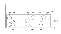
- FIG. 2 is a diagram illustrating a state in which the packaged medicine is transported.
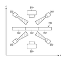
- FIG. 3 is a side view showing the arrangement of the light source and the camera.
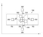
- FIG. 4 is a plan view showing the arrangement of the light source and the camera.
- FIG. 5 is a diagram illustrating the configuration of the processing unit.
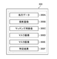
- FIG. 6 is a diagram illustrating information stored in the storage unit.
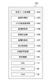
- FIG. 7 is a diagram illustrating the medicine specifying method according to the first embodiment.
- FIG. 8 is a diagram showing how to determine whether the tablet is a divided tablet.
- FIG. 9 is another diagram showing how to determine whether or not the tablet is a divided tablet.
- FIG. 10 is a diagram illustrating a state of template matching.
- FIG. 11 is a diagram showing a state of cutting out the half tablet area.
- FIG. 12 is a diagram showing how a region for template matching is enlarged.
- FIG. 13 is a diagram showing the extraction result of the medicine region image, the mask image, and the stamp.
- FIG. 14 is a diagram illustrating a manner of calculating a matching score.
- FIG. 15 is a diagram illustrating an example of a tablet.
- FIG. 16 is a diagram illustrating an example of display by the first display process.
- FIG. 17 is a diagram illustrating an example of display by the second display process.
- FIG. 18 is a diagram for explaining matching for an elliptical tablet.
- FIG. 19 is another diagram for explaining matching of an oval tablet.
- FIG. 20 is another diagram for explaining matching of an oval tablet.
- FIG. 21 is a diagram for describing calculation of a matching score for an elliptical tablet.
- FIG. 22 is a side view showing the arrangement of the light source and the camera when the medicine is identified.
- FIG. 23 is a plan view showing an arrangement of a light source and a camera when performing drug identification.
- FIG. 24 is a diagram illustrating a rotation angle of a rectangle circumscribing the divided tablet.
- FIG. 25 is a diagram illustrating a state where the circumscribed rectangle is displayed upright.
- FIG. 26 is a perspective view illustrating an example of a sheet in which tablets are stored (an undivided state).
- FIG. 27 is a front view illustrating an example (undivided state) of a sheet storing tablets.
- FIG. 28 is a diagram illustrating an example of a sheet in which tablets are stored (divided state).
- FIG. 29 is a diagram illustrating an example of the first display process.
- FIG. 30 is a diagram illustrating an example of the second display process
- FIG. 1 is a diagram illustrating a configuration of a tablet identifying device 10 (object matching device, tablet identifying device) according to the first embodiment of the present invention.
- the tablet specifying device 10 includes a processing unit 100, a storage unit 300, a display unit 400, an operation unit 500, and a transport mechanism 240.
- the processing unit 100 includes an illumination unit 200, a camera 210 (first image acquisition ), A camera 220 (first image acquisition unit), and a prescription reader 230.
- the cameras 210 and 220 are digital cameras. As shown in FIG. 2, the camera 210 is arranged vertically above the medicine bandage 700 (+ Z side in FIG. 3) in which the sachet 702 (medicine bag) is continuously formed, and vertically below the medicine bandage 700 ( The camera 220 is disposed on the ( ⁇ Z side in FIG. 3), and the tablet 800 (tablet, object) packaged in the packaging bag 702 is photographed from above and below (a plurality of different directions), and images are formed on the front surface and the back surface. (First captured image) is acquired. The sachet 702 (medical bandage 700) is conveyed by the conveying mechanism 240 in the + X direction of FIG.
- the plurality of light sources 202 illuminate the sachet 702 from four directions.
- the prescription reader 230 reads the prescription information. For example, information such as a patient's name, prescribed medicines and the quantity thereof is read from a prescription written on paper by OCR (Optical Character Recognition). When a barcode or the like indicating information on the prescribed medicine is recorded on the prescription, information on the prescribed medicine and the quantity thereof may be read from the barcode.
- a user such as a doctor or a pharmacist may read a prescription and input prescription information (prescription data) using an input device such as the keyboard 510 and / or the mouse 520 of the operation unit 500.
- the processing unit 100 specifies the medicine packaged in the packaging bag 702 based on the images captured by the cameras 210 and 220, the information read by the prescription reader 230, and the like. As shown in FIG. 5, the processing unit 100 includes a prescription data acquisition unit 100A (prescription data acquisition unit), an image acquisition unit 100B (image acquisition unit, first image acquisition unit), and a master image acquisition unit 100C (master image acquisition unit).
- prescription data acquisition unit 100A prescription data acquisition unit
- an image acquisition unit 100B image acquisition unit, first image acquisition unit
- master image acquisition unit 100C master image acquisition unit
- Second image acquisition unit tablet determination unit 100D (tablet determination unit, division determination unit), image generation unit 100E (image generation unit), tablet identification unit 100F (tablet identification unit), display control unit 100G (display control) ), A whole tablet specifying unit 100H (all tablet specifying unit), and a preprocessing unit 100I (preprocessing unit, collating unit).
- the processing unit 100 includes a CPU 110 (CPU: Central Processing Unit), a ROM 120 (ROM: Read Only Memory), and a RAM 130 (RAM: Random Access Memory).
- the function of the processing unit 100 described above can be realized using various processors.
- the various processors include, for example, a CPU (Central Processing Unit) that is a general-purpose processor that executes software (programs) to realize various functions.
- the various processors described above include a programmable logic device (GPU) that can change the circuit configuration after manufacturing such as a GPU (Graphics Processing Unit) or an FPGA (Field Programmable Gate Array) that is a processor specialized in image processing.
- Programmable Logic Device PLD
- the above-mentioned various processors also include a dedicated electric circuit which is a processor having a circuit configuration specifically designed to execute a specific process such as an ASIC (Application ⁇ Specific ⁇ Integrated ⁇ Circuit).
- ASIC Application ⁇ Specific ⁇ Integrated ⁇ Circuit
- each unit may be realized by one processor or may be realized by a plurality of same or different processors (for example, a plurality of FPGAs, a combination of a CPU and an FPGA, or a combination of a CPU and a GPU). Further, a plurality of functions may be realized by one processor. As an example in which a plurality of functions are configured by one processor, first, as represented by a computer, one processor is configured by a combination of one or more CPUs and software, and the processor functions as a plurality of functions. There is a form to realize. Second, as represented by a system-on-chip (SoC), there is a form in which a processor that realizes the functions of the entire system with one integrated circuit (IC) chip is used.
- SoC system-on-chip
- various functions are configured using one or more of the above-described various processors as a hardware structure.
- the hardware structure of these various processors is, more specifically, an electric circuit (circuitry) combining circuit elements such as semiconductor elements.
- These electric circuits may be electric circuits that realize the above-described functions by using a logical operation, a logical product, a logical negation, an exclusive logical sum, and a logical operation in which these are combined.
- the processor or the electric circuit executes the software (program)
- the processor (computer) readable code of the software to be executed is stored in a non-temporary recording medium such as a ROM 120 (ROM: Read Only Memory).
- the processor refers to the software.
- the software stored in the non-transitory recording medium includes a program for executing the object matching method according to the present invention and the tablet specifying method described later.
- the code may be recorded on a non-temporary recording medium such as a magneto-optical recording device or a semiconductor memory instead of the ROM.
- a RAM 130 Random Access Memory
- EEPROM Electrically Erasable and Programmable Read Only Memory
- the storage unit 300 includes a non-temporary recording medium such as a CD (Compact Disk), a DVD (Digital Versatile Disk), a hard disk (Hard Disk), various semiconductor memories, and a control unit thereof, and the information shown in FIG. It is memorized.
- the prescription data 300A is information on the prescription read by the prescription reader 230 or information input or edited by the user based on the prescription.
- the prescription data 300A may include, for example, inputting the name of a specific drug based on the general name of the drug described in the prescription, or changing the original drug and the generic drug mutually.
- the photographed image 300B (first photographed image) is an image of the medicine photographed by the cameras 210 and 220, and includes images of the front and back surfaces of the medicine. When a plurality of medicines (tablets) are included in the photographed image, an image obtained by extracting a region for a single medicine from the photographed image may be used as the photographed image 300B.
- the matching image 300C (first matching image based on the first captured image) is an image of a tablet determined to be a divided tablet, including a tablet region generated from the captured image, and is used as a master image. Used for template matching.
- Mask image 300D includes a first mask image that is a tablet region extraction mask image and a second mask image that is a stamp and / or print region extraction mask image. These mask images may be binarized.
- the master image 300E (second matching image based on the second captured image) is an image of the front and back surfaces of the tablet (object) in an undivided state, and is an image serving as a reference when performing template matching. is there.
- the specification result 300F is a specification result of the type and surface of the tablet indicated by the matching image.
- the display unit 400 includes a monitor 410 (display device), and can display input images, processing results, information stored in the storage unit 300, and the like.
- the operation unit 500 includes a keyboard 510 and a mouse 520 as an input device and / or a pointing device.
- the user can input an image capturing instruction, a tablet identification instruction, and a display mode (screen) via these devices and the screen of the monitor 410. It is possible to perform an operation necessary for executing the object matching method according to the present invention or the tablet specifying method described later, such as selection of the first display process or the second display process) (described later).
- the monitor 410 may be configured with a touch panel, and operations may be performed via the touch panel.
- the prescription data acquisition unit 100A inputs prescription information via the prescription reader 230 (step S100: prescription data acquisition step).
- the input prescription information may be obtained as it is as prescription data, or information input or edited by the user via the operation unit 500 based on the prescription may be obtained as prescription data.
- the prescription data acquisition unit 100A stores the drug characteristics (eg, tablet type, shape, color, and the like) visually recognized by the user, or the name and quantity of a drug described in a notebook such as a so-called “medicine notebook”.
- information such as a dosing method may be input as related information according to a user operation, and may be used in addition to or instead of the prescription data.
- the image acquisition unit 100B controls the cameras 210 and 220 to photograph the medicine (tablet) packaged in the packaging bag 702 from a plurality of different directions ( ⁇ Z directions in FIGS. 2 and 3; vertical vertical direction).
- a captured image (first captured image) is acquired (step S110: image acquisition step, first image acquisition step).
- the sachet 702 is illuminated by the illumination unit 200 and the light source 202.
- the master image acquisition unit 100C acquires a master image of the front and back surfaces of the tablet (object) in an undivided state based on the acquired prescription data (step S120: master image acquisition step, second image) Acquisition process).
- the master image acquisition unit 100C may acquire the master image 300E stored in the storage unit 300, or may acquire the master image from an external server, database, or the like via a communication line (not shown). Further, the master image acquisition unit 100C captures an image (second captured image) of the tablet (target object) in an undivided state via the camera 210, the camera 220, and the image capture unit 100B, and captures the captured image. May be performed to obtain a master image.
- the tablet determination unit 100D determines (determines) whether the tablet (target object) shown in the captured image (first captured image) is a divided tablet (whether or not the tablet is divided). (Step S130: tablet determination step, division determination step). This determination can be made, for example, by the following methods 1 and 2.
- the tablet determination unit 100D determines the tablets that are not specified as “all tablets” and the tablets that are determined to be “unknown” by these methods as “divided tablets”. Yes ". Note that, in the first embodiment, the tablet is an aspect of the “divideable medical article”.
- the all-tablet specifying unit 100H (division determination unit) specifies the type of undivided tablets (all tablets) based on the captured image and the master image. Specifically, all tablets are specified by template matching between the captured image and the master image.
- the template matching can be performed by a known method (for example, a method described in JP-A-2014-67342).
- the tablet determination unit 100D (division determination unit) can make a determination based on the symmetry (asymmetry) of the pixel distribution in the mask image as described below. All tablets are often symmetric in both the horizontal and vertical directions (when aligned horizontally or vertically), but split tablets are considered to be asymmetric as shown below.
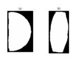
- FIG. 8 shows a case where a binary mask image of a tablet shown in a captured image is generated using a hierarchical network (for example, a neural network for area extraction; a first hierarchical network) constructed by machine learning, and the mask image is generated.
- a hierarchical network for example, a neural network for area extraction; a first hierarchical network
- FIG. 8A shows a portion (a) and FIG. 8B shows a portion (b) of a divided tablet (1/2 of all tablets), and FIG. 8B shows a standing tablet (a tablet whose cut surface is in contact with a mounting surface).
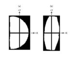
- FIG. 10 is a diagram illustrating a rectangle circumscribing a tablet area (an area having a pixel value of 255) of a binarized mask image. In this state, as shown in FIG.
- the rectangular area is divided into a plurality (for example, two in the horizontal direction and two in the vertical direction, for a total of four), and white pixels (pixels having a pixel value of 255) of each area are divided.
- white pixels pixels having a pixel value of 255
- the above determination can be made based on the pixel value distribution.
- a split tablet half tablet
- the + X side and the -X side are asymmetric
- the + Y side and the -Y side are symmetrical
- FIG. 9B the + X side and the ⁇ X side
- the + Y side and the ⁇ Y side are almost symmetric.
- the tablet determination unit 100D can determine a split tablet (half tablet) if asymmetric on the + X side and the ⁇ X side, and determine a standing tablet if it is symmetric (excluding those determined to be all tablets). That is, when the outer shape of the tablet (object) has a predetermined shape (has the above-mentioned symmetry), it is determined that the tablet is divided.
- the above-described region extraction neural network can be formed by machine learning (GAN: Generative Adversarial Networks) such as conditional GAN or the like in which a separately created mask image is given as teacher data.
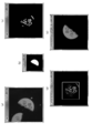
- Part (a) of FIG. 10 is an example of a photographed image showing a divided tablet, and a binary mask image is generated from such a photographed image using a neural network for area extraction (first hierarchical network).
- Part (b) of the figure the captured image is multiplied by the binarized mask image, and pre-processing (engraving extraction, binarization, inversion, etc.) is performed to generate a matching image (portion (c) in FIG. 3).
- a matching score is calculated while relatively rotating the matching image and the master image, a rotation angle at which the score is maximized is obtained (portion (d) in the figure), and the tablet area image is inverted by the rotation angle. Rotate to align the direction of printing or marking with the master image (portion (e) of FIG. 7; in the case of the second display process).
- the image generation unit 100E (first image acquisition unit) generates a matching image (first matching image) for the divided tablets included in the captured image (first captured image) (step S140: image generation) Step, first image acquisition step).
- the image generation unit 100E In order to identify the front and back surfaces of the tablet, the image generation unit 100E generates and associates a matching image for each of the images captured by the cameras 210 and 220 from above and below. Hereinafter, generation of the matching image will be described.
- the image generation unit 100E generates a mask image by using a region extraction neural network (first hierarchical network), and performs preprocessing such as binarization and shaping by closing on the generated mask image.
- a region extraction neural network first hierarchical network
- preprocessing such as binarization and shaping by closing on the generated mask image.
- the neural network for region extraction the one used in the determination of the divided tablet described above can be used.
- the image generation unit 100E multiplies the preprocessed mask image by the photographed image to extract the tablet region, and performs noise removal and the like.
- the image generating unit 100E obtains a rectangle including the tablet region (for example, a rectangle circumscribing the tablet region), and cuts out a range of the square including the rectangle from the captured image to use as a matching image.
- the rotation angle of the rectangle is calculated to be upright.
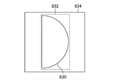
- FIG. 11 is a diagram illustrating an example of the relationship between the divided tablet region, the rectangle, and the matching image (the divided tablet region 830, the rectangle 8
- the pre-processing unit 100I (collating unit) performs an area enlarging process, a binarizing process, an image inverting process, a printing and / or engraving area (a partial area including identification information) on the matching image and / or the master image. ) Is performed as preprocessing (step S150: preprocessing step, collation step). It should be noted that whether or not to perform the binarization processing, the image inversion processing, the processing for extracting the print and / or engraving area, and the processing for enhancing the print and / or engraving (the processing for enhancing the identification information) depends on the matching image. It is preferable to align with the master image. Further, it is preferable that the size of the matching image and the size of the master image are made uniform by enlarging or reducing the image.
- the preprocessing unit 100I enlarges the area so that the matching image includes the circumscribed circle of the tablet area.
- the preprocessing unit 100I enlarges the area so that the matching image includes the circumscribed circle of the tablet area.
- the length of the side of the matching image 834 before the region enlargement shown in the portion (a) of FIG. 12 is “a”, as shown in the portion (b) of FIG.
- a part of the image may extend outside the matching image 834.
- the area can be enlarged to include the circumscribed circle by enlarging the area by 0.25a on both sides and setting the length of the side to “1.5a”.
- the matching image 836 shown in FIG. 12D is obtained.
- part (e) of FIG. 12 is a diagram illustrating an example (master image 838) of a master image on which preprocessing for engraved part extraction has been performed.
- the preprocessing unit 100I may cut out a range of a square in consideration of a margin area from the matching image 836 in the circumscribed circle 835, and enlarge or reduce the size of the square to match the size of the master image as a matching image.
- the margin area can be, for example, about (1/10) ⁇ a to (1/12) ⁇ a with respect to the circumscribed circle (“a” is the length of one side of the square including the above-described rotated rectangle).
- the margin area is secured as a wider area in consideration of the tilt error and the like.
- the preprocessing unit 100I may perform binarization processing, image inversion processing, and engraving extraction processing on the matching image in addition to or instead of the area expansion described above.
- the stamp extraction can be performed by multiplication with a mask image generated using a stamp extraction neural network (second hierarchical network).
- the tablet specifying unit 100F performs template matching using the matching image 836 after such preprocessing and the master image.
- the second hierarchical network can be configured by giving an image from which a print and / or a stamp is extracted as teacher data and performing machine learning.
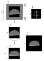
- FIG. 13 is a diagram illustrating an example of extraction results of a tablet region image, a mask image for region extraction and a stamp extraction, a stamp, and the like.
- the column denoted by reference numeral 810 indicates an image (front or back of a tablet) obtained by cutting out the above-described rectangle (corresponding to the rectangle 832 in FIG. 11) from the captured image, and the column denoted by reference numeral 812 corresponds to the column denoted by reference numeral 810. The opposite side of the image shown (back or front of tablet) is shown.
- the columns of reference numerals 814 and 816 indicate the binary mask images for engraving extraction (front or back surface; corresponding to the images of reference numerals 810 and 812), and the columns of reference numerals 818 and 820 indicate the binary values for extracting the tablet area.
- 3 shows a mask image (front or back surface; corresponding to the reference numerals 810 and 812).
- the mask image for extracting the stamp is smaller than the mask image for extracting the tablet area in order to eliminate the influence of the reflection of the side surface and the cross section caused by the tilt.
- the columns of reference numerals 822 and 824 show the results (front or back) of extracting the engraving from the images shown in the columns of reference numerals 810 and 812. In these images, the images in the same row are images for the same tablet.
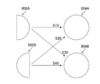
- FIG. 14 is a conceptual diagram showing how to calculate a matching score between a matching image for the front and back surfaces of a captured image and a master image for the front and back surfaces of a tablet.
- Images 802A and 802B show images of the divided tablet, one of which is a front surface and the other is a back surface.
- Master images 804A and 804B are master images for the front and back surfaces, respectively.
- the tablet specifying unit 100F calculates the matching scores S10 to S40 at each rotation angle.
- Matching scores S10 and S20 are matching scores for images 802A and 802B (matching images) and master image 804A (front surface), respectively, and matching scores S30 and S40 are for images 802A and 802B (matching images) and master, respectively. It is a matching score for the image 804B (back side).
- the matching score may be calculated while rotating the images for matching and the master image relatively little by little in a state where the centers of the images are matched, or (b) the rotation angle. May be created in advance, and each image may be moved to calculate a matching score.
- accurate matching can be performed by reducing the change in the rotation angle (for example, using 360 images whose rotation angles are different by 1 deg), but processing may require time. In this case, a small number of images with a large change in the rotation angle are created and rough matching is performed (for example, 36 images whose rotation angles are different by 10 deg are used).
- the matching can be performed using images with small changes (for example, using ten images having different rotation angles by 1 deg), so that the processing can be speeded up.
- the tablet specifying unit 100F calculates (correlation score value in template matching (standardized)) ⁇ (number of pixels of image indicating printing and / or engraving of matching image) ⁇ (printing and / or printing of master image) Alternatively, it is preferable to calculate the number of pixels of the image indicating the engraved portion) as a matching score and specify the type and face of the tablet based on the matching score.
- the “correlation score value (normalized)” is multiplied by “the number of pixels of the image showing the printing and / or engraving of the matching image” and “the number of pixels of the image showing the printing and / or engraving of the master image”.
- the “number of pixels of the image indicating the print and / or engraved portion” may be, for example, an image (print and / or print of the divided tablet) shown in the column of reference numerals 822 and 824 in FIG.
- the number of white pixels in an image showing an engraved portion) and the number of white pixels in the portion (e) of FIG. 12 (image showing a printed and / or engraved portion of a master image) in FIG. 12 can be used. Further, the number of pixels in the dividing line portion may be excluded when obtaining the “number of pixels of the image indicating the printing and / or engraved portion” for the master image.
- the specifying unit 100F compares the maximum values of the matching scores with respect to the individual master images, and can specify that “the matching image indicates the same tablet as the master image having the largest matching score”.
- the tablet specifying unit 100F specifies the angle at which the matching score becomes maximum as the rotation angle of the tablet.
- the tablet specifying unit 100F specifies the surface (front surface or back surface) of the tablet, for example, based on the following criteria.
- the image 802A indicates the surface and the image 802B Indicates the back surface.
- the tablet specifying unit 100F determines whether or not the processing has been completed for all the divided tablets (step S170), and repeats the processing from step S140 to S160 until the determination is affirmed. If the determination in step S170 is affirmative, the process for one sachet is ended and the process proceeds to step S180, and the process in all the sachets is completed (until the determination in step S180 is affirmative) in step S110. Steps S170 to S170 are repeated. If the determination in step S170 is affirmative, the process proceeds to step S190.
- the display control unit 100G determines the master image and the matching image specified to show the same tablet and the same surface as the master image (the first matching image).
- the monitor 410 displays the tablet (display image determined to show the same type of tablet (object)) (step S190: display control step).
- step S190 a first display process for aligning and displaying the direction of the string, which is a straight line portion of the divided tablet, or a second display process for aligning and displaying the printed and / or engraved direction of the divided tablet is performed.
- the display control unit 100G may perform any of the display processes according to the user's instruction, or may perform any of the display processes without depending on the user's instruction.
- a captured image and a tablet region image may be displayed instead of the matching image.
- an image that has not been subjected to preprocessing may be used, or an image that has been subjected to preprocessing may be used.
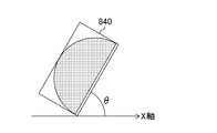
- the display control unit 100G can determine, for example, a side having a small curvature, a short side, a side close to the center of a circumscribed circle, or the like in the matching image or the mask image as a chord. In the calculation of the string direction, the display control unit 100G vertex coordinates the rectangle 840 (circumscribed rectangle) circumscribing the divided tablet (half tablet) as shown in FIG.
- the display control unit 100G rotates the circumscribed rectangle by (90 deg- ⁇ deg) to erect the circumscribed rectangle, and obtains an image in which the divided tablets are erect (either the rectangle 841 or the rectangle 842 in FIG. 25).
- the display control unit 100G examines the pixel distribution of the upright divided tablet, and specifies whether there are many bright pixels in the right half as shown by the rectangle 841 or many bright pixels as shown by the rectangle 842 (“determination of the divided tablet”). Can be specified based on the distribution of white pixels in the mask image as described in Method 2).
- the strings By rotating 90 degrees clockwise in the state of the rectangle 841 and 90 degrees counterclockwise in the state of the rectangle 842, the strings can be aligned in the horizontal direction.
- the strings When displaying the strings, the strings may be arranged not vertically but vertically or obliquely.
- the direction of the bow (the curved portion of the divided tablet) (an example of the direction of the outer shape of the object) may be displayed in addition to the direction of the string of each tablet (FIG. 16). See).
- ⁇ Second display processing> the printing and / or engraving (an example of the identification information attached to the target object) in the matching image is displayed in the same direction.
- the display control unit 100G can align the directions of printing and / or engraving by rotating the matching image backward by the rotation angle specified by the above-described processing.
- the target tablet is “Valsartan tablet 80 mg FFP” shown in FIG. Part (a) of FIG. 15 is a front view (front surface) of the tablet, in which printing and dividing lines are given. Part (b) of the figure is a side view. The relationship between the dividing line and the printing direction differs depending on the tablet, and the dividing line may be provided horizontally or vertically with respect to the printing.
- the portions (c) and (d) of FIG. 15 are rear views (back). Printing is performed on the back surface as well as the front surface, but the printing direction is not constant between the front surface and the back surface.
- the back surface may be as shown in FIG. 15C (the printing direction is the same as the front surface) with respect to the front surface shown in FIG. 15A, or as shown in FIG. 15D. (The surface and the printing direction are different).
- FIG. 16 shows an example of the first display process for the tablet described above.
- Part (a) of the drawing shows the display of the front side of the master image (the area on the left side of the white line) and the front side of the matching image (the area on the right side of the white line)
- part (b) of the drawing shows the back side of the master image. (Area on the left side of the white line) and the back side of the matching image (Area on the right side of the white line).
- the images present at the same position in the portion (a) and the portion (b) indicate the same tablet.
- FIG. 17 shows an example of the second display process.
- Part (a) of the figure shows the front surface of the master image (the area on the left side of the white line) and the surface of the matching image (the area on the right side of the white line), and part (b) of the figure shows the back surface of the master image. (Area on the left side of the white line) and the back side of the matching image (Area on the right side of the white line). Also in FIG. 17, the images present at the same position in the portion (a) and the portion (b) indicate the same tablet.
- the display control unit 100G selects a matching image (first matching image) for the front surface and / or the back surface of the tablet (object) and displays the selected image on the monitor 410 ( Display device). Only the front image, the back image, or both images may be displayed. Further, the master image may be displayed together, or the display may be omitted.
- the divided tablets can be matched with good accuracy, and the matching result can be easily confirmed by the first and second display processes.
- FIG. 18 is an example of a master image of an elliptical tablet.
- FIG. 18A shows the surface of the tablet. On the left and right sides of the surface, "A" and “B” are marked (or printed), respectively.
- the portion (b) of the figure shows the back surface of the tablet. On the left and right sides of the back surface, “C” and “D” are marked (or printed), respectively.
- the tablet is scored in the center.
- FIG. 19 shows a state in which the tablet of FIG. 18 is divided.
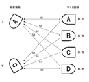
- FIG. 21 is a diagram showing a state of matching of the oval tablets shown in FIGS.
- “upper” is, for example, an image photographed from above by the camera 210
- “lower” is, for example, an image photographed from below by the camera 220. Any one of A, B, C, and D is engraved on the photographed image, and the engraving of the photographed image shown in FIG. 21 is an example.
- the tablet specifying unit 100F calculates the following matching scores S1 to S8 (corresponding to step S160 in FIG. 7, a tablet specifying step).
- the “matching score S1” may be described as “S1” (the same applies to the matching scores S2 to S8).
- Matching score S1 Matching score for photographed image (photographed from above) and master image (left side of surface)
- Matching score S2 Matching score for photographed image (photographed from above) and master image (right side of surface)
- Matching score S3 Matching score for photographed image (photographed from above) and master image (left side on back side)
- Matching score S4 Matching score for photographed image (photographed from above) and master image (right side on back side)
- Matching score S5 photographed image (lower side)
- Matching score S6 Matching score for master image (photographed from below) and master image (photographed from bottom)
- Matching score S7 Matching score for master image (photographed from below)
- Matching score S8 Matching score between photographed image (photographed from below) and master image (right side on the back side)
- Matching score S1 is obtained by comparing the photographed image (photographed from above) with the master image (front side).
- (S1, S7) means that "an image photographed from above indicates the left side of the front surface, and an image photographed from below indicates the left side of the rear surface".
- the tablet specifying unit 100F specifies the surface of the elliptical divided tablet by the following first and second methods. Thereby, the elliptical divided tablets can be matched with good accuracy to specify the tablet surface. It is assumed that the type of tablet is specified separately (including the case where there is only one type of divided tablet in the prescription data or the photographed image of the sachet).
- the maximum score among T8 As a result, when the maximum score is any of the scores T1, T2, T7, and T8, the tablet specifying unit 100F specifies that the image taken from above is the front side and the image taken from below is the back side. On the other hand, when the maximum score is any of the scores T3, T4, T5, and T6, the tablet specifying unit 100F specifies that the image taken from above is the back side and the image taken from below is the front side.
- the display control unit 100G performs the first display processing for aligning and displaying the direction of the chord, which is the linear portion of the divided tablet, or aligning the printing and / or engraving directions of the divided tablet.
- a second display process for displaying is performed, and the result can be displayed on the monitor 410 (display device) as shown in FIGS. Thereby, the matching result can be easily confirmed.
- the object collation device tablette identification device
- the tablet 800 is put in a container 710 such as a petri dish instead of a sachet, and imaging is performed.
- FIG. 23 is a plan view of the state shown in FIG.
- Other configurations in the case of performing the discrimination are the same as those of the above-described tablet identification device 10.
- the tablet identification processing can be performed in the same manner as in the above-described embodiment, but when discriminating the bring-drug, the prescription may not be confirmed in some cases.
- the prescription data acquisition unit 100A determines the characteristics (for example, the type, shape, and color of the tablet) of the medicine visually recognized or the like, or the medicine name and quantity described in a notebook such as a so-called “medicine notebook”.
- Information such as a dosing method may be input as related information according to a user's operation and used instead of prescription data.
- the divided tablet (object that is a divisible medical article) with good accuracy can be obtained by the object collation device (tablet identification device) and the object collation method (tablet identification method) of the present invention. Matching can be performed, and the matching result can be easily confirmed by the first and second display processes.
- a so-called PTP packaging sheet (PTP: press through pack) is a sheet-like package in which tablets and capsules are housed between plastic and aluminum foil, and are formed three-dimensionally according to the shape of tablets or capsule-type drugs. Pressing hard on the plastic part breaks the aluminum foil, and the tablets inside can be taken out one by one.
- a PTP packaging sheet is provided with a plurality of perforations, and can be divided along the perforations. That is, a PTP packaging sheet is another example of a divisible medical article.
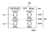
- FIG. 26 is a perspective view of a sheet 900 (undivided state), which is a PTP packaging sheet containing tablets, as viewed from the front side
- FIG. 27 is a front view.
- the sheet 900 has the name of the drug, the amount of the active ingredient, and the like printed on the end portion 902 and the main body portion 904 by characters and numbers (an example of identification information; similar information is also printed on the back surface). Is cut (divided) along the perforations 904B to adjust the number of tablet portions 904A and obtain a required number of tablets 910. Note that the identification information in FIGS. 26 and 27 is provided for convenience of description, and does not accurately reproduce the display of an actual product.
- FIG. 26 and 27 is provided for convenience of description, and does not accurately reproduce the display of an actual product.
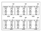
- FIG. 28 is a diagram illustrating an example of the sheet 900 in a state where a part of the main body 904 is cut off. This is the case when the tablet is divided and provided to the patient according to the prescription, or when the portion from which the tablet is taken out is cut off.
- Such a sheet 900 can be collated in the same manner as in the case of the tablet described above. Specifically, as shown in FIGS. 26 and 27, the front and back surfaces of the sheet 900 (object) that is not divided by the master image acquisition unit 100C and the camera 210, the camera 220, the image acquisition unit 100B, and the master image. (A second matching image based on the second captured image) is acquired, and the front and back surfaces of the sheet 900 to be compared (undivided or divided) are determined based on the first captured image. The first matching image is acquired. Subsequent processing can be executed according to the flowchart shown in FIG. 7, similarly to the case of tablets.
- FIG. 29 is an example showing a state where the first display processing is performed on the divided sheet 900.
- the direction of the outer shape of the sheet 900 is aligned by aligning the direction of the perforation 904B, which is the dividing line (and the direction of the object with respect to the dividing line).
- FIG. 29 shows a display example of the front surface, the same can be displayed on the back surface (see the example of FIG. 16).
- FIG. 30 is an example showing a state where the second display processing is performed on the divided sheet 900.
- the sheet 900 is not always separated at the perforation 904B, but may be separated by scissors or the like in a direction orthogonal to the perforation 904B.
- the shape of the sheet 900 after division is the same. Not necessarily. In such a case, it is possible to perform a second display process of aligning and displaying the identification information (printing such as the name of the medicine in this case) attached to the sheet 900.
- FIG. 30 shows an example of display on the front surface, the same can be displayed on the back surface (see the example of FIG. 17).
- the case of the package (PTP sheet) containing tablets has been described above with reference to FIGS. 26 to 30, but the same applies to the case of sheets containing capsule-type drugs, and the results are compared with the first and second cases. It can be displayed by the second display processing. Note that the collation and display processing can be similarly performed on a package of a type in which a bag-shaped storage unit for individually storing tablets is continuously formed in a sheet shape.
- the package In the case of a package containing a tablet or a package containing a capsule-type drug, the package can be matched with good accuracy as in the case of the tablet, and the matching result can be obtained by the first and second display processes. It can be easily confirmed.
- the tablet identification device according to Supplementary Note 1, an image acquisition unit that acquires a photographed image of the tablet taken from a plurality of different directions, a master image acquisition unit that acquires a master image of the front and back surfaces of the undivided tablet, A tablet determining unit that determines whether the tablet shown in the captured image is a divided tablet; and generating a matching image including a tablet region from the captured image of the tablet determined to be the divided tablet.
- the first display process of displaying the matching result with respect to the divided tablet with the direction of the string which is the straight line portion of the divided tablet, aligned, or the display of the divided tablet with the printed and / or engraved direction aligned. Since the display is performed by the display processing of No. 2, the user can easily grasp the identification result (matching result) of the type and surface of the tablet visually.
- template matching is performed using a master image of a tablet that has not been divided, so that the possibility of erroneous matching due to matching of a small portion of the image is reduced, and accurate matching is achieved. It can be carried out. As described above, according to the configuration of Appendix 1, the divided tablets can be matched with good accuracy, and the matching result can be easily confirmed.
- the image acquisition unit acquires images captured from a plurality of opposing directions. It is further preferable to obtain images obtained by photographing the front and back surfaces of the tablet, such as in the vertical direction. Further, the master image may be obtained based on prescription data (information of a medicine described in a prescription and information input by a doctor, a pharmacist, or the like based on the information). Note that “specification” of a tablet can be performed in drug inspection, identification of brought-in drugs, and the like.
- the tablet determination unit may generate a mask image including the tablet region from the captured image and may perform a process based on a distribution of pixel values in the mask image. Make a decision.
- An undivided tablet generally has a symmetrical shape such as a circular shape or an elliptical shape, but the asymmetrical direction is generated by the division. Therefore, in the configuration of Supplementary Note 4, it is determined whether or not the tablet is a divided tablet based on the distribution (for example, asymmetry) of the pixel values in the mask image.
- an unnecessary portion such as noise is removed from the captured image, and an image including the tablet region can be used as a mask image, and may be binarized. Further, the range of the mask image can be, for example, a rectangle circumscribing the tablet region, but is not limited to such an embodiment.
- a standing tablet (a state in which a divided surface or a cut surface is in contact with a tablet mounting surface; so-called “standing tablet”) can also be determined based on a distribution of pixel values.
- the tablet determination unit In the tablet specifying device according to Supplementary Note 5, in the configuration of Supplementary Note 4, the tablet determination unit generates a mask image using the first hierarchical network constructed by machine learning.
- the first hierarchical network can be a neural network.
- a CNN Convolutional Neural Network
- the tablet determination unit generates a mask image using the first hierarchical network constructed by machine learning.
- the first hierarchical network can be a neural network.
- a CNN Convolutional Neural Network
- the image generating unit may generate a matching image by multiplying a pixel value of the captured image by a pixel value of the mask image for each pixel.
- the configuration of Supplementary Note 6 defines a specific mode of the matching image generation process, and can generate a matching image from which an unnecessary portion is removed by multiplication with a mask image.
- the tablet identifying device according to Supplementary Note 7, wherein in any one of the configurations of Supplementary Notes 1 to 6, the area enlargement processing, the binarization processing, the image inversion processing, the printing and / or the engraving are performed on the matching image and / or the master image.
- the tablet specifying unit further includes a preprocessing unit that performs at least one of a process of extracting a region, a process of emphasizing printing and / or engraving as a preprocess, and the tablet specifying unit includes a preprocessed matching image and / or a master image. Perform template matching using the image. With the configuration of Appendix 7, matching can be performed more accurately by the preprocessing described above.
- pre-processing may determine the type and / or degree of the processing to be performed according to the user's instruction, or may be determined by the tablet specifying device without the user's instruction. It should be noted that whether or not to perform the binarization processing, the image inversion processing, the processing of extracting the printing and / or engraving area, and the processing of enhancing the printing and / or engraving as preprocessing is determined by the matching image and the master image. It is preferable to align them.
- the pre-processing unit performs a process of extracting a print and / or an inscription by using a second hierarchical network constructed by machine learning.
- the second hierarchical network can be a neural network. For example, using a CNN (Convolutional Neural Network) or the like, an image from which a print and / or an inscription has been extracted is given as teacher data to perform deep learning or the like. It can be configured by performing machine learning.
- CNN Convolutional Neural Network
- the tablet specifying device is the tablet specifying device according to any one of Supplementary Notes 1 to 8, wherein the tablet specifying unit calculates a matching score while relatively rotating the matching image and the master image, and generates a matching score. Specify based on.
- the matching score is calculated for the matching image in each of the plurality of directions and the front surface and the back surface of the master image, and the type and surface of the tablet can be specified based on the calculation result.
- the image may be rotated with the center of the circumscribed circle of the tablet area in the matching image and the center of the master image being matched, or the matching may be performed while moving the pre-rotated image. Further, in the matching, there may be a relative movement (parallel movement) of the image.
- the tablet identifying device according to Supplementary Note 10 is configured as described in Supplementary Note 9, wherein the display control unit calculates a rotation angle at which the matching score is maximized with respect to the specified surface in the second display process, and converts the matching image into an angle. And the direction of printing and / or engraving on the matching image is aligned with the master image.
- the configuration of Supplementary Note 10 specifically defines a process of aligning the printing and / or engraving directions in the matching image with the master image in the second display process.
- the tablet specifying method includes: an image obtaining step of obtaining captured images of the tablet taken from a plurality of different directions; a master image obtaining step of obtaining a master image of the front and back surfaces of the undivided tablet; A tablet determining step of determining whether the tablet shown in the image is a divided tablet, and an image for generating a matching image including a tablet region from a captured image of the tablet determined to be a divided tablet A generating step, a tablet specifying step of specifying a tablet type and a surface indicated by the matching image by template matching of the matching image and the master image, and a master image and a tablet identical to the master image based on a specific result.
- a display control step of displaying a matching image specified to indicate the same surface on a display device, wherein a straight line portion of the divided tablet A display control step of performing a second display process for displaying a first display processing, or printing of the divided tablets and / or align the orientation of the marking to be displayed by aligning the strings orientation, the that.
- the divided tablets can be matched with good accuracy, and the matching result can be easily confirmed.
- the tablet identifying method according to Supplementary Note 12 may further include configurations similar to Supplementary Notes 2 to 11.
- a program that causes a tablet specifying device or a computer to execute the tablet specifying method according to any of the embodiments, and a non-transitory recording medium that records a computer-readable code of the program can also be included as embodiments of the present invention.
- Tablet specifying device 100 Processing unit 100A Prescription data obtaining unit 100B Image obtaining unit 100C Master image obtaining unit 100D Tablet determining unit 100E Image generating unit 100F Tablet specifying unit 100G Display control unit 100H All tablet specifying unit 100I Preprocessing unit 110 CPU 120 ROM 130 RAM 200 illumination unit 202 light source 210 camera 220 camera 230 prescription reader 240 transport mechanism 300 storage unit 300A prescription data 300B photographed image 300C matching image 300D mask image 300E master image 300F specification result 400 display unit 410 monitor 500 operation unit 510 keyboard 520 mouse 700 Medicine bandage 702 packaging bag 710 container 800 tablet 802A image 802B image 804A master image 804B master image 830 divided tablet region 832 rectangle 834 matching image 835 circumscribed circle 836 matching image 838 master image 840 rectangle 841 rectangle 842 rectangle 900 sheet 902 end Part 904 Body part 904A Tablet part 904B Perforation 910 Tablet 1001 Imaging optical axis ⁇ Rotation angle S1 Matching score S2 Matching score S3 Matching score S4 Match
Abstract
The objective of the present invention to provide an object comparison device and an object comparison method with which images of dividable medicinal goods can be matched with good precision and with which the matching result can be easily verified. When an object is determined to have been divided, the object comparison device according to a first aspect of the present invention compares a first image for matching to an image for matching of the object in a non-divided state (second image for matching), and thus is capable of matching images of dividable medicinal goods with excellent accuracy, without the matching target region becoming small. In addition, since first and second display processing are conducted for a display image determined to picture an object of the same type, the matching result can be confirmed readily.
Description
本発明は分割可能な医療用物品の画像をマッチングする対象物照合装置及び対象物照合方法に関する。
The present invention relates to an object collation device and an object collation method for matching images of a divisible medical article.
病院施設、薬局等では、薬剤の監査や持参薬の鑑別が行われる。これらを目視で行うと薬剤師等の作業負担が大きいため、監査あるいは鑑別を支援する技術が開発されている。監査や鑑別を行う場合、処方内容等の条件によっては錠剤が分割される場合があり、そのような分割された錠剤(異形錠錠剤)に対する監査を行うシステムも知られている。
At hospital facilities, pharmacies, etc., drug audits and identification of brought drugs are performed. If these operations are performed visually, the burden on the pharmacist or the like is large, and techniques for supporting auditing or discrimination have been developed. When performing inspection or discrimination, tablets may be divided depending on conditions such as prescription content, and a system for performing inspection on such divided tablets (deformed tablets) is also known.
例えば特許文献1では、異形錠錠剤の形状パターンである異形錠錠剤パターンと薬包帯画像とをパターンマッチングさせることにより異形錠錠剤の個数を監査することが記載されている。
For example, Patent Document 1 describes that the number of deformed tablet tablets is inspected by pattern-matching the deformed tablet pattern, which is the shape pattern of the deformed tablet, with a medicine bandage image.
錠剤を分割すると、印字や刻印等、錠剤に付された識別情報が途切れる場合がある。また、錠剤を撮影した画像における印字、刻印等の向きは不規則であり、撮影した画像やマッチングに用いた画像をそのまま表示したのではユーザにとって見づらく、確認が困難である。しかしながら上述した特許文献1では、異形錠錠剤(分割錠剤)の個数をカウントしているだけでこれらの問題を考慮しておらず、監査結果を確認することが困難であった。また、特許文献1では、標準形状錠剤パターン(分割していない錠剤のパターン)を異形錠錠剤の分割数で分割することにより異形錠錠剤パターンを生成し、異形錠錠剤の撮影画像と分割した状態の標準形状錠剤パターンとをマッチングしているが、分割した状態のマスタ画像を用いてマッチングを行うとマッチング対象の領域が狭くなり、異なる錠剤が僅かに一致しただけでも「同一の錠剤である」と誤って判断される可能性がある。さらに、特許文献1では錠剤の分割以外については考慮されていない。
分割 When a tablet is divided, the identification information such as printing and stamping may be interrupted. In addition, the orientation of printing, engraving, and the like in an image obtained by photographing a tablet is irregular, and if the photographed image or the image used for matching is displayed as it is, it is difficult for the user to see and confirm it. However, in Patent Document 1 described above, these problems are not taken into account simply because the number of deformed tablets (divided tablets) is counted, and it is difficult to confirm the inspection results. In Patent Document 1, a deformed tablet pattern is generated by dividing a standard shaped tablet pattern (pattern of an undivided tablet) by the number of divided deformed tablets, and is divided into a photographed image of the deformed tablet. However, if the matching is performed using the master image in the divided state, the area to be matched becomes narrower, and even if the different tablets slightly match, "the same tablet" May be erroneously determined. Furthermore, Patent Literature 1 does not consider anything other than tablet division.
このように、従来の技術では分割可能な医療用物品の画像のマッチング精度が低く、またマッチング結果の確認が困難であった。
As described above, in the related art, the matching accuracy of the image of the medical article that can be divided is low, and it is difficult to confirm the matching result.
本発明はこのような事情に鑑みてなされたもので、分割可能な医療用物品の画像を良好な精度でマッチングでき、またマッチング結果を容易に確認できる対象物照合装置及び対象物照合方法を提供することを目的とする。
The present invention has been made in view of such circumstances, and provides an object matching apparatus and an object matching method that can match images of a divisible medical article with good accuracy and that can easily confirm a matching result. The purpose is to do.
上述した目的を達成するため、本発明の第1の態様に係る対象物照合装置は、分割可能な医療用物品である対象物についての第1の撮影画像に基づく第1のマッチング用画像を取得する第1の画像取得部と、分割されていない状態の対象物についての第2の撮影画像に基づく第2のマッチング用画像を取得する第2の画像取得部と、第1の撮影画像に映っている対象物が分割されているか否かを判定する分割判定部と、対象物が分割されていると判定された場合に、第1のマッチング用画像と第2のマッチング用画像との照合を行う照合部と、照合の結果に基づいて第1のマッチング用画像のうち同一種類の対象物が映っていると判断された表示用画像を表示装置に表示させる表示制御部であって、対象物の外形の向きを揃えて表示させる第1の表示処理、または対象物に付された識別情報の向きを揃えて表示させる第2の表示処理を行う表示制御部と、を備える。
In order to achieve the above-described object, an object collation device according to a first aspect of the present invention acquires a first matching image based on a first captured image of an object that is a divisible medical article. A first image acquisition unit that performs a second matching image based on a second captured image of an object that is not divided, and a second image acquisition unit that acquires a second matching image. A division determining unit that determines whether or not the target object is divided, and, when it is determined that the target object is divided, performs collation between the first matching image and the second matching image. A collating unit for performing, and a display control unit for causing a display device to display a display image determined to show the same type of target object among the first matching images based on a result of the collation, Display the outline of the Comprising first display processing, or a display control unit that performs second display processing of displaying align the orientation of the identification information attached to the object, the.
第1の態様では、対象物が分割されていると判定された場合に、第1のマッチング用画像と、分割されていない状態の対象物についてのマッチング用画像(第2のマッチング画像)とを照合するので、上述した特許文献のようにマッチング対象の領域が狭くなることがなく、分割可能な医療用物品の画像を良好な精度でマッチングすることができる。また、同一種類の対象物が映っていると判断された表示用画像について第1,第2の表示処理を行うので、マッチング結果を容易に確認することができる。なお、第1,第2のマッチング用画像は第1,第2の撮影画像をそのまま用いてもよいし、第1,第2の撮影画像に対し画像処理(例えば、拡大、縮小、回転、領域抽出、領域強調)を施した画像を用いてもよい。なお、「分割可能な医療用物品」は物品が分割可能であればよく、物品それ自体が使用されるか否かは問わない(例えば、錠剤等の包装体には分割可能なタイプが存在するが、包装体それ自体が使用されるものではなく、使用されるのは錠剤である)。
In the first aspect, when it is determined that the target object is divided, the first matching image and the matching image (second matching image) of the undivided target object are generated. Since the collation is performed, the matching target area is not narrowed unlike the above-described patent document, and the images of the divisible medical articles can be matched with good accuracy. In addition, since the first and second display processes are performed on the display image determined to include the same type of target, the matching result can be easily confirmed. As the first and second matching images, the first and second captured images may be used as they are, or image processing (for example, enlargement, reduction, rotation, area (Extraction, region emphasis) may be used. The “dividable medical article” is not particularly limited as long as the article can be divided, and it does not matter whether the article itself is used (for example, there is a dividable type in a package such as a tablet). However, the package itself is not used, but a tablet is used).
第2の態様に係る対象物照合装置は第1の態様において、第1の画像取得部は対象物の表面及び裏面について第1のマッチング用画像を取得し、第2の画像取得部は分割されていない状態の対象物の表面及び裏面について第2のマッチング用画像を取得し、照合部は、対象物の表面及び裏面について照合を行い、表示制御部は、対象物の表面及び/または裏面についての第1のマッチング用画像を選択して表示装置に表示させる。
In the object collation device according to the second aspect, in the first aspect, the first image acquisition unit acquires the first matching image for the front surface and the back surface of the object, and the second image acquisition unit is divided. The second matching image is obtained for the front and back surfaces of the object not in the state, and the matching unit performs matching for the front and back surfaces of the object, and the display control unit performs the matching for the front and / or back surface of the object. Is selected and displayed on the display device.
第3の態様に係る対象物照合装置は第1または第2の態様において、表示制御部は、第1の表示処理において、対象物の分割により生じる分割線の向きを揃えることにより外形の向きを揃える。分割線の例としては円形の対象物を分割した際に生じる直線を挙げることができるがこれに限定されるものではない。なお、第1,第2の表示処理の際には、分割線の向きを揃えることに加えて、分割線に対する対象物の位置を揃える(例えば、対象物が分割線に対し上下左右方向のいずれかに位置させて揃える)ことが好ましい。
In the object collation device according to the third aspect, in the first or second aspect, the display control unit may adjust the shape of the outer shape by aligning the direction of a dividing line generated by dividing the object in the first display processing. Align. An example of the dividing line includes a straight line generated when a circular object is divided, but is not limited thereto. In the first and second display processes, in addition to aligning the direction of the dividing line, the position of the object with respect to the dividing line is aligned (for example, the object is positioned in any of the vertical and horizontal directions with respect to the dividing line). It is preferable to align them with each other).
第4の態様に係る対象物照合装置は第1から第3の態様のいずれか1つにおいて、照合部は対象物の外形及び/または識別情報に基づいて照合を行う。
In the object collation device according to the fourth aspect, in any one of the first to third aspects, the collation unit performs collation based on the outer shape and / or identification information of the object.
第5の態様に係る対象物照合装置は第1から第4の態様のいずれか1つにおいて、照合部は、第1のマッチング用画像のうち対象物及び/または識別情報を含む一部の領域を抽出し、一部の領域について照合を行う。
In the object matching device according to the fifth aspect, in any one of the first to fourth aspects, the matching unit may include a part of the first matching image that includes the object and / or identification information. Is extracted, and collation is performed for some regions.
第6の態様に係る対象物照合装置は第1から第5の態様のいずれか1つにおいて、分割判定部は、対象物の外形があらかじめ規定された形状である場合に対象物が分割されていると判定する。例えば、撮影画像における対象物を示す画素の分布に基づいて判定を行うことができる。なお、「あらかじめ規定された形状」として例えば半円形状、半楕円形状、縦横比が規定範囲の矩形を挙げることができるが、これらの例に限定されるものではない。
In the object collation device according to the sixth aspect, in any one of the first to fifth aspects, the division determination unit may be configured to divide the object when the external shape of the object is a predetermined shape. It is determined that there is. For example, the determination can be made based on the distribution of pixels indicating the target in the captured image. The “predetermined shape” includes, for example, a semicircular shape, a semielliptical shape, and a rectangle having an aspect ratio in a specified range, but is not limited to these examples.
第7の態様に係る対象物照合装置は第1から第6の態様のいずれか1つにおいて、照合部は、第1のマッチング用画像及び/または第2のマッチング用画像として識別情報を強調する処理を施した画像を用いて照合を行う。第7の態様によれば、良好な精度でマッチングを行うことができる。
In the object matching device according to the seventh aspect, in any one of the first to sixth aspects, the matching unit emphasizes the identification information as the first matching image and / or the second matching image. Matching is performed using the processed image. According to the seventh aspect, matching can be performed with good accuracy.
第8の態様に係る対象物照合装置は第1から第7の態様のいずれか1つにおいて、医療用物品は錠剤、錠剤が収納された包装体、カプセル型薬剤が収納された包装体のいずれかである。錠剤の形状は特に限定されない。また、包装体は錠剤あるいはカプセル型薬剤が一錠ずつ、あるいは1カプセルずつ取り出せるように収納されたシート状の包装体であってもよい。
An object collation device according to an eighth aspect is the object according to any one of the first to seventh aspects, wherein the medical article is any one of a tablet, a package containing a tablet, and a package containing a capsule-type drug. Is. The shape of the tablet is not particularly limited. Further, the package may be a sheet-like package in which tablets or capsule-type medicines are stored so as to be taken out one tablet at a time or one capsule at a time.
第9の態様に係る対象物照合装置は第1から第8の態様のいずれか1つにおいて、識別情報は対象物に付された印字及び/または刻印を含む。印字、刻印は文字、数字、記号、図形及びこれらの組み合わせにより行うことができ、色彩が付されていてもよい。
In the object collation device according to the ninth aspect, in any one of the first to eighth aspects, the identification information includes a print and / or a mark imprinted on the object. Printing and engraving can be performed using letters, numbers, symbols, figures, and combinations thereof, and may be colored.
上述した目的を達成するため、本発明の第10の態様に係る対象物照合方法は分割可能な医療用物品である対象物についての第1の撮影画像に基づく第1のマッチング用画像を取得する第1の画像取得工程と、分割されていない状態の対象物についての第2の撮影画像に基づく第2のマッチング用画像を取得する第2の画像取得工程と、第1の撮影画像に映っている対象物が分割されているか否かを判定する分割判定工程と、対象物が分割されていると判定された場合に、第1のマッチング用画像と第2のマッチング用画像との照合を行う照合工程と、照合の結果に基づいて第1のマッチング用画像のうち同一種類の対象物が映っていると判断された表示用画像を表示装置に表示させる表示制御工程であって、対象物の外形の向きを揃えて表示させる第1の表示処理、または対象物に付された識別情報の向きを揃えて表示させる第2の表示処理を行う表示制御工程と、を備える。
In order to achieve the above object, the object matching method according to the tenth aspect of the present invention acquires a first matching image based on a first captured image of an object that is a divisible medical article. A first image acquiring step, a second image acquiring step of acquiring a second matching image based on a second photographed image of the object which is not divided, and a first image photographed image. A division determining step of determining whether the target object is divided or not, and collating the first matching image and the second matching image when the target object is determined to be divided. A collation step, and a display control step of displaying, on a display device, a display image determined to show the same type of target object among the first matching images based on a result of the collation. Align the outer shape And a display control step of the first display processing, or the second display processing of displaying align the orientation of the identification information attached to the object performs that shown.
第10の態様によれば、第1の態様と同様に分割可能な医療用物品の画像を良好な精度でマッチングすることができる。また、マッチング結果を容易に確認することができる。
According to the tenth aspect, similarly to the first aspect, the images of the divisible medical articles can be matched with good accuracy. Further, the matching result can be easily confirmed.
なお、第10の態様に係る対象物照合方法に対し、第2から第9の態様と同様の構成をさらに含めてもよい。また、これら態様の対象物照合方法を対象物照合装置あるいはコンピュータに実行させるプログラム、及びそのプログラムのコンピュータ読み取り可能なコードを記録した非一時的記録媒体も、本発明の態様として挙げることができる。
Note that the object matching method according to the tenth aspect may further include the same configuration as the second to ninth aspects. In addition, a program for causing an object collation apparatus or a computer to execute the object collation method according to these aspects, and a non-transitory recording medium that records a computer-readable code of the program are also examples of the present invention.
以上説明したように、本発明の対象物照合装置及び対象物照合方法によれば、分割可能な医療用物品の画像を良好な精度でマッチングでき、またマッチング結果を容易に確認することができる。
As described above, according to the object matching device and the object matching method of the present invention, the images of the divisible medical articles can be matched with good accuracy, and the matching result can be easily confirmed.
以下、添付図面を参照しつつ、本発明に係る対象物照合装置及び対象物照合方法の実施形態について詳細に説明する。
Hereinafter, an embodiment of an object matching device and an object matching method according to the present invention will be described in detail with reference to the accompanying drawings.
<第1の実施形態>
図1は、本発明の第1の実施形態に係る錠剤特定装置10(対象物照合装置、錠剤特定装置)の構成を示す図である。錠剤特定装置10は処理部100と、記憶部300と、表示部400と、操作部500と、搬送機構240と、を備え、処理部100には照明部200,カメラ210(第1の画像取得部),カメラ220(第1の画像取得部),及び処方箋リーダ230が接続されている。 <First embodiment>
FIG. 1 is a diagram illustrating a configuration of a tablet identifying device 10 (object matching device, tablet identifying device) according to the first embodiment of the present invention. Thetablet specifying device 10 includes a processing unit 100, a storage unit 300, a display unit 400, an operation unit 500, and a transport mechanism 240. The processing unit 100 includes an illumination unit 200, a camera 210 (first image acquisition ), A camera 220 (first image acquisition unit), and a prescription reader 230.
図1は、本発明の第1の実施形態に係る錠剤特定装置10(対象物照合装置、錠剤特定装置)の構成を示す図である。錠剤特定装置10は処理部100と、記憶部300と、表示部400と、操作部500と、搬送機構240と、を備え、処理部100には照明部200,カメラ210(第1の画像取得部),カメラ220(第1の画像取得部),及び処方箋リーダ230が接続されている。 <First embodiment>
FIG. 1 is a diagram illustrating a configuration of a tablet identifying device 10 (object matching device, tablet identifying device) according to the first embodiment of the present invention. The
カメラ210及びカメラ220はデジタルカメラにより構成される。図2に示すように、分包袋702(薬包)が連続して構成される薬包帯700の鉛直上側(図3の+Z側)にカメラ210が配置され、薬包帯700の鉛直下側(図3の-Z側)にカメラ220が配置されて、分包袋702に分包された錠剤800(錠剤、対象物)を上下(複数の異なる方向)から撮影して、表面及び裏面について画像(第1の撮影画像)を取得する。分包袋702(薬包帯700)は搬送機構240により図2の+X方向(薬包帯700の長手方向に沿った軸;図2の矢印方向)に搬送され、撮影の際には照明部200が有する複数の光源202が4方向から分包袋702を照明する。図3において、複数の光源202のそれぞれとカメラ210,220の撮影光軸1001との間隔(d1,d2,d3,d4)は同じである。つまり、複数の光源202と撮影光軸1001とが等間隔(d1=d2=d3=d4)である。
The cameras 210 and 220 are digital cameras. As shown in FIG. 2, the camera 210 is arranged vertically above the medicine bandage 700 (+ Z side in FIG. 3) in which the sachet 702 (medicine bag) is continuously formed, and vertically below the medicine bandage 700 ( The camera 220 is disposed on the (−Z side in FIG. 3), and the tablet 800 (tablet, object) packaged in the packaging bag 702 is photographed from above and below (a plurality of different directions), and images are formed on the front surface and the back surface. (First captured image) is acquired. The sachet 702 (medical bandage 700) is conveyed by the conveying mechanism 240 in the + X direction of FIG. 2 (an axis along the longitudinal direction of the medical bandage 700; the direction of the arrow in FIG. 2). The plurality of light sources 202 illuminate the sachet 702 from four directions. In FIG. 3, the intervals (d1, d2, d3, d4) between each of the plurality of light sources 202 and the imaging optical axis 1001 of the camera 210, 220 are the same. That is, the plurality of light sources 202 and the photographing optical axis 1001 are equally spaced (d1 = d2 = d3 = d4).
処方箋リーダ230は、処方箋情報を読み取る。例えばOCR(Optical Character Recognition)により、紙に記載された処方箋から患者氏名、処方された薬剤及びその数量等の情報を読み取る。処方された薬剤に関する情報を示すバーコード等が処方箋に記録されている場合は、処方された薬剤及びその数量等の情報をバーコードから読み取ってもよい。また、医師や薬剤師等のユーザが処方箋を読み取り、操作部500のキーボード510及び/またはマウス520等の入力デバイスにより処方箋情報(処方データ)を入力してもよい。
The prescription reader 230 reads the prescription information. For example, information such as a patient's name, prescribed medicines and the quantity thereof is read from a prescription written on paper by OCR (Optical Character Recognition). When a barcode or the like indicating information on the prescribed medicine is recorded on the prescription, information on the prescribed medicine and the quantity thereof may be read from the barcode. A user such as a doctor or a pharmacist may read a prescription and input prescription information (prescription data) using an input device such as the keyboard 510 and / or the mouse 520 of the operation unit 500.
<処理部の構成>
処理部100は、カメラ210,220で撮影した画像、及び処方箋リーダ230で読み取った情報等に基づいて分包袋702に分包された薬剤の特定を行う。図5に示すように、処理部100は処方データ取得部100A(処方データ取得部)、画像取得部100B(画像取得部、第1の画像取得部)、マスタ画像取得部100C(マスタ画像取得部、第2の画像取得部)、錠剤判断部100D(錠剤判断部、分割判定部)、画像生成部100E(画像生成部)、錠剤特定部100F(錠剤特定部)、表示制御部100G(表示制御部)、全錠剤特定部100H(全錠剤特定部)、及び前処理部100I(前処理部、照合部)を備える。また、処理部100はCPU110(CPU:Central Processing Unit)、ROM120(ROM:Read Only Memory)、及びRAM130(RAM:Random Access Memory)を備える。 <Configuration of processing unit>
Theprocessing unit 100 specifies the medicine packaged in the packaging bag 702 based on the images captured by the cameras 210 and 220, the information read by the prescription reader 230, and the like. As shown in FIG. 5, the processing unit 100 includes a prescription data acquisition unit 100A (prescription data acquisition unit), an image acquisition unit 100B (image acquisition unit, first image acquisition unit), and a master image acquisition unit 100C (master image acquisition unit). , Second image acquisition unit), tablet determination unit 100D (tablet determination unit, division determination unit), image generation unit 100E (image generation unit), tablet identification unit 100F (tablet identification unit), display control unit 100G (display control) ), A whole tablet specifying unit 100H (all tablet specifying unit), and a preprocessing unit 100I (preprocessing unit, collating unit). Further, the processing unit 100 includes a CPU 110 (CPU: Central Processing Unit), a ROM 120 (ROM: Read Only Memory), and a RAM 130 (RAM: Random Access Memory).
処理部100は、カメラ210,220で撮影した画像、及び処方箋リーダ230で読み取った情報等に基づいて分包袋702に分包された薬剤の特定を行う。図5に示すように、処理部100は処方データ取得部100A(処方データ取得部)、画像取得部100B(画像取得部、第1の画像取得部)、マスタ画像取得部100C(マスタ画像取得部、第2の画像取得部)、錠剤判断部100D(錠剤判断部、分割判定部)、画像生成部100E(画像生成部)、錠剤特定部100F(錠剤特定部)、表示制御部100G(表示制御部)、全錠剤特定部100H(全錠剤特定部)、及び前処理部100I(前処理部、照合部)を備える。また、処理部100はCPU110(CPU:Central Processing Unit)、ROM120(ROM:Read Only Memory)、及びRAM130(RAM:Random Access Memory)を備える。 <Configuration of processing unit>
The
上述した処理部100の機能は、各種のプロセッサ(processor)を用いて実現できる。各種のプロセッサには、例えばソフトウェア(プログラム)を実行して各種の機能を実現する汎用的なプロセッサであるCPU(Central Processing Unit)が含まれる。また、上述した各種のプロセッサには、画像処理に特化したプロセッサであるGPU(Graphics Processing Unit)、FPGA(Field Programmable Gate Array)などの製造後に回路構成を変更可能なプロセッサであるプログラマブルロジックデバイス(Programmable Logic Device:PLD)も含まれる。さらに、ASIC(Application Specific Integrated Circuit)などの特定の処理を実行させるために専用に設計された回路構成を有するプロセッサである専用電気回路なども上述した各種のプロセッサに含まれる。
The function of the processing unit 100 described above can be realized using various processors. The various processors include, for example, a CPU (Central Processing Unit) that is a general-purpose processor that executes software (programs) to realize various functions. The various processors described above include a programmable logic device (GPU) that can change the circuit configuration after manufacturing such as a GPU (Graphics Processing Unit) or an FPGA (Field Programmable Gate Array) that is a processor specialized in image processing. Programmable Logic Device (PLD) is also included. Furthermore, the above-mentioned various processors also include a dedicated electric circuit which is a processor having a circuit configuration specifically designed to execute a specific process such as an ASIC (Application \ Specific \ Integrated \ Circuit).
各部の機能は1つのプロセッサにより実現されてもよいし、同種または異種の複数のプロセッサ(例えば、複数のFPGA、あるいはCPUとFPGAの組み合わせ、またはCPUとGPUの組み合わせ)で実現されてもよい。また、複数の機能を1つのプロセッサで実現してもよい。複数の機能を1つのプロセッサで構成する例としては、第1に、コンピュータに代表されるように、1つ以上のCPUとソフトウェアの組合せで1つのプロセッサを構成し、このプロセッサが複数の機能として実現する形態がある。第2に、システムオンチップ(System On Chip:SoC)などに代表されるように、システム全体の機能を1つのIC(Integrated Circuit)チップで実現するプロセッサを使用する形態がある。このように、各種の機能は、ハードウェア的な構造として、上述した各種のプロセッサを1つ以上用いて構成される。さらに、これらの各種のプロセッサのハードウェア的な構造は、より具体的には、半導体素子などの回路素子を組み合わせた電気回路(circuitry)である。これらの電気回路は、論理和、論理積、論理否定、排他的論理和、及びこれらを組み合わせた論理演算を用いて上述した機能を実現する電気回路であってもよい。
The function of each unit may be realized by one processor or may be realized by a plurality of same or different processors (for example, a plurality of FPGAs, a combination of a CPU and an FPGA, or a combination of a CPU and a GPU). Further, a plurality of functions may be realized by one processor. As an example in which a plurality of functions are configured by one processor, first, as represented by a computer, one processor is configured by a combination of one or more CPUs and software, and the processor functions as a plurality of functions. There is a form to realize. Second, as represented by a system-on-chip (SoC), there is a form in which a processor that realizes the functions of the entire system with one integrated circuit (IC) chip is used. As described above, various functions are configured using one or more of the above-described various processors as a hardware structure. Furthermore, the hardware structure of these various processors is, more specifically, an electric circuit (circuitry) combining circuit elements such as semiconductor elements. These electric circuits may be electric circuits that realize the above-described functions by using a logical operation, a logical product, a logical negation, an exclusive logical sum, and a logical operation in which these are combined.
上述したプロセッサあるいは電気回路がソフトウェア(プログラム)を実行する際は、実行するソフトウェアのプロセッサ(コンピュータ)読み取り可能なコードをROM120(ROM:Read Only Memory)等の非一時的記録媒体に記憶しておき、プロセッサがそのソフトウェアを参照する。非一時的記録媒体に記憶しておくソフトウェアは、本発明に係る対象物照合方法や後述する錠剤特定方法を実行するためのプログラムを含む。ROMではなく各種光磁気記録装置、半導体メモリ等の非一時的記録媒体にコードを記録してもよい。ソフトウェアを用いた処理の際には例えばRAM130(RAM:Random Access Memory)が一時的記憶領域として用いられ、また例えば不図示のEEPROM(Electronically Erasable and Programmable Read Only Memory)に記憶されたデータを参照することもできる。これらのプロセッサあるいは電気回路が行う処理は、CPU110により統括される。
When the processor or the electric circuit executes the software (program), the processor (computer) readable code of the software to be executed is stored in a non-temporary recording medium such as a ROM 120 (ROM: Read Only Memory). , The processor refers to the software. The software stored in the non-transitory recording medium includes a program for executing the object matching method according to the present invention and the tablet specifying method described later. The code may be recorded on a non-temporary recording medium such as a magneto-optical recording device or a semiconductor memory instead of the ROM. At the time of processing using software, for example, a RAM 130 (Random Access Memory) is used as a temporary storage area, and data stored in, for example, an EEPROM (Electronically Erasable and Programmable Read Only Memory) not shown is referred to. You can also. The processing performed by these processors or electric circuits is controlled by the CPU 110.
<記憶部の構成>
記憶部300はCD(Compact Disk)、DVD(Digital Versatile Disk)、ハードディスク(Hard Disk)、各種半導体メモリ等の非一時的記録媒体及びその制御部により構成され、図6に示す情報が互いに関連づけて記憶される。処方データ300Aは、処方箋リーダ230で読み取った処方箋の情報、または処方箋に基づいてユーザが入力、編集等した情報である。処方データ300Aは、例えば処方箋に記載されている薬剤の一般名称に基づいて特定の薬剤の名称を入力する、あるいは先発医薬品と後発医薬品とを相互に変更する、等が行われていてもよい。撮影画像300B(第1の撮影画像)はカメラ210,220で撮影した薬剤の画像であり、薬剤の表面及び裏面についての画像が含まれる。撮影画像に複数の薬剤(錠剤)が含まれる場合は、撮影画像から単一の薬剤についての領域を抽出した画像を撮影画像300Bとしてもよい。マッチング用画像300C(第1の撮影画像に基づく第1のマッチング用画像)は分割錠剤であると判断された錠剤についての、撮影画像から生成された錠剤領域を含む画像であり、マスタ画像とのテンプレートマッチングに用いられる。マスク画像300Dは錠剤領域抽出用マスク画像である第1のマスク画像と、刻印及び/または印字領域抽出用マスク画像である第2のマスク画像とを含む。これらマスク画像は2値化されていてもよい。マスタ画像300E(第2の撮影画像に基づく第2のマッチング用画像)は分割されていない状態の錠剤(対象物)の表面及び裏面についての画像であり、テンプレートマッチングの際の基準となる画像である。特定結果300Fはマッチング用画像が示す錠剤の種類及び面の特定結果である。 <Configuration of storage unit>
Thestorage unit 300 includes a non-temporary recording medium such as a CD (Compact Disk), a DVD (Digital Versatile Disk), a hard disk (Hard Disk), various semiconductor memories, and a control unit thereof, and the information shown in FIG. It is memorized. The prescription data 300A is information on the prescription read by the prescription reader 230 or information input or edited by the user based on the prescription. The prescription data 300A may include, for example, inputting the name of a specific drug based on the general name of the drug described in the prescription, or changing the original drug and the generic drug mutually. The photographed image 300B (first photographed image) is an image of the medicine photographed by the cameras 210 and 220, and includes images of the front and back surfaces of the medicine. When a plurality of medicines (tablets) are included in the photographed image, an image obtained by extracting a region for a single medicine from the photographed image may be used as the photographed image 300B. The matching image 300C (first matching image based on the first captured image) is an image of a tablet determined to be a divided tablet, including a tablet region generated from the captured image, and is used as a master image. Used for template matching. Mask image 300D includes a first mask image that is a tablet region extraction mask image and a second mask image that is a stamp and / or print region extraction mask image. These mask images may be binarized. The master image 300E (second matching image based on the second captured image) is an image of the front and back surfaces of the tablet (object) in an undivided state, and is an image serving as a reference when performing template matching. is there. The specification result 300F is a specification result of the type and surface of the tablet indicated by the matching image.
記憶部300はCD(Compact Disk)、DVD(Digital Versatile Disk)、ハードディスク(Hard Disk)、各種半導体メモリ等の非一時的記録媒体及びその制御部により構成され、図6に示す情報が互いに関連づけて記憶される。処方データ300Aは、処方箋リーダ230で読み取った処方箋の情報、または処方箋に基づいてユーザが入力、編集等した情報である。処方データ300Aは、例えば処方箋に記載されている薬剤の一般名称に基づいて特定の薬剤の名称を入力する、あるいは先発医薬品と後発医薬品とを相互に変更する、等が行われていてもよい。撮影画像300B(第1の撮影画像)はカメラ210,220で撮影した薬剤の画像であり、薬剤の表面及び裏面についての画像が含まれる。撮影画像に複数の薬剤(錠剤)が含まれる場合は、撮影画像から単一の薬剤についての領域を抽出した画像を撮影画像300Bとしてもよい。マッチング用画像300C(第1の撮影画像に基づく第1のマッチング用画像)は分割錠剤であると判断された錠剤についての、撮影画像から生成された錠剤領域を含む画像であり、マスタ画像とのテンプレートマッチングに用いられる。マスク画像300Dは錠剤領域抽出用マスク画像である第1のマスク画像と、刻印及び/または印字領域抽出用マスク画像である第2のマスク画像とを含む。これらマスク画像は2値化されていてもよい。マスタ画像300E(第2の撮影画像に基づく第2のマッチング用画像)は分割されていない状態の錠剤(対象物)の表面及び裏面についての画像であり、テンプレートマッチングの際の基準となる画像である。特定結果300Fはマッチング用画像が示す錠剤の種類及び面の特定結果である。 <Configuration of storage unit>
The
<表示部及び操作部の構成>
表示部400はモニタ410(表示装置)を備えており、入力した画像、処理結果、記憶部300に記憶された情報等を表示することができる。操作部500は入力デバイス及び/またはポインティングデバイスとしてのキーボード510及びマウス520を含んでおり、ユーザはこれらのデバイス及びモニタ410の画面を介して、画像の撮影指示、錠剤の特定指示、表示態様(第1の表示処理または第2の表示処理)の選択等、本発明に係る対象物照合方法や後述する錠剤特定方法の実行に必要な操作を行うことができる(後述)。なお、モニタ410をタッチパネルにより構成し、そのタッチパネルを介して操作を行ってもよい。 <Configuration of display unit and operation unit>
Thedisplay unit 400 includes a monitor 410 (display device), and can display input images, processing results, information stored in the storage unit 300, and the like. The operation unit 500 includes a keyboard 510 and a mouse 520 as an input device and / or a pointing device. The user can input an image capturing instruction, a tablet identification instruction, and a display mode (screen) via these devices and the screen of the monitor 410. It is possible to perform an operation necessary for executing the object matching method according to the present invention or the tablet specifying method described later, such as selection of the first display process or the second display process) (described later). Note that the monitor 410 may be configured with a touch panel, and operations may be performed via the touch panel.
表示部400はモニタ410(表示装置)を備えており、入力した画像、処理結果、記憶部300に記憶された情報等を表示することができる。操作部500は入力デバイス及び/またはポインティングデバイスとしてのキーボード510及びマウス520を含んでおり、ユーザはこれらのデバイス及びモニタ410の画面を介して、画像の撮影指示、錠剤の特定指示、表示態様(第1の表示処理または第2の表示処理)の選択等、本発明に係る対象物照合方法や後述する錠剤特定方法の実行に必要な操作を行うことができる(後述)。なお、モニタ410をタッチパネルにより構成し、そのタッチパネルを介して操作を行ってもよい。 <Configuration of display unit and operation unit>
The
<錠剤特定方法の処理>
図7のフローチャートを参照しつつ、上述した構成の錠剤特定装置10による対象物照合方法(錠剤特定方法)の処理について説明する。 <Process of tablet identification method>
The process of the object matching method (tablet specifying method) by thetablet specifying device 10 having the above configuration will be described with reference to the flowchart of FIG.
図7のフローチャートを参照しつつ、上述した構成の錠剤特定装置10による対象物照合方法(錠剤特定方法)の処理について説明する。 <Process of tablet identification method>
The process of the object matching method (tablet specifying method) by the
処方データ取得部100Aは、処方箋リーダ230を介して処方箋情報を入力する(ステップS100:処方データ取得工程)。入力した処方箋情報をそのまま処方データとして取得してもよいし、処方箋に基づきユーザが操作部500を介して入力、編集等した情報を処方データとして取得してもよい。また、処方データ取得部100Aは、ユーザが目視等で認識した薬剤の特徴(例えば、錠剤の種類、形状、色等)、あるいはいわゆる「お薬手帳」等の手帳に記載された薬剤名称、数量、服用方法等の情報をユーザの操作に応じて関連情報として入力し、処方データに加えて、またはこれに代えて使用してもよい。
The prescription data acquisition unit 100A inputs prescription information via the prescription reader 230 (step S100: prescription data acquisition step). The input prescription information may be obtained as it is as prescription data, or information input or edited by the user via the operation unit 500 based on the prescription may be obtained as prescription data. In addition, the prescription data acquisition unit 100A stores the drug characteristics (eg, tablet type, shape, color, and the like) visually recognized by the user, or the name and quantity of a drug described in a notebook such as a so-called “medicine notebook”. In addition, information such as a dosing method may be input as related information according to a user operation, and may be used in addition to or instead of the prescription data.
画像取得部100Bは、カメラ210,220を制御して、分包袋702に分包された薬剤(錠剤)を複数の異なる方向(図2,3の±Z方向;鉛直上下方向)から撮影した撮影画像(第1の撮影画像)を取得する(ステップS110:画像取得工程、第1の画像取得工程)。この際、照明部200及び光源202により分包袋702を照明する。
The image acquisition unit 100B controls the cameras 210 and 220 to photograph the medicine (tablet) packaged in the packaging bag 702 from a plurality of different directions (± Z directions in FIGS. 2 and 3; vertical vertical direction). A captured image (first captured image) is acquired (step S110: image acquisition step, first image acquisition step). At this time, the sachet 702 is illuminated by the illumination unit 200 and the light source 202.
マスタ画像取得部100Cは、取得した処方データに基づいて、分割されていない状態の錠剤(対象物)の表面及び裏面についてのマスタ画像を取得する(ステップS120:マスタ画像取得工程、第2の画像取得工程)。マスタ画像取得部100Cは、記憶部300に記憶されたマスタ画像300Eを取得してもよいし、図示せぬ通信回線を介して外部のサーバ、データベース等からマスタ画像を取得してもよい。また、マスタ画像取得部100Cは、カメラ210,カメラ220、及び画像取得部100Bを介して分割されていない状態の錠剤(対象物)について画像(第2の撮影画像)を撮影し、撮影した画像に必要な画像処理を施してマスタ画像として取得してもよい。
The master image acquisition unit 100C acquires a master image of the front and back surfaces of the tablet (object) in an undivided state based on the acquired prescription data (step S120: master image acquisition step, second image) Acquisition process). The master image acquisition unit 100C may acquire the master image 300E stored in the storage unit 300, or may acquire the master image from an external server, database, or the like via a communication line (not shown). Further, the master image acquisition unit 100C captures an image (second captured image) of the tablet (target object) in an undivided state via the camera 210, the camera 220, and the image capture unit 100B, and captures the captured image. May be performed to obtain a master image.
<分割錠剤の判定>
錠剤判断部100D(分割判定部)は、撮影画像(第1の撮影画像)に映っている錠剤(対象物)が分割錠剤であるか否か(分割されているか否か)を判断(判定)する(ステップS130:錠剤判断工程、分割判定工程)。この判断は例えば以下の手法1、2により行うことができ、錠剤判断部100Dはこれらの手法により「全錠剤」と特定されていない錠剤、及び「不明」と判断された錠剤を「分割錠剤である」と判断することができる。なお、第1の実施形態において錠剤は「分割可能な医療用物品」の一態様である。 <Determination of divided tablets>
Thetablet determination unit 100D (division determination unit) determines (determines) whether the tablet (target object) shown in the captured image (first captured image) is a divided tablet (whether or not the tablet is divided). (Step S130: tablet determination step, division determination step). This determination can be made, for example, by the following methods 1 and 2. The tablet determination unit 100D determines the tablets that are not specified as “all tablets” and the tablets that are determined to be “unknown” by these methods as “divided tablets”. Yes ". Note that, in the first embodiment, the tablet is an aspect of the “divideable medical article”.
錠剤判断部100D(分割判定部)は、撮影画像(第1の撮影画像)に映っている錠剤(対象物)が分割錠剤であるか否か(分割されているか否か)を判断(判定)する(ステップS130:錠剤判断工程、分割判定工程)。この判断は例えば以下の手法1、2により行うことができ、錠剤判断部100Dはこれらの手法により「全錠剤」と特定されていない錠剤、及び「不明」と判断された錠剤を「分割錠剤である」と判断することができる。なお、第1の実施形態において錠剤は「分割可能な医療用物品」の一態様である。 <Determination of divided tablets>
The
<手法1:撮影画像及びマスタ画像に基づく特定>
全錠剤特定部100H(分割判定部)は、分割されていない錠剤(全錠剤)の種類を撮影画像及びマスタ画像に基づいて特定する。具体的には、撮影画像とマスタ画像とのテンプレートマッチングにより全錠剤を特定する。テンプレートマッチングは、公知の手法(例えば特開2014-67342号に記載の方法)により行うことができる。 <Method 1: Identification Based on Captured Image and Master Image>
The all-tablet specifying unit 100H (division determination unit) specifies the type of undivided tablets (all tablets) based on the captured image and the master image. Specifically, all tablets are specified by template matching between the captured image and the master image. The template matching can be performed by a known method (for example, a method described in JP-A-2014-67342).
全錠剤特定部100H(分割判定部)は、分割されていない錠剤(全錠剤)の種類を撮影画像及びマスタ画像に基づいて特定する。具体的には、撮影画像とマスタ画像とのテンプレートマッチングにより全錠剤を特定する。テンプレートマッチングは、公知の手法(例えば特開2014-67342号に記載の方法)により行うことができる。 <Method 1: Identification Based on Captured Image and Master Image>
The all-
<手法2:マスク画像に基づく判断>
錠剤判断部100D(分割判定部)は、以下のようにマスク画像における画素分布の対称性(非対称性)に基づいて判断を行うことができる。全錠剤は(水平もしくは垂直に向きを揃えた状態では)水平方向、垂直方向とも対称の場合が多いが、分割錠剤は以下に示すように非対称性があると考えられる。図8は機械学習により構築された階層型ネットワーク(例えば、領域抽出用ニューラルネットワーク;第1の階層型ネットワーク)を用いて撮影画像に映った錠剤の2値化マスク画像を生成し、マスク画像に外接する矩形の向きから回転角を推定して、その回転角分矩形を回転させた状態を示す図である。具体的には、図8の(a)部分、(b)部分はそれぞれ分割錠剤(全錠剤の1/2)、立ち錠(切断面が載置面に接触している状態の錠剤)についての2値化マスク画像の錠剤領域(画素値255の領域)に外接する矩形を示す図である。この状態で、図9に示すように矩形の領域を複数(例えば水平方向に2分割、垂直方向に2分割で計4つ)に分割し、各領域の白画素(画素値255の画素)の割合を算出して、画素値の分布に基づいて上述の判断を行うことができる。具体的には、分割錠剤(半錠)の場合図9の(a)部分に示すように+X側と-X側で非対称、+Y側と-Y側で対称であり、立ち錠の場合は図9の(b)部分に示すように+X側と-X側、+Y側と-Y側ともほぼ対称になる。したがって錠剤判断部100Dは、+X側と-X側で非対称ならば分割錠剤(半錠)、対称ならば立ち錠と判断する(全錠と判断されたものは除く)ことができる。すなわち、錠剤(対象物)の外形があらかじめ規定された形状である(上述した対称性を有する)場合に錠剤が分割されていると判定する。なお、上述した領域抽出用ニューラルネットワークは、別途作成したマスク画像を教師データとして与えた条件付きGAN等の機械学習(GAN:Generative Adversarial Networks)により構成することができる。 <Method 2: Judgment based on mask image>
Thetablet determination unit 100D (division determination unit) can make a determination based on the symmetry (asymmetry) of the pixel distribution in the mask image as described below. All tablets are often symmetric in both the horizontal and vertical directions (when aligned horizontally or vertically), but split tablets are considered to be asymmetric as shown below. FIG. 8 shows a case where a binary mask image of a tablet shown in a captured image is generated using a hierarchical network (for example, a neural network for area extraction; a first hierarchical network) constructed by machine learning, and the mask image is generated. It is a figure which shows the state which estimated the rotation angle from the direction of the circumscribed rectangle, and rotated the rectangle by the rotation angle. More specifically, FIG. 8A shows a portion (a) and FIG. 8B shows a portion (b) of a divided tablet (1/2 of all tablets), and FIG. 8B shows a standing tablet (a tablet whose cut surface is in contact with a mounting surface). FIG. 10 is a diagram illustrating a rectangle circumscribing a tablet area (an area having a pixel value of 255) of a binarized mask image. In this state, as shown in FIG. 9, the rectangular area is divided into a plurality (for example, two in the horizontal direction and two in the vertical direction, for a total of four), and white pixels (pixels having a pixel value of 255) of each area are divided. By calculating the ratio, the above determination can be made based on the pixel value distribution. Specifically, in the case of a split tablet (half tablet), as shown in FIG. 9A, the + X side and the -X side are asymmetric, the + Y side and the -Y side are symmetrical, As shown in FIG. 9B, the + X side and the −X side, and the + Y side and the −Y side are almost symmetric. Therefore, the tablet determination unit 100D can determine a split tablet (half tablet) if asymmetric on the + X side and the −X side, and determine a standing tablet if it is symmetric (excluding those determined to be all tablets). That is, when the outer shape of the tablet (object) has a predetermined shape (has the above-mentioned symmetry), it is determined that the tablet is divided. Note that the above-described region extraction neural network can be formed by machine learning (GAN: Generative Adversarial Networks) such as conditional GAN or the like in which a separately created mask image is given as teacher data.
錠剤判断部100D(分割判定部)は、以下のようにマスク画像における画素分布の対称性(非対称性)に基づいて判断を行うことができる。全錠剤は(水平もしくは垂直に向きを揃えた状態では)水平方向、垂直方向とも対称の場合が多いが、分割錠剤は以下に示すように非対称性があると考えられる。図8は機械学習により構築された階層型ネットワーク(例えば、領域抽出用ニューラルネットワーク;第1の階層型ネットワーク)を用いて撮影画像に映った錠剤の2値化マスク画像を生成し、マスク画像に外接する矩形の向きから回転角を推定して、その回転角分矩形を回転させた状態を示す図である。具体的には、図8の(a)部分、(b)部分はそれぞれ分割錠剤(全錠剤の1/2)、立ち錠(切断面が載置面に接触している状態の錠剤)についての2値化マスク画像の錠剤領域(画素値255の領域)に外接する矩形を示す図である。この状態で、図9に示すように矩形の領域を複数(例えば水平方向に2分割、垂直方向に2分割で計4つ)に分割し、各領域の白画素(画素値255の画素)の割合を算出して、画素値の分布に基づいて上述の判断を行うことができる。具体的には、分割錠剤(半錠)の場合図9の(a)部分に示すように+X側と-X側で非対称、+Y側と-Y側で対称であり、立ち錠の場合は図9の(b)部分に示すように+X側と-X側、+Y側と-Y側ともほぼ対称になる。したがって錠剤判断部100Dは、+X側と-X側で非対称ならば分割錠剤(半錠)、対称ならば立ち錠と判断する(全錠と判断されたものは除く)ことができる。すなわち、錠剤(対象物)の外形があらかじめ規定された形状である(上述した対称性を有する)場合に錠剤が分割されていると判定する。なお、上述した領域抽出用ニューラルネットワークは、別途作成したマスク画像を教師データとして与えた条件付きGAN等の機械学習(GAN:Generative Adversarial Networks)により構成することができる。 <Method 2: Judgment based on mask image>
The
<マッチング処理の概要>
錠剤特定装置10におけるマッチング処理(第1のマッチング用画像と、マスタ画像である第2のマッチング用画像との照合)の概要について説明する。図10の(a)部分は分割錠剤が映った撮影画像の例であり、このような撮影画像に対し領域抽出用ニューラルネットワーク(第1の階層型ネットワーク)を用いて2値化マスク画像を生成する(同図の(b)部分)。そして撮影画像と2値化マスク画像とを乗算し、前処理(刻印抽出、2値化、反転等)を施してマッチング用画像を生成する(同図の(c)部分)。そしてマッチング用画像とマスタ画像とを相対的に回転させながらマッチングスコアを算出し、スコアが最大になる回転角度を求めて(同図の(d)部分)、その回転角度だけ錠剤領域画像を逆回転して印字あるいは刻印の向きをマスタ画像と揃える(同図の(e)部分;第2の表示処理の場合)。このようなマッチング処理について、以下で詳細に説明する。 <Overview of matching process>
The outline of the matching process (collation of the first matching image with the second matching image, which is the master image) in thetablet identifying device 10 will be described. Part (a) of FIG. 10 is an example of a photographed image showing a divided tablet, and a binary mask image is generated from such a photographed image using a neural network for area extraction (first hierarchical network). (Part (b) of the figure). Then, the captured image is multiplied by the binarized mask image, and pre-processing (engraving extraction, binarization, inversion, etc.) is performed to generate a matching image (portion (c) in FIG. 3). Then, a matching score is calculated while relatively rotating the matching image and the master image, a rotation angle at which the score is maximized is obtained (portion (d) in the figure), and the tablet area image is inverted by the rotation angle. Rotate to align the direction of printing or marking with the master image (portion (e) of FIG. 7; in the case of the second display process). Such a matching process will be described in detail below.
錠剤特定装置10におけるマッチング処理(第1のマッチング用画像と、マスタ画像である第2のマッチング用画像との照合)の概要について説明する。図10の(a)部分は分割錠剤が映った撮影画像の例であり、このような撮影画像に対し領域抽出用ニューラルネットワーク(第1の階層型ネットワーク)を用いて2値化マスク画像を生成する(同図の(b)部分)。そして撮影画像と2値化マスク画像とを乗算し、前処理(刻印抽出、2値化、反転等)を施してマッチング用画像を生成する(同図の(c)部分)。そしてマッチング用画像とマスタ画像とを相対的に回転させながらマッチングスコアを算出し、スコアが最大になる回転角度を求めて(同図の(d)部分)、その回転角度だけ錠剤領域画像を逆回転して印字あるいは刻印の向きをマスタ画像と揃える(同図の(e)部分;第2の表示処理の場合)。このようなマッチング処理について、以下で詳細に説明する。 <Overview of matching process>
The outline of the matching process (collation of the first matching image with the second matching image, which is the master image) in the
<マッチング用画像の生成>
画像生成部100E(第1の画像取得部)は、撮影画像(第1の撮影画像)に含まれる分割錠剤について、マッチング用画像(第1のマッチング用画像)を生成する(ステップS140:画像生成工程、第1の画像取得工程)。錠剤の表面及び裏面を特定するため、画像生成部100Eはカメラ210,220で上下方向から撮影した画像のそれぞれについてマッチング用画像を生成し、対応付ける。以下、マッチング用画像の生成について説明する。 <Generation of matching image>
Theimage generation unit 100E (first image acquisition unit) generates a matching image (first matching image) for the divided tablets included in the captured image (first captured image) (step S140: image generation) Step, first image acquisition step). In order to identify the front and back surfaces of the tablet, the image generation unit 100E generates and associates a matching image for each of the images captured by the cameras 210 and 220 from above and below. Hereinafter, generation of the matching image will be described.
画像生成部100E(第1の画像取得部)は、撮影画像(第1の撮影画像)に含まれる分割錠剤について、マッチング用画像(第1のマッチング用画像)を生成する(ステップS140:画像生成工程、第1の画像取得工程)。錠剤の表面及び裏面を特定するため、画像生成部100Eはカメラ210,220で上下方向から撮影した画像のそれぞれについてマッチング用画像を生成し、対応付ける。以下、マッチング用画像の生成について説明する。 <Generation of matching image>
The
画像生成部100Eは、領域抽出用ニューラルネットワーク(第1の階層型ネットワーク)によりマスク用画像を生成し、生成したマスク画像に2値化、クロージングによる整形等の前処理を施す。領域抽出用ニューラルネットワークは、上述した分割錠剤の判断で用いたものを使用することができる。そして、画像生成部100Eは前処理後のマスク画像と撮影画像とを乗算して錠剤領域を抽出し、ノイズの除去等を行う。さらに、画像生成部100Eは錠剤領域を含む矩形(例えば、錠剤領域に外接する矩形)を求め、撮影画像からその矩形を含む正方形の範囲を切り出してマッチング用画像とする。なお、矩形は回転角を算出し直立させておくことが好ましい。図11は、このようにして生成した分割錠剤領域、矩形、及びマッチング用画像(分割錠剤領域830、矩形832、マッチング用画像834)の関係の例を示す図である。
The image generation unit 100E generates a mask image by using a region extraction neural network (first hierarchical network), and performs preprocessing such as binarization and shaping by closing on the generated mask image. As the neural network for region extraction, the one used in the determination of the divided tablet described above can be used. Then, the image generation unit 100E multiplies the preprocessed mask image by the photographed image to extract the tablet region, and performs noise removal and the like. Further, the image generating unit 100E obtains a rectangle including the tablet region (for example, a rectangle circumscribing the tablet region), and cuts out a range of the square including the rectangle from the captured image to use as a matching image. In addition, it is preferable that the rotation angle of the rectangle is calculated to be upright. FIG. 11 is a diagram illustrating an example of the relationship between the divided tablet region, the rectangle, and the matching image (the divided tablet region 830, the rectangle 832, and the matching image 834) generated in this manner.
<マッチング用画像に対する前処理>
前処理部100I(照合部)は、マッチング用画像及び/またはマスタ画像に対し、領域拡大処理、2値化処理、画像反転処理、印字及び/または刻印の領域(識別情報を含む一部の領域)を抽出する処理、印字及び/または刻印を強調する処理のうち少なくとも1つを、前処理として施す(ステップS150:前処理工程、照合工程)。なお、2値化処理、画像反転処理、印字及び/または刻印の領域を抽出する処理、印字及び/または刻印を強調する処理(識別情報を強調する処理)を行うかどうかは、マッチング用画像とマスタ画像とで揃えることが好ましい。また、画像の拡大または縮小によりマッチング用画像とマスタ画像の大きさを揃えることが好ましい。 <Pre-processing for matching image>
The pre-processing unit 100I (collating unit) performs an area enlarging process, a binarizing process, an image inverting process, a printing and / or engraving area (a partial area including identification information) on the matching image and / or the master image. ) Is performed as preprocessing (step S150: preprocessing step, collation step). It should be noted that whether or not to perform the binarization processing, the image inversion processing, the processing for extracting the print and / or engraving area, and the processing for enhancing the print and / or engraving (the processing for enhancing the identification information) depends on the matching image. It is preferable to align with the master image. Further, it is preferable that the size of the matching image and the size of the master image are made uniform by enlarging or reducing the image.
<領域拡大>
前処理としての領域拡大においては、前処理部100Iはマッチング用画像が錠剤領域の外接円を含むように領域を拡大する。例えば、図12の(a)部分に示す領域拡大前のマッチング用画像834の辺の長さが“a”である場合、図12の(b)部分に示すように錠剤領域の外接円835の一部がマッチング用画像834の外にはみ出る場合がある。このため、同図の(c)部分に示すように両側に0.25aずつ拡大し、辺の長さを“1.5a”とすれば外接円を含むように領域を拡大することができ、図12の(d)部分に示すマッチング用画像836が得られる。なお、図12の(e)部分は、刻印部分抽出の前処理を施したマスタ画像の例(マスタ画像838)を示す図である。 <Area expansion>
In the area enlargement as the preprocessing, the preprocessing unit 100I enlarges the area so that the matching image includes the circumscribed circle of the tablet area. For example, when the length of the side of thematching image 834 before the region enlargement shown in the portion (a) of FIG. 12 is “a”, as shown in the portion (b) of FIG. In some cases, a part of the image may extend outside the matching image 834. For this reason, as shown in the part (c) of the figure, the area can be enlarged to include the circumscribed circle by enlarging the area by 0.25a on both sides and setting the length of the side to “1.5a”. The matching image 836 shown in FIG. 12D is obtained. Note that part (e) of FIG. 12 is a diagram illustrating an example (master image 838) of a master image on which preprocessing for engraved part extraction has been performed.
前処理としての領域拡大においては、前処理部100Iはマッチング用画像が錠剤領域の外接円を含むように領域を拡大する。例えば、図12の(a)部分に示す領域拡大前のマッチング用画像834の辺の長さが“a”である場合、図12の(b)部分に示すように錠剤領域の外接円835の一部がマッチング用画像834の外にはみ出る場合がある。このため、同図の(c)部分に示すように両側に0.25aずつ拡大し、辺の長さを“1.5a”とすれば外接円を含むように領域を拡大することができ、図12の(d)部分に示すマッチング用画像836が得られる。なお、図12の(e)部分は、刻印部分抽出の前処理を施したマスタ画像の例(マスタ画像838)を示す図である。 <Area expansion>
In the area enlargement as the preprocessing, the preprocessing unit 100I enlarges the area so that the matching image includes the circumscribed circle of the tablet area. For example, when the length of the side of the
前処理部100Iは、マッチング用画像836から外接円835に余白領域を考慮した正方形の範囲を切り出し、拡大または縮小してマスタ画像と大きさを揃えてマッチング用画像としてもよい。この余白領域は、例えば外接円に対し(1/10)×aから(1/12)×a程度とすることができる(“a”は上述した回転矩形を含む正方形の一辺の長さ)。余白領域を確保するのは、アオリ誤差等を考慮して広めの領域としたものである。
(4) The preprocessing unit 100I may cut out a range of a square in consideration of a margin area from the matching image 836 in the circumscribed circle 835, and enlarge or reduce the size of the square to match the size of the master image as a matching image. The margin area can be, for example, about (1/10) × a to (1/12) × a with respect to the circumscribed circle (“a” is the length of one side of the square including the above-described rotated rectangle). The margin area is secured as a wider area in consideration of the tilt error and the like.
前処理部100Iは、上述した領域拡大に加えて、または領域拡大に代えて、2値化処理、画像反転処理、刻印抽出処理をマッチング用画像に施してもよい。刻印抽出は、刻印抽出用ニューラルネットワーク(第2の階層型ネットワーク)を用いて生成したマスク画像との乗算により行うことができる。錠剤特定部100Fは、このような前処理後のマッチング用画像836とマスタ画像とを用いてテンプレートマッチングを行う。第2の階層型ネットワークは、印字及び/または刻印を抽出した画像を教師データとして与えて機械学習を行うことにより構成することができる。
The preprocessing unit 100I may perform binarization processing, image inversion processing, and engraving extraction processing on the matching image in addition to or instead of the area expansion described above. The stamp extraction can be performed by multiplication with a mask image generated using a stamp extraction neural network (second hierarchical network). The tablet specifying unit 100F performs template matching using the matching image 836 after such preprocessing and the master image. The second hierarchical network can be configured by giving an image from which a print and / or a stamp is extracted as teacher data and performing machine learning.
<錠剤領域画像、マスク画像、及び刻印抽出結果の例>
図13は、錠剤領域画像、領域抽出用及び刻印抽出用のマスク画像、刻印等の抽出結果の例を示す図である。参照符号810の列は、撮影画像から上述した矩形(図11の矩形832に相当)の部分を切り出した画像(錠剤の表または裏)を示し、参照符号812の列は参照符号810の列に示す画像の反対側の面(錠剤の裏または表)を示す。参照符号814,816の列は刻印抽出用の2値化マスク画像(表面または裏面;参照符号810,812の画像に対応)を示し、参照符号818,820の列は錠剤領域抽出用の2値化マスク画像(表面または裏面;参照符号810,812の画像に対応)を示す。刻印抽出用マスク画像は、アオリに起因する側面や断面の映り込みの影響を排除するため、錠剤領域抽出用のマスク画像よりも小さくなっている。参照符号822,824の列は、参照符号810,812の列に示す画像から刻印を抽出した結果(表面または裏面)を示す。これらの画像において、同じ行の画像は同じ錠剤についての画像である。 <Example of tablet area image, mask image, and stamp extraction result>
FIG. 13 is a diagram illustrating an example of extraction results of a tablet region image, a mask image for region extraction and a stamp extraction, a stamp, and the like. The column denoted byreference numeral 810 indicates an image (front or back of a tablet) obtained by cutting out the above-described rectangle (corresponding to the rectangle 832 in FIG. 11) from the captured image, and the column denoted by reference numeral 812 corresponds to the column denoted by reference numeral 810. The opposite side of the image shown (back or front of tablet) is shown. The columns of reference numerals 814 and 816 indicate the binary mask images for engraving extraction (front or back surface; corresponding to the images of reference numerals 810 and 812), and the columns of reference numerals 818 and 820 indicate the binary values for extracting the tablet area. 3 shows a mask image (front or back surface; corresponding to the reference numerals 810 and 812). The mask image for extracting the stamp is smaller than the mask image for extracting the tablet area in order to eliminate the influence of the reflection of the side surface and the cross section caused by the tilt. The columns of reference numerals 822 and 824 show the results (front or back) of extracting the engraving from the images shown in the columns of reference numerals 810 and 812. In these images, the images in the same row are images for the same tablet.
図13は、錠剤領域画像、領域抽出用及び刻印抽出用のマスク画像、刻印等の抽出結果の例を示す図である。参照符号810の列は、撮影画像から上述した矩形(図11の矩形832に相当)の部分を切り出した画像(錠剤の表または裏)を示し、参照符号812の列は参照符号810の列に示す画像の反対側の面(錠剤の裏または表)を示す。参照符号814,816の列は刻印抽出用の2値化マスク画像(表面または裏面;参照符号810,812の画像に対応)を示し、参照符号818,820の列は錠剤領域抽出用の2値化マスク画像(表面または裏面;参照符号810,812の画像に対応)を示す。刻印抽出用マスク画像は、アオリに起因する側面や断面の映り込みの影響を排除するため、錠剤領域抽出用のマスク画像よりも小さくなっている。参照符号822,824の列は、参照符号810,812の列に示す画像から刻印を抽出した結果(表面または裏面)を示す。これらの画像において、同じ行の画像は同じ錠剤についての画像である。 <Example of tablet area image, mask image, and stamp extraction result>
FIG. 13 is a diagram illustrating an example of extraction results of a tablet region image, a mask image for region extraction and a stamp extraction, a stamp, and the like. The column denoted by
<マッチングスコアの算出>
錠剤特定部100F(照合部)は、マッチング用画像(第1のマッチング用画像)とマスタ画像(第2のマッチング用画像)とを相対的に回転させながらマッチングスコアを算出し、回転角度を変えながらマッチングスコアの算出を繰り返す(ステップS160:錠剤特定工程、照合工程)。図14は撮影画像の表面及び裏面についてのマッチング用画像と、錠剤の表面及び裏面についてのマスタ画像のマッチングスコアを算出する様子を示す概念図である。画像802A,802Bは分割錠剤の画像を示し、一方が表面、他方が裏面である。マスタ画像804A,804Bはそれぞれ表面,裏面についてのマスタ画像である。このような状況において、錠剤特定部100Fは各回転角度において、マッチングスコアS10~S40を算出する。マッチングスコアS10,S20は、それぞれ画像802A,802B(マッチング用画像)とマスタ画像804A(表面)についてのマッチングスコアであり、マッチングスコアS30,S40は、それぞれ画像802A,802B(マッチング用画像)とマスタ画像804B(裏面)についてのマッチングスコアである。 <Calculation of matching score>
Thetablet specifying unit 100F (collating unit) calculates the matching score while relatively rotating the matching image (first matching image) and the master image (second matching image), and changes the rotation angle. The calculation of the matching score is repeated (step S160: tablet identification step, collation step). FIG. 14 is a conceptual diagram showing how to calculate a matching score between a matching image for the front and back surfaces of a captured image and a master image for the front and back surfaces of a tablet. Images 802A and 802B show images of the divided tablet, one of which is a front surface and the other is a back surface. Master images 804A and 804B are master images for the front and back surfaces, respectively. In such a situation, the tablet specifying unit 100F calculates the matching scores S10 to S40 at each rotation angle. Matching scores S10 and S20 are matching scores for images 802A and 802B (matching images) and master image 804A (front surface), respectively, and matching scores S30 and S40 are for images 802A and 802B (matching images) and master, respectively. It is a matching score for the image 804B (back side).
錠剤特定部100F(照合部)は、マッチング用画像(第1のマッチング用画像)とマスタ画像(第2のマッチング用画像)とを相対的に回転させながらマッチングスコアを算出し、回転角度を変えながらマッチングスコアの算出を繰り返す(ステップS160:錠剤特定工程、照合工程)。図14は撮影画像の表面及び裏面についてのマッチング用画像と、錠剤の表面及び裏面についてのマスタ画像のマッチングスコアを算出する様子を示す概念図である。画像802A,802Bは分割錠剤の画像を示し、一方が表面、他方が裏面である。マスタ画像804A,804Bはそれぞれ表面,裏面についてのマスタ画像である。このような状況において、錠剤特定部100Fは各回転角度において、マッチングスコアS10~S40を算出する。マッチングスコアS10,S20は、それぞれ画像802A,802B(マッチング用画像)とマスタ画像804A(表面)についてのマッチングスコアであり、マッチングスコアS30,S40は、それぞれ画像802A,802B(マッチング用画像)とマスタ画像804B(裏面)についてのマッチングスコアである。 <Calculation of matching score>
The
マッチングスコアの算出においては、(a)マッチング用画像とマスタ画像の中心を一致させた状態でこれら画像を相対的に少しずつ回転させながらマッチングスコアを算出してもよいし、(b)回転角度が異なる画像を複数作成しておき、各画像を移動させてマッチングスコアを算出してもよい。また、回転角度の変化を小さくする(例えば、回転角度が1degずつ異なる360枚の画像を用いる)ことで正確なマッチングを行うことができるが、処理に時間を要する場合がある。この場合、回転角度の変化を大きくした画像を少数作成して粗いマッチングを行い(例えば、回転角度が10degずつ異なる36枚の画像を用いる)、次いで粗いマッチングの結果スコアが大きくなる角度の付近で、変化を小さくした画像を用いてマッチングを行う(例えば、回転角度が1degずつ異なる10枚の画像を用いる)ことで、処理を高速化することができる。
In the calculation of the matching score, (a) the matching score may be calculated while rotating the images for matching and the master image relatively little by little in a state where the centers of the images are matched, or (b) the rotation angle. May be created in advance, and each image may be moved to calculate a matching score. In addition, accurate matching can be performed by reducing the change in the rotation angle (for example, using 360 images whose rotation angles are different by 1 deg), but processing may require time. In this case, a small number of images with a large change in the rotation angle are created and rough matching is performed (for example, 36 images whose rotation angles are different by 10 deg are used). The matching can be performed using images with small changes (for example, using ten images having different rotation angles by 1 deg), so that the processing can be speeded up.
<分割錠剤の特性を考慮したマッチングスコアの算出>
通常のテンプレートマッチングでは、相関スコア値(規格化済み)を用いることが一般的である。しかしながら分割錠剤の特性を考慮すると、以下のようなマッチングスコア(修正スコア)を用いることが好ましい。具体的には、錠剤特定部100Fは(テンプレートマッチングでの相関スコア値(規格化済み))×(マッチング用画像の印字及び/または刻印を示す画像の画素数)×(マスタ画像の印字及び/または刻印部分を示す画像の画素数)をマッチングスコアとして算出し、このマッチングスコアに基づいて錠剤の種類及び面を特定することが好ましい。「相関スコア値(規格化済み)」に「マッチング用画像の印字及び/または刻印を示す画像の画素数」及び「マスタ画像の印字及び/または刻印部分を示す画像の画素数」を乗じるのは、印字及び/または刻印の面積が大きいほどスコアが大きくなるようにし、また「相関スコア値(規格化済み)」が同じでも複雑な印字及び/または刻印に対して重み付けをすることで、マッチングの確度を高めるためである。なお、このような修正スコアの算出において、「印字及び/または刻印部分を示す画像の画素数」としては、例えば図13の参照符号822,824の列に示す画像(分割錠剤の印字及び/または刻印部分を示す画像)における白いがその画素数、図12の(e)部分(マスタ画像の印字及び/または刻印部分を示す画像)における白い画素の画素数を用いることができる。また、マスタ画像について「印字及び/または刻印部分を示す画像の画素数」を求める際に割線部分の画素数を除外してもよい。 <Calculation of matching score considering characteristics of divided tablets>
In normal template matching, it is common to use a correlation score value (normalized). However, considering the characteristics of the divided tablets, it is preferable to use the following matching score (corrected score). Specifically, thetablet specifying unit 100F calculates (correlation score value in template matching (standardized)) × (number of pixels of image indicating printing and / or engraving of matching image) × (printing and / or printing of master image) Alternatively, it is preferable to calculate the number of pixels of the image indicating the engraved portion) as a matching score and specify the type and face of the tablet based on the matching score. The “correlation score value (normalized)” is multiplied by “the number of pixels of the image showing the printing and / or engraving of the matching image” and “the number of pixels of the image showing the printing and / or engraving of the master image”. The larger the area of the print and / or the stamp, the larger the score, and the weight of the complex print and / or the stamp even if the “correlation score value (standardized)” is the same, so that the matching is improved. This is to increase the accuracy. In the calculation of the correction score, the “number of pixels of the image indicating the print and / or engraved portion” may be, for example, an image (print and / or print of the divided tablet) shown in the column of reference numerals 822 and 824 in FIG. The number of white pixels in an image showing an engraved portion) and the number of white pixels in the portion (e) of FIG. 12 (image showing a printed and / or engraved portion of a master image) in FIG. 12 can be used. Further, the number of pixels in the dividing line portion may be excluded when obtaining the “number of pixels of the image indicating the printing and / or engraved portion” for the master image.
通常のテンプレートマッチングでは、相関スコア値(規格化済み)を用いることが一般的である。しかしながら分割錠剤の特性を考慮すると、以下のようなマッチングスコア(修正スコア)を用いることが好ましい。具体的には、錠剤特定部100Fは(テンプレートマッチングでの相関スコア値(規格化済み))×(マッチング用画像の印字及び/または刻印を示す画像の画素数)×(マスタ画像の印字及び/または刻印部分を示す画像の画素数)をマッチングスコアとして算出し、このマッチングスコアに基づいて錠剤の種類及び面を特定することが好ましい。「相関スコア値(規格化済み)」に「マッチング用画像の印字及び/または刻印を示す画像の画素数」及び「マスタ画像の印字及び/または刻印部分を示す画像の画素数」を乗じるのは、印字及び/または刻印の面積が大きいほどスコアが大きくなるようにし、また「相関スコア値(規格化済み)」が同じでも複雑な印字及び/または刻印に対して重み付けをすることで、マッチングの確度を高めるためである。なお、このような修正スコアの算出において、「印字及び/または刻印部分を示す画像の画素数」としては、例えば図13の参照符号822,824の列に示す画像(分割錠剤の印字及び/または刻印部分を示す画像)における白いがその画素数、図12の(e)部分(マスタ画像の印字及び/または刻印部分を示す画像)における白い画素の画素数を用いることができる。また、マスタ画像について「印字及び/または刻印部分を示す画像の画素数」を求める際に割線部分の画素数を除外してもよい。 <Calculation of matching score considering characteristics of divided tablets>
In normal template matching, it is common to use a correlation score value (normalized). However, considering the characteristics of the divided tablets, it is preferable to use the following matching score (corrected score). Specifically, the
<錠剤の種類の特定>
1つの分包袋に複数種類の分割錠剤が分包されることは少ないので、通常は1種類のマスタ画像についてマッチングを行えばよいが、複数種類の分割錠剤が含まれている場合は、錠剤特定部100Fは個々のマスタ画像に対するマッチングスコアの最大値どうしを比較し「マッチング用画像は、マッチングスコアの最大値が最も大きくなるマスタ画像と同一の錠剤を示す」と特定することができる。 <Specification of tablet type>
Since it is rare that a plurality of types of divided tablets are packaged in one sachet, it is usually sufficient to perform matching for one type of master image. The specifyingunit 100F compares the maximum values of the matching scores with respect to the individual master images, and can specify that “the matching image indicates the same tablet as the master image having the largest matching score”.
1つの分包袋に複数種類の分割錠剤が分包されることは少ないので、通常は1種類のマスタ画像についてマッチングを行えばよいが、複数種類の分割錠剤が含まれている場合は、錠剤特定部100Fは個々のマスタ画像に対するマッチングスコアの最大値どうしを比較し「マッチング用画像は、マッチングスコアの最大値が最も大きくなるマスタ画像と同一の錠剤を示す」と特定することができる。 <Specification of tablet type>
Since it is rare that a plurality of types of divided tablets are packaged in one sachet, it is usually sufficient to perform matching for one type of master image. The specifying
<回転角度の特定>
錠剤特定部100Fは、マッチングスコアが最大になる角度を錠剤の回転角度として特定する。 <Specification of rotation angle>
Thetablet specifying unit 100F specifies the angle at which the matching score becomes maximum as the rotation angle of the tablet.
錠剤特定部100Fは、マッチングスコアが最大になる角度を錠剤の回転角度として特定する。 <Specification of rotation angle>
The
<表面及び裏面の特定>
錠剤特定部100Fは、例えば以下の基準により錠剤の面(表面または裏面)を特定する。 <Specification of front and back>
Thetablet specifying unit 100F specifies the surface (front surface or back surface) of the tablet, for example, based on the following criteria.
錠剤特定部100Fは、例えば以下の基準により錠剤の面(表面または裏面)を特定する。 <Specification of front and back>
The
(1)(マッチングスコアS10の最大値)>(マッチングスコアS30の最大値)、かつ(マッチングスコアS20の最大値)≦(マッチングスコアS40の最大値)ならば、画像802Aが表面を示し画像802Bが裏面を示す。
(1) If (the maximum value of the matching score S30)> (the maximum value of the matching score S30) and (the maximum value of the matching score S20) ≦ (the maximum value of the matching score S40), the image 802A indicates the surface and the image 802B Indicates the back surface.
(2)(マッチングスコアS20の最大値)>(マッチングスコアS40の最大値)、かつ(マッチングスコアS10の最大値)≦(マッチングスコアS30の最大値)ならば、画像802Aが裏面を示し画像802Bが表面を示す。
(2) If (the maximum value of the matching score S20)> (the maximum value of the matching score S40) and (the maximum value of the matching score S10) ≦ (the maximum value of the matching score S30), the image 802A indicates the back side and the image 802B Indicates the surface.
錠剤特定部100Fは全ての分割錠剤についての処理が終了したか否かを判断し(ステップS170)、判断が肯定されるまでステップS140からS160までの処理を繰り返す。ステップS170の判断が肯定されたら1つの分包袋についての処理を終了してステップS180に進み、全ての分包袋についての処理が終了するまで(ステップS180の判断が肯定されるまで)ステップS110~S170の処理を繰り返す。ステップS170の判断が肯定されたらステップS190に進む。
The tablet specifying unit 100F determines whether or not the processing has been completed for all the divided tablets (step S170), and repeats the processing from step S140 to S160 until the determination is affirmed. If the determination in step S170 is affirmative, the process for one sachet is ended and the process proceeds to step S180, and the process in all the sachets is completed (until the determination in step S180 is affirmative) in step S110. Steps S170 to S170 are repeated. If the determination in step S170 is affirmative, the process proceeds to step S190.
<表示処理>
表示制御部100Gは、錠剤の種類及び面の特定の結果に基づいて、マスタ画像と、マスタ画像と同一の錠剤及び同一の面を示すと特定されたマッチング用画像(第1のマッチング用画像のうち同一種類の錠剤(対象物)が映っていると判断された表示用画像)とをモニタ410(表示装置)に表示させる(ステップS190:表示制御工程)。ステップS190では、分割錠剤の直線部分である弦の向きを揃えて表示させる第1の表示処理、または分割錠剤の印字及び/または刻印の向きを揃えて表示させる第2の表示処理を行う。表示制御部100Gは、ユーザの指示に応じていずれかの表示処理を行ってもよいし、ユーザの指示によらずにいずれかの表示処理を行ってもよい。なお、第1,第2の表示処理において、マッチング用画像ではなく撮影画像、錠剤領域画像を表示してもよい。また、マッチング用画像を表示する場合、前処理を施していない画像を用いてもよいし、前処理を施した画像を用いてもよい。 <Display processing>
Thedisplay control unit 100G determines the master image and the matching image specified to show the same tablet and the same surface as the master image (the first matching image The monitor 410 (display device) displays the tablet (display image determined to show the same type of tablet (object)) (step S190: display control step). In step S190, a first display process for aligning and displaying the direction of the string, which is a straight line portion of the divided tablet, or a second display process for aligning and displaying the printed and / or engraved direction of the divided tablet is performed. The display control unit 100G may perform any of the display processes according to the user's instruction, or may perform any of the display processes without depending on the user's instruction. In the first and second display processes, a captured image and a tablet region image may be displayed instead of the matching image. When displaying a matching image, an image that has not been subjected to preprocessing may be used, or an image that has been subjected to preprocessing may be used.
表示制御部100Gは、錠剤の種類及び面の特定の結果に基づいて、マスタ画像と、マスタ画像と同一の錠剤及び同一の面を示すと特定されたマッチング用画像(第1のマッチング用画像のうち同一種類の錠剤(対象物)が映っていると判断された表示用画像)とをモニタ410(表示装置)に表示させる(ステップS190:表示制御工程)。ステップS190では、分割錠剤の直線部分である弦の向きを揃えて表示させる第1の表示処理、または分割錠剤の印字及び/または刻印の向きを揃えて表示させる第2の表示処理を行う。表示制御部100Gは、ユーザの指示に応じていずれかの表示処理を行ってもよいし、ユーザの指示によらずにいずれかの表示処理を行ってもよい。なお、第1,第2の表示処理において、マッチング用画像ではなく撮影画像、錠剤領域画像を表示してもよい。また、マッチング用画像を表示する場合、前処理を施していない画像を用いてもよいし、前処理を施した画像を用いてもよい。 <Display processing>
The
<第1の表示処理>
第1の表示処理では、マッチング用画像における弦の向き(対象物の外形の向きの一例)を揃えて表示させる。錠剤の弦は、対象物である錠剤の分割により生じる分割線の一例であり、錠剤に割線が施されている場合は割線付近が分割線になることが多い。表示制御部100Gは、例えば、マッチング用画像あるいはマスク画像で曲率の小さい辺、短い辺、外接円の中心に近い辺等を弦と判断することができる。弦の向きの算出において、表示制御部100Gは図24に示すように分割錠剤(半錠)に外接する矩形840(外接矩形)の頂点座標、及び外接矩形のX軸(水平方向)からの回転角θを特定する。そして表示制御部100Gは外接矩形を(90deg-θdeg)回転して外接矩形を直立させ、分割錠剤が直立した画像を得る(図25の矩形841または矩形842の状態のいずれか)。表示制御部100Gは直立させた分割錠剤の画素分布を調べ、矩形841のように右側半分に明るい画素が多いか、矩形842のように明るい画素が多いかを特定する(「分割錠剤の判定」の手法2で述べたようなマスク画像における白画素の分布に基づいて特定できる)。矩形841の状態であれば時計回りに90deg、矩形842の状態であれば反時計回りに90deg回転させることで、弦の向きを水平方向に揃えることができる。なお、表示する際は弦の向きを水平方向ではなく垂直方向、あるいは斜めに揃えてもよい。また、複数の錠剤について表示する場合、各錠剤の弦の向きに加えて弓(分割錠剤の曲線部分)の向き(対象物の外形の向きの一例)を揃えて表示してもよい(図16を参照)。 <First display processing>
In the first display processing, the directions of the strings (an example of the direction of the outer shape of the target object) in the matching image are displayed together. The tablet chord is an example of a dividing line generated by dividing a tablet as an object, and when a tablet is divided, the dividing line is often near the dividing line. Thedisplay control unit 100G can determine, for example, a side having a small curvature, a short side, a side close to the center of a circumscribed circle, or the like in the matching image or the mask image as a chord. In the calculation of the string direction, the display control unit 100G vertex coordinates the rectangle 840 (circumscribed rectangle) circumscribing the divided tablet (half tablet) as shown in FIG. 24, and rotates the circumscribed rectangle from the X axis (horizontal direction). Specify the angle θ. Then, the display control unit 100G rotates the circumscribed rectangle by (90 deg-θdeg) to erect the circumscribed rectangle, and obtains an image in which the divided tablets are erect (either the rectangle 841 or the rectangle 842 in FIG. 25). The display control unit 100G examines the pixel distribution of the upright divided tablet, and specifies whether there are many bright pixels in the right half as shown by the rectangle 841 or many bright pixels as shown by the rectangle 842 (“determination of the divided tablet”). Can be specified based on the distribution of white pixels in the mask image as described in Method 2). By rotating 90 degrees clockwise in the state of the rectangle 841 and 90 degrees counterclockwise in the state of the rectangle 842, the strings can be aligned in the horizontal direction. When displaying the strings, the strings may be arranged not vertically but vertically or obliquely. When displaying a plurality of tablets, the direction of the bow (the curved portion of the divided tablet) (an example of the direction of the outer shape of the object) may be displayed in addition to the direction of the string of each tablet (FIG. 16). See).
第1の表示処理では、マッチング用画像における弦の向き(対象物の外形の向きの一例)を揃えて表示させる。錠剤の弦は、対象物である錠剤の分割により生じる分割線の一例であり、錠剤に割線が施されている場合は割線付近が分割線になることが多い。表示制御部100Gは、例えば、マッチング用画像あるいはマスク画像で曲率の小さい辺、短い辺、外接円の中心に近い辺等を弦と判断することができる。弦の向きの算出において、表示制御部100Gは図24に示すように分割錠剤(半錠)に外接する矩形840(外接矩形)の頂点座標、及び外接矩形のX軸(水平方向)からの回転角θを特定する。そして表示制御部100Gは外接矩形を(90deg-θdeg)回転して外接矩形を直立させ、分割錠剤が直立した画像を得る(図25の矩形841または矩形842の状態のいずれか)。表示制御部100Gは直立させた分割錠剤の画素分布を調べ、矩形841のように右側半分に明るい画素が多いか、矩形842のように明るい画素が多いかを特定する(「分割錠剤の判定」の手法2で述べたようなマスク画像における白画素の分布に基づいて特定できる)。矩形841の状態であれば時計回りに90deg、矩形842の状態であれば反時計回りに90deg回転させることで、弦の向きを水平方向に揃えることができる。なお、表示する際は弦の向きを水平方向ではなく垂直方向、あるいは斜めに揃えてもよい。また、複数の錠剤について表示する場合、各錠剤の弦の向きに加えて弓(分割錠剤の曲線部分)の向き(対象物の外形の向きの一例)を揃えて表示してもよい(図16を参照)。 <First display processing>
In the first display processing, the directions of the strings (an example of the direction of the outer shape of the target object) in the matching image are displayed together. The tablet chord is an example of a dividing line generated by dividing a tablet as an object, and when a tablet is divided, the dividing line is often near the dividing line. The
<第2の表示処理>
第2の表示処理では、マッチング用画像における印字及び/または刻印(対象物に付された識別情報の一例)の向きを揃えて表示させる。表示制御部100Gは、マッチング用画像を上述の処理により特定した回転角度の分逆回転させることにより印字及び/または刻印の向きを揃えることができる。 <Second display processing>
In the second display process, the printing and / or engraving (an example of the identification information attached to the target object) in the matching image is displayed in the same direction. Thedisplay control unit 100G can align the directions of printing and / or engraving by rotating the matching image backward by the rotation angle specified by the above-described processing.
第2の表示処理では、マッチング用画像における印字及び/または刻印(対象物に付された識別情報の一例)の向きを揃えて表示させる。表示制御部100Gは、マッチング用画像を上述の処理により特定した回転角度の分逆回転させることにより印字及び/または刻印の向きを揃えることができる。 <Second display processing>
In the second display process, the printing and / or engraving (an example of the identification information attached to the target object) in the matching image is displayed in the same direction. The
<表示処理の具体例>
上述した第1,第2の表示処理の具体例について説明する。対象とする錠剤は図15に示す「バルサルタン錠80mgFFP」である。図15の(a)部分は錠剤の正面図(表面)であり、印字及び割線が施されている。同図の(b)部分は側面図である。割線と印字の方向との関係は錠剤により異なり、割線が印字に対し水平方向あるいは垂直方向に施されている場合もある。また、図15の(c)部分及び(d)部分は背面図(裏面)である。表面と同様に裏面にも印字が施されているが、表面と裏面とで印字の方向は一定ではない。例えば、図15の(a)部分に示す表面に対し、裏面は(c)部分のようになっている(表面と印字の方向が同じ)場合もあるし、(d)部分のようになっている(表面と印字の方向が異なる)場合もある。 <Specific example of display processing>
A specific example of the first and second display processes described above will be described. The target tablet is “Valsartan tablet 80 mg FFP” shown in FIG. Part (a) of FIG. 15 is a front view (front surface) of the tablet, in which printing and dividing lines are given. Part (b) of the figure is a side view. The relationship between the dividing line and the printing direction differs depending on the tablet, and the dividing line may be provided horizontally or vertically with respect to the printing. The portions (c) and (d) of FIG. 15 are rear views (back). Printing is performed on the back surface as well as the front surface, but the printing direction is not constant between the front surface and the back surface. For example, the back surface may be as shown in FIG. 15C (the printing direction is the same as the front surface) with respect to the front surface shown in FIG. 15A, or as shown in FIG. 15D. (The surface and the printing direction are different).
上述した第1,第2の表示処理の具体例について説明する。対象とする錠剤は図15に示す「バルサルタン錠80mgFFP」である。図15の(a)部分は錠剤の正面図(表面)であり、印字及び割線が施されている。同図の(b)部分は側面図である。割線と印字の方向との関係は錠剤により異なり、割線が印字に対し水平方向あるいは垂直方向に施されている場合もある。また、図15の(c)部分及び(d)部分は背面図(裏面)である。表面と同様に裏面にも印字が施されているが、表面と裏面とで印字の方向は一定ではない。例えば、図15の(a)部分に示す表面に対し、裏面は(c)部分のようになっている(表面と印字の方向が同じ)場合もあるし、(d)部分のようになっている(表面と印字の方向が異なる)場合もある。 <Specific example of display processing>
A specific example of the first and second display processes described above will be described. The target tablet is “
上述した錠剤に対する第1の表示処理の例を図16に示す。同図の(a)部分はマスタ画像の表面(白線の左側の領域)及びマッチング用画像の表面(白線の右側の領域)についての表示であり、同図の(b)部分はマスタ画像の裏面(白線の左側の領域)及びマッチング用画像の裏面(白線の右側の領域)についての表示である。図16において、(a)部分と(b)部分とで同じ位置に存在する画像は同一の錠剤を示している。また、第2の表示処理の例を図17に示す。同図の(a)部分はマスタ画像の表面(白線の左側の領域)及びマッチング用画像の表面(白線の右側の領域)についての表示であり、同図の(b)部分はマスタ画像の裏面(白線の左側の領域)及びマッチング用画像の裏面(白線の右側の領域)についての表示である。図17においても、(a)部分と(b)部分とで同じ位置に存在する画像は同一の錠剤を示している。なお、第1,第2の表示処理の際に、表示制御部100Gは錠剤(対象物)の表面及び/または裏面についてのマッチング用画像(第1のマッチング用画像)を選択してモニタ410(表示装置)に表示させる。表面の画像だけ、あるいは裏面の画像だけを表示してもよいし、両方の画像を表示してもよい。また、マスタ画像を併せて表示してもよいし、表示を省略してもよい。
FIG. 16 shows an example of the first display process for the tablet described above. Part (a) of the drawing shows the display of the front side of the master image (the area on the left side of the white line) and the front side of the matching image (the area on the right side of the white line), and part (b) of the drawing shows the back side of the master image. (Area on the left side of the white line) and the back side of the matching image (Area on the right side of the white line). In FIG. 16, the images present at the same position in the portion (a) and the portion (b) indicate the same tablet. FIG. 17 shows an example of the second display process. Part (a) of the figure shows the front surface of the master image (the area on the left side of the white line) and the surface of the matching image (the area on the right side of the white line), and part (b) of the figure shows the back surface of the master image. (Area on the left side of the white line) and the back side of the matching image (Area on the right side of the white line). Also in FIG. 17, the images present at the same position in the portion (a) and the portion (b) indicate the same tablet. At the time of the first and second display processes, the display control unit 100G selects a matching image (first matching image) for the front surface and / or the back surface of the tablet (object) and displays the selected image on the monitor 410 ( Display device). Only the front image, the back image, or both images may be displayed. Further, the master image may be displayed together, or the display may be omitted.
以上説明したように、第1の実施形態によれば分割錠剤を良好な精度でマッチングでき、また第1,第2の表示処理によりマッチング結果を容易に確認することができる。
As described above, according to the first embodiment, the divided tablets can be matched with good accuracy, and the matching result can be easily confirmed by the first and second display processes.
<楕円錠剤を分割した場合のマッチング>
楕円型の錠剤を分割した場合のマッチングについて説明する。図18は楕円錠剤のマスタ画像の例であり、同図の(a)部分は錠剤の表面を示す。表面の左右には、それぞれ“A”、“B”の刻印(または印字)が施されている。また、同図の(b)部分は錠剤の裏面を示す。裏面の左右には、それぞれ“C”、“D”の刻印(または印字)が施されている。この錠剤には、中央に割線が付されている。図18の錠剤を分割した状態を図19に示す。図19の(a1),(a2)部分はそれぞれ表面の左側、右側を示し、同図の(b1),(b2)部分はそれぞれ裏面の左側、右側を示す。このような楕円型の錠剤では、表面と裏面との対応関係が異なる(上述したバルサルタン錠のように、表面と裏面とで刻印の向きが異なる)錠剤が存在する。例えば、図20の(a1),(a2)部分に示すように表面と裏面とで刻印の向き(上下方向)が一致している場合と、同図の(b1),(b2)部分に示すように刻印の向きが異なっている場合とがある。 <Matching when an elliptical tablet is divided>
The matching when the elliptical tablet is divided will be described. FIG. 18 is an example of a master image of an elliptical tablet. FIG. 18A shows the surface of the tablet. On the left and right sides of the surface, "A" and "B" are marked (or printed), respectively. The portion (b) of the figure shows the back surface of the tablet. On the left and right sides of the back surface, “C” and “D” are marked (or printed), respectively. The tablet is scored in the center. FIG. 19 shows a state in which the tablet of FIG. 18 is divided. The portions (a1) and (a2) of FIG. 19 show the left and right sides of the front surface, respectively, and the portions (b1) and (b2) of FIG. 19 show the left and right sides of the rear surface, respectively. In such an elliptical tablet, there is a tablet having a different correspondence between the front surface and the back surface (the direction of engraving is different between the front surface and the back surface, as in the valsartan tablet described above). For example, as shown in (a1) and (a2) portions of FIG. 20, the directions of the engraving (up and down directions) on the front surface and the back surface are the same, and those shown in (b1) and (b2) portions of FIG. In some cases, the directions of the stamps are different.
<楕円錠剤の場合のマッチングスコアの算出>
図21は、図18~20に示す楕円錠剤のマッチングの様子を示す図である。図21で「上」と記載されているのは例えばカメラ210により上方から撮影した画像であり、「下」と記載されているのは例えばカメラ220により下方から撮影した画像である。撮影画像にはA,B,C,Dのうちいずれかが刻印されており、図21に示す撮影画像の刻印は例示したものである。このような状況で、錠剤特定部100Fは以下のマッチングスコアS1~S8を算出する(図7のステップS160、錠剤特定工程に相当)。この際、上述した修正スコア値と同様に、分割錠剤の特性を加味したマッチングスコアを算出することが好ましい。なお、以下の説明において「マッチングスコアS1」を「S1」と記載する場合がある(マッチングスコアS2~S8についても同様である)。 <Calculation of matching score for elliptical tablets>
FIG. 21 is a diagram showing a state of matching of the oval tablets shown in FIGS. In FIG. 21, “upper” is, for example, an image photographed from above by thecamera 210, and “lower” is, for example, an image photographed from below by the camera 220. Any one of A, B, C, and D is engraved on the photographed image, and the engraving of the photographed image shown in FIG. 21 is an example. In such a situation, the tablet specifying unit 100F calculates the following matching scores S1 to S8 (corresponding to step S160 in FIG. 7, a tablet specifying step). At this time, it is preferable to calculate a matching score in consideration of the characteristics of the divided tablet, similarly to the above-described corrected score value. In the following description, the “matching score S1” may be described as “S1” (the same applies to the matching scores S2 to S8).
図21は、図18~20に示す楕円錠剤のマッチングの様子を示す図である。図21で「上」と記載されているのは例えばカメラ210により上方から撮影した画像であり、「下」と記載されているのは例えばカメラ220により下方から撮影した画像である。撮影画像にはA,B,C,Dのうちいずれかが刻印されており、図21に示す撮影画像の刻印は例示したものである。このような状況で、錠剤特定部100Fは以下のマッチングスコアS1~S8を算出する(図7のステップS160、錠剤特定工程に相当)。この際、上述した修正スコア値と同様に、分割錠剤の特性を加味したマッチングスコアを算出することが好ましい。なお、以下の説明において「マッチングスコアS1」を「S1」と記載する場合がある(マッチングスコアS2~S8についても同様である)。 <Calculation of matching score for elliptical tablets>
FIG. 21 is a diagram showing a state of matching of the oval tablets shown in FIGS. In FIG. 21, “upper” is, for example, an image photographed from above by the
マッチングスコアS1:撮影画像(上方から撮影)とマスタ画像(表面の左側)についてのマッチングスコア
マッチングスコアS2:撮影画像(上方から撮影)とマスタ画像(表面の右側)についてのマッチングスコア
マッチングスコアS3:撮影画像(上方から撮影)とマスタ画像(裏面の左側)についてのマッチングスコア
マッチングスコアS4:撮影画像(上方から撮影)とマスタ画像(裏面の右側)についてのマッチングスコア
マッチングスコアS5:撮影画像(下方から撮影)とマスタ画像(表面の左側)についてのマッチングスコア
マッチングスコアS6:撮影画像(下方から撮影)とマスタ画像(表面の右側)についてのマッチングスコア
マッチングスコアS7:撮影画像(下方から撮影)とマスタ画像(裏面の左側)についてのマッチングスコア
マッチングスコアS8:撮影画像(下方から撮影)とマスタ画像(裏面の右側)についてのマッチングスコア
なお、例えばマッチングスコアS1は、撮影画像(上方から撮影)に対し、マスタ画像(表面の左側)を回転角度0deg~359degの範囲で回転させてテンプレートマッチングしたスコア値のうち、スコア最大となった回転角におけるスコア値を示す。 Matching score S1: Matching score for photographed image (photographed from above) and master image (left side of surface) Matching score S2: Matching score for photographed image (photographed from above) and master image (right side of surface) Matching score S3: Matching score for photographed image (photographed from above) and master image (left side on back side) Matching score S4: Matching score for photographed image (photographed from above) and master image (right side on back side) Matching score S5: photographed image (lower side) Matching score S6: Matching score for master image (photographed from below) and master image (photographed from bottom) Matching score S7: Matching score for master image (photographed from below) On the master image (left side on the back) Matching score S8: Matching score between photographed image (photographed from below) and master image (right side on the back side) For example, matching score S1 is obtained by comparing the photographed image (photographed from above) with the master image (front side). (Left side) is rotated in the rotation angle range of 0 deg to 359 deg, and the score value at the rotation angle at which the score becomes the maximum among the score values subjected to template matching is shown.
マッチングスコアどうしの対応関係としては、(S1,S7),(S1,S8),(S2,S7),(S2,S8),(S3,S5),(S3,S6),(S4,S5),(S4,S6)があり得る。ここで、例えば(S1,S7)は「上方から撮影した画像が表面の左側を示し、下方から撮影した画像が裏面の左側を示す」ことを意味する。
The correspondence between the matching scores is (S1, S7), (S1, S8), (S2, S7), (S2, S8), (S3, S5), (S3, S6), (S4, S5). , (S4, S6). Here, for example, (S1, S7) means that "an image photographed from above indicates the left side of the front surface, and an image photographed from below indicates the left side of the rear surface".
<面の特定>
上述した状況で、錠剤特定部100Fは以下の第1,第2の方式により楕円型の分割錠剤の面を特定する。これにより楕円型の分割錠剤を良好な精度でマッチングして錠剤の面を特定することができる。なお、錠剤の種類は別途特定されているものとする(処方データ、あるいは分包袋の撮影画像において分割錠剤が1種類のみである場合を含む)。 <Specification of surface>
In the above-described situation, thetablet specifying unit 100F specifies the surface of the elliptical divided tablet by the following first and second methods. Thereby, the elliptical divided tablets can be matched with good accuracy to specify the tablet surface. It is assumed that the type of tablet is specified separately (including the case where there is only one type of divided tablet in the prescription data or the photographed image of the sachet).
上述した状況で、錠剤特定部100Fは以下の第1,第2の方式により楕円型の分割錠剤の面を特定する。これにより楕円型の分割錠剤を良好な精度でマッチングして錠剤の面を特定することができる。なお、錠剤の種類は別途特定されているものとする(処方データ、あるいは分包袋の撮影画像において分割錠剤が1種類のみである場合を含む)。 <Specification of surface>
In the above-described situation, the
(第1の方式)
錠剤特定部100FはスコアT1=S1+S2+S7+S8、スコアT2=S3+S4+S5+S6を算出し、スコアT1,T2の大小を比較する。その結果、スコアT1>T2ならば、錠剤特定部100Fは「上方から撮影した画像が表面、下方から撮影した画像が裏面」と特定する。一方、スコアT1<T2ならば、錠剤特定部100Fは「上方から撮影した画像が裏面、下方から撮影した画像が表面」と特定する。 (First method)
Thetablet specifying unit 100F calculates scores T1 = S1 + S2 + S7 + S8 and scores T2 = S3 + S4 + S5 + S6, and compares the magnitudes of the scores T1 and T2. As a result, if the score T1> T2, the tablet specifying unit 100F specifies that “the image taken from above is the front side, and the image taken from below is the back side”. On the other hand, if the score T1 <T2, the tablet specifying unit 100F specifies that “the image taken from above is the back side, and the image taken from below is the front side”.
錠剤特定部100FはスコアT1=S1+S2+S7+S8、スコアT2=S3+S4+S5+S6を算出し、スコアT1,T2の大小を比較する。その結果、スコアT1>T2ならば、錠剤特定部100Fは「上方から撮影した画像が表面、下方から撮影した画像が裏面」と特定する。一方、スコアT1<T2ならば、錠剤特定部100Fは「上方から撮影した画像が裏面、下方から撮影した画像が表面」と特定する。 (First method)
The
(第2の方式)
錠剤特定部100FはスコアT1=S1+S7、スコアT2=S1+S8、スコアT2=S2+S7、スコアT4=S2+S8、スコアT5=S3+S5、スコアT6=S3+S6、スコアT7=S4+S5、スコアT8=S4+S6を算出し、スコアT1~T8の中の最大スコアを特定する。その結果、最大スコアがスコアT1,T2,T7,T8のいずれかの場合は、錠剤特定部100Fは「上方から撮影した画像が表面、下方から撮影した画像が裏面」と特定する。一方最大スコアがスコアT3,T4,T5,T6のいずれかの場合は、錠剤特定部100Fは「上方から撮影した画像が裏面、下方から撮影した画像が表面」と特定する。 (Second method)
Thetablet specifying unit 100F calculates the score T1 = S1 + S7, the score T2 = S1 + S8, the score T2 = S2 + S7, the score T4 = S2 + S8, the score T5 = S3 + S5, the score T6 = S3 + S6, the score T7 = S4 + S5, and the score T8 = S4 + S6. Specify the maximum score among T8. As a result, when the maximum score is any of the scores T1, T2, T7, and T8, the tablet specifying unit 100F specifies that the image taken from above is the front side and the image taken from below is the back side. On the other hand, when the maximum score is any of the scores T3, T4, T5, and T6, the tablet specifying unit 100F specifies that the image taken from above is the back side and the image taken from below is the front side.
錠剤特定部100FはスコアT1=S1+S7、スコアT2=S1+S8、スコアT2=S2+S7、スコアT4=S2+S8、スコアT5=S3+S5、スコアT6=S3+S6、スコアT7=S4+S5、スコアT8=S4+S6を算出し、スコアT1~T8の中の最大スコアを特定する。その結果、最大スコアがスコアT1,T2,T7,T8のいずれかの場合は、錠剤特定部100Fは「上方から撮影した画像が表面、下方から撮影した画像が裏面」と特定する。一方最大スコアがスコアT3,T4,T5,T6のいずれかの場合は、錠剤特定部100Fは「上方から撮影した画像が裏面、下方から撮影した画像が表面」と特定する。 (Second method)
The
<表示処理>
上述した楕円型の錠剤の場合も、表示制御部100Gは分割錠剤の直線部分である弦の向きを揃えて表示させる第1の表示処理、または分割錠剤の印字及び/または刻印の向きを揃えて表示させる第2の表示処理を行い、結果を図16,17のようにモニタ410(表示装置)に表示させることができる。これによりマッチング結果を容易に確認することができる。 <Display processing>
Also in the case of the above-mentioned elliptical tablet, thedisplay control unit 100G performs the first display processing for aligning and displaying the direction of the chord, which is the linear portion of the divided tablet, or aligning the printing and / or engraving directions of the divided tablet. A second display process for displaying is performed, and the result can be displayed on the monitor 410 (display device) as shown in FIGS. Thereby, the matching result can be easily confirmed.
上述した楕円型の錠剤の場合も、表示制御部100Gは分割錠剤の直線部分である弦の向きを揃えて表示させる第1の表示処理、または分割錠剤の印字及び/または刻印の向きを揃えて表示させる第2の表示処理を行い、結果を図16,17のようにモニタ410(表示装置)に表示させることができる。これによりマッチング結果を容易に確認することができる。 <Display processing>
Also in the case of the above-mentioned elliptical tablet, the
<薬剤の鑑別の場合>
上述した実施形態では、主として薬剤監査支援で行われる分包薬剤の特定について説明したが、本発明の対象物照合装置(錠剤特定装置)及び対象物照合方法(錠剤特定方法)は患者が病院、薬局等に持参した薬剤の鑑別にも適用することができる。鑑別を行う場合、図22の側面図に示すように分包袋に代えてシャーレ等の容器710に錠剤800を入れて撮影を行う。図23は図22に示す状態の平面図である。鑑別を行う場合のその他の構成は、上述した錠剤特定装置10と同様である。錠剤の特定処理も上述した態様と同様に行うことができるが、持参薬の鑑別を行う場合は処方箋が確認できない場合がある。この場合、処方データ取得部100Aは、目視等で認識した薬剤の特徴(例えば、錠剤の種類、形状、色等)、あるいはいわゆる「お薬手帳」等の手帳に記載された薬剤名称、数量、服用方法等の情報を、ユーザの操作に応じて関連情報として入力し、処方データに代えて用いてもよい。 <In the case of drug identification>
In the above-described embodiment, the specification of the packaged medicine mainly performed in the support of the medicine inspection has been described. However, the object collation device (tablet identification device) and the object collation method (tablet identification method) of the present invention are described as follows. It can also be applied to the identification of drugs brought to pharmacies and the like. When performing discrimination, as shown in the side view of FIG. 22, thetablet 800 is put in a container 710 such as a petri dish instead of a sachet, and imaging is performed. FIG. 23 is a plan view of the state shown in FIG. Other configurations in the case of performing the discrimination are the same as those of the above-described tablet identification device 10. The tablet identification processing can be performed in the same manner as in the above-described embodiment, but when discriminating the bring-drug, the prescription may not be confirmed in some cases. In this case, the prescription data acquisition unit 100A determines the characteristics (for example, the type, shape, and color of the tablet) of the medicine visually recognized or the like, or the medicine name and quantity described in a notebook such as a so-called “medicine notebook”. Information such as a dosing method may be input as related information according to a user's operation and used instead of prescription data.
上述した実施形態では、主として薬剤監査支援で行われる分包薬剤の特定について説明したが、本発明の対象物照合装置(錠剤特定装置)及び対象物照合方法(錠剤特定方法)は患者が病院、薬局等に持参した薬剤の鑑別にも適用することができる。鑑別を行う場合、図22の側面図に示すように分包袋に代えてシャーレ等の容器710に錠剤800を入れて撮影を行う。図23は図22に示す状態の平面図である。鑑別を行う場合のその他の構成は、上述した錠剤特定装置10と同様である。錠剤の特定処理も上述した態様と同様に行うことができるが、持参薬の鑑別を行う場合は処方箋が確認できない場合がある。この場合、処方データ取得部100Aは、目視等で認識した薬剤の特徴(例えば、錠剤の種類、形状、色等)、あるいはいわゆる「お薬手帳」等の手帳に記載された薬剤名称、数量、服用方法等の情報を、ユーザの操作に応じて関連情報として入力し、処方データに代えて用いてもよい。 <In the case of drug identification>
In the above-described embodiment, the specification of the packaged medicine mainly performed in the support of the medicine inspection has been described. However, the object collation device (tablet identification device) and the object collation method (tablet identification method) of the present invention are described as follows. It can also be applied to the identification of drugs brought to pharmacies and the like. When performing discrimination, as shown in the side view of FIG. 22, the
薬剤の鑑別を行う場合も、本発明の対象物照合装置(錠剤特定装置)及び対象物照合方法(錠剤特定方法)により分割錠剤(分割可能な医療用物品である対象物)を良好な精度でマッチングでき、また第1,第2の表示処理によりマッチング結果を容易に確認することができる。
Even in the case of performing drug identification, the divided tablet (object that is a divisible medical article) with good accuracy can be obtained by the object collation device (tablet identification device) and the object collation method (tablet identification method) of the present invention. Matching can be performed, and the matching result can be easily confirmed by the first and second display processes.
<錠剤またはカプセル型薬剤が収納された包装体についての照合>
上述した例では、錠剤について照合を行う場合について説明したが、本発明に係る対象物照合装置及び対象物照合方法は錠剤が収納された包装体、カプセル型薬剤が収納された包装体にも適用することができる。例えば、いわゆるPTP包装シート(PTP:press through pack)は錠剤やカプセルをプラスチックとアルミ箔で挟んで収納したシート状の包装体であり、錠剤あるいはカプセル型薬剤の形状に合わせて立体的に形成されるプラスチック部分を強く押す事でアルミ箔が破け、中の錠剤等を1つずつ取り出すことができる。また、一般にPTP包装シートには複数のミシン目が付されており、このミシン目に沿って分割することができる。すなわち、PTP包装シートは分割可能な医療用物品の他の例である。 <Comparison of package containing tablet or capsule type drug>
In the above-described example, the case where the collation is performed on the tablet is described. However, the object collation device and the object collation method according to the present invention are also applied to a package containing a tablet and a package containing a capsule-type drug. can do. For example, a so-called PTP packaging sheet (PTP: press through pack) is a sheet-like package in which tablets and capsules are housed between plastic and aluminum foil, and are formed three-dimensionally according to the shape of tablets or capsule-type drugs. Pressing hard on the plastic part breaks the aluminum foil, and the tablets inside can be taken out one by one. In general, a PTP packaging sheet is provided with a plurality of perforations, and can be divided along the perforations. That is, a PTP packaging sheet is another example of a divisible medical article.
図26は錠剤が収納されたPTP包装シートであるシート900(分割されていない状態)を表面側から見た斜視図であり、図27は正面図である。シート900は端部902及び本体部904に薬剤の名称、有効成分量等が文字、数字により印字されており(識別情報の一例;裏面にも同様の情報が印字される)、また本体部904をミシン目904Bに沿って切り取る(分割する)ことで錠剤部904Aの数を調節し、必要な数の錠剤910を得ることができる。なお、図26,27における識別情報は説明の便宜のために記載したものであり、実際の製品の表示を正確に再現したものではない。図28は本体部904の一部を切り取った状態のシート900の例を示す図である。処方内容により分割されて患者に提供された場合や、錠剤を取り出した部分を切り取った場合にこのような状態になる。
FIG. 26 is a perspective view of a sheet 900 (undivided state), which is a PTP packaging sheet containing tablets, as viewed from the front side, and FIG. 27 is a front view. The sheet 900 has the name of the drug, the amount of the active ingredient, and the like printed on the end portion 902 and the main body portion 904 by characters and numbers (an example of identification information; similar information is also printed on the back surface). Is cut (divided) along the perforations 904B to adjust the number of tablet portions 904A and obtain a required number of tablets 910. Note that the identification information in FIGS. 26 and 27 is provided for convenience of description, and does not accurately reproduce the display of an actual product. FIG. 28 is a diagram illustrating an example of the sheet 900 in a state where a part of the main body 904 is cut off. This is the case when the tablet is divided and provided to the patient according to the prescription, or when the portion from which the tablet is taken out is cut off.
<錠剤の包装体についての照合>
このようなシート900についても、上述した錠剤の場合と同様に照合を行うことができる。具体的には、図26,27に示すように分割されていない状態のシート900(対象物)の表面及び裏面について、カメラ210、カメラ220、画像取得部100B、マスタ画像取得部100Cによりマスタ画像(第2の撮影画像に基づく第2のマッチング用画像)を取得し、照合対象のシート900(分割されていない状態、または分割された状態)の表面及び裏面について第1の撮影画像に基づく第1のマッチング用画像を取得する。これ以降の処理は錠剤の場合と同様に図7に示すフローチャートに従って実行することができる。 <Comparison of tablet packaging>
Such asheet 900 can be collated in the same manner as in the case of the tablet described above. Specifically, as shown in FIGS. 26 and 27, the front and back surfaces of the sheet 900 (object) that is not divided by the master image acquisition unit 100C and the camera 210, the camera 220, the image acquisition unit 100B, and the master image. (A second matching image based on the second captured image) is acquired, and the front and back surfaces of the sheet 900 to be compared (undivided or divided) are determined based on the first captured image. The first matching image is acquired. Subsequent processing can be executed according to the flowchart shown in FIG. 7, similarly to the case of tablets.
このようなシート900についても、上述した錠剤の場合と同様に照合を行うことができる。具体的には、図26,27に示すように分割されていない状態のシート900(対象物)の表面及び裏面について、カメラ210、カメラ220、画像取得部100B、マスタ画像取得部100Cによりマスタ画像(第2の撮影画像に基づく第2のマッチング用画像)を取得し、照合対象のシート900(分割されていない状態、または分割された状態)の表面及び裏面について第1の撮影画像に基づく第1のマッチング用画像を取得する。これ以降の処理は錠剤の場合と同様に図7に示すフローチャートに従って実行することができる。 <Comparison of tablet packaging>
Such a
<包装体についての表示例>
図29は分割されたシート900について第1の表示処理を行った状態を示す例である。この例では、分割線であるミシン目904Bの向き(及び分割線に対する対象物の向き)を揃えることによりシート900の外形の向きを揃えている。なお、図29は表面についての表示例であるが、裏面についても同様に表示することができる(図16の例を参照)。一方、図30は分割されたシート900について第2の表示処理を行った状態を示す例である。シート900は必ずしもミシン目904Bで切り離されるとは限らず、ハサミ等によりミシン目904Bと直交する方向に切り離される場合があり、この場合錠剤の数が同じでも分割後のシート900の形状が同じになるとは限らない。このような場合は、シート900に付された識別情報(この場合薬剤の名称等の印字)の向きを揃えて表示させる第2の表示処理を行うことができる。なお図30は表面についての表示例であるが、裏面についても同様に表示することができる(図17の例を参照)。 <Display example of package>
FIG. 29 is an example showing a state where the first display processing is performed on the dividedsheet 900. In this example, the direction of the outer shape of the sheet 900 is aligned by aligning the direction of the perforation 904B, which is the dividing line (and the direction of the object with respect to the dividing line). Although FIG. 29 shows a display example of the front surface, the same can be displayed on the back surface (see the example of FIG. 16). On the other hand, FIG. 30 is an example showing a state where the second display processing is performed on the divided sheet 900. The sheet 900 is not always separated at the perforation 904B, but may be separated by scissors or the like in a direction orthogonal to the perforation 904B. In this case, even if the number of tablets is the same, the shape of the sheet 900 after division is the same. Not necessarily. In such a case, it is possible to perform a second display process of aligning and displaying the identification information (printing such as the name of the medicine in this case) attached to the sheet 900. Although FIG. 30 shows an example of display on the front surface, the same can be displayed on the back surface (see the example of FIG. 17).
図29は分割されたシート900について第1の表示処理を行った状態を示す例である。この例では、分割線であるミシン目904Bの向き(及び分割線に対する対象物の向き)を揃えることによりシート900の外形の向きを揃えている。なお、図29は表面についての表示例であるが、裏面についても同様に表示することができる(図16の例を参照)。一方、図30は分割されたシート900について第2の表示処理を行った状態を示す例である。シート900は必ずしもミシン目904Bで切り離されるとは限らず、ハサミ等によりミシン目904Bと直交する方向に切り離される場合があり、この場合錠剤の数が同じでも分割後のシート900の形状が同じになるとは限らない。このような場合は、シート900に付された識別情報(この場合薬剤の名称等の印字)の向きを揃えて表示させる第2の表示処理を行うことができる。なお図30は表面についての表示例であるが、裏面についても同様に表示することができる(図17の例を参照)。 <Display example of package>
FIG. 29 is an example showing a state where the first display processing is performed on the divided
以上、図26~30を参照しつつ錠剤が収納された包装体(PTPシート)の場合について説明したが、カプセル型薬剤が収納されたシートの場合も同様に照合を行って結果を第1,第2の表示処理により表示させることができる。なお、錠剤を個別に収納する袋状の収納部が連続してシート状に形成されるタイプの包装体についても、同様に照合及び表示処理を行うことができる。
The case of the package (PTP sheet) containing tablets has been described above with reference to FIGS. 26 to 30, but the same applies to the case of sheets containing capsule-type drugs, and the results are compared with the first and second cases. It can be displayed by the second display processing. Note that the collation and display processing can be similarly performed on a package of a type in which a bag-shaped storage unit for individually storing tablets is continuously formed in a sheet shape.
錠剤が収納された包装体、カプセル型薬剤が収納された包装体の場合も、錠剤の場合と同様に包装体を良好な精度でマッチングでき、また第1,第2の表示処理によりマッチング結果を容易に確認することができる。
In the case of a package containing a tablet or a package containing a capsule-type drug, the package can be matched with good accuracy as in the case of the tablet, and the matching result can be obtained by the first and second display processes. It can be easily confirmed.
(付記)
上述した実施形態の各態様に加えて、以下に記載の構成も本発明の範囲に含まれる。 (Note)
In addition to the aspects of the above-described embodiments, the following configurations are also included in the scope of the present invention.
上述した実施形態の各態様に加えて、以下に記載の構成も本発明の範囲に含まれる。 (Note)
In addition to the aspects of the above-described embodiments, the following configurations are also included in the scope of the present invention.
(付記1)
付記1に係る錠剤特定装置は、錠剤を複数の異なる方向から撮影した撮影画像を取得する画像取得部と、分割されていない錠剤の表面及び裏面についてのマスタ画像を取得するマスタ画像取得部と、撮影画像に映っている錠剤が分割された分割錠剤であるか否かを判断する錠剤判断部と、分割錠剤であると判断された錠剤についての撮影画像から錠剤領域を含むマッチング用画像を生成する画像生成部と、マッチング用画像とマスタ画像とのテンプレートマッチングによりマッチング用画像が示す錠剤の種類及び面を特定する錠剤特定部と、特定の結果に基づいて、マスタ画像と、マスタ画像と同一の錠剤及び同一の面を示すと特定されたマッチング用画像とを表示装置に表示させる表示制御部であって、分割錠剤の直線部分である弦の向きを揃えて表示させる第1の表示処理、または分割錠剤の印字及び/または刻印の向きを揃えて表示させる第2の表示処理を行う表示制御部と、を備える。 (Appendix 1)
The tablet identification device according to Supplementary Note 1, an image acquisition unit that acquires a photographed image of the tablet taken from a plurality of different directions, a master image acquisition unit that acquires a master image of the front and back surfaces of the undivided tablet, A tablet determining unit that determines whether the tablet shown in the captured image is a divided tablet; and generating a matching image including a tablet region from the captured image of the tablet determined to be the divided tablet. An image generation unit, a tablet identification unit that identifies the type and surface of the tablet indicated by the matching image by template matching between the matching image and the master image, and a master image that is the same as the master image based on the specific result. A display control unit for displaying a tablet and a matching image specified to show the same surface on a display device, wherein a direction of a chord that is a straight line portion of the divided tablet is provided. Comprising a first display processing, or printing of the divided tablets and / or display control unit that performs second display processing of displaying align the orientation of the marking to be displayed aligned, the.
付記1の構成では、分割錠剤に関しマッチング結果を分割錠剤の直線部分である弦の向きを揃えて表示させる第1の表示処理、または分割錠剤の印字及び/または刻印の向きを揃えて表示させる第2の表示処理により表示させるので、ユーザは錠剤の種類及び面の特定結果(マッチング結果)を視覚により容易に把握することができる。また、付記1の構成では分割されていない錠剤についてのマスタ画像を用いてテンプレートマッチングを行うので、画像の僅かな部分どうしの一致により誤ったマッチングがされる可能性を低減し、正確なマッチングを行うことができる。このように、付記1の構成によれば、分割錠剤を良好な精度でマッチングでき、またマッチング結果を容易に確認することができる。
In the configuration of Supplementary Note 1, the first display process of displaying the matching result with respect to the divided tablet with the direction of the string, which is the straight line portion of the divided tablet, aligned, or the display of the divided tablet with the printed and / or engraved direction aligned. Since the display is performed by the display processing of No. 2, the user can easily grasp the identification result (matching result) of the type and surface of the tablet visually. In addition, in the configuration of Appendix 1, template matching is performed using a master image of a tablet that has not been divided, so that the possibility of erroneous matching due to matching of a small portion of the image is reduced, and accurate matching is achieved. It can be carried out. As described above, according to the configuration of Appendix 1, the divided tablets can be matched with good accuracy, and the matching result can be easily confirmed.
付記1の構成において、画像取得部は複数の対向する方向から撮影した画像を取得することが好ましい。鉛直上下方向等、錠剤の表面及び裏面を撮影した画像を取得することがさらに好ましい。また、マスタ画像は処方データ(処方箋に記載された薬剤の情報、及びその情報に基づいて医師、薬剤師等が入力した情報)に基づいて取得してもよい。なお、錠剤の「特定」は薬剤の監査、持参薬等の鑑別等において行うことができる。
In the configuration of Supplementary Note 1, it is preferable that the image acquisition unit acquires images captured from a plurality of opposing directions. It is further preferable to obtain images obtained by photographing the front and back surfaces of the tablet, such as in the vertical direction. Further, the master image may be obtained based on prescription data (information of a medicine described in a prescription and information input by a doctor, a pharmacist, or the like based on the information). Note that “specification” of a tablet can be performed in drug inspection, identification of brought-in drugs, and the like.
(付記2)
付記2に係る錠剤特定装置は付記1の構成において、表示制御部は、マスタ画像及びマッチング用画像を錠剤の表面及び裏面について表示させる。付記2の構成によれば特定結果(マッチング結果)をいっそう容易に把握することができる。なお付記2の構成において、特定結果はマスタ画像及びマッチング用画像の表面ごと、及び裏面ごとに一括して表示することが好ましい。 (Appendix 2)
In the tablet identifying device according to Supplementary Note 2, in the configuration of Supplementary Note 1, the display control unit displays the master image and the matching image on the front surface and the back surface of the tablet. According to the configuration of supplementary note 2, the specific result (matching result) can be more easily grasped. In addition, in the configuration of Supplementary Note 2, it is preferable that the specification result is collectively displayed for each front surface and each back surface of the master image and the matching image.
(付記3)
付記3に係る錠剤特定装置は付記1または付記2の構成において、分割されていない錠剤の種類を撮影画像及びマスタ画像に基づいて特定する全錠剤特定部をさらに備え、錠剤判断部は、全錠剤特定部により種類が特定されていない錠剤について判断を行う。付記3の構成によれば、全錠剤特定部により種類が特定されていない錠剤について分割錠剤であるか否かを判断することで、効率的に処理を行うことができる。 (Appendix 3)
The tablet specifying device according to Supplementary Note 3 in the configuration of Supplementary Note 1 or 2, further including an all tablet specifying unit that specifies the type of the undivided tablet based on the captured image and the master image, Judgment is made for tablets whose type is not specified by the specifying unit. According to the configuration of Supplementary Note 3, it is possible to efficiently perform processing by determining whether or not a tablet whose type is not specified by the all tablet specifying unit is a divided tablet.
(付記4)
付記4に係る錠剤特定装置は付記1から付記3の構成のいずれか1つにおいて、錠剤判断部は、撮影画像から錠剤領域を含むマスク画像を生成し、マスク画像における画素値の分布に基づいて判断を行う。分割されていない錠剤は一般に円形、楕円形等対称な形状であるが、分割により非対称な方向が生じる。このため付記4の構成では、マスク画像における画素値の分布(例えば非対称性)に基づいて分割錠剤であるか否かを判断している。なお、撮影画像からノイズ等不要な部分を除去し錠剤領域を含む画像をマスク画像とすることができ、2値化されていてもよい。また、マスク画像の範囲は例えば錠剤領域に外接する矩形とすることができるが、このような態様に限定されるものではない。また、立っている錠剤(分割面あるいは切断面が錠剤の載置面に接触している状態;いわゆる「立ち錠」)についても、画素値の分布に基づいて判断することができる。 (Appendix 4)
In the tablet identifying device according to Supplementary Note 4, in any one of the configurations of Supplementary Notes 1 to 3, the tablet determination unit may generate a mask image including the tablet region from the captured image and may perform a process based on a distribution of pixel values in the mask image. Make a decision. An undivided tablet generally has a symmetrical shape such as a circular shape or an elliptical shape, but the asymmetrical direction is generated by the division. Therefore, in the configuration of Supplementary Note 4, it is determined whether or not the tablet is a divided tablet based on the distribution (for example, asymmetry) of the pixel values in the mask image. Note that an unnecessary portion such as noise is removed from the captured image, and an image including the tablet region can be used as a mask image, and may be binarized. Further, the range of the mask image can be, for example, a rectangle circumscribing the tablet region, but is not limited to such an embodiment. In addition, a standing tablet (a state in which a divided surface or a cut surface is in contact with a tablet mounting surface; so-called “standing tablet”) can also be determined based on a distribution of pixel values.
(付記5)
付記5に係る錠剤特定装置は付記4の構成において、錠剤判断部は、機械学習により構築された第1の階層型ネットワークを用いてマスク画像を生成する。第1の階層型ネットワークはニューラルネットワークとすることができ、例えばCNN(Convolutional Neural Network;畳み込みニューラルネットワーク)等を用いて、マスク画像を教師データとして与えて深層学習等の機械学習を行うことにより構成することができる。 (Appendix 5)
In the tablet specifying device according to Supplementary Note 5, in the configuration of Supplementary Note 4, the tablet determination unit generates a mask image using the first hierarchical network constructed by machine learning. The first hierarchical network can be a neural network. For example, a CNN (Convolutional Neural Network) is used to provide a mask image as teacher data and perform machine learning such as deep learning. can do.
(付記6)
付記6に係る錠剤特定装置は付記5の構成において、画像生成部は、撮影画像の画素値とマスク画像の画素値とを画素ごとに乗算してマッチング用画像を生成する。付記6の構成はマッチング用画像生成処理の具体的態様を規定するもので、マスク画像との乗算により不要な部分を除去したマッチング用画像を生成することができる。 (Appendix 6)
In the tablet specifying device according to Supplementary Note 6, in the configuration according to Supplementary Note 5, the image generating unit may generate a matching image by multiplying a pixel value of the captured image by a pixel value of the mask image for each pixel. The configuration of Supplementary Note 6 defines a specific mode of the matching image generation process, and can generate a matching image from which an unnecessary portion is removed by multiplication with a mask image.
(付記7)
付記7に係る錠剤特定装置は付記1から付記6の構成のいずれか1つにおいて、マッチング用画像及び/またはマスタ画像に対し領域拡大処理、2値化処理、画像反転処理、印字及び/または刻印の領域を抽出する処理、印字及び/または刻印を強調する処理のうち少なくとも1つを前処理として施す前処理部をさらに備え、錠剤特定部は、前処理を施したマッチング用画像及び/またはマスタ画像を用いてテンプレートマッチングを行う。付記7の構成では、上述した前処理によりさらに正確にマッチングを行うことができる。これらの前処理はユーザの指示に応じて実施する処理の種類及び/または程度を決定してもよいし、ユーザの指示によらずに錠剤特定装置が決定してもよい。なお、前処理としての2値化処理、画像反転処理、印字及び/または刻印の領域を抽出する処理、印字及び/または刻印を強調する処理を行うかどうかは、マッチング用画像とマスタ画像とで揃えることが好ましい。 (Appendix 7)
The tablet identifying device according to Supplementary Note 7, wherein in any one of the configurations of Supplementary Notes 1 to 6, the area enlargement processing, the binarization processing, the image inversion processing, the printing and / or the engraving are performed on the matching image and / or the master image. The tablet specifying unit further includes a preprocessing unit that performs at least one of a process of extracting a region, a process of emphasizing printing and / or engraving as a preprocess, and the tablet specifying unit includes a preprocessed matching image and / or a master image. Perform template matching using the image. With the configuration of Appendix 7, matching can be performed more accurately by the preprocessing described above. These pre-processing may determine the type and / or degree of the processing to be performed according to the user's instruction, or may be determined by the tablet specifying device without the user's instruction. It should be noted that whether or not to perform the binarization processing, the image inversion processing, the processing of extracting the printing and / or engraving area, and the processing of enhancing the printing and / or engraving as preprocessing is determined by the matching image and the master image. It is preferable to align them.
(付記8)
付記8に係る錠剤特定装置は付記7の構成において、前処理部は、機械学習により構築された第2の階層型ネットワークにより印字及び/または刻印を抽出する処理を施す。第2の階層型ネットワークはニューラルネットワークとすることができ、例えばCNN(Convolutional Neural Network;畳み込みニューラルネットワーク)等を用いて、印字及び/または刻印を抽出した画像を教師データとして与えて深層学習等の機械学習を行うことにより構成することができる。 (Appendix 8)
In the tablet specifying device according toSupplementary Note 8, in the configuration of Supplementary Note 7, the pre-processing unit performs a process of extracting a print and / or an inscription by using a second hierarchical network constructed by machine learning. The second hierarchical network can be a neural network. For example, using a CNN (Convolutional Neural Network) or the like, an image from which a print and / or an inscription has been extracted is given as teacher data to perform deep learning or the like. It can be configured by performing machine learning.
付記8に係る錠剤特定装置は付記7の構成において、前処理部は、機械学習により構築された第2の階層型ネットワークにより印字及び/または刻印を抽出する処理を施す。第2の階層型ネットワークはニューラルネットワークとすることができ、例えばCNN(Convolutional Neural Network;畳み込みニューラルネットワーク)等を用いて、印字及び/または刻印を抽出した画像を教師データとして与えて深層学習等の機械学習を行うことにより構成することができる。 (Appendix 8)
In the tablet specifying device according to
(付記9)
付記9に係る錠剤特定装置は付記1から付記8の構成のいずれか1つにおいて、錠剤特定部は、マッチング用画像とマスタ画像とを相対的に回転させながらマッチングスコアを算出し、マッチングスコアに基づいて特定を行う。付記9の構成では、複数の方向のそれぞれについてのマッチング用画像と、マスタ画像の表面及び裏面とについてマッチングスコアを算出し、この結果に基づいて錠剤の種類及び面を特定することができる。なお、マッチング用画像における錠剤領域の外接円の中心とマスタ画像の中心とを一致させた状態で画像を回転させてもよいし、あらかじめ回転させた画像を移動しながらマッチングを行っても良い。また、マッチングにおいて画像の相対的な移動(平行移動)があってもよい。 (Appendix 9)
The tablet specifying device according to Supplementary Note 9 is the tablet specifying device according to any one of Supplementary Notes 1 to 8, wherein the tablet specifying unit calculates a matching score while relatively rotating the matching image and the master image, and generates a matching score. Specify based on. In the configuration of Supplementary Note 9, the matching score is calculated for the matching image in each of the plurality of directions and the front surface and the back surface of the master image, and the type and surface of the tablet can be specified based on the calculation result. The image may be rotated with the center of the circumscribed circle of the tablet area in the matching image and the center of the master image being matched, or the matching may be performed while moving the pre-rotated image. Further, in the matching, there may be a relative movement (parallel movement) of the image.
(付記10)
付記10に係る錠剤特定装置は付記9の構成において、表示制御部は、第2の表示処理において、特定した面に対してマッチングスコアが最大になる回転の角度を算出し、マッチング用画像を角度だけ逆回転させてマッチング用画像における印字及び/または刻印の方向をマスタ画像と揃える。付記10の構成は、第2の表示処理においてマッチング用画像における印字及び/または刻印の方向をマスタ画像と揃える処理を具体的に規定するものである。 (Appendix 10)
The tablet identifying device according toSupplementary Note 10 is configured as described in Supplementary Note 9, wherein the display control unit calculates a rotation angle at which the matching score is maximized with respect to the specified surface in the second display process, and converts the matching image into an angle. And the direction of printing and / or engraving on the matching image is aligned with the master image. The configuration of Supplementary Note 10 specifically defines a process of aligning the printing and / or engraving directions in the matching image with the master image in the second display process.
付記10に係る錠剤特定装置は付記9の構成において、表示制御部は、第2の表示処理において、特定した面に対してマッチングスコアが最大になる回転の角度を算出し、マッチング用画像を角度だけ逆回転させてマッチング用画像における印字及び/または刻印の方向をマスタ画像と揃える。付記10の構成は、第2の表示処理においてマッチング用画像における印字及び/または刻印の方向をマスタ画像と揃える処理を具体的に規定するものである。 (Appendix 10)
The tablet identifying device according to
(付記11)
付記11に係る錠剤特定装置は付記9のまたは付記10の構成において、錠剤特定部は、マッチング用画像とマスタ画像との相関スコア値、印字及び/または刻印を示す画像の画素数、及びマスタ画像の印字及び/または刻印を示す画像の画素数を用いてマッチングスコアを算出する。付記11の構成は、分割錠剤の特性を考慮して正確にマッチングを行うためのスコアの算出について規定するものである。 (Appendix 11)
The tablet identifying device according to Supplementary Note 11 in the configuration according toSupplementary Note 9 or 10, wherein the tablet identifying unit includes a correlation score value between the matching image and the master image, the number of pixels of an image indicating printing and / or engraving, and the master image. The matching score is calculated using the number of pixels of the image indicating the printing and / or engraving. The configuration of Supplementary Note 11 specifies calculation of a score for performing accurate matching in consideration of the characteristics of the divided tablets.
付記11に係る錠剤特定装置は付記9のまたは付記10の構成において、錠剤特定部は、マッチング用画像とマスタ画像との相関スコア値、印字及び/または刻印を示す画像の画素数、及びマスタ画像の印字及び/または刻印を示す画像の画素数を用いてマッチングスコアを算出する。付記11の構成は、分割錠剤の特性を考慮して正確にマッチングを行うためのスコアの算出について規定するものである。 (Appendix 11)
The tablet identifying device according to Supplementary Note 11 in the configuration according to
(付記12)
付記12に係る錠剤特定方法は錠剤を複数の異なる方向から撮影した撮影画像を取得する画像取得工程と、分割されていない錠剤の表面及び裏面についてのマスタ画像を取得するマスタ画像取得工程と、撮影画像に映っている錠剤が分割された分割錠剤であるか否かを判断する錠剤判断工程と、分割錠剤であると判断された錠剤についての撮影画像から錠剤領域を含むマッチング用画像を生成する画像生成工程と、マッチング用画像とマスタ画像とのテンプレートマッチングによりマッチング用画像が示す錠剤の種類及び面を特定する錠剤特定工程と、特定の結果に基づいて、マスタ画像と、マスタ画像と同一の錠剤及び同一の面を示すと特定されたマッチング用画像とを表示装置に表示させる表示制御工程であって、分割錠剤の直線部分である弦の向きを揃えて表示させる第1の表示処理、または分割錠剤の印字及び/または刻印の向きを揃えて表示させる第2の表示処理を行う表示制御工程と、を有する。 (Appendix 12)
The tablet specifying method according to Supplementary Note 12 includes: an image obtaining step of obtaining captured images of the tablet taken from a plurality of different directions; a master image obtaining step of obtaining a master image of the front and back surfaces of the undivided tablet; A tablet determining step of determining whether the tablet shown in the image is a divided tablet, and an image for generating a matching image including a tablet region from a captured image of the tablet determined to be a divided tablet A generating step, a tablet specifying step of specifying a tablet type and a surface indicated by the matching image by template matching of the matching image and the master image, and a master image and a tablet identical to the master image based on a specific result. And a display control step of displaying a matching image specified to indicate the same surface on a display device, wherein a straight line portion of the divided tablet A display control step of performing a second display process for displaying a first display processing, or printing of the divided tablets and / or align the orientation of the marking to be displayed by aligning the strings orientation, the that.
付記12の構成によれば、付記1の構成と同様に分割錠剤を良好な精度でマッチングでき、またマッチング結果を容易に確認することができる。
According to the configuration of Appendix 12, similar to the configuration of Appendix 1, the divided tablets can be matched with good accuracy, and the matching result can be easily confirmed.
なお、付記12に係る錠剤特定方法に対し、付記2から付記11と同様の構成をさらに含めてもよい。また、それら態様の錠剤特定方法を錠剤特定装置あるいはコンピュータに実行させるプログラム、並びにそのプログラムのコンピュータ読み取り可能なコードを記録した非一時的記録媒体も本発明の態様として挙げることができる。
Note that the tablet identifying method according to Supplementary Note 12 may further include configurations similar to Supplementary Notes 2 to 11. In addition, a program that causes a tablet specifying device or a computer to execute the tablet specifying method according to any of the embodiments, and a non-transitory recording medium that records a computer-readable code of the program can also be included as embodiments of the present invention.
以上で本発明の実施形態及び他の態様に関して説明してきたが、本発明は上述した態様に限定されず、本発明の精神を逸脱しない範囲で種々の変形が可能である。
Although the embodiments and other aspects of the present invention have been described above, the present invention is not limited to the above-described aspects, and various modifications can be made without departing from the spirit of the present invention.
10 錠剤特定装置
100 処理部
100A 処方データ取得部
100B 画像取得部
100C マスタ画像取得部
100D 錠剤判断部
100E 画像生成部
100F 錠剤特定部
100G 表示制御部
100H 全錠剤特定部
100I 前処理部
110 CPU
120 ROM
130 RAM
200 照明部
202 光源
210 カメラ
220 カメラ
230 処方箋リーダ
240 搬送機構
300 記憶部
300A 処方データ
300B 撮影画像
300C マッチング用画像
300D マスク画像
300E マスタ画像
300F 特定結果
400 表示部
410 モニタ
500 操作部
510 キーボード
520 マウス
700 薬包帯
702 分包袋
710 容器
800 錠剤
802A 画像
802B 画像
804A マスタ画像
804B マスタ画像
830 分割錠剤領域
832 矩形
834 マッチング用画像
835 外接円
836 マッチング用画像
838 マスタ画像
840 矩形
841 矩形
842 矩形
900 シート
902 端部
904 本体部
904A 錠剤部
904B ミシン目
910 錠剤
1001 撮影光軸
θ 回転角
S1 マッチングスコア
S2 マッチングスコア
S3 マッチングスコア
S4 マッチングスコア
S5 マッチングスコア
S6 マッチングスコア
S7 マッチングスコア
S8 マッチングスコア
S10 マッチングスコア
S20 マッチングスコア
S30 マッチングスコア
S40 マッチングスコア
S100~S190 錠剤特定方法の各ステップ
T1 スコア
T2 スコア
T3 スコア
T4 スコア
T5 スコア
T6 スコア
T7 スコア
T8 スコア 10Tablet specifying device 100 Processing unit 100A Prescription data obtaining unit 100B Image obtaining unit 100C Master image obtaining unit 100D Tablet determining unit 100E Image generating unit 100F Tablet specifying unit 100G Display control unit 100H All tablet specifying unit 100I Preprocessing unit 110 CPU
120 ROM
130 RAM
200illumination unit 202 light source 210 camera 220 camera 230 prescription reader 240 transport mechanism 300 storage unit 300A prescription data 300B photographed image 300C matching image 300D mask image 300E master image 300F specification result 400 display unit 410 monitor 500 operation unit 510 keyboard 520 mouse 700 Medicine bandage 702 packaging bag 710 container 800 tablet 802A image 802B image 804A master image 804B master image 830 divided tablet region 832 rectangle 834 matching image 835 circumscribed circle 836 matching image 838 master image 840 rectangle 841 rectangle 842 rectangle 900 sheet 902 end Part 904 Body part 904A Tablet part 904B Perforation 910 Tablet 1001 Imaging optical axis θ Rotation angle S1 Matching score S2 Matching score S3 Matching score S4 Matching score S5 Matching score S6 Matching score S7 Matching score S8 Matching score S10 Matching score S20 Matching score S30 Matching score S40 Matching score S100 to S190 Each step T1 score T2 score T3 score T4 score of the tablet identification method T5 score T6 score T7 score T8 score
100 処理部
100A 処方データ取得部
100B 画像取得部
100C マスタ画像取得部
100D 錠剤判断部
100E 画像生成部
100F 錠剤特定部
100G 表示制御部
100H 全錠剤特定部
100I 前処理部
110 CPU
120 ROM
130 RAM
200 照明部
202 光源
210 カメラ
220 カメラ
230 処方箋リーダ
240 搬送機構
300 記憶部
300A 処方データ
300B 撮影画像
300C マッチング用画像
300D マスク画像
300E マスタ画像
300F 特定結果
400 表示部
410 モニタ
500 操作部
510 キーボード
520 マウス
700 薬包帯
702 分包袋
710 容器
800 錠剤
802A 画像
802B 画像
804A マスタ画像
804B マスタ画像
830 分割錠剤領域
832 矩形
834 マッチング用画像
835 外接円
836 マッチング用画像
838 マスタ画像
840 矩形
841 矩形
842 矩形
900 シート
902 端部
904 本体部
904A 錠剤部
904B ミシン目
910 錠剤
1001 撮影光軸
θ 回転角
S1 マッチングスコア
S2 マッチングスコア
S3 マッチングスコア
S4 マッチングスコア
S5 マッチングスコア
S6 マッチングスコア
S7 マッチングスコア
S8 マッチングスコア
S10 マッチングスコア
S20 マッチングスコア
S30 マッチングスコア
S40 マッチングスコア
S100~S190 錠剤特定方法の各ステップ
T1 スコア
T2 スコア
T3 スコア
T4 スコア
T5 スコア
T6 スコア
T7 スコア
T8 スコア 10
120 ROM
130 RAM
200
Claims (10)
- 分割可能な医療用物品である対象物についての第1の撮影画像に基づく第1のマッチング用画像を取得する第1の画像取得部と、
分割されていない状態の前記対象物についての第2の撮影画像に基づく第2のマッチング用画像を取得する第2の画像取得部と、
前記第1の撮影画像に映っている前記対象物が分割されているか否かを判定する分割判定部と、
前記対象物が分割されていると判定された場合に、前記第1のマッチング用画像と前記第2のマッチング用画像との照合を行う照合部と、
前記照合の結果に基づいて前記第1のマッチング用画像のうち同一種類の前記対象物が映っていると判断された表示用画像を表示装置に表示させる表示制御部であって、前記対象物の外形の向きを揃えて表示させる第1の表示処理、または前記対象物に付された識別情報の向きを揃えて表示させる第2の表示処理を行う表示制御部と、
を備える対象物照合装置。 A first image acquisition unit that acquires a first matching image based on a first captured image of a target object that is a divisible medical article;
A second image acquisition unit that acquires a second matching image based on a second captured image of the target object that is not divided;
A division determination unit that determines whether the target object shown in the first captured image is divided,
A collating unit configured to collate the first image for matching with the second image for matching when it is determined that the object is divided;
A display control unit that causes a display device to display a display image that is determined to show the same type of the target object among the first matching images based on a result of the matching, and A display control unit that performs a first display process of displaying the outer shape in the same direction or a second display process of displaying the target information in the same direction as the identification information;
An object collation device comprising: - 前記第1の画像取得部は前記対象物の表面及び裏面について前記第1のマッチング用画像を取得し、
前記第2の画像取得部は前記分割されていない状態の前記対象物の表面及び裏面について前記第2のマッチング用画像を取得し、
前記照合部は、前記対象物の表面及び裏面について前記照合を行い、
前記表示制御部は、前記対象物の表面及び/または裏面についての前記第1のマッチング用画像を選択して前記表示装置に表示させる請求項1に記載の対象物照合装置。 The first image acquisition unit acquires the first matching image for the front surface and the back surface of the object,
The second image acquisition unit acquires the second matching image for the front and back surfaces of the object in the undivided state,
The collating unit performs the collation on the front surface and the back surface of the object,
The object matching device according to claim 1, wherein the display control unit selects the first matching image for the front surface and / or the back surface of the object and causes the display device to display the first matching image. - 前記表示制御部は、前記第1の表示処理において、前記対象物の分割により生じる分割線の向きを揃えることにより前記外形の向きを揃える請求項1または2に記載の対象物照合装置。 3. The object matching device according to claim 1, wherein the display control unit aligns the shape of the external shape by aligning a direction of a dividing line generated by dividing the object in the first display process.
- 前記照合部は前記対象物の前記外形及び/または前記識別情報に基づいて前記照合を行う請求項1から3のいずれか1項に記載の対象物照合装置。 4. The object matching device according to claim 1, wherein the matching unit performs the matching based on the outer shape and / or the identification information of the object. 5.
- 前記照合部は、前記第1のマッチング用画像のうち前記対象物及び/または前記識別情報を含む一部の領域を抽出し、前記一部の領域について前記照合を行う請求項1から4のいずれか1項に記載の対象物照合装置。 5. The collating unit according to claim 1, wherein the collating unit extracts a partial area including the target object and / or the identification information from the first matching image, and performs the collation on the partial area. 6. 2. The object matching device according to claim 1.
- 前記分割判定部は、前記対象物の前記外形があらかじめ規定された形状である場合に前記対象物が分割されていると判定する請求項1から5のいずれか1項に記載の対象物照合装置。 The object matching device according to any one of claims 1 to 5, wherein the division determination unit determines that the object is divided when the external shape of the object is a predetermined shape. .
- 前記照合部は、前記第1のマッチング用画像及び/または前記第2のマッチング用画像として前記識別情報を強調する処理を施した画像を用いて前記照合を行う請求項1から6のいずれか1項に記載の対象物照合装置。 7. The collation unit according to claim 1, wherein the collation unit performs the collation using an image on which the identification information has been enhanced as the first matching image and / or the second matching image. 8. Item collation device according to the paragraph.
- 前記医療用物品は錠剤、錠剤が収納された包装体、カプセル型薬剤が収納された包装体のいずれかである請求項1から7のいずれか1項に記載の対象物照合装置。 The object matching device according to any one of claims 1 to 7, wherein the medical article is any one of a tablet, a package containing tablets, and a package containing capsule-type medicine.
- 前記識別情報は前記対象物に付された印字及び/または刻印を含む請求項1から8のいずれか1項に記載の対象物照合装置。 The object identification device according to any one of claims 1 to 8, wherein the identification information includes a print and / or a mark imprinted on the object.
- 分割可能な医療用物品である対象物についての第1の撮影画像に基づく第1のマッチング用画像を取得する第1の画像取得工程と、
分割されていない状態の前記対象物についての第2の撮影画像に基づく第2のマッチング用画像を取得する第2の画像取得工程と、
前記第1の撮影画像に映っている前記対象物が分割されているか否かを判定する分割判定工程と、
前記対象物が分割されていると判定された場合に、前記第1のマッチング用画像と前記第2のマッチング用画像との照合を行う照合工程と、
前記照合の結果に基づいて前記第1のマッチング用画像のうち同一種類の前記対象物が映っていると判断された表示用画像を表示装置に表示させる表示制御工程であって、前記対象物の外形の向きを揃えて表示させる第1の表示処理、または前記対象物に付された識別情報の向きを揃えて表示させる第2の表示処理を行う表示制御工程と、
を備える対象物照合方法。 A first image acquisition step of acquiring a first matching image based on a first captured image of a target object that is a divisible medical article;
A second image acquisition step of acquiring a second matching image based on a second captured image of the object that is not divided;
A division determination step of determining whether or not the object shown in the first captured image is divided;
A collation step of collating the first matching image with the second matching image when it is determined that the object is divided;
A display control step of displaying, on a display device, a display image determined to show the same type of the target object among the first matching images based on a result of the collation, A display control step of performing a first display process for displaying the orientation of the object in the same direction or a second display process for displaying the orientation of the identification information attached to the object in the same direction;
An object matching method comprising:
Priority Applications (4)
| Application Number | Priority Date | Filing Date | Title |
|---|---|---|---|
| JP2020540182A JP7112500B2 (en) | 2018-08-31 | 2019-08-01 | Object matching device and object matching method |
| CN201980042147.8A CN112512481A (en) | 2018-08-31 | 2019-08-01 | Object matching device and object matching method |
| EP19855204.4A EP3845213A4 (en) | 2018-08-31 | 2019-08-01 | Object comparison device and object comparison method |
| US17/123,385 US11494581B2 (en) | 2018-08-31 | 2020-12-16 | Object collating device and object collating method |
Applications Claiming Priority (2)
| Application Number | Priority Date | Filing Date | Title |
|---|---|---|---|
| JP2018163363 | 2018-08-31 | ||
| JP2018-163363 | 2018-08-31 |
Related Child Applications (1)
| Application Number | Title | Priority Date | Filing Date |
|---|---|---|---|
| US17/123,385 Continuation US11494581B2 (en) | 2018-08-31 | 2020-12-16 | Object collating device and object collating method |
Publications (1)
| Publication Number | Publication Date |
|---|---|
| WO2020044933A1 true WO2020044933A1 (en) | 2020-03-05 |
Family
ID=69643532
Family Applications (1)
| Application Number | Title | Priority Date | Filing Date |
|---|---|---|---|
| PCT/JP2019/030254 WO2020044933A1 (en) | 2018-08-31 | 2019-08-01 | Object comparison device and object comparison method |
Country Status (5)
| Country | Link |
|---|---|
| US (1) | US11494581B2 (en) |
| EP (1) | EP3845213A4 (en) |
| JP (1) | JP7112500B2 (en) |
| CN (1) | CN112512481A (en) |
| WO (1) | WO2020044933A1 (en) |
Cited By (3)
| Publication number | Priority date | Publication date | Assignee | Title |
|---|---|---|---|---|
| WO2022144980A1 (en) * | 2020-12-28 | 2022-07-07 | 三菱電機株式会社 | Image processing device, program, and image processing method |
| EP4024334A4 (en) * | 2020-03-27 | 2022-11-30 | NEC Corporation | Individual object identification system |
| WO2023238566A1 (en) * | 2022-06-10 | 2023-12-14 | 富士フイルム富山化学株式会社 | Medicine information remote sharing system and medicine information remote sharing method |
Citations (6)
| Publication number | Priority date | Publication date | Assignee | Title |
|---|---|---|---|---|
| WO2012005004A1 (en) * | 2010-07-09 | 2012-01-12 | パナソニック株式会社 | Tablet inspection assistance method and tablet inspection assistance system |
| WO2013021543A1 (en) | 2011-08-08 | 2013-02-14 | パナソニック株式会社 | Medication package checking system |
| JP2013144100A (en) * | 2011-04-28 | 2013-07-25 | Yuyama Manufacturing Co Ltd | Medicine checking device and apparatus for separately packaging medicines |
| JP2014067342A (en) | 2012-09-27 | 2014-04-17 | Fujifilm Corp | Device and method for assisting drug inspection |
| WO2015152225A1 (en) * | 2014-03-31 | 2015-10-08 | 株式会社湯山製作所 | Medicine photographing device |
| JP2018027242A (en) * | 2016-08-18 | 2018-02-22 | 安川情報システム株式会社 | Tablet detection method, tablet detection device, and table detection program |
Family Cites Families (7)
| Publication number | Priority date | Publication date | Assignee | Title |
|---|---|---|---|---|
| JPH07262378A (en) * | 1994-03-16 | 1995-10-13 | N T T Data Tsushin Kk | Article identifying system |
| JP2005122360A (en) * | 2003-10-15 | 2005-05-12 | Casio Comput Co Ltd | Medical data processing device and program |
| JP2013066533A (en) * | 2011-09-21 | 2013-04-18 | Twin Life Kk | Drug identification device |
| US9116887B2 (en) * | 2012-02-24 | 2015-08-25 | Peter O Botten | Medicinal substance recognition system and method |
| JP6009888B2 (en) * | 2012-09-27 | 2016-10-19 | 富士フイルム株式会社 | Drug inspection apparatus and method |
| KR102201005B1 (en) * | 2013-02-20 | 2021-01-08 | 가부시키가이샤 유야마 세이사쿠쇼 | Medicine inspection device and system for individually packaging medicine |
| CN107920956B (en) * | 2015-09-28 | 2020-06-16 | 富士胶片株式会社 | Drug inspection device and method, and recording medium |
-
2019
- 2019-08-01 EP EP19855204.4A patent/EP3845213A4/en not_active Withdrawn
- 2019-08-01 JP JP2020540182A patent/JP7112500B2/en active Active
- 2019-08-01 WO PCT/JP2019/030254 patent/WO2020044933A1/en unknown
- 2019-08-01 CN CN201980042147.8A patent/CN112512481A/en active Pending
-
2020
- 2020-12-16 US US17/123,385 patent/US11494581B2/en active Active
Patent Citations (6)
| Publication number | Priority date | Publication date | Assignee | Title |
|---|---|---|---|---|
| WO2012005004A1 (en) * | 2010-07-09 | 2012-01-12 | パナソニック株式会社 | Tablet inspection assistance method and tablet inspection assistance system |
| JP2013144100A (en) * | 2011-04-28 | 2013-07-25 | Yuyama Manufacturing Co Ltd | Medicine checking device and apparatus for separately packaging medicines |
| WO2013021543A1 (en) | 2011-08-08 | 2013-02-14 | パナソニック株式会社 | Medication package checking system |
| JP2014067342A (en) | 2012-09-27 | 2014-04-17 | Fujifilm Corp | Device and method for assisting drug inspection |
| WO2015152225A1 (en) * | 2014-03-31 | 2015-10-08 | 株式会社湯山製作所 | Medicine photographing device |
| JP2018027242A (en) * | 2016-08-18 | 2018-02-22 | 安川情報システム株式会社 | Tablet detection method, tablet detection device, and table detection program |
Non-Patent Citations (1)
| Title |
|---|
| See also references of EP3845213A4 |
Cited By (4)
| Publication number | Priority date | Publication date | Assignee | Title |
|---|---|---|---|---|
| EP4024334A4 (en) * | 2020-03-27 | 2022-11-30 | NEC Corporation | Individual object identification system |
| WO2022144980A1 (en) * | 2020-12-28 | 2022-07-07 | 三菱電機株式会社 | Image processing device, program, and image processing method |
| JP7118295B1 (en) * | 2020-12-28 | 2022-08-15 | 三菱電機株式会社 | Image processing device, program and image processing method |
| WO2023238566A1 (en) * | 2022-06-10 | 2023-12-14 | 富士フイルム富山化学株式会社 | Medicine information remote sharing system and medicine information remote sharing method |
Also Published As
| Publication number | Publication date |
|---|---|
| JPWO2020044933A1 (en) | 2021-08-10 |
| US20210103766A1 (en) | 2021-04-08 |
| US11494581B2 (en) | 2022-11-08 |
| EP3845213A1 (en) | 2021-07-07 |
| EP3845213A4 (en) | 2021-10-27 |
| JP7112500B2 (en) | 2022-08-03 |
| CN112512481A (en) | 2021-03-16 |
Similar Documents
| Publication | Publication Date | Title |
|---|---|---|
| WO2020044933A1 (en) | Object comparison device and object comparison method | |
| US8712163B1 (en) | Pill identification and counterfeit detection method | |
| US20190377977A1 (en) | Drug recognizing apparatus, drug recognizing method, and drug recognizing program | |
| WO2015046043A1 (en) | Drug verification device, drug verification system and drug verification method | |
| Larios Delgado et al. | Fast and accurate medication identification | |
| CN111052145B (en) | Drug inspection support device, image processing device, and image processing method | |
| CN111031995A (en) | Medicine inspection support device, image processing method, and program | |
| JP6853891B2 (en) | Drug audit equipment, image processing equipment, image processing methods and programs | |
| US11759401B2 (en) | Method of monitoring medication regimen with portable apparatus | |
| US10937152B2 (en) | Inspection support method and inspection support device | |
| TWI692356B (en) | Method of monitoring medication regimen complemented with portable apparatus | |
| JPWO2020162263A1 (en) | Drug matching device, drug matching method and drug matching system | |
| JP7375161B2 (en) | Learning data creation device, method, program, and recording medium | |
| JP7364888B2 (en) | Type discrimination device | |
| JP7406645B2 (en) | Drug identification system and drug identification method | |
| US20230394785A1 (en) | Type discrimination device, type discrimination method, type discrimination program, and drug sorting device | |
| JP5582610B2 (en) | Image identification apparatus and program | |
| JP7437259B2 (en) | Image processing device, drug identification device, image processing method, and drug identification method | |
| TWI695347B (en) | Method and system for sorting and identifying medication via its label and/or package | |
| JP6491776B1 (en) | Tablet recognition or identification system and method | |
| Natalia et al. | Fast and accurate medication identification | |
| JP2023130436A (en) | One-packaging inspection device, one-packaging inspection program and one-packaging inspection method |
Legal Events
| Date | Code | Title | Description |
|---|---|---|---|
| 121 | Ep: the epo has been informed by wipo that ep was designated in this application |
Ref document number: 19855204 Country of ref document: EP Kind code of ref document: A1 |
|
| ENP | Entry into the national phase |
Ref document number: 2020540182 Country of ref document: JP Kind code of ref document: A |
|
| NENP | Non-entry into the national phase |
Ref country code: DE |
|
| ENP | Entry into the national phase |
Ref document number: 2019855204 Country of ref document: EP Effective date: 20210331 |