WO2020044901A1 - Vehicle - Google Patents
Vehicle Download PDFInfo
- Publication number
- WO2020044901A1 WO2020044901A1 PCT/JP2019/029455 JP2019029455W WO2020044901A1 WO 2020044901 A1 WO2020044901 A1 WO 2020044901A1 JP 2019029455 W JP2019029455 W JP 2019029455W WO 2020044901 A1 WO2020044901 A1 WO 2020044901A1
- Authority
- WO
- WIPO (PCT)
- Prior art keywords
- vehicle
- cabin
- roof panel
- air
- recess
- Prior art date
Links
Images


Classifications
-
- B—PERFORMING OPERATIONS; TRANSPORTING
- B60—VEHICLES IN GENERAL
- B60H—ARRANGEMENTS OF HEATING, COOLING, VENTILATING OR OTHER AIR-TREATING DEVICES SPECIALLY ADAPTED FOR PASSENGER OR GOODS SPACES OF VEHICLES
- B60H1/00—Heating, cooling or ventilating [HVAC] devices
-
- B—PERFORMING OPERATIONS; TRANSPORTING
- B60—VEHICLES IN GENERAL
- B60H—ARRANGEMENTS OF HEATING, COOLING, VENTILATING OR OTHER AIR-TREATING DEVICES SPECIALLY ADAPTED FOR PASSENGER OR GOODS SPACES OF VEHICLES
- B60H1/00—Heating, cooling or ventilating [HVAC] devices
- B60H1/32—Cooling devices
Definitions
- the present invention relates to a vehicle having a roof panel provided with a vehicle air conditioning system.
- a cooling air outlet is provided near the occupant in the vehicle to efficiently supply the cooling air to the occupant, or an evaporator is provided near the outlet to increase the piping distance. It is preferable to shorten as much as possible.
- a vehicle air conditioning system on a roof panel of a vehicle as described in Japanese Patent Application Laid-Open No. 2005-125896.
- the height of the vehicle is increased by the height of the vehicle air conditioning system, so that there is a concern that the center of gravity may be increased or air resistance may be increased.
- a main object of the present invention is to provide a vehicle capable of providing a vehicle air conditioning system on a roof panel while suppressing an increase in vehicle height.
- One embodiment of the present invention is a vehicle in which a vehicle air conditioning system is provided on a roof panel, wherein the vehicle air conditioning system is formed between a roof cover that covers the roof panel, and the roof panel and the roof cover. And a ventilation path through which air can flow, and an air conditioning unit provided in the ventilation path, wherein the air conditioning unit is taken into the duct from the cabin and the duct from the cabin.
- a refrigeration cycle device for cooling the cooled air wherein the roof panel is provided with a concave portion that is depressed toward the cabin, and the concave portion accommodates the refrigeration cycle device.
- a refrigeration cycle device whose height in the vertical direction tends to be large among the air conditioning units is accommodated in a concave portion provided to be depressed toward the cabin with respect to the roof panel. Therefore, even if the vehicle air conditioning system is provided on the roof panel, it is possible to suppress an increase in vehicle height.
- FIG. 1 is a longitudinal sectional view of a vehicle according to an embodiment of the present invention.
- FIG. 2 is a sectional view taken along line II-II of FIG. 1.
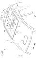
- FIG. 2 is a perspective view illustrating a roof panel of the vehicle in FIG. 1.
- the vehicle 10 includes a roof panel 12, a vehicle air conditioning system 14 provided on the roof panel 12, and a control device (not shown).
- the vehicle air conditioning system 14 includes a roof cover 16 that covers the roof panel 12, a ventilation path 18 formed between the roof panel 12 and the roof cover 16, and through which air can flow, and provided in the ventilation path 18.
- a cooling fan 22 that promotes the flow of air in the ventilation path 18.
- components of the air conditioning unit 20 except for a compressor 23 described later and a cooling fan 22 are not shown.
- illustration of the vehicle air conditioning system 14 is omitted.
- the vehicle 10 is preferably, for example, a small electric vehicle (MEV: Micro Electric Vehicle) or the like, but is not particularly limited to this.
- MEV Micro Electric Vehicle
- the front-back, up-down, left-right directions will be described according to the arrow directions shown in FIG. “Front” is the traveling direction of the vehicle 10 and “rear” is the opposite direction.
- “Left” and “right” are the left and right directions as viewed from the occupant P of the vehicle 10 facing forward.
- the roof panel 12 has a roof panel main body 26 having a mounting hole 24 formed therethrough, and a concave plate 28 mounted in the mounting hole 24.
- an air-conditioning outlet 32 communicating with a front end portion of a later-described duct 30 of the air-conditioning unit 20 is provided in the roof panel body 26 in front of a head PH of an occupant P seated in a driver seat S. It is formed through.
- a mounting hole 24 is provided behind the head PH of the occupant P sitting on the driver's seat S.
- the concave plate 28 is configured by integrally providing a housing portion 34 having an open top and a flange portion 36 provided at an opening edge of the housing portion 34.
- the bottom side of the housing portion 34 is inserted into the mounting hole 24, and a flange portion 36 is laminated on the upper surface of the roof panel main body 26 and on the outer peripheral edge of the mounting hole 24.
- a seal member (not shown) or the like may be interposed between the roof panel main body 26 and the flange portion 36 that are stacked.
- the laminated roof panel body 26 and the flange portion 36 may be bolted and fixed by bolts and nuts (not shown).
- the concave portion 38 in which the housing portion 34 of the concave plate 28 is depressed toward the cabin 40 is formed.
- the recess 38 accommodates a refrigeration cycle device 42 of the vehicle air conditioning system 14 described below.
- the recess 38 has a drainage hole 44 communicating with the outside of the vehicle 10 to allow water to be discharged from the ventilation passage 18, and a water guiding shape portion 46 for guiding water in the ventilation passage 18 to the drainage hole 44 by gravity or the like. Is provided. As shown in FIG. 3, the drain holes 44 are provided at both ends in the left-right direction at the rear of the vehicle 10. In the present embodiment, the drain holes 44 are formed below the left and right side walls 34 a of the housing 34 respectively. The drain hole 44 may be formed to penetrate the bottom 38 a of the recess 38 facing the roof cover 16. A drain tube 48 communicates with the drain hole 44, and the water in the ventilation path 18 flows into the drain tube 48 through the drain hole 44, so that the water can be led out of the vehicle 10. .
- the water guide shape portion 46 is inclined such that the bottom portion 38a of the concave portion 38 approaches the cabin 40 from the center in the left-right direction to the side (see FIG. 2), and the cabin increases from the front to the rear. It is formed by inclining in the direction approaching 40 (see FIG. 1). That is, the water that has flowed into the concave portion 38 is encouraged by the water guide shape portion 46 to flow downward in the vertical direction, in other words, toward both ends in the left-right direction and backward in the front-rear direction.
- the drainage hole 44 is guided to the drainage hole 44.
- the left side of the center line C (see FIG. 3) extending substantially in the center in the left-right direction is also referred to as a left concave portion 46L, and the right side of the center line C.
- One is also referred to as a right concave portion 46R.
- a convex portion 50 that projects upward is provided substantially at the center of the concave portion 38 in the left-right direction.
- an air-conditioning intake 52 is formed in the protruding end surface 50 a of the projection 50 as a communication hole that communicates the rear end of the duct 30 with the cabin 40.
- the roof cover 16 is provided so as to cover the roof panel 12, whereby the ventilation path 18 is formed between the roof cover 16 and the roof panel 12.
- the ventilation path 18 is formed between the roof cover 16 and the roof panel 12.
- an inlet 54 through which the traveling wind of the vehicle 10 can be taken into the ventilation path 18, and at the rear end of the ventilation path 18,
- An outlet 56 for discharging the air flowing through the air outlet 18 is provided. That is, running air and the like can be circulated through the ventilation path 18 from the inlet 54 to the outlet 56.
- the air conditioning unit 20 includes a duct 30 communicating with the cabin 40 of the vehicle 10 via an air conditioning intake 52 and an air conditioning outlet 32 formed through the roof panel 12, and a refrigeration cycle device 42 for cooling air in the duct 30. And a duct fan 58 that takes in the air in the cabin 40 into the duct 30 from the air conditioning intake 52 and blows out the air cooled by the refrigeration cycle device 42 (hereinafter, also referred to as cooling air) from the air conditioning outlet 32 to the cabin 40.
- the air-conditioning outlet 32 may be provided with a wind direction adjusting mechanism (not shown) capable of adjusting the direction in which the cooling air is blown out by using a louver or the like.
- the outer wall surface 30a above the duct 30 and the roof cover 16 are arranged apart from each other, and a space through which air can flow is formed therebetween.
- the duct 30 includes a front portion 60 communicating with the air conditioning outlet 32, a rear portion 62 communicating with the air conditioning intake 52, and a housing disposed between the front portion 60 and the rear portion 62.
- the part 64 is provided integrally.
- the front portion 60 is mainly disposed between the roof cover 16 and a portion of the roof panel body 26 in front of the mounting hole 24.
- the rear part 62 and the accommodation part 64 are disposed in the recess 38.
- the rear part 62 communicates with the air conditioning intake 52 by being connected to the protruding end face 50 a of the convex part 50.
- a duct fan 58 is provided inside the rear portion 62.
- the accommodation portion 64 has a height in the vertical direction that is larger than the front portion 60 and the rear portion 62, and accommodates an evaporator 66 of the refrigeration cycle device 42, which will be described later, inside the accommodation portion 64.
- the refrigeration cycle device 42 is configured by sequentially connecting the compressor 23, the condenser 70, an expansion valve (not shown), and the evaporator 66 via a refrigerant pipe (not shown).
- the compressor 23 is disposed outside the duct 30 in the air passage 18 and beside the duct fan 58 to compress the refrigerant. That is, as shown in FIG. 2, the compressor 23 is disposed to the left or right of the center (center line C) of the recess 38 in the left-right direction. In the present embodiment, the compressor 23 is disposed in the left concave portion 46L on the left side of the center line C of the concave portion 38.
- the compressor 23 may be provided in the right concave portion 46R.
- the compressor 23 is arranged so that its longitudinal direction is inclined with respect to the vertical direction.
- the angle (inclination angle ⁇ ) at which the longitudinal direction of the compressor 23 is inclined with respect to the vertical direction is set to 30 °.
- the inclination angle ⁇ is not limited to 30 °, and may be adjusted within a range of an allowable inclination angle determined according to the specifications of the compressor 23.
- a portion of the bottom 38 a of the concave portion 38 where the compressor 23 is disposed is provided with a housing groove 72 that is further depressed toward the cabin 40. Houses the compressor 23.
- the bottom surface of the storage groove 72 is inclined in a direction to guide water to the drain hole 44.
- the bottom surface of the accommodation groove 72 is, for example, from the center in the left-right direction to the left and from the front to the rear.
- a portion of the roof cover 16 facing the compressor 23 may be provided with an avoiding portion 16 a protruding upward from other portions of the roof cover 16. By providing the avoiding portion 16a, contact between the roof cover 16 and the compressor 23 is avoided.
- the condenser 70 is disposed behind the duct 30 in the air passage 18, and cools the refrigerant compressed by the compressor 23 by exchanging heat with the air in the air passage 18. And liquefy.
- the expansion valve decompresses the liquefied refrigerant and adiabatically expands the refrigerant.
- the evaporator 66 Since the evaporator 66 is disposed in the duct 30 as described above, the evaporator 66 is disposed in the ventilation path 18 ahead of the condenser 70. Further, the evaporator 66 cools the air by exchanging heat between the refrigerant, which has become low in temperature through the expansion valve, and the air in the cabin 40 taken into the duct 30.
- the cooling fan 22 is provided behind the condenser 70 in the ventilation path 18. By driving the cooling fan 22, a negative pressure is applied to the front of the cooling fan 22 in the ventilation path 18. This makes it possible to efficiently take air from the inlet 54 into the ventilation path 18 and circulate the air to the outlet 56.
- control device includes a control unit, an operation panel, and the like.
- the control unit is composed of a well-known microcomputer including a CPU, a ROM, a RAM, and the like, and peripheral circuits.
- a program for air-conditioning control and the like is stored in the ROM, and various calculations and processes are performed based on the program. I do.
- the operation panel is provided, for example, on or near the instrument panel 74 of the vehicle 10 shown in FIG. 1 and has an on / off switch (not shown) for the air conditioning unit 20 and the like.
- an on / off switch for the air conditioning unit 20 and the like.
- the occupant P operates the on / off switch of the air conditioning unit 20, it is possible to switch between starting and stopping the operation of the air conditioning unit 20, in other words, to start and stop supplying the cooling air to the cabin 40. ing.
- the vehicle 10 is basically configured as described above.
- the control unit puts the compressor 23, the duct fan 58, the cooling fan 22, and the like into an operating state.
- the compressor 23 By setting the compressor 23 to the operating state, the refrigerant circulates in the refrigerant pipe of the refrigeration cycle device 42 while changing the state, and the temperature of the evaporator 66 decreases.
- the air in the cabin 40 is taken into the duct 30 by setting the duct fan 58 in the operating state. This air is cooled by the heat exchange with the evaporator 66 whose temperature has decreased as described above, and is then blown out to the cabin 40. By circulating the air between the cabin 40 and the duct 30 in this manner, the cabin 40 is cooled.
- the cooling fan 22 By operating the cooling fan 22, the flow of air from the front to the rear in the ventilation path 18 is promoted. Thereby, the heat dissipation of the refrigerant in the condenser 70 is promoted, so that the cooling efficiency of the air conditioning unit 20 can be improved. Further, the temperature of the compressor 23 and the like can be prevented from rising, and the refrigeration cycle device 42 can be operated satisfactorily.
- the control unit operates the compressor 23, the duct fan 58, and the cooling fan 22. Is stopped. Thereby, the circulation of the refrigerant in the refrigeration cycle device 42 is stopped, and the circulation of the air between the cabin 40 and the duct 30 is stopped, so that the cooling of the cabin 40 is stopped.
- a refrigeration cycle device 42 whose height in the vertical direction tends to be larger among the air conditioning units 20 is provided in the concave portion 38 provided so as to be depressed toward the cabin 40 with respect to the roof panel 12. Will be accommodated. For this reason, even if the vehicle air conditioning system 14 is provided on the roof panel 12, an increase in vehicle height can be suppressed.
- rainwater or the like may enter along with the air.
- dew condensation water may be generated in the ventilation path 18 due to a temperature difference between the outside air temperature and the refrigerant in the refrigerant pipe.
- the recess 38 is provided with a drain hole 44 that communicates with the outside of the vehicle 10 and allows water to be discharged from the ventilation path 18.
- the concave portion 38 depressed toward the cabin 40 is disposed below the roof panel 12 in the vertical direction. For this reason, water in the ventilation path 18 such as rainwater and dew condensation water easily flows toward the recess 38 by gravity.
- the drainage hole 44 By providing the drainage hole 44 in such a concave portion 38, it becomes possible to drain well to the outside of the vehicle 10 through the drainage hole 44. Therefore, even if water enters the ventilation path 18 or water is generated in the ventilation path 18, it is possible to effectively suppress such water from remaining in the ventilation path 18.
- the arrangement and the number of the drain holes 44 are not particularly limited, and may be provided so that the water flowing into the concave portion 38 can be drained.
- the water guide shape portion 46 that is recessed toward the cabin 40 and guides water to the drain hole 44 is provided at the bottom 38 a of the recess 38 facing the roof cover 16. In this case, the water in the ventilation path 18 can be more effectively guided to the drain hole 44 by the water guide shape portion 46 and discharged to the outside of the vehicle 10.
- the water guide shape portion 46 is formed by inclining the bottom portion 38 a in a direction approaching the cabin 40 from the center in the left-right direction of the vehicle 10 toward the side, and the concave portion 38 has Drain holes 44 are provided at both ends in the direction.
- the water guide shape portion 46 is formed by inclining the bottom portion 38 a in a direction approaching the cabin 40 from one (front) to the other (rear) in the front-rear direction of the vehicle 10. 38, a drain hole 44 is provided at the other (rear) end in the front-rear direction.
- the water in the ventilation passage 18 can be effectively guided to the drain hole 44 and discharged to the outside of the vehicle 10 by the water guiding shape portion 46 having a simple configuration.
- the structure of the water guide shape portion 46 is not particularly limited as long as it can guide water to the drain hole 44 by using gravity.
- the water guide shape portion 46 may be a groove (not shown) provided in the bottom portion 38 a so as to communicate with the drain hole 44.
- the water guide shape portion 46 is inclined in a direction approaching the cabin 40 from one end side in the left-right direction to the other end side, and guides water to a drain hole 44 provided in the other end side in the left-right direction. It may be.
- the refrigeration cycle device 42 includes the compressor 23 that compresses the refrigerant, and the compressor 23 is disposed to the left or right of the center of the recess 38 in the left-right direction. .
- the left and right sides of the recess 38 are provided closer to the cabin 40 than the center. For this reason, it is possible to more effectively suppress the increase in the height of the vehicle 10 by arranging the compressor 23 in the refrigerating cycle device 42, the height of which in the vertical direction is likely to be large, in the recess 38. Becomes possible.
- the compressor 23 is arranged so that its longitudinal direction is inclined with respect to the vertical direction of the vehicle 10. As described above, by providing the compressor 23 in the recess 38 in a state where the compressor 23 is tilted within a range permitted according to the specifications and the like, it is possible to more effectively suppress the height of the vehicle 10 from increasing. it can.
- the compressor 23 may be provided along the vertical direction, that is, so that the inclination angle ⁇ is 0 °. Further, if permitted by the specifications of the compressor 23, the compressor 23 may be arranged so that the inclination angle ⁇ is 90 °, in other words, the longitudinal direction of the compressor 23 is along the front-rear direction or the left-right direction.
- a portion of the bottom portion 38a where the compressor 23 is disposed is provided with an accommodation groove 72 that is further depressed toward the cabin 40, and the accommodation groove 72 accommodates the compressor 23. did. This makes it possible to more effectively suppress the height of the vehicle 10 from increasing.
- the recess 38 may not be provided with the accommodation groove 72.
- the bottom surface of the accommodation groove 72 is inclined in a direction to guide water to the drain hole 44. Therefore, even if the accommodation groove 72 is provided to reduce the vehicle height as described above, it is possible to suppress the accumulation of water inside the accommodation groove 72. Further, by providing the roof cover 16 with the avoidance portion 16a as in the above-described embodiment, it is also possible to effectively reduce the vehicle height of the portion other than the avoidance portion 16a.
- a communication hole (air-conditioning intake port 52) for communicating one end (rear end) of the duct 30 with the cabin 40 is provided substantially at the center of the recess 38 in the left-right direction.
- the approximate center of the recess 38 in the left-right direction is located above both ends. For this reason, by providing a communication hole at substantially the center in the left-right direction of the concave portion 38, it is easy to prevent water in the ventilation path 18 from entering the duct 30 or the cabin 40 through the air-conditioning intake 52. Become.
- the air conditioning outlet 32 is provided in front of the roof panel 12 and the air conditioning intake 52 is provided in the rear, but the invention is not particularly limited to this.
- the air-conditioning intake port 52 may be provided in front of the roof panel 12 and the air-conditioning air outlet 32 may be provided behind. In this case, the communication hole becomes the air conditioning outlet 32.
- the concave portion 38 is arranged behind the occupant P seated in the driver's seat S behind. In this case, it is easy to secure a space above the occupant P in the driver's seat S. It should be noted that the arrangement of the concave portion 38 in the roof panel 12 is not particularly limited, and the concave portion 38 may be disposed at any position of the roof panel 12.
- the roof panel 12 has the roof panel main body 26 provided with the mounting holes 24 and the concave plate 28 which is mounted in the mounting holes 24 to form the concave portions 38.
- the roof panel 12 may be integrally formed from one member.
- the present invention is not particularly limited to the above-described embodiment, and various modifications can be made without departing from the gist of the present invention.
Abstract
A vehicle (10) comprising a roof panel (12) and a vehicle air conditioning system (14) provided in the roof panel (12). The vehicle air conditioning system (14) has: a roof cover (16) that covers the roof panel (12); an air passage (18) formed between the roof panel (12) and the roof cover (16) and through which air can flow; and an air conditioning unit (20) provided in the air passage (18). The air conditioning unit (20) has: a duct (30) connected to a cabin (40); and a cooling cycle device (42) that cools air taken into the duct (30) from the cabin (40). A recessed section (38) that sinks towards the cabin (40) is provided in the roof panel (12) and the cooling cycle device (42) is housed in the recessed section (38).
Description
本発明は、ルーフパネルに車両空調システムが設けられた車両に関する。
The present invention relates to a vehicle having a roof panel provided with a vehicle air conditioning system.
例えば、小型の電気自動車等の車両では、十分な走行距離を確保するべく、車両空調システムで消費される電力を低減することが求められる。このためには、車両に乗車した乗員に近い位置に冷却風の吹出口を設けて乗員に冷却風を効率的に供給することや、該吹出口の近傍に蒸発器を設けて配管距離を可及的に短くすること等が好ましい。このような吹出口や蒸発器の配置を可能とするため、例えば、特開2005-125896号公報に記載されるように、車両空調システムを車両のルーフパネルに設けることが考えられる。
For example, in vehicles such as small electric vehicles, it is required to reduce the power consumed by the vehicle air conditioning system in order to secure a sufficient traveling distance. For this purpose, a cooling air outlet is provided near the occupant in the vehicle to efficiently supply the cooling air to the occupant, or an evaporator is provided near the outlet to increase the piping distance. It is preferable to shorten as much as possible. In order to enable such an arrangement of the outlet and the evaporator, for example, it is conceivable to provide a vehicle air conditioning system on a roof panel of a vehicle as described in Japanese Patent Application Laid-Open No. 2005-125896.
しかしながら、車両空調システムをルーフパネルに設けた車両では、車両空調システムの高さの分、車高が増大するため、重心が高くなったり、空気抵抗を受け易くなったりする懸念がある。
However, in a vehicle provided with a vehicle air conditioning system on a roof panel, the height of the vehicle is increased by the height of the vehicle air conditioning system, so that there is a concern that the center of gravity may be increased or air resistance may be increased.
本発明の主たる目的は、車高が増大することを抑制しつつ、ルーフパネルに車両空調システムを設けることが可能な車両を提供することにある。
A main object of the present invention is to provide a vehicle capable of providing a vehicle air conditioning system on a roof panel while suppressing an increase in vehicle height.
本発明の一態様は、ルーフパネルに車両空調システムが設けられた車両であって、前記車両空調システムは、前記ルーフパネルを覆うルーフカバーと、前記ルーフパネルと前記ルーフカバーとの間に形成されるとともに、空気を流通させることが可能な通気路と、前記通気路に設けられた空調ユニットと、を有し、前記空調ユニットは、キャビンに連通するダクトと、前記キャビンから前記ダクトに取り込まれた空気を冷却する冷凍サイクル装置と、を有し、前記ルーフパネルには、キャビンに向かって陥没する凹部が設けられ、前記凹部に前記冷凍サイクル装置が収容される。
One embodiment of the present invention is a vehicle in which a vehicle air conditioning system is provided on a roof panel, wherein the vehicle air conditioning system is formed between a roof cover that covers the roof panel, and the roof panel and the roof cover. And a ventilation path through which air can flow, and an air conditioning unit provided in the ventilation path, wherein the air conditioning unit is taken into the duct from the cabin and the duct from the cabin. A refrigeration cycle device for cooling the cooled air, wherein the roof panel is provided with a concave portion that is depressed toward the cabin, and the concave portion accommodates the refrigeration cycle device.
この車両では、ルーフパネルに対しキャビンに向かって陥没するように設けられた凹部に、空調ユニットのなかでも上下方向の高さが大きくなり易い冷凍サイクル装置が収容される。このため、ルーフパネルに車両空調システムを設けても、車高が増大することを抑制できる。
で は In this vehicle, a refrigeration cycle device whose height in the vertical direction tends to be large among the air conditioning units is accommodated in a concave portion provided to be depressed toward the cabin with respect to the roof panel. Therefore, even if the vehicle air conditioning system is provided on the roof panel, it is possible to suppress an increase in vehicle height.
以下、本発明に係る車両について、好適な実施形態を挙げ、添付の図面を参照して詳細に説明する。なお、以下の図において、同一又は同様の機能及び効果を奏する構成要素に対しては同一の参照符号を付し、繰り返しの説明を省略する場合がある。
Hereinafter, a preferred embodiment of a vehicle according to the present invention will be described in detail with reference to the accompanying drawings. In the following drawings, components having the same or similar functions and effects are denoted by the same reference numerals, and repeated description may be omitted.
図1に示すように、本実施形態に係る車両10は、ルーフパネル12と、該ルーフパネル12に設けられた車両空調システム14と、不図示の制御装置とを備える。車両空調システム14は、ルーフパネル12を覆うルーフカバー16と、ルーフパネル12とルーフカバー16との間に形成されるとともに、空気を流通させることが可能な通気路18と、通気路18に設けられた空調ユニット20と、通気路18の空気の流通を促す冷却ファン22とを有する。なお、図2では、後述する圧縮機23を除く空調ユニット20の構成要素と、冷却ファン22の図示を省略している。また、図3では、車両空調システム14の図示を省略している。
As shown in FIG. 1, the vehicle 10 according to the present embodiment includes a roof panel 12, a vehicle air conditioning system 14 provided on the roof panel 12, and a control device (not shown). The vehicle air conditioning system 14 includes a roof cover 16 that covers the roof panel 12, a ventilation path 18 formed between the roof panel 12 and the roof cover 16, and through which air can flow, and provided in the ventilation path 18. And a cooling fan 22 that promotes the flow of air in the ventilation path 18. In FIG. 2, components of the air conditioning unit 20 except for a compressor 23 described later and a cooling fan 22 are not shown. In FIG. 3, illustration of the vehicle air conditioning system 14 is omitted.
なお、車両10は、例えば、小型の電気自動車(MEV:Micro Electric Vehicle)等であることが好ましいが、特にこれに限定されるものではない。また、以下では、図1に示す矢印方向に従って、前後、上下、左右の方向を説明する。「前方」は車両10の進行方向であり、「後方」はその逆方向である。「左方」及び「右方」は前方を向いた車両10の乗員Pから見た左右の方向である。
The vehicle 10 is preferably, for example, a small electric vehicle (MEV: Micro Electric Vehicle) or the like, but is not particularly limited to this. In addition, hereinafter, the front-back, up-down, left-right directions will be described according to the arrow directions shown in FIG. “Front” is the traveling direction of the vehicle 10 and “rear” is the opposite direction. “Left” and “right” are the left and right directions as viewed from the occupant P of the vehicle 10 facing forward.
図1及び図3に示すように、ルーフパネル12は、装着孔24が貫通形成されたルーフパネル本体26と、装着孔24に装着された凹部プレート28とを有する。図1に示すように、ルーフパネル本体26には、運転席Sに着座した乗員Pの頭部PHの前方側に、空調ユニット20の後述するダクト30の前端部と連通する空調吹出口32が貫通形成されている。また、ルーフパネル本体26のうち、運転席Sに着座した乗員Pの頭部PHよりも後方に装着孔24が設けられている。
As shown in FIGS. 1 and 3, the roof panel 12 has a roof panel main body 26 having a mounting hole 24 formed therethrough, and a concave plate 28 mounted in the mounting hole 24. As shown in FIG. 1, an air-conditioning outlet 32 communicating with a front end portion of a later-described duct 30 of the air-conditioning unit 20 is provided in the roof panel body 26 in front of a head PH of an occupant P seated in a driver seat S. It is formed through. In the roof panel main body 26, a mounting hole 24 is provided behind the head PH of the occupant P sitting on the driver's seat S.
凹部プレート28は、上方が開口した筐体部34と、筐体部34の開口縁部に設けられたフランジ部36とが一体に設けられて構成されている。装着孔24に装着された凹部プレート28では、装着孔24に筐体部34の底部側が挿入されるとともに、ルーフパネル本体26の上面であって装着孔24の外周縁部にフランジ部36が積層されている。なお、積層されたルーフパネル本体26とフランジ部36との間には、不図示のシール部材等を介在させてもよい。また、積層されたルーフパネル本体26とフランジ部36とは、不図示のボルトやナット等によってボルト止め固定されてもよい。
(4) The concave plate 28 is configured by integrally providing a housing portion 34 having an open top and a flange portion 36 provided at an opening edge of the housing portion 34. In the concave plate 28 mounted in the mounting hole 24, the bottom side of the housing portion 34 is inserted into the mounting hole 24, and a flange portion 36 is laminated on the upper surface of the roof panel main body 26 and on the outer peripheral edge of the mounting hole 24. Have been. Note that a seal member (not shown) or the like may be interposed between the roof panel main body 26 and the flange portion 36 that are stacked. The laminated roof panel body 26 and the flange portion 36 may be bolted and fixed by bolts and nuts (not shown).
上記のように、ルーフパネル本体26の装着孔24に凹部プレート28を装着して形成したルーフパネル12では、凹部プレート28の筐体部34がキャビン40に向かって陥没する凹部38を形成する。この凹部38には、車両空調システム14の後述する冷凍サイクル装置42が収容される。
As described above, in the roof panel 12 formed by mounting the concave plate 28 in the mounting hole 24 of the roof panel main body 26, the concave portion 38 in which the housing portion 34 of the concave plate 28 is depressed toward the cabin 40 is formed. The recess 38 accommodates a refrigeration cycle device 42 of the vehicle air conditioning system 14 described below.
また、凹部38には、車両10の外部に連通して通気路18から水を排出可能とする排水孔44と、通気路18内の水を重力等により排水孔44に導く導水形状部46とが設けられる。図3に示すように、排水孔44は、車両10の後方であって、左右方向の両端側にそれぞれ設けられる。本実施形態では、排水孔44は、筐体部34の左右の側壁34aの下方にそれぞれ貫通形成されている。なお、排水孔44は、凹部38のルーフカバー16と対向する底部38aに貫通形成されてもよい。また、排水孔44にはドレインチューブ48が連通され、通気路18内の水を排水孔44を介してドレインチューブ48に流入させることで、車両10の外部に導出することが可能になっている。
The recess 38 has a drainage hole 44 communicating with the outside of the vehicle 10 to allow water to be discharged from the ventilation passage 18, and a water guiding shape portion 46 for guiding water in the ventilation passage 18 to the drainage hole 44 by gravity or the like. Is provided. As shown in FIG. 3, the drain holes 44 are provided at both ends in the left-right direction at the rear of the vehicle 10. In the present embodiment, the drain holes 44 are formed below the left and right side walls 34 a of the housing 34 respectively. The drain hole 44 may be formed to penetrate the bottom 38 a of the recess 38 facing the roof cover 16. A drain tube 48 communicates with the drain hole 44, and the water in the ventilation path 18 flows into the drain tube 48 through the drain hole 44, so that the water can be led out of the vehicle 10. .
導水形状部46は、凹部38の底部38aが、左右方向の中央から側方に向かうに連れてキャビン40に接近する方向に傾斜する(図2参照)とともに、前方から後方に向かうに連れてキャビン40に接近する方向に傾斜する(図1参照)ことで形成される。すなわち、凹部38に流入した水は、導水形状部46によって、上下方向の下方、換言すると、左右方向の両端側且つ前後方向の後方に向かって流通することが促されるため、上記のように配置された排水孔44へと導かれる。なお、以下では、導水形状部46のうち、左右方向の略中央を前後方向に延在する中心線C(図3参照)よりも左方を左側凹状部46Lともいい、中心線Cよりも右方を右側凹状部46Rともいう。
The water guide shape portion 46 is inclined such that the bottom portion 38a of the concave portion 38 approaches the cabin 40 from the center in the left-right direction to the side (see FIG. 2), and the cabin increases from the front to the rear. It is formed by inclining in the direction approaching 40 (see FIG. 1). That is, the water that has flowed into the concave portion 38 is encouraged by the water guide shape portion 46 to flow downward in the vertical direction, in other words, toward both ends in the left-right direction and backward in the front-rear direction. The drainage hole 44 is guided to the drainage hole 44. In the following, of the water guide shape portion 46, the left side of the center line C (see FIG. 3) extending substantially in the center in the left-right direction is also referred to as a left concave portion 46L, and the right side of the center line C. One is also referred to as a right concave portion 46R.
図2及び図3に示すように、凹部38の左右方向の略中央には、上方に向かって突出する凸部50が設けられる。図1に示すように、凸部50の突出端面50aには、ダクト30の後端部とキャビン40とを連通する連通孔として、空調取込口52が貫通形成されている。
及 び As shown in FIGS. 2 and 3, a convex portion 50 that projects upward is provided substantially at the center of the concave portion 38 in the left-right direction. As shown in FIG. 1, an air-conditioning intake 52 is formed in the protruding end surface 50 a of the projection 50 as a communication hole that communicates the rear end of the duct 30 with the cabin 40.
上記の通り、ルーフカバー16は、ルーフパネル12を覆うように配設され、これによって、ルーフカバー16とルーフパネル12との間に通気路18が形成される。図1に示すように、通気路18の前端には、車両10の走行風等を該通気路18に取り込むことが可能な導入口54が設けられ、通気路18の後端には、通気路18を流通した空気を排出する排出口56が設けられている。すなわち、通気路18には、導入口54から排出口56に向かって走行風等を流通させることが可能になっている。
As described above, the roof cover 16 is provided so as to cover the roof panel 12, whereby the ventilation path 18 is formed between the roof cover 16 and the roof panel 12. As shown in FIG. 1, at the front end of the ventilation path 18, there is provided an inlet 54 through which the traveling wind of the vehicle 10 can be taken into the ventilation path 18, and at the rear end of the ventilation path 18, An outlet 56 for discharging the air flowing through the air outlet 18 is provided. That is, running air and the like can be circulated through the ventilation path 18 from the inlet 54 to the outlet 56.
空調ユニット20は、ルーフパネル12に貫通形成された空調取込口52及び空調吹出口32を介して車両10のキャビン40に連通するダクト30と、ダクト30内の空気を冷却する冷凍サイクル装置42と、キャビン40の空気を空調取込口52からダクト30に取り込むともに、冷凍サイクル装置42で冷却された空気(以下、冷却風ともいう)を空調吹出口32からキャビン40に吹き出すダクトファン58とを有する。なお、空調吹出口32には、冷却風が吹き出される方向を、ルーバー等により調整可能な風向調整機構(不図示)が設けられてもよい。また、ダクト30の上方の外壁面30aと、ルーフカバー16とは離間して配置され、互いの間に空気が流通することが可能なスペースが形成されている。
The air conditioning unit 20 includes a duct 30 communicating with the cabin 40 of the vehicle 10 via an air conditioning intake 52 and an air conditioning outlet 32 formed through the roof panel 12, and a refrigeration cycle device 42 for cooling air in the duct 30. And a duct fan 58 that takes in the air in the cabin 40 into the duct 30 from the air conditioning intake 52 and blows out the air cooled by the refrigeration cycle device 42 (hereinafter, also referred to as cooling air) from the air conditioning outlet 32 to the cabin 40. Having. The air-conditioning outlet 32 may be provided with a wind direction adjusting mechanism (not shown) capable of adjusting the direction in which the cooling air is blown out by using a louver or the like. Further, the outer wall surface 30a above the duct 30 and the roof cover 16 are arranged apart from each other, and a space through which air can flow is formed therebetween.
具体的には、ダクト30は、空調吹出口32と連通する前方部60と、空調取込口52と連通する後方部62と、前方部60と後方部62との間に配設される収容部64とが一体に設けられて構成されている。前方部60は、ルーフパネル本体26の装着孔24より前方の部分と、ルーフカバー16との間に主に配設される。後方部62及び収容部64は、凹部38内に配設される。後方部62は、凸部50の突出端面50aと接続されることで、空調取込口52と連通する。また、後方部62の内部には、ダクトファン58が配設されている。収容部64は、上下方向の高さが前方部60及び後方部62に比して大きく、該収容部64の内部に冷凍サイクル装置42の後述する蒸発器66が収容されている。
Specifically, the duct 30 includes a front portion 60 communicating with the air conditioning outlet 32, a rear portion 62 communicating with the air conditioning intake 52, and a housing disposed between the front portion 60 and the rear portion 62. The part 64 is provided integrally. The front portion 60 is mainly disposed between the roof cover 16 and a portion of the roof panel body 26 in front of the mounting hole 24. The rear part 62 and the accommodation part 64 are disposed in the recess 38. The rear part 62 communicates with the air conditioning intake 52 by being connected to the protruding end face 50 a of the convex part 50. A duct fan 58 is provided inside the rear portion 62. The accommodation portion 64 has a height in the vertical direction that is larger than the front portion 60 and the rear portion 62, and accommodates an evaporator 66 of the refrigeration cycle device 42, which will be described later, inside the accommodation portion 64.
冷凍サイクル装置42は、圧縮機23と、凝縮器70と、不図示の膨張弁と、蒸発器66とが不図示の冷媒配管を介して順次接続されて構成される。圧縮機23は、通気路18内におけるダクト30の外部であって、ダクトファン58の側方に配設され、冷媒を圧縮する。すなわち、図2に示すように、圧縮機23は、凹部38の左右方向の中央(中心線C)よりも左方又は右方に配設される。本実施形態では、圧縮機23は、凹部38の中心線Cよりも左方の左側凹状部46Lに配設される。なお、圧縮機23は、右側凹状部46Rに配設されてもよい。
The refrigeration cycle device 42 is configured by sequentially connecting the compressor 23, the condenser 70, an expansion valve (not shown), and the evaporator 66 via a refrigerant pipe (not shown). The compressor 23 is disposed outside the duct 30 in the air passage 18 and beside the duct fan 58 to compress the refrigerant. That is, as shown in FIG. 2, the compressor 23 is disposed to the left or right of the center (center line C) of the recess 38 in the left-right direction. In the present embodiment, the compressor 23 is disposed in the left concave portion 46L on the left side of the center line C of the concave portion 38. The compressor 23 may be provided in the right concave portion 46R.
また、圧縮機23は、その長手方向が上下方向に対し傾斜して配置される。本実施形態では、圧縮機23の長手方向が上下方向に対して傾斜する角度(傾斜角度θ)は30°に設定されている。なお、傾斜角度θは、30°に限定されるものではなく、圧縮機23の仕様に応じて定められた許容傾斜角度の範囲内で調整されればよい。
圧 縮 The compressor 23 is arranged so that its longitudinal direction is inclined with respect to the vertical direction. In the present embodiment, the angle (inclination angle θ) at which the longitudinal direction of the compressor 23 is inclined with respect to the vertical direction is set to 30 °. Note that the inclination angle θ is not limited to 30 °, and may be adjusted within a range of an allowable inclination angle determined according to the specifications of the compressor 23.
また、図2及び図3に示すように、凹部38の底部38aのうち、圧縮機23が配置される部分には、キャビン40に向かってさらに陥没する収容溝72が設けられ、該収容溝72に圧縮機23が収容される。収容溝72の底面は、排水孔44に水を導く方向に傾斜している。本実施形態のように左側凹状部46Lに収容溝72が設けられる場合、収容溝72の底面は、例えば、左右方向の中央側から左方に向かうに連れ、且つ前方から後方に向かうに連れてキャビン40に接近する方向(下方)に傾斜することで、排水孔44に水を導くことが可能になっている。このため、たとえ、収容溝72に水が流入したとしても、該水を収容溝72の内部を介して排水孔44へと導くことが可能になっている。
As shown in FIGS. 2 and 3, a portion of the bottom 38 a of the concave portion 38 where the compressor 23 is disposed is provided with a housing groove 72 that is further depressed toward the cabin 40. Houses the compressor 23. The bottom surface of the storage groove 72 is inclined in a direction to guide water to the drain hole 44. When the accommodation groove 72 is provided in the left concave portion 46L as in the present embodiment, the bottom surface of the accommodation groove 72 is, for example, from the center in the left-right direction to the left and from the front to the rear. By inclining in a direction (downward) approaching the cabin 40, it is possible to guide water to the drain holes 44. Therefore, even if water flows into the storage groove 72, the water can be guided to the drain hole 44 through the inside of the storage groove 72.
さらに、図1及び図2に示すように、ルーフカバー16の圧縮機23に臨む部分には、該ルーフカバー16の他部位よりも上方に向かって突出する回避部16aが設けられてもよい。回避部16aが設けられることで、ルーフカバー16と圧縮機23との接触が回避されている。
Further, as shown in FIGS. 1 and 2, a portion of the roof cover 16 facing the compressor 23 may be provided with an avoiding portion 16 a protruding upward from other portions of the roof cover 16. By providing the avoiding portion 16a, contact between the roof cover 16 and the compressor 23 is avoided.
図1に示すように、凝縮器70は、通気路18内におけるダクト30よりも後方に配設され、圧縮機23で圧縮された冷媒を、通気路18内の空気と熱交換させることにより冷却して、液化させる。膨張弁は、液化した冷媒を減圧して断熱膨張させる。
As shown in FIG. 1, the condenser 70 is disposed behind the duct 30 in the air passage 18, and cools the refrigerant compressed by the compressor 23 by exchanging heat with the air in the air passage 18. And liquefy. The expansion valve decompresses the liquefied refrigerant and adiabatically expands the refrigerant.
蒸発器66は、上記の通り、ダクト30内に配設されるため、通気路18内の凝縮器70よりも前方に配置される。また、蒸発器66は、膨張弁を経て低温となった冷媒と、ダクト30内に取り込まれたキャビン40の空気とを熱交換させることで、該空気を冷却する。
(4) Since the evaporator 66 is disposed in the duct 30 as described above, the evaporator 66 is disposed in the ventilation path 18 ahead of the condenser 70. Further, the evaporator 66 cools the air by exchanging heat between the refrigerant, which has become low in temperature through the expansion valve, and the air in the cabin 40 taken into the duct 30.
冷却ファン22は、通気路18内の凝縮器70よりも後方に設けられる。冷却ファン22を駆動することで、通気路18内の冷却ファン22よりも前方が負圧となる。これによって、導入口54から通気路18に空気を効率的に取り込んで、排出口56へと流通させることが可能になる。
The cooling fan 22 is provided behind the condenser 70 in the ventilation path 18. By driving the cooling fan 22, a negative pressure is applied to the front of the cooling fan 22 in the ventilation path 18. This makes it possible to efficiently take air from the inlet 54 into the ventilation path 18 and circulate the air to the outlet 56.
制御装置は、何れも不図示ではあるが、制御部や、操作パネル等を有する。制御部は、CPU、ROM、RAM等を含む周知のマイクロコンピュータと、その周辺回路から構成され、ROM内に空調制御等のためのプログラムを記憶しており、そのプログラムに基づいて各種演算、処理を行う。
Although not shown, the control device includes a control unit, an operation panel, and the like. The control unit is composed of a well-known microcomputer including a CPU, a ROM, a RAM, and the like, and peripheral circuits. A program for air-conditioning control and the like is stored in the ROM, and various calculations and processes are performed based on the program. I do.
操作パネルは、例えば、図1に示す、車両10のインストルメントパネル74又はその近傍に設けられ、空調ユニット20のオンオフスイッチ(不図示)等を有する。例えば、乗員Pが空調ユニット20のオンオフスイッチを操作することで、空調ユニット20の起動及び動作停止を切り換えること、換言すると、キャビン40に対する冷却風の供給開始及び供給停止を切り換えることが可能になっている。
The operation panel is provided, for example, on or near the instrument panel 74 of the vehicle 10 shown in FIG. 1 and has an on / off switch (not shown) for the air conditioning unit 20 and the like. For example, when the occupant P operates the on / off switch of the air conditioning unit 20, it is possible to switch between starting and stopping the operation of the air conditioning unit 20, in other words, to start and stop supplying the cooling air to the cabin 40. ing.
本実施形態に係る車両10は、基本的には以上のように構成される。この車両10では、オンオフスイッチの操作により、空調ユニット20を起動することが選択された場合、制御部は、圧縮機23、ダクトファン58、冷却ファン22等を動作状態とする。
車 両 The vehicle 10 according to the present embodiment is basically configured as described above. In the vehicle 10, when the activation of the air conditioning unit 20 is selected by operating the on / off switch, the control unit puts the compressor 23, the duct fan 58, the cooling fan 22, and the like into an operating state.
圧縮機23を動作状態とすることで、冷凍サイクル装置42の冷媒配管内を冷媒が状態変化しながら循環し、蒸発器66の温度が低下する。また、ダクトファン58を動作状態とすることで、キャビン40の空気がダクト30に取り込まれる。この空気は、上記のように温度が低下した蒸発器66と熱交換することにより冷却風となった後、キャビン40に吹き出される。このようにしてキャビン40とダクト30との間で空気を循環させることで、キャビン40が冷却される。
と す る By setting the compressor 23 to the operating state, the refrigerant circulates in the refrigerant pipe of the refrigeration cycle device 42 while changing the state, and the temperature of the evaporator 66 decreases. The air in the cabin 40 is taken into the duct 30 by setting the duct fan 58 in the operating state. This air is cooled by the heat exchange with the evaporator 66 whose temperature has decreased as described above, and is then blown out to the cabin 40. By circulating the air between the cabin 40 and the duct 30 in this manner, the cabin 40 is cooled.
さらに、冷却ファン22を動作状態とすることで、通気路18内を前方から後方に向かう空気の流通が促される。これによって、凝縮器70での冷媒の放熱が促されるため、空調ユニット20による冷却効率を向上させることができる。また、圧縮機23等の温度が上昇することを抑制して、冷凍サイクル装置42を良好に動作させることができる。
Furthermore, by operating the cooling fan 22, the flow of air from the front to the rear in the ventilation path 18 is promoted. Thereby, the heat dissipation of the refrigerant in the condenser 70 is promoted, so that the cooling efficiency of the air conditioning unit 20 can be improved. Further, the temperature of the compressor 23 and the like can be prevented from rising, and the refrigeration cycle device 42 can be operated satisfactorily.
一方、オンオフスイッチの操作により、空調ユニット20の動作を停止することが選択された場合や、車両電源をオフした場合には、制御部は、圧縮機23、ダクトファン58、冷却ファン22の動作を停止状態とする。これによって、冷凍サイクル装置42における冷媒の循環が停止するとともに、キャビン40とダクト30との間の空気の循環が停止して、キャビン40の冷却が停止される。
On the other hand, when it is selected to stop the operation of the air conditioning unit 20 by operating the on / off switch or when the vehicle power is turned off, the control unit operates the compressor 23, the duct fan 58, and the cooling fan 22. Is stopped. Thereby, the circulation of the refrigerant in the refrigeration cycle device 42 is stopped, and the circulation of the air between the cabin 40 and the duct 30 is stopped, so that the cooling of the cabin 40 is stopped.
本実施形態に係る車両10では、ルーフパネル12に対しキャビン40に向かって陥没するように設けられた凹部38に、空調ユニット20のなかでも上下方向の高さが大きくなり易い冷凍サイクル装置42が収容される。このため、ルーフパネル12に車両空調システム14を設けても、車高が増大することを抑制できる。
In the vehicle 10 according to the present embodiment, a refrigeration cycle device 42 whose height in the vertical direction tends to be larger among the air conditioning units 20 is provided in the concave portion 38 provided so as to be depressed toward the cabin 40 with respect to the roof panel 12. Will be accommodated. For this reason, even if the vehicle air conditioning system 14 is provided on the roof panel 12, an increase in vehicle height can be suppressed.
ところで、車両10の通気路18には、車両10が走行することや、冷却ファン22を動作させることや、自然風が吹き込むこと等により、上記の通り導入口54を介して空気が流入するが、この空気とともに雨水等が進入する場合がある。さらに、冷凍サイクル装置42を動作させると、外気温と冷媒配管内の冷媒との温度差等から、通気路18内に結露水が生じる場合もある。
By the way, air flows into the ventilation path 18 of the vehicle 10 through the inlet 54 as described above due to the running of the vehicle 10, the operation of the cooling fan 22, and the blowing of natural wind. However, rainwater or the like may enter along with the air. Further, when the refrigeration cycle device 42 is operated, dew condensation water may be generated in the ventilation path 18 due to a temperature difference between the outside air temperature and the refrigerant in the refrigerant pipe.
上記の車両10では、凹部38に、車両10の外部に連通して通気路18から水を排出可能とする排水孔44が設けられることとした。キャビン40側に向かって陥没する凹部38は、ルーフパネル12の他部位よりも上下方向の下方に配置される。このため、雨水や結露水等の通気路18内の水は、重力により凹部38に向かって流れ易くなっている。このような凹部38に排水孔44を設けることで、該排水孔44を介して車両10の外部に良好に排水することが可能になる。従って、通気路18内に水が進入したり、通気路18内で水が発生したりしても、これらの水が通気路18内に留まることを効果的に抑制できる。なお、排水孔44の配置や個数は、特に限定されるものではなく、凹部38に流入した水を排水可能となるように設けられればよい。
車 両 In the vehicle 10 described above, the recess 38 is provided with a drain hole 44 that communicates with the outside of the vehicle 10 and allows water to be discharged from the ventilation path 18. The concave portion 38 depressed toward the cabin 40 is disposed below the roof panel 12 in the vertical direction. For this reason, water in the ventilation path 18 such as rainwater and dew condensation water easily flows toward the recess 38 by gravity. By providing the drainage hole 44 in such a concave portion 38, it becomes possible to drain well to the outside of the vehicle 10 through the drainage hole 44. Therefore, even if water enters the ventilation path 18 or water is generated in the ventilation path 18, it is possible to effectively suppress such water from remaining in the ventilation path 18. In addition, the arrangement and the number of the drain holes 44 are not particularly limited, and may be provided so that the water flowing into the concave portion 38 can be drained.
上記の車両10では、凹部38のルーフカバー16と対向する底部38aには、キャビン40側に向かって凹み、水を排水孔44に導く導水形状部46が設けられることとした。この場合、導水形状部46によって通気路18内の水を一層効果的に排水孔44に導いて、車両10の外部へと排出することが可能になる。
で は In the vehicle 10 described above, the water guide shape portion 46 that is recessed toward the cabin 40 and guides water to the drain hole 44 is provided at the bottom 38 a of the recess 38 facing the roof cover 16. In this case, the water in the ventilation path 18 can be more effectively guided to the drain hole 44 by the water guide shape portion 46 and discharged to the outside of the vehicle 10.
上記の車両10では、導水形状部46は、底部38aが車両10の左右方向の中央から側方に向かうに連れてキャビン40に接近する方向に傾斜することで形成され、凹部38には、左右方向の両端側に排水孔44がそれぞれ設けられることとした。
In the above-described vehicle 10, the water guide shape portion 46 is formed by inclining the bottom portion 38 a in a direction approaching the cabin 40 from the center in the left-right direction of the vehicle 10 toward the side, and the concave portion 38 has Drain holes 44 are provided at both ends in the direction.
上記の車両10では、導水形状部46は、底部38aが車両10の前後方向の一方(前方)から他方(後方)に向かうに連れてキャビン40に接近する方向に傾斜することで形成され、凹部38には、前後方向の他方(後方)の端部に排水孔44が設けられることとした。
In the above-described vehicle 10, the water guide shape portion 46 is formed by inclining the bottom portion 38 a in a direction approaching the cabin 40 from one (front) to the other (rear) in the front-rear direction of the vehicle 10. 38, a drain hole 44 is provided at the other (rear) end in the front-rear direction.
これらの場合、簡単な構成の導水形状部46によって、通気路18内の水を効果的に排水孔44に導いて、車両10の外部へと排出することが可能になる。
In these cases, the water in the ventilation passage 18 can be effectively guided to the drain hole 44 and discharged to the outside of the vehicle 10 by the water guiding shape portion 46 having a simple configuration.
なお、導水形状部46の構造は、排水孔44に重力を利用して水を導くことが可能な形状であれば特に限定されるものではない。例えば、導水形状部46は、排水孔44に連通するように、底部38aに設けられた溝(不図示)であってもよい。また、導水形状部46は、左右方向の一端側から他端側に向かうに連れてキャビン40に接近する方向に傾斜し、左右方向の他端側に設けられた排水孔44に水を導くこととしてもよい。
The structure of the water guide shape portion 46 is not particularly limited as long as it can guide water to the drain hole 44 by using gravity. For example, the water guide shape portion 46 may be a groove (not shown) provided in the bottom portion 38 a so as to communicate with the drain hole 44. Further, the water guide shape portion 46 is inclined in a direction approaching the cabin 40 from one end side in the left-right direction to the other end side, and guides water to a drain hole 44 provided in the other end side in the left-right direction. It may be.
上記の車両10では、冷凍サイクル装置42は、冷媒を圧縮する圧縮機23を有し、圧縮機23は、凹部38の左右方向の中央よりも左方又は右方に配設されることとした。上記の通り、凹部38の左右方向の両側は中央よりもキャビン40に接近して設けられる。このため、冷凍サイクル装置42のなかでも上下方向の高さが大きくなり易い圧縮機23を、凹部38に配設することで、車両10の車高が高くなることをより効果的に抑制することが可能になる。
In the vehicle 10 described above, the refrigeration cycle device 42 includes the compressor 23 that compresses the refrigerant, and the compressor 23 is disposed to the left or right of the center of the recess 38 in the left-right direction. . As described above, the left and right sides of the recess 38 are provided closer to the cabin 40 than the center. For this reason, it is possible to more effectively suppress the increase in the height of the vehicle 10 by arranging the compressor 23 in the refrigerating cycle device 42, the height of which in the vertical direction is likely to be large, in the recess 38. Becomes possible.
上記の車両10では、圧縮機23は、その長手方向が車両10の上下方向に対し傾斜して配置されることとした。このように、圧縮機23をその仕様等に応じて許容された範囲内で傾斜させた状態で凹部38に設けることで、車両10の車高が高くなることをさらに効果的に抑制することができる。なお、圧縮機23は、上下方向に沿って、すなわち、傾斜角度θが0°となるように設けられてもよい。また、圧縮機23の仕様等により許容されれば、傾斜角度θが90°となるように、換言すると、圧縮機23の長手方向が前後方向や左右方向に沿うように配置されてもよい。
で は In the vehicle 10 described above, the compressor 23 is arranged so that its longitudinal direction is inclined with respect to the vertical direction of the vehicle 10. As described above, by providing the compressor 23 in the recess 38 in a state where the compressor 23 is tilted within a range permitted according to the specifications and the like, it is possible to more effectively suppress the height of the vehicle 10 from increasing. it can. The compressor 23 may be provided along the vertical direction, that is, so that the inclination angle θ is 0 °. Further, if permitted by the specifications of the compressor 23, the compressor 23 may be arranged so that the inclination angle θ is 90 °, in other words, the longitudinal direction of the compressor 23 is along the front-rear direction or the left-right direction.
上記の車両10では、底部38aのうち、圧縮機23が配置される部分には、キャビン40に向かってさらに陥没する収容溝72が設けられ、収容溝72に圧縮機23が収容されることとした。これによって、車両10の車高が高くなることを一層効果的に抑制することが可能になる。なお、凹部38には収容溝72が設けられていなくてもよい。
In the vehicle 10 described above, a portion of the bottom portion 38a where the compressor 23 is disposed is provided with an accommodation groove 72 that is further depressed toward the cabin 40, and the accommodation groove 72 accommodates the compressor 23. did. This makes it possible to more effectively suppress the height of the vehicle 10 from increasing. The recess 38 may not be provided with the accommodation groove 72.
上記の車両10では、収容溝72の底面は、排水孔44に水を導く方向に傾斜していることとした。これによって、上記の通り車高を低減するべく収容溝72を設けても、該収容溝72の内部に水が溜まることを抑制できる。さらに、上記の実施形態のように、ルーフカバー16に回避部16aを設けることによっても、該回避部16aを除く部分の車高を効果的に低減することが可能になる。
で は In the vehicle 10 described above, the bottom surface of the accommodation groove 72 is inclined in a direction to guide water to the drain hole 44. Thereby, even if the accommodation groove 72 is provided to reduce the vehicle height as described above, it is possible to suppress the accumulation of water inside the accommodation groove 72. Further, by providing the roof cover 16 with the avoidance portion 16a as in the above-described embodiment, it is also possible to effectively reduce the vehicle height of the portion other than the avoidance portion 16a.
上記の車両10では、凹部38の左右方向の略中央に、ダクト30の一端部(後端部)とキャビン40とを連通する連通孔(空調取込口52)が設けられることとした。凹部38の左右方向の略中央は、両端側よりも上方に位置する。このため、凹部38の左右方向の略中央に連通孔を設けることで、空調取込口52を介して通気路18内の水がダクト30やキャビン40に進入することを回避することが容易になる。
で は In the vehicle 10 described above, a communication hole (air-conditioning intake port 52) for communicating one end (rear end) of the duct 30 with the cabin 40 is provided substantially at the center of the recess 38 in the left-right direction. The approximate center of the recess 38 in the left-right direction is located above both ends. For this reason, by providing a communication hole at substantially the center in the left-right direction of the concave portion 38, it is easy to prevent water in the ventilation path 18 from entering the duct 30 or the cabin 40 through the air-conditioning intake 52. Become.
なお、上記の実施形態では、ルーフパネル12の前方に空調吹出口32を設けるとともに、後方に空調取込口52を設けることとしたが、特にこれに限定されるものではない。例えば、ルーフパネル12の前方に空調取込口52を設けるとともに、後方に空調吹出口32を設けてもよい。この場合、連通孔は、空調吹出口32となる。
In the above embodiment, the air conditioning outlet 32 is provided in front of the roof panel 12 and the air conditioning intake 52 is provided in the rear, but the invention is not particularly limited to this. For example, the air-conditioning intake port 52 may be provided in front of the roof panel 12 and the air-conditioning air outlet 32 may be provided behind. In this case, the communication hole becomes the air conditioning outlet 32.
上記の車両10では、凹部38は、運転席Sに着座した乗員Pの上方よりも後方に配置されていることとした。この場合、運転席Sに乗車した乗員Pの上方にスペースを確保することが容易になる。なお、ルーフパネル12における凹部38の配置は特に限定されるものではなく、ルーフパネル12の何れの箇所に凹部38が配置されてもよい。
で は In the vehicle 10 described above, the concave portion 38 is arranged behind the occupant P seated in the driver's seat S behind. In this case, it is easy to secure a space above the occupant P in the driver's seat S. It should be noted that the arrangement of the concave portion 38 in the roof panel 12 is not particularly limited, and the concave portion 38 may be disposed at any position of the roof panel 12.
上記の車両10では、ルーフパネル12は、装着孔24が設けられたルーフパネル本体26と、装着孔24に装着されることで、凹部38を形成する凹部プレート28とを有することとした。この場合、別体からなるルーフパネル本体26と凹部プレート28とをそれぞれ形成してから組み合わせることによって、凹部38を有するルーフパネル12であっても容易に製造することが可能になる。なお、ルーフパネル12は、一つの部材から一体に形成されてもよい。
In the vehicle 10 described above, the roof panel 12 has the roof panel main body 26 provided with the mounting holes 24 and the concave plate 28 which is mounted in the mounting holes 24 to form the concave portions 38. In this case, it is possible to easily manufacture even the roof panel 12 having the concave portion 38 by forming and combining the roof panel main body 26 and the concave plate 28 which are formed separately. Note that the roof panel 12 may be integrally formed from one member.
本発明は、上記した実施形態に特に限定されるものではなく、その要旨を逸脱しない範囲で種々の変形が可能である。
The present invention is not particularly limited to the above-described embodiment, and various modifications can be made without departing from the gist of the present invention.
10…車両 12…ルーフパネル
14…車両空調システム 16…ルーフカバー
18…通気路 20…空調ユニット
23…圧縮機 24…装着孔
26…ルーフパネル本体 28…凹部プレート
30…ダクト 32…空調吹出口
38…凹部 38a…底部
40…キャビン 42…冷凍サイクル装置
44…排水孔 46…導水形状部
52…空調取込口 P…乗員
S…運転席 DESCRIPTION OFSYMBOLS 10 ... Vehicle 12 ... Roof panel 14 ... Vehicle air-conditioning system 16 ... Roof cover 18 ... Ventilation path 20 ... Air-conditioning unit 23 ... Compressor 24 ... Mounting hole 26 ... Roof panel main body 28 ... Concave plate 30 ... Duct 32 ... Air-conditioning air outlet 38 ... recess 38a ... bottom 40 ... cabin 42 ... refrigeration cycle device 44 ... drainage hole 46 ... water guide shape part 52 ... air conditioning intake P ... occupant S ... driver's seat
14…車両空調システム 16…ルーフカバー
18…通気路 20…空調ユニット
23…圧縮機 24…装着孔
26…ルーフパネル本体 28…凹部プレート
30…ダクト 32…空調吹出口
38…凹部 38a…底部
40…キャビン 42…冷凍サイクル装置
44…排水孔 46…導水形状部
52…空調取込口 P…乗員
S…運転席 DESCRIPTION OF
Claims (12)
- ルーフパネル(12)に車両空調システム(14)が設けられた車両(10)であって、
前記車両空調システムは、前記ルーフパネルを覆うルーフカバー(16)と、前記ルーフパネルと前記ルーフカバーとの間に形成されるとともに、空気を流通させることが可能な通気路(18)と、前記通気路に設けられた空調ユニット(20)と、を有し、
前記空調ユニットは、キャビン(40)に連通するダクト(30)と、前記キャビンから前記ダクトに取り込まれた空気を冷却する冷凍サイクル装置(42)と、を有し、
前記ルーフパネルには、前記キャビンに向かって陥没する凹部(38)が設けられ、
前記凹部に前記冷凍サイクル装置が収容される、車両。 A vehicle (10) provided with a vehicle air conditioning system (14) on a roof panel (12),
The vehicle air conditioning system includes a roof cover (16) that covers the roof panel, an air passage (18) formed between the roof panel and the roof cover, and through which air can flow. An air conditioning unit (20) provided in the ventilation path,
The air conditioning unit includes a duct (30) communicating with a cabin (40), and a refrigeration cycle device (42) for cooling air taken into the duct from the cabin,
The roof panel is provided with a concave portion (38) depressed toward the cabin,
A vehicle in which the refrigeration cycle device is housed in the recess. - 請求項1記載の車両において、
前記凹部には、前記車両の外部に連通して前記通気路から水を排出可能とする排水孔(44)が設けられる、車両。 The vehicle according to claim 1,
The vehicle, wherein the recess is provided with a drain hole (44) communicating with the outside of the vehicle and allowing water to be discharged from the ventilation path. - 請求項2記載の車両において、
前記凹部の前記ルーフカバーと対向する底部(38a)には、前記キャビン側に向かって凹み、前記水を前記排水孔に導く導水形状部(46)が設けられる、車両。 The vehicle according to claim 2,
A vehicle provided with a water guiding shape (46) that is recessed toward the cabin and guides the water to the drain hole, at a bottom (38a) of the recess facing the roof cover. - 請求項3記載の車両において、
前記導水形状部は、前記底部が前記車両の左右方向の中央から側方に向かうに連れて前記キャビンに接近する方向に傾斜することで形成され、
前記凹部には、前記左右方向の両端側に前記排水孔がそれぞれ設けられる、車両。 The vehicle according to claim 3,
The water guide shape portion is formed by inclining in a direction approaching the cabin as the bottom portion moves laterally from the center in the left-right direction of the vehicle,
The vehicle, wherein the recess is provided with the drain holes at both ends in the left-right direction. - 請求項3又は4記載の車両において、
前記導水形状部は、前記底部が前記車両の前後方向の一方から他方に向かうに連れて前記キャビンに接近する方向に傾斜することで形成され、
前記凹部には、前記前後方向の前記他方の端部に前記排水孔が設けられる、車両。 The vehicle according to claim 3 or 4,
The water guide shape portion is formed by inclining in a direction approaching the cabin as the bottom portion moves from one side in the front-rear direction of the vehicle to the other side,
The vehicle, wherein the recess is provided with the drain hole at the other end in the front-rear direction. - 請求項4記載の車両において、
前記冷凍サイクル装置は、冷媒を圧縮する圧縮機(23)を有し、
前記圧縮機は、前記凹部の前記左右方向の中央よりも左方又は右方に配設される、車両。 The vehicle according to claim 4,
The refrigeration cycle device has a compressor (23) for compressing a refrigerant,
The vehicle, wherein the compressor is disposed leftward or rightward of the center of the recess in the left-right direction. - 請求項6記載の車両において、
前記圧縮機は、その長手方向が前記車両の上下方向に対し傾斜して配置される、車両。 The vehicle according to claim 6,
The vehicle, wherein the compressor is disposed so that a longitudinal direction thereof is inclined with respect to a vertical direction of the vehicle. - 請求項6又は7記載の車両において、
前記底部のうち、前記圧縮機が配置される部分には、前記キャビンに向かってさらに陥没する収容溝(72)が設けられ、前記収容溝に前記圧縮機が収容される、車両。 The vehicle according to claim 6 or 7,
A vehicle in which a portion of the bottom where the compressor is disposed is provided with a housing groove (72) that is further depressed toward the cabin, and the compressor is housed in the housing groove. - 請求項8記載の車両において、
前記収容溝の底面は、前記排水孔に前記水を導く方向に傾斜している、車両。 The vehicle according to claim 8,
The vehicle, wherein a bottom surface of the storage groove is inclined in a direction to guide the water to the drain hole. - 請求項4、6~9の何れか1項に記載の車両において、
前記凹部の前記左右方向の略中央に、前記ダクトの一端部と前記キャビンとを連通する連通孔が設けられる、車両。 The vehicle according to any one of claims 4, 6 to 9,
A vehicle, wherein a communication hole that communicates one end of the duct with the cabin is provided substantially at the center of the recess in the left-right direction. - 請求項1~10の何れか1項に記載の車両において、
前記凹部は、運転席(S)に着座した乗員(P)の上方よりも後方に配置されている、車両。 The vehicle according to any one of claims 1 to 10,
The vehicle, wherein the recess is disposed behind an occupant (P) seated on a driver seat (S). - 請求項1~11の何れか1項に記載の車両において、
前記ルーフパネルは、装着孔(24)が設けられたルーフパネル本体(26)と、前記装着孔に装着されることで、前記凹部を形成する凹部プレート(28)とを有する、車両。 The vehicle according to any one of claims 1 to 11,
The vehicle, wherein the roof panel includes a roof panel body (26) provided with a mounting hole (24), and a concave plate (28) that is mounted in the mounting hole to form the concave portion.
Applications Claiming Priority (2)
| Application Number | Priority Date | Filing Date | Title |
|---|---|---|---|
| JP2018162341 | 2018-08-31 | ||
| JP2018-162341 | 2018-08-31 |
Publications (1)
| Publication Number | Publication Date |
|---|---|
| WO2020044901A1 true WO2020044901A1 (en) | 2020-03-05 |
Family
ID=69645245
Family Applications (1)
| Application Number | Title | Priority Date | Filing Date |
|---|---|---|---|
| PCT/JP2019/029455 WO2020044901A1 (en) | 2018-08-31 | 2019-07-26 | Vehicle |
Country Status (1)
| Country | Link |
|---|---|
| WO (1) | WO2020044901A1 (en) |
Citations (5)
| Publication number | Priority date | Publication date | Assignee | Title |
|---|---|---|---|---|
| JPS58206417A (en) * | 1982-05-24 | 1983-12-01 | Mitsubishi Electric Corp | Air conditioning device for car |
| US4641502A (en) * | 1985-01-09 | 1987-02-10 | The Duo-Therm Corporation | Roof mount air conditioner |
| JPH08183326A (en) * | 1994-11-02 | 1996-07-16 | Nippondenso Co Ltd | Air conditioner for vehicle |
| JP2000343931A (en) * | 1999-06-02 | 2000-12-12 | Bosch Automotive Systems Corp | Vehicle air conditioning unit |
| JP2004262409A (en) * | 2003-03-04 | 2004-09-24 | Denso Corp | Air-conditioner for use in vehicle |
-
2019
- 2019-07-26 WO PCT/JP2019/029455 patent/WO2020044901A1/en active Application Filing
Patent Citations (5)
| Publication number | Priority date | Publication date | Assignee | Title |
|---|---|---|---|---|
| JPS58206417A (en) * | 1982-05-24 | 1983-12-01 | Mitsubishi Electric Corp | Air conditioning device for car |
| US4641502A (en) * | 1985-01-09 | 1987-02-10 | The Duo-Therm Corporation | Roof mount air conditioner |
| JPH08183326A (en) * | 1994-11-02 | 1996-07-16 | Nippondenso Co Ltd | Air conditioner for vehicle |
| JP2000343931A (en) * | 1999-06-02 | 2000-12-12 | Bosch Automotive Systems Corp | Vehicle air conditioning unit |
| JP2004262409A (en) * | 2003-03-04 | 2004-09-24 | Denso Corp | Air-conditioner for use in vehicle |
Similar Documents
| Publication | Publication Date | Title |
|---|---|---|
| JP6592466B2 (en) | Air conditioning system for vehicles | |
| US20130125563A1 (en) | Condensate water removing apparatus for vehicle air conditioners | |
| JP5314462B2 (en) | Outside air introduction device for vehicles | |
| US11511651B2 (en) | Vehicular air conditioner | |
| US20200086774A1 (en) | Seat air-conditioning device | |
| WO2012153409A1 (en) | Vehicle heat exchange structure | |
| CN109823137B (en) | Air conditioner for passenger car | |
| WO2020044901A1 (en) | Vehicle | |
| US9889720B2 (en) | Air-conditioning apparatus for vehicle | |
| JP6576320B2 (en) | Air conditioning unit | |
| US20160325603A1 (en) | Air conditioning device for vehicle | |
| KR20160091227A (en) | Air conditioning module | |
| WO2018150783A1 (en) | Air conditioning device for vehicles | |
| JP2007099107A (en) | Vehicle air conditioner | |
| US6942564B1 (en) | Passenger foot duct | |
| CN104797443A (en) | Air conditioner for cooling and/or heating an enclosed chamber | |
| JP6065817B2 (en) | Vehicle interior temperature detection module and vehicle air conditioner equipped with the same | |
| US11618301B2 (en) | Vehicle air conditioner | |
| WO2010098049A1 (en) | Temperature adjusting device for mounting on vehicle | |
| KR101605915B1 (en) | A cooling and heating device of electric vehicle | |
| WO2020044902A1 (en) | Vehicle | |
| JP4624869B2 (en) | Air conditioner for vehicles | |
| KR101875592B1 (en) | Cooling and heating cup holder for vehicle | |
| JP2010127507A (en) | Refrigeration car | |
| KR102575996B1 (en) | Air conditioner for vehicle |
Legal Events
| Date | Code | Title | Description |
|---|---|---|---|
| 121 | Ep: the epo has been informed by wipo that ep was designated in this application |
Ref document number: 19854203 Country of ref document: EP Kind code of ref document: A1 |
|
| NENP | Non-entry into the national phase |
Ref country code: DE |
|
| 122 | Ep: pct application non-entry in european phase |
Ref document number: 19854203 Country of ref document: EP Kind code of ref document: A1 |
|
| NENP | Non-entry into the national phase |
Ref country code: JP |