WO2020044643A1 - 電波式センサ - Google Patents
電波式センサ Download PDFInfo
- Publication number
- WO2020044643A1 WO2020044643A1 PCT/JP2019/014581 JP2019014581W WO2020044643A1 WO 2020044643 A1 WO2020044643 A1 WO 2020044643A1 JP 2019014581 W JP2019014581 W JP 2019014581W WO 2020044643 A1 WO2020044643 A1 WO 2020044643A1
- Authority
- WO
- WIPO (PCT)
- Prior art keywords
- signal
- transmission signal
- radio wave
- frequency band
- wave sensor
- Prior art date
- Legal status (The legal status is an assumption and is not a legal conclusion. Google has not performed a legal analysis and makes no representation as to the accuracy of the status listed.)
- Ceased
Links
Images









Classifications
-
- G—PHYSICS
- G01—MEASURING; TESTING
- G01S—RADIO DIRECTION-FINDING; RADIO NAVIGATION; DETERMINING DISTANCE OR VELOCITY BY USE OF RADIO WAVES; LOCATING OR PRESENCE-DETECTING BY USE OF THE REFLECTION OR RERADIATION OF RADIO WAVES; ANALOGOUS ARRANGEMENTS USING OTHER WAVES
- G01S13/00—Systems using the reflection or reradiation of radio waves, e.g. radar systems; Analogous systems using reflection or reradiation of waves whose nature or wavelength is irrelevant or unspecified
- G01S13/02—Systems using reflection of radio waves, e.g. primary radar systems; Analogous systems
- G01S13/04—Systems determining presence of a target
-
- G—PHYSICS
- G01—MEASURING; TESTING
- G01S—RADIO DIRECTION-FINDING; RADIO NAVIGATION; DETERMINING DISTANCE OR VELOCITY BY USE OF RADIO WAVES; LOCATING OR PRESENCE-DETECTING BY USE OF THE REFLECTION OR RERADIATION OF RADIO WAVES; ANALOGOUS ARRANGEMENTS USING OTHER WAVES
- G01S13/00—Systems using the reflection or reradiation of radio waves, e.g. radar systems; Analogous systems using reflection or reradiation of waves whose nature or wavelength is irrelevant or unspecified
- G01S13/02—Systems using reflection of radio waves, e.g. primary radar systems; Analogous systems
- G01S13/50—Systems of measurement based on relative movement of target
- G01S13/58—Velocity or trajectory determination systems; Sense-of-movement determination systems
-
- G—PHYSICS
- G01—MEASURING; TESTING
- G01S—RADIO DIRECTION-FINDING; RADIO NAVIGATION; DETERMINING DISTANCE OR VELOCITY BY USE OF RADIO WAVES; LOCATING OR PRESENCE-DETECTING BY USE OF THE REFLECTION OR RERADIATION OF RADIO WAVES; ANALOGOUS ARRANGEMENTS USING OTHER WAVES
- G01S7/00—Details of systems according to groups G01S13/00, G01S15/00, G01S17/00
- G01S7/02—Details of systems according to groups G01S13/00, G01S15/00, G01S17/00 of systems according to group G01S13/00
- G01S7/03—Details of HF subsystems specially adapted therefor, e.g. common to transmitter and receiver
-
- G—PHYSICS
- G01—MEASURING; TESTING
- G01V—GEOPHYSICS; GRAVITATIONAL MEASUREMENTS; DETECTING MASSES OR OBJECTS; TAGS
- G01V3/00—Electric or magnetic prospecting or detecting; Measuring magnetic field characteristics of the earth, e.g. declination, deviation
- G01V3/12—Electric or magnetic prospecting or detecting; Measuring magnetic field characteristics of the earth, e.g. declination, deviation operating with electromagnetic waves
Definitions
- the present invention relates to a radio wave sensor capable of detecting a movement of an object existing in a short distance.
- Patent Document 1 discloses a control device that detects the movement of a driver approaching a vehicle and automatically opens and closes a door of the vehicle.
- the control device disclosed in Patent Literature 1 detects presence / absence and operation of a driver by a short-distance moving object detection sensor provided near a door of a vehicle. Then, it is determined whether or not the door is operating, and the opening / closing control of the door is performed based on the determination result.
- the main object of the present invention is to provide a sensor which is hardly influenced by environmental influences and has a simple structure and small size and low power consumption.
- the present invention solves the above-mentioned problems by applying the present invention to a radio wave sensor using radio waves in a frequency band transmitting water (including a substance containing water).
- the radio wave sensor radiates a transmission signal in a frequency band lower than the quasi-millimeter wave band, and receives the reflected signal in which the radiated transmission signal is reflected by an object and the transmission signal.
- a detection unit that detects a change point of the signal level by homodyne detection of the reflection signal received by the antenna unit with the transmission signal, and a frequency band of the transmission signal from the change point detected by the detection unit.
- a detection unit that extracts a signal component in a predetermined low frequency band, thereby detecting the presence or absence of the object or the movement of the object.
- the present invention it is possible to provide a sensor which is not easily influenced by environmental influences, has a simple structure, and has a small size and low power consumption.
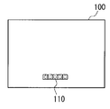
- FIG. 2 is a front view of the radio wave sensor according to the embodiment.
- FIG. 2 is a side view of the radio wave sensor according to the embodiment.
- FIG. 2 is a rear view of the radio wave sensor according to the embodiment.
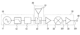
- FIG. 3 is a functional configuration diagram of a sensor module.
- FIG. 4 is an exemplary diagram of a waveform of a detection signal after homodyne detection by a mixer.
- FIG. 3 is a detailed configuration diagram of an antenna unit.
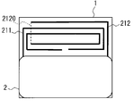
- FIG. 3 is a front view of a mounted state of the sensor module.
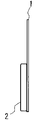
- FIG. 4 is a side sectional view of a mounted state of the sensor module.
- the rear view of the mounting state of a sensor module The figure which shows the directivity example of a radio wave type sensor.
- FIG. 3 is a functional configuration diagram of a sensor module.
- FIG. 4 is an exemplary diagram of a waveform of a detection signal after homodyne detection by a mixer.
- FIG. 3 is a detailed configuration
- FIG. 3 is an explanatory diagram of a horizontal plane and a vertical plane of the radio wave sensor.
- FIG. 4 is an explanatory diagram of movement of a hand as an object. Explanatory drawing of the input-output relationship of an active filter.
- FIG. 3 is an explanatory diagram of a detection signal and a waveform of a detection signal.
- FIG. 7 is a waveform comparison diagram of a detection signal when an active filter is not provided and when an active filter is provided.
- FIG. 4 is an explanatory diagram of a change point of a signal level in a detection signal.
- FIG. 9 is a functional configuration diagram of a sensor module according to a modification.
- a radio wave sensor is a sensor that uses radio waves for detecting the presence, position, movement, and the like of an object, and has an advantage that it is hardly influenced by an environment such as heat, light, and wind that does not hinder radio wave propagation.
- water acts as a dielectric in both the solid and liquid phases, for example, rain, fog, snow, water drops, ice (hereinafter collectively referred to as "water"), etc. act as a dielectric. Therefore, if these are present between the target and the case of the radio wave sensor, in particular, depending on the frequency of the signal used, the propagation loss increases, and the target may not be detected correctly.
- radio wave sensors are mainly used in the quasi-millimeter wave band and the millimeter wave band such as the 10.5 GHz band, 24 GHz band, and 79 GHz band.
- the millimeter wave band such as the 10.5 GHz band, 24 GHz band, and 79 GHz band.
- radio waves are hardly transmitted due to the influence of water.
- it is necessary to take measures such as applying a water-repellent treatment to the case surface of the radio wave sensor and incorporating a heater to prevent dew condensation and the like.
- the operating frequency is reduced, the propagation loss of radio waves due to water is reduced.
- the wavelength ⁇ becomes longer, so that the size of the antenna element increases and the detection accuracy also decreases. Therefore, in the present embodiment, an example of a radio wave sensor that is not affected by environmental influences of water without increasing the size of the antenna element will be described.
- the radio wave sensor according to the present embodiment is configured by housing a sensor module described later in a box-shaped case 100.
- 1A is a front view of the radio wave sensor (case 100)
- FIG. 1B is a side view
- FIG. 1C is a rear view.
- the case 100 is made of a resin having a long side W of 40 mm, a short side D of 20 mm, and a height H1 of 5.0 mm, and has a rear surface for electrical connection with a circuit on an electronic device side equipped with a radio wave sensor.
- Connector 110 is provided. In the connector 110, an enable pin, a power supply Vcc pin, an output pin described later, and two GND (ground) pins are arranged at a pitch of approximately 2 mm.
- the height H2 considering the end of the connector is about 9.5 mm, which is sufficiently smaller than a general radio wave sensor using a millimeter wave band.
- a cable output may be obtained by connecting a multi-core cable instead of the connector 110.
- FIG. 2 is a functional configuration diagram of the sensor module housed in the case 100.
- the sensor module has a transmitting unit 10, an antenna unit 20, and a receiving unit 30.
- the transmission unit 10 is configured by cascade-connecting an oscillator 11, a filter 12, and a variable attenuator 13.
- the oscillator 11 oscillates a transmission signal of 300 MHz (actually, there is a fluctuation of about 5 MHz with respect to 300 MHz). This transmission signal is a continuous wave.
- the use of the 300 MHz oscillator 11 is a general-purpose product used in portable communication devices, keyless entries, wireless microphones, ham radios, etc., there are many types of semiconductors that can be used, design is easy, and cost is low. But it is advantageous.
- the filter 12 removes a harmonic component of the transmission signal.
- the variable attenuator 13 adjusts the output level of the transmission signal that has passed through the filter 12 to a weak power that is not restricted by the Radio Law, for example, ⁇ 45 dBm or less, and outputs it to the antenna unit 20.
- the antenna unit 20 is an integrated antenna element 21 and distributor 22. This will be described in detail later.
- Distributor 22 outputs the transmission signal from transmitting section 10 to antenna element 21 and also outputs to receiving section 30.
- the distributor 22 outputs a reflection signal from the object received by the antenna element 21 to the receiving unit 30.
- the receiving unit 30 includes an amplifier 31, a mixer 32, and an active filter 33.
- the amplifier 31 receives the transmission signal and the reflection signal from the transmission unit 10, amplifies each signal, and outputs the amplified signal to the mixer 32.
- the amplifier 31 is a low-noise high-frequency amplifier capable of amplifying a signal in the 300 MHz band.
- the mixer 32 outputs a detection signal 321 by performing homodyne detection using a transmission signal as a local (reference signal) and a reflected signal as a reference signal.
- the mixer 32 is generally composed of a diode, but may be a circuit having an amplification factor (gain) using bipolar transistors.
- FIG. 3 shows a waveform example of the detection signal 321.
- the detection signal 321 is a Doppler signal in which the Doppler effect caused by the movement of the target object has appeared.
- the Doppler effect appears as a frequency component of a change point (displacement portion) 3211 at the time when the signal level changes. This frequency component is in a predetermined frequency band lower than the transmission signal (300 MHz) and determined according to the application.
- the detection signal 321 output from the mixer 32 is input to the active filter 33.
- the active filter 33 is formed of a semiconductor, extracts a signal in a predetermined frequency band at the time when the signal level of the Doppler signal changes from the detection signal 321 by passing through a band-pass filter, for example, and amplifies the signal to a predetermined signal level.
- the detection signal 331 is output to the output pin 40.
- an operational amplifier differential amplifier
- an amplifier low-frequency amplifier
- a passive filter may be combined. As a result of experiments by the present inventor, it has been confirmed that about 5 Hz to 15 Hz is most suitable for moving object detection in a predetermined frequency band.
- the Doppler effect is obtained by detecting an entire sine wave of one or more periods of the Doppler signal. Therefore, in order to detect the movement of the object based on the Doppler signal, the condition is that the object moves by a distance of at least one wavelength (about 1 m at 300 MHz) of the transmission signal. Therefore, if the moving distance of the object is shorter than the wavelength of the transmission signal, the Doppler signal cannot be detected accurately.
- the sensor module of the present embodiment only the frequency component of the signal level change point 3211 which is a part of the entire waveform of the Doppler signal is extracted.
- the movement is not necessary to detect the entire waveform of the Doppler signal, and it is possible to detect even a movement in which the moving distance of the object is short with respect to one wavelength (about 1 m in this example) of the transmission signal. For example, even if the movement distance is about 15 cm, the movement can be detected.
- the detection of the movement of the object can be realized by, for example, converting the detection signal 331 into a digital signal by an analog-to-digital converter and performing a detection process on the converted detection signal 331 by, for example, a DSP (digital signal processor).
- a DSP digital signal processor
- the analog-to-digital converter and the DSP are assumed to be provided as a subsequent circuit that is electrically connected to the output pin 40 of the connector 110.
- the analog-digital converter and the DSP are inserted between the active filter 33 and the output pin 40. Is also good.
- FIG. 4 is a detailed configuration diagram of the antenna unit 20.
- 5A is a front view of a mounted state of the sensor module
- FIG. 5B is a sectional side view
- FIG. 5C is a rear view.
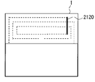
- the antenna element 21 of the antenna unit 20 is configured such that a transmission element 211 and a reception element 212 formed of conductive patterns are respectively arranged close to each other on a single plane, for example, on an upper exposed portion of the printed circuit board 1.
- FR (Flame Retardant Type) -4 having a thickness of 0.6 mm can be used.
- the components of the transmitting unit 10 and the receiving unit 30 described above are mounted on a portion other than the antenna element 21 of the printed circuit board 1.
- the printed circuit board 1 has front and back surfaces, and the components of the transmission unit 10 and the reception unit 30 are mounted on one surface, for example, the front surface, and then loaded with the shield case 2 to be affected by external noise. I do not have it.
- the transmitting element 211 and the receiving element 212 preferably have a shape in which a part includes a curve or a corner.
- the angle of the corner can be, for example, 90 degrees.
- the transmitting element 211 and the receiving element 212 have a shape having a plurality of 90-degree corners or a meander mosaic shape. The gaps formed by these corners in one element are arranged such that the other elements do not cross each other in the same plane.
- the receiving element 212 is formed on the front surface of the printed circuit board 1, and the linear portion 2120 which is a part of the receiving element 212 is formed on the back surface side of the printed circuit board 1 so as not to cross the transmitting element 211. Is done. Other parts of the receiving element 212 are formed on the front side of the printed circuit board 1.
- the straight portion 2120 formed on the back surface side of the receiving element 212 and other portions formed on the front surface side can be electrically connected by a via hole or the like.
- the tips 2111, 121 of the transmitting element 211 and the receiving element 212 are formed to face each other at a predetermined interval. Therefore, the transmission element 211 and the reception element 212 are electrically coupled to each other. The coupling degree can be adjusted by the interval P.
- the distributor 22 is integrated with the antenna element 21. That is, the transmission signal S211 input from the input unit IN of the antenna unit 20 is radiated from the transmission element 211 toward the target, but a part of the transmission signal S211 is transmitted to the reception element 212 by electrical coupling, and OUT is reached. The reflected signal S212 received by the receiving element 212 also reaches the output unit OUT. As described above, since there is no need to separately provide the distributor 22, the size of the antenna unit 20 can be reduced, and the configuration can be simplified.
- the transmitting element and the receiving element are not shared, but are separated from each other, so that it is possible to set antenna characteristics differently.
- the radiation efficiency of the transmission element 211 is reduced to reduce the effective radiation power, while the radiation efficiency of the reception element 212 is increased in order to improve the detection performance. It can respond to the demand for increasing the size.
- the length of the transmitting element 211 is L1 and the length of the receiving element 212 is L2, it is desirable that L1 ⁇ L2 from the viewpoint of radiation efficiency.
- the entire length (L1 + L2) of the antenna element 21 is set to approximately 1 / or ⁇ ⁇ of the wavelength ⁇ of the transmission signal (the same applies to the reflection signal).
- the length L1 of the transmission element 211 is set to approximately 8 ⁇
- the length L2 of the reception element 212 is set to approximately 4 ⁇ .
- L1 was 65 mm
- L2 was 142 mm
- the pattern width W was 0.2 mm
- the element interval P was 1 mm.
- the tip 2111 of the transmitting element 211 and the tip 2121 of the receiving element 212 are separated from each other is that when they are connected, they operate as a loop-shaped element.
- the length of the wavelength ⁇ is required as the entire length, and a large area is required. Therefore, such an operation mode is avoided.
- FIG. 6A is a graph showing an example of directivity characteristics of the antenna element 21 when the wide surface (the front surface and the back surface) of the case 100 of the radio wave sensor is installed horizontally with respect to the ground.
- 0 degree is an angle vertically above the wide surface of the case 100
- 180 degrees is an angle vertically below the wide surface of the case 100, as shown in FIG. 6B.
- 90 degrees and ⁇ 90 degrees are angles parallel to the wide surface of the case 100, and a plane including both angles is a horizontal plane H.
- a broken line 62 is a pattern indicating the directivity of the horizontal plane H
- a solid line 61 is a pattern indicating the directivity of the vertical plane V.
- FIG. 7A shows a state where the detection signal 321 at this time is input to the active filter 33 and the detection signal 331 is output.
- FIG. 7C shows waveform examples of the detection signal 321 and the detection signal 331 on the same scale.
- the vertical axis in FIG. 7C is the amplitude of the signal component, and the horizontal axis is time.
- the detection signal 321 is a Doppler signal including 15 Hz which is a frequency component of a signal level change point, and has a frequency of 300 MHz.
- the detection signal 331 is obtained by extracting and amplifying only the frequency component of 15 Hz from the detection signal 321 and has a waveform that accurately captures the hand movement.
- a signal waveform 322 when the detection signal 321 is simply amplified without using the active filter 33 is shown in the upper part of FIG. 8 is the waveform of the detection signal 331 in the lower part of FIG. 7C.
- the vertical axis in FIG. 8 is the amplitude of the signal component, and the horizontal axis is time.
- the active filter 33 when the active filter 33 is not used, as shown in the upper waveform of FIG. 8, since there are many noises and a large number of frequency components are superimposed, it is difficult to identify a hand movement. However, by using the active filter 33, it can be seen that the waveform-formed detection signal 331 is output.
- the change point of the signal level of the detection signal 321 is a first change point (rising) 3211 at which movement starts from normal and a second change point (at which movement stops and returns to normal). (Fall) 3212.
- the former is the same as the change point 3211 shown in FIG. 3, and the description so far relates to an example in which only the frequency component at the first change point 3211 is extracted.
- only the second change point 3212, or one of the first change point 3211 and the second change point 3212, which is easily extracted, or both frequency components may be extracted.
- ⁇ Effects of Embodiment> since the Doppler effect of the 300 MHz band radio wave is used, a conventional radio wave sensor using a millimeter wave or a quasi-millimeter wave, or an infrared sensor, a capacitance sensor, or an image sensor It is less susceptible to the presence of water and mud as compared to. Therefore, for example, the object can be detected not only as a sensor for automatically opening and closing the door of a vehicle in a cold region specification, but also in a state buried in water or in snow.
- the reflected signal acquired by the antenna unit 20 is homodyne-detected with a transmission signal to output a detection signal 321 that is a Doppler signal, and a first change point 3211 of the signal level of the detection signal 321 is detected.
- a signal component of a predetermined frequency band for example, about 5 Hz to 15 Hz is extracted from the detected first change point 3211 and the presence or absence of the object or its movement is detected, so that even a small movement of the object can be detected.
- power consumption is significantly reduced as compared with a magnetic sensor or the like.
- the radio wave sensor according to the present embodiment operates with a power supply of, for example, 3 V and consumes about 10 mA, so that it can be operated with, for example, a general-purpose dry battery.
- the detection range the detection distance can be made longer than that of the capacitance type sensor or the magnetic type sensor.
- the voltage and power consumption are small, in many countries there is no need to obtain a license to use the radio wave sensor of this embodiment. Can be.
- the antenna element 21 of the antenna unit 20 can be configured such that the transmission element 211 and the reception element 212 are separated from each other, and each antenna characteristic can be set independently. Therefore, the entire antenna characteristics can be flexibly changed according to the application, such as easy sensing suitable for short-range communication using weak power.
- the antenna element 21 is composed of the transmission element 211 and the reception element 212, and the two elements 211 and 212 are arranged close to each other to be electrically coupled, thereby making the distributor 22
- the antenna element of the sensor module has been described as an example in which is integrated with the antenna element 21.
- embodiments of the present invention are not limited to such an embodiment.
- FIG. 10 is a functional configuration diagram of the sensor module in this case. For convenience, components having the same functions as those of the sensor module shown in FIG. 2 are denoted by the same reference numerals.
- the distributor 22 is provided between the transmission element 211 and the variable attenuator 13.
- the transmission signal for homodyne detection is distributed by the distributor 22, amplified by the amplifier 41, and supplied to the mixer 32.
- the active filter 33 operates in the same manner as in the present embodiment, the active filter 33 is less likely to be affected by the environment due to water and can detect small movements of the object.
- an example in which a general-purpose oscillator in the 300 MHz band is used as the oscillator 11 has been described, but an oscillator in a lower frequency band may be used as long as the radio wave has a frequency that allows water to pass through. It does not preclude the use of oscillators in the frequency band below the quasi-millimeter wave band.
Landscapes
- Engineering & Computer Science (AREA)
- Remote Sensing (AREA)
- Radar, Positioning & Navigation (AREA)
- Physics & Mathematics (AREA)
- General Physics & Mathematics (AREA)
- Computer Networks & Wireless Communication (AREA)
- Life Sciences & Earth Sciences (AREA)
- Geology (AREA)
- General Life Sciences & Earth Sciences (AREA)
- Geophysics (AREA)
- Environmental & Geological Engineering (AREA)
- Electromagnetism (AREA)
- Radar Systems Or Details Thereof (AREA)
- Geophysics And Detection Of Objects (AREA)
- Details Of Aerials (AREA)
Abstract
熱、光、降雨、降雪、風などの環境に左右されにくく、簡素な構造で小型・低消費を実現したセンサを提供する。アンテナ部は、水を透過する周波数帯、例えば300MHz帯の送信信号を放射するとともに、放射された送信信号が対象物で反射された反射信号を送信信号と共に受信する。受信部は、反射信号を送信信号でホモダイン検波して信号レベルの変化点を検出し、この変化点から約5~15Hzの信号成分を抽出し、これにより対象物の有無又は対象物の動きを検知する。
Description
本発明は、近距離に存在する対象物の動きを検知可能な電波式センサに関する。
数10cm~数mの動体を検出する近距離用動体検知センサが知られている。近距離用動体検知センサは、近年、低コスト、省電力、小型化が進んでおり、それを搭載した電子機器の利便性の拡大が期待されている。例えば特許文献1には、車両に近づいた運転者の動きを検知してその車両のドア開閉を自動で行う制御装置が開示されている。特許文献1に開示された制御装置は、車両のドア付近に設けられた近距離用動体検知センサで運転者の有無及び動作を検出する。そして、ドアが作動中か否かを判定し、判定結果に基づいてドアの開閉制御を行っている。
特許文献1に開示された制御装置は、車両に取り付けられるので、近距離用動作検知センサのケースに水、氷、雪、泥などが付着することがある。また、水アカが堆積したり、水アカが膜化することがある。そのため、動体を検知する感度が低下して、制御装置が正しく動作しない場合がある。このような現象は、赤外線式センサ、静電容量式センサ、画像式のセンサなど、非接触型のセンサにおいても同様に生じる。
本発明は、環境影響に左右されにくく、簡素な構造で小型・低消費電力を実現したセンサを提供することを主たる課題とする。
本発明は、例えば水(水分を含む物質を含む)を透過する周波数帯の電波を使用する電波式センサに適用することで、上記課題を解決する。この電波式センサは、準ミリ波帯未満の周波数帯の送信信号を放射し、かつ、放射された前記送信信号が対象物で反射された反射信号と、前記送信信号と、を受信するアンテナ部と、前記アンテナ部で受信した前記反射信号を前記送信信号でホモダイン検波して信号レベルの変化点を検出する検出部と、前記検出部で検出された前記変化点から前記送信信号の周波数帯よりも低い所定周波数帯の信号成分を抽出し、これにより前記対象物の有無又は前記対象物の動きを検知する検知部と、を有する。
本発明によれば、環境影響に左右されにくく、簡素な構造で小型・低消費電力を実現したセンサを提供することができる。
以下、図面を参照して本発明の実施の形態例を説明する。本実施形態では、本発明を電波式センサに適用した場合の例を示す。電波式センサは、対象物の有無、位置、動きなどの検知に電波を用いるセンサであり、熱、光、風など、電波伝搬に支障が生じない環境の影響に左右されにくいという利点がある。しかし、水は固相でも液相でも誘電体として作用するため、例えば雨、霧、雪、水滴、氷(以下、「水」と総称)などは誘電体として作用する。従って、これらが対象物との間に存在し、特に電波式センサのケースに付着すると、使用する信号の周波数によっては、伝搬損失が大きくなり、対象物を正しく検知できない場合がある。
電波式センサは、小型化並びに十分な検出精度を確保する観点から10.5GHz帯、24GHz帯、79GHz帯などの準ミリ波帯及びミリ波帯で使用するものが主流であるが、このような高い周波数帯では、水の影響により、電波が透過しにくくなる。そのため、電波式センサのケース表面に撥水加工を施す、ヒーターを内蔵して結露等を防ぐ等の対応が必要となる。使用周波数を低くすれば、水による電波の伝搬損失は小さくなる。しかし、使用周波数を低くすると、波長λが長くなるので、アンテナ素子のサイズが大きくなり、検出精度も低くなる。
そこで、本実施形態では、アンテナ素子のサイズを大きくすることなく、水による環境影響にも左右されない電波式センサの例を説明する。
そこで、本実施形態では、アンテナ素子のサイズを大きくすることなく、水による環境影響にも左右されない電波式センサの例を説明する。
本実施形態の電波式センサは、箱状のケース100に、後述するセンサモジュールを収容して構成される。図1Aは電波式センサ(ケース100)の正面図、図1Bは側面図、図1Cは背面図である。
ケース100は、長辺Wが40mm、短辺Dが20mm、高さH1が5.0mmの樹脂製であり、背面には、電波式センサを搭載する電子機器側の回路との電気的接続用のコネクタ110が設けられている。コネクタ110は、イネーブルピン、電源Vccピン、後述する出力ピン、二つのGND(接地)ピンが、ほぼ2mmピッチで配置されている。イネーブルピンが論理Highでセンサモジュールが動作し、論理Lowでスタンバイとなる。コネクタの先端までを考慮した高さH2は約9.5mmであり、ミリ波帯を用いた一般的な電波式センサよりも十分小型である。
このような端子出力のほか、コネクタ110の代わりに多芯ケーブルを接続してケーブル出力としても良い。
ケース100は、長辺Wが40mm、短辺Dが20mm、高さH1が5.0mmの樹脂製であり、背面には、電波式センサを搭載する電子機器側の回路との電気的接続用のコネクタ110が設けられている。コネクタ110は、イネーブルピン、電源Vccピン、後述する出力ピン、二つのGND(接地)ピンが、ほぼ2mmピッチで配置されている。イネーブルピンが論理Highでセンサモジュールが動作し、論理Lowでスタンバイとなる。コネクタの先端までを考慮した高さH2は約9.5mmであり、ミリ波帯を用いた一般的な電波式センサよりも十分小型である。
このような端子出力のほか、コネクタ110の代わりに多芯ケーブルを接続してケーブル出力としても良い。
図2は、ケース100に収容されるセンサモジュールの機能構成図である。センサモジュールは、送信部10、アンテナ部20及び受信部30を有する。送信部10は、発振器11、フィルタ12及び可変減衰器13を縦列接続して構成される。発振器11は300MHz(実際には300MHzに対して5MHz程度の変動がある)の送信信号を発振する。この送信信号は連続波である。
300MHzの発振器11を用いるのは、それが携帯通信機、キーレスエントリー、ワイヤレスマイク、アマチュア無線などで使用される汎用品であり、使用できる半導体の種類が多く、設計が容易になるほか、コスト面でも有利だからである。
300MHzの発振器11を用いるのは、それが携帯通信機、キーレスエントリー、ワイヤレスマイク、アマチュア無線などで使用される汎用品であり、使用できる半導体の種類が多く、設計が容易になるほか、コスト面でも有利だからである。
フィルタ12は、送信信号の高調波成分を除去する。可変減衰器13は、フィルタ12を通過した送信信号の出力レベルを電波法による制限のない微弱電力、例えば-45dBm以下に調整してアンテナ部20へ出力する。
アンテナ部20は、アンテナ素子21と分配器22とを一体化したものである。これについては後で詳しく説明する。分配器22は、送信部10からの送信信号をアンテナ素子21へ出力するとともに、受信部30へも出力する。また、分配器22は、アンテナ素子21で受信した対象物からの反射信号を受信部30へ出力する。
受信部30は、増幅器31、ミキサ32及びアクティブフィルタ33を有する。増幅器31は、送信部10からの送信信号と反射信号とが入力され、それぞれの信号を増幅してミキサ32へ出力する。増幅器31は、300MHz帯の信号を増幅可能な低ノイズ高周波増幅器である。
ミキサ32は、送信信号をローカル(基準信号)、反射信号を対照信号としてホモダイン検波することにより、検波信号321を出力する。ミキサ32は、一般的にはダイオードで構成されるが、バイポーラトランジスタを使って増幅度(利得)を有する回路とすることもできる。
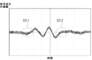
検波信号321の波形例を図3に示す。検波信号321は、対象物の動きに起因するドップラー効果が表れたドップラー信号となる。ドップラー効果は、信号レベルが変化した時点の変化点(変位部)3211の周波数成分として表れる。この周波数成分は、送信信号(300MHz)よりも低い、用途に応じて定めた所定周波数帯のものとなる。
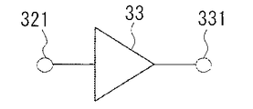
ミキサ32から出力される検波信号321は、アクティブフィルタ33に入力される。アクティブフィルタ33は半導体で構成され、検波信号321からドップラー信号の信号レベルが変化した時点の所定周波数帯の信号を例えば帯域通過フィルタを通過させることで抽出し、所定の信号レベルに増幅した後、検出信号331として出力ピン40へ出力する。
半導体にはオペアンプ(差動増幅器)を使用することができるが、増幅器(低周波増幅器)とパッシブフィルタを組み合わせて構成しても良い。所定の周波数帯は、本発明者の実験の結果、約5Hz~15Hzが最も動体検出に適していたことを確認している。
半導体にはオペアンプ(差動増幅器)を使用することができるが、増幅器(低周波増幅器)とパッシブフィルタを組み合わせて構成しても良い。所定の周波数帯は、本発明者の実験の結果、約5Hz~15Hzが最も動体検出に適していたことを確認している。
一般に、ドップラー効果は、ドップラー信号の一周期以上の正弦波の全体波形を検波することで得られる。従って、ドップラー信号を基に対象物の動きを検知しようとする場合、対象物が送信信号の1波長以上の距離(300MHzでは約1m)以上移動することが条件となる。そのため、対象物の移動距離が送信信号の波長より短いと、ドップラー信号を正確に検知することができない。
これに対して、本実施形態のセンサモジュールでは、ドップラー信号の全体波形の一部である信号レベルの変化点3211の周波数成分だけを抽出する。そのため、ドップラー信号の全体波形を検波する必要がなく、送信信号の1波長(本例では約1m)に対して対象物の移動距離が短い動きであっても検知可能となる。例えば15cm程度の移動距離であってもその動きを検知することができる。
これに対して、本実施形態のセンサモジュールでは、ドップラー信号の全体波形の一部である信号レベルの変化点3211の周波数成分だけを抽出する。そのため、ドップラー信号の全体波形を検波する必要がなく、送信信号の1波長(本例では約1m)に対して対象物の移動距離が短い動きであっても検知可能となる。例えば15cm程度の移動距離であってもその動きを検知することができる。
対象物の動きの検知は、例えば、検出信号331をアナログ・デジタル変換器でデジタル信号に変換し、変換後の検出信号331を例えばDSP(digital signal processor)で検知処理を行うことにより実現可能である。アナログ・デジタル変換器及びDSPは、本例では、コネクタ110のうち出力ピン40と導通する後段回路として備えることを想定しているが、アクティブフィルタ33と出力ピン40との間に介挿させても良い。
次に、アンテナ部20について詳しく説明する。図4は、アンテナ部20の詳細構成図である。また、図5Aはセンサモジュールの実装状態の正面図、図5Bは側部断面図、図5Cは背面図である。アンテナ部20のアンテナ素子21は、一つの平面上、例えばプリント基板1の上部露出部位に、それぞれ導電パターンで形成された送信エレメント211と受信エレメント212とをそれぞれ近接させて配置したものである。
プリント基板1には、厚み0.6mmのFR(Flame Retardant Type)-4を用いることができる。プリント基板1のアンテナ素子21以外の部位には、上記の送信部10及び受信部30の構成部品が実装されている。プリント基板1は表裏面を有し、送信部10及び受信部30の構成部品は、その一方の面、例えば表面に実装された後、シールドケース2を装荷して外来からのノイズの影響を受けないようにしてある。
送信エレメント211と受信エレメント212は、実装状態では、好ましくは、その一部がカーブあるいはコーナーを含む形状を有する。カーブの曲率やコーナーの角度に特段の制限はない。コーナーの角度は例えば90度とすることができる。本実施形態では、図5A,図5Bに示されるように、送信エレメント211と受信エレメント212とは、90度のコーナーを複数有する形状、あるいはメアンダモザイク(meander mosaic)形状を有する。一方のエレメントにおいてこれらのコーナーによって形成される間隙部分に、他方のエレメントが同じ面内では互いに交差しないように配置される。図示されるように、受信エレメント212は、プリント基板1の表面に形成され、受信エレメント212の一部である直線部2120は、送信エレメント211と交差しないように、プリント基板1の裏面側に形成される。受信エレメント212のその他の部分は、プリント基板1の表面側に形成される。受信エレメント212の裏面側に形成された直線部2120と、表面側に形成されたその他の部分とは、ビアホールなどで導通が可能である。
送信エレメント211と受信エレメント212の各々の先端2111,2121は、所定間隔で向き合うように形成される。そのため、送信エレメント211と受信エレメント212とが互いに電気的に結合する。結合度は、間隔Pにより調整することができる。これにより、上記の分配器22がアンテナ素子21と一体化する。すなわち、アンテナ部20の入力部INから入力された送信信号S211は、送信エレメント211から対象物に向けて放射されるが、電気的な結合によりその一部が受信エレメント212に伝達され、出力部OUTに到達する。出力部OUTには、受信エレメント212で受信された反射信号S212も到達する。このように、分配器22を別途設ける必要がないため、アンテナ部20の小型化が可能になり、構成も簡略化される。
送信エレメント211と受信エレメント212の各々の先端2111,2121は、所定間隔で向き合うように形成される。そのため、送信エレメント211と受信エレメント212とが互いに電気的に結合する。結合度は、間隔Pにより調整することができる。これにより、上記の分配器22がアンテナ素子21と一体化する。すなわち、アンテナ部20の入力部INから入力された送信信号S211は、送信エレメント211から対象物に向けて放射されるが、電気的な結合によりその一部が受信エレメント212に伝達され、出力部OUTに到達する。出力部OUTには、受信エレメント212で受信された反射信号S212も到達する。このように、分配器22を別途設ける必要がないため、アンテナ部20の小型化が可能になり、構成も簡略化される。
本実施形態では、送信エレメントと受信エレメントとを共用にするのではなく、これらを別体にすることで、アンテナ特性を異なるものに設定することも可能であるという効用がある。例えば、微弱電波を用いた近距離通信を実現するために、送信エレメント211については放射効率を低くして実効輻射電力を小さくする一方、受信エレメント212については、検出性能を高めるために放射効率を大きくするという需要に対応することができる。
この場合、送信エレメント211の長さをL1、受信エレメント212の長さをL2とすると、放射効率の観点からはL1<L2にすることが望ましい。また、アンテナ素子21の全体の長さ(L1+L2)は、送信信号(反射信号も同様)の波長λの略1/4又は略3/8にする。一例では、送信エレメント211の長さL1は略1/8λ、受信エレメント212の長さL2は略1/4λに設定される。本例では、L1を65mm、L2を142mm、パターン幅Wを0.2mm、エレメント間隔Pを1mmとし、プリント基板1の上半分の表裏面に配置した。
この場合、送信エレメント211の長さをL1、受信エレメント212の長さをL2とすると、放射効率の観点からはL1<L2にすることが望ましい。また、アンテナ素子21の全体の長さ(L1+L2)は、送信信号(反射信号も同様)の波長λの略1/4又は略3/8にする。一例では、送信エレメント211の長さL1は略1/8λ、受信エレメント212の長さL2は略1/4λに設定される。本例では、L1を65mm、L2を142mm、パターン幅Wを0.2mm、エレメント間隔Pを1mmとし、プリント基板1の上半分の表裏面に配置した。
送信エレメント211の先端2111と受信エレメント212の先端2121とを離間させているのは、両者を連結させるとループ状エレメントとして動作するためである。このような動作を容認する場合、全体の長さとして波長λの長さが必要となり、大きな面積を要することになるため、このような動作態様を回避したものである。
図6Aは、電波式センサのケース100の幅広面(表面及び背面)を大地に対して水平に設置したときのアンテナ素子21の指向特性例を示すグラフである。このグラフにおいて0度は、図6Bに示すように、ケース100の幅広面に対して鉛直上方の角度、180度は鉛直下方の角度であり、両方の角度を含む面が垂直面Vとなる。また、90度及び-90度は、ケース100の幅広面と平行の角度であり、両方の角度を含む面が水平面Hとなる。図6Aのグラフにおいて、破線62は水平面Hの指向特性を示すパターン、実線61は垂直面Vの指向特性を示すパターンとなる。
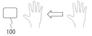
次に、本実施形態の電波式センサの動作例について説明する。ここでは、図7Aに示すように、使用者の手がケース100の15cm上を横切る動きをしたものとする。図7Bはこのときの検波信号321がアクティブフィルタ33に入力され、検出信号331が出力される状態を示す。この検波信号321と検出信号331の波形例を同じスケールで示したのが図7Cである。図7Cの縦軸は信号成分の振幅、横軸は時間である。
検波信号321は、信号レベルの変化点の周波数成分である15Hzを含むドップラー信号であるが、周波数は300MHzである。これに対して、検出信号331は、検波信号321から15Hzの周波数成分だけを抽出して増幅したものであり、手の動きを忠実に捉えた波形となっている。便宜上、検波信号321をアクティブフィルタ33によらず、単純に増幅したときの信号波形322を図8上段に示す。図8の下段波形は図7C下段の検出信号331の波形である。図8の縦軸は信号成分の振幅、横軸は時間である。
このように、アクティブフィルタ33を用いない場合は、図8上段波形に示されるように、ノイズが多く、多数の周波数成分が重畳されているので、手の動きを識別するのが困難となる。しかし、アクティブフィルタ33を用いることにより、波形成形された検出信号331が出力されることがわかる。
このように、アクティブフィルタ33を用いない場合は、図8上段波形に示されるように、ノイズが多く、多数の周波数成分が重畳されているので、手の動きを識別するのが困難となる。しかし、アクティブフィルタ33を用いることにより、波形成形された検出信号331が出力されることがわかる。
検波信号321(ドップラー信号)の信号レベルの変化点は、図9に示すように、平常時から動きが始まる第1変化点(立ち上がり)3211と、動きが止んで平常時に戻る第2変化点(立ち下がり)3212とがある。前者は、図3に示した変化点3211と同じであり、これまでの説明は、この第1変化点3211における周波数成分だけを抽出する例に関する。しかし、第2変化点3212だけ、あるいは第1変化点3211と第2変化点3212のうち抽出容易な一方、あるいは、双方の周波数成分を抽出するようにしても良い。
<実施形態の効果>
以上の通り、本実施形態では、300MHz帯の電波によるドップラー効果を利用するので、ミリ波又は準ミリ波を用いた従来の電波式センサ、あるいは、赤外線式、静電容量式、画像式のセンサに比べて水や泥の有無などに左右されにくくなる。そのため、例えば寒冷地仕様車両のドアの自動開閉用のセンサとしての用途はもとより、水中あるいは雪の中に埋没した状態でも対象物を検知することができる。また、汚れなどによるケース100などのメンテナンス(清掃)なども不要となるため、従来使用が難しかった屋外や水回り場所、露や霜などが付く保管庫などに設置することができ、センサやセンサ搭載機器の多様化や小型化、省電力化に貢献することができる。
以上の通り、本実施形態では、300MHz帯の電波によるドップラー効果を利用するので、ミリ波又は準ミリ波を用いた従来の電波式センサ、あるいは、赤外線式、静電容量式、画像式のセンサに比べて水や泥の有無などに左右されにくくなる。そのため、例えば寒冷地仕様車両のドアの自動開閉用のセンサとしての用途はもとより、水中あるいは雪の中に埋没した状態でも対象物を検知することができる。また、汚れなどによるケース100などのメンテナンス(清掃)なども不要となるため、従来使用が難しかった屋外や水回り場所、露や霜などが付く保管庫などに設置することができ、センサやセンサ搭載機器の多様化や小型化、省電力化に貢献することができる。
また、エレメント間の電気的な結合を利用することで分配器22をアンテナ素子21と一体化させることにより、電波式センサの小型化、構成の簡素化に寄与することができる。
本実施形態では、また、アンテナ部20で取得した反射信号を送信信号でホモダイン検波してドップラー信号である検波信号321を出力し、この検波信号321の信号レベルの第1変化点3211を検出する。更に、検出された第1変化点3211から所定周波数帯、例えば約5Hz~15Hzの信号成分を抽出し、これにより対象物の有無又はその動きを検知するので、対象物の小さな動きでも検出が可能となる。
例えば磁気式センサなどに比べて消費電力も大幅に低下する。本実施形態の電波式センサは、例えば3Vの電源で動作し、電力消費も10mA程度なので、例えば汎用の乾電池で動作させることもできる。検出範囲も、静電容量式センサや磁気式センサに比べ検出距離を大きくとることができる。また、電圧及び消費電力が小さいことから、多くの国においては本実施形態の電波式センサを使用するためにライセンスを取得する必要がないので、搭載機器の種類や用途制限なく安心して使用することができる。
例えば磁気式センサなどに比べて消費電力も大幅に低下する。本実施形態の電波式センサは、例えば3Vの電源で動作し、電力消費も10mA程度なので、例えば汎用の乾電池で動作させることもできる。検出範囲も、静電容量式センサや磁気式センサに比べ検出距離を大きくとることができる。また、電圧及び消費電力が小さいことから、多くの国においては本実施形態の電波式センサを使用するためにライセンスを取得する必要がないので、搭載機器の種類や用途制限なく安心して使用することができる。
本実施形態では、また、アンテナ部20のアンテナ素子21を、送信エレメント211と受信エレメント212とを別体とし、それぞれのアンテナ特性を独自に設定することができる。従って、微弱な電力を用いた近距離通信に適したセンシングが容易になるなど、全体のアンテナ特性を用途に応じてフレキシブルに変更することができる。
<変形例>
本実施形態では、センサモジュールのうち、アンテナ素子21を送信エレメント211と受信エレメント212とで構成し、両エレメント211、212を近接して配置することで電気的に結合させ、これにより分配器22をアンテナ素子21と一体化した場合の例を説明した。しかし、本発明の実施の態様は、このような形態に限定されるものではない。例えば、センサモジュールのアンテナ素子を、送信系と受信系とに物理的に離間して配置することも可能である。
図10はこの場合のセンサモジュールの機能構成図である。便宜上、図2に示したセンサモジュールと同機能の構成部品については同じ符号を付してある。
本実施形態では、センサモジュールのうち、アンテナ素子21を送信エレメント211と受信エレメント212とで構成し、両エレメント211、212を近接して配置することで電気的に結合させ、これにより分配器22をアンテナ素子21と一体化した場合の例を説明した。しかし、本発明の実施の態様は、このような形態に限定されるものではない。例えば、センサモジュールのアンテナ素子を、送信系と受信系とに物理的に離間して配置することも可能である。
図10はこの場合のセンサモジュールの機能構成図である。便宜上、図2に示したセンサモジュールと同機能の構成部品については同じ符号を付してある。
図10に示すセンサモジュールでは、分配器22を、送信エレメント211と可変減衰器13との間に設ける。また、ホモダイン検波用の送信信号は、この分配器22で分配し、増幅器41で増幅した後にミキサ32へ供給する。このような構成でも、アクティブフィルタ33は、本実施形態と同様に動作するので、水による環境影響を受けにくく、かつ、対象物の小さな動きを検知することができる。
本実施形態では、発振器11として、汎用品である300MHz帯の発振器を使用した例について説明したが、水を透過する周波数の電波であれば、それ以下の周波数帯の発振器であっても良いし、準ミリ波帯未満の周波数帯の発振器の使用を排除するものではない。
Claims (5)
- 準ミリ波帯未満の周波数帯の送信信号を放射し、かつ、放射された前記送信信号が対象物で反射された反射信号と、前記送信信号と、を受信するアンテナ部と、
前記アンテナ部で受信した前記反射信号を前記送信信号でホモダイン検波して信号レベルの変化点を検出する検出部と、
前記検出部で検出された前記変化点から前記送信信号の周波数帯よりも低い所定周波数帯の信号成分を抽出し、これにより前記対象物の有無又は前記対象物の動きを検知する検知部と、を有する、
電波式センサ。 - 前記アンテナ部は、互いに電気的に結合するように近接した送信エレメントと受信エレメントとを有し、
前記受信エレメントは、前記反射信号を受信するとともに、前記送信エレメントから前記送信信号を受信する、
請求項1に記載の電波式センサ。 - 前記送信エレメント及び前記受信エレメントのアンテナ特性が互いに異なる、
請求項2に記載の電波式センサ。 - 前記送信エレメント及び前記受信エレメントは、それぞれの先端同士が互いに向かい合うように離間して配置され、
前記受信エレメントの長さが前記送信エレメントの長さよりも長く、かつ、
前記送信エレメント及び前記受信エレメントの電気的な結合による合成のアンテナ長が、前記送信信号の波長の略1/4又は略3/8である、
請求項2又は3に記載の電波式センサ。 - 前記所定周波数帯が、約5Hzから15Hzの周波数帯である、
請求項1ないし4のいずれか一項に記載の電波式センサ。
Priority Applications (1)
| Application Number | Priority Date | Filing Date | Title |
|---|---|---|---|
| JP2020540044A JPWO2020044643A1 (ja) | 2018-08-27 | 2019-04-02 | 電波式センサ |
Applications Claiming Priority (2)
| Application Number | Priority Date | Filing Date | Title |
|---|---|---|---|
| JP2018-158548 | 2018-08-27 | ||
| JP2018158548 | 2018-08-27 |
Publications (1)
| Publication Number | Publication Date |
|---|---|
| WO2020044643A1 true WO2020044643A1 (ja) | 2020-03-05 |
Family
ID=69643191
Family Applications (1)
| Application Number | Title | Priority Date | Filing Date |
|---|---|---|---|
| PCT/JP2019/014581 Ceased WO2020044643A1 (ja) | 2018-08-27 | 2019-04-02 | 電波式センサ |
Country Status (2)
| Country | Link |
|---|---|
| JP (1) | JPWO2020044643A1 (ja) |
| WO (1) | WO2020044643A1 (ja) |
Citations (8)
| Publication number | Priority date | Publication date | Assignee | Title |
|---|---|---|---|---|
| JPH0283485A (ja) * | 1988-09-21 | 1990-03-23 | Nippon Denso Co Ltd | ハンドドライヤ制御装置 |
| JPH10186022A (ja) * | 1996-12-26 | 1998-07-14 | Nippon Ceramic Co Ltd | 超音波送受信方式 |
| JP2005127849A (ja) * | 2003-10-23 | 2005-05-19 | Aisin Seiki Co Ltd | 近接センサ |
| WO2005096022A1 (ja) * | 2004-03-30 | 2005-10-13 | Aisin Seiki Kabushiki Kaisha | 状態検知センサ |
| US7511833B2 (en) * | 1992-05-05 | 2009-03-31 | Automotive Technologies International, Inc. | System for obtaining information about vehicular components |
| JP2010096620A (ja) * | 2008-10-16 | 2010-04-30 | Toto Ltd | 電波センサ |
| JP2013003151A (ja) * | 2011-06-21 | 2013-01-07 | General Electric Co <Ge> | マイクロ波エレメントへの物体の近接を検出するために使用されるセンサアセンブリ |
| JP2015072173A (ja) * | 2013-10-02 | 2015-04-16 | 三星電子株式会社Samsung Electronics Co.,Ltd. | 位置推定装置及び位置推定方法 |
-
2019
- 2019-04-02 JP JP2020540044A patent/JPWO2020044643A1/ja active Pending
- 2019-04-02 WO PCT/JP2019/014581 patent/WO2020044643A1/ja not_active Ceased
Patent Citations (8)
| Publication number | Priority date | Publication date | Assignee | Title |
|---|---|---|---|---|
| JPH0283485A (ja) * | 1988-09-21 | 1990-03-23 | Nippon Denso Co Ltd | ハンドドライヤ制御装置 |
| US7511833B2 (en) * | 1992-05-05 | 2009-03-31 | Automotive Technologies International, Inc. | System for obtaining information about vehicular components |
| JPH10186022A (ja) * | 1996-12-26 | 1998-07-14 | Nippon Ceramic Co Ltd | 超音波送受信方式 |
| JP2005127849A (ja) * | 2003-10-23 | 2005-05-19 | Aisin Seiki Co Ltd | 近接センサ |
| WO2005096022A1 (ja) * | 2004-03-30 | 2005-10-13 | Aisin Seiki Kabushiki Kaisha | 状態検知センサ |
| JP2010096620A (ja) * | 2008-10-16 | 2010-04-30 | Toto Ltd | 電波センサ |
| JP2013003151A (ja) * | 2011-06-21 | 2013-01-07 | General Electric Co <Ge> | マイクロ波エレメントへの物体の近接を検出するために使用されるセンサアセンブリ |
| JP2015072173A (ja) * | 2013-10-02 | 2015-04-16 | 三星電子株式会社Samsung Electronics Co.,Ltd. | 位置推定装置及び位置推定方法 |
Also Published As
| Publication number | Publication date |
|---|---|
| JPWO2020044643A1 (ja) | 2021-09-02 |
Similar Documents
| Publication | Publication Date | Title |
|---|---|---|
| US6115677A (en) | Consumption measurement system for remote reading | |
| US20100026515A1 (en) | Utility Metering System With Compact And Robust Antenna For Subsurface Installation | |
| Kubina et al. | Design of a quasi-chipless harmonic radar sensor for ambient temperature sensing | |
| US5905380A (en) | Electromagnetic wave, reflective type, low cost, active proximity sensor for harsh environments | |
| US7224944B2 (en) | RF transceiver having a directly radiating transistor | |
| JP2018017719A5 (ja) | ||
| US5600253A (en) | Electromagnetic wave reflective type, low cost, active proximity sensor for harsh environments | |
| Donelli | Guidelines for the design and optimization of wireless sensors based on the modulated scattering technique | |
| CN213091879U (zh) | 一种77GHz毫米波道闸防砸雷达装置 | |
| WO2020044643A1 (ja) | 電波式センサ | |
| CN118194381A (zh) | 雷达装置的雷达罩设计方法、利用其的雷达罩和雷达装置 | |
| CN212433403U (zh) | 一种小型化24GHz毫米波雷达传感器 | |
| JP4304642B1 (ja) | 電波センサ | |
| Schmid et al. | Millimeter-wave phase-modulated backscatter transponder for FMCW radar applications | |
| Dal Chiele et al. | On chip modulated scattering tag operating at millimetric frequency band | |
| KR20170113135A (ko) | 센서 모듈 | |
| Dey et al. | A brief overview of chipless RFID sensors with EM transduction | |
| JP5671787B2 (ja) | 電波センサ | |
| JP2009237856A (ja) | タッチパネル装置 | |
| CN224190238U (zh) | 一种用于距离速度感应触发的雷达传感器 | |
| CN111638506A (zh) | 一种小型化24GHz毫米波雷达传感器 | |
| KR102337068B1 (ko) | 레이더 장치 및 그의 동작 방법 | |
| JP2010151611A (ja) | 電波センサ | |
| CN218995670U (zh) | 一种小型化24GHz毫米波雷达传感器 | |
| Rodriguez et al. | A low-power and low-cost monostatic radar based on a novel 2-port transceiver chain |
Legal Events
| Date | Code | Title | Description |
|---|---|---|---|
| 121 | Ep: the epo has been informed by wipo that ep was designated in this application |
Ref document number: 19853638 Country of ref document: EP Kind code of ref document: A1 |
|
| ENP | Entry into the national phase |
Ref document number: 2020540044 Country of ref document: JP Kind code of ref document: A |
|
| NENP | Non-entry into the national phase |
Ref country code: DE |
|
| 122 | Ep: pct application non-entry in european phase |
Ref document number: 19853638 Country of ref document: EP Kind code of ref document: A1 |