WO2020040006A1 - 制御装置及び制御方法 - Google Patents
制御装置及び制御方法 Download PDFInfo
- Publication number
- WO2020040006A1 WO2020040006A1 PCT/JP2019/031873 JP2019031873W WO2020040006A1 WO 2020040006 A1 WO2020040006 A1 WO 2020040006A1 JP 2019031873 W JP2019031873 W JP 2019031873W WO 2020040006 A1 WO2020040006 A1 WO 2020040006A1
- Authority
- WO
- WIPO (PCT)
- Prior art keywords
- communication
- traffic
- communication amount
- threshold
- notification
- Prior art date
- Legal status (The legal status is an assumption and is not a legal conclusion. Google has not performed a legal analysis and makes no representation as to the accuracy of the status listed.)
- Ceased
Links
Images











Classifications
-
- H—ELECTRICITY
- H04—ELECTRIC COMMUNICATION TECHNIQUE
- H04L—TRANSMISSION OF DIGITAL INFORMATION, e.g. TELEGRAPHIC COMMUNICATION
- H04L41/00—Arrangements for maintenance, administration or management of data switching networks, e.g. of packet switching networks
- H04L41/08—Configuration management of networks or network elements
- H04L41/0894—Policy-based network configuration management
-
- H—ELECTRICITY
- H04—ELECTRIC COMMUNICATION TECHNIQUE
- H04L—TRANSMISSION OF DIGITAL INFORMATION, e.g. TELEGRAPHIC COMMUNICATION
- H04L12/00—Data switching networks
- H04L12/28—Data switching networks characterised by path configuration, e.g. LAN [Local Area Networks] or WAN [Wide Area Networks]
-
- H—ELECTRICITY
- H04—ELECTRIC COMMUNICATION TECHNIQUE
- H04L—TRANSMISSION OF DIGITAL INFORMATION, e.g. TELEGRAPHIC COMMUNICATION
- H04L43/00—Arrangements for monitoring or testing data switching networks
- H04L43/06—Generation of reports
-
- H—ELECTRICITY
- H04—ELECTRIC COMMUNICATION TECHNIQUE
- H04L—TRANSMISSION OF DIGITAL INFORMATION, e.g. TELEGRAPHIC COMMUNICATION
- H04L43/00—Arrangements for monitoring or testing data switching networks
- H04L43/06—Generation of reports
- H04L43/062—Generation of reports related to network traffic
-
- H—ELECTRICITY
- H04—ELECTRIC COMMUNICATION TECHNIQUE
- H04L—TRANSMISSION OF DIGITAL INFORMATION, e.g. TELEGRAPHIC COMMUNICATION
- H04L43/00—Arrangements for monitoring or testing data switching networks
- H04L43/08—Monitoring or testing based on specific metrics, e.g. QoS, energy consumption or environmental parameters
- H04L43/0876—Network utilisation, e.g. volume of load or congestion level
-
- H—ELECTRICITY
- H04—ELECTRIC COMMUNICATION TECHNIQUE
- H04L—TRANSMISSION OF DIGITAL INFORMATION, e.g. TELEGRAPHIC COMMUNICATION
- H04L43/00—Arrangements for monitoring or testing data switching networks
- H04L43/08—Monitoring or testing based on specific metrics, e.g. QoS, energy consumption or environmental parameters
- H04L43/0876—Network utilisation, e.g. volume of load or congestion level
- H04L43/0888—Throughput
-
- H—ELECTRICITY
- H04—ELECTRIC COMMUNICATION TECHNIQUE
- H04L—TRANSMISSION OF DIGITAL INFORMATION, e.g. TELEGRAPHIC COMMUNICATION
- H04L41/00—Arrangements for maintenance, administration or management of data switching networks, e.g. of packet switching networks
- H04L41/14—Network analysis or design
- H04L41/142—Network analysis or design using statistical or mathematical methods
-
- H—ELECTRICITY
- H04—ELECTRIC COMMUNICATION TECHNIQUE
- H04L—TRANSMISSION OF DIGITAL INFORMATION, e.g. TELEGRAPHIC COMMUNICATION
- H04L41/00—Arrangements for maintenance, administration or management of data switching networks, e.g. of packet switching networks
- H04L41/14—Network analysis or design
- H04L41/147—Network analysis or design for predicting network behaviour
-
- H—ELECTRICITY
- H04—ELECTRIC COMMUNICATION TECHNIQUE
- H04L—TRANSMISSION OF DIGITAL INFORMATION, e.g. TELEGRAPHIC COMMUNICATION
- H04L41/00—Arrangements for maintenance, administration or management of data switching networks, e.g. of packet switching networks
- H04L41/14—Network analysis or design
- H04L41/149—Network analysis or design for prediction of maintenance
-
- H—ELECTRICITY
- H04—ELECTRIC COMMUNICATION TECHNIQUE
- H04L—TRANSMISSION OF DIGITAL INFORMATION, e.g. TELEGRAPHIC COMMUNICATION
- H04L43/00—Arrangements for monitoring or testing data switching networks
- H04L43/16—Threshold monitoring
Definitions
- the present invention relates to a control device and a control method.
- the traffic flowing through the communication infrastructure has increased significantly due to the spread of mobile terminals and the spread of online video distribution and cloud services.
- policy control technology is applied to the network to control traffic for each user terminal.
- a policy control device that manages a control policy acquires the traffic of a user terminal from a router that accommodates the user terminal, and transmits a control policy that limits the communication band of the user terminal with a large traffic to a relay device (eg, ). The router limits the communication band of the target user terminal according to the received control policy.
- a time method and a communication amount method are defined as a method by which the policy control device acquires the communication amount (see Non-Patent Documents 1 and 2).
- the router In the time method, when a certain time has elapsed, the router notifies the policy control device of the traffic.
- the router when the traffic volume of the user terminal exceeds the traffic volume threshold specified by the policy control device, the router notifies the policy control device of the traffic volume.
- the communication amount of the user terminal varies depending on the time zone (see Non-Patent Document 3).
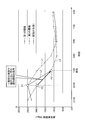
- FIG. 27 is a diagram showing the time dependence of the communication traffic.
- the policy control device can only transmit the control policy to the router at regular intervals, and there is no immediacy of the traffic control. (See (1) in FIG. 27).
- the number of times of notification of the signal amount is greatly reduced in a time zone in which the user communication amount is reduced, that is, in a time period in which the communication amount is greatly reduced. Like the described scheme, it lacks immediacy.
- the traffic volume method since the traffic volume of the user terminal varies depending on the time zone, the number of times the router reports the traffic volume to the policy control device during the time zone in which the traffic of the user terminal is concentrated. This increased the number of signals (see (2) in FIG. 27).
- the present invention has been made in view of the above, and it is an object of the present invention to obtain a notification signal from a relay device that notifies a communication amount of a user terminal with an appropriate number of signals regardless of a change in the communication amount of the user terminal. With the goal.
- a control device configured such that, when the traffic of a user terminal to be accommodated exceeds a traffic threshold, An acquisition unit that acquires the communication amount, the acquisition unit calculates the communication speed using the communication amount of the past certain period including at least the communication amount acquired this time, and a calculation unit that calculates the communication amount threshold based on the calculated communication speed. And a notifying unit that notifies the relay device of the traffic threshold calculated by the calculating unit.
- the present invention it is possible to acquire a notification signal from the relay device for notifying the traffic of the user terminal with an appropriate number of signals regardless of the increase or decrease of the traffic of the user terminal.
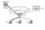
- FIG. 1 is a diagram illustrating a schematic configuration of the communication system according to the first embodiment.
- FIG. 2 is a schematic diagram showing a schematic configuration of the relay device shown in FIG.
- FIG. 3 is a diagram illustrating an example of a data configuration of a communication amount held in a memory of the relay device illustrated in FIG. 2.
- FIG. 4 is a diagram illustrating a schematic configuration of the policy control device according to the embodiment.
- FIG. 5 is a diagram illustrating a data configuration of the traffic management table.
- FIG. 6 is a diagram illustrating a data configuration of the communication speed table.
- FIG. 7 is a diagram illustrating a state in which the traffic volume of a certain user terminal changes with the passage of time.
- FIG. 1 is a diagram illustrating a schematic configuration of the communication system according to the first embodiment.
- FIG. 2 is a schematic diagram showing a schematic configuration of the relay device shown in FIG.
- FIG. 3 is a diagram illustrating an example of a data configuration of a communication amount held
- FIG. 8 is a diagram illustrating a time dependency of a traffic threshold set by the policy control device illustrated in FIG. 1.
- FIG. 9 is a diagram illustrating the time dependence of the number of notification signals from the relay device when each traffic threshold is adopted.
- FIG. 10 is a diagram illustrating the time dependence of the number of notification signals from the relay device when each traffic threshold is adopted.
- FIG. 11 is a sequence diagram showing the operation of the communication system.
- FIG. 12 is a sequence diagram showing the operation of the communication system.
- FIG. 13 is a sequence diagram showing the operation of the communication system.
- FIG. 14 is a flowchart illustrating a processing procedure of the communication method according to the first embodiment.
- FIG. 15 is a diagram showing a processing procedure of the registration and time registration processing shown in FIG. FIG.
- FIG. 16 is a diagram illustrating a processing procedure of the next traffic threshold calculation processing illustrated in FIG.
- FIG. 17 is a flowchart illustrating a processing procedure of the relay device.
- FIG. 18 is a diagram illustrating a schematic configuration of the policy control device according to the second embodiment.
- FIG. 19 is a diagram illustrating a state in which the traffic volume of a certain user terminal changes with the passage of time.
- FIG. 20 is a diagram exemplifying a state in which the traffic volume of a certain user terminal changes over time.
- FIG. 21 is a diagram showing a time change of the weight.
- FIG. 22 is a diagram illustrating a state in which the traffic volume of a certain user terminal changes with the passage of time.
- FIG. 23 is a diagram illustrating a temporal change in weight.
- FIG. 24 is a flowchart illustrating a processing procedure of the communication method according to the second embodiment.
- FIG. 25 is a diagram depicting a processing procedure of a next traffic threshold calculation processing illustrated in FIG. 24;
- FIG. 26 is a diagram illustrating an example of a computer in which a policy control device is realized by executing a program.
- FIG. 27 is a diagram illustrating the time dependency of the communication traffic.
- FIG. 1 is a diagram illustrating a schematic configuration of the communication system according to the first embodiment.
- the communication system according to the first embodiment includes a relay device 10 and a policy control device 20 (control device), and connects a telecommunication line 30 such as a LAN (Local Area Network) or the Internet.
- a telecommunication line 30 such as a LAN (Local Area Network) or the Internet.
- the relay device 10 accommodates a user terminal 40 used by a user who uses the Web service.
- the relay device 10 has a PCEF (Policy ⁇ and ⁇ Charging ⁇ Enforcement ⁇ Function).
- the relay device 10 measures the traffic of each user terminal 40 accessing the Web server via the Internet, and when the traffic exceeds the traffic threshold notified from the policy controller 20, the relay device 10 sends the traffic to the policy controller 20. Notice.
- the relay device 10 controls the traffic of each user terminal 40 according to the control policy notified from the policy control device 20 according to the traffic.
- the policy control device 20 has a PCRF (Policy and Charging Rules Function) and manages a control policy for controlling traffic for each user terminal 40.
- the policy control device 20 determines a control policy according to the traffic of each user terminal 40 notified from the relay device 10 and notifies the relay device 10 of the control policy. Further, the policy control device 20 calculates a traffic threshold and notifies the relay device 10 of the calculated traffic threshold, and acquires the traffic reported from the relay device 10 when the traffic of the user terminal 40 exceeds the traffic threshold.
- PCRF Policy and Charging Rules Function
- FIG. 2 is a schematic diagram showing a schematic configuration of the relay device 10 shown in FIG.
- the relay device 10 includes a communication control unit 11, a traffic management unit 12, a traffic notification unit 13, a routing unit 14, and a traffic control unit 15.
- the communication control unit 11 is realized by an NIC (Network Interface Card) or the like, and controls communication with an external device such as the policy control device 20 or the user terminal 40 via an electric communication line such as a LAN or the Internet.
- NIC Network Interface Card
- the traffic management unit 12, the communication notification unit 13, the routing unit 14, and the traffic control unit 15 use electronic circuits such as a CPU (Central Processing Unit) and integrated circuits such as an ASIC (Application Specific Integrated Circuit). Is achieved.
- a CPU Central Processing Unit
- ASIC Application Specific Integrated Circuit
- the traffic management unit 12 measures the traffic of the user terminal 40 and stores the measured traffic in a memory (not shown). That is, the traffic management unit 12 measures the traffic by accumulating the packet size of the packet received from the user terminal 40 via the communication control unit 11 in the memory.
- FIG. 3 is a diagram exemplifying a data configuration of the communication amount held in the memory of the relay device 10 shown in FIG.
- the uplink means traffic from the user terminal 40 to a direction inside the network.
- Downlink means traffic from the inside of the network to the user terminal 40.
- the total amount means the sum of the up and down.
- FIG. 3 illustrates that, for a user terminal 40 of “Xxxx”, for example, the uplink traffic is 300M, the downlink traffic is 1500M, and the total traffic, that is, the total traffic of uplink and downlink is 1800M.
- the communication amount management unit 12 notifies the communication amount notification unit 13 of the communication amount when the communication amount threshold value received by the communication amount notification unit 13 is exceeded.
- the communication amount threshold will be described later.
- the communication amount management unit 12 also resets the communication amount accumulated in the memory to zero.
- the communication amount notification unit 13 receives a communication amount threshold and a control policy, which will be described later, from the policy control device 20 via the communication control unit 11. When notified of the communication amount from the communication amount management unit 12, the communication amount notification unit 13 notifies the policy control device 20 via the communication control unit 11.
- the routing unit 14 When the routing unit 14 receives a packet from the user terminal 40 via the communication control unit 11, the routing unit 14 determines a next hop with reference to the destination IP address, and transmits the packet to the determined next hop.
- the traffic control unit 15 controls the traffic of packets transmitted to and received from the user terminal 40 via the communication control unit 11 according to the control policy received by the traffic management unit 12.
- FIG. 4 is a diagram illustrating a schematic configuration of the policy control device 20 according to the embodiment.
- the policy control device 20 determines a control policy according to the traffic of each user terminal 40 notified from the relay device 10 and notifies the relay device 10 of the control policy.
- the policy control device 20 executes a notification process described later, calculates a traffic threshold, notifies the relay device 10, and notifies the relay device 10 when the traffic of the user terminal 40 exceeds the traffic threshold.
- the policy control device 20 includes a communication control unit 21, a storage unit 22, and a control unit 23.
- the communication control unit 21 is realized by an NIC or the like, and controls communication between the control unit 23 and an external device such as the relay device 10 via an electric communication line such as a LAN or the Internet.
- the storage unit 22 is realized by a semiconductor memory device such as a random access memory (RAM) or a flash memory, or a storage device such as a hard disk or an optical disk.
- the storage unit 22 may communicate with the control unit 23 via the communication control unit 21.
- the storage unit 22 stores a traffic management table 221, a communication speed table 222, a traffic threshold 223 for time notification, and a control policy 224.
- the traffic management table 221 stores the traffic at each time for each user terminal 40.
- FIG. 5 is a diagram illustrating a data configuration of the traffic management table 221.
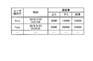
- the traffic management table 221 includes a user identifier for identifying the user terminal 40, time, and traffic.
- data see FIG. 3 notified from the relay device 10 is registered.
- the time means the time at which the communication amount is notified from the relay device 10. This time is equal to the time when the acquisition unit 231 described later acquires the traffic from the relay device 10.
- FIG. 5 shows that, for example, at 19:51:00 on May 29, 2018, the user terminal 40 of “Xxxx” has an uplink traffic of 300M, a downlink traffic of 1500M, and a total traffic of 1800M. It is shown that the communication amount data is notified from the relay device 10.
- the communication speed table 222 stores the communication speed of each cycle for each user terminal.
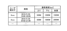
- FIG. 6 is a diagram illustrating a data configuration of the communication speed table 222. As illustrated in FIG. 6, the communication speed table 222 includes a user identifier for identifying the user terminal 40, a cycle, and a communication speed.
- the cycle means a cycle of notifying the communication amount by the relay device 10.
- the communication speed includes the total amount in addition to the uplink and downlink.
- FIG. 6 shows, for example, in the period from 19:00 to 20:00 on May 29, 2018, the user terminal 40 of “Xxxx” has an uplink communication speed of 500 Mbps [bps] and a downlink communication speed of 1000 Mbps [bps]. , The total amount is 1500 Mbps.
- the communication amount threshold 223 of the time notification is a communication amount assumed to be notified for each time in the time method. That is, the communication amount threshold value 223 of the time notification is a second threshold value X that is a communication amount when notifying the notification communication amount at a certain time, and is set so that a predetermined number of notification signals can be received at each time. It is preset in each case. For example, when the relay device 10 under the policy control device 20 accommodates 2700 user terminals 40, the communication amount threshold of the time notification is based on the traffic of the user terminals 40, and 2700 notifications per hour are set. A communication amount at which a signal can be received is set as a second threshold value in each cycle.
- the control policy 224 indicates the contents of traffic control such as a communication band, a priority class, a communication amount, routing, or blocking.
- the control policy 224 according to the traffic of the user terminal 40 is determined, and is notified to the relay device 10.
- the relay device 10 controls traffic for each user terminal 40 according to the control policy 224.
- the control unit 23 is realized using a CPU or the like, and executes a processing program stored in a memory, thereby obtaining an acquisition unit 231, a calculation unit 232, a notification unit 233, a timer management unit 234 as illustrated in FIG. And functions as the policy determination unit 235.
- the acquisition unit 231 acquires the traffic from the relay device 10 that notifies the traffic when the traffic of the user terminal 40 accommodated in the relay device 10 exceeds the traffic threshold. Specifically, the acquiring unit 231 acquires the data of the communication amount (see FIG. 3) notified from the relay device 10 via the communication control unit 21 and stores the data in the communication amount management table 221.
- the calculation unit 232 calculates the traffic threshold based on the traffic over a certain period in the past including the traffic currently acquired by the acquisition unit 231. Specifically, the calculation unit 232 uses the communication amount acquired this time and the notification interval from the time when the previous communication amount was acquired to the time when the current communication amount is acquired to change the communication amount per unit time. Is calculated. In other words, the calculation unit 232 calculates the communication speed of the latest one cycle. Then, the calculation unit 232 obtains a first threshold value Y which is a multiplication value of the communication speed and a target value of a notification cycle in which the communication amount is notified from the relay device 10.
- the ⁇ calculation unit 232 sets the smaller one of the obtained first threshold value Y and the second threshold value X that is the communication amount when notifying the notification communication amount at every fixed time as the communication amount threshold. In other words, the calculation unit 232 sets a smaller threshold value among the multiplication value of the communication speed and the target value of the notification period and the communication amount threshold value 223 of the time notification as the communication amount threshold value.
- the notifying unit 233 notifies the relay device 10 of the traffic threshold calculated by the calculating unit 232. As described above, if the measured traffic of the user terminal 40 exceeds the notified traffic threshold for the user terminal 40, the relay device 10 reduces the traffic of the user terminal 40 to the policy control device. Notify 20. Therefore, the policy control device 20 can receive a signal notifying the traffic at a frequency not exceeding its processing performance.
- the timer management unit 234 sets the traffic threshold to be notified to the relay device 10 to 0 when the relay device 10 does not report the traffic even after the target notification period has elapsed.
- the target notification cycle is a target value of the notification cycle from the current notification to the next notification.
- the timer management unit 234 sets a timer of the target notification period T + ⁇ in order to monitor the notification of the traffic from the relay device 10.
- ⁇ represents an addition time defined by the service requirement.
- the timer management unit 234 sets the traffic threshold to 0 and notifies the notification unit 233. For example, it is considered that the speed of the change in the communication amount of the user terminal 40 decreases, and the communication amount does not exceed the communication amount threshold even when the timer expires. In this case, the relay device 10 immediately notifies the policy control device 20 of the communication amount by updating the communication amount threshold to 0. In this way, the policy control device 20 can acquire the traffic of the user terminal 40 by the push notification.
- the policy control device 20 calculates the traffic threshold again by using the traffic obtained by the push notification, thereby flexibly responding to the change speed of the traffic and applying the traffic threshold.
- a control policy 224 can be determined.
- the policy determination unit 235 refers to the control policy 224, determines a control policy to be applied to the user terminal 40 according to the traffic of each user terminal 40 notified from the relay device 10, and determines the communication control unit 21.
- the relay device 10 is notified through the relay device 10.
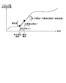
- FIG. 7 is a diagram illustrating a state in which the traffic volume of a certain user terminal 40 changes with the passage of time.
- the traffic volume means an accumulated traffic volume obtained by accumulating the traffic volume of the user terminal 40 after the measurement is started.
- the calculation of the first threshold Y will be described.
- the time from the previous notification time t 0 of the communication amount to the current notification time t, that is, the notification interval is ⁇ t
- the change in the communication amount per unit time is calculated.
- the represented communication speed s is calculated by the communication amount / ⁇ t notified at time t.
- the calculation unit 232 sets the target value of the notification cycle from the current notification to the next notification at the time t as the target notification cycle T set according to the processing performance of the policy control device 20, and reports the communication amount to be notified.
- the first threshold value Y is calculated so as to be equal to the predicted value of. That is, the first threshold value Y represents the predicted value of the communication amount at the time when the target notification period T has elapsed from the time t, and can be expressed by Expression (1).
- the target notification period T is set according to the processing performance of the policy control device 20 as described above.
- the target notification cycle T is calculated by the number of Gx sessions / processing performance of all the user terminals 40.
- the Gx session means a session for transmitting the control policy 224 established between the policy control device 20 and the relay device 10.
- the calculation unit 232 refers to the second threshold value X from the communication amount threshold value 223 of the time notification in the storage unit 22.
- a threshold having a smaller value is set as a traffic threshold.
- FIG. 8 is a diagram showing the time dependence of the traffic threshold set by the policy control device 20 shown in FIG.
- a curve L1 shown in FIG. 8 corresponds to the first threshold Y
- a curve L2 corresponds to the second threshold X
- a curve L3 corresponds to the traffic threshold set by the method of the first embodiment. I do.
- the policy control device 20 determines the first threshold Y (see the point P1 in FIG. 2) calculated in the immediately preceding cycle (23:00 to 1:00) and the second threshold X (see FIG.
- the second threshold value X having the smaller value is adopted as the traffic threshold value for the relay device 10 in the next cycle (see (1) in FIG. 8).
- the policy control device 20 adopts the second threshold value X (see the point P2 ′ in FIG. 2) in this cycle.
- FIGS. 9 and 10 are diagrams illustrating the time dependence of the number of notification signals from the relay device 10 when each traffic threshold is adopted.
- a curve M1 shows a case where the first threshold Y is applied as a traffic threshold
- a curve M2 shows a case where the second threshold X is applied as a traffic threshold
- a curve M3 shows the case of implementation.
- a case where a traffic threshold set using the method of mode 1 is applied is shown.
- the cycle T1 in FIG. 9 is a cycle in which the first threshold Y is set because X> Y (see (1) in FIG. 9).
- the period T1 is a time period during which the traffic increases
- the first threshold Y which is a multiplication value of the communication speed and the target value of the notification cycle at which the relay device 10 is notified of the traffic is applied.
- the policy control device 20 can acquire the statistical information (the number of notification signals) in which the number of signals is suppressed.
- the cycle T2 is a cycle in which the second threshold value X is set because X ⁇ Y (see (2) in FIG. 9).
- the number of times of notification of the signal amount can be kept constant although the communication amount is a small time period, so that the policy control device 20 can acquire a certain number of statistical information (the number of notification signals). it can.
- the policy control device 20 dynamically sets the traffic threshold for the relay device 10. This makes it possible to eliminate a drop in the number of notification signals from the relay device 10 even during a time zone in which the amount of user traffic is large (see (1) in FIG. 10). In addition, the policy control device 20 can appropriately acquire the statistic information while suppressing the number of notification signals from the relay device 10 even during a time period in which the user traffic increases.
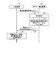
- FIG. 11 to 13 are sequence diagrams illustrating the operation of the communication system.
- an explanation will be given of an operation from the relay device 10 newly requesting the policy control device 20 to acquire the traffic threshold for the user terminal 40, acquiring the initial value of the traffic threshold, and applying the initial value. I do.
- the relay device 10 requests the user terminal 40 to acquire a traffic threshold to be applied to the user terminal 40 using a CCR-I (Credit Control Request-Initial) command (step S1).
- the policy control device 20 registers the time at which the CCR-I command was received in the traffic management table 221 (step S2).
- the calculation unit 232 sets a preset initial value as a traffic threshold. Further, the policy determination unit 235 refers to the traffic management table 221 and the control policy 224 to determine a control policy according to the traffic of the user terminal 40, that is, the initial value 0. Further, the timer management unit 234 sets a timer for monitoring the notification of the traffic (step S3).
- the policy control device 20 notifies the relay device 10 of the initial value of the traffic threshold and the control policy via the communication control unit 21 (step S4).
- the relay device 10 applies the notified traffic threshold and the control policy, and starts measuring the traffic of the user terminal 40 (step S5).
- the traffic notification unit 13 transmits the policy control device via the communication control unit 11. 20 is notified of the traffic using a CCR-U (Credit Control Request Request Update) command (step S7).
- the acquisition unit 23a registers the time at which the CCR-U command was received and the traffic of the user terminal 40 in the traffic management table 221 (step S8).
- the calculation unit 232 calculates the communication speed s and the first threshold Y, reads the second threshold X, and sets the traffic threshold. Further, the policy determination unit 235 determines a control policy according to the notified communication volume of the user terminal 40. Further, the timer management unit 234 sets a timer for monitoring the notification of the traffic (step S9).
- the policy control device 20 notifies the relay device 10 of the traffic threshold and the control policy via the communication control unit 21 by using a CCA-U (Credit Control Answer-Update) command (step S10).
- the relay device 10 applies the notified traffic threshold and the control policy (step S11).
- the communication amount of the user terminal 40 is acquired by a push notification, the communication amount threshold is updated, and the relay amount is notified to the relay device 10. The operation up to will be described.
- the timer management unit 234 sets the traffic threshold to 0. Further, the policy determination unit 235 refers to the traffic management table 221 and the control policy 224 to determine a control policy according to the traffic (step S12).
- the policy control device 20 notifies the relay device 10 via the communication control unit 21 of the traffic threshold set to 0 and the control policy using an RAR (Re Auth Request) command (step S13).
- the relay device 10 applies the notified communication amount threshold value and control policy (step S14), and notifies the communication control unit that the communication amount threshold value and the control policy have been updated using the RAA (Re @ Auth @ Answer) command.
- a response is made to the policy control device 20 via the client 11 (step S15).
- the traffic management unit 12 immediately determines that the traffic of the user terminal 40 has exceeded the traffic threshold set to 0 (step S16). Then, the communication amount notification unit 13 notifies the policy control device 20 of the communication amount using the CCR-U command via the communication control unit 11 (step S17). The policy control device 20 registers the time at which the CCR-U command was received and the traffic of the user terminal 40 in the traffic management table 221 (step S18).
- the calculation unit 232 calculates the communication speed s and the first threshold Y, reads the second threshold X, and sets the traffic threshold. Further, the policy determination unit 235 determines a control policy according to the notified communication volume of the user terminal 40. Further, the timer management unit 234 sets a timer for monitoring the notification of the traffic (step S19).
- the notification unit 23c uses the CCA-U command to notify the relay device 10 of the traffic threshold and the control policy via the communication control unit 21 (step S20).
- the relay device 10 applies the notified traffic threshold and the control policy (step S21).
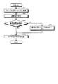
- FIG. 14 is a flowchart illustrating a processing procedure of the communication method according to the first embodiment. The flowchart of FIG. 14 is started, for example, at the timing when a packet is received from the relay device 10.
- the policy control device 20 When receiving the packet notifying the traffic of the user terminal 40 from the relay device 10 (step S31), the policy control device 20 acquires the time of the notification of the traffic (step S32) and stores at least the traffic and the time. Registration processing of the communication amount and the time to be registered in the unit 22 (step S33).
- the calculation unit 232 calculates the communication speed s using the notified communication amount (step S34), calculates the first threshold Y using the calculated communication speed s, and calculates the first threshold Y and the calculated first threshold Y.
- a traffic threshold calculation process of comparing the second threshold X referred to from the storage unit 22 and calculating a traffic threshold of the next cycle is performed (step S35).
- the policy determination unit 235 determines whether the traffic exceeds the traffic threshold with reference to the traffic management table 221 (step S36). If the traffic does not exceed the traffic threshold (step S36: No), the policy determination unit 235 determines a control policy without restriction (step S37). On the other hand, when the traffic exceeds the traffic threshold (Step S36: Yes), the policy determination unit 235 determines a control policy for performing band control according to the traffic (Step S38).
- the timer management unit 234 sets a timer for monitoring the notification of the communication amount of the user terminal 40 (step S39), and the notifying unit 233 sends the determined control policy and the calculated communication amount threshold to the relay device 10. Notify (step S40). Thus, a series of notification processing ends.
- FIG. 15 is a diagram showing a processing procedure of the registration and time registration processing shown in FIG.
- the acquisition unit 231 repeats the processing of the loop 1 to register the traffic and the time for a certain period.
- the processing of steps S41 to S47 is performed for each cycle k (1 ⁇ k ⁇ n).
- the acquisition unit 231 initializes k, and receives a communication amount notification packet from the relay device 10 (step S42).
- the acquisition unit 231 acquires the time of the communication amount notification (Step S43).
- the acquiring unit 231 registers the acquired traffic and time in the traffic management table 221 in association with the identifier of the user terminal (step S44).
- the calculation unit 232 calculates the communication speed (Step S45), and registers the time zone and the communication speed in which the communication speed was calculated in the communication speed table 222 (Step S46). Since the registration processing in this loop has been completed (step S47), 1 is added to n, and the processing of steps S42 to S46 is executed. Steps S41 to S47 are executed until k becomes n.
- FIG. 16 is a diagram illustrating a processing procedure of the next traffic threshold calculation processing illustrated in FIG.
- the calculation unit 232 refers to the traffic management table 221 (step S51), and acquires the traffic threshold 223 (second threshold X) of the time notification from the storage unit 22 (step S52). ). Then, the calculation unit 232 calculates a traffic threshold (first threshold Y) based on the communication speed of the latest one cycle (step S53).
- the calculation unit 232 compares the value of the first threshold Y with the value of the second threshold X, and determines whether or not X ⁇ Y (Step S54). When determining that X ⁇ Y is not satisfied, that is, when determining that X> Y is satisfied (step S54: No), the calculation unit 232 sets Y to the traffic threshold (step S55), and ends the process. On the other hand, when determining that X ⁇ Y is satisfied (step S54: Yes), the calculation unit 232 sets X to the traffic threshold (step S56) and ends the process.
- FIG. 17 is a flowchart illustrating a processing procedure of the relay device 10. The flowchart in FIG. 17 is started, for example, at the timing when a packet is received from the user terminal 40.
- the traffic management unit 12 receives the packet from the user terminal 40 (Step S61) and measures the traffic (Step S62). Further, the traffic management unit 12 determines whether the traffic exceeds the traffic threshold to which the traffic is applied (step S63).
- step S63: Yes When the traffic exceeds the traffic threshold (step S63: Yes), the traffic notifying unit 13 notifies the policy control device 20 of the traffic (step S64), and the routing unit 14 transmits the traffic from the user terminal 40. The packet is transferred to the next hop (step S65). On the other hand, if the traffic does not exceed the traffic threshold (step S63: No), the process proceeds to step S65.
- the policy control device 20 calculates the traffic threshold based on the traffic for a certain period in the past including the traffic acquired this time, and uses the calculated traffic threshold as the relay device. By notifying to 10, the setting of the traffic threshold value is performed. At this time, the policy control device 20 calculates the communication speed of the latest cycle, and a first threshold value that is a multiplication value of the communication speed and a target value of a notification cycle in which the communication amount is notified from the relay device 10; Among the second threshold values, which are the communication amounts when notifying the notification communication amount at regular time intervals, a threshold having a small value is set as the communication amount threshold.
- the policy control device 20 sets the first threshold Y based on the communication speed of the latest cycle for the cycle in which the traffic increases, and sends the statistical information (the number of notification signals) in which the number of signals is suppressed. get.
- the policy control device 20 can acquire the number of notification signals within a range not exceeding the processing capabilities of the policy control device 20 and the relay device 10.
- the policy control device 20 sets the second threshold value X so that the number of times of notification of the signal amount can be maintained constant in a period in which the communication amount is small, and sets a certain number of pieces of statistical information (notification Signal number) in a timely manner.
- the policy control device 20 suppresses the number of notification signals from the relay device 10 by dynamically setting the traffic threshold for the relay device 10 even during a time period when the user traffic increases. In this way, it is possible to appropriately acquire statistical information, and it is possible to eliminate a drop in the number of notification signals from the relay device 10 even in a time zone in which the amount of communication decreases significantly.
- policy control device 20 obtains a notification signal from the relay device for notifying the traffic of the user terminal with an appropriate number of signals regardless of the increase or decrease in the traffic of the user terminal. can do.
- FIG. 18 is a diagram illustrating a schematic configuration of the policy control device according to the second embodiment.
- the policy control device 220 has a control unit 230 having the same function as the control unit 23, instead of the control unit 23 of the policy control device 20 shown in FIG. .
- the control unit 230 has a calculation unit 2232.
- the calculating unit 2232 calculates a communication speed indicating a change in the communication amount at predetermined intervals using the communication amount in the past certain period, and calculates a weighted moving average or an exponential moving average for each calculated communication speed. Weighting is performed to calculate a traffic threshold. Specifically, the calculation unit 2232 obtains the communication speed for each cycle, obtains the integrated value of the weight set for each cycle and the communication speed for each cycle, and sets the sum of the integrated values of all the cycles as the communication amount threshold. calculate.
- FIG. 19 is a diagram illustrating a state in which the traffic volume of a certain user terminal 40 changes with the passage of time.
- the traffic volume means an accumulated traffic volume obtained by accumulating the traffic volume of the user terminal 40 after the measurement is started.
- the calculation unit 2232 sets a threshold (communication amount threshold) of the notification communication amount in the next cycle (target notification cycle T) based on the communication speed in the past certain period (see (1) in FIG. 19). At this time, calculation unit 2232 calculates the communication rate per period ⁇ t 1 ⁇ ⁇ t n, weighted according to the respective period ⁇ t 1 ⁇ ⁇ t n, by performing the communication speed of each cycle, the next Set the traffic threshold. As described above, the policy control device 220 determines the traffic threshold in consideration of the tendency of the communication speed in a certain period in the past in addition to the communication speed in the immediately preceding cycle. Thereby, the policy control device 220 can acquire the notification signal from the relay device that notifies the communication amount of the user terminal with an appropriate number of signals regardless of the increase or decrease of the communication amount of the user terminal.
- a threshold communication amount threshold
- FIG. 20 is a diagram illustrating a state in which the traffic volume of a certain user terminal 40 changes with the passage of time.
- FIG. 21 is a diagram showing a time change of the weight.
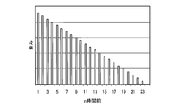
- the calculation unit 2232 uses a weighted moving average that assigns a reduced weight to each data by a fixed amount (see (1) in FIG. 20). According to the weighted moving average, the calculation unit 2232 sets the weight of the time closest to the current to n with respect to the communication amount of the past n hours, sets the previous time to n-1, and sets the previous time to n-2. And finally reduce the weight to zero.
- the calculating unit 2232 calculates the traffic threshold f (n) using the equation (2).
- C n is a communication amount increment of the period ⁇ t n .
- the calculating unit 2232 obtains the integrated value of the weight and the communication speed set for each cycle for each cycle, and calculates the sum of the integrated values as the communication amount threshold.
- FIG. 22 is a diagram illustrating a state in which the traffic volume of a certain user terminal 40 changes with the passage of time.
- FIG. 23 is a diagram illustrating a temporal change in weight.
- the calculation unit 2232 uses an exponential moving average that assigns an exponentially reduced weight to each data (see (1) in FIG. 22). According to the exponential moving average, the calculation unit 2232 sets the weight of the time closest to the present time to (1- ⁇ ) n with respect to the traffic volume of the past n hours, and sets the preceding time to (1- ⁇ ) (n ⁇ 1 ). ), And the weight of the time before that is reduced as (1 ⁇ ) (n ⁇ 2) . Note that the weight does not become zero.
- the calculation unit 2232 calculates the traffic threshold f (n) using the equation (3).
- C n is a communication amount increment of the period ⁇ t n .
- FIG. 24 is a flowchart illustrating a processing procedure of the communication method according to the second embodiment. Steps S71 to S74 shown in FIG. 24 are the same processes as steps S31 to S34 shown in FIG.
- the calculation unit 232 performs the next traffic threshold calculation process of weighting the communication speed by the weighted moving average or the exponential moving average, and calculating the traffic threshold f (n) of the next cycle (step S75).
- Steps S76 to S80 are the same processing as steps S36 to S40 shown in FIG.
- FIG. 25 is a diagram depicting a processing procedure of a next traffic threshold calculation processing illustrated in FIG. 24; As shown in FIG. 25, the calculation unit 2232 refers to the traffic management table 221 (Step S81). Then, the calculation unit 2232 repeats the process of the loop 1 in order to obtain the weighted integrated value of the communication speed in each cycle in the past fixed period. Here, the processing of steps S82 to S86 is performed for each cycle k (1 ⁇ k ⁇ n).
- the calculation unit 2232 obtains the cycle and the communication speed from the storage unit 22 (Step S83), and calculates the weight of the obtained cycle (Step S84).
- the calculating unit 2232 calculates the weight using the weighted moving average method or the exponential moving average.
- the calculation unit 2232 calculates the sum of the integrated value of the acquired cycle weight and the acquired cycle communication speed (step S85). By this processing, the registration processing in this loop has been completed (step S86), so 1 is added to n, and the processing of steps S83 to S86 is executed. Steps S82 to S86 are executed until k becomes n. Then, the calculation unit 2232 derives the sum as the traffic threshold f (n) in the next cycle (step S87), and ends the process.
- the policy control device 220 calculates the communication speed using the communication amount in the past fixed period, and weights the calculated communication speed by the weighted moving average or the exponential moving average. Then, a traffic threshold is calculated. Specifically, the policy control device 220 obtains the communication speed for each cycle, obtains the integrated value of the weight set for each cycle and the communication speed for each cycle, and communicates the sum of the obtained integrated values for all the cycles. It is calculated as an amount threshold.
- the policy control device 220 dynamically determines the traffic threshold for the relay device 10 in consideration of the tendency of the communication speed in a certain past period. Thereby, the policy control device 220 can acquire the notification signal from the relay device that notifies the communication amount of the user terminal with an appropriate number of signals regardless of the increase or decrease of the communication amount of the user terminal.
- Each component of the policy control devices 20 and 220 illustrated in FIGS. 4 and 18 is a functional concept, and does not necessarily need to be physically configured as illustrated. That is, the specific form of the distribution and integration of the functions of the policy control devices 20 and 220 is not limited to the illustrated one, and all or a part of the functions may be divided into functional units in arbitrary units according to various loads and usage conditions. Alternatively, they can be physically dispersed or integrated.
- each processing performed in the policy control devices 20 and 220 may be realized by a CPU and a program analyzed and executed by the CPU. Further, each processing performed in the policy control devices 20 and 220 may be realized as hardware by wired logic.
- all or a part of the processes described as being performed automatically may be manually performed.
- all or part of the processing described as being performed manually can be automatically performed by a known method.
- the above-described and illustrated processing procedures, control procedures, specific names, and information including various data and parameters can be appropriately changed unless otherwise specified.
- FIG. 26 is a diagram illustrating an example of a computer on which the policy controllers 20 and 220 are implemented by executing a program.
- the computer 1000 has, for example, a memory 1010 and a CPU 1020.
- the computer 1000 has a hard disk drive interface 1030, a disk drive interface 1040, a serial port interface 1050, a video adapter 1060, and a network interface 1070. These components are connected by a bus 1080.
- the memory 1010 includes a ROM (Read Only Memory) 1011 and a RAM 1012.
- the ROM 1011 stores, for example, a boot program such as a BIOS (Basic Input Output System).
- BIOS Basic Input Output System
- the hard disk drive interface 1030 is connected to the hard disk drive 1090.
- the disk drive interface 1040 is connected to the disk drive 1100.
- a removable storage medium such as a magnetic disk or an optical disk is inserted into the disk drive 1100.
- the serial port interface 1050 is connected to, for example, a mouse 1110 and a keyboard 1120.
- the video adapter 1060 is connected to the display 1130, for example.
- the hard disk drive 1090 stores, for example, an operating system (OS) 1091, an application program 1092, a program module 1093, and program data 1094. That is, a program that defines each process of the policy control devices 20 and 220 is implemented as a program module 1093 in which codes executable by the computer 1000 are described.
- the program module 1093 is stored in, for example, the hard disk drive 1090.
- a program module 1093 for executing the same processing as the functional configuration in the policy control devices 20 and 220 is stored in the hard disk drive 1090.
- the hard disk drive 1090 may be replaced by an SSD (Solid State Drive).
- the setting data used in the processing of the above-described embodiment is stored as the program data 1094 in, for example, the memory 1010 or the hard disk drive 1090. Then, the CPU 1020 reads out the program module 1093 and the program data 1094 stored in the memory 1010 and the hard disk drive 1090 to the RAM 1012 as needed, and executes them.
- the program module 1093 and the program data 1094 are not limited to being stored in the hard disk drive 1090, but may be stored in, for example, a removable storage medium and read out by the CPU 1020 via the disk drive 1100 or the like. Alternatively, the program module 1093 and the program data 1094 may be stored in another computer connected via a network (LAN, Wide Area Network (WAN), or the like). Then, the program module 1093 and the program data 1094 may be read from another computer by the CPU 1020 via the network interface 1070.
- LAN Local Area Network
- WAN Wide Area Network
- Reference Signs List 10 relay device 11 communication control unit 12 communication amount management unit 13 communication amount notification unit 14 routing unit 15 traffic control unit 20, 220 policy control device 21 communication control unit 22 storage unit 221 communication amount management table 222 communication speed table 223 Time notification Communication amount threshold 224 Control policy 23,230 Control unit 231 Acquisition unit 232,2322 Calculation unit 233 Notification unit 234 Timer management unit 235 Policy determination unit 30 Telecommunication line 40 User terminal
Landscapes
- Engineering & Computer Science (AREA)
- Computer Networks & Wireless Communication (AREA)
- Signal Processing (AREA)
- Environmental & Geological Engineering (AREA)
- Data Exchanges In Wide-Area Networks (AREA)
- Small-Scale Networks (AREA)
Abstract
ポリシー制御装置(20)は、収容するユーザ端末の通信量が通信量閾値を超えた場合に、通信量を通知する中継装置から、通信量を取得する取得部(231)と、取得部(231)が今回取得した通信量を少なくとも含む過去の一定期間の通信量を用いて通信速度を算出し、算出した通信速度を基に通信量閾値を算出する算出部(232)と、算出部(232)が算出した通信量閾値を中継装置に通知する通知部(233)と、を有する。
Description
本発明は、制御装置及び制御方法に関する。
モバイル端末の普及、オンライン動画配信やクラウドサービスの利用拡大により、通信インフラを流れるトラヒックが大幅に増加している。このトラヒック量の増加に対応するため、ネットワークにポリシー制御技術を適用して、ユーザ端末毎にトラヒックを制御している。
ポリシー制御技術では、個々のパケットの内容が参照され、ユーザ端末毎あるいはアプリケーション毎に、通信帯域、優先クラス、通信量、ルーティング、または遮断等の制御ポリシーが制御される。例えば、制御ポリシーを管理するポリシー制御装置は、ユーザ端末を収容するルータからユーザ端末の通信量を取得して、通信量が多いユーザ端末の通信帯域を制限する制御ポリシーを中継装置(例えば、ルータ)に送信する。ルータは、受信した制御ポリシーに従って、対象ユーザ端末の通信帯域を制限する。
3GPP(3rd Generation Partnership Project)において、ポリシー制御装置が通信量を取得する方式に、時刻方式と通信量方式とが規定されている(非特許文献1,2参照)。時刻方式では、一定時間が経過した際に、ルータがポリシー制御装置に通信量を通知する。
一方、通信量方式では、ポリシー制御装置が指定した通信量閾値をユーザ端末の通信量が超過した場合に、ルータがポリシー制御装置に通信量を通知する。ここで、ユーザ端末の通信量には、時間帯によりばらつきがある(非特許文献3参照)。
なお、ポリシー制御装置が単位時間当たりに処理可能な信号量には制限があるため、ルータからポリシー制御装置へ送信する信号数を抑制する必要がある。そこで、ポリシー制御装置に代わって、ルータがユーザ端末の通信量を管理して適用する制御ポリシーを判断することにより、ルータからポリシー制御装置へ送信する信号数を抑制する方式も提案されている(特許文献1参照)。しかしながら、この方式は、3GPPの標準動作には規定されていない。
また、適時に信号数を抑制して通知する方式も提案されている(特許文献2参照)。この方式によれば、通信量が増大する時間帯では、適時に統計情報を取得することができるという改善効果が見られる。
"3GPP TS23.203 ver.15.0.0",[online],[平成30年8月16日検索],インターネット<URL:http://www.3gpp.org/ftp//Specs/archive/23_series/23.203/23203-f00.zip>
"3GPP TS29.212 ver.14.6.0 Release 14",[online],[平成30年8月16日検索],インターネット<URL:http://www.etsi.org/deliver/etsi_ts/129200_129299/129212/14.06.00_60/ts_129212v140600p.pdf>
「我が国のインターネットにおけるトラヒックの集計・試算(2017年11月の集計結果の公表)」,[online],[平成30年8月16日検索],インターネット<URL:http://www.soumu.go.jp/menu_news/s-news/02kiban04_04000225.html>
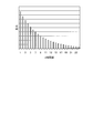
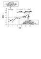
図27は、通信量の時間依存性を示す図である。3GPPで規定されている通信量の取得の方式のうち、時刻方式によれば、ポリシー制御装置はルータへの制御ポリシーの送信を一定時間毎にしか行えないため、トラヒック制御の即時性がなかった(図27の(1)参照)。そして、特許文献2記載の方式でも、ユーザ通信量が低減する時間帯、すなわち、通信量の減少が大きい時間帯においては、信号量の通知回数も大幅に低減するため、非特許文献1,2記載の方式同様、即時性が欠如する。
一方、通信量方式によれば、ユーザ端末の通信量には、時間帯によりばらつきがあるため、ユーザ端末のトラヒックが集中する時間帯には、ルータからポリシー制御装置へ通信量を通知する回数が増大し信号数が増大していた(図27の(2)参照)。
本発明は、上記に鑑みてなされたものであって、ユーザ端末の通信量を通知する中継装置からの通知信号を、ユーザ端末の通信量の増減によらず、適切な信号数で取得することを目的とする。
上述した課題を解決し、目的を達成するために、本発明に係る制御装置は、収容するユーザ端末の通信量が通信量閾値を超えた場合に、通信量を通知する中継装置から、通信量を取得する取得部と、取得部が今回取得した通信量を少なくとも含む過去の一定期間の通信量を用いて通信速度を算出し、算出した通信速度を基に通信量閾値を算出する算出部と、算出部が算出した通信量閾値を中継装置に通知する通知部と、を有することを特徴とする。
本発明によれば、ユーザ端末の通信量を通知する中継装置からの通知信号を、ユーザ端末の通信量の増減によらず、適切な信号数で取得することができる。
以下、図面を参照して、本発明の一実施形態を詳細に説明する。なお、この実施の形態により本発明が限定されるものではない。また、図面の記載において、同一部分には同一の符号を付して示している。
[実施の形態]
[システム構成]
図1は、実施の形態1に係る通信システムの概略構成を示す図である。図1に示すように、本実施の形態1に係る通信システムは、中継装置10とポリシー制御装置20(制御装置)とを有し、LAN(Local Area Network)やインターネットなどの電気通信回線30を介して相互に通信可能に接続されている。
[システム構成]
図1は、実施の形態1に係る通信システムの概略構成を示す図である。図1に示すように、本実施の形態1に係る通信システムは、中継装置10とポリシー制御装置20(制御装置)とを有し、LAN(Local Area Network)やインターネットなどの電気通信回線30を介して相互に通信可能に接続されている。
中継装置10は、Webサービスを利用するユーザが使用するユーザ端末40を収容している。この中継装置10は、PCEF(Policy and Charging Enforcement Function)を有する。中継装置10は、インターネットを介してWebサーバにアクセスする各ユーザ端末40の通信量を測定し、ポリシー制御装置20から通知された通信量閾値を超えた場合に、ポリシー制御装置20に通信量を通知する。また、中継装置10は、通信量に応じてポリシー制御装置20から通知された制御ポリシーに従って、各ユーザ端末40のトラヒックを制御する。
ポリシー制御装置20は、PCRF(Policy and Charging Rules Function)を有し、ユーザ端末40毎のトラヒックを制御するための制御ポリシーを管理する。ポリシー制御装置20は、中継装置10から通知された各ユーザ端末40の通信量に応じた制御ポリシーを決定して中継装置10に通知する。また、ポリシー制御装置20は、通信量閾値を算出して中継装置10に通知し、ユーザ端末40の通信量が通信量閾値を超えた場合に中継装置10から通知される通信量を取得する。
[中継装置の構成]
まず、中継装置10の構成について説明する。図2は、図1に示す中継装置10の概略構成を示す模式図である。図2に例示するように、中継装置10は、通信制御部11、通信量管理部12、通信量通知部13、ルーティング部14、及びトラヒック制御部15を備える。
まず、中継装置10の構成について説明する。図2は、図1に示す中継装置10の概略構成を示す模式図である。図2に例示するように、中継装置10は、通信制御部11、通信量管理部12、通信量通知部13、ルーティング部14、及びトラヒック制御部15を備える。
通信制御部11は、NIC(Network Interface Card)等で実現され、ポリシー制御装置20やユーザ端末40等の外部の装置とのLANやインターネットなどの電気通信回線を介した通信を制御する。
通信量管理部12、通信量通知部13、ルーティング部14、及び、トラヒック制御部15は、CPU(Central Processing Unit)等の電子回路や、ASIC(Application Specific Integrated Circuit)等の集積回路を用いて実現される。
通信量管理部12は、ユーザ端末40の通信量を測定して不図示のメモリに保持する。すなわち、通信量管理部12は、通信制御部11を介してユーザ端末40から受信したパケットのパケットサイズをメモリに累積することにより、通信量を測定する。
図3は、図2に示す中継装置10のメモリに保持される通信量のデータ構成を例示する図である。図3に示すように、ユーザ端末40を識別するユーザ識別子毎に、上り、下り及び総量の通信量が保持される。ここで、上りとは、ユーザ端末40からネットワーク内部の方向へのトラヒックを意味する。下りとは、ネットワーク内部からユーザ端末40へのトラヒックを意味する。総量とは、上り及び下りの合計を意味する。図3には、例えば「Xxxx」のユーザ端末40について、上りの通信量が300M、下りの通信量が1500M、総量すなわち上りと下りと合計の通信量が1800Mであることが例示されている。
通信量管理部12は、通信量通知部13が受信した通信量閾値を超えた場合に、通信量通知部13に通信量を通知する。通信量閾値については後述する。なお、通信量管理部12は、通信量を通知した場合に、あわせてメモリに累積されている通信量を0にリセットする。
通信量通知部13は、ポリシー制御装置20から通信制御部11を介して、後述する通信量閾値及び制御ポリシーを受信する。また、通信量通知部13は、通信量管理部12から通信量を通知された場合に、通信制御部11を介してポリシー制御装置20に通知する。
ルーティング部14は、通信制御部11を介してユーザ端末40からパケットを受信したら、宛先IPアドレスを参照してネクストホップを判定し、判定したネクストホップに送信する。
トラヒック制御部15は、通信量管理部12が受信した制御ポリシーに従って、通信制御部11を介してユーザ端末40との間で送受されるパケットのトラヒックを制御する。
[ポリシー制御装置の構成]
次に、ポリシー制御装置の構成について説明する。図4は、実施の形態に係るポリシー制御装置20の概略構成を示す図である。ポリシー制御装置20は、中継装置10から通知された各ユーザ端末40の通信量に応じた制御ポリシーを決定して中継装置10に通知する。また、ポリシー制御装置20は、後述する通知処理を実行し、通信量閾値を算出して中継装置10に通知し、ユーザ端末40の通信量が通信量閾値を超えた場合に中継装置10から通知される通信量を取得する。図4に例示するように、このポリシー制御装置20は、通信制御部21、記憶部22、及び制御部23を備える。
次に、ポリシー制御装置の構成について説明する。図4は、実施の形態に係るポリシー制御装置20の概略構成を示す図である。ポリシー制御装置20は、中継装置10から通知された各ユーザ端末40の通信量に応じた制御ポリシーを決定して中継装置10に通知する。また、ポリシー制御装置20は、後述する通知処理を実行し、通信量閾値を算出して中継装置10に通知し、ユーザ端末40の通信量が通信量閾値を超えた場合に中継装置10から通知される通信量を取得する。図4に例示するように、このポリシー制御装置20は、通信制御部21、記憶部22、及び制御部23を備える。
通信制御部21は、NIC等で実現され、LANやインターネットなどの電気通信回線を介した中継装置10等の外部の装置と制御部23との通信を制御する。
記憶部22は、RAM(Random Access Memory)、フラッシュメモリ(Flash Memory)等の半導体メモリ素子、または、ハードディスク、光ディスク等の記憶装置によって実現される。なお、記憶部22は、通信制御部21を介して制御部23と通信する構成でもよい。記憶部22には、通信量管理テーブル221、通信速度テーブル222、時刻通知の通信量閾値223及び制御ポリシー224が記憶されている。
通信量管理テーブル221は、ユーザ端末40毎に、各時刻の通信量を記憶する。図5は、通信量管理テーブル221のデータ構成を例示する図である。図5に例示するように、通信量管理テーブル221は、ユーザ端末40を識別するユーザ識別子、時刻及び通信量を含む。ユーザ識別子及び通信量は、中継装置10から通知されたデータ(図3参照)が登録される。時刻とは、中継装置10から通信量が通知された時刻を意味する。この時刻は、後述する取得部231が中継装置10から通信量を取得する時刻に等しい。
図5には、例えば、2018年5月29日19時51分00秒に、「Xxxx」のユーザ端末40について、上りの通信量300M、下りの通信量1500M、総量が1800Mであることを示す通信量のデータが中継装置10から通知されたことが示されている。
通信速度テーブル222は、ユーザ端末毎に、各周期の通信速度を記憶する。図6は、通信速度テーブル222のデータ構成を例示する図である。図6に例示するように、通信速度テーブル222は、ユーザ端末40を識別するユーザ識別子、周期及び通信速度を含む。周期とは、中継装置10による通信量の通知周期を意味する。通信速度は、上りと下り加え、総量も含む。
図6には、例えば、2018年5月29日19:00-20:00の周期において、「Xxxx」のユーザ端末40について、上りの通信速度500M[bps]、下りの通信速度1000M[bps]、総量が1500M[bps]であることが示されている。
時刻通知の通信量閾値223は、時刻方式において時刻毎に通知されると想定された通信量である。すなわち、時刻通知の通信量閾値223は、一定時刻毎に通知通信量を通知する場合の通信量である第2の閾値Xであり、各時刻で所定数の通知信号数が受信できるように周期毎に予め設定されている。例えば、2700個のユーザ端末40を、ポリシー制御装置20下の中継装置10が収容する場合には、時刻通知の通信量閾値は、ユーザ端末40のトラヒックを基に、1時間あたり2700個の通知信号が受信できるような通信量を第2の閾値として各周期で設定する。
制御ポリシー224は、通信帯域、優先クラス、通信量、ルーティング、または遮断等のトラヒックの制御の内容を示す。ユーザ端末40の通信量に応じた制御ポリシー224が決定され、中継装置10に通知される。中継装置10は、制御ポリシー224に従ってユーザ端末40毎にトラヒックの制御を行う。
制御部23は、CPU等を用いて実現され、メモリに記憶された処理プログラムを実行することにより、図4に例示するように、取得部231、算出部232、通知部233、タイマー管理部234及びポリシー判定部235として機能する。
取得部231は、中継装置10に収容されるユーザ端末40の通信量が通信量閾値を超えた場合に通信量を通知する中継装置10から、通信量を取得する。具体的に、取得部231は、中継装置10から通知される通信量のデータ(図3参照)を、通信制御部21を介して取得して、通信量管理テーブル221に格納する。
算出部232は、取得部231が今回取得した通信量を含む過去の一定期間の通信量を基に通信量閾値を算出する。具体的には、算出部232は、今回取得された通信量と前回通信量が取得された時刻から今回通信量が取得された時刻までの通知間隔とを用いて単位時間あたりの通信量の変化を表す通信速度を算出する。言い換えると、算出部232は、直近の1周期の通信速度を算出する。そして、算出部232は、該通信速度と中継装置10から通信量が通知される通知周期の目標値との乗算値である第1の閾値Yを求める。
算出部232は、求めた第1の閾値Yと、一定時刻毎に通知通信量を通知する場合の通信量である第2の閾値Xとのうち、値が小さい閾値を通信量閾値とする。言い換えると、算出部232は、該通信速度と通知周期の目標値との乗算値と、時刻通知の通信量閾値223とのうち、値が小さい閾値を通信量閾値とする。
通知部233は、算出部232が算出した通信量閾値を中継装置10に通知する。なお、上述したように、中継装置10は、測定しているユーザ端末40の通信量が通知された該ユーザ端末40に対する通信量閾値を超えた場合に、ユーザ端末40の通信量をポリシー制御装置20に通知する。したがって、ポリシー制御装置20は、その処理性能を超えない頻度で、通信量を通知する信号を受信することができる。
タイマー管理部234は、通信量閾値を通知した後、目標通知周期が経過しても中継装置10から通信量が通知されない場合に、該中継装置10に通知する通信量閾値を0に設定する。目標通知周期は、今回の通知から次回の通知までの通知周期の目標値である。
具体的に、タイマー管理部234は、中継装置10に通信量閾値を通知した際、中継装置10からの通信量の通知を監視するため、目標通知周期T+βのタイマーを設定する。ここで、βはサービス要件により規定される加算時間を表す。
そして、タイマー管理部234は、タイマーが満了した場合に、通信量閾値を0に設定し、通知部233に通知する。例えば、ユーザ端末40の通信量の変化の速度が低下して、タイマー満了時にも通信量が通信量閾値を超えていないと考えられる。この場合に、通信量閾値が0に更新されることにより、中継装置10は直ちにポリシー制御装置20に通信量を通知する。このようにして、ポリシー制御装置20は、ユーザ端末40の通信量をプッシュ通知により取得することができる。
なお、ポリシー制御装置20は、プッシュ通知により取得した通信量を用いて通信量閾値を再度算出することにより、トラヒック量の変化の速度に柔軟に対応して、通信量閾値を算出し、適用する制御ポリシー224を判定することができる。
ポリシー判定部235は、制御ポリシー224を参照し、中継装置10から通知された各ユーザ端末40の通信量に応じて当該ユーザ端末40に対して適用する制御ポリシーを決定し、通信制御部21を介して中継装置10に通知する。
[算出部の処理]
次に、図4に示す算出部232の通信量閾値の算出処理について説明する。図7は、あるユーザ端末40のトラヒック量が時刻の経過とともに推移する様子を例示する図である。トラヒック量とは、ユーザ端末40について測定が開始されてからの通信量を累積した累積通信量を意味する。
次に、図4に示す算出部232の通信量閾値の算出処理について説明する。図7は、あるユーザ端末40のトラヒック量が時刻の経過とともに推移する様子を例示する図である。トラヒック量とは、ユーザ端末40について測定が開始されてからの通信量を累積した累積通信量を意味する。
まず、第1の閾値Yの算出について説明する。中継装置10から時刻tに通信量が通知された場合に、前回の通信量の通知時刻t0から今回の通知時刻tまでの時間すなわち通知間隔をΔtとして、単位時間あたりの通信量の変化を表す通信速度sは、時刻tに通知された通信量/Δtにより算出される。
算出された通信速度sを用いれば、次回の通知での通信量すなわちトラヒック量の増分は、通信速度s×通知間隔Δtと予測される。そこで、算出部232は、時刻tにおける今回の通知から次回の通知までの通知周期の目標値を、ポリシー制御装置20の処理性能に応じて設定される目標通知周期Tとして、通知される通信量の予測値と等しくなるように、第1の閾値Yを算出する。すなわち、第1の閾値Yは、時刻tから目標通知周期Tが経過した時点での通信量の予測値を表し、(1)式で表すことができる。

なお、目標通知周期Tは、上述したように、ポリシー制御装置20の処理性能に応じて設定される。例えば、目標通知周期Tは、全ユーザ端末40のGxセッションの数/処理性能により算出される。ここで、Gxセッションとは、ポリシー制御装置20と中継装置10との間で確立している制御ポリシー224を送信するためのセッションを意味する。
続いて、算出部232は、記憶部22の時刻通知の通信量閾値223から第2の閾値Xを参照する。第1の閾値Yと、第2の閾値Xとのうち、値が小さい閾値を通信量閾値として設定する。
図8は、図1に示すポリシー制御装置20によって設定される通信量閾値の時間依存を示す図である。図8に示す曲線L1は、第1の閾値Yに対応し、曲線L2は、第2の閾値Xに対応し、曲線L3は、本実施の形態1の手法によって設定された通信量閾値に対応する。
ポリシー制御装置20は、直前の周期(23:00~1:00)において算出された第1の閾値Y(図2の点P1参照)と、予め設定されている第2の閾値X(図2の点P2参照)との値を比較し、値が小さい第2の閾値Xを次の周期においても、中継装置10に対する通信量閾値として採用する(図8の(1)参照)。図8の例では、ポリシー制御装置20は、現在の周期(1:00~3:00)においては、この周期における第2の閾値X(図2の点P2´参照)を採用する。
図9及び図10は、各通信量閾値を採用した際の中継装置10からの通知信号数の時間依存性を示す図である。図9において、曲線M1は、第1の閾値Yを通信量閾値として適用した場合を示し、曲線M2は、第2の閾値Xを通信量閾値として適用した場合を示し、曲線M3は、実施の形態1の方式を用いて設定した通信量閾値を適用した場合を示す。
図9の周期T1は、X>Yのため第1の閾値Yが設定された周期である(図9の(1)参照)。周期T1は、通信量が増大する時間帯であるものの、通信速度と中継装置10から通信量が通知される通知周期の目標値との乗算値である第1の閾値Yを適用しているため、ポリシー制御装置20は、信号数を抑制した統計情報(通知信号数)を取得することができる。一方、周期T2は、X≦Yのため第2の閾値Xが設定された周期である(図9の(2)参照)。周期T2では、通信量が少ない時間帯であるものの、信号量の通知回数を一定に維持することができるため、ポリシー制御装置20は、一定数の統計情報(通知信号数)を取得することができる。
このように、ポリシー制御装置20は、中継装置10に対する通信量閾値を動的に設定する。これによって、ユーザ通信量の減少が大きい時間帯であっても、中継装置10からの通知信号数の落ち込みを解消することが可能になる(図10の(1)参照)。また、ポリシー制御装置20は、ユーザ通信量が増大する時間帯であっても、中継装置10からの通知信号数を抑制しながら統計情報を適切に取得することが可能になる。
[通信システムの動作]
図11~図13は、通信システムの動作を示すシーケンス図である。まず、図11を参照し、中継装置10が、ポリシー制御装置20に新規にユーザ端末40に対する通信量閾値の取得を要求し、通信量閾値の初期値を取得して適用するまでの動作について説明する。
図11~図13は、通信システムの動作を示すシーケンス図である。まず、図11を参照し、中継装置10が、ポリシー制御装置20に新規にユーザ端末40に対する通信量閾値の取得を要求し、通信量閾値の初期値を取得して適用するまでの動作について説明する。
まず、中継装置10は、CCR-I(Credit Control Request-Initial)コマンドを用いて、ユーザ端末40に対して適用する通信量閾値の取得を要求する(ステップS1)。ポリシー制御装置20は、CCR-Iコマンドを受信した時刻を通信量管理テーブル221に登録する(ステップS2)。
ポリシー制御装置20では、算出部232が、予め設定されている初期値を通信量閾値として設定する。また、ポリシー判定部235が、通信量管理テーブル221及び制御ポリシー224を参照し、ユーザ端末40の通信量すなわち初期値0に応じた制御ポリシーを決定する。また、タイマー管理部234が、通信量の通知を監視するタイマーを設定する(ステップS3)。
ポリシー制御装置20は、通信制御部21を介して中継装置10に通信量閾値の初期値と制御ポリシーとを通知する(ステップS4)。中継装置10は、通知された通信量閾値と制御ポリシーとを適用し、ユーザ端末40の通信量の測定を開始する(ステップS5)。
次に、図12を参照して、中継装置10がポリシー制御装置20にユーザ端末40の通信量を通知して、ポリシー制御装置20から通知された通信量閾値を適用するまでの動作について説明する。
中継装置10では、通信量管理部12がユーザ端末40の通信量が通信量閾値を超過したことを検出した場合(ステップS6)、通信量通知部13が通信制御部11を介してポリシー制御装置20に、CCR-U(Credit Control Request-Update)コマンドを用いて通信量を通知する(ステップS7)。ポリシー制御装置20では、取得部23aが、CCR-Uコマンドを受信した時刻とユーザ端末40の通信量とを通信量管理テーブル221に登録する(ステップS8)。
ポリシー制御装置20では、算出部232が、通信速度s及び第1の閾値Yの算出を行い、第2の閾値Xを読み出して、通信量閾値を設定する。また、ポリシー判定部235が、通知されたユーザ端末40の通信量に応じた制御ポリシーを決定する。また、タイマー管理部234が、通信量の通知を監視するタイマーを設定する(ステップS9)。
ポリシー制御装置20は、CCA-U(Credit Control Answer-Update)コマンドを用いて、通信制御部21を介して中継装置10に通信量閾値と制御ポリシーとを通知する(ステップS10)。中継装置10は、通知された通信量閾値と制御ポリシーとを適用する(ステップS11)。
次に、図13を参照して、ポリシー制御装置20が設定したタイマーが満了した場合に、ユーザ端末40の通信量をプッシュ通知で取得し、通信量閾値を更新して中継装置10に通知するまでの動作について説明する。
ポリシー制御装置20では、タイマー管理部234が、タイマーの満了を検出すると、通信量閾値を0に設定する。また、ポリシー判定部235が、通信量管理テーブル221及び制御ポリシー224を参照し、通信量に応じた制御ポリシーを決定する(ステップS12)。
ポリシー制御装置20は、通信制御部21を介して中継装置10に、RAR(Re Auth Request)コマンドを用いて、0に設定された通信量閾値と制御ポリシーとを通知する(ステップS13)。中継装置10は、通知された通信量閾値と制御ポリシーとを適用し(ステップS14)、RAA(Re Auth Answer)コマンドを用いて、通信量閾値と制御ポリシーとを更新したことを、通信制御部11を介してポリシー制御装置20に応答する(ステップS15)。
中継装置10では、通信量管理部12が直ちに、0に設定された通信量閾値をユーザ端末40の通信量が超過したと判定する(ステップS16)。そして、通信量通知部13が、通信制御部11を介してポリシー制御装置20に、CCR-Uコマンドを用いて通信量を通知する(ステップS17)。ポリシー制御装置20は、CCR-Uコマンドを受信した時刻とユーザ端末40の通信量とを通信量管理テーブル221に登録する(ステップS18)。
ポリシー制御装置20では、算出部232が、通信速度s及び第1の閾値Yの算出を行い、第2の閾値Xを読み出して、通信量閾値を設定する。また、ポリシー判定部235が、通知されたユーザ端末40の通信量に応じた制御ポリシーを決定する。また、タイマー管理部234が、通信量の通知を監視するタイマーを設定する(ステップS19)。
ポリシー制御装置20では、通知部23cが、CCA-Uコマンドを用いて、通信制御部21を介して中継装置10に通信量閾値と制御ポリシーとを通知する(ステップS20)。中継装置10は、通知された通信量閾値と制御ポリシーとを適用する(ステップS21)。
[通知処理]
次に、図14を参照して、ポリシー制御装置20による通信量閾値の通知処理について説明する。図14は、実施の形態1に係る通信方法の処理手順を示すフローチャートである。図14のフローチャートは、例えば、中継装置10からパケットを受信したタイミングで開始される。
次に、図14を参照して、ポリシー制御装置20による通信量閾値の通知処理について説明する。図14は、実施の形態1に係る通信方法の処理手順を示すフローチャートである。図14のフローチャートは、例えば、中継装置10からパケットを受信したタイミングで開始される。
ポリシー制御装置20は、中継装置10からユーザ端末40の通信量を通知するパケットを受信すると(ステップS31)、通信量の通知の時刻を取得し(ステップS32)、少なくとも通信量と時刻とを記憶部22に登録する通信量及び時刻の登録処理(ステップS33)。
算出部232は、通知された通信量を用いて通信速度sを算出し(ステップS34)、算出された通信速度sを用いて第1の閾値Yを算出し、算出した第1の閾値Yと記憶部22から参照した第2の閾値Xとを比較して、次回周期の通信量閾値を算出する通信量閾値算出処理を行う(ステップS35)。
ポリシー判定部235は、通信量管理テーブル221を参照して通信量が通信量閾値を超過しているか否かを判定する(ステップS36)。通信量が通信量閾値を超過していない場合には(ステップS36:No)、ポリシー判定部235は、規制なしの制御ポリシーを決定する(ステップS37)。一方、通信量が通信量閾値を超過している場合には(ステップS36:Yes)、ポリシー判定部235は、通信量に応じて帯域制御を行う制御ポリシーを決定する(ステップS38)。
タイマー管理部234が、ユーザ端末40の通信量の通知を監視するためのタイマーを設定する(ステップS39)とともに、通知部233が、決定した制御ポリシーと算出した通信量閾値とを中継装置10に通知する(ステップS40)。これにより、一連の通知処理が終了する。
[通信量及び時刻の登録処理の処理手順]
次に、登録及び時刻の登録処理(図14のステップS33)の処理手順について説明する。図15は、図14に示す登録及び時刻の登録処理の処理手順を示す図である。図15に示すように、取得部231は、一定期間の通信量及び時刻を登録するため、ループ1の処理を繰り返す。ここでは、周期k(1≦k≦n)毎にステップS41~ステップS47の処理を行う。まず、取得部231は、kを初期化し、中継装置10から通信量通知のパケットを受信する(ステップS42)。
次に、登録及び時刻の登録処理(図14のステップS33)の処理手順について説明する。図15は、図14に示す登録及び時刻の登録処理の処理手順を示す図である。図15に示すように、取得部231は、一定期間の通信量及び時刻を登録するため、ループ1の処理を繰り返す。ここでは、周期k(1≦k≦n)毎にステップS41~ステップS47の処理を行う。まず、取得部231は、kを初期化し、中継装置10から通信量通知のパケットを受信する(ステップS42)。
続いて、取得部231は、通信量通知の時刻を取得する(ステップS43)。取得部231は、取得した通信量及び時刻を、ユーザ端末の識別子に対応付けて通信量管理テーブル221に登録する(ステップS44)。続いて、算出部232は、通信速度を算出し(ステップS45)、通信速度を算出した時間帯と通信速度とを通信速度テーブル222に登録する(ステップS46)。このループにおける登録処理は終了したため(ステップS47)、nに1を加算して、ステップS42~ステップS46の処理を実行する。ステップS41~ステップS47の処理は、kがnになるまで実行される。
[次回通信量閾値算出処理の処理手順]
次に、次回通信量閾値算出処理(図14のステップS35)の処理手順について説明する。図16は、図15に示す次回通信量閾値算出処理の処理手順を示す図である。図16に示すように、算出部232は、通信量管理テーブル221を参照するとともに(ステップS51)、時刻通知の通信量閾値223(第2の閾値X)を記憶部22から取得する(ステップS52)。そして、算出部232は、直近の1周期の通信速度を基づく通信量閾値(第1の閾値Y)を算出する(ステップS53)。
次に、次回通信量閾値算出処理(図14のステップS35)の処理手順について説明する。図16は、図15に示す次回通信量閾値算出処理の処理手順を示す図である。図16に示すように、算出部232は、通信量管理テーブル221を参照するとともに(ステップS51)、時刻通知の通信量閾値223(第2の閾値X)を記憶部22から取得する(ステップS52)。そして、算出部232は、直近の1周期の通信速度を基づく通信量閾値(第1の閾値Y)を算出する(ステップS53)。
算出部232は、第1の閾値Yと第2の閾値Xとの値を比較し、X≦Yであるか否かを判定する(ステップS54)。算出部232は、X≦Yでないと判定した場合、すなわち、X>Yであると判定した場合(ステップS54:No)、通信量閾値にYを設定する(ステップS55)、処理を終了する。一方、算出部232は、X≦Yであると判定した場合(ステップS54:Yes)、通信量閾値にXを設定して(ステップS56)、処理を終了する。
[中継装置における処理手順]
次に、図17を参照して、ポリシー制御装置20から通信量閾値を通知された後の中継装置10の処理について説明する。図17は、中継装置10の処理手順を示すフローチャートである。図17のフローチャートは、例えば、ユーザ端末40からパケットを受信したタイミングで開始される。
次に、図17を参照して、ポリシー制御装置20から通信量閾値を通知された後の中継装置10の処理について説明する。図17は、中継装置10の処理手順を示すフローチャートである。図17のフローチャートは、例えば、ユーザ端末40からパケットを受信したタイミングで開始される。
中継装置10では、通信量管理部12が、ユーザ端末40からのパケットを受信して(ステップS61)、通信量を測定する(ステップS62)。また、通信量管理部12が、通信量が適用されている通信量閾値を超過しているか否かを判定する(ステップS63)。
通信量が通信量閾値を超過している場合(ステップS63:Yes)、通信量通知部13がポリシー制御装置20に通信量を通知する(ステップS64)とともに、ルーティング部14がユーザ端末40からのパケットをネクストホップに転送する(ステップS65)。一方、通信量が通信量閾値を超過していない場合には(ステップS63:No)、ステップS65に処理を進める。
[実施の形態1の効果]
このように、本実施の形態1に係るポリシー制御装置20は、今回取得した通信量を含む過去の一定期間の通信量を基に、通信量閾値を算出し、算出した通信量閾値を中継装置10に通知することで、通信量閾値の設定を行う。この際、ポリシー制御装置20は、直近の周期の通信速度を算出し、該通信速度と中継装置10から通信量が通知される通知周期の目標値との乗算値である第1の閾値と、一定時刻毎に通知通信量を通知する場合の通信量である第2の閾値とのうち、値が小さい閾値を通信量閾値とする。
このように、本実施の形態1に係るポリシー制御装置20は、今回取得した通信量を含む過去の一定期間の通信量を基に、通信量閾値を算出し、算出した通信量閾値を中継装置10に通知することで、通信量閾値の設定を行う。この際、ポリシー制御装置20は、直近の周期の通信速度を算出し、該通信速度と中継装置10から通信量が通知される通知周期の目標値との乗算値である第1の閾値と、一定時刻毎に通知通信量を通知する場合の通信量である第2の閾値とのうち、値が小さい閾値を通信量閾値とする。
すなわち、ポリシー制御装置20は、通信量が増大する周期に対しては、直近の周期の通信速度に基づく第1の閾値Yを設定して、信号数を抑制した統計情報(通知信号数)を取得する。ポリシー制御装置20は、ポリシー制御装置20及び中継装置10の処理能力を超えない範囲の通知信号数を取得できる。一方、ポリシー制御装置20は、通信量が少ない周期に対しては、信号量の通知回数を一定に維持することができるように第2の閾値Xを設定して、一定数の統計情報(通知信号数)を適時取得する。
上記のように、ポリシー制御装置20は、中継装置10に対する通信量閾値を動的に設定することによって、ユーザ通信量が増大する時間帯であっても、中継装置10からの通知信号数を抑制しながら統計情報を適切に取得でき、通信量の減少が大きい時間帯であっても中継装置10からの通知信号数の落ち込みを解消することが可能になる。
したがって、本実施の形態1によれば、ポリシー制御装置20は、ユーザ端末の通信量を通知する中継装置からの通知信号を、ユーザ端末の通信量の増減によらず、適切な信号数で取得することができる。
[実施の形態2]
次に、実施の形態2について説明する。図18は、実施の形態2に係るポリシー制御装置の概略構成を示す図である。
次に、実施の形態2について説明する。図18は、実施の形態2に係るポリシー制御装置の概略構成を示す図である。
図18に示すように、本実施の形態2に係るポリシー制御装置220は、図2に示すポリシー制御装置20の制御部23に代えて、制御部23と同様の機能を有する制御部230を有する。なお、実施の形態2では、記憶部22に、時刻通知の通信量閾値223を登録する必要はない。制御部230は、算出部2232を有する。
算出部2232は、過去の一定期間の通信量を用いて、通信量の変化を表す通信速度を所定の周期毎に算出し、算出した各通信速度に対して、加重移動平均または指数移動平均による重み付けを行い、通信量閾値を算出する。具体的には、算出部2232は、周期毎に通信速度を求め、周期毎に設定された重みと通信速度との積算値を周期毎に求め、全周期の積算値の和を通信量閾値として算出する。
[算出部の処理]
まず、算出部2232による通信量閾値の算出処理について説明する。図19は、あるユーザ端末40のトラヒック量が時刻の経過とともに推移する様子を例示する図である。トラヒック量とは、ユーザ端末40について測定が開始されてからの通信量を累積した累積通信量を意味する。
まず、算出部2232による通信量閾値の算出処理について説明する。図19は、あるユーザ端末40のトラヒック量が時刻の経過とともに推移する様子を例示する図である。トラヒック量とは、ユーザ端末40について測定が開始されてからの通信量を累積した累積通信量を意味する。
算出部2232は、過去の一定期間の通信速度から、次回周期(目標通知周期T)の通知通信量の閾値(通信量閾値)を設定する(図19の(1)参照)。この際、算出部2232は、周期Δt1~Δtn毎に通信速度を算出し、それぞれの周期Δt1~Δtnに応じた重み付けを、各周期の通信速度に対して行うことで、次回の通信量閾値を設定する。このように、ポリシー制御装置220は、直前の周期の通信速度に加え、過去の一定期間の通信速度の傾向を考慮の上、通信量閾値を決定する。これによって、ポリシー制御装置220は、ユーザ端末の通信量を通知する中継装置からの通知信号を、ユーザ端末の通信量の増減によらず、適切な信号数で取得することができる。
[第1の処理例]
ここで、算出部2232による通信量閾値の算出処理の例について説明する。図20は、あるユーザ端末40のトラヒック量が時刻の経過とともに推移する様子を例示する図である。図21は、重みの時間変化を示す図である。算出部2232は、図20及び図21に示すように、個々のデータに一定量ずつ減らした重みを付ける加重移動平均を用いる(図20の(1)参照)。算出部2232は、加重移動平均に従い、過去n時間の通信量に対し、最も現在に近い時間の重みをnとし、その前の時間をn-1、その前々の時間をn-2のように重みを減らしていき、最終的に重みをゼロにする。
ここで、算出部2232による通信量閾値の算出処理の例について説明する。図20は、あるユーザ端末40のトラヒック量が時刻の経過とともに推移する様子を例示する図である。図21は、重みの時間変化を示す図である。算出部2232は、図20及び図21に示すように、個々のデータに一定量ずつ減らした重みを付ける加重移動平均を用いる(図20の(1)参照)。算出部2232は、加重移動平均に従い、過去n時間の通信量に対し、最も現在に近い時間の重みをnとし、その前の時間をn-1、その前々の時間をn-2のように重みを減らしていき、最終的に重みをゼロにする。
算出部2232は、(2)式を用いて通信量閾値f(n)を算出する。Cnは、周期Δtnの通信量増分である。

このように、算出部2232は、周期毎に設定された重みと通信速度との積算値を周期毎に求め、積算値の和を通信量閾値として算出する。
[第2の処理例]
次に、算出部2232による通信量閾値の算出処理の他の例について説明する。図22は、あるユーザ端末40のトラヒック量が時刻の経過とともに推移する様子を例示する図である。図23は、重みの時間変化を示す図である。算出部2232は、図22及び図23に示すように、個々のデータに指数関数的に減少した重みを付ける指数移動平均を用いる(図22の(1)参照)。算出部2232は、指数移動平均にしたがい、過去n時間の通信量に対し、最も現在に近い時間の重みを(1-α)nとし、その前の時間を(1-α)(n-1)とし、その前々の時間を(1-α)(n-2)のように重みを減らしていく。なお、重みは0にはならない。
次に、算出部2232による通信量閾値の算出処理の他の例について説明する。図22は、あるユーザ端末40のトラヒック量が時刻の経過とともに推移する様子を例示する図である。図23は、重みの時間変化を示す図である。算出部2232は、図22及び図23に示すように、個々のデータに指数関数的に減少した重みを付ける指数移動平均を用いる(図22の(1)参照)。算出部2232は、指数移動平均にしたがい、過去n時間の通信量に対し、最も現在に近い時間の重みを(1-α)nとし、その前の時間を(1-α)(n-1)とし、その前々の時間を(1-α)(n-2)のように重みを減らしていく。なお、重みは0にはならない。
算出部2232は、(3)式を用いて通信量閾値f(n)を算出する。Cnは、周期Δtnの通信量増分である。

[通知処理]
次に、図24を参照して、ポリシー制御装置220による通信量閾値の通知処理について説明する。図24は、実施の形態2に係る通信方法の処理手順を示すフローチャートである。図24に示すステップS71~ステップS74は、図14に示すステップS31~ステップS34と同じ処理である。
次に、図24を参照して、ポリシー制御装置220による通信量閾値の通知処理について説明する。図24は、実施の形態2に係る通信方法の処理手順を示すフローチャートである。図24に示すステップS71~ステップS74は、図14に示すステップS31~ステップS34と同じ処理である。
算出部232は、通信速度に対して加重移動平均または指数移動平均による重み付けを行い、次回周期の通信量閾値f(n)を算出する次回通信量閾値算出処理を行う(ステップS75)。ステップS76~ステップS80は、図14に示すステップS36~ステップS40と同じ処理である。
[次回通信量閾値算出処理の処理手順]
次に、次回通信量閾値算出処理(図24のステップS75)の処理手順について説明する。図25は、図24に示す次回通信量閾値算出処理の処理手順を示す図である。図25に示すように、算出部2232は、通信量管理テーブル221を参照する(ステップS81)。そして、算出部2232は、過去の一定期間における各周期の通信速度の重み付け積算値を取得するため、ループ1の処理を繰り返す。ここでは、周期k(1≦k≦n)毎にステップS82~ステップS86の処理を行う。
次に、次回通信量閾値算出処理(図24のステップS75)の処理手順について説明する。図25は、図24に示す次回通信量閾値算出処理の処理手順を示す図である。図25に示すように、算出部2232は、通信量管理テーブル221を参照する(ステップS81)。そして、算出部2232は、過去の一定期間における各周期の通信速度の重み付け積算値を取得するため、ループ1の処理を繰り返す。ここでは、周期k(1≦k≦n)毎にステップS82~ステップS86の処理を行う。
まず、算出部2232は、記憶部22から周期及び通信速度の取得を行い(ステップS83)、取得した周期の重みの算出を行う(ステップS84)。算出部2232は、加重移動平均法または指数移動平均を用いて重みを算出する。
算出部2232は、取得した周期の重みと、取得した周期の通信速度との積算値の和を算出する(ステップS85)。この処理により、このループにおける登録処理は終了したため(ステップS86)、nに1を加算して、ステップS83~ステップS86の処理を実行する。ステップS82~ステップS86の処理は、kがnになるまで実行される。そして、算出部2232は、和を次回周期の通信量閾値f(n)として導出し(ステップS87)、処理を終了する。
[実施の形態2の効果]
このように、実施の形態2では、ポリシー制御装置220は、過去の一定期間の通信量を用いて通信速度を算出し、算出した通信速度に対して、加重移動平均または指数移動平均による重み付けを行い、通信量閾値を算出する。具体的には、ポリシー制御装置220は、周期毎に通信速度を求め、周期毎に設定された重みと通信速度との積算値を周期毎に求め、求めた全周期の積算値の和を通信量閾値として算出する。
このように、実施の形態2では、ポリシー制御装置220は、過去の一定期間の通信量を用いて通信速度を算出し、算出した通信速度に対して、加重移動平均または指数移動平均による重み付けを行い、通信量閾値を算出する。具体的には、ポリシー制御装置220は、周期毎に通信速度を求め、周期毎に設定された重みと通信速度との積算値を周期毎に求め、求めた全周期の積算値の和を通信量閾値として算出する。
上記のように、ポリシー制御装置220は、中継装置10に対する通信量閾値を、過去の一定期間の通信速度の傾向を考慮の上で動的に決定する。これによって、ポリシー制御装置220は、ユーザ端末の通信量を通知する中継装置からの通知信号を、ユーザ端末の通信量の増減によらず、適切な信号数で取得することができる。
[実施の形態のシステム構成について]
図4及び図18に示したポリシー制御装置20,220の各構成要素は機能概念的なものであり、必ずしも物理的に図示のように構成されていることを要しない。すなわち、ポリシー制御装置20,220の機能の分散及び統合の具体的形態は図示のものに限られず、その全部または一部を、各種の負荷や使用状況などに応じて、任意の単位で機能的または物理的に分散または統合して構成することができる。
図4及び図18に示したポリシー制御装置20,220の各構成要素は機能概念的なものであり、必ずしも物理的に図示のように構成されていることを要しない。すなわち、ポリシー制御装置20,220の機能の分散及び統合の具体的形態は図示のものに限られず、その全部または一部を、各種の負荷や使用状況などに応じて、任意の単位で機能的または物理的に分散または統合して構成することができる。
また、ポリシー制御装置20,220において行われる各処理は、全部または任意の一部が、CPU及びCPUにより解析実行されるプログラムにて実現されてもよい。また、ポリシー制御装置20,220において行われる各処理は、ワイヤードロジックによるハードウェアとして実現されてもよい。
また、実施の形態において説明した各処理のうち、自動的におこなわれるものとして説明した処理の全部または一部を手動的に行うこともできる。もしくは、手動的におこなわれるものとして説明した処理の全部または一部を公知の方法で自動的に行うこともできる。この他、上述及び図示の処理手順、制御手順、具体的名称、各種のデータやパラメータを含む情報については、特記する場合を除いて適宜変更することができる。
[プログラム]
図26は、プログラムが実行されることにより、ポリシー制御装置20,220が実現されるコンピュータの一例を示す図である。コンピュータ1000は、例えば、メモリ1010、CPU1020を有する。また、コンピュータ1000は、ハードディスクドライブインタフェース1030、ディスクドライブインタフェース1040、シリアルポートインタフェース1050、ビデオアダプタ1060、ネットワークインタフェース1070を有する。これらの各部は、バス1080によって接続される。
図26は、プログラムが実行されることにより、ポリシー制御装置20,220が実現されるコンピュータの一例を示す図である。コンピュータ1000は、例えば、メモリ1010、CPU1020を有する。また、コンピュータ1000は、ハードディスクドライブインタフェース1030、ディスクドライブインタフェース1040、シリアルポートインタフェース1050、ビデオアダプタ1060、ネットワークインタフェース1070を有する。これらの各部は、バス1080によって接続される。
メモリ1010は、ROM(Read Only Memory)1011及びRAM1012を含む。ROM1011は、例えば、BIOS(Basic Input Output System)等のブートプログラムを記憶する。ハードディスクドライブインタフェース1030は、ハードディスクドライブ1090に接続される。ディスクドライブインタフェース1040は、ディスクドライブ1100に接続される。例えば磁気ディスクや光ディスク等の着脱可能な記憶媒体が、ディスクドライブ1100に挿入される。シリアルポートインタフェース1050は、例えばマウス1110、キーボード1120に接続される。ビデオアダプタ1060は、例えばディスプレイ1130に接続される。
ハードディスクドライブ1090は、例えば、OS(Operating System)1091、アプリケーションプログラム1092、プログラムモジュール1093、プログラムデータ1094を記憶する。すなわち、ポリシー制御装置20,220の各処理を規定するプログラムは、コンピュータ1000により実行可能なコードが記述されたプログラムモジュール1093として実装される。プログラムモジュール1093は、例えばハードディスクドライブ1090に記憶される。例えば、ポリシー制御装置20,220における機能構成と同様の処理を実行するためのプログラムモジュール1093が、ハードディスクドライブ1090に記憶される。なお、ハードディスクドライブ1090は、SSD(Solid State Drive)により代替されてもよい。
また、上述した実施の形態の処理で用いられる設定データは、プログラムデータ1094として、例えばメモリ1010やハードディスクドライブ1090に記憶される。そして、CPU1020が、メモリ1010やハードディスクドライブ1090に記憶されたプログラムモジュール1093やプログラムデータ1094を必要に応じてRAM1012に読み出して実行する。
なお、プログラムモジュール1093やプログラムデータ1094は、ハードディスクドライブ1090に記憶される場合に限らず、例えば着脱可能な記憶媒体に記憶され、ディスクドライブ1100等を介してCPU1020によって読み出されてもよい。或いは、プログラムモジュール1093及びプログラムデータ1094は、ネットワーク(LAN、WAN(Wide Area Network)等)を介して接続された他のコンピュータに記憶されてもよい。そして、プログラムモジュール1093及びプログラムデータ1094は、他のコンピュータから、ネットワークインタフェース1070を介してCPU1020によって読み出されてもよい。
以上、本発明者によってなされた発明を適用した実施の形態について説明したが、本実施の形態による本発明の開示の一部をなす記述及び図面により本発明は限定されることはない。すなわち、本実施の形態に基づいて当業者等によりなされる他の実施の形態、実施例及び運用技術等は全て本発明の範疇に含まれる。
10 中継装置
11 通信制御部
12 通信量管理部
13 通信量通知部
14 ルーティング部
15 トラヒック制御部
20,220 ポリシー制御装置
21 通信制御部
22 記憶部
221 通信量管理テーブル
222 通信速度テーブル
223 時刻通知の通信量閾値
224 制御ポリシー
23,230 制御部
231 取得部
232,2232 算出部
233 通知部
234 タイマー管理部
235 ポリシー判定部
30 電気通信回線
40 ユーザ端末
11 通信制御部
12 通信量管理部
13 通信量通知部
14 ルーティング部
15 トラヒック制御部
20,220 ポリシー制御装置
21 通信制御部
22 記憶部
221 通信量管理テーブル
222 通信速度テーブル
223 時刻通知の通信量閾値
224 制御ポリシー
23,230 制御部
231 取得部
232,2232 算出部
233 通知部
234 タイマー管理部
235 ポリシー判定部
30 電気通信回線
40 ユーザ端末
Claims (8)
- 収容するユーザ端末の通信量が通信量閾値を超えた場合に、前記通信量を通知する中継装置から、前記通信量を取得する取得部と、
前記取得部が今回取得した通信量を少なくとも含む過去の一定期間の通信量を用いて通信速度を算出し、算出した通信速度を基に前記通信量閾値を算出する算出部と、
前記算出部が算出した前記通信量閾値を前記中継装置に通知する通知部と、
を有することを特徴とする制御装置。 - 前記算出部は、今回取得された通信量と前回通信量が取得された時刻から今回通信量が取得された時刻までの通知間隔とを用いて単位時間あたりの通信量の変化を表す通信速度を算出し、該通信速度と前記中継装置から通信量が通知される通知周期の目標値との乗算値である第1の閾値と、一定時刻毎に通知通信量を通知する場合の通信量である第2の閾値とのうち、値が小さい閾値を前記通信量閾値とすることを特徴とする請求項1に記載の制御装置。
- 前記通知周期の目標値は、当該制御装置の処理性能に応じて設定されることを特徴とする請求項2に記載の制御装置。
- 前記算出部は、前記過去の一定期間の通信量を用いて、通信量の変化を表す通信速度を所定の周期毎に算出し、算出した各通信速度に対して、加重移動平均または指数移動平均による重み付けを行い、前記通信量閾値を算出することを特徴とする請求項1に記載の制御装置。
- 前記算出部は、周期毎に前記通信速度を求め、周期毎に設定された重みと前記通信速度との積算値を周期毎に求め、求めた全周期の積算値の和を前記通信量閾値として算出することを特徴とする請求項4に記載の制御装置。
- 制御装置が実行する制御方法であって、
収容するユーザ端末の通信量が通信量閾値を超えた場合に、前記通信量を通知する中継装置から、前記通信量を取得する取得工程と、
前記取得工程において今回取得された通信量を少なくとも含む過去の一定期間の通信量を用いて通信速度を算出し、算出した通信速度を基に前記通信量閾値を算出する算出工程と、
前記算出工程において算出された前記通信量閾値を前記中継装置に通知する通知工程と、
を含んだことを特徴とする制御方法。 - 前記算出工程は、今回取得された通信量と前回通信量が取得された時刻から今回通信量が取得された時刻までの通知間隔とを用いて単位時間あたりの通信量の変化を表す通信速度を算出し、該通信速度と前記中継装置から通信量が通知される通知周期の目標値との乗算値である第1の閾値と、一定時刻毎に通知通信量を通知する場合の通信量である第2の閾値とのうち、値が小さい閾値を前記通信量閾値とすることを特徴とする請求項6に記載の制御方法。
- 前記算出工程は、前記過去の一定期間の通信量を用いて、通信量の変化を表す通信速度を所定の周期毎に算出し、算出した各通信速度に対して、加重移動平均または指数移動平均による重み付けを行い、前記通信量閾値を算出することを特徴とする請求項6に記載の制御方法。
Priority Applications (1)
| Application Number | Priority Date | Filing Date | Title |
|---|---|---|---|
| US17/270,529 US11924082B2 (en) | 2018-08-24 | 2019-08-13 | Control device and control method |
Applications Claiming Priority (2)
| Application Number | Priority Date | Filing Date | Title |
|---|---|---|---|
| JP2018-156878 | 2018-08-24 | ||
| JP2018156878A JP7127426B2 (ja) | 2018-08-24 | 2018-08-24 | 制御装置及び制御方法 |
Publications (1)
| Publication Number | Publication Date |
|---|---|
| WO2020040006A1 true WO2020040006A1 (ja) | 2020-02-27 |
Family
ID=69592636
Family Applications (1)
| Application Number | Title | Priority Date | Filing Date |
|---|---|---|---|
| PCT/JP2019/031873 Ceased WO2020040006A1 (ja) | 2018-08-24 | 2019-08-13 | 制御装置及び制御方法 |
Country Status (3)
| Country | Link |
|---|---|
| US (1) | US11924082B2 (ja) |
| JP (1) | JP7127426B2 (ja) |
| WO (1) | WO2020040006A1 (ja) |
Families Citing this family (1)
| Publication number | Priority date | Publication date | Assignee | Title |
|---|---|---|---|---|
| JP7577024B2 (ja) * | 2021-05-10 | 2024-11-01 | 三菱電機株式会社 | 中継装置、通信システム、制御方法、及び制御プログラム |
Citations (7)
| Publication number | Priority date | Publication date | Assignee | Title |
|---|---|---|---|---|
| JP2010206577A (ja) * | 2009-03-04 | 2010-09-16 | Casio Computer Co Ltd | 管理装置及びプログラム |
| JP2012058907A (ja) * | 2010-09-07 | 2012-03-22 | Nec Corp | 情報端末機器、利用状態報知方法およびプログラム |
| JP2015149578A (ja) * | 2014-02-06 | 2015-08-20 | 株式会社日立製作所 | 運用管理装置 |
| JP2016127390A (ja) * | 2014-12-26 | 2016-07-11 | 富士通株式会社 | 情報処理システム、情報処理システムの制御方法、管理装置の制御プログラム |
| JP2017195473A (ja) * | 2016-04-19 | 2017-10-26 | 日本電信電話株式会社 | 通知装置および通知方法 |
| JP2018133752A (ja) * | 2017-02-16 | 2018-08-23 | 日本電信電話株式会社 | 通信量管理システム及び通信量管理方法 |
| JP2018133751A (ja) * | 2017-02-16 | 2018-08-23 | 日本電信電話株式会社 | 通信量管理システム及び通信量管理方法 |
Family Cites Families (10)
| Publication number | Priority date | Publication date | Assignee | Title |
|---|---|---|---|---|
| JPS5314605Y2 (ja) | 1973-07-11 | 1978-04-18 | ||
| JPH0413389A (ja) * | 1990-05-02 | 1992-01-17 | Oki Electric Ind Co Ltd | 画像パケット送信装置 |
| US7324553B1 (en) * | 2003-09-30 | 2008-01-29 | Packeteer, Inc. | Dynamic bandwidth management responsive to access link state in redundant network topologies |
| US8218436B2 (en) * | 2008-03-21 | 2012-07-10 | Research In Motion Limited | Dynamic aggregated maximum bit rate for evolved packet system non-guaranteed bit rate quality of service enforcement and network bandwidth utilization |
| JP5320985B2 (ja) * | 2008-10-30 | 2013-10-23 | 日本電気株式会社 | 予測システム、予測方法および予測プログラム |
| GB2470071B (en) * | 2009-05-08 | 2013-06-05 | Vodafone Plc | Telcommunications networks |
| WO2011057651A1 (en) * | 2009-11-13 | 2011-05-19 | Telefonaktiebolaget Lm Ericsson Ab (Publ) | Improved reset functions |
| JP5314605B2 (ja) * | 2010-01-20 | 2013-10-16 | 日本電信電話株式会社 | コンテンツ配信システムと方法およびプログラム |
| EP2704380A1 (en) * | 2012-09-03 | 2014-03-05 | Telefonaktiebolaget L M Ericsson (publ) | Congestion signalling in a communications network |
| JP2014155096A (ja) | 2013-02-12 | 2014-08-25 | Nippon Telegr & Teleph Corp <Ntt> | 通信ポリシルール動的変更システムおよび通信ポリシルールの動的変更方法 |
-
2018
- 2018-08-24 JP JP2018156878A patent/JP7127426B2/ja active Active
-
2019
- 2019-08-13 US US17/270,529 patent/US11924082B2/en active Active
- 2019-08-13 WO PCT/JP2019/031873 patent/WO2020040006A1/ja not_active Ceased
Patent Citations (7)
| Publication number | Priority date | Publication date | Assignee | Title |
|---|---|---|---|---|
| JP2010206577A (ja) * | 2009-03-04 | 2010-09-16 | Casio Computer Co Ltd | 管理装置及びプログラム |
| JP2012058907A (ja) * | 2010-09-07 | 2012-03-22 | Nec Corp | 情報端末機器、利用状態報知方法およびプログラム |
| JP2015149578A (ja) * | 2014-02-06 | 2015-08-20 | 株式会社日立製作所 | 運用管理装置 |
| JP2016127390A (ja) * | 2014-12-26 | 2016-07-11 | 富士通株式会社 | 情報処理システム、情報処理システムの制御方法、管理装置の制御プログラム |
| JP2017195473A (ja) * | 2016-04-19 | 2017-10-26 | 日本電信電話株式会社 | 通知装置および通知方法 |
| JP2018133752A (ja) * | 2017-02-16 | 2018-08-23 | 日本電信電話株式会社 | 通信量管理システム及び通信量管理方法 |
| JP2018133751A (ja) * | 2017-02-16 | 2018-08-23 | 日本電信電話株式会社 | 通信量管理システム及び通信量管理方法 |
Also Published As
| Publication number | Publication date |
|---|---|
| US20210351998A1 (en) | 2021-11-11 |
| JP2020031376A (ja) | 2020-02-27 |
| JP7127426B2 (ja) | 2022-08-30 |
| US11924082B2 (en) | 2024-03-05 |
Similar Documents
| Publication | Publication Date | Title |
|---|---|---|
| CN113647062B (zh) | 生产者网络功能(nf)服务实例范围的出口速率限制 | |
| CN104380788B (zh) | 蜂窝无线网络中的自适应业务管理 | |
| KR101143136B1 (ko) | 네트워크 상태에 응답하여 네트워크 통신을 최적화하는방법 및 시스템 | |
| KR101938455B1 (ko) | 동적인 에지 컴퓨팅을 수행하는 방법 및 장치 | |
| EP2988460A1 (en) | Traffic management system and wireless network system | |
| CN112104469A (zh) | 数据处理方法及装置 | |
| CN106686676B (zh) | 一种会话切换的方法、设备及系统 | |
| JP6393198B2 (ja) | 通信管理装置、通信システム及びプログラム | |
| US10129769B2 (en) | Adaptive peer overload control in mobile networks | |
| CN105897838A (zh) | 一种网络服务节点选择方法及装置 | |
| JP6390167B2 (ja) | 通信スループット予測装置、通信スループット予測方法、及び、プログラム | |
| CN106937323B (zh) | 一种用户终端数量的监控方法及相关设备 | |
| CN112491736B (zh) | 一种拥塞控制方法、装置、电子设备及存储介质 | |
| JP7127426B2 (ja) | 制御装置及び制御方法 | |
| US10211995B2 (en) | Background traffic downloading method, device, and system | |
| WO2019042351A1 (zh) | 会话流量用量监测控制方法、服务器及存储介质 | |
| CN106933671A (zh) | 一种进行伸缩处理的方法、装置和系统 | |
| Zhang et al. | An evaluation of bottleneck bandwidth and round trip time and its variants | |
| Francois et al. | Towards assessment of energy consumption and latency of LTE UEs during signaling storms | |
| US11252788B2 (en) | Systems and methods for content selection and delivery based on radio access network (“RAN”) conditions | |
| JP2015103979A (ja) | トラフィック管理装置、ネットワークシステム及び制御方法 | |
| WO2025017363A1 (en) | Data analytics for energy management | |
| JP6654531B2 (ja) | ポリシ管理システム、ポリシ管理方法およびポリシ管理装置 | |
| JP2017195473A (ja) | 通知装置および通知方法 | |
| CN116847412A (zh) | 切片负载评估方法、装置、管理数据分析功能网元及介质 |
Legal Events
| Date | Code | Title | Description |
|---|---|---|---|
| 121 | Ep: the epo has been informed by wipo that ep was designated in this application |
Ref document number: 19852388 Country of ref document: EP Kind code of ref document: A1 |
|
| NENP | Non-entry into the national phase |
Ref country code: DE |
|
| 122 | Ep: pct application non-entry in european phase |
Ref document number: 19852388 Country of ref document: EP Kind code of ref document: A1 |